SAF - An introduction Arnon Rotem-Gal-Oz Product Line Architect .

Platinum Plus, Junior, XL, Junior XL, and XL 50 Controllers
Installation Manual P/N: 110019

Platinum Controllers | 3.0X/4.0X/5.0X 2
Warranty & Limitation of Liability 1. Rotem warrants that the product shall be free of defects in materials or workmanship and will conform to the technical specification for a period of 1 (one) year from the date of initial installation on site (the "warranty period"). 2. Rotem warrants that during said warranty period, any item/items or part/parts of equipment found defective with respect to materials or workmanship or which do not conform to the technical specification shall be repaired or replaced (at Rotem's sole discretion), free of charge. 3. During the warranty period, in the event of an alleged defect, authorized resellers in relevant regions should be notified as soon as possible from the date of noticing the said defect, but no longer than thirty (30) days from such a discovery. The report shall include (1) a short description of the defects noticed (2) type of card / component and its matching serial number. 4. Rotem's sole liability under this warranty is the repair or replacement of the defective item of product. 5. Load cells are not covered by Rotem’s warranty.
Conditions and Limitations 1. Rotem will not be responsible for any labor costs or expenses associated with replacement of defective items or other parts of the product or repair. 2. This warranty shall not cover: (i) product or part therein which has been modified (without prior written approval of Rotem), or (ii) product or part therein which has not handled or installed by an authorized reseller of Rotem or (iii) product or part therein which has either handled or installed not in strict accordance with Rotem's instructions, (iv) products which were used for function other than agriculture industry. 3. This warranty will not apply in the following cases: (i) if all components of the product are not originally supplied by Rotem (ii) the defect is the result of an act of nature, lighting strikes, electrical power surge or interruption of electricity (iii) the defect is the result of accident, misuse, abuse, alteration, neglect, improper or unauthorized maintenance or repair.
Rotem warns and alerts all users that the Product is inherently complex and may not be completely free of errors. Rotem's products are designed and manufactured to provide reliable operation. Strict tests and quality control procedures are applied to every product. However, the possibility that something may fail beyond our control exists. Since these products are designed to operate climate control and other systems in confined livestock environments, where failure may cause severe damage, the user should provide adequate backup and alarm systems. These are to operate critical systems even in case of a Rotem system failure. Neglecting to provide such a backup will be regarded as the user’s willingness to accept the risk of loss, injury and financial damage.
In no event will Rotem be liable to a user or any third party for any direct, indirect, special, consequential or incidental damages, including but not limited to any damage or injury to business earnings, lost profits or goodwill, personal injury, costs of delay, any failure of delivery, costs of lost or damaged data or documentation, lost or damaged products or goods, lost sales, lost orders, lost income.
Except for the above express warranty, Rotem makes no other warranties, express or implied, relating to the products. Rotem disclaims and excludes the implied warranties of merchantability and fitness for a particular purpose. No person is authorized to make any other warranty or representation concerning the performance of the products other than as provided by Rotem.
Software Version: 3.0X, 4.0X, 5.0X Document Version: 4.1

3 Platinum Controllers | 3.0X/4.0X/5.0X
Table of Contents 1 Front Matter .................................................................................................. 5
1.1 Introduction .................................................................................................................. 5 1.2 Conventions .................................................................................................................. 5 1.3 Contact Information ...................................................................................................... 5 1.4 Document Information .................................................................................................. 5
2 Precautions ................................................................................................... 6 2.1 English .......................................................................................................................... 6
2.1.1 Grounding ................................................................................................................. 6 2.1.2 Filtering ..................................................................................................................... 6 2.1.3 Checking the Battery Level ........................................................................................ 6 2.1.4 Frequency Inverters ................................................................................................... 6
2.2 French ........................................................................................................................... 7 2.2.1 Raccord à la Terre ..................................................................................................... 7 2.2.2 Filtrage ...................................................................................................................... 7 2.2.3 Vérification du Niveau de la Batterie........................................................................... 7 2.2.4 Onduleurs de Fréquence ........................................................................................... 7
3 Technical Details .......................................................................................... 8 3.1 Specifications ............................................................................................................... 8 3.2 Layout ........................................................................................................................... 8
4 Site Preparation .......................................................................................... 11 4.1 Mounting ..................................................................................................................... 11 4.2 Drilling ......................................................................................................................... 12
5 High Voltage Wiring ................................................................................... 14 5.1 Power Supply .............................................................................................................. 14
5.1.1 RPLP Wiring ............................................................................................................ 15 5.2 Relay Wiring ................................................................................................................ 17 5.3 Winch Card Relay Wiring ........................................................................................... 19 5.4 Completing the Wiring ................................................................................................ 21
6 Emergency Card Installation ..................................................................... 23 7 Scales Installation ...................................................................................... 26
7.1 Bird Scale Wiring ........................................................................................................ 26 7.2 Feed Scale Wiring ....................................................................................................... 28 7.3 Silo Scale Wiring ........................................................................................................ 29
8 Low Voltage Wiring .................................................................................... 31 8.1 Analog Input Wiring .................................................................................................... 31
8.1.1 Analog Input Wiring Diagram for Temperature Sensors ............................................ 32 8.1.2 Analog Input Wiring Diagram for CO2 and Light Sensor ........................................... 33 8.1.3 Analog Input Wiring Diagram for Potentiometers ...................................................... 34 8.1.4 Analog Input Wiring Diagram for Humidity Sensor .................................................... 35
8.2 Weather Station Wiring .............................................................................................. 36 8.3 Platinum Plus Digital Input /Analog Output ............................................................... 37
8.3.1 Platinum Plus Digital Input Wiring ............................................................................ 37 8.3.2 Platinum Plus Analog Output Wiring......................................................................... 38 8.3.3 Combo Card Wiring ................................................................................................. 39
8.4 Platinum Junior Digital Input /Analog Output ........................................................... 39 8.4.1 Platinum Junior Digital Input Wiring .......................................................................... 40 8.4.2 Platinum Junior Analog Output Assembly ................................................................. 41

Platinum Controllers | 3.0X/4.0X/5.0X 4
8.5 Alarm Card Wiring ...................................................................................................... 42 8.5.1 Normally Open Alarm System Wiring ....................................................................... 42 8.5.2 Normally Close Alarm System Wiring ....................................................................... 43 8.5.3 Siren Wiring Diagram ............................................................................................... 43
8.6 Communication Card Wiring ...................................................................................... 44 9 Troubleshooting ......................................................................................... 46 10 Appendix 1: Advanced Analog Input Card ............................................... 52
10.1 Analog Device ............................................................................................................. 52 10.2 Potentiometer ............................................................................................................. 53

5 Platinum Controllers | 3.0X/4.0X/5.0X
1 FRONT MATTER This section includes information on the manual and general information.
1.1 Introduction Rotem manuals provide easy-to-use information regarding the installation, operation, long/short term planning and parts listing (this manual may not deal with all of the above subjects). The table of contents is an outline of the relevant information in this manual. Read this manual before operating your Rotem product. Using this equipment for any other purpose or in a way not within the operating recommendations specified in this manual voids the warranty and may cause personal injury. If you have any questions or comments regarding your product, please contact your local Rotem dealer.
1.2 Conventions NOTE: Notes provide important details regarding specific procedures.
CAUTION Cautions alert you to potential damage to the controller if the procedures are not followed carefully.
WARNING! Warnings alert you to potentially hazardous situations which, if not avoided could result in death or personal injury.
1.3 Contact Information Rotem Control and Management Email: [email protected] Website: www.rotem.com
1.4 Document Information Revision History
Revision Level / Date Section Affected Description 3.0 / August 2012 8.1.4 Updated humidity sensor to 3.06/ 4.06 3.1 / September 2012 Appendix A Added PPJ-VARSPEED Card 3.2 / April 2013 Edited wiring diagrams 3.3 / October 2013 Edited wiring diagrams 3.4 / January 2013 Appendix A corrected 3.5 / March 2014 7 Edited wiring diagrams 3.6 / July 2014 2.4 Added filter inversion 3.7 / Dec 2014 9.6 Added RS-450 Isolated diagram 3.8 / Jan 2015 Added XL-50 3.9 / Feb 2015 9 Edited wiring drawings 4.0 / May 2015 Edited specifications 4.1 / August 2015 2.2/3.1 Added French precautions, added certification
© 2011 Rotem Corp. All rights reserved. Document Number: 110019 Revision Number: 4.1 No part of this publication may be reproduced, stored in an automated data file or made public in any form or by any means, whether electronic, mechanical, by photocopying, recording or in any other manner without prior written permission of the publisher. Rotem will not accept responsibility for damage resulting from the use of this manual. Rotem also reserves the right to make changes and improvements to its products and/or the associated documentation without prior notice.

Platinum Controllers | 3.0X/4.0X/5.0X 6
2 PRECAUTIONS ● English ● French
2.1 English ● Grounding ● Filtering ● Checking the Battery Level
2.1.1 Grounding ● Always connect temperature and sensor shields to earth ground. Avoid mixing high voltage
wiring with sensor and low voltage wiring. ● Keep the controller as far as possible from heavy contactor boxes and other sources of
electrical interference. ● Do not connect communication wire shields, which go from one house to another at both
ends. Connect them at one end only. Connection at both ends can cause ground loop currents to flow, which reduce reliability.
● The COM connection for communications is not the shield wire. The COM, RX and TX wires must connect to each other at all controllers.
2.1.2 Filtering If this installation includes a power inverter to drive variable speed fans, install an EMI filter in front of the inverter, according to the specifications provided by the inverter manufacturer. Refer to the inverter documentation.
2.1.3 Checking the Battery Level Check the battery once a year. The output must be 2.7 volts (minimum). Authorized personnel only must replace the battery if the output is below the minimum required level or every five years.
2.1.4 Frequency Inverters Frequency inverters can cause severe electrical and electromagnetic interference. Therefore, when employing a frequency inverter, it is critical that you carefully follow the manufacturer's installation instructions.
In particular verify: ● that the cable shielding between the inverter and any motor meets industry standards ● proper grounding of the inverter's chassis and motor power cable ● proper grounding of low voltage cable shield wire ● that the controller and inverter cables are kept in separate conduits or wire bundles

7 Platinum Controllers | 3.0X/4.0X/5.0X
2.2 French ● Raccord à la Terre ● Filtrage ● Vérification du Niveau de la Batterie ● Onduleurs de Fréquence
2.2.1 Raccord à la Terre ● Raccordez toujours à la terre les protections thermiques et du capteur. Evitez de mélanger
les fils à haute tension avec les fils du capteur et les fils à basse tension. ● Maintenez le contrôleur aussi loin que possible du boîtier lourd de contacteur et des autres
sources d’interférences électriques. ● Ne connectez les protections des fils de communication, allant d’une maison à une autre aux
deux extrémités. Connectez-les à une seule extrémité uniquement. La connexion aux deux extrémités peut entraîner la circulation de courants dans la boucle de terre, et risquer ainsi de réduire la fiabilité.
● La connexion COM pour les communications n’est pas le fil blindé. Les fils COM, RX et TX doivent être connectés les uns aux autres au niveau de tous les contrôleurs.
2.2.2 Filtrage Si cette installation comprend un onduleur de puissance capable d’actionner les ventilateurs à vitesse variable, installez un filtre EMI en amont de l’onduleur selon les spécifications fournies par le fabricant de l’onduleur. Référez-vous à la documentation de l’onduleur.
2.2.3 Vérification du Niveau de la Batterie Vérifiez la batterie une fois par an. La sortie doit être 2.7 volts (minimum). Seul le personnel autorisé est en droit de remplacer la batterie si la sortie est inférieure au niveau minimum ou tous les cinq ans.
2.2.4 Onduleurs de Fréquence Les onduleurs de fréquence peuvent causer de sévères interférences électriques et électromagnétiques. Par conséquent, lorsque vous utilisez un onduleur de fréquence, il est essentiel de suivre scrupuleusement les instructions du fabricant.
Vérifiez en particulier : ● Que la protection des câbles entre l’onduleur et le moteur réponde aux normes industrielles. ● Que le raccord à la terre pour le châssis de l’onduleur et le câble d’alimentation du moteur
soit correct ● Que le raccord à la terre du fil de protection du câble à basse tension soit correct ● Que les câbles du contrôleur et de l’onduleur soient conservés dans des conduites séparées
ou des faisceaux de fils

Platinum Controllers | 3.0X/4.0X/5.0X 8
3 TECHNICAL DETAILS ● Specifications ● Layout
3.1 Specifications
Input Power Voltage
One Phase 115 ± 10 VAC (USA and Canada) 230 ± 20 VAC (Outside USA and Canada) 0.5 Amp, 50-60Hz (Platinum Junior, Platinum Junior XL, Platinum Plus, Platinum XL) 0.75 Amp, 50-60Hz (Platinum XL 50)
Relay Loads
5.0 Amps Active Load; 1/4 HP Inductive Load, 250 Volts, non-Fused for C-PP-NO-RC-10A relay cards 30.0 Amps Active Load; 2 HP Inductive Load, 250 Volts, non-Fused for C-PP-NO-RC-30A relay cards 20.0 Amps Active Load; 1 HP Inductive Load, 250 Volts, non-Fused for C-PP-NC-RC-30A relay cards 20.0 Amps Active Load; 1 HP Inductive Load, 250 Volts, non-Fused for C-PP-WC-RC-30A relay cards
Analog Inputs
0 - 11 Volts, 10 Milliamps Maximum
Analog Output
0 - 10 Volts: Current Limited with 100-Ohm Resistor
Digital Inputs
5 ma @ 5 Volts, Dry Contact
Operating Temperature Range
0° to +50° C (14° to 125° F)
Enclosure
Water and Dust Tight
Fuses
Main fuse: 1.25 Amps, 250 Volts Others: 5 Amps, 250 Volts
Certification
3.2 Layout The following illustration displays the main elements in Platinum units.
● While each unit is configured according to the user's requirements, common elements are illustrated in this manual.

9 Platinum Controllers | 3.0X/4.0X/5.0X
● The installation of the different Platinum models is almost exactly the same. Any differences are shown in the illustrations. In particular, the manual shows differences between the Platinum and Platinum XL 50 power supplies.
Figure 1: Platinum Plus Layout

Platinum Controllers | 3.0X/4.0X/5.0X 10
Figure 2: Platinum XL 50 Layout
In the 5th row of the switch cards only use PP ROW-5 Normally Open Switch CARDS (P/N: C-PP5-NO-SC). Placement of any other type of switch card (Winch, Emergency, Normally Close or standard Normally Open) causes system conflict.
11 Platinum Controllers | 3.0X/4.0X/5.0X
4 SITE PREPARATION The following sections detail the initial steps required when placing the Platinum controllers.
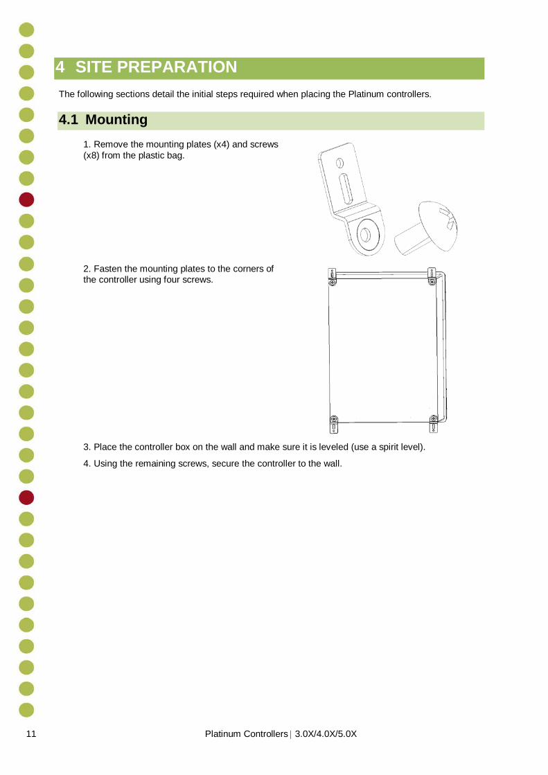
4.1 Mounting 1. Remove the mounting plates (x4) and screws (x8) from the plastic bag.
2. Fasten the mounting plates to the corners of the controller using four screws.
3. Place the controller box on the wall and make sure it is leveled (use a spirit level).
4. Using the remaining screws, secure the controller to the wall.

Platinum Controllers | 3.0X/4.0X/5.0X 12
4.2 Drilling Drill holes on the side and bottom of controller box according to the steps defined below. Use these holes to route the low and high voltage cables.
CAUTION Make sure not to damage cards when drilling holes. Locate holes properly before drilling!
1. Drill a hole on the right side of the controller box. Verify that the low voltage cables being used go through the hole properly.
Figure 3: Drilling on the Side 2. Drill a hole on the bottom side of the controller box. Verify that the high voltage cables being used fit through the hole properly.
NOTE: Rotem recommends drilling at least two (2) holes, 10 to 15 cm diameter each (dependent on the number of wires to be threaded). Place the holes as close to the front edge as possible (to avoid crowding the wiring).

13 Platinum Controllers | 3.0X/4.0X/5.0X
Figure 4: Drilling on the Bottom
3. Clean the holes from plastic shards. Verify that rims of holes are smooth.
Figure 5: Hole locations

Platinum Controllers | 3.0X/4.0X/5.0X 14
5 HIGH VOLTAGE WIRING This section details how to wire the controller’s high voltage wiring:
WARNING! Only a qualified electrician may perform the electrical installation!
ALERTE! Installer ce produit par un électricien agréé et formé comme spécifié dans votre code électrique national local.
● Power Supply, page 14 ● Relay Wiring, page 17 ● Winch Card Relay Wiring , page 19
WARNING! Before beginning, verify that the power supply has been disconnected!
ALERTE! Avant de démarrer, vérifiez que l’alimentation électrique ait été coupée !
5.1 Power Supply ● Main grounding wire should come connected to the ground terminal (1). ● Connect electricity to the controller power supply (2). ● Connect the grounding strip to the grounding rod (3). ● 230 VAC, 50/60 Hz; USA: L1, L2; ROW line, neutral (4)
Figure 6: Platinum Power Supply Wiring Diagram

15 Platinum Controllers | 3.0X/4.0X/5.0X
Figure 7: Platinum XL 50 Power Supply Wiring Diagram
5.1.1 RPLP Wiring The following section details how to wire an RPLP Lighting Protector unit to the power supply.
CAUTION Install the RPLP, 230 V only (part number P-RPLP-1-V2)!
On the RPLP's protected side: 1. Connect the RPLP grounding wire to the Platinum grounding terminal. 2. Connect the RPLP Neutral terminal to the Platinum L1 terminal. 3. Connect the RPLP Line terminal to the Platinum L2 terminal. ● 230 VAC, 50/60 Hz; USA: ground, L1, L2; ROW Ground, line, neutral (4) ● USA: L1, L2; ROW Line, Neutral (5)

Platinum Controllers | 3.0X/4.0X/5.0X 16
Figure 8: Wiring the Platinum RPLP
Figure 9: Wiring the Platinum XL 50 RPLP

17 Platinum Controllers | 3.0X/4.0X/5.0X
5.2 Relay Wiring This procedure details how to connect output relays to poultry house devices.
1. Connect the control phase commons to the relays’ contacts (the common wire to all relays with the same function).
Figure 10: Control Phase Commons
2. On the sticker below each relay, write the name of the device connected to the relay. 3. Connect the relay cables to each relay.
Figure 11: Relay Cable Connections
1 – 4: Exhaust fans 5: Tunnel fans 6: Control phase commons

Platinum Controllers | 3.0X/4.0X/5.0X 18
4. Connect the control phase cable to active multiple device on the same circuit breaker.
CAUTION A control phase wire is employed only outside of the USA.
Figure 12: Control Phase Cable Wiring
5. Locate the bag of stickers placed on the inside of the Platinum door. 6. On the front of the controller, place the appropriate label above the switch that corresponds with the electrical setup.
Figure 13: Controller labels
1: Control phase cable

19 Platinum Controllers | 3.0X/4.0X/5.0X
5.3 Winch Card Relay Wiring This procedure details how to connect Winch Cards to the inlets. Winch cards simplify backup (opening air sources such as inlets) in a power/heating event.
NOTE: Winch Cards are optional. Users employing an RBU-27 do not require Winch Cards. Rotem recommends that users employing an RBU-5 or RBU-3 install Winch Cards.
1. Connect separate control phase commons for each inlet or curtain.
NOTE: Winch cards are equipped with two Normally Closed relays.
Figure 14: Winch Card Control Phase Commons
2. Connect the control phase wire to phase commons.
Figure 15: Wiring Control Phase Wire to Phase Commons
3. Connect the output wires to the required device.
1: Open 2: Close 3: Connect control phase wire to L1
power port (inlet or tunnel machine)

Platinum Controllers | 3.0X/4.0X/5.0X 20
Figure 16: Connecting the Output Wire to Inlets/Curtains
1: Open 2: Close 3: To output devices

21 Platinum Controllers | 3.0X/4.0X/5.0X
5.4 Completing the Wiring ● Tie the cables together with tie wraps and route them as shown (through the high voltage
wiring holes drilled as shown in Drilling, page 12).
Figure 17: Wrapping the Cables in the Platinum Plus

Platinum Controllers | 3.0X/4.0X/5.0X 22
Figure 18: Wrapping the Cables in the Platinum XL 50

23 Platinum Controllers | 3.0X/4.0X/5.0X
6 EMERGENCY CARD INSTALLATION
The Emergency Card ensures operation of five Normally Closed outputs in the event of a main controller failure. The card features:
● An independent CPU ● An independent temperature sensor ● A battery and charger connection ● Battery status indicator
The five Normally Closed outputs are UL rated at 1.5 HP, 220 Volt. Rotem recommends that equipment rating not exceed:
● 1 HP 220 Volt ● ½ HP 110 Volt
Emergency cards are generally used for the following scenarios: ● To maintain minimum ventilation using fans during state of emergencies (meaning the
controller is not functioning). ● To operate the tunnel curtain open or side inlet.
NOTE: An Emergency Card is optional. If the battery falls below 12 volts, Platinum sends an alarm.
1. Loosen the four screws as shown and gently lift the metal plate.
Figure 19: Lifting the Metal Plate
2. Connect the Inside Temperature sensor to the Emergency Card.

Platinum Controllers | 3.0X/4.0X/5.0X 24
Figure 20: Wiring the Temperature Sensor to the EC
3. Connect the Emergency Card to the Emergency Battery Charger (PN: A-PP-EM-BAT). 4. Connect the Emergency Battery Charger to the supplied 12V battery. A: Black (-) B: Red (+)
5. Connect common wires and control phase wires onto Normally Closed cards for emergency situations.

25 Platinum Controllers | 3.0X/4.0X/5.0X
Figure 21: Common wires connected to Normally Closed cards
NOTE: For fans, connect separate phases from the circuit breakers.
6. Connect output wires to the ventilation device 7. Reattach the metal plate on the back door and tighten the four screws.

Platinum Controllers | 3.0X/4.0X/5.0X 26
7 SCALES INSTALLATION This section contains the following optional scale installations:
● Bird Scale, page 26 ● Feed Scale, page 28 ● Silo Scale, page 29
7.1 Bird Scale Wiring
Figure 22: Platinum Bird Scale Wiring
Key: 1: Neutral (L1 USA) 2: Phase (L2 USA) 3: Red 4: Green 5: Black 6: White

27 Platinum Controllers | 3.0X/4.0X/5.0X
Figure 23: Platinum XL 50 Bird Scale Wiring
Key: 1: Neutral (L1 USA) 2: Phase (L2 USA) 3: Red 4: Green 5: Black 6: White

Platinum Controllers | 3.0X/4.0X/5.0X 28
7.2 Feed Scale Wiring
NOTE: The feed software data plug is necessary only when the scale card is connected to a feed bin.
Figure 24: Feed Scale Wiring
NOTE: When using an RFC-1, swap between the red and white wiring. The feed scale’s red wire goes to the RLCC-4's white port and the feed scales white wire goes to the red port.
Key: 1: Ground
2: Neutral 3: Phase
4: Green 5: Red
6: White 7: Black
8: Software Plug

29 Platinum Controllers | 3.0X/4.0X/5.0X
7.3 Silo Scale Wiring ● Connect an external power supply and move the jumper to the EXT position.
o Bird scales: Bird scale power supply o Silo scales: Silo power supply o Bird and silo scales: Silo power supply
NOTE: A feed software data plug is needed only if the scale card is connected to a feed bin.
NOTE: Rotem recommends using the same power feed for the silo power supply and the controller; meaning that if you turn off the controller, the silo power also turns off.
Figure 25: Platinum Silo Scale Wiring
Key: 1: Silo Junction Box 2: Software plug 3: Silo power supply
Platinum Controllers | 3.0X/4.0X/5.0X 30
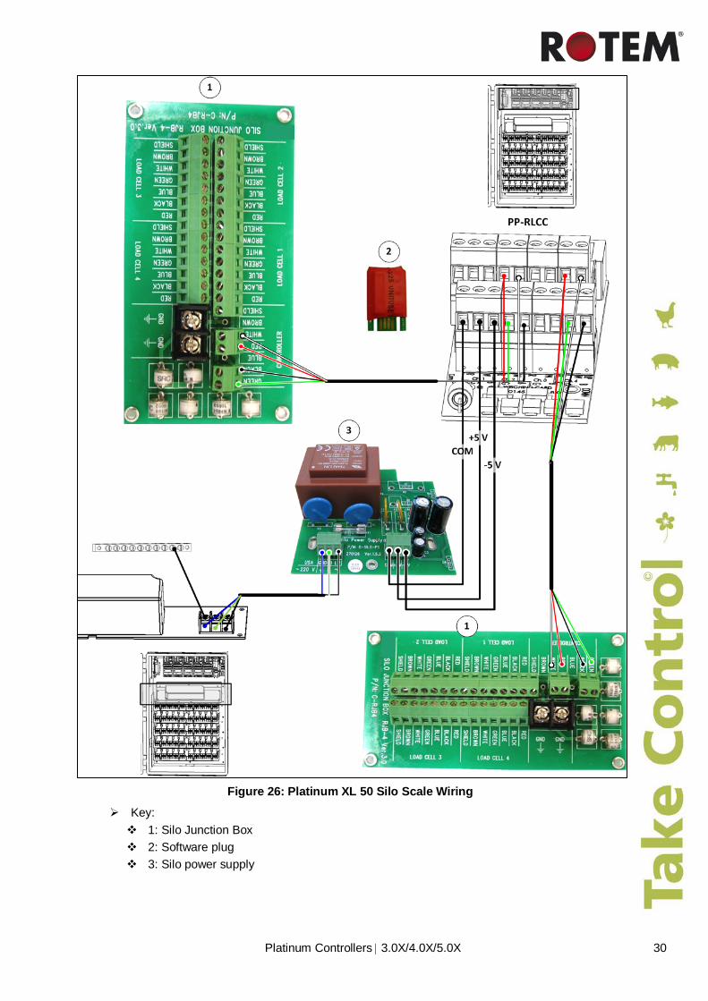
Figure 26: Platinum XL 50 Silo Scale Wiring
Key: 1: Silo Junction Box 2: Software plug 3: Silo power supply

31 Platinum Controllers | 3.0X/4.0X/5.0X
8 LOW VOLTAGE WIRING The following section details the:
● Analog Input Wiring, page 31 ● Weather Station Wiring, page 36 ● Platinum Plus Digital Input /Analog Output, page 37 ● Platinum Junior Digital Input /Analog Output page 41 ● Alarm Card Wiring, page 42 ● Communication Card Wiring, page 44
8.1 Analog Input Wiring The Platinum Controller can contain a maximum of two analog input cards (P/N: C-PP-RAIC-11). Each card consists of 11 inputs; a total of 22 analog inputs are available per controller. The analog input card enables defining each input’s function using jumpers.
The card supports the following options:
● Inputs 1 – 5 o Temperature sensors
See Analog Input Wiring Diagram for Temperature Sensors, page 32 ● Inputs 5 – 6
o Temperature sensors o CO2 sensor
See Analog Input Wiring Diagram for CO2 and Light Sensor, page 33
● Inputs 7 – 9 o Temperature sensors; o Or humidity sensors; o Or potentiometers
See Analog Input Wiring Diagram for Potentiometers, page 34 ● Input 10
o Humidity sensor See Analog Input Wiring Diagram for Humidity , page 35
● Input 11 o Wind direction sensor
See Analog Input Wiring Diagram for Humidity , page 35
The analog input cards include of surge and lightening protection circuits and do not require additional external protections.
CAUTION Use 22 AWG or lower, shielded cable only! Connect the shield to the safety ground in the Platinum Controller.
CAUTION Utilisez uniquement un câble blindé 22 AWG ou inférieur! Connectez la protection à la terre de manière sécurisée dans le contrôleur en platine.
CAUTION

Platinum Controllers | 3.0X/4.0X/5.0X 32
8.1.1 Analog Input Wiring Diagram for Temperature Sensors Connect the temperature sensor to an input, T1-T6, and to a COM.
● Terminals 1 - 4: These inputs are for temperature sensors only. ● Terminals 5 & 6: To use for temperature sensors place jumper on TEMP position as
illustrated.
NOTE: Every COM input is correct and more than one sensor can be connected to a COM input.
Figure 27: Temperature Sensor Wiring
1: Terminal 4 input 2: Terminal 5 input 3: Shield wire connected to ground strip

33 Platinum Controllers | 3.0X/4.0X/5.0X
8.1.2 Analog Input Wiring Diagram for CO2 and Light Sensor
NOTE: Version 3.03 and above support CO2 and Light sensors.
• Terminals 5 and 6: Connect the CO2 / light sensor to input T5 - T6 and to a COM. • To use for CO2 or light sensor, place the jumper on the 4 - 20 mA position as illustrated.
NOTE: Jumper must be on 4 - 20 mA position with corresponding terminal.
Figure 28: Light and CO2 Sensors Wiring
1: Terminal 6 input 2: Terminal 5 input 3: Red wiring (input terminal) 4: Shield wire connected to ground strip

Platinum Controllers | 3.0X/4.0X/5.0X 34
8.1.3 Analog Input Wiring Diagram for Potentiometers • Terminals 7, 8, and 9: To use as potentiometers remove jumpers from positions 7, 8 and 9.
NOTE: The potentiometer’s value should be 10 - 20 KOhm.
NOTE: No jumpers on the terminal are connected to the potentiometer.
Figure 29: Potentiometer Wiring
1: Terminal 7 input 2: Terminal 8 input 3: Terminal 9 input 4: Shield wire connected to ground strip

35 Platinum Controllers | 3.0X/4.0X/5.0X
8.1.4 Analog Input Wiring Diagram for Humidity Sensor ● Terminal 10: Humidity sensor: Connect according to the color code on the PCB.
Figure 30: Humidity Sensor Wiring
1: White wire 2: Red wire 3: Black wire 4: Green wire 5: Yellow wire
NOTE: Platinum Versions 3.06/4.06 support two humidity sensors. To enable a second sensor, on Terminals 7, 8, or 9 place jumper on the HUM position (Figure 30). In the Install > Analog Sensor menu, designate the slot as a humidity sensor.

Platinum Controllers | 3.0X/4.0X/5.0X 36
8.2 Weather Station Wiring ● Terminal 11: Wind Direction sensor: Connect according to the color code on the PCB
(setup in menu Service | Analog Sensors)
Figure 31: Weather Station Wiring
1: Green wire 2: Yellow wire 3: Black wire 4: Red wire 5: Wind direction sensor 6: Rain gauge
● The wind direction and speed (Yellow, Green) is connected to Input 11 only and is setup in Installation > Analog Sensors.
● Connect the Wind Sensor to any available input and set the input correspondently in the software Installation > Digital Sensors.
NOTE: If the Speed Sensor is not used. connect the red wire to the COM entry of the Analog Input Card.

37 Platinum Controllers | 3.0X/4.0X/5.0X
8.3 Platinum Plus Digital Input /Analog Output The following sections detail:
● Platinum Plus Digital Input Wiring, page 37 ● Platinum Plus Analog Output Wiring, page 38 ● Combo Card Wiring, page 39
NOTE: For information on the Platinum Junior wiring, refer to Platinum Junior Digital Input /Analog Output, page 39.
8.3.1 Platinum Plus Digital Input Wiring The Platinum Plus has a Digital Input Card (P/N: C-PP-RDIC8) with eight inputs which are used to measure digital sensors. Each input consists of a pair of ports:
● Left port: Common ● Right port: Signal input
It is possible to connect the common of several sensors to the same connector. However Rotem recommends spreading the commons in an even manner. The Digital Input Card includes surge and lightening protection circuits and does not require external protections.
Figure 32: C-PP-RDIC8 Wiring
1: Input 1 signal Examples of Digital Input Devices: 2: Input 2 signal • Auxiliary Alarm
3: Input 3 signal • Water Meter
4: Input 4 signal • Auger Overtime • Feed Counter

Platinum Controllers | 3.0X/4.0X/5.0X 38
8.3.2 Platinum Plus Analog Output Wiring The Platinum Plus has an Analog output card (C-PP-RAOC8) with eight outputs, which are used to drive external units controlled by 0 – 10 VDC. The analog outputs card consists of surge and lightening protection circuits and does not require external protections.
NOTE: Version 5.0X supports two analog output cards.
Figure 33: C-RAOC8 Wiring
1: Output 1: Light dimmer 2: Output 8: Variable speed fan 3: Shield wire to ground
Examples of Analog Output Devices: • Variable Speed Fans • Stir Fans • Light Dimmer
NOTE: The above drawing is only an example of many possible wiring diagrams. Your particular installation may differ.
NOTE: Users employing the Advanced Analog Input Card: refer to Appendix 1: Advanced Analog INPUT CARD, page 52.

39 Platinum Controllers | 3.0X/4.0X/5.0X
8.3.3 Combo Card Wiring
NOTE: This feature is only available in Version 3.02 or higher.
The Platinum features a Combo Card (P/N: PPJ-COMBO) which consists of:
● x8: Digital input card which serves as a general purpose digital input card for dry contact input such as water pulse, feed pulse, fertilizer pulse, etc.
● x4: Analog output card used to drive external units controlled by 0 – 10 VDC.
Figure 34: C-PPJ-COMBO Wiring
NOTE: The digital inputs and analog outputs shown in the figure above are examples only.
Key:
1: Variable fan 2: Light dimmer 3: Auger overtime
4: Feed counter 5: Water meter
8.4 Platinum Junior Digital Input /Analog Output The following sections detail the:
● Platinum Junior Digital Input Wiring, page 40 ● Platinum Junior Analog Output Assembly, page 41
NOTE: Users requiring eight digital inputs and four analog outputs can install a Combo Card (page 39).

Platinum Controllers | 3.0X/4.0X/5.0X 40
8.4.1 Platinum Junior Digital Input Wiring The Platinum Junior has a Digital Input Card (P/N: C- PPJ-DI8) with eight inputs which are used to measure digital sensors. The new card provides all the services of the Platinum Plus Digital Input Card (P/N: C-PP-RDIC8) while enabling a simple upgrade that adds four analog output ports (refer to the following section).
It is possible to connect the common of several sensors to the same connector. However Rotem recommends spreading the commons in an even manner. The Digital Input Card includes surge and lightening protection circuits and does not require external protections.
Figure 35: C-PPJ-COMBO Wiring
NOTE: The digital inputs and analog outputs shown in the figure above are examples only.
Key:
1: Variable fan 2: Light dimmer 3: Auger overtime
4: Feed counter 5: Water meter Examples of Digital Input Devices:
• Water Meter • Feed Counter • Auger Overtime ● Auxiliary Alarm

41 Platinum Controllers | 3.0X/4.0X/5.0X
8.4.2 Platinum Junior Analog Output Assembly By adding a Combo Analog Output Card (P/N: P-PPJ-AO4) to the Digital Input Card, you can add four analog outputs.
Figure 36: P-PPJ-AO4 Card
NOTE: Users requiring eight analog outputs should install an Analog Output Card (C-PP-RAOC8).
To assemble the card:
1. Place the Combo Analog Output Card on the Digital Input Combo Card as shown in the following illustration.
Figure 37: Card Assembly
1: Male/female ports 2. Gently press the Analog Output Card down until the connectors snap in place. 3. In the Platinum menu, go to Test > Hardware Checklist. 4. Verify that Analog Output is checked (Figure 38).

Platinum Controllers | 3.0X/4.0X/5.0X 42
Figure 38: Hardware Checklist
8.5 Alarm Card Wiring Rotem’s Alarm Card (C-PP-RALC-2) provides integrated lightning protection for a single alarm device of up to 430 Volts DC. If you need to protect more than one device, use Rotem’s P-RLVP to protect low voltage devices or the RPLP for line voltage devices.
NOTE: The Platinum Plus, Junior, XL, and XL-50 support this card. The Platinum Junior Controller does not support this card.
The following section details the:
• Normally Open Alarm System, page 42 • Normally Close Alarm System, page 43 ● Siren Wiring Diagram , page 43
8.5.1 Normally Open Alarm System Wiring Suggested Alarm System Connection: To provide lightning protection to the alarm, install the blue wires using the same terminals as the alarm device.
Alarm system
The alarm card provides NO (Normally Open) and NC (Normally Closed) connections on two independent terminals. Connect the protection wires to the terminal with the most critical device if you use more than one device.
HARDWARE CHECKLIST
Description Found Relays Analog Input √ Digital Input √ Analog Output √ Scales √ Static Pressure √ Alarm √ N.C. Emergency Card 1 5 N.O. Switch Card 7 35 N.C. Switch Card 0 0 Vent Board/Curtain Card 0 0

43 Platinum Controllers | 3.0X/4.0X/5.0X
8.5.2 Normally Close Alarm System Wiring In a NC wiring system, an alarm dialer is connected to the NC and COM terminals on the upper connector. The protection wires protect the dialer and the alarm card.
NOTE: The alarm relay is held so the NC connections are open and the NO connections are closed when there is NO alarm. This feature provides automatic power fail alarms if the system loses power to the alarm card.
1: 12V dialler
NOTE: The blue wires are lightning protection wires. Connect the blue wires to the terminal requiring protection together with the device, such as an alarm dialler.
8.5.3 Siren Wiring Diagram You can use the protection for other devices such as a simple siren. If you need to protect more than one device, use Rotem’s P-RLVP to protect low voltage devices or the RPLP for line voltage devices.
1: 12V battery

Platinum Controllers | 3.0X/4.0X/5.0X 44
8.6 Communication Card Wiring
NOTE: The communication option provides a means to connect a personal computer locally or remotely by modem.
Figure 39: Controller – MUX RS-232 Wiring
1: Communication card 2: Long distance 3: Connect the cable shields only at 1) one end
of every cable 2) one end of each house 4: Connect shield to
GND 5: Neutral See below 7: Modem (priority channel) 8: COM 1, 2 9 PC

45 Platinum Controllers | 3.0X/4.0X/5.0X
Figure 40: Controller – Communicator Isolated RS-485 Wiring
NOTE: When deploying an RS-485 infrastructure, Rotem strongly recommends using an Isolated RS-485 communication card.

Platinum Controllers | 3.0X/4.0X/5.0X 46
9 TROUBLESHOOTING
Display Problem Possible Cause Possible Solution
Many error messages appear on the display.
Platinum general problem
(Relays are not operating in auto mode and many error messages appear)
I/O BUS (I2C) is stuck
Disconnect the bridge card between the CPU card and the switch bus, and check if the LED on the alarm card is blinking.
If the LED on the alarm card is not blinking, it means that the problem is in one of the I/O cards.
In this case, the next step is to find which card is the faulty one.
Switch Bus (I2C) is stuck
Disconnect the bridge card between the CPU card and the switch bus, and check if the LED on the alarm card is blinking.
If the LED on the alarm card is blinking, it means that one of the switch cards (or the switch bus itself) caused the I2C bus problem.
In this case, the next step is to find which switch card is the faulty one.
LEDs in the switches and alarm cards are not blinking
One of the switch cards holds the I2C Bus
Faulty switch card
1. Return the jumper between the CPU and the switch bus. 2. To find which card holds the I2C BUS, disconnect an entire line (2 switch cards) by removing a bridge card. 3. See if the switch cards on the other lines start blinking:
● If they start blinking it means that you removed the faulty line (one of the cards is faulty).
● If not, return the bridge back and disconnect another line (repeat this procedure until you find the faulty line (one of the two switch cards is faulty).
4. Find out which of the two is faulty and replace it.

47 Platinum Controllers | 3.0X/4.0X/5.0X
Display Problem Possible Cause Possible Solution
LEDs in the switches and alarm cards are not blinking
One of the I/O cards holds the I2C Bus
Faulty I/ O card
(Analog Input, Analog Output, Digital Input, Load Cell Card)
1. Disconnect all of the input/output cards (Analog Input, Analog Output, Digital Input, Load Cell Card) one by one and check if the Alarm Card LED start blinking (or the sensors are read correctly). 2. If you can’t find the faulty card this way, use a known spare card to check if CPU recognizes it. If not, replace the CPU card. 3. Check that all the jumpers and flat cables between the cards are properly installed and plugged into the right place.
NOTE: Check that all the bridges and Flat cables between the cards are properly installed and plugged into the right place.
LED in the switch card is off
One of the switch cards and its related relay card are not working at all.
A short in one of the relays coil. Short activates a thermal fuse on the switch card.
Replace the relay card. If the problem persists replace the switch card as well.

Platinum Controllers | 3.0X/4.0X/5.0X 48
Display Problem Possible Cause Possible Solution
Fail message in the Sensors List in the Main Screen
Temperature sensor shorted
Short circuit in the related sensor entry
1. Measure the voltage of the right temperature sensor (according to the number from the sensor list) and check if the voltage is close to zero (normally it should be around 2.5 V). 2. If it shows zero volts, disconnect the sensor and connect an ohmmeter between the black and red wires of the sensor. Check if there is 30 KOhm (at 25° C). If the temperature is higher than 25° C the resistance should be lower than 30 KOhm, and vice versa. 3. If the resistance is too low, then replace the sensor (the resistance should be around 30 KOhm at 25° C or 15 KOhm at 40° C).
Temperature sensor opened
Open circuit in the related sensor entry
1. Check if the sensor is properly connected to the right terminal (according to the number from the sensor list). 2. Measure the voltage of the temperature sensor and check if the voltage is close to 5 V (normally around 2.5 V). 3. If it shows 5 V, disconnect the sensor and connect an ohmmeter between the black and red wires of the sensor. Check if there is 30 KOhm (at 25° C). If the temperature is higher than 25° C the resistance should be lower than 30 KOhm, and vice versa. 4. If the resistance too high than replace the sensor (resistance should be around 30 KOhm at 25° C or 100 KOhm at 0° C).
Temp Sensor User Err
Sensor defined in Temp Definition but not in Analog Sensor Installation
Define sensor correctly.
No readings from a digital input.
Faulty digital input card
1. Enter into the test state and you see a list of eight inputs. 2. Disconnect the wires from the input you want to check and see that it shows '0'. If it shows '1' then the input is faulty and the card should be replaced (or try to use some other input if there is a free one). 3. Check that when you create a short on the input, the '0' changes into '1'. If it doesn't then the input is faulty and the card should be replaced.
Analog Input Fail
Fail message in messages list on main screen
Missing or faulty analog input card
1. Check that the analog input card is connected properly. 2. If it is properly connected and the problem still exists, replace the analog input card.
Scale Card Fail
Fail message in messages list on main screen
Missing or faulty scale card
1. Check that the analog input card is connected properly. 2. If it is properly connected and the problem still exists, replace the analog input card.

49 Platinum Controllers | 3.0X/4.0X/5.0X
Display Problem Possible Cause Possible Solution
Clock Fail Clock failure
Malfunction of the clock circuit on the CPU card
Replace the CPU card.
Bird Scale 1 (or 2) Failure
The Platinum does not read correctly the bird scale input (1 or 2).
Faulty bird scale or bad connection to the Platinum
1. Check that the wires are connected properly to the scale card entry. 2. To isolate the problem change the connections between entry #1 and entry #2. If the message of the Platinum remains with the same number, it means that the entry of the scale card is faulty. If the number in the message changes, it means that the scale (or the cable) is faulty.
Scale card missing
Fail message during calibration procedure:
Disconnected Channel!!!
Undefined channel!!!
Fail message in messages list on main screen
Missing scale power supply
Faulty scale card
Wired incorrectly or disconnected wire
The reason for this problem may be either a card malfunction or scale power supply failure. Check the voltage between the green and black wires. The reading should be 10 V.
If the reading is not 10 V replace the external power supply. In the power supply there are also two status LEDs +5 V and -5 V that should be lit.
If the power supply functions properly:
1. Enter the test scale menu and check the A/D readings. The pulse should increase when pushing the plate. If the readings decrease switch between the red and white wires on the scale card. 2. Disconnect the load cell from the scale card and test resistance on points on the load cell.
• If the readings do not match the required values, replace the load cell in the platform.
• If in the Scale > Test menu the controller displays “N/A” for STATUS and the A/D count is 65,536, a higher reading, or 0, then a voltage measurement is required to identify the cause of the problem.
3. Check load cell receives voltage from the controller's green and black wires. The voltage should be approximately 10 DCV.
• If the load cell is not receiving voltage, check that the wires are connected properly on the controller side.
• If there is a 10 DCV, the load cells must be checked.
4. Take the Red and White wires from the load cell and check their voltage using a DVM on DCV range 200 mV or Auto range. The range of voltage should be between 0 to 20 mV, depending on bird scale load (more than 20 mV indicates a bad load cell). There are some cases when the prior test is not effective and the voltage between the Green and White wires and the Red and Green wires must be checked. (The amount of voltage must be between 4.4 - 5 V).

Platinum Controllers | 3.0X/4.0X/5.0X 50
Display Problem Possible Cause Possible Solution
Analog Output Missing Light Dimmer LED blinks at a certain percentage
Analog output card disappears (caused by noise interference) or Light Dimmer LED blinks at a certain %
Test the outputs voltage, insert a certain voltage, for example 5 V and check if the output produces 5 VDC (+ and – 5%). Make sure you are checking the same output that you programmed. Repeat the test with 10 VDC (+ and – 5%). Check all eight outputs the same way. If one of the outputs is producing a different voltage, replace the card.
Pressure Sensor Fail
Incorrect pressure measurements
1. Disconnect the plastic tubule from the platinum to verify zero pressure. 2. Enter the pressure calibration table and check the A/D counts on the top part of the screen. If they are not set to 130 use the blue trimmer on the pressure card to change them to 130. 3. If the trimmer does not change the A/D counts, replace the pressure card. 4. Software calibration can also be used to calibrate to zero pressure when in the range of 130 ± 40 A/D reading.
System Message 100 Reset
System Messages 101-105
Might occur as a result of electrical noise (lightning, motors, etc.)
System Message 762
A malfunction that is related to one of the relay cards
Faulty switch card
1. Check that the small jumper card (that is connected to the switch card) is properly connected. 2. Check that the chip on socket is properly connected. 3. Replace the faulty switch card (the Alarms history displays the exact failure card).
Faulty relay card
1. Check the flat cable (between the switch card and the relay card) that is properly connected. 2. Replace the faulty relay card (The Alarms history displays the exact failure card)
Alarm Card Fail Alarm card malfunction
Faulty alarm card
1. Check that the chip on socket is properly connected. 2. If it doesn't help, replace the alarm card.
System Message 767
Backup / Emergency card malfunction
Faulty backup/ emergency card
1. Check that the small jumper card (that is connected to the switch card) is properly connected. 2. Check that the chip on socket is properly connected. If it doesn't help replace the emergency card.
System Message 8574
CPU card malfunction
Faulty CPU card
Restart the (turn the power OFF and ON) Platinum and see if the problem still exists.
• If it doesn't help check that all the chips on socket are properly connected.
• If it helped, replace the CPU card.

51 Platinum Controllers | 3.0X/4.0X/5.0X
Display Problem Possible Cause Possible Solution
Digital Card Failure
Digital input card malfunction
Faulty digital input card
1. Check that the chip in the socket is properly connected. 2. If chip is in place and still malfunctioning, replace the digital input card.
System Message 107
Saving to the EEPROM malfunction
Faulty CPU card
Restart the (turn the power OFF and ON) Platinum and see if the problems still exists.
• If restart does not solve the problem, check that all the chips are in the sockets and connected properly.
• If the restart worked, replace the CPU card.
Vent Failure Vent reporting wrong position
Jumpers in relevant inputs are still there
Remove jumpers from relevant analog Inputs.
Potentiometer is not fixed to vent movement
Fix potentiometer to vent
Faulty potentiometer
Test analog input value. If needed, replace potentiometer (10-20 KOhm)
Wrong wiring Check and fix wiring

Platinum Controllers | 3.0X/4.0X/5.0X 52
10 APPENDIX 1: ADVANCED ANALOG INPUT CARD As an option, users can install Rotem's Advanced Analog Input Card (P/N: C-PP-RAIC11-SEL / P-PP-RAIC11-SEL) which enables greater flexibility in choosing input ports for analog devices or potentiometers. When using this analog input card, you can wire the device's signal input wire to any input port.
● Wire the device's signal input wire to any input port ● Place the jumper on the required position (see the following table)
Table 1: Jumper position
Device Jumper location Device Jumper location
CO2 Sensor 4 - 20 Humidity Sensor 0 – 5V
Light Sensor 4 - 20 Wind Direction Sensor WND
Temperature Sensor Temp Potentiometer None
● Analog Device ● Potentiometer
10.1 Analog Device To install an analog device: 1. Connect the device's COM signal to a COM port. 2. Connect the device's input signal to any input port.
Figure 41: Advanced Analog Input Card Wiring (Example)
1: Terminal 11 input 2: Terminal 7 input 3: Terminal 5 input
NOTE: Figure 41 is an example only. The input wires can go to any port.
NOTE: When installing a wind sensor, connect it to Input 11 only. Place the jumper on WND..

53 Platinum Controllers | 3.0X/4.0X/5.0X
3. Place that input port's jumper on the required position:
Figure 42: Jumper Placement (Example)
• 1: Terminal 11 input • 2: Terminal 7 input • 3: Terminal 5 input
10.2 Potentiometer To install a potentiometer: 1. Connect the device's COM signal to a COM port. 2. Connect the device's input signal to any input port. 3. Connect the 5V signal to an input port.
Figure 43: Potentiometer Wiring (Example)
4. Remove the jumper from the relevant input terminal.