Platform Machining Evaluation · Platform Machining Evaluation Air Methods 5a. ... UH-60M into the...
14
Platform Machining Evaluation Project Number #NP06009505 Contract Number #W31P4Q-05-D-R003 Final Report Revision 3 – September 21, 2006 Air Methods Englewood, Co. Submitted by Doug Perillo National Center for Defense Manufacturing & Machining Doug Perillo, Project Engineer 1600 Technology Way Latrobe, PA 15650 (724) 539-5901 Phone (724) 539-5132 fax www.ncdmm.org
Transcript of Platform Machining Evaluation · Platform Machining Evaluation Air Methods 5a. ... UH-60M into the...

Platform Machining Evaluation
Project Number #NP06009505Contract Number #W31P4Q-05-D-R003
Final ReportRevision 3 – September 21, 2006
Air MethodsEnglewood, Co.
Submitted by
Doug Perillo
National Center for Defense Manufacturing & MachiningDoug Perillo, Project Engineer
1600 Technology WayLatrobe, PA 15650
(724) 539-5901 Phone(724) 539-5132 fax
www.ncdmm.org
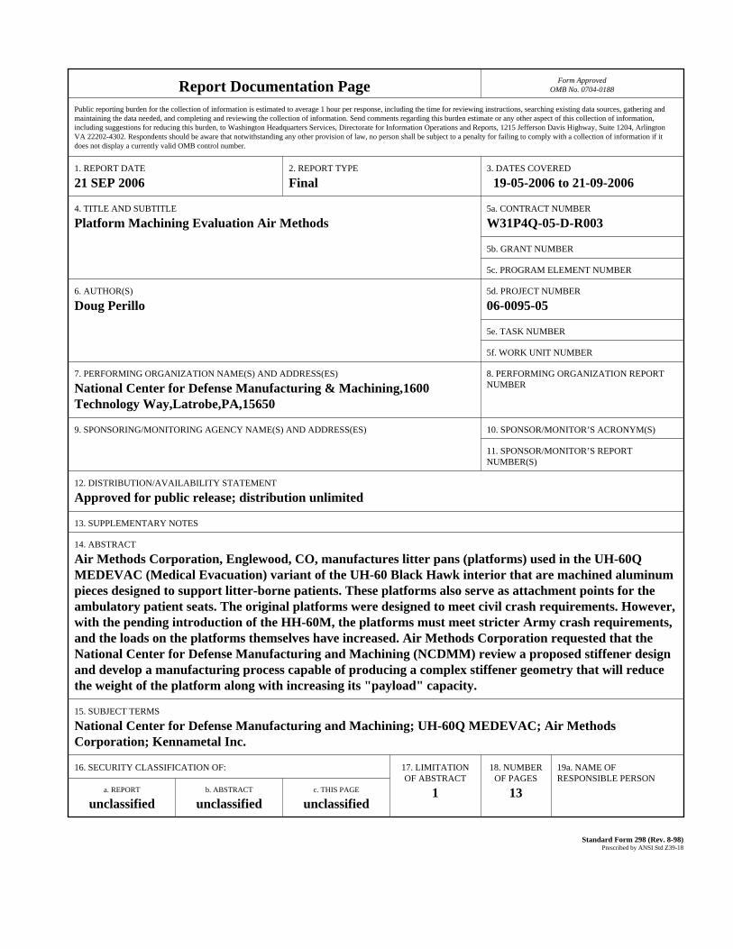
Report Documentation Page Form ApprovedOMB No. 0704-0188
Public reporting burden for the collection of information is estimated to average 1 hour per response, including the time for reviewing instructions, searching existing data sources, gathering andmaintaining the data needed, and completing and reviewing the collection of information. Send comments regarding this burden estimate or any other aspect of this collection of information,including suggestions for reducing this burden, to Washington Headquarters Services, Directorate for Information Operations and Reports, 1215 Jefferson Davis Highway, Suite 1204, ArlingtonVA 22202-4302. Respondents should be aware that notwithstanding any other provision of law, no person shall be subject to a penalty for failing to comply with a collection of information if itdoes not display a currently valid OMB control number.
1. REPORT DATE 21 SEP 2006
2. REPORT TYPE Final
3. DATES COVERED 19-05-2006 to 21-09-2006
4. TITLE AND SUBTITLE Platform Machining Evaluation Air Methods
5a. CONTRACT NUMBER W31P4Q-05-D-R003
5b. GRANT NUMBER
5c. PROGRAM ELEMENT NUMBER
6. AUTHOR(S) Doug Perillo
5d. PROJECT NUMBER 06-0095-05
5e. TASK NUMBER
5f. WORK UNIT NUMBER
7. PERFORMING ORGANIZATION NAME(S) AND ADDRESS(ES) National Center for Defense Manufacturing & Machining,1600Technology Way,Latrobe,PA,15650
8. PERFORMING ORGANIZATION REPORT NUMBER
9. SPONSORING/MONITORING AGENCY NAME(S) AND ADDRESS(ES) 10. SPONSOR/MONITOR’S ACRONYM(S)
11. SPONSOR/MONITOR’S REPORT NUMBER(S)
12. DISTRIBUTION/AVAILABILITY STATEMENT Approved for public release; distribution unlimited
13. SUPPLEMENTARY NOTES
14. ABSTRACT Air Methods Corporation, Englewood, CO, manufactures litter pans (platforms) used in the UH-60QMEDEVAC (Medical Evacuation) variant of the UH-60 Black Hawk interior that are machined aluminumpieces designed to support litter-borne patients. These platforms also serve as attachment points for theambulatory patient seats. The original platforms were designed to meet civil crash requirements. However,with the pending introduction of the HH-60M, the platforms must meet stricter Army crash requirements,and the loads on the platforms themselves have increased. Air Methods Corporation requested that theNational Center for Defense Manufacturing and Machining (NCDMM) review a proposed stiffener designand develop a manufacturing process capable of producing a complex stiffener geometry that will reducethe weight of the platform along with increasing its "payload" capacity.
15. SUBJECT TERMS National Center for Defense Manufacturing and Machining; UH-60Q MEDEVAC; Air MethodsCorporation; Kennametal Inc.
16. SECURITY CLASSIFICATION OF: 17. LIMITATIONOF ABSTRACT
1
18. NUMBEROF PAGES
13
19a. NAME OFRESPONSIBLE PERSON
a. REPORT unclassified
b. ABSTRACT unclassified
c. THIS PAGE unclassified
Standard Form 298 (Rev. 8-98) Prescribed by ANSI Std Z39-18

Project Number #NP06009505 Page 2 of 13Contract Number #W31P4Q-05-D-R003
Air MethodsPlatform machining Evaluation
Prepared by: Doug Perillo
Executive SummaryIn 1996, the US Army began fielding the UH-60Q MEDEVAC (Medical
Evacuation) variant of the UH-60 Black Hawk. The MEDEVAC variant
fielding has continued in low-rate production since the HH-60L variant, but
has remained unchanged since its initial design. With the introduction of the
UH-60M into the Army’s fleet, the MEDEVAC fleet must keep pace to meet
the requirements of Aviation Transformation. With the pending introduction
of the new HH-60M version, the Army is faced with the conflicting goals of
reducing system weight and unit cost while simultaneously meeting tougher
crash loading standards for the patient care systems.
The litter pans (platforms) used in the MEDEVAC interior are machined
aluminum pieces designed to support a litter-borne patient during a crash,
and to also serve as an attachment point for the ambulatory patient seats.
The original platforms were designed to meet civil crash requirements.
However, for the HH-60M, the platforms must meet stricter Army crash
requirements, and the loads on the platforms themselves have increased.
The contractor has proposed increasing the structural strength of the
platforms by increasing the web thickness on the underside, but this
improvement comes at a penalty of increased weight.
Reducing the weight of the Medical Interior increases the performance
margin on the aircraft. This translates into increased “payload” capacity,
better performance, better fuel efficiency, and longer aircraft life.

Project Number #NP06009505 Page 3 of 13Contract Number #W31P4Q-05-D-R003
Therefore, Air Methods has requested that the National Center for Defense
Manufacturing and Machining (NCDMM) review proposed stiffener designs
and develop a manufacturing process capable of producing a complex
stiffener geometry that will reduce the weight of the platform along with
increasing its “payload” capacity.
Project Details
Air Methods along with the NCDMM engineers reviewed several improved
strength stiffener designs. Air Methods decided on a design that would
increase the bottom face contact surface of the platform. It is believed that
this increased platform surface will satisfy the demand for the increased load
on the UH-60Q Platform. The new design allowed for a 50% increase on the
contact surface. The old design, consisting of a straight wall, will be
replaced with an under cut wall with both the bottom and the top of the wall
having radii to strengthen and blend to the wider surface, see Figure #1.
Figure #1, Improved Design

Project Number #NP06009505 Page 4 of 13Contract Number #W31P4Q-05-D-R003
Based on the size of the UH-60Q platform, a team decision was made to
perform a “Proof-of-Concept” on a scaled down, single section of the
platform. The section would be 7” wide x 12” long x 1.75” thick. The
machined area would include two pockets 1.690” deep. The wall and floor
thickness would be maintained at .060”, see Figure #2.
Figure #2, Part Representation
The NCDMM engineers modeled the part using Mastercam software, while
developing the tool paths. High Speed Machining (HSM) techniques were
used along with thin wall machining techniques. When using HSM
techniques, lighter depths of cut (DOC) and faster feeds and speeds are used.
HSM requires tool paths that maintain a constant chip load, see Figure #3.
Smaller tools are used with high surface feet per minute (SFM). The use of
smaller tools helps to reduce the residual stress (generated by the cutting
action) from entering the part causing a warp condition.

Project Number #NP06009505 Page 5 of 13Contract Number #W31P4Q-05-D-R003
Figure 3, HSM tool path.
Thin wall machining is a technique that is used on walls less than .100”
thick. When machining the part, larger roughing stock values are left all
around the part. On this particular part it was decided to leave .100” on all
surfaces. This extra stock will then be removed during the finish cut. The
tool used to thin wall machine is also modified with shank clearance. This
clearance is required so that the tool will not rub as it steps down the
finished wall, see Figure #4.
Figure #4, Visual of Thin Wall Machining

Project Number #NP06009505 Page 6 of 13Contract Number #W31P4Q-05-D-R003
The additional stock strengthens the wall at the cutting point, which reduces
the amount of push resulting from thin walls.
Using all of these techniques, the NCDMM technicians generated tool paths
to rough out the complete part leaving .100” of material on the walls for the
finish cut, see Figure #5.
Figure #5, Roughing Tool Path
The selected roughing tool was a .500” diameter, three (3) flute, 37-degree
helix end mill. This end mill is a standard Kennametal product and is
designed for cutting aluminum. Clearance was ground on the shank to avoid
rubbing during deep cutting, see Figure #6 and Figure #7.

Project Number #NP06009505 Page 7 of 13Contract Number #W31P4Q-05-D-R003
Figure #6, Kennametal HPF37A Figure #7, Shank Relief
The Kennametal HPF37A is a solid carbide end mill grade KC651M. The
coating on the end mill is a TiB2, which is an extreamly hard coating that
provides very good ware characteristic at high cutting speeds. It reduces
edge built up and can help reduce burring. The roughing cycle was
preformed at 1200 SFM, which equates to 9168 revolutions per minute
(RPM). The axial depth of cut (ADOC) chosen equaled .200” and the radial
width of cut (RWOC) chosen equaled 75% of the tool diameter. The feed
was preformed at .004 inches per tooth (IPT), which results in 110.0 inches
per minute (IPT)
The tool holder chosen for both roughing and finishing was a Kennametal
Powergrip milling chuck, see Figure #8.
Figure #8, Powergrip Milling Chuck

Project Number #NP06009505 Page 8 of 13Contract Number #W31P4Q-05-D-R003
The roughing cycle resulted in a 25minute run time. Each pocket along with
the out side periphery were roughed complete to the step depth of .200”
before moving to next step depth.
Finishing paths were developed in Mastercam software using a custom
ground, HPF37A end mill. The tool was ground with a shank relief and the
required .032” radius both on top and bottom, see Figure #9. This radius will
achieve the required geometry on the top as well as the bottom of the
recessed platform wall.
Figure #9, Custom Tool Geometry

Project Number #NP06009505 Page 9 of 13Contract Number #W31P4Q-05-D-R003
The first step in the finishing process was to machine the walls to size. This
was completed in .100” axial steps. The axial step depth is determined by the
grind on the form tool. It should be noted that this could have been greater,
which would result in less run time by reducing the number of passes. The
finish cycle was preformed at 1000 SFM, which equates to 7640 RPM. The
feed was preformed at .0025” IPT or 57” IPM. The tool path was similar to
the roughing where each pocket and the outside periphery were machined
complete to a predetermined step depth before moving to next step depth,
see Figure #10.
Figure #10, Finish Tool Path
The .100” axial step was repeated to the depth of 1.590”, allowing for the
.100” stock on the floor.

Project Number #NP06009505 Page 10 of 13Contract Number #W31P4Q-05-D-R003
The next step in the finishing process required machining the .100” stock
from the floor. Using another thin wall technique, this was completed in
each pocket resulting in the required .060” floor thickness. The technique
requires machining from the center of the pocket outward towards the pocket
walls. This method assures that all the machining is taking place at the
strongest area on the floor; see Figure #11 and Figure #12.
Figure #11, Example of Thin Floor Machining
Figure #12, Tool Path for Floor Finish
Project Number #NP06009505 Page 11 of 13Contract Number #W31P4Q-05-D-R003
The floor was then finished to a depth of 1.690”. The floor path blended the
floor to the walls with the required .032” radius.
Conclusion
Using state-of-the-market technology and methods described above, the
scaled down version of the platform was machined resulting in a total run
time of 55 minutes. The NCDMM feels that continuing the testing and tool
path refinement, the total run can be further reduced. It is believed that this
increased platform surface will satisfy the Army’s demand for the increased
“payload” on the UH-60Q MEDEVAC Platform. This new design could
potentially reduce the weight of the platform by 30%, in some areas, and
also allow for a 50% increase on the contact surface over the old, straight
wall design. The “Proof-of-Concept” produced by the NCDMM, from this
new design, met all the required geometric part tolerances; see Figure #13
thru Figure #15.
The NCDMM also recommends that several improved platform styles be
compared through Finite Element Analysis (FEA). The NCDMM would be
able to review any platform styles developed by Air Methods and also
provide assistance in that development. The NCDMM would also be able to
provide recommendations on any machinability issues that may arise during
the machining of the new platform styles.

Project Number #NP06009505 Page 12 of 13Contract Number #W31P4Q-05-D-R003
Figure #13, Finished Part
Figure #14, Part Corner & Recessed Wall

Project Number #NP06009505 Page 13 of 13Contract Number #W31P4Q-05-D-R003
Figure #15, Outside Periphery of Part
This technical report made possible by theUnited States Army
Army Material Command (AMC)Research, Development and Engineering Command (RDECOM)
Aviation and Missile Research, Development and Engineering Center (AMRDEC)Engineering Directorate (ED)
Manufacturing Science and Technology Division (MST)Redstone Arsenal, Alabama
Scott A. Hofacker, PE – Program Manager [email protected]
or Mike Cummings (Tiburon) [email protected]