Platform: DBALL/DBALL2 Firmware: FORD4 Rev.: 20150106
16
Index Installation Guide Update Alert: Firmware updates are posted to the web on a regular basis. We recommend that you check for firmware and/or install guide updates prior to installing this product. © 2015 Directed. All rights reserved. Rev.: 20150106 Platform: DBALL/DBALL2 Firmware: FORD4 Data override and door lock interface compatible with specific Ford vehicles equipped with SA type keys. Some of the available features include: transponder override, door lock control, factory security control, trunk release, tach sensing, as well as door, hood and trunk sensing. Two (2) master keys required for programming when doing a regular installation. One (1) master key required if using Key2GO feature, see page 2 for more information. ® Ford is a registered trademark and property of its respective company. Vehicle Application Guide................................................................................................................................................ Key2GO........................................................................................................................................................................... Installation Type 1.............................................................................................................................................................................. Type 1 with T-Harness THFD1........................................................................................................................................ Type 2.............................................................................................................................................................................. Type 2 with T-Harness THFD1........................................................................................................................................ Type 3.............................................................................................................................................................................. Type 3 with T-Harness THFD1........................................................................................................................................ Vehicle Wiring Reference Charts..................................................................................................................................... Programming Module Programming ..................................................................................................................................................... Module Reset and Hard Reset........................................................................................................................................ Feature and Option List................................................................................................................................................... Feature Programming...................................................................................................................................................... LED Diagnostics and Troubleshooting............................................................................................................................ Limited One-Year Consumer Warranty ............................................................................................................................ Quick Reference Guide................................................................................................................................................... 02 02 03 04 05 06 07 08 09 10 12 13 13 14 15 16
Transcript of Platform: DBALL/DBALL2 Firmware: FORD4 Rev.: 20150106

Index
Installation Guide
Update Alert: Firmware updates are posted to the web on a regular basis. We recommend that you check for firmware and/or install guide updates prior to installing this product.
© 2015 Directed. All rights reserved.
Rev.: 20150106
Platform: DBALL/DBALL2Firmware: FORD4
Data override and door lock interface compatible with specific Ford vehicles equipped with SA type keys. Some of the available features include: transponder override, door lock control, factory security control, trunk release, tach sensing, as well as door, hood and trunk sensing.
Two (2) master keys required for programming when doing a regular installation. One (1) master key required if using Key2GO feature, see page 2 for more information.
® Ford is a registered trademark and property of its respective company.
Vehicle Application Guide................................................................................................................................................
Key2GO...........................................................................................................................................................................
InstallationType 1..............................................................................................................................................................................Type 1 with T-Harness THFD1........................................................................................................................................Type 2..............................................................................................................................................................................Type 2 with T-Harness THFD1........................................................................................................................................Type 3..............................................................................................................................................................................Type 3 with T-Harness THFD1........................................................................................................................................Vehicle Wiring Reference Charts.....................................................................................................................................
ProgrammingModule Programming .....................................................................................................................................................Module Reset and Hard Reset........................................................................................................................................Feature and Option List...................................................................................................................................................Feature Programming......................................................................................................................................................
LED Diagnostics and Troubleshooting............................................................................................................................
Limited One-Year Consumer Warranty............................................................................................................................
Quick Reference Guide...................................................................................................................................................
02
02
03040506070809
10121313
14
15
16

© 2015 Directed. All rights reserved.
Rev.: 20150106
Platform: DBALL/DBALL2Firmware: FORD4
Page 2
Vehicle Application Guide
The following table lists the vehicles and features which are compatible with this product. The number assigned to each year allows you to determine which installation type should be used for your vehicle.
Vehicles
2015
2014
2013
2012
PK
-Im
mobilizer
Bypass-D
ata
No
Key
Req'd
DL-A
rmF
acto
ryS
ecurity
DL-D
isarm
Facto
ryS
ecurity
DL-D
oor
Lock
Contr
ol
DL-D
oor
Unlo
ck
DL-T
runk
/H
atc
hR
ele
ase
FO
B-C
ontr
olo
fafterm
ark
et
ala
rmw
ithO
EM
rem
ote
Key2G
O
RS
-RA
PS
hutD
ow
n
(Reta
ined
AC
CP
ow
er)
RS
-Tach
/R
PM
Outp
ut
SS
-Entr
yM
onito
ring
ALL
Door
Pin
s
SS
-Entr
yM
onito
ring
Driver
Door
Pin
SS
-Entr
yM
onito
ring
Hood
Pin
SS
-Entr
yM
onito
ring
Tru
nk/H
atc
hP
in
ST
-Bra
ke
Sta
tus
(footbra
ke)
ST
-Door
Locks
Sta
tus
ST
-E-B
rake
Sta
tus
Ford
C-Max 1 1 • • • • • D • • • • D • • D D D
Escape 1 1 1 • • • • • D • • • • D • • D D D
Focus 2 2 2 • • • • • • D • • • • D • • D D D
Transit Connect 3 • • • • • • D • • • • D • • D D D
Legend:
D: Data-to-Data (D2D) only DL: OE Door Lock & Alarm Controls RS: Remote Start & Status
•: D2D and Wire-to-Wire (W2W) FOB: Sync CAN Interface w/FOB Remote SS: Entry Point Status-Security
PK: Transponder & Immobilizer Override ST: Function/Feature Status
This feature is required if only one key is available. You can program the interface without the need for Key2Go if two keys are present.
Key2GO has been designed and developed to bypass the advanced encryption layers found in modern vehicles. It uses an array of servers to generate a duplicate of the original key, allowing the installation of a remote starter without having to give up a key.
The advantage is that this feature allows you to use one original key and the server to configure the bypass in the vehicle.
All Key2GO-compatible firmware are clearly indicated in the function list of each vehicle search result page and will also appear on the flash page. Any first-time user must re-register to gain access to Key2GO, and some additional information will be required to complete the registration process, such as your Directed account number and store name.
Key2GO is compatible with XpressVIP 4.5 or higher and requires an XKLoader.
Refer to page 11 of this guide for instructions on how to program features using Key2GO.

© 2015 Directed. All rights reserved.
Rev.: 20150106
Platform: DBALL/DBALL2Firmware: FORD4
Installation Type 1Page 3
Wires are listed by pin numbers. This display is not representative of connector pin layouts, which are often stacked.With the exception of the OBDII Diagnostic connector, all adapters are displayed from the wire side.
1
11
10
20
2
12
3
13
4
14
5
15
6
16
7
17
8
18
9
19
Rem
ote
Sta
rter
(-) Door/Trunk Status Output: Green/White: 3
[1] (-) Unlock 1 Output: Red/Black: 4
[2] (AC) Tach Output: Violet/White: 5
(-) Door Status Input
(+) Starter
[2] (AC) Tach Input
(-) Hood Input
(-) Hood Status Output: Blue/Red: 12
(-) Ground: Black: 14(-) Ground
(+) 12V: Red: 13(+) 12V
(+) Parking Lights
(+) Starter: Blue/White, pin 1
(+) Ignition
(-) GWR (Status)
(+) Start
(-) Lock Output
(-) Unlock Output
(-) Trunk Output
(-) Ground
10: Blue/White: (-) GWR (Status) Input
1: Green: (-) Lock Input
2: Blue: (-) Unlock Input
3: Red/White: (-) Trunk Input
9: Pink: (+) Ignition Input
8: Violet: (+) Start Input
RAP OFF: Orange/Red: 10
RAP OFF: Yellow/Red: 11
(+) Ignition Output: Yellow: 8
(+) 12V: Brown: 7 (+) 12V
(+) Accessory Output: Gray/Black: 7
Data TX: Yellow/Black: 10
Data RX: Orange/Black: 11
(-) Lock Output: Green/Black: 2
[1] (-) Unlock 2 Output: Black/White: 1
10
RF
Prog. Button
LED
4
14
12
2
P#: XKD2D65TX
(-) Ground
RX(+)12V
Junction Connector(near BCM)
2142
223
324
425
526
627
728
829
930
1031
1132
1233
1334
1435
1536
1637
1738
1839
1940
2041
122
22242
32343
42444
52545
62646
72747
82848
92949
103050
113151
123252
133353
143454
153555
163656
173757
183858
193959
204060
12141
(+) Parking Lights: Green/Orange or Yellow/Blue, pin 1(-) Unlock 2:
Blue/Brown,
pin 55
(-) Lock: Gray/Yellow, pin 36
MS CAN L: Violet/Orange, pin 40
(+) Parking Lights: Brown/Yellow, pin 26
MS CAN H: Gray/Orange,pin 41
C2280B (BCM)
C2280A (BCM)
6 ampdiodes
C2
28
0F
C2
28
0D
C2
28
0H
C2
28
0E
Bro
wn
C2
28
0B
Bro
wn
C2
28
0C
Blu
e
C2
28
0A
Gre
en
C2
28
0G
Gre
en
BCM (passenger side, behind glove box)
(+) 12V
(+) 12V: Red, pin 2
1
2
C2280G (BCM)
MS CAN High: Tan/Black: 3
MS CAN Low: Tan: 4
Driver Door Trigger: Green/Violet, pin 45
Not required in D2D mode.
[2] This wire is optional connection required on some remote starters, which do not support this signals in D2D.
[1] Both unlock wires need to be connected to wake up the system from sleep mode (ONLY on 2014 Escape & C-Max).
DBALL/DBALL2
2 22 42
3 23 43
4 24
5 25 45
6 26 46
7 27 47
8 28 48
9 29 49
10 30 50
11 31 51
12 32 52
13 33 53
14 34 54
15 35 55
16 36 56
17 37 57
18 38 58
19 39 59
20 40 60
1 21 41
C2280C (BCM)
(+) Accessory: Violet/Green,pin 44
Data RX: Violet/Gray,
pin 34
(-) Unlock 1: Violet/Gray orViolet/Orange,
pin 26 (+) Ignition: Brown/Yellow,pin 43
Data TX:Yellow/Orange,pin 54
44
The Unlock 2connection isONLYrequired on2014 Escapewithout one-touch windowcontrol.

© 2015 Directed. All rights reserved.
Rev.: 20150106
Platform: DBALL/DBALL2Firmware: FORD4
[2] This wire is optional connection required on some remote starters, which do not support this signals in D2D.
Page 4
With the exception of the OBDII Diagnostic connector, all adapters are displayed from the wire side (unless specified otherwise).
10
RF
Prog. Button
LED
4
14
12
2
Installation Type 1 with T-Harness (THFD1)
MSCAN H: Gray/Orange, pin 3
MSCAN L: Violet/Orange, pin 11
OBDII DiagnosticConnector
1 8
169
MSCAN High: Tan/Black
MSCAN Low: Tan
Connect to VehicleRefer to the Vehicle Wiring Reference chart on page 9
for more information.
The Unlock 2 connectionis ONLY required on 2014Escape without one-touchwindow control.
Driver Door Trigger
(-) Lock
(-) Unlock 1
(-) Unlock 2
[1] (-) Unlock 1 Output: Red/Black
[1] (-) Unlock 2 Output: Black/White
(-) Lock Output: Green/Black
RAP OFF: Yellow/Red
RAP OFF: Orange/Red
(+) Ignition Output: Pink
(+) Start: Purple
[2] (AC) Tach: Violet/White
Rem
ote
Sta
rter
(+) Start
[2] (AC) Tach
(-) Ground2142
223
324
425
526
627
728
829
930
1031
1132
1233
1334
1435
1536
1637
1738
1839
1940
2041
122
C2280A (BCM)
6 ampdiodes
(+) Parking Lights Output
(+) Ignition 1
(+) 12V
1
2
C2280G (BCM)
Violet
Attention! Cut loop in N O N - R S R
[1] Both unlock wires need to be connected to wake up the system from sleep mode (ONLY on 2014 Escape & C-Max).
DBALL/DBALL2
Do notconnect
P#: XKD2D65
TX
(-) Ground
RX(+)12V
Remote Start SafetyOverride Switch is inactive
(used for RSR only)
THFD1 Rev.2(Optional T-Harness)
Refer to the Vehicle Wiring Reference Chart on page 8 for more information on specific wiring and connections.
4321
4
1
3
2
Ignition Barrel
P.A.T.S.(black 4-pin connector)
(vehicle side)(vehicle side)
Ignition Switch(black 7-pin connector)
7421 3 5 6 1 432
2
2
2
2
5
5
5
5
3
3
3
3
6
6
6
6
4
4
4
4
1
1
1
1
7
7
7
7
(+) Parking Lights: Green/Orange or Yellow/Blue, pin 1
(+) Parking Lights: Brown/Yellow, pin 26
(+) 12V: Red, pin 2
D2Donly

© 2015 Directed. All rights reserved.
Rev.: 20150106
Platform: DBALL/DBALL2Firmware: FORD4
Installation Type 2Page 5
Wires are listed by pin numbers. This display is not representative of connector pin layouts, which are often stacked.With the exception of the OBDII Diagnostic connector, all adapters are displayed from the wire side.
21
11 1
25
24
23
13 3
20 10
17 716 6
19 9
15 5
18 8
14 4
27
22
12 2
26
Rem
ote
Sta
rter
(-) Door/Trunk Status Output: Green/White: 3
[1] (AC) Tach Output: Violet/White: 5
(-) Hood Status Output: Blue/Red: 12
(-) Ground: Black: 14(-) Ground
(+) 12V: Red: 13(+) 12V
(-) GWR (Status)
(+) Start
(-) Lock Output
(-) Unlock Output
(-) Trunk Output
(-) Lock/Unlock Output: Black/White: 1
RAP OFF: Orange/Red: 10
RAP OFF: Yellow/Red: 11
(+) Ignition Output: Yellow: 8
(+) Accessory Output: Gray/Black: 7
Data TX: Yellow/Black: 10
Data RX: Orange/Black: 11
10
RF
Prog. Button
LED
4
14
12
2
P#: XKD2D65TX
(-) Ground
RX(+)12V
JunctionConnector(near BCM)
(+) Parking Lights(+) 12V
1
2
C2280G (BCM)
(-) Trunk Activation Output: Violet/Brown: 9
(-) Door/Trunk Status Input
[1] (AC) Tach Input
(-) Hood Input
(+) Ignition 1
10: Blue/White: (-) GWR (Status) Input
1: Green: (-) Lock Input
2: Blue: (-) Unlock Input
3: Red/White: (-) Trunk Input
9: Pink: (+) Ignition Input
8: Violet: (+) Start Input
(-) Ground
2142
223
324
425
526
627
728
829
930
1031
1132
1233
1334
1435
1536
1637
1738
1839
1940
2041
122
22242
32343
42444
52545
62646
72747
82848
92949
103050
113151
123252
133353
143454
153555
163656
173757
183858
193959
204060
12141
(+) Parking Lights:Yellow/Blue, pin 1
(-) Trunk: Brown,
pin 49
Driver Door Trigger: Green/Violet,
pin 45
(+) Parking Lights:Brown/Yellow, pin 26
C2280B (BCM)
C2280A (BCM)
6 ampdiodes
(+) Starter
MSCAN High: Tan/Black: 3
MSCAN Low: Tan: 4
(+) 12V: Brown: 7(+) 12V
Not required in D2D mode.
[1] This wire is optional connection required on some remote starters, which do not support this signals in D2D.
DBALL/DBALL2
2 22 42
3 23 43
4 24
5 25 45
6 26 46
7 27 47
8 28 48
9 29 49
10 30 50
11 31 51
12 32 52
13 33 53
14 34 54
15 35 55
16 36 56
17 37 57
18 38 58
19 39 59
20 40 60
1 21 41
C2280C (BCM)
44
C2280F
C2280D
C2280H
C2280E
Bro
wn
C2280B
Bro
wn
C2280C
Blu
e
C2280A
Gre
en
C2280G
Gre
en
BCM (passenger side, behind glove box)
(+) Starter: Blue/White, pin 4
(+) 12V: Red, pin 2
MSCAN L: Violet/Orange, pin 40
MSCAN H: Gray/Orange,pin 41
(+) Accessory: Violet/Green,pin 44
Data RX: Violet/Gray,
pin 34
(-)Lock/ Unlock: Brown,
pin 11
(+) Ignition: Brown/Yellow,pin 43
Data TX:Yellow/Orange,pin 54

© 2015 Directed. All rights reserved.
Rev.: 20150106
Platform: DBALL/DBALL2Firmware: FORD4
[1] This wire is optional connection required on some remote starters, which do not support this signals in D2D.
Page 6
With the exception of the OBDII Diagnostic connector, all adapters are displayed from the wire side (unless specified otherwise).
Refer to the Vehicle Wiring Reference Chart on page 8 for more information on specific wiring and connections.
Installation Type 2 with T-Harness (THFD1)10
RF
Prog. Button
LED
4
14
12
2
OBDII DiagnosticConnector
1 8
169
MSCAN High: Tan/Black
MSCAN Low: Tan
THFD1 Rev.2(Optional T-Harness)
Driver Door Trigger
(-) Lock/Unlock
(-) Trunk (-) Trunk Activation Output: Violet/Brown
(-) Lock/Unlock Output: Black/White
RAP OFF: Yellow/Red
RAP OFF: Orange/Red
(+) Ignition Output: Pink
(+) Start: Purple
[1] (AC) Tach: Violet/White
Rem
ote
Sta
rter
(+) Start
[1] (AC) Tach
(-) Ground2142
223
324
425
526
627
728
829
930
1031
1132
1233
1334
1435
1536
1637
1738
1839
1940
2041
122
C2280A (BCM)
6 ampdiodes
(+) Parking Lights Output
(+) Ignition 1
(+) 12V
1
2
C2280G (BCM)
Violet
Attention! Cut loop in N O N - R S R
DBALL/DBALL2
Do notconnect
P#: XKD2D65
TX
(-) Ground
RX(+)12V
Remote Start SafetyOverride Switch is inactive
(used for RSR only)
Connect to VehicleRefer to the Vehicle Wiring Reference chart on page 9
for more information.
4321
4
1
3
2
Ignition Barrel
P.A.T.S.(black 4-pin connector)
(vehicle side)(vehicle side)
Ignition Switch(black 7-pin connector)
7421 3 5 6 1 432
2
2
2
2
5
5
5
5
3
3
3
3
6
6
6
6
4
4
4
4
1
1
1
1
7
7
7
7
MSCAN H: Gray/Orange, pin 3
MSCAN L: Violet/Orange, pin 11
(+) Parking Lights: Green/Orange or Yellow/Blue, pin 1
(+) Parking Lights: Brown/Yellow, pin 26
(+) 12V: Red, pin 2
D2Donly

© 2015 Directed. All rights reserved.
Rev.: 20150106
Platform: DBALL/DBALL2Firmware: FORD4
Installation Type 3Page 7
Wires are listed by pin numbers. This display is not representative of connector pin layouts, which are often stacked.With the exception of the OBDII Diagnostic connector, all adapters are displayed from the wire side.
21
11 1
25
24
23
13 3
20 10
17 716 6
19 9
15 5
18 8
14 4
27
22
12 2
26
Rem
ote
Sta
rter
(-) Door/Trunk Status Output: Green/White: 3
[1] (AC) Tach Output: Violet/White: 5
(-) Hood Status Output: Blue/Red: 12
(-) Ground: Black: 14(-) Ground
(+) 12V: Red: 13(+) 12V
(-) GWR (Status)
(+) Start
(-) Lock Output
(-) Unlock Output
(-) Trunk Output
(-) Unlock Output: Black/White: 1
RAP OFF: Orange/Red: 10
RAP OFF: Yellow/Red: 11
(+) Ignition Output: Yellow: 8
(+) Accessory Output: Gray/Black: 7
Data TX: Yellow/Black: 10Data RX: Orange/Black: 11
10
RF
Prog. Button
LED
4
14
12
2
P#: XKD2D65TX
(-) Ground
RX(+)12V
JunctionConnector(near BCM)
(+) Parking Lights(+) 12V
1
2
C2280G (BCM)
(-) Trunk Activation Output: Violet/Brown: 9
(-) Door/Trunk Status Input
[1] (AC) Tach Input
(-) Hood Input
(+) Ignition 1
10: Blue/White: (-) GWR (Status) Input
1: Green: (-) Lock Input
2: Blue: (-) Unlock Input
3: Red/White: (-) Trunk Input
9: Pink: (+) Ignition Input
8: Violet: (+) Start Input
(-) Ground
2142
223
324
425
526
627
728
829
930
1031
1132
1233
1334
1435
1536
1637
1738
1839
1940
2041
122
22242
32343
42444
52545
62646
72747
82848
92949
103050
113151
123252
133353
143454
153555
163656
173757
183858
193959
204060
12141
(+) Parking Lights:Yellow/Blue, pin 1
(-) Trunk: Brown,
pin 49
Driver Door Trigger: Green/Violet,
pin 45
(+) Parking Lights:Brown/Yellow, pin 26
C2280B (BCM)
C2280A (BCM)
6 ampdiodes
(+) Starter
MSCAN High: Tan/Black: 3
MSCAN Low: Tan: 4
(+) 12V: Brown: 7(+) 12V
Not required in D2D mode.
[1] This wire is optional connection required on some remote starters, which do not support this signals in D2D.
DBALL/DBALL2
2 22 42
3 23 43
4 24
5 25 45
6 26 46
7 27 47
8 28 48
9 29 49
10 30 50
11 31 51
12 32 52
13 33 53
14 34 54
15 35 55
16 36 56
17 37 57
18 38 58
19 39 59
20 40 60
1 21 41
C2280C (BCM)
44
C2280F
C2280D
C2280H
C2280E
Bro
wn
C2280B
Bro
wn
C2280C
Blu
e
C2280A
Gre
en
C2280G
Gre
en
BCM (passenger side, behind glove box)
(+) Starter: Blue/White, pin 4
(+) 12V: Red, pin 2
MSCAN L: Violet/Orange, pin 40
MSCAN H: Gray/Orange,pin 41
(+) Accessory: Violet/Green,pin 44
Data RX: Violet/Gray,
pin 34
(-) Unlock: Brown,
pin 26(+) Ignition: Brown/Yellow,pin 43
Data TX:Yellow/Orange,pin 54
(-) Lock Output: Green/Black: 2
(-) Lock: Gray/
Yellow, pin 36

© 2015 Directed. All rights reserved.
Rev.: 20150106
Platform: DBALL/DBALL2Firmware: FORD4
[1] This wire is optional connection required on some remote starters, which do not support this signals in D2D.
Page 8
With the exception of the OBDII Diagnostic connector, all adapters are displayed from the wire side (unless specified otherwise).
Refer to the Vehicle Wiring Reference Chart on page 8 for more information on specific wiring and connections.
Installation Type 3 with T-Harness (THFD1)10
RF
Prog. Button
LED
4
14
12
2
OBDII DiagnosticConnector
1 8
169
MSCAN High: Tan/Black
MSCAN Low: Tan
THFD1 Rev.2(Optional T-Harness)
Driver Door Trigger
(-) Lock/Unlock
(-) Trunk (-) Trunk Activation Output: Violet/Brown
(-) Lock/Unlock Output: Black/White
RAP OFF: Yellow/Red
RAP OFF: Orange/Red
(+) Ignition Output: Pink
(+) Start: Purple
[1] (AC) Tach: Violet/White
Rem
ote
Sta
rter
(+) Start
[1] (AC) Tach
(-) Ground2142
223
324
425
526
627
728
829
930
1031
1132
1233
1334
1435
1536
1637
1738
1839
1940
2041
122
C2280A (BCM)
6 ampdiodes
(+) Parking Lights Output
(+) Ignition 1
(+) 12V
1
2
C2280G (BCM)
Violet
Attention! Cut loop in N O N - R S R
DBALL/DBALL2
Do notconnect
P#: XKD2D65
TX
(-) Ground
RX(+)12V
Remote Start SafetyOverride Switch is inactive
(used for RSR only)
Connect to VehicleRefer to the Vehicle Wiring Reference chart on page 9
for more information.
4321
4
1
3
2
Ignition Barrel
P.A.T.S.(black 4-pin connector)
(vehicle side)(vehicle side)
Ignition Switch(black 7-pin connector)
7421 3 5 6 1 432
2
2
2
2
5
5
5
5
3
3
3
3
6
6
6
6
4
4
4
4
1
1
1
1
7
7
7
7
MSCAN H: Gray/Orange, pin 3
MSCAN L: Violet/Orange, pin 11
(+) Parking Lights: Green/Orange or Yellow/Blue, pin 1
(+) Parking Lights: Brown/Yellow, pin 26
(+) 12V: Red, pin 2
D2Donly
© 2015 Directed. All rights reserved.
Rev.: 20150106
Platform: DBALL/DBALL2Firmware: FORD4
Page 9
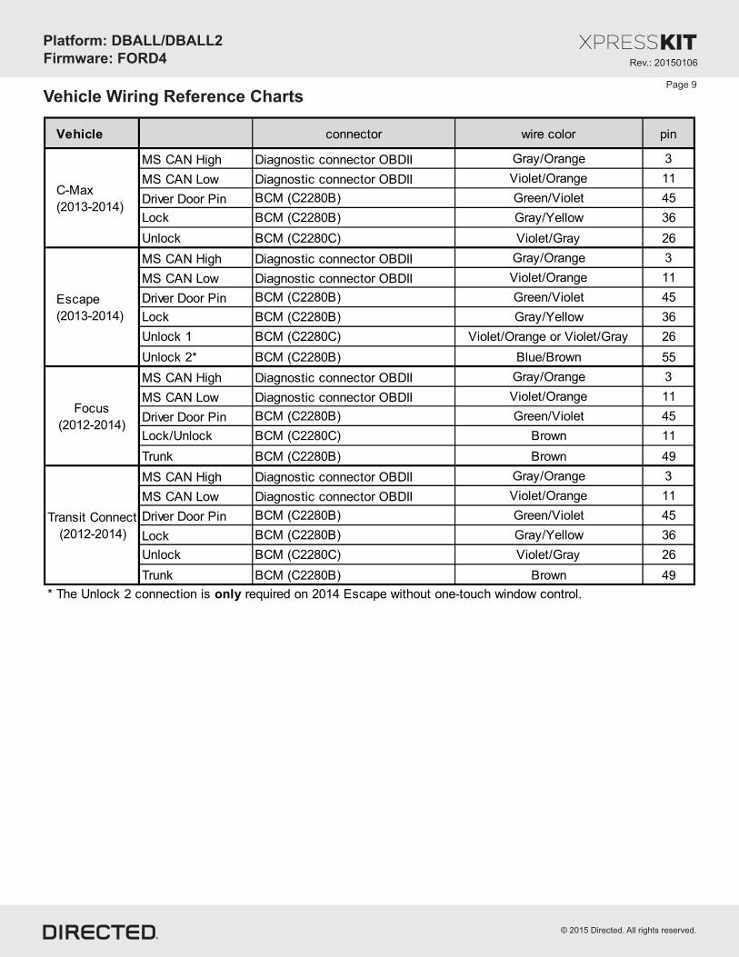
Vehicle Wiring Reference Charts
Vehicle connector wire color pin
MS CAN High Diagnostic connector OBDII Gray/Orange 3
MS CAN Low Diagnostic connector OBDII Violet/Orange 11
Driver Door Pin BCM (C2280B) Green/Violet 45
Lock BCM (C2280B) Gray/Yellow 36
Unlock BCM (C2280C) Violet/Gray 26
MS CAN High Diagnostic connector OBDII Gray/Orange 3
MS CAN Low Diagnostic connector OBDII Violet/Orange 11
Driver Door Pin BCM (C2280B) Green/Violet 45
Lock BCM (C2280B) Gray/Yellow 36
Unlock 1 BCM (C2280C) Violet/Orange or Violet/Gray 26
Unlock 2* BCM (C2280B) Blue/Brown 55
MS CAN High Diagnostic connector OBDII Gray/Orange 3
MS CAN Low Diagnostic connector OBDII Violet/Orange 11
Driver Door Pin BCM (C2280B) Green/Violet 45
Lock/Unlock BCM (C2280C) Brown 11
Trunk BCM (C2280B) Brown 49
MS CAN High Diagnostic connector OBDII Gray/Orange 3
MS CAN Low Diagnostic connector OBDII Violet/Orange 11
Driver Door Pin BCM (C2280B) Green/Violet 45
Lock BCM (C2280B) Gray/Yellow 36
Unlock BCM (C2280C) Violet/Gray 26
Trunk BCM (C2280B) Brown 49
* The Unlock 2 connection is only required on 2014 Escape without one-touch window control.
Escape
(2013-2014)
C-Max
(2013-2014)
Focus
(2012-2014)
Transit Connect
(2012-2014)

© 2015 Directed. All rights reserved.
Rev.: 20150106
Platform: DBALL/DBALL2Firmware: FORD4
Page 10
Refer to the LED Diagnostics section on page 14 more information and for troubleshooting purposes.
Module Programming
ImportantMake all the required connections to the vehicle, as described in the wiring diagram(s) found in this guide, and double check to ensure everything is correct prior to moving onto the next step.
Warning! To take advantage of advanced features, you must use XpressVIP 4.5 or higher. Using version 2.9 or 3.1 will limit available functions and features.
1. Connect the interface module to your computer using the XKLoader.
2. Open an Internet Explorer browser (version 6 or higher), and go to www.directechs.com. The detail of the platform and firmware that is currently saved on the interface module will be indicated in the top left corner of the page.
3. Select the year, make and model of the vehicle; the page will refresh to display the compatible firmware.
4. In the search result page, select Flash Standard install, and follow the instructions provided on the screen.5. Once you have configured your options, click on the FLASH button to upload the firmware onto the interface module.6. The following message will be displayed when the upload is completed:
“The flashing is successfully completed. You may now unplug the kit.”You can now proceed with the programming instructions below.
OR
If required for your installation, connect the 10-pin, 12-pin and 14-pin harnesses to the module, then connect the 4-pin D2D harness.
D2D Installation
W2W Installation
If required for your installation, connect the 10-pin and 12-pin harnesses to the module, then connect the 14-pin harness to the module.
10-pinD2D
st1
12-pin14-pin
nd2
rd3
10-pinD2D
st1
th4
12-pin14-pin
nd2
rd3
3Key at IGN
2nd Key IN OF
F
START
IGNInsert the second key and turn it to the IGN position:
the LED flashes orange. Wait at least 3 seconds but no more than 10 seconds, then remove the key.
within 5 seconds:
2Key at IGN
1st Key IN OF
F
START
IGNInsert the first key, turn the key to the IGN position,
the LED flashes green. Wait at least 3 seconds, but no more than 10 seconds, then remove it.
You have successfully completed the module programming sequence.
Press the programming button.
The vehicle ignition will be triggered.
The LED turns ON solid green for 3 seconds, then turns OFF once the module has been successfully programmed. &
OffSolid
Press
4
within 5 seconds:
&
2nd Key OUT OF
F
START
IGN
Key out after 3-10 secsFlashes
&Flashes
1st Key OUT OF
F
START
IGN
Key out after 3-10 secs
Method 1 : 2 Keys required
1 Wait until the LED turns ON solid red.
Solid

© 2015 Directed. All rights reserved.
Rev.: 20150106
Platform: DBALL/DBALL2Firmware: FORD4
Page 11
Refer to the LED Diagnostics section on page 14 for more information and for troubleshooting purposes.Version 4.5 or higher of XpressVIP must be installed on your computer to complete this programming sequence.
3Open an Internet Explorer browser (version 6 or higher), and go to www.directechs.com. The detail of the platform and firmware that is currently saved on the interface module will be indicated in the top left corner of the page.
2
4
6
9
5
8
7
Connect the DBALL/DBALL2 module to your computer using the XKLoader.
Flash your module with the firmware corresponding to FORD4 Key2GO.
Insert your key into the ignition barrel,
then turn the ignition ON and OFF twice The LED starts flashing orange, indicating that it is ready for the next step.
Once the configuration is completed, reconnect the DBALL/DBALL2 to the vehicle. The LED flashes once orange, and then turns ON solid green for 3
Connect the DBALL/DBALL2 wiring to the vehicle first, and only then, plug the harnesses to the DBALL without pressing the programming button. The LED turns ON solid red.
Select the method and click on Submit Key2GO Request.
Remove the DBALL/DBALL2 from the vehicle and reconnect it to your computer. The Directechs web site will automatically recognize that you are moving onto the second phase of the programming sequence.
Method 2 : Web programming for Key2Go (using 1 key)
You have successfully completed the module programming sequence.
&+Flashes
Orange
OF
F
START
IGNKey IN O
FF
START2 xO
N
&Solid
Green 3 secs
Flashes
Orange

© 2015 Directed. All rights reserved.
Rev.: 20150106
Platform: DBALL/DBALL2Firmware: FORD4
Page 12
2
Solid
&
Solid Flashes
&
Release
3
Wait 3 seconds until the LED turns ON solid orange, and wait 10 more seconds until the LED starts to flash orange and red.
Release the programming button. The LED turns ON solid red.
1 OR
If required for your installation, connect the 10-pin, 12-pin & 14-pin harnesses to the module. Press and hold the programming button, then connect the 4-pin D2D harness.
D2D Installation
If required for your installation, connect the 10-pin & 12-pin harnesses to the module. Press and hold the programming button, then connect the 14-pin harness to the module.
W2W Installation
10-pinD2D
st1
12-pin14-pin
nd2
th4
rd3
10-pinD2D
st1
th5
12-pin14-pin
nd2
rd3
th4
Hard Reset
2 & &Solid SolidRelease
Wait 3 seconds until the LED turns ON solid orange then release the programming button. The LED then turns ON solid red.
1 OR
If required for your installation, connect the 10-pin, 12-pin & 14-pin harnesses to the module. Press and hold the programming button, then connect the 4-pin D2D harness.
D2D Installation
If required for your installation, connect the 10-pin & 12-pin harnesses to the module. Press and hold the programming button, then connect the 14-pin harness to the module.
W2W Installation
10-pinD2D
st1
12-pin14-pin
nd2
th4
rd3
10-pinD2D
st1
th5
12-pin14-pin
nd2
rd3
th4
Module Reset
Warning Against Executing a Hard Reset! A hard reset will revert the flashed firmware back to its default settings. Depending on the installation, some settings (such as RFTD and D2D options) may have to be reconfigured. See the Feature & Option List section of this guide.
A module reset will only erase programming performed in the previous steps. All settings (firmware) and settings flashed to the module using the web config tool will not be affected.

© 2015 Directed. All rights reserved.
Rev.: 20150106
Platform: DBALL/DBALL2Firmware: FORD4
Page 13
To enter feature programming routine- Turn the ignition ON, then OFF. - Within 5 seconds, press and HOLD the programming button until the LED turns ON orange (after 3 seconds). Release the
Programming button.- The LED will flash green once slowly to indicate the feature number is 1. After a short delay, the LED flashes red rapidly to indicate
the current option of feature 1 (i.e. 1x green followed by 1x red indicates feature 1 is set to option 1). The flashing sequence will repeat until a new command is entered.
Changing feature options- Press the lock/arm or unlock/disarm button on aftermarket transmitter to change the option of the selected feature. - The LED flashes red rapidly the number of times equal to the current option number. After a short delay, the LED flashes green
slowly the number of times to indicate the current feature. The flashing sequence will repeat until a new command is entered.
Accessing another feature- Press and release the programming button a number of times to advance from the current feature to the next desired feature. - The LED flashes green slowly the number of times equal to the feature number. After a short delay, the LED flashes red rapidly to
indicate the current option of the current feature. The flashing sequence will repeat until a new command is entered.
When the maximum number of features or options is reached, the LED will start flashing again from the first feature or option.
Once a feature is programmed- Other features can be programmed.- The feature programming can be exited.
Exiting feature programming- No activity for 30 seconds; after 30 seconds, the LED will turn ON orange for 2 seconds to confirm the end of the programming
sequence.OR
- Press and HOLD the programming button for 3 seconds. After 3 seconds, the LED will turn ON orange for 2 seconds to confirm the end of the programming sequence.
Feature Programming Programming Button
Feature and Option List
* Default Option
Feat. Operation Flashes/Options Description
1. No RF Output* Module is connected to a remote starter using a standard installation.
2. RFTD Output Module is connected to an XL202 using an RSR or RXT installation (when available).
3. SmartStart Module is connected to SmartStart using an RSR or RXT installation (when available).
1. Disabled* No operation.
2. With Ignition Locks all doors when ignition is ON. Unlocks all doors when ignition turns OFF.
3. With BrakeLocks all doors when brake pedal is pressed while vehicle is running. Unlocks all doors when
ignition switch turns OFF.
4. With Speed Locks all doors when the vehicle is moving. Unlocks all doors when ignition is turned OFF.
1. Disabled
The OEM alarm will not be controlled by DBALL upon remote start. No disarm or arm
command will be executed at the beginning or end of the sequence; it must be controlled by
the Remote Starter.
2. SafelockSmart OEM Alarm Control will behave like a standard Safelock feature on a remote starter. It
will unlock at the beginning of the sequence, and relock after start and shutdown.
3. Enabled*
Smart OEM Alarm Control will synchronize with the OEM alarm so that it will disarm and rearm
the vehicle in the remote start sequence, only when required. The reason for this is, factory
alarm control must often be done by lock or unlock operation. This could create unnecessary
actions on door lock modules, such as the horn to honk. When possible, Smart OEM Alarm
Control will monitor the alarm and door lock status to detect if the disarm or rearm is required.
If the vehicle is unlocked or is not equipped with factory alarm, the disarm/rearm will not be
executed. Smart OEM Alarm Control will also monitor the remote starter actions so that the
factory alarm control is not done twice. A remote starter, for which the Safelock feature is active,
will work perfectly with this option and will make it invisible to the user.
3Smart OEM
Alarm Control
1RFTD Output
Type
2
Automatic
Controlled Door
Lock
It is recommended to configure all the features and options listed below using the configuration tool found on the module flashing page on www.directechs.com. The web offers more options; however, manual configuration of the features is possible using the information on this page.

© 2015 Directed. All rights reserved.
Rev.: 20150106
Platform: DBALL/DBALL2Firmware: FORD4
LED Status Description Troubleshooting
Off Module has no power.
Make sure the D2D harness is connected or that the
12 Volt is present between the red and black wires. If
the 12 Volt is present, the module may be defective.
Solid redWaiting to begin the
programming sequence.
Make sure that all the connections are correct (see
wiring diagram).
Solid orange for 3
seconds
Module was successfully
programmed without bypass.Bypass has been skiped during programing by the user.
Flashes greenCAN detected and first bypass log
doneNormal operation.
Flashes orange Bypass log is done. Normal operation.
Solid green for 3
seconds
Module was successfully
programmed.Normal operation.
Flashes red twice CAN2 not detected.Check the Tan - Tan/Black wire connections. Wake up the
data bus by turning the ignition on and try again.
Flashes red 3
timesBypass data not detected.
Check the bypass line connection. If more than one wire is
used, make sure they are not inverted.
Flashes red 5
timesISO 1 not detected. Yellow/Black wire did not detect the expected signal.
Flashes red 6
timesISO 2 not detected. Orange/Black wire did not detect the expected signal.
Flashes greenGROUND OUT ON (GWR) command
received.
Otherwise, the Ground While Running (status) signal was
lost or was never received by the module.
Flashes red and
orangeIGNITION ON command received.
Otherwise, the ignition signal was not received by the
module.
Flashes Green
quicklySTART ON command received. Otherwise, the start signal was not received by the module.
Programming the Module
Active Ground While Running
Module Programming - Error Codes
LED Diagnostics and Troubleshooting
Flashes
Solid 3 sec.
Flashes
Solid 3 sec.
Flashes
Flashes x3
Flashes x2
Page 14
Flashes x5
Flashes x6
Flashesquickly
Flashes orange
onceLock command received.
Flashes orange
twiceUnlock command received.
Flashes orange 3
timesTrunk release command received.
D2D and W2W Commands
If the bypass module fails to flash, it means the module did
not receive the signal. Verify the connections between the
bypass and the remote starter module.
Flashes x1
Flashes x2
Flashes x3
Off
Solid
Flashes red & orange

© 2015 Directed. All rights reserved.
Rev.: 20150106
Platform: DBALL/DBALL2Firmware: FORD4
Limited One Year Consumer WarrantyPage 15
For a period of ONE YEAR from the date of purchase of a Directed Electronics remote start or security product, Directed Electronics. (“DIRECTED”) promises to the original purchaser, to repair or replace with a comparable reconditioned piece, the security or remote start accessory piece (hereinafter the “Part”), which proves to be defective in workmanship or material under normal use, provided the following conditions are met: the Part was purchased from an authorized DIRECTED dealer; and the Part is returned to DIRECTED, postage prepaid, along with a clear, legible copy of the receipt or bill of sale bearing the following information: consumer’s name, address, telephone number, the authorized licensed dealer’s name and complete product and Part description.
This warranty is nontransferable and is automatically void if the Part has been modified or used in a manner contrary to its intended purpose or the Part has been damaged by accident, unreasonable use, neglect, improper service, installation or other causes not arising out of defect in materials or construction.
TO THE MAXIMUM EXTENT ALLOWED BY LAW, EXCEPT AS STATED ABOVE, ALL WARRANTIES, INCLUDING BUT NOT LIMITED TO EXPRESS WARRANTY, IMPLIED WARRANTY, WARRANTY OF MERCHANTABILITY, FITNESS FOR PARTICULAR PURPOSE AND WARRANTY OF NONINFRINGEMENT OF INTELLECTUAL PROPERTY, ARE EXPRESSLY EXCLUDED; AND DIRECTED NEITHER ASSUMES NOR AUTHORIZES ANY PERSON OR ENTITY TO ASSUME FOR IT ANY DUTY, OBLIGATION OR LIABILITY IN CONNECTION WITH ITS PRODUCTS. DIRECTED HEREBY DISCLAIMS AND HAS ABSOLUTELY NO LIABILITY FOR ANY AND ALL ACTS OF THIRD PARTIES INCLUDING DEALERS OR INSTALLERS. DIRECTED IS NOT OFFERING A GUARANTEE OR INSURANCE AGAINST VANDALISM, DAMAGE, OR THEFT OF THE AUTOMOBILE, ITS PARTS OR CONTENTS, AND DIRECTED HEREBY DISCLAIMS ANY LIABILITY WHATSOEVER, INCLUDING WITHOUT LIMITATION, LIABILITY FOR THEFT, DAMAGE, OR VANDALISM. IN THE EVENT OF A CLAIM OR A DISPUTE INVOLVING DIRECTED OR ITS SUBSIDIARY, THE PROPER VENUE SHALL BE SAN DIEGO COUNTY IN THE STATE OF CALIFORNIA. CALIFORNIA STATE LAWS AND APPLICABLE FEDERAL LAWS SHALL APPLY AND GOVERN THE DISPUTE. THE MAXIMUM RECOVERY UNDER ANY CLAIM AGAINST DIRECTED SHALL BE STRICTLY LIMITED TO THE AUTHORIZED DIRECTED DEALER’S PURCHASE PRICE OF THE PART. DIRECTED SHALL NOT BE RESPONSIBLE FOR ANY DAMAGES WHATSOEVER, INCLUDING BUT NOT LIMITED TO, ANY CONSEQUENTIAL DAMAGES, INCIDENTAL DAMAGES, DAMAGES FOR THE LOSS OF TIME, LOSS OF EARNINGS, COMMERCIAL LOSS, LOSS OF ECONOMIC OPPORTUNITY AND THE LIKE. NOTWITHSTANDING THE ABOVE, THE MANUFACTURER DOES OFFER A LIMITED WARRANTY TO REPLACE OR REPAIR AT DIRECTED’S OPTION THE PART AS DESCRIBED ABOVE.
This warranty only covers Parts sold within the United States of America and Canada. Parts sold outside of the United States of America or Canada are sold “AS-IS” and shall have NO WARRANTY, express or implied. Some states do not allow limitations on how long an implied warranty will last or the exclusion or limitation of incidental or consequential damages. This warranty gives you specific legal rights and you may also have other rights that vary from State to State. DIRECTED does not and has not authorized any person or entity to create for it any other obligation, promise, duty or obligation in connection with this Part.For further details relating to warranty information of Directed products, please visit the support section of DIRECTED’s website at: www.directed.com
920-10012-01 2013-07
This Interface kit / Data Bus Interface part has been tested on the listed vehicles. Other vehicles will be added to the select vehicle list upon completion of compatibility testing. Visit website for latest vehicle application guide. DISCLAIMER: Under no circumstances shall the manufacturer or the distributors of the bypass kit / data bus interface part(s) be held liable for any consequential damages sustained in connection with the part(s) installation. The manufacturer and it’s distributors will not, nor will they authorize any representative or any other individual to assume obligation or liability in relation to the interface kit / data bus interface part(s) other than its replacement. N.B.: Under no circumstances shall the manufacturer and distributors of this product be liable for consequential damages sustained in connection with this product and neither assumes nor authorizes any representative or other person to assume for it any obligation or liability other than the replacement of this product only.
Protected by U.S. Patents: 5,719,551; 6,011,460 B1 *; 6,243,004 B1; 6,249,216 B1; 6,275,147 B1; 6,297,731 B1; 6,346,876 B1; 6,392,534 B1; 6,529,124 B2; 6,696,927 B2; 6,756,885 B1; 6,756,886 B2; 6,771,167 B1; 6,812,829 B1; 6,924,750 B1; 7,010,402 B1; 7,015,830 B1; 7,031,826 B1; 7,046,126 B1; 7,061,137 B1; 7,068,153 B1; 7,205,679 B1; Cdn. Patent:

Quick Reference GuideDBALL/DBALL2-FORD4
© 2014 Directed. All rights reserved.
Button(s) Actions
Press & hold for 1 second to lock.
Press & hold for 1 second to unlock.
Press & hold for 1 second to remote
start.
Press & hold for 5 seconds to activate
the trunk release (optional).
Press once, then to activate the
rear hatch/tail glass release (optional).*
Press 3 times, then to activate
the panic mode.
Press once, then to reset the
remote starter runtime.
List of Available Commands
x1 +
x3 +
x1 +
* This output is configurable. see your authorized installation center for more information.
Note that the information below is for Viper, Clifford and Python models. Icons and commands may differ depending on the remote brand and model purchased. Refer to your authorized installation center for more information.
Notes
佒L A
佃 呅剆
G畩摥猠 慮 楳 楳灯湩扬敳甠睷w 摡瑡汩湫 潭
块 偐佒
W T 单 T A畴潭潴楶攠D慴愠S潬畴楯湳 I湣 ㈰
Hyundai Genesis Sedan with Smart Key
©2010DirectedElectronics.Allrightsreserved.
("Push-button Start")
Hyundai proximity key solution