Plastic Magnetic Drive Centrifugal Pumps -...
8
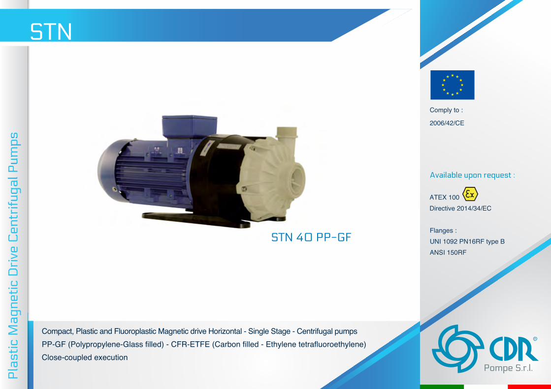
Compact, Plastic and Fluoroplastic Magnetic drive Horizontal - Single Stage - Centrifugal pumps PP-GF (Polypropylene-Glass filled) - CFR-ETFE (Carbon filled - Ethylene tetrafluoroethylene) Close-coupled execution Plastic Magnetic Drive Centrifugal Pumps STN R Pompe S.r.l. Comply to : 2006/42/CE Available upon request : ATEX 100 Directive 2014/34/EC Flanges : UNI 1092 PN16RF type B ANSI 150RF STN 40 PP-GF
Transcript of Plastic Magnetic Drive Centrifugal Pumps -...
Compact, Plastic and Fluoroplastic Magnetic drive Horizontal - Single Stage - Centrifugal pumpsPP-GF (Polypropylene-Glass filled) - CFR-ETFE (Carbon filled - Ethylene tetrafluoroethylene)Close-coupled execution
Pla
stic
Mag
netic
Dri
ve C
entr
ifuga
l Pum
ps
STN
R
Pompe S.r.l.
Comply to :
2006/42/CE
Available upon request :
ATEX 100 Directive 2014/34/EC
Flanges :UNI 1092 PN16RF type B
ANSI 150RF
STN 40 PP-GF
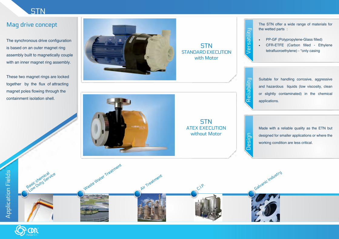
Made with a reliable quality as the ETN but
designed for smaller applications or where the
working condition are less critical.
Des
ign
Rel
iabi
lity Suitable for handling corrosive, aggressive
and hazardous liquids (low viscosity, clean
or slightly contaminated) in the chemical
applications.
Ver
satil
ity
The STN offer a wide range of materials for the wetted parts :
• PP-GF (Polypropylene-Glass filled)• CFR-ETFE (Carbon filled - Ethylene
tetrafluoroethylene) - *only casing
App
licat
ion
Fiel
ds
Basic chemical
Low Duty Service
Waste Water T
reatment
Air Treatm
ent
C.I.P.
Galvanic Industry
R
Pompe S.r.l.
Mag drive concept
The synchronous drive configuration
is based on an outer magnet ring
assembly built to magnetically couple
with an inner magnet ring assembly.
These two magnet rings are locked
together by the flux of attracting
magnet poles flowing through the
containment isolation shell.
STN STANDARD EXECUTION
with Motor
STN
STN ATEX EXECUTION
without Motor

www.cdrpompe.it
Inner and Outer magnets are equipped with
rare earth permanent magnets.
Patented cage magnet attachment guarantees
stability during the operation of the pump.
The STN are available in close coupled execution,
suitable to be coupled with standard electrical motors.
High chemical resistance employing a
performing material as CFR-ETFE.
• Alternative available materials
for the Wetted parts: PP.
The casing’s design is reinforced by a
solid rib structure.
Sealless design
Total containment, essential for
hazardous, aggressive or valuable
product.
3D VIEW

R
Pompe S.r.l.
FEATURES
SHAFT
• Axial and radial loads are well
distributed thanks to the highly reliable
rotating parts design. The static shaft
(SiC or Ceramic) is supported in the
can and by the lining suction cover.
ISOLATION SHELL
• ETFE Non-metallic double
Isolation Shell configuration on
wet side, externally reinforced by a
Polycarbonate can
As alternative, it is available made by
a solid 3 mm PP-GF layer
• Zero Eddy Current Losses
thanks to non-metallic execution
IMPELLER ASSEMBLY
• The integral design of the impeller
and inner magnet prevents any
misalignment problem, also reducing
the production cost
• Standard back vanes reduce axial
thrust and seal chamber pressures to
guarantee an extraordinary bearing
and seal life.
CASING
• Available in CFR-ETFE and PP-GF execution
• Standard casing drain for a complete
and fast draining of the casing

www.cdrpompe.it
PERFORMANCE FIELDS5
0H
z
m
Q m3\h
H
3500rpm
0
2
6 8 10 12 14 16 2042
6
10
14
18
22
26
30
24 28
stn 40stn 30
m
Q m3\h
H
1450rpm
0 6 8 10 12 14 16 1842
0.8
1.6
2.4
3.2
4.0
4.8
5.6
6.4
7.2
stn 40stn 30
m
Q m3\h
H
1750rpm
0 6 8 10 12 14 16 1842
1
2
3
4
5
6
7
8
9
stn 40stn 30
60
Hz
m
Q m3\h
H
2900rpm
0
2
6 8 10 12 14 16 2042
6
10
14
18
22
26
30
24 28
stn 40stn 30
Not binding data refers to water at room temperature. For specific performance curve contact CDR Pompe Srl.
R
Pompe S.r.l.
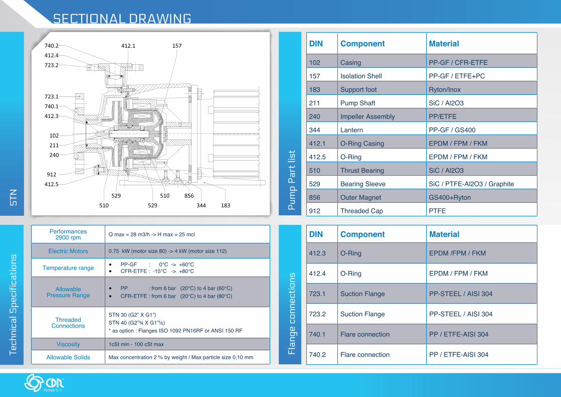
SECTIONAL DRAWING
Pum
p P
art
list
DIN Component Material
102 Casing PP-GF / CFR-ETFE
157 Isolation Shell PP-GF / ETFE+PC
183 Support foot Ryton/Inox
211 Pump Shaft SiC / Al2O3
240 Impeller Assembly PP/ETFE
344 Lantern PP-GF / GS400
412.1 O-Ring Casing EPDM / FPM / FKM
412.5 O-Ring EPDM / FPM / FKM
510 Thrust Bearing SiC / Al2O3
529 Bearing Sleeve SiC / PTFE-Al2O3 / Graphite
856 Outer Magnet GS400+Ryton
912 Threaded Cap PTFE
Performances 2900 rpm Q max = 28 m3/h -> H max = 25 mcl
Electric Motors 0.75 kW (motor size 80) -> 4 kW (motor size 112)
Temperature range • PP-GF : 0°C -> +60°C• CFR-ETFE : -15°C -> +80°C
Allowable Pressure Range
• PP : from 6 bar (20°C) to 4 bar (60°C)• CFR-ETFE : from 6 bar (20°C) to 4 bar (80°C)
Threaded Connections
STN 30 (G2” X G1”)STN 40 (G2”¾ X G1”½)* as option : Flanges ISO 1092 PN16RF or ANSI 150 RF
Viscosity 1cSt min - 100 cSt max
Allowable Solids Max concentration 2 % by weight / Max particle size 0,10 mmTech
nica
l Spe
cific
atio
ns
Flan
ge c
onne
ctio
ns
DIN Component Material
412.3 O-Ring EPDM /FPM / FKM
412.4 O-Ring EPDM / FPM / FKM
723.1 Suction Flange PP-STEEL / AISI 304
723.2 Suction Flange PP-STEEL / AISI 304
740.1 Flare connection PP / ETFE-AISI 304
740.2 Flare connection PP / ETFE-AISI 304
STN

www.cdrpompe.it
OVERALL DIMENSIONS
STN 30/40 moTor Size 80/90 ... STN 30/40 moTor Size 100/112 ...
model DNa DNm da dm a (mm)
b (mm)
h1 (mm)
L (mm)
f1 (mm)
m (mm)
n (mm)
motor Frame
STN 3040 20 G 2'' G 1'' 60 63 100 438 173 180 200 100 B3 / B14
40 20 G 2'' G 1'' 60 70 112 443 173 190 240 112 B3 / B14
STN 4050 32 G 2 -3/4'' G 1-1/2'' 67 63 100 443 173 180 200 100 B3 / B14
50 32 G 2-3/4'' G 1-1/2'' 67 70 112 450 173 190 240 112 B3 / B14
model DNa DNm da dm a (mm)
L (mm)
motor Frame
STN 30 40 20 G 2'' G 1'' 60 370 80 / 90 B5
STN 40 50 32 G 2 3/4'' G 1 1/2'' 67 377 80 / 90 B5
FLaNgeD execuTioN...STN 30/40 moTor Size 80/90 ...
STN 30/40 moTor Size 100/112 ...
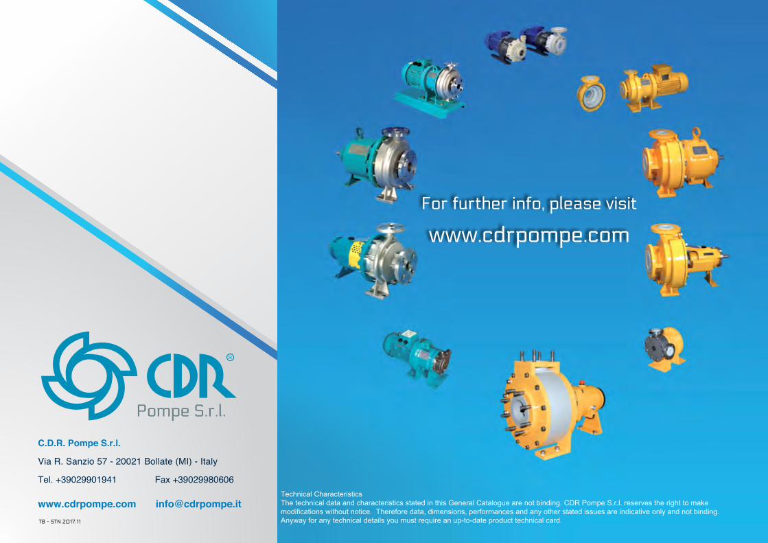
C.D.R. Pompe S.r.l.
Via R. Sanzio 57 - 20021 Bollate (MI) - Italy
Tel. +39029901941 Fax +39029980606
www.cdrpompe.com [email protected]
R
Pompe S.r.l.
For further info, please visit
www.cdrpompe.com
Technical CharacteristicsThe technical data and characteristics stated in this General Catalogue are not binding. CDR Pompe S.r.l. reserves the right to make modifications without notice. Therefore data, dimensions, performances and any other stated issues are indicative only and not binding. Anyway for any technical details you must require an up-to-date product technical card.TB - STN 2017.11


![Untitled-1 []...FRP Compression Molding Rotational Molding Skiving Thermal Forming CONTRACT: Fluoroplastic Etching CNC Machining PRODUCTS PTFE, PGA, FEP, PUDF & POLYPRO: Hose & Fittings](https://static.fdocuments.us/doc/165x107/5ebb6451aa66ba72592dcdc4/untitled-1-frp-compression-molding-rotational-molding-skiving-thermal-forming.jpg)