PLASTIC FILM CAPACITOR
34
Ver.7 (July.06, 2011) - 1 - PLASTIC FILM CAPACITOR TECHNICAL GUIDE Panasonic Electronic Devices Japan Co., Ltd. Film Capacitor Division
Transcript of PLASTIC FILM CAPACITOR

Ver.7 (July.06, 2011)
- 1 -
PLASTIC FILM CAPACITOR TECHNICAL GUIDE
Panasonic Electronic Devices Japan Co., Ltd. Film Capacitor Division
Ver.7 (July.06, 2011)
- 2 -
CONTENTS 1. Preface 2. Principle of capacitors 3. Type of capacitors and their features 4. Structure and features of film capacitors 5. Standard production processes of film capacitors 6. Cause of failure and failure mode of film capacitors 7. Cautions for using film capacitors
7.1 Voltage 7.2 Current 7.3 Temperature 7.4 Humidity
8. Life estimation of film capacitors 9. Points for mounting
9.1 Soldering 9.2 Automatic mounting
9.3 Cautions for handling
9.4 Solvent resistivity
9.5 Resin coating
10.Storage and preservation
11.Others
This technical guide is written for the customers who use film capacitors at present and are considering using them to facilitate their circuit design/part selection with the information of film capacitors such as the features and cautions. Please confirm the guarantee information in delivery specifications or confirmation for usage conditions issued by our firm when using film capacitors, as this technical guide does not cover them. (This contract is to be valid with exchange of delivery specifications. We appreciate you understand in advance that
this technical guide does not have guarantees.)

Ver.7 (July.06, 2011)
- 3 -
1. Preface
As capacitors are one of the main electronic parts composing electronic circuit, various type of capacitors and developed and used.
This technical guide offers summarized application for techniques for film capacitors that are widely used for a variety of electronic equipment.
A selection of capacitor type should be done considering featuring points of the circuit. As a rule, as shown in Fig.1., selection will be made taking capacitance and withstand voltage into consideration. If some types share the features, give the priority to performance such as frequency characteristics, reliability and cost etc..
Our firm prepares a lot of products to respond to customer’s requests. However, as capacitors(in particular, film capacitors) are sensitive to usage condition, it is recommended to refer to this technical guide before use. Advanced inquiries about technical matters will be also appreciated.
:Stacked metallized film chip capacitors :Film capacitors Note) This chart shows just a typical example. Capacitors with capacitances and rated voltages other than
this chart are also available. Fig.1. Capacitances and rated voltages for various capacitors.
6.3
10
16
25
35
50
100
250
500
1pF 1000pF 1µF 1000 µF 1F Withstand voltage
Tantalum capacitorsElectric double layer capacitors
Aluminum electrolytic capacitors (Small size)
Disk type ceramic capacitors
Medium and high voltage ceramic capacitors
4
Multi layer ceramic capacitors
Film capacitors
Aluminum electrolytic capacitors (large size)
Functional polymer molecule
Stacked metallized film chip capacitors
15K

Ver.7 (July.06, 2011)
- 4 -
2. Principle of capacitors
When two plane electrodes are set face to face and electric field is applied between them, electric charge proportional to the field flows instantaneously and stored between the electrodes.
Electronic parts called capacitor or condenser apply the above phenomenon that electric charge is stored between two electrodes and the structure of which is designed to facilitate the storage of charge. Capacitors can make rapid and repeated charge and discharge of electric charge.
They also have a function that stops D.C.current and passes A.C.current. Using this characteristics, capacitors are applied in electronic circuit in combination with resistors and coils(inductance).
Fig.2. Principle of capacitors 3. Type of capacitors and their features
Capacitors are classified into two types, fixed ones(fixed capacitance) and variable ones(variable capacitance). Fixed capacitors are further classified according to dielectric materials used. Typical fixed capacitors and their features are shown in Fig.3. and Table 1., respectively.
Fig.3. Typical classification of fixed capacitors according to type of dielectric materials
○+
○+
○+
○+
○+
○+
○-
○-
○-
○-
○-
○-
+
+
+
+
+
+
+
+
+
+
+
+
+
+
-
-
-
-
-
-
-
Negative charge Polarized charge
Positive charge
Load
Discharge
sw
- +
Charge
Metal electrode
Film capacitors
Ceramic capacitors
Aluminum electrolytic capacitors
Tantalum electrolytic capacitors
Electric double layer capacitors
Others(mica capacitors, paper capacitors)
Fixed capacitors

Ver.7 (July.06, 2011)
- 5 -
Table 1. Features of typical capacitors
Type Item Film capacitors Ceramic capacitors Tantalum electrolytic
capacitors Aluminum electrolytic
capacitors Dielectric
・Polyethylene terephthalate(PET)
・Polypropylene(PP) ・Polyethylene
naphthalate(PEN) ・Polyphenylene
sulfide(PPS) ・Thermo-setting plastic
etc.
・Titanium oxide ・Barium titanate
etc.
・Tantalum pentoxide
・Aluminum oxide
Merits
・Small temperature dependence of capacitance
・Small frequency dependence of capacitance
・Precise capacitance tolerance
・Nonpolarity and applicable to A.C. and D.C..
・Low dissipation factor and suitable for high frequency use
・High insulation resistance
・High reliability
・Small size ・High reliability ・Nonpolarity ・Good frequency
characteristics
・Small size ・Large capacitance ・Long life
・Large capacitance
Demerits
・Comparatively large size
・Comparatively low temperature resistance
・Small capacitance range
・Capacitance change due to temperature and applied voltage
・Polarity ・Large ESR
・Polarity ・Large ESR ・Limited life
Capacitance
range (approximate)
100pF ~ 20uF
Chip:100pF~1.0µF
0.5pF ~ 10uF
0.01uF ~ 470uF
0.10uF ~ 1.0F
Rated voltage (approximate)
10V ~ 35kV
Chip:10V~250V
16V ~ 15kV
2V ~ 125V
4V ~ 500V
Main use
・CR time constant circuit
・By-pass circuit ・Coupling circuit ・Resonance circuit ・Filter ・Snubber circuit
・Oscillator, tuning ・CR time constant
circuit ・By-pass circuit ・Coupling circuit ・Noise limiter
・CR time constant circuit
・By-pass circuit ・Coupling circuit ・Noise limiter
・By-pass circuit ・Coupling circuit ・Rectifying circuit
Ver.7 (July.06, 2011)
- 6 -
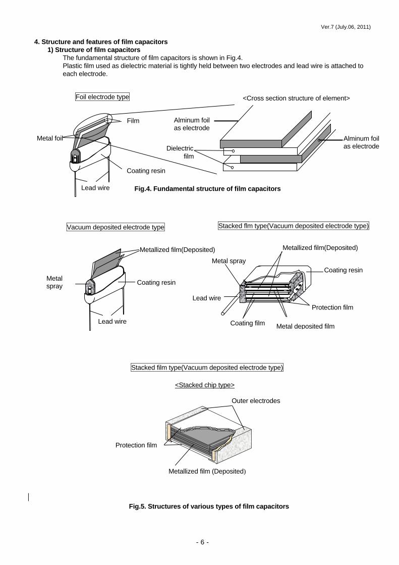
4. Structure and features of film capacitors 1) Structure of film capacitors
The fundamental structure of film capacitors is shown in Fig.4. Plastic film used as dielectric material is tightly held between two electrodes and lead wire is attached to each electrode.
Lead wire
Coating resin
Lead wire
Metal spray
Metallized film(Deposited)
Film
Metal foil
Coating resin
Foil electrode type
Vacuum deposited electrode type
Fig.5. Structures of various types of film capacitors
Dielectric film
Fig.4. Fundamental structure of film capacitors
Alminum foilas electrode
Stacked flm type(Vacuum deposited electrode type)
Coating resin
Protection film
Metal deposited filmCoating film
Lead wire
Metal spray
Protection film
Outer electrodes
<Stacked chip type>
Stacked film type(Vacuum deposited electrode type)
<Cross section structure of element>
Alminum foilas electrode
Metallized film(Deposited)
Metallized film (Deposited)

Ver.7 (July.06, 2011)
- 7 -
Table2. Types of element structure/dielectric material of film capacitors
Foil type
Metallized film type
Elem
ent s
truc
ture
D
iele
ctric
mat
eria
l
Poly
este
r
ECQE(B) ECQE(F) ECQE(T)
Safety standard approved ECQUL ECQUG(※Only 3A) ECQUY
ECWU(X) ECWU(C) Chip type (PEN film)
Poly
prop
ylen
e
ECWF(A) ECWF(L) ECWH(A) ECWH(C) ECWH(V)
Safety standard approved ECQUA
PPS
ECHU(X) ECHU(C) Chip type
Com
posi
te d
iele
ctric
s ECQV(L) ECQV(M)
Wound Stacked

Ver.7 (July.06, 2011)
- 8 -
2) Features of film capacitors Film capacitors with plastic film with high electric insulation have general features shown below.
(1) Small temperature dependence of capacitance. (2) Small capacitance tolerance products are available(+1%). (3) Applicable to both A.C. and D.C. due to nonpolarity. (4) Because of low dissipation factor(tanδ), suitable for high frequency application. (5) Because of high insulation resistance, suitable for high impedance circuit. (6) Small bias characteristics(small capacitance change due to applied voltage variation).
Basic characteristics of each type of capacitors are shown below. 2)-1 Temperature characteristics Temperature dependence of capacitance, dissipation factor (tanδ ) and insulation resistance.
Fig.6
2)-2 Frequency characteristics Frequency dependence of capacitance, dissipation factor(tanδ) and insulation resistance.
2)-3 Bias characteristics Capacitance change due to applied voltage variation.
Fig.7
Fig.8
ex. Polyester capacitors
Capacitance change Dissipation factor changeInsulation resistance change
Impedance characteristicsDissipation factor changeCapacitance change
Capacitance change rate
Bias voltage (Vdc)

Ver.7 (July.06, 2011)
- 9 -
5. Standard manufacturing process of film capacitors [Foil electrode type]
Alternatively film and aluminum foil are wound to be four sheets in all.
Lead wire
connection C
oating/ Indication
Electric inspection
Shipping
Wound element is formed to be flat shape by heat-press aging.
Lead wire is connected to protruding aluminum by soldering or welding.
Element is coated with epoxy resin. Voltage, capacitance, etc. are indicated on the coated surface.
Withstand voltage, capacitance, dissipation factor, insulation resistance, etc. are checked for 100% of the capacitors.
Shipping
Film
Aluminum foil
Packing
Completed capacitors are packed by specified number,
Press aging W
inding
Core

Ver.7 (July.06, 2011)
- 10 -
[Vacuum deposited electrode type]
Winding
Alternatively film and vacuum deposited film are wound to be four sheets in all.
Pressing M
etal spray Voltage treatm
entLead w
ire connection
Wound element is formed to be flat shape by heat pressing.
Metal is sprayed on both ends of element to form electrodes to connect inner electrodes with lead terminals.
Lead wire is connected to sprayed metal layer by welding.
Vacuum
deposition Slitting
Vacuum deposited film is cut to have each settled width.
Aluminum is vacuum deposited on film.
Coating/
Indication Packing
Shipping Electric
inspection
Withstand voltage, capacitance, dissipation factor, insulation resistance, etc. are checked for 100% of the capacitors.
Completed capacitors are packed by specified number,
Shipping
Deteriorated insulation resistance portion is removed by applying a certain value of voltage.
Element is coated with epoxy resin. Voltage, capacitance, etc. are indicated on the coated surface.
Core
Metallic spray

Ver.7 (July.06, 2011)
- 11 -
[Stacked vacuum deposited electrode type]
Element is coated with epoxy resin. Voltage, capacitance, etc. are indicated on the coated surface.
Wide w
idth w
inding
Lacquered wide width film is wound around a flat bobbin.
Pressing
Voltage treatment
Coating/
Indication
Wound flat stacked plate is heat pressed and formed
Metal is sprayed on both ends of stripe to form electrodes to connect inner electrodes with lead terminals.
A certain value of voltage is applied.
Vacuum
deposition Lacquering
Deposited film is lacquered with dielectric material.
Aluminum is vacuum deposited on film.
PackingShipping
Electric inspection
Withstand voltage, capacitance, dissipation factor, insulation resistance, etc. are checked for 100% of the capacitors.
Completed capacitors are packed by specified number.
Shipping
Slitting
After both wound edges of the flat plate are cut off, the plate is slit into stripe like capacitors.
Lead wire is connected to sprayed metal layer by welding.
Cutting
Stripe capacitor is cut into individual capacitors to have required capacitance.

Ver.7 (July.06, 2011)
- 12 -
6. Cause of failure and failure mode of film capacitors Film capacitors are one of the electronic parts with highest reliability. However, according to the manner of use,
failures shown in Table3 might occur. Table3. Cause of failure and failure mode of film capacitors
Failure mode Cause of failure Failure position Foil type Metallized type [Voltage] ・Application of high pulse voltage(surge of thunder etc.) ・Application of over rated voltage(Connection miss to power source etc.)
・Penetrated breakdown from the weakest position ・Penetrated breakdown from the weakest position ・Inherent temperature rises because applied current decreases withstand voltage and results in penetrated breakdown.
Short
Short
Short
Decrease of insulation resistance
(Note1)Decrease of insulation resistance Decrease of insulation resistance
[Current] ・Flow of high pulse current(charge-discharge circuit etc.) ・Flow of high frequency and high current(Resonance circuit etc.)
・Connection of metal sprayed part with deposited metal rapidly generates heat. The deposited metal vaporize and the connection become unstable. ・Inherent temperature rises because applied current decreases withstand voltage of film and results in voltage breakdown. Also heat shrinkage of the film causes unstable connection of electrodes.
Short (Open)
Open
Decrease of insulation resistance
(Short)
・Heat shrinkage of film causes unstable connection of electrodes due to the heat in mounting. ・Rapid heating causes expansion of inner volume of capacitors and coating cracks.
Capacitance change
Open Decrease of withstand current
Coating cracks
Open
Decrease of withstand current
Coating cracks
[Temperature] ・ Mounting temperature (Heat influence in
mounting)
・ High temperature ambience (Heat from surrounding parts etc.)
・High temperature decreases withstand voltage of film and results in voltage breakdown or heat shrinkage of the film causes unstable connection.
Short
Open
Decrease of insulation resistance
(Short)
Open [Humidity] ・High humidity ambience
・Humidity absorption of film decreases withstand voltage of film and results in voltage breakdown. ・Capacitance decreases because hydrolysis caused by absorbed moisture make deposited metal insulator.
Short
―――――
Decrease of insulation resistance
(short)
Decrease of capacitance
(Toward Open) (Note1) Using capacitors with insulation resistance of element decreased may causes surge of current and inherent temperature of capacitors rises, which results in decrease of withstand voltage and voltage breakdown. As a result, the process; Decrease of insulation resistance→Heat generating→Decrease of withstand voltage→voltage breakdown is repeated. Moreover, there may be ignition or smokes caused by film melting in capacitors due to the heat.

Ver.7 (July.06, 2011)
- 13 -
7. Cautions for using film capacitors 7.1 Voltage
(1)D.C. voltage D.C. rated voltage is principally determined by the thickness and kind of dielectric material. In case of pure
D.C. without ripple, full rated voltage can be applied to capacitors. However, for using under high temperature or due to inherent temperature rise by included ripple components and ripple current, voltage derating by is necessary. (Refer to 7.4) (2)A.C. voltage
A rated voltage of capacitor is normally defined as D.C. rated voltage. In case that film capacitor are used under A.C. voltage, occur heating and corona discharge, use permissible voltage in alternating current lower than that shown in Table 4. However, this Table is not applicable for some products, in that case, refer to individual product specifications.
Table4. D.C. voltage and permissible voltage in alternating current (50/60Hz)
Type D.C. rated voltage (DC)
Permissible voltage (r.m.s) in alternating
current ECQV(L) 50 V 40 V
63 V 40 V ECQV(M)
100 V 63 V 100 V 63 V 250 V 150 V 400 V 200 V 630 V 250 V
1000 V 400 V
ECQE(F)
1250 V 500 V ECQE(B) 250 V 125 V
250 V 150 V 400 V 200 V ECQE(T)
630 V 250 V ECWF(A) 250 V 125 V
400 V 141 V 450 V 160 V ECWF(L) 630 V 223 V
ECWH(A) 800 V 283 V 1000 V 283 V 1250 V 354 V 1600 V 425 V ECWH(V)
2000 V 531 V (3)Considerations for pulse voltage(In case of low effective value of current and low inherent temperature.) In principle, using within D.C. rated voltage is applicable. The followings can be taken into account. For metallized capacitors, however, use below permissible pulse current(dV/dt value). 1.Pulse frequency below 10 times a year ――Applicable up to withstand voltage ・Metallized type ―――――――――――1.5 times of rated voltage 2.Pulse frequency below 10 times a day ―― Applicable up to the level of life test ・Metallized tyoe ――――――――――――1.25 times of rated voltage

Ver.7 (July.06, 2011)
- 14 -
(4)Considerations for high frequency voltage(In case of high effective value of current with heat) –Voltage with high frequency beyond commercial frequency)
When high frequency voltage is applied to film capacitors, current shown by the following equation flows and results in inherent heating of capacitors. For details, refer to item of High current.
I = 2 ・ π ・f ・ C ・ V I : Current that flows capacitors (Arms) π: 3.14 f : Applied frequency (Hz) C : Capacitance (F) V : Applied voltage (Vrms) 7.2 Current
Permissible current needs to meet both pulse current and continuous current that should be considered separately with breakdown mode.
(1)Considerations for pulse current(In case of low effective value of current and low inherent temperature)
Though capacitors can accept high current through abrupt charge and discharge, there are some types that need current restriction according to element structure.
Foil type capacitors have high endurance to pulse current because lead wire is welded or soldered to foil electrode.
However, metallized type has extraction electrodes which deposited film and melting metal are applied to(known as Metallicon, hereinafter referred as Metallicon), which brings the need of pulse current restriction to metallized type because deposited film and metal sprayed electrodes have contact resistance which brings heat generation by high pulse current and deposited film vaporize and is removed. Eventually capacitors show an open failure.
To regulate this, dV/dt (V/µs) is generally used and the concept is shown below.
・When a voltage V(V) is applied to a capacitor of C(F), electric charge in the capacitor is expressed by equation (1).
Q = C ・ V ------------ Equation (1) ・The charging current I(A) is expressed by equation (2). I = dQ/dt ------------ Equation (2) ・By differentiating both sides of equation (1) by time t and substituting into equation (2), it is transformed
as equation (3). dQ/dt = C ・ dV/dt I = C ・ dV/dt ------- Equation (3)
That is, the term dV/dt expresses the variation rate of voltage against time on charging or discharging and pulse current is calculated by the product of dV/dt value and capacitance. Therefore, permissible pulse current can be expressed by dV/dt value.
(1)Specified dV/dt
dV/dt of metallized type is shown in Table.5 to 7.
(2)Breakdown mode caused by pulse current(dV/dt) With surge of pulse current beyond permissible values, heating occurs on contact resistance of deposited film of inner electrodes and metallicon, and the deposited film rapidly vaporize and is removed. As the failure mode, increase of dissipation factor(tanδ ) and decrease of capacitance occur to both wound and stacked type. However, the processes to the failure differ depending on the structures of wound and stacked type. A model of failure mechanism is shown inTable 9.

Ver.7 (July.06, 2011)
- 15 -
Fig.9. Failure mechanism by pulse current (3)Cautions for selecting pulse current
For applying pulse current, be sure that dV/dt value(pulse current) is within the one indicated in Table 5, 6 and 7. If not, check them in product specifications before use. In case that the value for metallized type exceeds a permissible one, an inquiry to us.
Film
Deposited film Film
Deposited film
Application of pulse current
Heating due to contact resistance between metallicon and deposited film
Vaporization of deposited film
(Refer to Figure)
Increase of tanδ
Decrease of capacitance
Disconnection at the deposited film due to localized pulse current
《Wound type》 《Stacked type》
Disconnection of stacked layer

Ver.7 (July.06, 2011)
- 16 -
Table5. Permissible dV/dt value of ECQV(L) series
Calculation of permissible pulse current Permissible pulse current can be calculated by the product of nominal capacitance(µs) shown below and
permissible dV/dt value. ( Example: Permissible pulse current of 104 Iop=0.1 × 32 = 3.2Aop Total number of application is less than 10000)
Capacitance (Nominal capacitance:µF)
Permissible dV/dt value (V/µs) (at 10000 times)
1 0 3 (0.010) 1 2 3 (0.012) 1 5 3 (0.015) 1 8 3 (0.018) 2 2 3 (0.022) 2 7 3 (0.027) 3 3 3 (0.033) 3 9 3 (0.039) 4 7 3 (0.047) 5 6 3 (0.056) 6 8 3 (0.068) 8 2 3 (0.082)
3 7
1 0 4 (0.10) 1 2 4 (0.12) 1 5 4 (0.15) 1 8 4 (0.18) 2 2 4 (0.22) 2 7 4 (0.27) 3 3 4 (0.33) 3 9 4 (0.39) 4 7 4 (0.47) 5 6 4 (0.56) 6 8 4 (0.68) 8 2 4 (0.82) 1 0 5 (1.0)
3 2
1 2 5 (1.2) 1 5 5 (1.5) 1 8 5 (1.8) 2 2 5 (2.2)
1 2
Ver.7 (July.06, 2011)
- 17 -
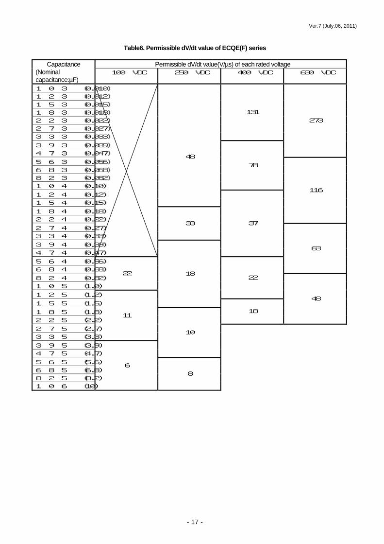
Table6. Permissible dV/dt value of ECQE(F) series
Permissible dV/dt value(V/µs) of each rated voltage Capacitance
(Nominal capacitance:µF)
100 VDC 250 VDC 400 VDC 630 VDC
1 0 3 (0.010) 1 2 3 (0.012) 1 5 3 (0.015) 1 8 3 (0.018) 2 2 3 (0.022) 2 7 3 (0.027) 3 3 3 (0.033)
131
3 9 3 (0.039) 4 7 3 (0.047)
273
5 6 3 (0.056) 6 8 3 (0.068) 8 2 3 (0.082) 1 0 4 (0.10)
78
1 2 4 (0.12) 1 5 4 (0.15)
48
1 8 4 (0.18) 2 2 4 (0.22)
116
2 7 4 (0.27) 3 3 4 (0.33)
33
3 9 4 (0.39) 4 7 4 (0.47)
37
5 6 4 (0.56) 6 8 4 (0.68)
63
8 2 4 (0.82) 1 0 5 (1.0)
22
1 2 5 (1.2)
22
1 5 5 (1.5)
18
1 8 5 (1.8) 2 2 5 (2.2)
18
48
2 7 5 (2.7) 3 3 5 (3.3)
11
3 9 5 (3.9) 4 7 5 (4.7)
10
5 6 5 (5.6) 6 8 5 (6.8) 8 2 5 (8.2) 1 0 6 (10)
6 8
Ver.7 (July.06, 2011)
- 18 -
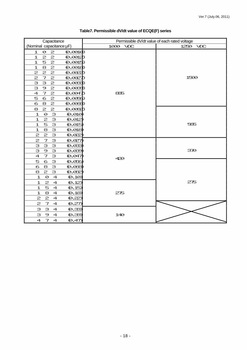
Table7. Permissible dV/dt value of ECQE(F) series
Permissible dV/dt value of each rated voltage Capacitance (Nominal capacitance:µF) 1000 VDC 1250 VDC
1 0 2 (0.0010) 1 2 2 (0.0012) 1 5 2 (0.0015) 1 8 2 (0.0018) 2 2 2 (0.0022) 2 7 2 (0.0027) 3 3 2 (0.0033) 3 9 2 (0.0039) 4 7 2 (0.0047) 5 6 2 (0.0056) 6 8 2 (0.0068)
1500
8 2 2 (0.0082) 1 0 3 (0.010) 1 2 3 (0.012) 1 5 3 (0.015) 1 8 3 (0.018) 2 2 3 (0.022)
885
565
2 7 3 (0.027) 3 3 3 (0.033) 3 9 3 (0.039) 4 7 3 (0.047)
370
5 6 3 (0.056) 6 8 3 (0.068) 8 2 3 (0.082) 1 0 4 (0.10)
420
1 2 4 (0.12) 1 5 4 (0.15)
1 8 4 (0.18) 275 2 2 4 (0.22)
275
2 7 4 (0.27)
3 3 4 (0.33) 3 9 4 (0.39) 140 4 7 4 (0.47)

Ver.7 (July.06, 2011)
- 19 -
(4)Case that pulse current value needs particular attention In using for inverter circuit for lighting equipment, igniters for gas hot water system or gas
appliance and CDI etc., particular attention should be given to pulse current. In addition, for those equipment, select a capacitor with confirmation that the use conditions of
the equipment such as pulse current, pulse voltage and number are within product specifications. Example : Power Supply circuit(Inverter power etc.)
Switching element brings pulse generation in snubber circuit to generate high frequency. Film
capacitors remove noise in switching. Pulse current flows continuously due to constant switching in snubber circuit. Therefore, please use a
high pulses capacitor. In addition, for capacitors used in resonance circuit, use with confirmation of pulse current in each state within stipulated range because higher voltage is applied when starting equipments, changing and ending lamps(lamps deterioration, flickering).
【Starting】 【Changing lamps】
Pulse current flows when starting or changing lamps if lighting equipment is used. Generally, permissible number of pulse application is 10000. Do not apply more than the permissible
number of times of application because the pulse current is applied until equipment can not be used. For metallized capacitors such as ECWF and ECWH etc. used in resonance circuit, pay attention
because pulse current and voltage are applied not only due to continuous current in lightning, other factors such as abnormality as well.
Snubber circuit
Resonance circuit
Smoothing circuit

Ver.7 (July.06, 2011)
- 20 -
(2)Considerations for high frequency(In case of heating by effective current) Capacitors can generate heat with high frequency. Check the inherent temperature, which is the best method
to judge operating conditions because capacitors are used applying various wave-form current. As heating varies according to dissipation factor, which brings difference of permissible inherent temperature rise, be sure to use them below the upper limit shown in Table8.
Table8. Upper limit of inherent temperature rise
(1)Mechanism of inherent heating
Heating of capacitors(ΔT) are associated with flowing current I(Arms) and equivalent series resistance(ESR) of the capacitor.
ΔT ∝ ESR × Irms2 ------ Equation(4)
(Equivalent series resistance: Series resistance by film characteristics, Lead wire resistance, Contact
resistance of metallicon, Electrode resistance) Check the ambient temperature as well, because of dependence on temperature of equivalent series
resistance. (2)Frequency and permissible current value
As shown in equation(4), inherent temperature rise is proportional to square of effective value of current and equivalent series resistance. The correlation of frequency and permissible current value can be shown below.
Equation(4) is transformed as equation(5). ΔT Irms ∝ ------ Equation(5)
ESR
As a result, permissible current value is associated with reciprocal of equivalent series
resistance(ESR) which varies according to frequency and brings different permissible current value. Use them below the permissible current value of each frequency shown in Fig.12, 13, 14 and Table9. For products that are not mentioned, check the each product specification.
Dissipation factor and structure Upper limit of inherent temperature rise (at 25 degree C of ambient temperature)
Polyester film capacitors 10 degree C PPS film capacitors 10 degree C
ECWF(A) 19 degree C ECWF(L) 8 degree C
Polypropylene film capacitors
ECWH(A), (V) 20 degree C TF capacitors(ECQV) 10 degree C
ESR

Ver.7 (July.06, 2011)
- 21 -
(3)Test method of inherent temperature rise
A surface temperature of capacitor and the ambient temperature shall be measured by attaching a thermocouple on the surface not to receive radiation heat from surrounding parts(When there are many components near the capacitor, the capacitor receive radiation heat. In case that , the capacitor shall be put opposite side from them etc.) as shown in Fig.10(At normal temperature). Use a thermocouple with small heat capacity(φ0.1 T wire).
Test shall be carried out in no wind taking actions to avoid an influence of wind such as placing capacitor in a box etc.. Check the surface temperature when reaching at the temperature balance.
(4)Breakdown mechanism by high frequency current Breakdown may occur if inherent temperature rise exceeds the specified value and localized heat is
not radiated out, which eventually cause thermal positive feedback and high temperature. As withstand voltage of film deteriorates with the increase of temperature, dielectric breakdown of
film occurs, which causes decrease of insulation resistance value. In addition, there may be increase of current, high-heated capacitors and possibilities of ignition/smoking.
Breakdown mechanism is shown in Fig.11.
(5)Cautions for selecting capacitors for high frequency For using at frequency exceeding commercial one, be sure to use them below the permissible current
value of each frequency shown Fig.12, 13,14 and Table9. For products that are not mentioned, check the each product specification. For using at high frequency, in general, capacitors that have low inherent temperature rise(low tan
δ) such as PP and PPS are recommended.
Fig.10 Measurement method of inherent
In case of excess
inherent
temperature rise
over specified one.
Abnormal
heating due to
remained heat.
Decrease of
withstand voltage
of film due to
high temperature.
Decrease of
insulation
resistance due to
dielectric
breakdown of film
Danger of
ignition/smoking
due to further
temperature rise
Fig.11 Breakdown mechanism by continuous current
Temperature measuring instrument

Ver.7 (July.06, 2011)
- 22 -
Fig.12 Permissible current value of each frequency for ECQE(F)
Continuous(effective) current flowing through capacitors shall be below permissible value at each frequency.
However, reduce the current if the wall temperature of capacitor become over 85 degree C.
Derating of permissible current for operating temperature
*Derate the permissible current value if the wall temperature of capacitor become over 85 degree C as the following figure shows.
Wall temperature of capacitors(degree C)
Permissible current value of each frequency for 250 VDC - Sine wave
Red
uctio
n ra
te f
or p
erm
issi
ble
curre
ntan
d pu
lse
curre
nt(%
)

Ver.7 (July.06, 2011)
- 23 -
Fig.13 Permissible current value of each frequency for ECWF(L)
Continuous(effective) current flowing through capacitors shall be below permissible value at each frequency. However, reduce the current if the wall temperature of capacitor become over 85 degree C.
Permissible current value of each frequency for 400 VDC - Sine wave
Derating of permissible current for operating temperature
*Derate the permissible current value if the wall temperature of capacitor become over 85 degree C as the following figure shows.
Wall temperature of capacitors(degree C)
Red
uctio
n ra
te f
or p
erm
issi
ble
curre
ntan
d pu
lse
curre
nt(%
)

Ver.7 (July.06, 2011)
- 24 -
Continuous(effective) current flowing through capacitors shall be below permissible value at each frequency.
However, reduce the current if the wall temperature of capacitor become over 85 degree C.
Fig.14 Permissible current value of each frequency for ECWH(V)
Derate the permissible current value if the wall temperature of capacitor become over 85 degree C as the following figure shows.
Permissible current value of each frequency for 1600VDC - Sine wave
Derating of permissible current for operating temperature
Wall temperature of capacitors(degree C) (including inherent temperature rise)
Red
uctio
n ra
te f
or p
erm
issi
ble
curre
ntan
d pu
lse
curre
nt(%
)

Ver.7 (July.06, 2011)
- 25 -
Table9. Permissible current value of each frequency for ECWH(V)
Permissible current value of each frequency(Pulse permissible current) Rated voltage :1600VDC (1200Vp.p) Operating temperature : -25~85 degree C (wall temperature) (Derating shown before shall be needed in case of over 85 degree C)
Permissible effective current value of the wave form above can be calculated follows.
Effective current value
Frequency
Capacity(µF)
Pulse permissible current (Ap.p)
Pulse permissible current (Ap.p) Frequency
Capacity(µF)
×current(peak to peak)
Ver.7 (July.06, 2011)
- 26 -
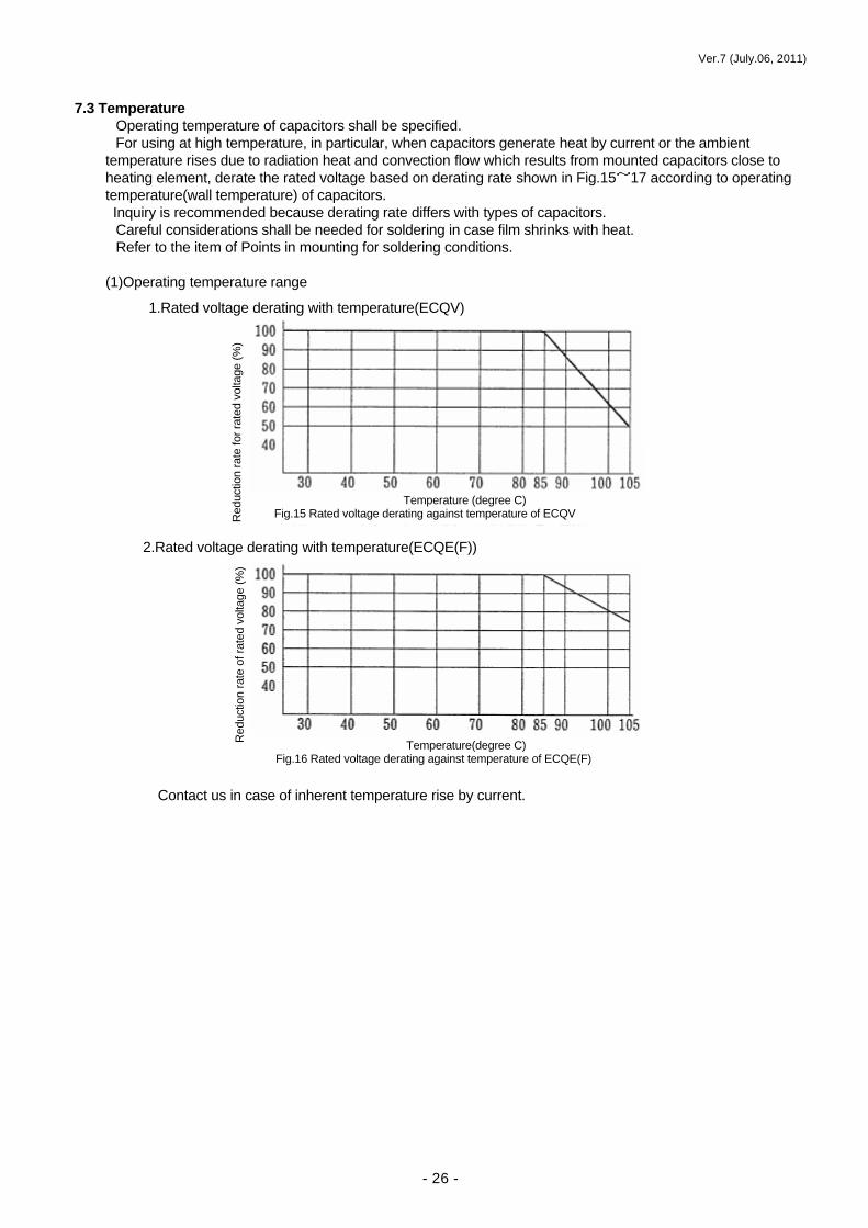
7.3 Temperature
Operating temperature of capacitors shall be specified. For using at high temperature, in particular, when capacitors generate heat by current or the ambient
temperature rises due to radiation heat and convection flow which results from mounted capacitors close to heating element, derate the rated voltage based on derating rate shown in Fig.15~17 according to operating temperature(wall temperature) of capacitors. Inquiry is recommended because derating rate differs with types of capacitors.
Careful considerations shall be needed for soldering in case film shrinks with heat. Refer to the item of Points in mounting for soldering conditions.
(1)Operating temperature range
Contact us in case of inherent temperature rise by current.
1.Rated voltage derating with temperature(ECQV)
2.Rated voltage derating with temperature(ECQE(F))
Temperature (degree C) Fig.15 Rated voltage derating against temperature of ECQV
Temperature(degree C) Fig.16 Rated voltage derating against temperature of ECQE(F)
Temperature(degree C) Fig.16 Rated voltage derating against temperature of ECQP, ECQF, WCQP(U)
Red
uctio
n ra
te o
f rat
ed v
olta
ge (%
) R
educ
tion
rate
for r
ated
vol
tage
(%)

Ver.7 (July.06, 2011)
- 27 -
7.4 Humidity (1)Capacitance change under normal temperature and humidity(normal environment)
Dielectric film absorbs water through coating of film capacitors, which results in increases of relative permittivity and capacitance.
Increasing rate of capacitance varies because moisture absorptance differs with types of film.
・Capacitance change through a year (left in normal temperature)
Type of capacitors Capacitance change(ΔC/C)
Polyester film capacitors About 1.5~3.0%
Polypropylene film capacitors About 0.5%
PPS film capacitors About 0.5~1.0%
(2)Influence of moisture absorption on capacitor characteristics As water has conducting properties, insulation resistance may decrease if capacitors absorb moisture. In
addition, further moisture absorption may cause losing of capacitor characteristics such as decrease of capacitance, increase of dissipation factor etc. due to corrosion of inner electrodes and derating of withstand voltage, and deterioration of capacitor performances at the end.
Therefore, appropriate measurements such as moisture-proof coating are required for using in high humidity.
Characteristic changes due to humidity absorption for each capacitor structure are shown in Fig.11.
Characteristics Metallized type Capacitance Capacitance decreases due to hydrolysis of deposited electrodes.
Insulation resistance
Insulation resistance significantly decreases.
Dissipation factor (tanδ)
Deposited film and metallicon corrode and significantly increase.
Withstand voltage
Withstand voltage of dielectric film decreases.
ΔC/C
Spring (Start of test)
Summer (High humidity)
Fall Winter (Dry period)
Spring
Fig.18 Capacitance change through a year (left in normal temperature)
Table10.Capacitance change value through a year (Japan)
Table11. Characteristic change due to humidity absorption
+
-

Ver.7 (July.06, 2011)
- 28 -
8. Life estimation of film capacitors Life of film capacitors can be estimated by a test accelerating factors such as temperature and voltage etc. that
influence on the life. 8.1 Life estimation by accelerated test
Thermal degradation of organic materials is supposed to follow the Arrhenius equation. Life estimation by accelerated test can be estimated by the equation2 using temperature and voltage acceleration.
(1)Equation for life estimation (2) List of voltage acceleration coefficient and temperature acceleration coefficient
Table12. List of voltage acceleration coefficient and temperature acceleration coefficient
Type Voltage acceleration coefficient : n
Temperature acceleration coefficient : θ
Stacked capacitors DC voltage 7 DC voltage 7 Metallized capacitors AC voltage 9
10
(3)Example of calculation
・In case of 60% of rated voltage and ambient temperature of 65 degree C. ・The specified life test condition for foil capacitor is that test temperature and test period are 1.4
times of rated voltage, 85 degree C and 1000 hours, respectively. ・By substituting these values into the life equation, the following result is obtained 0.6 -5 Ls = 1000× ――― × 2 1.25 Ls = 1000×(0.48) × 2 Ls ≒ 156983 h
VS -n -〔(TS-T0)/θ〕 LS =L0 × × 2 Equation2 V0
L0 : Test period LS : Estimated life V0 : Test voltage VS : Operating voltage T0 : Test temperature TS : Operaitng temperature n : Voltage acceleration coefficient(n≒5~9) θ : Temperature acceleration coefficient(θ≒10)
Life estimation ( Reference)
85-65 10
-5 2

Ver.7 (July.06, 2011)
- 29 -
Soldering period (sec.)
400
380
360
300
280
260
240
220
0 1 2 3 4 5 6 7 8
9. Points for mounting 9.1 Soldering (1) Thermal stress of capacitors due to soldering
Using lead-free solder allows thermal stress that arises when film capacitors with lead terminals are mounted on printed wiring board to be applied higher temperature than usual. In addition, thermal stress to parts notably differs with mounting methods. It should be noted that, although soldering temperature is about 250 degree C, part temperature may change significantly according to preheating conditions(temperature, period), heating methods, materials of printed wiring board and size of parts.
Fig.21. Recommended soldering conditions – film capacitors with lead terminals
As film capacitors with lead terminals are exclusive to flow mounting inserting in printed wiring board and soldering to bottom, not to reflow mounting. Our recommended soldering conditions are shown in Fig.21. Carry out flow mounting a total of 2 times, the second of which shall be done after capacitors become normal temperature. Soldering period of double-baths soldering equipment refers to a total of the first and the second baths. However, Fig.21. refers to the range of temperature/ period that cannot bring deterioration of capacitors, not the one showing to stable soldering. Conditions for stable soldering shall be set, checking respectively in the range above. Do not pass it through curing furnace with film chip parts in case there may be deterioration of characteristics.
(2)Temperature resistance of capacitors in mounting Temperature resistance of film capacitors differs with film materials, structure and manufacturing
methods. Although film chip capacitors are produced with considerations of heat resistance which brings high heat resistance, if the temperature of capacitor with lead wire exceeds the element temperature shown in Fig.13., there may be deterioration of characteristics and appearance abnormalities.
Mounting conditions shall be set below maximum element temperature shown in Fig.13. In addition, beware of thermal effects in particular in using of straight lead, because there may be a large difference in
200 150 100 50
200 150 100 50
(℃) (℃)
0 30 60 90 120 150 0 30 60 90 120 150
Preheating High
Middle
None
Shape small
Shape large
Fig.19. Element temperature change due to preheating
Period Period Fig.20. Element temperature change according to element size
Soldering iron Dip soldering
Conditions Printed wiring board:Through hole board t = over 0.8mm Preheating conditions
below120C, within 60 seconds Temperature of copper foil on the bottom of printer wiring board shall be measured.
Sold
erin
g te
mpe
ratu
re (℃
)

Ver.7 (July.06, 2011)
- 30 -
thermal stress due to the difference of the length of lead wire from solder bath between straight lead and processed(forming).
Table13. Resistance temperature of capacitors
Dielectric material Type Maximum element temperature
Polypropylene ECWF ECWH
110 degree C 110 degree C
Polyester ECQV ECQE
150 degree C 120degree C
・It should be noted that element temperature rises differently according to capacitor size. ・As polypropylene capacitors have lower heat resistance than other types in terms of performances, which may bring deterioration of characteristics when mounting directly on printed wiring board, measurements such as reducing thermal effects by processed lead can be required.
(3)Temperature measurement method of capacitors in mounting
①Preparing samples for measurement Make a hole of diameter of 0.2~0.3mm on the side and the upper part of the capacitor. Insert
thermocouple as thin as possible (φ0.1 T wire is recommended) into around metallicon of extraction electrodes and at the center of the capacitor, which shall be fixed with adhesive.
②Measurement of temperature profile
As shown in Fig.22., attach capacitor with thermocouple on actual printed wiring board, which shall be passed through soldering process and curing furnace for measurement of temperature profile.
9.2 Automatic mounting
A variety of automatic mounters are developed for manless and labor-saving. Among these, there are multifunctional machines with high speed and high accuracy such as axial part
inserting machine, radial part inserting machine and surface mounter. Furthermore, large size part version applicable to robot are developed. Recently machine with even recognition function has appeared. To respond to this new trend of automatic insertion machines, various products with taping are prepared. The taping style is as follows.
(1)Radial taping
Taping specifications as shown in Table 14 are prepared according to capacitor type and size, lead wire pitch and pin-feed hole pitch.
Table14. Taping specifications
Type Specifications Taping style Standard taping 12.7mm part interval, 5mm lead wire pitch AD,AS,AB
Large size taping(Ⅰ) More than 15.0mm part interval, 5mm and 7.5mm lead wire pitch
C,D,E
Large size taping(Ⅱ) Other than the above (Mainly applied to robotic insertion)
Contact us.
●Standard taping (Unit : mm)
Temperature recorder
Fig.22. Test method of element temperature profile in mounting
Capacitor
Thermocouple
Printed wiring board 3~4m

Ver.7 (July.06, 2011)
- 31 -
P 12.7 12.7 12.7 Po 12.7 12.7 12.7 F 5.0 5.0 5.0 Ho 16.0 (H)18.0-20.0 16.0
H1 34.0 max 34.0 max 34.0 max
Note) H1 dimension is based on the insertion machine “Panasert RH series" made by Panasonic. For use for other insertion machines, inquiry to us is recommended in case they cannot be inserted.
●Large taping(Ⅰ) (Unit : mm)
25.4 15.0 30.0 12.7 15.0 15.0 5.0 7.5 7.5 16.0 16.0 16.0
39.0 max 44.0 max 44.0 max Note) H1 dimension is based on the insertion machine “Panasert RH series" made by Panasonic.
For use for other insertion machines, inquiry to us is recommended in case they cannot be inserted. ●Large taping (Ⅱ) ○As specifications may change according to lead wire pitch or automated machines, inquiry is
recommended. 9.3 Cautions for handling
・For using radial taping type, check specifications of parts of automatic insertion machines. ・Transport and keep taped capacitors with container boxes laid on the sides so that capacitors cannot drop
down. ・Do not put heavy objects on, or give shocks to the container boxes in case lead wire can be deformed. Also, do
not pile up too many container boxes. 9.4 Solvent resistivity
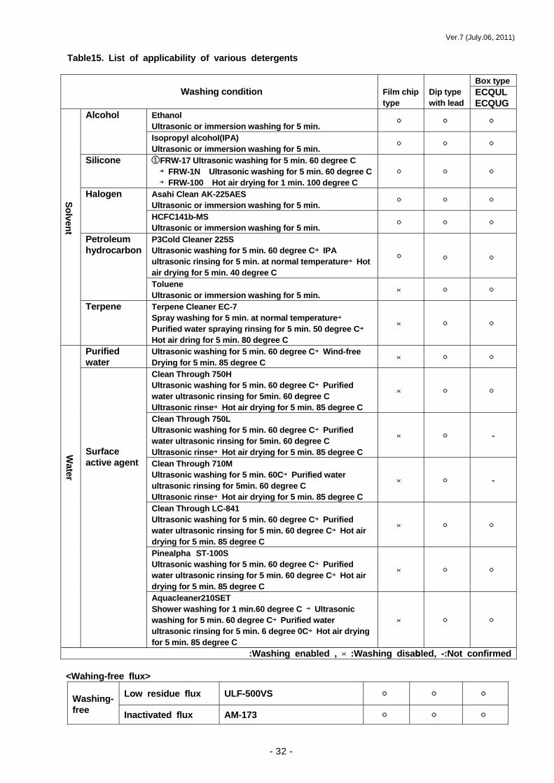
For using detergent after mounting, notice the effects before use because some solvent may cause deterioration of characteristics of capacitors or disappearance of indication. Refer to Table15 showing the effects caused by detergent generally used.
9.5 Resin coating
When capacitors are coated or embedded with resin for the purpose of moisture proof or fixing, solvent resistivity and temperature rise in curing may be brought as problems. In particular, contact us if resin is cured which causes heat of chemical reaction and higher temperature than specified one.
Careful considerations before use shall be needed that temperature changes in curing and actual use may cause lead wire to be cut due to concentration of stress on lead wire.
Ver.7 (July.06, 2011)
- 32 -
Table15. List of applicability of various detergents
Box type Washing condition
Film chip type
Dip type with lead
ECQUL ECQUG
Ethanol Ultrasonic or immersion washing for 5 min. ○ ○ ○ Alcohol
Isopropyl alcohol(IPA) Ultrasonic or immersion washing for 5 min. ○ ○ ○
Silicone ①FRW-17 Ultrasonic washing for 5 min. 60 degree C →FRW-1N Ultrasonic washing for 5 min. 60 degree C→FRW-100 Hot air drying for 1 min. 100 degree C
○ ○ ○
Asahi Clean AK-225AES Ultrasonic or immersion washing for 5 min. ○ ○ ○ Halogen
HCFC141b-MS Ultrasonic or immersion washing for 5 min. ○ ○ ○
P3Cold Cleaner 225S Ultrasonic washing for 5 min. 60 degree C→IPA ultrasonic rinsing for 5 min. at normal temperature→Hot air drying for 5 min. 40 degree C
○ ○ ○
Petroleum hydrocarbon
Toluene Ultrasonic or immersion washing for 5 min. × ○ ○
Terpene Terpene Cleaner EC-7 Spray washing for 5 min. at normal temperature→
Purified water spraying rinsing for 5 min. 50 degree C→
Hot air dring for 5 min. 80 degree C
× ○ ○
Purified water
Ultrasonic washing for 5 min. 60 degree C→Wind-free Drying for 5 min. 85 degree C × ○ ○
Clean Through 750H Ultrasonic washing for 5 min. 60 degree C→Purified water ultrasonic rinsing for 5min. 60 degree C Ultrasonic rinse→Hot air drying for 5 min. 85 degree C
× ○ ○
Clean Through 750L Ultrasonic washing for 5 min. 60 degree C→Purified water ultrasonic rinsing for 5min. 60 degree C Ultrasonic rinse→Hot air drying for 5 min. 85 degree C
× ○ -
Clean Through 710M Ultrasonic washing for 5 min. 60C→Purified water ultrasonic rinsing for 5min. 60 degree C Ultrasonic rinse→Hot air drying for 5 min. 85 degree C
× ○ -
Clean Through LC-841 Ultrasonic washing for 5 min. 60 degree C→Purified water ultrasonic rinsing for 5 min. 60 degree C→Hot air drying for 5 min. 85 degree C
× ○ ○
Pinealpha ST-100S Ultrasonic washing for 5 min. 60 degree C→Purified water ultrasonic rinsing for 5 min. 60 degree C→Hot air drying for 5 min. 85 degree C
× ○ ○
Surface active agent
Aquacleaner210SET Shower washing for 1 min.60 degree C →Ultrasonic washing for 5 min. 60 degree C→Purified water ultrasonic rinsing for 5 min. 6 degree 0C→Hot air drying for 5 min. 85 degree C
× ○ ○
○:Washing enabled , ×:Washing disabled, -:Not confirmed
<Wahing-free flux>
Low residue flux ULF-500VS ○ ○ ○ Washing-free Inactivated flux AM-173 ○ ○ ○
Solvent W
ater

Ver.7 (July.06, 2011)
- 33 -
10. Storage and prevention
(1) Keep the products at below temperature of 35 degree C and humidity of 85%. Storage period limit shall be 6 months from the delivery because corrosion on surfaces of lead wire caused by long term storage may bring deterioration of solderability. For the products which are stored over 6months, check the solderability and capacitance before use.
(2) Keep the products away from high temperature and humidity, dust, and corrosion/oxidized gas(hydrogen chloride, sulfur dioxide, hydrogen sulfide) etc. which may bring deterioration of electric characteristics and solderability of lead wire.
(3) It should be noted that moisture absorption may cause capacitance to change according to storage conditions
11. Others
・Measurement for RoHS directive As reduction of use of environmental burdens is required these days from the point of environmental conservation, our firm has worked on RoHS directive of Europe and the certain hazardous substances control law for electronic information products in China. Our film capacitors are suitable for RoHS directive(EU directive) of Europe . are placed on reels or C3 labels on packing boxes to show they are suitable
Contact us about information to be disclosed when exporting our products or incorporated products to China due to the certain hazardous substances control law for electronic information products in China. As a rule, formation shall be disclosed in delivery specifications. ・Detailed product specifications, product drawings and data for reliability can be available in our web site from
the address below. URL: http://industrial.panasonic.com/jp/i/21088/radial-lead-type/radial-lead-type.html
Plastic Film Capacitor Technical Guide
Date of issue First Edition Dec. 20, 1994 Second Edition Sep. 20, 1999 Third Edition Oct. 1, 2004 Fourth Edition Mar. 15, 2007 Fifth Edition Nov. 25, 2008 Sixth Edition Apr. 1, 2011 Seventh Edition Jul. 6, 2011
Issued by Engineering 1 Group, Film Capacitor Division. Panasonic Electronic Devices Japan Co., Ltd. Tel. 0852-32-2252 (direct phone)
This guide, or part of thereof, may not be reproduced in any form without permission of publishers.
G

Ver.7 (July.06, 2011)
- 34 -