Plasmonic Enhanced EIT and Velocity Selective Optical ...ulevy/paper119.pdf · ACS Photonics XXXX,...
8
Plasmonic Enhanced EIT and Velocity Selective Optical Pumping Measurements with Atomic Vapor Eliran Talker, † Pankaj Arora, † Yefim Barash, Liron Stern, and Uriel Levy* Department of Applied Physics, The Benin School of Engineering and Computer Science, The Center for Nanoscience and Nanotechnology, The Hebrew University of Jerusalem, Jerusalem, 91904, Israel * S Supporting Information ABSTRACT: In this work, we experimentally observe for the first time nanoscale plasmonic enhanced Electromagnetically Induced Transparency (EIT) and Velocity Selective Optical Pumping (VSOP) effects in miniaturized Integrated Quantum Plasmonic Device (IQPD) for D 2 transitions in rubidium (Rb). Our device consists of a vapor cell integrated on top of a prism coated with a thin layer of metal. This configuration is known to allow efficient excitation of Surface Plasmon Resonance (SPR). The evanescent field of the surface plasmon mode interacts with the atomic media in close vicinity to the metal. In spite of the limited interaction length between SPR and Rb atoms, the signature of EIT along with VSOP signals could be clearly observed in our miniaturized IQPD under proper conditions of pump and probe intensities. A gradual decrease in the contrast of the plasmonic enhanced EIT and VSOP signals was observed as the excitation was detuned from the SPR critical angle, due to reduction in electromagnetic field enhancement, leading to a reduced interaction of the evanescent field with the atomic vapor media. Following the demonstration of these effects, we also present a detailed model revealing the mechanisms and the origin of plasmonic enhanced EIT and VSOP effects in our system. The model, which is based on the Bloch equations, is in good agreement with the observed experimental results. The obtained results are regarded as an important step in the quest for the realization of nanoscale quantum plasmonic effects and devices. KEYWORDS: surface plasmons, plasmon-atom interaction, quantum plasmonics, spectroscopy, atom optics T he quantum interference due to coherent coupling between narrow and broad resonances leads to a sharp resonance of nearly perfect transmission known as Electro- magnetically Induced Transparency (EIT). The EIT phenom- enon is attracting growing attention due to its scientific merits as well as the potential applications, for example, in nonlinear optics, lasing without inversion, storage of light, ultraslow propagation, quantum memory, and quantum sensing, to name a few. 1−6 Motivated by the strong field localization and field enhancement, plasmonic and metamaterial nanostructures has been exploited to demonstrate EIT effects with high figure of merit in terms of narrow transparency and high modulation depth. 7−10 Traditionally, in the area of atomic physics, the principle of EIT is that an atomic coherence is induced in a multilevel system by a strong “pump” laser field which alters the response of the system to a “probe” laser field. The utmost simple level scheme for studying EIT features is that of the three level system 11 which can be classified into three categories: V-type, Lambda-type (Λ), and Cascade-type (Ξ). Yet, the study of EIT is not restricted to three level systems as evident, for example, by the plethora of EIT demonstrations in four-level 12−14 and even five level 15,16 systems. Observing EIT in V-type system is impossible for a cold V-type system because the quantum interference in such system is constructive. However, if the Doppler effect (for warm atomic or molecular gases) is taken into account, an EIT is possible and a crossover from EIT to Autler-Townes splitting can be observed. 17−20 For a typical V-type three level atomic system, the medium becomes transparent only at the centerline of the probe transition and no extra peaks are generated. However, in the case of multilevel (more than three levels) systems, due to the presence of extra upper levels with spacing smaller than the Doppler broadened transition, extra peaks, known as Velocity Selective Optical Pumping (VSOP) peaks, are also observed along with the EIT peak. 21−24 We will discuss these effects further in the text. We have chosen to focus on the V-type system rather than on the Lambda-type (Λ) or the Cascade- type (Ξ) systems because it is more difficult to observe the discussed effects in the V- type configuration. As such, it is the ideal system to make the case for plasmonics as it significantly enhancing VSOP and EIT effects, which may be difficult to observe in other, nonplasmonic miniaturized systems, such as total internal reflection glass prism with no metal coating. In parallel, atomic spectroscopy in confined miniaturized cells 25−29 is a promptly emerging field with implications Special Issue: Recent Developments and Applications of Plasmonics Received: October 30, 2017 Published: January 25, 2018 Article Cite This: ACS Photonics XXXX, XXX, XXX-XXX © XXXX American Chemical Society A DOI: 10.1021/acsphotonics.7b01284 ACS Photonics XXXX, XXX, XXX−XXX
Transcript of Plasmonic Enhanced EIT and Velocity Selective Optical ...ulevy/paper119.pdf · ACS Photonics XXXX,...

Plasmonic Enhanced EIT and Velocity Selective Optical PumpingMeasurements with Atomic VaporEliran Talker,† Pankaj Arora,† Yefim Barash, Liron Stern, and Uriel Levy*
Department of Applied Physics, The Benin School of Engineering and Computer Science, The Center for Nanoscience andNanotechnology, The Hebrew University of Jerusalem, Jerusalem, 91904, Israel
*S Supporting Information
ABSTRACT: In this work, we experimentally observe for thefirst time nanoscale plasmonic enhanced ElectromagneticallyInduced Transparency (EIT) and Velocity Selective OpticalPumping (VSOP) effects in miniaturized Integrated QuantumPlasmonic Device (IQPD) for D2 transitions in rubidium(Rb). Our device consists of a vapor cell integrated on top of aprism coated with a thin layer of metal. This configuration isknown to allow efficient excitation of Surface PlasmonResonance (SPR). The evanescent field of the surface plasmonmode interacts with the atomic media in close vicinity to themetal. In spite of the limited interaction length between SPR and Rb atoms, the signature of EIT along with VSOP signals couldbe clearly observed in our miniaturized IQPD under proper conditions of pump and probe intensities. A gradual decrease in thecontrast of the plasmonic enhanced EIT and VSOP signals was observed as the excitation was detuned from the SPR criticalangle, due to reduction in electromagnetic field enhancement, leading to a reduced interaction of the evanescent field with theatomic vapor media. Following the demonstration of these effects, we also present a detailed model revealing the mechanismsand the origin of plasmonic enhanced EIT and VSOP effects in our system. The model, which is based on the Bloch equations, isin good agreement with the observed experimental results. The obtained results are regarded as an important step in the quest forthe realization of nanoscale quantum plasmonic effects and devices.
KEYWORDS: surface plasmons, plasmon-atom interaction, quantum plasmonics, spectroscopy, atom optics
The quantum interference due to coherent couplingbetween narrow and broad resonances leads to a sharp
resonance of nearly perfect transmission known as Electro-magnetically Induced Transparency (EIT). The EIT phenom-enon is attracting growing attention due to its scientific meritsas well as the potential applications, for example, in nonlinearoptics, lasing without inversion, storage of light, ultraslowpropagation, quantum memory, and quantum sensing, to namea few.1−6 Motivated by the strong field localization and fieldenhancement, plasmonic and metamaterial nanostructures hasbeen exploited to demonstrate EIT effects with high figure ofmerit in terms of narrow transparency and high modulationdepth.7−10 Traditionally, in the area of atomic physics, theprinciple of EIT is that an atomic coherence is induced in amultilevel system by a strong “pump” laser field which alters theresponse of the system to a “probe” laser field. The utmostsimple level scheme for studying EIT features is that of thethree level system11 which can be classified into threecategories: V-type, Lambda-type (Λ), and Cascade-type (Ξ).Yet, the study of EIT is not restricted to three level systems asevident, for example, by the plethora of EIT demonstrations infour-level12−14 and even five level15,16 systems. Observing EITin V-type system is impossible for a cold V-type system becausethe quantum interference in such system is constructive.However, if the Doppler effect (for warm atomic or molecular
gases) is taken into account, an EIT is possible and a crossoverfrom EIT to Autler-Townes splitting can be observed.17−20 Fora typical V-type three level atomic system, the mediumbecomes transparent only at the centerline of the probetransition and no extra peaks are generated. However, in thecase of multilevel (more than three levels) systems, due to thepresence of extra upper levels with spacing smaller than theDoppler broadened transition, extra peaks, known as VelocitySelective Optical Pumping (VSOP) peaks, are also observedalong with the EIT peak.21−24 We will discuss these effectsfurther in the text. We have chosen to focus on the V-typesystem rather than on the Lambda-type (Λ) or the Cascade-type (Ξ) systems because it is more difficult to observe thediscussed effects in the V- type configuration. As such, it is theideal system to make the case for plasmonics as it significantlyenhancing VSOP and EIT effects, which may be difficult toobserve in other, nonplasmonic miniaturized systems, such astotal internal reflection glass prism with no metal coating.In parallel, atomic spectroscopy in confined miniaturized
cells25−29 is a promptly emerging field with implications
Special Issue: Recent Developments and Applications of Plasmonics
Received: October 30, 2017Published: January 25, 2018
Article
Cite This: ACS Photonics XXXX, XXX, XXX−XXX
© XXXX American Chemical Society A DOI: 10.1021/acsphotonics.7b01284ACS Photonics XXXX, XXX, XXX−XXX

ranging from precision analysis of atomic structures toapplications such as magnetometry,30 optical and radiofrequency standards,31 and optical isolation.32 Recent effortsare tailored toward the on-chip integration of atomic andnanophotonic systems, primarily motivated by the capability toenhance light−matter interactions at the nanometer scale.33−37
In this work, we report on an Integrated Quantum PlasmonicDevice (IQPD) supporting the interactions of plasmons withatomic vapor at the nanoscale. This device is utilized toexperimentally demonstrate plasmonic enhanced EIT andVSOP effects. Specifically, Surface Plasmon Resonance (SPR)is excited by a prism coated by a thin metallic film. While suchsystem in which the excited Surface Plasmons (SPs) areinteracting with atomic vapor of rubidium (Rb) via theevanescent tail of the plasmonic mode has been demonstratedbefore, primarily for the purpose of controlling dispersion,demonstrating Fano line shape and all-optical switching,33 herewe take advantage of such interactions and the significant fieldenhancement in order to demonstrate theoretically andexperimentally for the first time EIT and VSOP effects inminiaturized vapor cells. The reported result can be regarded asan additional step in the quest for the realization of quantumplasmonic effects and devices.38,39
■ FABRICATION
The device was constructed on top of a right-angle CaF2 prism.After cleaning with soap water and DI water, a stack of 3 nmchromium (as an adhesion layer), a 35 nm layer of gold and a 5nm-thick layer of MgF2 were evaporated on top of the prism atdeposition rates of 0.3, 0.5, and 0.3 Å/s, respectively. The 5 nmthick MgF2 layer on top of gold serves as a capping layer, toprevent chemical interaction between the gold and the Rbatoms. After evaporation, a Pyrex cell was bonded to the prismusing thermally cured epoxy and baked out at a temperature of70 °C for 3 h. The integrated device was baked out for 48 husing a turbo vacuum system which is connected to the celluntil a vacuum level in the range of 10−7−10−8 Torr wasreached. Finally, a droplet of natural Rb was inserted into thecell which was prepared by condensation of Rb vapors invacuum system connected to aluminosilicate glass ampulecontaining rubidium chloride (RbCl) and calcium (Ca), placedin high temperature oven. The Rb vapors were obtained byreduction of the RbCl with Ca.40 The reduction reaction tookplace at elevated temperature, producing gaseous Rb whichcondensates on the cool walls of the glass system’s main tube.Then it was transferred to the sample cell attached to the maintube, after which the cell was disconnected from the vacuumsystem and sealed. Figure 1a,b show the schematic and actualphotograph of miniaturized IQPD filled with Rb atoms,respectively.
■ NUMERICAL PLASMONIC SIMULATIONS
The reflection and the electromagnetic field distribution in thebare plasmonic structure, prior to the introduction of Rb, werecalculated using the transfer matrix method and ComsolMultiphysics, respectively. Here, the structure is represented bya glass prism with a refractive index of 1.4307, followed bymetallic chromium and gold layers (refractive index of 3.9592 −i4.1936 and 0.18210 − i4.8493, respectively), and an MgF2capping layer with refractive index of 1.3753. This structurewith air on top was used to calculate reflectivity curve of the SPmode as a function of the incident angle. Essentially, we assume
the attenuated total internal reflection based Kretschmannconfiguration,41 where the evanescent field from a TransverseMagnetic (TM) polarized light is coupled to SP mode aroundthe critical resonance angle.
■ NUMERICAL RESULTThe simulated reflectivity of light at 780 nm through theplasmonic prism (not considering the effect of the Rb vapor) asa function of incident angle was calculated using the above-mentioned transfer matrix method. The result is shown inFigure 1c, solid blue line. The dip in reflection, which isattributed to the coupling of light to the SP mode, is obtainedat an angle of 46.2°, which is defined as 0°. To compare thesimulation with experiment data, a TM polarized light derivedfrom 780 nm wavelength laser source (TOPTICA, DL pro)was used to excite IQPD, which was mounted on a rotationstage. The reflected signal was measured using a photodetector,
Figure 1. (a) Schematic and (b) photograph of miniaturized IQPDfilled of Rb atoms. (c) Simulated and measured SP reflectivity curvefor plasmonic prism as a function of incident angle.
ACS Photonics Article
DOI: 10.1021/acsphotonics.7b01284ACS Photonics XXXX, XXX, XXX−XXX
B

while controlling the angle of the rotation stage over a widerange of angles spanning approximately ±3° around theplasmonic resonance with the angular resolution of 0.05°.The measured results are shown in Figure 1c, red dashed line.The reflectivity curves obtained from simulation and measure-ment were found in a good agreement.
■ MODELING THE INTEGRATED QUANTUMPLASMONIC DEVICE
Two major configurations can be applied to study light-atominteraction as shown in Figure 2a. One is the direct interaction
of the incident light represented as |i⟩ state with the atomicmedia represented as |a⟩ state. Alternatively, the incident lightstate |i⟩ is first coupled to a plasmonic state |p⟩ and then theplasmonic state |p⟩ couples to atomic state |a⟩.33,42 In this work,we are focused on the second case, i.e. plasmonic enhancedlight-atom interaction (see Supporting Information, pages S1−S3) using our proposed IQPD device.Next, we introduce the atomic media in details. The energy
levels relevant for the observation of VSOP and EIT in oursetup are shown in Figure 2b. We consider a six-level hyperfinestructure of 85Rb D2 transition, where the energy levels aredenoted as i = 1−6 and the spacing between the hyperfinesplitting of the excited state is δ1 = 29 MHz, δ2 = 63 MHz, andδ3 = 120 MHz, respectively.43 In the considered V-typeconfiguration, Level |2⟩ is coupled to level |5⟩ by the strongpump laser beam, and to levels |4⟩, |5⟩, and |6⟩ by the weakprobe laser beam. In a Doppler broadened system, thefrequency detuning from the resonance of the pump andprobe fields are defined as
Δ = ·
Δ = · − Δ
k v
k v
p pu
c pr (1)
where v is the atomic velocity, Δis the detuning from resonanceand kpu and kpr are the pump and probe wave-vectors,respectively. It should be noted that for zero detuning, thereis still a residual Doppler line width ΔvD, which can be writtenfor a V-type system as
Δ = |⎯→⎯
−⎯→
|·⎯→v k k vD pu pr p (2)
where ⎯→vp is the most probable velocity of the atoms. This isequivalent to the case of nearly Doppler free environment dueto using same wavelength in a nearly collinear configuration.44
To better understand the physical ground of this work, wehave first calculated the optical susceptibility for a six-levelquantum system of Rb atoms, where plasmonic effects are notpresent. Our theoretical calculations are based on a standarddensity matrix approach. The dynamical behavior of the densitymatrix ρ can be given by the Liouville equation of motion
ρ ρ ρ= −ℏ
+ Γt
idd
[ , ](3)
where Γ is the relaxation matrix, is the Hamiltonian of thesix-level atomic system including the electric dipole interactionand rotating wave approximation, which can be written as
∑ ∑
= + +
= − | ⟩⟨ | − ℏ Ω | ⟩⟨ | + Ω | ⟩⟨ |= =
⎡⎣⎢⎢
⎤⎦⎥⎥
V V
E j j z j z2
( ) 2 ( ) 2 5j
jj
j
0 1 2
1
6
4
6
pr2
pu25
(4)
Figure 2. (a) Coupling mechanism in plasmonic-atomic hybridsystem. |i> represents the incident light state, couples to the plasmonicstate |p>. Then the plasmonic state |p> couples to discrete atomic state|a>. This is in contrast to the conventional light vapor interactionsexperiments, where direct light-atom coupling takes place by allowingthe incident light state |i> to directly couple to an atomic state |a>. (b)Level scheme for 85Rb-D2 transition in V-type configuration.
Figure 3. (a) Simulated normalized steady-state susceptibility of thesix level atomic system. Temperature of 60 °C was assumed. The Rabifrequency for the pump and probe lasers were Ωpu = 5γ and Ωpr = 2γ,respectively. The VSOP peaks can be clearly observed. (b) Zoom in onthe 3rd VSOP peak, where the super imposed EIT peak can beobserved.
ACS Photonics Article
DOI: 10.1021/acsphotonics.7b01284ACS Photonics XXXX, XXX, XXX−XXX
C
where E is the energy value of each level and Ωpu,pr are the Rabifrequencies for the pump and probe beam, respectively, whichcan be written as
Ω = −·⎯ →⎯⎯⎯⎯⎯⎯
ℏd E
pu,pr0,pu,pr
(5)
Here d represents the dipole matrix and⎯ →⎯⎯⎯⎯⎯⎯
E0,pu,pr represents
the electric field for pump and probe, respectively. All thespontaneous emission rates of the excited states were presumedto be the same and all the ground level population relaxationrates were ignored under the assumption that the ground statesare stable. We have assumed that the atomic density issufficiently low to neglect the atom−atom interactions(collisional broadening). The bandwidth of the lasers wasincorporated into the calculations by introducing relaxationterms for the nondiagonal density matrix elements using theprocedure developed in ref 45.As a result of applying this model, the imaginary part of the
optical susceptibility χI(Δ) related to the density matrix isplotted for the six-level atomic system, using following equation
∑χ ρΔ = −ϵ ℏΩ
Δ=
Im d( )2
( )i iI0 pr i 4
6
2,2
2,(6)
where is the uniform number density for an atomicensemble. The results are shown in Figure 3. The presence offive peaks corresponding to VSOP signal (solid red line) can beclearly observed in Figure 3a. These five peaks are labeled in thefigure. The simulation represents a realistic experimentalscenario, in which we measure the superimposed intensity ofthe pump and the probe beam. Basically, one should observe sixpeaks. Three are originated from changing the populationdistribution of the ground states due to velocity selectiveprocess. (The pump beam is set to F = 3 → F′ = 3 transition.)The Doppler shift causes the pump beam to interact with threegroups of atoms: first group with velocity zero or perpendicularto the pump beam; therefore these atoms will be absorbed atfrequency equals to F = 3→ F′ = 3 transition. Second and thirdgroups of atoms should have a velocity that cause Doppler shift,fit for the transition F = 3→ F′ = 2, 4; the other three peaks aregenerated by the probe beam according to changing thepopulation in the ground states by scanning the probe beam.46
Yet, two of the peaks occur at the same frequency, and thusonly five peaks are observed. Figure 3b shows a zoom in on thecentral peak labeled as third VSOP peak, and shaded by cyanrectangle in Figure 3a. Now, it is possible to observe anadditional narrow peak (line width 8 MHz) on top of the thirdVSOP peak, which is attributed to the EIT effect. It should benoted that an EIT peak could be clearly observed in V-typeconfiguration only if Ωpr < Ωpu and Ωpu ≫ γ (see Supporting
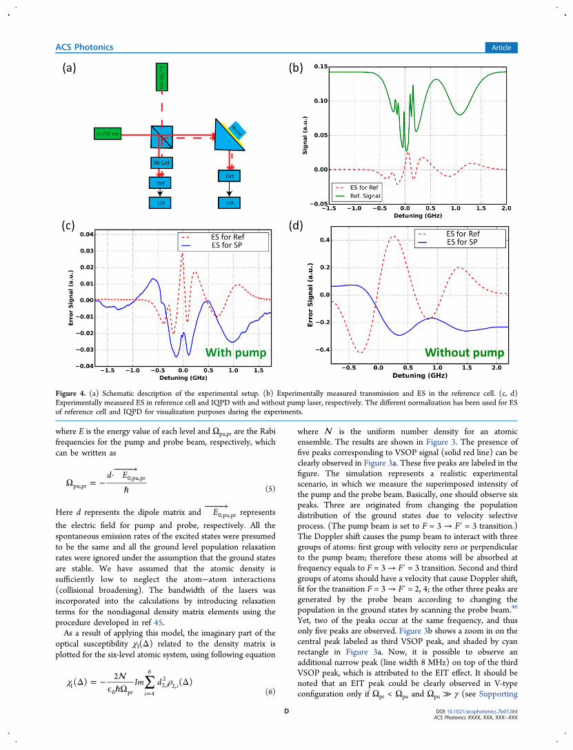
Figure 4. (a) Schematic description of the experimental setup. (b) Experimentally measured transmission and ES in the reference cell. (c, d)Experimentally measured ES in reference cell and IQPD with and without pump laser, respectively. The different normalization has been used for ESof reference cell and IQPD for visualization purposes during the experiments.
ACS Photonics Article
DOI: 10.1021/acsphotonics.7b01284ACS Photonics XXXX, XXX, XXX−XXX
D

Information, pages S4−S6). In the simulation, we assumed Ωpu= 5γ, Ωpr = 2γ, whereas γ is the natural line width.
■ EXPERIMENTAL OBSERVATIONS IN THEINTEGRATED QUANTUM PLASMONIC DEVICE
After observing the signature of EIT and VSOP peaks insimulations, we turn into their experimental observation. Figure
4a shows the experimental set up used for observing theseeffects. Briefly, a high power, 780 nm (TOPTICA, DL pro)
wavelength laser source (acts as a pump) and a lower power,780 nm (New Focus, TLB-6700) wavelength laser source (actsas a probe) were combined (TM polarization), collimated, andcopropagated toward the IQPD. The reflected signal wasmeasured using a photodetector. After which, it wasdemodulated and amplified using lock-in amplifier (LIA, SRSmodel SR830), while scanning, at low frequency, the opticalfrequency of the laser across the absorption line. During themeasurement, we only demodulated the weak probe beam,whereas the stronger pump beam remained constant withoutany frequency modulation. The LIA provides an Error Signal(ES), which is proportional to the derivative of the signal.In parallel, a beam splitter was also placed in the path of the
copropagating light for the purpose of tapping some of the lightand performing a parallel measurement using a 7.5 cm longreference vapor cell filled with natural Rb. The integrateddevice was heated using homemade resistive heaters and atemperature gradient was maintained during the experiment toavoid the adsorption of Rb atoms on the gold layer. Theintensity of the incident light was controlled by Neutral Densityfilters.The measured transmission curve for the 7.5 cm long
reference cell is shown in Figure 4b (solid green line). Thepresence of the five peaks is clearly observed in agreement withthe simulation results. We have also measured the ES which isproportional to the derivative of the signal with the help of theLIA, where the signature of VSOP peaks can also be seen(dashed red line). This ES is used as a reference for the purposeof comparison to the ES measured in the IQPD, as shown inthe next paragraph.After demonstrating the VSOP effects in the reference cell,
we now focus on the study and the demonstration of theseeffects in our IQPD. Here, the interaction length ofelectromagnetic field with the atomic media is now significantlyshorter as compared to the reference cell, resulting in a lowercontrast, which can only be observed by extracting the ES. TheES of the reflection spectrum measured in our IQPD is shownin Figure 4c, blue line, with pump power of 137 μW and probepower of 42.5 μW, respectively. The VSOP effects can beclearly observed. One may observe that the ES of the IQPD ismostly negative, indicating VSOP dips rather than peaks, as waspredicted and observed before.28,40 To verify the presence ofVSOP signal, we have blocked the pump laser such that thesample was excited only by the probe laser in both thereference cell and the IQPD. Figure 4d shows the ES for thereference cell and the IQPD without the presence of the pumplaser. The absence of VSOP signal serves as a controlexperiment and supports the claim that the signal shown inFigure 4c is indeed originating from the VSOP effect.After observing the VSOP signature in the IQPD, we have
repeated the measurements, this time while controlling theangle of incidence as shown in Figure 5. As can be seen, bydetuning away from the angle of plasmonic resonance, a gradualdecrease in the contrast of VSOP signal is observed. This isbecause when the angle of incidence is detuned fromresonance, the electromagnetic field enhancement at themetal-vapor interface is gradually decreased, and correspond-ingly the interaction between SP mode and atomic vapors isreduced as well. By comparing Figure 5a to Figure 5b, one mayobserve that the decrease in the contrast of VSOP signal is notsymmetric. This is due to the asymmetric nature of the excitedSP mode (see Figure 1c).
Figure 5. Experimentally measured ES for VSOP effect as a function ofincident angles in IQPD: (a) In negative (left side from the resonanceangle) direction; (b) In positive (right side from the resonance angle)direction.
Figure 6. Experimental measured EIT signal in reference cell andIQPD.
ACS Photonics Article
DOI: 10.1021/acsphotonics.7b01284ACS Photonics XXXX, XXX, XXX−XXX
E

Next, we have focused on the experimental observation ofEIT feature in the reference cell and IQPD, as shown in Figure6. This time, we measured over a limited spectral band of about160 MHz with increased pump power of 224 μw in order toimprove the signal contrast. By zooming in on the third VSOPpeak region and choosing pump power of 224 μW and probepower of 26 μW, respectively, we could now observe an EITsignal in the reference Rb cell (dashed red line), which appearsas a sharp peak on top of third broader VSOP peak (Figure 6).The observed EIT signal was noticed to be a bit asymmetricand not perfectly centered as compared to simulation result(Figure 3b). This is probably due to a small detuning of thepump beam during the experiment. The green and blue linesare the ES of the reference cell and IQPD respectively, wherethe signature of EIT signal is clearly observed in both cases. Ascan be seen, the change in the ES around the EIT spectralregime (corresponding to a variation in the derivative of thesignal) is limited to a narrow frequency regime as compared tothe ES of the VSOP. Thus, it is evident that the line width forEIT signal is significantly narrower than the line width of VSOPsignal in both the reference cell and the IQPD, in agreementwith previously demonstrated results.23,24 Comparing the linewidth of the EIT feature observed in the IQPD system to the
reference signal, the feature was found to be broader in ourIQPD system. This is attributed to transit time broadening inour plasmonic system.After observing the EIT signal in the IQPD, the power for
the probe laser was gradually increased to see its effect on theEIT signal. The pump power was kept constant (224 μw).As the probe power was increased from 47 μw to 181 μw, as
shown in Figure 7a and b, respectively, the decrease in thecontrast of EIT signal was noticed in both reference cell and theIQPD. When the probe power was further increased toward thepower level of the pump beam (Figure 7c,d), the signature ofEIT signal could not be observed. This is due to the fact thatthe required pump−probe condition for observation of EIT isno longer fulfilled, as was previously discussed in Figure 3b.Finally, to demonstrate the role of plasmons in enhancing the
EIT signal in our IQPD, we have measured the ES while tuningthe angle of incidence, using pump power of 224 μW and probepower of 26 μW, respectively, during the experiment. Theobtained results are shown in Figure 8. As in the case of VSOP,one can clearly observe that as the angle of incidence is furtherdetuned from the plasmonic resonance, a gradual decrease inthe contrast of the EIT signal is observed. Again, this can beexplained by the gradual decrease in field enhancement, as
Figure 7. EIT spectrum in the reference cell and in our IQPD for various probe powers (a) 47, (b) 181, (c) 218, and (d) 238 μw, respectively. Forcomparison purposes, error signal (ES) has been used for both the reference cell and the IQPD in all four panels.
ACS Photonics Article
DOI: 10.1021/acsphotonics.7b01284ACS Photonics XXXX, XXX, XXX−XXX
F

discussed in Figure S2 of the Supporting Information. In fact,the utilization of plasmonic effects is beneficial not only fromminiaturization and field enhancement perspective, but alsofrom the perspective of lifetime shortening, which assists indiminishing other mechanisms such as optical pumping whichmay compete with the EIT effect.
■ CONCLUSIONSIn this work, we have observed plasmonic enhanced VelocitySelective Optical Pumping (VSOP) and ElectromagneticInduced Transparency (EIT) signals in a miniaturizedIntegrated Quantum Plasmonic Device (IQPD). The deviceis realized by the integration of metal coated prism with atomicvapor media. The results were obtained under differentconditions of pump and probe intensities, and under differentdetuning conditions from the critical angle for surface plasmonresonance (SPR). We observed a gradual increase in thecontrast of nanoscale plasmonic enhanced VSOP and EITsignals as the angle of incidence approaches the critical SPRangle. This is attributed to the plasmonic field enhancement inthe vicinity of the metal−vapor interface. We have alsoobserved an increase in EIT contrast by increasing the intensityratio between the pump and the probe. To support ourexperimental observations, we have calculated the expectedsignal in our system using numerical simulations based on theoptical Bloch equation. The calculated effect was found to be ingood agreement with the observed experimental results. OurIQPD and its functionality can be regarded as an additionalstep in the quest for the realization of nanoscale quantumplasmonic effects and devices. While ohmic loss results in thebroadening of the plasmonic resonance, the effect of field
enhancement provides valuable features compensating for suchbroadening. In future work, we intend to replace the metal filmwith plasmonic nanostructures such as nanoantennas. Whileohmic loss will still play a role, we will benefit from even moreextreme light confinement and field enhancement which isexpected to make the plasmonic-atomic EIT more attractive forpractical applications.
■ ASSOCIATED CONTENT*S Supporting InformationThe Supporting Information is available free of charge on theACS Publications website at DOI: 10.1021/acsphoto-nics.7b01284.
Plasmonic enhancement in EIT and VSOP features; Vtype configuration for observing EIT features (PDF).
■ AUTHOR INFORMATIONCorresponding Author*E-mail: [email protected] Arora: 0000-0002-0451-9518Uriel Levy: 0000-0002-5918-1876Author Contributions†E.T. and P.A. contributed equally to this work.NotesThe authors declare no competing financial interest.
■ ACKNOWLEDGMENTSWe acknowledge financial support from the ERC ProjectLight−Vapor Interactions on a chip (LIVIN).
■ REFERENCES(1) Harris, S. E.; Field, J. E.; Imamoglu, A. Nonlinear OpticalProcesses Using Electromagnetically Induced Transparency. Phys. Rev.Lett. 1990, 64, 1107−1110.(2) Abel, R. P.; Mohapatra, A. K.; Bason, M. G.; Pritchard, J. D.;Weatherill, K. J.; Raitzsch, U. Laser Frequency Stabilization to ExcitedState Transitions Using Electromagnetically Induced Transparency ina Cascade System. Appl. Phys. Lett. 2009, 94, 071107.(3) Phillips, D. F.; Fleischhauer, A.; Mair, A.; Walsworth, R. L.Storage of Light in Atomic Vapor. Phys. Rev. Lett. 2001, 86, 783−786.(4) Shuker, M.; Firstenberg, O.; Pugatch, R.; Ron, A.; Davidson, N.Storing Images in Warm Atomic Vapor. Phys. Rev. Lett. 2008, 100,223601.(5) Harris, S. E. Lasers without Inversion: Interference of Lifetime-Broadened Resonances. Phys. Rev. Lett. 1989, 62, 1033−1036.(6) Liu, C.; Dutton, Z.; Behroozi, C. H.; Hau, L. V. Observation ofCoherent Optical Information Storage in an Atomic Medium UsingHalted Light Pulses. Nature 2001, 409, 490−493.(7) Zhang, S.; Genov, D. A.; Wang, Y.; Liu, M.; Zhang, X. Plasmon-Induced Transparency in Metamaterials. Phys. Rev. Lett. 2008, 101,47401.(8) Dong, Z.; Liu, H.; Cao, J.; Li, T.; Wang, S.; Zhu, S.; Zhang, X.Enhanced Sensing Performance by the Plasmonic Analog ofElectromagnetically Induced Transparency in Active Metamaterials.Appl. Phys. Lett. 2010, 97, 114101.(9) Liu, N.; Langguth, L.; Weiss, T.; Kastel, J.; Fleischhauer, M.; Pfau,T.; Giessen, H. Plasmonic Analogue of Electromagnetically InducedTransparency at the Drude Damping Limit. Nat. Mater. 2009, 8, 758−762.(10) Wu, D.; Liu, Y.; Yu, L.; Yu, Z.; Chen, L.; Li, R.; Ma, R.; Liu, C.Plasmonic Metamaterial for Electromagnetically Induced Trans-parency Analogue and Ultra- High Figure of Merit Sensor. Sci. Rep.2017, 7, 45210.
Figure 8. Experimental measured ES for EIT effect as a function ofincident angle in IQPD: (a) In negative (Left side from the resonanceangle) direction; (b) In positive (right side from the resonance angle)direction.
ACS Photonics Article
DOI: 10.1021/acsphotonics.7b01284ACS Photonics XXXX, XXX, XXX−XXX
G
(11) Li, Y.; Jin, S.; Xiao, M. Observation of an ElectromagneticallyInduced Change of Absorption in Multilevel Rubidium Atoms. Phys.Rev. A: At., Mol., Opt. Phys. 1995, 51, 1754−1757.(12) Agarwal, G. S.; Harshawardhan, W. Inhibition and Enhancementof Two Photon Absorption. Phys. Rev. Lett. 1996, 77, 1039−1042.(13) McGloin, D. Coherent Effects in a Driven Vee Scheme. J. Phys.B: At., Mol. Opt. Phys. 2003, 36, 2861−2871.(14) Lukin, M. D.; Imamoglu, A. Controlling Photons UsingElectromagnetically Induced Transparency. Nature 2001, 413, 273−276.(15) Ottaviani, C.; Rebic, S.; Vitali, D.; Tombesi, P. Quantum Phase-Gate Operation Based on Nonlinear Optics: Full Quantum Analysis.Phys. Rev. A: At., Mol., Opt. Phys. 2006, 73, 10301.(16) Wu, Y.; Saldana, J.; Zhu, Y. Large Enhancement of Four-WaveMixing by Suppression of Photon Absorption from Electromagneti-cally Induced Transparency. Phys. Rev. A: At., Mol., Opt. Phys. 2003, 67,13811.(17) Agarwal, G. S. Nature of the Quantum Interference inElectromagnetic-Field-Induced Control of Absorption. Phys. Rev. A:At., Mol., Opt. Phys. 1997, 55, 2467−2470.(18) Anisimov, P.; Kocharovskaya, O. Decaying-Dressed-StateAnalysis of a Coherently Driven Three-Level System. J. Mod. Opt.2008, 55, 3159−3171.(19) Abi-Salloum, T. Y. Electromagnetically Induced Transparencyand Autler-Townes Splitting: Two Similar but Distinct Phenomena inTwo Categories of Three-Level Atomic Systems. Phys. Rev. A: At., Mol.,Opt. Phys. 2010, 81.10.1103/PhysRevA.81.053836(20) Zhu, C.; Tan, C.; Huang, G. Crossover from Electromagneti-cally Induced Transparency to Autler-Townes Splitting in Open V-Type Molecular Systems. Phys. Rev. A: At., Mol., Opt. Phys. 2013, 87,1−13.(21) Bhattacharyya, D.; Ray, B.; Ghosh, P. N. Theoretical Study ofElectromagnetically Induced Transparency in a Five-Level Atom andApplication to Doppler-Broadened and Doppler-Free Rb Atoms. J.Phys. B: At., Mol. Opt. Phys. 2007, 40, 4061−4075.(22) Ying, K.; Niu, Y.; Chen, D.; Cai, H.; Qu, R. Observation ofMulti-Electromagnetically Induced Transparency in V-Type RubidiumAtoms. J. Mod. Opt. 2014, 61, 631−635.(23) Bhattacharyya, D.; Ghosh, A.; Bandyopadhyay, A.; Saha, S.;Sankar De. Comparison of Electromagnetically Induced Transparency(EIT) Spectra for Six-Level Lambda (Λ) and Five-Level V-TypeSystems. J. Atomic, Mol., Condens. Nano Phys. 2015, 2, 93−99.(24) Mitra, S.; Dey, S.; Hossain, M. M.; Ghosh, P. N.; Ray, B.Temperature and Magnetic Field Effects on the Coherent andSaturating Resonances in Λ- and V-Type Systems for the 85Rb-D2Transition. J. Phys. B: At., Mol. Opt. Phys. 2013, 46, 75002.(25) Schwindt, P. D. D.; Knappe, S.; Shah, V.; Hollberg, L.; Kitching,J.; Liew, L.; Moreland, J.; Schwindt, P. D. D.; Knappe, S.; Shah, V.;et al. Chip-Scale Atomic Magnetometer. Appl. Phys. Lett. 2004, 85,6409−6411.(26) Benabid, F.; Couny, F.; Knight, J. C.; Birks, T. A.; Russell, P. S. J.Compact, Stable and Efficient All-Fibre Gas Cells Using Hollow-CorePhotonic Crystal Fibres. Nature 2005, 434, 488.(27) Yang, W.; Conkey, D. B.; Wu, B. I. N.; Yin, D.; Hawkins, A. R.;Schmidt, H. Atomic Spectroscopy on a Chip. Nat. Photonics 2007, 1,331−335.(28) Baluktsian, T.; Urban, C.; Bublat, T.; Giessen, H.; Low, R.; Pfau,T. Fabrication Method for Microscopic Vapor Cells for Alkali Atoms.Opt. Lett. 2010, 35, 1950−1952.(29) Sargsyan, A.; Leroy, C.; Pashayan-Leroy, Y.; Mirzoyan, R.;Papoyan, A.; Sarkisyan, D. High Contrast D 1 Line Electromagneti-cally Induced Transparency in Nanometric-Thin Rubidium VaporCell. Appl. Phys. B: Lasers Opt. 2011, 105, 767−774.(30) Kominis, I. K.; Kornack, T. W.; Allred, J. C.; Romalis, M. V. ASubfemtotesla Multichannel Atomic Magnetometer. Nature 2003, 422,596−599.(31) Venkataraman, V.; Saha, K.; Londero, P.; Gaeta, A. L. Few-Photon All-Optical Modulation in a Photonic Band-Gap Fiber. Phys.Rev. Lett. 2011, 107, 193902.
(32) Salit, K.; Salit, M.; Krishnamurthy, S.; Wang, Y.; Kumar, P.;Shahriar, M. S. High Bandwidth, Ultra-Low Power All OpticalModulation with a Nano-Fiber Embedded in Rb Vapor. OSA CLEO2010, 1−2.(33) Stern, L.; Grajower, M.; Levy, U. Fano Resonances and All-Optical Switching in a Resonantly Coupled Plasmonic−atomicSystem. Nat. Commun. 2014, 5, 1−9.(34) Stern, L.; Zektzer, R.; Mazurski, N.; Levy, U. Enhanced Light-Vapor Interactions and All Optical Switching in a Chip Scale Micro-Ring Resonator Coupled with Atomic Vapor. Laser and PhotonicsReviews 2016, 10, 1−7.(35) Stern, L.; Desiatov, B.; Mazurski, N.; Levy, U. Strong Couplingand High-Contrast All-Optical Modulation in Atomic CladdingWaveguides. Nat. Commun. 2017, 8, 1−7.(36) Ritter, R.; Gruhler, N.; Pernice, W.; Kubler, H.; Pfau, T.; Low,R.; Pfau, T. Atomic Vapor Spectroscopy in Integrated PhotonicStructures Atomic Vapor Spectroscopy in Integrated PhotonicStructures. Appl. Phys. Lett. 2015, 10741101.10.1063/1.4927172(37) Aljunid, S. A.; Chan, E. A.; Adamo, G.; Ducloy, M.; Wilkowski,D.; Zheludev, N. I. Atomic Response in the Near-Field ofNanostructured Plasmonic Metamaterial. Nano Lett. 2016, 16,3137−3141.(38) Kulkarni, V.; Prodan, E.; Nordlander, P. Quantum Plasmonics:Optical Properties of a Nanomatryushka. Nano Lett. 2013, 13, 5873−5879.(39) Esteban, R.; Borisov, A. G.; Nordlander, P.; Aizpurua, J. BridgingQuantum and Classical Plasmonics with a Quantum-Corrected Model.Nat. Commun. 2012, 3, 1−9.(40) Hevl, L. H. Chim. Acta 1928, 11, 1008.(41) Homola, J.; Yee, S. S.; Gauglitz, G. Surface Plasmon ResonanceSensors. Sens. Actuators, B 1999, 54, 3−15.(42) Giannini, V.; Francescato, Y.; Amrania, H.; Phillips, C. C.;Maier, S. A. Fano Resonances in Nanoscale Plasmonic Systems: AParameter-Free Modeling Approach. Nano Lett. 2011, 11, 2835−2840.(43) Steck, D. A. Rubidium 85 D Line Data; http://www.opencontent.org/openpub/.(44) Fulton, D. J.; Shepherd, S.; Moseley, R. R.; Sinclair, B. D.; Dunn,M. H. Continuous-Wave Electromagnetically Induced Transparency:A Comparison of V, A, and Cascade Systems. Phys. Rev. A: At., Mol.,Opt. Phys. 1995, 52, 2302−2311.(45) Purves, G. T. Absorption And Dispersion In Atomic Vapours:Applications To Interferometery; Durham University, 2006.(46) Rehman, H. U.; Noh, H.-R.; Kim, J.-T. Velocity SelectiveOptical Pumping Effects on 85Rb Atoms from Various Coupling BeamPolarization Configurations. Opt. Commun. 2017, 402, 567−571.
ACS Photonics Article
DOI: 10.1021/acsphotonics.7b01284ACS Photonics XXXX, XXX, XXX−XXX
H


![Sport Utility Vehicle...Rated output1 (kW [HP] at rpm) XXX XXX XXX XXX XXX Acceleration from 0 to 100 km/h (s) XXX XXX XXX XXX XXX Top speed (km/h) XXX 3XXX XXX 3XXX XXX3 Fuel consumption4](https://static.fdocuments.us/doc/165x107/5e9ad03bae36bf4b5c045c78/sport-utility-vehicle-rated-output1-kw-hp-at-rpm-xxx-xxx-xxx-xxx-xxx-acceleration.jpg)