
Plasma energy conversion system for electric power generation
6
Plasma Energy Conversion System for Electric Power Generation A.O Ayeleso, M.T.E Kahn and A.K. Raji Abstract-In the conventional conversion system, a lge ount of energy (about 60%) is required to generate electric power for industrial applications d commercial usage. As a result, there is a need for more energy conversion systems which c be used to produce reliable and efficient electrical power. In this paper, the present study focuses on the direct energy conversion systems such as magnetohydrodynamics (MHD) and plasmadynic (PDC). In these systems, a plasma source is directly converted into electrical energy without the use of any mechical energy. Furthennore, the electrical power generated om these systems is very efficient and large loss of energy is greatly minimised. The objective of the present study is to develop an improved MHD energy conversion system based on the principle of Faraday's Law of electromagnet- ism d plasma physics. The testing of this system will be explored using the available plasma sources in the Weste Cape, South Aica. These sources may include gas discharge fluorescent light, flames, gas laser, solar wind, aurora and earth's ionosphere. Another objective of the study is to use numerical simulations (1- dimensional and 2-diensional MHD models) to study the dynamics of plasma fluid flowing through a rectangular MHD generator channel and a conducting magnetic field. Ind Ter- Conventional conversion systems, electric power, Faraday's Law of electromagnetism, plasma sources Magnetohydrodynamics, Plasmadynamic, plasma physics. 1 INTRODUCTION Power consumption is becoming one of the major challenges affecting many industrial and commercial users. The fossil fuel and other conventional resources that are currently being used for power generation are not sufficient for industrial applications and commercial usage [1],[2],[3]. Furthermore, in the conventional energy conversion system (hydroelectric and thermodynamics), a large amount of energy (about 60%) is required when converting thermal energy into mechanical energy. Therefore, there is a need for more research to discover new technologies which can be used for converting different forms of energy into electrical power. One of the new technologies is the direct energy conversion system (the magnetohydrodynamics (MHD) and plasmadynamic (PDC». The MHD and PDC systems uses plasma energy to generate efficient electric power [1],[4]. These systems convert plasma energy (primary energy) directly into electrical energy without passing through any mechanical energy stage [1],[5]. The focus of the present study is to develop an efficient system Mr. A. O. Ayeleso, Electrical, Electronic & Computer Engineering, Cape Peninsula Universi of Technology, P O Box 1906, Bellville 7535, Cape Town , South Africa (e-mail: [email protected]). Prof M.T.E. Kahn, director, Energy Research Centre, Electrical, Electronic & Computer Engineering, Cape Peninsula University of Technology, Bellville campus, (e-mail: [email protected]). Dr. A. K. Raji, Electrical, Electronic & Computer Engineering, Cape Peninsula University of Technology, Bellville campus, (e-mail: [email protected]). that would convert plasma energy into electric power. The electric power generated from the plasma can be used in vehicles, houses, satellites and industries. Fig. 1 depicts the stages of the direct energy conversion system. Exolhermic Ener gy Con ve �n Prima Energy Chemil Reaclion Thermal Energ y Syslem (MHD/PDe) � Electrical Energy Fig. I. The stages of the direct energy conversion system 2 DIRECT ENERGY CONVERSION SYSTEM The direct energy conversion system can be grouped into two categories: The PDC and MHD conversion systems. 2.1 Plasmadynamic conversion system The PDC conversion system is a method of converting thermal energy of plasma into electric power without plasma flow. This method begins when two floating conducting electrodes are immersed into high temperature plasma. One of the electrodes is magnetised while the other is unmagnetised. By measuring the potential difference between the two electrodes, the output voltage can be measured. In addition, the potential difference between the magnetised and unmagnetised electrodes drive a current to extemal load where electric power is measured [4]. 2.2 Magnetohydrodynamics conversion system The MHD conversion system is a distinctive method used for the generation of electric power based on the principle of Faraday's Law of electromagnetism and plasma physics, as shown in Fig. 2. In this method, a plasma (ionised gas) flowing with high velocity is required [3],[5],[6],[7].
Transcript of Plasma energy conversion system for electric power generation

Plasma Energy Conversion System for Electric Power Generation
A.O Ayeleso, M.T.E Kahn and A.K. Raji
Abstract-In the conventional conversion system, a large amount of energy (about 60%) is required to generate electric power for industrial applications and commercial usage. As a result, there is a need for more energy conversion systems which can be used to produce reliable and efficient electrical power. In this paper, the
present study focuses on the direct energy conversion systems such
as magnetohydrodynamics (MHD) and plasmadynamic (PDC). In these systems, a plasma source is directly converted into electrical energy without the use of any mechanical energy. Furthennore, the electrical power generated from these systems is very efficient and large loss of energy is greatly minimised. The objective of the
present study is to develop an improved MHD energy conversion system based on the principle of Faraday's Law of electromagnet
ism and plasma physics. The testing of this system will be explored using the available plasma sources in the Western Cape, South Africa. These sources may include gas discharge fluorescent light, flames, gas laser, solar wind, aurora and earth's ionosphere. Another objective of the study is to use numerical simulations (1-dimensional and 2-dirnensional MHD models) to study the
dynamics of plasma fluid flowing through a rectangular MHD generator channel and a conducting magnetic field.
Index Terms- Conventional conversion systems, electric
power, Faraday's Law of electromagnetism, plasma sources
Magnetohydrodynamics, Plasmadynamic, plasma physics.
1 INTRODUCTION
Power consumption is becoming one of the major
challenges affecting many industrial and commercial users.
The fossil fuel and other conventional resources that are currently being used for power generation are not sufficient for industrial applications and commercial usage [1],[2],[3].
Furthermore, in the conventional energy conversion system
(hydroelectric and thermodynamics), a large amount of
energy (about 60%) is required when converting thermal energy into mechanical energy. Therefore, there is a need
for more research to discover new technologies which can
be used for converting different forms of energy into
electrical power. One of the new technologies is the direct
energy conversion system (the magnetohydrodynamics (MHD) and plasmadynamic (PDC». The MHD and PDC
systems uses plasma energy to generate efficient electric
power [1],[4]. These systems convert plasma energy
(primary energy) directly into electrical energy without passing through any mechanical energy stage [1],[5]. The
focus of the present study is to develop an efficient system
Mr. A. O. Ayeleso, Electrical, Electronic & Computer Engineering, Cape Peninsula University of Technology, P O Box 1906, Bellville 7535, Cape Town , South Africa (e-mail: [email protected]).
Prof. M.T.E. Kahn, director, Energy Research Centre, Electrical, Electronic & Computer Engineering, Cape Peninsula University of Technology, Bellville campus, (e-mail: [email protected]).
Dr. A. K. Raji, Electrical, Electronic & Computer Engineering, Cape Peninsula University of Technology, Bellville campus, (e-mail: [email protected]).
that would convert plasma energy into electric power. The
electric power generated from the plasma can be used in
vehicles, houses, satellites and industries. Fig. 1 depicts the
stages of the direct energy conversion system.
Exolhermic Energy Convers�n
Primary Energy -+ Chemical Reaclion f-+ Thermal Energy -+ Syslem
(MHD/PDe)
�
Electrical Energy
Fig. I. The stages of the direct energy conversion system
2 DIRECT ENERGY CONVERSION SYSTEM
The direct energy conversion system can be grouped into two categories: The PDC and MHD conversion systems.
2.1 Plasmadynamic conversion system
The PDC conversion system is a method of converting
thermal energy of plasma into electric power without plasma flow. This method begins when two floating conducting
electrodes are immersed into high temperature plasma. One
of the electrodes is magnetised while the other is unmagnetised. By measuring the potential difference
between the two electrodes, the output voltage can be
measured. In addition, the potential difference between the
magnetised and unmagnetised electrodes drive a current to
an extemal load where electric power is measured [4].
2.2 Magnetohydrodynamics conversion system
The MHD conversion system is a distinctive method used for the generation of electric power based on the principle of
Faraday's Law of electromagnetism and plasma physics, as
shown in Fig. 2. In this method, a plasma (ionised gas)
flowing with high velocity is required [3],[5],[6],[7].

Right hand rule of
generator
Fig. 2. Principle of Magneto hydrodynamics
From Fig. 2, when plasma flows through a strong magnetic
field, jj, placed between two conducting electrodes
(cathode and anode), an electric current, 7, is generated
from the voltage, Vo, measured between the electrodes, as
shown in Fig. 3 [3],[5],[6],[8]. Furthermore, the conducting
electrodes must be placed on the sides at 9Cf to the induced
magnetic field in order to create a retarding force (Lorentz force) which is perpendicular to the direction of the field
and the measured current. The MHD conversion system can be categorised into different groups: Faraday's generator
with continuous electrodes, Faraday's generator with
segmented electrodes, Hull generator, disc generator and
series connected generator with discontinuous electrodes.
Each group varies according to the way the electrodes are
connected with the load.
2.2.1 Faraday's generator with continuous electrodes The Faraday's generator can be used with continuous
electrodes, as shown in Fig. 3. In this generator, the conducting electrodes and other materials such as load (R) and magnet are simple to construct. However, because the electrodes have the same potential, the fluid circuit is
vertical to the flow of plasma. Consequently, the circuit
components experience more long direction which causes large output losses. In addition, the transverse component of
the circuit is reduced as well [3],[6],[9:41-43].
1 .... \�x B v
Plasma (ionized gas l-
Output Voltage
l<--- @'---_
Fig. 3. Faraday's generator with continuous electrodes
2
From Fig. 3, in order to obtain good output voltage, the
electrical conductivity, (J, of the plasma must be above the
temperature range of 2000 K [2],[8]. This temperature is
usually maintained in the Faraday's generator walls.
Furthermore, when the plasma is in motion with velocity, v, a magnetic field, jj, is applied transverse to its motion.
Consequently, the charged particles inside the plasma experience an induced electric field, current and retarding
force [1 ],[3],[5],
E=vxjj , (1)
where E is the induced electric field, v is the particle
velocity and jj is the induced magnetic field.
The induced current is given by,
1= (JXE, (2)
where (J is the electrical conductivity of the plasma.
The retarding force on the conducting electrodes is given by,
F=IxB, (3)
where J is the induced current.
2.2.2 Faraday's generator with segmented electrodes The Faraday's generator can also be used with segmented
electrodes, as shown in Fig. 4. In this generator, the
electrodes and other materials such as insulators, loads and
magnet are simple to construct. Furthermore, since each
segmented electrode is connected to an external load, large
losses are greatly minimised. Hence, the potential difference
of each of the circuit is differently separated [3],[6],[9:41-
43].
1 y <;J-x
B V
Plasma (ionized 9as)_
____ I + Cathode wall
Magnetic field coil
Fig. 4. Faraday's generator with segmented electrodes
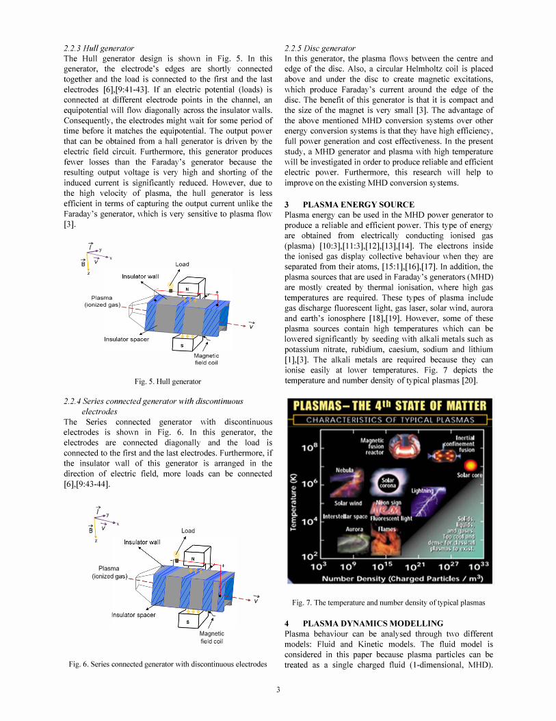
2.2.3 Hull generator The Hull generator design is shown in Fig. 5. In this generator, the electrode's edges are shortly connected
together and the load is connected to the first and the last
electrodes [6],[9:41-43]. If an electric potential (loads) is connected at different electrode points in the channel, an
equipotential will flow diagonally across the insulator walls.
Consequently, the electrodes might wait for some period of
time before it matches the equipotential. The output power
that can be obtained from a hall generator is driven by the
electric field circuit. Furthermore, this generator produces
fewer losses than the Faraday's generator because the resulting output voltage is very high and shorting of the
induced current is significantly reduced. However, due to the high velocity of plasma, the hull generator is less
efficient in terms of capturing the output current unlike the
Faraday's generator, which is very sensitive to plasma flow [3].
i y
�x B v
Plasma (ionized 9as)_
Load
Magnetic field coil
Fig. 5. Hull generator
-> -- v
2.2.4 Series connected generator with discontinuous electrodes
The Series connected generator with discontinuous electrodes is shown in Fig. 6. In this generator, the
electrodes are connected diagonally and the load is
connected to the first and the last electrodes. Furthermore, if the insulator wall of this generator is arranged in the
direction of electric field, more loads can be connected
[6],[9:43-44].
1 y
-S-x B v
Plasma (ionized gasl-
Load
....
2.2.5 Disc generator In this generator, the plasma flows between the centre and edge of the disc. Also, a circular Helmholtz coil is placed
above and under the disc to create magnetic excitations,
which produce Faraday's current around the edge of the
disc. The benefit of this generator is that it is compact and the size of the magnet is very small [3]. The advantage of
the above mentioned MHD conversion systems over other energy conversion systems is that they have high efficiency,
full power generation and cost effectiveness. In the present
study, a MHD generator and plasma with high temperature
will be investigated in order to produce reliable and efficient electric power. Furthermore, this research will help to
improve on the existing MHD conversion systems.
3 PLASMA ENERGY SOURCE
Plasma energy can be used in the MHD power generator to
produce a reliable and efficient power. This type of energy are obtained from electrically conducting ionised gas
(plasma) [10:3],[11:3],[12],[13],[14]. The electrons inside
the ionised gas display collective behaviour when they are separated from their atoms, [15: 1],[16],[17]. In addition, the
plasma sources that are used in Faraday's generators (MHD)
are mostly created by thermal ionisation, where high gas
temperatures are required. These types of plasma include gas discharge fluorescent light, gas laser, solar wind, aurora
and earth's ionosphere [18],[19]. However, some of these plasma sources contain high temperatures which can be
lowered significantly by seeding with alkali metals such as
potassium nitrate, rubidium, caesium, sodium and lithium
[1],[3]. The alkali metals are required because they can
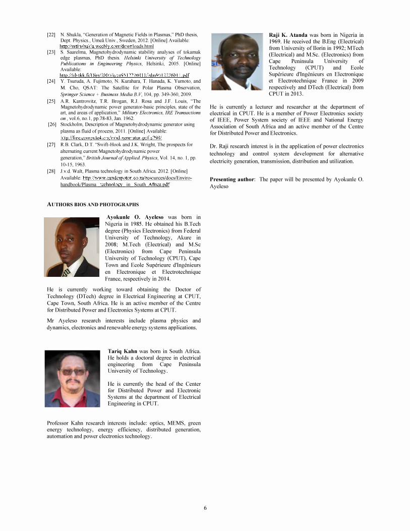
ionise easily at lower temperatures. Fig. 7 depicts the
temperature and number density of typical plasmas [20].
- .... v Fig. 7. The temperature and number density of typical plasmas
Magnetic field coil
Fig. 6. Series connected generator with discontinuous electrodes
3
4 PLASMA DYNAMICS MODELLING
Plasma behaviour can be analysed through two different
models: Fluid and Kinetic models. The fluid model is
considered in this paper because plasma particles can be
treated as a single charged fluid (I-dimensional, MHD).

These particles (electrons, ions and neutral gas) move with
the same velocity and their dynamics are governed by the
combination of Maxwell's and Navier-Stokes equations
(differential approximations). In addition, the Maxwell's and Navier-Stokes equations are usually used to describe
the MHD model of magnetized plasma and the related
electric and magnetic fields inside a medium. These
equations are thus given by [21 :9],[22],
a). MHD plasma description:
• Mass continuity:
• Momentum:
• Ohm's law:
ap +v.(pv)=O at (4)
(5)
(6)
where 17 = meVe) n/ is the plasma or spritzer resistivity,
me is the electron mass, ne is the electron density and ne 2 is the electron-ion collision frequency.
b). Maxwell's equations for MHD:
• Faraday's law:
However, in the presence of electron-ion collisions, particles
resistivity and magnetic fields exists in the plasma [22]. The conditions that are required for using the above 1-
dimensional MHD equations can be summed up to three assumptions [23].
• The radius of the ion gyro must be very small compared
to the characteristic length scale of MHD conditions. •
• The ion and electron temperatures must be equal so that
collision between them is large and viscous effects must also be ignored.
•
• The plasma or spritzer resistivity should be small to
avoid resistive diffusion.
In the subsequent studies, the study of plasma dynamics
with respect to the 2-dimensional MHD model will be
investigated using computational fluid dynamics (CFD)
software such as ansys fluent and Comsot.
5 PAST AND PRESENT RESEARCH ON PLASMA
TECHNOLOGY
Plasma dynamics and behaviours have been investigated through developing and sending of probing instruments to
space. One of these instruments is a high frequency
Langmuir probe on-board QSA T satellite which was
developed by the engineers at the laboratory of spacecraft
environment interaction, Kyushu Institute of Technology, Japan. The main objectives of the QSA T satellite are to
investigate the plasma within the Aurora region, and to have
a better understanding of the spacecraft charging caused by energetic particles in this region [24]. The present study also
reviewed some other experiments in order to understand the characteristics of different types of MHD generators. These
experiments are given as below,
• A segmented MHD generator was developed at the
A vco-Everett Research Laboratory, Massachusetts. The aB --=-VxE at
• Charge continuity:
(7) plasma source used inside this generator was a Jet Propellant
(JP4) and the seeded gases used were potassium carbonate
(K2C03) and potassium hydroxide (KOH). An output power
of about 93 kW was obtained from each single electrode of
the generator. The outcomes of this experiment showed that
VXJ=O
• Ampere's law:
(8) gases from the conventional heat sources can be made with
adequate conductors of electricity in MHD generator,
provider that a small amount of easily ionisable seeded
impurities is added to the gas. In addition, the use of
segmented electrodes help to reduce hall current and also
(9) encourages further studies on the power distributed across
the segmented electrode channels of the generator [25].
From equations (4) to (9), the plasma state is assumed to be
in collisionless because magnetic fields lines of force seem to be frozen inside the plasma. Hence, the plasma resistivity
for an ideal plasma state condition is equal to zero, 17 = 0 .
4
• Another experiment was also conducted by A YCO
Mark 11 in the United State. The focus of their research was
to build a segmented electrode MHD generator that
produces 1.5 MW as electrical power for short time duration
(10 seconds). The plasma source used inside the generator
was Methycyclohexane (3000° K) and the seeded gas used
was potassium hydroxide (KOH) [26].

• In the 60's, an experiment was also conducted by
Lindsey at the international research and development company, Newcastle, England. The focus of his research
was to understand what kind of efficiency can be obtained
with the combined use of segmented electrode MHD
generator and a closed loop cycle turbine steam system. The plasma source used was Helium, He, (1500° K - 2500° K) and the seeded gas used was caesium, Cs [26].
• An experiment was also conducted on inductor AC
MHD generator by swift-Hook, Clark and Wright. The
focus of their research was to build an inductor AC MHD
generator which was tested with different gas temperatures
(2000° K, 2500° K and 3000° K). Their conclusions were
that this method requires more energy to produce the needed
magnetic field. As a result, the experiment is not cost
effective [26],[27].
Considering plasma technologies in South Africa, plasma
are used for treatments of minerals, welding, surface
treatment, silicon etching and metal alloy manufacturing.
Furthermore, plasma is used nowadays as a new system of waste treatments (gasification method). This method
replaces the previously used incineration system. The
plasma assisted gasification is used to produce carbon
synthesis gas, which can be converted into petrol for the generation of electricity [28]. However, with the increasing
demand of electricity in South Africa, the present research
aims to conduct more investigation on plasma dynamics using faraday'S segmented electrodes with a rectangular
duct channel. This investigation will be based on improving
the existing methods of converting plasma energy directly to
electric power.
6 CONCLUSION
The principle of MHD has been reviewed extensively in this
paper and an MHD generator with segmented electrodes is
considered for further investigation and development. The
selection of segmented electrodes with rectangular duct
channel is based on its numerous advantages over other
types of generators. Furthermore, in order to design an
efficient segmented MHD generator, a good knowledge of the electrical conductivity of the working plasma fluid and
its variation with temperature and pressure is required. The conductivity of such plasma gas fluid determines the amount
of power to be generated and also the quantity of magnet to
be used in the segmented MHD generator. Additionally, a superconducting magnet must be used inside the MHD
generator in order to achieve good output power efficiency.
The combustion plasma gas fluid can also be delivered by any heat source with peak temperatures slightly greater than
3000oK. This type of gas is not suitable for use in an MHD
generator unless it is seeded with a small amount of easily ionisable impurity such as potassium salt or caesium. The
use of seeding gas is required because most plasma fluid at
high temperatures do not have sufficient electrical
conductivity .
5
REFERENCES [I] K.R. Ajith, and B.S. Jinshah, "Magnetohydrodynamic Power
Generation, " International Journal of Scientific and Research
Publications, vo\. 3, no. 6, pp. I-I I, 2013. '
[2] M.C. Anumaka, "Explicit Technology of Magnetohydrodynamic
(Mhd) Power Generation, " International Journal of Innovative
Technology and Research, vo\. 2, no.4, pp.IOn-I077, 2014.
[3] B. Masood, M.H. Riaz and M. Yasir, "Integration of
Magnetohydrodynamics (MHD) Power Generating Technology with
Thermal Power Plants for Efficiency Improvement, " World Applied
Sciences Journal, vo\. 32, no.7, pp.1356-1363, 2014.
[4] R. M. Mayo and R. L. Mills, Direct Plasmadynamic Conversion of
Plasma Thermal Power to Electricity for Microdistributed Power
Applications, In 40th Annual Power Sources Conference, 2002,
pp.l-4.
[5] MA Khan, K. Vaddadi, A. Gupta and k. Vigneshwara, "Case Study
of MHO Generator for Power Generation and High Speed
Propulsion, " International Journal Of Modern Engineering
Research, vo\. 4, no.9, pp.81-90, 2014.
[6] R. Sedaghati, A.R. Rajabi, H. Sedaghati and M.M. Tazangi, "A New
Technology for Power Generation Based on Kinetic Energy of the
Plasma, " International Journal of scientific research and
management, vo\. I, no.5, pp. 281-284, 2013.
[7] P. Li, G. Barry, S. Castellanos, C. Chan, K. Do, C. Gamez, J. Kuhn and A. Leon, Power Generation Using Magnetohydrodynamic Generator with a Circulation Flow Driven by Solar-Heat-Induced Natural Convection.2007. [Online] Available: http: //cfpub.epa.gov/ncer abstracts/index.cfm/fuseaction/display.hig hI ight/abstract/8630/reportlF
[8] Y. Ok uno, K. Watanabe, A. Kawasaki, and T. Murakami,
Experimental Studies of Seed-Free Pure-Inert-Gas Working MHD
Power Generation, In 42nd AIAA Plasmadynamics and Lasers
Conference, 2011, pp.l-7.
[9] M.S. Tillack and N.B. Morley, "Magnetohydrodynam- ics, " in
Magnetohydrodynamics Standard Handbook for Electrical
Engineers, 14th ed., New York, McGraw- Hill, 1998, pp. 1-88.
[10] F.F. Chen, Introduction to plasma physics and controlledjilsion. 2nd
ed., New York: Plenum Press, 1984, pp. 1-421.
[11] A. Grill, Cold plasma in materials fabrication:fromjimdamentals to
applications. New York: I EEE Press, 1994, pp. 1-2n.
[12] C. Weyde, "Plasma parameters from the Rosetta LAP instrument, "
MSc thesis, Dept. Physics., Uppsala Univ., Sweden, 2006.
[13] A.C. Escobar, A "Langmuir probe instrument for research in the
terrestrial Ionosphere, " MSc thesis, Dept. Elect. Eng., Pennsylvania
State Univ., United State, 2009.
[14] DJ. Asselin, "Characterization of the near-plume region of a low
current hollow cathode, " MSc thesis, Dept. Mech. Eng., Worcester
Poly. Inst., Worcester, 2011.
[15] K. Miyamoto, Fundamentals of plasma physics and controlled
jilsion. Tokyo: Iwanami Book Service Center, 2000, pp. 1-348.
[16] J. Bohlmark, "Fundamentals of High Power Impulse Magnetron
Sputtering, " PhD thesis, Dept. Physics., Linkoping University,
Linkoping, Sweden, 2006.
[17] H.O. Rucker. (2008). Introduction to Plasma Physics. Inst. Physics.,
Karl-Franzens Univ. Austria. [Onlinel Available:
ftp: //ftp. iwf. oeaw. ac. at/pu b/pel/pl as ma%20phys ics. pdf
[18] A. Bogaerts, E. Neyts, R. Gijbels and J.v.d. Mullen, "Gas discharge
plasmas and their applications, " Spectrochimica Acta Part B, vo\. 57,
pp. 609-65, 2002.
[19] H. Yongcheol and S.U. Han, Plasma Flame Sustained by
Microwaves and Burning Hydrocarbon Fuel: It's Applications, In
InTech [online l Available:
www.intechopen.com/download/pdf/I1345
[20] J. Edson and H. Cohen, Plasmas - the Fourth State of Matter:
Characteristics of Typical Plasmas, In CPEP Fusion Energy
Education Web [onlinel Available:
http: //fusedweb.llnl.gov/CPEP/Chart Pages/5.Plasma4StateMatter.ht
ml
[21] J.D. Call en, Fundamentals of Plasma Physics. Madison: University
of Wisconsin, 2003, pp. 1-34.
[22] N. Shukla, "Generation of Magnetic Fields in Plasmas, " PhD thesis, Dept. Physics., Umea Univ., Sweden, 2012. [Online] Available: http: //nitinshukla.weebly.com/down loads. html
[23] S. Saarelma, Magnetohydrodynamic stability analyses of tokamak edge plasmas, PhD thesis. Helsinki University of Technology
Publications in Engineering Physics, Helsinki, 2005. [On line] Available: http://lib.tkk.fi/Diss/2005Iisbn95122760 11 /isbn9512276011.pdf
[24] Y. Tsuruda, A. Fujimoto, N. Kurahara, T. Hanada, K. Yumoto, and
M. Cho, QSA T: The Satellite for Polar Plasma Observation,
Springer Science + Business Media B. V, 104, pp. 349-360, 2009.
[25] A.R. Kantrowitz, T.R. Brogan, R.J. Rosa and IF. Louis, 'The Magnetohydrodynamic power generator-basic principles, state of the art, and areas of application, " Military Electronics, IRE Transactions
on , vol.6, no. I , pp.78-83, Jan. 1962. [26] Stockholm, Description of Magnetohydrodynamic generator using
plasma as fluid of process, 2011. [Online] Available:
http: //free.compute4.orgfmhd-generator-pdf-s290/
[27] R.B. Clark, D.T. "Swift-Hook and J.K. Wright, The prospects for
alternating current Magnetohydrodynamic power
generation, " BrilishJournal of Applied. Physics, Vol. 14, no. 1, pp.
10-15, 1963.
[28] J.v.d. Wait, Plasma technology in South Africa. 2012. [Online]
A vai I abl e: http://www.eandcspoton.co.zaireso urces/ docslEnvi ro
handbook/Plasma technology in South Africa.pdf
AUTHORS BIOS AND PHOTOGRAPHS
Ayokunle O. Ayeleso was born in
Nigeria in 1985. He obtained his B.Tech
degree (Physics Electronics) from Federal
University of Technology, Akure in
2008; M.Tech (Electrical) and M.Sc
(Electronics) from Cape Peninsula
University of Technology (CPUT), Cape
Town and Ecole Superieure d'Ingenieurs
en Electronique et Electrotechnique
France, respectively in 2014.
He is currently working toward obtaining the Doctor of
Technology (DTech) degree in Electrical Engineering at CPUT,
Cape Town, South Africa. He is an active member of the Centre
for Distributed Power and Electronics Systems at CPUT.
Mr Ayeleso research interests include plasma physics and
dynamics, electronics and renewable energy systems applications.
Tariq Kahn was born in South Africa. He holds a doctoral degree in electrical engineering from Cape Peninsula University of Technology.
He is currently the head of the Center for Distributed Power and Electronic Systems at the department of Electrical Engineering in CPUT.
Professor Kahn research interests include: optics, MEMS, green energy technology, energy efficiency, distributed generation,
automation and power electronics technology.
6
Raji K. Atanda was born in Nigeria in 1969. He received the B.Eng (Electrical)
from University ofIlorin in 1992; MTech (Electrical) and M.Sc. (Electronics) from
Cape Peninsula University of
Technology (CPUT) and Ecole Superieure d'Ingenieurs en Electronique et Electrotechnique France in 2009
respectively and DTech (Electrical) from CPUT in 2013.
He is currently a lecturer and researcher at the department of electrical in CPUT. He is a member of Power Electronics society of IEEE, Power System society of IEEE and National Energy
Association of South Africa and an active member of the Centre
for Distributed Power and Electronics.
Dr. Raji research interest is in the application of power electronics
technology and control system development for alternative
electricity generation, transmission, distribution and utilization.
Presenting author: The paper will be presented by Ayokunle O. Ayeleso