

Plant Management, Engineer- ing & Operations Conference ... · duce effective steam turbine...
212
San Juan College Farmington, NM August 1-2, 2018 Plant Management, Engineer- ing & Operations Conference, Roundtable and Mine Tour Instructed by: Tom Reid, Manager of Engineering, TG Advisers Gary Ruhl, Manager, Fuels & Technical Services, Omaha Public Power District Jake Schmitter, Sr. Manager, Training & Exercises, Electricity Information Sharing and Analysis Center Ryan Walter, Compliance Analyst, Tri-State Generation & Transmission Association Thomas Livingston, Plant Manager, Four Corners Power Plant, Arizona Public Service Bill Paiz, Power Production Engineer V, PNM Resources Saul Macias, Power Production Engineer, PNM Resources Luke Buntz, Market Research Analyst, Mitsubishi Hitachi Power Systems Americas, Inc. Phil Duran, Sr. Director , Business Operations, Tyr Energy, Inc. Brad Buecker, Sr. Technical Publicist, ChemTreat RMEL ~ 6855 S. Havana, Ste 430 ~ Centennial, CO 80112 ~ (303) 865-5544 ~ FAX: (303) 865-5548 ~ www.RMEL.org
Transcript of Plant Management, Engineer- ing & Operations Conference ... · duce effective steam turbine...
San Juan CollegeFarmington, NM
August 1-2, 2018
Plant Management, Engineer-ing & Operations Conference, Roundtable and Mine Tour
Instructed by:Tom Reid, Manager of Engineering, TG Advisers
Gary Ruhl, Manager, Fuels & Technical Services, Omaha Public Power District Jake Schmitter, Sr. Manager, Training & Exercises, Electricity Information Sharing and Analysis Center
Ryan Walter, Compliance Analyst, Tri-State Generation & Transmission Association Thomas Livingston, Plant Manager, Four Corners Power Plant, Arizona Public Service
Bill Paiz, Power Production Engineer V, PNM Resources Saul Macias, Power Production Engineer, PNM Resources
Luke Buntz, Market Research Analyst, Mitsubishi Hitachi Power Systems Americas, Inc.Phil Duran, Sr. Director , Business Operations, Tyr Energy, Inc.
Brad Buecker, Sr. Technical Publicist, ChemTreat
RMEL ~ 6855 S. Havana, Ste 430 ~ Centennial, CO 80112 ~ (303) 865-5544 ~ FAX: (303) 865-5548 ~ www.RMEL.org

Wednesday, August 1, 20188:00 a.m. – 8:15 a.m.Welcome and Introductions
8:15 a.m. – 9:15 a.m.Turbine Troubleshooting and Repair MethodsTom Reid, Manager of Engineering, TG AdvisersThis presentation will intro-duce effective steam turbine troubleshooting strategies and highlight cost effective repair strategies. New issues manifesting from increased unit cycling and turndown will also be discussed along with the pitfalls of associ-ated equipment issues. An understanding of these failure modes, and how to prevent them, will help plant personnel avoid costly forced outages.
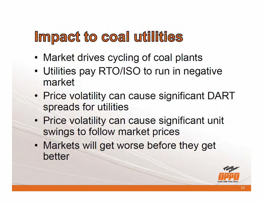
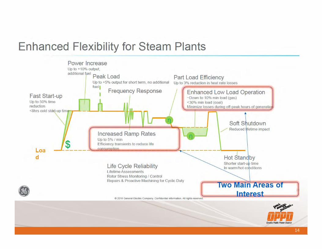
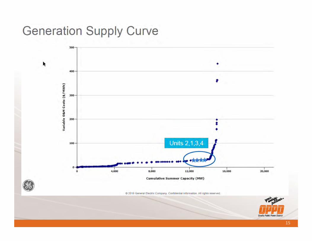
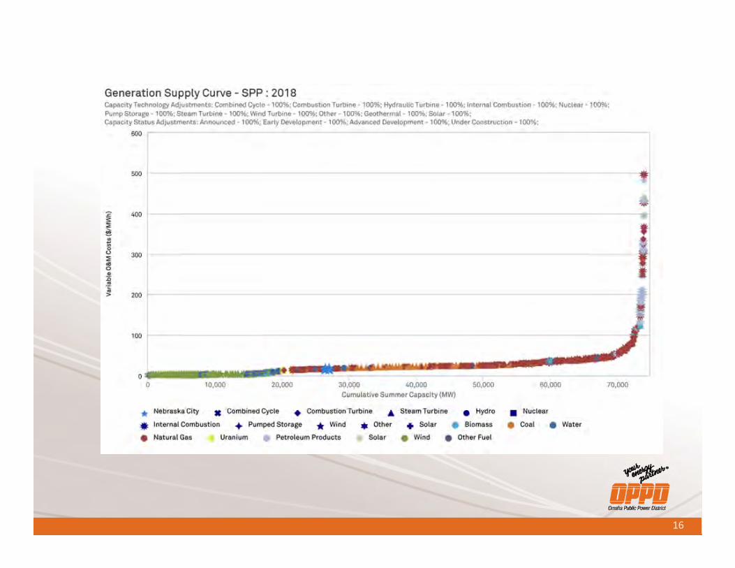
9:15 a.m. – 10:00 a.m.Steam Power Plant Cycling Symposium UpdateGary Ruhl, Manager, Fuels & Technical Services, Omaha Public Power DistrictThis presentation will provide an update and summary of the recent Steam Power Plant Cycling Symposium. The symposium had extreme utility interest and success in covering real-world impacts of energy market changes that are creating cycling operating conditions for traditionally based-loaded steam power plants. Both the operational environment and consequences of cycling will be covered. Cycling has caused a monumental shift in operating practices in an effort to remain competitive in the energy markets with depressed natural gas pricing and renewables penetration. Specific examples of the changes occurring, impacts,
and actions being pursued will be summarized. The evolving energy markets are driving these changes in an effort for sustained viability of core generating assets.
10:00 a.m. - 10:15 a.m.Networking Break
10:15 a.m. - 11:00 a.m.GridEx IV After Action Report and Lessons LearnedJake Schmitter, Senior Manager, Training & Exercises, Electricity Information Sharing and Analysis CenterThe presentation will go over the GridEx IV background information: scenario, partici-pation metrics and exercise construct. The lessons learned portion will highlight known issues, incident response gaps identified within the Electric-ity Industry and ways forward for GridEx V.
11:00 a.m. - 11:45 a.m.Low Impact Generation CIP ComplianceRyan Walter, Compliance Analyst, Tri-State Generation & Transmission AssociationThis presentation will cover NERC Low impact compli-ance in its entirety for Gen-eration facilities. Mr. Walter will discuss the evolution of the CIP standards through the years and the introduc-tion of the High, Medium, and Low classifications. He will cover what specifically is required by the regulation CIP-003-7 for Low Impact assets. Finally, he will discuss and show what Tri-State has done or will be doing to comply with the require-ments.
11:45 a.m. – 1:00 p.m.Networking Lunch
1:00 p.m. - 1:45 p.m.Physical Security (Suspi-cious Package Handling)Thomas Livingston, Plant Manager, Four Corners Power Plant, Arizona Public Service
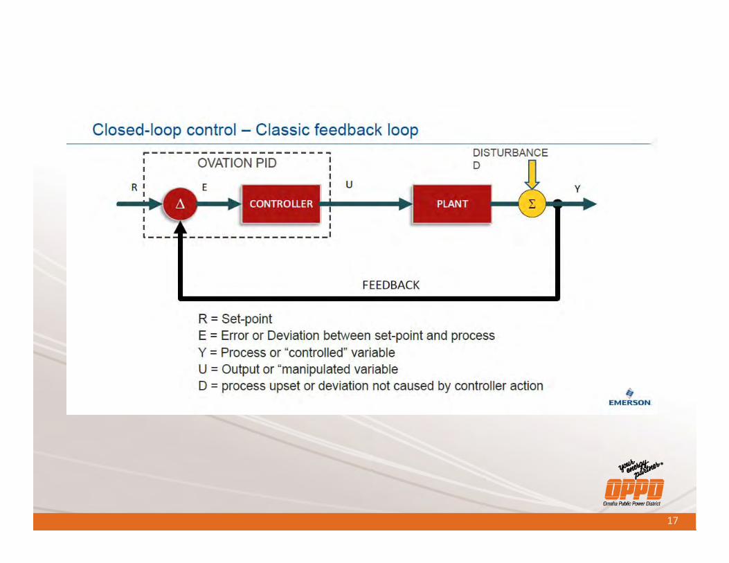
1:45 p.m. - 2:30 p.m.NERC BAL-003 – Frequency Response Impacts on PlantsBill Paiz, Power Production Engineer V, and Saul Macias, Power Production Engineer, PNM ResourcesFrequency response has been a WECC requirement for generators for several years. Over the last two years, the issue has become more critical because of the transition of conventional boiler- fired generating units to renewables (wind and solar) so a NERC standard was developed to address this issue. The new standard defined the required fre-quency response required for each control area. The renewables do not have the stored energy required to support the frequency excur-sions. All older generator control systems have been installed with automatic drop control which provides for frequency stability. With the addition of state-of-the-art control system, this has become a challenge because these new control systems were designed for set point control. During a frequency excursion, the new control system would override the drop control thus driving the unit back to set point. In our presentation, we will dem-onstrate how PNM overcame those control issues.
2:30 p.m. - 2:45 p.m.Networking Break
CONFERENCE AgENdA2:45 p.m. - 3:00 p.m.Attendee AnnouncementsAny registered attendee is invited to make a short announcement on their com-pany, new products, technolo-gies or informational updates. Announcements may include showing a product sample but not videos and power point slides. Please limit an-nouncement to 5 minutes.
3:00 p.m. - 3:30 p.m.Four Corners Plant OverviewThomas Livingston, Plant Manager, Four Corners Power Plant, Arizona Public Service
3:30 p.m. - 4:30 p.m.Generation Vital Issues RoundtableBring roundtable topics for discussion and/or send topics ahead of time to [email protected]. Roundtables offer a unique forum for peer-to-peer shar-ing of experiences, critical issues and expertise. The roundtable is a discussion group, open only to RMEL members. Discussion is based on topics brought by attendees. Roundtables are focused on the open discus-sion period and provide each attendee the oppor-tunity for participation and dialogue on their particular issue. Roundtables are held in conjunction with a conference and many topics presented at the conference are discussed further in the roundtable setting. The roundtable is a good oppor-tunity to share experiences, troubleshoot problems and network with peers in a smaller, informal setting. Each participant is offered a chance to pose questions and share information. All attendees are encouraged to bring issues for discussion and materials for sharing.
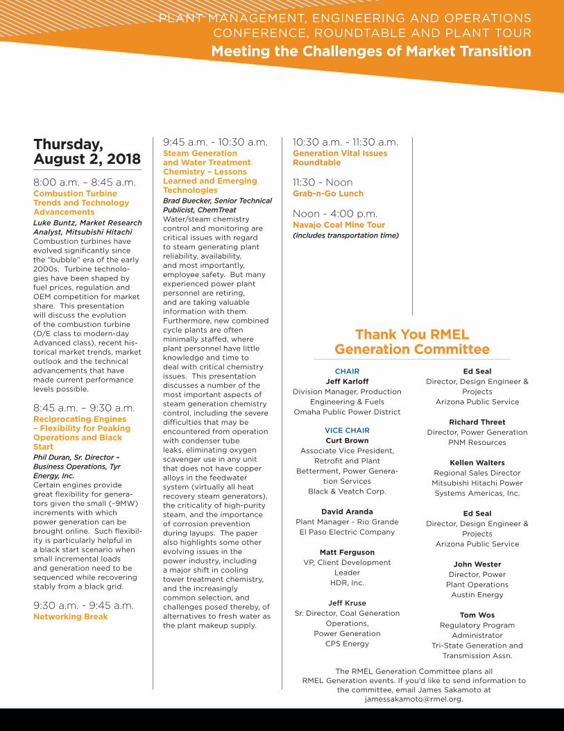
Thursday, August 2, 20188:00 a.m. – 8:45 a.m.Combustion Turbine Trends and Technology AdvancementsLuke Buntz, Market Research Analyst, Mitsubishi HitachiCombustion turbines have evolved significantly since the “bubble” era of the early 2000s. Turbine technolo-gies have been shaped by fuel prices, regulation and OEM competition for market share. This presentation will discuss the evolution of the combustion turbine (D/E class to modern-day Advanced class), recent his-torical market trends, market outlook and the technical advancements that have made current performance levels possible.
8:45 a.m. – 9:30 a.m.Reciprocating Engines – Flexibility for Peaking Operations and Black StartPhil Duran, Sr. Director – Business Operations, Tyr Energy, Inc.Certain engines provide great flexibility for genera-tors given the small (~9MW) increments with which power generation can be brought online. Such flexibil-ity is particularly helpful in a black start scenario when small incremental loads and generation need to be sequenced while recovering stably from a black grid.
9:30 a.m. - 9:45 a.m.Networking Break
9:45 a.m. - 10:30 a.m.Steam Generation and Water Treatment Chemistry – Lessons Learned and Emerging TechnologiesBrad Buecker, Senior Technical Publicist, ChemTreatWater/steam chemistry control and monitoring are critical issues with regard to steam generating plant reliability, availability, and most importantly, employee safety. But many experienced power plant personnel are retiring, and are taking valuable information with them. Furthermore, new combined cycle plants are often minimally staffed, where plant personnel have little knowledge and time to deal with critical chemistry issues. This presentation discusses a number of the most important aspects of steam generation chemistry control, including the severe difficulties that may be encountered from operation with condenser tube leaks, eliminating oxygen scavenger use in any unit that does not have copper alloys in the feedwater system (virtually all heat recovery steam generators), the criticality of high-purity steam, and the importance of corrosion prevention during layups. The paper also highlights some other evolving issues in the power industry, including a major shift in cooling tower treatment chemistry, and the increasingly common selection, and challenges posed thereby, of alternatives to fresh water as the plant makeup supply.
PLANT MANAGEMENT, ENGINEERING AND OPERATIONS CONFERENCE, ROuNDTABLE AND PLANT TOuR
Meeting the Challenges of Market Transition
Thank You RMEL Generation CommitteeCHAIR
Jeff KarloffDivision Manager, Production
Engineering & FuelsOmaha Public Power District
VICE CHAIRCurt Brown
Associate Vice President, Retrofit and Plant
Betterment, Power Genera-tion Services
Black & Veatch Corp.
David ArandaPlant Manager - Rio GrandeEl Paso Electric Company
Matt FergusonVP, Client Development
LeaderHDR, Inc.
Jeff KruseSr. Director, Coal Generation
Operations, Power Generation
CPS Energy
The RMEL Generation Committee plans all RMEL Generation events. If you’d like to send information to
the committee, email James Sakamoto at [email protected].
Ed SealDirector, Design Engineer &
Projects Arizona Public Service
Richard ThreetDirector, Power Generation
PNM Resources
Kellen WaltersRegional Sales DirectorMitsubishi Hitachi Power Systems Americas, Inc.
Ed SealDirector, Design Engineer &
Projects Arizona Public Service
John WesterDirector, Power
Plant OperationsAustin Energy
Tom WosRegulatory Program
AdministratorTri-State Generation and
Transmission Assn.
10:30 a.m. - 11:30 a.m.Generation Vital Issues Roundtable
11:30 - Noon Grab-n-Go Lunch
Noon - 4:00 p.m.Navajo Coal Mine Tour(includes transportation time)
Turbine Troubleshooting and Repair Methods
Tom Reid Manager of Engineering
TG Advisers
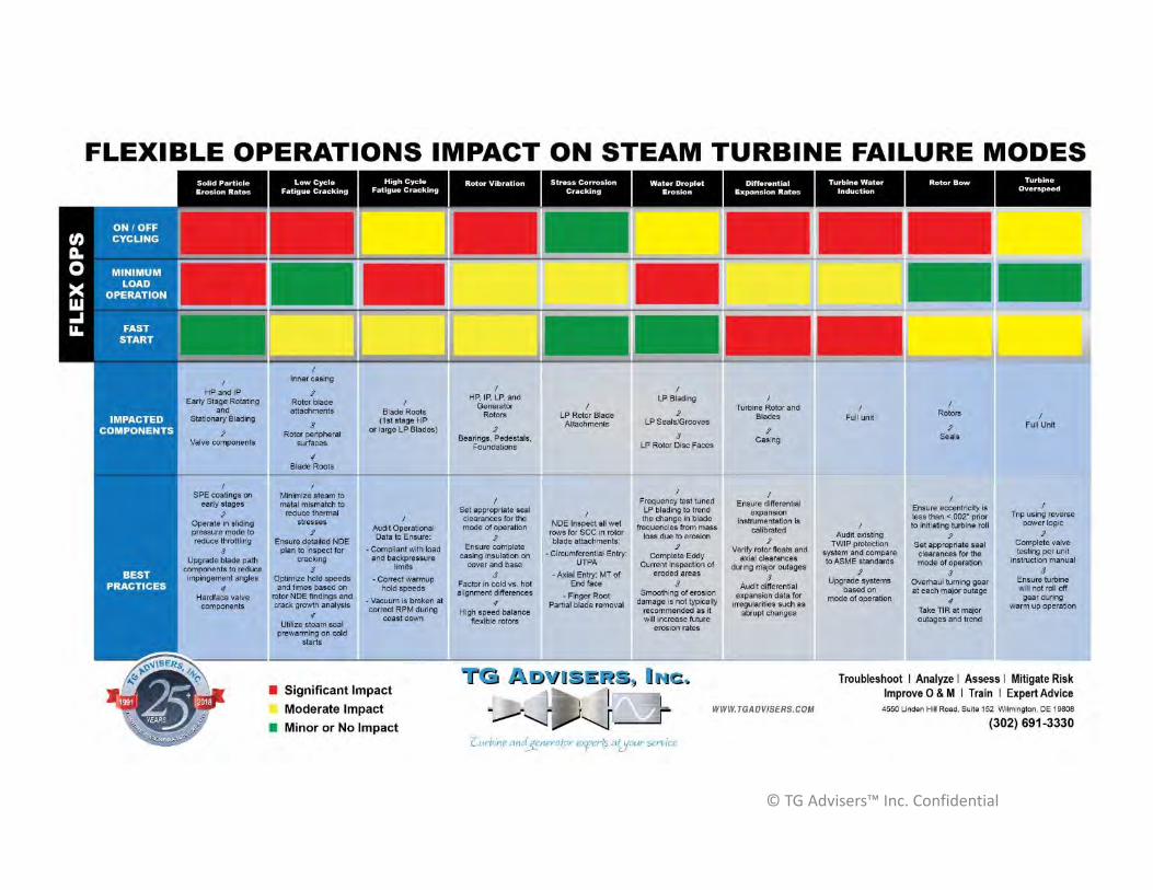
Flexible Operations Impact on Steam Turbine Failure Modes and Best Practices
Thomas R. Reid, P.E.Manager of Engineering
[email protected](302) 691 - 3330
August 1st, 2018
Farmington, NM
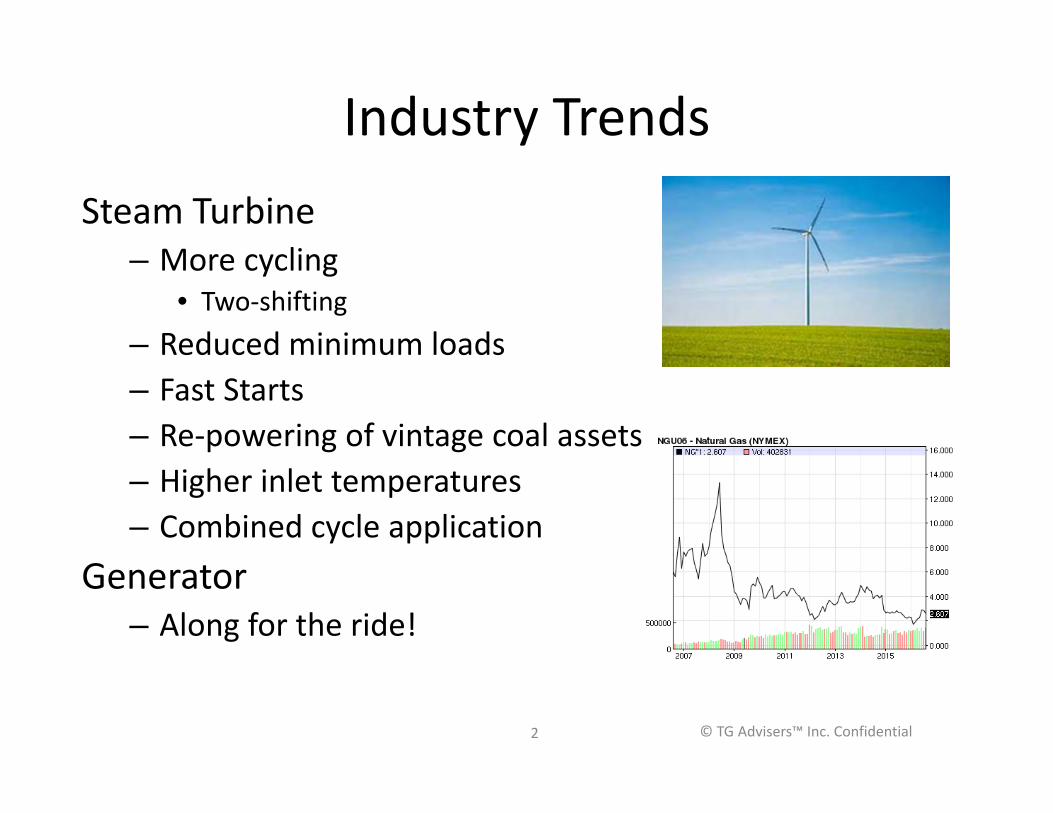
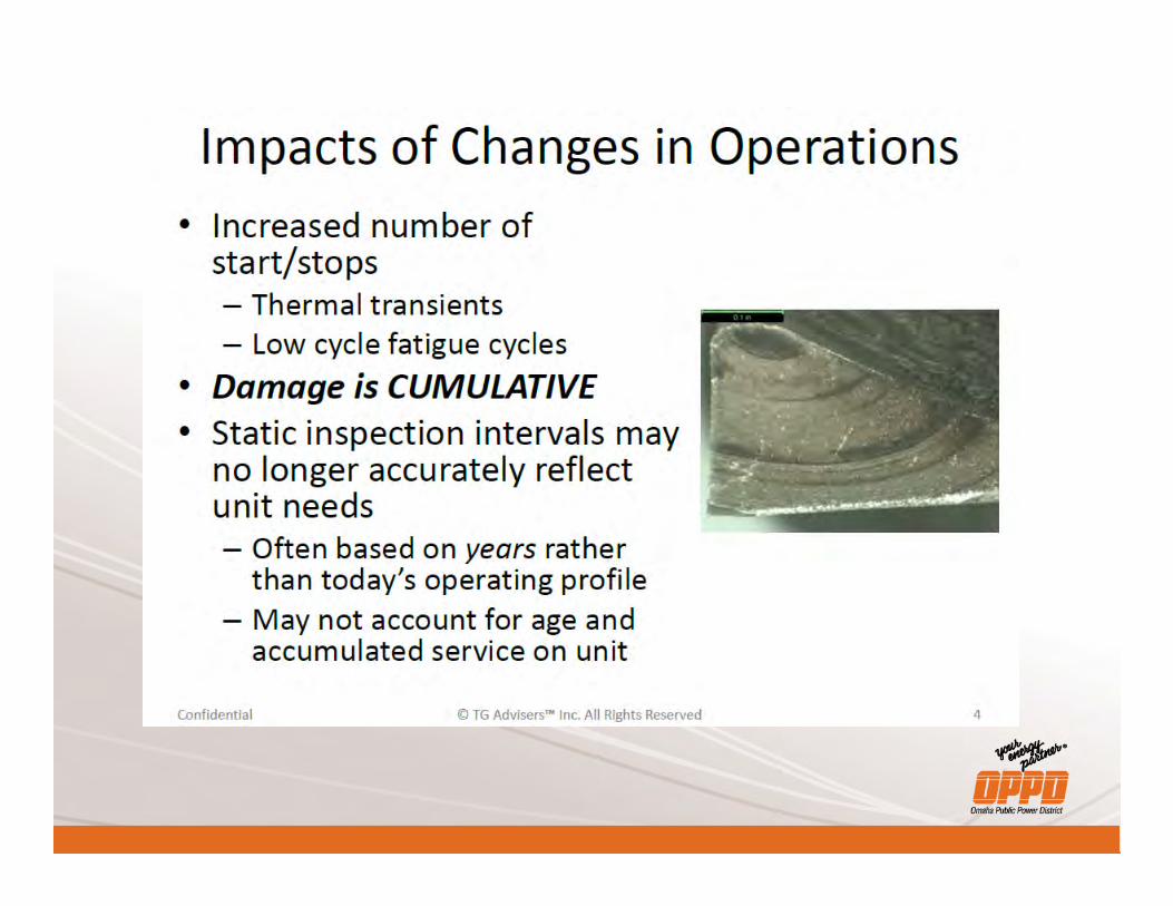
Industry Trends Steam Turbine
– More cycling• Two-shifting
– Reduced minimum loads– Fast Starts– Re-powering of vintage coal assets– Higher inlet temperatures– Combined cycle application
Generator – Along for the ride!
© TG Advisers™ Inc. Confidential2
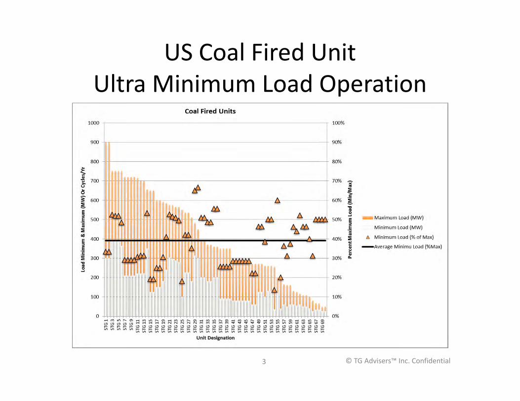
US Coal Fired UnitUltra Minimum Load Operation
© TG Advisers™ Inc. Confidential3
© TG Advisers™ Inc. Confidential

STEAM TURBINE FAILURE MECHANISMS
© TG Advisers™ Inc. Confidential
Key Steam Turbine Mechanisms
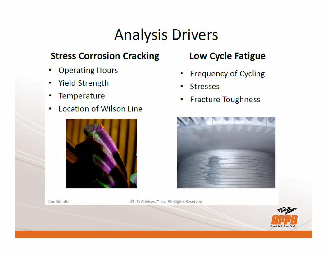
• High Cycle Fatigue – Vibration• Creep - Steady stress at elevated temperatures• Environmental - Stress Corrosion Cracking (SCC)• Low Cycle Fatigue – Thermal and mechanical Cycling • Foreign Object Damage - Flow path liberation• Embittlement – Time and temperature exposure• Erosion – Water droplet and solid particle• Rubbing – Axial and Radial • Event Driven – Water Induction, Overspeed
© TG Advisers™ Inc. Confidential
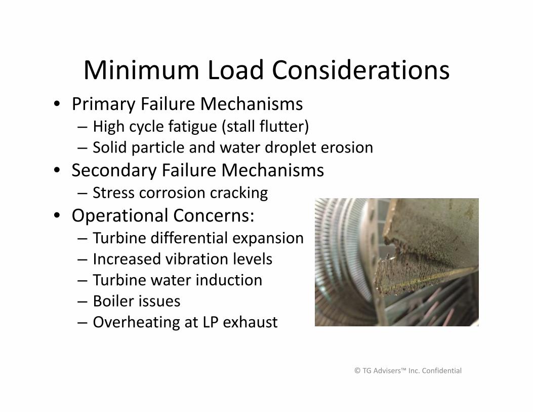
Minimum Load Considerations• Primary Failure Mechanisms
– High cycle fatigue (stall flutter)– Solid particle and water droplet erosion
• Secondary Failure Mechanisms– Stress corrosion cracking
• Operational Concerns:– Turbine differential expansion– Increased vibration levels– Turbine water induction– Boiler issues – Overheating at LP exhaust
© TG Advisers™ Inc. Confidential
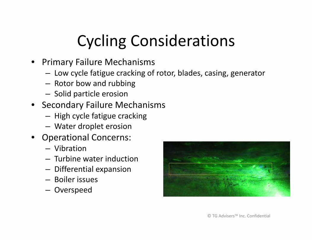
Cycling Considerations• Primary Failure Mechanisms
– Low cycle fatigue cracking of rotor, blades, casing, generator– Rotor bow and rubbing– Solid particle erosion
• Secondary Failure Mechanisms– High cycle fatigue cracking– Water droplet erosion
• Operational Concerns:– Vibration– Turbine water induction– Differential expansion– Boiler issues – Overspeed
© TG Advisers™ Inc. Confidential

HIGH CYCLE FATIGUE (HCF)
© TG Advisers™ Inc. Confidential
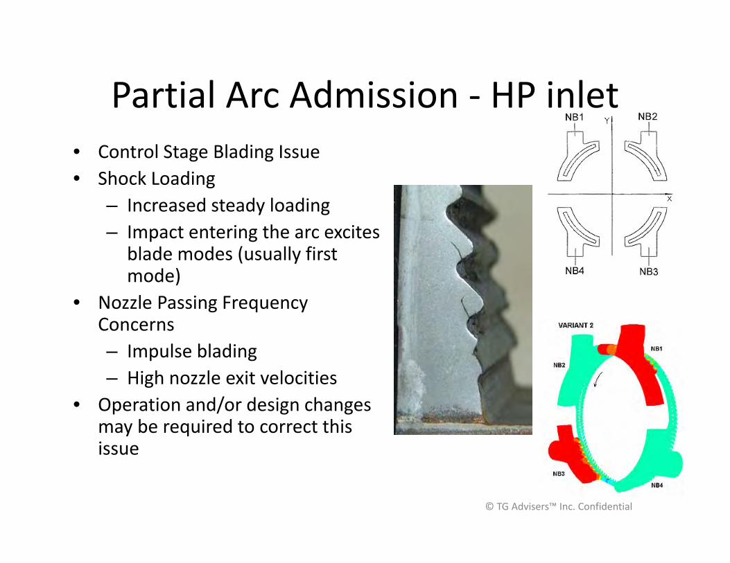
Partial Arc Admission - HP inlet• Control Stage Blading Issue• Shock Loading
– Increased steady loading– Impact entering the arc excites
blade modes (usually first mode)
• Nozzle Passing Frequency Concerns– Impulse blading– High nozzle exit velocities
• Operation and/or design changes may be required to correct this issue
© TG Advisers™ Inc. Confidential
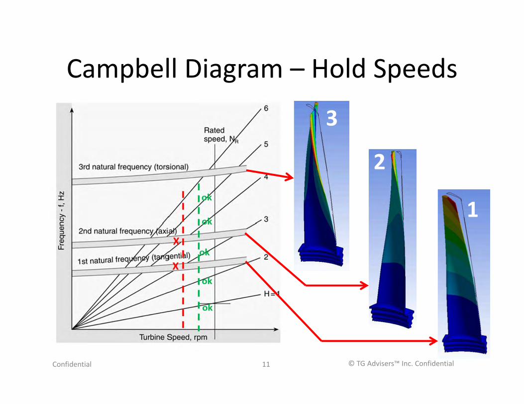
Campbell Diagram – Hold Speeds
Confidential © TG Advisers™ Inc. Confidential11
1
2
3

Stall Flutter – LP Blading• Flow separation produces vibrations • Occurs in last stage of LP under low
load and high back-pressure conditions• Conditions of concern:
– Longer blade designs with lower first blade mode frequencies
– High air in-leakage– Summer periods where
backpressure control is challenged – Potential for increase in failure
mode with shift towards load cycling
Confidential © TG Advisers™ Inc. Confidential12

EROSION – SPE AND WATER DROPLET
© TG Advisers™ Inc. Confidential
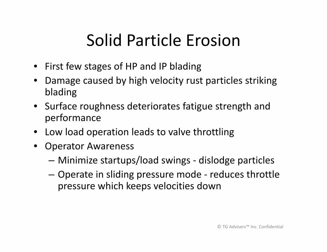
Solid Particle Erosion• First few stages of HP and IP blading• Damage caused by high velocity rust particles striking
blading• Surface roughness deteriorates fatigue strength and
performance• Low load operation leads to valve throttling• Operator Awareness
– Minimize startups/load swings - dislodge particles– Operate in sliding pressure mode - reduces throttle
pressure which keeps velocities down
© TG Advisers™ Inc. Confidential
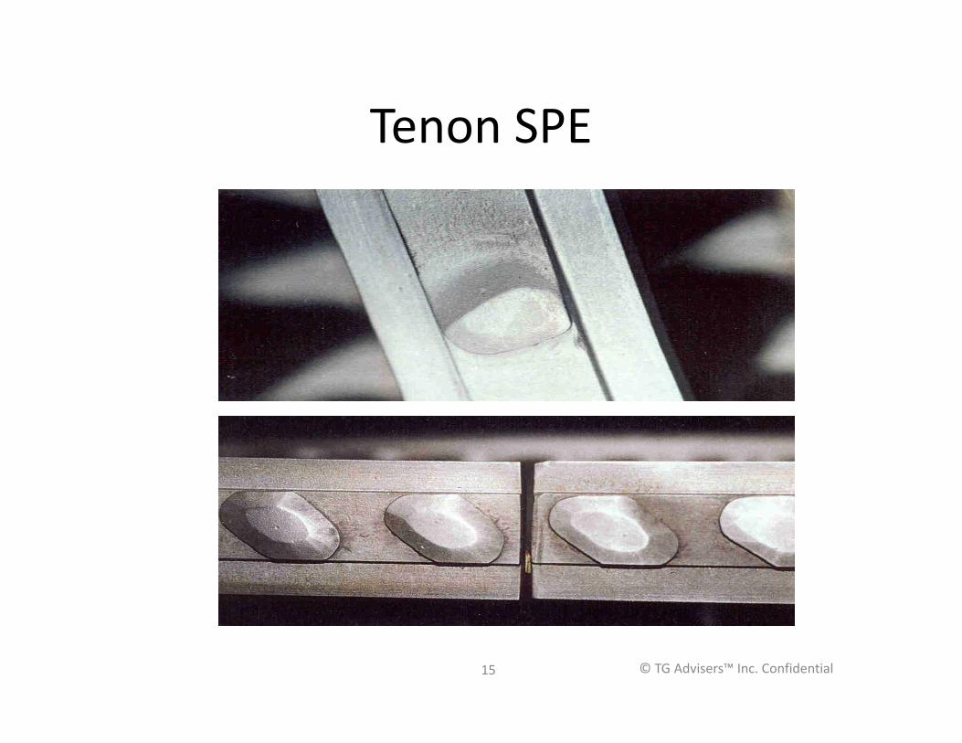
Tenon SPE
© TG Advisers™ Inc. Confidential15
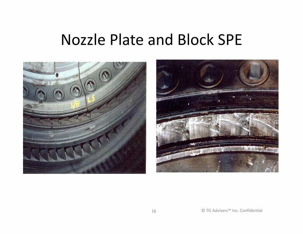
Nozzle Plate and Block SPE
© TG Advisers™ Inc. Confidential16

SPE Coatings
• Tungsten Carbide• Chromium Carbide• Titanium Nitride
© TG Advisers™ Inc. Confidential17
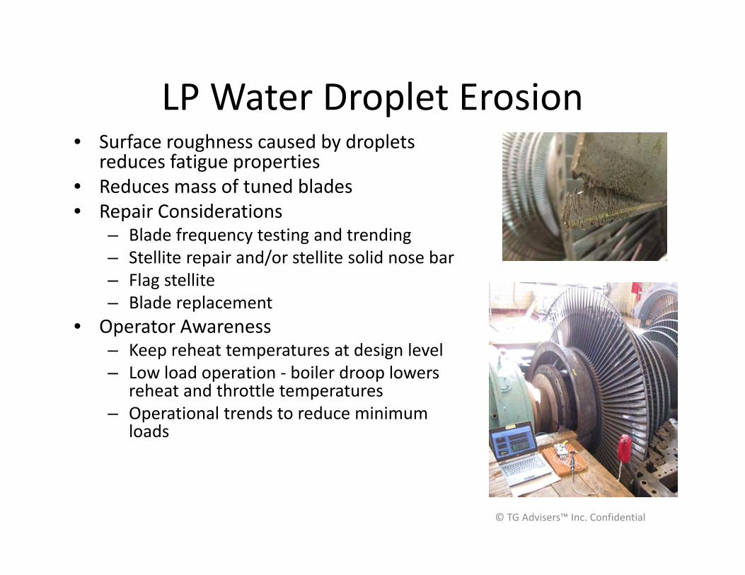
LP Water Droplet Erosion• Surface roughness caused by droplets
reduces fatigue properties• Reduces mass of tuned blades• Repair Considerations
– Blade frequency testing and trending– Stellite repair and/or stellite solid nose bar – Flag stellite– Blade replacement
• Operator Awareness– Keep reheat temperatures at design level– Low load operation - boiler droop lowers
reheat and throttle temperatures – Operational trends to reduce minimum
loads
© TG Advisers™ Inc. Confidential
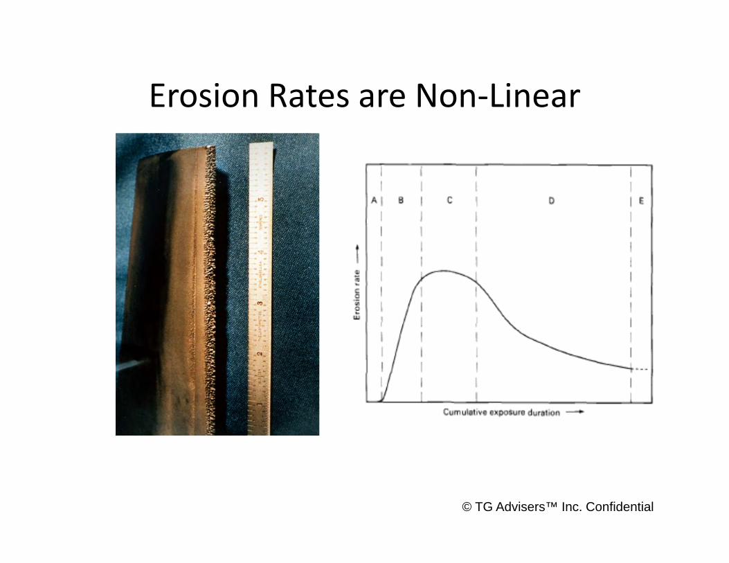
Erosion Rates are Non-Linear
© TG Advisers™ Inc. Confidential

LOW CYCLE FATIGUE
© TG Advisers™ Inc. Confidential
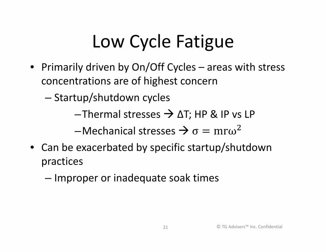
Low Cycle Fatigue• Primarily driven by On/Off Cycles – areas with stress
concentrations are of highest concern– Startup/shutdown cycles
–Thermal stresses ΔT; HP & IP vs LP–Mechanical stresses
• Can be exacerbated by specific startup/shutdown practices– Improper or inadequate soak times
© TG Advisers™ Inc. Confidential21
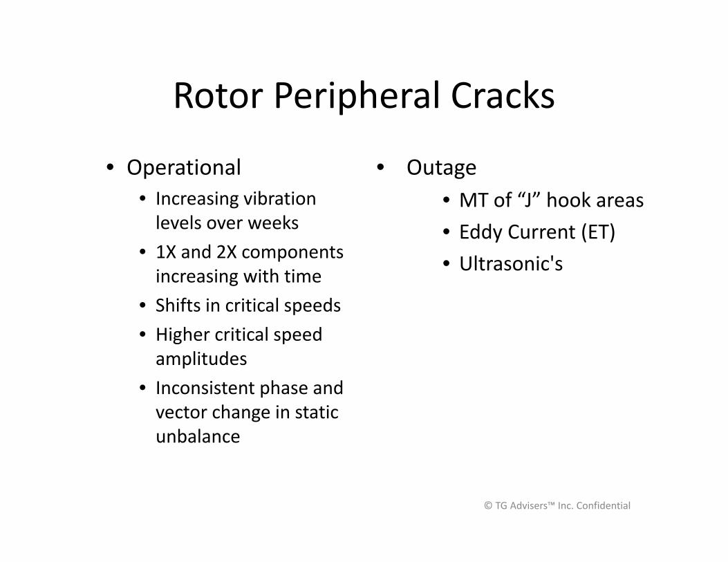
Rotor Peripheral Cracks
• Operational• Increasing vibration
levels over weeks• 1X and 2X components
increasing with time• Shifts in critical speeds• Higher critical speed
amplitudes• Inconsistent phase and
vector change in static unbalance
• Outage• MT of “J” hook areas• Eddy Current (ET)• Ultrasonic's
© TG Advisers™ Inc. Confidential
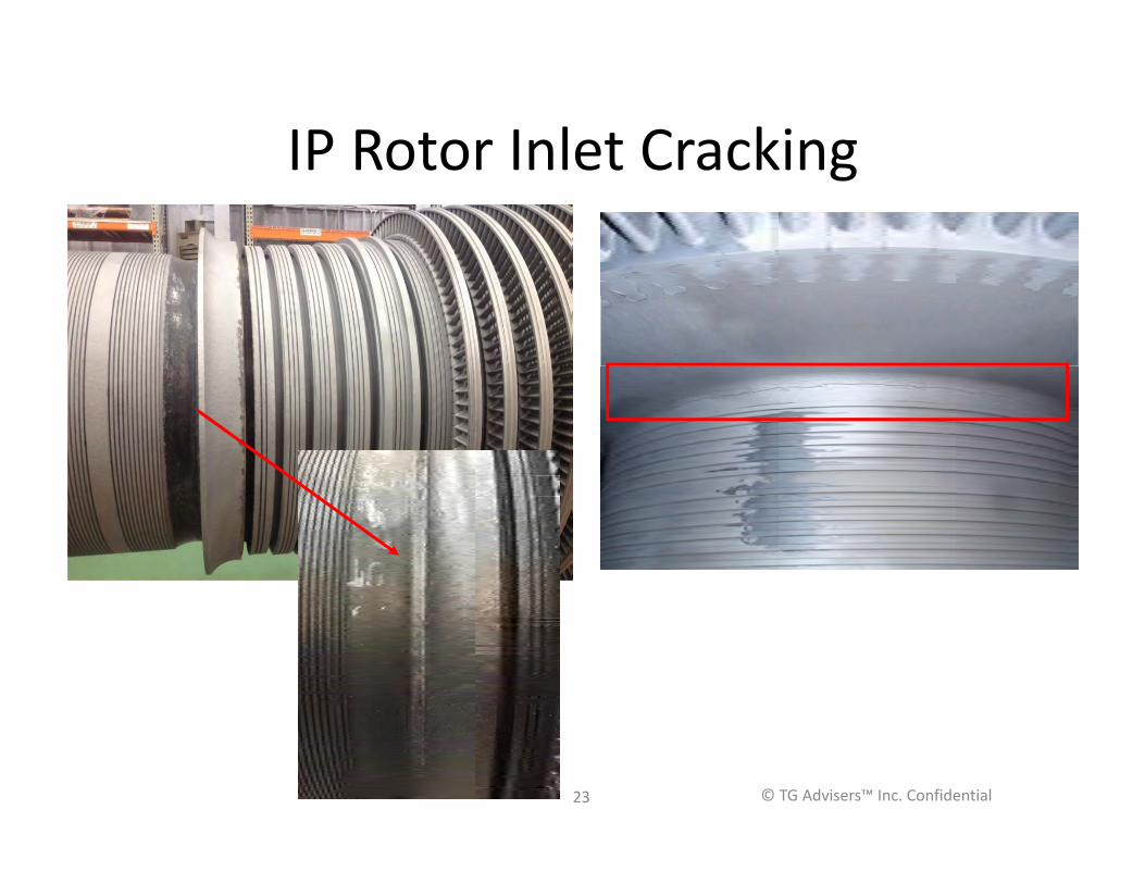
IP Rotor Inlet Cracking
23 © TG Advisers™ Inc. Confidential
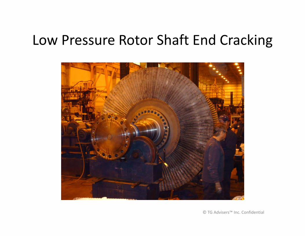
Low Pressure Rotor Shaft End Cracking
© TG Advisers™ Inc. Confidential
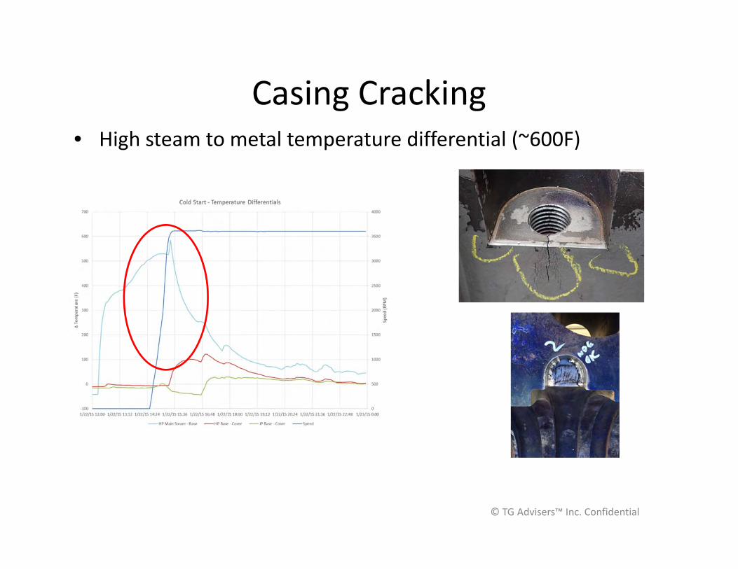
Casing Cracking• High steam to metal temperature differential (~600F)
© TG Advisers™ Inc. Confidential
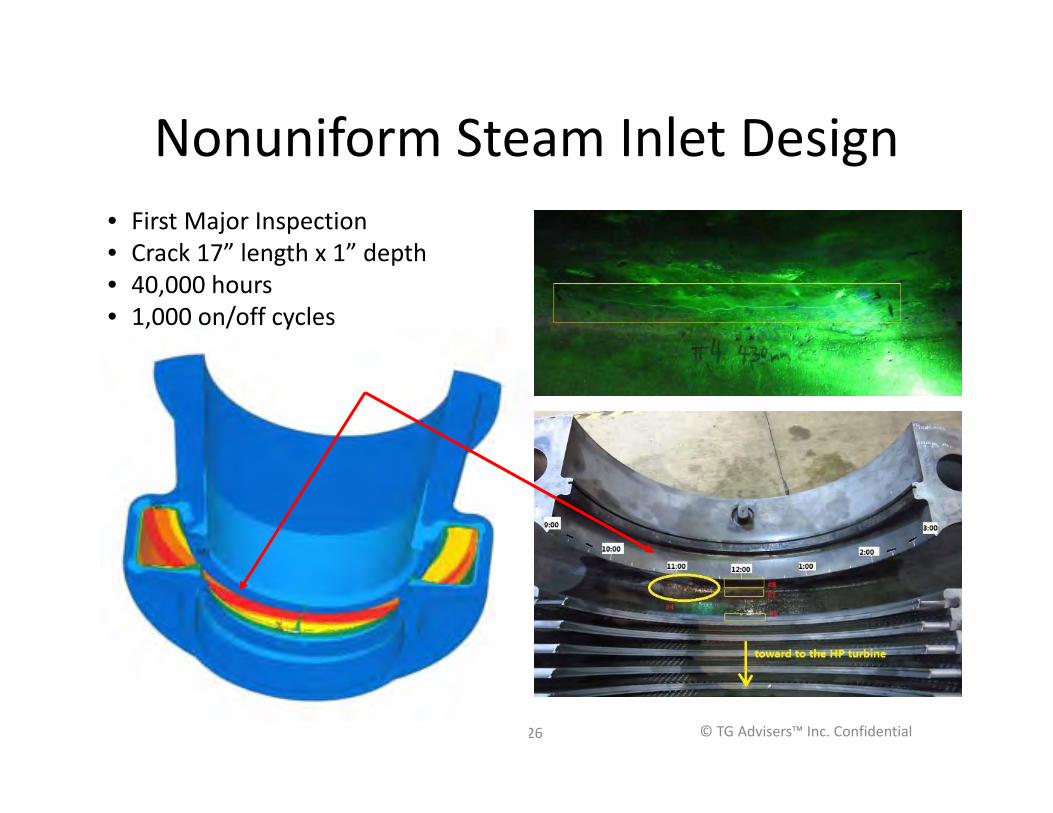
Nonuniform Steam Inlet Design
26
• First Major Inspection• Crack 17” length x 1” depth• 40,000 hours• 1,000 on/off cycles
© TG Advisers™ Inc. Confidential

RUBS – RADIAL AND AXIAL
© TG Advisers™ Inc. Confidential
Clearances
• Trade off between performance and operability for radial clearances
• Set seal clearances appropriate for mode of operation
• Hard seal rubs can lead to blade looseness, rotor bowing, and bearing babbitt fatigue
• Axial clearances must be maintained to avoid differential expansion limitations
© TG Advisers™ Inc. Confidential
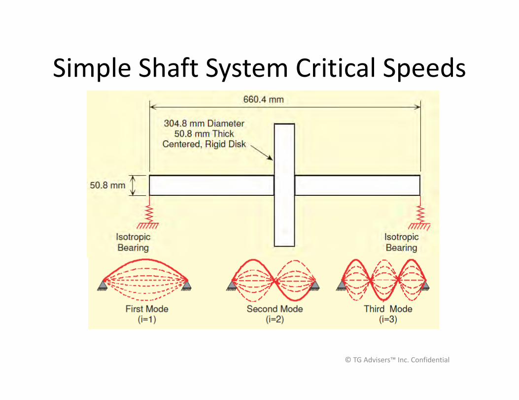
Simple Shaft System Critical Speeds
© TG Advisers™ Inc. Confidential

Integral Shrouded Blades (Looseness)
© TG Advisers™ Inc. Confidential
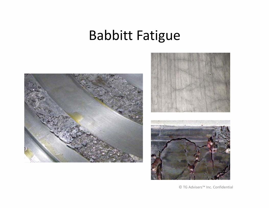
Babbitt Fatigue
© TG Advisers™ Inc. Confidential
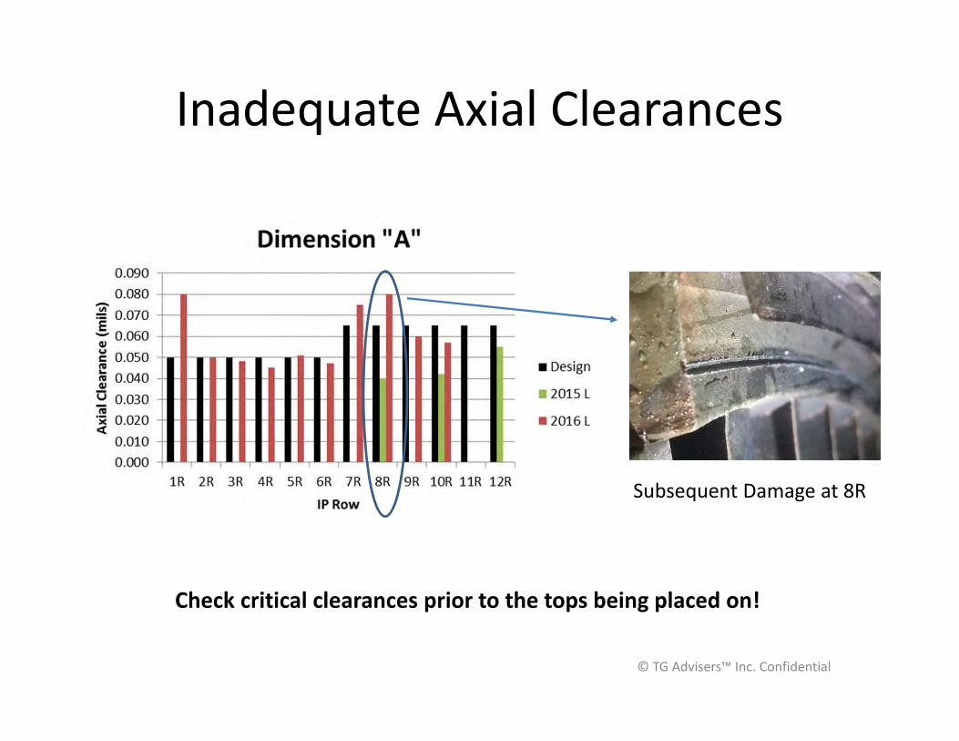
Inadequate Axial Clearances
© TG Advisers™ Inc. Confidential
Subsequent Damage at 8R
Check critical clearances prior to the tops being placed on!
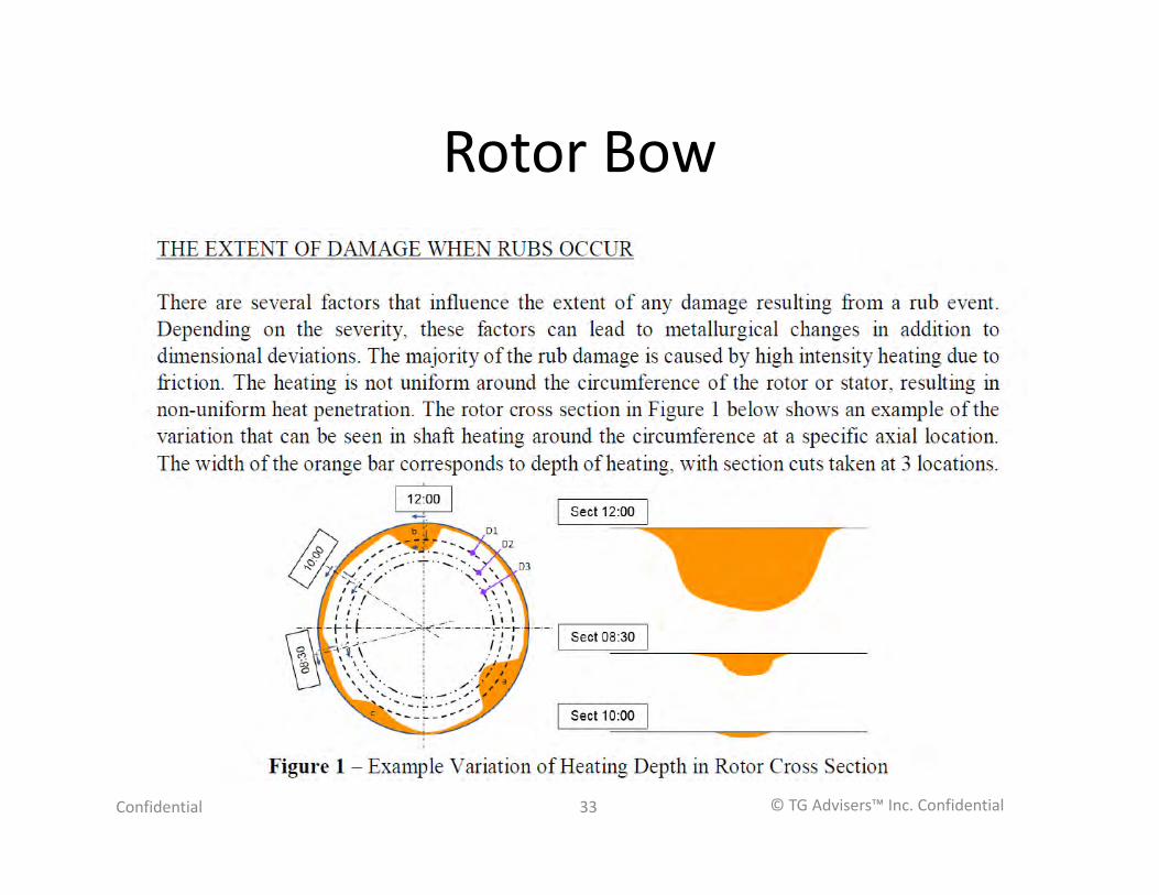
Rotor Bow
Confidential © TG Advisers™ Inc. Confidential33
Rotor Straightening Options
• Hot Spot Rotor diametrically opposite the bow• Machine plastically deformed material at the
bow and weld repair• Re-machine journals and critical rotor
diameters to new centerline• Re-heat treat deformed areas – limited
success
© TG Advisers™ Inc. Confidential
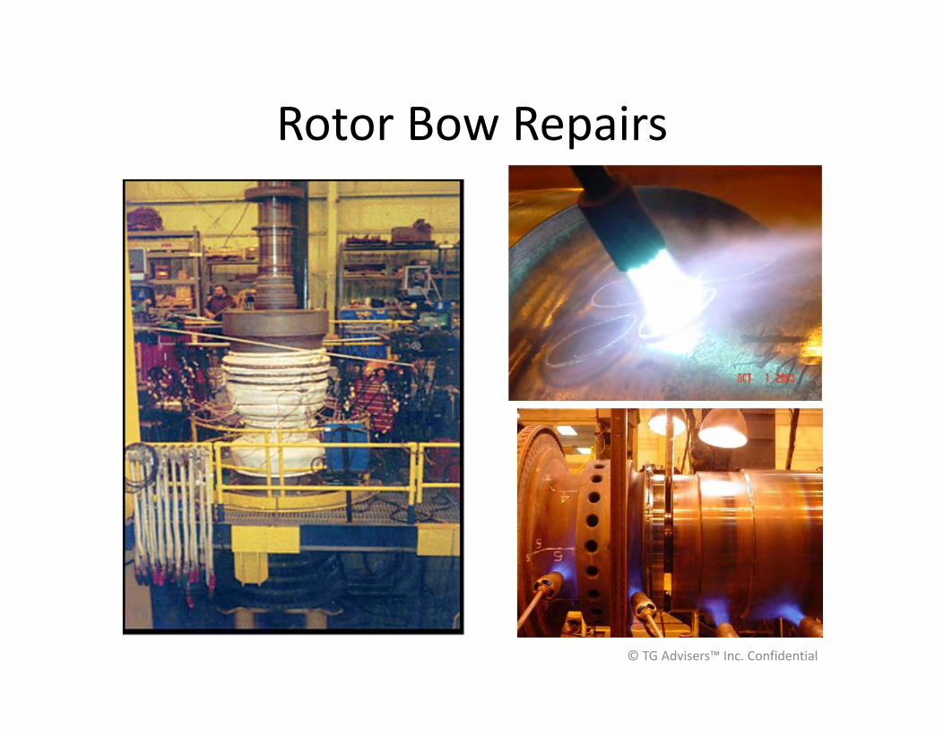
Rotor Bow Repairs
© TG Advisers™ Inc. Confidential
EVENT DRIVEN – WATER INDUCTION, OVERSPEED
© TG Advisers™ Inc. Confidential
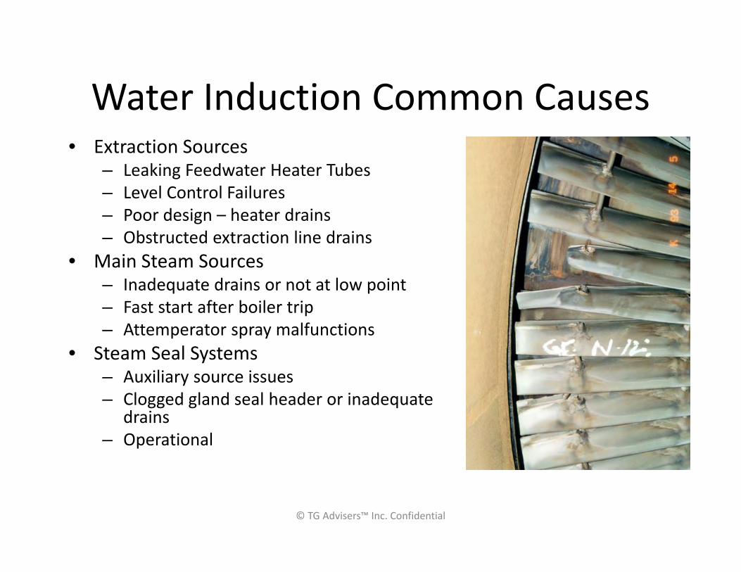
Water Induction Common Causes• Extraction Sources
– Leaking Feedwater Heater Tubes– Level Control Failures– Poor design – heater drains– Obstructed extraction line drains
• Main Steam Sources– Inadequate drains or not at low point– Fast start after boiler trip– Attemperator spray malfunctions
• Steam Seal Systems– Auxiliary source issues– Clogged gland seal header or inadequate
drains– Operational
© TG Advisers™ Inc. Confidential
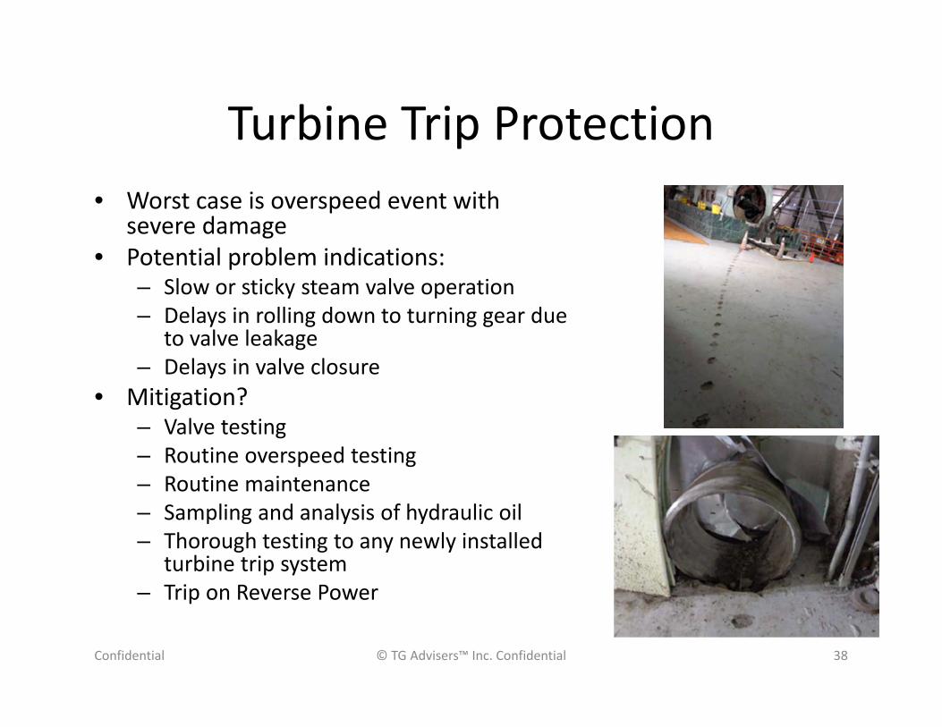
Turbine Trip Protection• Worst case is overspeed event with
severe damage• Potential problem indications:
– Slow or sticky steam valve operation– Delays in rolling down to turning gear due
to valve leakage– Delays in valve closure
• Mitigation?– Valve testing– Routine overspeed testing– Routine maintenance– Sampling and analysis of hydraulic oil– Thorough testing to any newly installed
turbine trip system– Trip on Reverse Power
Confidential © TG Advisers™ Inc. Confidential 38

Thank you – Questions?
Steam Power Plant Cycling Symposium Update
Gary Ruhl Manager, Fuels & Technical Services
Omaha Public Power District
1
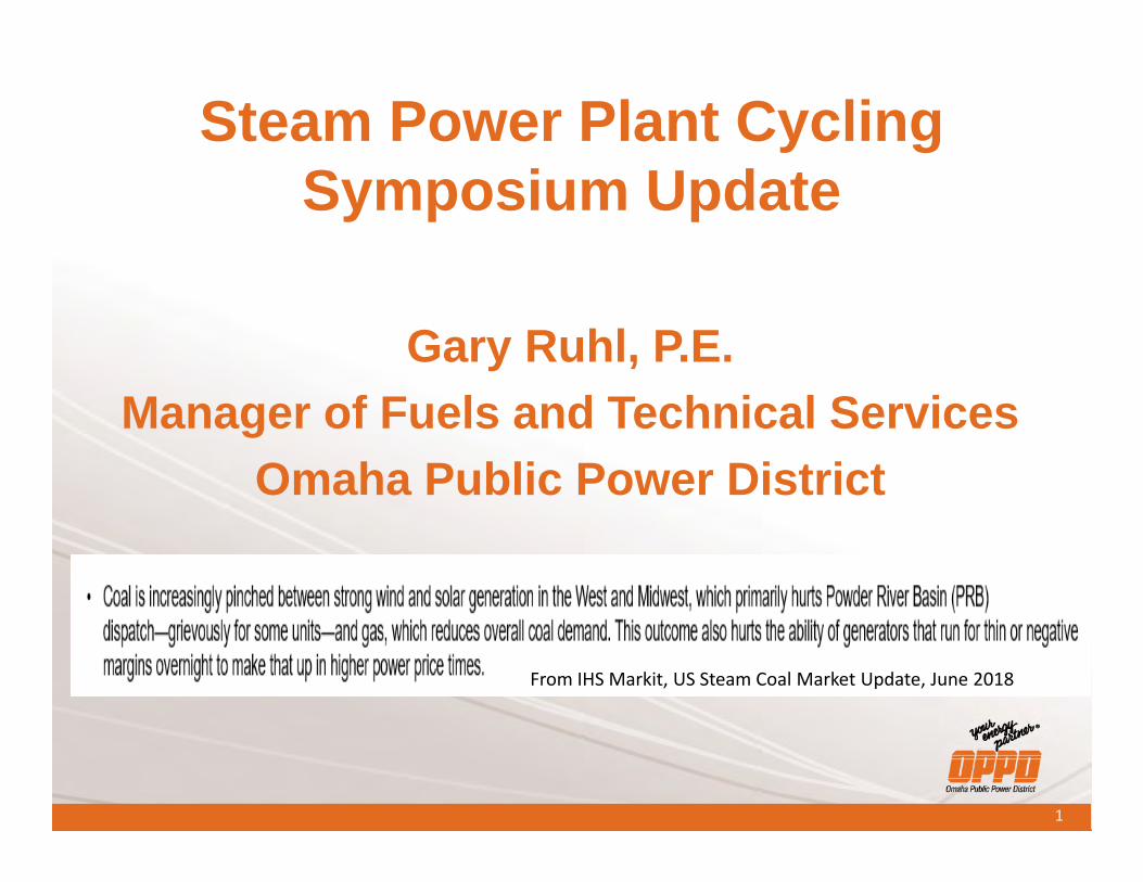
Steam Power Plant Cycling Symposium Update
Gary Ruhl, P.E.Manager of Fuels and Technical Services
Omaha Public Power District
From IHS Markit, US Steam Coal Market Update, June 2018
2
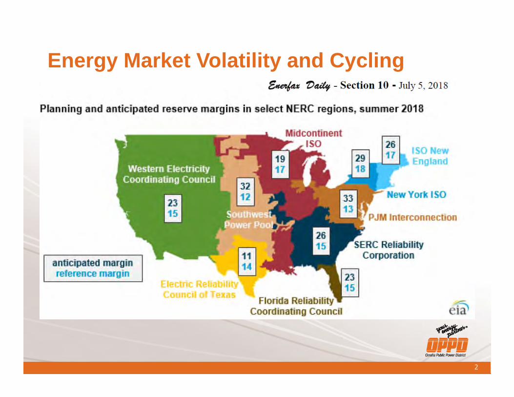
Energy Market Volatility and Cycling
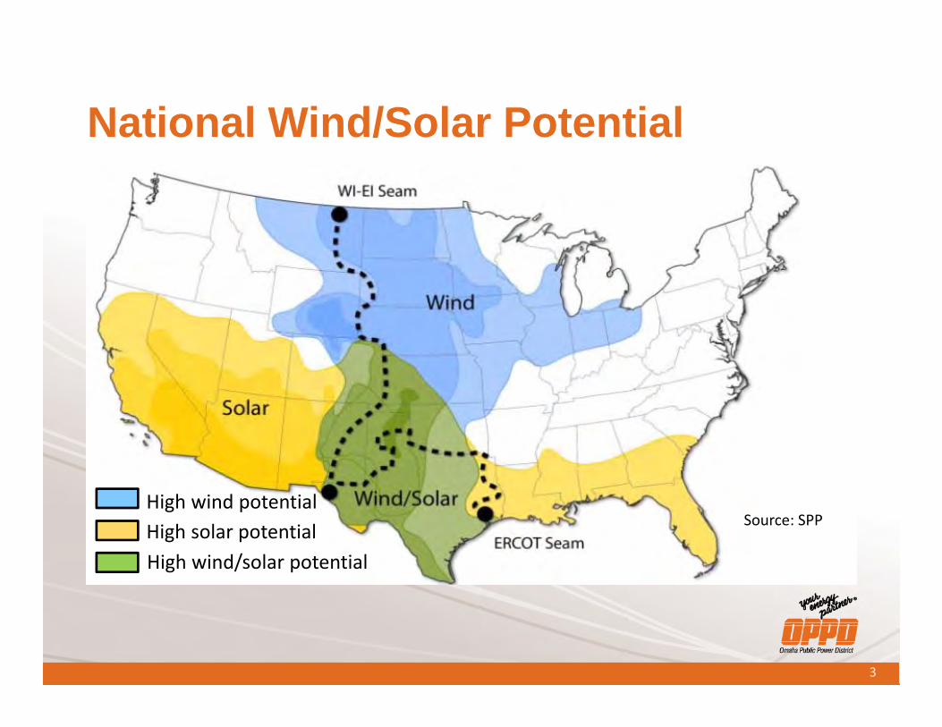
National Wind/Solar Potential
High wind potentialHigh solar potentialHigh wind/solar potential
3
Source: SPP
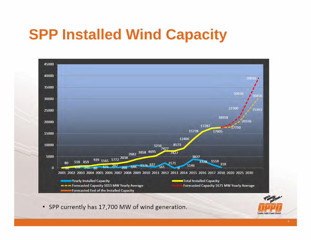
SPP Installed Wind Capacity
4
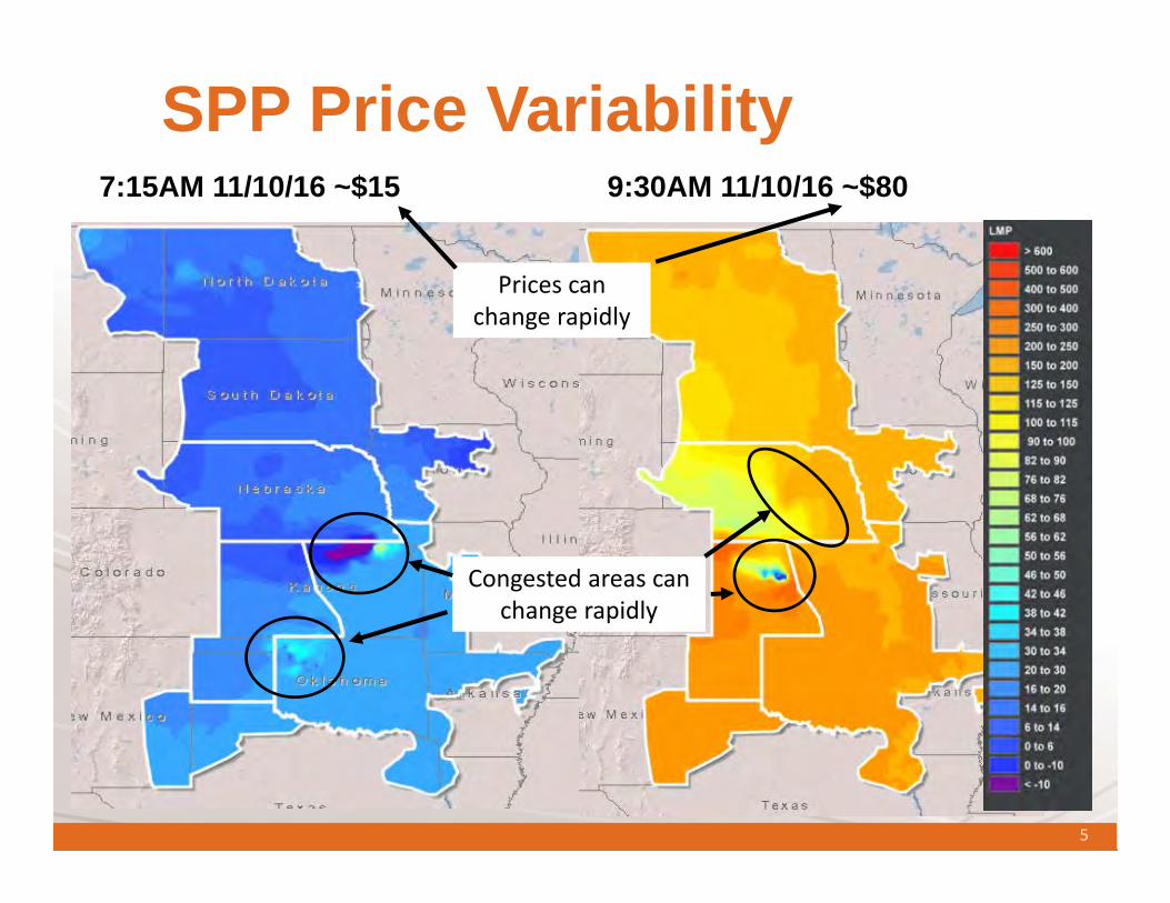
SPP Price Variability7:15AM 11/10/16 ~$15 9:30AM 11/10/16 ~$80
Congested areas can change rapidly
Prices can change rapidly
5
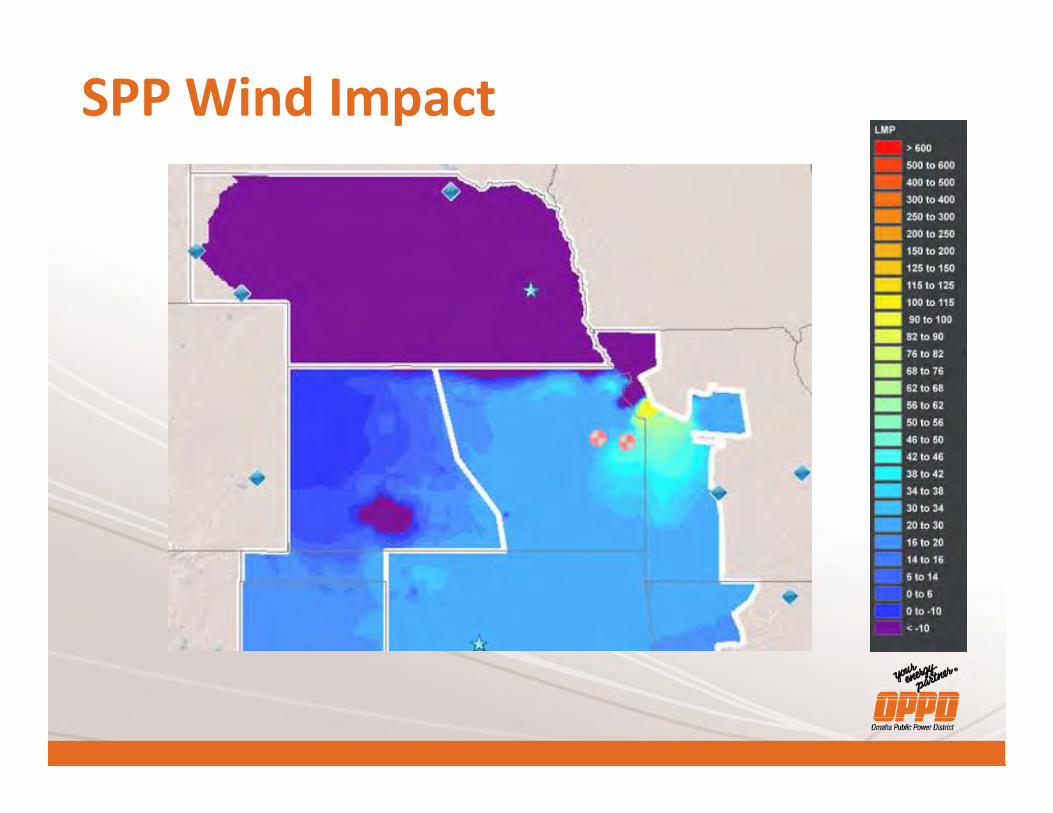
SPP Wind Impact
7
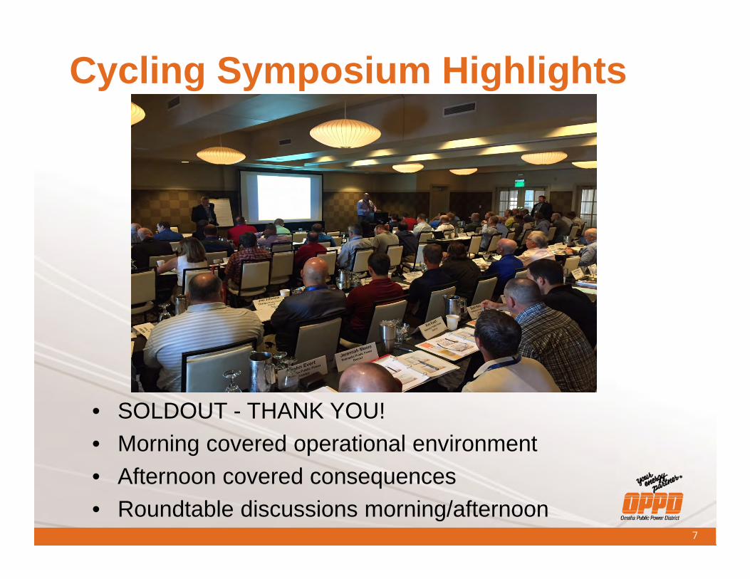
Cycling Symposium Highlights
• SOLDOUT - THANK YOU!• Morning covered operational environment• Afternoon covered consequences• Roundtable discussions morning/afternoon
8
9
10
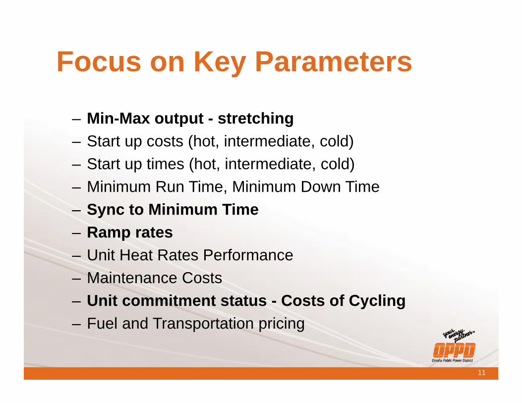
Focus on Key Parameters
– Min-Max output - stretching– Start up costs (hot, intermediate, cold)– Start up times (hot, intermediate, cold)– Minimum Run Time, Minimum Down Time– Sync to Minimum Time– Ramp rates– Unit Heat Rates Performance– Maintenance Costs– Unit commitment status - Costs of Cycling– Fuel and Transportation pricing
11
12
13
14
15
16
17
18
19
20
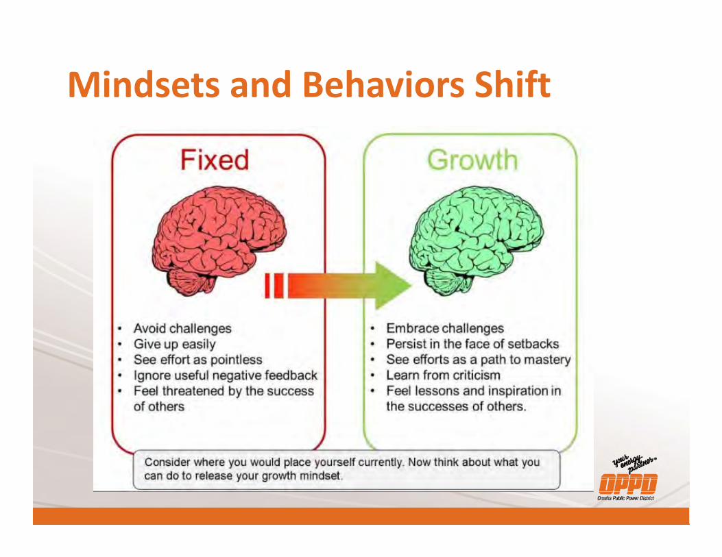
Mindsets and Behaviors Shift

Nelson Mandela
“If you talk to a man in a language he understands, that goes to his head. If you talk to him in his language, that goes to his heart.”
22
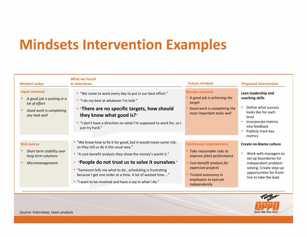
Source: Interviews, team analysis
Mindsets Intervention Examples
Mindset today Future mindset Proposed interventionWhat we heard in interviews
Input oriented
▪ A good job is putting in a lot of effort
▪ Good work is completing any task well
Risk averse
▪ Short term stability over long term solutions
▪ Micromanagement
Results oriented▪ A good job is achieving the
target ▪ Good work is completing the
most important tasks well
Continuous improvement
▪ Take reasonable risks to improve plant performance
▪ Cost-benefit analysis for expensive projects
▪ Trusted autonomy in employees to execute independently
▪ “We come to work every day to put in our best effort.”
▪ “I do my best at whatever I’m told.”
▪ “There are no specific targets, how should they know what good is?”
▪ “I don’t have a direction on what I‘m supposed to work for, so I just try hard.”
▪ “We know how to fix it for good, but it would mean some risk, so they tell us do it the usual way.”
▪ “A cost-benefit analysis they show the money’s worth it.”
▪ “People do not trust us to solve it ourselves.”
▪ “Someone tells me what to do…scheduling is frustrating because I get one order at a time. A lot of wasted time …”
▪ “I want to be involved and have a say in what I do.”
Lean leadership and coaching skills
Define what success looks like for each level
Incorporate metrics into feedback
Publicly track key metrics
Create no-blame culture
▪ Work with managers to set up boundaries for independent problem-solving. Create step-up opportunities for front-line to take the lead.
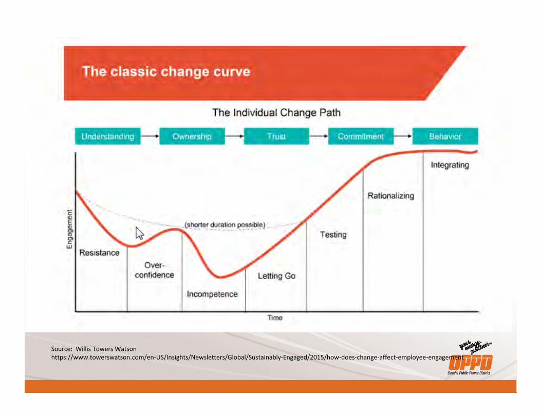
Source: Willis Towers Watsonhttps://www.towerswatson.com/en-US/Insights/Newsletters/Global/Sustainably-Engaged/2015/how-does-change-affect-employee-engagement

Answering the Whys….• Learning Series
– We began to teach about why the units were cycling more.
• Energy Marketing• Renewables• Integrated Resource Plan
• Leadership Communication - Targets• IGS and PSS Training
Morning Roundtable

Afternoon Roundtable
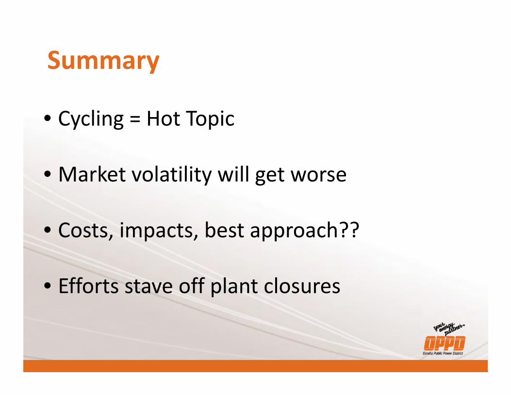
Summary
• Cycling = Hot Topic
• Market volatility will get worse
• Costs, impacts, best approach??
• Efforts stave off plant closures
Low Impact Generation CIP Compliance
Ryan Walter Compliance Analyst
Tri-State Generation & Transmission Association
Low Impact Generation CIP Compliance
Ryan Walter
2
Agenda
Entity Overview NERC CIP Introduction CIP-002-5.1, Asset Classification What Should Already be Done CIP-003-7, Low Impact Requirements Tri-State’s Approach Removable Media and Transient Cyber Assets
3
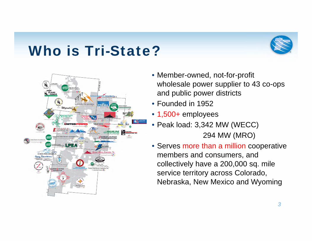
Who is Tri-State?• Member-owned, not-for-profit
wholesale power supplier to 43 co-ops and public power districts
• Founded in 1952• 1,500+ employees• Peak load: 3,342 MW (WECC)
294 MW (MRO)• Serves more than a million cooperative
members and consumers, and collectively have a 200,000 sq. mile service territory across Colorado, Nebraska, New Mexico and Wyoming
4
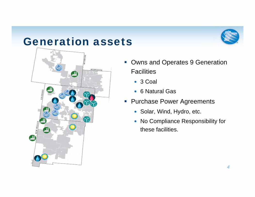
Generation assets
Owns and Operates 9 Generation Facilities 3 Coal 6 Natural Gas
Purchase Power Agreements Solar, Wind, Hydro, etc. No Compliance Responsibility for
these facilities.
5
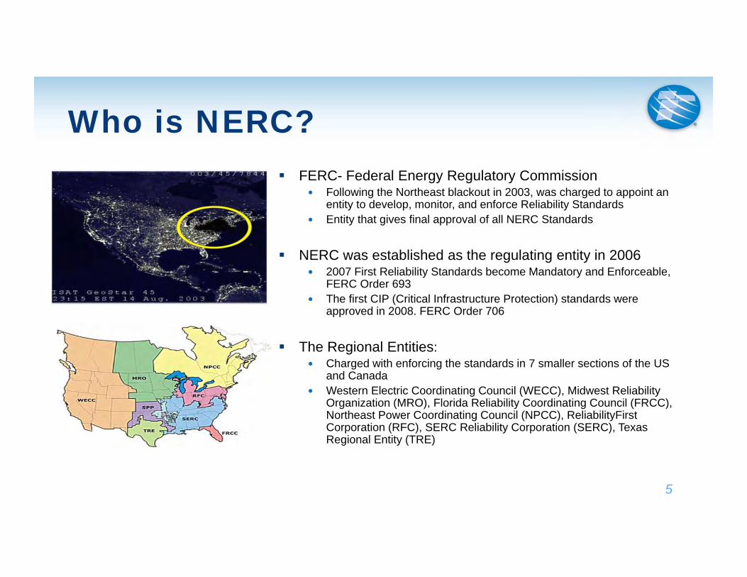
Who is NERC? FERC- Federal Energy Regulatory Commission
Following the Northeast blackout in 2003, was charged to appoint an entity to develop, monitor, and enforce Reliability Standards
Entity that gives final approval of all NERC Standards
NERC was established as the regulating entity in 2006 2007 First Reliability Standards become Mandatory and Enforceable,
FERC Order 693 The first CIP (Critical Infrastructure Protection) standards were
approved in 2008. FERC Order 706
The Regional Entities: Charged with enforcing the standards in 7 smaller sections of the US
and Canada Western Electric Coordinating Council (WECC), Midwest Reliability
Organization (MRO), Florida Reliability Coordinating Council (FRCC), Northeast Power Coordinating Council (NPCC), ReliabilityFirstCorporation (RFC), SERC Reliability Corporation (SERC), Texas Regional Entity (TRE)
What is CIP?
6
Standards are primarily directed towards Cyber Security, but also includes Physical Security
Current version of the CIP Standards went into effect in 2016 This version established High, Medium,
Low asset rating criteria
Upcoming Standards and Requirements Supply Chain Management Low Impact Transient Cyber Assets and
Removable Media Requirements Also in development: Virtualization and
cloud storage, computing, etc.
CIP-002-5.1 for Generation –Plant Impact Rating Medium Impact Rating for Plant
1500 MW Net Real Power Capability in a single interconnection for a single unit or group of units
Generation Station that the Reliability Coordinator, Planning Coordinator, or Transmission Planner deem critical to the BES
Only cyber assets or systems that could within 15 minutes adversely impact the reliable operation of the plant are subject to the CIP Standards
Potential assets and systems: DCS devices, Microprocessor Relays, RTU’s, etc.
Low Impact Rating for Plants All BES Generating Stations/Units not included in the Medium Criteria Only cyber assets that could within 15 minutes adversely impact the reliable
operation of the plant are subject to the Low Impact Requirements
7
CIP-002-5.1 Tri-State’s Methodology
Step 1: Evaluate all systems at our BES plants to determine if they could impact operations or availability of the plant within 15 minutes Examples: DCS, Chiller System, Vibration Monitoring, CEMS, etc.
Step 2: For systems identified in Step 2, label as a BES Cyber System, and inventory all associated Cyber Assets. Potential assets: DCS Servers, Microprocessor Relays, Battery Chargers,
RTU’s, switches, PLCs, Operator Consoles, Chiller Controllers, etc.
Step 3: Identify all routable and dialup connectivity
Step 4: Document and have CIP Senior Manager approve a list of Assets with one or more BES Cyber Systems Annually verify your list is still correct.
8
9
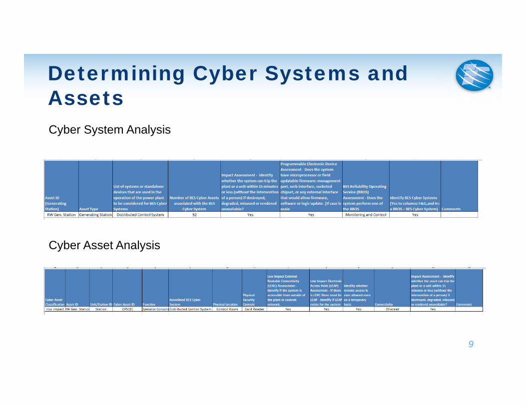
Determining Cyber Systems and AssetsCyber System Analysis
Cyber Asset Analysis
What should already be done
All entities with Low Impact assets had to write a Cyber Security Plan for Physical and Electronic Security Controls, Cyber Security Awareness and Cyber Security Incident Response by 04/01/17.
Entities had to reinforce cyber security awareness at all low facilities by 04/01/17 and every 15 months thereafter
All entities with Low Impact assets had to write and test their Cyber Security Incident response plan by 04/01/17.
Document all of your compliance efforts.
10
CIP-003-7 for Low Impact
Cyber Security Awareness (April 1, 2017) Every 15 Months you must reinforce cyber security practices (example: training, poster
changes, etc.)
Physical Security Controls (January 1, 2020, Originally July 1, 2018) Control physical access to the plant itself or the locations where BES Cyber Systems
(BCS) reside, and The Cyber Assets that provide electronic access controls below
Electronic Access Controls (January 1, 2020, Originally July 1, 2018) Should only permit necessary inbound and outbound electronic access for
communications that are: Between a Low Impact BCS at the plant and a Cyber Asset outside the plant Using routable protocol when entering or leaving the plant Not used for time-sensitive protection or controls functions
Authenticate all Dial-up Connectivity
11
CIP-003-7 Continued
Cyber Security Incident Response (April 1, 2017) Entities must create and test a plan to Identify, Classify and respond to Cyber Security
IncidentsThe New Ones: Transient Cyber Asset Malicious code Mitigation (January 1, 2020)
Transient Cyber Asset (TCA) - is an asset that is capable of transmitting or transferring code and is connected to the station’s network or BES Cyber Assets for 30 days or less.
Ex: Company Laptops, Vendor Laptops, or testing devices
Entity owned TCAs must have at least one of the following: antivirus, application whitelisting or other methods to prevent the introduction of malicious code to the network.
3rd Party TCAs- must perform a review of vendor’s methods for malicious code mitigation* Removable Media (January 1, 2020)
Storage devices capable of transferring executable code and is connected to the station’s network or BES Cyber Assets for 30 days or less
Ex: USB Flash Drives, External Hard Drives, CD’s, etc.
Method to detect Malicious Code on Removable Media, and Mitigating any Malicious Code found on that Removable Media prior to use.
12
Tri-State’s Implementation Details
13
Cyber Security Awareness posters or media at all Low impact sites.
Determined a list of BES Cyber Systems
Walkthroughs of all of our generating facilities One walkthrough was to examine
Physical Security Second walkthrough was to gather a
list of all Cyber Assets and all external routable connections to the plants.
Once we had our cyber asset list, assets were put into different BES Cyber Systems and given an impact assessment.
14
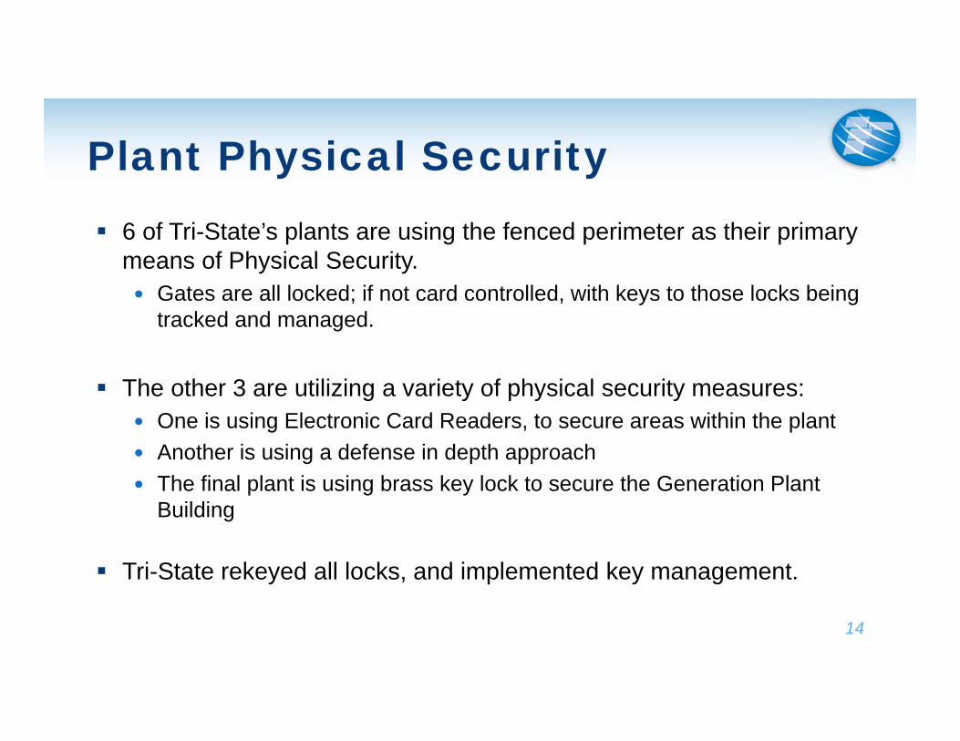
Plant Physical Security 6 of Tri-State’s plants are using the fenced perimeter as their primary
means of Physical Security. Gates are all locked; if not card controlled, with keys to those locks being
tracked and managed.
The other 3 are utilizing a variety of physical security measures: One is using Electronic Card Readers, to secure areas within the plant Another is using a defense in depth approach The final plant is using brass key lock to secure the Generation Plant
Building
Tri-State rekeyed all locks, and implemented key management.
15
Electronic Security All Stations have 2 separate networks. The plant network (where the
DCS resides) and the corporate network.
The networks are segregated by an IT managed firewall. Does not have to be a firewall, could be a switch, Communication
Processor, etc. as long as you can control or “manage” inbound and outbound traffic.
16
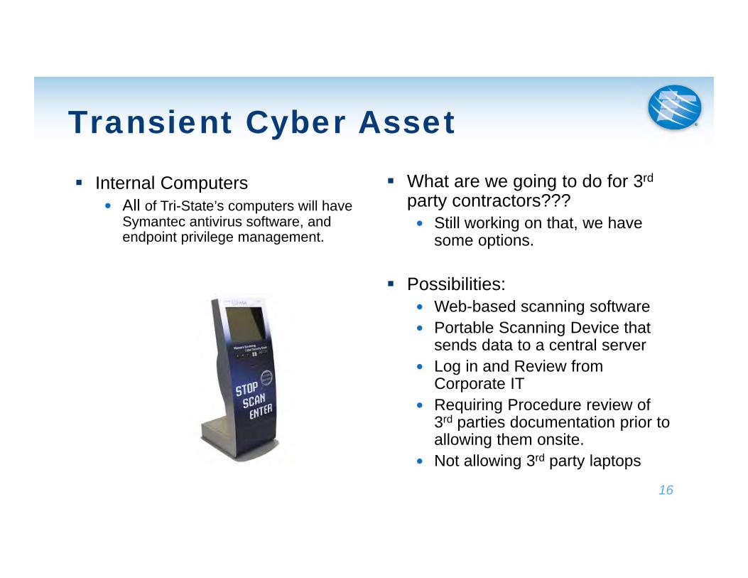
Transient Cyber Asset Internal Computers
All of Tri-State’s computers will have Symantec antivirus software, and endpoint privilege management.
What are we going to do for 3rd
party contractors??? Still working on that, we have
some options.
Possibilities: Web-based scanning software Portable Scanning Device that
sends data to a central server Log in and Review from
Corporate IT Requiring Procedure review of
3rd parties documentation prior to allowing them onsite.
Not allowing 3rd party laptops
17
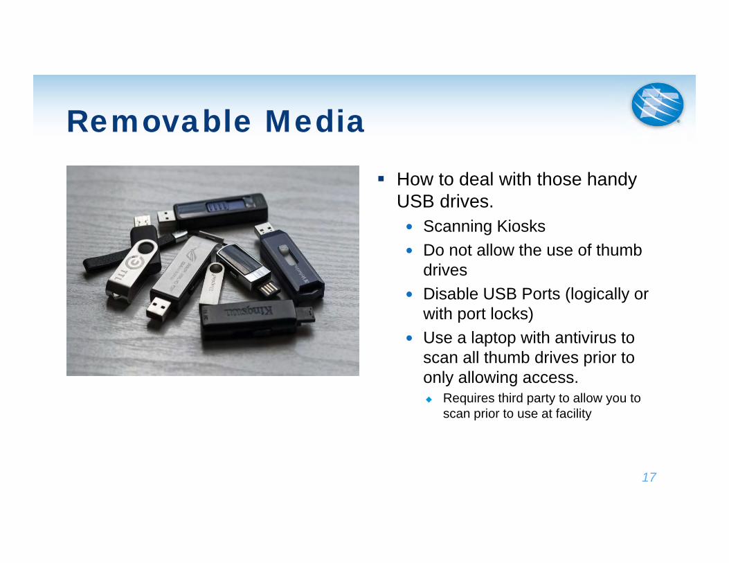
Removable Media How to deal with those handy
USB drives. Scanning Kiosks Do not allow the use of thumb
drives Disable USB Ports (logically or
with port locks) Use a laptop with antivirus to
scan all thumb drives prior to only allowing access. Requires third party to allow you to
scan prior to use at facility
18
Takeaways
Don’t procrastinate Will help you work out the issues before you
have to be compliant
Document your Efforts
Work with your vendors Make sure your strategies will work with your
systems and won’t hinder plant operations.


Physical Security (Suspicious Package Handling)
Thomas Livingston Plant Manager, Four Corners Power Plant
Arizona Public Service
Four Corners Power Plant
Suspicious Device Discussion
August 1st, 2018
2
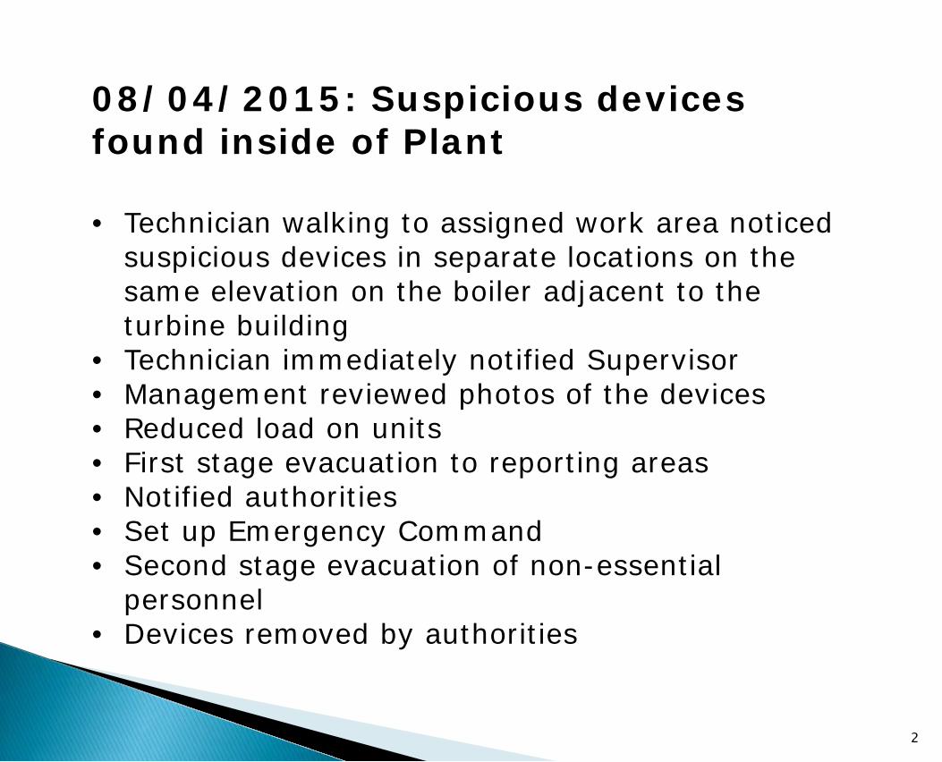
08/04/2015: Suspicious devices found inside of Plant • Technician walking to assigned work area noticed
suspicious devices in separate locations on the same elevation on the boiler adjacent to the turbine building
• Technician immediately notified Supervisor • Management reviewed photos of the devices • Reduced load on units • First stage evacuation to reporting areas • Notified authorities • Set up Emergency Command • Second stage evacuation of non-essential
personnel • Devices removed by authorities
Evacuation
Communication
Emergency Command
Control Situation
3
Preparation
Food & Water Available
Notification
Work Area Inspections
Media
4
Drills Command Center Readiness Notification Area Control EAPs Local, State, and Federal Officials Familiar Emergency Assignments Food & Water Media
5
NERC BAL-003 – Frequency Response Impacts on Plants
Bill Paiz Power Production Engineer V
PNM Resources
Saul Macias Power Production Engineer
PNM Resources
NERC BAL 003-1.1IMPACT ON POWER PLANTSRMEL, August 2, 2018
– Purpose – Grid Stability – Generator Governor
Frequency Response for Generators Outline
• To provide sufficient Frequency Response from the plants within predefined bounds by arresting frequency deviations and supporting frequency until the frequency is restored to its scheduled value.
Frequency Response for Generators Purpose
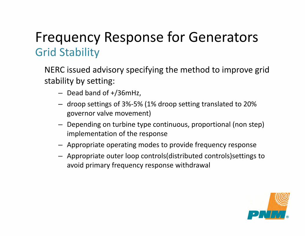
Frequency Response for Generators Grid Stability
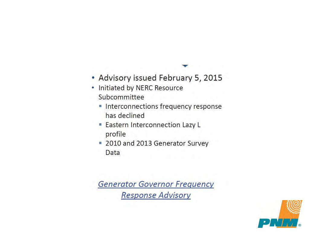
NERC issued advisory specifying the method to improve grid stability by setting:
– Dead band of +/36mHz,– droop settings of 3%-5% (1% droop setting translated to 20%
governor valve movement) – Depending on turbine type continuous, proportional (non step)
implementation of the response– Appropriate operating modes to provide frequency response– Appropriate outer loop controls(distributed controls)settings to
avoid primary frequency response withdrawal
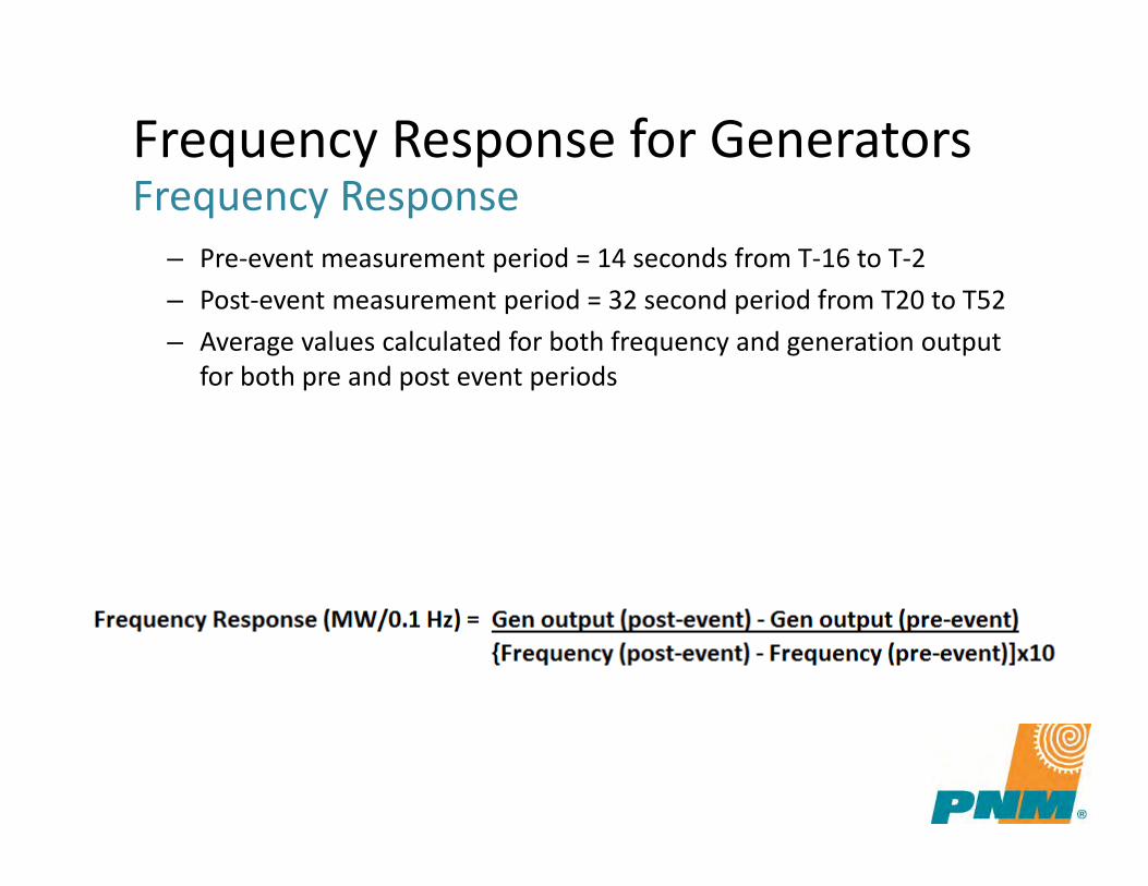
– Pre-event measurement period = 14 seconds from T-16 to T-2 – Post-event measurement period = 32 second period from T20 to T52 – Average values calculated for both frequency and generation output
for both pre and post event periods
Frequency Response for Generators Frequency Response
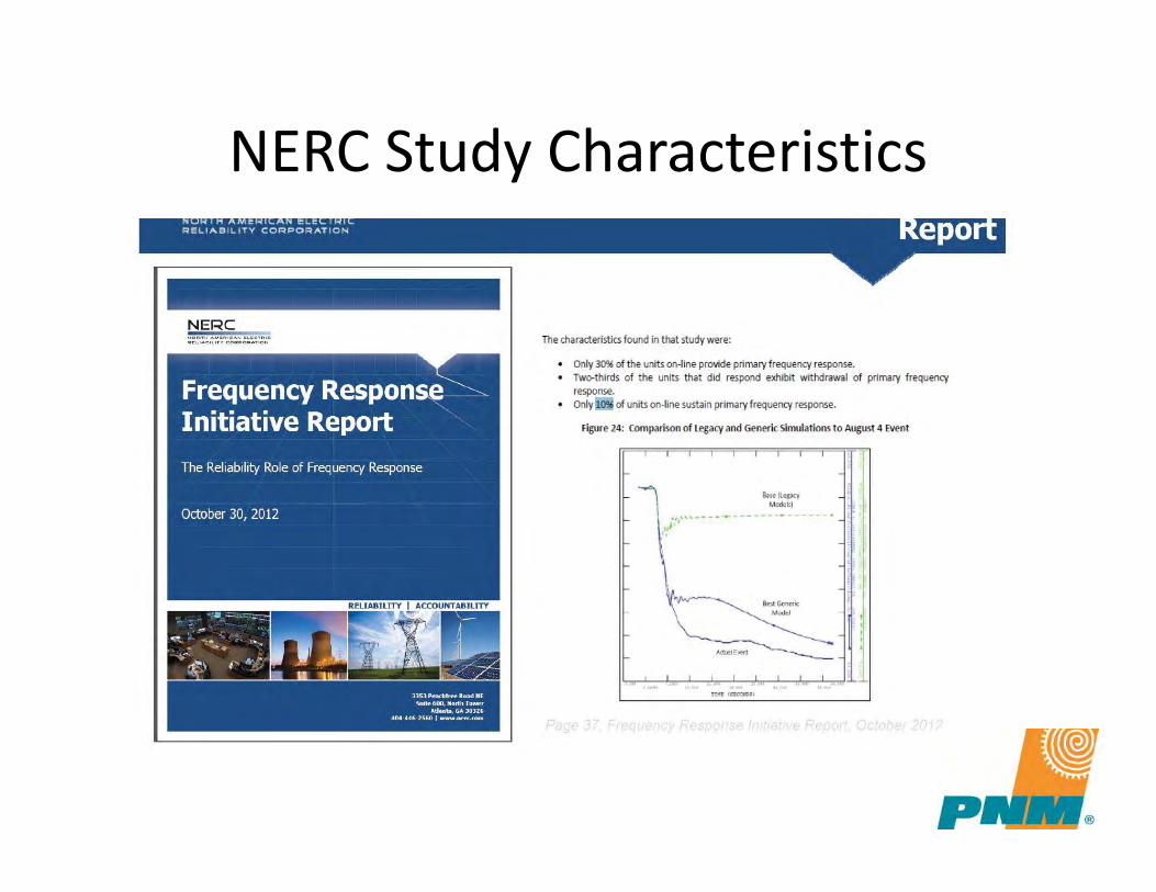
NERC Study Characteristics
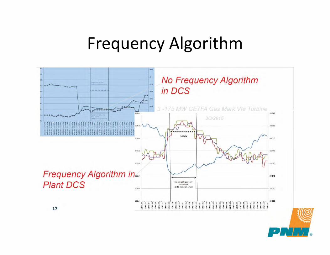
Frequency Algorithm
2016-17 Compliance Year
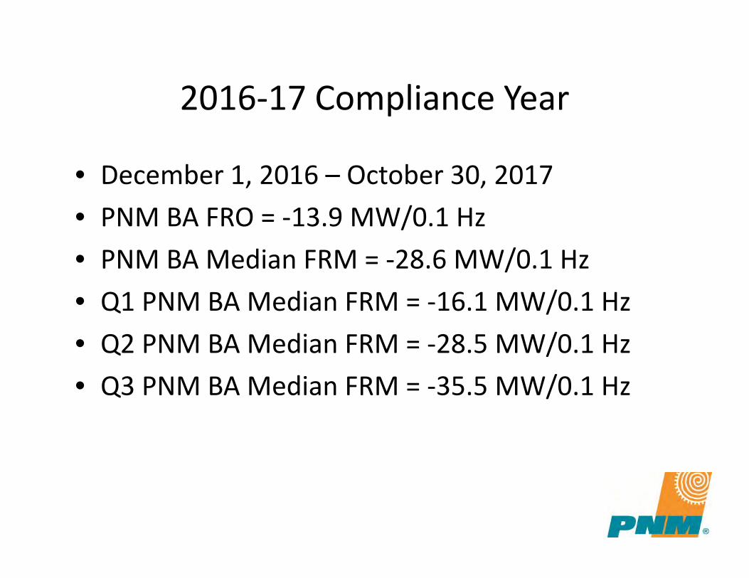
• December 1, 2016 – October 30, 2017• PNM BA FRO = -13.9 MW/0.1 Hz• PNM BA Median FRM = -28.6 MW/0.1 Hz• Q1 PNM BA Median FRM = -16.1 MW/0.1 Hz• Q2 PNM BA Median FRM = -28.5 MW/0.1 Hz• Q3 PNM BA Median FRM = -35.5 MW/0.1 Hz
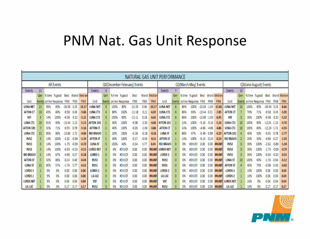
PNM Nat. Gas Unit Response
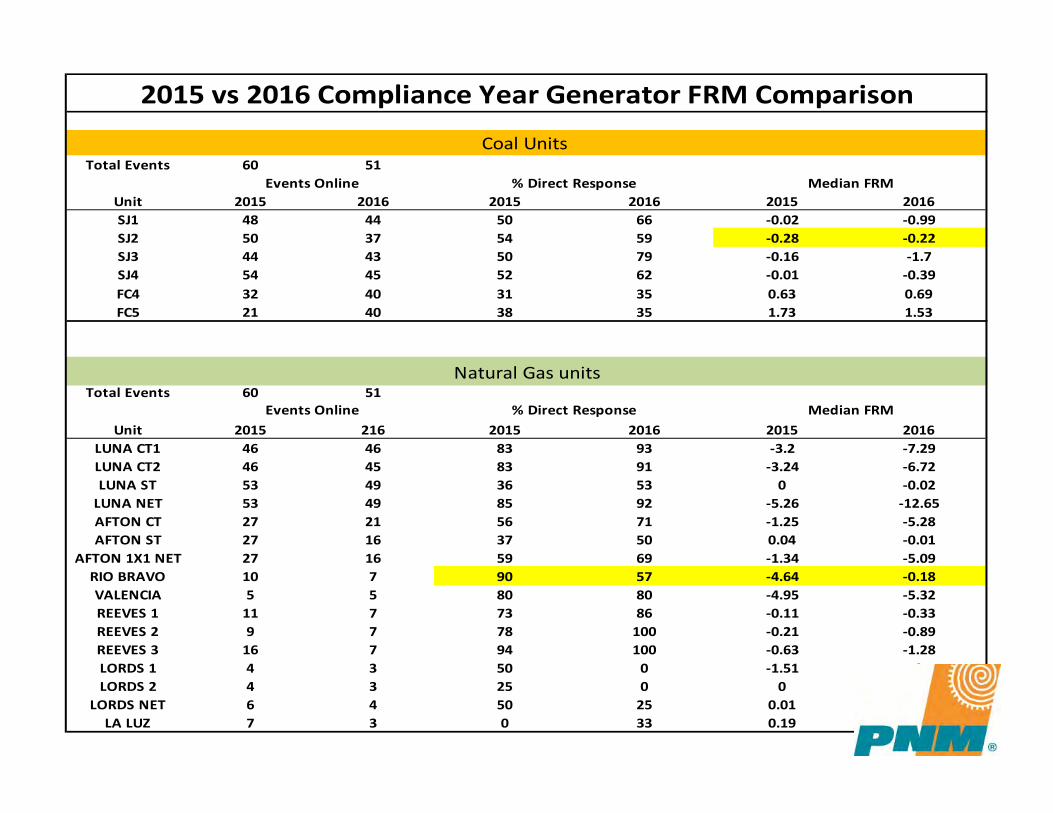
Total Events 60 51
Unit 2015 2016 2015 2016 2015 2016SJ1 48 44 50 66 -0.02 -0.99SJ2 50 37 54 59 -0.28 -0.22SJ3 44 43 50 79 -0.16 -1.7SJ4 54 45 52 62 -0.01 -0.39FC4 32 40 31 35 0.63 0.69FC5 21 40 38 35 1.73 1.53
Total Events 60 51
Unit 2015 216 2015 2016 2015 2016LUNA CT1 46 46 83 93 -3.2 -7.29LUNA CT2 46 45 83 91 -3.24 -6.72LUNA ST 53 49 36 53 0 -0.02
LUNA NET 53 49 85 92 -5.26 -12.65AFTON CT 27 21 56 71 -1.25 -5.28AFTON ST 27 16 37 50 0.04 -0.01
AFTON 1X1 NET 27 16 59 69 -1.34 -5.09RIO BRAVO 10 7 90 57 -4.64 -0.18VALENCIA 5 5 80 80 -4.95 -5.32REEVES 1 11 7 73 86 -0.11 -0.33REEVES 2 9 7 78 100 -0.21 -0.89REEVES 3 16 7 94 100 -0.63 -1.28LORDS 1 4 3 50 0 -1.51 0LORDS 2 4 3 25 0 0 0
LORDS NET 6 4 50 25 0.01 0.05LA LUZ 7 3 0 33 0.19 0.17
Events Online % Direct Response Median FRM
2015 vs 2016 Compliance Year Generator FRM Comparison
Natural Gas units
Coal Units
Events Online % Direct Response Median FRM
BW230 Converter
• PNM contracted a 3rd party to implement control system improvements to allow the converter to provide bi-directional frequency response
• Completion of work posted on OASIS 8/18/17• Appears to provide 15 MWs of response regardless of
level of frequency decay and holds response for 2+ min• FRM will vary from -15 MWs/.1 Hz for 100 mHz event to -
30 MWs/.1 Hz for 50 mHz event
Plant Control System Frequency ISSUES
• Reeves – During a frequency excursion unit’s did not sustain
support.– Frequency response dead band too large
• Rio Bravo( Combustion Turbine)– During a frequency excursion unit’s did not sustain
support.– Frequency response dead band too large– Emission's Issues
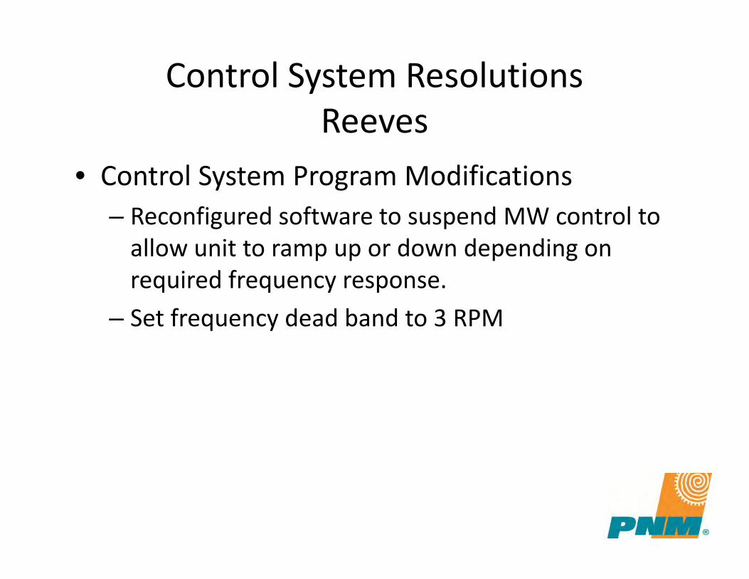
Control System ResolutionsReeves
• Control System Program Modifications– Reconfigured software to suspend MW control to
allow unit to ramp up or down depending on required frequency response.
– Set frequency dead band to 3 RPM
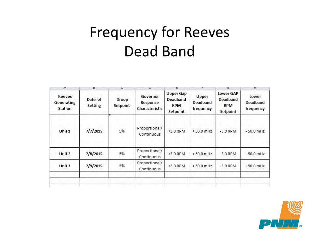
Frequency for ReevesDead Band
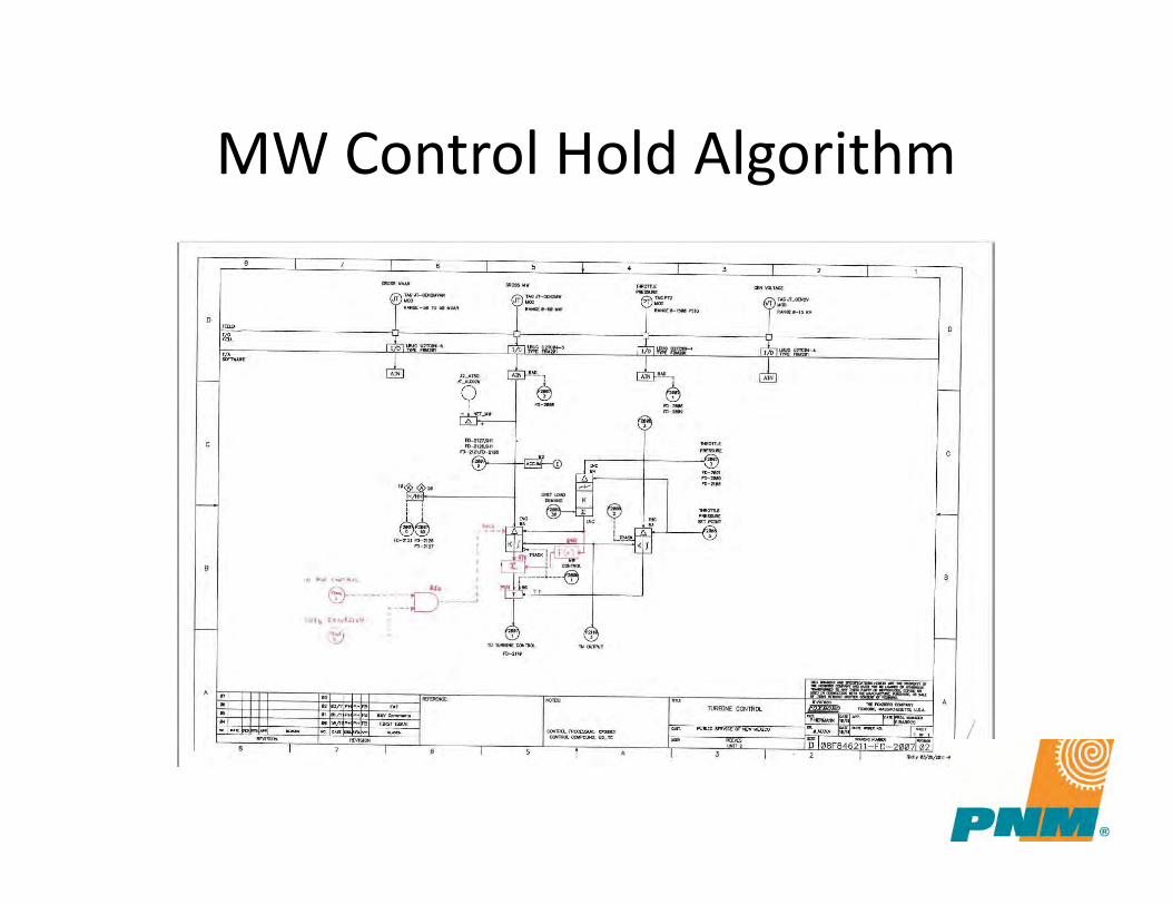
MW Control Hold Algorithm
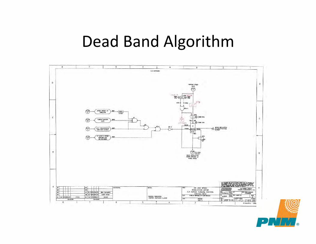
Dead Band Algorithm
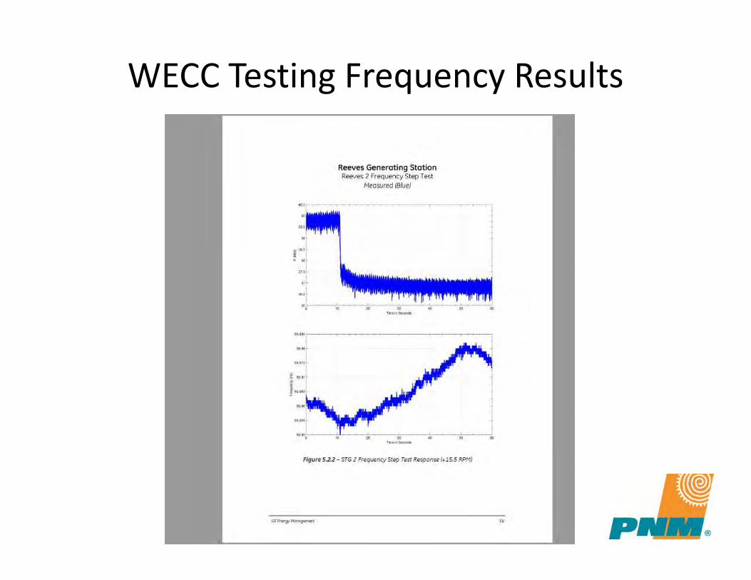
WECC Testing Frequency Results
Control Resolution For Rio Bravo
• Control System Program Modifications– Reconfigured software to suspend MW control to
allow unit to ramp up or down depending on required frequency response.
– Set frequency dead band to 3 RPM.– Limited frequency excursions response to Mode 6
to minimize emissions.
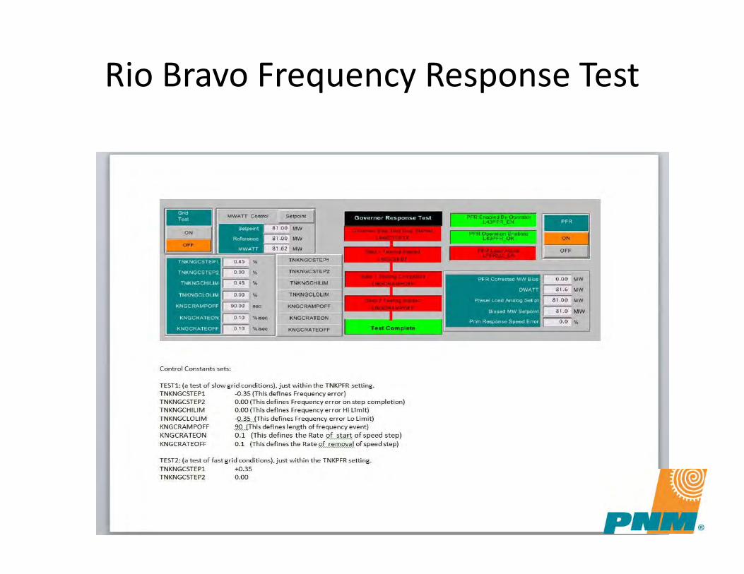
Rio Bravo Frequency Response Test
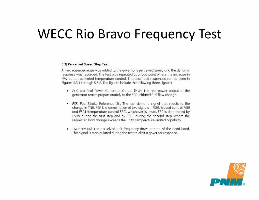
WECC Rio Bravo Frequency Test

Rio Bravo Speed Up Test

Rio Bravo Speed Down Test

Questions?
Thanks!
Four Corners Plant Overview
Thomas Livingston Plant Manager, Four Corners Plant
Arizona Public Service

Four Corners Power Plant
Plant Overview
August 1st, 2018
Asset Overview
2
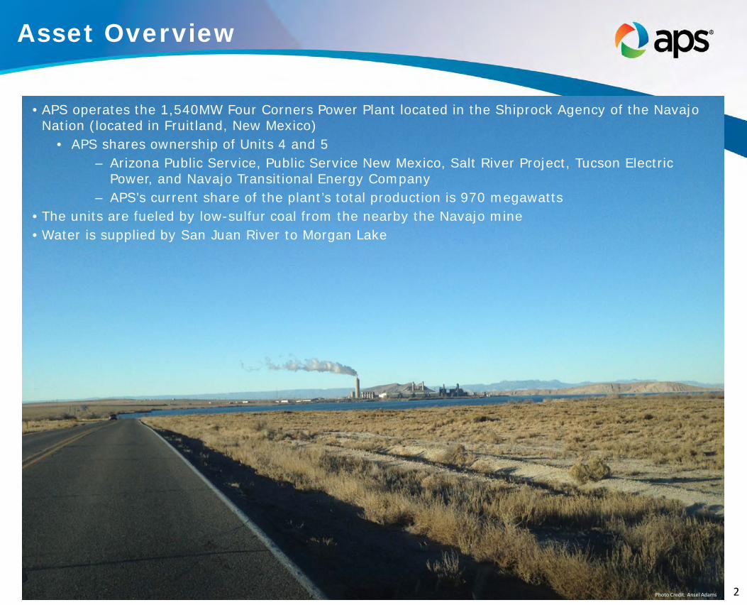
• APS operates the 1,540MW Four Corners Power Plant located in the Shiprock Agency of the Navajo Nation (located in Fruitland, New Mexico)
• APS shares ownership of Units 4 and 5 – Arizona Public Service, Public Service New Mexico, Salt River Project, Tucson Electric
Power, and Navajo Transitional Energy Company – APS’s current share of the plant’s total production is 970 megawatts
• The units are fueled by low-sulfur coal from the nearby the Navajo mine • Water is supplied by San Juan River to Morgan Lake
Photo Credit: Ansel Adams
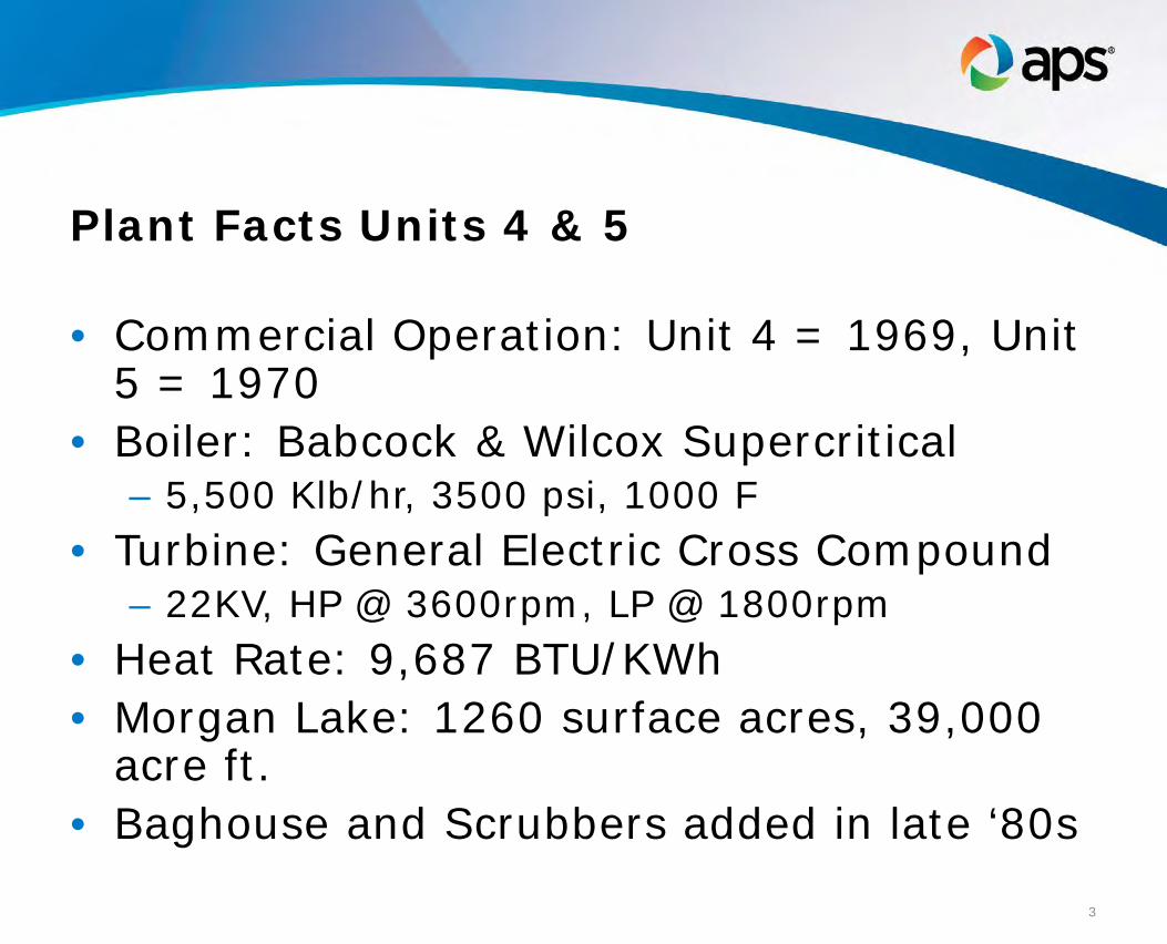
Plant Facts Units 4 & 5
• Commercial Operation: Unit 4 = 1969, Unit 5 = 1970
• Boiler: Babcock & Wilcox Supercritical – 5,500 Klb/hr, 3500 psi, 1000 F
• Turbine: General Electric Cross Compound – 22KV, HP @ 3600rpm, LP @ 1800rpm
• Heat Rate: 9,687 BTU/KWh • Morgan Lake: 1260 surface acres, 39,000
acre ft. • Baghouse and Scrubbers added in late ‘80s
3
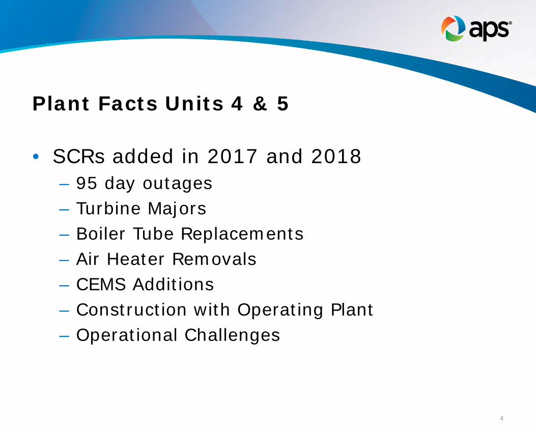
Plant Facts Units 4 & 5
• SCRs added in 2017 and 2018 – 95 day outages – Turbine Majors – Boiler Tube Replacements – Air Heater Removals – CEMS Additions – Construction with Operating Plant – Operational Challenges
4

Questions?
5
Reciprocating Engines – Flexibility for Peaking Operations and
Black Start
Phil Duran Sr. Director, Business Operations
Tyr Energy, Inc.
1
RECIPROCATING ENGINES
Flexibility for Peaking Operationsand Black Start
Phil DuranSr Director – Business Operations
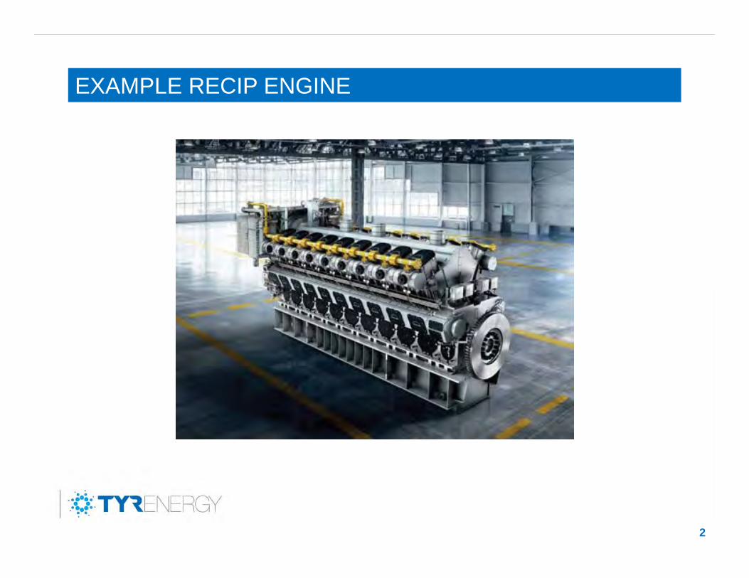
EXAMPLE RECIP ENGINE
2
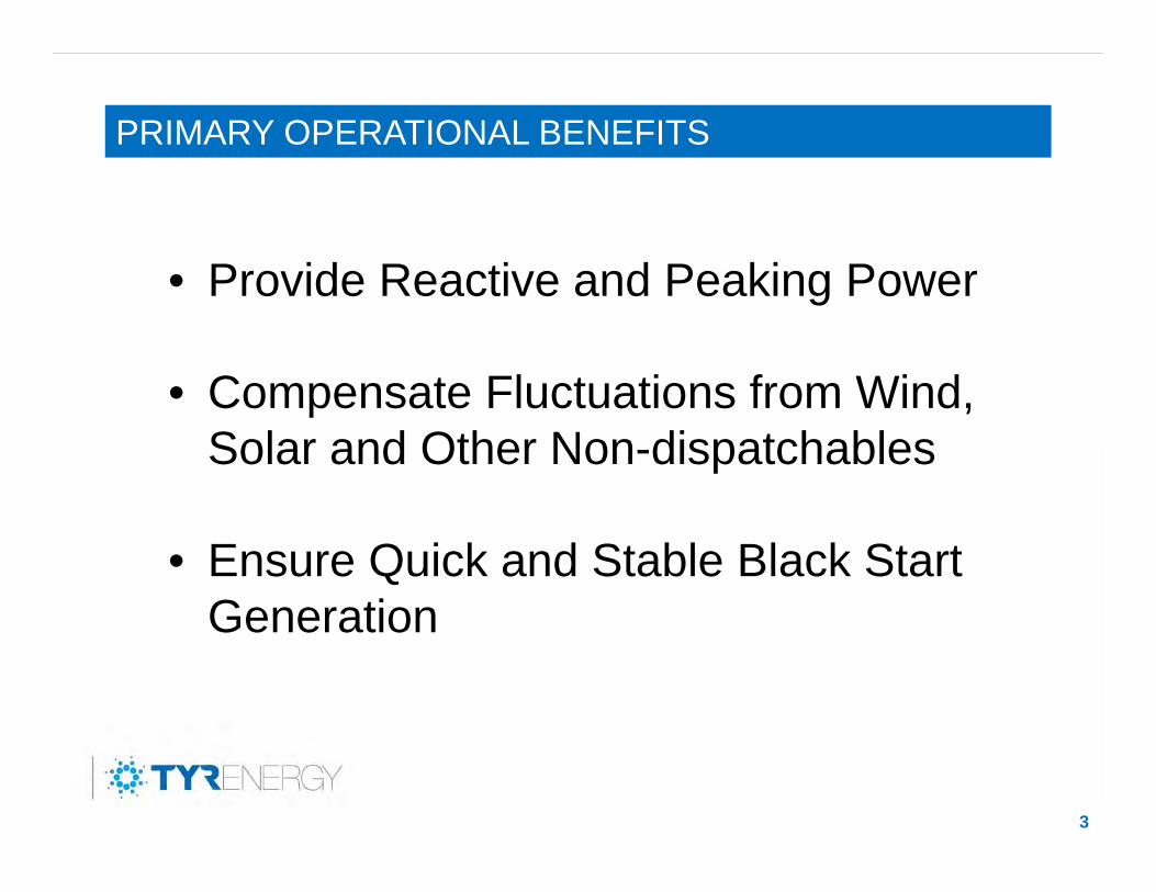
PRIMARY OPERATIONAL BENEFITS
3
• Provide Reactive and Peaking Power
• Compensate Fluctuations from Wind, Solar and Other Non-dispatchables
• Ensure Quick and Stable Black Start Generation
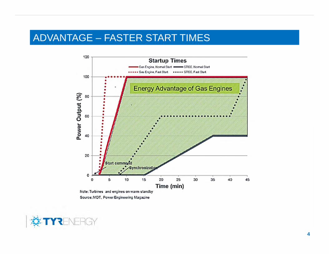
ADVANTAGE – FASTER START TIMES
4
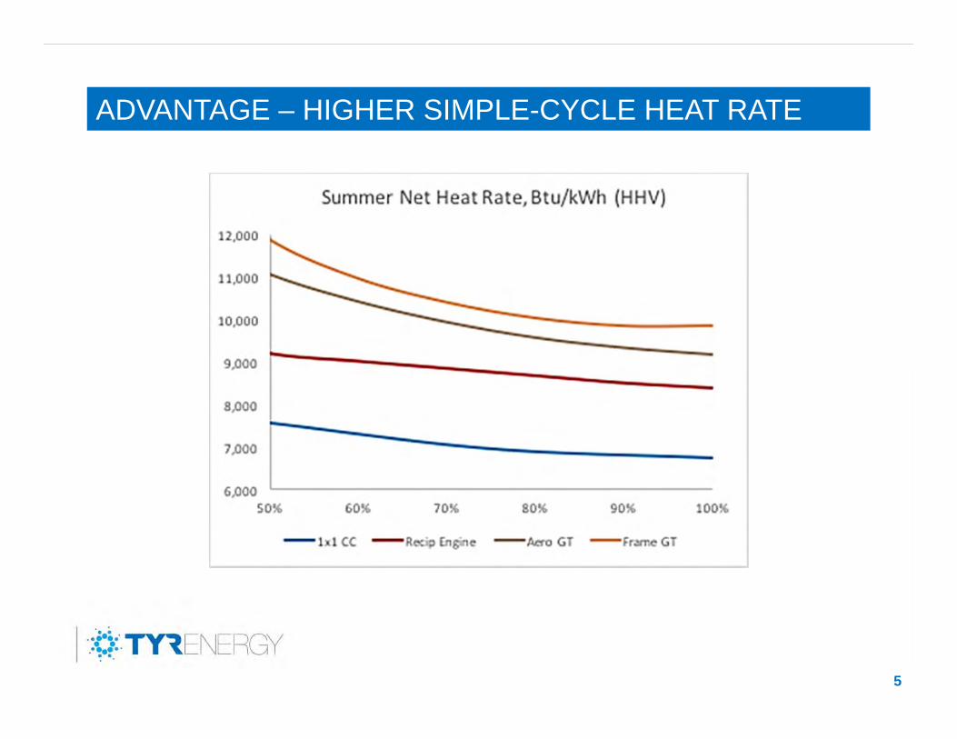
ADVANTAGE – HIGHER SIMPLE-CYCLE HEAT RATE
5
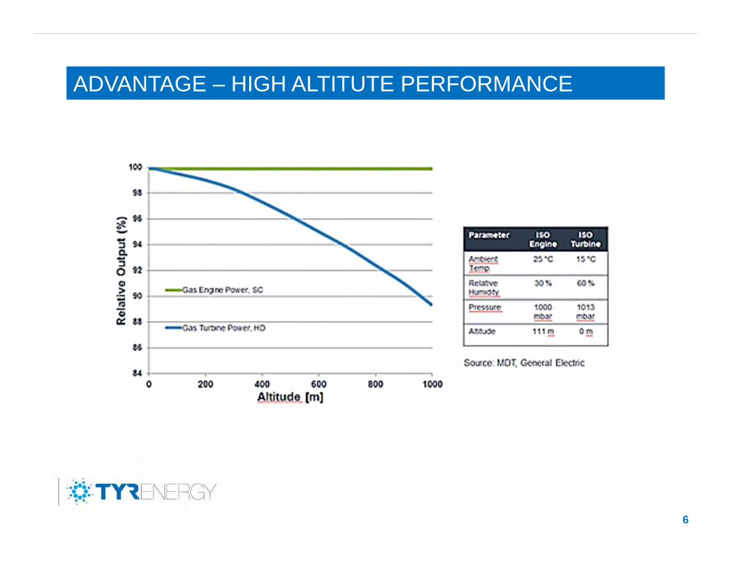
ADVANTAGE – HIGH ALTITUTE PERFORMANCE
6
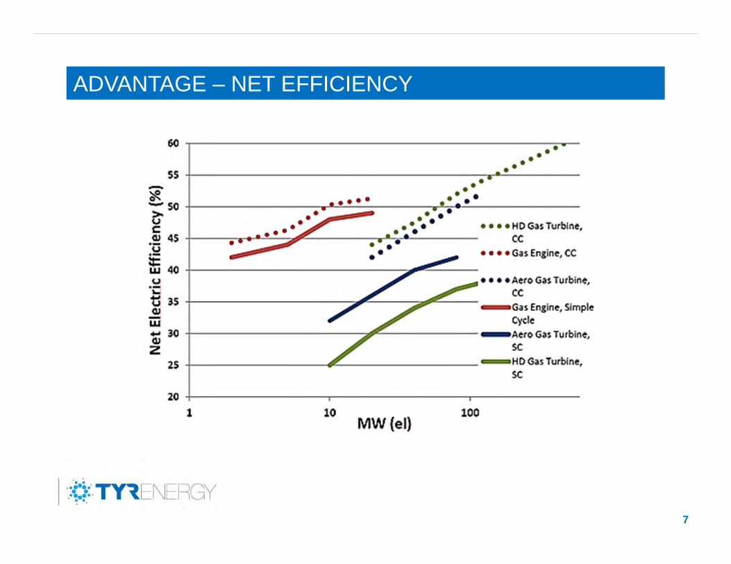
ADVANTAGE – NET EFFICIENCY
7
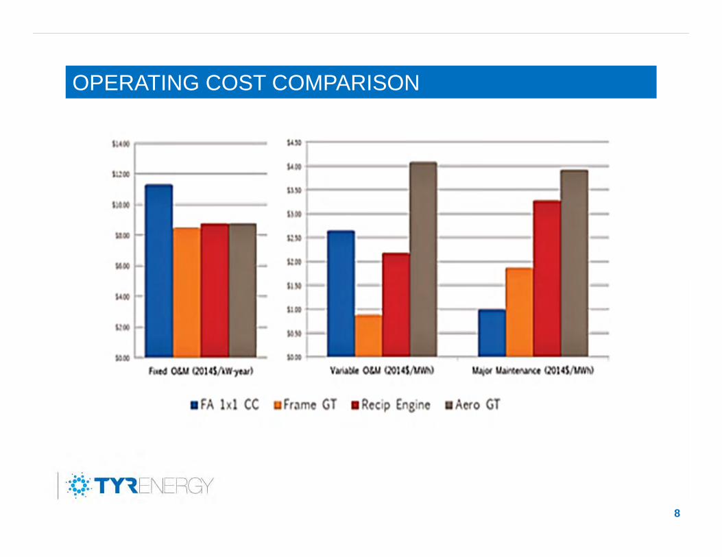
OPERATING COST COMPARISON
8
DISADVANTAGES
9
• Fuel Cost/Efficiency in Base Load Operation at Continuous Full Load
• Power Plant Civil Works (“Foot Print”)
• Higher Total Installed Mass –Challenging in Remote Areas
BREAKERS(1/ENGINE)
230kV SUBSTATION
MAIN STEP-UP TRANSFORMER
480V
13.8kV
480V
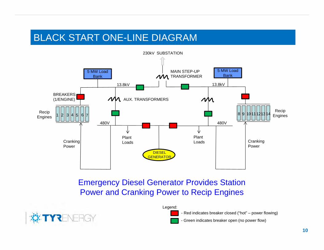
Emergency Diesel Generator Provides Station Power and Cranking Power to Recip Engines
Plant Loads
Legend:- Red indicates breaker closed (“hot” – power flowing)
- Green indicates breaker open (no power flow)
Cranking Power
Cranking Power
DIESELGENERATOR
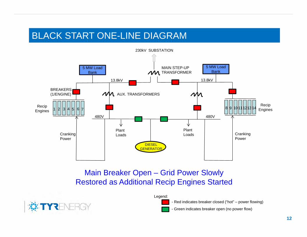
BLACK START ONE-LINE DIAGRAM
10
5 MW Load Bank
1 2 3 4 5 6 7 9 10
5 MW Load Bank
8 11121314
13.8kV
Plant Loads
AUX. TRANSFORMERS
Recip Engines
Recip Engines
BREAKERS(1/ENGINE)
230kV SUBSTATION
MAIN STEP-UP TRANSFORMER
480V
13.8kV
480V
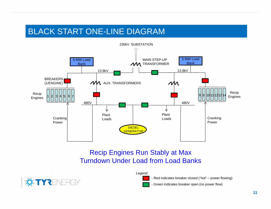
Recip Engines Run Stably at Max Turndown Under Load from Load Banks
Plant Loads
Legend:- Red indicates breaker closed (“hot” – power flowing)
- Green indicates breaker open (no power flow)
Cranking Power
Cranking Power
DIESELGENERATOR
BLACK START ONE-LINE DIAGRAM
11
5 MW Load Bank
1 2 3 4 5 6 7 9 10
5 MW Load Bank
8 11121314
13.8kV
Plant Loads
AUX. TRANSFORMERS
Recip Engines
Recip Engines
BREAKERS(1/ENGINE)
230kV SUBSTATION
MAIN STEP-UP TRANSFORMER
480V
13.8kV
480V
Main Breaker Open – Grid Power Slowly Restored as Additional Recip Engines Started
Plant Loads
Legend:- Red indicates breaker closed (“hot” – power flowing)
- Green indicates breaker open (no power flow)
Cranking Power
Cranking Power
DIESELGENERATOR
BLACK START ONE-LINE DIAGRAM
12
5 MW Load Bank
1 2 3 4 5 6 7 9 10
5 MW Load Bank
8 11121314
13.8kV
Plant Loads
AUX. TRANSFORMERS
Recip Engines
Recip Engines
OPERATOR’S PERSPECTIVE – ADVANTAGES
13
1. Flexible Maintenance Scheduling – One Engine at a Time, No Plant Outage Required
2. Maintenance Cost Spread Over Entire Year as Opposed to One or Two Large Plant Outages
3. High Plant Availability – Very Few Single Point Failures that Affect Entire Plant
OPERATOR’S PERSPECTIVE – DISADVANTAGES
14
1. Higher Maintenance Cost – More Rotating Equipment and Other Moving Parts
2. OEM Support – Improving but Still Lags Behind More Established Technologies
3. Fewer Alternatives to OEM for Parts and Service than for Established Technologies
OFFTAKER’S PERSPECTIVE – ADVANTAGES
15
1. Supplemental Reserves – Quick and Reliable Starts
2. Black Start Resource – Quick Small Load Start and Stable Controlled Ramp Up
3. Fast Ramping Capability – Remote Control of Many Engines with Quick Start and High Turn-down Capability
OFFTAKER’S PERSPECTIVE – DISADVANTAGES
16
1. Higher Cost Power – GT More Efficient (Base Load)
2. Capital Cost per MW for High Capacity
3. None
17
Q & A

Steam Generation and Water Treatment Chemistry – Lessons
Learned and Emerging Technologies
Brad Buecker Sr. Technical Publicist
ChemTreat
Brad BueckerSenior Technical Publicist
ChemTreat
Introduction Many experienced power plant personnel are retiring,
leaving a big gap in knowledge.
Many of the new combined cycle plants that have been or are being constructed are minimally staffed.
A dearth of knowledge (both lessons learned and emerging technologies) exists at many plants regarding critical aspects of steam generation and water treatment chemistry control.
Agenda Overview of five topics
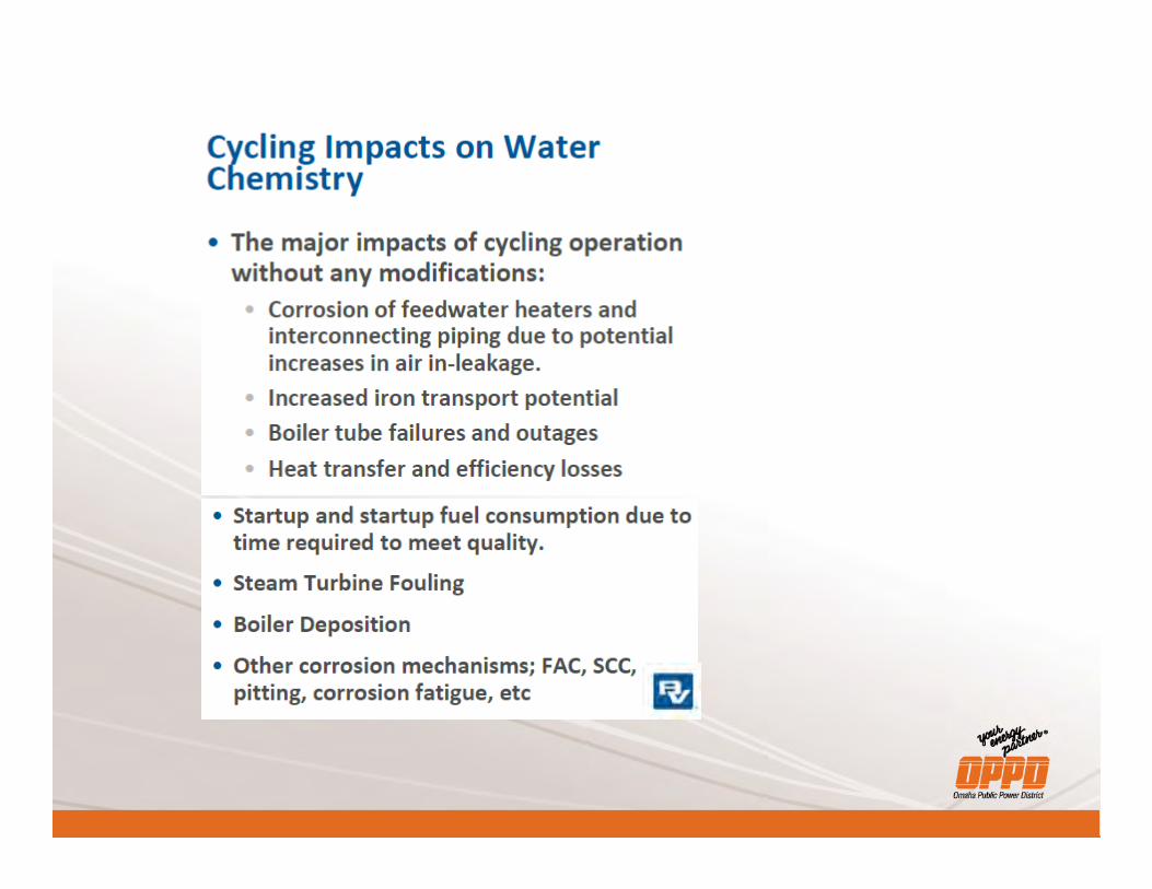
Steam Generation Chemistry #1 – Don’t operate with impurity ingress #2 – Ditch the oxygen scavenger (unless copper alloys are
present) #3 – The importance of layup chemistry
Emerging Cooling Water and Makeup Water Issues #4 – An evolution in cooling water treatment #5 – Makeup water isn’t what it used to be
#1 – Don’t Operate with Impurity Ingress(Condenser Tube Leaks or Otherwise)
#1 Case History – 1250 psig utility boiler
Operators ran the unit for three weeks with a significant condenser leak because the utility was selling the extra power.
Chlorides in the condensate when reaching the boiler induced the following reaction: MgCl2 + 2H2O + heat Mg(OH)2 + 2HCl
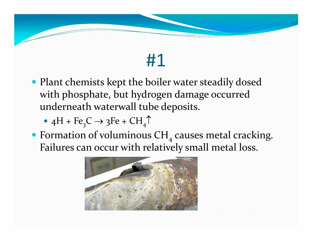
#1 Plant chemists kept the boiler water steadily dosed
with phosphate, but hydrogen damage occurred underneath waterwall tube deposits. 4H + Fe3C 3Fe + CH4
Formation of voluminous CH4 causes metal cracking. Failures can occur with relatively small metal loss.
#1 The leak was corrected, but within two months boiler
tubes began failing regularly due to hydrogen damage. The unit had to be shut down, and all waterwall tubes
replaced. Very negative return-on-investment for the three
weeks of power sales.
#1 Impurities can also induce other corrosion
mechanisms such as corrosion fatigue (CF) and stress corrosion cracking (SCC).
Also critical is prevention of impurity carryover to steam. Sodium, chloride, and sulfate limits are at 2 ppb due to
the damage these impurities can cause in the steam system and turbine. Pitting, CF, and SCC of turbine blades, especially in the LP
section Blade failure may be the end result.
#2 – The Continuing Crusade AgainstOxygen Scavengers
#2 For years, EPRI and IAPWS have strongly
recommended against oxygen scavenger (reducing agent) treatment in steam generator feedwater systems containing no copper alloys. Applies to virtually all HRSGs
Yet, many combined-cycle specifications still contain language for oxygen scavenger feed. Oxygen scavenger combined with ammonia (or amine)
feed for pH control is known as all-volatile treatment reducing [AVT(R)].
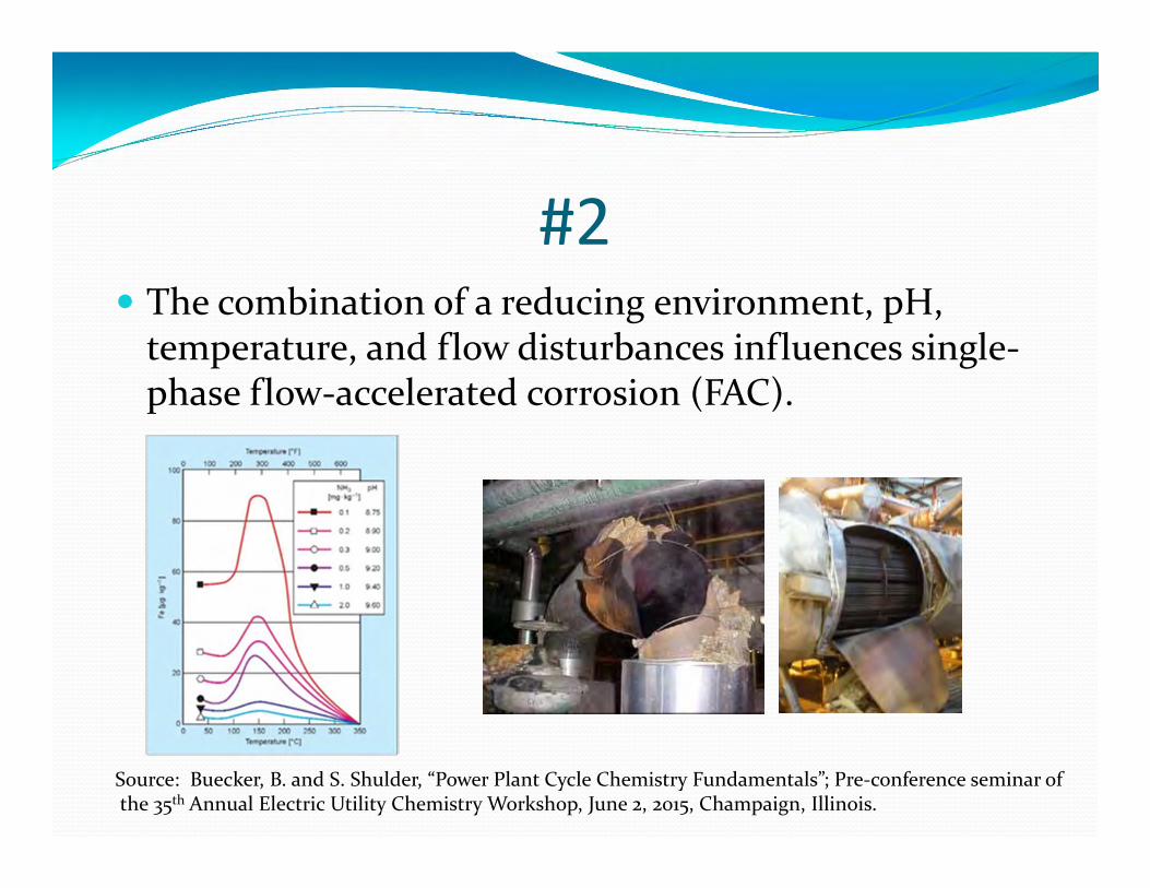
#2 The combination of a reducing environment, pH,
temperature, and flow disturbances influences single-phase flow-accelerated corrosion (FAC).
Source: Buecker, B. and S. Shulder, “Power Plant Cycle Chemistry Fundamentals”; Pre-conference seminar ofthe 35th Annual Electric Utility Chemistry Workshop, June 2, 2015, Champaign, Illinois.
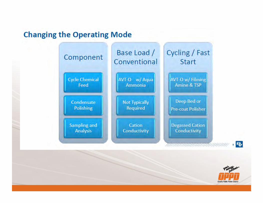
#2 The recommended program for drum units is all-
volatile treatment oxidizing [AVT(O)]. No reducing agent feed, only ammonia for pH
conditioning Allow oxygen that enters through condenser air in-leakage to
carry through the system.
Recommended feedwater D.O. concentration of 5 to 10 ppb. For plants with deaerators, may have to close the vents. Supplemental pure oxygen injection may be required.
Condensate pump discharge and LP evaporator discharge
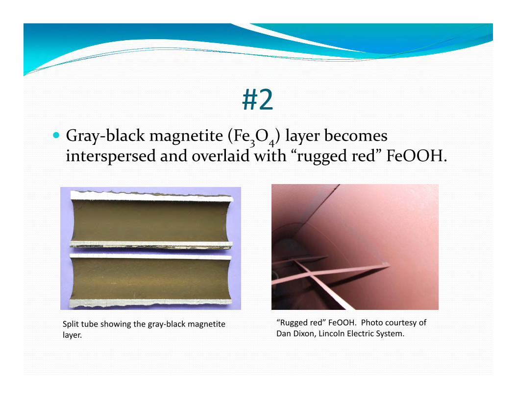
#2 Gray-black magnetite (Fe3O4) layer becomes
interspersed and overlaid with “rugged red” FeOOH.
Split tube showing the gray-black magnetitelayer.
“Rugged red” FeOOH. Photo courtesy of Dan Dixon, Lincoln Electric System.
#2 Condensate/feedwater must be very pure (cation
conductivity less than 0.2 µS/cm). Maintain pH in the proper alkaline range.
9.2-9.8 or 9.6-10.0 depending upon boiler configuration Higher range is recommended in some units to
minimize two-phase FAC. Operating at high pH range can require a significant
amount of ammonia. Blending in some neutralizing amine may help, but
decomposition products are of concern.
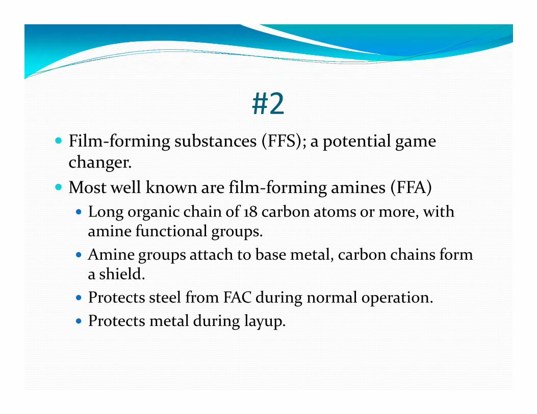
#2 Film-forming substances (FFS); a potential game
changer. Most well known are film-forming amines (FFA)
Long organic chain of 18 carbon atoms or more, with amine functional groups.
Amine groups attach to base metal, carbon chains form a shield.
Protects steel from FAC during normal operation. Protects metal during layup.
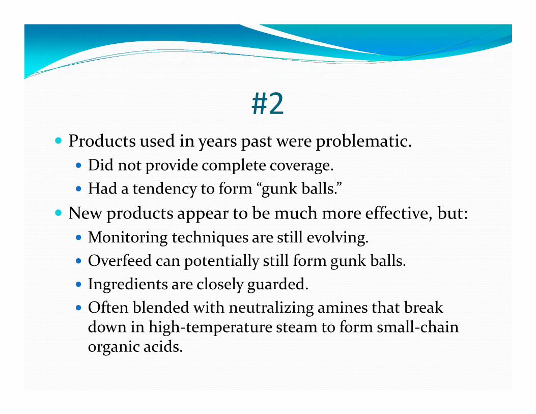
#2 Products used in years past were problematic.
Did not provide complete coverage. Had a tendency to form “gunk balls.”
New products appear to be much more effective, but: Monitoring techniques are still evolving. Overfeed can potentially still form gunk balls. Ingredients are closely guarded. Often blended with neutralizing amines that break
down in high-temperature steam to form small-chain organic acids.
#3 – Layup Protection
#3 Corrosion in poorly-protected units during downtimes
can be extremely severe. Air ingress is the primary culprit. Steam generators and turbines need protection.
Good layup practices are followed by RMEL member Lincoln Electric System for the two HRSGs at the LES Terry Bundy plant. Following slides taken from C. Hodges and B. Buecker, “An Ounce of
Prevention. . . .”; 38th Annual Electric Utility Chemistry Workshop, June 5-7, 2018, Champaign, Illinois.
#3 Layup Guiding Principles
1. Maintain same oxidation/reduction potential (ORP) for wet layup as for operation
2. Keep air away from water & avoid stagnant conditions
3. Keep moisture away from components meant or intended to be kept dry
#3 Actions to meet steady ORP
Normal Operation: AVT(O) chemistry with ammonia feed to maintain pH at 10. No reducing agent
Into Shutdown: Ensure pH remains at 10. No reducing agent A uniform protective oxide would be unable to form if the
environment was switched from an oxidized state during operation to a reduced state during layup.
Nitrogen capping helps to maintain steady ORP.
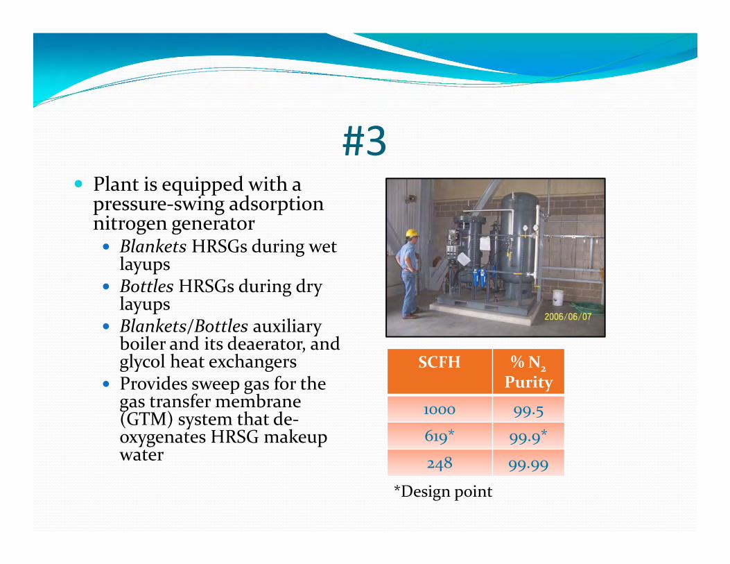
#3 Plant is equipped with a
pressure-swing adsorption nitrogen generator Blankets HRSGs during wet
layups Bottles HRSGs during dry
layups Blankets/Bottles auxiliary
boiler and its deaerator, and glycol heat exchangers
Provides sweep gas for the gas transfer membrane (GTM) system that de-oxygenates HRSG makeup water
SCFH % N2Purity
1000 99.5
619* 99.9*
248 99.99
*Design point
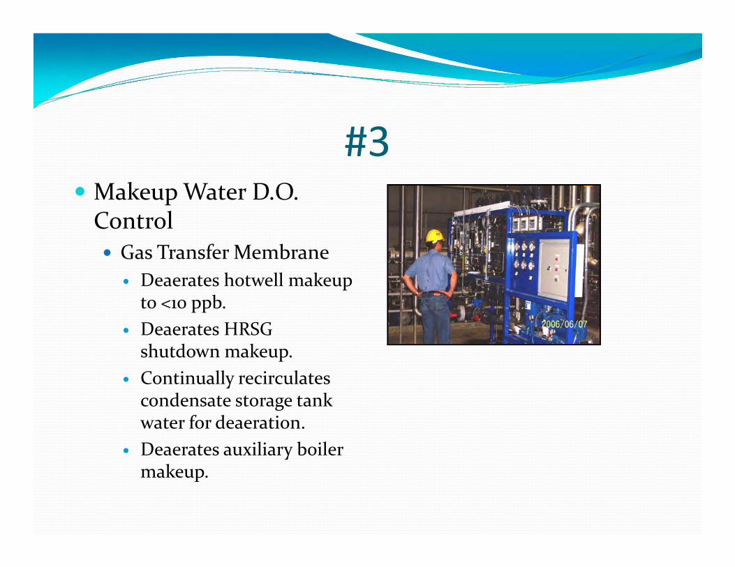
#3 Makeup Water D.O.
Control Gas Transfer Membrane
Deaerates hotwell makeup to <10 ppb.
Deaerates HRSG shutdown makeup.
Continually recirculates condensate storage tank water for deaeration.
Deaerates auxiliary boiler makeup.
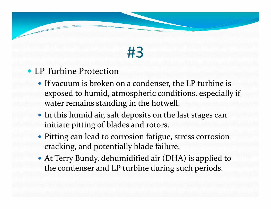
#3 LP Turbine Protection
If vacuum is broken on a condenser, the LP turbine is exposed to humid, atmospheric conditions, especially if water remains standing in the hotwell.
In this humid air, salt deposits on the last stages can initiate pitting of blades and rotors.
Pitting can lead to corrosion fatigue, stress corrosion cracking, and potentially blade failure.
At Terry Bundy, dehumidified air (DHA) is applied to the condenser and LP turbine during such periods.
#3
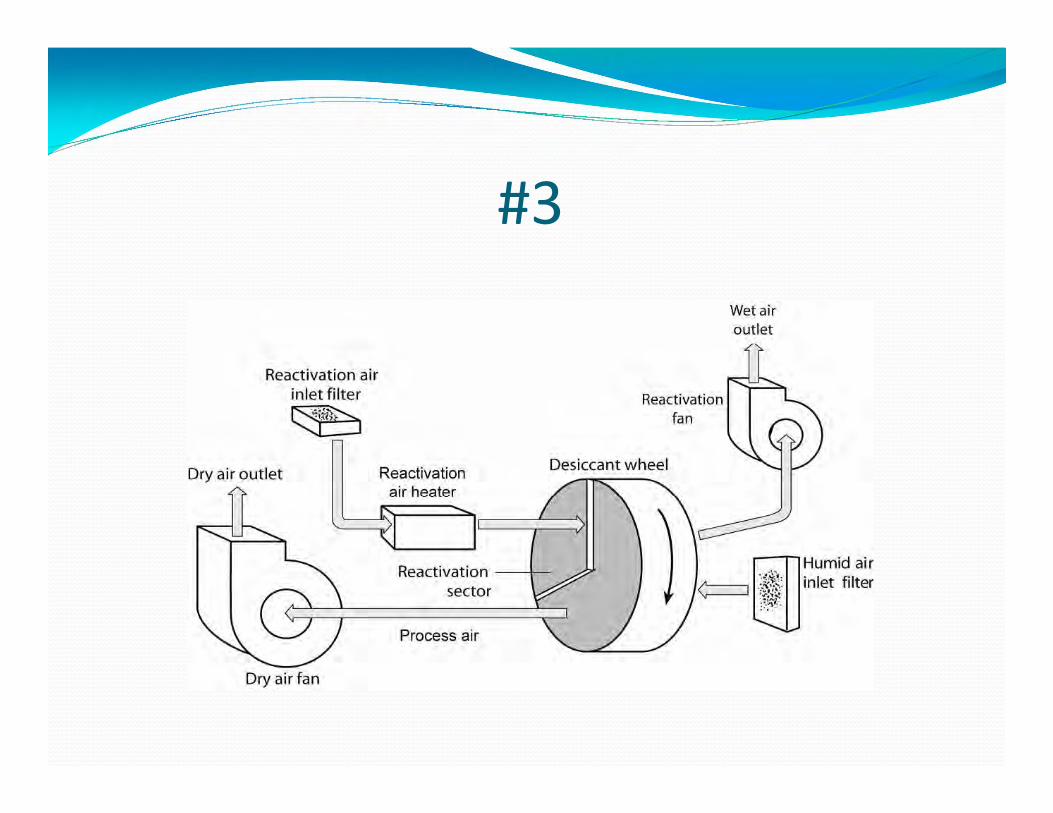
#3 Rotary Desiccant Wheel Dehumidifier Skid
Applies warm, DHA into the LP steam turbine injection line to dry the turbine to prevent: Pitting Corrosion fatigue Stress corrosion cracking
Secondary objective is to dry the hotwell to minimize general corrosion
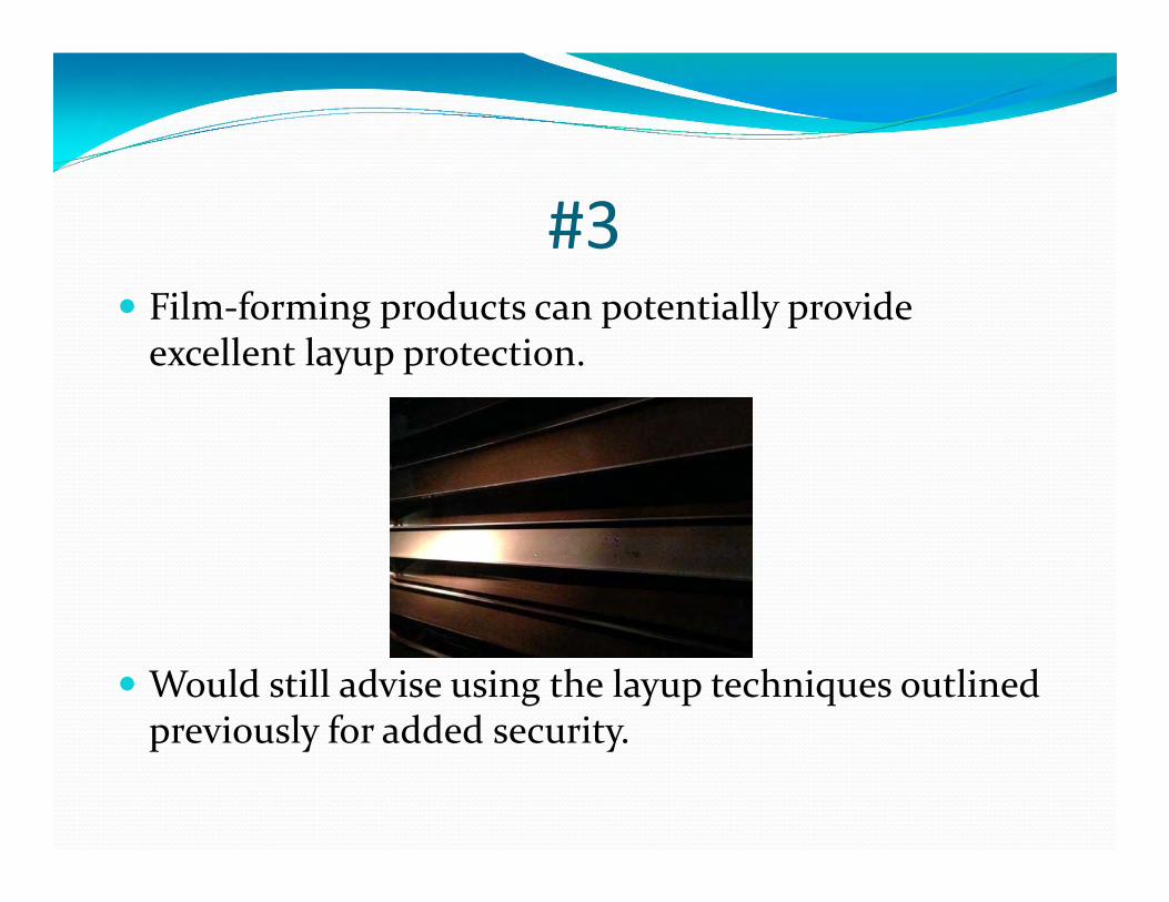
#3 Film-forming products can potentially provide
excellent layup protection.
Would still advise using the layup techniques outlined previously for added security.
#4 – Evolution of Cooling Water Scale/Corrosion And Microbiological
Control Methods
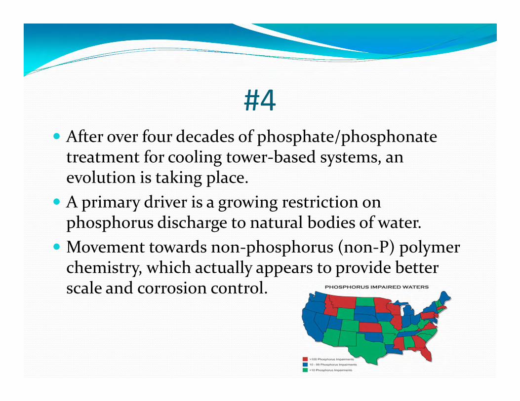
#4 After over four decades of phosphate/phosphonate
treatment for cooling tower-based systems, an evolution is taking place.
A primary driver is a growing restriction on phosphorus discharge to natural bodies of water.
Movement towards non-phosphorus (non-P) polymer chemistry, which actually appears to provide better scale and corrosion control.
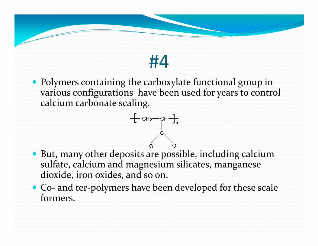
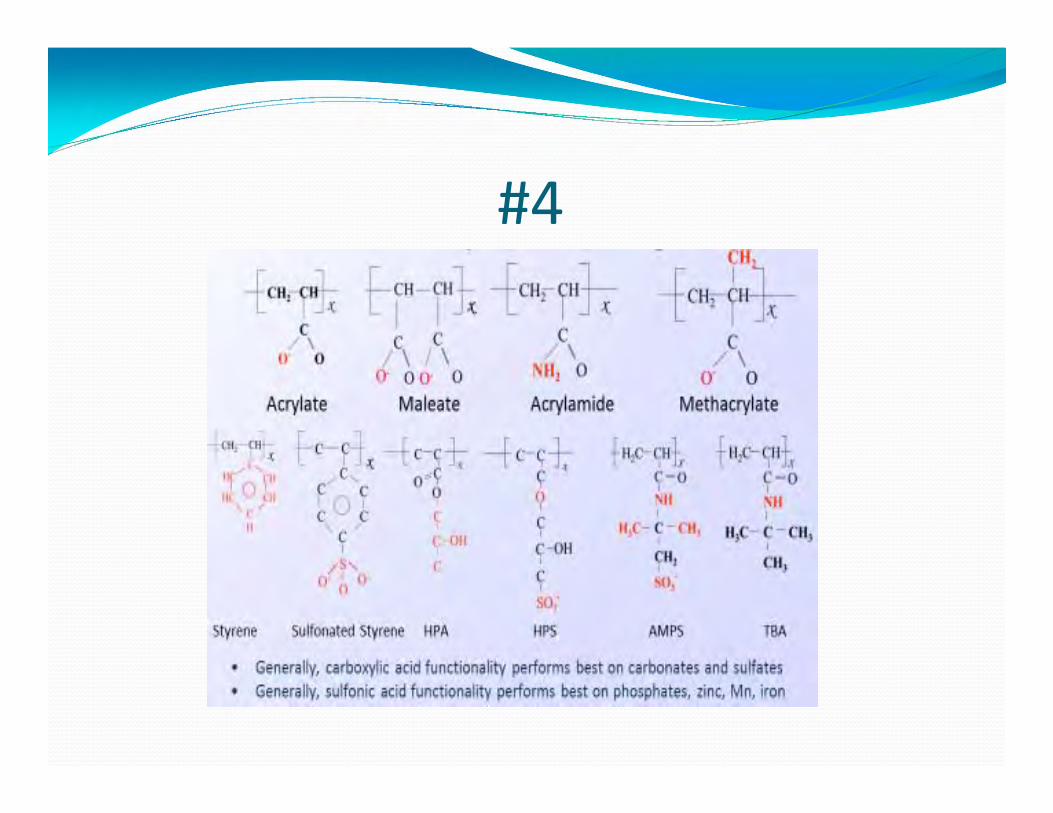
#4 Polymers containing the carboxylate functional group in
various configurations have been used for years to control calcium carbonate scaling.
But, many other deposits are possible, including calcium sulfate, calcium and magnesium silicates, manganese dioxide, iron oxides, and so on.
Co- and ter-polymers have been developed for these scale formers.
#4
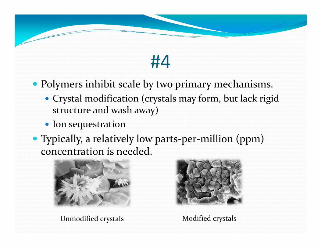
#4 Polymers inhibit scale by two primary mechanisms.
Crystal modification (crystals may form, but lack rigid structure and wash away)
Ion sequestration Typically, a relatively low parts-per-million (ppm)
concentration is needed.
Unmodified crystals Modified crystals
#4 But what about corrosion protection?
Phosphate/phosphonate programs inhibit corrosion by precipitation of reactants at anodes and cathodes on the metal. Calcium phosphate and polyphosphate Iron phosphate Zinc hydroxide
This chemistry can be rather complex. Under-dosing – Potential for corrosion and deposition Over-dosing – Potential for heavy calcium phosphate
deposition
#4 A corrosion control supplement to polymer chemistry
is a formulation known as reactive polyhydroxy starch inhibitor (RPSI).
Active groups on the material bind to metal surfaces to form a protective coating. Functions include: General corrosion protection of carbon steel Passivation of rusted steel surfaces Improved protection of stainless steels from chloride-
induced crevice and pitting corrosion Doesn’t rely on deposition chemistry like the
phosphate/phosphonate programs
#4 As contrasted to phosphate/phosphonate programs,
RPSI does not rely on deposition products to inhibit anodic and cathodic reactions.
The next slide shows the results of the chemistry in the cleaning solution (and subsequent standard treatment) of a wet-surface air cooler (WSAC®) at a natural gas liquid (NGL) fractionation plant on the U.S. Gulf Coast.
Data from another full-scale application showed a corrosion rate reduction of nearly two orders of magnitude.
#4
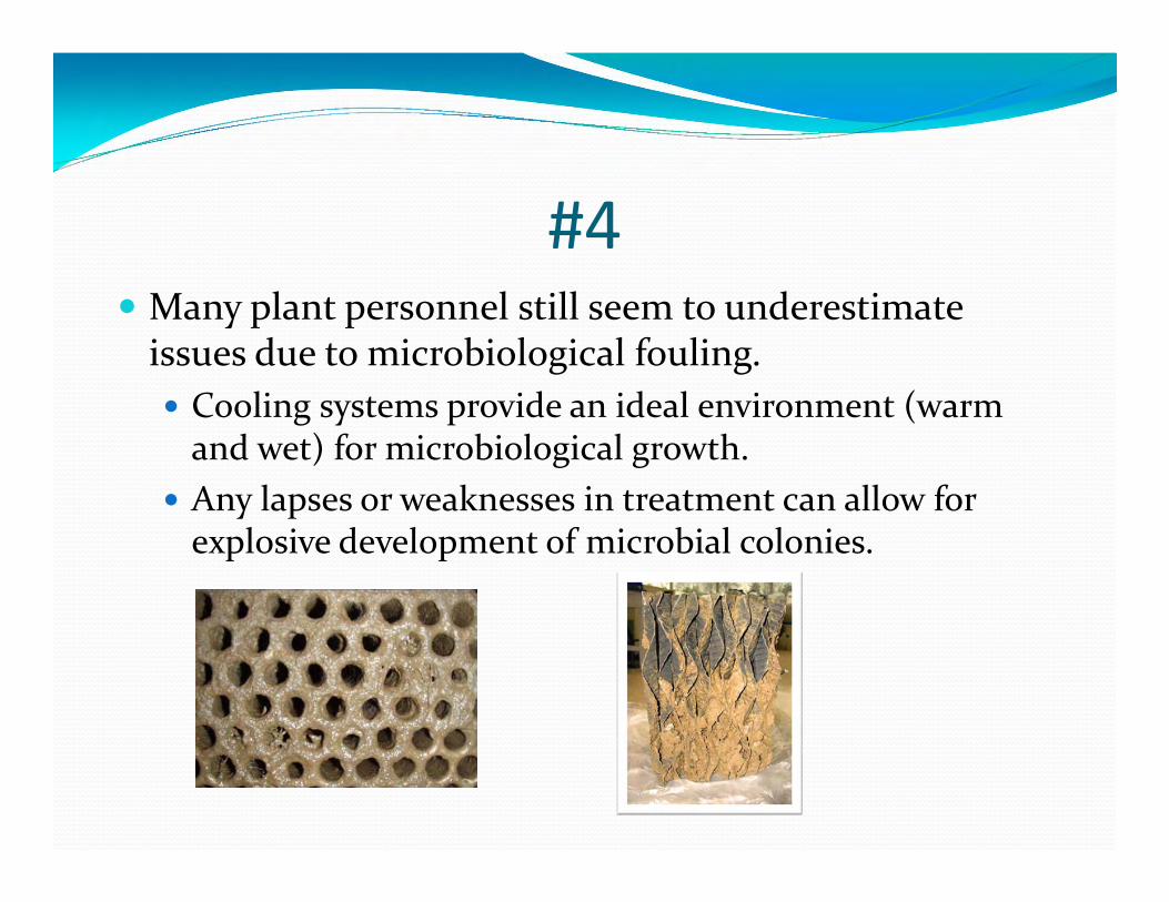
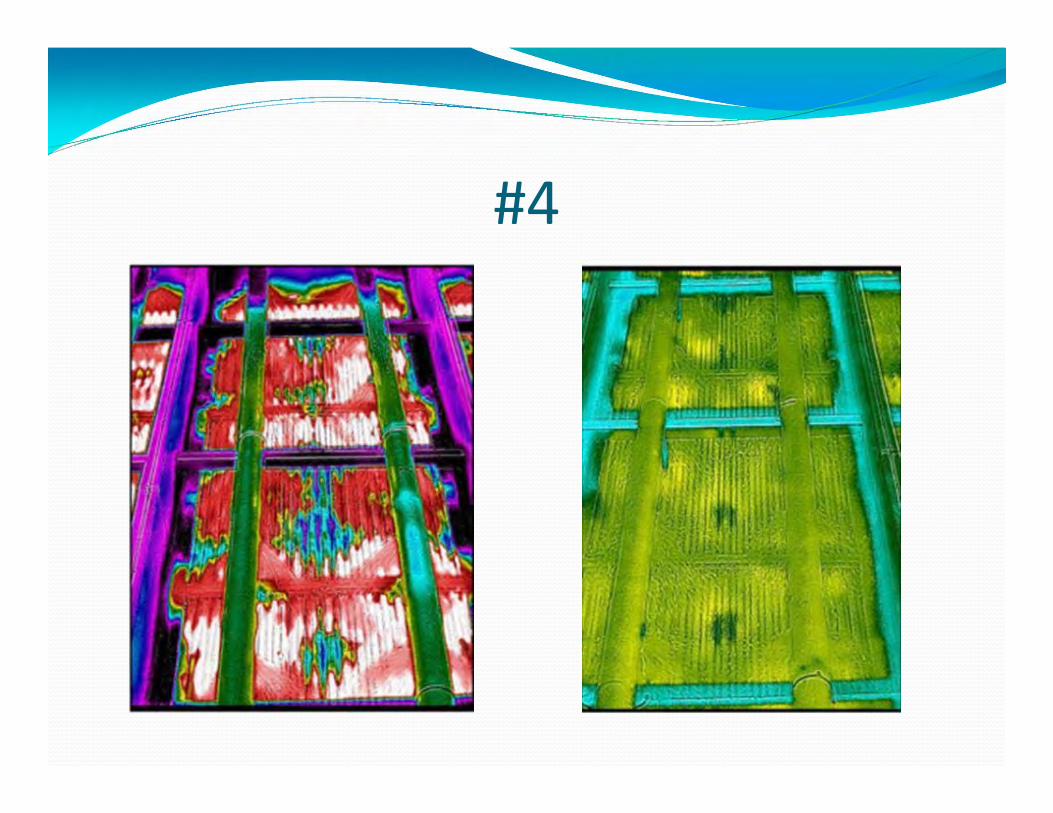
#4 Many plant personnel still seem to underestimate
issues due to microbiological fouling. Cooling systems provide an ideal environment (warm
and wet) for microbiological growth. Any lapses or weaknesses in treatment can allow for
explosive development of microbial colonies.
The core of any treatment program is an oxidizing biocide.
Gaseous chlorine was the preferred choice for years. Cl2 + H2O HOCl + HCl Hypochlorous acid (HOCl) is the killing agent. Least expensive method
General shift to bleach (sodium hypochlorite, NaOCl) due to safety concerns
Successful applications of on-site bleach generation
#4
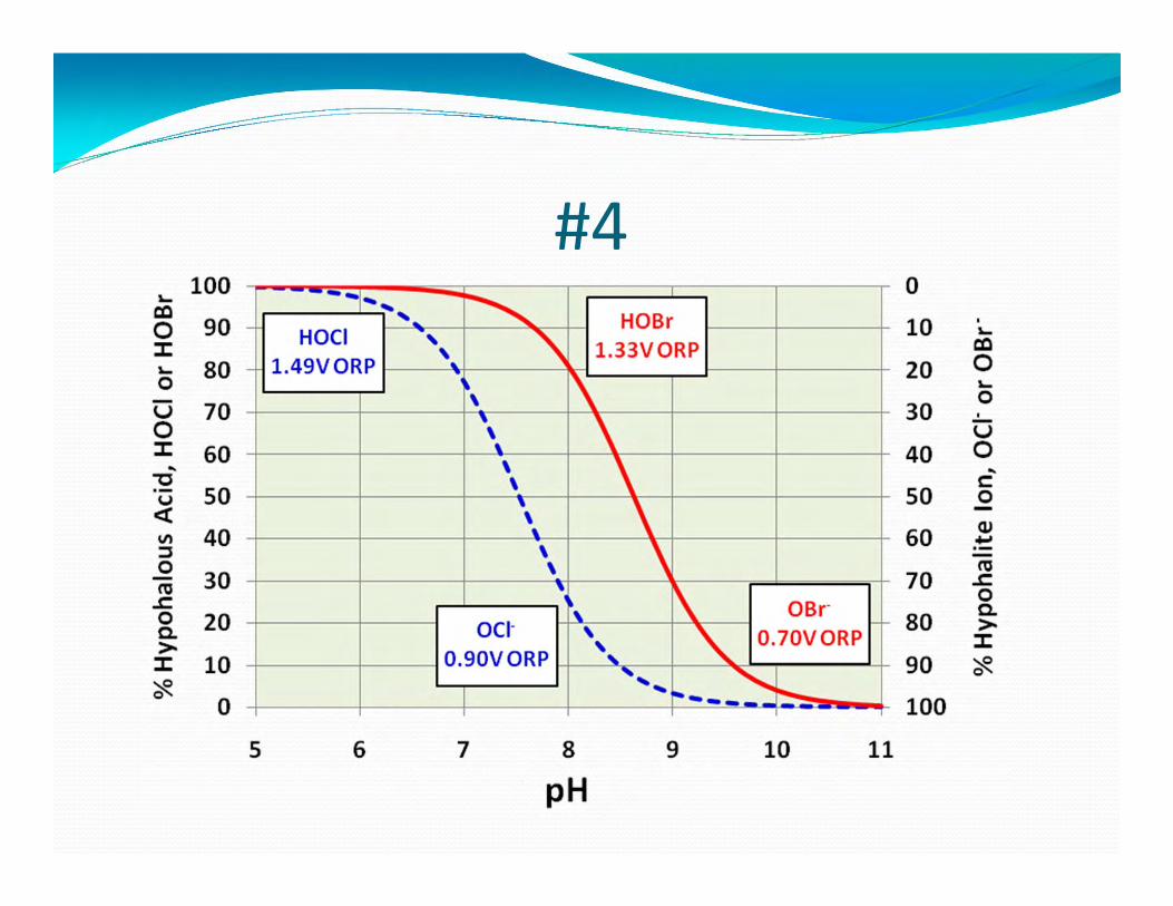
#4 The slight basicity of many makeup waters (pH near or
slightly above 8) makes chlorine somewhat ineffective due to dissociation of hypochlorous acid. HOCl H+ + OCl-
OCl- much less potent killing agent Chlorine also reacts irreversibly with ammonia, and it
will produce halogenated organic compounds that may be of concern.
Modified or alternative oxidizing programs are common.
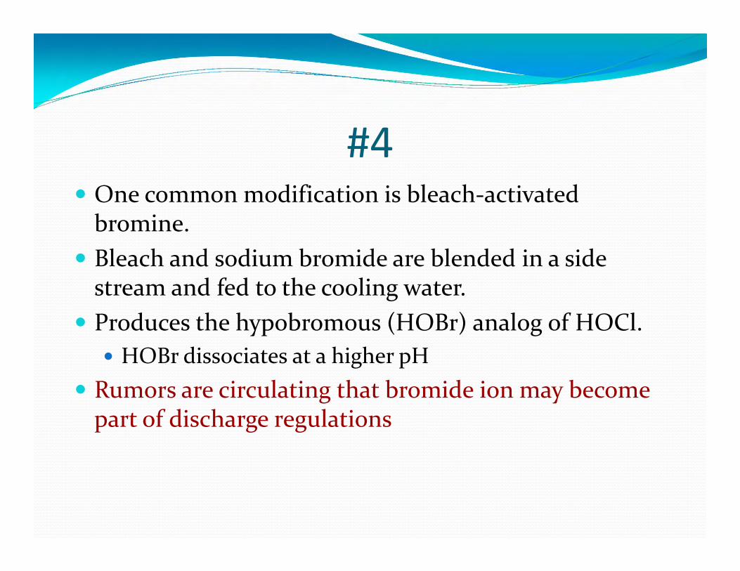
#4 One common modification is bleach-activated
bromine. Bleach and sodium bromide are blended in a side
stream and fed to the cooling water. Produces the hypobromous (HOBr) analog of HOCl.
HOBr dissociates at a higher pH Rumors are circulating that bromide ion may become
part of discharge regulations
#4
#4 Another alternative is chlorine dioxide (ClO2)
Must be produced on-site. Not affected by pH. Does not react with ammonia. More expensive than other methods
Others include specially-prepared monochloramine(NH2Cl) and monobromamine (NH2Br). Not as powerful oxidizers, but appear to better penetrate
the protective slime layer formed by bacteria. Also, solid products like the hydantoins
#4 Non-oxidizing biocides can deliver a “one-two punch”
to microorganisms. Feed perhaps once per week for one hour, or some
similar schedule. Non-oxidizers are basically divided into two classes:
Metabolic inhibitors Surface active agents
Selection influenced by the need to control bacteria, algae, or fungi, or a combination.
Safety and discharge permitting are important issues.
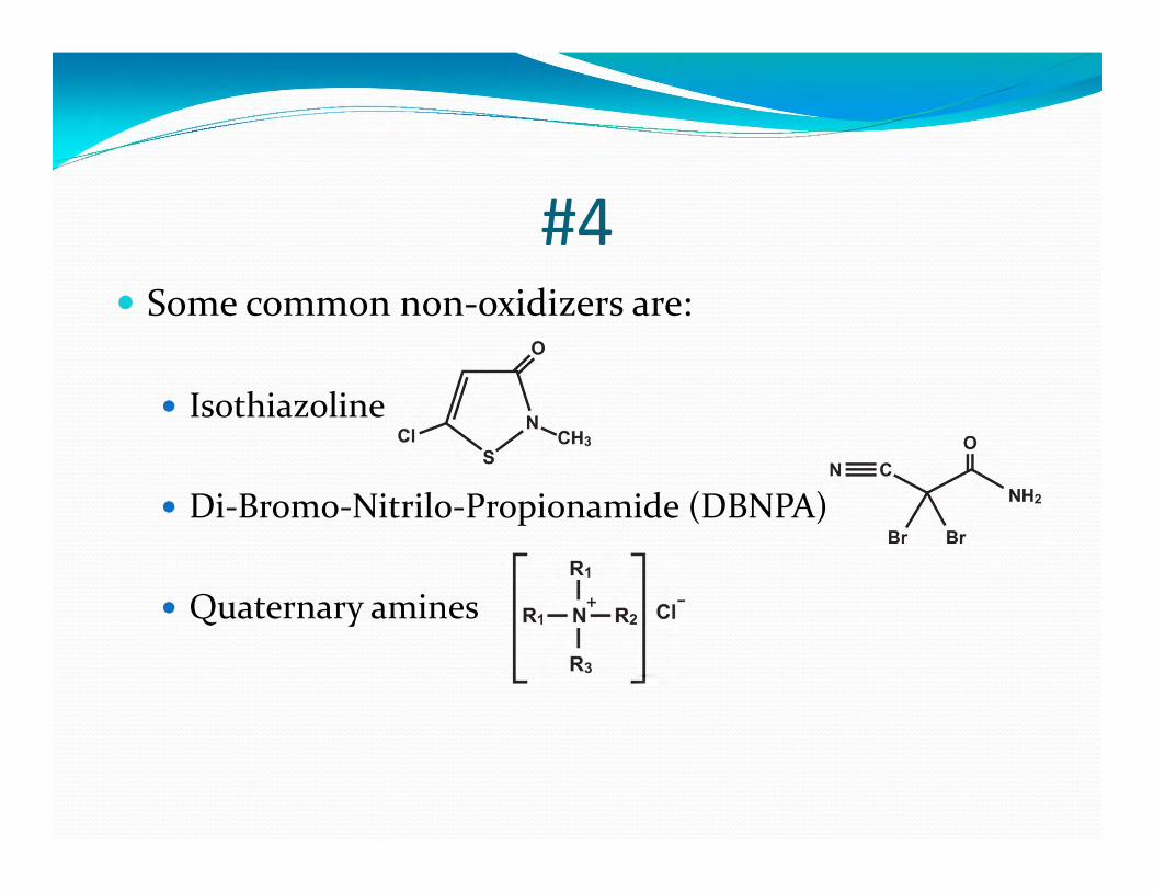
#4 Some common non-oxidizers are:
Isothiazoline
Di-Bromo-Nitrilo-Propionamide (DBNPA)
Quaternary amines

#5 – Increasing Complexity of MakeupWater Treatment
#5 Fresh water is becoming more scarce.
By choice or mandate, personnel at new plants are selecting alternative supplies.
One rapidly emerging alternative is effluent from a publicly owned treatment works (POTW), i.e., municipal wastewater treatment plant.
#5 POTW effluent often contains significant
concentrations of ammonia, nitrate/nitrite, organics, and phosphate.
These are nutrients and food for microorganisms. Can cause intense growth in cooling systems. Without pretreatment, only splash fill may be allowed in
the cooling tower. Ammonia and organics, typically in fluctuating
concentrations, can play havoc with biocide feed.
#5 Two technologies becoming popular for pre-treatment
are membrane bioreactors (MBR) and moving-bed bioreactors (MBBR).
Both use beneficial microorganisms to consume nutrients and food, producing a clean effluent.
Advanced technology over the old trickling bed filters and conventional activated sludge processes.
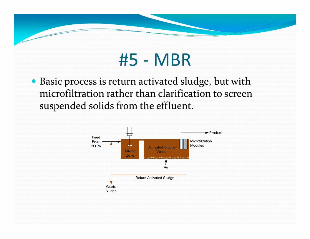
#5 - MBR Basic process is return activated sludge, but with
microfiltration rather than clarification to screen suspended solids from the effluent.
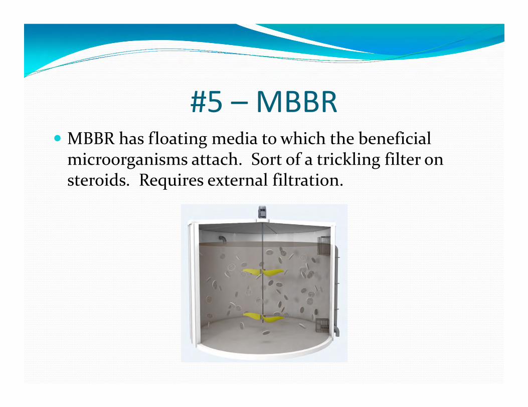
#5 – MBBR MBBR has floating media to which the beneficial
microorganisms attach. Sort of a trickling filter on steroids. Requires external filtration.
#5 The basic MBR and MBBR systems shown in the
previous slides will consume organics and phosphorus. But most of the ammonia is only converted to
nitrite/nitrate. Inclusion of anoxic or anaerobic reaction vessels in the
design will convert nitrogen species to elemental nitrogen. Consider early in the design phase whether complete nitrogen
conversion is needed.
#5 There is reluctance in the power industry to operate
such seemingly sophisticated pre-treatment systems. Potential solutions include: If the POTW is nearby, place the system at that site and
have the POTW personnel operate it. Reputable vendors will supply equipment on a build-
own-operate-maintain (BOOM) basis.
Conclusion Examples above outlined a number of the most
important issues/trends in the power industry. These concepts often are not recognized at new plants
due to minimal staffing and loss of experienced personnel to retirement.
Lack of understanding can cause operating problems, induce very expensive failures, and, in some cases, lead to safety issues.