PLANNING GUIDE - HYUNDAI · PDF file2 The selection of elevators should be made in...
21
AFRICA GHANA Tel : 233-243-822-222 E-mail : [email protected] TANZANIA Tel : 255-754-281-580 E-mail : [email protected] ALGERIA Tel : 213-661-25-22-44 E-mail : bentchakal,mohamed@ gmail.com EGYPT Tel : 20-2-25078503 E-mail : overseas@iet-hyundaielevator. com ETHIOPIA Tel : 251-118-605051 E-mail : [email protected] KENYA Tel : 254-722-523-695 E-mail : [email protected] NIGERIA Tel : 234-803-7352222 E-mail : [email protected] REPUBLIC OF SOUTH AFRICA Tel : 27-87-150-3550 E-mail : [email protected] SUDAN Tel : 249-912-162-995 E-mail : [email protected] TUNISIA Tel : 216-71-962-967 E-mail : [email protected] ASIA BANGLADESH Tel : 880-171-320-9212 E-mail : [email protected] CAMBODIA Tel : 855-2388-8399 E-mail : [email protected] CHINA [Head Office(Factory)] Tel : 86-21-6485-8600 E-mail : [email protected] INDIA Tel : 91-97300-65177 E-mail : [email protected] INDONESIA Tel : 62-21-631-8444 E-mail : [email protected] MALAYSIA Tel : 603-6733-1919 E-mail : [email protected] MONGOLIA Tel : 976-8908-3055 E-mail : [email protected] MYANMAR Tel : 959-400444598 E-mail : [email protected] NEPAL Tel : 977-1-4111780 E-mail : [email protected] PAKISTAN Tel : 92-21-432-0604 E-mail : [email protected] PHILIPPINES Tel : 632-716-0905 E-mail : [email protected] SRI LANKA Tel : 94-11-2623208 E-mail : [email protected] THAILAND Tel : 66-81-2348-8787 E-mail : [email protected] VIETNAM Tel : 84-04-62822978 E-mail : [email protected] EUROPE & CIS ARMENIA Tel : 374-060-50-90-70 E-mail : [email protected] [email protected] AZERBAIJAN Tel : 994-12-555-1744~46 E-mail : offi[email protected] HUNGARY Tel : 36-46-505-938 E-mail : [email protected] KAZAKHSTAN Tel : 7-778-777-7570 E-mail : [email protected] KYRGYZSTAN Tel : 996-559-918-885 E-mail : [email protected] MAKEDONIA Tel : 90-538-097-5451 E-mail : [email protected] POLAND Tel : 48-61-820-8551 E-mail : maciej.dziurkiewicz@ omilifts.com TURKEY Tel : 90-538-097-5451 E-mail : [email protected] RUSSIA [Moscow] Tel : 7-495-668-07-15 E-mail : [email protected] [Vladi] Tel : 7-423-220-51-16 E-mail : [email protected] MIDDLE EAST BAHRAIN Tel : 973-17-702-468 E-mail : [email protected] IRAN Tel : 98-21-8869-8727~36 E-mail : jafari_hyundai2015@yahoo. com IRAQ Tel : 964-770-588-0555 E-mail : [email protected] ISRAEL Tel : 972-3-9630000 E-mail : [email protected] JORDAN Tel : 962-79-5526-713 E-mail : [email protected] KUWAIT Tel : 965 2245-7925 - Ext. 118/0 E-mail : [email protected] OMAN Tel : 968-24619415 E-mail : [email protected] QATAR Tel : 974-436-6689 E-mail : [email protected] SAUDI ARABIA Tel : 966-12-6683555 E-mail : [email protected] UAE Tel : 971-4-2944-475 E-mail : [email protected] YEMEN Tel : 967-1-450556 E-mail : [email protected] LEBANON Tel : 961-70774470 E-mail : [email protected] NORTH/SOUTH AMERICA ARGENTINA Tel : 5411-3220-2878 E-mail : [email protected] BRAZIL [Head office] Tel : 55-51-8913-6975 E-mail : [email protected] [Sao Paulo (Sales office)] Tel : 55-11-99894-2567 E-mail : [email protected] CHILE Tel : 569–225540849 E-mail : [email protected] COLOMBIA Tel : 57-4-444-9297 E-mail : sgiraldo@solucionesver ticales.com.co COSTA RICA Tel : 506-7013-4407 E-mail : [email protected] CUBA Tel : 537-2042046 E-mail : [email protected] DOMINICAN REPUBLIC Tel : 809-566-7474 E-mail : [email protected] ECUADOR Tel : 593-2254-2831 E-mail : [email protected] GUATEMALA Tel : 502-5018-1868 E-mail : [email protected] MEXICO Tel : 52-55-5663-2019 E-mail : [email protected] PANAMA Tel : 507-230-3166 E-mail : asucre@elevadoresdelistmo. com VENEZUELA Tel : 58-212-232-8263 E-mail : [email protected] PERU Tel : 51-988-488-425 E-mail : [email protected] EL SALVADOR Tel : 503-2261-1549 E-mail : [email protected] HONDURAS Tel : 504-2564-6150 504-2231-3302 E-mail : [email protected] NICARAGUA Tel : 505-2223-5217 E-mail : [email protected] HEAD OFFICE & FACTORY 2091, Gyeongchungdero, Bubal-eup, Icheon-si, Gyeonggi-do, 17336, Korea www.hyundaielevator.com SEOUL OFFICE (GLOBAL SALES DIV.) 5F, East Bldg., Hyundai Group Bldg., 194, Youlgok-ro, jongno-gu, Seoul, 03127, Korea Tel : 82-2-3670-0660 PLANNING GUIDE - We reserve the right to change designs and specifications for the product development without prior notice. Copyright ⓒ HYUNDAI ELEVATOR CO., LTD. All rights reserved. Printed in Korea. C-EPG-E1805 / 2018. 03 / Revision 18 GLOBAL SALES & SERVICE NETWORK
Transcript of PLANNING GUIDE - HYUNDAI · PDF file2 The selection of elevators should be made in...
AFRICAGHANATel : 233-243-822-222E-mail : [email protected]
TANZANIATel : 255-754-281-580E-mail : [email protected]
ALGERIATel : 213-661-25-22-44E-mail : bentchakal,mohamed@
gmail.com
EGYPTTel : 20-2-25078503E-mail : overseas@iet-hyundaielevator.
com
ETHIOPIATel : 251-118-605051E-mail : [email protected]
KENYATel : 254-722-523-695E-mail : [email protected]
NIGERIATel : 234-803-7352222E-mail : [email protected]
REPUBLIC OF SOUTH AFRICATel : 27-87-150-3550E-mail : [email protected]
SUDANTel : 249-912-162-995E-mail : [email protected]
TUNISIATel : 216-71-962-967E-mail : [email protected]
ASIABANGLADESHTel : 880-171-320-9212E-mail : [email protected]
CAMBODIATel : 855-2388-8399E-mail : [email protected]
CHINA[Head Office(Factory)]Tel : 86-21-6485-8600E-mail : [email protected]
INDIATel : 91-97300-65177E-mail : [email protected]
INDONESIATel : 62-21-631-8444E-mail : [email protected]
MALAYSIATel : 603-6733-1919E-mail : [email protected]
MONGOLIATel : 976-8908-3055E-mail : [email protected]
MYANMARTel : 959-400444598E-mail : [email protected]
NEPALTel : 977-1-4111780E-mail : [email protected]
PAKISTANTel : 92-21-432-0604E-mail : [email protected]
PHILIPPINESTel : 632-716-0905E-mail : [email protected]
SRI LANKATel : 94-11-2623208E-mail : [email protected]
THAILANDTel : 66-81-2348-8787E-mail : [email protected]
VIETNAMTel : 84-04-62822978E-mail : [email protected]
EUROPE & CISARMENIATel : 374-060-50-90-70E-mail : [email protected] [email protected]
AZERBAIJANTel : 994-12-555-1744~46E-mail : [email protected]
HUNGARYTel : 36-46-505-938E-mail : [email protected]
KAZAKHSTANTel : 7-778-777-7570E-mail : [email protected]
KYRGYZSTANTel : 996-559-918-885E-mail : [email protected]
MAKEDONIATel : 90-538-097-5451E-mail : [email protected]
POLANDTel : 48-61-820-8551E-mail : maciej.dziurkiewicz@ omilifts.com
TURKEYTel : 90-538-097-5451E-mail : [email protected]
RUSSIA[Moscow]Tel : 7-495-668-07-15E-mail : [email protected]
[Vladi]Tel : 7-423-220-51-16E-mail : [email protected]
MIDDLE EASTBAHRAINTel : 973-17-702-468E-mail : [email protected]
IRANTel : 98-21-8869-8727~36E-mail : jafari_hyundai2015@yahoo.
com
IRAQTel : 964-770-588-0555E-mail : [email protected]
ISRAELTel : 972-3-9630000E-mail : [email protected]
JORDANTel : 962-79-5526-713E-mail : [email protected]
KUWAITTel : 965 2245-7925 - Ext. 118/0E-mail : [email protected]
OMANTel : 968-24619415E-mail : [email protected]
QATARTel : 974-436-6689E-mail : [email protected]
SAUDI ARABIATel : 966-12-6683555E-mail : [email protected]
UAETel : 971-4-2944-475E-mail : [email protected]
YEMENTel : 967-1-450556E-mail : [email protected]
LEBANONTel : 961-70774470E-mail : [email protected]
NORTH/SOUTH AMERICAARGENTINATel : 5411-3220-2878E-mail : [email protected]
BRAZIL [Head office]Tel : 55-51-8913-6975E-mail : [email protected]
[Sao Paulo (Sales office)]Tel : 55-11-99894-2567E-mail : [email protected]
CHILETel : 569–225540849E-mail : [email protected]
COLOMBIATel : 57-4-444-9297E-mail : sgiraldo@solucionesver ticales.com.co
COSTA RICATel : 506-7013-4407E-mail : [email protected]
CUBATel : 537-2042046E-mail : [email protected]
DOMINICAN REPUBLICTel : 809-566-7474E-mail : [email protected]
ECUADORTel : 593-2254-2831E-mail : [email protected]
GUATEMALATel : 502-5018-1868E-mail : [email protected]
MEXICOTel : 52-55-5663-2019E-mail : [email protected]
PANAMATel : 507-230-3166E-mail : asucre@elevadoresdelistmo.
com
VENEZUELATel : 58-212-232-8263E-mail : [email protected]
PERUTel : 51-988-488-425E-mail : [email protected]
EL SALVADORTel : 503-2261-1549E-mail : [email protected]
HONDURASTel : 504-2564-6150 504-2231-3302E-mail : [email protected]
NICARAGUATel : 505-2223-5217E-mail : [email protected]
HEAD OFFICE & FACTORY2091, Gyeongchungdero, Bubal-eup, Icheon-si, Gyeonggi-do, 17336, Koreawww.hyundaielevator.com
SEOUL OFFICE (GLOBAL SALES DIV.)5F, East Bldg., Hyundai Group Bldg., 194, Youlgok-ro, jongno-gu, Seoul, 03127, KoreaTel : 82-2-3670-0660
PLANNING GUIDE - We reserve the right to change designs and specifications for the product development without prior notice. Copyright ⓒ HYUNDAI ELEVATOR CO., LTD. All rights reserved. Printed in Korea.C-EPG-E1805 / 2018. 03 / Revision 18
GLOBAL SALES & SERVICE NETWORK
2
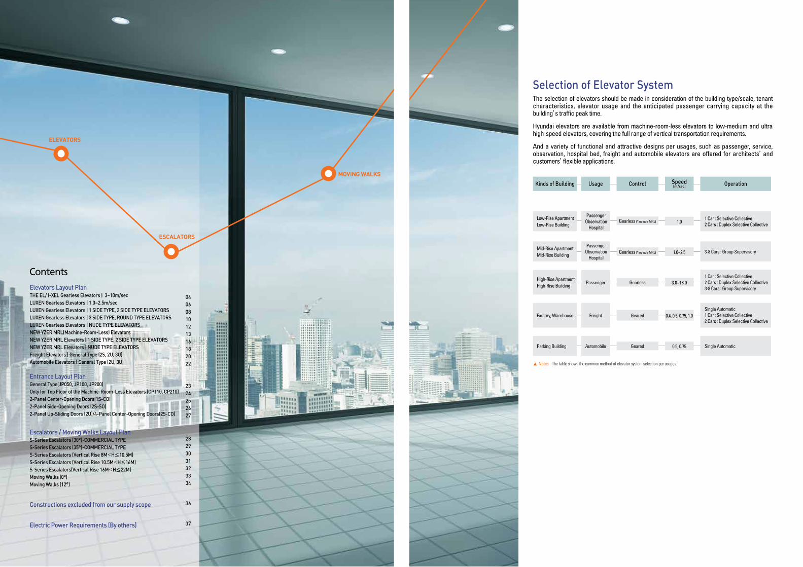
The selection of elevators should be made in consideration of the building type/scale, tenant characteristics, elevator usage and the anticipated passenger carrying capacity at the building’s traffic peak time.
Hyundai elevators are available from machine-room-less elevators to low-medium and ultra high-speed elevators, covering the full range of vertical transportation requirements.
And a variety of functional and attractive designs per usages, such as passenger, service, observation, hospital bed, freight and automobile elevators are offered for architects’and customers’flexible applications.
Selection of Elevator System
▲ Notes : The table shows the common method of elevator system selection per usages.
Kinds of Building OperationUsage Control Speed(m/sec)
1 Car : Selective Collective2 Cars : Duplex Selective Collective
Passenger Observation
Hospital
Low-Rise ApartmentLow-Rise Building
1.0Gearless (*include MRL)
3-8 Cars : Group Supervisory Passenger
Observation Hospital
Mid-Rise ApartmentMid-Rise Building Gearless (*include MRL) 1.0~2.5
Geared 0.4, 0.5, 0.75, 1.0Single Automatic1 Car : Selective Collective2 Cars : Duplex Selective Collective
FreightFactory, Warehouse
1 Car : Selective Collective2 Cars : Duplex Selective Collective3-8 Cars : Group Supervisory
Passenger Gearless 3.0~18.0 High-Rise ApartmentHigh-Rise Building
Single AutomaticAutomobile Geared 0.5, 0.75Parking Building
ELEvators
EscaLators
moving waLks
Elevators Layout Plan THE EL/ I-XEL Gearless Elevators | 3~10m/secLUXEN Gearless Elevators | 1.0~2.5m/secLUXEN Gearless Elevators | 1 SIDE TYPE, 2 SIDE TYPE ELEVATORSLUXEN Gearless Elevators | 3 SIDE TYPE, ROUND TYPE ELEVATORSLUXEN Gearless Elevators | NUDE TYPE ELEVATORSNEW YZER MRL(Machine-Room-Less) ElevatorsNEW YZER MRL Elevators | 1 SIDE TYPE, 2 SIDE TYPE ELEVATORSNEW YZER MRL Elevators | NUDE TYPE ELEVATORSFreight Elevators | General Type (2S, 2U, 3U)Automobile Elevators | General Type (2U, 3U)
Entrance Layout PlanGeneral Type(JP050, JP100, JP200)Only for Top Floor of the Machine-Room-Less Elevators (CP110, CP210)2-Panel Center-Opening Doors(1S-CO)2-Panel Side-Opening Doors (2S-SO)2-Panel Up-Sliding Doors (2U)/4-Panel Center-Opening Doors(2S-CO)
Escalators / Moving Walks Layout Plan S-Series Escalators (30°)-COMMERCIAL TYPES-Series Escalators (35°)-COMMERCIAL TYPES-Series Escalators (Vertical Rise 8M<H≤10.5M)S-Series Escalators (Vertical Rise 10.5M<H≤16M)S-Series Escalators(Vertical Rise 16M<H≤22M)Moving Walks (0°)Moving Walks (12°)
Constructions excluded from our supply scope
Electric Power Requirements (By others)
040608101213161820 22
2324252627
28293031323334
36
37
Contents
54
Plan of Hoistway & Machine Room (In-Line Arrangement of 3 Units)
Face-to-Face Arrangement
Section of Hoistway
MX3
R2 R2 R2
MX3X3
X1
X2
A
R1R1 R1
OP
CA
OP OP
OP OP OP
M.P
Min
. 200
Min
. 200
B YCB
MY
Y
Mac
hine
Roo
m
Acce
ss D
oor
(By o
ther
s)90
0 (W
) X 2
000
(H)
Dist
ribut
ion
Boar
d(B
y oth
ers)
Vent
Fan
(By o
ther
s)
Vent
Gril
le (B
y oth
ers)
Vent
Gril
le (B
y oth
ers)
Vent
Fan
(By o
ther
s)
Beam(By others)
Control Panel
Control Panel
MX2X2
X1 A
R1 R1
OP
CA
OP
R2 R2
CB
MY
YB
Machine Room Access Door (By others) 900 (W) X 2000 (H)
Distribution Board (By others)
Vent
Fan
(By o
ther
s)
Vent
Gril
le (B
y oth
ers)
Vent
Gril
le (B
y oth
ers)
Beam(By others)
C·P C·P C·PC·P C·P C·P
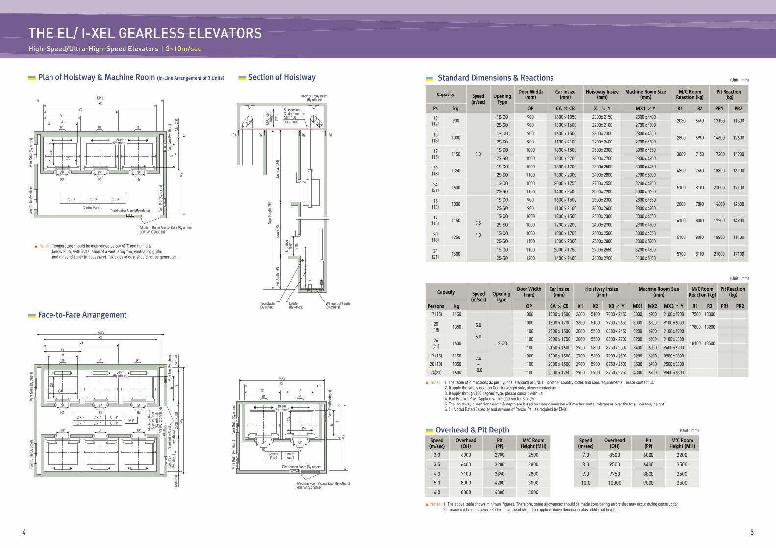
THE EL/ I-XEL GEARLESS ELEVATORS High-Speed/Ultra-High-Speed Elevators|3~10m/sec
Standard Dimensions & Reactions (Unit : mm)
3600
~ 4
000
Capacity Speed(m/sec)
OpeningType
Door Width (mm)
Car Insize(mm)
Hoistway Insize(mm)
Machine Room Size(mm)
M/C RoomReaction (kg)
Pit Reaction (kg)
Ps kg OP CA × CB X × Y MX1 × Y R1 R2 PR1 PR2
13(12) 900
3.0
1S-CO 900 1600 x 1350 2300 x 2150 2800 x 440012030 6650 13100 11300
2S-SO 900 1300 x 1600 2200 x 2100 2700 x 4300
15(13) 1000
1S-CO 900 1600 x 1500 2300 x 2300 2800 x 455012800 6950 14600 12600
2S-SO 900 1100 x 2100 2200 x 2600 2700 x 4800
17(15) 1150
1S-CO 1000 1800 x 1500 2500 x 2300 3000 x 455013080 7150 17200 14900
2S-SO 1000 1200 x 2200 2300 x 2700 2800 x 4900
20(18) 1350
1S-CO 1000 1800 x 1700 2500 x 2500 3000 x 475014350 7650 18800 16100
2S-SO 1100 1300 x 2300 2400 x 2800 2900 x 5000
24(21) 1600
1S-CO 1000 2000 x 1750 2700 x 2550 3200 x 480015100 8100 21000 17100
2S-SO 1100 1400 x 2400 2500 x 2900 3000 x 5100
15(13) 1000
3.5
4.0
1S-CO 900 1600 x 1500 2300 x 2300 2800 x 455012800 7800 14600 12600
2S-SO 900 1100 x 2100 2300 x 2600 2800 x 4800
17(15) 1150
1S-CO 1000 1800 x 1500 2500 x 2300 3000 x 455014100 8000 17200 14900
2S-SO 1000 1200 x 2200 2400 x 2700 2900 x 4900
20(18) 1350
1S-CO 1000 1800 x 1700 2500 x 2500 3000 x 475015100 8050 18800 16100
2S-SO 1100 1300 x 2300 2500 x 2800 3000 x 5000
24(21) 1600
1S-CO 1100 2000 x 1750 2700 x 2550 3200 x 480015700 8100 21000 17100
2S-SO 1200 1400 x 2400 2600 x 2900 3100 x 5100
(Unit : mm)
▲ Notes : 1. The table of dimensions as per Hyundai standard or EN81, For other country codes and spec requirements, Please contact us. 2. If apply the safety gear on Counterweight side, please contact us 3. If apply through(180 degree) type, please consult with us. 4. Rail Bracket Pitch Applied with 2,000mm for 3.0m/s 5. The Hoistway dimensions width & depth are based on clear dimension ±20mm horizontal tolerances over the total hoistway height 6. ( ): Noted Rated Capacity and number of Person(Ps), as required by EN81
Capacity Speed(m/sec)
OpeningType
Door Width (mm)
Car Insize(mm)
Hoistway Insize(mm)
Machine Room Size(mm)
M/C RoomReaction (kg)
Pit Reaction (kg)
Persons kg OP CA × CB X1 X2 X3 × Y MX1 MX2 MX3 × Y R1 R2 PR1 PR2
17 (15) 1150
5.0
6.01S-CO
1000 1800 x 1500 2600 5100 7800 x 2450 3000 6200 9100 x 5900 17500 13000
20(18) 1350
1000 1800 x 1700 2600 5100 7700 x 2650 3000 6200 9100 x 600017800 13200
1100 2000 x 1500 2800 5500 8300 x 2450 3200 6200 9100 x 5900
24(21) 1600
1100 2000 x 1750 2800 5500 8300 x 2700 3200 6500 9100 x 630018100 13500
1100 2150 x 1600 2950 5800 8750 x 2500 3400 6500 9400 x 6200
17 (15) 1150 7.0~
10.0
1000 1800 x 1500 2700 5400 7900 x 2500 3200 6400 8900 x 6000
20 (18) 1350 1100 2000 x 1500 2900 5900 8750 x 2500 3500 6700 9500 x 6300
24(21) 1600 1100 2000 x 1750 2900 5900 8750 x 2750 4300 6700 9500 x 6300
R1R2R2R1
Hook or Trolly Beam(By others)
SuspensionCinder ConcreteMin. 100(By others)
Receptacle (By others)
Ladder (By others)
Waterproof Finish (By others)
PR1 PR2
M/C
Roo
m
Heig
ht(M
H)Ov
erhe
ad (O
H)
Tota
l Hei
ght (
TH)
Trav
el (T
R)Pi
t Dep
th (P
P)
Entra
nce
Heig
ht
2100
X3
X2
X1
AR1R1R1
CA
OPOPOP
R2 R2 R2M
in. 2
00M
YYBCB
Control Panel
▲ Notes : Temperature should be maintained below 40°C and humidity below 90%, with installation of a ventilating fan, ventilating grille, and air conditioner (if necessary). Toxic gas or dust should not be generated.
Machine Room Access Door (By others) 900 (W) X 2000 (H)
Distribution Board (By others)
Vent
Fan
(By o
ther
s)
Vent
Gril
le (B
y oth
ers)
Vent
Gril
le (B
y oth
ers)
Vent
Fan
(By o
ther
s)
Beam(By others)
C·P C·P C·P
▲ Notes : 1. The above table shows minimum figures. Therefore, some allowances should be made considering errors that may occur during construction. 2. In case car height is over 2800mm, overhead should be applied above dimension plus additional height.
Speed(m/sec)
Overhead(OH)
Pit(PP)
M/C Room Height (MH)
3.0 6000 2700 2500
3.5 6400 3200 2800
4.0 7100 3850 2800
5.0 8000 4200 3000
6.0 8300 4300 3000
Speed(m/sec)
Overhead(OH)
Pit(PP)
M/C Room Height (MH)
7.0 8500 6000 3200
8.0 9500 6400 3500
9.0 9750 8800 3500
10.0 10000 9000 3500
(Unit : mm) Overhead & Pit Depth
76
Suspension Hook (By others)Cinder
Concrete Min. 100(By others)
R2 R1
PR1 PR2
Receptacle(By others)
Ladder(By others)
Waterproof Finish(By others)
M/C
Roo
mHe
ight
(MH)
Over
head
(OH)
Tota
l Hei
ght (
TH)
Trav
el (T
R)Pi
t Dep
th (P
P)
Ent.
Heig
ht (E
H)
2100
Plan of Hoistway & Machine Room Section of Hoistway
Machine Room Access Door (By others)Min. 900 (W)×2000 (H)
MX1
X1
A
R1
R2
OP
CA
B
CB
Y
MY
Vent
Gril
le (B
y oth
ers)
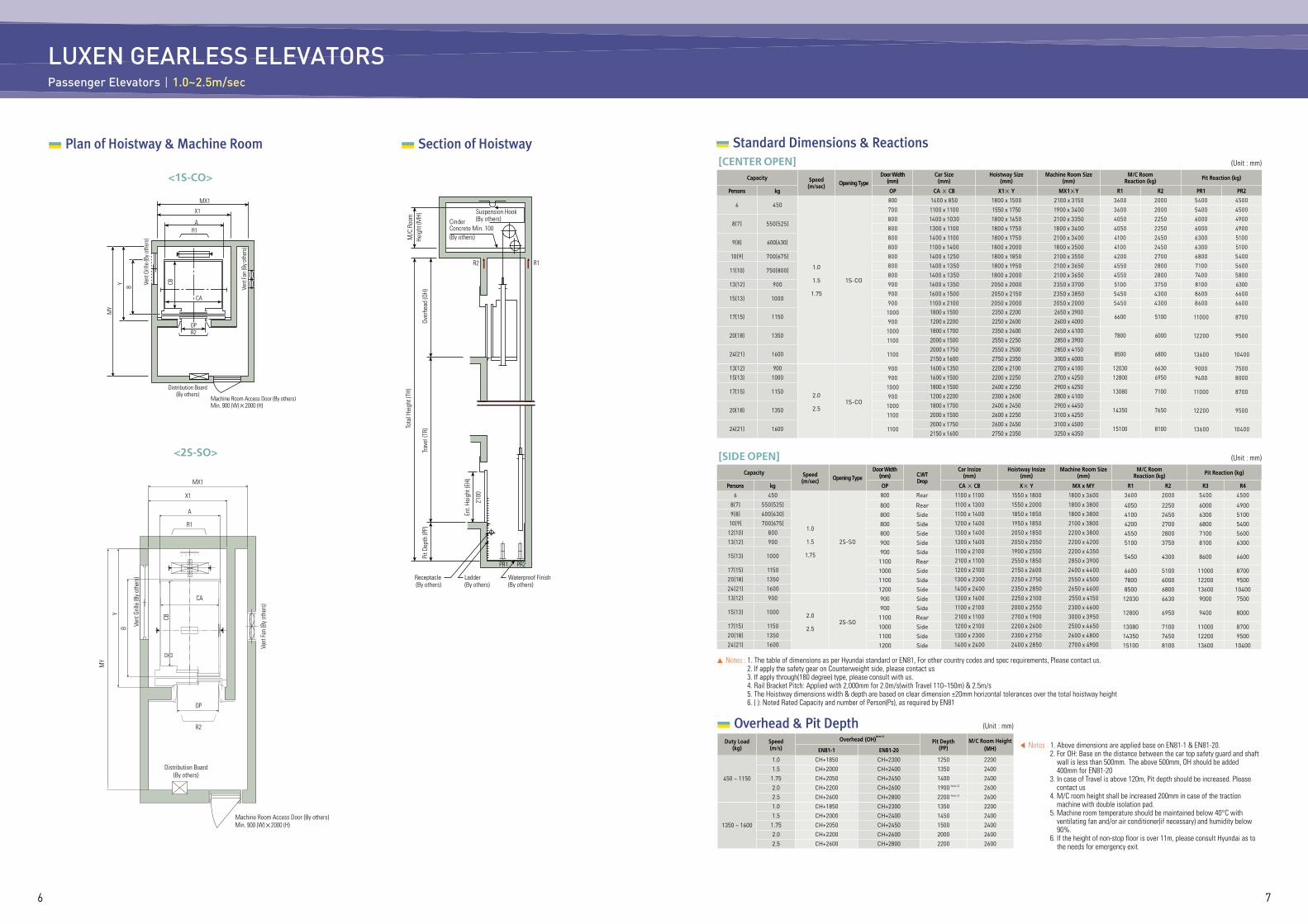
LUXEN GEARLESS ELEVATORSPassenger Elevators|1.0~2.5m/sec
Vent
Fan
(By o
ther
s)
Distribution Board(By others)
MX1
X1
AR1
OPR2
Distribution Board(By others)
Machine Room Access Door (By others)Min. 900 (W)×2000 (H)
CA
B
CB
Vent
Fan
(By o
ther
s)
Y
MY
Vent
Gril
le (B
y oth
ers)
Vent
Gril
le (B
y oth
ers)
Vent
Gril
le (B
y oth
ers)
Vent
Gril
le (B
y oth
ers)
Vent
Gril
le (B
y oth
ers)
Vent
Gril
le (B
y oth
ers)
Vent
Gril
le (B
y oth
ers)
Vent
Gril
le (B
y oth
ers)
Vent
Gril
le (B
y oth
ers)
Vent
Gril
le (B
y oth
ers)
Vent
Gril
le (B
y oth
ers)
Vent
Gril
le (B
y oth
ers)
Vent
Gril
le (B
y oth
ers)
Vent
Gril
le (B
y oth
ers)
Vent
Gril
le (B
y oth
ers)
Vent
Gril
le (B
y oth
ers)
Vent
Gril
le (B
y oth
ers)
Vent
Gril
le (B
y oth
ers)
Vent
Gril
le (B
y oth
ers)
Vent
Gril
le (B
y oth
ers)
Vent
Gril
le (B
y oth
ers)
Vent
Gril
le (B
y oth
ers)
Vent
Gril
le (B
y oth
ers)
Vent
Gril
le (B
y oth
ers)
Vent
Gril
le (B
y oth
ers)
Vent
Gril
le (B
y oth
ers)
Standard Dimensions & Reactions
<1S-CO>
<2S-SO>
(Unit : mm)
Capacity Speed(m/sec) Opening Type
Door Width(mm)
Car Size (mm)
Hoistway Size(mm)
Machine Room Size(mm)
M/C RoomReaction (kg) Pit Reaction (kg)
Persons kg OP CA × CB X1× Y MX1×Y R1 R2 PR1 PR2
6 450
1.0
1.5
1.75
1S-CO
800 1400 x 850 1800 x 1500 2100 x 3150 3600 2000 5400 4500
700 1100 x 1100 1550 x 1750 1900 x 3400 3600 2000 5400 4500
8(7) 550(525)800 1400 x 1030 1800 x 1650 2100 x 3350 4050 2250 6000 4900
800 1300 x 1100 1800 x 1750 1800 x 3400 4050 2250 6000 4900
9(8) 600(630)800 1400 x 1100 1800 x 1750 2100 x 3400 4100 2450 6300 5100
800 1100 x 1400 1800 x 2000 1800 x 3500 4100 2450 6300 5100
10(9) 700(675) 800 1400 x 1250 1800 x 1850 2100 x 3550 4200 2700 6800 5400
11(10) 750(800)800 1400 x 1350 1800 x 1950 2100 x 3650 4550 2800 7100 5600
800 1400 x 1350 1800 x 2000 2100 x 3650 4550 2800 7400 5800
13(12) 900 900 1600 x 1350 2050 x 2000 2350 x 3700 5100 3750 8100 6300
15(13) 1000900 1600 x 1500 2050 x 2150 2350 x 3850 5450 4300 8600 6600
900 1100 x 2100 2050 x 2000 2050 x 2000 5450 4300 8600 6600
17(15) 11501000 1800 x 1500 2350 x 2200 2650 x 3900
6600 5100 11000 8700900 1200 x 2200 2250 x 2600 2600 x 4000
20(18) 13501000 1800 x 1700 2350 x 2400 2650 x 4100
7800 6000 12200 95001100 2000 x 1500 2550 x 2250 2850 x 3900
24(21) 1600 11002000 x 1750 2550 x 2500 2850 x 4150
8500 6800 13600 104002150 x 1600 2750 x 2350 3000 x 4000
13(12) 900
2.0
2.51S-CO
900 1600 x 1350 2200 x 2100 2700 x 4100 12030 6630 9000 750015(13) 1000 900 1600 x 1500 2200 x 2250 2700 x 4250 12800 6950 9400 8000
17(15) 11501000 1800 x 1500 2400 x 2250 2900 x 4250
13080 7100 11000 8700900 1200 x 2200 2300 x 2600 2800 x 4100
20(18) 13501000 1800 x 1700 2400 x 2450 2900 x 4450
14350 7650 12200 95001100 2000 x 1500 2600 x 2250 3100 x 4250
24(21) 1600 11002000 x 1750 2600 x 2450 3100 x 4500
15100 8100 13600 104002150 x 1600 2750 x 2350 3250 x 4350
[CENTER OPEN]
▲ Notes : 1. The table of dimensions as per Hyundai standard or EN81, For other country codes and spec requirements, Please contact us. 2. If apply the safety gear on Counterweight side, please contact us 3. If apply through(180 degree) type, please consult with us. 4. Rail Bracket Pitch: Applied with 2,000mm for 2.0m/s(with Travel 110~150m) & 2.5m/s 5. The Hoistway dimensions width & depth are based on clear dimension ±20mm horizontal tolerances over the total hoistway height 6. ( ): Noted Rated Capacity and number of Person(Ps), as required by EN81
(Unit : mm)
Capacity Speed(m/sec) Opening Type
Door Width(mm) C.WT
Drop
Car Insize (mm)
Hoistway Insize(mm)
Machine Room Size(mm)
M/C RoomReaction (kg) Pit Reaction (kg)
Persons kg OP CA × CB X× Y MX x MY R1 R2 R3 R4
6 450
1.0
1.5
1.75
2S-SO
800 Rear 1100 x 1100 1550 x 1800 1800 x 3600 3600 2000 5400 4500
8(7) 550(525) 800 Rear 1100 x 1300 1550 x 2000 1800 x 3800 4050 2250 6000 49009(8) 600(630) 800 Side 1100 x 1400 1850 x 1850 1800 x 3800 4100 2450 6300 5100
10(9) 700(675) 800 Side 1200 x 1400 1950 x 1850 2100 x 3800 4200 2700 6800 540012(10) 800 800 Side 1300 x 1400 2050 x 1850 2200 x 3800 4550 2800 7100 560013(12) 900 900 Side 1300 x 1600 2050 x 2050 2200 x 4200 5100 3750 8100 6300
15(13) 1000900 Side 1100 x 2100 1900 x 2550 2200 x 4350
5450 4300 8600 66001100 Rear 2100 x 1100 2550 x 1850 2850 x 3900
17(15) 1150 1000 Side 1200 x 2100 2150 x 2600 2400 x 4400 6600 5100 11000 870020(18) 1350 1100 Side 1300 x 2300 2250 x 2750 2550 x 4500 7800 6000 12200 950024(21) 1600 1200 Side 1400 x 2400 2350 x 2850 2650 x 4600 8500 6800 13600 1040013(12) 900
2.0
2.52S-SO
900 Side 1300 x 1600 2250 x 2100 2550 x 4150 12030 6630 9000 7500
15(13) 1000900 Side 1100 x 2100 2000 x 2550 2300 x 4600
12800 6950 9400 80001100 Rear 2100 x 1100 2700 x 1900 3000 x 3950
17(15) 1150 1000 Side 1200 x 2100 2200 x 2600 2500 x 4650 13080 7100 11000 870020(18) 1350 1100 Side 1300 x 2300 2300 x 2750 2600 x 4800 14350 7650 12200 950024(21) 1600 1200 Side 1400 x 2400 2400 x 2850 2700 x 4900 15100 8100 13600 10400
[SIDE OPEN]
◀ Notes : 1. Above dimensions are applied base on EN81-1 & EN81-20. 2. For OH: Base on the distance between the car top safety guard and shaft
wall is less than 500mm. The above 500mm, OH should be added 400mm for EN81-20
3. In case of Travel is above 120m, Pit depth should be increased. Please contact us
4. M/C room height shall be increased 200mm in case of the traction machine with double isolation pad.
5. Machine room temperature should be maintained below 40°C with ventilating fan and/or air conditioner(if necessary) and humidity below 90%.
6. If the height of non-stop floor is over 11m, please consult Hyundai as to the needs for emergency exit.
Note 3)
Note 3)
Overhead & Pit DepthDuty Load
(kg)Speed(m/s)
Overhead (OH) Pit Depth(PP)
M/C Room Height(MH)EN81-1 EN81-20
450 ~ 1150
1.0 CH+1850 CH+2300 1250 2200
1.5 CH+2000 CH+2400 1350 2400
1.75 CH+2050 CH+2450 1400 2400
2.0 CH+2200 CH+2600 1900 2600
2.5 CH+2600 CH+2800 2200 2600
1350 ~ 1600
1.0 CH+1850 CH+2300 1350 2200
1.5 CH+2000 CH+2400 1450 2400
1.75 CH+2050 CH+2450 1500 2400
2.0 CH+2200 CH+2600 2000 2600
2.5 CH+2600 CH+2800 2200 2600
(Unit : mm)
Note 3)
Note 3)
Note 2)
98
Tota
l Hei
ght (
TH)
Over
head
(OH)
Glas
s Enc
losu
re (B
y oth
ers)
Trav
el (T
R)Pi
t Dep
th (P
P)
Ent. H
eight
(EH)
2100
Conc
rete
(Min
. 360
0) o
rGl
ass E
nclo
sure
(By o
ther
s)
M/C
Roo
mHe
ight
(MH)
Suspension Hook (By others)
CinderConcreteMin. 100(By others)
Min.500
Receptacle(By others)
Ladder(By others)
PR1PR2
Maintenance Deck(By others)
Waterproof Finish(By others)
MX
Y
Vent
Gril
le (B
y oth
ers)
Vent
Gril
le (B
y oth
ers)
B
MY
R1
CB
R2R2
Glass Wall(By others)
Glass Wall(By others)
Distribution Board(By others)
Distribution Board(By others)
Mac
hine
Roo
mAc
cess
Doo
r (By
oth
ers)
Min
. 900
(W)×
2000
(H)
Mac
hine
Roo
mAc
cess
Doo
r (By
oth
ers)
Min
. 900
(W)×
2000
(H)
ControlPanel
ControlPanel
XA
MXX
A
CA
Y B
MY
R1
CBCA
OP
OP
▲ Notes : Machine room temperature should be maintained below 40°C with ventilating fan and/or air conditioner (if necessary) and humidity below 90%.
Vent
Fan
(By o
ther
s)Ve
nt Fa
n (B
y oth
ers)
Plan of Hoistway & Machine Room Section of Hoistway Standard Dimensions & Reactions (Unit : mm)
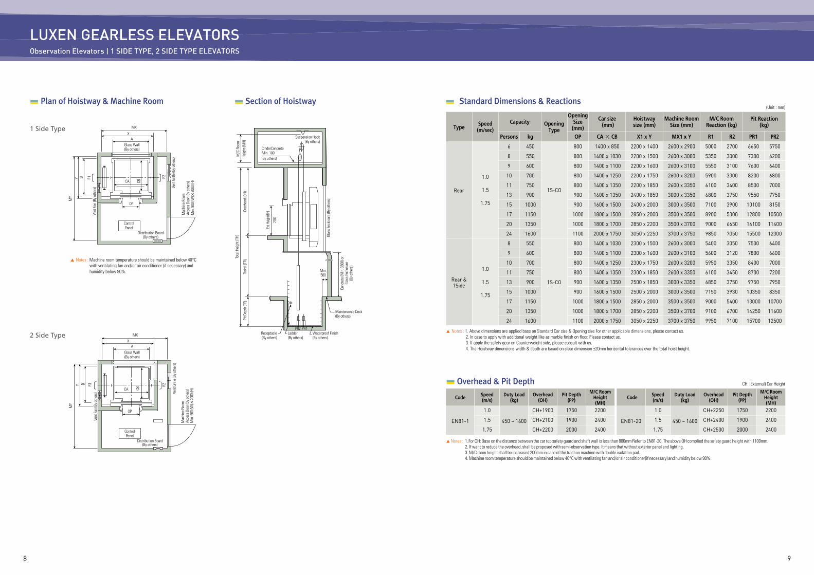
LUXEN GEARLESS ELEVATORSObservation Elevators | 1 SIDE TYPE, 2 SIDE TYPE ELEVATORS
1 Side Type
2 Side Type▲ Notes : 1. Above dimensions are applied base on Standard Car size & Opening size For other applicable dimensions, please contact us. 2. In case to apply with additional weight like as marble finish on floor, Please contact us. 3. If apply the safety gear on Counterweight side, please consult with us. 4. The Hoistway dimensions width & depth are based on clear dimension ±20mm horizontal tolerances over the total hoist height.
TypeSpeed(m/sec)
Capacity OpeningType
OpeningSize (mm)
Car size (mm)
Hoistwaysize (mm)
Machine Room Size (mm)
M/C RoomReaction (kg)
Pit Reaction(kg)
Persons kg OP CA × CB X1 x Y MX1 x Y R1 R2 PR1 PR2
Rear
1.0
1.5
1.75
6 450
1S-CO
800 1400 x 850 2200 x 1400 2600 x 2900 5000 2700 6650 5750
8 550 800 1400 x 1030 2200 x 1500 2600 x 3000 5350 3000 7300 6200
9 600 800 1400 x 1100 2200 x 1600 2600 x 3100 5550 3100 7600 6400
10 700 800 1400 x 1250 2200 x 1750 2600 x 3200 5900 3300 8200 6800
11 750 800 1400 x 1350 2200 x 1850 2600 x 3350 6100 3400 8500 7000
13 900 900 1600 x 1350 2400 x 1850 3000 x 3350 6800 3750 9550 7750
15 1000 900 1600 x 1500 2400 x 2000 3000 x 3500 7100 3900 10100 8150
17 1150 1000 1800 x 1500 2850 x 2000 3500 x 3500 8900 5300 12800 10500
20 1350 1000 1800 x 1700 2850 x 2200 3500 x 3700 9000 6650 14100 11400
24 1600 1100 2000 x 1750 3050 x 2250 3700 x 3750 9850 7050 15500 12300
Rear & 1Side
1.0
1.5
1.75
8 550
1S-CO
800 1400 x 1030 2300 x 1500 2600 x 3000 5400 3050 7500 6400
9 600 800 1400 x 1100 2300 x 1600 2600 x 3100 5600 3120 7800 6600
10 700 800 1400 x 1250 2300 x 1750 2600 x 3200 5950 3350 8400 7000
11 750 800 1400 x 1350 2300 x 1850 2600 x 3350 6100 3450 8700 7200
13 900 900 1600 x 1350 2500 x 1850 3000 x 3350 6850 3750 9750 7950
15 1000 900 1600 x 1500 2500 x 2000 3000 x 3500 7150 3930 10350 8350
17 1150 1000 1800 x 1500 2850 x 2000 3500 x 3500 9000 5400 13000 10700
20 1350 1000 1800 x 1700 2850 x 2200 3500 x 3700 9100 6700 14250 11600
24 1600 1100 2000 x 1750 3050 x 2250 3700 x 3750 9950 7100 15700 12500
▲ Notes : 1. For OH: Base on the distance between the car top safety guard and shaft wall is less than 800mm Refer to EN81-20, The above OH complied the safety guard height with 1100mm. 2. If want to reduce the overhead, shall be proposed with semi-observation type. It means that without exterior panel and lighting. 3. M/C room height shall be increased 200mm in case of the traction machine with double isolation pad. 4. Machine room temperature should be maintained below 40°C with ventilating fan and/or air conditioner(if necessary) and humidity below 90%.
Code Speed(m/s)
Duty Load(kg)
Overhead(OH)
Pit Depth(PP)
M/C Room Height(MH)
EN81-1
1.0
450 ~ 1600
CH+1900 1750 2200
1.5 CH+2100 1900 2400
1.75 CH+2200 2000 2400
Code Speed(m/s)
Duty Load(kg)
Overhead(OH)
Pit Depth(PP)
M/C Room Height(MH)
EN81-20
1.0
450 ~ 1600
CH+2250 1750 2200
1.5 CH+2400 1900 2400
1.75 CH+2500 2000 2400
CH: (External) Car Height Overhead & Pit Depth
1110
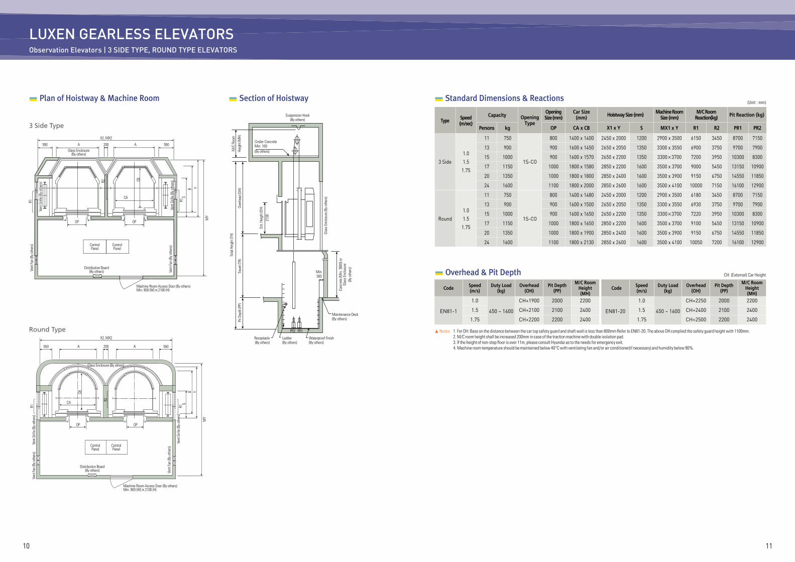
LUXEN GEARLESS ELEVATORSObservation Elevators | 3 SIDE TYPE, ROUND TYPE ELEVATORS
Section of Hoistway Plan of Hoistway & Machine Room
MY
X2, MX2
550A200A550Glass Enclosure
(By others)
Vent
Gril
le (B
y oth
ers)
Vent
Gril
le (B
y oth
ers)
R1S
B Y
CBR2
Vent
Fan
(By o
ther
s)
Vent
Fan
(By o
ther
s)
CA
OP OP
ControlPanel
ControlPanel
Distribution Board(By others)
Machine Room Access Door (By others)Min. 900 (W)×2100 (H)
R1
3 Side Type
X2, MX2
550A200A550
Glass Enclosure (By others)
Vent
Gril
le (B
y oth
ers)
Vent
Gril
le (B
y oth
ers)
SB
R2
R1 R1
Y
MY
CB
Vent
Fan
(By o
ther
s)
Vent
Fan
(By o
ther
s)
CA
OP OP
ControlPanel
ControlPanel
Distribution Board(By others)
Machine Room Access Door (By others)Min. 900 (W)×2100 (H)
Round Type
Tota
l Hei
ght (
TH)
Over
head
(OH)
Glas
s Enc
losu
re (B
y oth
ers)
Trav
el (T
R)Pi
t Dep
th (P
P)
Ent.
Heig
ht (E
H)21
00
Conc
rete
(Min
. 360
0) o
rGl
ass E
nclo
sure
(By o
ther
s)
M/C
Roo
mHe
ight
(MH)
Cinder ConcreteMin. 100(By others)
Suspension Hook (By others)
Min.500
Receptacle(By others)
Ladder(By others)
Waterproof Finish(By others)
Maintenance Deck(By others)
PR2 PR1
(Unit : mm) Standard Dimensions & Reactions
Type Speed(m/sec)
Capacity OpeningType
OpeningSize (mm)
Car Size(mm) Hoistway Size (mm) Machine Room
Size (mm)M/C Room
Reaction(kg) Pit Reaction (kg)
Persons kg OP CA x CB X1 x Y S MX1 x Y R1 R2 PR1 PR2
3 Side
1.0
1.5
1.75
11 750
1S-CO
800 1400 x 1400 2450 x 2000 1200 2900 x 3500 6150 3450 8700 7150
13 900 900 1600 x 1450 2650 x 2050 1350 3300 x 3550 6900 3750 9700 7900
15 1000 900 1600 x 1570 2650 x 2200 1350 3300×3700 7200 3950 10300 8300
17 1150 1000 1800 x 1580 2850 x 2200 1600 3500 x 3700 9000 5450 13150 10900
20 1350 1000 1800 x 1800 2850 x 2400 1600 3500 x 3900 9150 6750 14550 11850
24 1600 1100 1800 x 2000 2850 x 2600 1600 3500 x 4100 10000 7150 16100 12900
Round
1.0
1.5
1.75
11 750
1S-CO
800 1400 x 1480 2450 x 2000 1200 2900 x 3500 6180 3450 8700 7150
13 900 900 1600 x 1500 2650 x 2050 1350 3300 x 3550 6930 3750 9700 7900
15 1000 900 1600 x 1650 2650 x 2200 1350 3300×3700 7220 3950 10300 8300
17 1150 1000 1800 x 1650 2850 x 2200 1600 3500 x 3700 9100 5450 13150 10900
20 1350 1000 1800 x 1900 2850 x 2400 1600 3500 x 3900 9150 6750 14550 11850
24 1600 1100 1800 x 2130 2850 x 2600 1600 3500 x 4100 10050 7200 16100 12900
▲ Notes : 1. For OH: Base on the distance between the car top safety guard and shaft wall is less than 800mm Refer to EN81-20, The above OH complied the safety guard height with 1100mm. 2. M/C room height shall be increased 200mm in case of the traction machine with double isolation pad. 3. If the height of non-stop floor is over 11m, please consult Hyundai as to the needs for emergency exit. 4. Machine room temperature should be maintained below 40°C with ventilating fan and/or air conditioner(if necessary) and humidity below 90%.
Code Speed(m/s)
Duty Load(kg)
Overhead(OH)
Pit Depth(PP)
M/C Room Height(MH)
EN81-1
1.0
450 ~ 1600
CH+1900 2000 2200
1.5 CH+2100 2100 2400
1.75 CH+2200 2200 2400
Code Speed(m/s)
Duty Load(kg)
Overhead(OH)
Pit Depth(PP)
M/C Room Height(MH)
EN81-20
1.0
450 ~ 1600
CH+2250 2000 2200
1.5 CH+2400 2100 2400
1.75 CH+2500 2200 2400
CH: (External) Car Height Overhead & Pit Depth
1312
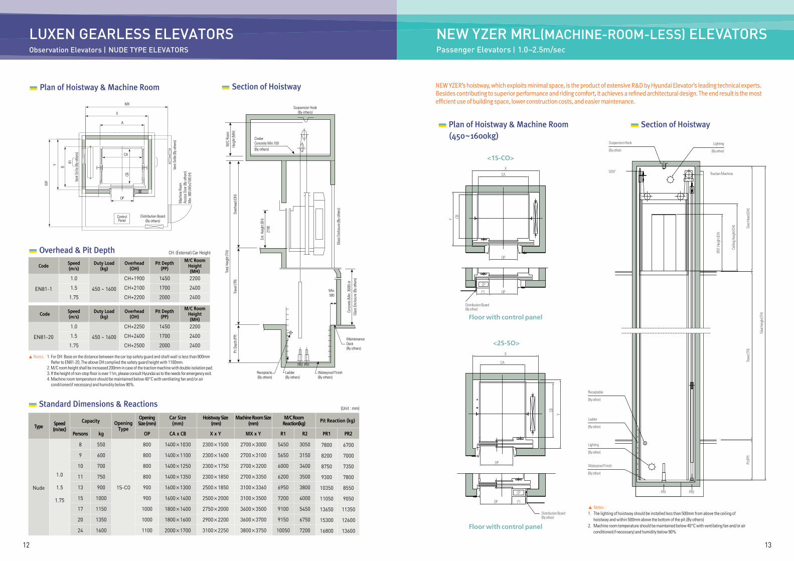
LUXEN GEARLESS ELEVATORSObservation Elevators | NUDE TYPE ELEVATORS
Plan of Hoistway & Machine Room
MY
Y B
OP
A
X
MX
ControlPanel
Distribution Board(By others)
Vent
Gril
le (B
y oth
ers)
Vent
Gril
le (B
y oth
ers)
Mac
hine
Roo
mAc
cess
Doo
r (By
oth
ers)
Min
. 900
(W)×
2100
(H)
R1
CB
CA
Section of Hoistway
Suspension Hook(By others)
Min.500
Receptacle(By others)
Ladder(By others)
Waterproof Finish(By others)
Maintenance Deck(By others)
PR2 PR1
CinderConcrete Min.100(By others)
M/C
Roo
mHe
ight
(MH)
Tota
l Hei
ght (
TH)
Over
head
(OH)
Glas
s Enc
losu
re (B
y oth
ers)
Conc
rete
(Min
. 360
0) o
rGl
ass E
nclo
sure
(By o
ther
s)
Ent.
Heig
ht (E
H)21
00
Trav
el (T
R)Pi
t Dep
th (P
P)
(Unit : mm) Standard Dimensions & Reactions
Type Speed(m/sec)
Capacity OpeningType
OpeningSize (mm)
Car Size(mm)
Hoistway Size (mm)
Machine Room Size (mm)
M/C Room Reaction(kg) Pit Reaction (kg)
Persons kg OP CA x CB X x Y MX x Y R1 R2 PR1 PR2
Nude
1.0
1.5
1.75
8 550
1S-CO
800 1400×1030 2300×1500 2700×3000 5450 3050 7800 6700
9 600 800 1400×1100 2300×1600 2700×3100 5650 3150 8200 7000
10 700 800 1400×1250 2300×1750 2700×3200 6000 3400 8750 7350
11 750 800 1400×1350 2300×1850 2700×3350 6200 3500 9300 7800
13 900 900 1600×1300 2500×1850 3100×3360 6950 3800 10350 8550
15 1000 900 1600×1400 2500×2000 3100×3500 7200 4000 11050 9050
17 1150 1000 1800×1400 2750×2000 3600×3500 9100 5450 13650 11350
20 1350 1000 1800×1600 2900×2200 3600×3700 9150 6750 15300 12600
24 1600 1100 2000×1700 3100×2250 3800×3750 10050 7200 16800 13600
▲ Notes : 1. For OH: Base on the distance between the car top safety guard and shaft wall is less than 800mm Refer to EN81-20, The above OH complied the safety guard height with 1100mm.
2. M/C room height shall be increased 200mm in case of the traction machine with double isolation pad. 3. If the height of non-stop floor is over 11m, please consult Hyundai as to the needs for emergency exit. 4. Machine room temperature should be maintained below 40°C with ventilating fan and/or air
conditioner(if necessary) and humidity below 90%.
Code Speed(m/s)
Duty Load(kg)
Overhead(OH)
Pit Depth(PP)
M/C Room Height(MH)
EN81-1
1.0
450 ~ 1600
CH+1900 1450 2200
1.5 CH+2100 1700 2400
1.75 CH+2200 2000 2400
Code Speed(m/s)
Duty Load(kg)
Overhead(OH)
Pit Depth(PP)
M/C Room Height(MH)
EN81-20
1.0
450 ~ 1600
CH+2250 1450 2200
1.5 CH+2400 1700 2400
1.75 CH+2500 2000 2400
CH: (External) Car Height Overhead & Pit Depth
NEW YZER MRL(MACHINE-ROOM-LESS) ELEVATORSPassenger Elevators | 1.0~2.5m/sec
NEW YZER’s hoistway, which exploits minimal space, is the product of extensive R&D by Hyundai Elevator’s leading technical experts.Besides contributing to superior performance and riding comfort, it achieves a refined architectural design. The end result is the mostefficient use of building space, lower construction costs, and easier maintenance.
▲ Notes :1. The lighting of hoistway should be installed less than 500mm from above the ceiling of hoistway and within 500mm above the bottom of the pit.(By others)2. Machine room temperature should be maintained below 40°C with ventilating fan and/or air conditioner(if necessary) and humidity below 90%
Plan of Hoistway & Machine Room (450~1600kg)
Section of Hoistway
Receptable
Suspension Hook Lighting
ENT.
Heig
ht (E
H)
Ceilin
g Hei
ght (C
H) Over
Hea
d (OH
)Tra
vel (T
R)
Tota
l Hei
ght (T
H)
Pit (P
P)
Traction Machine
Ladder
Lighting
Waterproof Finish
PR1 PR2
(By other)
(By other)
GOV'
(By other)
(By other)
(By other)
(By other)
Floor with control panel
Distribution Board(By other)
OP (*)
CP
X
CA
OP
CB
Y
Floor with control panel
Distribution Board(By other)
OP(*)
CP
OP
XCA
CBY
<1S-CO>
<2S-SO>
1514
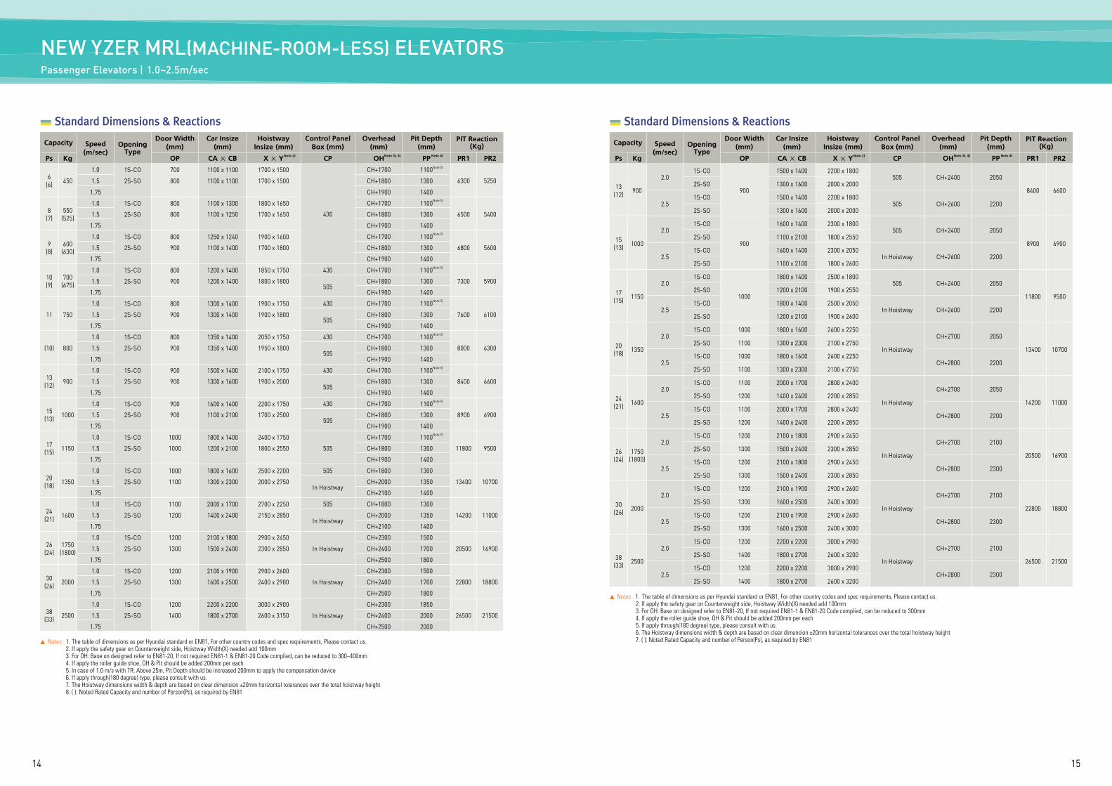
▲ Notes : 1. The table of dimensions as per Hyundai standard or EN81, For other country codes and spec requirements, Please contact us. 2. If apply the safety gear on Counterweight side, Hoistway Width(X) needed add 100mm 3. For OH: Base on designed refer to EN81-20, If not required EN81-1 & EN81-20 Code complied, can be reduced to 300~400mm 4. If apply the roller guide shoe, OH & Pit should be added 200mm per each 5. In case of 1.0 m/s with TR: Above 25m, Pit Depth should be increased 200mm to apply the compensation device 6. If apply through(180 degree) type, please consult with us. 7. The Hoistway dimensions width & depth are based on clear dimension ±20mm horizontal tolerances over the total hoistway height 8. ( ): Noted Rated Capacity and number of Person(Ps), as required by EN81
Standard Dimensions & Reactions
Capacity Speed(m/sec)
OpeningType
Door Width(mm)
Car Insize(mm)
HoistwayInsize (mm)
Control Panel Box (mm)
Overhead(mm)
Pit Depth (mm)
PIT Reaction (Kg)
Ps Kg OP CA × CB X × Y CP OH PP PR1 PR2
6(6) 450
1.0 1S-CO 700 1100 x 1100 1700 x 1500
430
CH+1700 1100
6300 52501.5 2S-SO 800 1100 x 1100 1700 x 1500 CH+1800 1300
1.75 CH+1900 1400
8(7)
550(525)
1.0 1S-CO 800 1100 x 1300 1800 x 1650 CH+1700 1100
6500 54001.5 2S-SO 800 1100 x 1250 1700 x 1650 CH+1800 1300
1.75 CH+1900 1400
9(8)
600(630)
1.0 1S-CO 800 1250 x 1240 1900 x 1600 CH+1700 1100
6800 56001.5 2S-SO 900 1100 x 1400 1700 x 1800 CH+1800 1300
1.75 CH+1900 1400
10(9)
700(675)
1.0 1S-CO 800 1200 x 1400 1850 x 1750 430 CH+1700 1100
7300 59001.5 2S-SO 900 1200 x 1400 1800 x 1800505
CH+1800 1300
1.75 CH+1900 1400
11 750
1.0 1S-CO 800 1300 x 1400 1900 x 1750 430 CH+1700 1100
7600 61001.5 2S-SO 900 1300 x 1400 1900 x 1800505
CH+1800 1300
1.75 CH+1900 1400
(10) 800
1.0 1S-CO 800 1350 x 1400 2050 x 1750 430 CH+1700 1100
8000 63001.5 2S-SO 900 1350 x 1400 1950 x 1800505
CH+1800 1300
1.75 CH+1900 1400
13(12) 900
1.0 1S-CO 900 1500 x 1400 2100 x 1750 430 CH+1700 1100
8400 66001.5 2S-SO 900 1300 x 1600 1900 x 2000505
CH+1800 1300
1.75 CH+1900 1400
15(13) 1000
1.0 1S-CO 900 1600 x 1400 2200 x 1750 430 CH+1700 1100
8900 69001.5 2S-SO 900 1100 x 2100 1700 x 2500505
CH+1800 1300
1.75 CH+1900 1400
17(15) 1150
1.0 1S-CO 1000 1800 x 1400 2400 x 1750
505
CH+1700 1100
11800 95001.5 2S-SO 1000 1200 x 2100 1800 x 2550 CH+1800 1300
1.75 CH+1900 1400
20(18) 1350
1.0 1S-CO 1000 1800 x 1600 2500 x 2200 505 CH+1800 1300
13400 107001.5 2S-SO 1100 1300 x 2300 2000 x 2750In Hoistway
CH+2000 1350
1.75 CH+2100 1400
24(21) 1600
1.0 1S-CO 1100 2000 x 1700 2700 x 2250 505 CH+1800 1300
14200 110001.5 2S-SO 1200 1400 x 2400 2150 x 2850In Hoistway
CH+2000 1350
1.75 CH+2100 1400
26(24)
1750(1800)
1.0 1S-CO 1200 2100 x 1800 2900 x 2450
In Hoistway
CH+2300 1500
20500 169001.5 2S-SO 1300 1500 x 2400 2300 x 2850 CH+2400 1700
1.75 CH+2500 1800
30(26) 2000
1.0 1S-CO 1200 2100 x 1900 2900 x 2600
In Hoistway
CH+2300 1500
22800 188001.5 2S-SO 1300 1600 x 2500 2400 x 2900 CH+2400 1700
1.75 CH+2500 1800
38(33) 2500
1.0 1S-CO 1200 2200 x 2200 3000 x 2900
In Hoistway
CH+2300 1850
26500 215001.5 2S-SO 1400 1800 x 2700 2600 x 3150 CH+2400 2000
1.75 CH+2500 2000
Note 5)
Note 5)
Note 5)
Note 5)
Note 5)
Note 5)
Note 5)
Note 5)
Note 5)
Note 2) Note 3), 4) Note 4)
NEW YZER MRL(MACHINE-ROOM-LESS) ELEVATORSPassenger Elevators | 1.0~2.5m/sec
Standard Dimensions & Reactions
Capacity Speed(m/sec)
OpeningType
Door Width(mm)
Car Insize(mm)
HoistwayInsize (mm)
Control Panel Box (mm)
Overhead(mm)
Pit Depth (mm)
PIT Reaction (Kg)
Ps Kg OP CA × CB X × Y CP OH PP PR1 PR2
13(12) 900
2.01S-CO
900
1500 x 1400 2200 x 1800505 CH+2400 2050
8400 66002S-SO 1300 x 1600 2000 x 2000
2.51S-CO 1500 x 1400 2200 x 1800
505 CH+2600 22002S-SO 1300 x 1600 2000 x 2000
15(13) 1000
2.01S-CO
900
1600 x 1400 2300 x 1800505 CH+2400 2050
8900 69002S-SO 1100 x 2100 1800 x 2550
2.51S-CO 1600 x 1400 2300 x 2050
In Hoistway CH+2600 22002S-SO 1100 x 2100 1800 x 2600
17(15) 1150
2.01S-CO
1000
1800 x 1400 2500 x 1800505 CH+2400 2050
11800 95002S-SO 1200 x 2100 1900 x 2550
2.51S-CO 1800 x 1400 2500 x 2050
In Hoistway CH+2600 22002S-SO 1200 x 2100 1900 x 2600
20(18) 1350
2.01S-CO 1000 1800 x 1600 2600 x 2250
In Hoistway
CH+2700 2050
13400 107002S-SO 1100 1300 x 2300 2100 x 2750
2.51S-CO 1000 1800 x 1600 2600 x 2250
CH+2800 22002S-SO 1100 1300 x 2300 2100 x 2750
24(21) 1600
2.01S-CO 1100 2000 x 1700 2800 x 2400
In Hoistway
CH+2700 2050
14200 110002S-SO 1200 1400 x 2400 2200 x 2850
2.51S-CO 1100 2000 x 1700 2800 x 2400
CH+2800 22002S-SO 1200 1400 x 2400 2200 x 2850
26(24)
1750(1800)
2.01S-CO 1200 2100 x 1800 2900 x 2450
In Hoistway
CH+2700 2100
20500 169002S-SO 1300 1500 x 2400 2300 x 2850
2.51S-CO 1200 2100 x 1800 2900 x 2450
CH+2800 23002S-SO 1300 1500 x 2400 2300 x 2850
30(26) 2000
2.01S-CO 1200 2100 x 1900 2900 x 2600
In Hoistway
CH+2700 2100
22800 188002S-SO 1300 1600 x 2500 2400 x 3000
2.51S-CO 1200 2100 x 1900 2900 x 2600
CH+2800 23002S-SO 1300 1600 x 2500 2400 x 3000
38(33) 2500
2.01S-CO 1200 2200 x 2200 3000 x 2900
In Hoistway
CH+2700 2100
26500 215002S-SO 1400 1800 x 2700 2600 x 3200
2.51S-CO 1200 2200 x 2200 3000 x 2900
CH+2800 23002S-SO 1400 1800 x 2700 2600 x 3200
Note 2) Note 3), 4) Note 4)
▲ Notes : 1. The table of dimensions as per Hyundai standard or EN81, For other country codes and spec requirements, Please contact us. 2. If apply the safety gear on Counterweight side, Hoistway Width(X) needed add 100mm 3. For OH: Base on designed refer to EN81-20, If not required EN81-1 & EN81-20 Code complied, can be reduced to 300mm 4. If apply the roller guide shoe, OH & Pit should be added 200mm per each 5. If apply through(180 degree) type, please consult with us. 6. The Hoistway dimensions width & depth are based on clear dimension ±20mm horizontal tolerances over the total hoistway height 7. ( ): Noted Rated Capacity and number of Person(Ps), as required by EN81
1716
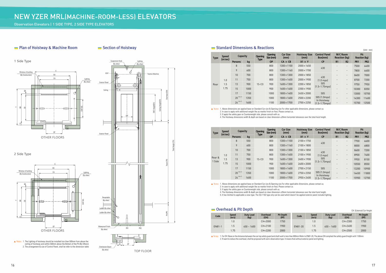
NEW YZER MRL(MACHINE-ROOM-LESS) ELEVATORS Observation Elevators | 1 SIDE TYPE, 2 SIDE TYPE ELEVATORS
Standard Dimensions & Reactions (Unit : mm)
Plan of Hoistway & Machine Room
OTHER FLOORS
X
Y
15BB CB
CWT
BG.
80
Window of building(By Construction)
Lighting(By other)
AA
CA
OP
1 Side Type
OTHER FLOORS
X
Y
15BB CB
CWT
BG.
80
Window of building(By Construction)
Lighting(By other)
AA
CA
OP
2 Side Type
▲ Notes : 1. The Lighting of hoistway should be installed lsss than 500mm from above the ceiling of hoistway and within 500mm above the Bottom of the Pit (By Others)
2. The arrangement & size of Control Panel, shall be refer to the dimension table
Section of Hoistway
Lighting(By other)
Suspension Hook(By other)
GOV’
O P
Traction Machine
ENT.
Heig
ht(E
H)
Ceili
ng H
eigh
t(CH) Ov
erhe
ad (O
H)Tr
avel
(TR)
Pit (
PP)
Tota
l Hei
ght (
TH)
Exterior Panel
Exterior Panel
Receptable(By other)
Waterproof Finish(By other)
Distribution Board(By other)
PR1
CP(X) OP
PR2
Ladder (By other)
Ladder (By other)
Ceiling
Type Speed(m/sec)
Capacity OpeningType
OpeningSize (mm)
Car Size(mm)
Hoistway Size(mm)
Control PanelBox(mm)
M/C RoomReaction (kg)
PitReaction (kg)
Persons kg OP CA × CB X1 × Y CP R1 R2 PR1 PR2
Rear
1.0
1.5
1.75
8 550
1S-CO
800 1300×1100 2000×1650430
- - 7500 6400
9 600 800 1300×1160 2000×1700 - - 7800 6600
10 700 800 1300×1300 2000×1850430
(1.0 mps)505
(1.5~1.75mps)
- - 8400 7000
11 750 800 1300×1400 2000×1900 - - 8700 7200
13 900 900 1600×1300 2200×1850 - - 9750 7950
15 1000 900 1600×1400 2200×1900 - - 10300 8350
17 1150 1000 1800×1400 2450×2000 505 - - 13000 10700
20 1350 1000 1800×1600 2500×2200 505 (1.0mps)In Hoistway
(1.5~1.75mps)
- - 14300 11600
24 1600 1100 2000×1700 2700×2250 - - 15700 12500
Note 2)
Note 2)
▲ Notes : 1. Above dimensions are applied base on Standard Car size & Opening size For other applicable dimensions, please contact us. 2. In case to apply with additional weight like as marble finish on floor, Please contact us. 3. If apply the safety gear on Counterweight side, please consult with us. 4. The Hoistway dimensions width & depth are based on clear dimension ±20mm horizontal tolerances over the total hoist height.
Type Speed(m/sec)
Capacity OpeningType
OpeningSize (mm)
Car Size(mm)
Hoistway Size(mm)
Control PanelBox(mm)
M/C RoomReaction (kg)
PitReaction (kg)
Persons kg OP CA × CB X1 × Y CP R1 R2 PR1 PR2
Rear &1 Side
1.0
1.5
1.75
8 550
1S-CO
800 1300×1100 2100×1750430
- - 7700 6600
9 600 800 1300×1160 2100×1800 - - 8000 6800
10 700 800 1300×1300 2100×1850430
(1.0 mps)505
(1.5~1.75mps)
- - 8600 7200
11 750 800 1300×1400 2100×1900 - - 8900 7400
13 900 900 1600×1300 2400×1900 - - 9950 8150
15 1000 900 1600×1400 2400×2000 - - 10550 8550
17 1150 1000 1800×1400 2700×2150 505 - - 13200 10900
20 1350 1000 1800×1600 2750×2350 505 (1.0mps)In Hoistway
(1.5~1.75mps)
- - 14450 11800
24 1600 1100 2000×1700 2950×2400 - - 15900 12700
Note 2)
Note 2)
▲ Notes : 1. Above dimensions are applied base on Standard Car size & Opening size For other applicable dimensions, please contact us. 2. In case to apply with additional weight like as marble finish on floor, Please contact us. 3. If apply the safety gear on Counterweight side, please consult with us. 4. The Hoistway dimensions width & depth are based on clear dimension ±20mm horizontal tolerances over the total hoist height. 5. It has limitted to applicable a view type. The SQ-119Z type only can be used which doesn't be applied exterior panel included lighting.
▲ Notes : 1. For OH: Base on the distance between the car top safety guard and shaft wall is less than 800mm Refer to EN81-20, The above OH complied the safety guard height with 1100mm. 2. If want to reduce the overhead, shall be proposed with semi-observation type. It means that without exterior panel and lighting.
Code Speed(m/s)
Duty Load(kg)
Overhead(OH)
Pit Depth(PP)
EN81-1
1.0
450 ~ 1600
CH+2000 1750
1.5 CH+2100 1900
1.75 CH+2200 2000
Code Speed(m/s)
Duty Load(kg)
Overhead(OH)
Pit Depth(PP)
EN81-20
1.0
450 ~ 1600
CH+2300 1750
1.5 CH+2400 1900
1.75 CH+2500 2000
CH: (External) Car Height Overhead & Pit Depth
TOP FLOOR
1918
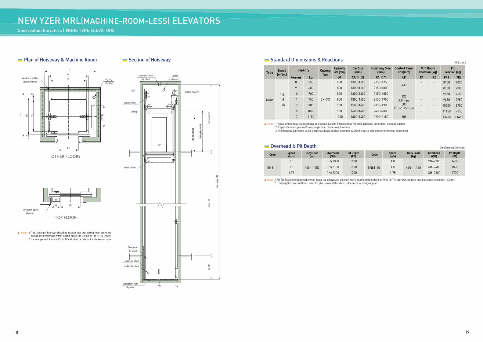
NEW YZER MRL(MACHINE-ROOM-LESS) ELEVATORSObservation Elevators | NUDE TYPE ELEVATORS
Standard Dimensions & Reactions (Unit : mm)
Plan of Hoistway & Machine Room
X
Y
15BB CB
CWT
BG.
80
Window of building(By Construction)
Distribution Board(By other)
CP
(X) OP
Lighting(By other)
AA
CA
OP
▲ Notes : 1. The Lighting of hoistway should be installed lsss than 500mm from above the ceiling of hoistway and within 500mm above the Bottom of the Pit (By Others)
2.The arrangement & size of Control Panel, shall be refer to the dimension table
Section of Hoistway
Lighting(By other)
Suspension Hook(By other)
GOV’
O P
Traction Machine
ENT.
Heig
ht(E
H)
Ceili
ng H
eigh
t(CH) Ov
erhe
ad (O
H)Tr
avel
(TR)
Pit (
PP)
Tota
l Hei
ght (
TH)
Exterior Panel
Exterior Panel
Receptable(By other)
Waterproof Finish(By other)
PR1 PR2
Ladder (By other)
Ladder (By other)
Ceiling
Type Speed(m/sec)
Capacity OpeningType
OpeningSize (mm)
Car Size(mm)
Hoistway Size(mm)
Control PanelBox(mm)
M/C RoomReaction (kg)
PitReaction (kg)
Persons kg OP CA × CB X1 × Y CP R1 R2 PR1 PR2
Nude
1.0
1.5
1.75
8 550
2P-CO
800 1300×1100 2150×1750430
- - 8150 7050
9 600 800 1300×1160 2150×1800 - - 8500 7300
10 700 800 1300×1300 2150×1850430
(1.0 mps)505
(1.5~1.75mps)
- - 9050 7650
11 750 800 1300×1400 2150×1900 - - 9450 7950
13 900 900 1500×1400 2350×1900 - - 10500 8700
15 1000 900 1600×1400 2450×2000 - - 11150 9150
17 1150 1000 1800×1400 2700×2150 505 - - 13750 11450
▲ Notes : 1. Above dimensions are applied base on Standard Car size & Opening size For other applicable dimensions, please contact us. 2. If apply the safety gear on Counterweight side, please consult with us. 3. The Hoistway dimensions width & depth are based on clear dimension ±20mm horizontal tolerances over the total hoist height.
▲ Notes : 1. For OH: Base on the distance between the car top safety guard and shaft wall is less than 800mm Refer to EN81-20, The above OH complied the safety guard height with 1100mm. 2. If the height of non-stop floor is over 11m, please consult Hyundai as to the needs for emergency exit.
Code Speed(m/s)
Duty Load(kg)
Overhead(OH)
Pit Depth(PP)
EN81-1
1.0
450 ~ 1150
CH+2000 1400
1.5 CH+2100 1500
1.75 CH+2200 1700
Code Speed(m/s)
Duty Load(kg)
Overhead(OH)
Pit Depth(PP)
EN81-20
1.0
450 ~ 1150
CH+2300 1400
1.5 CH+2400 1500
1.75 CH+2500 1700
CH: (External) Car Height Overhead & Pit Depth
OTHER FLOORS
TOP FLOOR
2120
Standard Dimensions & Reactions (Unit : mm)
X
MX
CA
OP
Distribution Board (By others)
OP 5050Min. 650Min. 300
Min. 300Min. 650
200
30
OP 5050
250
30
CB
MY
Y
B
R1
R2
Vent
Fan
(By o
ther
s)
Vent
Gril
le (B
y oth
ers)
A
Mac
hine
Roo
mAc
cess
Doo
r (By
oth
ers)
Min
. 900
(W)×
2000
(H)
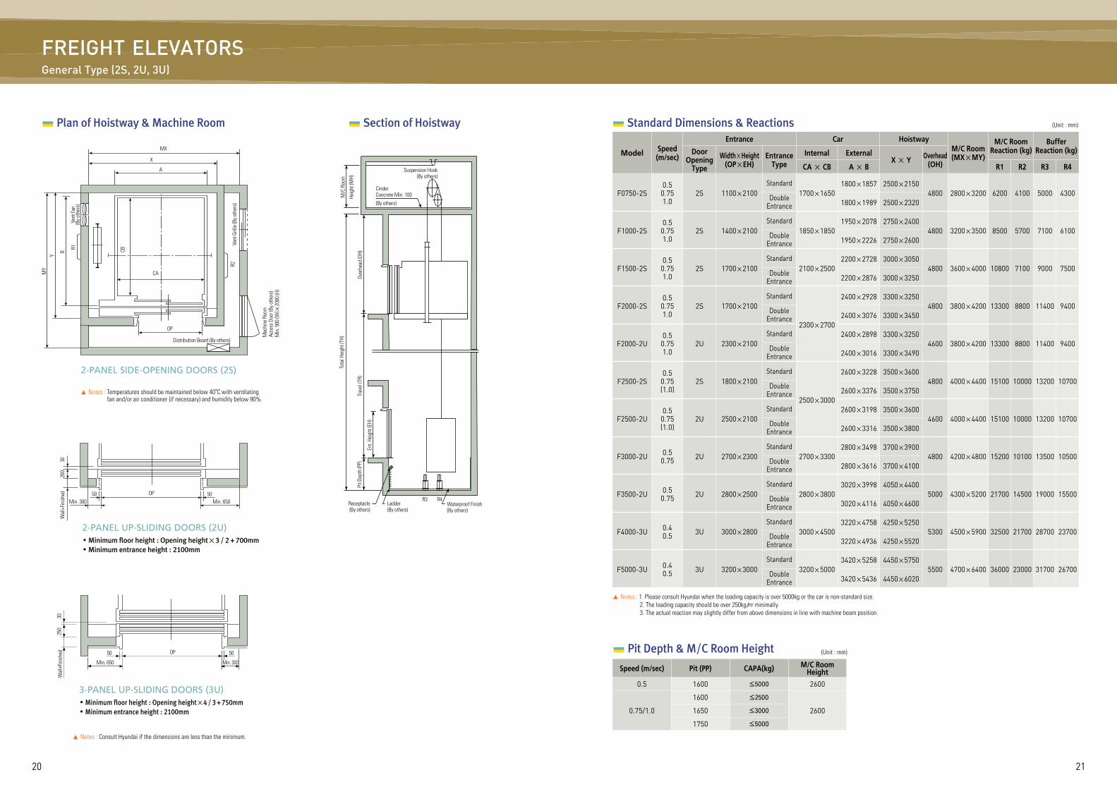
2-PANEL UP-SLIDING DOORS (2U)◦Minimum floor height : Opening height×3 / 2 + 700mm ◦Minimum entrance height : 2100mm
2-PANEL SIDE-OPENING DOORS (2S)
3-PANEL UP-SLIDING DOORS (3U)◦Minimum floor height : Opening height×4 / 3 + 750mm ◦Minimum entrance height : 2100mm
▲ Notes : Consult Hyundai if the dimensions are less than the minimum.
Wal
l+Fin
ished
Wal
l+Fin
ished
▲ Notes : Temperatures should be maintained below 40°C with ventilating fan and/or air conditioner (if necessary) and humidity below 90%.
Plan of Hoistway & Machine Room
Tota
l Hei
ght (
TH)
Over
head
(OH)
Trav
el (T
R)Pi
t Dep
th (P
P)
Ent.
Heig
ht (E
H)
M/C
Roo
mHe
ight
(MH)
Suspension Hook (By others)
Receptacle(By others)
Ladder(By others)
R3 R4Waterproof Finish(By others)
CinderConcrete Min. 100(By others)
Section of Hoistway
FREIGHT ELEVATORSGeneral Type (2S, 2U, 3U)
▲ Notes : 1. Please consult Hyundai when the loading capacity is over 5000kg or the car is non-standard size. 2. The loading capacity should be over 250kg/m2 minimally. 3. The actual reaction may slightly differ from above dimensions in line with machine beam position.
Model Speed(m/sec)
Entrance Car HoistwayM/C Room(MX×MY)
M/C RoomReaction (kg)
Buffer Reaction (kg)Door
OpeningType
Width×Height(OP×EH)
EntranceType
Internal ExternalX × Y Overhead
(OH)CA × CB A × B R1 R2 R3 R4
F0750-2S0.5
0.751.0
2S 1100×2100Standard
1700×16501800×1857 2500×2150
4800 2800×3200 6200 4100 5000 4300DoubleEntrance 1800×1989 2500×2320
F1000-2S0.5
0.751.0
2S 1400×2100Standard
1850×18501950×2078 2750×2400
4800 3200×3500 8500 5700 7100 6100DoubleEntrance 1950×2226 2750×2600
F1500-2S0.5
0.751.0
2S 1700×2100Standard
2100×25002200×2728 3000×3050
4800 3600×4000 10800 7100 9000 7500DoubleEntrance 2200×2876 3000×3250
F2000-2S0.5
0.751.0
2S 1700×2100Standard
2300×2700
2400×2928 3300×32504800 3800×4200 13300 8800 11400 9400Double
Entrance 2400×3076 3300×3450
F2000-2U0.5
0.751.0
2U 2300×2100Standard 2400×2898 3300×3250
4600 3800×4200 13300 8800 11400 9400DoubleEntrance 2400×3016 3300×3490
F2500-2S0.5
0.75(1.0)
2S 1800×2100Standard
2500×3000
2600×3228 3500×36004800 4000×4400 15100 10000 13200 10700Double
Entrance 2600×3376 3500×3750
F2500-2U0.5
0.75(1.0)
2U 2500×2100Standard 2600×3198 3500×3600
4600 4000×4400 15100 10000 13200 10700DoubleEntrance 2600×3316 3500×3800
F3000-2U 0.50.75 2U 2700×2300
Standard2700×3300
2800×3498 3700×39004800 4200×4800 15200 10100 13500 10500Double
Entrance 2800×3616 3700×4100
F3500-2U 0.50.75 2U 2800×2500
Standard2800×3800
3020×3998 4050×44005000 4300×5200 21700 14500 19000 15500Double
Entrance 3020×4116 4050×4600
F4000-3U 0.40.5 3U 3000×2800
Standard3000×4500
3220×4758 4250×52505300 4500×5900 32500 21700 28700 23700Double
Entrance 3220×4936 4250×5520
F5000-3U 0.40.5 3U 3200×3000
Standard3200×5000
3420×5258 4450×57505500 4700×6400 36000 23000 31700 26700Double
Entrance 3420×5436 4450×6020
Speed (m/sec) Pit (PP) CAPA(kg) M/C Room Height
0.5 1600 ≤5000 2600
0.75/1.0
1600 ≤2500
26001650 ≤3000
1750 ≤5000
(Unit : mm) Pit Depth & M/C Room Height
2322
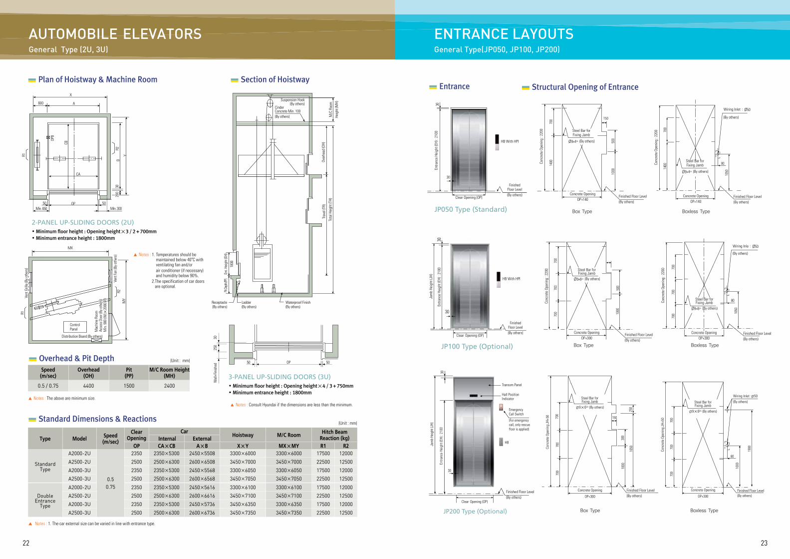
ENTRANCE LAYOUTSGeneral Type(JP050, JP100, JP200)
Receptacle(By others)
Ladder(By others)
Waterproof Finish(By others)
X
600 A
R1
OPB
CB
CA
OP
BR2
200
200
200
200
200
200
200
200
200
200
200
200
200200
30
Y
Suspension Hook(By others)
M/C
Roo
mHe
ight
(MH)
Over
head
(OH)
Trav
el (T
R)
Ent.
Heig
ht (E
H)18
00
Pit De
pth (PP
)
Tota
l Hei
ght (
TH)
CinderConcrete Min. 100(By others)
▲ Notes : 1. Temperatures should be maintained below 40°C with ventilating fan and/or
air conditioner (if necessary) and humidity below 90%. 2. The specification of car doors
are optional.
MX
Vent
Gril
le (B
y oth
ers)
MY
R2
R1
ControlPanel
Distribution Board (By others)
Mac
hine
Roo
mAc
cess
Doo
r (By
oth
ers)
Min
. 900
(W)×
2000
(H)
Vent
Fan
(By o
ther
s)
2-PANEL UP-SLIDING DOORS (2U)◦Minimum floor height : Opening height×3 / 2 + 700mm ◦Minimum entrance height : 1800mm
50Min. 650 Min. 300
50
Plan of Hoistway & Machine Room Section of Hoistway
AUTOMOBILE ELEVATORS General Type (2U, 3U)
OP50 50
250
30W
all+
Finish
ed
3-PANEL UP-SLIDING DOORS (3U)◦Minimum floor height : Opening height×4 / 3 + 750mm ◦Minimum entrance height : 1800mm
▲ Notes : Consult Hyundai if the dimensions are less than the minimum.
▲ Notes : 1. The car external size can be varied in line with entrance type.
Standard Dimensions & Reactions (Unit : mm)
Type Model Speed(m/sec)
Clear Opening
CarHoistway M/C Room Hitch Beam
Reaction (kg) Internal ExternalOP CA×CB A×B X×Y MX×MY R1 R2
StandardType
A2000-2U
0.50.75
2350 2350×5300 2450×5508 3300×6000 3300×6000 17500 12000
A2500-2U 2500 2500×6300 2600×6508 3450×7000 3450×7000 22500 12500
A2000-3U 2350 2350×5300 2450×5568 3300×6050 3300×6050 17500 12000
A2500-3U 2500 2500×6300 2600×6568 3450×7050 3450×7050 22500 12500
Double Entrance
Type
A2000-2U 2350 2350×5300 2450×5616 3300×6100 3300×6100 17500 12000
A2500-2U 2500 2500×6300 2600×6616 3450×7100 3450×7100 22500 12500
A2000-3U 2350 2350×5300 2450×5736 3450×6350 3300×6350 17500 12000
A2500-3U 2500 2500×6300 2600×6736 3450×7350 3450×7350 22500 12500
(Unit : mm)
▲ Notes : The above are minimum size.
Speed(m/sec)
Overhead(OH)
Pit(PP)
M/C Room Height(MH)
0.5 / 0.75 4400 1500 2400
Overhead & Pit Depth
Entrance Structural Opening of Entrance
ClearOpening (OP)
30
30
Entra
nce
Heig
ht (E
H) :
2100
Finished Floor Level(By others)
Clear Opening (OP)
HB With HPI
Concrete OpeningOP+140
Finished Floor Level(By others)
150
Steel Bar forFixing Jamb
Ø9×4EA (By others)
Conc
rete
Ope
ning
: 22
00
700
500
1000
1400
JP050 Type (Standard) Box Type
Steel Bar forFixing Jamb
Ø9×4EA (By others)
Wiring Inlet : Ø50
(By others)
Finished Floor Level(By others)
1050
80
Concrete OpeningOP+140
1400
700
Conc
rete
Ope
ning
: 22
00
Boxless Type
Finished Floor Level(By others)
30
30
Entra
nce
Heig
ht (E
H) :
2100
Jam
b He
ight
(JH)
Finished Floor Level(By others)
HB With HPI
Concrete OpeningOP+300
Steel Bar forFixing Jamb
Ø9×6EA (By others)
Conc
rete
Ope
ning
: 22
00
700
500
1000
700
700
JP100 Type (Optional) Box Type
Clear Opening (OP)
Wiring Inle : Ø50
(By others)
Finished Floor Level(By others)
80
Concrete OpeningOP+300
Steel Bar forFixing Jamb
Ø9×6EA (By others)
Conc
rete
Ope
ning
: 22
00 700
1050
700
700
Boxless Type
Box Type
Finished Floor Level(By others)
Concrete Opening
OP+300
150
Steel Bar forFixing Jamb
Ø9×6EA (By others)
Conc
rete
Ope
ning
:JH+
50 700
700
700
300
1000
1650
250
Boxless Type
Concrete Opening
OP+300
Steel Bar forFixing Jamb
Ø9×6EA (By others)
Conc
rete
Ope
ning
:JH+
50 700
700
700
1000
1900
Wiring Inlet :Ø50(By others)
Finished Floor Level(By others)
80
Finished Floor Level(By others)
HB
Hall PositionIndicator
Transom Panel
Entra
nce
Heig
ht (E
H) :
2100
Jam
b He
ight
(JH)
30
30
Emergency Call Switch
(For emergency call, only rescue floor is applied)
JP200 Type (Optional)
Clear Opening (OP)
2524
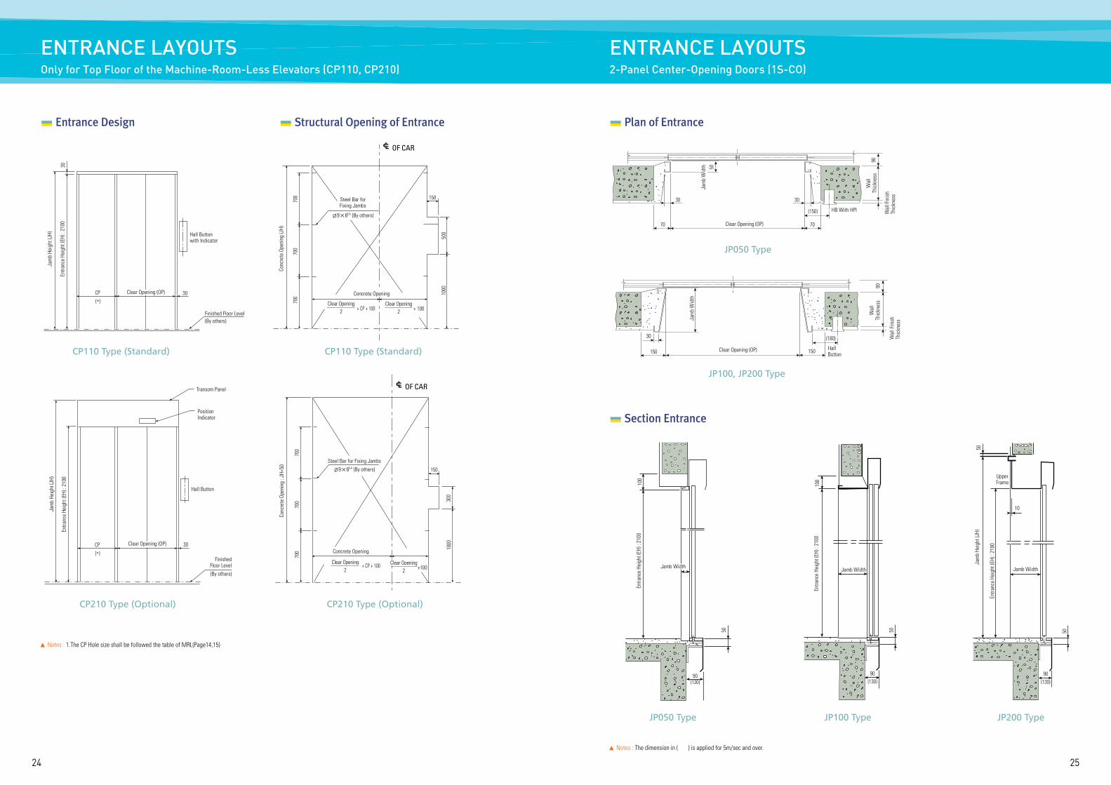
ENTRANCE LAYOUTS2-Panel Center-Opening Doors (1S-CO)
ENTRANCE LAYOUTSOnly for Top Floor of the Machine-Room-Less Elevators (CP110, CP210)
Entrance Design Structural Opening of Entrance
CP110 Type (Standard) CP110 Type (Standard)
Hall Buttonwith Indicator
Concrete Opening
150
Finished Floor Level(By others)
Steel Bar forFixing Jambs
Ø9×6EA (By others)
CP(*)
30Clear Opening (OP)
Jam
b He
ight
(JH)
30En
tranc
e He
ight
(EH)
: 21
00
Conc
rete
Ope
ning
(JH)
700
700
700
500
1000
OF CARLc
+ CP + 100Clear Opening
2 + 100Clear Opening
2
CP210 Type (Optional) CP210 Type (Optional)
Concrete OpeningFinished
Floor Level(By others)
Transom Panel
PositionIndicator
Hall Button
150
30 CP(*)
Steel Bar for Fixing JambsØ9×6EA (By others)
Conc
rete
Ope
ning
: JH
+50
Jam
b He
ight
(JH)
Entra
nce
Heig
ht (E
H) :
2100
700
700
700
300
1000
OF CARLc
Clear Opening (OP)
+ CP + 100Clear Opening
2Clear Opening
2Clear Opening
2Clear Opening
2Clear Opening
2Clear Opening
2Clear Opening
2Clear Opening
2Clear Opening
2Clear Opening
2Clear Opening
2Clear Opening
2Clear Opening
2Clear Opening
2Clear Opening
2Clear Opening
2Clear Opening
2Clear Opening
2Clear Opening
2Clear Opening
2Clear Opening
2Clear Opening
2Clear Opening
2 +100
▲ Notes : 1.The CP Hole size shall be followed the table of MRL(Page14,15)
Plan of Entrance
Jam
b W
idth
Jam
b W
idth
70
30 30
30
150 Clear Opening (OP) HallButton
(150)
70
150
(180)
HB With HPI
Wal
lTh
ickn
ess
Wal
lTh
ickn
ess
Wal
l Fin
ish
Thic
knes
sW
all F
inis
hTh
ickn
ess
9090
Clear Opening (OP)
Section Entrance
Jamb WidthJamb WidthJamb WidthJamb WidthJamb WidthJamb WidthJamb WidthJamb WidthJamb WidthJamb WidthJamb WidthJamb WidthJamb WidthJamb WidthJamb WidthJamb WidthJamb WidthJamb Width
90(130)
100
50
Entra
nce
Heig
ht (E
H) :
2100
JP050 Type
JP100, JP200 Type
UpperFrame
10
Jam
b He
ight
(JH)
Entra
nce
Heig
ht (E
H) :
2100
50
50
Jamb Width
90(130)
JP200 Type
100
50
90(130)
Entra
nce
Heig
ht (E
H) :
2100
Jamb Width
JP100 Type50
JP050 Type
▲ Notes : The dimension in ( ) is applied for 5m/sec and over.
2726
JP100 Type
Jamb Width
130
Entra
nce
Heig
ht (E
H) :
2100
100
50
JP200 Type
UpperFrame
10
Jam
b He
ight
(JH)
Entra
nce
Heig
ht (E
H) :
2100
50
50
Jamb Width
130
JP100, JP200 Type
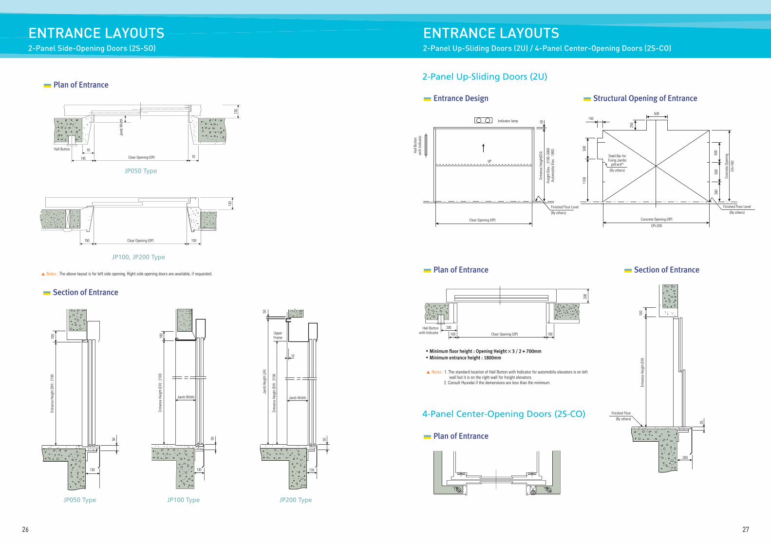
▲ Notes : The above layout is for left side opening. Right side opening doors are available, if requested.
Clear Opening (OP)
130
JP050 Type
70
70
Hall Button
Clear Opening (OP)
Jam
b W
idth
130
145
150 150
Plan of Entrance
JP050 Type
130
Entra
nce
Heig
ht (E
H) :
2100
50
100
Section of Entrance
ENTRANCE LAYOUTS2-Panel Up-Sliding Doors (2U) / 4-Panel Center-Opening Doors (2S-CO)
ENTRANCE LAYOUTS2-Panel Side-Opening Doors (2S-SO)
Entrance Design
Clear Opening (OP)
Finished Floor Level(By others)
Finished Floor Level(By others)
Hall
Butto
nw
ith In
dica
tor
UP
Indicator lamp
Entra
nce
Heig
ht(E
H)
Frei
ght E
lev.
: 210
0~30
00Au
tom
obile
Ele
v. : 1
800
50
Clear Opening (OP)
Hall Buttonwith Indicator
▲ Notes : 1. The standard location of Hall Button with Indicator for automobile elevators is on left wall but it is on the right wall for freight elevators. 2. Consult Hyundai if the demensions are less than the minimum.
Structural Opening of Entrance
Concrete Opening (OP)
OP+200
Steel Bar forFixing JambsØ9×6EA
(By others)
150500
250
500
500
50050
011
00
200
100 100
200
4-Panel Center-Opening Doors (2S-CO)
2-Panel Up-Sliding Doors (2U)
Plan of Entrance
Plan of Entrance
Entra
nce
Heig
ht (E
H)
Finished Floor(By others)
200
100
35
Section of Entrance
◦Minimum floor height : Opening Height×3 / 2 + 700mm ◦Minimum entrance height : 1800mm
Conc
rete
Ope
ning
EH+1
00
2928
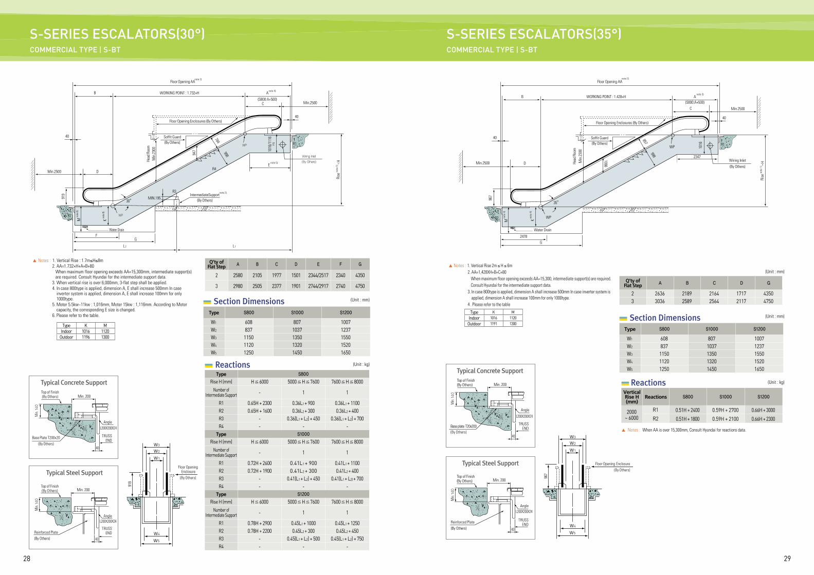
S-SERIES ESCALATORS(35°)COMMERCIAL TYPE | S-BT
S-SERIES ESCALATORS(30°) COMMERCIAL TYPE | S-BT
▲ Notes : 1. Vertical Rise : 1.7m≤H≤8m 2. AA=1.732×H+A+B+80 When maximum floor opening exceeds AA=15,300mm, intermediate support(s)
are required. Consult Hyundai for the intermediate support data. 3. When vertical rise is over 6,000mm, 3-flat step shall be applied. 4. In case 800type is applied, dimension A, E shall increase 500mm In case
inverter system is applied, dimension A, E shall increase 100mm for only 1000type.
5. Moter 5.5kw~11kw : 1,016mm, Moter 15kw : 1,116mm. According to Moter capacity, the corresponding E size is changed.
6. Please refer to the table.
Q’ty ofFlat Step A B C D E F G
2 2580 2105 1977 1501 2344/2517 2340 4350
3 2980 2505 2377 1901 2744/2917 2740 4750
Floor Opening AA
Head
Roo
mM
in.2
300
947
MIN.195
M no
te 6
)
K no
te 6
)
1016
/111
6주
5)
WORKING POINT : 1.732×H
WP
784
998
F
D
B
G
L2
919
R2
R1
R4
R3
40
30°
Floor Opening Enclosures (By Others)
Wiring Inlet
(By Others)
Rise
note
1) = H
WP
C
A
(S800:A+500)
40
Min.2500
Min.2500
Soffit Guard(By Others)
Water Drain
L1
IntermediateSupport (By Others)
note 2)
note 2)
note 4)
Reactions (Unit : kg)
Type S800
Rise H (mm) H 6000 5000 H 7600 7600 H 8000Number of
Intermediate Support - 1 1
R1 0.65H + 2300 0.36L1 + 900 0.36L1 + 1100R2 0.65H + 1600 0.36L2 + 300 0.36L2 + 400R3 - 0.36(L1 + L2) + 450 0.36(L1 + L2) + 700R4 - - -
Type S1000
Rise H (mm) H 6000 5000 H 7600 7600 H 8000Number of
Intermediate Support - 1 1
R1 0.72H + 2600 0.41L1 + 900 0.41L1 + 1100R2 0.72H + 1900 0.41L2 + 300 0.41L2 + 400R3 - 0.41(L1 + L2) + 450 0.41(L1 + L2) + 700R4 - - -
Type S1200
Rise H (mm) H 6000 5000 H 7600 7600 H 8000Number of
Intermediate Support - 1 1
R1 0.78H + 2900 0.45L1 + 1000 0.45L1 + 1250R2 0.78H + 2200 0.45L2 + 300 0.45L2 + 450R3 - 0.45(L1 + L2) + 500 0.45(L1 + L2) + 750R4 - - -
Enote 5)
Section DimensionsType S800 S1000 S1200
W1 608 807 1007W2 837 1037 1237W3 1150 1350 1550W4 1120 1320 1520W5 1250 1450 1650
(Unit : mm)
w3
w2
w1
w4
w5
919
Floor Opening Enclosure(By Others)
Typical Concrete Support
L200X200X24
Top of Finish(By Others)
Base Plate T200x20(By Others)
Min. 200
TRUSS END
TRUSS END
Angle
40
Min.
140
Reinforced Plate(By Others)
Min. 200
L200X200X24
Top of Finish(By Others)
Angle
40
Min.
140
Type K MIndoor 1016 1120
Outdoor 1196 1300
Typical Steel Support
M no
te 4
)
K no
te 4
)
1016
WORKING POINT : 1.428×H A(S800:A+500)
C
WP
B
857
998
G
967
R2
R1
40
40
D
35°
Wiring Inlet(By Others)
Rise
note
1) = H
WP
Floor Opening Enclosures (By Others)
Min.2500
Min.2500
Floor Opening AAnote 2)
note 3)
Soffit Guard(By Others)
Head
Roo
mM
in.2
300
Water Drain
1066
Reactions (Unit : kg)
▲ Notes : When AA is over 15,300mm, Consult Hyundai for reactions data.
Vertical Rise H (mm)
Reactions S800 S1000 S1200
2000 ~ 6000
R1 0.51H + 2400 0.59H + 2700 0.66H + 3000
R2 0.51H + 1800 0.59H + 2100 0.66H + 2300
▲ Notes : 1. Vertical Rise 2m ≤ H ≤ 6m 2. AA=1,428XH+B+C+80 When maximum floor opening exceeds AA=15,300, intermediate support(s) are required. Consult Hyundai for the intermediate support data. 3. In case 800type is applied, dimension A shall increase 500mm In case inverter system is
applied, dimension A shall increase 100mm for only 1000type. 4 . Please refer to the table
Section DimensionsType S800 S1000 S1200
W1 608 807 1007W2 837 1037 1237W3 1150 1350 1550W4 1120 1320 1520W5 1250 1450 1650
Q’ty ofFlat Step A B C D G
2 2636 2189 2164 1717 43503 3036 2589 2564 2117 4750
(Unit : mm)
(Unit : mm)
w3
w2
w1
w4
w5
967
Floor Opening Enclosure(By Others)
Typical Concrete Support
Typical Steel Support
Reinforced Plate(By Others)
Min. 200
L200X200X24
L200X200X24
Top of Finish (By Others)
Top of Finish (By Others)
Base plate T20x200(By Others)
Min. 200
TRUSSEND
TRUSSEND
40
40
Min.
140
Min.
140
2478
2347
Angle
Angle
Type K MIndoor 1016 1120
Outdoor 1191 1300
3130
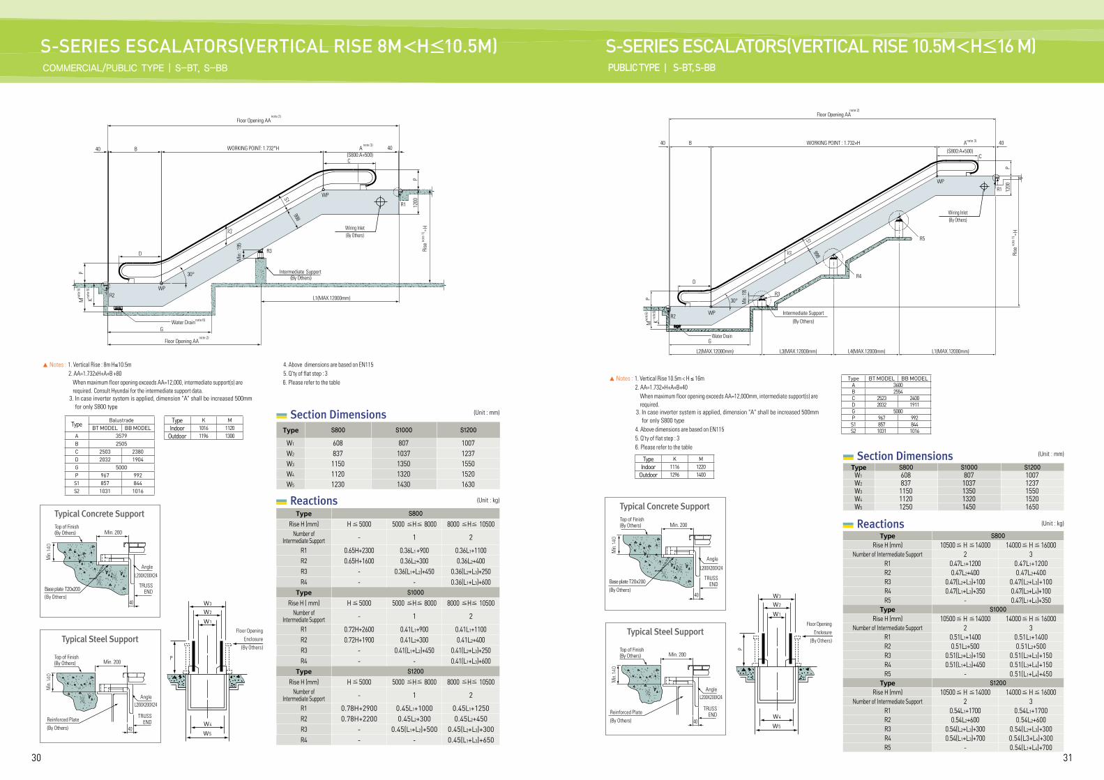
S-SERIES ESCALATORS(VERTICAL RISE 8M<H≤10.5M)COMMERCIAL/PUBLIC TYPE | S-BT, S-BB
S-SERIES ESCALATORS(VERTICAL RISE 10.5M<H≤16 M)PUBLIC TYPE | S-BT, S-BB
▲ Notes : 1. Vertical Rise : 8m H≤10.5m 2. AA=1.732xH+A+B +80 When maximum floor opening exceeds AA=12,000, intermediate support(s) are
required. Consult Hyundai for the intermediate support data. 3. In case inverter system is applied, dimension "A" shall be increased 500mm
for only S800 type
4. Above dimensions are based on EN115 5. Q'ty of flat step : 3 6. Please refer to the table
Reactions (Unit : kg)
Type S800
Rise H (mm) H 5000 5000 H 8000 8000 H 10500Number of
Intermediate Support - 1 2
R1 0.65H+2300 0.36L1 +900 0.36L1+1100R2 0.65H+1600 0.36L2+300 0.36L2+400R3 - 0.36(L1+L2)+450 0.36(L2+L3)+250R4 - - 0.36(L1+L3)+600
Type S1000
Rise H ( mm) H 5000 5000 H 8000 8000 H 10500Number of
Intermediate Support - 1 2
R1 0.72H+2600 0.41L1+900 0.41L1+1100R2 0.72H+1900 0.41L2+300 0.41L2+400R3 - 0.41(L1+L2)+450 0.41(L2+L3)+250R4 - - 0.41(L1+L3)+600
Type S1200
Rise H (mm) H 5000 5000 H 8000 8000 H 10500Number of
Intermediate Support - 1 2
R1 0.78H+2900 0.45L1+1000 0.45L1+1250R2 0.78H+2200 0.45L2+300 0.45L2+450R3 - 0.45(L1+L2)+500 0.45(L2+L3)+300R4 - - 0.45(L1+L3)+650
Section DimensionsType S800 S1000 S1200
W1 608 807 1007W2 837 1037 1237W3 1150 1350 1550W4 1120 1320 1520W5 1230 1430 1630
(Unit : mm)
TypeBalustrade
BT MODEL BB MODELA 3579B 2505C 2503 2380D 2032 1904G 5000P 967 992S1 857 844S2 1031 1016
Anote 3)
40WORKING POINT: 1.732*HB
C
WP
R2WP
R3
R1
30°
D
G
40
PM
Min
: 19
5
S2
S1998
K
P12
00
L1(MAX.12000mm)
(S800:A+500)
Intermediate Support (By Others)
Wiring Inlet(By Others)
Floor Opening AAnote 2)
Water Drain note 6)
Rise
note
1) = H
w3
w2
w1
w4
w5
P
Floor Opening Enclosure
(By Others)
Typical Concrete Support
Typical Steel Support
Reinforced Plate(By Others)
Min. 200
L200X200X24
L200X200X24
Top of Finish (By Others)
Top of Finish (By Others)
Base plate T20x200(By Others)
Min. 200
TRUSSEND
Angle
TRUSSEND
40
40
Min.
140
Min.
140
Angle
Floor Opening AAnote 2)
Type K MIndoor 1016 1120
Outdoor 1196 1300
note
6)
note
6)
▲ Notes : 1. Vertical Rise 10.5m < H ≤ 16m 2. AA=1.732×H+A+B+40 When maximum floor opening exceeds AA=12,000mm, intermediate support(s) are
required. 3. In case inverter system is applied, dimension "A" shall be increased 500mm
for only S800 type 4. Above dimensions are based on EN115 5. Q'ty of flat step : 3 6. Please refer to the table
Reactions (Unit : kg)
Type S800
Rise H (mm) 10500 H 14000 14000 H 16000Number of Intermediate Support 2 3
R1 0.47L1+1200 0.47L1+1200R2 0.47L2+400 0.47L2+400R3 0.47(L2+L3)+100 0.47(L2+L3)+100R4 0.47(L1+L3)+350 0.47(L3+L4)+100R5 - 0.47(L1+L4)+350
Type S1000
Rise H (mm) 10500 H 14000 14000 H 16000Number of Intermediate Support 2 3
R1 0.51L1+1400 0.51L1+1400R2 0.51L2+500 0.51L2+500R3 0.51(L2+L3)+150 0.51(L2+L3)+150R4 0.51(L1+L3)+450 0.51(L3+L4)+150R5 - 0.51(L1+L4)+450
Type S1200
Rise H (mm) 10500 H 14000 14000 H 16000Number of Intermediate Support 2 3
R1 0.54L1+1700 0.54L1+1700R2 0.54L2+600 0.54L2+600R3 0.54(L2+L3)+300 0.54(L2+L3)+300R4 0.54(L1+L3)+700 0.54(L3+L4)+300R5 - 0.54(L1+L4)+700
Section DimensionsType S800 S1000 S1200
W1 608 807 1007W2 837 1037 1237W3 1150 1350 1550W4 1120 1320 1520W5 1250 1450 1650
(Unit : mm)Type K M
Indoor 1116 1220Outdoor 1296 1400
w3
w2
w1
w4
w5
P
Floor Opening Enclosure
(By Others)
Typical Concrete Support
Typical Steel Support
Reinforced Plate(By Others)
Min. 200
L200X200X24
L200X200X24
Top of Finish (By Others)
Top of Finish (By Others)
Base plate T20x200(By Others)
Min. 200
TRUSS END
Angle
TRUSS END
Angle
40
40
Min.
140
Min.
140
Type BT MODEL BB MODELA 3600B 2554C 2523 2400D 2032 1911G 5000P 967 992S1 857 844S2 1031 1016
M Knote
5)
note
5)
Min
: 195
P
P12
00
A
C
40
D
WP
WP
30°
R2
S1
S2 998
R3
R1
R4
R5
Wiring Inlet(By Others)
GWater Drain
L2(MAX.12000mm) L3(MAX.12000mm) L4(MAX.12000mm) L1(MAX.12000mm)
B WORKING POINT : 1.732×H(S800:A+500)
Rise
note
1) = H
40
Intermediate Support(By Others)
note 3)
note 2)Floor Opening AA
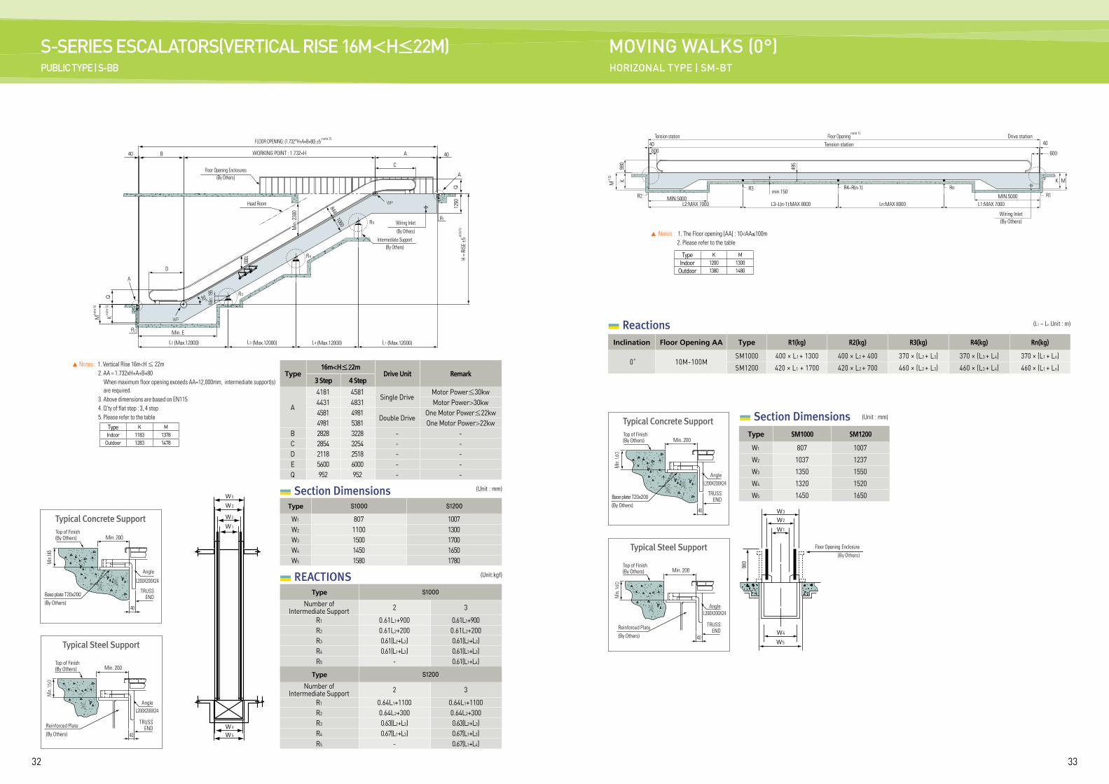
3332
S-SERIES ESCALATORS(VERTICAL RISE 16M<H≤22M) PUBLIC TYPE | S-BB
MOVING WALKS (0°)HORIZONAL TYPE | SM-BT
Section Dimensions
REACTIONS
Type16m<H≤22m
Drive Unit Remark3 Step 4 Step
A
4181 4581Single Drive
Motor Power≤30kw4431 4831 Motor Power>30kw4581 4981
Double DriveOne Motor Power≤22kw
4981 5381 One Motor Power>22kwB 2828 3228 - -C 2854 3254 - -D 2118 2518 - -E 5600 6000 - -Q 952 952 - -
Type S1000 S1200
W1 807 1007W2 1100 1300W3 1500 1700W4 1450 1650W5 1580 1780
Type S1000
Number ofIntermediate Support 2 3
R1 0.61L1+900 0.61L1+900R2 0.61L2+200 0.61L2+200R3 0.61(L2+L3) 0.61(L2+L3)R4 0.61(L1+L3) 0.61(L1+L3)R5 - 0.61(L1+L4)
Type S1200
Number ofIntermediate Support 2 3
R1 0.64L1+1100 0.64L1+1100R2 0.64L2+300 0.64L2+300R3 0.63(L2+L3) 0.63(L2+L3)R4 0.67(L1+L3) 0.67(L1+L3)R5 - 0.67(L1+L4)
(Unit : mm)
(Unit:kgf)
▲ Notes : 1. Vertical Rise 16m<H ≤ 22m 2. AA = 1.732xH+A+B+80 When maximum floor opening exceeds AA=12,000mm, intermediate support(s)
are required. 3. Above dimensions are based on EN115 4. Q'ty of flat step : 3, 4 step 5. Please refer to the table
B A
C
844
1000
Q
A
R1
40 40
A
D
30 °
Min
. 230
0
R2
L2 (Max.12000) L3 (Max.12000) L4 (Max.12000) L1 (Max.12000)
Head Room
Floor Opening Enclosures(By Others)
Wiring Inlet(By Others)
1290
H =
RISE
±5
Q
FLOOR OPENING: (1.732*H+A+B+80) ±5
WORKING POINT : 1.732×H
1060
WP
WP
Min. E
Intermediate Support(By Others)
note 2)
note
1)
R3
R4
R5
w 5
w 5
w 4
w 3
w 2
w 1
Mno
te 5
)
Kno
te 5
) Min
: 195
▲ Notes : 1. The Floor opening [AA] : 10<AA≤100m 2. Please refer to the table
Reactions (L1 ~ Ln Unit : m)
Inclination Floor Opening AA Type R1(kg) R2(kg) R3(kg) R4(kg) Rn(kg)
0° 10M-100MSM1000 400 × L1 + 1300 400 × L2 + 400 370 × (L2 + L3) 370 × (L3 + L4) 370 × (L1 + Ln)
SM1200 420 × L1 + 1700 420 × L2 + 700 460 × (L2 + L3) 460 × (L3 + L4) 460 × (L1 + Ln)
Section Dimensions (Unit : mm)
Type SM1000 SM1200
W1 807 1007
W2 1037 1237
W3 1350 1550
W4 1320 1520
W5 1450 1650
w3
w2
w1
w4
w5
980
Floor Opening Enclosure(By Others)
Typical Concrete Support
Typical Steel Support
Reinforced Plate(By Others)
Min. 200
L200X200X24
L200X200X24
Top of Finish (By Others)
Top of Finish (By Others)
Base plate T20x200(By Others)
Min. 200
TRUSS END
Angle
TRUSS END
40
40
Min.
140
Min.
140
Type K MIndoor 1200 1300
Outdoor 1380 1480
40
R2
M주
2)
M
40
600
K KR3 R4~R(n-1)
min.150Rn
R1
600
MIN.5000 MIN.5000
Floor OpeningTension station
Drive stationTension station
980
495
L2:MAX 7000 L3~L(n-1):MAX 8000 Ln:MAX 8000 L1:MAX 7000
Wiring Inlet(By Others)
note 1)
Angle
Type K MIndoor 1183 1378
Outdoor 1283 1478
Typical Concrete Support
Typical Steel Support
Reinforced Plate(By Others)
Min. 200
L200X200X24
L200X200X24
Top of Finish (By Others)
Top of Finish (By Others)
Base plate T20x200(By Others)
Min. 200
TRUSS END
Angle
TRUSS END
Angle
40
40
Min.
145
Min.
150
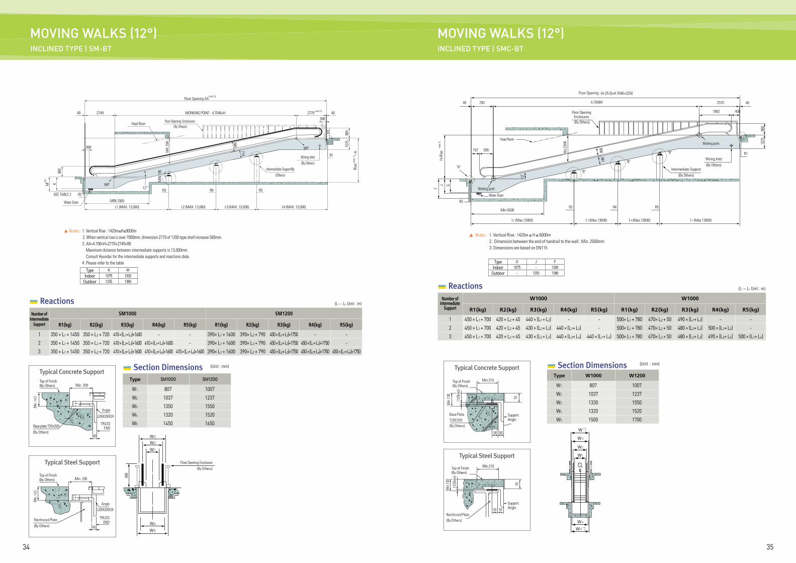
3534
MOVING WALKS (12°)INCLINED TYPE | SM-BT
MOVING WALKS (12°)INCLINED TYPE | SMC-BT
Section Dimensions (Unit : mm)
Type SM1000 SM1200
W1 807 1007
W2 1037 1237
W3 1350 1550
W4 1320 1520
W5 1450 1650
▲ Notes : 1. Vertical Rise : 1420m≤H≤9000m 2. When vertical rise is over 7000mm, dimension 2770 of 1200 type shall increase 500mm. 3. AA=4.706×H+2770+2749+80 Maximum distance between intermediate supports is 13,000mm. Consult Hyundai for the intermediate supports and reactions data. 4. Please refer to the table
Reactions (L1 ~ Ln Unit : m)
Number ofIntermediate
Support
SM1000 SM1200
R1 (kg) R2 (kg) R3 (kg) R4 (kg) R5 (kg) R1 (kg) R2 (kg) R3 (kg) R4 (kg) R5 (kg)
1 350 × L1 + 1450 350 × L2 + 720 410 × (L1 + L2)+1600 - - 390× L1 + 1600 390× L2 + 790 450 × (L1+ L2)+1750 - -
2 350 × L1 + 1450 350 × L2 + 720 410 × (L2+ L3)+1600 410 × (L1+ L3)+1600 - 390× L1 + 1600 390× L2 + 790 450 × (L2+ L3)+1750 450 × (L1+ L3)+1750 -
3 350 × L1 + 1450 350 × L2 + 720 410 × (L2+ L3)+1600 410 × (L3+ L4)+1600 410 × (L1+ L4)+1600 390× L1 + 1600 390× L2 + 790 450 × (L2+ L3)+1750 450 × (L3+ L4)+1750 450 × (L1+ L4)+1750
Type K MIndoor 1075 1200
Outdoor 1255 1380
w3
w2
w1
w4
w5
980
Floor Opening Enclosure(By Others)
Typical Concrete Support
Typical Steel Support
Reinforced Plate(By Others)
Min. 200
L200X200X24
L200X200X24
Top of Finish (By Others)
Top of Finish (By Others)
Base plate T20x200(By Others)
Min. 200
TRUSS END
TRUSS END
40
40
Min.
140
Min.
140
Floor Opening AA
M K주4)
MIN
. 230
0
980
714
980
980
1075
Rise
note
1) = H
40 2749 2770WORKING POINT : 4.7046×H 40398
970
398
WP
MIN.7000
L1 (MAX. 13,000) L2 (MAX. 13,000)
Intermediate SupportBy (Others)
Wiring Inlet(By Others)
L3 (MAX. 13,000) L4 (MAX. 13,000)
R2R312°
R1
R4 R5SEE TABLE 2
Water Drain
WP
Floor Opening Enclosures(By Others)
Head Room
note 3)
note 2)
Angle
Angle
MIN
.195
Section Dimensions (Unit : mm)
Type W1000 W1200
W1 807 1007
W2 1037 1237
W3 1330 1550
W4 1320 1520
W5 1500 1700
▲ Notes : 1. Vertical Rise : 1420m ≤ H ≤ 6000m 2. Dimension between the end of handrail to the wall : Min. 2500mm 3. Dimensions are based on EN115
Reactions (L1 ~ Ln Unit : m)
Number ofIntermediate
Support
W1000 W1000
R1 (kg) R2 (kg) R3 (kg) R4 (kg) R5 (kg) R1 (kg) R2 (kg) R3 (kg) R4 (kg) R5 (kg)
1 450 × L1 + 700 420 × L2 + 45 440 × (L1 + L2) - - 500× L1 + 780 470× L2 + 50 490 × (L1+ L2) - -
2 450 × L1 + 700 420 × L2 + 45 430 × (L2 + L3) 440 × (L1+ L3) - 500× L1 + 780 470× L2 + 50 480 × (L2+ L3) 500 × (L1+ L3) -
3 450 × L1 + 700 420 × L2 + 45 430 × (L2 + L3) 440 × (L3+ L4) 440 × (L1+ L4) 500× L1 + 780 470× L2 + 50 480 × (L2+ L3) 490 × (L3+ L4) 500 × (L1+ L4)
ww 3
w1
w2
w 4
w 5
Typical Concrete Support
50 50
70
Top of Finish (By Others)
Support Angle
Support Angle
Min.210
Base Plate T20X200(By Others)
11(S
him
)
Min
.130
Typical Steel Support
50 50
70
Min.210Top of Finish (By Others)
Reinforced Plate(By Others)
11(S
him
)
Min
.130
Floor Opening : (H-25.6)×4.7046+3250
Min
.230
0
861866
980
1075
40 793 4.7046H 2370
1962 408
595197
40
R2R3 R5
12°
Working point
Working point
Water Drain
Head Room
Wiring Inlet (By Others)
Floor Opening Enclosures (By Others)
R1
Intermediate Support(By Others)
Min.5500
L2 (Max.13000) L3 (Max.13000) L4 (Max.13000) L1 (Max.13000)
J
"A""B"
"B"
"B"
FH=
Rise
note
1)
G
R4
CL
+10 0
+10 0
Type G J FIndoor 1075 - 1200
Outdoor - 1255 1380
3736
Following construction and electric works are not included in our supply scope for elevators, escalators, and moving walks. These should be carried out by the building construction companies. (Note: For elevators without machine room, please contact us.)
Elevator
Escalator/Moving Walk
Hoistway1. Forming holes on the wall surrounding the exit on each floor (exit, hall button, hall
lantern, etc.), and finishing the walls and floors after installing the elevator (including mortar filling)
2. Installation of steel frame to fix the left/right jambs on the exit3. Installation of ladder for pit inspection4. Waterproofing work inside the pit and finishing work after attaching the buffer5. Installation of hoistway partitions or separating beams (when necessary)6. Removing various tie pins and molds7. Others (items indicated on the floor plan)8. Construction of concrete structures (thickness of 150mm or above) or beam
structures that can fasten the rail brackets in the hoistway wall9. Supplying storage for construction tools and materials free of charge10. Destruction and finishing of concrete structures that are not constructed as
indicated on the blueprint11. Installation of lighting within hoistway (install lighting of 100 Lux or above on upper
and lower part of the hoistway)12. Installation of tensile beam or hook that is designed to lift the machine to the
ceiling of hoistway
Machine Room1. Forming holes for machines and ropes on the floor, finishing on cinder
concrete, and installation of those indicated on the floor plan2. Installation of pulley beam or hook on the ceiling of machine room3. Installation of reinforcement beam on machine room floor (when necessary)4. Supplying water used for construction free of charge
5. Supplying storage for construction tools and materials free of charge
Construction Work
Hoistway1. Installation of natural or artificial lighting of 50 Lux or above (measured from
the floor) on platform of each floor (150 Lux in case of an elevator for the handicapped)
2. Piping and wiring work from monitoring panel to hoistway when monitoring panel is installed
3. Piping and wiring work when CCTV is installed4. Others (items indicated on the floor plan)5. Wiring work on power system within the hoistway for supplying power and
lighting (refer to the floor plan for building power facilities regarding the capacity of power facilities.)
6. Installation of distribution box for elevator (including N.F.B) on electrical room (install near the hoistway. refer to the floor plan for building power facilities regarding the capacity of power facilities.)
7. Construction for power facilities to maintain the voltage regulation of distribution source within +5 % to -10 % and lighting within ±2 %
8. Piping and wiring work on lighting outlet for pit inspection9. Supplying power needed during installation and commissioning free of charge10. Piping and wiring work on emergency communication device between
elevator control panel, central control(Wire specifications: UTP 0.5 mm x 2P per each elevator) 1) Communication device that connects the inside and outside of the elevator
should be installed redundantly on the area where the managing personnel is stationed (security office, electric room, and central control room). In case of the facility where the managing personnel is stationed in only one place, however, only one communication device may be installed.
2) Also, a communication device that automatically requests for help to maintenance company or self-inspector should be installed in order to deal with the situation where the internal communication is not established.
Machine Room1. Piping and wiring work outside the hoistway when interphone is installed on
places other than the machine room2. Construction of lighting and lighting outlets for inspection in machine room3. Supplying power needed during installation and commissioning free of charge4. Installation of lighting for power system and cage, and construction of
machine room incoming panel and its wiring for emergency power5. Installation of permanent lighting that can be separated from the power for
elevator and provide light of 200 Lux or above from the floor in machine room
Electric Work
CONSTRUCTIONS EXCLUDED FROM OUR SUPPLY SCOPE FOR ELEVATORS /ESCALATORS / MOVING WALKS ELECTRIC POWER REQUIREMENTS
(By Others)
1. Forming holes on the floor slab for installation and filling the holes after installation
2. Installation of intermediate strut beams for installation (when necessary)3. Forming holes on the floor slab for introducing escalator/moving walk and
filling the holes after installation4. Construction and waterproofing work on the lowest floor and lower pit of the
escalator/moving walk (Constructing fire-proof pit when there is a living room under the lower machine room)
5. Finishing work on floor and ceiling around the escalator/moving walk6. Construction of handle around escalator/moving walk 7. Bordering work on
the part where the ceiling of the building and the escalator/moving walk meet each other
8. Installation of fall protection net in case that the floor of escalator/moving walk has a hole
9. Forming holes for introducing the escalator/moving walk and filling the holes after installation
10. Curing and restoring the borders of escalator/moving walk when it is installed on an existing building
11. Supplying storage for construction tools and materials free of charge12. Exterior work on escalator/moving walk
Construction Work
1. Power system and lighting: Piping and wiring work on upper incoming panel of escalator/moving walk
2. Power for inspection: Piping and wiring work on upper incoming panel of escalator/moving walk
3. Grounding wire (class III): Piping and wiring work on upper incoming panel of escalator/moving walk
4. Piping and wiring work for the installation of fire-proof shutter and electrical contacts up to the upper control panel of escalator/moving walk (Piping and wiring work on electrical contacts and monitoring panels)
5. Supplying power needed during installation and commissioning free of charge
Electric Work
1. Exit for machine room should be made of fire-proof material and should be installed in a structure that does not lead to other places.
2. Do not install ducts or pipes for other purposes (electricity, water, gas, hydrant) on the hoistway and walls inside the machine room.
3. Lower part of pit should not be used as residence, pathway, or for other purposes.
4. Power and voltage regulation should be within +5 % to -10 %.5. Temperature in machine room should be 40℃ and humidity should be 90 % or
below. Be sure to install the entilation window, ventilator, or other air-conditioning facilities to prevent generation of dust or poisonous gas inside the machine room.
※ When you wish to build the hoistway in steel frame, please contact us. (Steel frame construction for hoistway is excluded from our supply scope.)
※ Construction errors: Inner hoistway size that is indicated on the blueprint of this catalog is the minimum size that is designed to fit the size of the elevator interior. So, the construction error limit for hoistway width and overall height is ±30 mm.
※Calculation equation for heat generation in machine room (based on one elevator)
Q: (kcal/H) = W×V×F×NW: Loading capacity (kg) N: Number of elevatorsV: Rated speed (m/min) F: Coefficient based on control type (1/42 : VVVF)
Matters to Note
(380V) Elevator(1.0~2.5 m/sec)
Load(kg)
Speed(m/sec)
MotorCapacity
(kW)
MCCB Capacityof Building (A)
Power SupplyCapacity (kVA)
Power Cable Size(mm²)
Earth Wire Size(mm²)
1Car 2Cars 1Car 2Cars 1Car 2Cars 1Car 2Cars
450
1.0 2.8 20 20 6 11 4 4 6 6
1.5 4.2 20 30 7 14 4 6 6 6
1.75 4.9 20 30 9 18 4 6 6 6
550
1.0 3.4 20 20 7 13 7 4 6 6
1.5 5.1 20 30 9 18 4 6 6 6
1.75 5.9 20 40 11 21 4 10 6 6
600
1.0 3.7 20 20 7 13 4 4 6 6
1.5 5.6 20 30 10 19 4 6 6 6
1.75 6.5 20 40 12 23 4 10 6 6
700
1.0 4.3 20 30 7 14 4 6 6 6
1.5 6.5 20 40 12 23 4 10 6 6
1.75 7.5 20 40 13 26 4 10 6 6
750
1.0 4.6 20 30 8 16 4 6 6 6
1.5 6.9 20 40 12 24 4 10 6 6
1.75 8.1 30 50 14 28 6 16 6 10
900
1.0 5.6 20 30 10 19 4 6 6 6
1.5 8.3 30 50 14 28 6 16 6 10
1.75 9.7 30 60 17 34 6 16 6 10
2.0 11.1 30 60 20 39 6 16 6 10
2.5 14.8 50 100 25 50 16 35 10 16
1000
1.0 6.2 20 40 11 21 4 10 6 6
1.5 9.2 30 50 16 31 6 16 6 10
1.75 10.8 30 60 19 37 6 16 6 10
2.0 12.3 40 75 21 42 10 25 6 16
2.5 16.4 50 100 28 55 16 35 10 16
1150
1.0 7.1 20 40 12 24 4 10 6 6
1.5 10.6 30 60 19 37 6 16 6 10
1.75 12.4 40 75 21 42 10 25 6 16
2.0 14.1 40 75 25 49 10 25 6 16
2.5 18.8 60 100 32 63 16 35 10 16
1350
1.0 8.3 30 50 14 28 6 16 6 10
1.5 12.4 40 75 22 44 10 25 6 16
1.75 14.5 40 100 26 51 10 35 6 16
2.0 16.6 50 100 29 57 16 35 10 16
2.5 22.1 75 125 37 74 25 50 16 25
1600
1.0 9.8 30 60 18 36 6 16 6 10
1.5 14.7 40 100 26 51 10 35 6 16
1.75 17.2 50 100 30 59 16 35 10 16
2.0 19.7 60 125 35 69 16 50 10 25
2.5 26.2 75 125 39 77 25 50 16 25
▲ Notes : 1. Above power feeder sizes are for the length of electric wire up to 50m from elevator machine room to power.For the length being 50m or more, the following formular should be applied.
2. Above cable sizes are for copper wires inside electrometallic tubings. Cable length(m) 50 3. For power requirement of 3 cars or more, consult Hyundai. 4. Machine room temperature should be maintained below 40℃ with ventilating fan and air conditioner, and below 90%.
×Size in the above(mm²) Cable sizes(mm²) =
3938
Elevator(3.0~10.0 m/sec)(380V)
ELECTRIC POWER REQUIREMENTS(By others)
Load(kg)
Speed(m/sec)
MotorCapacity
(kW)
MCCB Capacityof Building (A)
Power SupplyCapacity (kVA)
Power Cable Size(mm²)
Earth Wire Size(mm²)
1Car 2Cars 1Car 2Cars 1Car 2Cars 1Car 2Cars
900 3.0 16.6 50 100 30 59 16 35 10 16
1000
3.0 18.4 60 125 32 64 16 50 10 25
3.5 23.0 75 125 38 76 25 50 16 25
4.0 26.0 100 150 44 87 35 70 16 25
1150
3.0 21.2 75 125 38 76 25 50 16 25
3.5 25 75 150 44 87 25 70 16 25
4.0 30 100 175 50 99 35 95 16 25
5.0 36 125 200 63 125 50 95 25 50
6.0 43 125 250 74 148 50 120 25 95
7.0 50 125 250 77 154 50 120 25 95
8.0 57 150 300 88 175 70 150 25 95
9.0 64 175 350 98 186 95 150 25 120
10.0 71 175 350 109 218 95 150 25 120
1350
3.0 25 75 150 44 87 25 70 16 25
3.5 30 100 175 51 102 35 95 16 25
4.0 35 125 200 58 115 50 95 25 50
5.0 42 125 250 74 148 50 120 25 95
6.0 50 150 300 88 175 70 150 25 95
7.0 58 150 300 90 180 70 150 25 95
8.0 67 175 350 103 205 95 150 25 120
9.0 75 200 400 115 230 95 150 50 150
10.0 83 225 400 127 254 95 150 50 150
1600
3.0 30 100 175 52 104 35 95 16 25
3.5 35 125 200 60 120 50 95 25 50
4.0 40 125 225 69 138 50 95 25 50
5.0 50 150 300 87 173 70 150 25 95
6.0 60 175 350 103 206 95 150 25 120
7.0 69 175 350 107 214 95 150 25 120
8.0 79 200 400 122 243 95 150 50 150
9.0 89 225 500 136 272 95 240 50 185
10.0 98 250 500 151 302 120 240 95 185
ELECTRIC POWER REQUIREMENTS(By Others)
▲ Notes : 1. The above power sizes are for lengths of electric wire up to 50m from the elevator machine room to the transformer. For lengths of 50m or more, the following formula should be applied: Power feeder length(m) 50
2. Above power feeder sizes are for copper wires inside electro-metallic tubing. 3. It is recommended a larger diameter earth wire be used. 4. For installing several elevators. apply the following formula. Transformer Capacity(KVA)=Number of elevator X Diversity factor.
Number of elevator(N) 1 2 3 4 5Diversity Factor 1.00 0.91 0.85 0.80 0.76
×Size in the above(mm²)Power feeder size(mm²) =
[220V / 380V] MRL(Machine-Room less) Elevator | 1.0~1.75m/sec
Load(kg)
Speed(m/sec)
MotorCapacity
(kW)
MCCB Capacityof Building (A)
Power SupplyCapacity (kVA)
Power Cable Size(mm²)
Earth Wire Size(mm²)
Starting Power
(kVA/car)1Car 2Cars 1Car 2Cars 1Car 2Cars 1Car 2Cars
450
1.0 3.0 20/20 30/20 6 11 4/4 8/4 6/6 6/6 121.5 4.5 30/20 50/30 8 16 7/4 16/6 6/6 6/6 16
1.75 5.2 30/20 50/30 10 19 8/4 16/6 6/6 6/6 19
5501.0 3.6 20/20 40/20 7 13 5/4 10/4 6/6 6/6 141.5 5.4 30/20 50/30 10 19 8/4 16/6 6/6 6/6 19
1.75 6.3 30/20 60/40 12 23 10/4 18/10 6/6 10/6 23
6001.0 3.9 20/20 40/30 8 15 6/4 11/6 6/6 6/6 161.5 5.9 30/20 60/40 11 21 9/4 17/10 6/6 10/6 21
1.75 6.9 40/20 75/40 13 25 11/4 25/10 6/6 10/6 25
7001.0 4.6 30/20 50/30 9 17 7/4 16/6 6/6 6/6 181.5 6.9 40/20 75/40 13 25 11/4 25/10 6/6 10/6 25
1.75 8.1 40/30 100/50 15 29 13/6 35/16 6/6 16/6 29
7501.0 4.9 30/20 50/30 9 18 8/4 16/6 6/6 6/6 181.5 7.4 40/20 75/40 13 26 12/4 25/10 6/6 10/6 25
1.75 8.6 40/30 100/50 15 30 13/6 35/16 6/6 16/6 29
900
1.0 5.9 30/20 60/40 11 21 9/4 17/10 6/6 10/6 211.5 8.9 50/30 100/50 16 31 16/6 35/16 6/6 16/6 31
1.75 10.3 50/30 100/60 19 37 16/6 35/16 6/6 16/10 372.0 11.8 60/30 125/60 20 39 18/6 50/16 10/6 25/10 382.5 14.8 75/50 150/100 25 50 25/16 70/35 16/10 25/16 48
1000
1.0 6.6 40/20 75/40 12 23 10/4 25/10 6/6 10/6 231.5 9.8 50/30 100/60 18 36 16/6 35/16 6/6 16/10 35
1.75 11.5 60/40 125/75 21 41 18/10 50/25 10/6 25/10 402.0 13.1 60/40 125/75 22 43 19/10 50/25 10/6 25/16 422.5 16.4 75/50 150/100 28 55 25/16 70/35 16/10 25/16 54
1150
1.0 7.5 40/20 75/40 14 27 12/4 25/10 6/6 10/6 271.5 11.3 60/40 125/75 21 41 18/10 50/25 10/6 25/10 40
1.75 13.2 75/40 125/75 24 47 25/10 50/25 10/6 25/10 462.0 15.1 75/40 150/75 25 49 25/10 70/25 10/6 25/16 482.5 18.8 100/60 175/100 32 63 35/16 95/35 16/10 25/16 61
1350
1.0 8.9 50/30 100/50 16 31 16/6 35/16 6/6 16/6 311.5 13.3 75/40 125/75 24 47 25/10 50/25 10/6 25/10 46
1.75 15.5 75/50 125/100 27 54 25/16 50/35 10/6 25/16 522.0 17.7 75/50 150/100 29 57 27/16 70/35 16/10 25/16 562.5 22.1 100/75 200/125 37 74 35/25 95/50 25/16 35/25 71
1600
1.0 10.5 50/30 100/60 19 37 16/6 35/16 6/6 16/10 371.5 15.7 75/50 150/100 28 56 25/16 70/35 10/6 25/16 54
1.75 18.3 75/50 150/100 32 64 29/16 70/35 10/6 25/16 612.0 21.0 100/60 175/125 35 69 35/16 95/50 25/10 35/25 672.5 26.2 125/75 225/125 39 77 50/25 95/50 35/16 50/25 75
1800
1.0 11.8 60/30 125/60 20 39 18/6 50/16 16/6 35/10 381.5 17.7 75/50 150/100 29 57 27/16 70/35 16/10 25/16 56
1.75 20.6 100/60 175/125 34 67 35/16 95/50 25/16 35/25 652.0 23.6 100/60 200/125 39 77 35/16 95/50 35/16 50/25 752.5 29.5 125/75 250/150 43 86 50/25 120/70 35/16 70/25 82
2000
1.0 13.1 60/40 125/75 22 43 19/10 50/25 16/10 25/16 421.5 19.7 75/50 150/100 31 62 29/16 70/35 25/16 35/25 59
1.75 22.9 100/60 175/125 37 74 35/16 95/50 25/16 35/25 712.0 26.2 100/60 200/125 38 75 39/16 95/50 35/16 50/25 732.5 32.7 150/75 300/150 48 96 70/25 150/70 35/25 70/50 92
2500
1.0 16.4 75/40 125/100 26 52 25/10 50/35 25/10 35/25 501.5 24.6 100/60 200/125 40 79 36/16 95/50 35/10 50/25 76
1.75 28.6 125/75 225/125 41 81 50/25 95/50 35/16 50/25 782.0 32.7 125/75 250/150 47 94 50/25 120/70 50/25 70/50 902.5 41.0 175/100 350/200 60 119 95/35 150/95 50/25 95/50 114
40
Motor Capacity
Escalator Moving Walks
Speed 0.5m/sec 0.5m/sec
Inclination 30˚ 35˚ 0˚ 12˚
Nominal Width 1200 1000 800 1200 1000 800 1200 1000 1200 1000
Motor Rating(kw) Maximum Rise(m)
5.5 3.5 3.9 5.9 3.5 3.9 5.9 54 72 2.4 3.47.5 4.7 5.4 8.1 4.7 5.4 6.0 74 98 3.5 4.811 7.0 7.9 10.5 6.0 6.0 100 100 5.3 7.315 8.0 11.3 13.0 - - - - - 7.0 9.0
11×2 12.4 - - - - - - - 9.0 -
▲ Notes : 1. These are based on the commercial type. Consalt Hyundai for the public type. 2. In case of the inclination of 0
o, maximum rise means maximum floor opening AA.
3. In case of outdoor, please contact us for heater capacity(kw)
Electric Power
Motor(kW)
Power Supply Capacity(kVA)
Power Supply Voltage(AC-3Phase)
C.B Rated Current
(A)
Power Feeder (㎟) (from power room to escalator controller)
20m 40m 60m 80m 100m 120m
5.5 12200V Class 50 10 16 25 35 35 35380V Class 30 6 6 10 16 16 16440V Class 30 6 6 6 10 10 16
7.5 14200V Class 60 10 25 35 35 50 50380V Class 40 6 6 10 16 16 25440V Class 30 6 6 6 10 16 16
11 19200V Class 100 16 25 35 50 50 95380V Class 50 6 10 16 25 25 25440V Class 40 6 6 10 16 16 25
15 25200V Class 125 16 25 35 50 70 95380V Class 60 10 16 25 25 35 35440V Class 50 10 16 16 25 25 25
11×2 36200V Class 175 25 50 95 120 120 120380V Class 100 10 16 25 35 35 50440V Class 75 6 16 25 25 35 35
15×2 52200V Class 200 35 95 120 120 185 185380V Class 125 16 25 35 50 70 95440V Class 100 16 25 25 35 35 50
18.5×2 60200V Class 300 50 95 120 185 185 240380V Class 150 16 35 50 70 95 95440V Class 125 16 25 35 35 50 70
ELECTRIC POWER REQUIREMENTS OF ESCALATOR(By others)
Lighting Power
▲ Notes : 1. Consult Hyundai when the rise over 7600mm. 2. The capacity shown by ( ) mark shall be applied to moving walks.
BalustradeType
Vertical Rise(m)
Power Supply Capacity (kVA)
Power Supply Voltage (AC-1Phase)
C.B Rated Current (A)
Power Feeder(㎟) 20m 40m 60m 80m 100m 120m
With Handrail Lighting
(BTL Type)
1.83-4.27 1.4(3)100-110
30(40) 6 10 164.28-7.6 2(6) 40(70) 6 10 16 25
1.83-4.27 1.4(3)200-265
20 4 6 104.28-7.6 2(6) 20(40) 4 6 10
Without Handrail Lighting - 1.2
100-11020
2.5 4 6 10200-265 2.5 4 6 10