PLANNING, DESIGN, and REALIZATION OF...
55
PLANNING, DESIGN, and REALIZATION OF AUTOMATED TERMINALS Ashebir Jacob P.E. Senior Port Engineer / Vice President 1
-
Upload
duonghuong -
Category
Documents
-
view
213 -
download
0
Transcript of PLANNING, DESIGN, and REALIZATION OF...

PLANNING, DESIGN, and
REALIZATION OF AUTOMATED
TERMINALSAshebir Jacob P.E.
Senior Port Engineer / Vice President
1
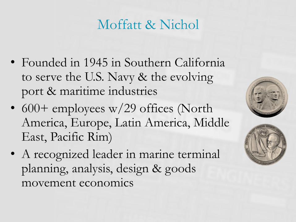
Moffatt & Nichol
• Founded in 1945 in Southern California to serve the U.S. Navy & the evolving port & maritime industries
• 600+ employees w/29 offices (North America, Europe, Latin America, Middle East, Pacific Rim)
• A recognized leader in marine terminal planning, analysis, design & goods movement economics

Services for Development of Automated
Terminal Matrix
3
ServicesMoffatt & Nichol
TypicalSimulation Consultant
Typical Infrastructure
Consultant
Typical Equipment
VendorMaster Planning
Investment Advisory
Basis of Design
Simulation
Interface Plan
Equipment Specifications
IT, Application Specifications
Design (infrastructure)
Procurement Process:Equipment
IT, Application
Program Management (infrastructure)
Contract Management (equipment)
Emulation
Training
Go-Live Support
Optimization

The Business Case
4
Environmentally sustainable (lowest energy consumption)
Efficient(delivering capacity, speed and reliability at lowest cost)
E3
Economical(meeting the business case)

Planning and Layout – Tailoring to Fit the BC
• So, the planner is like a tailor
• He must try to fashion the terminal to fit the business case perfectly
• One size does not fit all!
5
CAPACITY
• Annual throughput
PRODUCTIVITY
• Vessel
• Gate
• Rail
COST
• Facilities
• Equipment
• Labor
• Energy

Operations
Logistics
Infrastructure
Equipment
Traditional
Conventional “Bottom-Up” Planning

Operations
Logistics
Infrastructure
Equipment
New
New “Top-Down” Planning

Program Integration
Team
Coordinate:
Operations–Infrastructure
Infrastructure
Wharf Buildings
Backlands Elect/Comm
Rail Gate
Project ManagerReporting
Cost Control Schedule Control
Operations
Terminal
Ops TOS IT Equip Maint
Systems & Process Integrator
Executive / Steering
Committee
Core team
Project Organization?

Development Philosophy
• The infrastructure for an automated terminal is
fixed for its economic life
• An automated container terminal will be designed
to perform under high utilization
• It is critical to predict performance and operating
cost for the life of the infrastructure
• An early preparation of well-integrated, long-term
masterplan and development plan is required

Path to Completion is Complex

Wharf
Robotic Operation
Manned Main Trolley
Automated Secondary
Trolley
Automated Horizontal TransportAGV’s
Container Yard
Automated Container Stacking, Retrieval, ShufflingASC’s
Semi-Automated Delivery to
Outside Truck
Vessel Outside Truck
Quay Crane

12
Wharf Design Issues

Wharf Design Issue
• Quay design load will depend on crane:
• Gage
• Back reach
• Out reach
• Setback from face of the quay
• Type of operation (tandem, single, double trolley etc.)
• Wind and seismic load
• Crane wharf interaction
13

Seismic Design Approach
• Performance-based design approach:
– Operating Level Earthquake (OLE)
– Contingency Level Earthquake (CLE)
– Code-Level Design Earthquake (DE)
• Performance goals:
– OLE performance = No damage
– CLE performance = Repairable damage
– DE performance = No collapse

Berthing and Mooring Loads
• Berthing Load– Design Vessel 20,000 TEU +
– Ship Approach Velocity and Angle 0.26 ft/s , 5o
– Length Overall (LOA) 1,300 feet +
– Maximum Displacement 254,000 metric tons +
– Beam 194 feet
– Maximum Draft 50.8 feet
– Allowable Hull Pressure 4.13 ksf
• Mooring Load– 200 metric ton bollards

Horizontal Transport Area
Robotic Operation
Manned Main Trolley
Automated Secondary
Trolley
Automated Horizontal TransportAGV’s
Container Yard
Automated Container Stacking, Retrieval, ShufflingASC’s
Semi-Automated Delivery to
Outside Truck
Vessel Outside Truck
Quay Crane

Horizontal Transport
• Gathering and distributing
tasks to/from storage
– Move any box, from any
location to any location at any
time
• Must be rubber-tired
– AGV/L-AGV (diesel/ battery
operated)
– AShC/AStraddle (hybrid diesel)
17

Typical AGV Traffic Layout
• It is important to understand the traffic pattern
• Operationally acceptable grades
• Requirements for systems such as transponders and magnets
• Appropriate position for all above ground structures
18
6 long travel lanes
Cross-traveland holding lanes
6 transfer lanes
LS QC rail
1 long travel lane

WS Transfer Area
• Understand the operational requirements
• Interface with AGV system
• Interface with ASC control/ safety systems
• Load repetition
• Durability of pavement
• Different solutions for different modes of
operation
19

Pavement Areas

Berth 1 Berth 2 Berth 3
Berth 1 Favored
Area
Berth 2 Favored
Area
Berth 3 Favored
Area
Vehicle / Wheel Load Repetition
Favored Storage Location
21

Vehicle / Wheel Load RepetitionContainer Location Distribution
0.0%
2.0%
4.0%
1 2 3 4 5 6 7 8 9 10 11 12 13 14 15 16 17 18 19 20 21 22 23 24 25 26 27 28 29 30 31 32 33 34 35 36 37
Block Index
Equal Storage
0.0%
1.0%
2.0%
3.0%
4.0%
1 2 3 4 5 6 7 8 9 10 11 12 13 14 15 16 17 18 19 20 21 22 23 24 25 26 27 28 29 30 31 32 33 34 35 36 37
Block Index
Proportional Storage
0.0%
1.0%
2.0%
3.0%
4.0%
5.0%
6.0%
7.0%
1 2 3 4 5 6 7 8 9 10 11 12 13 14 15 16 17 18 19 20 21 22 23 24 25 26 27 28 29 30 31 32 33 34 35 36 37
Block Index
60% to Favored Storage
Berth Location 8 - 20 Berth Location 21 - 31 Berth Location 32 - >37

Vehicle / Wheel RepetitionResults – Equal Storage Case
• Max Reps at middle of blocks
• 1M reps ~ 55% of terminal throughput
0
200,000
400,000
600,000
800,000
1,000,000
1,200,000
1 2 3 4 5 6 7 8 9 10 11 12 13 14 15 16 17 18 19 20 21 22 23 24 25 26 27 28 29 30 31 32 33 34 35 36 37
Block Index
Loaded Vehicle Repetition at Various Locations(Equal Storage Case)

Vehicle / Wheel RepetitionProportional Storage Case
• Max Reps at middle of blocks
• 1M reps ~ 55% of terminal throughput
0
200,000
400,000
600,000
800,000
1,000,000
1,200,000
1 2 3 4 5 6 7 8 9 10 11 12 13 14 15 16 17 18 19 20 21 22 23 24 25 26 27 28 29 30 31 32 33 34 35 36 37
Block Index
Loaded Vehicle Repetition at Various Locations(Proportional Storage Case)

Vehicle / Wheel RepetitionFavored Storage Case
• Max Reps flattened and reduced
• 0.65M reps ~ 35% of terminal throughput
0
100,000
200,000
300,000
400,000
500,000
600,000
700,000
1 2 3 4 5 6 7 8 9 10 11 12 13 14 15 16 17 18 19 20 21 22 23 24 25 26 27 28 29 30 31 32 33 34 35 36 37
Block Index
Loaded Vehicle Repetition at Various Locations(80% Favored Storage Case)

Vehicle / Wheel Repetition
Summary of Result
Allocation Assumptions
Equal Storage
Proportional Storage
Favored Storage
Worst Case40% 50% 60% 70% 80%
Max Vehicle Repetition (Loaded) 998,746 1,005,520 973,410 891,698 809,986 728,275 646,563 1,005,520
Block Location When Max Repetition Takes Place 23 19 19 19 19 19 19 19Percentage of Throughput 54% 55% 53% 49% 44% 40% 35% 55%
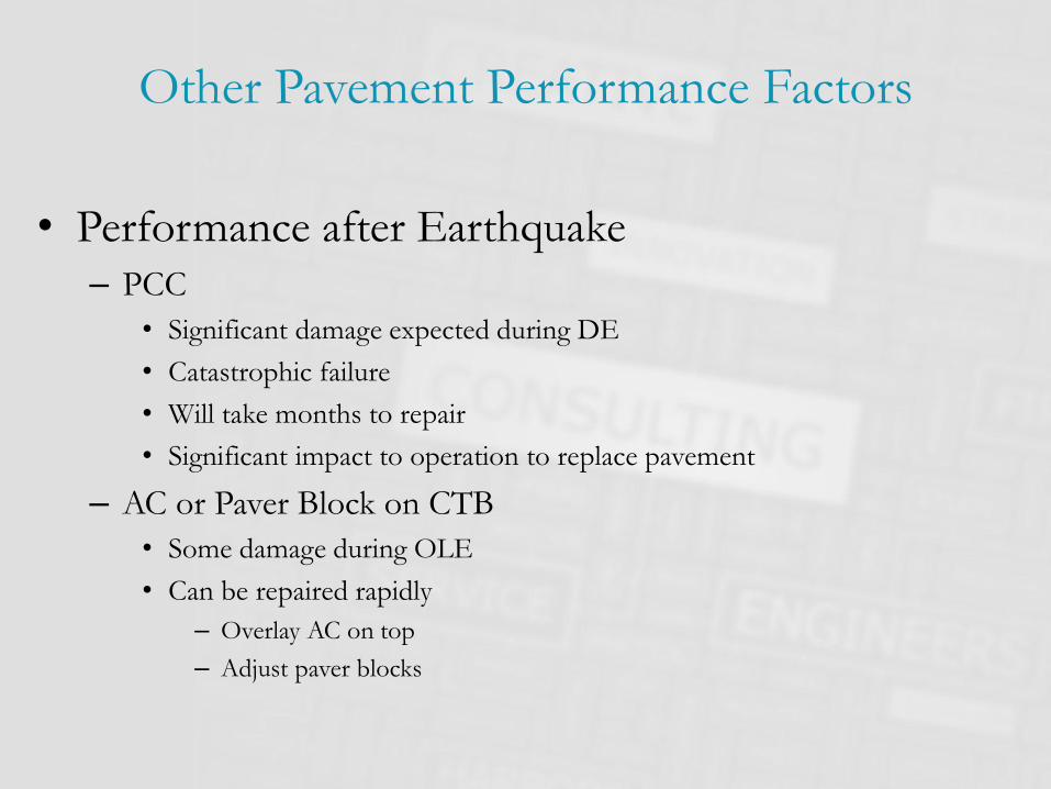
Other Pavement Performance Factors
• Performance after Earthquake
– PCC
• Significant damage expected during DE
• Catastrophic failure
• Will take months to repair
• Significant impact to operation to replace pavement
– AC or Paver Block on CTB
• Some damage during OLE
• Can be repaired rapidly
– Overlay AC on top
– Adjust paver blocks

Other Pavement Performance Factors
• Transponder Installation for AGV
– App. 20 mm in diameter, 50 mm long (2 inches) glass body sealed
with foam cushioning
– Insert in holes 25 mm in diameter, 80 mm (3 inches) deep, sealed
with glue
– Leaving 0.5 inch gap between transponder and RCC pave for 3-
inch AC
• 3-inch AC if rutted, damage on Transponder?
3” AC
CTB or RCC
0.5”
2”
0.5”

Other Pavement Performance Factors
• Rescue of Automated Equipment
– Typical rescue method
for AGV
• Reach stackers
• Permanent damage to pavement
– Alternative rescue method
• By terminal trucks with “gooseneck”
• Lighter wheel load
29

Comparative Cost
• Life Cycle Cost Summary
78% 70% 76% 76% 100% 100% 97% 97%
$0.00
$20.00
$40.00
$60.00
$80.00
$100.00
$120.00
$140.00
SHC AGV SHC AGV SHC AGV SHC AGV SHC & AGV
Asphalt on CTB Asphalt on RCC Reinforced PCC Paver Block Reinforced PCC
Waterside Traffic Area Waterside Transfer
AreaLowest

Automated Stacking Area
Robotic Operation
Manned Main Trolley
Automated Secondary
Trolley
Automated Horizontal TransportAGV’s
Container Yard
Automated Container Stacking, Retrieval, ShufflingASC’s
Semi-Automated Delivery to
Outside Truck
Vessel Outside Truck
Quay Crane

Container yard
• End-loaded stacking/retrieval
cranes
• Side-loaded stacking/retrieval
with landside transfer cranes
32

Why Low Tolerance?

Why Low Tolerance?

1.5‘
~ 4“
Why Low Tolerance?

Well Consolidated Landfill
• Critical to minimize total and differential
settlements due to:
–Dynamic loads created by crane operation
– Stacked container storage
– Impact loads from container stacks
36

Drainage
• Stacking area flat and drainable
• Drainage and storm water treatment
– Design slope that meets operational requirements
– Comply with local regulation in treating storm water
37

Other Utilities
• Fresh water supply
• Sanitary sewer
• Light poles (do we need
any?)
• Antenna poles
• Camera poles
• Fencing
• X-ray inspection
(VACIS)
• Fire protection
• Security systems
38

Power System
• Redundancy
• 100% fault tolerance
• Reliable
• Location and size of
substations, transformer
• Each crane in same stack
energized from two
independent sources
39

Design Issues ASC Blocks
• RMG rails and beams
• Reefers
• Hazardous
• Grading and drainage
40

Reefer Racks
• Clear understanding of
operational requirements
• Consider all safety
requirements
• Understand the access
control and interfaces with
crane system
• Comply with building
requirements
41

ASC Runway
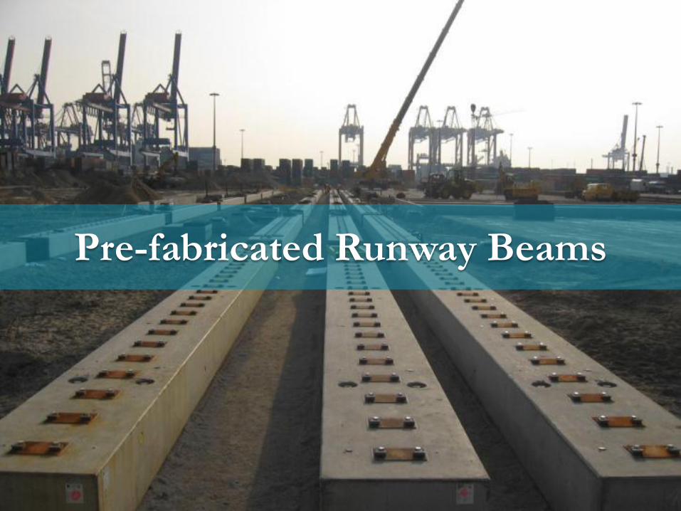
Planning, Design & Implementation of Automated Terminals
Pre-fabricated Runway Beams

ASC Runway

Land Side Transfer Area
Robotic Operation
Manned Main Trolley
Automated Secondary
Trolley
Automated Horizontal TransportAGV’s
Container Yard
Automated Container Stacking, Retrieval, ShufflingASC’s
Semi-Automated Delivery to
Outside Truck
Vessel Outside Truck
Quay Crane

Landside Transfer Area
• Understand the
operational requirements
• Interface with gate
systems
• Interface with ASC
control/ safety systems
• Load repetition
• Durability of pavement
46

Landside Transfer Area
• Truck maneuvering to
the transfer area
• Use island to locate
electrical substations
and communication
hub building
47

Intermodal Rail Area
Robotic Operation
Manned Main Trolley
Automated Secondary
Trolley
Automated Horizontal TransportAGV’s
Container Yard
Automated Container Stacking, Retrieval, ShufflingASC’s
Semi-Automated Delivery to
Outside Truck
Vessel Outside Truck
Quay Crane

IY Area
• On dock rail
• Designed for efficient rail loading operations
– Semi-automated remotely operated rail loading cranes
– Safety fence and gate locations and access control
– The right crane rail
49

Planning, Design & Implementation of Automated Terminals
50
Rail operation
Rail Operation

Buildings
• Gates
– Highly automated
– RFID for truck identification
– OCR
– TWIC reader for security
– Truck holding areas
• Administration/Operation/
IT
– House IT systems
– Remote operator’s room(s)
– Other operation
• Maintenance
— Provide sufficient storage for
spare parts
— Almost all electrical equipment
— Almost all maintenance is
performed at the equipment
site, not in the workshop
— Connected to IT systems
— Location depends on
— Mode of waterside transport
— Mode of fueling (battery/diesel)
• Battery Exchange Building
51

Planning, Design & Implementation of Automated Terminals
52
Robotic battery changing station
Robotic Battery Changing Station

Example of Operations Control Room
• Orientation
• Windows
• Light
• Noise
• Table space
53

Integration Management
• An automated terminal is a highly integrated system
of components that must fit together perfectly
• The only standard is the container
54
THIS IS WHERE PROJECTS TYPICALLY
SUCCEED OR FAIL

Thank You
55