Planning and Calculation - kesko-onninen-pim-resources...
32
Planning and Calculation Planning and Calculation Selection of the most suitable products for pressure maintenance, degassing and water make-up
Transcript of Planning and Calculation - kesko-onninen-pim-resources...
Planning and Calculation
Planning and CalculationSelection of the most suitable products for pressure maintenance, degassing and water make-up

IMI PNEUMATEX / Planning and Calculation /
2
3
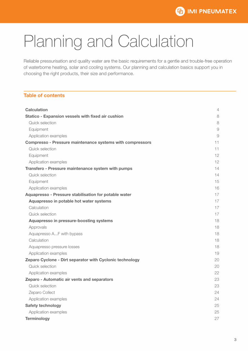
Planning and CalculationReliable pressurisation and quality water are the basic requirements for a gentle and trouble-free operation of waterborne heating, solar and cooling systems. Our planning and calculation basics support you in choosing the right products, their size and performance.
Table of contents
Calculation 4
Statico - Expansion vessels with fixed air cushion 8
Quick selection 8
Equipment 9
Application examples 9
Compresso - Pressure maintenance systems with compressors 11
Quick selection 11
Equipment 12
Application examples 12
Transfero - Pressure maintenance system with pumps 14
Quick selection 14
Equipment 15
Application examples 16
Aquapresso - Pressure stabilisation for potable water 17
Aquapresso in potable hot water systems 17
Calculation 17
Quick selection 17
Aquapresso in pressure-boosting systems 18
Approvals 18
Aquapresso A...F with bypass 18
Calculation 18
Aquapresso pressure losses 18
Application examples 19
Zeparo Cyclone - Dirt separator with Cyclonic technology 20
Quick selection 20
Application examples 22
Zeparo - Automatic air vents and separators 23
Quick selection 23
Zeparo Collect 24
Application examples 24
Safety technology 25
Application examples 25
Terminology 27
IMI PNEUMATEX / Planning and Calculation / Planning and Calculation
4
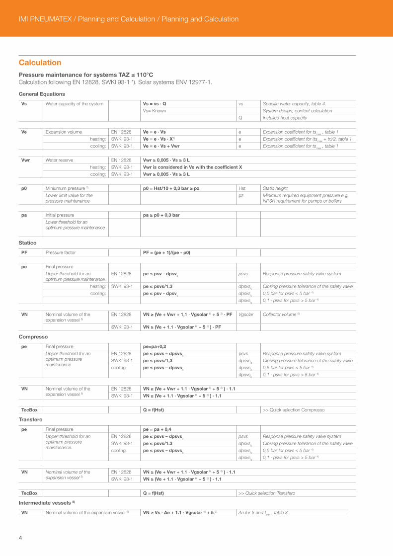
CalculationPressure maintenance for systems TAZ ≤ 110°CCalculation following EN 12828, SWKI 93-1 *). Solar systems ENV 12977-1.
General Equations
Vs
Water capacity of the system
Vs = vs · Q vs Specific water capacity, table 4.
Vs= Known System design, content calculation
Q Installed heat capacity
Ve
Expansion volume EN 12828 Ve = e · Vs e Expansion coefficient for tsmax , table 1
heating: SWKI 93-1 Ve = e · Vs · X1) e Expansion coefficient for (tsmax + tr)/2, table 1
cooling: SWKI 93-1 Ve = e · Vs + Vwr e Expansion coefficient for tsmax , table 1
Vwr
Water reserve EN 12828 Vwr ≥ 0,005 · Vs ≥ 3 L
heating: SWKI 93-1 Vwr is considered in Ve with the coefficient X
cooling: SWKI 93-1 Vwr ≥ 0,005 · Vs ≥ 3 L
p0
Miniumum pressure 2) p0 = Hst/10 + 0,3 bar ≥ pz Hst Static height
Lower limit value for the pressure maintenance
pz Minimum required equipment pressure e.g. NPSH requirement for pumps or boilers
pa
Initial pressure pa ≥ p0 + 0,3 bar
Lower threshold for an optimum pressure maintenance
Statico
PF Pressure factor PF = (pe + 1)/(pe - p0)
pe
Final pressure
Upper threshold for an optimum pressure maintenance.
EN 12828 pe ≤ psv - dpsvc psvs Response pressure safety valve system
heating: SWKI 93-1 pe ≤ psvs/1.3 dpsvsc Closing pressure tolerance of the safety valve
cooling: pe ≤ psv - dpsvc dpsvsc 0,5 bar for psvs ≤ 5 bar 4)
dpsvsc 0,1 · psvs for psvs > 5 bar 4)
VN
Nominal volume of the expansion vessel 5)
EN 12828 VN ≥ (Ve + Vwr + 1,1 · Vgsolar 6) + 5 3) · PF Vgsolar Collector volume 6)
SWKI 93-1 VN ≥ (Ve + 1.1 · Vgsolar 6) + 5 3) ) · PF
Compresso
pe
Final pressure pe=pa+0,2
Upper threshold for an optimum pressure maintenance
EN 12828 pe ≤ psvs – dpsvsc psvs Response pressure safety valve system
SWKI 93-1 pe ≤ psvs/1,3 dpsvsc Closing pressure tolerance of the safety valve
cooling
pe ≤ psvs – dpsvsc
dpsvsc 0,5 bar for psvs ≤ 5 bar 4)
dpsvsc 0,1 · psvs for psvs > 5 bar 4)
VN
Nominal volume of the expansion vessel 5)
EN 12828 VN ≥ (Ve + Vwr + 1.1 · Vgsolar 6) + 5 3) ) · 1.1
SWKI 93-1 VN ≥ (Ve + 1.1 · Vgsolar 6) + 5 3) ) · 1.1
TecBox Q = f(Hst) >> Quick selection Compresso
Transfero
pe
Final pressure pe = pa + 0,4
Upper threshold for an optimum pressure maintenance.
EN 12828 pe ≤ psvs – dpsvsc psvs Response pressure safety valve system
SWKI 93-1 pe ≤ psvs/1.3 dpsvsc Closing pressure tolerance of the safety valve
cooling pe ≤ psvs – dpsvsc dpsvsc 0,5 bar for psvs ≤ 5 bar 4)
dpsvsc 0,1 · psvs for psvs > 5 bar 4)
VN
Nominal volume of the expansion vessel 5)
EN 12828 VN ≥ (Ve + Vwr + 1.1 · Vgsolar 6) + 5 3) ) · 1.1
SWKI 93-1 VN ≥ (Ve + 1.1 · Vgsolar 6) + 5 3) ) · 1.1
TecBox Q = f(Hst) >> Quick selection Transfero
Intermediate vessels 5)
VN Nominal volume of the expansion vessel 5) VN ≥ Vs · Δe + 1.1 · Vgsolar 6) + 5 3) ∆e for tr and tmin , table 3

5
1) Q ≤ 30 kW: X = 3 | 30 kW < Q ≤ 150 kW: X = 2 | Q > 150 kW: X = 1,52) The formula for the minimum pressure p0 applies to the installation of the pressure maintenance on the suction side of the circulation pump. In case of a pressure-side installation p0 is to be increased by the pump pressure ∆p.3) Add 5 litre when a Vento is installed in the system.4) The safety valves must work within these limits.5) Please select a vessel which has an equal or higher nominal content.6) In solar systems to ENV12977-1: collector volume VK that can evaporate when not in operation; otherwise VK = 0.*) SWKI 93-1: Valid for Switzerland
Our calculation program HySelect is based on an advanced calculation method and data base. Therefore results may deviate.
Table 1: e expansion coefficient
t (TAZ, tsmax, tr, tsmin), °C 20 30 40 50 60 70 80 90 100 105 110
e Water = 0°C 0,0016 0,0041 0,0077 0,0119 0,0169 0,0226 0,0288 0,0357 0,0433 0,0472 0,0513 e % weight MEG* 30% = -14,5°C 0,0093 0,0129 0,0169 0,0224 0,0286 0,0352 0,0422 0,0497 0,0577 0,0620 0,066340% = -23,9°C 0,0144 0,0189 0,0240 0,0300 0,0363 0,0432 0,0505 0,0582 0,0663 0,0706 0,075050% = -35,6°C 0,0198 0,0251 0,0307 0,0370 0,0437 0,0507 0,0581 0,0660 0,0742 0,0786 0,0830e % weight MPG**
30% = -12,9°C 0,0151 0,0207 0,0267 0,0333 0,0401 0,0476 0,0554 0,0639 0,0727 0,0774 0,082340% = -20,9°C 0,0211 0,0272 0,0338 0,0408 0,0481 0,0561 0,0644 0,0731 0,0826 0,0873 0,092450% = -33,2°C 0,0288 0,0355 0,0425 0,0500 0,0577 0,0660 0,0747 0,0839 0,0935 0,0985 0,1036
Table 2: pv vapour over-pressure (bar)
TAZ, °C 105 110
pv Water 0,1948 0,4196 pv % weight MEG* 30% 0,1793 0,386440% 0,1671 0,360150% 0,1523 0,3284pv % weight MPG** 30% 0,1938 0,417640% 0,1938 0,417550% 0,1938 0,4174
Table 3: Δe expansion (in chilled water systems when tr < 5°C; in heating systems when tr > 70°C)
tr, °C -35 -30 -25 -20 -15 -10 -5 0 80 90 100 105 110
Δe Water = 0°C - - - - - - - - - 0,0062 0,0131 0,0207 0,0246 0,0287 Δe % weight MEG* 30% = -14,5°C - - - - - 0,0032 0,0023 0,0012 - 0,0070 0,0145 0,0226 0,0269 0,031240% = -23,9°C - - - 0,0081 0,0069 0,0055 0,0038 0,0019 - 0,0073 0,0150 0,0231 0,0274 0,031850% = -35,6°C 0,0131 0,0121 0,0109 0,0094 0,0076 0,0056 0,0038 0,0019 - 0,0075 0,0154 0,0236 0,0279 0,0324Δe % weight MPG** 30% = -12,9°C - - - - - 0,0068 0,0045 0,0023 - 0,0078 0,0163 0,0252 0,0298 0,034740% = -20,9°C - - - 0,0125 0,0099 0,0077 0,0052 0,0026 - 0,0083 0,0170 0,0265 0,0313 0,036350% = -33,2°C - 0,0187 0,0162 0,0137 0,0111 0,0086 0,0058 0,0029 - 0,0088 0,0179 0,0276 0,0325 0,0376
Table 4: vs approx. water capacity *** of central heatings referred to the installed heat capacity Q
tsmax | tr °C 90 | 70 80 | 60 70 | 55 70 | 50 60 | 40 50 | 40 40 | 30 35| 28
Radiators vs liter/kW 14,0 16,5 20,1 20,6 27,9 36,6 - -Flat radiators vs liter/kW 9,0 10,1 12,1 11,9 15,1 20,1 - -Convectors vs liter/kW 6,5 7,0 8,4 7,9 9,6 13,4 - -Air handlers vs liter/kW 5,8 6,1 7,2 6,6 7,6 10,8 - -Floor heating vs liter/kW 10,3 11,4 13,3 13,1 15,8 20,3 29,1 37,8
*) MEG = Mono-Ethylene Glycol**) MPG = Mono-Propylene Glycol***) Water capacity = heat generator + distribution net + heat emitters
IMI PNEUMATEX / Planning and Calculation / Planning and Calculation
6
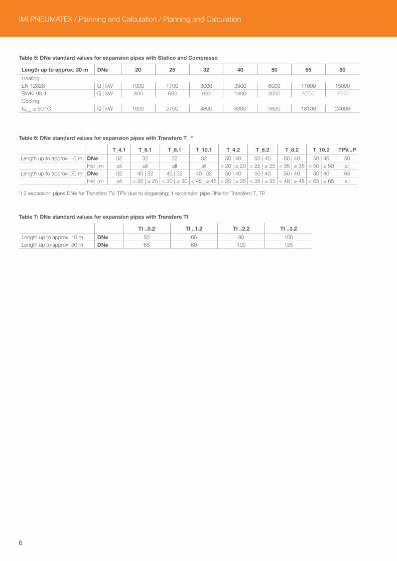
Table 5: DNe standard values for expansion pipes with Statico and Compresso
Length up to approx. 30 m DNe 20 25 32 40 50 65 80
Heating: EN 12828 Q | kW 1000 1700 3000 3900 6000 11000 15000SWKI 93-1 Q | kW 300 600 900 1400 3000 6000 9000Cooling: tsmax ≤ 50 °C Q | kW 1600 2700 4800 6300 9600 18100 24600
Table 6: DNe standard values for expansion pipes with Transfero T_ *
T_4.1 T_6.1 T_8.1 T_10.1 T_4.2 T_6.2 T_8.2 T_10.2 TPV...P
Length up to approx. 10 m DNe 32 32 32 32 50 | 40 50 | 40 50 | 40 50 | 40 50 Hst | m all all all all < 20 | ≥ 20 < 25 | ≥ 25 < 35 | ≥ 35 < 50 | ≥ 50 allLength up to approx. 30 m DNe 32 40 | 32 40 | 32 40 | 32 50 | 40 50 | 40 50 | 40 50 | 40 65 Hst | m all < 25 | ≥ 25 < 30 | ≥ 30 < 45 | ≥ 45 < 25 | ≥ 25 < 35 | ≥ 35 < 48 | ≥ 48 < 65 | ≥ 65 all
*) 2 expansion pipes DNe for Transfero TV, TPV due to degassing; 1 expansion pipe DNe for Transfero T, TP.
Table 7: DNe standard values for expansion pipes with Transfero TI
TI ..0.2 TI ..1.2 TI ..2.2 TI ..3.2
Length up to approx. 10 m DNe 50 65 80 100Length up to approx. 30 m DNe 65 80 100 125
7
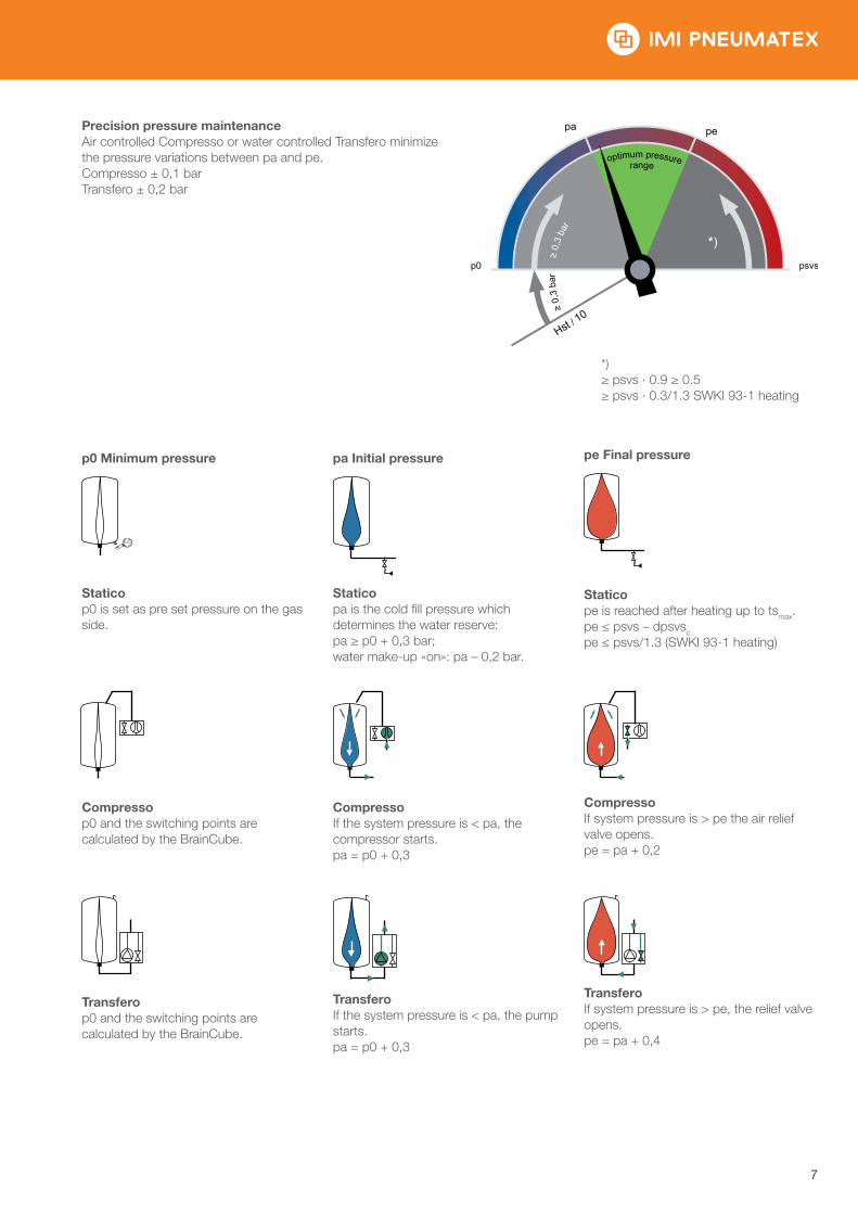
Precision pressure maintenanceAir controlled Compresso or water controlled Transfero minimize the pressure variations between pa and pe.Compresso ± 0,1 barTransfero ± 0,2 bar
*) ≥ psvs · 0.9 ≥ 0.5 ≥ psvs · 0.3/1.3 SWKI 93-1 heating
p0 Minimum pressure
Staticop0 is set as pre set pressure on the gas side.
Compressop0 and the switching points are calculated by the BrainCube.
Transferop0 and the switching points are calculated by the BrainCube.
pa Initial pressure
Staticopa is the cold fill pressure which determines the water reserve:pa ≥ p0 + 0,3 bar; water make-up «on»: pa – 0,2 bar.
CompressoIf the system pressure is < pa, the compressor starts.pa = p0 + 0,3
k
TransferoIf the system pressure is < pa, the pump starts.pa = p0 + 0,3
pe Final pressure
Statico pe is reached after heating up to tsmax. pe ≤ psvs – dpsvsc pe ≤ psvs/1.3 (SWKI 93-1 heating)
CompressoIf system pressure is > pe the air relief valve opens.pe = pa + 0,2
TransferoIf system pressure is > pe, the relief valve opens.pe = pa + 0,4
Hst / 10
≥ 0,
3 ba
r
≥ 0
,3 b
ar
optimum pressure
psvsp0
pa pe
*)
range
IMI PNEUMATEX / Planning and Calculation / Planning and Calculation
8
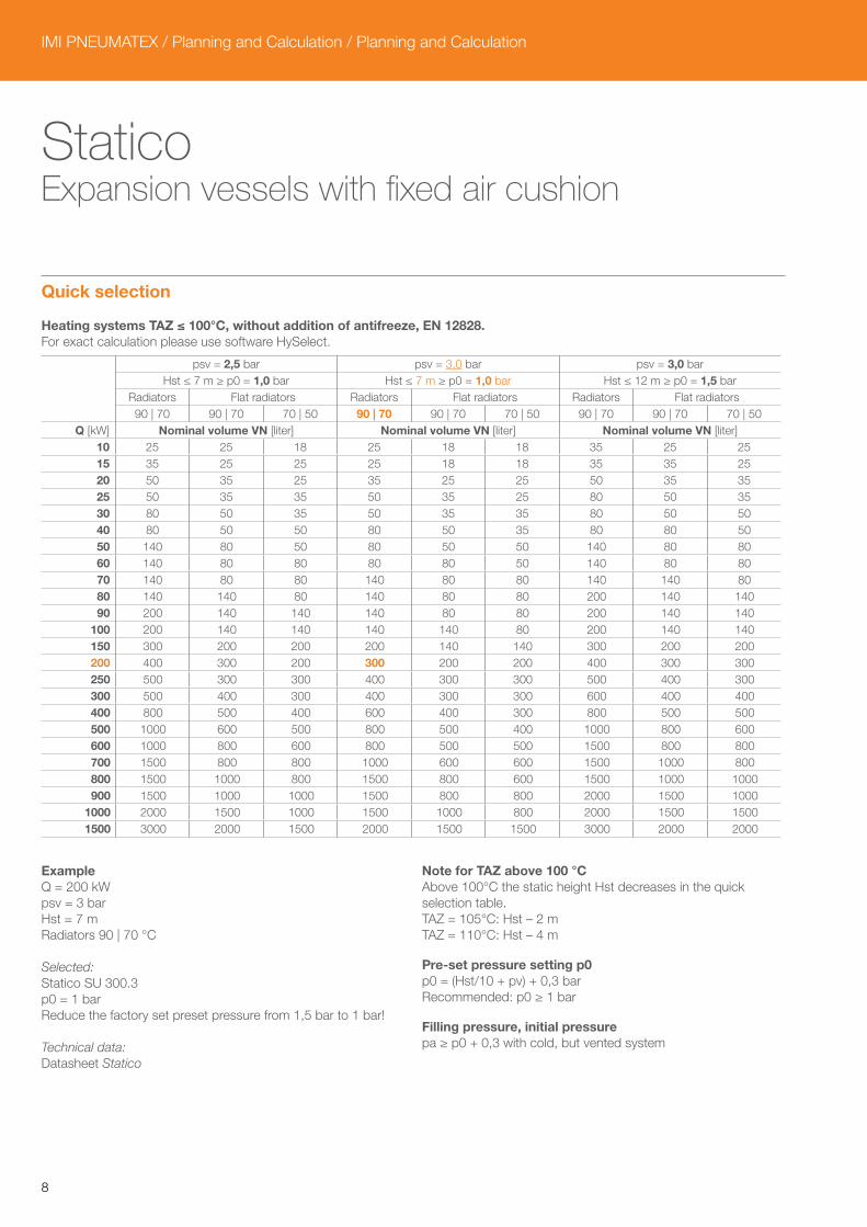
Statico Expansion vessels with fixed air cushion
Quick selection
Heating systems TAZ ≤ 100°C, without addition of antifreeze, EN 12828.For exact calculation please use software HySelect.
psv = 2,5 bar psv = 3,0 bar psv = 3,0 bar Hst ≤ 7 m ≥ p0 = 1,0 bar Hst ≤ 7 m ≥ p0 = 1,0 bar Hst ≤ 12 m ≥ p0 = 1,5 bar Radiators Flat radiators Radiators Flat radiators Radiators Flat radiators 90 | 70 90 | 70 70 | 50 90 | 70 90 | 70 70 | 50 90 | 70 90 | 70 70 | 50
Q [kW] Nominal volume VN [liter] Nominal volume VN [liter] Nominal volume VN [liter] 10 25 25 18 25 18 18 35 25 2515 35 25 25 25 18 18 35 35 2520 50 35 25 35 25 25 50 35 3525 50 35 35 50 35 25 80 50 3530 80 50 35 50 35 35 80 50 5040 80 50 50 80 50 35 80 80 5050 140 80 50 80 50 50 140 80 8060 140 80 80 80 80 50 140 80 8070 140 80 80 140 80 80 140 140 8080 140 140 80 140 80 80 200 140 14090 200 140 140 140 80 80 200 140 140
100 200 140 140 140 140 80 200 140 140150 300 200 200 200 140 140 300 200 200200 400 300 200 300 200 200 400 300 300250 500 300 300 400 300 300 500 400 300300 500 400 300 400 300 300 600 400 400400 800 500 400 600 400 300 800 500 500500 1000 600 500 800 500 400 1000 800 600600 1000 800 600 800 500 500 1500 800 800700 1500 800 800 1000 600 600 1500 1000 800800 1500 1000 800 1500 800 600 1500 1000 1000900 1500 1000 1000 1500 800 800 2000 1500 1000
1000 2000 1500 1000 1500 1000 800 2000 1500 15001500 3000 2000 1500 2000 1500 1500 3000 2000 2000
ExampleQ = 200 kWpsv = 3 barHst = 7 mRadiators 90 | 70 °C
Selected:Statico SU 300.3p0 = 1 barReduce the factory set preset pressure from 1,5 bar to 1 bar!
Technical data:Datasheet Statico
Note for TAZ above 100 °CAbove 100°C the static height Hst decreases in the quick selection table.TAZ = 105°C: Hst – 2 mTAZ = 110°C: Hst – 4 m
Pre-set pressure setting p0p0 = (Hst/10 + pv) + 0,3 barRecommended: p0 ≥ 1 bar
Filling pressure, initial pressurepa ≥ p0 + 0,3 with cold, but vented system
9
Equipment
Lock shield valve DLVSecured lock shield valve with draining for expansion vessels according to EN 12828, DLV 20 up to VN 800 litres, DN 40 for VN 1000 – 5000 litres to be locally supplied.
Expansion pipeAccording to table 5.
PlenoWater make-up as pressure maintenance monitoring device according to EN 12828.Conditions:• Pleno PI without pump: required fresh water pressure: pw ≥ p0 + 1,5 | pw ≤ 10 bar,• Pleno PI 6, PI 9 with pump: pa Statico within the working pressure range dpu of the Pleno.
VentoDegassing and central venting.Conditions:• pe, pa Statico within the working pressure range dpu of the Vento,• Vs Vento ≥ Vs water capacity of the system.
ZeparoAir vent Zeparo ZUT, ZUTX or ZUP at each high point for venting during the filling and during the draining process. Separator for dirt and magnetite in each system in the main return to the heat generator. If no central degassing (e.g. Vento or Compresso CPV) is installed a micro bubble separator can be installed in the main flow if possible before the circulation pump.The static height, Hstm, according to the following table above the micro bubble separators, must not be exceeded.
tsmax | °C 90 80 70 60 50 40 30 20 10
Hstm | m 15,0 13,4 11,7 10,0 8,4 6,7 5,0 3,3 1,7
Further accessories, product and selection details:Datasheets Pleno, Vento, Zeparo and Accessories.
Application examples
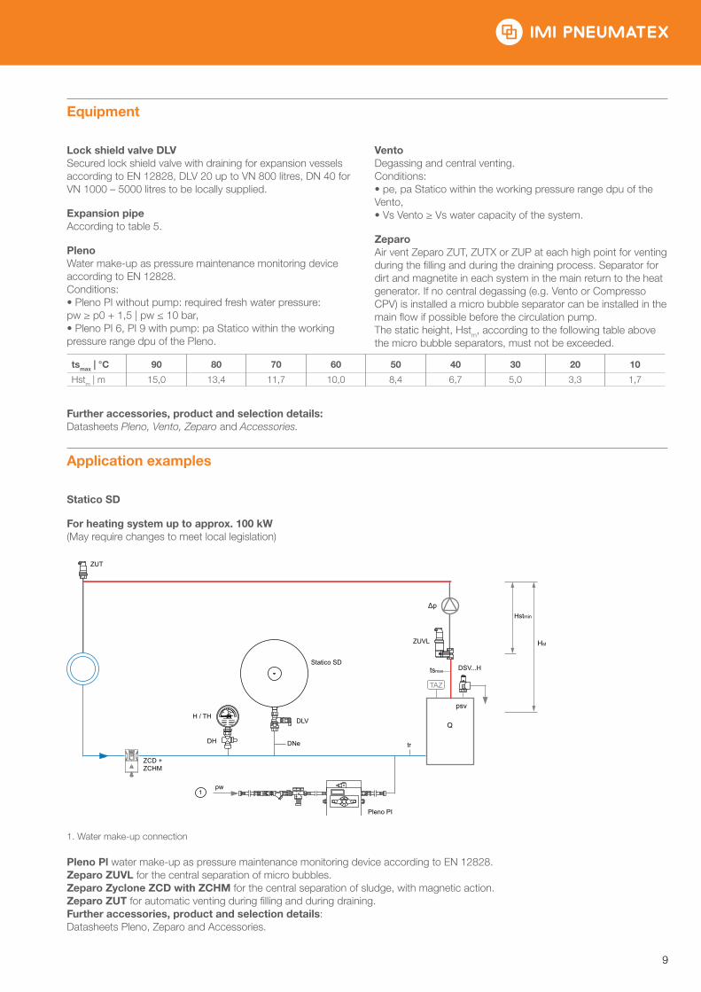
Statico SD
For heating system up to approx. 100 kW(May require changes to meet local legislation)
1. Water make-up connection
Pleno Pl water make-up as pressure maintenance monitoring device according to EN 12828.Zeparo ZUVL for the central separation of micro bubbles.Zeparo Zyclone ZCD with ZCHM for the central separation of sludge, with magnetic action.Zeparo ZUT for automatic venting during filling and during draining.Further accessories, product and selection details:Datasheets Pleno, Zeparo and Accessories.
ZUT
ZCD + ZCHM
H / TH
DH
Statico SD
DLV
DNe
Pleno PI
tr
Q
psv
Δp
ZUVL
tsmax DSV...H
Hstmin
Hst
pw1
IMI PNEUMATEX / Planning and Calculation / Planning and Calculation
10
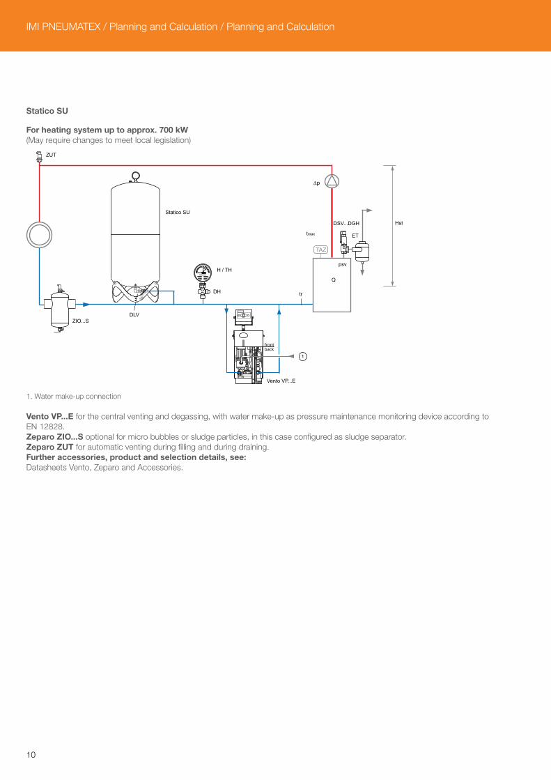
Statico SU
For heating system up to approx. 700 kW(May require changes to meet local legislation)
1. Water make-up connection
Vento VP...E for the central venting and degassing, with water make-up as pressure maintenance monitoring device according to EN 12828.Zeparo ZIO...S optional for micro bubbles or sludge particles, in this case configured as sludge separator.Zeparo ZUT for automatic venting during filling and during draining.Further accessories, product and selection details, see:Datasheets Vento, Zeparo and Accessories.
ZUT
ZIO...SDLV
Statico SU
H / TH
Q
psv
tmax
∆p
DSV...DGH
ET
Hst
tr
Vento VP...E
DH
1
11
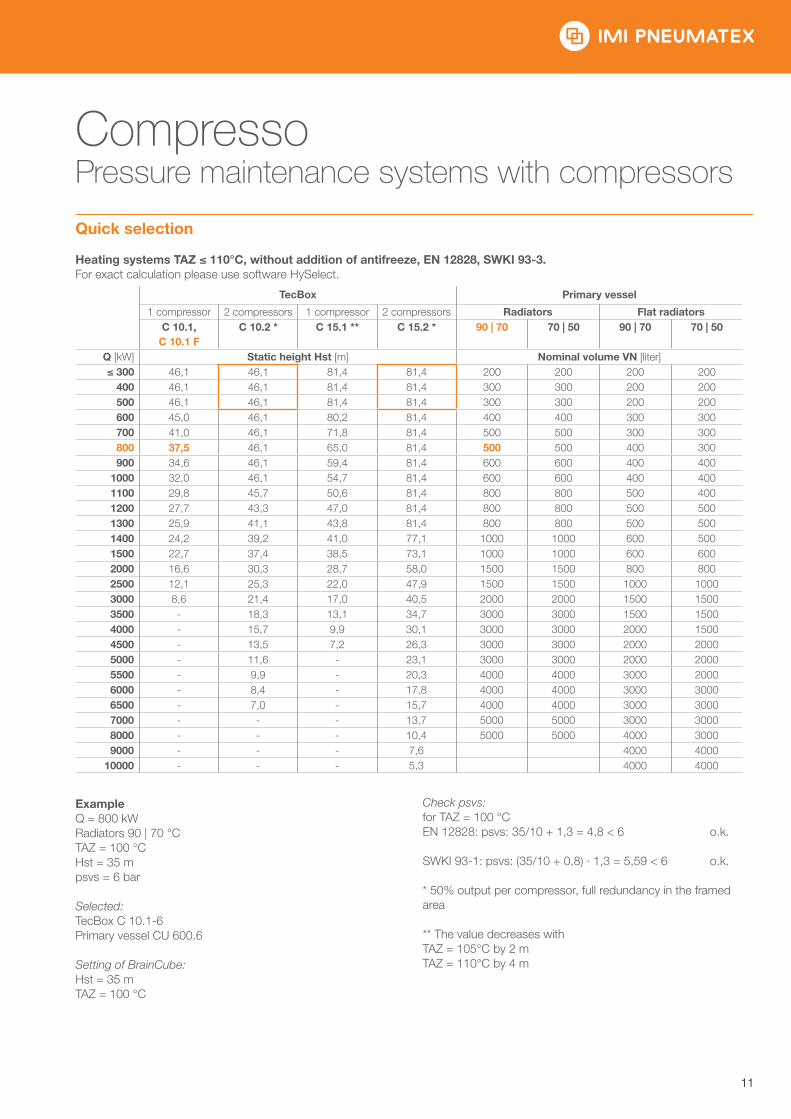
Compresso Pressure maintenance systems with compressors
Quick selection
Heating systems TAZ ≤ 110°C, without addition of antifreeze, EN 12828, SWKI 93-3.For exact calculation please use software HySelect.
TecBox Primary vessel
1 compressor 2 compressors 1 compressor 2 compressors Radiators Flat radiators C 10.1,
C 10.1 F C 10.2 * C 15.1 ** C 15.2 * 90 | 70 70 | 50 90 | 70 70 | 50
Q [kW] Static height Hst [m] Nominal volume VN [liter] ≤ 300 46,1 46,1 81,4 81,4 200 200 200 200
400 46,1 46,1 81,4 81,4 300 300 200 200500 46,1 46,1 81,4 81,4 300 300 200 200600 45,0 46,1 80,2 81,4 400 400 300 300700 41,0 46,1 71,8 81,4 500 500 300 300800 37,5 46,1 65,0 81,4 500 500 400 300900 34,6 46,1 59,4 81,4 600 600 400 400
1000 32,0 46,1 54,7 81,4 600 600 400 4001100 29,8 45,7 50,6 81,4 800 800 500 4001200 27,7 43,3 47,0 81,4 800 800 500 5001300 25,9 41,1 43,8 81,4 800 800 500 5001400 24,2 39,2 41,0 77,1 1000 1000 600 5001500 22,7 37,4 38,5 73,1 1000 1000 600 6002000 16,6 30,3 28,7 58,0 1500 1500 800 8002500 12,1 25,3 22,0 47,9 1500 1500 1000 10003000 8,6 21,4 17,0 40,5 2000 2000 1500 15003500 - 18,3 13,1 34,7 3000 3000 1500 15004000 - 15,7 9,9 30,1 3000 3000 2000 15004500 - 13,5 7,2 26,3 3000 3000 2000 20005000 - 11,6 - 23,1 3000 3000 2000 20005500 - 9,9 - 20,3 4000 4000 3000 20006000 - 8,4 - 17,8 4000 4000 3000 30006500 - 7,0 - 15,7 4000 4000 3000 30007000 - - - 13,7 5000 5000 3000 30008000 - - - 10,4 5000 5000 4000 30009000 - - - 7,6 4000 4000
10000 - - - 5,3 4000 4000
ExampleQ = 800 kWRadiators 90 | 70 °CTAZ = 100 °CHst = 35 mpsvs = 6 bar
Selected:TecBox C 10.1-6Primary vessel CU 600.6
Setting of BrainCube:Hst = 35 mTAZ = 100 °C
Check psvs:for TAZ = 100 °CEN 12828: psvs: 35/10 + 1,3 = 4,8 < 6 o.k.
SWKI 93-1: psvs: (35/10 + 0,8) · 1,3 = 5,59 < 6 o.k.
* 50% output per compressor, full redundancy in the framed area
** The value decreases withTAZ = 105°C by 2 mTAZ = 110°C by 4 m
IMI PNEUMATEX / Planning and Calculation / Planning and Calculation
12
Equipment
Expansion pipesAccording to table 5. With multiple vessels to be calculated depending on the output per vessel.
Lock shield valve DLVIncluded in the scope of delivery.
ZeparoAir vent Zeparo ZUT, ZUTX or ZUP at each high point for venting during the filling and during the draining process. Separator for dirt and magnetite in each system in the main return to the heat generator. If no central degassing (e.g. Vento or Compresso CPV) is installed a micro bubble separator can be installed in the main flow if possible before the circulation pump.The static height, Hstm, according to the following table above the micro bubble separators, must not be exceeded.
tsmax | °C 90 80 70 60 50 40 30 20 10
Hstm | mWs 15,0 13,4 11,7 10,0 8,4 6,7 5,0 3,3 1,7
Application examples
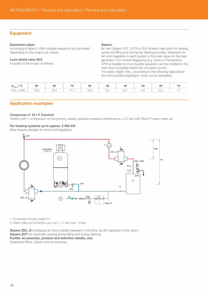
Compresso C 10.1 F ConnectTecBox with 1 compressor on the primary vessel, precision pressure maintenance ± 0,1 bar with Pleno P water make-up
For heating systems up to approx. 2 000 kW(May require changes to meet local legislation)
1. Compresso Primary vessel CU2. Water make-up connection, pw ≥ p0 + 1,7 bar (max. 10 bar)
Zeparo ZIO...S configured as micro bubble separator in the flow, as dirt separator in the return.Zeparo ZUT for automatic venting during filling and during draining.Further accessories, product and selection details, see: Datasheet Pleno, Zeparo and Accessories.
pw
CompressoC 10.1 F
A)
DLV
ZIO...S
Pleno P
tr
Q
psvs
DSV...DGH
m
Hst
ZIO...S
p
ZUT
tmax
1
2
Hst
DNe
13
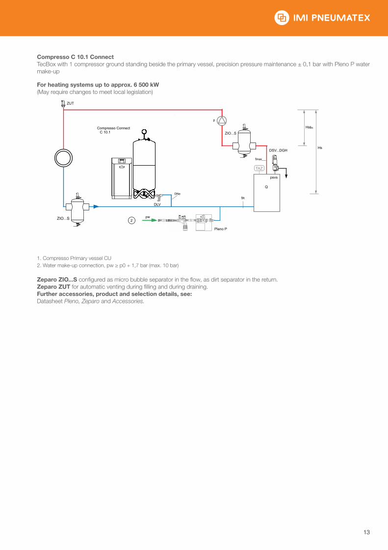
Compresso C 10.1 ConnectTecBox with 1 compressor ground standing beside the primary vessel, precision pressure maintenance ± 0,1 bar with Pleno P water make-up
For heating systems up to approx. 6 500 kW(May require changes to meet local legislation)
1. Compresso Primary vessel CU2. Water make-up connection, pw ≥ p0 + 1,7 bar (max. 10 bar)
Zeparo ZIO...S configured as micro bubble separator in the flow, as dirt separator in the return.Zeparo ZUT for automatic venting during filling and during draining.Further accessories, product and selection details, see: Datasheet Pleno, Zeparo and Accessories.
pw
Compresso ConnectC 10.1
ZIO...S
Pleno P
tR
Q
psvs
DSV...DGH
m
Hst
ZIO...S
p
ZUT
tmax
2
Hst
DNe
DLV
IMI PNEUMATEX / Planning and Calculation / Planning and Calculation
14
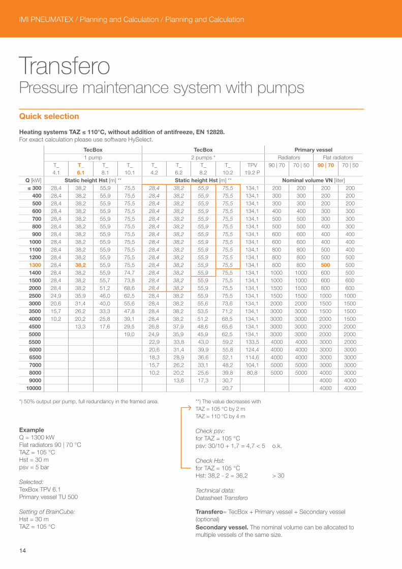
Transfero Pressure maintenance system with pumps
Quick selection
Heating systems TAZ ≤ 110°C, without addition of antifreeze, EN 12828.For exact calculation please use software HySelect.
TecBox TecBox Primary vessel 1 pump 2 pumps * Radiators Flat radiators
T_4.1
T_6.1
T_8.1
T_10.1
T_4.2
T_6.2
T_8.2
T_10.2
TPV19.2 P
90 | 70 70 | 50 90 | 70 70 | 50
Q [kW] Static height Hst [m] ** Static height Hst [m] ** Nominal volume VN [liter] ≤ 300 28,4 38,2 55,9 75,5 28,4 38,2 55,9 75,5 134,1 200 200 200 200
400 28,4 38,2 55,9 75,5 28,4 38,2 55,9 75,5 134,1 300 300 200 200500 28,4 38,2 55,9 75,5 28,4 38,2 55,9 75,5 134,1 300 300 200 200600 28,4 38,2 55,9 75,5 28,4 38,2 55,9 75,5 134,1 400 400 300 300700 28,4 38,2 55,9 75,5 28,4 38,2 55,9 75,5 134,1 500 500 300 300800 28,4 38,2 55,9 75,5 28,4 38,2 55,9 75,5 134,1 500 500 400 300900 28,4 38,2 55,9 75,5 28,4 38,2 55,9 75,5 134,1 600 600 400 400
1000 28,4 38,2 55,9 75,5 28,4 38,2 55,9 75,5 134,1 600 600 400 4001100 28,4 38,2 55,9 75,5 28,4 38,2 55,9 75,5 134,1 800 800 500 4001200 28,4 38,2 55,9 75,5 28,4 38,2 55,9 75,5 134,1 800 800 500 5001300 28,4 38,2 55,9 75,5 28,4 38,2 55,9 75,5 134,1 800 800 500 5001400 28,4 38,2 55,9 74,7 28,4 38,2 55,9 75,5 134,1 1000 1000 600 5001500 28,4 38,2 55,7 73,8 28,4 38,2 55,9 75,5 134,1 1000 1000 600 6002000 28,4 38,2 51,2 68,6 28,4 38,2 55,9 75,5 134,1 1500 1500 800 6002500 24,9 35,9 46,0 62,5 28,4 38,2 55,9 75,5 134,1 1500 1500 1000 10003000 20,6 31,4 40,0 55,6 28,4 38,2 55,6 73,6 134,1 2000 2000 1500 15003500 15,7 26,2 33,3 47,8 28,4 38,2 53,5 71,2 134,1 3000 3000 1500 15004000 10,2 20,2 25,8 39,1 28,4 38,2 51,2 68,5 134,1 3000 3000 2000 15004500 13,3 17,6 29,5 26,8 37,9 48,6 65,6 134,1 3000 3000 2000 20005000 19,0 24,9 35,9 45,9 62,5 134,1 3000 3000 2000 20005500 22,9 33,8 43,0 59,2 133,5 4000 4000 3000 20006000 20,6 31,4 39,9 55,8 124,4 4000 4000 3000 30006500 18,3 28,9 36,6 52,1 114,6 4000 4000 3000 30007000 15,7 26,2 33,1 48,2 104,1 5000 5000 3000 30008000 10,2 20,2 25,6 39,8 80,8 5000 5000 4000 30009000 13,6 17,3 30,7 4000 4000
10000 20,7 4000 4000
*) 50% output per pump, full redundancy in the framed area.
ExampleQ = 1300 kWFlat radiators 90 | 70 °CTAZ = 105 °CHst = 30 mpsv = 5 bar
Selected:TexBox TPV 6.1Primary vessel TU 500
Setting of BrainCube:Hst = 30 mTAZ = 105 °C
**) The value decreases with TAZ = 105 °C by 2 mTAZ = 110 °C by 4 m
Check psv:for TAZ = 105 °Cpsv: 30/10 + 1,7 = 4,7 < 5 o.k.
Check Hst:for TAZ = 105 °CHst: 38,2 - 2 = 36,2 > 30
Technical data:Datasheet Transfero
Transfero= TecBox + Primary vessel + Secondary vessel (optional) Secondary vessel. The nominal volume can be allocated to multiple vessels of the same size.
15
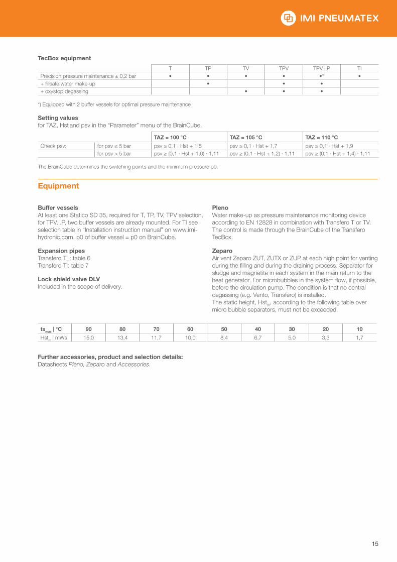
TecBox equipment
T TP TV TPV TPV...P TIPrecision pressure maintenance ± 0,2 bar • • • • •* •+ fillsafe water make-up • • • + oxystop degassing • • •
*) Equipped with 2 buffer vessels for optimal pressure maintenance
Setting valuesfor TAZ, Hst and psv in the “Parameter” menu of the BrainCube.
TAZ = 100 °C TAZ = 105 °C TAZ = 110 °C
Check psv: for psv ≤ 5 bar psv ≥ 0,1 · Hst + 1,5 psv ≥ 0,1 · Hst + 1,7 psv ≥ 0,1 · Hst + 1,9 for psv > 5 bar psv ≥ (0,1 · Hst + 1,0) · 1,11 psv ≥ (0,1 · Hst + 1,2) · 1,11 psv ≥ (0,1 · Hst + 1,4) · 1,11
The BrainCube determines the switching points and the minimum pressure p0.
Equipment
Buffer vesselsAt least one Statico SD 35, required for T, TP, TV, TPV selection, for TPV...P, two buffer vessels are already mounted. For TI see selection table in “Installation instruction manual” on www.imi-hydronic.com. p0 of buffer vessel = p0 on BrainCube.
Expansion pipesTransfero T_: table 6Transfero TI: table 7
Lock shield valve DLVIncluded in the scope of delivery.
PlenoWater make-up as pressure maintenance monitoring device according to EN 12828 in combination with Transfero T or TV. The control is made through the BrainCube of the Transfero TecBox.
ZeparoAir vent Zeparo ZUT, ZUTX or ZUP at each high point for venting during the filling and during the draining process. Separator for sludge and magnetite in each system in the main return to the heat generator. For microbubbles in the system flow, if possible, before the circulation pump. The condition is that no central degassing (e.g. Vento, Transfero) is installed. The static height, Hstm, according to the following table over micro bubble separators, must not be exceeded.
tsmax | °C 90 80 70 60 50 40 30 20 10
Hstm | mWs 15,0 13,4 11,7 10,0 8,4 6,7 5,0 3,3 1,7
Further accessories, product and selection details:Datasheets Pleno, Zeparo and Accessories.
IMI PNEUMATEX / Planning and Calculation / Planning and Calculation
16
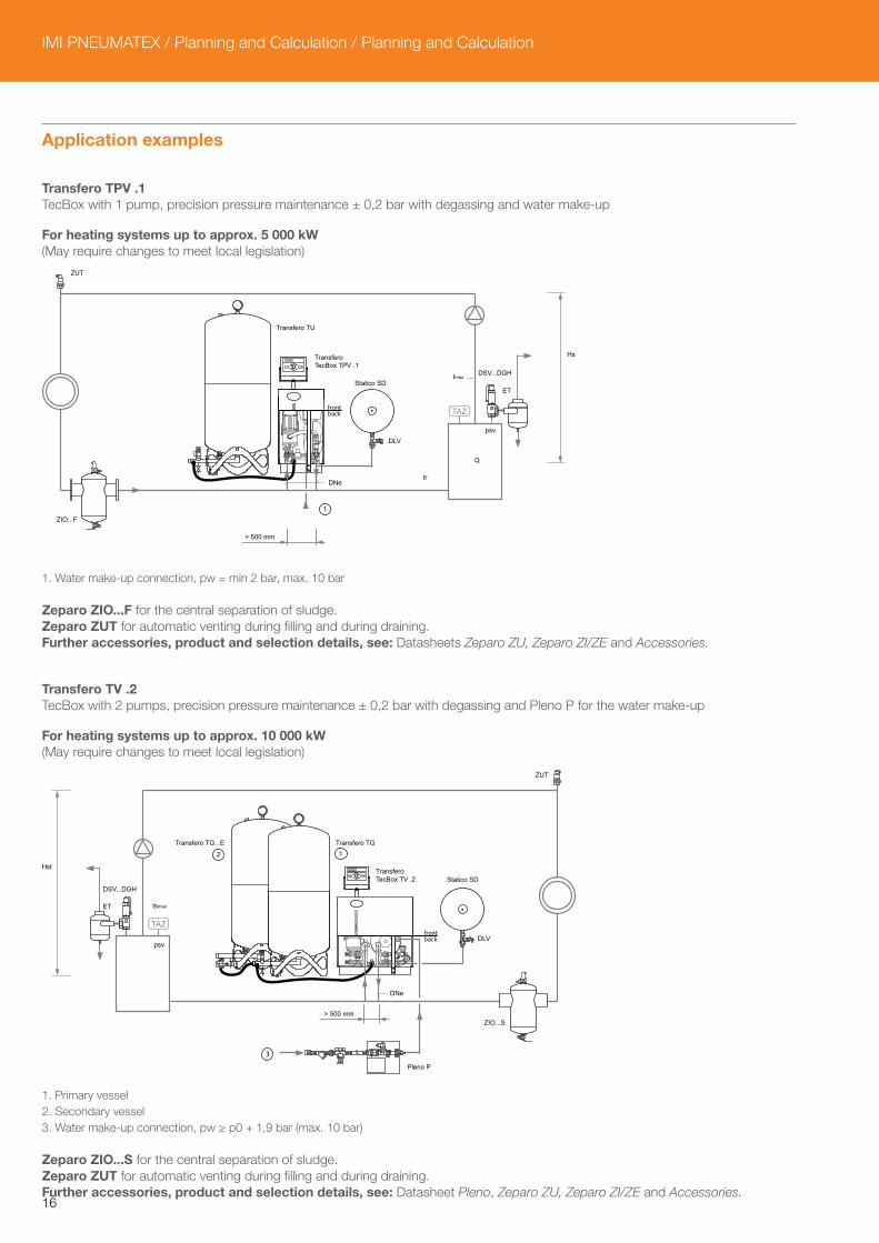
Application examples
Transfero TPV .1 TecBox with 1 pump, precision pressure maintenance ± 0,2 bar with degassing and water make-up
For heating systems up to approx. 5 000 kW(May require changes to meet local legislation)
1. Water make-up connection, pw = min 2 bar, max. 10 bar
Zeparo ZIO...F for the central separation of sludge.Zeparo ZUT for automatic venting during filling and during draining.Further accessories, product and selection details, see: Datasheets Zeparo ZU, Zeparo ZI/ZE and Accessories.
Transfero TV .2 TecBox with 2 pumps, precision pressure maintenance ± 0,2 bar with degassing and Pleno P for the water make-up
For heating systems up to approx. 10 000 kW(May require changes to meet local legislation)
1. Primary vessel2. Secondary vessel3. Water make-up connection, pw ≥ p0 + 1,9 bar (max. 10 bar)
Zeparo ZIO...S for the central separation of sludge.Zeparo ZUT for automatic venting during filling and during draining.Further accessories, product and selection details, see: Datasheet Pleno, Zeparo ZU, Zeparo ZI/ZE and Accessories.
> 500 mm
DNetr
tmaxDSV...DGH
ET
Q
psv
Hst
1
Transfero TU
Transfero TecBox TPV .1
Statico SD
DLV
ZUT
ZIO...F
Transfero TG...E Transfero TG
Transfero TecBox TV .2 Statico SD
DLV
ZIO...S
Hst
DSV...DGH
ET tsmax
psv
Pleno P
> 500 mm
DNe
12
3
ZUT
17
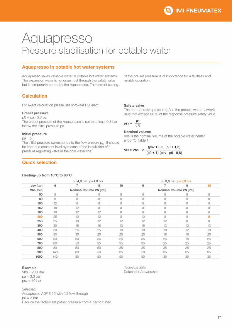
Aquapresso Pressure stabilisation for potable water
Aquapresso in potable hot water systems
Aquapresso saves valuable water in potable hot water systems. The expansion water is no longer lost through the safety valve but is temporarily stored by the Aquapresso. The correct setting
of the pre set pressure is of importance for a faultless and reliable operation.
Calculation
For exact calculation please use software HySelect.
Preset pressurep0 = pa - 0,3 barThe preset pressure of the Aquapresso is set to at least 0,3 bar below the initial pressure pa.
Initial pressurepa = pFL
The initial pressure corresponds to the flow presure pFL. It should be kept at a constant level by means of the installation of a pressure regulating valve in the cold water line.
Safety valveThe non-operative pressure pR in the potable water network must not exceed 80 % of the response pressure safety valve.
Nominal volumeVhs is the nominal volume of the potable water heater.e (60 °C, table 1)
Quick selection
Heating-up from 10°C to 60°C
p0 4,0 bar | pa 4,3 bar p0 3,0 bar | pa 3,3 barpsv [bar] 6 7 8 10 6 7 8 10 Vhs [liter] Nominal volume VN [liter] Nominal volume VN [liter]
50 8 8 8 8 8 8 8 880 8 8 8 8 8 8 8 8
100 12 8 8 8 8 8 8 8150 18 12 8 8 8 8 8 8180 18 12 12 8 8 8 8 8200 25 12 12 8 12 8 8 8250 25 18 12 12 12 12 8 8300 35 18 18 12 18 12 12 12400 50 25 25 18 18 18 12 18500 50 35 25 25 25 18 18 25600 80 50 35 25 35 25 18 25700 80 50 35 35 35 25 25 25800 80 50 50 35 35 35 25 25900 140 80 50 35 50 35 35 35
1000 140 80 50 50 50 35 35 35
ExampleVhs = 200 litrepa = 3,3 barpsv = 10 bar
Selected:Aquapresso ADF 8.10 with full flow-throughp0 = 3 barReduce the factory set preset pressure from 4 bar to 3 bar!
Technical data:Datasheet Aquapresso
psv =pR
0,8
VN = Vhs · e · (psv + 0,5)·(p0 + 1,3)
(p0 + 1)·(psv - p0 - 0,8)
IMI PNEUMATEX / Planning and Calculation / Planning and Calculation
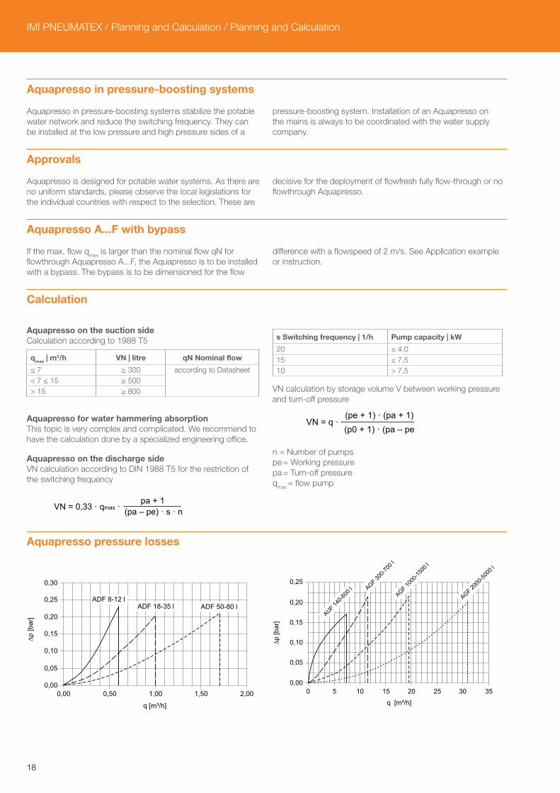
18
Aquapresso in pressure-boosting systems
Aquapresso in pressure-boosting systems stabilize the potable water network and reduce the switching frequency. They can be installed at the low pressure and high pressure sides of a
pressure-boosting system. Installation of an Aquapresso on the mains is always to be coordinated with the water supply company.
Approvals
Aquapresso is designed for potable water systems. As there are no uniform standards, please observe the local legislations for the individual countries with respect to the selection. These are
decisive for the deployment of flowfresh fully flow-through or no flowthrough Aquapresso.
Aquapresso A...F with bypass
If the max. flow qmax is larger than the nominal flow qN for flowthrough Aquapresso A...F, the Aquapresso is to be installed with a bypass. The bypass is to be dimensioned for the flow
difference with a flowspeed of 2 m/s. See Application example or instruction.
Calculation
Aquapresso on the suction sideCalculation according to 1988 T5
qmax | m3/h VN | litre qN Nominal flow
≤ 7 ≥ 300 according to Datasheet< 7 ≤ 15 ≥ 500> 15 ≥ 800
Aquapresso for water hammering absorptionThis topic is very complex and complicated. We recommend to have the calculation done by a specialized engineering office.
Aquapresso on the discharge sideVN calculation according to DIN 1988 T5 for the restriction of the switching frequency
s Switching frequency | 1/h Pump capacity | kW
20 ≤ 4,015 ≤ 7,510 > 7,5
VN calculation by storage volume V between working pressure and turn-off pressure
n = Number of pumpspe = Working pressurepa = Turn-off pressureqmax = flow pump
Aquapresso pressure losses
VN = 0,33 · qmax · pa + 1
(pa – pe) · s · n
VN = q · (pe + 1) · (pa + 1)(p0 + 1) · (pa – pe)
0,00
0,05
0,10
0,15
0,20
0,25
0,30
0,00 0,50 1,00 1,50 2,00
q [m³/h]
∆p [b
ar]
ADF 8-12 lADF 18-35 l ADF 50-80 l
0,00
0,05
0,10
0,15
0,20
0,25
0 5 10 15 20 25 30 35
q [m³/h]
∆p [b
ar]
AUF 140-6
00 l AGF 30
0-700
lAGF 10
00-15
00 l
AGF 2000
-5000
l
19
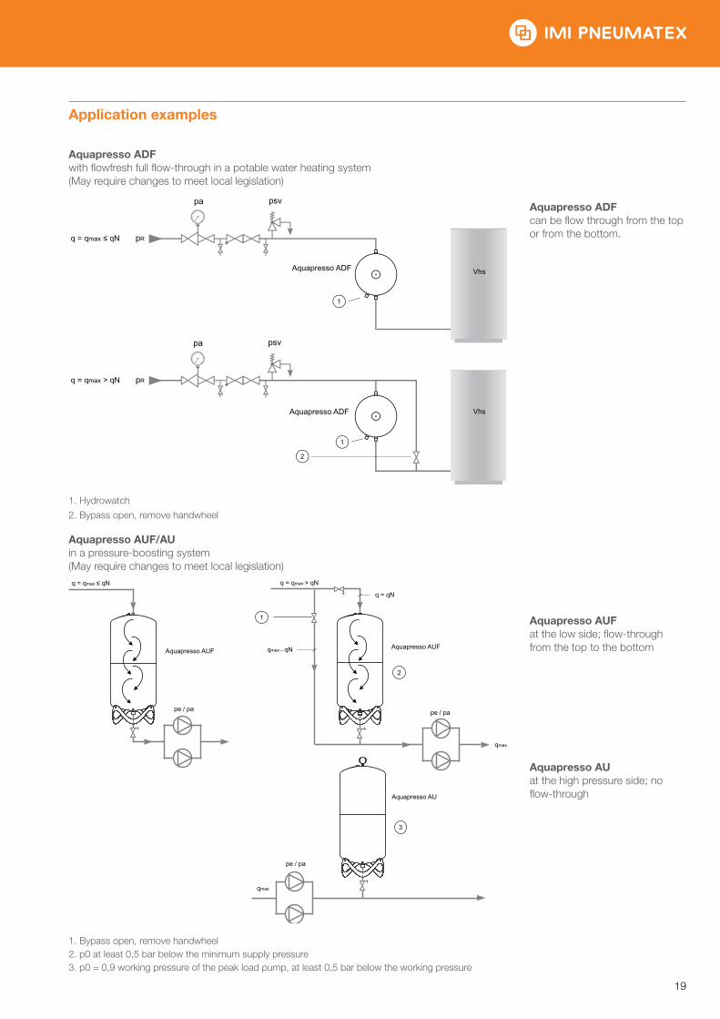
Application examples
Aquapresso ADF with flowfresh full flow-through in a potable water heating system(May require changes to meet local legislation)
Aquapresso ADFcan be flow through from the top or from the bottom.
1. Hydrowatch2. Bypass open, remove handwheel
Aquapresso AUF/AUin a pressure-boosting system(May require changes to meet local legislation)
Aquapresso AUFat the low side; flow-through from the top to the bottom
Aquapresso AUat the high pressure side; no flow-through
1. Bypass open, remove handwheel2. p0 at least 0,5 bar below the minimum supply pressure3. p0 = 0,9 working pressure of the peak load pump, at least 0,5 bar below the working pressure
Aquapresso ADF
Aquapresso ADF
q = qmax ≤ qN
q = qmax > qN pR
pR
2
1
1
Vhs
Vhs
pa psv
pa psv
q = qmax ≤ qN q = qmax > qN
q = qN
qmax – qNAquapresso AUFAquapresso AUF
pe / pa pe / pa
pe / pa
qmax
1
2
3
qmax
Aquapresso AU
IMI PNEUMATEX / Planning and Calculation / Planning and Calculation
20
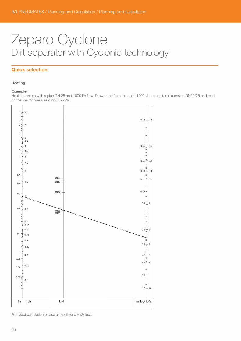
Zeparo Cyclone Dirt separator with Cyclonic technology
Quick selection
Heating
Example:Heating system with a pipe DN 25 and 1000 l/h flow. Draw a line from the point 1000 l/h to required dimension DN20/25 and read on the line for pressure drop 2,5 kPa.
For exact calculation please use software HySelect.
21
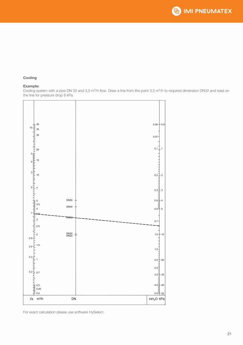
Cooling
Example:Cooling system with a pipe DN 32 and 3,5 m³/h flow. Draw a line from the point 3,5 m³/h to required dimension DN32 and read on the line for pressure drop 8 kPa.
For exact calculation please use software HySelect.
IMI PNEUMATEX / Planning and Calculation / Planning and Calculation
22
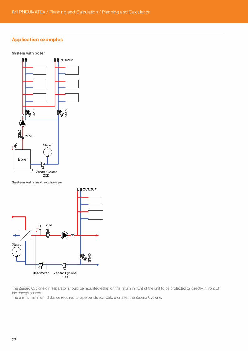
Application examples
System with boiler
System with heat exchanger
The Zeparo Cyclone dirt separator should be mounted either on the return in front of the unit to be protected or directly in front of the energy source.There is no minimum distance required to pipe bends etc. before or after the Zeparo Cyclone.
23
Zeparo Automatic air vents and separators
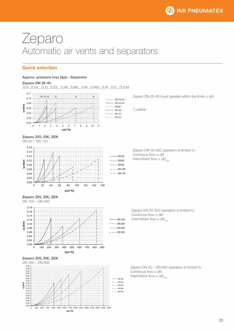
Quick selection
Approx. pressure loss (Δp) – Separator
Zeparo DN 20-40ZUV, ZUVL, ZUD, ZUDL, ZUM, ZUML, ZUK, ZUKM, ZUR, ZUC, ZUCM
Zeparo DN 20-40 must operate within the limits ≤ qN.
*) Lateral
Zeparo ZIO, ZIK, ZEK DN 50 – DN 125
Zeparo DN 50-300 operation is limited to: Continous flow ≤ qNIntermittant flow ≤ qNmax
Zeparo ZIO, ZIK, ZEKDN 150 – DN 300
Zeparo DN 50-300 operation is limited to: Continous flow ≤ qNIntermittant flow ≤ qNmax
Zeparo ZIO, ZIK, ZEKDN 350 – DN 600
Zeparo DN 50 – DN 600 operation is limited to:Continous flow ≤ qNIntermittant flow ≤ qNmax
0,00
0,02
0,04
0,06
0,08
0,10
0 1 2 3 4 5 6 7 8 9 10 11
0,11
DN 20-22 *DN 20-22DN25 *DN 25DN 32DN 40
20-22 25 32 40DN
∆p [b
ar]
q [m3/h]
0,00
0,02
0,04
0,06
0,08
0,10
0,12
0,14
0,16
0 20 40 60 80 100 120 140 160
∆p [b
ar]
q [m3/h]
DN 50
DN 65
DN 80
DN 100
DN 125
0,000,020,040,060,080,100,120,140,160,18
0 100 200 300 400 500 600 700 800 900
DN 150
DN 200
DN 250
DN 300
∆p [b
ar]
q [m3/h]
0,000,020,040,060,080,100,120,140,160,180,200,220,240,260,280,300,32
0 250 500 750 1000 1250 1500 1750 2000 2250 2500 2750 3000 3250 3500
DN 350
DN 400
DN 450
DN 500
DN 600
∆p [b
ar]
q [m3/h]
IMI PNEUMATEX / Planning and Calculation / Planning and Calculation
24
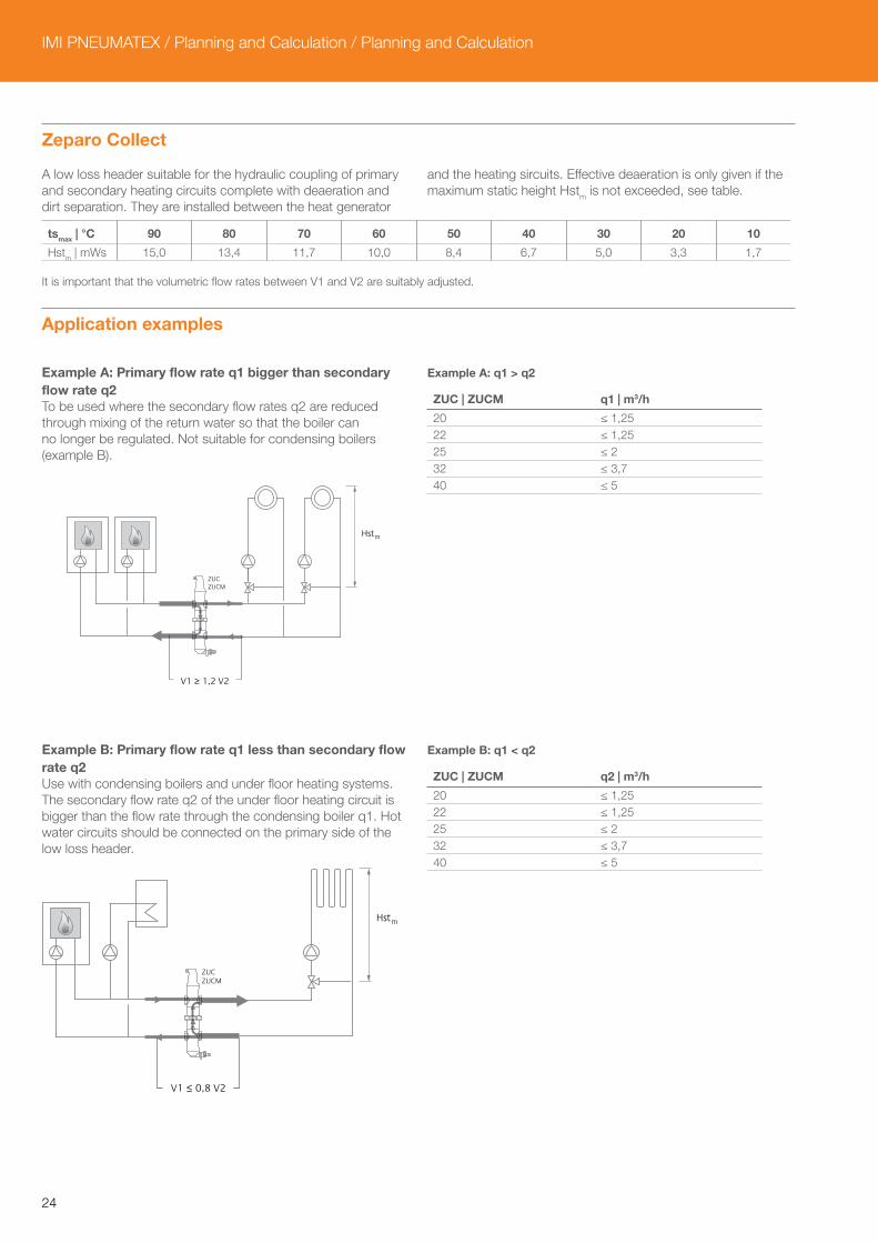
Zeparo Collect
A low loss header suitable for the hydraulic coupling of primary and secondary heating circuits complete with deaeration and dirt separation. They are installed between the heat generator
and the heating sircuits. Effective deaeration is only given if the maximum static height Hstm is not exceeded, see table.
tsmax | °C 90 80 70 60 50 40 30 20 10
Hstm | mWs 15,0 13,4 11,7 10,0 8,4 6,7 5,0 3,3 1,7
It is important that the volumetric flow rates between V1 and V2 are suitably adjusted.
Application examples
Example A: Primary flow rate q1 bigger than secondary flow rate q2To be used where the secondary flow rates q2 are reduced through mixing of the return water so that the boiler can no longer be regulated. Not suitable for condensing boilers (example B).
Example A: q1 > q2
ZUC | ZUCM q1 | m3/h
20 ≤ 1,2522 ≤ 1,2525 ≤ 232 ≤ 3,740 ≤ 5
Example B: Primary flow rate q1 less than secondary flow rate q2Use with condensing boilers and under floor heating systems. The secondary flow rate q2 of the under floor heating circuit is bigger than the flow rate through the condensing boiler q1. Hot water circuits should be connected on the primary side of the low loss header.
Example B: q1 < q2
ZUC | ZUCM q2 | m3/h
20 ≤ 1,2522 ≤ 1,2525 ≤ 232 ≤ 3,740 ≤ 5
ZUC ZUCM
Hst
V1 ≥ 1,2 V2
m
ZUC ZUCM
V1 ≤ 0,8 V2
Hstm

25
Safety technologyDevices for sealed heating systems according to EN 12828 with TAZ ≤ 110°C
Heated directlywith oil, gas, electricity,
solid fuels
Heated indirectlyheat exchanger with
vapour or liquids
Datasheet
General requirements TI Thermometer, display range ≥ 20 % above TAZ • • AccessoriesTAZ Temperature limiter according to EN 60730-2-9 • • 1) AccessoriesTC Temperature controller • • LAZ Low-water protection2) for roof top installations • – AccessoriesPI Manometer, display range ≥ 50 % above PSV • • AccessoriesSV Safety valve, EN 4126 for vapour emission • • 3) AccessoriesPressure maintenance, e.g. Statico, Compresso, Transfero • • Statico, Compresso, TransferoPressure maintenance monitoring device 4), e.g. Pleno • • Pleno Additional requirements for Q > 300 kW / heat generator LAZ Low-water protection 2) • – AccessoriesET Blow tank 5) • • 6) AccessoriesPAZ Pressure limiter • – Additional requirements with slow-action heating Emergency cooling through thermal discharge protection or safety heat consumer, e.g. with solid fuel boilers
• –
1) Temperature controller sufficient according to standard, but not recommended.2) Minimum pressure or flow limiters can be used as an alternative. For central roof units above 300 kW not additionally, 1 low-water protection is sufficient.3) Dimensioning for water discharge with 1 litre/kWh possible if the primary temperature does not exceed the evaporation temperature with the safety valve opening pressure psv.4) Automatic water make-up device (e.g. Pleno) or minimum pressure limiter.5) Substitution with additional TAZ and PAZ possible. EN 12828 does not contain constructive specifications. We recommend to proceed according to the known state of the art of the countries, e.g. SWKI 93-1 in Switzerland or DIN 4751-2 in Germany.6) Only if the vapour pressure pv at flow temperature tprmax is bigger than safety valve opening pressure psv.
Application examples
Safety equipment according to EN 12828(May require changes to meet local legislation)
Directly heated systemQ > 300 kW
1. Pressure maintenance e.g. Statico SU 2. Pressure maintenance monitoring device. Degassing with built-in water make-up, e.g. Vento VP...E3. Water make-up connection
pv (tprmax) > psv
1
23
ET

IMI PNEUMATEX / Planning and Calculation / Planning and Calculation
26
27
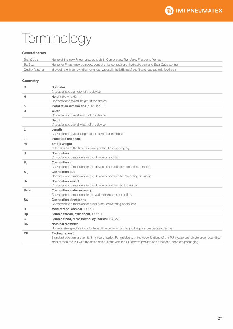
TerminologyGeneral terms
BrainCube Name of the new Pneumatex controls in Compresso, Transfero, Pleno and Vento.
TecBox Name for Pneumatex compact control units consisting of hydraulic part and BrainCube control.
Quality features airproof, silentrun, dynaflex, oxystop, vacusplit, helistill, leakfree, fillsafe, secuguard, flowfresh
Geometry
D DiameterCharacteristic diameter of the device.
H Height (H, H1, H2, …)Characteristic overall height of the device.
h Installation dimensions (h, h1, h2, …)
B WidthCharacteristic overall width of the device.
l DepthCharacteristic overall width of the device
L LengthCharacteristic overall length of the device or the fixture
si Insulation thickness
m Empty weightof the device at the time of delivery without the packaging.
S ConnectionCharacteristic dimension for the device connection.
Sin Connection inCharacteristic dimension for the device connection for streaming in media.
Sout Connection outCharacteristic dimension for the device connection for streaming off media.
Sv Connection vesselCharacteristic dimension for the device connection to the vessel.
Swm Connection water make-upCharacteristic dimension for the water make-up connection.
Sw Connection dewateringCharacteristic dimension for evacuation, dewatering operations.
R Male thread, conical, ISO 7-1
Rp Female thread, cylindrical, ISO 7-1
G Female tread, male thread, cylindrical, ISO 228
DN Nominal diameterNumeric size specifications for tube dimensions according to the pressure device directive.
PU Packaging unitStandard packaging quantity in a box or pallet. For articles with the specifications of the PU please coordinate order quantities smaller than the PU with the sales office. Items within a PU always provide of a functional separate packaging.
IMI PNEUMATEX / Planning and Calculation / Terminology
28
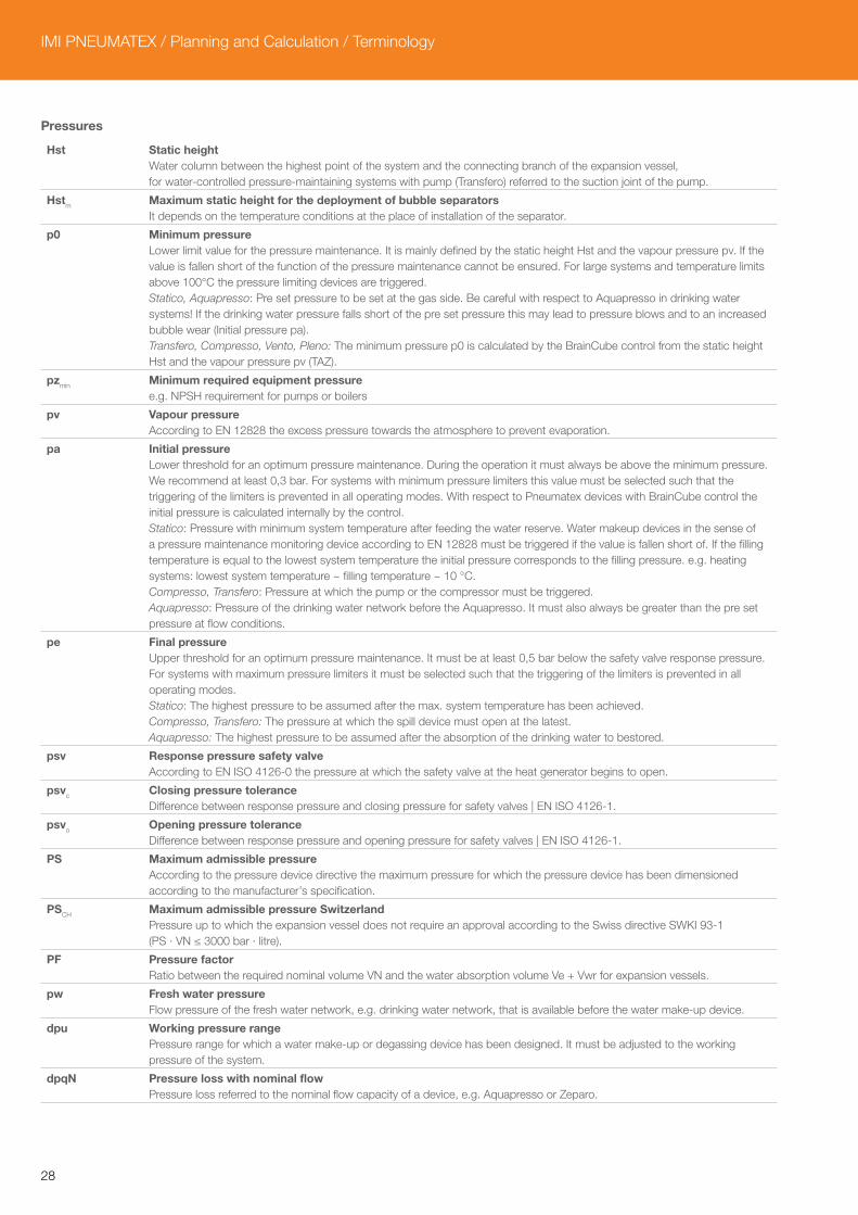
Pressures
Hst Static heightWater column between the highest point of the system and the connecting branch of the expansion vessel, for water-controlled pressure-maintaining systems with pump (Transfero) referred to the suction joint of the pump.
Hstm Maximum static height for the deployment of bubble separatorsIt depends on the temperature conditions at the place of installation of the separator.
p0 Minimum pressureLower limit value for the pressure maintenance. It is mainly defined by the static height Hst and the vapour pressure pv. If the value is fallen short of the function of the pressure maintenance cannot be ensured. For large systems and temperature limits above 100°C the pressure limiting devices are triggered.Statico, Aquapresso: Pre set pressure to be set at the gas side. Be careful with respect to Aquapresso in drinking water systems! If the drinking water pressure falls short of the pre set pressure this may lead to pressure blows and to an increased bubble wear (Initial pressure pa).Transfero, Compresso, Vento, Pleno: The minimum pressure p0 is calculated by the BrainCube control from the static height Hst and the vapour pressure pv (TAZ).
pzmin Minimum required equipment pressuree.g. NPSH requirement for pumps or boilers
pv Vapour pressureAccording to EN 12828 the excess pressure towards the atmosphere to prevent evaporation.
pa Initial pressureLower threshold for an optimum pressure maintenance. During the operation it must always be above the minimum pressure. We recommend at least 0,3 bar. For systems with minimum pressure limiters this value must be selected such that the triggering of the limiters is prevented in all operating modes. With respect to Pneumatex devices with BrainCube control the initial pressure is calculated internally by the control.Statico: Pressure with minimum system temperature after feeding the water reserve. Water makeup devices in the sense of a pressure maintenance monitoring device according to EN 12828 must be triggered if the value is fallen short of. If the filling temperature is equal to the lowest system temperature the initial pressure corresponds to the filling pressure. e.g. heating systems: lowest system temperature ~ filling temperature ~ 10 °C.Compresso, Transfero: Pressure at which the pump or the compressor must be triggered.Aquapresso: Pressure of the drinking water network before the Aquapresso. It must also always be greater than the pre set pressure at flow conditions.
pe Final pressureUpper threshold for an optimum pressure maintenance. It must be at least 0,5 bar below the safety valve response pressure. For systems with maximum pressure limiters it must be selected such that the triggering of the limiters is prevented in all operating modes.Statico: The highest pressure to be assumed after the max. system temperature has been achieved.Compresso, Transfero: The pressure at which the spill device must open at the latest.Aquapresso: The highest pressure to be assumed after the absorption of the drinking water to bestored.
psv Response pressure safety valveAccording to EN ISO 4126-0 the pressure at which the safety valve at the heat generator begins to open.
psvc Closing pressure toleranceDifference between response pressure and closing pressure for safety valves | EN ISO 4126-1.
psvo Opening pressure toleranceDifference between response pressure and opening pressure for safety valves | EN ISO 4126-1.
PS Maximum admissible pressureAccording to the pressure device directive the maximum pressure for which the pressure device has been dimensioned according to the manufacturer’s specification.
PSCH Maximum admissible pressure SwitzerlandPressure up to which the expansion vessel does not require an approval according to the Swiss directive SWKI 93-1 (PS · VN ≤ 3000 bar · litre).
PF Pressure factorRatio between the required nominal volume VN and the water absorption volume Ve + Vwr for expansion vessels.
pw Fresh water pressureFlow pressure of the fresh water network, e.g. drinking water network, that is available before the water make-up device.
dpu Working pressure rangePressure range for which a water make-up or degassing device has been designed. It must be adjusted to the working pressure of the system.
dpqN Pressure loss with nominal flowPressure loss referred to the nominal flow capacity of a device, e.g. Aquapresso or Zeparo.

29
Volumes
e Expansion coefficientAccording to EN 12828 the factor for the calculation of the expansion volume from the water capacity. In this case, referred to the solidification point.
Vs Overall system water capacityAccording to EN 12828 the overall water capacity of the heating system that is involved in the volume expansion.
vs Specific overall system water capacityOverall water capacity of the heating system that is involved in the volume expansion, referred to the installed heating surface output.
VN Nominal volumeAccording to the pressure device directive the entire internal volume of the pressure compartment of the expansion vessel.
VNd Water capacity for which a device is ratedCharacteristic performance parameter that describes up to which water capacity the device, e.g. Vento, can be used.
Vg Water content collector panelsFor solar systems to ENV 12977-1 the collector volume which can phase change to steam has to be added to the connecting pipes volume.
Ve Expansion volumeAccording to EN 12828 the volume expansion of the water capacity of the heating system between the min. and max. system temperature.
Vwr Water reserveAccording to EN 12828 the water quantity in the expansion vessel for the compensation of water losses caused by the system.
Temperatures
tsmax Maximum system temperatureMaximum temperature for the calculation of the volume expansion. For heating systems the dimensioned flow temperature at which a heating system is to be operated with the lowest outside temperature to be assumed (standard outside temperature according to EN 12828). For cooling systems the max. temperature that is achieved due to the operation mode or standstill, for solar systems the temperature up to which an evaporation is to be avoided.
tsmin Lowest system temperatureLowest temperature for calculating expansion volumes. The lowest system temperature is equal to the freezing point. It is dependant on the percentage of antifreeze additives. For water without additives tsmin = 0.
tpr Primary flow temperatureMaximum flow temperature in primary circuit of heat exchangers (indirect fired).
tr Return temperatureReturn temperature of the heating system with the lowest outside temperature to be assumed (standard outside temperature according to EN 12828).
TV Maximum flow temperatureMaximum flow temperature for which a device is equipped according to the normative and safetyrelated requirements. TV may be greater than TS if the device is installed at a place with t ≤ TS, e.g. in the system return.
TAZ Safety temperature limiter | Safety temperature controller | Temperature limitSafety device according to EN 12828 for the temperature protection of heat generators. If the set temperature limit is exceeded the heating is turned off. Limiters are locked, controllers automatically release the heat supply if the set temperature is fallen short of. Setting value for systems according to EN 12828 ≤ 110 °C.
TS Maximum admissible temperatureAccording to the pressure device directive the maximum temperature for which the pressure device or the fixture has been dimensioned according to the manufacturer’s specification.
TSmin Minimum admissible temperatureAccording to the pressure device directive the minimum temperature for which the pressure device or the fixture has been dimensioned according to the manufacturer’s specification.
TWM Maximum admissible temperature for water make upThe highest admissible temperature for make up units as part of a pressurisation or degassing system.This only applies if TWM < TS.
TB Maximum admissible bag temperatureMaximum admissible permanent temperature for the butyl bag.
TBmin Minimum admissible bag temperatureMinimum admissible permanent temperature for the butyl bag.
TA Maximum admissible ambient temperatureMaximum ambient temperature for the installation of a device.
IMI PNEUMATEX / Planning and Calculation / Terminology
30
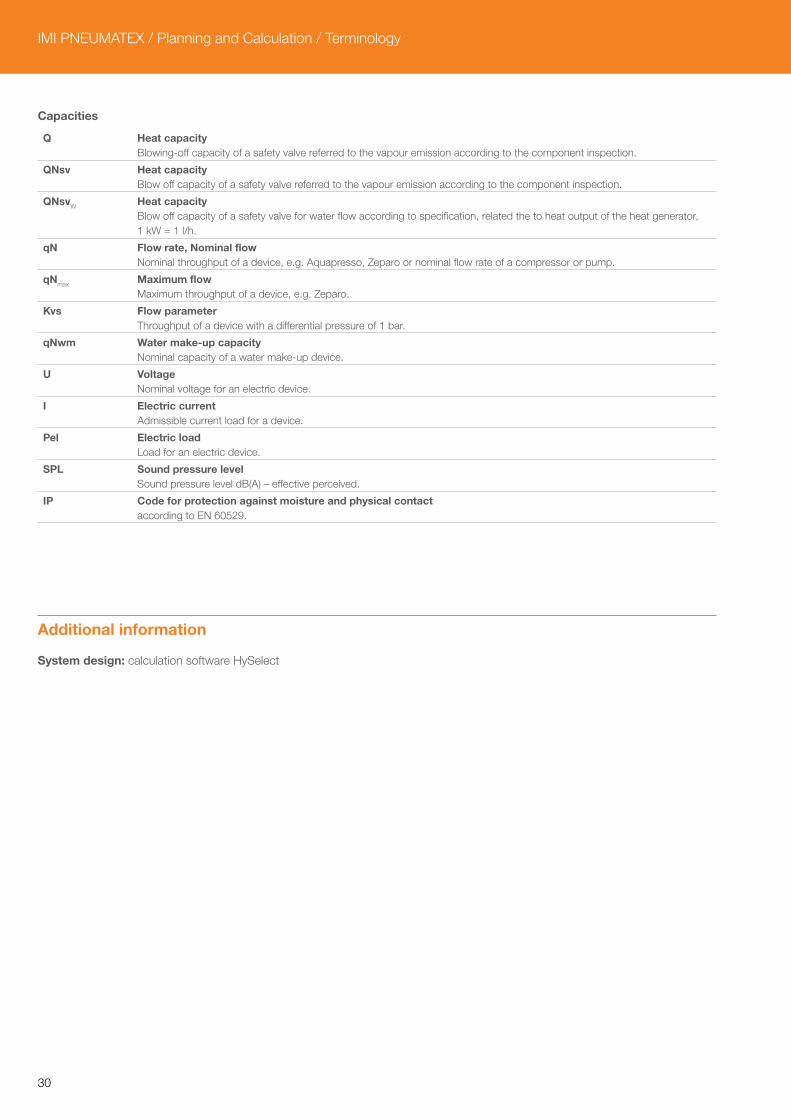
Capacities
Q Heat capacityBlowing-off capacity of a safety valve referred to the vapour emission according to the component inspection.
QNsv Heat capacityBlow off capacity of a safety valve referred to the vapour emission according to the component inspection.
QNsvW Heat capacityBlow off capacity of a safety valve for water flow according to specification, related the to heat output of the heat generator, 1 kW = 1 l/h.
qN Flow rate, Nominal flowNominal throughput of a device, e.g. Aquapresso, Zeparo or nominal flow rate of a compressor or pump.
qNmax Maximum flowMaximum throughput of a device, e.g. Zeparo.
Kvs Flow parameterThroughput of a device with a differential pressure of 1 bar.
qNwm Water make-up capacityNominal capacity of a water make-up device.
U VoltageNominal voltage for an electric device.
I Electric currentAdmissible current load for a device.
Pel Electric loadLoad for an electric device.
SPL Sound pressure levelSound pressure level dB(A) – effective perceived.
IP Code for protection against moisture and physical contactaccording to EN 60529.
Additional information
System design: calculation software HySelect

31

IMI PNEUMATEX / Planning and Calculation / Terminology
The products, texts, photographs, graphics and diagrams in this document may be subject to alteration by IMI Hydronic Engineering without prior notice or reasons being given. For the most up
to date information about our products and specifications, please visit www.imi-hydronic.com.
EN Planning and Calculation 02.2015