PLANNING, ANALYSIS AND DESIGN OF SELF … · planning, analysis and design of self sustainable foot...
7
PLANNING, ANALYSIS AND DESIGN OF SELF SUSTAINABLE FOOT OVER BRIDGE WITH WIND TURBINE AND COMPARATIVE STUDY OF COMPOSITE AND STEEL MATERIAL RAMASUBRAMANI R *, SRIDHAR B, ARUNKUMAR G AND RANJIT RAVI BOSCO Department of Civil Engineering, Faculty of Engineering and Technology, SRM University, Kattankulathur-603 203, Tamil Nadu, India (Received 17 June, 2017; accepted 22 August, 2017) Key words: Over bridge, Pedestrian, Constraints, Reinforcement Jr. of Industrial Pollution Control 33(S2)(2017) pp 1274-1280 www.icontrolpollution.com Research Article *Corresponding authors email: [email protected]; [email protected]; arunkmr.131@ gmail.com; [email protected] INTRODUCTION To analysis the structural elements of a foot over bridge (beam column, staircase, truss, purlin, rafter, reinforced cement concrete deck slab, and reinforced cement concrete foundation and wind turbine). To design the structural elements of a foot over bridge. To do analogize study of analysis, the design of steel and composite self-sustainable foot over bridge with the wind turbine (Ayyadurai, et al., 2013; Mashyal and Anil, 2014). NECESSITY The government of India enacted the energy conservation act 2001. This law provides an institutional arrangement and a regulatory mechanism at the central and state level to begin a drive to promote energy efficiency in the country. The ministry of new and renewable energy (MNRE) has initiated certain comprehensive programs for the development and utilization of renewables. So this becomes the necessity to have a structure which can utilize the naturally available energy. SCOPE Structural elements (beam, column, staircase, truss, purlin, rafter, Reinforced Cement Concrete deck slab, and Reinforced Cement Concrete foundation and wind turbine) are designed. The Structure is designed for shear and dynamic load. Comparisons of the shear are found by using STAAD. Pro (Sharma, 2012; Hassan and Vittala, 2014; Malave and Bhosale, 2013). ABSTRACT With the rapid development of national economy in Chennai, imbalance between supply and demand of traffic infrastructures becomes more and more acute, traffic block becomes even more serious, and one of causes is confliction of pedestrian and motor vehicle. Nowadays, pedestrian bridge is an important measure of resolving traffic problems to form people-oriented walk traffic system in Chennai. Building pedestrian bridge is to separate pedestrian from motor vehicle in space, resolve traffic congestion of main road, closely connect pedestrian bridge with subway, sidewalk, shopping promenade, urban residential area and square to perfect walk traffic system and improve trip environment. Certainly, multilevel, multifunctional and multi-implied public space is created besides traffic function of pedestrian bridge, but its traffic function is the primary function now a days. The city pedestrian bridge will only work if it is rationally construction. Among the many factors contributing to the success of the pedestrian bridge construction, the more important one is general layout. To overcome economic constraints, economical design methods are adopted using economically efficient products. To overcome Sustainability constraints, these constraints high performance concrete is used for the construction if applicable. Manufacturability constraints: This can include redesigning of product to reduce the number of parts, simplify fabrication, or utilize common parts and materials.
Transcript of PLANNING, ANALYSIS AND DESIGN OF SELF … · planning, analysis and design of self sustainable foot...

PLANNING, ANALYSIS AND DESIGN OF SELF SUSTAINABLE FOOT OVER BRIDGE WITH WIND TURBINE AND COMPARATIVE STUDY OF
COMPOSITE AND STEEL MATERIALRAMASUBRAMANI R *, SRIDHAR B, ARUNKUMAR G AND RANJIT RAVI BOSCO
Department of Civil Engineering, Faculty of Engineering and Technology, SRM University, Kattankulathur-603 203, Tamil Nadu, India
(Received 17 June, 2017; accepted 22 August, 2017)
Key words: Over bridge, Pedestrian, Constraints, Reinforcement
Jr. of Industrial Pollution Control 33(S2)(2017) pp 1274-1280www.icontrolpollution.comResearch Article
*Corresponding authors email: [email protected]; [email protected]; [email protected]; [email protected]
INTRODUCTION To analysis the structural elements of a foot over
bridge (beam column, staircase, truss, purlin, rafter, reinforced cement concrete deck slab, and reinforced cement concrete foundation and wind turbine). To design the structural elements of a foot over bridge. To do analogize study of analysis, the design of steel and composite self-sustainable foot over bridge with the wind turbine (Ayyadurai, et al., 2013; Mashyal and Anil, 2014).
NECESSITYThe government of India enacted the
energy conservation act 2001. This law provides an institutional arrangement and a regulatory mechanism at the central and state level to begin a
drive to promote energy efficiency in the country. The ministry of new and renewable energy (MNRE) has initiated certain comprehensive programs for the development and utilization of renewables. So this becomes the necessity to have a structure which can utilize the naturally available energy.
SCOPEStructural elements (beam, column, staircase,
truss, purlin, rafter, Reinforced Cement Concrete deck slab, and Reinforced Cement Concrete foundation and wind turbine) are designed. The Structure is designed for shear and dynamic load. Comparisons of the shear are found by using STAAD. Pro (Sharma, 2012; Hassan and Vittala, 2014; Malave and Bhosale, 2013).
ABSTRACT
With the rapid development of national economy in Chennai, imbalance between supply and demand of traffic infrastructures becomes more and more acute, traffic block becomes even more serious, and one of causes is confliction of pedestrian and motor vehicle. Nowadays, pedestrian bridge is an important measure of resolving traffic problems to form people-oriented walk traffic system in Chennai. Building pedestrian bridge is to separate pedestrian from motor vehicle in space, resolve traffic congestion of main road, closely connect pedestrian bridge with subway, sidewalk, shopping promenade, urban residential area and square to perfect walk traffic system and improve trip environment. Certainly, multilevel, multifunctional and multi-implied public space is created besides traffic function of pedestrian bridge, but its traffic function is the primary function now a days. The city pedestrian bridge will only work if it is rationally construction. Among the many factors contributing to the success of the pedestrian bridge construction, the more important one is general layout. To overcome economic constraints, economical design methods are adopted using economically efficient products. To overcome Sustainability constraints, these constraints high performance concrete is used for the construction if applicable. Manufacturability constraints: This can include redesigning of product to reduce the number of parts, simplify fabrication, or utilize common parts and materials.
1275 NAIK ET AL.
MAJOR DESIGN EXPERIENCE• Design of steel beam
• Design of steel column
• Design of staircase
• Design of truss (purlin, rafter)
• Design of reinforced cement concrete deck slab
• Model of the reinforced cement concrete foundation
• Design for the shear
• Design for dynamic load carrying capacity
• Appropriate location of the wind turbine (trial and error method).
REALISTIC DESIGN CONSTRAINTSEconomic constraints
The initial costs involved in design and construction of the structural components of the bridge such as planning, design etc. can be included in the initial cost, but the cost may arise as a result of exceedance of various critical failure limit states that may occur in the lifespan of a steel bridge. To overcome economic constraints, economical design methods are adopted using economically efficient products.
Sustainability constraints
The process of developing engineering devices, products, and systems that use the resources available to it to meet the own needs of the present without compromising the ability of future generations to also meet their own needs. To overcome these constraints high performance concrete is used for the construction if applicable.
Manufacturability constraints
This can include redesigning of product to reduce the number of parts, simplify fabrication, or utilize common parts and materials (Maurya, et al., 2015; Banerjee and Prozzi, 2012).
PLANNINGOnce the survey is done planning of a structure
is done in a detailing way some of the drawings are shown below:
1. Here the top view and side view of the structure is given under approximate dimensions similar to dimensions of done case studies.
2. All the dimensions have been considered
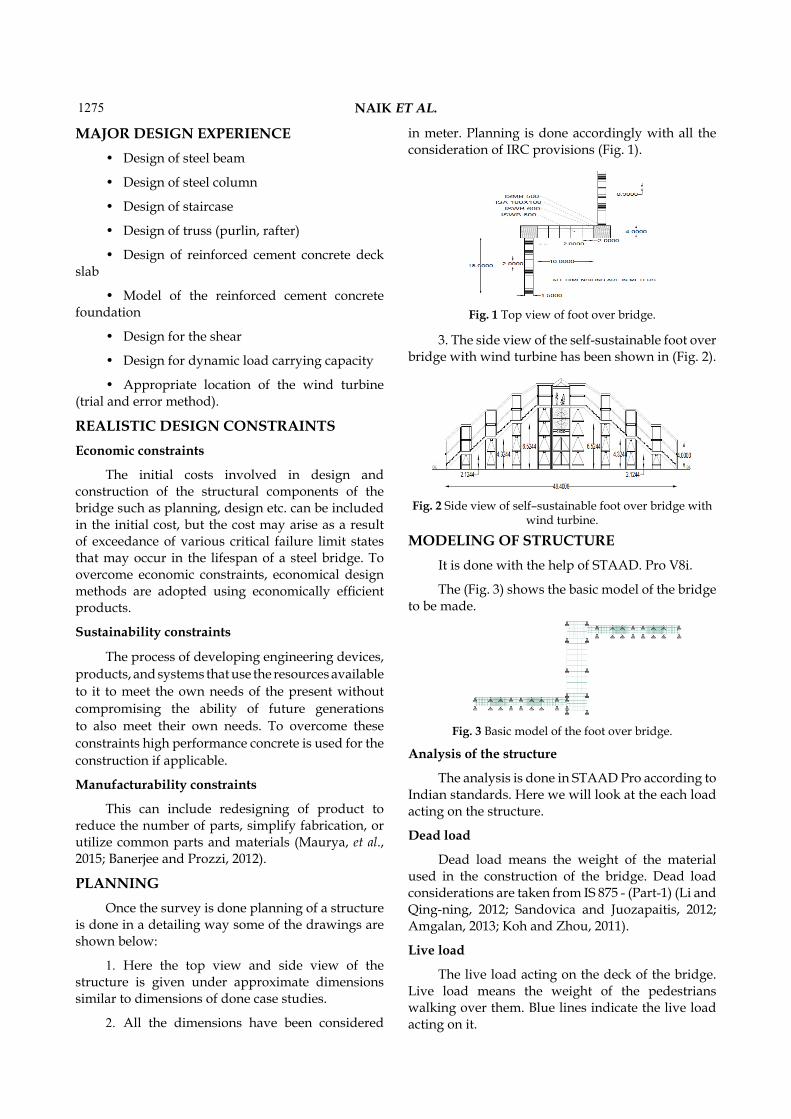
in meter. Planning is done accordingly with all the consideration of IRC provisions (Fig. 1).
Fig. 1 Top view of foot over bridge.
3. The side view of the self-sustainable foot over bridge with wind turbine has been shown in (Fig. 2).
Fig. 2 Side view of self–sustainable foot over bridge with wind turbine.
MODELING OF STRUCTUREIt is done with the help of STAAD. Pro V8i.
The (Fig. 3) shows the basic model of the bridge to be made.
Fig. 3 Basic model of the foot over bridge.
Analysis of the structure
The analysis is done in STAAD Pro according to Indian standards. Here we will look at the each load acting on the structure.
Dead load
Dead load means the weight of the material used in the construction of the bridge. Dead load considerations are taken from IS 875 - (Part-1) (Li and Qing-ning, 2012; Sandovica and Juozapaitis, 2012; Amgalan, 2013; Koh and Zhou, 2011).
Live load
The live load acting on the deck of the bridge. Live load means the weight of the pedestrians walking over them. Blue lines indicate the live load acting on it.
1276STABILIZATION OF TALL BUILDING AGAINST THE WIND LOAD
The live load considerations are taken from the provisions with all the considerations from IS 875 – (Part-2)
Wind load
Since this is an open structure with a wind turbine. The wind load is taken into consideration.
Wind load is considered according to Indian standards of code IS 875(Part-3).
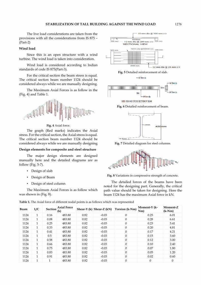
For the critical section the beam stress is equal. The critical section beam number 1124 should be considered always while we are manually designing.
The Maximum Axial Forces is as follow in the (Fig. 4) and Table 1.
Fig. 4 Axial force.
The graph (Red marks) indicates the Axial stress. For the critical section, the Axial stress is equal. The critical section beam number 1124 should be considered always while we are manually designing
Design elements for composite and steel structure
The major design elements are designed manually here and the detailed diagrams are as follow (Fig. 5-7).
• Design of slab
• Design of Beam
• Design of steel column
The Maximum Axial Forces is as follow which was shown in (Fig. 8).
Fig. 5 Detailed reinforcement of slab.
Fig. 6 Detailed reinforcement of beam.
Fig. 7 Detailed diagram for steel columns.
Fig. 8 Variations in compressive strength of concrete.
The detailed forces of the beams have been noted for the designing part. Generally, the critical path value should be taken for designing. Here the beam 1124 has the maximum Axial force in kN.
Beam L/C Section Axial Force (k) Shear-Y (k) Shear-Z (kN) Torsion (k-Nm) Moment-Y (k-
Nm)Moment-Z (k-Nm)
1124 1 0.16 483.80 0.82 -0.03 0 0.25 6.011124 1 0.08 483.80 0.82 -0.03 0 0.28 6.611124 1 0.25 483.80 0.82 -0.03 0 0.23 5.411124 1 0.33 483.80 0.82 -0.03 0 0.20 4.811124 1 0.41 483.80 0.82 -0.03 0 0.17 4.211124 1 0.5 483.80 0.82 -0.03 0 0.15 3.601124 1 0.58 483.80 0.82 -0.03 0 0.12 3.001124 1 0.66 483.80 0.82 -0.03 0 0.10 2.401124 1 0.75 483.80 0.82 -0.03 0 0.07 1.801124 1 0.83 483.80 0.82 -0.03 0 0.05 1.201124 1 0.91 483.80 0.82 -0.03 0 0.02 0.601124 1 1 483.80 0.82 -0.03 0 0 0
Table 1. The Axial force of different nodal points is as follows which was represented

1277 NAIK ET AL.
The values of axial force of different section and it as follows Table 2 and (Fig. 9-12).
Fig. 9 Detailed diagram for steel beam.
Fig. 10 Detailed diagram of stair case.
Fig. 11 Detailed diagram of gusset plate.
Fig. 12 Gusset plate thickness.
• Design of steel beam
• Design of stair case
• Design of gusset plate
COMPARISION OF BOTH STRUCTURESSince wind turbine plays a key role in the
structure first we will see the installions and advantages of turbine.
Installations
The wind turbine installation will be taken place according to type of axis i.e., either horizontal axis or vertical axis.
Turbine
There are two types of turbines in general, one among that is a vertical axis wind turbine, and this is taken into consideration because of economic and low maintenance.
VAWT is the most popular of the turbines that people are adding to make their home a source of renewable energy. Vertical Axis Wind Turbines are designed to be economical and practical, as well as quiet and efficient. They are great for use in residential areas.
Advantages
• Since VAWT are mounted closer to the ground they make maintenance easier, reduce the construction costs, are more bird friendly and does not destroy the wildlife.
• You do not need any mechanisms in order to operate the wind turbine
• Lower wind start-up speed
• The main advantage of VAWT is it does not
Beam L/C Section Axial Force (k)
Shear-Y (k) Shear-Z (k-N) Torsion (k-Nm) Moment-Y (k-
Nm)Moment-Z (k-
Nm)1124 1 1 181.1 0.03 -0.01 0 0 01125 1 1 181.0 -0.03 -0.01 0 0 01124 1 0.91 180.2 0.03 -0.01 0 0 0.021125 1 0.91 180.1 -0.03 -0.01 0 0 -0.021124 1 0.83 179.2 0.03 -0.01 0 0.01 0.041125 1 0.83 179.2 -0.03 -0.01 0 0.01 -0.041124 1 0.75 178.3 0.03 -0.01 0 0.02 0.061125 1 0.75 178.2 -0.03 -0.01 0 0.02 -0.061124 1 0.66 177.4 0.03 -0.01 0 0.02 0.081125 1 0.66 177.3 -0.03 -0.01 0 0.03 -0.081124 1 0.58 176.4 0.03 -0.01 0 0.03 0.111125 1 0.58 176.4 -0.03 -0.01 0 0.04 -0.111124 1 0.5 175.5 0.03 -0.01 0 0.04 0.131125 1 0.5 175.5 -0.03 -0.01 0 0.04 -0.13
Table 2. Axial force tabular column is here

1278STABILIZATION OF TALL BUILDING AGAINST THE WIND LOAD
need to be pointed towards the wind to be effective. In other words, they can be used on the sites with high variable wind direction.
• You can use the wind turbine where tall structures are not allowed.
• VAWT’s are quiet, efficient, economical and perfect for residential energy production, especially in urban environments.
• Valuable protection and extra durability.
Piezoelectric materials and solar panels
• In this project, we are generating electrical power as a non-conventional method by simply walking or running on the foot step.
• Converting mechanical energy to electrical energy.
• It uses the piezoelectric sensor.
• Solar panel refers to a panel designed to absorb the sun's rays as a source of energy for generating electricity or heating.
Piezoelectric Sensor
A piezoelectric sensor is a device that uses the piezoelectric effect to measure pressure, acceleration, strain or force by converting them to an electrical signal.
Applications
• Footstep generated power can be used for various purpose like street lights etc.
• It can be used in emergency power failure situations.
Advantages
• Reliable, Economical, Eco-Friendly
• Less consumption of non-renewable energies, free of noise and no vibration.
• Self-generating – no external power required.
Comparison of both structures
Here, the deflection and bending shear for the critical beam.
From the STAAD Pro analysis, beam number 5 has maximum deflection (Fig. 13) and Table 3.
The maximum deflection for steel shown below in (Fig. 14) and Table 4.
Here, the deflection for steel is less when compared with composite structure. So, by terms of deflection we can clearly say steel is preferred (IS:
808- 1989; IS: 80-2007; IS 456- 2000; IRC 006; IRC SP 075; IRC 084).
Fig. 13 Deflection result for composite critical beam.
Table 3. The various deflections for different spans of the critical beam is as follows
Distance (m) Displacement(mm)0 0
0.72666669 0.0551.45333338 0.1082.18000007 0.1572.90666676 0.2023.63333344 0.244.36000013 0.2695.08666682 0.2885.81333351 0.2966.5400002 0.2897.26666689 0.2687.99333358 0.2298.72000027 0.172
Fig. 14 Deflection result for steel critical beam.
Table 4. The deflection values of beam 5 at different spans are shown
Distance (m) Displacement (mm)0 0
0.72666669 0.0221.45333338 0.0422.18000007 0.0622.90666676 0.083.63333344 0.0964.36000013 0.1095.08666682 0.1185.81333351 0.1236.5400002 0.1247.26666689 0.1197.99333358 0.1088.72000027 0.091
The maximum bending and shear for steel have shown below. Considering shear since wind turbine is placed below the deck slab the vibrations will be high but we can restrict by using Vertical axis turbine.
1279STABILIZATION OF TALL BUILDING AGAINST THE WIND LOAD
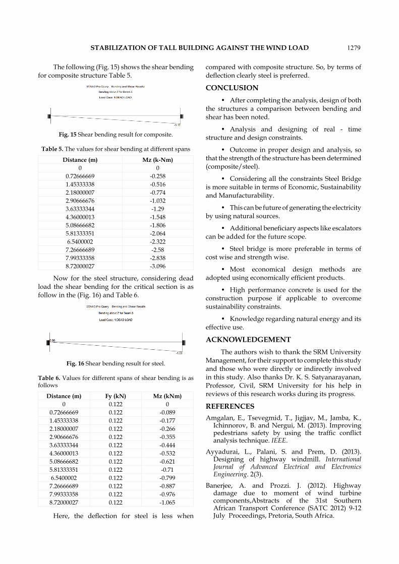
The following (Fig. 15) shows the shear bending for composite structure Table 5.
Fig. 15 Shear bending result for composite.
Table 5. The values for shear bending at different spans
Distance (m) Mz (k-Nm)0 0
0.72666669 -0.2581.45333338 -0.5162.18000007 -0.7742.90666676 -1.0323.63333344 -1.294.36000013 -1.5485.08666682 -1.8065.81333351 -2.0646.5400002 -2.3227.26666689 -2.587.99333358 -2.8388.72000027 -3.096
Now for the steel structure, considering dead load the shear bending for the critical section is as follow in the (Fig. 16) and Table 6.
Fig. 16 Shear bending result for steel.
Table 6. Values for different spans of shear bending is as follows
Distance (m) Fy (kN) Mz (kNm)0 0.122 0
0.72666669 0.122 -0.0891.45333338 0.122 -0.1772.18000007 0.122 -0.2662.90666676 0.122 -0.3553.63333344 0.122 -0.4444.36000013 0.122 -0.5325.08666682 0.122 -0.6215.81333351 0.122 -0.716.5400002 0.122 -0.799
7.26666689 0.122 -0.8877.99333358 0.122 -0.9768.72000027 0.122 -1.065
Here, the deflection for steel is less when
compared with composite structure. So, by terms of deflection clearly steel is preferred.
CONCLUSION• After completing the analysis, design of both
the structures a comparison between bending and shear has been noted.
• Analysis and designing of real - time structure and design constraints.
• Outcome in proper design and analysis, so that the strength of the structure has been determined (composite/steel).
• Considering all the constraints Steel Bridge is more suitable in terms of Economic, Sustainability and Manufacturability.
• This can be future of generating the electricity by using natural sources.
• Additional beneficiary aspects like escalators can be added for the future scope.
• Steel bridge is more preferable in terms of cost wise and strength wise.
• Most economical design methods are adopted using economically efficient products.
• High performance concrete is used for the construction purpose if applicable to overcome sustainability constraints.
• Knowledge regarding natural energy and its effective use.
ACKNOWLEDGEMENTThe authors wish to thank the SRM University
Management, for their support to complete this study and those who were directly or indirectly involved in this study. Also thanks Dr. K. S. Satyanarayanan, Professor, Civil, SRM University for his help in reviews of this research works during its progress.
REFERENCESAmgalan, E., Tsevegmid, T., Jigjjav, M., Jamba, K.,
Ichinnorov, B. and Nergui, M. (2013). Improving pedestrians safety by using the traffic conflict analysis technique. IEEE.
Ayyadurai, L., Palani, S. and Prem, D. (2013). Designing of highway windmill. International Journal of Advanced Electrical and Electronics Engineering. 2(3).
Banerjee, A. and Prozzi. J. (2012). Highway damage due to moment of wind turbine components,Abstracts of the 31st Southern African Transport Conference (SATC 2012) 9-12 July Proceedings, Pretoria, South Africa.
1280STABILIZATION OF TALL BUILDING AGAINST THE WIND LOAD
Hassan, M.A. and Vijaya Vittala, C.B. (2014). Analysis of highway wind energy potential. International Journal of Engineering Research & Technology (IJERT). 3(4).
IS: 808- 1989. Code of practice for dimensions of hot rolled steel beam, column, channel and angle sections.
IS: 80-2007. Code of practice for general construction in steel.
IS 456- 2000. Code of practice for plain and reinforced concrete
IRC 006. Code of practice for standard specifications and code of practice for road bridge.
IRC SP 075. Code of practice for guidelines for retrofitting of steel bridges.
IRC 084. Code of practice for manual for specifications and standards for four lining of highways.
Koh, W.L. and Zhou, S. (2011). Modelling and simulation of pedestrian behaviours in crowded places. ACM Transactions on Modelling and Computer Simulation. 21(3).
Li, R. and Qing-ning, L.X. (2008). General layout of
city pedestrian bridge. International Conference on Information Management. InnovationManagement and Industrial Engineering.
Mashyal, S. and Anil, T.R. (2014). Design and analysis of highway windmill electric generation. American Journal of Engineering Research (AJER). 03(7) : 28-32.
Malave, S.N. and Bhosale, S.P. (2013). Highway wind turbine (Quite Revolution Turbine). International Journal of Engineering Research and Technology. 6(6) : 789-794.
Maurya, V., Khare, S. and Bajpai, S. (2015). Future scope of wind energy in India. IOSR Journal of Electrical and Electronics Engineering (IOSR-JEEE). 10(1) : 79-83.
Sandovica, G. and Juozapaitis, A. (2012). Analysis of the behavior of an innovative pedestrian steel bridge. Published by Elsevier Ltd. Selection and review under responsibility of University of Žilina, FCE, Slovakia.
Sharma, M.K. (2012). Assessment of wind energy potential from highways. International Journal of Engineering Research & Technology. (IJERT). 1(8).