
Planning & Design of Mobility Projects to Incorporate ...
35
Planning & Design of Mobility Projects to Incorporate Complete Streets Policies June 2015 City of Houston Public Works & Engineering DRAFT
Transcript of Planning & Design of Mobility Projects to Incorporate ...

Planning & Design of Mobility Projects to Incorporate Complete Streets Policies
June 2015City of Houston
Public Works & EngineeringDRAFT

DRAFT

Table of ConTenTs
InTroduCTIon
PlannIng & desIgn ProCess overvIew
ConTexT sensITIve desIgn
PlannIng ProCess
samPle sChedule
PrelImInary engIneerIng rePorT
ComPleTe sTreeTs ConsIderaTIons for The develoPmenT of desIgn alTernaTIves
CommunITy ouTreaCh
CommunITy meeTIngs and ouTreaCh Tools
a. ComPleTe sTreeTs daTa ColleCTIon CheCklIsT
b. Pre-engIneerIng forms CheCklIsT
C. exeCuTIve order for The housTon ComPleTe sTreeTs and TransPorTaTIon Plan (eo 1-15)
d: PrelImInary engIneerIng rePorT ConTenTs and ProCess overvIew
aPPendIx
page 4
page 25
page 22
page 23
page 11
page 17
page 18
page 19
page 8
page 5
DRAFT

Mobility Planning Process city of Houston
ABOVE: Multimodal Roadway
This document is intended to provide guidelines for the Mobility Planning & Design Process for the City of Houston, incorporating the most recent updates to policies, procedures and programs that the City has undertaken. The City of Houston continues to experience significant growth in population, jobs and other activities, and improvements to the Houston’s transportation systems and infrastructure are required to meet the region’s mobility needs. Recognizing this need, the citizens of Houston passed Proposition One on November 2, 2010 that led to the creation of ReBuild Houston, a pay-as-you-go program to rebuild the City’s roadway and drainage infrastructure.
At the same time as significant development continues to occur, people’s desire to have a broader choice of transportation options to travel around the city has grown. Increasingly, a large segment of Houston’s citizens are looking for better options to safely walk, bicycle, or ride transit in addition to traveling by personal automobile. This is becoming an increasingly important factor in people’s decisions on where they choose to live and where they work or locate their business. People are making this choice for many reasons including lowering their cost of transportation, lifestyle choices, and limiting their personal environmental impacts.
To support this change, in November 2013, Mayor Annise Parker issued Executive Order 1-15 Houston Complete Streets and Transportation Plan as a policy statement to guide the development of mobility planning and design of City of Houston street and drainage projects. The Executive Order identifies goals and steps to move the city toward the achievement of Complete Streets through the planning, designing, budgeting, constructing, and reconstructing of all transportation improvements. The Executive Order recognizes that all streets are not the same and that reconstruction of the public right-of-way should strongly utilize context sensitive design, incorporating local development context, and also take into account the role a particular corridor plays in the region’s multimodal transportation networks.
The advent of these programs, as well as other initiatives such as Goal Zero to address multimodal safety on the region’s roadways, requires rethinking existing planning and design approaches to ensure
4
InTroduCTIonthat the projects developed and constructed by the City of Houston meet these objectives. The guidelines in this document have been developed to outline a consistent process to help City of Houston staff, consulting engineers and the community understand how projects will be developed.
DRAFT

Mobility Planning Process city of Houston5
ReBuild Houston funds were used for drainage and roadway improvements on Aldine Westfield Road.
As Houston and its transportation needs continue to grow and evolve, ReBuild Houston and the Complete Streets policy provide an opportunity to support that change. Catering to the needs of all modes of transportation will provide Houston numerous advantages, including:
• Travel choices that are more convenient, attractive, and safe with the potential for lower transportation costs
• Improved safety for all transportation users
• Health benefits from increase in active transportation and lowered emission levels
• Economic vitality and stronger neighborhoods
The following items represent important background information for understanding the various planning approaches, programs and policies that inform the City of Houston’s Mobility Planning and Design process. Familiarity with these tools and processes is necessary to effectively plan and design Houston roadways.
ReBuild Houston
Many of the mobility projects in the City of Houston today are possible through resources provided by ReBuild Houston. In November 2010 Houston voters approved Proposition One, which amended the City’s Charter to create ReBuild Houston, a set of funding sources for street and drainage improvements. ReBuild Houston is a voter-initiated and voter-approved, Pay-As-You-Go, long-term program to address the City of Houston’s street and drainage infrastructure needs in a systematic, prioritized and objective manner.
ReBuild Houston is a part of the City’s Capital Improvements Program (CIP) and the 10-Year Plan for Streets & Drainage, together known as the “5+5 Plan”. The first 5 years (years 1 through 5) of the 10-year rolling plan are known as the 5-Year Capital Improvement Program and consist of funded projects that are moving toward implementation. The second 5 years (years 6 through 10), or “+5 Plan”, is a planning tool that identifies the highest need areas with a process in place for developing cost-effective, defined projects to advance into the 5-Year CIP. As a result, this “+5 Plan” allows for a much more detailed and objective planning process that complements the City’s established
ConTexT sensITIve desIgn
5-Year CIP. This landmark initiative is designed to allow the City to proactively mitigate the continued degradation of roadway and drainage infrastructure and focus on the areas of highest need, or “worst first,” in a consistent manner.
ReBuild Houston covers the reconstruction of Major Thoroughfares, Neighborhood Streets, and Drainage projects. When roadways are reconstructed, other utilities that are funded through dedicated funding sources, including water and sanitary sewer, are often rebuilt and upgraded at the same time. This minimizes the impact over time on roadway users and adjacent property owners and has the potential to reduce overall construction costs as well.
Executive Order for the Houston Complete Streets and Transportation Plan
The Executive Order for the Houston Complete Streets and Transportation Plan (EO 1-15) outlines the steps necessary for achieving a multimodal transportation network for the City of Houston. A multimodal transportation network will allow Houstonians to travel safely between their desired destinations, regardless of their DRAFT

Mobility Planning Process city of Houston6
ABOVE: ITE Recommended Practice: Designing Walkable Urban Thoroughfares: A Context Sensitive Approach
mode of transportation, age, physical ability, or financial resources.
The Complete Streets EO envisions achieving this network as part of a long term plan that will be accomplished through both new and redeveloped transportation projects, and the development and enforcement of supporting plans and policies. Planning, process, and design standard improvements will give the Public Works and Engineering Department (PWE), and Planning and Development Department (PDD) the tools necessary to ensure projects meet the new Complete Streets objectives. They will also help communicate a consistent approach to the stakeholders and community members to support coordination (e.g., with METRO to define the appropriate location for bus stops) and identify the appropriate timing and forums for community engagement of Capital Improvement projects. EO 1-15 Houston Complete Streets and Transportation Plan can be viewed in Appendix A of this document.
City of Houston Infrastructure Design Manual (IDM)
The City of Houston IDM defines the guidelines and requirements for the development of infrastructure projects in the City of Houston. This includes street design, utilities, traffic and signal design, and related utilities such as drainage, water and wastewater. Periodically, specific chapters in the IDM are revised to include the latest policy directions and best practices. This most recently occurred in 2014 when the chapters covering Storm Water and Storm Water Quality were updated.
In the IDM, the City of Houston has historically encouraged the use of context sensitive design, or development of roadway projects aligned with the existing and future land use context along a corridor. The IDM encourages designers to utilize the ITE Recommended Practice, Designing Walkable Urban Thoroughfares: A Context Sensitive Approach which supports the design of streets aligned with the principles outlined in the Executive Order for Complete Streets. The report is a useful resource for designers to develop alternatives for roadway corridors. Currently, Updates to Chapter 10 of the IDM (Street Paving Design Requirements) are available for review. The updates
would require a context sensitive design based on sound engineering judgment to support Complete Streets outcomes a requirement for roadway projects.
In 2009, the City completed Phase I of the City of Houston Mobility Planning Study (CMP) which began to develop multimodal classifications and related cross-sections for roadways. These alternative cross-sections were included as options in the IDM. These alternatives can currently be considered in developing a roadway design and give designers opportunities to develop context sensitive solutions.
Phase II of CMP evaluates and further refined these cross-section recommendations at a sub-regional level in consideration of area context and related modal demands of the greater transportation system. Recommendations resulting from these studies provide potential updates to the MTFP and create recommended corridor alternatives to be considered in developing future roadway design.
DRAFT

Mobility Planning Process city of Houston7
Scenic Houston Streetscape Resource Guide
Scenic Houston, a local non-profit working to preserve and enhance the visual character of Houston, developed the Streetscape Resource Guide to promote the development of a more attractive and effective range of roadway and streetscape designs. Through sketched street sections and photographs of existing streetscape conditions in Houston, the guide is an illustrated companion for successful streetscape planning based on optimal streetscape development standards for the Houston region. The Guide serves as a useful tool for developing potential alternatives for a carefully design roadway corridor.
Transit Corridor Ordinance
In 2009 the City of Houston enacted the Transit Corridor ordinance (2009-762, 2009-763) to encourage an urban environment that improves pedestrian mobility, supports Houston METRO’s light rail investments, and helps accommodate the City’s anticipated growth. The ordinance outlines pedestrian realm improvements (e.g., wider sidewalks) and provides incentives for developers to create walkable urban development (e.g., narrower setbacks, active ground floors, landscape improvements) along Houston METRO’s existing and planned fixed guideway transit corridors.
Goal Zero and Bicycle Master Plan
Bicycle use is increasing in Houston, spurred by efforts such as the Houston Bike Share program and Bayou Greenways 2020 plan. Bayou Greenways 2020 will build a continuous, 150-mile system of parks and trails within the city limits, funded by private donors and $100 million in bonds overwhelmingly approved by voters in November, 2012. Goal Zero is a joint program to support safety improvements across Houston’s transportation system with a goal of zero fatalities. The program includes improved education, enforcement of regulations like the 3-foot safe passing ordinance and the development of an updated Bicycle Master Plan. An important component of the Bicycle Master Plan will be the development of strategies and corridors for improved bicycle safety and mobility.
STREETSCAPE RESOURCE GUIDE
Minimum 6’ clear pedestrian spaceMinimum 15’ pedestrian realm
Minimum 30% of transparent façade surface (7)
Public entrance from the building adjacent to the pedestrian realm (4)
20% Maximum softscape (planting) area (9)
Maximum 8’ & 80% transparent fence (12)Publicly accessible walkable parks and plazas (6)
No parking / driveway (2)
Minimum 50% building frontage (1)
Maximum 20’ interval between transparent openings (8)
UR
BA
N C
OR
RID
OR
PLA
NN
ING
IN
ITIA
TIV
E
Performance Standards
The facade of the building built within 10 feet of the pedestrian realm must 1. be 50% of the lot widthNo parking or driveways between the facade of the building and the 2. pedestrian realm unless the facade is 25 feet back of the property line
3. surface parkingA public entrance from the building adjacent to the pedestrian realm4. No building’s doors may swing into the pedestrian realm5. Publicly accessible walkable parks and plazas adjacent and connected to 6. the pedestrian realm may be considered as part of the pedestrian realm30% of the surface of the facade between the ground and 8 feet high of 7. buildings within 10 feet of the pedestrian realm must be transparentThe facade of the building within 10 feet of the pedestrian realm must have 8. doors, windows or other openings every 20 feetA maximum softscape (planting) area of 20% in the pedestrian realm9. The softscape must be 2 feet back of curb of the street area used for 10. parkingProperty at the corner of a transit corridor street and a Type A street must 11. have a pedestrian realm on the transit corridor street to have a pedestrian realm on the Type A streetFences built on the front property line over 4 feet in height must be non-12. opaque and decorative for the portion exceeding 4 feet in height
Tr a n s i t C o r r i d o r O r d i n a n c e
Transit corridor street and Type A street Pedestrian access standards
The owner may build up to the property line but no closer than 15 feet from the back of curb, if the owner provides a pedestrian realmThe pedestrian realm is at least 15 feet wide between the back of curb and the property line including a 6 feet wide sidewalk with a minimum 6 feet wide and 7 1/2 feet height clear pedestrian space within a street right-of-way or other public pedestrian access easement
City of Houston, Planning & Development Department
New Single Family residential development on transit corridor streets and Type A streets
May build up to the front property line but no closer than 15 feet from back of curb if they provide a pedestrian realmAny person using the performance standards must provide a driveway which allows for vehicle turnaround for all vehicles using the property
Dedication
The pedestrian realm is a minimum 15 feet wide. If a property owner opts-in and there is less than 15 feet from the back of curb to the property line, the owner must provide the additional public right-of-way or easement to provide the 15 foot pedestrian realm.
Construction and Maintenance standards
The property owner shall construct, install and maintain the sidewalks, clear pedestrian spaces and other improvements in the pedestrian realm.
http://www.houstontx.gov/planning/Urban/[email protected]
CITY OF HOUSTON
ABOVE: Scenic Houston Streetscape Design Guide (http://www.scenichouston.org/streetscape-houston-project)
ABOVE: Transit Corridor Ordinance Summary(http://www.houstontx.gov/planning/_urban/TransitCorridorOrdinance_summary.pdf)DRAFT

Mobility Planning Process city of Houston8
PlannIng & desIgn ProCess overvIewWhile the primary focus of this document is to define a context sensitive design process for the development and design of mobility projects through the City of Houston’s Pre-engineering and CIP process, it is helpful context to understand the planning approach of the City more holistically. The goal of the mobility planning and design process is to develop a prioritized set of well-scoped, high-benefit, cost-effective projects that systematically improve mobility and drainage outcomes.
The project development process utilizes inputs from a broad range of data sources to create plans at a variety of altitudes. Altitude refers to the scope of the planning projects and is aligned with the level of specific detail and overall breadth of the project. Higher altitude planning studies cover broad areas while low altitude focus on more specific project development and design. For example, a high altitude bicycle plan would identify that which corridors would be recommended for bicycle facilities, while a low altitude plan would develop specific types and schematic design for a particular corridor that could translate into an implementable project.
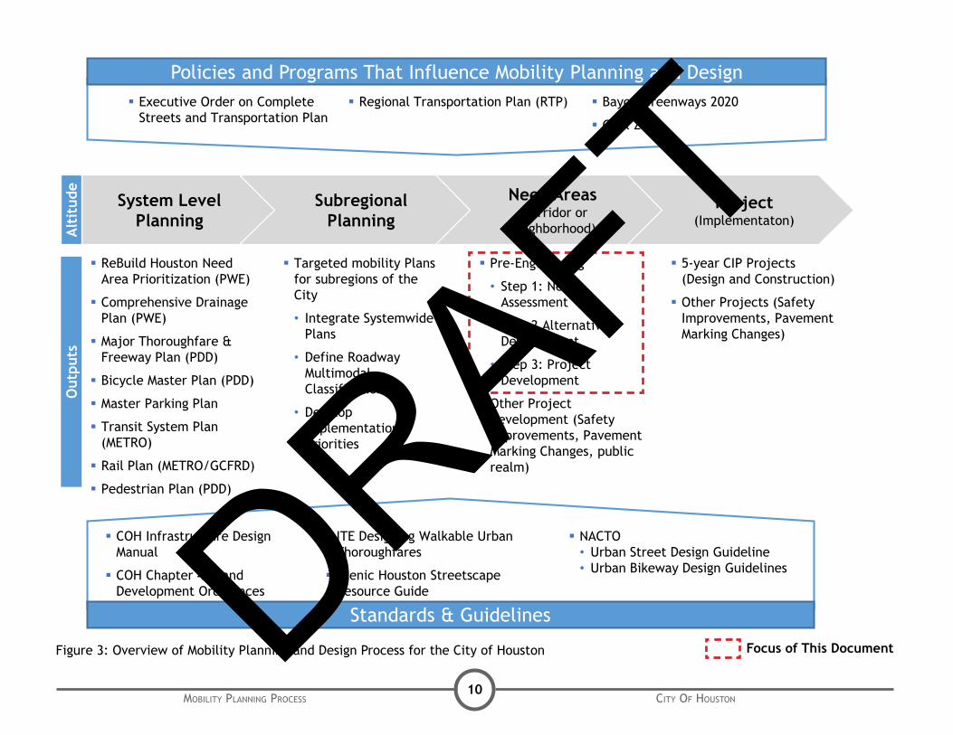
There are four primary planning altitudes at which mobility planning is performed in the City Houston. These altitudes are described below and are shown in Figure 3.
• System: System level plans are city- or region-wide studies that develop top-level strategic plans. System level plans should define goals and outcomes and define a set of specific high-level recommendations that cover the extent of the city. Some components of a System level plan may be developed to more specific detail to support implementation. Examples of System level planning include the Major Thoroughfare and Freeway Plan, the Bicycle Master Plan, a regional drainage plan or a transit system plan. These plans must be integrated at a project level to create true Complete Streets as shown in Figure 1.
• Subregional: Subregional plans provide a more focused look at section of the City to allow a more integrated approach to all of the mobility and infrastructure components in the area. Subregional plans typically incorporate the various inputs from the System level planning efforts to define outputs like Figure 1: Layering of System PlansDRAFT

Mobility Planning Process city of Houston9
Multimodal Classifications for corridors that are aligned with the type of roadway design that may be implemented either through roadway reconstruction or operational retrofits to existing roadways. Figure 2 shows and example of a Subregional Plan output for the Crosstimbers Street corridor. The City has completed several specific Subregional plans, either as the lead client or in partnership with agencies such as the Houston-Galveston Area Council or METRO. Studies have covered areas such as the Heights, East End and Near Northwest. The Planning and Development Department is typically the lead department for Subregional planning, with support from Public Works and Engineering. Other planning efforts such as Livable Centers studies, Special District plans, and Management District plans may be developed a subregional altitude.
• Need Area (Corridor or Neighborhood): Need area plans target a specific corridor or local area of the City such as a neighborhood or subdivision. Need areas often have been identified through system or subregional level plans as priority locations where specific projects should be developed. These studies (such as the pre-engineering process) typically assess a need area with the goal of developing specific implementable projects that can be developed to a sufficient level of detail so that they can be budgeted for final design and implementation. The Public Works and Engineering Department is typically the lead for the Need Area studies with support from Planning and Development and other departments as necessary.
• Projects (Implementation): Project plans develop specific projects to sufficient detail so that they can be implemented. This can include engineering design to support bid, contract, and construction through the City’s CIP process or some other project funding process such as H-GAC’s Transportation Improvement Plan (TIP) or grant funds. It may also include operational improvements such as signal or pavement marking modifications that may be performed in-house by City staff.
Figure 2: Example Subregional Plan Output
DRAFT Houston Mobility: Northwest Study80
W Crosstimbers Street is currently a 4-lane divided Major Thoroughfare. It is also one of the few existing corridors within the Study Area with a designated bike lane. Crosstimbers provides an east/west continuation of W 43rd Street. Residences are the prominent development
type along this small portion of the corridor.
Resident and stakeholders for this corridor identified the preservation of the bike lane as a priority.
The multi-modal classification of Crosstimbers is Suburban Boulevard. Crosstimbers should retain the existing bike lane to best accommodate local circulation. For increased safety, an additional five feet from both sides of the right-of-way is warranted. As a continuation of 43rd Street, a High Frequency Transit route is recommended along the corridor. With this addition, special attention should be given to enhancing the
pedestrian realm.
W Crosstimbers StreetEXISTING CONDITIONS: FUTURE CONDITIONS:
Existing Lanes 4 MTFP Designation T-4-90
Existing Counts Range 16,400-18,300 Future Volume Range 25,000-42,000
Right-of-Way 80’ Proposed MMC Suburban Boulevard
Median/CTL/Undivided Median Median/CTL/Undivided Median
Bike Lane
Bike Lane
Pedestrian Zone
Pedestrian Zone
Travel Lane
Travel Lane
Travel Lane
Travel Lane
Median
Key Factors
Existing Condition Identified Needs Future Vision
Possible Option(s):
N. Main
IH 45
Shepherd
Yale
Airline
[
*Recommended High Frequency Transit
Each of these altitudes develops useful components of a holistic planning and design process that should incorporate the policy decisions set by City of Houston elected officials, such as the Executive Order for Complete Streets and be informed by input from community engagement. They should also utilize City standards, such as the Infrastructure Design Manual, and best practice guidelines identified by the City. Figure 3 identifies important policy inputs and City Guidelines. The following section of this document outlines in further detail the process for the Need Area and Project altitudes and how Complete Streets should be integrated into the process.DRAFT
Mobility Planning Process city of Houston10
System Level Planning
SubregionalPlanning
Need Areas (Corridor or
Neighborhood)
Project(Implementaton)
ReBuild Houston Need Area Prioritization (PWE)
Comprehensive Drainage Plan (PWE)
Major Thoroughfare & Freeway Plan (PDD)
Bicycle Master Plan (PDD)
Master Parking Plan
Transit System Plan (METRO)
Rail Plan (METRO/GCFRD)
Pedestrian Plan (PDD)
Policies and Programs That Influence Mobility Planning and Design
Standards & Guidelines
Executive Order on Complete Streets and Transportation Plan
COH Infrastructure Design Manual
COH Chapter 42 Land Development Ordinances
Bayou Greenways 2020
Goal Zero
ITE Designing Walkable Urban Thoroughfares
Scenic Houston Streetscape Resource Guide
NACTO • Urban Street Design Guideline• Urban Bikeway Design Guidelines
Targeted mobility Plans for subregions of the City
• Integrate SystemwidePlans
• Define Roadway Multimodal Classifications
• Develop Implementation Priorities
Pre-Engineering
• Step 1: Needs Assessment
• Step 2 Alternative Development
• Step 3: Project Development
Other Project Development (Safety Improvements, Pavement Marking Changes, public realm)
5-year CIP Projects (Design and Construction)
Other Projects (Safety Improvements, Pavement Marking Changes)
Regional Transportation Plan (RTP)
Alt
itud
eO
utpu
ts
Figure 3: Overview of Mobility Planning and Design Process for the City of Houston Focus of This DocumentDRAFT

Mobility Planning Process city of Houston11
ABOVE: COH Street Surface Assessment Vehicle
Need Area Planning (Pre-Engineering)
As part of ReBuild Houston, the City of Houston has developed the 10-year 5+5 planning process for Street, Traffic and Drainage capital projects. The term “5+5 Plan” is derived from:
• The first 5 years (Programming: Years 1-5) of the 10-year plan is known as the 5-Year Capital Improvement Program (CIP). The set of projects to be implemented are limited by the available funding in each budget year.
• The second 5 years (Planning : Years 6-10), or “+5 Plan”, is a planning tool that identifies the highest need areas with a process in place for a cost-effective, defined project to advance into the 5-Year CIP. As a result, this “+5 Plan” allows for a much more detailed and objective planning process that complements the City’s established 5-Year CIP.
The 5+5 Plan formalizes the process that the City had largely been using to develop a prioritized set of capital improvement projects to implement over a 5 year budget horizon. This is documented in “Capital Improvement Plan Process Manual for Infrastructure Programs” available on the City’s Rebuild Houston website (http://www.rebuildhouston.org/).
Over time, all drainage, local street and major street projects that are in the CIP should have been vetted through the planning process identified in the 5+5 Plan. The City terms the assessment of need areas and the development of Candidate projects for the CIP through the +5 Plan as Pre-engineering.
Typically, separate Pre-engineering projects are developed for different need areas classified as drainage, local or neighborhood streets, or Major Thoroughfares. These need areas have been identified for study based on a qualitative prioritization process that incorporates data collected by the City through sources such as a comprehensive Pavement Condition Rating and 3-1-1 reports and historical maintenance and drainage issues. Need areas may also be identified through other System level plans and through input from District Council members.
CITy of housTon PlannIng ProCessThe pre-engineering process identifies and scores Candidate Projects for implementation through the CIP. The project scores are based on the benefits they generate in categories including mobility, safety, drainage, utilities as well as an estimate of the benefited population and the project cost. These scores are used to prioritized projects to be included in the CIP.
In the near term there may be defined and funded projects that were developed prior to the advent of ReBuild Houston and the pre-engineering process and these may need to be assessed for alignment with the Complete Streets plan as they move toward implementation.
The following section outlines the proposed Pre-engineering Process for FY2015 and beyond. The City of Houston is working to increase community input into the development of specific candidate projects through pre-engineering. This will build awareness of future projects and engage neighborhoods on how major capital projects that will impact them are developed.
The process is also intended to incorporate the Complete Streets Policy more explicitly into the development of Candidate Projects and support consistent project development.
DRAFT

Mobility Planning Process city of Houston12
The Pre-engineering Process
Figure 4 shows the Pre-engineering Process Flow Chart broken down into its specific components. For each of the components, an estimated duration, proposed scope, and defined deliverables have been developed to support Engineers in the development of Candidate Projects. Overall it is estimated that the Pre-engineering process should take 16 to 20 weeks based on previous projects. Additional time may be required to incorporate Community Engagement and Complete Streets alternatives into the process. At appropriate interval, community meetings may be conducted for each need area to gather feedback on needs and issues from the community and potentially share the findings and recommendations from the study.
Planning 1 (P1):
Define Need Areas, Problem Definition & Conceptual Alternatives
Duration: 8-10 weeks
Scope:
1.1. Project Management - The Engineer shall perform project management including:
1.1.1. Coordination with COH Staff and any subconsultants
1.1.2. Appropriate project documentation
1.2. Data Collection, Coordination & Review
1.2.1. The Engineer shall collect and review necessary data and previous studies related to the study area and vicinity for the completion of the Pre-Engineering. A checklist of data to be collected and sources is included in Appendix A of this report
1.2.2.The Engineer shall coordinate with key stakeholders in the process based on the project areas to understand current plans, e.g., METRO on transit plans, Houston Parks Board on Bayou Greenways connectivity and the impact those may have on the corridor context, role in regional transportation networks, and development patterns.
1.2.3. City of Houston Staff should supply the Engineer with appropriate forms that will be required as part of the Pre-
Planning 1 (P1)Define Need Area, Problem Statement and
Conceptual Alternatives
Planning 1 MeetingCOH Review & Concur
with P1 Report
P1 Community OutreachInput on Corridor
Goals & Challenges
Planning 2 (P2)Alternative Development and Recommended
Solution(s); Includes scope, cost & score at Project Level
Planning Review Committee(PRC) Meeting
Review & Concur with Planning 2
Planning 3 (P3)Prepare Draft Pre-Engineering Reports
with Candidate Projects/Sub-Projects’ scope,cost, scores and duration
Final Pre-Engineering DeliverablesAddress comments and Finalize Pre-engineering
Reports and submit all supportingdata and documents
P3 Community OutreachShare Corridor Recommendation
COH Review of Draft Pre-Engineering Reports
Yes
Yes
No
No
Figure 4: Pre-engineering Process Flow ChartDRAFT

Mobility Planning Process city of Houston13
engineering project. A list of these forms can be found in Appendix B of this report.
1.3. Site Visit & Documentation – The Engineer shall perform field visits to the study area and vicinity to photograph and adequately document existing conditions and special concerns. Observations developed from assessment of initial data collection will be field checked.
1.4. Identify Problems for Need Areas and Define Boundary - The Engineer will utilize the readily available information to compare existing conditions along the corridor with current design standards based on the City of Houston Infrastructure Design Manual, or other reference standard as needed, and deficiencies will be documented. Based on the analysis and identification of problems for need areas, the Engineer will also recommend a project boundary for further analysis under Task 2 Planning 2 (P2). This task includes the first project Community Meeting as described in the following section.
1.5. Approaches & Conceptual Alternatives – Based on the identification of problems for the need areas in Task 1.4, the Engineer shall develop a set of applicable tools and approaches to address the need areas. This may include roadway geometry, traffic control, infrastructure improvements, and drainage improvements. Water and wastewater improvements will be developed by COH.
Based on City of Houston Design standards and best practices in roadway and infrastructure design, the Engineer shall identify several conceptual alternatives to address the identified problems in the need areas. The Engineer must explicitly address how the potential alternatives will meet the City’s Policy on Complete Streets. The alternatives will remain high level concept descriptions as part of Planning 1 and will be developed to a more detailed level if advanced to Planning 2/3.
Community Engagement:
A community meeting shall be held towards the end of the Planning 1 phase to present and overview of the pre-engineering process and the findings of the project area assessment. The public will be able to provide input on project goals, issues to be address, neighborhood priorities, potential design tools, and corridor context that can be refined through the Planning 2 step of the pre-engineering process. This step is critical to developing context sensitive street designs in line with community objectives and overall mobility needs.
Deliverables:
• A report shall be developed documenting the findings from the Planning 1 assessment and potential alternatives to be studied in Planning 2.
• The Engineer shall attend a meeting with the City to present the preliminary findings on need areas and conceptual alternatives developed at Planning Meeting 1. The presentation shall also share insights collected through the community engagement meeting.
Complete Streets Policy Integration:
As noted, the Engineer will explicitly address how Complete Streets objectives will be addressed as part of the pre-engineering study. It is the goal of the City to improve transportation choices for users of all ages, abilities and transportation modes through the development of new and reconstructed roadway projects. This means that Complete Streets design components for roadways should be considered for all new roadway projects.
There may be situations where a corridor is evaluated and provision for all travel modes is not warranted. These design decisions should be noted with clear justification and approved by the project manager with the City of Houston as alternatives are developed. DRAFT

Mobility Planning Process city of Houston14
Planning 1 Meeting Review
Duration: 1 week
Objective: The Engineer will present the findings of Planning 1 to the committee of COH staff. The presentation will identify proposed design alternatives to be developed in greater detail through Planning 2. The Engineer will prepare meeting minutes from the meeting which will include the proposed design alternatives for Planning 2, incorporating any feedback provided by City Staff. The COH Project Manager will coordinate with other staff and stakeholders (e.g., METRO, TxDOT) to review the minutes and ensure concurrence on the direction for Planning 2. It is possible that after a review of the need area in Planning 1, the Engineer and COH Staff agree that there is not a sufficient problem to move forward to Planning 2. If that is the case Planning 1 will be the sole component for the Pre-engineering Report for the need area.
Planning 2 (P2):
Alternative Development and Recommended Solution(s).
Duration: 12-14 weeks
Scope:
2.1. Project Management - The Engineer shall perform project management including:
2.1.1. Coordination with COH Staff and any subconsultants
2.1.2. Appropriate project documentation
2.2. Develop Alternatives - The Engineer will develop possible solutions to need areas and develop alternatives including Traffic, Pavement, and Drainage improvements. Schematic plans should be developed for each alternative showing sufficient detail on how the proposed project addresses the problem statement defined in Planning 1. The alternative should also be assessed for how it meets the goals of the Complete Streets Policy in addressing the needs of all users. The City of Houston will provide recommendations for water and wastewater improvements for the need area.
For each alternative, the Engineer will develop a project scope and cost estimates using the most recent list of unit prices provided to the Engineer by City of Houston Staff. A project score should be developed using the guidelines and forms provided by COH.
2.3. Recommend Solution(s) – for the need area, the Engineer shall develop a recommended solution to present to the Planning Review Committee (PRC) from the alternatives developed in Task 2.2.
Deliverables:
• A report shall be developed documenting the findings from the Planning 2 Alternatives and Recommended Solution. The report should include schematic design and typical sections for each alternative, and supporting analysis of mobility and drainage improvements. Project scope, cost estimates and project level scoring should be developed for each alternative.
• Presentation for Planning Review Committee (PRC) Meeting - the Engineer shall attend the Planning Review Committee Meeting with the City to present the findings and recommendations for Planning 2. The Engineer shall present a handout and presentation to the City summarizing the alternatives and recommended solution. After the meeting the Engineer should provide meeting minutes summarizing the meeting discussion.
• Summary Meeting Minutes for COH Meetings
Community Engagement:
No additional public outreach is proposed for Planning 2. It may be advisable that additional outreach is required or potentially beneficial to ensure that the project alternatives that have been developed to assess community support and potential improvements that could be made. The need for additional community engagement is based on the judgment of the Engineer and the COH Project Manager.
Complete Streets Policy Integration:
Each alternative developed as part of Planning 2 should be assessed to determine how the alternative addresses the goals of the Complete Streets Policy. While recommended alternatives should comply with the requirements of the City of Houston Infrastructure Design Manual, DRAFT

Mobility Planning Process city of Houston15
additional best practice guideline documents should be reviewed to develop the best alternatives for each need area context. The following References and Guidelines may be useful to developing need area alternatives and recommendations in line with the goals of Complete Streets, but should not be considered an exhaustive list:
• ITE Recommended Practice, Designing Walkable Urban Thoroughfares: A Context Sensitive Approach.
• NACTO Urban Street Design Guide (http://nacto.org/usdg/)
• NACTO Urban Bikeway Design Guide (http://nacto.org/cities-for-cycling/design-guide/)
• Scenic Houston Streetscape Resource Guide
The Engineer should also refer to the Complete Streets Considerations for the Development of Alternatives section of this document. This should be reviewed for some high level design guidance to be considered as corridor alternatives are developed. This will allow the development of Candidate Projects that best meet the goals of the Complete Streets Policy.
P2 Meeting - Planning Review Committee (PRC)
Duration: 2 weeks
Objective: The Engineer will present the findings and recommendations of the Planning 2 assessment to the PRC. The presentation will include proposed design alternatives developed through Planning 2. The presentation will include recommended roadway cross-section(s), schematic design, utility improvement cost estimates and project scoring. The Engineer will prepare meeting minutes from the meeting which will include the recommended design alternatives to move forward for Candidate project development in Planning 3, incorporating any feedback provided by City Staff. The COH Project manager will coordinate with other staff to review the minutes and ensure agreement of the Candidate Project for Planning 3.
Planning 3 (P3):
Candidate Project Development and Final Report
Duration: 6 weeks
Scope:
3.1. Project Management - The Engineer shall perform project management including:
3.1.1. Coordination with COH Staff and any subconsultants
3.1.2. Appropriate project documentation
3.2. Prepare Draft Pre-Engineering Report - After the City selects the best alternative solution during the Planning Review Committee Meeting, the Engineer shall develop candidate project(s) with defined and detailed scopes, cost estimates and benefits. These will be developed into a Draft Pre-Engineering Report including Executive Summary, Description of Need Area, Problem Definition/Identification, Candidate Projects/Sub-Projects scope, cost, scores and duration and Candidate Forms (See Appendix B). This phase also includes a second community meeting to share to project recommendations. This meeting is described in the following section of the scope. Project materials will also be made available online to allow people unable to attend the meeting to review.
3.2.1. Candidate Projects Exhibits
3.2.2. Appendices for Pre-Engineering Report
3.3 Address COH and community comments on Draft Pre-engineering Report
3.4. Finalize Pre-Engineering Reports - Engineer shall address comments on the Draft Pre-Engineering Report and prepare Final Pre-Engineering Report. Responses to Comments will be included in Final Deliverable. The Engineering Report will be signed and sealed by a Licensed Professional Engineer. It will include the prioritized alternative solutions and defined projects. The Engineer will also submit all supporting data and documents.DRAFT

Mobility Planning Process city of Houston16
Community Engagement:
A second community meeting will be held after the PRC Meeting to share project recommendations with the community. The meeting should focus on how the recommended project aligns with the issues and goals developed through the P1 phase of the project. Project materials may also be made available online to allow more community awareness and input on proposed project recommendations.
Deliverables:
• Draft Pre-Engineering Report
• Final Pre-Engineering Report
Complete Streets Policy Integration:
The Final Pre-engineering Report should include a statement about how the Candidate Project(s) address the City’s Complete Street Policy. Final report should document consideration of and justification for all modes.
DRAFT

Mobility Planning Process city of Houston17
samPle sChedule
Development of a Pre-Engineering Study
To following Figure 5 is a sample project schedule for the development of a Pre-engineering study for one need area aligned with the scope provided in the previous section. An Engineer may have several need areas to address concurrently and schedules should be aligned where possible. The schedule may be influenced by deadlines and milestones, such as the need to complete projects in time to integrate into project prioritization for inclusion in the CIP. The final schedule should be developed based on the specific need area and contexts and agreed to between the Engineer and the COH Project Manager.
Sample Pre-Engineering Project ScheduleCity of Houston WBS No. XYZWork Order No. X: Need Areas _________________
0 1 2 3 4 5 6 7 8 9 10 11 12 13 14 15 16 17 18 19 20 21 22 23 24 25 26 27 28 29 30 31 32
NTP1.1 Project Management1.2 Data Collection & Review1.3 Site Visit & Documentation
1.4Identify Problems for Need Areas and Define Boundary
1.5 Approaches & Conceptual AlternativesFinalize Planning 1 DeliverablesP1 Community Meeting Planning 1 Meeting and COH Review
Planning 22.1 Project Management
2.2Develop Alternatives including with scope, cost & score at Project Level
2.3 Recommend Solution(s)Finalize Planning 2 DeliverbalesPlanning Review Committee Meeting and COH Review
Planning 33.1 Project Management
3.2Prepare Draft Pre-Engineering Reports with Candidate Projects/Sub-Projects’ scope, cost, scores and durationPost PRC Community Meeting
3.3Address comments on Draft Pre-Engineering Report
3.4Finalize Pre-engineering Reports and submit all supporting data and documents
(Target Completion)
Month 8Month 3 Month 4 Month 5 Month 6 Month 7Task Description
Planning 1Task #
Month 2
Firm Name:______________________
Month 1
Community Meetings COH/Consultant Meetings
Figure 5: Sample Pre-engineering Project ScheduleDRAFT

Mobility Planning Process city of Houston18
CIP Projects
Candidate project developed through the pre-engineering process are prioritized for funding and implementation based on the project scoring developed through the pre-engineering process. Projects with high Candidate Project Scores move forward to the CIP process with the Engineering Branch for design activities. Once designed, projects can move forward to implementation.
While Complete Streets outcomes are important considerations throughout the design process, the most critical time is during the development of the Preliminary Engineering Report including the following major components.
• Executive Summary
• Project Introduction
• Existing Conditions and Findings From Phase I Design Activities
• Proposed Conditions, Evaluations, and Recommendations
• Estimated Construction Cost
• Relevant Maps And Figures - Includes 30% Plan & Profile Design Drawings.
At this point many of the major decisions about roadway geometry, right-of-way, drainage, and the pedestrian realm will be made to allow the project to move to final design. The current Preliminary Engineering Report Contents and Process Overview can be found in Appendix D of this document.
As projects in the City design process have not all gone through the proposed pre-engineering process described in the previous section of this document, incorporating the goals of Complete Streets Executive Order and taking a more context sensitive design approach to project design will require tailoring the approach to ensure goals are met.
The following represent several specific steps that should be incorporated into the scope of work to address Complete Streets.
• Review Best Practice Context Sensitive Design Standards as part of Reading Period and review of pre-engineering report including:
• Design of Walkable Urban Thoroughfares - an ITE Recommended Practice
PrelImInary engIneerIng rePorT• NACTO Urban Street Design Guide
• Scenic Houston Streetscape Design Guidelines
• Complete Streets considerations identified in the following section of this document
• City of Houston Infrastructure Design Manual Chapter 10
• Conduct a Community Meeting prior to the progress meeting with City staff to determine design direction for development to 30% Plan and Profile. Findings from existing conditions should be presented and proposed design concepts should be presented for feedback. The public should be able to provide input on potential design concepts, neighborhood priorities, and context that can be incorporated in the Preliminary Engineering plan. An overview of project timeline should be provided for the public. This step is critical to developing context sensitive street designs in line with the goals of the Complete Streets EO.
• Additional public engagement may be necessary based on the project scope, alternatives and community involvement. This should be determined by the City’s Project Manager and the project Engineer.
• Recognize the role the proposed project played in various transportation networks to ensure that multimodal mobility is addressed in the design e.g., METRO’s Transit System Plan, the City’s Bicycle Master Plan
• Coordinate with PWE and P&D departments to identify the multi-modal classification and context of the project corridor using a process-based approach that takes into account the likelihood of an area evolving over time with redevelopment or changes in land use. If applicable, refer to the multi-modal classification and context recommendations in the sub-regional mobility but recognizing that the recommendations will be further refined as part of the Houston Complete Streets and Transportation Plan (currently under development).
• Utilize Complete Streets Checklist to address how the proposed design concept for the street addresses the Complete Streets EO.DRAFT

Mobility Planning Process city of Houston19
As engineers work through the process of developing alternatives during the pre-engineering process or refining designs in preliminary engineering for CIP implementation, there are multiple design considerations that should be addressed in developing Complete Streets. To develop a street project that incorporates context sensitive design principles and addresses the goals of the Complete Streets policy requires thinking at both the streets role at the system level and about specific details related to the local context of the project.
To support this type of approach, a set of design consideration have been identified below. These are intended to provoke thoughts and ideas as design alternatives are developed. It is worth noting that complete streets do not mean all streets should be designed the same and context is very important to which of the below are relevant to a particular project. This is also not intended to be an exhaustive list and engineers are encourage to bring other ideas and best practices to the development of projects.
As the City of Houston is refining the Infrastructure Design Manual some of these may not be in line with current guidelines, and some design ideas would require discussions with the City and potentially a variance or notice of approval to proceed.
Design Control Considerations
• Design speed - Identify appropriate design speed for the corridor based on context. Design speeds should be set in line with the target speed for drivers along the corridor and aligned with the desired posted speed limit.
• Design vehicles - Complete streets are typically designed to accommodate the largest vehicle that is frequently present, not necessarily the largest possible vehicle.
• Level of service – Level of service is the traditional metric for evaluating an intersection, but typically only measures one aspect of its performance, vehicle delay. Where improvements to vehicular delay create a significant negative impact on other modes of travel, alternatives should be considered. The most
ComPleTe sTreeTs ConsIderaTIons for The develoPmenT of alTernaTIves
recent Highway Capacity Manual outlines some potential options for assessing Level of Service for cyclists, pedestrians and transit users that are useful in understanding trade-offs in various design alternative.
• Sight distance - Designing roads with lower target speeds reduces the size of intersection sight triangles required and shortens vehicle stopping distances.
Roadway Design Considerations
• Lane widths - the updated 2015 City of Houston IDM recommends 11’ typical width for standard travel lanes. There may be appropriate locations where narrower 10’ lanes are preferred. Engineers should consider a range of appropriate lanes widths, especially in locations where constrained right-of-way makes inclusion of pedestrian and bicycle facilities more challenging and areas where travel speeds are intended to be lower. Narrower travel lanes (less than 11’) may also be appropriate to minimize the impact of ROW acquisition on adjacent properties. Design exceptions should be required for roadways where travel lanes are wider than 11’ on complete streets.
• Innovative design alternatives (e.g., roundabouts, multiway boulevards) – While these approaches to roadway design have long histories such that it is hard to call them innovative, their use in Houston has been minimal. Design alternatives should consider these and other design options where they would support the local context. Roundabouts can be appropriate to address complex intersections or safety issues. Where right-of-way is available, a multiway boulevard featuring a central thoroughfare for higher-speed through movements separated from one-way access roadways by landscaped medians can be used in place of a typical high volume thoroughfare. Friction is reduced for through traffic and transit vehicles because driveway access, turns, and on-street parking are accommodated on the access roadways. The access roadways also create a safer, more comfortable environment for pedestrians and cyclists since they are separated from high speed traffic.DRAFT

Mobility Planning Process city of Houston20
• Access management and driveway consolidation - Roadway reconstruction represents and opportunity to implement access management strategies such as driveway consolidation, shared access and redesign of medians and median openings. This can also bring corridors more in alignment with city access standards and provide more space and few driveway crossings for pedestrians.
• Neighborhood streets - Neighborhood streets can be designed as complete streets by designing to maintain low speeds and volumes on these streets, while reinforcing their shared nature for vehicles, bicycles and pedestrians.
Pedestrian & Bicyclist Considerations
• Safe crossings/ADA - On complete streets, pedestrian crossing distances are typically the minimum necessary to provide the appropriate capacity for the conflicting movements. Pedestrian ramps and other amenities should comply requirements set by the American with Disabilities Act (ADA) and aligned with IDM.
• Minimum vs. preferred sidewalk width - City of Houston IDM requires a 5’ minimum sidewalk on major thoroughfares and 6’ sidewalks on Transit Corridors. These are minimum width and wider should be considered, especially where significant pedestrian use exists or may occur in the future such as near schools or in commercial districts.
• Bikeway treatments and design riders - Context sensitive design takes into account users of a broad range of ages and abilities. On corridors that have bicycle facilities, the design of these should consider a range of bicycle treatments and effort should be made to create dedicated space for cyclists through the use of bicycle lanes, buffered lanes, and dedicated bikeways or cycletracks. When well designed and located, these facilities have been shown to greatly increase cycling rates by attracting a broad range of cyclists, even many who are uncomfortable cycling in mixed traffic. Other design element such as bike boxes, bicycle signals and green pavement markings should also be considered.
Transit Considerations
• High frequency transit – Transit lines (both bus and rail) that run every 15 minutes or better connecting to activity centers and higher density development generally attract high ridership. Transit riders are always pedestrians (or cyclists) on one or both ends of their trips. Accordingly, wider sidewalks, expanded bus stops, and other pedestrian-oriented design features should be included along corridors with high-frequency transit service.
• Bus stop spacing - The redesign of streets represents an opportunity to optimize the spacing and locations of bus stops. Optimal spacing depends on type of service provided along the corridor. For medium and high frequency services (30 minutes or better), which typically are designed to attract high ridership, spacing of about one quarter mile is desirable to maintain higher average vehicle speeds. For lower frequency services (over 30 minutes) closer spacing of around one eighth of a mile is acceptable since these services are intended to maximize access to the service.
• Bus stop locations and transfers - Generally, bus stops should be placed in accordance with the following priorities until the desired spacing is reached:
1) Major cross streets with connecting bus service
2) Other major cross streets
3) Cross streets with safe crossing locations (e.g., signalized)
4) Other cross streets with legal crossing locations
5) Major ridership generators in between intersections
6) Other intersections
• Bus stop placement - Coordination with METRO should determine bus stop placement in accordance with their current guidelines. On major bicycle corridors, bus stops should be placed to minimize bus- bicycle conflicts where possible.
• Bus stop design - In addition to meeting ADA accessibility guidelines, bus stops should be comfortable for users. Coordination with METRO should provide careful consideration to locations where passengers may alight from both the front and rear doors of the DRAFT

Mobility Planning Process city of Houston21
bus and to various bus lengths (e.g., Articulated buses) and pads should be provided where possible. Shelters should be located as far back from the street as possible; ten to fifteen feet from back of curb is optimal. Shelter placement should be considered when determining if and how much additional right-of-way is required for the project.
Drainage & Landscaping Considerations
• Drainage - Low impact development techniques can be complementary to complete streets design through effective use of landscaping, construction materials and drainage infrastructure. Low impact development approaches can also have significant benefits for water quality.
• Landscaping - Incorporating landscaping into street and drainage designs can play an important role in creating a complete street. Shade trees make a much more pleasant walking environment during Houston’s warm summers. Landscaping can also be used as an effective buffer between bicyclists, pedestrians and fast moving vehicular traffic.
• Landscaping - While landscaping and other pedestrian realm enhancements may not be part of a roadway project, long term planning to allow future landscaping upgrades should be considered. This can include the leaving space for future enhancements such as trees or lighting that would not be in conflict with mobility along the corridor.
Development & Right-of-Way Considerations
• Context/redevelopment - Market demand and changes to Houston’s development code are leading to higher density land use in many parts of the city. Higher density typically correlates with greater demand for non-motorized transportation since it tends to bring more destinations within close proximity of residences, schools, and other trip generators. As the life of a rebuilt thoroughfare will be decades long, design should take into account development trends and likely future context, especially in areas where denser development will lead to different demands on the street than may exist today.
• Outside entity plans - During project development it is important to understand current development plans and opportunities along the corridor. This will support design decisions as well as identify right-of-way acquisition opportunities adjacent to the project. Coordination with Management Districts, TIRZs, housing agencies, schools, METRO, TxDOT, Harris County and other entities with right-of-way or development plans along the corridor is also recommended.
• Right-of-way - It is important that right-of-way be acquired to support long term needs identified in the Major Thoroughfare & Freeway Plan. It may be advisable to design near term street to meet nearer term need in a more context sensitive manner in line with current demands while leaving flexibility to expand roadways to meet future needs. Also, where possible consideration of design alternatives such as narrower travel lanes can minimize the impact of adjacent developed properties. Small acquisitions such as corner clips at signalized intersection can provide space for items like signal equipment, utility pole and bus shelters, keeping them out of the sidewalk and other pedestrian areas.
ABOVE: Design Guidelines and Recommendations from NACTODRAFT

Mobility Planning Process city of Houston22
Mobility Project
Development StepRecommended Community Outreach Lead
Systems • Broad Citywide/regional input on goals and outcomes through town halls, neighborhood meetings, online tools/surveys.
• Planning & Development Department (PDD)
• Support: PWE
Subregional • Broad Subregional area input on goals and outcomes through town halls, neighborhood meetings, online tools/surveys.
• Planning & Development Department
• Support: PWE
Need Area (Pre-Engineering)
• Planning 1 Meeting: Build project awareness, understand issues, challenges and goals and collect feedback on context and potential design solutions.
• Additional public outreach may be required and should be determined between project engineer and the City’s project manager.
• Infrastructure Planning
• Support: Engineering Design, Traffic & Operations, PDD
Project (Funded CIP Projects to be Designed)
• Preliminary Engineering Meeting: Build project awareness, understand issues, challenges and goals and collect feedback on context and potential design solutions to inform PER development.
• Additional public outreach may be required and should be determined between project engineer and the City’s project manager.
• Infrastructure Planning
• Support: Engineering Design, PDD
Project (Funded CIP Projects Completely or Substantially Designed (60% or greater) or set for bid)
• Meeting: Provide project overview and design elements (e.g., typical section), share project design schedule, and address community questions.
• Outreach will be tailored to project scope and timeline.
• Engineering Design
• Support: Infrastructure Planning
ABOVE: Public Input Heights - Northside Mobility Plans
Tailored Outreached for Each Planning Step
The City of Houston is working to increase the level of community engagement as part of the ReBuild Houston program. This will build awareness of upcoming projects, support community understanding of the ReBuild Houston program goals and timeline, and allow communities to be more engaged in the design outcomes for Houston’s Streets. The table below identifies the recommended outreach approach for each Mobility Project Development step. The approach should be tailored based on the project timeline, scope and context. For example, projects through historically or culturally sensitive locations or on thoroughfares with fronting residential development may require additional community engagement tailored specifically to that aspect of the project.
CommunITy ouTreaCh
DRAFT

Mobility Planning Process city of Houston23
CommunITy meeTIngs and ouTreaCh Tools
Community Meeting 1 (During P1 Phase)
Meeting Objectives
• Share overview of 5+5 Planning process including both pre-engineering and CIP including where the project is in the process
• Present findings from existing conditions and identify needs/issues/challenges of the study/project
• Help define community’s overall vision (short and long term) and values (desirable elements) using a predefined set of tools
• Outline the next steps and how they can find information regarding the study
• Provide opportunity for Q&A and written feedback (e.g., study area maps, comment cards)
Online Project Information• 5+5 Planning process overview
• Meeting presentations
• Map based feedback tools
• Project Recommendations
• Complete Streets Project Checklist
• Email List Signup
Community Meeting 2 (Post-PRC)
Meeting Objectives
• Share overview of 5+5 Planning process including both pre-engineering and CIP including where the project is in the process including overview of project prioritization
• Present recommended project(s) that are planned to move forward for consideration in the CIP
• Share how recommended project aligns with community context, feedback and goals while balancing regional resources
• Outline the next steps and how they can find information regarding the recommended projects
• Provide opportunity for Q&A and online feedback (e.g., project plan schematic, comment cards
The pre-engineering process has two community outreach phases which will be critical to the development of context sensitive design projects. Communities will have a strong understanding of the current context of a corridor and the mobility and drainage issues they face. Providing multiple opportunities and channels for community members and other stakeholders to learn more about the ReBuild Houston 5+5 planning approach, the potential toolbox of design options, and the regional demands of a corridor will help the City work with the community to develop better projects to move forward to implementation. In addition to community meetings, online tools can be used to support and broaden the outreach, and to get more project feedback. Meeting and online objectives and tools are provided below.
DRAFT

Mobility Planning Process city of Houston24
examPle ComPleTe sTreeTs CheCklIsT
Corridor: Limits (From/To):
Existing ADT 2040 ADT Assummed Growth Rate (%)
Context: Existing MTFP Classification
Existing Right-of-Way (ft) Major Destinations on Corridor
Multimodal Classification Proposed MTFP Classification
Existing Corridor Stops (#) Existing Average Stop Spacing (ft) Existing Shelter Pads (#)
Proposed Corridor Stops (#) Proposed Average Stop Spacing (ft) Proposed Shelter Pads (#)
Existing Sidewalk Width (ft) Proposed Sidewalk Width (ft)
What is the design vehicle? (e.g., WB-50)
Proposed Parking (South/West side of Street)
Connections to Existing and Proposed Off street Bicycle Facilties (e.g., Bayous and Utility Corridors)
Existing Parking (North/East side of Street)
Existing Parking (South/West side of Street)
Proposed Parking (North/East side of Street)Park
ing
Cont
ext
Des
ign
Crit
eria
Tran
sit
Wal
kBi
ke
Transit Route(s) on Corridor (Route #s and Midday Headways):
Weekday Boardings at Stops Along Corridors: within 200' either side of centerline
Connecting Routes along Corridor:
What would be the maximum distance between dedicated pedestrian crossings on corridor? (ft)
What considerations led to the proposed bike facilities?
What considerations led to the proposed sidewalk width?
Existing Bike Facilities (type, surface, width):
Proposed Bike Facilities (type, surface, width)::
Bike Master Plan Designation:
Existing # of Lanes (Travel, Turn, Parking):
Proposed # of Lanes (Travel, Turn, Parking):
Existing Travel Lane Width(s) (ft):
Proposed Travel Lane Width(s) (ft):
What considerations led to the proposed number of lanes and lane widths?
City of Houston Mobility PlanningComplete Streets Planning Consideration Checklist
What design decisions were influenced by designing to the above speeds?
Target Speed/Operational Speed Limit/Design Speed (mph)
DRAFT

Mobility Planning Process city of Houston25
ABOVE: Scenic Houston Streetscape Design Guidelines
Utilities aligned in R-O-W
Pedestrian scaled lights
Maximum pedestrian walk provided
Proper space allowed for planting street trees
27
The following Information is available as appendix information to this report.
• Appendix A: Pre-engineering Data Collection Checklist• Appendix B: Pre-engineering Form Checklist• Appendix C: Executive Order 1-15 Complete Streets• Appendix D: Preliminary Engineering Report Contents And
Process Overview
aPPendIx
DRAFT

Mobility Planning Process city of Houston26
# Data to Be Collected Data Type Source Source Location* Collected
1 Aerial SID Files COH Request from COH Staff
2 LiDAR LiDAR H-GAC Request from H-GAC Staff
3 Parcel Boundaries Shapefile HCAD http://pdata.hcad.org/GIS/
4 Land Use and Land Value Shapefile HCAD http://pdata.hcad.org/download/index.html
5 Roadway ROW Shapefile HCAD http://pdata.hcad.org/GIS/
7 Roadway Centerline Shapefile COH
8 City of Houston Major Thoroughfare Plan Shapefile COH http://www.houstontx.gov/planning/mobility/MTFP.html
9 Crash Data Data Set TxDOT CRIS Database
Request from H-GAC Staff
10 Pavement Condition Ranking (PCR) (2011 or most recent)
Shapefile COH Request from COH Staff (also category ranges from city)
11 Bikeways Shapefile COH http://www.gims.houstontx.gov/
12 Transit Ridership - By Route Data Set METRO http://www.ridemetro.org/News/Documents/RidershipReport.aspx
13 Transit Ridership - By Stop on Corridor Data Set METRO Request from METRO
14 Transit Stop Locations Shapefile METRO Request from METRO
15 Transit Route(s) on Corridor Shapefile METRO Request from METRO
16 Bridge Conditions Data Set COH Request BRINDSAP Report from COH Staff
17 CIP Records Shapefile COH http://www.gims.houstontx.gov
18 Turning Movement Counts Data Set Project Team Collected by Project Team at selected intersections (Confirm locations with COH Project Manager
19 Existing Traffic Counts Data Set Project Team Collected by Project Team at selected intersections (Confirm locations with COH Project Manager
20 Historical Turning Movements Data Set COH http://www.gims.houstontx.gov/
21 Historical Turning Movements Data Set COH http://www.gims.houstontx.gov/
22 Existing ADT - Existing V/C Data Set Regional Travel Demand Model
Request from COH Staff
*Source locations may change; Also confirm with COH Staff that most recent data files are available and downloadable via GIMS website (http://www.gims.houstontx.gov/)
Data Inputs to Pre-EngineeringThe following represents the typical set of data that should be collected for a pre-engineering study for a need area. Actual data requirements should be determined based on discussion with COH staff. Engineers should also plan complete site visit(s) to assess field conditions and potential recommendations as part of the process. This Checklist should be filled out and submitted with the Planning 2 Submittal to City of Houston Staff for review.
aPPendIx a: Pre-engIneerIng daTa ColleCTIon CheCklIsT
DRAFT

Mobility Planning Process city of Houston27
*Source locations may change; Also confirm with COH Staff that most recent data files are available and downloadable via GIMS website (http://www.gims.houstontx.gov/)
# Data to Be Collected Data Type Source Source Location* Collected
23 Future ADT - Future V/C Data Set Regional Travel Demand Model
Request from COH Staff
24 SWMP-Comprehensive Drainage Plan (CDP) Data Set COH Request from COH Staff http://www.swmp.org
25 Storm Drainage System Data (pipes, boxes, manholes, Inlets, and etc.)
Shapefile COH Request from COH Staff Lambert Grid sections available on GIMS (http://www.gims.houstontx.gov/)
26 Flood Complaints (311,NFIP, single point loss, FEMA, repetitive loss etc..)
Shapefile COH Request from COH Staff Lambert Grid sections available on GIMS (http://www.gims.houstontx.gov/)
27 Water System Data (lines, age, materials, and etc..) Shapefile COH Request from COH Staff Lambert Grid sections available on GIMS (http://www.gims.houstontx.gov/)
28 Wastewater System Data (Lines, age, materials, manholes, depth, and etc..)
Shapefile COH Request from COH Staff Lambert Grid sections available on GIMS (http://www.gims.houstontx.gov/)
29 Wastewater Complaint Data (Stoppages, Overflows, and Odor)
Shapefile COH Request from COH Staff
30 Water Quality Complaint Data Shapefile COH Request from COH Staff
31 Wastewater Work Order and Maintenance History Data Set COH Request from COH Staff
32 Water Work Order and Maintenance History Data Set COH Request from COH Staff
33 Water Infrastructure Replacement Prioritization (WIRP)
Data Set COH Request from COH Staff
34 Ponding Over 2 Feet Raster COH Request from COH Staff GIMS includes Ponding Layer for reference (http://www.gims.houstontx. gov/)
35 Two Foot Contours Shapefile HGAC http://www.h-gac.com/rds/gis-data/gis-datasets.aspx
36 Easements Shapefile HCAD http://pdata.hcad.org/GIS/
37 Record Drawings Drawings COH Obtain Plan Number from water, wastewater, and drainage Shapefiles Request Record Drawing from COH Staff based on Plan Number
38 Telecommunications Information Request to be submitted to private telecommunications companies
39 Pipeline Information Request to be submitted to private gas and pipeline companies
40 TxDOT Bid Values Data Set TxDOT Request from COH Staff
41 Existing Mobility Plans Reports COH - PDD PDD Staff (http://www.houstontx.gov/planning/mobility/)
42 Metro’s New Bus Network Map Metro www.ridemetro.orgDRAFT

Mobility Planning Process city of Houston28
# Data to Be Collected Source Collected
1 Aerial COH
2 Total Project Cost Estimate Breakdown COH
3 COH Rebuild Funds to Calculate Candidate Project Priority Score COH
4 Form Y COH
5 Modified 410 Forms - Part B COH
Data Inputs to Pre-Engineering
The following represents the set of Forms for the Engineer to collect to develop a Pre-Engineering Study. The Engineer should be familiar with these forms early in the process, as this will ensure that work progresses in an efficient way in completing the deliverables to allow candidate projects to be considered for inclusion in the CIP.
aPPendIx b: Pre-engInerIng form CheCklIsT
DRAFT

Mobility Planning Process city of Houston29
4.4 Provide framework for coordination and integration of revisions to current plans, such as, Major Thoroughfare and Freeway Plan, Houston’s Bikeway Plan, with new component plans, and vice versa, in supportive ways to encourage complete streets.
5. SCOPE The Plan will be inclusive of multiple transportation plan components created, adopted and implemented by the City and entities other than the City of Houston. It is intended that those entities will partner with PDD and PWE on the planning and finalization of The Plan as it relates to their specific transportation planning roles. For example, Metropolitan Transit Authority of Harris County (METRO), author of METRO’s Transit Plan, will provide input on The Plan regarding mass transit through a periodic transit plan update. PDD and PWE will integrate all planning efforts for compilation and implementation of the HCSTP.
6. DEFINITIONS There are four new definitions that will need to be defined in certain documents used by PDD andPWE that guide planning, construction and reconstruction efforts of land planners, developers and civil engineers. These documents include the MTFP Policy Statement and PWE’s Infrastructure Design Manual.The new definitions are as follows:Complete Streets – Public roadways that take into account all users, including people who are driving or riding in cars, using mass transit, riding bikes, walking, using wheelchairs, driving or riding in trucks, driving or being transported by emergency vehicles, and being served at their residence or property by other users. Complete streets do not mean that all streets are identical. The complete street concept takes the following variables into account when providing services:
a) People being served at their residence or property by other ROW users.b) People of all ages and abilities, including children, older adults, and persons with
disabilities.c) The function of the road (e.g. local, collector, and thoroughfare) and the level of vehicular,
pedestrian, and bicycle traffic.d) Multi-Modal Classification Street Types.
Houston Complete Street and Transportation Plan – A plan that, at a minimum, includes the Major Thoroughfare and Freeway Plan, Bikeway/Pedestrian Plan, Rail Plan, Multi-Modal Classification Street Type and Master Parking Plan, Bayou Greenway Initiative, Context Report and METRO’s Transit Plan.Multi-Modal Classification Street Type – A public street type classification system that takes into account the functional classification (MTFP designation) and land use context, inclusive of right-of-way width, number of lanes, and traffic volume.
The context of the land use adjacent to the road comprises population and job densities (present and future), projected land use types (residential, commercial, community facility, or industrial), and modes of operation (pedestrian, bicycle, transit, rail, freight and vehicle lanes) can be used as a determinant in identifying Multi-Modal Classifications.
Subject:Houston Complete Streets and Transportation Plan
E.O. No.: 1-15 Page 2 of 5
CITY OF HOUSTON
Executive Order
Subject: Houston Complete Streets and Transportation Plan
E.O. No: 1-15Effective Date: November 1, 2013
1. AUTHORITYArticle II. – Corporate and General Powers, Sec. 4 – Street Powers, of the City Charter of the City of Houston.
2. PURPOSE2.1 To direct City efforts to achieve complete streets, as defined herein, through the planning,
designing, budgeting, constructing, and reconstructing of all transportation improvements while recognizing that complete streets are achieved over time through single projects, new and redevelopment, and through a series of incremental improvements. \
2.2 To build upon recent code and policy improvements such as, Chapter 42 of the Code of Ordinances including the requirement for existing conditions surveys and plans for recently completed and on-going city mobility studies.
3. OBJECTIVES 3.1 Establish a menu of complete street types based upon Multi Modal Classification.3.2 Develop a forecast of street type citywide to complement and extend currently
established plans to create the long range vision of complete streets.3.3 Establish city standards to minimize obstructions in public pedestrian travel ways.3.4 Benefit from community input and thought rendered through reports such as Livable
Center Studies and Scenic Houston’s Streetscape Resource Guide.3.5 Recognize the role streets play in drainage and water quality.
4. PRODUCTS4.1 Provide policies and procedures that shall direct the development of the Houston
Complete Streets and Transportation Plan (The Plan) by utilizing City Mobility Planning efforts conducted by Planning and Development Department (PDD) and the Public Works and Engineering Department (PWE); and by utilizing prior and existing governance and existing planning tools as a basis.
4.2 Provide an overall framework for revision and expansion of City Mobility Planning and deliverables.
4.3 Transition to and then sustain The Plan.
Approved: Date Approved:
11/01/2013
Page 1 of 5
aPPendIx C: exeCuTIve order 1-15 ComPleTe sTreeTs
DRAFT

Mobility Planning Process city of Houston30
Multimodal Classification Plan Current section types Future section type at reconstruction 20 yrs Context Report Land use and development pattern Population and Job growth forecasting 10 yrs
Master Parking Plan Street capacity for parking; metered zones, public lots/garages; residential permit zones
Planned lots/garages 5 yrs
7.3 The Plan’s components have differing planning horizons. Each component would continue to be amended on its own plan horizon – some sooner than others.
8. RESPONSIBILITIES8.1 PDD and PWE along with METRO are responsible for the administration of The Plan’s
components. PDD, through the Planning Commission and City Council, revises and adopts a new MTFP annually. The METRO Transit Plan is updated periodically through the METRO Board’s adoption.
8.2 The parties having component responsibilities will work together when amending and updating their own specific plans in order to remedy conflicts between plans and analyze opportunities to improve comprehensively elements where they converge.
8.3 PWE or Tax Reinvestment Zone design consultants and private development design consultants will propose during preliminary engineering a design concept consistent with the Multi-Modal Classification Street Type as designated in that component plan.
8.4 Additional amenities in the rights-of-way, such as pedestrian lighting, street furniture, etc., will be considered on a case by case basis with PWE approval.
8.5 PWE will refine standards for accomplishment of the objectives and document such standards within the Department’s Infrastructure Design Manual.
COMPONENT RESPONSIBILITY Plan Component Content Management Promulgation of Update
Major Thoroughfare and Freeway Plan
Planning and Development—annual process of general input as established through MTFP Policy; specific input from mobility studies
Council adoption of annual revision after Planning Commission consideration and recommendation
Bikeway/Pedestrian Plan Public Works and Engineering, Planning and Development —annual process, inter-departmental coordination
Public Works and Engineering
Transit Plan METRO
Planning and Development will integrate to Houston Complete Street Transportation Plan after METRO presents Transit Plan to Transportation and Infrastructure Council Committee
Rail Plan Public Works and Engineering with Gulf Coast Rail District Public Works and Engineering
Multimodal Classification Plan Planning and Development—recurring process to receive proposed changes from the public by Policy TBP
Planning and Development
Context Report Planning and Development Planning and Development
Master Parking Plan Public Works and Engineering with Administrative and Regulatory Affairs Departments
Administrative and Regulatory Affairs Departments with support from PWE
Subject:Houston Complete Streets and Transportation Plan
E.O. No.: 1-15 Page 4 of 5
Minor Collector – A public street that accumulates traffic from local streets for distribution into a thoroughfare or major collector. A minor collector typically serves residential uses. Although in some circumstances, it may serve commercial or mixed uses.
Existing definitions below that are contained within this Order are here for the ease of reading the document.Major Thoroughfares – Divided into two classifications; Principal Thoroughfare and Thoroughfare. Major Thoroughfares are those streets designed for fast, heavy traffic, high traffic volume and are intended to serve as traffic arteries of considerable length and continuity throughout the community.
Principal Thoroughfare – Public streets that accumulate traffic from collector streets and other Major Thoroughfares for distribution to the freeway system. They may be a highway and typically provide a high degree of mobility for long distance trips. Thoroughfare – Public streets that accumulate traffic from Collector streets and local streets for distribution through the thoroughfare and freeway system. These streets distribute medium to high volume traffic and provide access to commercial, mixed use and residential areas.
Transit Corridor Streets – Rights-of-way or easements that METRO has proposed as a route for a guided rapid transit or fixed guideway transit system and that is included on the City’s MTFP. Collector Streets – Public streets that accumulate traffic from local streets for distribution to the Major Thoroughfare streets. A Collector Street may be a Minor Collector or a Major Collector.
Major Collectors – Public streets that accumulate traffic from local streets and Minor Collectors for distribution to the Major Thoroughfare. A Major Collector Street may have commercial, residential or have mixed uses abutting.
7. COMPONENTS7.1 The Plan, at a minimum, shall include the components specified in the table below.7.2 The component plans address different transportation related elements of our City and
areas multimodal transportation network. The planning horizon specifies a regular period of time an authority will look into the future when preparing an update to The Plan. Validation of assumptions and reprogramming of needs will be re-modeled and re-evaluated so that amendments to The Plan can occur periodically. The re-modeling will identify positive and negative data trends for analysis and possible adjustments moving forward.
CONTENT OF COMPONENTS
Plan Components Existing Conditions Information Planned Information Plan
Horizon
Major Thoroughfare and Freeway Plan Right-of-way owned or to be acquired by city, county, state or federal governments
Classification to include type, number of traffic lanes and right-of-way widths + 30 yrs
Bikeway/Pedestrian Plan Route alignment, type routes Route alignment, type routes 5 yrs Transit Plan Route alignment by mode Route alignment by mode 10 yrs
Rail Plan Rail corridors, street crossings, quiet zones
Crossing improvements; quiet zones planned and requested 5 yrs
Subject:Houston Complete Streets and Transportation Plan
E.O. No.: 1-15 Page 3 of 5DRAFT

Mobility Planning Process city of Houston31
9. MEASURING SUCCESS PDD shall prepare a report to the Mayor on an annual basis for system-wide totals within the City limits detailing efforts that support fulfillment of The Plan. A baseline will be established with Fiscal Year 2014 and cumulative improvements documented. METRO and PDD shall provide documentation related to their expertise. PWE’s information will be created from permitted private development data, Tax Increment Reinvestment Zones and Management District projects, as well as the Capital Improvements Plan developed throughout the time period. Examples of this data may be, but not limited to the following:9.1 Linear feet of new/reconstructed sidewalks (PWE)9.2 Linear miles of new/restriped on-street bicycle facilities (PWE)9.3 Number of new/reconstructed curb ramps (PWE)9.4 Number of new street trees planted (PDD)9.5 Number of transit stops added to system (METRO)9.6 Percentage of new/reconstructed transit stops with shelters (METRO)9.7 Percentage of transit stops accessible via sidewalks and curb ramps (METRO)9.8 Number of linear miles of new streets constructed or reconstructed in accordance with
The Plan (PWE)
Subject:Houston Complete Streets and Transportation Plan
E.O. No.: 1-15 Page 5 of 5DRAFT

Mobility Planning Process city of Houston32
EXHIBIT A-1PRELIMINARY ENGINEERING REPORT CONTENTS
«PROJNAME»
WBS No. «wbsnum»
Additional Definitions: The following Definitions are used throughout this Exhibit A-1:
• Pre-engineering - Infrastructure Planning Branch process by which identified and prioritized Need Areas are
analyzed for solution development and documented by report.
• Candidate Project - The product of Infrastructure Planning Branch (IPB) pre-engineering and Planning Review
Committee activities. A solution is developed to address the identified need and recommend for programming
based on the Candidate Project Priority Score.
• Project - The product of Engineering Branch engineering design activities documented by Preliminary
Engineering Report (PER).
The preliminary engineering report shall address and confirm the candidate project and scope recommended by
the pre-engineering report and shall have the following content, as applicable. Upon completion of the review of
the findings and recommendations identified in the pre-engineering report, Engineer has an option to submit in
writing, for city’s use and record, which summarizes and confirms the proposed design scope or potential design
issues to be included in the project. Engineer shall identify and seek city’s approval, preferably during early stage
of the Phase I engineering services, should deviation of design scope is necessary.
I. EXECUTIVE SUMMARYSummarize the results of the proposed condition analysis, design scope and resulting recommendations
including estimated construction costs and changes from the scope or solution developed in pre-engineering.
II. INTRODUCTIONA. Project Location - Describe the project location within the City of Houston, including street or
channel boundaries and Key Map references.
B. Pre-engineering Summary – Describe the solution developed in pre-engineering.
C. Changes to Pre-engineering – Discuss any substantive changes to the pre-engineering solution.
III. EXISTING CONDITIONS AND FINDINGS FROM PHASE I DESIGN ACTIVITIESConfirm and summarize the existing conditions as presented in pre-engineering and reference the report in
the Appendix to this PER. Emphasis should be on those items which were not addressed in pre-engineering
or require further detail for clarification. Include the following key topics as applicable:
1 OF 6
A. Existing Condition Utilities
1. Existing public and private utilities, including major transmission pipelines.
2. Coordination efforts with each franchise utility including potential conflicts or data deficiencies
which may impact the proposed improvement of the project. As applicable, include advanced
copies of Preliminary Notification Letters in Appendix of the PER.
B. Existing Condition Street and Traffic
1. Right-of-way
2. Pavement
3. Bridges
4. Street geometry
5. Traffic Control
6. Traffic volumes
7. Streets on Major Thoroughfare Plan
C. Existing Condition Drainage Analysis
1. Identify watershed and describe its characteristics. Note the location, size, material, and
condition of the existing drainage system.
2. If an existing condition hydrologic and hydraulic analysis (drainage analysis) was performed
during pre-engineering, review and identify the capacity and level of service of the existing
drainage system for the design rainfall, including hydraulic grade line, assumed critical
elevation (gutter), and 2-yr peak outflow rate and the extreme storm event, including water
surface elevation, assumed allowable maximum ponded elevation, allowable maximum
ponding width for evacuation and emergency service routes, and 100-yr peak outflow rate.
3. When authorized by the City as an additional service, perform a revised existing condition
analysis based on topographic survey data, to determine the capacity and level of service of
the existing drainage system for the design rainfall, including hydraulic grade line, critical
elevation (gutter), and 2-yr peak outflow rate. Also, quantify the extreme storm event,
including water surface elevation, allowable maximum ponded elevation, allowable maximum
ponding width for evacuation and emergency service routes, and 100-yr peak outflow rate. In
addition, when authorized by the City, quantify the number of flooded parcels and structures.
4. Identify areas within the project which do not meet current City design criteria and have
documented street and structural flooding.
5. When applicable, identify inadequate receiving drainage system and indicate level of service
as determined by the government agency having regulatory jurisdiction over the storm sewer
or channel.
D. Right-of-Way Survey and Topographic Information
1. Provide datum used and key information including existing land use and other issues in right
of way including sidewalks, driveways, trees, landscaping, and encroachments.
2. As applicable, identify the lowest habitable finished floor elevation and compare to the extreme
2 OF 6
aPPendIx d: PrelImInary engIneerIng rePorT ConTenTs and ProCess overvIew
DRAFT

Mobility Planning Process city of Houston33
storm event water surface elevation.
3. Notify the City if the vertical elevation value between pre-engineering existing condition LiDAR
and topographic survey based surfaces differs by 12-inches or greater.
E. Site Visits – Perform at least one site visit with the City Project Manager. Note location and condition of
any critical facilities, landscaping, trees, sidewalks, driveway, wheelchair ramps, retaining walls and any
other item or feature of potential impact to the project.
IV. PROPOSED CONDITIONS, EVALUATIONS, AND RECOMMENDATIONSConfirm the proposed design as recommended by pre-engineering and reference the report in the Appendix
to this PER. Discuss those items below which were not addressed in pre-engineering or require further detail.
Discuss any substantive changes to the pre-engineering solution. Include the following key topics as
applicable:
A. Proposed Condition Utilities
1. Public Utilities - Describe water and wastewater improvements, if any, to be implemented with
this project. Indicate critical locations and recommend resolution of any issues.
2. Private Utilities - Indicate critical locations, potential relocations, and recommended plan for
resolution.
B. Proposed Condition Street and Traffic
1. Right-of-way
2. Pavement
3. Bridges (if applicable)
4. Street Geometry
5. Traffic Control
C. Proposed Condition Drainage Analysis
1. Describe drainage improvements refined in engineering and any substantive changes to the
solution developed in pre-engineering.
2. Note the location, size, and material of the proposed drainage system.
3. Perform drainage analysis based on topographic survey data and discuss findings.
Engineering level design shall include preliminary determination of inlet placement and
densities, size of inlet leads, limits of street reconstruction due to condition or conveyance
needs, and overland flow path considerations. Quantify the proposed drainage improvements
for the design rainfall; including hydraulic grade line, critical elevation (gutter), and 2-yr peak
outflow rate. Also quantify the extreme storm event, including water surface elevation,
allowable maximum ponded elevation, allowable maximum ponding width for evacuation and
emergency service routes, and 100-yr peak outflow rate.
4. The Engineer shall develop design rainfall and extreme storm event results based on latest
City design criteria. Describe boundary conditions assumed for drainage analysis. Note any
variance from level of service, performance, or analysis boundary conditions as set in City
3 OF 6
design criteria.
5. The method of drainage analysis selected (static or dynamic) shall be suitable for the project
and shall be approved by the City.
6. When authorized by the City as an additional service, compare existing drainage system
versus proposed drainage improvements in tabular format and graphic profile, and quantify
the number of flooded parcels and structures and indicate the percent reduction in flooding
forecast by the proposed condition analysis.
7. When authorized by the City, provide analysis for additional storm events (5-, 10-, 25-, and/or
50-year).
8. When authorized by the City as an additional service, develop depth grid or inundation maps
depicting existing drainage system and/or proposed drainage improvement.
9. Determine the hydraulic impact and mitigation options (storage/detention) for the solution
developed in pre-engineering. Review and confirm the effectiveness of the method of
mitigation (surface versus in-line) and describe any recommended changes from the solution
developed in pre-engineering. Identify impact of the proposed drainage improvements to the
receiving drainage system including regulatory jurisdiction as applicable.
D. Geotechnical Investigation - Summarize findings and recommendations.
E. Environmental Site Assessment – Summarize findings and recommendations including indication of
whether or not an ESA Phase 2 should be recommended.
F. Construction Traffic Control Plan - Describe general approach to traffic control and any extraordinary
features. Identify potential disruptions to local businesses and measures to address access during
construction.
G. Storm Water Pollution Prevention Plan - Describe the general approach to storm water pollution
prevention and what measures will be implemented.
H. Tree/Landscape Impacts and Protection - Describe the potential impact on existing trees and
landscaping and discuss general approach to protecting during construction of the project. Note all
tree removals and why no other options exist. When authorized, coordinate with Parks Department to
determine location of trees to be relocated.
I. Real Estate Acquisitions – Discuss areas that require permits, agreements, rights of entry, easements,
or land acquisitions to implement the proposed project. Include the location and number of parcel(s)
based upon readily available information.
J. Variances – Describe any anticipated variances from current City design criteria.
K. Floodplain/Floodway – Describe the project’s location with regard to the current effective floodplain
and floodway. When applicable, identify all requirements of City Code of Ordinances, Chapter 19 and
indicate if the project requires a Floodplain Development Permit.
L. Jurisdictional Determination Identify all agencies, public and private entities, railroads, etc. having
jurisdiction over project design. Describe permits or licenses required from such agencies and/or
entities including but not limited to TDLR, HCFCD, TXDOT, NPDES, USACE, etc. and any anticipated
4 OF 6DRAFT

Mobility Planning Process city of Houston34
fees.
M. Interagency Coordination Identify potential conflicts in time and space with projects from other City
departments and other agencies; and offer recommended solutions.
N. Public Meeting – When authorized by the City, Engineer will prepare for and present the proposed
project to the public. Minutes of the public meeting shall be included in the Appendix.
V. ESTIMATED CONSTRUCTION COSTDetermine the Estimated Construction Cost based on 30% design for the project. Present in Document 00410
format and include breakdown of costs as noted in Evaluations and Recommendations, C.7. Develop a critical
path, design phase schedule and note any items that impact the programmed delivery fiscal year.
VI. EXHIBITSA. Maps:
1.Location Map- citywide map with project location noted and freeways labeled. Include Council
District boundaries and letter designation.
2.Vicinity Map-Neighborhood level map with project boundary and streets labeled. Identify
watershed, receiving drainage system, Key Map, and GIMS Facet Numbers.
3.Proposed Drainage Area Map – If drainage area boundaries or overland flow characteristics
are proposed to be modified by the project, provide a proposed drainage area map in a format
that clearly shows the project drainage area boundaries at the inlet level, 2-yr flow direction
arrows, the area (acres), and 2-yr flow rate (cfs) into each inlet, 100-yr sheet flow arrows, and
any offsite flow contributing to the storm water drainage system. Be sure to identify overland
flow path and street conveyance characteristics. Include floodplain boundaries if applicable.
4.Public Utility Map – An exhibit in one-line detail that clearly shows overall layout of all existing
public utilities, including water, wastewater, storm, and all appurtenances.
5.Private Utility Map - An exhibit in one-line detail that clearly shows overall layout of all existing
private utilities in the project area. The Engineer shall request private utility location information
from the owning franchise and include as applicable in 30% design plan and profile drawings.
6.Typical Cross-Sections – Show horizontal dimensions, pavement structure makeup and
thickness, typical locations of existing and proposed buried utilities, right-of-way and
easements, sidewalks, shoulders and drainage ditches.
7.Floodplain Maps – 100-yr floodplain limits from FEMA’s FIRM (if project located in 1% flood
hazard area then show more frequent flood limits.)
8.When authorized by the City, Depth Grid/Inundation Maps – Depict existing and proposed
drainage improvement. Show design rainfall (2-year) hydraulic grade line issues resulting in
ponding and extreme storm event (100-year) water surface elevations. When authorized by
the City, multiple extreme storm events (5-, 10-, 25-, and/or 50-year) may be analyzed to
quantify the level of service of the drainage improvement.
5 OF 6
B. 30% Drawings:
1.Prepare 30% design plan and profile drawings to scale on 11-in x 17-in page size. The
drawings shall adhere to the graphic requirements as required by current City design criteria.
2.All existing infrastructure and utilities in plan and profile shall be shown as required by current
City design criteria.
3.Include the following proposed improvements in red line color in the plan view:
a. Storm sewer, water line, and sanitary sewer with size and material identified.
b. Manholes with node identification and rim and invert flow line elevations.
c. Centerlines of roadside ditches with arrows indicating direction of flow.
d. Existing and proposed right-of-way and easements, edge of pavement and medians.
4.Include the following proposed improvements in red line color in profile view:
a. Storm sewer with size and material identified, and water line and sanitary sewer at all
critical locations.
b. Pavement grades.
c. Flowlines of roadside ditches.
d. Design rainfall hydraulic grade line and extreme storm event water surface elevation.
e. Clearly identify and describe the potential conflicts and critical locates between
proposed storm sewer and existing public and private utilities.
VII. APPENDICESA. Right-of-way Maps. Show overall dimensions and locations of the proposed right-of-way,
individual parcels, and/or easement that are needed for acquisition.
B. Site Photographs
C. Pavement Design Calculation
D. Hydrologic and Hydraulic Analysis
E. Design Phase Schedule
F. Public meeting minutes
G. Product of other authorized tasks as applicable
6 OF 6DRAFT

Mobility Planning Process city of Houston35
EXHIBIT: PE (PH 1) PROCESS FLOW
Activities
DefinitionsEB = Engineering Branch AUTH = AuthorizationEOR = Engineer of Record PER = Preliminary Engineering ReportIPB= Infrastructure Planning Branch KO = Kick OffRDAI = Record of Decisions and
Action ItemsPESC = Professional Engineering
Service Contract
START
PESCNEGOTIATION
KO Meet with selectedengineers.Deliver negotiation KOpackage and requestRCA documentsDeliver candidateproject report andmodel files
READINGPERIOD
Two (2) weeks timeperiod to review pre- engineering report andmodel Formulate questionsand prepare for meetingwith IPB (if needed) Confirm proposed scope to be included in fees/proposal nego
EB/IPB Scope Q&A Meeting
(if needed)
Engineer acknowledges pre-engineering report/scope and/or requests clarificationsProceed fee proposal
GO
NO
BACK TO IPBPRE-
ENGINEERING
YES
RCA
Document
Page : 1 of 4
Process / Action Decision
Created By :Engineering and Construction Division
Engineering Branch
Suggested LogicalDependency between Date : 10/02/2014r1
EXHIBIT: PE (PH 1) PROCESS FLOW
Activities
DefinitionsEB = Engineering Branch AUTH = AuthorizationEOR = Engineer of Record PER = Preliminary Engineering ReportIPB= Infrastructure Planning Branch KO = Kick Off RDAI = Record of Decisions and
Action ItemsPESC = Professional Engineering
Service Contract
2 Prep PER (30% P&P)
DRAFT PER
PER REVIEW
PROCESS
PER REVISIONACTIVITIES
PER FINAL
REVIEWS BY CITY
PUBLICINPUT?
YES ?
NO
PAGE4
Document
Page : 3 of 4
Process / Action Decision
Created By :Engineering and Construction Division
Engineering Branch
Suggested LogicalDependency between Date : 10/02/2014r1
EXHIBIT: PE (PH 1) PROCESS FLOW
Activities
DefinitionsEB = Engineering Branch AUTH = AuthorizationEOR = Engineer of Record PER = Preliminary Engineering ReportIPB= Infrastructure Planning Branch KO = Kick Off RDAI = Record of Decisions and
Action ItemsPESC = Professional Engineering
Service Contract
RCA
Page 3
YES
AUTH:SURVEY/GEO/
ESAI/II
EXISTCONDITION
ASSESS-MENT
PROGRESSNO MEETING GO
Stop point to
YES
PROPOSEDCONDITIONANALYSIS
PROPOSEDCONDITIONANALYSIS
ISSUES
PROGRESSMEETING GO
Stop point to
discuss findingswith CityDifference in pre- engineering report?
AUTH: BASIC SERV (PH I)
NO TBD
discuss findingswith City Differencein pre-engineering report? Proceed PER (30% P&P)
NO TBD
Document
Page : 2 of 4
Process / Action Decision
Created By :Engineering and Construction Division
Engineering Branch
Suggested LogicalDependency between Date : 10/02/2014r1
EXHIBIT: PE (PH 1) PROCESS FLOW
Activities
DefinitionsEB = Engineering Branch AUTH = AuthorizationEOR = Engineer of Record PER = Preliminary Engineering ReportIPB= Infrastructure Planning Branch KO = Kick Off RDAI = Record of Decisions and
Action ItemsPESC = Professional Engineering
Service Contract
AUTH:TECHNICAL
3 REVIEWCOMMITTEE
(TRC)MEETING
PRE-TRCPRESENTATION
TRC RDAI END
Document
Page : 4 of 4
Process / Action Decision
Created By :Engineering and Construction Division
Engineering Branch
Suggested LogicalDependency between Date : 10/02/2014r1
Figure C1: Preliminary Engineering
1 3
2 4
DRAFT