Planar projective geometry
35
Planar Projective Geometry
-
Upload
wangdo-kim -
Category
Engineering
-
view
202 -
download
0
Transcript of Planar projective geometry
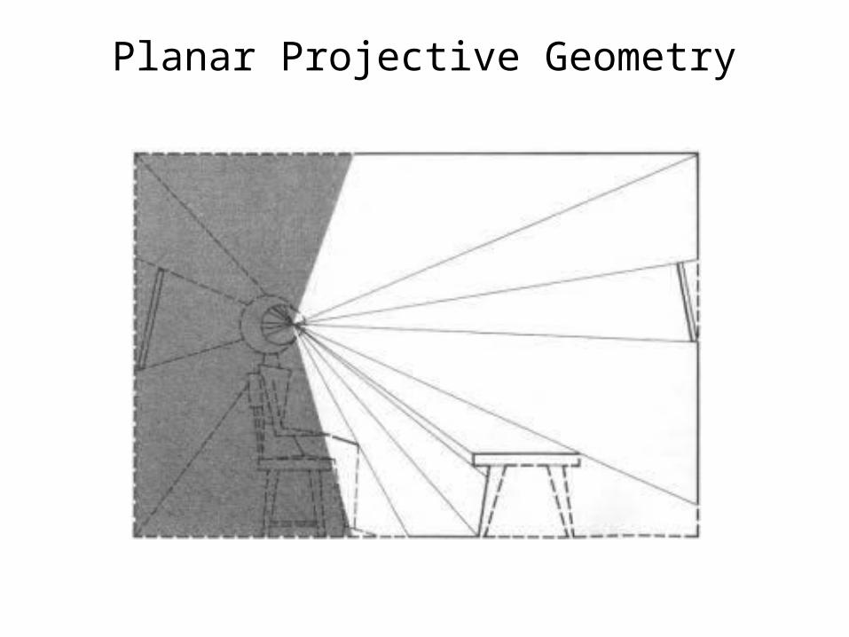
Planar Projective Geometry
WHAT IS SEEN AT THIS MOMENTFROM THIS POSITION
DOES NOT COMPRISE WHAT IS SEEN
• The environment seen-at-this-moment does not constitute the environment that is seen.
• Neither does the environment seen-from-this-point constitute the environment that is seen.
• The seen-now and the seen-from-here specify the self, not the environment.
• Consider them separately.

The surfaces viewed now from here by an observer seated in a room.
T H E PROBLEM OF P U B L I C KNOWLEDGE
• It is true that there is a different array for each point of observation and that different observers must occupy different points at any one time.
• But observers move, and the same path may be traveled by any observer. If a set of observers move around, the same invariants under optical transformations and occlusions will be available to all.
• To the extent that the invariants are detected, all observers will perceive the same world. Each will also be aware that his or her place in the world is different here and now from that of any other.
THE PUZZLE OF EGO CENTRIC AWARENESS
• The sensation-based theories of perception assume that the perspective appearances of the world are all that a newborn infant is given.
• They are the data for perception. Hence, the young child is necessarily egocentric, and cognitive development is a matter of progressing from subjective sensations to objective perceptions.
• The child's ego encompasses the world, and at the same time she is supposed to be confined to the awareness of her fleeting sensations.
• But there is a reason to be suspicious of all these speculations.

Planar dynamics • The fact of an environment that is mainly rigid will become
evident when we talk about the geometry of the environment and its transformations.
• Planar dynamics are linked to geometrical constructions.• Twists are represented as points in the plane, and wrenches
as lines.• Representing the kinematics and dynamics graphically
requires ways of visualizing the addition of two or more points and the addition of two or more lines.
• Forces cause acceleration and acceleration requires forces is viewed as a way of mapping points to lines and vice versa.
S U M M ARY O F T H E T H E O R Y OF Information P I C K U P
• According to the theory being proposed, perceiving is a registering of certain definite dimensions of invariance in the stimulus flux together with definite parameters of disturbance.
• The invariants are invariants of structure, and the disturbances are disturbances of structure. The structure, for perception, is that of the ambient array.
• The fact is that, although one can become aware of the seen-now and the seen from-here if one takes the attitude of introspection, what one perceives is an environment that surrounds one, that is everywhere equally clear, that is in-the-round or solid, and that is all-of-a- piece.

Planar Twists
• In mechanics, planar motion of rigid body is generally a rotation about a particular point called a pole. When this pole is located at infinity the motion is a pure translation.
• This projection ignores any linear velocity out of the plane and all angular velocities along the plane.
• The easiest way to perform this projection is through the planar subspace matrix.
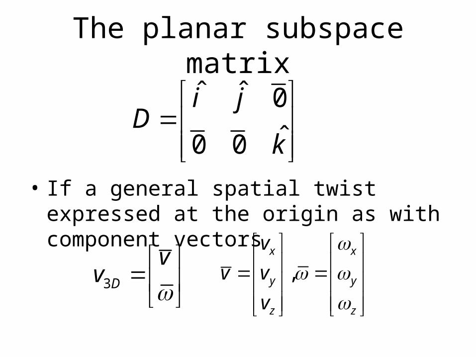
The planar subspace matrix
• If a general spatial twist expressed at the origin as with component vectors
ˆ ˆ 0ˆ0 0
i jD
k
3D
vv
,x x
y y
z z
vv v
v
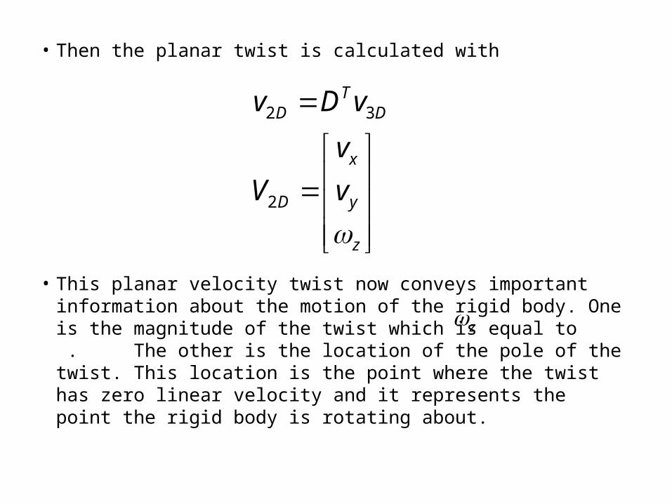
• Then the planar twist is calculated with
• This planar velocity twist now conveys important information about the motion of the rigid body. One is the magnitude of the twist which is equal to . The other is the location of the pole of the twist. This location is the point where the twist has zero linear velocity and it represents the point the rigid body is rotating about.
2 3
2
TD D
x
D y
z
v D v
vV v
z
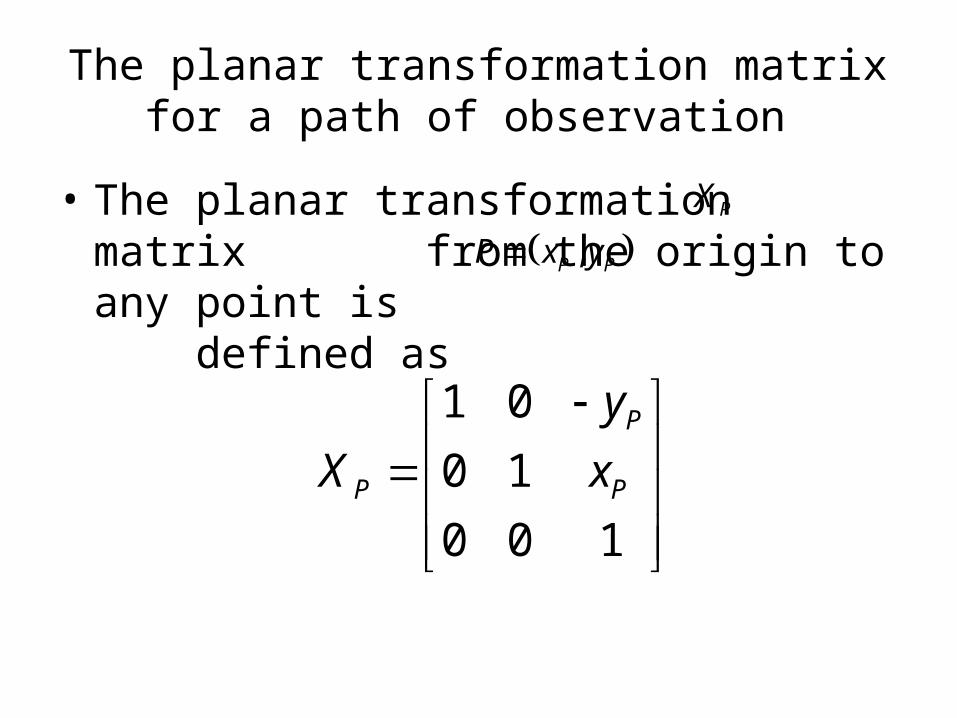
The planar transformation matrix for a path of observation
• The planar transformation matrix from the origin to any point is defined as
PX ,P PP x y
1 00 10 0 1
P
P P
yX x
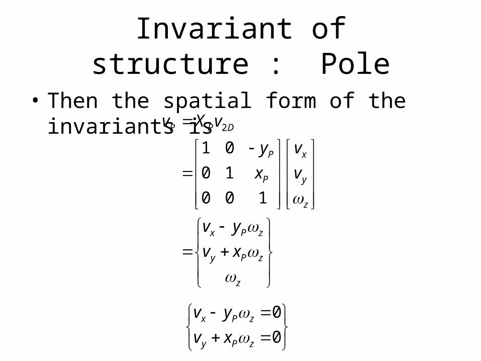
Invariant of structure : Pole
• Then the spatial form of the invariants is
2
1 00 10 0 1
P P D
P x
P y
z
x P z
y P z
z
v X vy vx v
v yv x
00
x P z
y P z
v yv x

The pole P
• Yielding the solution for the pole P as
• This point P (invariant) and the magnitude (disturbance) completely describe a planar rigid body motion. Since twists describe rigid body motion, planar twists must contain information about point P.
, ,y xP P
z z
v vx y
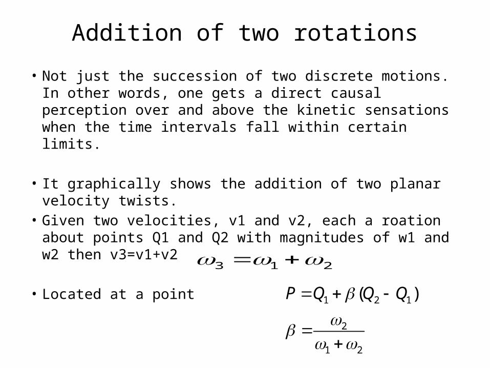
Addition of two rotations
• Not just the succession of two discrete motions. In other words, one gets a direct causal perception over and above the kinetic sensations when the time intervals fall within certain limits.
• It graphically shows the addition of two planar velocity twists.
• Given two velocities, v1 and v2, each a roation about points Q1 and Q2 with magnitudes of w1 and w2 then v3=v1+v2
• Located at a point
3 1 2
1 2 1
2
1 2
( )P Q Q Q

The two pure rotations add up to a pure rotation
In planar dynamics the relative strength of each rotation is proportional to the proximity of the resulting rotation.

Lever rule in statics
A simply supported beam
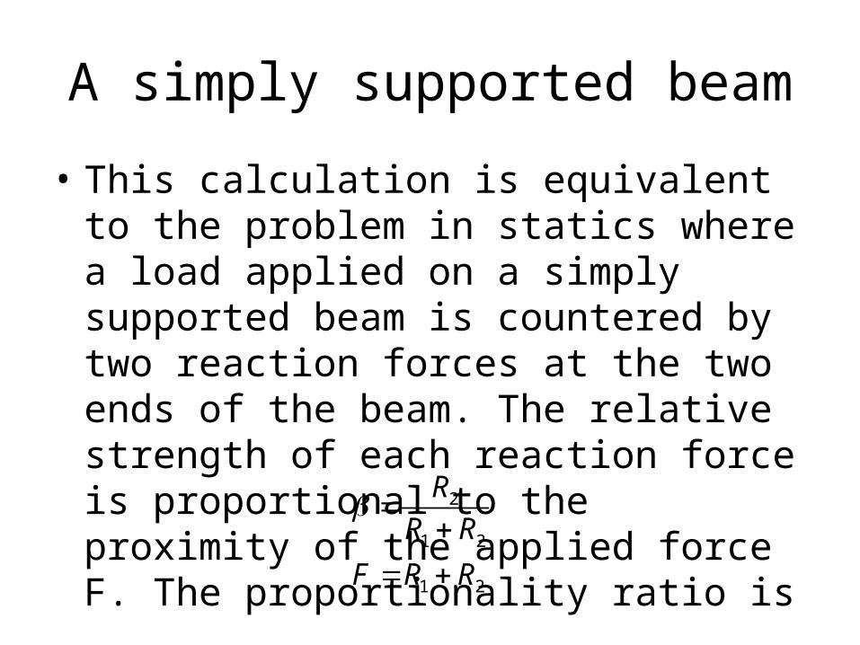
• This calculation is equivalent to the problem in statics where a load applied on a simply supported beam is countered by two reaction forces at the two ends of the beam. The relative strength of each reaction force is proportional to the proximity of the applied force F. The proportionality ratio is
2
1 2
1 2
RR R
F R R
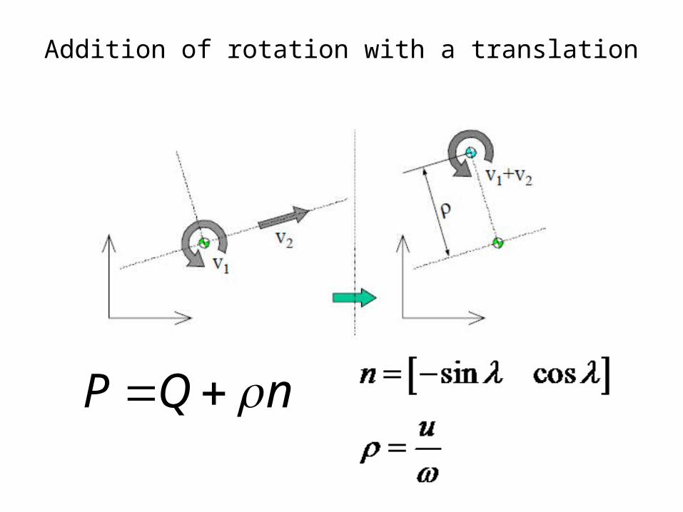
Addition of rotation with a translation
P Q n

Two translations
• It is not possible for the result to be a translation in the case of the addition of a rotation to a translation.
• The only special case is when both v1 and v2 are translations.
• Such a case results in a translation along the direction of the vector sum of the two translations.
Planar wrenches
• In planar rigid body dynamics loads represent the application of a net force along a particular line called a polar.
• A pure couple represents a special case when the polar moves to infinity. Normally the polar line represents the collection of points with zero net moment about them.
• This projection is also performed by the projection matrix D since it ignores all forces out of the plane, and all moments along the plane.

A general spatial wrench • If a general spatial wrench expressed on the
origin is
• Then the planar wrench is calculated with
3
,
D
x x
y y
z z
ff
ff f
f
2 3
2
TD D
x
D y
z
f D f
ff f
The easiest way to perform this projection is through the planar subspace matrix.
ˆ ˆ 0
ˆ0 0
i jD
k
Disturbance of structure
• These planar wrench conveys important information about the loading of the rigid body. One is the magnitude of the net force which is equal to
2 2x yF f f
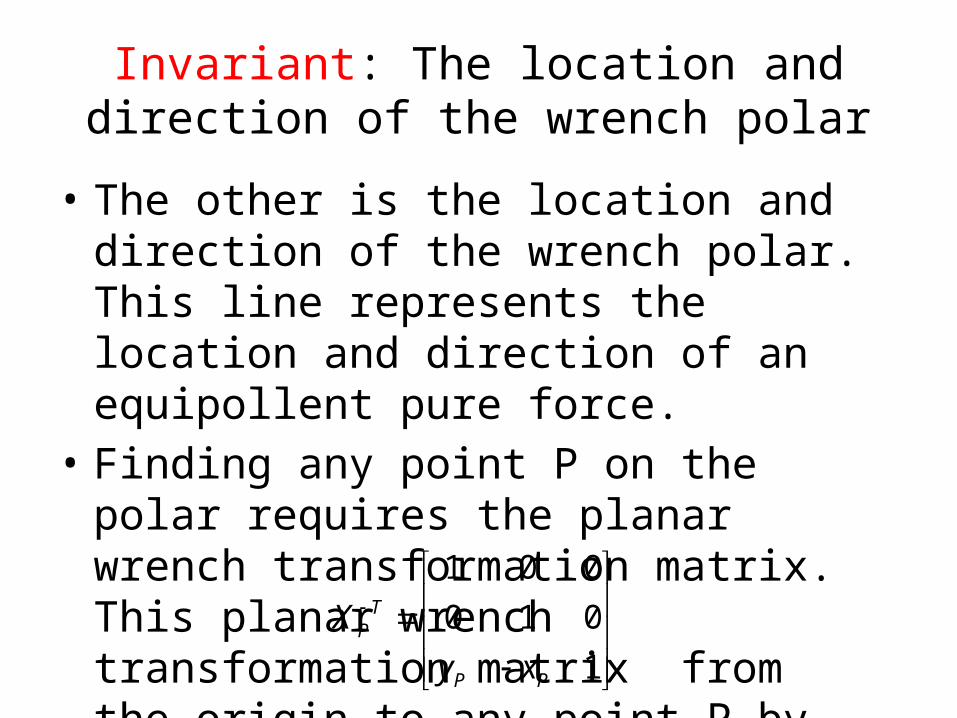
Invariant: The location and direction of the wrench polar
• The other is the location and direction of the wrench polar. This line represents the location and direction of an equipollent pure force.
• Finding any point P on the polar requires the planar wrench transformation matrix. This planar wrench transformation matrix from the origin to any point P by component is
1 0 00 1 0
1
TP
P P
Xy x
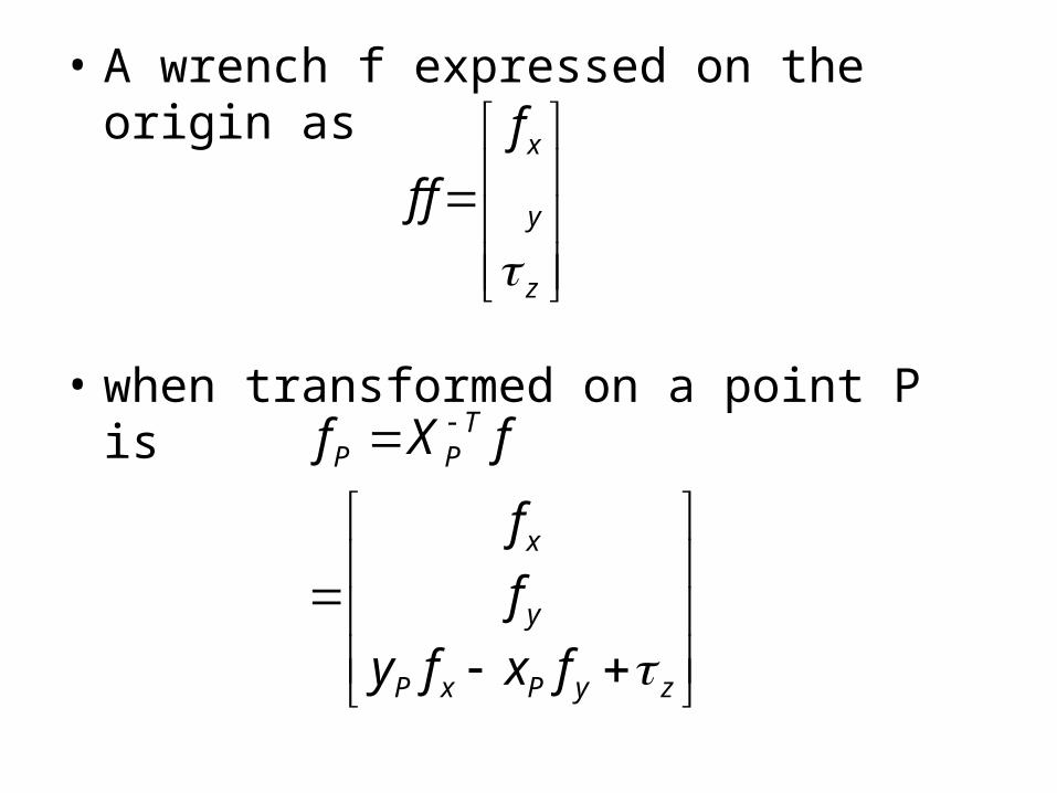
• A wrench f expressed on the origin as
• when transformed on a point P is
x
y
z
ff f
TP P
x
y
P x P y z
f X f
ff
y f x f
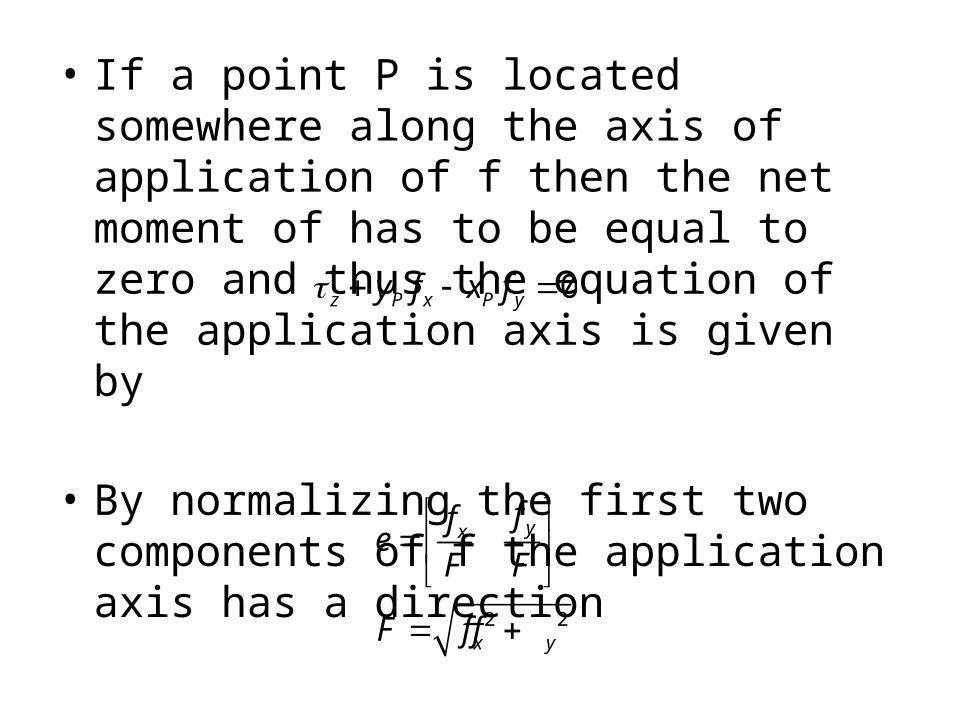
• If a point P is located somewhere along the axis of application of f then the net moment of has to be equal to zero and thus the equation of the application axis is given by
• By normalizing the first two components of f the application axis has a direction
0z P x P yy f x f
2 2
yx
x y
ffeF F
F f f
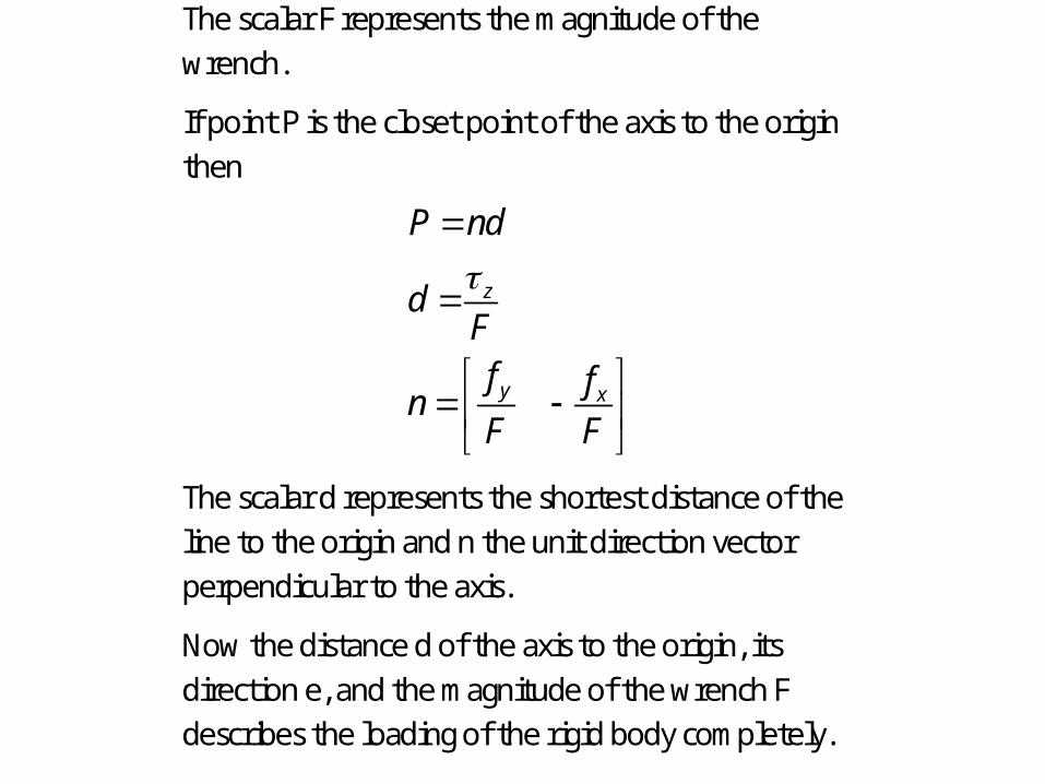
The scalar F represents the magnitude of the wrench.
If point P is the closet point of the axis to the origin then
z
y x
P nd
dFf fnF F
The scalar d represents the shortest distance of the line to the origin and n the unit direction vector perpendicular to the axis.
Now the distance d of the axis to the origin, its direction e, and the magnitude of the wrench F describes the loading of the rigid body completely.
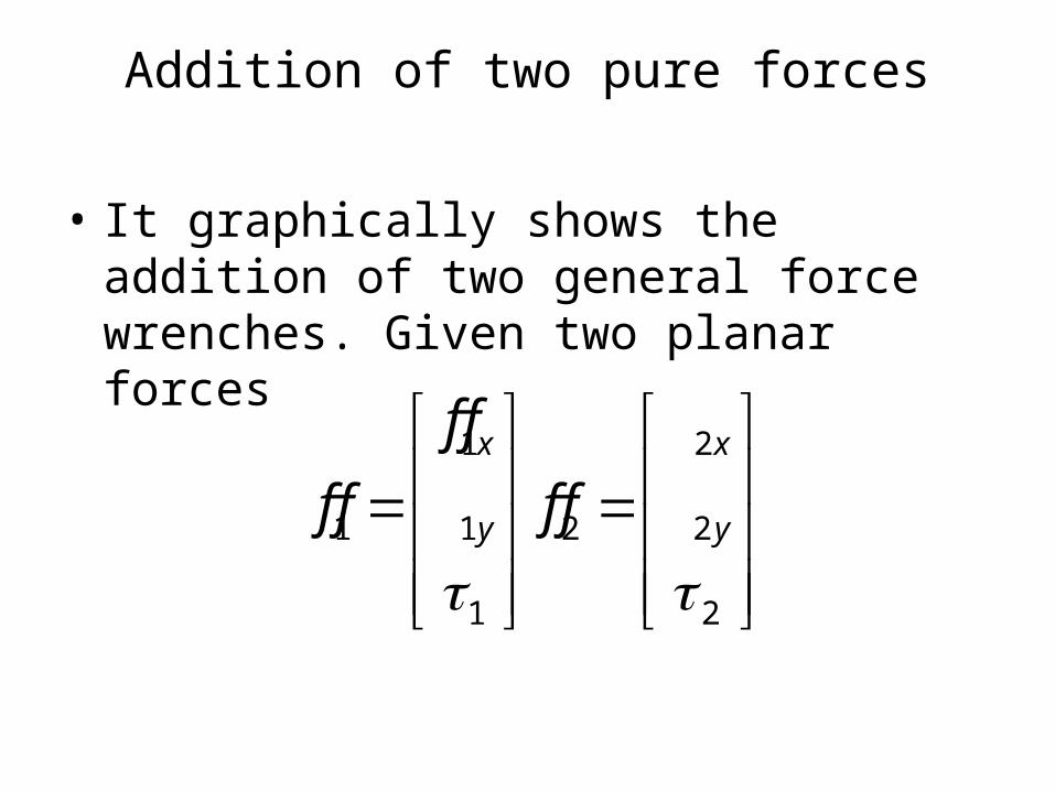
Addition of two pure forces
• It graphically shows the addition of two general force wrenches. Given two planar forces
1 2
1 1 2 2
1 2
x x
y y
f ff f f f
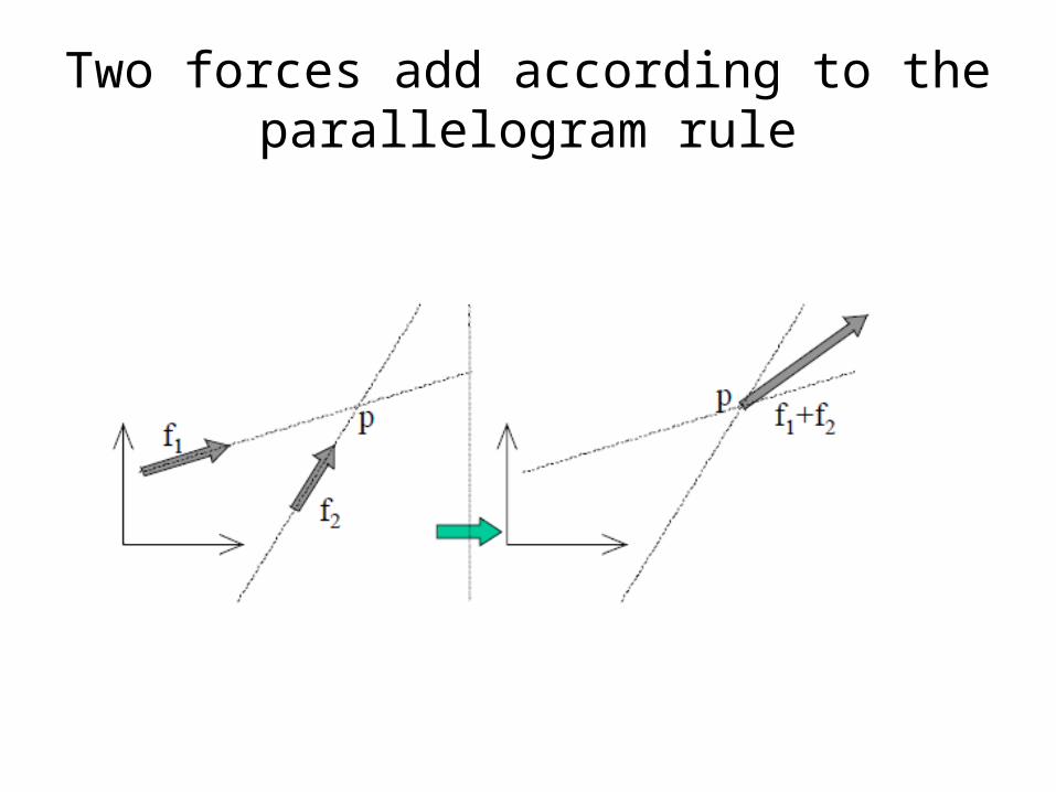
Two forces add according to the parallelogram rule
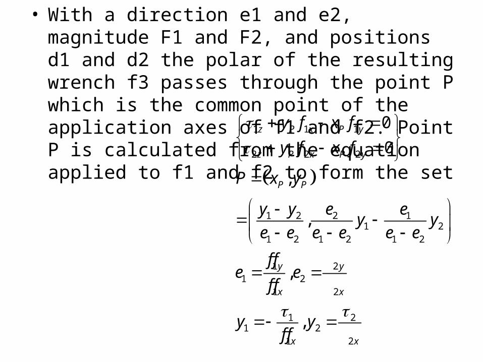
• With a direction e1 and e2, magnitude F1 and F2, and positions d1 and d2 the polar of the resulting wrench f3 passes through the point P which is the common point of the application axes of f1 and f2. Point P is calculated from the equation applied to f1 and f2 to form the set
1 1 1
2 2 2
1 2 2 11 2
1 2 1 2 1 2
1 21 2
1 2
1 21 2
1 2
00
,
,
,
,
z P x P y
z P x P y
P P
y y
x x
x x
y f x fy f x f
P x y
y y e ey ye e e e e ef f
e ef f
y yf f

The direction of the pole
• The direction of the pole is
3 1 2 1 23
2 23 1 2 1 2
1
( ) ( )
x x y y
x x y y
e f f f fF
F f f f f
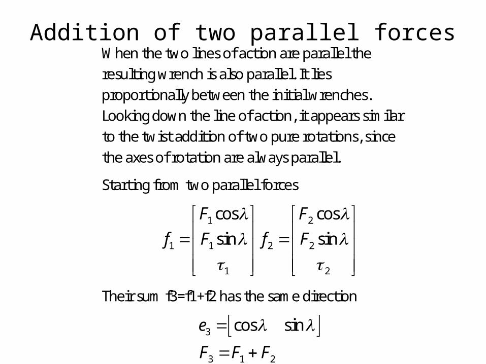
Addition of two parallel forcesWhen the two lines of action are parallel the resulting wrench is also parallel. It lies proportionally between the initial wrenches. Looking down the line of action, it appears similar to the twist addition of two pure rotations, since the axes of rotation are always parallel.
Starting from two parallel forces
1 2
1 1 2 2
1 2
cos cossin sin
F Ff F f F
Their sum f3=f1+f2 has the same direction
3
3 1 2
cos sine
F F F
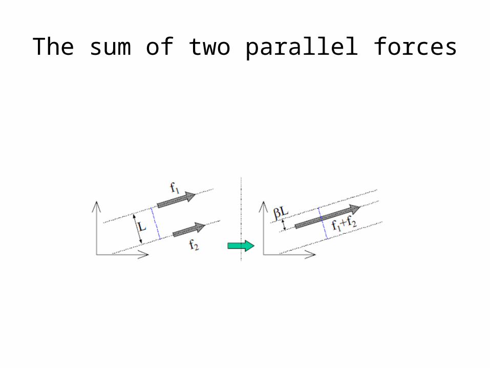
The sum of two parallel forces
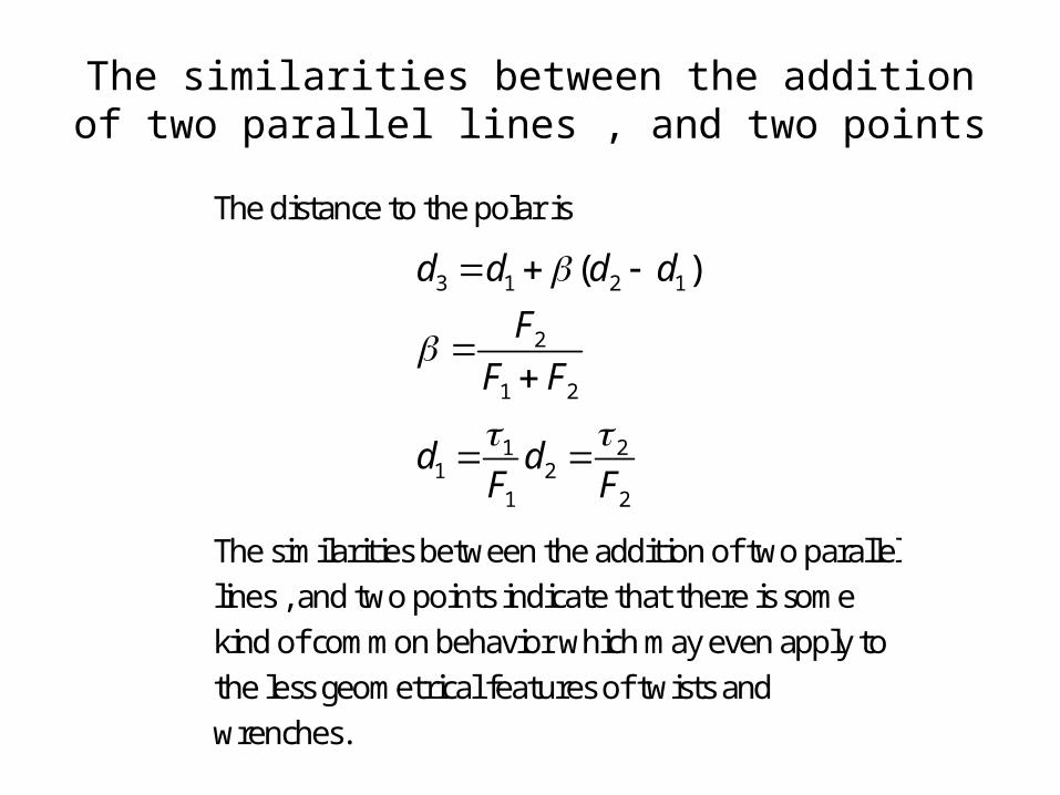
The similarities between the addition of two parallel lines , and two points
The distance to the polar is
3 1 2 1
2
1 2
1 21 2
1 2
( )d d d dF
F F
d dF F
The similarities between the addition of two parallel lines , and two points indicate that there is some kind of common behavior which may even apply to the less geometrical features of twists and wrenches.

Addition of a force and a moment
• Given a pure force f1 and a pure couple f2 the sum f3=f1+f2 is a pure force. It is parallel to f1 at a perpendicular distance
• Where F is the magnitude of force f1 and tau the magnitude of the pure couple f2. The magnitude of f3 is equal to F.
F

A force and a couple create a parallel force