DOC002€¦ · CATEGORIA IV . Title: DOC002.pdf Author: Utente Created Date: 2/7/2015 4:01:44 PM
00
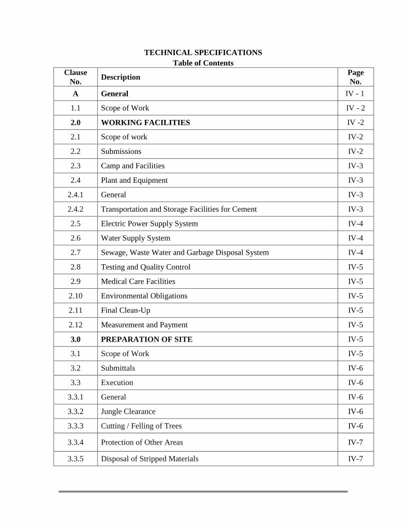
PREPARATION OF WATER AND WASTEWATER MASTER
PLAN FOR DAMPHU, TSIRANG, BHUTAN
DEPARTMENT OF ENGINEERING SERVICES,
MINISTRY OF WORKS & HUMAN SETTLEMENT
ROYAL GOVERNMENT OF BHUTAN
WAPCOS LIMITED 76 – C, Institutional Area, Sector – 18
Gurgaon – 122015 (Haryana), India
Phone: +91-124-2342576, Fax: +91-124-2349187
E-mail: [email protected]
In Association with
M/s Himalaya Engineering & Management Consultancy P.O box no 342, Thimphu. Tel:02 32 73 45.Fax:02 33 46 07.
Email:[email protected]
TECHNICAL SPECIFICATIONS
SEPTEMBER, 2016
TECHNICAL SPECIFICATIONS
Table of Contents
Clause
No. Description
Page
No.
2.4.1 General IV-3
2.4.2 Transportation and Storage Facilities for Cement IV-3
2.5 Electric Power Supply System IV-4
2.6 Water Supply System IV-4
2.7 Sewage, Waste Water and Garbage Disposal System IV-4
2.8 Testing and Quality Control IV-5
2.9 Medical Care Facilities IV-5
2.10 Environmental Obligations IV-5
2.11 Final Clean-Up IV-5
2.12 Measurement and Payment IV-5
3.0 PREPARATION OF SITE IV-5
3.1 Scope of Work IV-5
3.2 Submittals IV-6
3.3 Execution IV-6
3.3.1 General IV-6
3.3.2 Jungle Clearance IV-6
3.3.3 Cutting / Felling of Trees IV-6
3.3.4 Protection of Other Areas IV-7
3.3.5 Disposal of Stripped Materials IV-7
A General IV - 1
1.1 Scope of Work IV - 2
2.0 WORKING FACILITIES IV -2
2.1 Scope of work IV-2
2.2 Submissions IV-2
2.3 Camp and Facilities IV-3
2.4 Plant and Equipment IV-3

3.3.6 Auxiliary Works IV-8
3.4 Measurement and Payment IV-8
3.4.1 Measurement IV-8
3.4.2 Payment IV-8
4.0 EARTH WORKS IV-9
4.1 Scope of Work IV-9
4.2 General Requirements
IV-9
4.3 Specifications and Standards IV-11
A EXCAVATION IV-11
4.4 Classification of Excavation IV-11
4.4.1 Excavation in Soil IV-11
4.4.2 Excavation in Rock IV-11
4.5 Blasting IV-12
4.6 Disposal and Stockpiling of Materials from Excavation IV-12
4.7 Excavation Tolerances IV-12
4.8 Dewatering IV-13
4.9 Slides IV-13
4.10 Slopes Support and Protection IV-13
4.11 Measurement and Payment IV-13
4.11.1 Measurement IV-13
4.11.2 Payment IV-14
4.11.2.1 General IV-14
4.11.2.2 Payment for Over-excavation IV-14
4.11.2.3 Payment for Dewatering IV-14
B FILLING IV-15
4.12 Definition of Fill IV-15
4.13 Fill Material IV-15
4.14 Execution of Filling IV-15
4.15 Measurement and Payment IV-16
4.15.1 Measurement IV-16
4.15.2 Payment IV-16
4.16 Sand filling
IV-16
5.0 MASONRY WORKS
IV-16
5.1 Scope of Works IV-16
5.2 General Requirements IV-17
5.3 Submission IV-17
5.4 Classification of Masonry IV-17
5.5 Execution IV-18
5.5.1 General IV-18
5.5.2 Mixing, Transporting and Placing IV-18
5.6 Brick Masonry/Concrete Block Brick Masonry IV-19
5.6.1 General Physical Characteristic of Bricks IV-19
5.6.2 Physical requirement of bricks IV-19
5.6.3 General Physical Characteristic of Concrete Block Brick IV-19
5.6.4 Laying IV-21
5.6.5 Joints
IV-21
5.6.6 Curing IV-21
5.6.7 Scaffolding IV-21
5.6.8 Measurement IV-21
5.6.9 Rate IV-22
5.7 Random Rubble Masonry IV-22
5.7.1 General IV-22
5.7.2 Scaffolding IV-22
5.7.3 Curing IV-22
5.7.4 Protection IV-22
5.7.5 Measurements IV-22
5.7.6 Rate IV-22

5.7.7 Water Proofing Materials in Cement Mortar. IV-22
5.7.8 General IV-22
5.7.9 Measurement IV-23
5.7.10 Rate IV-23
5.7.11 Hand packed stone filling or soling with stone IV-23
5.7.12 Measurement IV-23
5.7.13 Rate IV-23
6.0 CONCRETE WORKS IV-23
6.1 Scope of Work IV-23
6.2 Definitions IV-23
6.3 Submission
IV-24
6.4 Materials IV-24
6.5 Execution of Concrete Works IV-24
6.5.1 General Requirement IV-24
6.5.2 Execution of Plain Concrete Works (PCC) IV-25
6.5.2.1 Mixing of Concrete IV-25
6.5.2.2 Consistency and Slump of Concrete IV-26
6.5.2.3 Strength of Concrete IV-26
6.5.2.4 Placing of Concrete IV-27
6.5.3 Execution of Reinforced Concrete Works(RCC) IV-27
6.5.3.1 General Requirement IV-27
6.5.3.2 Fabrication of Reinforcements IV-27
6.5.3.3 Consistency of RCC IV-29
6.5.4 Form Work IV-29
6.6 Measurement and Payment IV-31
6.6.1 Measurements and Payment for Concrete IV-31
6.6.1.1 Measurements for Concrete IV-31
6.6.1.2 Payment for Concrete IV-32
6.6.2 Measurements and Payment for Formwork IV-32
6.6.2.1 Measurement for Formwork IV-32
6.6.2.2 Payment for Form works IV-32
6.6.3 Measurement and Payment for Reinforcements IV-32
6.6.3.1 Measurement for Reinforcement IV-32
6.6.3.2 Payment for Reinforcements IV-33
B Water Supply & Sewerage IV-33
1.0 RCC PIPE IV-33
1.1 Trenches IV-33
1.2 Laying IV-34
1.3 Socket and spigot joint
IV-35
1.4 Testing of joints IV-35
1.5 Refilling IV-36
1.6 Measurements IV-36
1.7 Rate IV-36
2.0 GI & HDPE pipe and fittings IV-36
2.1 GI Pipes & Pipe Fittings IV-36
2.1.1 GI Pipe IV-36
2.1.2 GI Union IV-38
2.2 HDPE Pipe & Pipe fittings IV-38
2.2.1 HDPE Pipe IV-38
2.3 Laying of Pipes IV-40
2.4 Testing the Joints
IV-40
2.5 Measurements IV-40
2.6 Rate IV-41
3.0 Ductile iron Pipe & fittings
IV-41
3.1 Excavation and Preparation of Trenches
IV-41

3.2 Back filling IV-41
3.2.1 Back fill Material IV-42
3.2.2 Back fill sand IV-42
3.2.3 Back – filling gravel IV-42
3.3 Laying of pipes IV-42
3.3.1 Laying Underground
IV-42
3.3.2 Laying above ground IV-43
3.3.3 Pipe support IV-43
3.3.4 Cutting of pipes IV-43
3.3.4.1 By Hacksaw IV-43
3.3.4.2 By Manually Operated Wheel Cutter
IV-43
3.3.4.3 By Pipe Cutting Machine IV-43
3.3.4.4 End Preparation of Cut Pipes for Jointing
IV-43
3.4 Wrapping
IV-43
3.5 Anchorage IV-44
3.6 Joints
IV-44
3.7 Transportation Handling and Inspection IV-44
3.7.1 General IV-44
3.7.2 Transportation IV-44
3.8 Offloading IV-44
3.9 Stacking IV-45
3.10 HYDRAULIC TESTING IV-45
3.10.1 General IV-45
3.10.2 Test pressure IV-45
3.10.3 Methods employed for finding leaks IV-46
4.0 FLUSHING AND DISINFECTION OF MAINS BEFORE
COMMISSIONING IV-47
4.1 Distribution System Chlorination of New Mains IV-47
4.2 Continuous Feed
IV-48
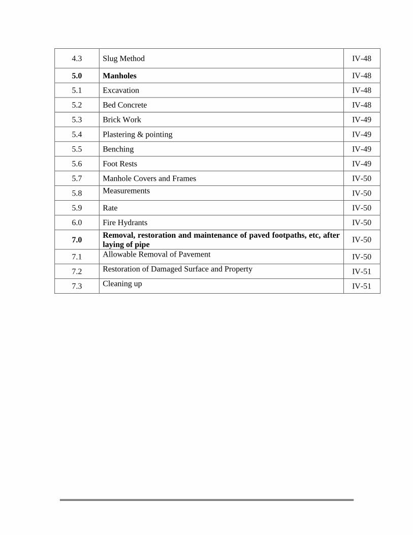
4.3 Slug Method IV-48
5.0 Manholes IV-48
5.1 Excavation IV-48
5.2 Bed Concrete IV-48
5.3 Brick Work IV-49
5.4 Plastering & pointing IV-49
5.5 Benching IV-49
5.6 Foot Rests IV-49
5.7 Manhole Covers and Frames IV-50
5.8 Measurements
IV-50
5.9 Rate IV-50
6.0 Fire Hydrants IV-50
7.0 Removal, restoration and maintenance of paved footpaths, etc, after
laying of pipe IV-50
7.1 Allowable Removal of Pavement
IV-50
7.2 Restoration of Damaged Surface and Property
IV-51
7.3 Cleaning up
IV-51
IV-1
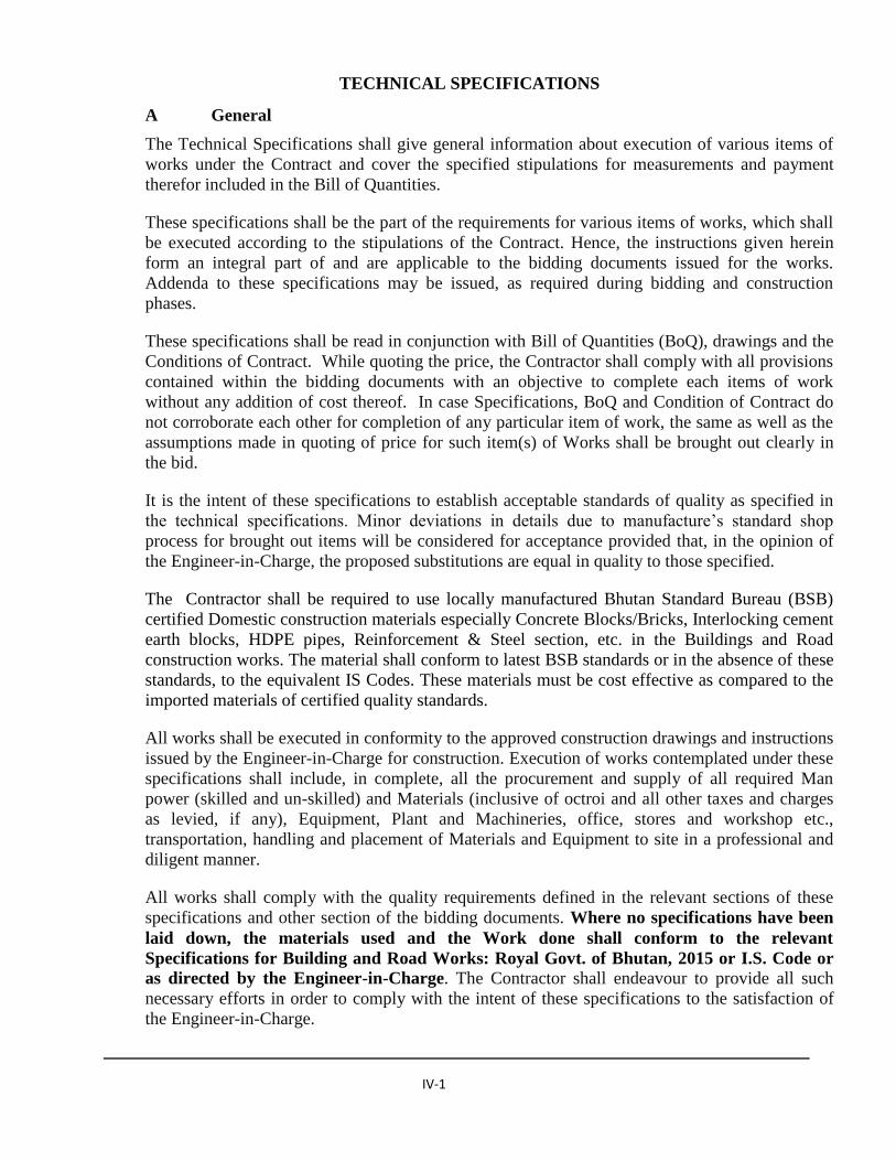
TECHNICAL SPECIFICATIONS
A General
The Technical Specifications shall give general information about execution of various items of
works under the Contract and cover the specified stipulations for measurements and payment
therefor included in the Bill of Quantities.
These specifications shall be the part of the requirements for various items of works, which shall
be executed according to the stipulations of the Contract. Hence, the instructions given herein
form an integral part of and are applicable to the bidding documents issued for the works.
Addenda to these specifications may be issued, as required during bidding and construction
phases.
These specifications shall be read in conjunction with Bill of Quantities (BoQ), drawings and the
Conditions of Contract. While quoting the price, the Contractor shall comply with all provisions
contained within the bidding documents with an objective to complete each items of work
without any addition of cost thereof. In case Specifications, BoQ and Condition of Contract do
not corroborate each other for completion of any particular item of work, the same as well as the
assumptions made in quoting of price for such item(s) of Works shall be brought out clearly in
the bid.
It is the intent of these specifications to establish acceptable standards of quality as specified in
the technical specifications. Minor deviations in details due to manufacture’s standard shop
process for brought out items will be considered for acceptance provided that, in the opinion of
the Engineer-in-Charge, the proposed substitutions are equal in quality to those specified.
The Contractor shall be required to use locally manufactured Bhutan Standard Bureau (BSB)
certified Domestic construction materials especially Concrete Blocks/Bricks, Interlocking cement
earth blocks, HDPE pipes, Reinforcement & Steel section, etc. in the Buildings and Road
construction works. The material shall conform to latest BSB standards or in the absence of these
standards, to the equivalent IS Codes. These materials must be cost effective as compared to the
imported materials of certified quality standards.
All works shall be executed in conformity to the approved construction drawings and instructions
issued by the Engineer-in-Charge for construction. Execution of works contemplated under these
specifications shall include, in complete, all the procurement and supply of all required Man
power (skilled and un-skilled) and Materials (inclusive of octroi and all other taxes and charges
as levied, if any), Equipment, Plant and Machineries, office, stores and workshop etc.,
transportation, handling and placement of Materials and Equipment to site in a professional and
diligent manner.
All works shall comply with the quality requirements defined in the relevant sections of these
specifications and other section of the bidding documents. Where no specifications have been
laid down, the materials used and the Work done shall conform to the relevant
Specifications for Building and Road Works: Royal Govt. of Bhutan, 2015 or I.S. Code or
as directed by the Engineer-in-Charge. The Contractor shall endeavour to provide all such
necessary efforts in order to comply with the intent of these specifications to the satisfaction of
the Engineer-in-Charge.

IV-2
1.1 Scope of Work
The broad scope of works in general, shall be ‘Construction of -----------------------------------------
--------’ which shall include, but not limited to the following:
i. Setting out survey, clearing and grubbing, excavation in soil and rock, backfilling, plain
concrete, plum concrete, and reinforced concrete works, brick & stone masonry works,
steel roof truss, colour coated galvanized sheet roofing, wood & aluminium works,
plastering, painting, water supply and sanitation works, Bhutanese architectural works,
protection & drainage works, electrical works, laying of RCC, DI, HDPE & GI
pipelines, fixing of fixtures, drainage, Sub grade excavation in all types of soils,
supplying/collection and stacking of stone aggregate, WBM, Granular Sub-Base (GSB),
Wet Mix Macadam (WMM), Dense Bituminous Macadam (DBM), Asphalt/Bituminous
concrete surfacing, construction of lined drain works and other miscellaneous works to
fulfill the architectural, structural and functional requirements but not limited to the
major item of works, as per the approved design drawings and specifications and/or as
directed by the Engineer-in-Charge.
ii. The above work shall also include:
(a) Electrical, Sanitary and Plumbing Works with all fittings and fixtures,
(b) Misc. works, if any
2.0 Working Facilities
2.1 Scope of work
The scope of works under this clause to design, provide, erect, operate and maintain all the
working facilities as would be necessary for execution of the Works within the specified time
schedule, but not necessarily limited to the following:
- Camp and Facilities
- Plant and Equipment
- Electric Power Supply System
- Water Supply System
- Sewage & Waste Water and Garbage Disposal System
- Temporary Access and Construction Roads
Working Facilities shall be subject to the Engineer-in-Charge’s approval. The Contractor shall
comply with all applicable laws, regulations, and ordinances relating to the construction and
operation of the working facilities in Bhutan.
2.2 Submissions
The Contractor shall submit basic plans of Working Facilities along with his bid. He shall attach
to his bid documents drawings and operating descriptions for his proposed working facilities. At
least 15 days prior to commencing the work, the Contractor shall submit to the Engineer-in-
Charge for approval the drawings of layout and details of Working Facilities.
Should the Engineer-in-Charge determine that the details of working facilities furnished does
not meet all requirements, the deficiencies shall be made good by the Contractor before
IV-3
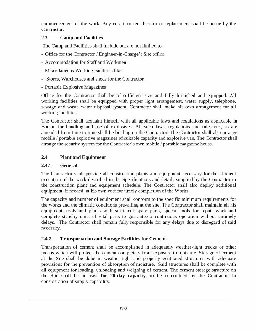
commencement of the work. Any cost incurred therefor or replacement shall be borne by the
Contractor.
2.3 Camp and Facilities
The Camp and Facilities shall include but are not limited to
- Office for the Contractor / Engineer-in-Charge’s Site office
- Accommodation for Staff and Workmen
- Miscellaneous Working Facilities like:
- Stores, Warehouses and sheds for the Contractor
- Portable Explosive Magazines
Office for the Contractor shall be of sufficient size and fully furnished and equipped. All
working facilities shall be equipped with proper light arrangement, water supply, telephone,
sewage and waste water disposal system. Contractor shall make his own arrangement for all
working facilities.
The Contractor shall acquaint himself with all applicable laws and regulations as applicable in
Bhutan for handling and use of explosives. All such laws, regulations and rules etc., as are
amended from time to time shall be binding on the Contractor. The Contractor shall also arrange
mobile / portable explosive magazines of suitable capacity and explosive van. The Contractor shall
arrange the security system for the Contractor’s own mobile / portable magazine house.
2.4 Plant and Equipment
2.4.1 General
The Contractor shall provide all construction plants and equipment necessary for the efficient
execution of the work described in the Specifications and details supplied by the Contractor in
the construction plant and equipment schedule. The Contractor shall also deploy additional
equipment, if needed, at his own cost for timely completion of the Works.
The capacity and number of equipment shall conform to the specific minimum requirements for
the works and the climatic conditions prevailing at the site. The Contractor shall maintain all his
equipment, tools and plants with sufficient spare parts, special tools for repair work and
complete standby units of vital parts to guarantee a continuous operation without untimely
delays. The Contractor shall remain fully responsible for any delays due to disregard of said
necessity.
2.4.2 Transportation and Storage Facilities for Cement
Transportation of cement shall be accomplished in adequately weather-tight trucks or other
means which will protect the cement completely from exposure to moisture. Storage of cement
at the Site shall be done in weather-tight and properly ventilated structures with adequate
provisions for the prevention of absorption of moisture. Said structures shall be complete with
all equipment for loading, unloading and weighing of cement. The cement storage structure on
the Site shall be at least for 20-day capacity, to be determined by the Contractor in
consideration of supply capability.

IV-4
2.5 Electric Power Supply System
The Contractor shall make all arrangement for distribution within his working area. The electric
energy consumed by the Contractor shall be measured by a suitable Energy meter installed at the
supply point and the cost thereof shall be paid by the Contractor at the prevailing rates.
The power supply to the construction sites, camps and the entire project area shall be designed
for continuous operation, 24 hours a day, with sufficient capacity to satisfy peak and emergency
demands.
The Contractor shall also furnish, install and maintain the electrical distribution system to the
Engineer-in-Charge’s site office.
2.6 Water Supply System
The Contractor shall be fully responsible for the arrangement of necessary facilities for water
supply. The Contractor shall design, construct, equip, operate and maintain two separate water
installations at the Site necessary for the adequate supply of:
a) Raw water: for general construction use, treated to the extent necessary to meet
specified requirements (e.g. for concrete),
b) Potable water: for supply to all buildings and plants requiring high quality water
meeting relevant requirements for drinking water.
The Contractor shall furnish, install, operate and maintain all pumps, piping, fittings, valves,
storage tanks for the water supply and distribution systems, adequate in quantity and pressure.
Raw water shall be used for construction purposes only if of adequate quality. There shall be no
cross connections of any kind between the raw and potable water supply systems. Only potable
water shall be piped into buildings.
2.7 Sewage, Waste Water and Garbage Disposal System
The Contractor shall design, construct, equip, operate and maintain all the installation necessary
to properly collect, treat and dispose of sewage from the camp office and other construction
facilities. The Contractor shall not, under any circumstances, discharge sewage or contaminated
water into natural streams or any open areas. Treatment and disposal of sewage shall be
performed in accordance with the current related standards and laws in force in Bhutan and
always subject to the Engineer-in-Charge’s approval. The drainage systems shall be designed
taking into account the rainfall /snowfall rate in the area and the disposal of rainwater/snow shall
be accomplished in such a way that no erosion problems are caused which may alter the stability
of the soil.
The Contractor shall provide necessary arrangements for disposal of waste and garbage disposal.
The areas surrounding camps, offices, job facilities and the work sites shall be kept clean and free
of refuse at all times. No waste shall be dumped in areas other than those approved by the
Engineer-in-Charge for waste disposal. No waste of any kind shall be deposited in any
watercourses. The Contractor shall observe the norms prescribed by the Government of Bhutan
for keeping all areas clean.

IV-5
2.8 Testing and Quality Control
The Contractor shall collect the samples as specified or as directed by the Engineer-in-Charge,
carryout the relevant test as approved by the Engineer-in-Charge and submit the test reports to
the Engineer-in-Charge in time. All tests will be made according to the approved standards.
2.9 Medical Care Facilities
In the event of illness of an epidemic nature breaking out, the Contractor shall carry out and
comply with all orders, arrangements or regulations, which may be issued by the Government or
local authorities. Basic Medical facilities are available at Samtse. The Contractor shall provide
and maintain at least one first aid facilities at the work site.
2.10 Environmental Obligations
The Contractor shall, during the whole period of the Works comply fully with all applicable laws
and regulations relating to environmental protection, mitigating measures for reducing
environmental impacts and remedial works on completion of the Works. This obligation shall
extend to the construction sites themselves, all the Contractor’s site installations, and all quarries,
borrow areas and tips.
2.11 Final Clean-Up
Upon the Completion of Works, or when any plant has completed its functions, the Contractor
shall dismantle and demobilize all temporary facilities and remove all refuse, debris,
objectionable material, and fill, grade and dress all excavated areas in a clean and proper
condition acceptable to the Engineer-in-Charge. All such areas, as far as possible, shall conform
to the natural appearance of the landscape.
2.12 Measurement and Payment
No separate payment for establishing the working facilities shall be made. Cost of all such
working facilities shall be included in the unit price of works. No separate payment shall be
made for complying with any environmental obligations required by applicable laws and
regulations, and all such costs incurred by the Contractor to this end shall be considered as being
included in the Contractor’s Unit Prices.
3.0 PREPARATION OF SITE
3.1 Scope of Work
The Scope of Works under this clause covers preparation of the site of works as required or as
designated by the Engineer-in-Charge for proper execution of various works under the Contract.
The Contractor shall provide all equipment and machinery, skilled and auxiliary personnel and
materials to commensurate with the various tasks and requirements associated with preparation
of the site. He shall also adopt all safety measures of the workmen and others as per requirement
and / or direction of the Engineer-in-Charge. Safety of the workmen and others in all respects
bears the sole responsibility of the Contractor.

IV-6
3.2 Submittals
At least ten (10) days before beginning of the works, the Contractor shall submit to the Engineer-
in-Charge for his approval:
a) Program of works indicating schedule of time and the area to be covered
b) The arrangements, the Contractor intends to adopt to carry out the work.
3.3 Execution
3.3.1 General
Operation for Site preparation shall be strictly limited to the area to be occupied by the
indispensable works unless otherwise directed by the Engineer-in-Charge. Clearing shall be
extended to approximately three (3) meters beyond the limit of the works for permanent
structures. For temporary works, such extension shall be as minimum as required.
During clearing and grubbing the trees and shrubs, pole lines, fences, monuments, pipe lines etc.
within or adjacent to the work site which are not be disturbed shall be protected properly at his
own cost, from injury or damage by the Contractor. In case of Archaeological monuments within
or adjacent to the area, the Contractor shall provide necessary fencing all around as per the
direction of the Engineer-in-Charge and protect the same properly during execution.
Methods, tools and equipment to be adopted for the work shall be such which will not affect the
property to be preserved. Only such methods, tools and equipment as approved by the Engineer-
in-Charge shall be adopted in the work.
3.3.2 Jungle Clearance
Jungle clearance shall comprise of cutting, removing and disposing of all materials such as
vegetation, grass, brushwood, shrubs, stumps and trees and sapling of girth up to 300 mm
measured at height of 1 m above ground level which in the opinion of Engineer-in-Charge are
unsuitable for incorporation in the works, rubbish and other objectionable matters.
The roots of trees and saplings shall be removed to a depth of 600mm below ground level or
140mm below sub-grade level, whichever is lower. Trees and shrubs, etc. within or adjacent to
the area which are not required to be disturbed during jungle clearance shall be properly
protected by the Contractor at his own cost.
No trees shall be cut from outside areas designated unless absolutely warranted and approved by
the Engineer-in-Charge and all trees designated outside the areas shall be protected carefully
from any damage and cleared areas shall be maintained free of vegetable growth during the
progress of the works.
3.3.3 Cutting / Felling of Trees
After clearance of the grass, vegetation, shrubs and bushes, etc, trees having girth of (i) 300mm
to 600mm and (ii) above 600mm (measured at a height of one metre above ground level) shall be
grouped separately and shall be numbered suitably at site. These trees shall be cut after approval

IV-7
of the Engineer-in-Charge. Felling trees shall include taking out roots up to 600 mm below
ground level or 140 mm below sub-grade level whichever is lower.
The trunks and branches of trees shall be cleared of limbs and tops and cut to suitable places as
directed by the Engineer-in-Charge. Wood, branches, twigs of trees and other useful material
shall be the property of Employer. The serviceable materials shall be stacked in the manner as
directed by the Engineer-in-Charge.
All unserviceable materials shall be disposed off as per the directions of the Engineer-in-Charge.
All excavation below ground level arising out of removal trees, stumps, etc. shall be filled with
suitable material in 40cm layers and compacted thoroughly so that the surface at these points
conform to the surrounding area.
3.3.4 Protection of Other Areas
The Contractor shall ensure that trees and other vegetation outside the areas of the permanent
works and the minimal areas required for temporary works including access are protected and
preserved from damage.
Any clearing required by the Contractor for construction of temporary works, and for any other
purpose shall be at the Contractor’s expense and shall not be carried out without the approval of
the Engineer-in-Charge unless otherwise specified.
The Engineer-in-Charge reserves the right to reinstate any damage to vegetation and the surface
of the ground beyond the areas of the Works (including temporary works) at the expense of the
Contractor.
3.3.5 Disposal of Stripped Materials
All useful materials obtained from clearing operations shall be stacked in the manner as directed
by the Engineer-in-Charge. Trunks and branches of trees shall be cleared of limbs and tops and
stacked neatly at places indicated by the Engineer-in-Charge. The materials shall be the property
of the Engineer-in-Charge.
All unserviceable materials which in the opinion of the Engineer-in-Charge cannot be used or
auctioned shall be removed from and disposed off as per the direction of the Engineer-in-Charge.
Care shall be taken to see that unserviceable materials are disposed off in such a manner that
there is no likelihood of getting mixed up with the materials meant for construction.
When materials are to be buried, they shall be disposed off in horizontal layers alternatively with
earth layers and shall be compacted to the maximum extent practicable by routing the haulage
traffic over the area. The maximum height of these spoil materials will be 3 m with slope less
than 4:1 (4 horizontal to 1 vertical) in adequate conditions in regard of safety for the stability of
the deposit. Vegetal matter shall be covered with 1 m of earth material.
Disposal of waste materials by burning will be permitted only at times when conditions are
considered favorable for burning and at locations approved by the Engineer-in-Charge. Materials
to be burnt shall be piled neatly in such a manner and in such locations as to cause the least fire
risk. Burning shall be thorough so that the burnt materials are reduced to ashes. No logs,
branches or charred pieces shall be permitted to remain. The Contractor shall at all times take
special precautions to prevent fire from spreading to areas beyond the limits of the cleared areas
and shall have available at the times suitable equipment and supplied for use in preventing and
suppressing fires. Care shall be taken to see that the burning of such material does not destroy or

IV-8
damage public of private property and adjacent vegetation, and the Contractor shall be fully
responsible for destruction, damage, or nuisance, if any
3.3.6 Auxiliary Works
The auxiliary works comprise, but are not necessarily limited to, the following:
- removing and storing of boundary stones, protection of surveying points; benchmarks, etc and
protection of all secondary survey points, profiles, etc.
- Difficulties to be overcome where excavation may have to be carried out on steep slopes.
- Difficulties in transport due to existing access conditions.
- Sorting of excavated material which, if necessary, is to be used for special purposes.
- Conveying and dumping equipment that might be required.
3.4 Measurement and Payment
3.4.1 Measurement
Measurement for preparation of site shall be done only for the designated area over which the
cutting of grass, jungles, etc has been done and all rubbish has been removed. Cutting and
uprooting of trees, having girth less than 300mm, measured at a height of one metre above
ground level will not be measured and therefore, would be covered under “Clearing Jungle
(including removal of Rubbish)”. Area of site preparation shall be measured in sqm.
Measurement for cutting / felling of trees having girth of more than 300mm (girth measured at a
height of one metre above ground level or top of the stumps if the height of the stump is less than
1 m from the ground) shall be done in terms of number according to sizes (a) 300-600mm and (b)
more than 600-1200 mm (c) 1200-2400mm & (d) more than 2400mm.
3.4.2 Payment
Payment for site preparation shall be made at the Unit rate per sqm. Payment for cutting / felling
of trees having girth specified in Clause 3.4.1 of this Section, shall be paid at the Unit rate for
each size group separately.
The rate for each case shall cover the cost of carrying out all the required operations including
cost of labour, materials, equipment hired / owned, tools and plants and incidentals necessary to
complete the work. The rate also includes removal of stumps of trees of all sizes, excavation,
back filling to required density, where necessary, and handling, salvaging, piling and disposing of
the cleared materials with all lift and lead as directed by Engineer-in-Charge.
Where a contract does not include separate items of clearing or grubbing the same shall be
considered incidental and contract unit prices for the same shall be considered as including
clearing and grubbing operations.
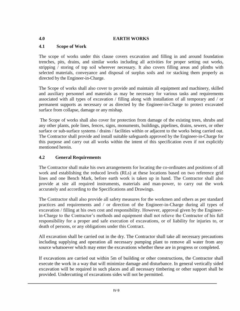
IV-9
4.0 EARTH WORKS
4.1 Scope of Work
The scope of works under this clause covers excavation and filling in and around foundation
trenches, pits, drains, and similar works including all activities for proper setting out works,
stripping / storing of top soil wherever necessary. It also covers filling areas and plinths with
selected materials, conveyance and disposal of surplus soils and /or stacking them properly as
directed by the Engineer-in-Charge.
The Scope of works shall also cover to provide and maintain all equipment and machinery, skilled
and auxiliary personnel and materials as may be necessary for various tasks and requirements
associated with all types of excavation / filling along with installation of all temporary and / or
permanent supports as necessary or as directed by the Engineer-in-Charge to protect excavated
surface from collapse, damage or any mishap.
The Scope of works shall also cover for protection from damage of the existing trees, shrubs and
any other plants, pole lines, fences, signs, monuments, buildings, pipelines, drains, sewers, or other
surface or sub-surface systems / drains / facilities within or adjacent to the works being carried out.
The Contractor shall provide and install suitable safeguards approved by the Engineer-in-Charge for
this purpose and carry out all works within the intent of this specification even if not explicitly
mentioned herein.
4.2 General Requirements
The Contractor shall make his own arrangements for locating the co-ordinates and positions of all
work and establishing the reduced levels (RLs) at these locations based on two reference grid
lines and one Bench Mark, before earth work is taken up in hand. The Contractor shall also
provide at site all required instruments, materials and man-power, to carry out the work
accurately and according to the Specifications and Drawings.
The Contractor shall also provide all safety measures for the workmen and others as per standard
practices and requirements and / or direction of the Engineer-in-Charge during all types of
excavation / filling at his own cost and responsibility. However, approval given by the Engineer-
in-Charge to the Contractor’s methods and equipment shall not relieve the Contractor of his full
responsibility for a proper and safe execution of excavations, or of liability for injuries to, or
death of persons, or any obligations under this Contract.
All excavation shall be carried out in the dry. The Contractor shall take all necessary precautions
including supplying and operation all necessary pumping plant to remove all water from any
source whatsoever which may enter the excavations whether these are in progress or completed.
If excavations are carried out within 5m of building or other constructions, the Contractor shall
execute the work in a way that will minimize damage and disturbance. In general vertically sided
excavation will be required in such places and all necessary timbering or other support shall be
provided. Undercutting of excavations sides will not be permitted.

IV-10
In the case where, in the opinion of the EIC, the works are likely to cause interference to the
public, the Contractor shall organize his operations in such a way as to reduce to a minimum the
interval between opening up and back-filling the excavations. No further work shall commence
until the EIC has inspected and approved the completed excavation.
All excavation operation shall include excavation and “getting out” the excavated material.
“Getting out” shall include throwing the excavated material; as directed by the Engineer-in-
Charge.
The excavation shall conform to the lines, grades, side slopes and levels shown on the drawing or
as directed by the Engineer-in-Charge. The contractor shall not excavate outside the limits of
excavation. Subject to the permitted tolerances, any excess depth/ width excavated beyond the
specified levels/dimensions on the drawings shall be made good at the cost of the contractor with
suitable material of characteristics similar to the removed and compacted to the requirements.
All debris and loose material on the slopes of cutting shall be removed. No backfilling shall be
allowed to obtain required slopes excepting that when boulder or soft materials are encountered
in cut slopes, these shall be excavated to approved depth on instructions of the Engineer-in-
Charge and the resulting cavities filled with suitable material and thoroughly compacted in an
approved manner.
After excavation the sides of excavated area shall be trimmed and the area contoured to minimize
erosion and ponding, allowing for natural drainage to take place. If trees were removed, new
trees shall be planted, as directed by the Engineer-in-Charge. The cost of planting new trees shall
be deemed to be incidental to the work.
All materials obtained from excavation shall remain Owner’s property. All salvaged materials of
archaeological importance or of value in the opinion of the Engineer-in-Charge shall be
segregated from the excavated materials and stacked separately in a regular manner at locations
as directed by the Engineer-in-Charge. Within fifteen (15) days of taking over of the site, the
Contractor shall submit to the Engineer-in-Charge for approval, his proposal for excavation
together with pertinent data for each stage of excavation in each work area. The Contractor shall
furnish the following details in his proposal:
a. Details of the proposed setting-out methods before commencing the work.
b. Descriptions of working methods and sequences of excavation.
c. Proposals for controlling ground water and details of associated plant and equipment
proposed to be deployed, where dewatering is felt necessary.
d. Preliminary design and procedures for blasting and blast monitoring if proposed to be
necessary, including name and qualifications of Blasters [copies of valid Blaster's
Certificates for Blasting Supervisor and Blasters to be attached], commercial
description and technical information for the blasting products (explosive, detonator,
fuses, etc.) proposed, capacity of explosives and detonator magazines, elements of
drilling, charging, delay patterns and weight of explosive to be detonated per day, etc.

IV-11
4.3 Specifications and Standards
The methods and practices for all types of excavation shall conform to the Specifications for
Building and Road Works, 2015: Royal Govt. of Bhutan and / or latest editions of the Indian
Standards, subject to the approval of the Engineer-in-Charge.
A. EXCAVATION
4.4 Classification of Excavation
Excavation shall be classified depending upon the type of soil encountered during excavation
from ground surface or below the finished stripped level and also for purpose of payment. The
type of soil in excavation shall be classified as follows:
a. Excavation in Soil
b. Excavation in Rock
4.4.1 Excavation in Soil
Excavation in soil includes excavation in all kinds of soil such as vegetable or organic soil, turf
gravel, sand, silt loam, clay, peat, gravel; cobble stone, boulders upto one man size etc, which
requires close application of picks or jumpers or scarifies to loosen.
Excavation in soil also includes excavation in soft rock like lime stone, sand stone, hard laterite,
hard conglomerate and un-reinforced cement concrete below ground level, which can be
excavated by splitting with crow bars or picks and does not require blasting, wedging or similar
means of excavation.
4.4.2 Excavation in Rock
Rock when encountered in excavation shall be removed upto the formation level or as otherwise
indicated on the drawings. Where, however, unstable shales or other unsuitable material are
encountered at the formation level, these shall be excavated to the extent of 500mm below the
formation level or as otherwise specified. In all cases, the excavation operation shall be so carried
out that at no point on cut formation the rock protrudes above the specified levels. Rock and large
boulder which are likely to cause differential settlement and also local drainage problems should
be removed to the extent of 500 mm below the formation level in full formation width including
drains and cut through the side drains.
Where excavation is done to levels lower than those specified, the excess excavation shall be
made good to the satisfaction of the Engineer-in-Charge.
Slopes in rock cutting shall be finished to uniform lines corresponding to slope line shown on the
drawing or as directed by the Engineer-in-Charge. Notwithstanding the foregoing, all loose
pieces of rock on excavated slope surface shall be removed.
When blasting is to be resorted to the same shall be carried out to clause 4.5 and all precautions
indicated therein observed.

IV-12
4.5 Blasting
Where hard rock is met with and blasting operations are considered necessary, the Contractor
shall obtain the approval of the Engineer-in-Charge. For an ordinary rock, in general, blasting
operation shall not be carried out unless permitted by the Engineer-in-Charge. All blasting
operations including the depth and size of holes and the size and characteristics of charges shall
be subject to the approval of the Engineer-in-Charge. The Contractor shall submit all such
information to the Engineer-in-Charge for approval at least 14 days prior to starting blasting
operation.
The Contractor shall obtain a license from the competent authority for obtaining and storing the
explosives. The Contractor shall procure the explosives, fuses, detonators, etc from the
Government of Bhutan (RGoB) or as per the provision in terms and conditions of the Contract.
The Engineer-in-Charge or his authorized Representatives shall have the right to check the
Contractor’s store and accounts of explosives. The Contractor shall provide all facilities for this.
The Contractor shall also comply strictly with the regulations as required by the concerned
authorities of RGoB, regarding purchase, storage, issue and use of explosives and detonators and
transport of same to and from site.
Blasting shall be carried out at specified times to be agreed upon between the Contractor and the
Engineer-in-Charge. Contractor shall take all precautions as per rules for blasting operations as
per latest RGoB blasting manuals and shall be responsible for any damage done to the Work or
any damage arising out of accident to the workmen, public or property due to storage,
transportation and use of explosives during blasting.
4.6 Disposal and Stockpiling of Materials from Excavation
All the excavated material shall be the property of the employer. The material obtained from the
excavation of benches & foundations of buildings, roadway, shoulders, verges, drains, cross-
drainage works etc., shall be used for filling up of (i) roadway embankment, (ii) the existing pits
in the right-of-way and (iii) for landscaping of the road as directed by the Engineer-in-Charge,
including leveling and spreading and disposal of surplus soil at the designated dumping area or as
directed by the Engineer-in-Charge and no extra payment shall be made for the same.
4.7 Excavation Tolerances
The following tabulated tolerances shall apply for all excavations
Description Excavation Tolerance (cm)
a. bed or formation levels for construction +0, -10
b. side slope (perpendicular to slope) +4, -10
c. top elevation +10, -0
The Engineer-in-Charge may require that the Contractor repair or remove at his own expense, any
material that exceeds the limits above specified.
IV-13
4.8 Dewatering
The Contractor shall construct, operate and maintain drainage systems, including drainage
trenches, pumps, pump sumps, pipelines etc., to sufficiently dewater all appearing water, service
water and underground water encountered during excavation, in order to allow for the
workmanlike execution of all excavation works. All costs for dewatering systems including
drainage trenches, pump sumps, pumps, pipelines, etc., shall be included in the unit prices in the
Schedule of Quantities for excavation and construction of foundation as specified in sub-clause
4.11.2.3.
4.9 Slides
If slips, slides, over-breaks or subsidence occur in cutting during the process of construction, they
shall be removed at the cost of the contractor as ordered by the Engineer-in-Charge. Adequate
precautions shall be taken to ensure that during construction, the slopes are not rendered unstable
or given rise to recurrent slides after construction. If finished slopes slide into the roadway
subsequently, such slides shall be removed and paid for at the contract rate, provided the slides
are not due to any negligence on the part of the contractor.
4.10 Slopes Support and Protection
The Contractor is responsible for all necessary safety measures. From the commencement of
work until certificate of completion, the Contractor shall strictly follow the safety regulations in
order to prevent accidents. Proper strutting, including rearrangements of the struts when
necessary, protection of slopes, methods of excavation to reduce risk of slides, etc. shall be
deemed to be included in the unit prices. In the event of soil slides occurring during earth and
rockwork, all damage will be to the Contractor's account. All additional work from such damage
will not be paid for. Where the nature of the soil gives reason to fear of any movement, initial
excavation operations shall be carried out with special care. All planking, strutting and supports
necessary to retain the sides of the excavations shall be provided, erected and maintained in a
safe condition by the Contractor.
Excavation shall not be carried out below foundations of any structure without prior approval of
the Engineer-in-Charge, until underpinning and shoring etc. to be performed by the Contractor,
have been completed. All existing structures, pipes and foundations, if any, which are to be
incorporated into the final work, shall be adequately protected or replaced by the Contractor.
4.11 Measurement and Payment
4.11.1 Measurement
Measurement for excavation will be made according to the volume of solid mass, actually
excavated in its natural state by measuring the length, breadth and depth of cutting corrected upto
4mm. The volume computations shall be based on surveys of the original ground surface and / or
rock surface after completion of final excavation. Excavation in soil and rock shall be measured
separately.
Excavation work for Working Facilities, e.g. access and temporary service roads, camps, etc.,
will not be measured. The Contractor shall include the costs of such works in the respective pay-
items.

IV-14
4.11.2 Payment
4.11.2.1 General
Payment for excavation in soil or rock shall be made at the unit prices tendered in the Bill of
Quantities. The Unit prices shall include the all costs required for carrying out all operations
including labour, materials, equipment , tools and plants, drilling and blasting, protection,
drainage and dewatering, and cleaning of excavation surface, stockpiling, transportation and
disposing the excavated materials and incidentals necessary to complete the work.
Damages or alterations caused by wrong blasting or due to any other incorrect operation by the
Contractor shall be repaired at his expense in a manner acceptable to the Engineer-in-Charge.
4.11.2.2 Payment for Over-excavation
(1) Over - excavation due to Geological Conditions
The cost incurred in connection with cave-ins and rock falls due to geological conditions will be
reimbursed to the Contractor, subject to the approval of the Engineer-in-Charge, at the reduced
rate only in case of unexpected and unavoidable occurrences, which could not be avoided by
proper excavation and support methods.
(2) Over-excavation due to Contractor's Fault
Where over-excavation is caused by inappropriate working methods or negligent work (e.g.
wrong location of drill holes, careless blasting operations, excessive pulls, etc.), no payment will
be made either for the over-excavation / over-break beyond the pay line or for the additional
concrete required for filling. The Contractor shall be responsible for all cave-ins, erosion and
over-break due to the Contractor's fault. He shall take all necessary measures at his own cost, to
control the excavation and make all the repairs ordered by the Engineer-in-Charge.
(3) Extra Excavation Required for Operational Reasons
Extra excavation not described in the Bill of Quantities or not shown on the Drawings, but
considered necessary by the Contractor for his operations in excavation or for supply facilities
and the like may be made only if approved by the Engineer-in-Charge. The cost of such
excavation including supporting work and of the concrete required to fill them shall be included
in the unit prices of excavation in the Bill of Quantities and shall not be paid separately even
though their construction has been approved by the Engineer-in-Charge.
4.11.2.3 Payment for Dewatering
No measurement and payment for Dewatering shall be made extra. All cost of dewatering during
excavation and construction of foundation of any structure shall be included in the Unit Rates in
the respective Bill of Quantities.
IV-15
B FILLING
4.12 Definition of Fill
The expression ‘fill’ shall be taken to mean backfill as well as fill in trenches and is deemed to
include excavation from trenches / borrow area or stockpile, loading/ unloading, transport up to 2
km radius, spreading / placing, compaction and trimming to final profile and any moisture control
measures required to bring the fill to within specified moisture content whether drying or wetting
measures.
4.13 Fill Material
Materials to be used for filling purposes shall be obtained in general, from the excavated earth.
The fill materials shall be clean and free from shingle, organic matters, roots and excessive
amount of sand, lumps, concrete or any other foreign substances which could harm or impair the
strength of the sub-structure in any manner. Fines less than 74microns shall not be more than
20%. In any case, materials to be used for filling shall have the prior written approval of the
Engineer-in-Charge.
Filling in plinth and under floors shall be done with sand or otherwise as directed by the Engineer-
in-Charge. Materials required for filling / banking in the Works, if not available from the required
excavation shall be obtained from the Designated Borrow Area. Some degree of selection may be
required by the Engineer-in-Charge within the Designated Borrow Area. Where access to suitable
material within the borrow area is not possible, the borrow area’s site shall be cleared and/ or
grubbed at the Contractor’s expense.
4.14 Execution of Filling
After completion of foundation, footings, plinth, walls, and other construction below the
elevation of the final grades and prior to filling, all temporary shoring, timber, etc shall be
sequentially removed and the excavation cleaned of all trash, debris and perishable materials. If
antitermite treatment is required to be done, the same should be done as directed by the EIC.
Filling shall begin only with the written approval of the Engineer-in-Charge. Also, area identified
for filling shall be cleared of all soft pockets, vegetation, bushes, slush, etc. In case of plinth and
similar filling, the ground shall be dressed and consolidated by ramming and light rolling by
portable mechanical compacter.
Filling in plinth and under floors shall be with clean sand and free from dust, organic and foreign
matter and its grading shall be as approved by the Engineer-in-Charge. Sand filling in plinth shall
be in a manner similar to earth filling as specified above except that consolidation shall be done
by flooding with water. The surface of the consolidated sand filling shall be dressed to the
required level or slope and shall not be covered till inspected and approved by the Engineer-in-
Charge.
Fill adjacent to pipes shall be free of stones, concrete, etc and shall be hand placed and
compacted uniformly on both sides of the pipes and where practicable up to a minimum depth of
400mm over the top of pipes . While tamping around the pipes, care should be taken to avoid
unequal pressure.
IV-16
Filling shall be accurately finished to the line, slope, cross section and grade as shown on the
Drawings. Finished surface shall be free of irregularities and depressions and shall be within
20mm of the specified level.
4.15 Measurement and Payment
4.15.1 Measurement
Filling with excavated earth, borrowed earth and sand shall be measured separately. For filling of
sides of the foundations, the cubical contents of bed concrete leveling course and masonry / concrete
in foundations upto the ground level shall be worked out and the same shall be deducted from the
cubical contents of earth work in excavation for foundations already measured under the respective
item of earth work to arrive at the quantity of filling for sides of foundations.
Filling in plinth and under floors shall be measured by cubical contents of the filling after
consolidation.
4.15.2 Payment
Payment for filling either from excavated earth or borrowed earth or sand shall be made as per the
Unit Rates tendered in the Bill of Quantities. The unit rates shall cover the cost of all the required
filling operations including cost of labour , materials, equipment, tools and plants, watering,
consolidation, etc and incidentals necessary to complete the work. No additional payment will be
made for preparation of the borrow area.
4.16 Sand filling
Sand filling shall be done, similar to earth filling, except that the consolidation is done by
flooding with water. The surface of the consolidated sand shall be dressed to required level or
slope. Any other operations on top of the sand fill shall not be started until the Engineer-in-
Charge has inspected and approved the sand filling.
The measurement shall be made for consolidated volume of sand filling. The dimensions shall be
measured correct to 10mm and cubical contents worked out in cubic metre correct to two places
of decimal.
The rates shall cover the cost for carrying out all the required filling operations including cost of
labour, materials, equipment hired/owned, tools and plants, and incidentals necessary to complete
the work.
5.0 MASONRY WORKS
5.1 Scope of Works
The Scope of Works covered under this clause shall comprise of masonry (Brick or Stone)
works including supply of all construction materials, equipment, tools and plants, labour (skilled
or un-skilled) , etc. as would be required for construction of all types of masonry as shown in
the Drawings and as specified herein and / or as directed by the Engineer-in-Charge.
The Scope of Works shall also include to provide all structural parts, scaffolding, transportation,
loading, unloading, inspection, test and quality control , preparation of foundation surfaces,
adjustment of surfaces adjacent to the walls, linings, pavements, including curing and protection,
IV-17
etc. and all other incidentals and operations required to complete the masonry works in all
respects.
5.2 General Requirements
All materials and structural parts incorporated in the permanent work shall be new and unused.
Quality and dimensions of materials as well as works shall comply with these Specifications and
approved Standards.
All masonry shall be carried out in a workman like manner at the highest standards and all works
shall be coordinated with the other works carried out at the site to allow the performance of all
works simultaneously without causing any hindrance to other works.
The Contractor shall also provide all safety measures for the workmen and others as per standard
practices and requirements and / or direction of the Engineer-in-Charge during all masonry
works at his own cost and responsibility. However, approval given by the Engineer-in-Charge to
the Contractor’s methods and equipment shall not relieve the Contractor of his full responsibility
for a proper and safe execution of masonry, or liability for injuries to, or death of persons, or any
obligations under this Contract.
5.3 Submission
At least fifteen (15) days prior to commencement of the masonry work, the Contractor shall
submit the details of schedule of works to the Engineer-in-Charge for approval. Submission shall
also include details of source of supply of Bricks, Stones, Cement, Sand for mortar, indicating
the estimated quantity to be obtained from each source and all other requisite materials.
Approval of plant and equipment or their operation or of any construction procedure will not
waive or modify any provisions or requirements contained in this Specification governing the
quality of the materials or the finished work.
5.4 Classification of Masonry
The masonry works shall be classified as mentioned in Table -5.1. The required works shall be
executed as per drawing, specifications and / or as directed by the Engineer-in-Charge
Table -5.1
Classification of Masonry
Type of masonry Classification Cement-mortar Mix
Brick Masonry BM 1 (Cement) : 4 (Sand)
Random Rubble Masonry RRM 1 (Cement) :6 (Sand)
Coursed Rubble Masonry CRM 1 (Cement) : 4 (Sand)
Concrete Block Brick
Masonry CBM 1 (Cement) : 4 (Sand)
IV-18
5.5 Execution
5.5.1 General
The mortar for all masonry works shall consist of cement, sand as specified above and water
with or without admixtures as approved by the Engineer-in-Charge, each complying with its
specifications. The quantity of water shall be as necessary to obtain a satisfactory workability
regarding the use of the mortar. Quality of mortar shall in general, meet the requirements
specified in IS: 2250 (Code of Practice and Use of Masonry mortar).
5.5.2 Mixing, Transporting and Placing
The unit of measurement for cement shall be a bag of cement weighing 50kg and this shall be
taken as 0.035 cubic metre. Sand in specified proportion shall be measured in boxes of size: 35 x
25 x 40 cm. It shall be measured on the basis of its dry volume. In case of damp sand, its
quantity shall be increased suitably to allow for bulking.
Mortar for masonry shall invariably be produced in a mechanical mixture by volume batching.
The mortar shall be mixed in small batches such that the quantity of mortar so prepared at a time
could be completely used up in masonry within 30 minutes of mixing. Mortar that has remained
longer than this period or that has become stiff or set on account of delay in consumption or
otherwise shall be rejected at the Contractor’s cost.
Cement and sand in the specified proportions shall be mixed dry thoroughly in a mixer. Water
shall then be added gradually and wet mixing continued for at least two minutes. Care shall be
taken not to add more water than that which shall bring the mortar to the consistency of a stiff
paste. Only the quantity of mortar, which can be used within 30 minutes of its mixing shall be
prepared at a time. The drum shall be totally emptied before a new batching cycle is started. The
drum shall be kept free from hardened mortar and shall be thoroughly cleaned prior to change of
mix or on cessation of mixing.
Hand-mixing for small batches may be approved by the Engineer-in-Charge. However, the
mortar shall be mixed up to the degree obtained with a mechanically operated mixer. Prior to
adding water to the mix, sand, cement and admixture (if required) shall be mixed dry thoroughly
in a leveled platform until the mixture has a uniform colour. The quantity of dry mix , which can
be used within 30 minutes, shall then be mixed in masonry trough with just sufficient quantity of
water to bring the mortar to the consistency of a stiff paste.
The equipment and tools used for transporting and placing of mortar shall ensure that
contamination or loss of ingredients do not take place. Mortar shall be stirred or worked at
frequent intervals to prevent separation. In case, the mortar has stiffened because of evaporation
of water from the mortar, it may be re-tampered by adding water frequently as needed to restore
the requirements of consistency but this re-tampering shall be permitted only upto 2 hours from
the time of original addition of water. Mortar unused for more than two hours shall be rejected
and removed from the site of work.
IV-19
5.6 Brick Masonry/Concrete Block Brick Masonry
5.6.1 General Physical Characteristic of Bricks
A good first class Bricks should be sound, hard and well burnt with uniform size, shape and
coloured (generally deep red or copper), homogeneous in texture and free from flaws and cracks.
A fractured surface should show a uniform compact structure free from holes, lumps or grit. The
surface shouldn’t be too smooth as otherwise mortar will not stick to it. Arises should be square,
straight and sharply defined. No dimension of first class brick to vary more than 3 mm form the
standard size. A brick should give a metallic ring when struck with the small hammer or another
brick. A good brick should not break when struck against another brick or when dropped flat
from the height of about 1.2 to 1.5 m on the ground. It should have a surface so hard that cannot
be scratched by the finger nail.
A first class brick should not absorb more than 1/6th of its weight when dry and a second class
brick not more than 1/4th, after immersion in water for 1 hour. Brick of low porosity have greater
strength. All brick should be soaked in water for at least one hour before work with cement
mortars.
The cessation of bubbles through the water is an indication of saturation being complete. A
“Frog” or “Kick” is made 6mm deep and bricks are usually laid frog up which affords a key for
the mortar. A small proportion of lime, not exceeding 5% in fairly divided state is useful in brick
Earth. Bricks containing oxide of iron lends the bricks to its peculiar red colour and whereas
magnesia gives a yellow tint. Bricks containing small amount of alkali is good as it has an
influence on plasticity of clay. The Bricks should show no sign of effloresce after soaking in
water and drying in the shade. Bricks containing iron pyrites, salts, pebbles, nodules of kankar,
gravel and tree roots should be avoided.
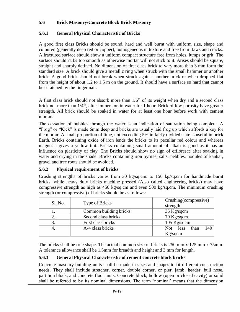
5.6.2 Physical requirement of bricks
Crushing strengths of bricks varies from 30 kg/sq.cm. to 150 kg/sq.cm for handmade burnt
bricks, while heavy duty bricks machine pressed (Also called engineering bricks) may have
compressive strength as high as 450 kg/sq.cm and even 500 kg/sq.cm. The minimum crushing
strength (or compressive) of bricks should be as follows:
Sl. No. Type of Bricks Crushing(compressive)
strength
1. Common building bricks 35 Kg/sqcm
2. Second class bricks 70 Kg/sqcm
3. First class bricks 105 Kg/sqcm
4. A-4 class bricks Not less than 140
Kg/sqcm
The bricks shall be true shape. The actual common size of bricks is 250 mm x 125 mm x 75mm.
A tolerance allowance shall be 1.5mm for breadth and height and 3 mm for length.
5.6.3 General Physical Characteristic of cement concrete block bricks
Concrete masonry building units shall be made in sizes and shapes to fit different construction
needs. They shall include stretcher, corner, double corner, or pier, jamb, header, bull nose,
partition block, and concrete floor units. Concrete block, hollow (open or closed cavity) or solid
shall be referred to by its nominal dimensions. The term ‘nominal’ means that the dimension

IV-20
includes the thickness of the mortar joint. Actual dimensions shall be 10 mm short of the nominal
dimension (or 6 mm short in special cases where finer joint is specified). Their nominal
dimensions shall be as follows:
Length 400, 500 or 600 mm
Height 75, 100 or 200 mm
Width 50, 75, 100, 125, 150, 200, 250 or 300 mm
SPECIFICATIONS FOR BUILDING & ROAD WORKS 2009
In addition, concrete blocks shall be manufactured in half lengths of 200, 250 or 300 mm to
correspond to the full lengths and also as specified. The maximum variation in the length of units
shall not be more than ± 5 mm and maximum variation in height and width of unit, not more than
± 3 mm. Hollow concrete blocks shall be made either with two cores or three cores. Stretchers in
the 200, 250 and 300 mm widths shall generally have concave ends, each end flange being
grooved or plain. All 100 and 150 mm wide units shall generally be made with plain ends. Face
shells and webs shall increase in thickness from the bottom to the top of the unit. Depending
upon the core moulds used, the face shells and webs shall be flared and tapered or straight
tapered, the former providing a wider surface for mortar. The minimum thickness of the face
shell and web shall be not less than 20 mm. However, for the top face shell of the closed cavity
units, the minimum thickness may be less than 20 mm, but not less than 15 mm. Subject to the
tolerances and the provisions, the faces of masonry units shall be flat and rectangular, opposite
faces shall be parallel, and all arises shall be square. The bedding surfaces shall be at right angles
to the faces of the blocks.
Non-load bearing concrete masonry units, hollow (open and closed cavity) or solid shall be used
in interior walls, partitions, panels and for exterior panel walls in steel or reinforced concrete
frame construction when protected from weather by rendering or by some other efficient
treatment.
The concrete mix used for blocks shall not be richer than one part by volume of cement to 6 parts
of combined fine and coarse aggregates. Allowances shall be made for bulking of sand materials,
if necessary. Concrete shall be normally mixed in a mechanical mixer. Mixing shall be continued
until there is a uniform distribution of the materials, and the mass is uniform in colour and
consistency. Placing and compaction of the mixture shall be done in a mould either with hand
operated machine or mechanically operated machine. Immediately after the block is made, it
shall be released from the mould and removed with the pallet to a covered shed, to protect it
against sun and strong winds. The blocks shall be stored in the shed until they are sufficiently
hardened to permit handling without damage but in no case shall this period be less than 12
hours. The hardened blocks shall then be removed from the pallets and placed in a curing water
tank or taken to the curing yard, where these shall be kept continuously moist for at least 21 days.
When the blocks are cured in an immersion tank, the water of the tank shall be changed at least
every 4 days. Blocks can also be cured with pressure and non-pressure curing. After curing the
blocks shall be dried under shade for a period of 4 weeks before being used on the work. They
shall be stacked with voids horizontal to facilitate through passage of air. The blocks shall be
allowed to complete their initial shrinkage before they are laid in a wall.
Concrete masonry building units can be given a variety of surface textures ranging from a very
fine close texture to a coarse open texture by proper selection, grading and proportioning of the
aggregates at the time of manufacture and by treating the face of the units while still green.
Concrete masonry units used in constructing exposed walls shall be free from stains and
discolouration, blemishes or defects which detract the desired appearance of the finished wall.
Generally all units shall be sound and free from cracks or other defects, which interfere with
IV-21
proper placing of the units or impair the strength or performance of the construction. Minor
chipping resulting from the customary methods of handling during delivery, shall not be deemed
grounds for rejection.
5.6.4 Laying
The bricks should be laid by breaking joints in successive layer. Half or cut bricks should not be
used except where necessary for breaking the joints in successive layers. Close in such a cases
should be cut to the required size and used near the ends of walls. A layer of mortar mix specified
in the item shall be spread on full width of suitable length of lower course keeping the mortar
dropping to the minimum possible. Each brick shall be properly bedded and set home by gentle
tapping with handle of shovel or wooden mallet. The side face shall be buttered with mortar
before the next brick is laid and pressed against it. On completion of a course, the vertical joints
shall be fully filled from the top with mortar.
The wall shall be truly plumb. All courses should be laid truly horizontal and all vertical joints
should be truly vertical. The vertical joints in alternate layer shall come directly one over other. A
set of tools comprising of wooden straight edges, mason’s sprit level, square half metre rule line
and pins string and plumb shall be kept on the site of work.
All the connected bricks works shall be carried up nearly at one level and no portion of the work
shall be left more than one metre below the rest of the work. All item fixtures, pipes, out lets of
water, hold fasts of door and windows etc. which are required to be built in wall shall be
embedded in cement mortar or cement concrete as specified in their correct position as the work
proceeds.
5.6.5 Joints
Bricks shall be so laid that all joints are quite full of mortar. The thickness of joints shall not
exceed a cm. The face joints shall be raked to minimum depth of 10 mm by raking tool daily
during the progress of work. When the mortar is still green so as to provide proper key for
Plaster or pointing to be done where plastering or pointing is not required to be done, the joints
shall be struck flush and finished at the time of laying.
The face of brick work shall be cleaned the very day that brick work is laid daily and all mortar
dropping removed.
5.6.6 Curing
Green work shall be protect from rain by suitable covering. Masonry shall be kept constantly
moist on all the faces for a minimum period of seven days.
5.6.7 Scaffolding
Single scaffolding having one set of vertical support shall be allowed. The support shall be sound
and strong, tied together by horizontal pieces, over which the scaffolding planks shall be fixed.
The inner end of the horizontal scaffolding member may rest in a hole provided in the masonry,
such holes; however, left in masonry work for supporting the scaffolding shall be filled and made
good before plastering.
5.6.8 Measurement
The length and height shall be measured correct to a cm and area calculated correct to 0.1 sq.m.
IV-22
5.6.9 Rate
Rate shall include all materials and labour described above including scaffolding where
necessary.
5.7 Random Rubble Masonry
5.7.1 General
The stones shall be hard, sound and durable of approved quarry, approved by the Engineer-in-
Charge before used in the works. Stones shall be hammer dressed to seem closed joint so that the
stones when laid will come into closed proximately. Stones would be fairly equal and no stones
shall be less than 15cm in size. Mortar shall be as specified and material of mortar shall be as per
standard specifications.
Through bond stones of one piece shall be provided one for every 0.5 sqm of face and should be
extended to the full thickness of a wall. All stones shall be thoroughly wetted before laying. The
masonry shall be kept moist for a period of 10 days and shall be protected from sun, rain, frost
and other weather effect.
5.7.2 Scaffolding
Single scaffolding having one set of vertical support shall be allowed. The supports shall be
sound and strong, tied together by horizontal pieces, over which the scaffolding planks shall be
fixed. The inner end of the horizontal scaffolding member may rest in a hole provided in the
masonry. Such holes, however, shall not be allowed in pillars under one metre in width or
immediately near the skew back of arches.
The holes left in masonry work for supporting scaffolding shall be filled and made good with
cement concrete 1:3:6 (1 cement : 3 coarse sand : 6 stone aggregate 20mm nominal size).
5.7.3 Curing
Masonry work in cement or composite mortar shall be kept constantly moist on all faces for a
minimum period of seven days.
5.7.4 Protection
Green work shall be protected from rain by suitable covering. The work shall also be suitably
protected from damage, mortar drooping and rain during construction.
5.7.5 Measurements
The length, height and thickness shall be measured correct to a cm. The thickness of wall shall be
measured at joints, excluding the bushings. Only specified dimensions shall be allowed anything
extra shall be ignored. The quality shall be calculated in cubic metre nearest to two places of
decimal.
5.7.6 Rate
The rate shall include the cost of materials, labour and all lead and lift required for all the
operations described above.
5.7.7 Water Proofing Materials in Cement Mortar.
5.7.8 General
The waterproofing compound shall be mixed in the proportion and in the ways as recommended
by the manufacturers.

IV-23
5.7.9 Measurement
Cubical contents shall be worked out in cu.m corrected to two places of decimal only for the
volume where cement mortar is mixed with water proofing compound.
5.7.10 Rate
The rate shall include the cost of water proofing compound and labour involved in mixing the
compound with cement mortar.
5.7.11 Hand packed stone filling or soling with stone
Stones as obtained from the quarry shall be packed with their broader surface as base. The
packing shall be as dense as possible and the interstice shall be filled with small stones. The
height of stones shall be as per the thickness of soling required. The stones shall be arranged
neatly and the joints shall be as thin as possible.
5.7.12 Measurement
The length, breadth and height shall be measured correct to 10mm and the volume calculated
correct to 0.01 cu.m
5.7.13 Rate
The rate shall include the materials and labour involved in all operation described above.
6.0 CONCRETE WORKS
6.1 Scope of Work
The Scope of works under this clause covers concrete works (PCC and RCC) which shall consist
of:
Supply of all concrete constituents including reinforcements, labour, equipment, tools and
plants, joint materials etc.
Manufacturing, cooling, transporting, placing, consolidating, protecting and curing of concrete
Constructing, erecting and dismantling of form work
Placing materials for expansion and construction joints
Placing reinforcements and embedded items.
The Contractor shall also provide all safety measures for the workmen and others as per standard
practices and requirements and / or direction of the Engineer-in-Charge in execution of concrete
works at his own cost and responsibility. However, approval given by the Engineer-in-Charge to
the Contractor’s methods and equipment shall not relieve the Contractor of his full responsibility
for a proper and safe execution of concreting, or of liability for injuries to, or death of persons, or
any obligations under this Contract.
6.2 Definitions
a. Fine aggregate (Sand)
Fine aggregate is defined as the part of aggregate having a maximum dimension of 4.8 mm.
b. Coarse aggregate
Coarse aggregate is defined as the part of aggregate having a minimum dimension of 4.8 mm and
maximum of 40 mm.
IV-24
c. Construction Joint
Concrete surfaces, upon or against which concrete is to be placed or where new concrete is to be
adhered, that have become so rigid that the new concrete cannot be incorporated integrally with
that previously placed are defined as construction joints.
d. Expansion or Contraction joint
All joints allowing relative movement of concrete structures with respect to an adjacent one, due
to expansion, shrinkage, settlement of foundations etc. are to be considered expansion or
contraction joints.
6.3 Submission
The Contractor shall perform the concrete works in accordance with the Specifications, the
Drawings and the instructions of the Engineer-in-Charge. At least seven (7) days prior to
commencement of the concrete work, the Contractor shall submit the details of materials of
concrete and schedule of concreting to the Engineer-in-Charge for approval.
The approval given by the Engineer-in-Charge to the Contractor’s plants and equipment or their
operation or any construction method shall not relieve the Contractor of his full responsibility for
the proper and safe execution of concrete work or any obligations under the Contract.
6.4 Materials
All materials like cement, aggregates, water, admixture, etc as would be required for production
of concrete shall conform to the Specifications for Building & Road works, 2015, RGoB / IS
Codes
6.5 Execution of Concrete Works
6.5.1 General Requirement
The concrete (Plain or RCC) to be produced and placed according to the Specifications, shall be
of highest quality and uniformity. In all phases of operations, the Contractor shall be subject to
strict inspection and tests to assure concrete of the best quality. Special emphasis shall be made
on the uniformity of the concrete aggregates, water-cement ratio, consistency, air content and the
temperature control of the concrete at the time of placement in the formwork, as well as the
density and finishing when placed.
The Contractor shall be fully responsible for producing and maintaining the quality of concrete
with especially compressive strength not inferior to the specified one, except if different
instructions are given by the Engineer-in-Charge.
The Engineer-in-Charge shall have the right to reject concrete in any of the following events:
(i) When mixing operations have not been started within thirty (30) minutes after the
cement is added to the aggregates or,
(ii) when more than fifteen (15) minutes have elapsed between the discharging of the mixer
and the actual placing of the concrete, without agitating the concrete mix or,
(iii) when more than one (1) hour has elapsed between the adding of the cement to the
aggregates, and the actual placing of the concrete.
IV-25
The Engineer-in-Charge reserves the right to specify a lesser time, if hot weather or other
conditions cause quick stiffening of the concrete.
None of the concrete rejected by the Engineer-in-Charge shall be utilized in any of the
permanent works. The re-tempering of concrete, which has partially hardened, that is, remixing
with or without additional cement, aggregate or water shall not be permitted.
6.5.2 Execution of Plain Concrete Works (PCC)
6.5.2.1 Mixing of Concrete
Mixing of concrete shall be done by volume measure in the proportion as specified in the
drawing and / or as directed by the Engineer-in-Charge. Boxes of suitable size shall be used for
measuring sand and aggregates. The internal dimensions of the boxes shall be generally
35x25x40 cm deep or as otherwise approved by the Engineer-in-Charge. The unit of
measurement for cement shall be a bag of 50 kg and this shall be taken as 0.035cum.
While measuring the aggregates, shaking ramming or heaping shall not be done. The
proportioning of sand shall be on the basis of its dry volume and in case of damp sand, allowance
for bulkage shall be made by adopting the method prescribed under “Mandatory tests”.
Mixing shall be done in mechanical mixers. Mixing by hand shall be employed only in special
cases with the specific prior permission of the Engineer-in-Charge. Stone aggregate shall be
washed with water to remove dirt, dust or any other foreign materials, where necessary before
putting into the mixer.
a. Machine Mixing
Before starting mixing in a mixer, the mixer drum shall be flushed clean with water. Measured
quantity of dry coarse aggregate shall be placed in the skip followed by measured quantity of fine
aggregate and then cement. In case damp sand is used, add half of the quantity of coarse
aggregate followed by cement and sand. Finally add balance quantity of the coarse aggregate.
The skip shall be raised and dry materials slipped into the drum. The dry materials shall be mixed
for at least four turns of the drum, after which the correct quantity of water shall be added
gradually while the drum is in motion, to ensure even distribution with the dry material. The total
quantity of water for mixing shall be introduced before 25% of mixing time has elapsed and shall
be regulated to achieve the specified water- cement ratio. The materials shall be mixed for a
period of not less than 2 minutes and until a uniform colour consistency is obtained. The time
shall be counted from the moment at all the materials have been put into the drum.
The complete contents of the mixed concrete shall be emptied before recharging. When the mixer
closed down for the day or at any time exceeding 20 minutes, the drum shall be flushed clean.
b. Hand Mixing
Hand mixing shall be done on a smooth, clean and water-right platform of suitable size in the
following manner.
a) Measured quantity of sand shall be spread only
b) The cement shall be dumped on the sand and distributed evenly
c) The sand and cement shall be mixed intimately with spade, turning the mixture over and
over again, until it is of even colour throughout and free from streaks.
d) The sand cement mixture shall be spread out and measured quantity of coarse aggregate
shall be spread on its top. Alternatively the measured quantity of coarse aggregate shall be
spread out and the same cement mixture shall be spread on its top.
e) The above materials shall be mixed at least three times by shoveling and turning over by
twist from center to side, then back to the centre and again to the sides.
IV-26
f) A hollow shall be made in the middle of the mixed pile.
g) Three quarters of the total quantity of water required shall be added while the material is
turned in towards the centre with spades. The remaining water shall be added by water can
fitted with rose head, slowly turning the whole mixture over and again until a uniform
colour and consistency is obtained throughout the pile.
h) The mixing platform shall be washed at the end of the day.
6.5.2.2 Consistency and Slump of Concrete
Concrete shall be of a consistency and workability suitable for the conditions on the job. For
most concrete a "plastic" mix is required, which will not crumble, but will flow sluggishly when
vibrated, without segregation.
The quantity of water to be used for each mix of 50 kg cement , to give the required consistency
shall not be more than 34 litres for 1:3:6 mix, 30 litres for 1:2:4 mix, 27 litres for 1:1.5:3 mix and
25 litres for 1:1:2 mix. In the case of vibrated concrete, such limits specified may be suitably
reduced to avoid segregation. The quantity of water shall be regulated by carrying out regular
slump tests.
Slump tests shall be performed in accordance with the "Standard Method of Slump Test for
Consistency of Portland Cement Concrete"- IS-515.The Engineer-in-Charge may require to
adopt a stiffer consistency than that specified wherever concrete of such consistency can be
poured and be compacted easily by vibrators.
Wherever the limits for consistency and/ or slump are exceeded, the concrete shall be rejected
and removed at the Contractor's expense. The slumps as given in the Table 6.1 shall be adopted
for different kinds of work:
Table -6.1
Limit of Slump for Plain Concrete
Works Slump in mm
Vibrator Used Vibrator not used
Mass concrete in foundation, etc 10-25 50-75
Thin sections of flooring less
than 75 mm thickness 25-40 75-100
6.5.2.3 Strength of Concrete
The compressive strength on work tests for different mixes shall be as given in the table 6.2
Table - 6.2
Compressive Strength of Concrete
Mix Compressive strength in Kg./sq.cm
At 7 days At 28 days
1:1:2 210 315
1:1.5:3 175 265
1:2:4 140 210
IV-27
6.5.2.4 Placing of Concrete
The entire concrete to be used in the work shall be laid gently (not thrown) in layers not
exceeding 170 mm and shall be thoroughly vibrated by means of mechanical vibrators till a dense
concrete is obtained. The Engineer-in-Charge may however relax the condition specifying use of
mechanical vibrators at his discretion for certain items depending upon the thickness of the
members and feasibility of vibrating the same and permit hand compaction.
Hand compaction shall be done with the help of tamping rods so that the concrete is thoroughly
compacted and completely worked into the corners of the formwork. The layers of concrete shall
be so placed that the bottom layer does not finally set before the top layer is placed.
Compaction shall be completed before the initial setting starts i.e. within 30 minutes of addition
of water to the dry mixture. For items where the vibrators are not to be used, it shall be the duty
of the Contractor to take the permission of the Engineer-in-Charge before the start of work.
During cold weather, concreting shall not be done when the temperature falls below 4.70 C. The
concrete placed shall be protected against frost by suitable covering. Concrete damaged by frost
shall be removed and work redone. During hot weather, precaution shall be taken to see that the
temperature of wet concrete does not exceed 380 C.
When the placing of concrete is suspended, necessary removal of laitance and roughening the
surface for jointing future work shall be done before the concrete sets. When the work is resumed
the previous work must be thoroughly cleaned, roughened, watered and a grout of neat cement
slurry of the proportion, 1 kg of cement per litres of water applied uniformly.
6.5.3 Execution of Reinforced Concrete Works (RCC)
6.5.3.1 General Requirement
The production of concrete for RCC works shall be as specified under concrete works (plain),
vide para-6.5.2. Concrete shall be always mixed by mechanical mixer unless otherwise the
Engineer-in-Charge permits hand mixing.
6.5.3.2 Fabrication of Reinforcements
a. General
The reinforcements, in general, shall be of Fe 500 grade, unless otherwise specified. The
Contractor shall fabricate reinforcing steel to the dimensions and configurations as shown on the
Drawings or as approved by the Engineer-in-Charge.
b. Bending
All bars shall be cut to the lengths and bent in accordance with IS: 2502 the bar bending
schedules as approved by the Engineer-in-Charge.
Bars shall not be pre-heated for bending. Once bent, bars shall not be straightened or re-bent.
Bending of bars protruding from matured concrete for the purpose of clearing embedded items
shall be carried out only with the approval of the Engineer-in-Charge.

IV-28
c. Placing of Reinforcements
Before the reinforcement bars are placed, the surfaces of the bars shall be cleaned of flaky rust,
oil, or other foreign substances that are harmful to the bonding of reinforcement bars with
concrete. Reinforcement bars shall be accurately placed in the position as shown on the
Drawings or directed by the Engineer-in-Charge, and special care shall be exercised to prevent
the reinforcement bars from being displaced during the placement of concrete.
Intersecting points and splices of the reinforcement bars shall be fixed by using suitable clips or
annealed wires, the diameter of which shall be more than 0.7 mm. The reinforcement bars in
structures shall be placed and supported by use of precast spacer blocks to ensure required cover
between the reinforcement bars and the shutters. Unless otherwise shown or approved, the
minimum cover of concrete to reinforcing steel shall be as in Table 6.3.
Table 6.3
Minimum Cover of Concrete to Reinforcement Steel
Condition of Placement Minimum cover
(mm)
Structures exposed to weather, backfill or submerged
but accessible.
- DB 17 and smaller bars
40
Structures not exposed to weather or not in contact with
ground:
- beams, girders and columns principal reinforcing
steel, ties, stirrups and spirals
40
Upper-structure of buildings
- beams, girder, columns and slabs without finishing
- slabs with finishing
30
20
Sub-structure of buildings:
- beams, girders, columns and slabs
- footing
40
50
d. Splicing of Reinforcements
The number of splices shall be kept to a minimum. Location and length of lap splices shall be in
accordance with “IS Standards” (IS-456-2000 / SP-34).
e. Tolerance for Placing Reinforcing Steel
Unless otherwise required by the Engineer-in-Charge, reinforcement shall be placed within the
following tolerances:
(a) For effective depth of 200 mm or less ± 5 mm
(b) For effective depth more than 200 mm ± 15 mm
The overall shall, in no case, be reduced by more than one-third of specified cover or 5 mm
whichever is less.
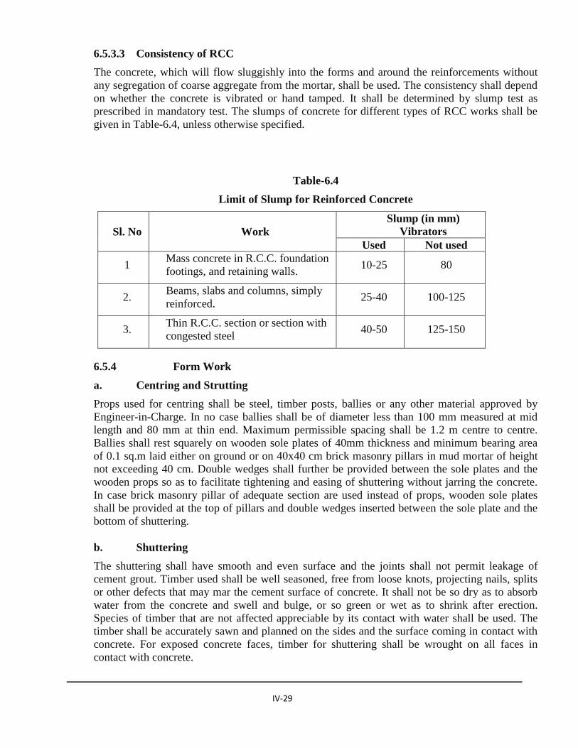
IV-29
6.5.3.3 Consistency of RCC
The concrete, which will flow sluggishly into the forms and around the reinforcements without
any segregation of coarse aggregate from the mortar, shall be used. The consistency shall depend
on whether the concrete is vibrated or hand tamped. It shall be determined by slump test as
prescribed in mandatory test. The slumps of concrete for different types of RCC works shall be
given in Table-6.4, unless otherwise specified.
Table-6.4
Limit of Slump for Reinforced Concrete
Sl. No Work
Slump (in mm)
Vibrators
Used Not used
1 Mass concrete in R.C.C. foundation
footings, and retaining walls. 10-25 80
2. Beams, slabs and columns, simply
reinforced. 25-40 100-125
3. Thin R.C.C. section or section with
congested steel 40-50 125-150
6.5.4 Form Work
a. Centring and Strutting
Props used for centring shall be steel, timber posts, ballies or any other material approved by
Engineer-in-Charge. In no case ballies shall be of diameter less than 100 mm measured at mid
length and 80 mm at thin end. Maximum permissible spacing shall be 1.2 m centre to centre.
Ballies shall rest squarely on wooden sole plates of 40mm thickness and minimum bearing area
of 0.1 sq.m laid either on ground or on 40x40 cm brick masonry pillars in mud mortar of height
not exceeding 40 cm. Double wedges shall further be provided between the sole plates and the
wooden props so as to facilitate tightening and easing of shuttering without jarring the concrete.
In case brick masonry pillar of adequate section are used instead of props, wooden sole plates
shall be provided at the top of pillars and double wedges inserted between the sole plate and the
bottom of shuttering.
b. Shuttering
The shuttering shall have smooth and even surface and the joints shall not permit leakage of
cement grout. Timber used shall be well seasoned, free from loose knots, projecting nails, splits
or other defects that may mar the cement surface of concrete. It shall not be so dry as to absorb
water from the concrete and swell and bulge, or so green or wet as to shrink after erection.
Species of timber that are not affected appreciable by its contact with water shall be used. The
timber shall be accurately sawn and planned on the sides and the surface coming in contact with
concrete. For exposed concrete faces, timber for shuttering shall be wrought on all faces in
contact with concrete.
IV-30
Wooden formwork with metal sheet lining of steel plates stiffened by steel angles shall also be
permitted. Where metal forms are used, all bolts and nuts shall be countersunk and well ground
to provide a smooth plane surface. The chamfers, beveled edges and moulding shall be made in
the formwork itself. Opening for a clamps and other fittings connected with services shall be
provided in the shuttering as directed by the Engineer-in-Charge. As for as practicable, clamps
shall be used to hold the forms together. Where use of nails is unavoidable minimum number of
nails shall be used and these shall be left projecting so that they can be easily withdrawn. Use of
double head nails shall be performed.
c. Surface Treatment for Shuttering
The surfaces of timber shuttering that would come in contact with concrete shall be well wetted
and coated with soap solution, raw linseed oil, form oil of approved manufacturer or any other
approved material (such as polythene/polyethylene sheets), to prevent adhesion of concrete to
form work. Soap solution, for the purpose shall be prepared by dissolving yellow soap in water to
get the consistency of paint. Inside surface of forms shall be thoroughly cleaned before
application or any of the materials mentioned above. Release agents shall be applied strictly in
accordance with the manufacturer’s instruction and shall not be allowed to come in contact with
any reinforcement. Re-use of the shuttering shall be permitted only after the inside surface has
been thoroughly cleaned in the manner described above.
Contractor shall give the Engineer-in-Charge due notice before placing any concrete in the forms
to permit him to inspect and accept the form work as to its strength alignment and general fitness,
but such inspection shall not relieve the Contractor of his responsibility for safety of workman,
machinery, materials and for results obtained.
d. Removal of Form Work
No formwork of any part thereof shall be removed without prior approval of the Engineer-in-
Charge. The formwork shall be so removed as not to cause any damage to concrete due to shock
or vibration. In a slab and beam construction, sides of beam shall be stripped first, then the under
sides of slab and lastly the underside of the beam. Formwork must be so designed that they can
be stripped in the order required i.e.
a) Shutters to vertical (non load bearing) faces e.g. column boxes, beam sides, wall forms,
b) Shutters forming soffits to slab, horizontal and inclined which carry only light load, e.g.
slab, roofs, floors and canopies etc.
c) Soffit shutters carrying heavy load e.g. beam and girder bottoms.
The whole of the formwork should be planned and a definite scheme of operation worked out. In
no circumstances should forms be struck until the concrete reaches strength of atleast twice the
stress of which the concrete may be subjected at the time of striking. Where possible the
formwork should be left longer as it would assist curing. Forms should be eased carefully in
order to prevent the load being suddenly transferred to concrete. The period that shall elapse after
the concrete has been laid, before easing and removal of centering and shuttering is undertaken
shall be as given in Table -6.5.
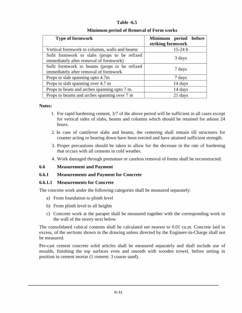
IV-31
Table -6.5
Minimum period of Removal of Form works
Type of formwork Minimum period before
striking formwork
Vertical formwork to columns, walls and beams 15-24 h
Sofit formwork to slabs (props to be refixed
immediately after removal of formwork) 3 days
Sofit formwork to beams (props to be refixed
immediately after removal of formwork 7 days
Props to slab spanning upto 4.7m 7 days
Props to slab spanning over 4.7 m 14 days
Props to beam and arches spanning upto 7 m. 14 days
Props to beams and arches spanning over 7 m 21 days
Notes:
1. For rapid hardening cement, 3/7 of the above period will be sufficient in all cases except
for vertical sides of slabs, beams and columns which should be retained for atleast 24
hours.
2. In case of cantilever slabs and beams, the centering shall remain till structures for
counter acting or bearing down have been erected and have attained sufficient strength.
3. Proper precautions should be taken to allow for the decrease in the rate of hardening
that occurs with all cements in cold weather.
4. Work damaged through premature or careless removal of forms shall be reconstructed.
6.6 Measurement and Payment
6.6.1 Measurements and Payment for Concrete
6.6.1.1 Measurements for Concrete
The concrete work under the following categories shall be measured separately:
a) From foundation to plinth level
b) From plinth level to all heights
c) Concrete work at the parapet shall be measured together with the corresponding work in
the wall of the storey next below.
The consolidated cubical contents shall be calculated net nearest to 0.01 cu.m. Concrete laid in
excess, of the sections shown in the drawing unless directed by the Engineer-in-Charge shall not
be measured.
Pre-cast cement concrete solid articles shall be measured separately and shall include use of
moulds, finishing the top surfaces even and smooth with wooden trowel, before setting in
position in cement mortar (1 cement: 3 coarse sand).

IV-32
No deduction shall be made for:
a) Ends of dissimilar materials (e.g. joists, beams, posts, girders, rafters, purlins, trusses,
corbels, step etc.) upto 500 sq.cm in section.
b) Opening upto 0.1 m2 or as specified.
c) Volume occupied by pipes, conduits, sheathing etc. not exceeding 100 sq. cm each in
cross sectional area.
d) Volume occupied by reinforcements
6.6.1.2 Payment for Concrete
Payment for concrete works shall be made at Unit Rates tendered in the Bill of Quantities. The
Unit rate shall include the cost for carrying out all the required operations including the cost of
labour, materials equipment, tools and plants, and incidentals, etc., but excluding reinforcement
and form work, necessary to complete the work
6.6.2 Measurements and Payment for Formwork
6.6.2.1 Measurement for Formwork
Formwork shall be measured separately (i) upto foundation and plinth and (ii) above for each of
the items as per Bill of quantities. All measurement shall be taken of the area of shuttering in
contact with the concrete surface. Dimensions of formwork shall be measured correct to 10mm.
No deductions from the shuttering due to the openings/obstructions shall be made if area of such
opening/obstructions does not exceed 0.1 sq.m. Nothing extra shall be paid for forming.
6.6.2.2 Payment for Form works
Payment for form work which includes centering and strutting for all heights, shall be paid
separately at Unit Rates tendered for the items specified in Bill of Quantities. Where it is not
specially stated in the description of the item that formwork shall be paid for separately, the rate
of the R.C.C. item shall be deemed to include the cost of formwork.
The Unit rate for form work shall include the cost of labour, materials, tools and plants and all
incidentals required for all operations including supporting the members until the concrete is
cured , set and hardened as required. No separate payment shall be made for items such as form
releasing agent, connections, provisions for openings and other items required for completion of
the work unless specified otherwise.
6.6.3 Measurement and Payment for Reinforcements
6.6.3.1 Measurement for Reinforcement
Measurement for reinforcing bars will be made for actual lengths of reinforcement bars
including permissible hooks, bends and splices will be measured. The weight of reinforcing bars
will then be calculated for each size of bar from the unit weight as stated on the certified copies
of manufacturer’s reports, which the Contractor shall submit to the Engineer-in-Charge or
otherwise standard weights per metre for each size of bars as provided in the Steel Tables shall
be used.

IV-33
Before starting concreting, the Contractor shall make sure that the measurements of reinforcing
bars placed in position have been recorded and that the Engineer-in-Charge has certified the
correctness of the reinforcement used.
6.6.3.2 Payment for Reinforcements
Payment for reinforcements shall be made at the unit rate per kg tendered in the Bill of
Quantities, which shall include the entire cost of supply, taxes, handling, storage, cutting,
bending, placing, wire clips, ties, separators and any other fastening devices.
No separate payment will be made for the following, which shall be included in the quoted unit
price:
(a) Wire for tying reinforcement.
(b) Any additional reinforcement or splices required when Contractor’s casting sequence
differ from construction joints shown on the drawings
(c) Any reinforcement steel placed by the Contractor for his own convenience in addition
to those shown on the drawings.
(d) Devices like steel chairs, hangers, spacers, small spacer concrete blocks, other supports,
ties and anchor rods etc. used to maintain reinforcing steel in position.
(e) Any reinforcing steel delivered for testing.
(f) Carrying out tests for checking butt welds to replace lapping/ splicing of reinforcing
bars.
(g) Carrying out tests to verify quality of steel reinforcement to be used as required and
directed by the Engineer-in-Charge.
B Water supply & Sewerage
1.0 RCC PIPE
1.1 Trenches
Trenches shall be so dug that the pipes may be laid to the required alignment and at required
depth. Cover shall be measured from top of pipe to the surface of the ground. The bed of the
trench, if in soft or made up earth, shall be well watered and rammed before laying the pipes and
the depressions, if any, shall be properly filled with earth and consolidated in 20 cm layers.
If the trench bottom is extremely hard or rocky or loose stony soil, the trench shall be excavated
at least 150 mm below the trench grade. Rocks, stones or other hard substances from the bottom
of the trench shall be removed and the trench brought back to the required grade by filling with
selected fine earth or sand and compacted so as to provide smooth bedding for the pipe. Where
excavation requires blasting operation, it shall be ensured that no pipes have been stacked in the
vicinity and completed pipeline in the vicinity has already been covered before starting of
blasting operations, this is necessary to prevent damage to the exposed pipes in the vicinity by
falling stones as a result of blasting.
IV-34
After the excavation of the trench is completed, hollows shall be cut at the required position to
receive the socket of the pipes and these hollows shall be of sufficient depth to ensure that the
barrels of the pipes shall rest throughout their entire length on the solid ground and that sufficient
spaces are left for jointing the underside of the pipe joint. These socket holes shall be refilled
with sand after jointing the pipe. Roots of trees within a distance of 0.5m from the side of the
pipeline shall be removed or killed.
The excavated material shall not be placed within one metre or half of the depth of the trench
whichever is greater, from the edge of the trench. The materials excavated shall be separated and
stacked so that in refilling they may be re-laid and compacted in the same order to the satisfaction
of the Engineer-in-Charge.
The trench shall be kept free from water. Shoring and timbering shall be provided wherever
required. Excavation below water table shall be done after dewatering the trenches. Where the
pipe line or drain crosses an existing road, the road crossing shall be excavated half at a time, the
2nd half being commenced after the pipes have been laid in the first half and the trench refilled.
Necessary safety measures for traffic as directed shall be adopted. All pipes, water mains cables,
etc. met within the course of excavation shall be carefully protected and supported. Care shall be
taken not to disturb the electrical and communication cables met with during course of
excavation, removal of which, if necessary, shall be arranged by the Engineer-in-Charge.
The trench shall be so dug that the pipe can be laid to the required alignment and at the required
depth. When the pipeline is under a roadway, a minimum cover of 90cm is recommended for
adoption but it may be modified to suit local conditions. The trench shall be excavated only so far
in advance of the pipe laying as specified by the Engineer-in-Charge. The excavation shall be
carried out with manual labour or with suitable mechanical equipment as approved by the
Engineer-in-Charge. Unless otherwise specified by the Engineer-in-Charge, the width at the
bottom of trenches for different diameters of pipes laid at different depths shall be as given
below:
a) For all diameters, upto an average depth of 120cm, width of trench in cm= diameter of pipe
+30cm.
b) For all diameters for depth above 120cm., width of trench in cm= diameter of pipe +40cm.
c) Not with-standing (a) and (b) the total width of the trench shall not be less than 75cm for depth
exceeding 90cm.
1.2 Laying
Loading, transporting and unloading of concrete pipes shall be done with care. Handling shall be
such as to avoid impact. Gradual unloading by inclined plane or by chain block is recommended.
All pipe sections and connections shall be inspected carefully before being laid. Broken or
defective pipes or connections shall not be used. Pipes shall be lowered into the trenches
carefully. Mechanical appliances may be used. Pipes shall be laid true to line and grade as
specified. Laying of pipes shall proceed upgrade of a slope.
In case where the foundation conditions are unusual such as in the proximity of trees or holes,
under existing or proposed tracks, manholes etc. the pipe shall be encased all-round in 15 cm

IV-35
thick cement concrete 1:3:6 (1 cement: 3 sand: 6 graded stone aggregate 20 mm nominal size) or
compacted sand or gravel. In cases where the natural foundation is inadequate the pipes shall be
laid either in concrete cradle supported on proper foundations or on any other suitably designed
structure. If concrete cradle bedding is used the depth of concrete below the bottom of the pipe
shall be at least 1/4th of the internal dia. of the pipe subject to the minimum of 10 cm and a
maximum 30 cm. The concrete shall extend up the sides of the pipe at least to a distance of 1/4th
of the outside diameter of pipes 300 mm and over in dia. The pipe shall be laid in this concrete
bedding before the concrete has set. Pipes laid in trenches in earth shall be bedded evenly and
firmly and as far up the haunches of the pipe as to safely transmit the load expected from the
backfill through the pipe to the bed. This shall be done either by excavating the bottom of the
trench to fit the curve of the pipe or by compacting the earth under around the curve of the pipe
to form an even bed. Necessary provision shall be made for joints wherever required.
When the pipe is laid in a trench in rock hard clay, shale or other hard material the space below
the pipe shall be excavated and replaced with an equalising bed of concrete, sand or compacted
earth. In no place shall pipe be laid directly on such hard material. When the pipes are laid
completely above the ground the foundations shall be made even and sufficiently compacted to
support the pipeline without any material settlement. Alternatively the pipeline shall be supported
on rigid foundations at intervals. Suitable arrangements shall be made to retain the pipeline in the
proper alignment, such as by shaping the top of the supports to fit the lower part of the pipe. The
distance between the supports shall in no case exceed the length of the pipe. The pipe shall be
supported as far as possible close to the joints. In no case shall the joint come outside of the
supports. Care shall be taken to see that superimposed loads greater than the total load equivalent
to the weight of the pipe when running full shall not be permitted. Suitably designed anchor
blocks at change of direction and grades for pressure lines shall be provided where required.
1.3 Socket and spigot joint
The spigot of each pipe shall be placed home in the socket of the one previously laid, and the
pipe then adjusted and fixed in the correct position with the spigot of the pipe accurately centered
in the socket. A ring of gaskin or tarred rope yarn shall be inserted in the socket of each pipe
previously laid and driven home with a wood caulking tool and wooden mallet; such yarn when
in position shall not occupy more than one quarter of the total depth of the socket. The socket
shall then be completely filled with cement mortar 1 (cement):2 (sand) and a fillet shall be
bevelled off and extend for a length not less than 50 mm from the face of the socket. The newly
made cement fillet shall be protected by means of a cover of damp hessian, which shall be kept
moist for at least 24 hours after forming.
1.4 Testing of joints
Stone ware pipes used for sewers shall be subjected to a test pressure of 2.5m head of water at the
highest point of the section under test. The test shall be carried out by suitably plugging the lower
end of the drain and the ends of the connection if any, and filling the system with water. A
knuckle bend shall be temporarily jointed in at the top end and a sufficient length of vertical pipe
jointed to it so as to provide the required test head, or the top may be plugged with a connection

IV-36
to a hose ending in a funnel which could be raised or lowered till the required head is obtained
and fixed suitably for observation.
If any leakage is visible, the defective part of the work shall be cut out and made good. A slight
amount of sweating which is uniform may be overlooked, but excessive sweating from a
particular pipe or joint shall be watched for and taken as indicating a defect to be made good.
Any joint found leaking or sweating, shall be rectified or embedded into 15 cm layer of cement
concrete (1:2:4) 30 cm in length and the section retested.
1.5 Refilling
In cases where pipes are not bedded on concrete special care shall be taken in refilling trenches to
prevent the displacement and subsequent settlement at the surface resulting in uneven street
surfaces and dangers to foundations etc. The filling shall be done in layers, not exceeding 200mm
in each layer. Each layer shall be watered, rammed and consolidated before the succeeding one is
laid. The back filling materials shall be packed by hand under the around the pipe, and rammed
with a shovel and light tamper. This method of filling with shall be continued upto the top of
pipe. The refilling shall rise evenly on both sides of the pipe and continued upto 60 cm above the
top of pipe so as not to disturb the pipe. No tamping should be done within 15 cm of the top of
pipe. The tamping shall become progressively heavier as the depth of the backfill increases.
1.6 Measurements
The lengths of pipes shall be measured in running metres nearest to 10mm as laid or fixed, from
inside of one manhole to the inside of the other manhole. The length shall be taken along the
centre line of the pipes over all fittings such as bend, junctions, etc., which shall not be measured
separately.
Excavation, refilling, shoring and timbering in trenches, and cement concreting wherever
required shall be measured separately under relevant items of work.
1.7 Rate
The rate shall include the cost of materials and labour involved in all the operations described
above excluding the cost of Excavation, refilling, shoring and timbering in trenches, and cement
concreting.
2.0 GI & HDPE pipe and fittings
2.1 GI Pipes & Pipe Fittings
2.1.1 GI Pipe
The pipes (tubes) shall be galvanized mild steel hot finished seamless (HFS) or welded (ERW)
screwed and socketed conforming to the requirements of IS 1239 (Part. I) for medium grade.
These shall be of the diameter (nominal bore) specified in the description of the item.

IV-37
Galvanizing shall conform to IS 4736. The zinc coating shall be uniform, adherent, reasonably
smooth and free from imperfections as flux, ash and dress inclusions, bare patches, black spots,
pin holes, lumpings, runs, rust stains, bulky white deposits and blisters. The pipes and sockets
shall be cleanly finished, well galvanized in and out free from cracks, surface flaws laminations
and other defects. All screw threads shall be clean and well cut. The ends shall be cut cleanly and
square with the axis of the tube.
All screwed tubes sockets shall have pipe threads conforming to the requirements of IS 554.
Screwed tubes shall have taper threads while the sockets shall have parallel threads. All tubes
shall withstand a test pressure of 50 kg/cm2 without showing defects of any kind. The fittings
shall be of mild steel tubular or wrought steel fittings conforming to IS 1239 (Part II). The
fittings and sockets shall be designated by the respective nominal bores of the pipes for which
these are intended.
The details of pipes and sockets shall be as per the Table 2.1.
Table 2.1 PARTICULARS OF MEDIUM GRADE G.I. PIPES
Nominal
bore
Dimension of pipes Dimensions of Ord.
Sockets Weight of Pipe
(Plain end) Outside Diameter Thickness
Approx.
O.D. Min Length
Max Min
mm mm mm mm mm mm mm
15 21.8 21.0 2.65 26.90 34 1.22
20 27.3 26.5 2.65 33.70 36 1.58
25 34.2 33.3 3.25 42.60 43 2.44
32 42.9 42.0 3.25 51.00 48 3.14
40 48.8 47.9 3.25 57.00 48 3.61
50 60.8 59.7 3.65 70.00 56 5.10
65 76.6 75.3 3.65 88.90 65 6.51
80 89.5 88.0 4.05 101.60 71 8.47

IV-38
Tolerance on Thickness and Weight
(a) Thickness
1. Medium tubes Butt welded + not limited
- 10 percent.
2. Medium tubes Seamless + not limited
- 12.5 percent.
(b) Weight
1. Single tube (irrespective of quantity) + 10 percent
- 8 percent
2. For quantities of less than 150 m of one size. + 10 percent
- 8 percent
3. For quantities of 150 m and over of one size. + 4 percent
2.1.2 GI Union
The G.I. union shall conform to IS 1239 (Part-II). The size shall be as specified.
2.2 HDPE Pipe & Pipe fittings
2.2.1 HDPE Pipe
The pipes shall confirm to IS 14333:1996. It shall be designated according to the pressure rating
given below:
Pressure Rating of Pipes Max. Permissible Working Pressure, MPa
PN 2.5 0.25
PN 4 0.40
PN 6 0.60
PN 8 0.80
PN 10 1.00
PN 12.5 1.25
PN 16 1.60
The nominal diameter of pipes shall be:
125,140,160,180, 200, 225, 250,280, 315, 355, 400 and 450.

IV-39
The colour of the pipes shall be black. The HDPE used for the manufacture of pipes shall
conform to designation PEEWA-45-T-066 of IS 7328.
The outside diameters of pipes, tolerance on the same and ovality of pipes shall be as given in
Table 2.2
Table 2.2 OUTSIDE DIAMETER, TOLERANCE AND OVALITY OF PIPES
Nominal Dia. Outside Dia Tolerance Ovality
DN mm mm
mm (only +ve tolerance)
125 125 1.2 2.5
140 140 1.3 2.8
160 160 1.5 3.2
180 180 1.7 3.6
200 200 1.8 4.0
225 225 2.1 4.5
250 250 2.3 5.0
280 280 2.6 9.8
315 315 2.9 11.1
355 355 3.2 12.5
400 400 3.6 14.0
450 450 4.1 15.6
The outside diameter of the pipe shall be taken as the average of two measurements taken at right
angles for pipes up to 110 mm diameter. Alternatively and for higher sizes, the diameter shall be
measured preferably by using a flexible P tape or a circometer, having an accuracy of not less
than 0.1 mm.
The length of straight pipe shall be 5m to 20m. Short lengths of 3m (minimum) upto a maximum
of 10 % of the total supply may be permitted.
The pipes supplied in coils shall be coiled on drums of minimum diameter of 25 times the
nominal diameter of the pipe ensuring that kinking of pipe is prevented.
The internal and external surfaces of the pipes shall be smooth, clean and free from grooving and
other defects. The ends shall be clearly cut and shall be square with axis of the pipes. Each
straight length of pipes shall be clearly marked in indelible ink/paint with Manufacturers
name/Trade Mark, Designation of pipe and Lot number/Batch Number.
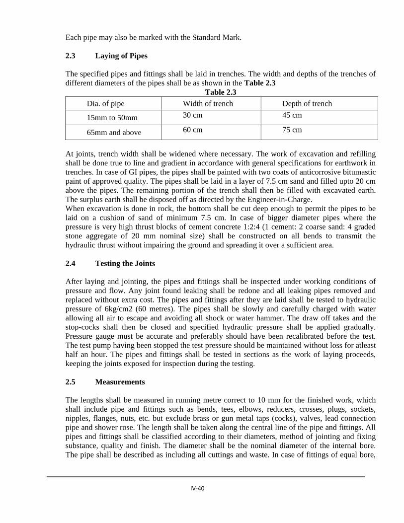
IV-40
Each pipe may also be marked with the Standard Mark.
2.3 Laying of Pipes
The specified pipes and fittings shall be laid in trenches. The width and depths of the trenches of
different diameters of the pipes shall be as shown in the Table 2.3
Table 2.3
Dia. of pipe Width of trench Depth of trench
15mm to 50mm 30 cm 45 cm
65mm and above 60 cm 75 cm
At joints, trench width shall be widened where necessary. The work of excavation and refilling
shall be done true to line and gradient in accordance with general specifications for earthwork in
trenches. In case of GI pipes, the pipes shall be painted with two coats of anticorrosive bitumastic
paint of approved quality. The pipes shall be laid in a layer of 7.5 cm sand and filled upto 20 cm
above the pipes. The remaining portion of the trench shall then be filled with excavated earth.
The surplus earth shall be disposed off as directed by the Engineer-in-Charge.
When excavation is done in rock, the bottom shall be cut deep enough to permit the pipes to be
laid on a cushion of sand of minimum 7.5 cm. In case of bigger diameter pipes where the
pressure is very high thrust blocks of cement concrete 1:2:4 (1 cement: 2 coarse sand: 4 graded
stone aggregate of 20 mm nominal size) shall be constructed on all bends to transmit the
hydraulic thrust without impairing the ground and spreading it over a sufficient area.
2.4 Testing the Joints
After laying and jointing, the pipes and fittings shall be inspected under working conditions of
pressure and flow. Any joint found leaking shall be redone and all leaking pipes removed and
replaced without extra cost. The pipes and fittings after they are laid shall be tested to hydraulic
pressure of 6kg/cm2 (60 metres). The pipes shall be slowly and carefully charged with water
allowing all air to escape and avoiding all shock or water hammer. The draw off takes and the
stop-cocks shall then be closed and specified hydraulic pressure shall be applied gradually.
Pressure gauge must be accurate and preferably should have been recalibrated before the test.
The test pump having been stopped the test pressure should be maintained without loss for atleast
half an hour. The pipes and fittings shall be tested in sections as the work of laying proceeds,
keeping the joints exposed for inspection during the testing.
2.5 Measurements
The lengths shall be measured in running metre correct to 10 mm for the finished work, which
shall include pipe and fittings such as bends, tees, elbows, reducers, crosses, plugs, sockets,
nipples, flanges, nuts, etc. but exclude brass or gun metal taps (cocks), valves, lead connection
pipe and shower rose. The length shall be taken along the central line of the pipe and fittings. All
pipes and fittings shall be classified according to their diameters, method of jointing and fixing
substance, quality and finish. The diameter shall be the nominal diameter of the internal bore.
The pipe shall be described as including all cuttings and waste. In case of fittings of equal bore,
IV-41
the largest bore shall be measured. Digging and refilling of trenches shall be measured
separately.
2.6 Rate
The rate shall include the cost of labour and material involved in all operations described above
(excluding the cost for excavation in trenches, refilling of trenches, painting of pipes and sand
filling all-round the pipes).
3.0 Ductile iron Pipe & fittings
Ductile Iron Pipe shall be of class K-9 with inside Cement Mortar lining as IS: 9329 -2000 where
as fittings for Ductile Iron Pipe shall be as per IS: 9523:2000. Cement lining shall have thickness
of 5mm.
All pipes specials and valves shall be of relevant Bureau of Indian Standard grade. These should
have IS certification mark.
Joint of Ductile Iron Pipe shall be push on type. Rubber gasket shall be of SBR quality and
satisfy Hardness and other criteria as specified in IS: 5382-1985
3.1 Excavation and Preparation of Trenches
The width of trench at the bottom between faces of sheeting shall be such as to provide not less
than 200mm clearance on either side of the pipe except where rock excavation is involved. In
agricultural land, the depth must not be less than 900mm, while it may be necessary to increase
the depth of pipeline in the vicinity of land drains, roads, railways and other crossings.
When pipes are directly bedded on the bottom of the trench, it should be trimmed and leveled,
and where excavation is through rocks or boulders, the pipeline should be bedded on concrete
bedding or on at least 150mm or fine grained soil or other means to protect the pipe and the
coating.
3.2 Back filling
For the purpose of back filling the depth of the trench shall be considered as divided into the
following three zone from the bottom of trench to its top.
Zone ‘A’: From the bottom of trench to the level of centre line of pipe.
Zone ‘B’: From the level of the centreline of pipe to a level 300 above the top of pipe.
Zone ‘C’: From a level 300 mm above the top of the pipe to the top of trench.

IV-42
3.2.1 Back fill Material
All backfill material shall be free from cinder, slag, refuse, rubbish vegetable or organic material,
lumpy or frozen material boulder rock or other stone, material which in the opinion of Engineer-
in-charge is unsuitable or deleterious. However, material containing stones upto 200 mm as their
greatest dimension may be used in zone ‘C’ unless otherwise specified herein.
3.2.2 Back fill sand
Sand used for back fill shall be natural sand complying above, graded form fine to coarse. The
total weight of loam or clay in it shall not exceed 10%. All material shall pass through a sieve of
aperture size 0.63mm.
3.2.3 Back – filling gravel
Gravel used for back fill shall be natural gravel complying criteria mentioned in above having
durable particle, graded from fine to course in a reasonable uniform combination with no boulder
or stone larger than 50 mm in size. It shall not contain excessive amount of loam and clay and
not more than 15% shall remain on a sieve of aperture size 75 micron.
Backfilling in zone ‘A’ shall be done by hand with sand, fine gravel or other approved material
placed in layer of 150mm and compacted by tamping. The back filling material shall be
deposited in trench for its full width of each side of the pipe filling and appurtenance
simultaneously.
Backfilling in Zone ‘B’ shall be done by hand or approved mechanical methods in layers of
150mm, special care being taken to avoid injuring or moving the pipe. The type of back fill
material to used and the method of placing and consolidating shall be prescribed by the Engineer-
in-charge to suit individual locations.
Back filling Zone ‘C’ shall be done by hand or approved mechanical methods the type of backfill
material and method of filling shall be as prescribed by the Engineer-in-charge.
3.3 Laying of pipes
3.3.1 Laying Underground
Pipes should be lowered into trench with tackle or rope suitable for the weight of pipe. All
construction debris should be cleared from the inside of pipe either before or just after joint is
made. This is done by passing a pull-through in the pipe or by hand depending upon the size of
the pipe. When laying in not in progress a temporary end closure should be securely fitted to the
open end of the pipeline.
On gradients of 1:15 or steeper, precautions should be taken to ensure that the spigot of the pipe
does not move into or out of the socket of the socket of the laid pipe during the jointing
operations. As soon as the joint assembly has been completed, the pipe should be held firmly in
position while the trench is backfilled over the barrel of the pipe. The backfill should be well
compacted.

IV-43
3.3.2 Laying above ground
The ground should be dressed to match the curvature of pipe shell for an arch length subtending
an angle of 1200 at the centre of the pipes. Alternatively, the pipeline should be laid either on
saddle, roller or rocker supports as specified by Engineer-in-charge. The pipes may be allowed to
rest on ground if the soil is non-aggressive.
3.3.3 Pipe support
Pipe supports shall be provided in such a manner that there should not be any deflection at joints,
here each pipe shall be well supported as shown in drawing. Pipes should be fixed to supports
with weld steel straps so that axial movement due to expansion or contraction resulting from
temperature fluctuation is taken up at individual joints in the pipeline. In addition, joints should
be assembled with the spigot end withdrawn 5 to 10 mm from the bottom of the socket to
accommodate these thermal movements.
3.3.4 Cutting of pipes
The cutting of pipe for inserting valves, fittings, etc, shall be done in a neat and workman like
manner without damage to the pipe or lining so as to leave a smooth end at right angles to the
axis of the pipe. Methods of cutting ductile iron pipe is explained as:
3.3.4.1 By Hacksaw
Hand or power operated hacksaw should be used without blades having teeth at a pitch of 1 mm.
3.3.4.2 By Manually Operated Wheel Cutter
If approved by Engineer-in-charge manually operated wheel cutter with wheel specifically
designed for use in ductile iron pipes may be used.
3.3.4.3 By Pipe Cutting Machine
Machines with cutter heads or abrasive wheels shall be used. Cutter head should have a front rake
angle of 70.
3.3.4.4 End Preparation of Cut Pipes for Jointing
The burr left after cutting should be trimmed off of light grinding or by filling.
3.4 Wrapping
When ductile iron pipes are to be laid in aggressive soils, the pipes should be wrapped externally
with protective coatings, such as bitumen or coaltar sheathing protective tapes or by loose
polythene sleeving, or in certain circumstances, concrete before laying. At joints, bends and
valves, precautions should be taken to provide sufficient overlaps of the wrapping sleeve so that
no pipeline is exposed to the aggressive soil.

IV-44
3.5 Anchorage
Pipe line should be securely anchored at dead ends ties, bends tapes and valve to resist thrust
arising from internal pressure. Concrete and earthwork shall be done as mentioned in
specification.
3.6 Joints
Joints between two pieces of ductile iron pipe shall be push on joint and joint between pipe and
valves shall be mechanical joints.
Spigot and socket flexible joint should be laid to permit angular deflection in direction and axial
movement to compensate for ground movement and thermal expansion and construction.
All points shall be thoroughly cleaned before jointing Spigot and socket shall be in true
alignment. Instructions of manufacture for jointing shall be strictly complied with.
The inside of sockets and the outside of spigots should be cleaned and wire brushed for a distance
if 150 mm to 225 mm. Gland and gaskets should be wiped clean and inspected for damage. A
gap should be left between the end of the spigot and back of the socket to accommodate such
movement.
3.7 Transportation Handling and Inspection
3.7.1 General
All precautions shall be taken while lowering the pipe to avoid the damage of pipe or coating
caused due to impact.
3.7.2 Transportation
Pipes should be loaded in such a way that they are secured and that movement should take place
on vehicle during transit.
The pipes should be loaded on vehicle in pyramid or straight sided formation. In case of pyramid
loading the pipe in bottom layer should be restrained by use of wooden wedge secured to vehicle
being loaded. The pyramid is to be formed by resting pipe between pan of pipe in preceding layer
with socket in layer reversed.
The pipes should be transported in such a way that there is no damage to protective coating and
brushing or no damage of jointing surfaces.
3.8 Offloading
Pipe shall be offloaded using nominal bore, skid timbers and ropes. The pipes should be lifted
smoothly without any jerking motion and pipe movement should be controlled by the use of
guide roper in order to prevent damage caused by pipes bumping together or against surrounding
objects.

IV-45
3.9 Stacking
Pipes shall be stacked in the manner specified in I.S code 12288: 1989. Special precautions shall
be taken for handling Bitumen – sheathed pipe. They should not be stacker but laid in single
layer supported on timber placed under uncoated portion of the spigots a socket.
3.10 HYDRAULIC TESTING
After a new pipeline is laid and jointed, testing shall be done for:
Mechanical soundness and leak tightness of pipes and fittings.
Leak tightness of joints; and
Soundness of any construction work, in particular that of the anchorages.
3.10.1 General
The completed pipeline may be tested either in one length or in sections; the length of section
depending upon:
a. Availability of suitable water,
b. Number of joints to be inspected, and
c. Difference in elevation between one part of the pipeline and another.
Where the joints are left uncovered until after testing, sufficient materials should be back filled
over the centre of each pipe to prevent movement under the pressure.
It is prudent to begin testing in comparatively short length of test section. Progressively as
experience is gained, lengths of about 1.5 km or more, are tested in one section, subject to
consideration of length of trench which can be left open in particular circumstances.
Each section should be properly sealed-off, preferably with special stop ends secured by adequate
temporary anchors. All permanent anchors should be in position and, if of concrete, should have
developed adequate strength before testing begins. The section under test should be filled with
water, taking care that all the air is displaced either through vents at the high points or by using a
pig or a sphere.
3.10.2 Test pressure
The test pressure to be applied should be not less than any of the following:
The maximum sustained operating pressure,
The maximum static pressure plus 5 N/mm2, and
The sum of the maximum sustained operating pressure (or the maximum static pressure) and the
maximum calculated surge pressure.
After filling, the pipeline should be pressurized to the specified operating pressure and left for a
period of time to achieve stable conditions.
IV-46
The length of this period of time depends on many factors such as slight movement of the
pipeline under pressure whether air is trapped in the pipeline has a concrete lining which absorbs
water.
The pipelines are then pressurized up to the full test pressure and the section under test
completely closed off. The test should be maintained for a period of not less than 10 minutes to
reveal any defects in the pipes, joints or anchorages.
The test pressure should be measured at the lowest point of the section under test or alternatively
an allowance should be made for the static head between the lowest point and the point of
measurement to ensure that the required test pressure is not exceeded at the lowest point.
In case of extreme temperature conditions, there may be a tendency of hydraulic pressure
building up inside the pipeline because of expansion of water during the high day time. This
should normally not be of any major concern as the joints and the pipes are manufactured to
resist a much high pressure. However, sufficient care should be taken to prevent floating bulging
of the pipeline because up of such high pressure during the temperature rise.
If the test is not satisfactory, the fault should be found and rectified. Where there is difficulty in
locating a fault, the section under test should be sub-divided and each part tested separately.
3.10.3 Methods employed for finding leaks
Visual inspection of each joint if, not covered by the backfill; Use of a bar probe to detect signs
of water in the vicinity of joints if backfilled; Aural inspection using a stethoscope or listening
stick in contact with the pipeline; Use of electronic listening device which detects and amplifies
the sound or vibrations due to escaping of water actual contact between the probe and the pipe is
not essential;
Injection of dye into the test water particularly suitable in water logged ground; and Introduction
of nitrous oxide in solution into the test water and using an infra- red gas connection indicator to
defect the presence of any nitrous oxide that has escaped through the leak.
After all Sections have been joined together on completion of section testing, a test on the
complete pipeline should be carried out. This test should be carried out at a pressure not less than
the maximum sustained operating pressure or the maximum sustained operating pressure or the
maximum sustained operating pressure or the maximum static pressure of the pipeline and during
the test, inspection made of all work which has not been subject to section tests. During the test,
the pressure at the lowest point in the pipeline should not exceed the maximum given in Table
3.1

IV-47
TABLE 3.1
MAXIMUM FIELD HYDROSTATIC TEST PRESSURE FOR DUCTILE IRON
PIPELINES WITH FLEXIBLE JOINTS
Nominal Bore in mm Maximum Field Hydrostatic Test Pressure in N/mm2
Upto 300 4.5
350 to 600 3.0
700 to 1200 2.1
Note 1-The above pressures are 0.5 N/mm2 higher than the pressure ratings for ductile iron pipes
and fitting with flexible joints. It is not considered necessary to field test ductile iron pipelines to
1 time the design operating pressure as is often the practice with grey iron pipelines.
Note 2- The field test pressure is applied to ductile iron pipelines only when the pipeline and its
fittings are properly anchored.
It is important to ensure that proper arrangements are made for the disposal of water from the
pipeline after completion of hydrostatic testing and that all consents which may be required from
authorities have been obtained. In some case, for example heavily chlorinated water, some
treatment may be necessary before final disposal.
4.0 FLUSHING AND DISINFECTION OF MAINS BEFORE COMMISSIONING
The mains intended for potable water supplies should be disinfected for commissioning them for
use.
4.1 Distribution System Chlorination of New Mains
Special care should be taken to ensure disinfection of new mains. Among possible sources of
contamination are sewer drainage, contaminated soil in the trench, contamination from workmen
and or their equipment and, unavoidable foreign material present in the trench during
construction.
All sewers, water mains and other underground conduits should be located prior to construction
and relocated, if necessary to prevent contamination during construction. Pipe should be stung on
high ground. At all times when construction is not actually in progress, watertight plugs should
be installed in all pipe openings. Gunny sacks and rags are not adequate. Provision should be
made to pump any other water that might have collected in the trench. Special care should be
taken to avoid contamination of valves, fittings, and pipe interiors both before and during
construction, each should be inspected and, if necessary, cleaned before installation.
After pressure testing the main, it should be flushed with water of sufficient velocity to remove
all dirt and other foreign materials. When this process has been completed, disinfection (using
liquid chlorine, sodium or calcium hypochlorine) is preceded by one of the recommended
methods as described.

IV-48
4.2 Continuous Feed
In this method, water from the distribution system or other approved source and the chlorine
from selected source are fed at constant rate into the new main at a concentration of at least 20 to
50 mg/litre. A properly adjusted hypochlorite solution injected into the main with a
hypochlorinator, or liquid chlorine injected into the main through a solution feed chlorinator and
booster pump may be used. The chlorine residual should be checked at intervals to ensure that
the proper level main is filled. All valves, hydrants, etc, along the main should be operated to
ensure their proper disinfection. The water should remain in the main for a minimum of 24
hours. Following the 24 hour period, no less than 10 mg/1 chlorine residual should remain in the
main.
4.3 Slug Method
In this method, a continuous flow of water is fed with a constant dose of chlorine with rates
proportioned to give a chlorine concentration of at least 300 mg/1. The chlorine isi applied
continuously for a period of time to provide a column of chlorinated water that will contact all
interior surfaces of the main for a period of at least three hours. As the slug passes, tecs, crosses,
etc, valves should be operated to ensure their disinfection. This method is used principally for
large diameter mains where continuous feed is impractical.
Regardless of the method used, it is necessary to make certain that backflow of the strong
chlorine solution into the supplying line does not occur. Following the prescribed contact period,
the chlorinated water should be flushed to waste until the remaining water has a chlorine residual
approximating that throughout the rest of the system. Bacteriological tests as prescribed by the
Engineer-in-charge should be taken, and if the results fail to meet minimum standards, the
disinfecting procedure should be repeated and the results again tested before placing the main in
service.
5.0 Manholes
5.1 Excavation
The manhole shall be excavated true to dimensions and levels shown on the plans or as directed
by the Engineer-in-Charge.
5.2 Bed Concrete
The manhole shall be built on a bed of cement concrete 1:4:8 (1 cement: 4 coarse sand: 8 graded
stone aggregate 40 mm nominal size) unless required by local authorities. The thickness of the
bed concrete shall be 20 cm for manholes upto 4.25 m depth and 30 cm for depths beyond 4.25 m
unless otherwise specified or directed by the Engineer–in-Charge. In bad ground, special
foundations as suitable shall be provided.

IV-49
5.3 Brick Work
The brickwork shall be with bricks in cement mortar 1:3 (1 cement: 3 fine sand). The external
joints of the brick masonry shall be finished smooth, and the joints of the pipes with the masonry
shall be made perfectly leak proof. The walls shall be built of one brick thickness for depths upto
4.25 m. Below the depth of 4.25 m in ordinary subsoil the wall thickness shall be increased to
one and half brick and at 9.75 m below ground two brick thick walls shall be built.
5.4 Plastering & pointing
The walls of the manholes shall be plastered inside with 12 mm thick cement plaster 1:3 (1
cement: 3 coarse sand) finished smooth. Where the saturated soil is met with also the external
surface of the walls of the manholes shall be plastered with 12 mm thick cement plaster 1:3 (1
cement: 3 coarse sand) finished smooth upto 30 cm above the highest sub-soil water level. The
plaster shall further be water proofed with addition of approved water proofing compound in a
quantity as per manufacturer’s specifications. For earthwork excavation, bed concrete, bed
concrete brickwork, plaster and pointing, R.C.C work and refilling of earth, respective
specifications shall be followed.
5.5 Benching
The channels and benching shall be done in cement concrete 1:2:4 (1 cement: 2 coarse sand: 4
graded stone aggregate 20 mm nominal size) and rendered smooth with neat cement. The depth
of channels and benching shall be as given below.
Size of drain Top of channel at the centre
above bed concrete
Depth of benching at side walls
above bed concrete
mm cm cm
100 15 20
150 20 30
200 25 35
250 30 40
300 35 45
350 40 50
400 45 55
450 50 60
5.6 Foot Rests
All manholes deeper than 0.8 m shall be provided with M.S. footrests. These shall be embedded
20 cm deep with 20 x 20 x 10 cm blocks of cement concrete 1:3:6 (1 cement: 3 coarse sand: 6
graded stone aggregate 20 mm nominal size). The block with M.S. foot rest placed in its centre
shall be cast in-situ along with the masonry and surface finished with 12 mm thick cement plaster
1:3 (1 cement: 3 coarse sand) finished smooth. Footrests shall be fixed 30 cm apart vertically and
staggered laterally and shall project 10 cm beyond the surface of the wall. The top footrest shall

IV-50
be 45 cm below the manhole cover. Foot rests shall be painted with coal tar, the portion
embedded in the masonry or cement concrete block being painted with thick cement slurry before
fixing.
5.7 Manhole Covers and Frames
The frame of manhole shall be firmly embedded to correct alignment and levels in 150mm th.
R.C.C slab (1:1.5:3) on the top of the masonry. The specified cover and frame shall be fixed.
After completion of the work, manhole covers shall be sealed by means of thick grease.
5.8 Measurements
Manholes shall be measured in numbers under relevant items. The depth of the manhole shall be
reckoned from the top level of C.I. cover to the invert level of channel. The depth shall be
measured correct to a cm. The extra depth shall be measured and paid as extra over the specified
depth.
5.9 Rate
The rate shall include the cost of materials and labour involved in all the operations described
above but exclude the cost of M.S. foot rests and 12 mm thick cement plaster with water proofing
material applied at the external surface of the manhole if required. These items shall be paid for
separately under relevant items of work.
Payment for extra depth of manholes shall be made separately under relevant item of work.
6.0 Fire Hydrants
The hydrants shall be controlled by a cast iron valve/butterfly valves. Hydrants shall have
instantaneous type 63 mm dia outlets. The hydrants shall be of gunmetal and flange inlet and
single outlet conforming to I.S 5290-1975 with G.I duck foot bend and flanged riser of required
height to bring the hydrant to correct level above ground.
Contractor shall provide for each external fire hydrant two nos. of 63 mm dia. 15 meter long
Hose pipe with gunmetal male and female instantaneous type couplings machine would with
copper wire hose to IS 636 type A and couplings to IS 903 with IS certification ), gunmetal
branch pipe with 16 mm nozzle to IS 903 as shown on the drawings/BOQ
7.0 Removal, restoration and maintenance of paved footpaths, etc, after laying of pipe
7.1 Allowable Removal of Pavement
Pavement and road surfaces may be removed as a part of the trench excavation, and the amount
removed shall depend upon the width of trench specified for the installation of the pipe and the
width and length of the pavement area required to be removed for the installation of gate valves,
specials, manholes or other structures. The width of pavement removed along the normal trench
for the installation of the pipe shall not exceed the width of the trench specified by more than 150
mm on each side of trench. The width and the lengths of the area of pavement removed from the
installation of gate valves, specials, manholes or other structures should not exceed the maximum
IV-51
linear dimensions of such structures by more than 150 mm on each side. Wherever, in the
opinion of the Engineer-in-charge, existing conditions make it necessary or advisable to remove
additional pavement, it shall be removed as directed by the Engineer-in-charge.
7.2 Restoration of Damaged Surface and Property
Where any pavement, shrubbery, fences poles or other property and surface structure have been
damaged, removed or disturbed during the course of work, such property and surface structures
shall be replaced or repaired after completion of work. All pavements, paved for paths, curbing,
gutters, shrubbery, fences, poles sod or other property and surface, structures removed or
disturbed as a part of the work shall be restored to a condition equal to that before the work
began, furnishing all labour and materials incidental thereto. In restoring the pavement, sound
stone blocks, sound brick or asphalt pavement shall be restored unless and untill, in the opinion
of the authority, the condition of the backfill is such as to property support the pavement.
7.3 Cleaning up
All surplus materials, and all tools and temporary structures shall be removed from the site as directed
by the authority. All dirt, rubbish and excess earth from the excavation shall be hauled to a dump and
the construction site left dam