
Pixel Control System - Elevator...
101
All information contained herein is confidential and proprietary to Elevator Controls Corporation. This document shall not be used or reproduced, in whole or part, without the prior written consent of Elevator Controls. Pub ID: Pixel-Hydro-Man- Rev 04-10-17 © 2013 Elevator Controls Corporation Product Documentation that‟s Simple to Navigate TM This is the Installation and Adjustment Manual that is the guide for installation, startup and final adjustment of all Pixel Hydraulic Series elevator controllers. Other resources include: Solid State Starter Motor Control Specific Manuals Maintenance & Troubleshooting Training Manual provided in conjunction with Factory and Customer Site technical training classes Telephone Technical Support available for Customers at no charge call: 916/428-1708 e-mail: [email protected] fax: 916/428-1728 Onsite Product & Engineering Support available worldwide by prior arrangement. Pixel Control System Installation & Adjustment For Hydraulic Elevator Applications Utilizing Mechanical or Solid State Starter Motor Control
Transcript of Pixel Control System - Elevator...
All information contained herein is confidential and proprietary to Elevator Controls Corporation. This document shall not be used or reproduced,
in whole or part, without the prior written consent of Elevator Controls.
Pub ID: Pixel-Hydro-Man- Rev 04-10-17
© 2013 Elevator Controls Corporation
Product Documentation that‟s Simple to NavigateTM
This is the Installation and Adjustment Manual that is the guide for installation, startup and final adjustment of all Pixel Hydraulic Series elevator controllers. Other resources include:
Solid State Starter Motor Control Specific Manuals
Maintenance & Troubleshooting Training Manual provided in conjunction with Factory and Customer Site technical training classes
Telephone Technical Support available for Customers at no charge
call: 916/428-1708
e-mail: [email protected]
fax: 916/428-1728
Onsite Product & Engineering Support available worldwide by prior arrangement.
Pixel Control System Installation & Adjustment
For Hydraulic Elevator Applications Utilizing Mechanical or Solid State Starter Motor Control
EC Pixel Hydraulic Controller Installation & Adjustment Manual ii
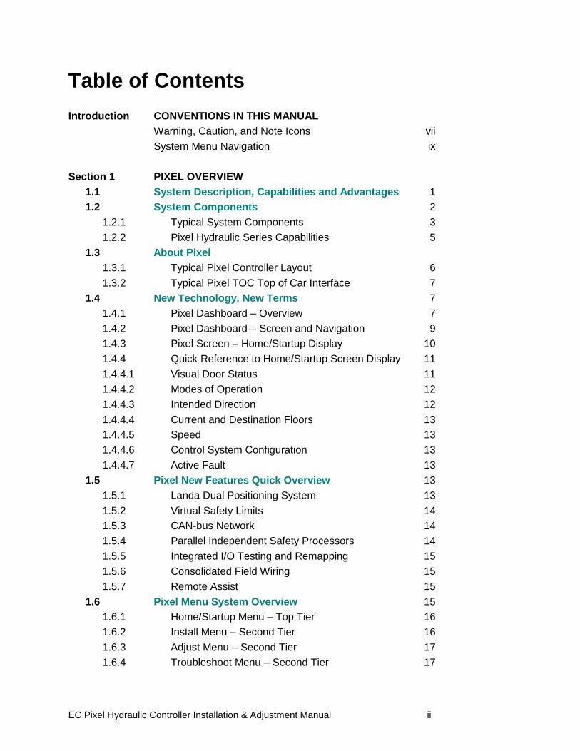
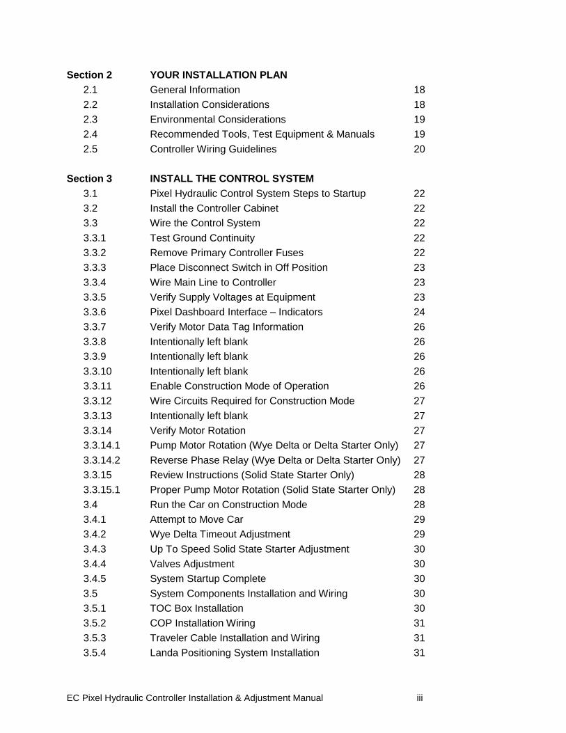
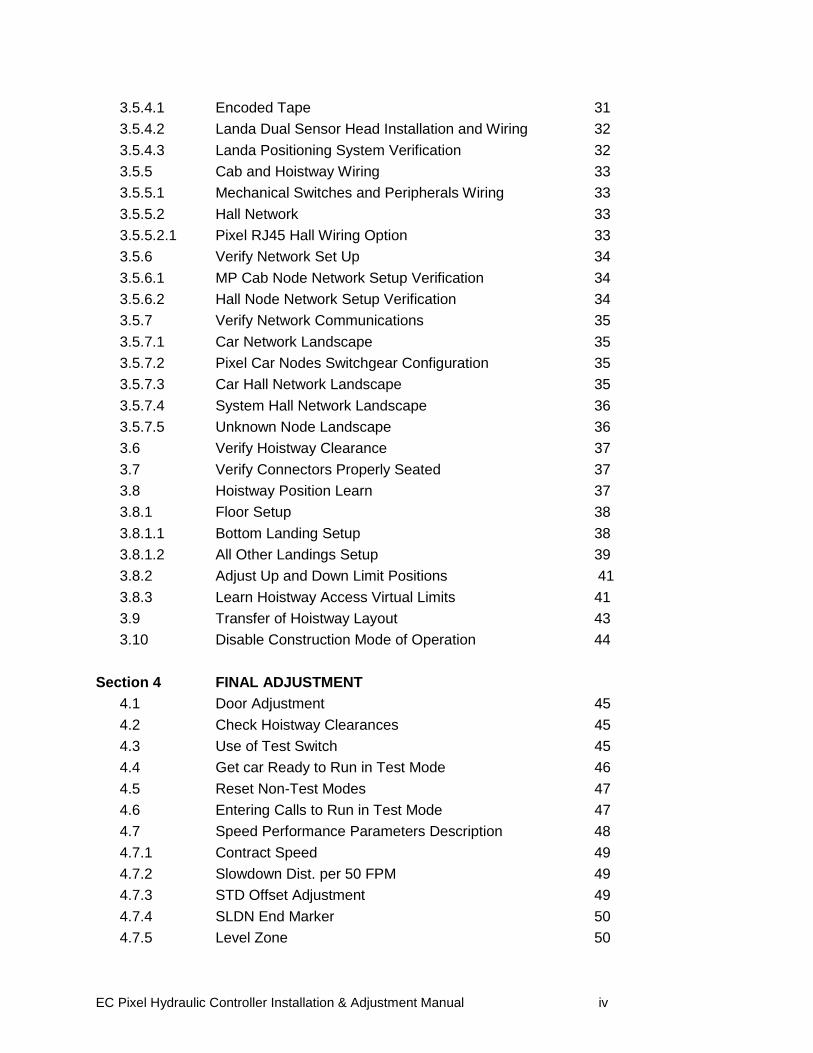
Table of Contents
Introduction CONVENTIONS IN THIS MANUAL
Warning, Caution, and Note Icons vii
System Menu Navigation ix
Section 1 PIXEL OVERVIEW
1.1 System Description, Capabilities and Advantages 1
1.2 System Components 2
1.2.1 Typical System Components 3
1.2.2 Pixel Hydraulic Series Capabilities 5
1.3 About Pixel
1.3.1 Typical Pixel Controller Layout 6
1.3.2 Typical Pixel TOC Top of Car Interface 7
1.4 New Technology, New Terms 7
1.4.1 Pixel Dashboard – Overview 7
1.4.2 Pixel Dashboard – Screen and Navigation 9
1.4.3 Pixel Screen – Home/Startup Display 10
1.4.4 Quick Reference to Home/Startup Screen Display 11
1.4.4.1 Visual Door Status 11
1.4.4.2 Modes of Operation 12
1.4.4.3 Intended Direction 12
1.4.4.4 Current and Destination Floors 13
1.4.4.5 Speed 13
1.4.4.6 Control System Configuration 13
1.4.4.7 Active Fault 13
1.5 Pixel New Features Quick Overview 13
1.5.1 Landa Dual Positioning System 13
1.5.2 Virtual Safety Limits 14
1.5.3 CAN-bus Network 14
1.5.4 Parallel Independent Safety Processors 14
1.5.5 Integrated I/O Testing and Remapping 15
1.5.6 Consolidated Field Wiring 15
1.5.7 Remote Assist 15
1.6 Pixel Menu System Overview 15
1.6.1 Home/Startup Menu – Top Tier 16
1.6.2 Install Menu – Second Tier 16
1.6.3 Adjust Menu – Second Tier 17
1.6.4 Troubleshoot Menu – Second Tier 17
EC Pixel Hydraulic Controller Installation & Adjustment Manual iii
Section 2 YOUR INSTALLATION PLAN
2.1 General Information 18
2.2 Installation Considerations 18
2.3 Environmental Considerations 19
2.4 Recommended Tools, Test Equipment & Manuals 19
2.5 Controller Wiring Guidelines 20
Section 3 INSTALL THE CONTROL SYSTEM
3.1 Pixel Hydraulic Control System Steps to Startup 22
3.2 Install the Controller Cabinet 22
3.3 Wire the Control System 22
3.3.1 Test Ground Continuity 22
3.3.2 Remove Primary Controller Fuses 22
3.3.3 Place Disconnect Switch in Off Position 23
3.3.4 Wire Main Line to Controller 23
3.3.5 Verify Supply Voltages at Equipment 23
3.3.6 Pixel Dashboard Interface – Indicators 24
3.3.7 Verify Motor Data Tag Information 26
3.3.8 Intentionally left blank 26
3.3.9 Intentionally left blank 26
3.3.10 Intentionally left blank 26
3.3.11 Enable Construction Mode of Operation 26
3.3.12 Wire Circuits Required for Construction Mode 27
3.3.13 Intentionally left blank 27
3.3.14 Verify Motor Rotation 27
3.3.14.1 Pump Motor Rotation (Wye Delta or Delta Starter Only) 27
3.3.14.2 Reverse Phase Relay (Wye Delta or Delta Starter Only) 27
3.3.15 Review Instructions (Solid State Starter Only) 28
3.3.15.1 Proper Pump Motor Rotation (Solid State Starter Only) 28
3.4 Run the Car on Construction Mode 28
3.4.1 Attempt to Move Car 29
3.4.2 Wye Delta Timeout Adjustment 29
3.4.3 Up To Speed Solid State Starter Adjustment 30
3.4.4 Valves Adjustment 30
3.4.5 System Startup Complete 30
3.5 System Components Installation and Wiring 30
3.5.1 TOC Box Installation 30
3.5.2 COP Installation Wiring 31
3.5.3 Traveler Cable Installation and Wiring 31
3.5.4 Landa Positioning System Installation 31
EC Pixel Hydraulic Controller Installation & Adjustment Manual iv
3.5.4.1 Encoded Tape 31
3.5.4.2 Landa Dual Sensor Head Installation and Wiring 32
3.5.4.3 Landa Positioning System Verification 32
3.5.5 Cab and Hoistway Wiring 33
3.5.5.1 Mechanical Switches and Peripherals Wiring 33
3.5.5.2 Hall Network 33
3.5.5.2.1 Pixel RJ45 Hall Wiring Option 33
3.5.6 Verify Network Set Up 34
3.5.6.1 MP Cab Node Network Setup Verification 34
3.5.6.2 Hall Node Network Setup Verification 34
3.5.7 Verify Network Communications 35
3.5.7.1 Car Network Landscape 35
3.5.7.2 Pixel Car Nodes Switchgear Configuration 35
3.5.7.3 Car Hall Network Landscape 35
3.5.7.4 System Hall Network Landscape 36
3.5.7.5 Unknown Node Landscape 36
3.6 Verify Hoistway Clearance 37
3.7 Verify Connectors Properly Seated 37
3.8 Hoistway Position Learn 37
3.8.1 Floor Setup 38
3.8.1.1 Bottom Landing Setup 38
3.8.1.2 All Other Landings Setup 39
3.8.2 Adjust Up and Down Limit Positions 41
3.8.3 Learn Hoistway Access Virtual Limits 41
3.9 Transfer of Hoistway Layout 43
3.10 Disable Construction Mode of Operation 44
Section 4 FINAL ADJUSTMENT
4.1 Door Adjustment 45
4.2 Check Hoistway Clearances 45
4.3 Use of Test Switch 45
4.4 Get car Ready to Run in Test Mode 46
4.5 Reset Non-Test Modes 47
4.6 Entering Calls to Run in Test Mode 47
4.7 Speed Performance Parameters Description 48
4.7.1 Contract Speed 49
4.7.2 Slowdown Dist. per 50 FPM 49
4.7.3 STD Offset Adjustment 49
4.7.4 SLDN End Marker 50
4.7.5 Level Zone 50
EC Pixel Hydraulic Controller Installation & Adjustment Manual v
4.7.6 Dead Zone 50
4.7.7 Leveling Adjustment 51
4.7.8 Highspeed Trip Speed 51
4.7.9 Inspection Trip Speed 51
4.7.10 Leveling Trip Speed 52
4.7.11 Terminals % Trip Speed 52
4.7.12 High Speed on Inspection 53
4.7.13 Releveing Up Offset 53
4.8 Verify Speed Parameters 54
4.8.1 Verify Short Floor Distance 54
4.8.2 Verify Speed Parameters 55
4.9 Run Car to Every landing 56
4.9.1 Slowdown Distance per 50FPM Adjustment 56
4.9.2 STD Offset Adjustment 56
4.10 Pump Motor Soft Stop 56
4.11 Adjust Leveling Adjustment 57
4.12 Adjust Releveling Offset 57
4.13 Adjust Floor Levels 57
4.14 ETS Learn 59
4.15 Transfer Safety Configuration File 59
4.16 Verify Overall Car Performance 60
Section 5 SPEED MONITORING ADJUSTMENT
5.1 Car Speed Monitoring System 61
5.1.1 Defining Overspeed 61
5.1.2 Monitoring Overspeed 62
5.1.3 Speed Monitoring Adjustment 62
Section 6 CODE COMPLIANCE VERIFICATION
6.1 Performing Elevator Safety Tests & Inspections 64
6.2 Intentionally Left Blank 64
6.3 Intentionally Left Blank 64
6.4 Safety Speed Tests 64
6.4.1 Car Buffer Test – Fully Loaded Car 64
6.4.2 Intentionally Left Blank 65
6.4.3 Intentionally Left Blank 65
6.4.4 Terminal Stopping Devices (A17.1 Section 3.25) 66
6.4.4.1 Terminal Speed Reducing Devices 66
6.4.4.2 Normal Terminal Stopping Devices 67
6.5 Overspeed Tests 68
EC Pixel Hydraulic Controller Installation & Adjustment Manual vi
6.5.1 Inspection Overspeed 68
6.5.2 Leveling Overspeed 69
6.5.3 Intentionally Left Blank 70
6.5.4 Contract Overspeed 70
6.6 Valve High Pressure Relief (The Stop Ring Test) 71
6.7 Intentionally Left Blank 72
6.8 Landa Redundant Position System Verification 72
6.9 Monitoring Compliance Verification 74
6.9.1 EB1-EBS and EBX1-EBX2 Relays Contacts 74
6.9.2 AA Motor Contactor Force Guided Relay 75
6.9.3 P Potential Force Guided Relay 76
6.9.4 BK Relay 77
6.9.5 Hoistway & Car Door Bypass Switches 78
6.9.6 Detection of Jumpers on Door Safety String 80
6.9.7 Door Open and Close Simultaneously 81
6.9.8 Valves Latched Direction 82
6.9.8.1 U Relay Contact 1 82
6.9.8.2 D Relay Contact 1 83
6.9.9 Single Ground 84
6.9.10 Permit Car Speeds Over 150 fpm 84
Section 7 TROUBLESHOOTING
7.1 General Troubleshooting Tips 85
7.2 General Checklist 85
7.3 Fault Help Menu Navigation Example 86
7.3.1 Troubleshooting Example 86
Section 8 Section intentionally left blank 89
Section 9 MAINTENANCE
9.1 Maintenance 90
9.2 Replacement Parts List 90
9.2.1 Elevator Controls PC Boards 90
9.2.2 Relays 90
9.2.3 Fuses 91
9.2.4 Modules 91
9.2.5 Semiconductors 91
EC Pixel Hydraulic Controller Installation & Adjustment Manual vii
Introduction Conventions in this Manual
Warning, Caution, and Note Icons
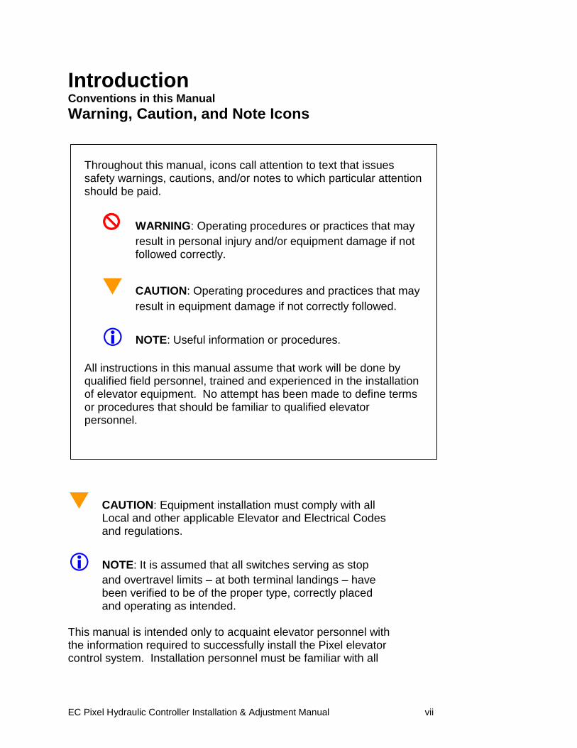
CAUTION: Equipment installation must comply with all Local and other applicable Elevator and Electrical Codes and regulations.
NOTE: It is assumed that all switches serving as stop
and overtravel limits – at both terminal landings – have been verified to be of the proper type, correctly placed and operating as intended.
This manual is intended only to acquaint elevator personnel with the information required to successfully install the Pixel elevator control system. Installation personnel must be familiar with all
Throughout this manual, icons call attention to text that issues safety warnings, cautions, and/or notes to which particular attention should be paid.
WARNING: Operating procedures or practices that may
result in personal injury and/or equipment damage if not followed correctly.
CAUTION: Operating procedures and practices that may
result in equipment damage if not correctly followed.
NOTE: Useful information or procedures.
All instructions in this manual assume that work will be done by qualified field personnel, trained and experienced in the installation of elevator equipment. No attempt has been made to define terms or procedures that should be familiar to qualified elevator personnel.
EC Pixel Hydraulic Controller Installation & Adjustment Manual viii
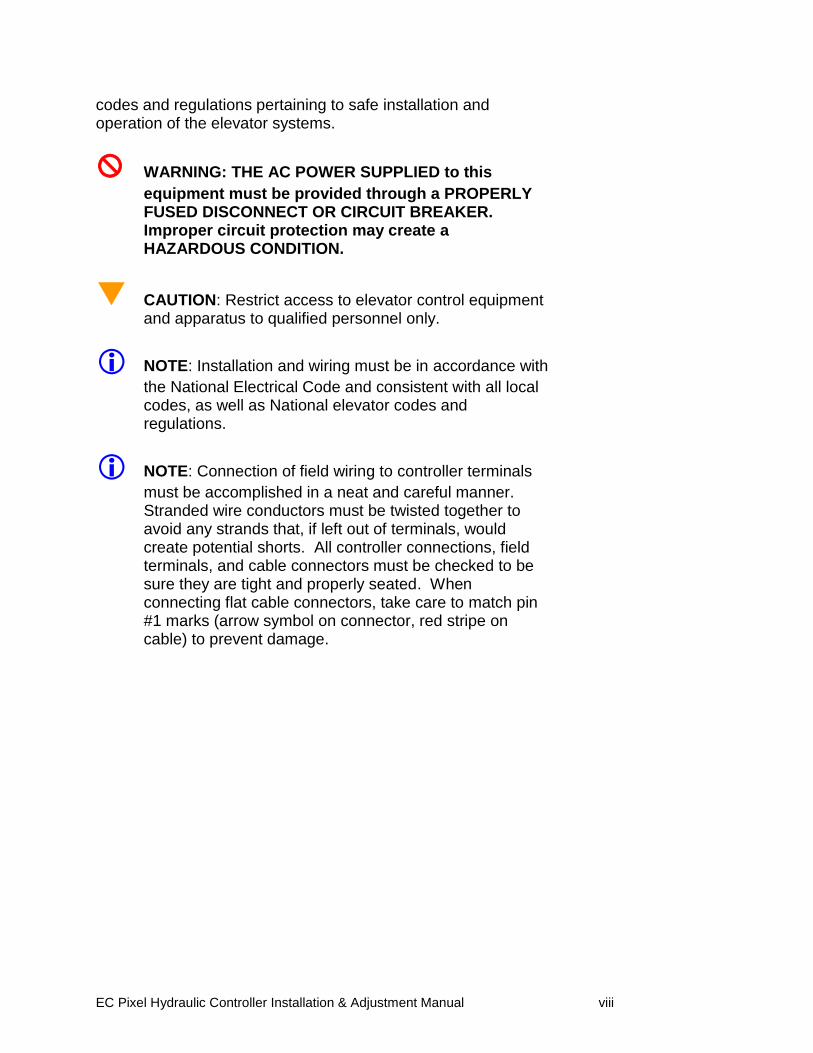
codes and regulations pertaining to safe installation and operation of the elevator systems.
WARNING: THE AC POWER SUPPLIED to this
equipment must be provided through a PROPERLY FUSED DISCONNECT OR CIRCUIT BREAKER. Improper circuit protection may create a HAZARDOUS CONDITION.
CAUTION: Restrict access to elevator control equipment and apparatus to qualified personnel only.
NOTE: Installation and wiring must be in accordance with
the National Electrical Code and consistent with all local codes, as well as National elevator codes and regulations.
NOTE: Connection of field wiring to controller terminals
must be accomplished in a neat and careful manner. Stranded wire conductors must be twisted together to avoid any strands that, if left out of terminals, would create potential shorts. All controller connections, field terminals, and cable connectors must be checked to be sure they are tight and properly seated. When connecting flat cable connectors, take care to match pin #1 marks (arrow symbol on connector, red stripe on cable) to prevent damage.
EC Pixel Hydraulic Controller Installation & Adjustment Manual ix
Conventions in this Manual
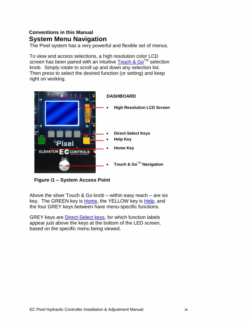
System Menu Navigation The Pixel system has a very powerful and flexible set of menus.
To view and access selections, a high resolution color LCD screen has been paired with an intuitive Touch & GoTM selection knob. Simply rotate to scroll up and down any selection list. Then press to select the desired function (or setting) and keep right on working.
Above the silver Touch & Go knob – within easy reach – are six key. The GREEN key is Home, the YELLOW key is Help, and the four GREY keys between have menu-specific functions.
GREY keys are Direct-Select keys, for which function labels appear just above the keys at the bottom of the LED screen, based on the specific menu being viewed.
DASHBOARD
High Resolution LCD Screen
Direct-Select Keys
Help Key
Home Key
Touch & GoTM
Navigation
Figure i1 – System Access Point
EC Pixel Hydraulic Controller Installation & Adjustment Manual x
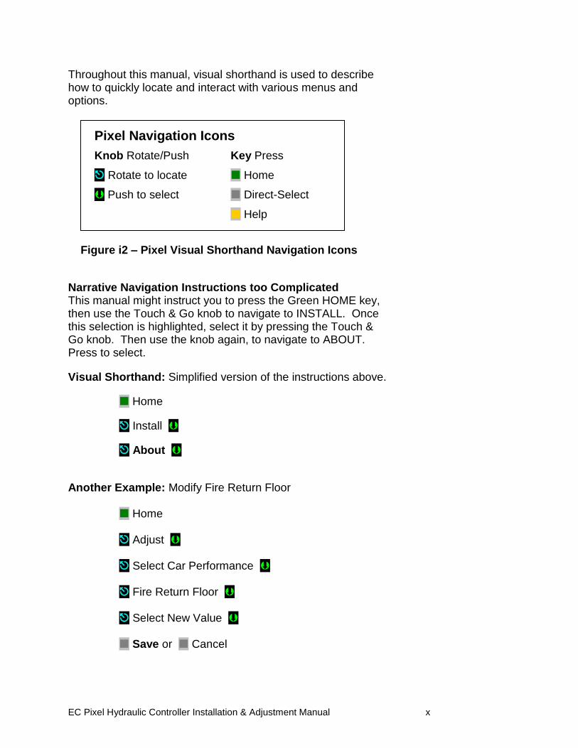
Throughout this manual, visual shorthand is used to describe how to quickly locate and interact with various menus and options.
Narrative Navigation Instructions too Complicated This manual might instruct you to press the Green HOME key, then use the Touch & Go knob to navigate to INSTALL. Once this selection is highlighted, select it by pressing the Touch & Go knob. Then use the knob again, to navigate to ABOUT. Press to select.
Visual Shorthand: Simplified version of the instructions above.
Home
Install
About
Another Example: Modify Fire Return Floor Home Adjust Select Car Performance Fire Return Floor Select New Value Save or Cancel
Pixel Navigation Icons
Knob Rotate/Push Key Press
Rotate to locate Home
Push to select Direct-Select
Help
Figure i2 – Pixel Visual Shorthand Navigation Icons

EC Pixel Hydraulic Controller Installation & Adjustment Manual 1
Section 1 – Pixel Overview 1.1 System Description, Capabilities & Advantages
The Pixel Hydraulic Control System uses advanced technology to enable more routine tasks to be accomplished faster.
Everything about Pixel has been designed to save field labor time. This digital elevator control system provides three points of system access – Machine Room, Cartop, and Inside the Cab – so the most convenient location can be used to complete tasks quickly and easily. Each of the three system access points includes a vivid color LCD display, unique Touch & GoTM interface, one-button access to context-responsive help, and intuitive direct-select keys. Instant real-time awareness of current car operation is provided on all displays when not otherwise in use. The LandaTM car positioning system provides absolute cab position information with high tech accuracy – using dual sensor heads to track cab position to 0.8 millimeter. Landa components are mounted quickly – all limits, slowdowns and landings are defined virtually, stored digitally, and easily readjusted. No need to install or wire vanes or switches in the hoistway (except top physical limit switch as required by elevator safety code). Powerful yet simplified diagnostics are built into each system access point, including the ability to intuitively view and easily reprogram elevator “personality” parameters onsite. Review and adjust parameters, access fault diagnostics and playback the operating sequence leading to a fault notification. The integrated Pixel control system package typically includes the car controller, cartop box with access point, COP access point, Landa positioning system, and hall nodes that communicate using EC‟s enhanced c-LINKTM CAN-bus serial communication system. c-LINK reduces wire count for hall, car and cartop signals without compromising EC‟s Safe & SensibleTM standards. Dual CAN-bus controller area networks provide high speed internal system communication. Use of this industrial standard communication protocol opens the door to interoperability with a variety of current and future products and peripherals – including the latest door operators. Overall reliability is enhanced by surface-mount electronic components, large scale integrated circuits, and state-of-the-art PC boards.
EC Pixel Hydraulic Controller Installation & Adjustment Manual 2
When the power of technology is used to simplify essential tasks – including installation, adjustment, maintenance and troubleshooting – everybody wins.
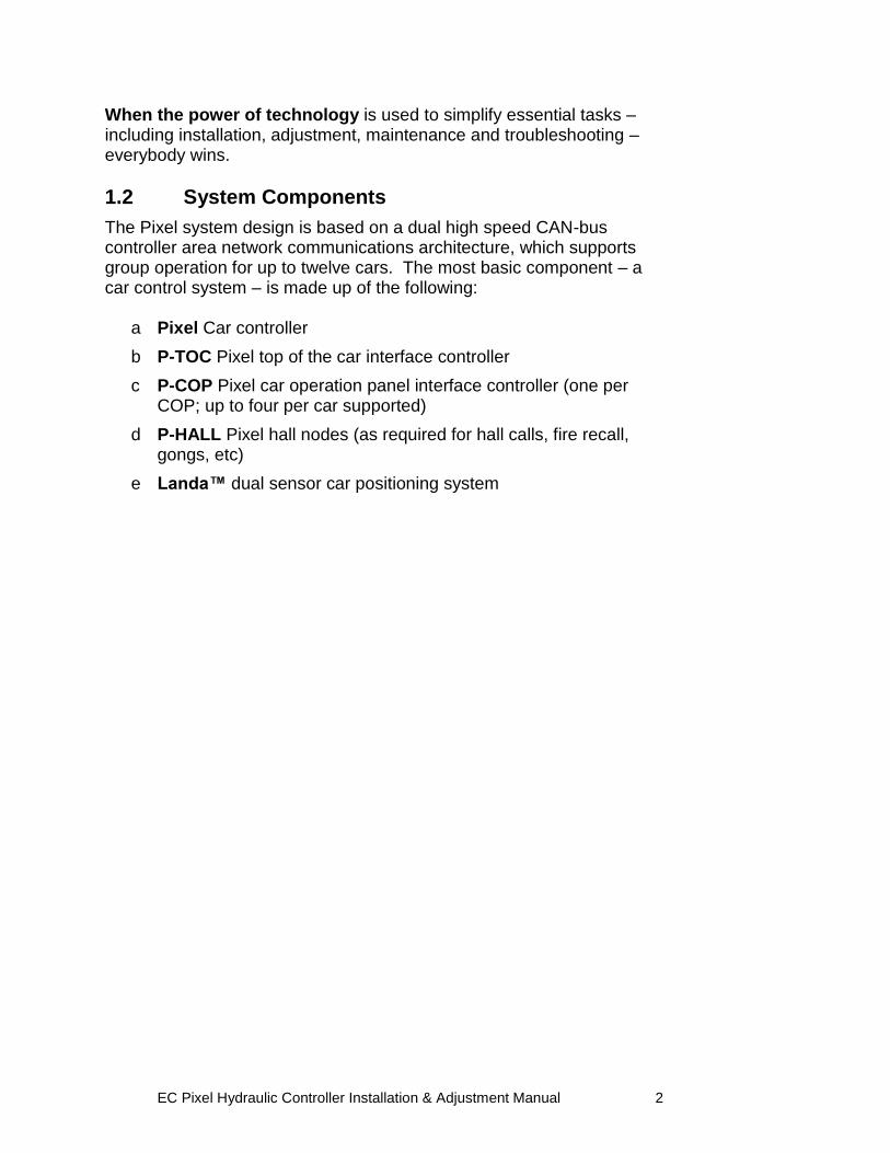
1.2 System Components
The Pixel system design is based on a dual high speed CAN-bus controller area network communications architecture, which supports group operation for up to twelve cars. The most basic component – a car control system – is made up of the following:
a Pixel Car controller
b P-TOC Pixel top of the car interface controller
c P-COP Pixel car operation panel interface controller (one per COP; up to four per car supported)
d P-HALL Pixel hall nodes (as required for hall calls, fire recall, gongs, etc)
e Landa™ dual sensor car positioning system
EC Pixel Hydraulic Controller Installation & Adjustment Manual 3
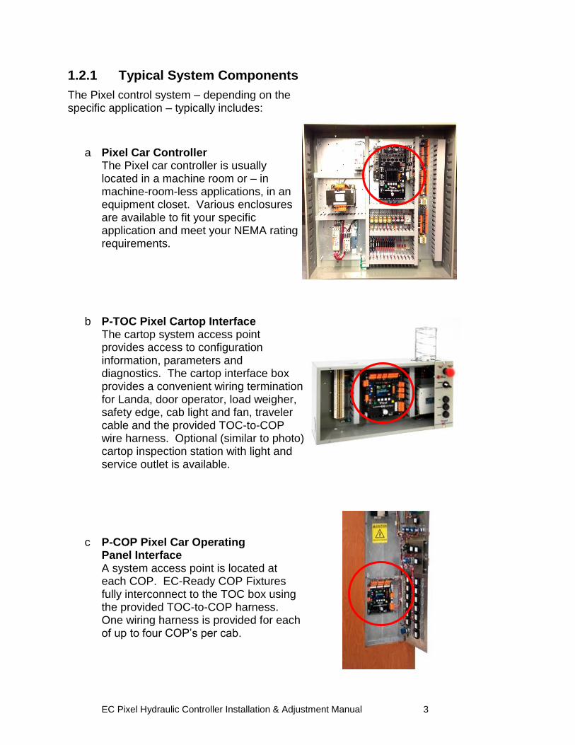
1.2.1 Typical System Components
The Pixel control system – depending on the specific application – typically includes:
a Pixel Car Controller
The Pixel car controller is usually located in a machine room or – in machine-room-less applications, in an equipment closet. Various enclosures are available to fit your specific application and meet your NEMA rating requirements.
b P-TOC Pixel Cartop Interface The cartop system access point provides access to configuration information, parameters and diagnostics. The cartop interface box provides a convenient wiring termination for Landa, door operator, load weigher, safety edge, cab light and fan, traveler cable and the provided TOC-to-COP wire harness. Optional (similar to photo) cartop inspection station with light and service outlet is available.
c P-COP Pixel Car Operating Panel Interface A system access point is located at each COP. EC-Ready COP Fixtures fully interconnect to the TOC box using the provided TOC-to-COP harness. One wiring harness is provided for each of up to four COP‟s per cab.
EC Pixel Hydraulic Controller Installation & Adjustment Manual 4
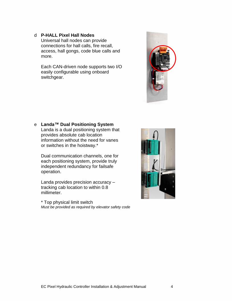
d P-HALL Pixel Hall Nodes
Universal hall nodes can provide connections for hall calls, fire recall, access, hall gongs, code blue calls and more. Each CAN-driven node supports two I/O easily configurable using onboard switchgear.
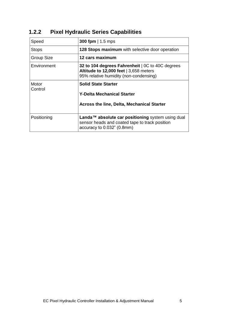
e Landa™ Dual Positioning System
Landa is a dual positioning system that provides absolute cab location information without the need for vanes or switches in the hoistway.* Dual communication channels, one for each positioning system, provide truly independent redundancy for failsafe operation. Landa provides precision accuracy – tracking cab location to within 0.8 millimeter.
* Top physical limit switch Must be provided as required by elevator safety code
EC Pixel Hydraulic Controller Installation & Adjustment Manual 5
1.2.2 Pixel Hydraulic Series Capabilities
Speed 300 fpm | 1.5 mps
Stops 128 Stops maximum with selective door operation
Group Size 12 cars maximum
Environment 32 to 104 degrees Fahrenheit | 0C to 40C degrees Altitude to 12,000 feet | 3,658 meters 95% relative humidity (non-condensing)
Motor Control
Solid State Starter Y-Delta Mechanical Starter Across the line, Delta, Mechanical Starter
Positioning Landa™ absolute car positioning system using dual sensor heads and coated tape to track position accuracy to 0.032” (0.8mm)
EC Pixel Hydraulic Controller Installation & Adjustment Manual 6
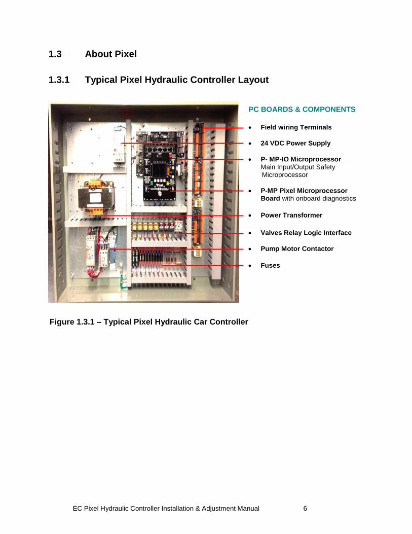
Figure 1.3.1 – Typical Pixel Hydraulic Car Controller
1.3 About Pixel
1.3.1 Typical Pixel Hydraulic Controller Layout
PC BOARDS & COMPONENTS
Field wiring Terminals
24 VDC Power Supply
P- MP-IO Microprocessor Main Input/Output Safety Microprocessor
P-MP Pixel Microprocessor Board with onboard diagnostics
Power Transformer
Valves Relay Logic Interface
Pump Motor Contactor
Fuses
EC Pixel Hydraulic Controller Installation & Adjustment Manual 7
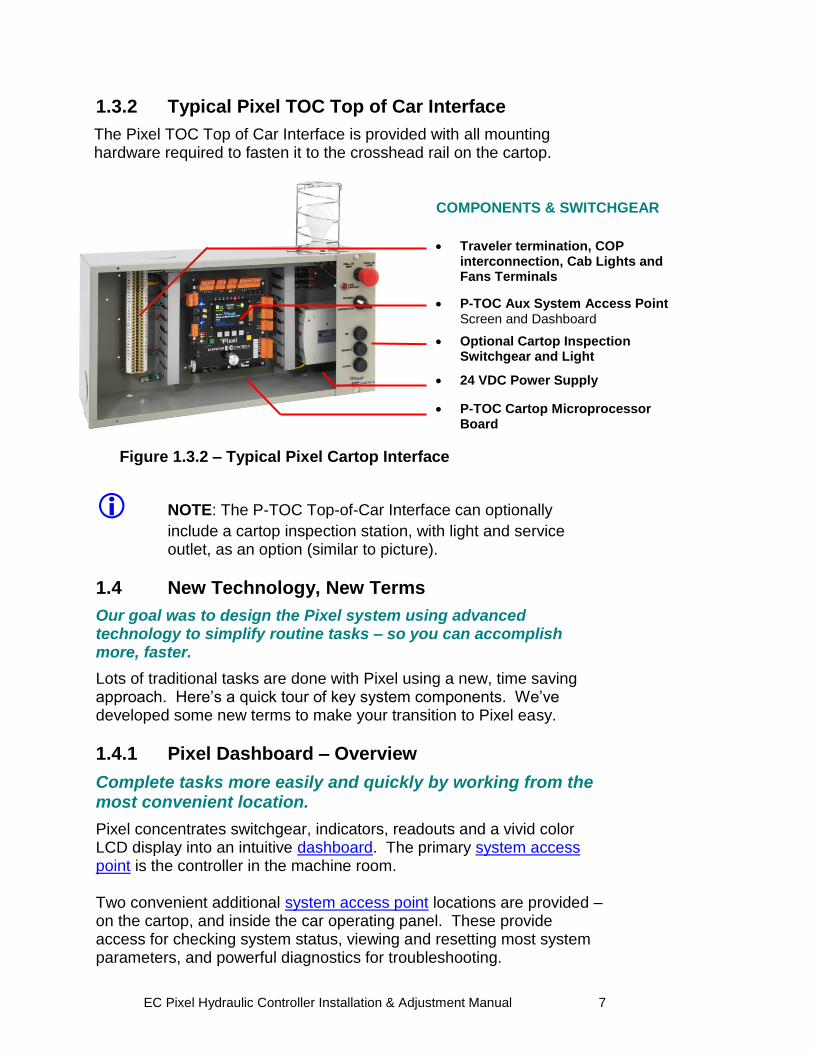
1.3.2 Typical Pixel TOC Top of Car Interface
The Pixel TOC Top of Car Interface is provided with all mounting hardware required to fasten it to the crosshead rail on the cartop.
NOTE: The P-TOC Top-of-Car Interface can optionally
include a cartop inspection station, with light and service outlet, as an option (similar to picture).
1.4 New Technology, New Terms
Our goal was to design the Pixel system using advanced technology to simplify routine tasks – so you can accomplish more, faster.
Lots of traditional tasks are done with Pixel using a new, time saving approach. Here‟s a quick tour of key system components. We‟ve developed some new terms to make your transition to Pixel easy.
1.4.1 Pixel Dashboard – Overview
Complete tasks more easily and quickly by working from the most convenient location.
Pixel concentrates switchgear, indicators, readouts and a vivid color LCD display into an intuitive dashboard. The primary system access point is the controller in the machine room. Two convenient additional system access point locations are provided – on the cartop, and inside the car operating panel. These provide access for checking system status, viewing and resetting most system parameters, and powerful diagnostics for troubleshooting.
Figure 1.3.2 – Typical Pixel Cartop Interface
COMPONENTS & SWITCHGEAR
Traveler termination, COP
interconnection, Cab Lights and Fans Terminals
P-TOC Aux System Access Point Screen and Dashboard
Optional Cartop Inspection Switchgear and Light
24 VDC Power Supply
P-TOC Cartop Microprocessor Board
EC Pixel Hydraulic Controller Installation & Adjustment Manual 8
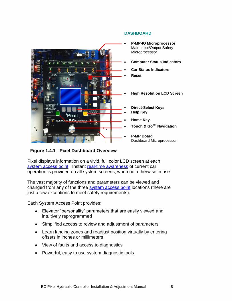
Pixel displays information on a vivid, full color LCD screen at each system access point. Instant real-time awareness of current car operation is provided on all system screens, when not otherwise in use. The vast majority of functions and parameters can be viewed and changed from any of the three system access point locations (there are just a few exceptions to meet safety requirements). Each System Access Point provides:
Elevator “personality” parameters that are easily viewed and intuitively reprogrammed
Simplified access to review and adjustment of parameters
Learn landing zones and readjust position virtually by entering offsets in inches or millimeters
View of faults and access to diagnostics
Powerful, easy to use system diagnostic tools
Figure 1.4.1 - Pixel Dashboard Overview
DASHBOARD
P-MP-IO Microprocessor Main Input/Output Safety Microprocessor
Computer Status Indicators
Car Status Indicators
Reset
High Resolution LCD Screen
Direct-Select Keys
Help Key
Home Key
Touch & GoTM
Navigation
P-MP Board
Dashboard Microprocessor
EC Pixel Hydraulic Controller Installation & Adjustment Manual 9
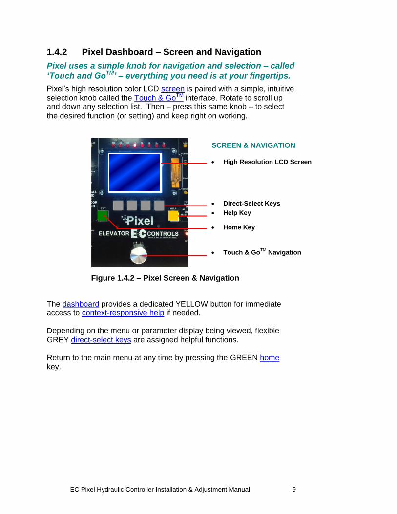
1.4.2 Pixel Dashboard – Screen and Navigation
Pixel uses a simple knob for navigation and selection – called ‘Touch and GoTM’ – everything you need is at your fingertips.
Pixel‟s high resolution color LCD screen is paired with a simple, intuitive selection knob called the Touch & GoTM interface. Rotate to scroll up and down any selection list. Then – press this same knob – to select the desired function (or setting) and keep right on working. The dashboard provides a dedicated YELLOW button for immediate access to context-responsive help if needed. Depending on the menu or parameter display being viewed, flexible GREY direct-select keys are assigned helpful functions. Return to the main menu at any time by pressing the GREEN home key.
Figure 1.4.2 – Pixel Screen & Navigation
SCREEN & NAVIGATION High Resolution LCD Screen
Direct-Select Keys
Help Key
Home Key
Touch & GoTM
Navigation
EC Pixel Hydraulic Controller Installation & Adjustment Manual 10
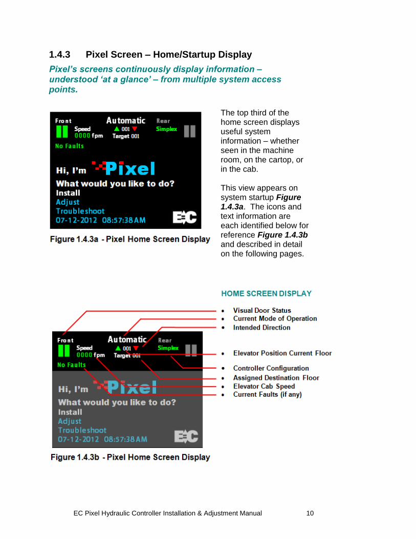
1.4.3 Pixel Screen – Home/Startup Display
Pixel’s screens continuously display information – understood ‘at a glance’ – from multiple system access points.
The top third of the home screen displays useful system information – whether seen in the machine room, on the cartop, or in the cab. This view appears on system startup Figure 1.4.3a. The icons and text information are each identified below for reference Figure 1.4.3b and described in detail on the following pages.
EC Pixel Hydraulic Controller Installation & Adjustment Manual 11
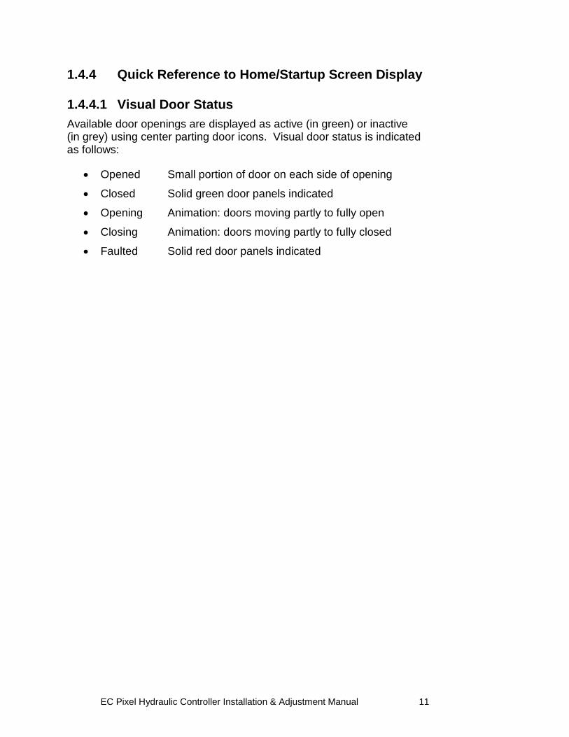
1.4.4 Quick Reference to Home/Startup Screen Display 1.4.4.1 Visual Door Status Available door openings are displayed as active (in green) or inactive (in grey) using center parting door icons. Visual door status is indicated as follows:
Opened Small portion of door on each side of opening
Closed Solid green door panels indicated
Opening Animation: doors moving partly to fully open
Closing Animation: doors moving partly to fully closed
Faulted Solid red door panels indicated
EC Pixel Hydraulic Controller Installation & Adjustment Manual 12
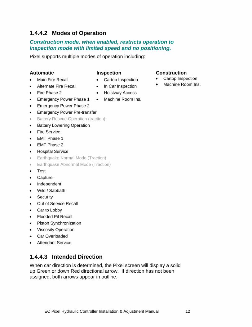
1.4.4.2 Modes of Operation
Construction mode, when enabled, restricts operation to inspection mode with limited speed and no positioning.
Pixel supports multiple modes of operation including:
Automatic
Main Fire Recall
Alternate Fire Recall
Fire Phase 2
Emergency Power Phase 1
Inspection
Cartop Inspection
In Car Inspection
Hoistway Access
Machine Room Ins.
Construction
Cartop Inspection
Machine Room Ins.
Emergency Power Phase 2
Emergency Power Pre-transfer
Battery Rescue Operation (traction)
Battery Lowering Operation
Fire Service
EMT Phase 1
EMT Phase 2
Hospital Service
Earthquake Normal Mode (Traction)
Earthquake Abnormal Mode (Traction)
Test
Capture
Independent
Wild / Sabbath
Security
Out of Service Recall
Car to Lobby
Flooded Pit Recall
Piston Synchronization
Viscosity Operation
Car Overloaded
Attendant Service
1.4.4.3 Intended Direction
When car direction is determined, the Pixel screen will display a solid up Green or down Red directional arrow. If direction has not been assigned, both arrows appear in outline.
EC Pixel Hydraulic Controller Installation & Adjustment Manual 13
1.4.4.4 Current and Destination Floors
The Pixel screen displays the current floor at all times, found between the up and down directional arrows, indicated in three digits. If a destination floor has been assigned, it will be displayed just below the current floor, labeled Target, indicated in three digits. The Target is dynamic, and may change during a run.
1.4.4.5 Speed
The Pixel screen displays cab speed, just to the right of the Front door icon. Scale can be toggled between fpm (feet per minute) and mps (meters per second).
1.4.4.6 Control System Configuration
The Pixel screen displays system configuration, just to the left of the Rear Door icon. Car configuration can be Simplex or Group. In group configuration, the current priority to assume dispatching functions for the group is indicated, under the word „Group‟.
1.4.4.7 Active Fault
The Pixel screen displays the active fault with the highest priority or No Faults if none present.
NOTE: Faults are classified as either latching or non-latching.
While non-latching faults self reset, all faults are recorded in fault counters and logs.
1.5 Pixel New Features Quick Overview
1.5.1 LandaTM Dual Positioning System
No more time consuming and costly hoistway work mounting vanes, wiring and readjusting switches.
Landa is a dual positioning system that provides absolute cab location information. Dual communication channels, one for each positioning system, provide truly independent redundancy for failsafe operation. Landa provides precision accuracy – tracking cab location to within 0.8 millimeter. All limits, slowdowns and landings are defined virtually, stored digitally, and easily readjusted. No wiring, vanes or switches are required in the hoistway (*except top physical limit switch as required by elevator safety code).
EC Pixel Hydraulic Controller Installation & Adjustment Manual 14
1.5.2 Virtual Safety Limits
Pixel knows where the car is at all times.
The Landa car positioning system captures high resolution position data that is maintained through power cycling. During the hoistway „learn‟ procedure, the control system generates and records the location and associated position for all required virtual safety limits. Once learned, virtual safety limits function in the same way that vane and switch systems worked in the past. Safety code requires placement of top physical limit switch, for which Pixel provides inputs (described in the wiring Section).
1.5.3 CAN-bus Network
Proven industrial standard communication protocol provides simplified interoperability using high speed dual CAN-bus networks.
The Pixel controller uses dual CAN-bus controller area networks to provide high speed internal system communication, including group to and between individual car controllers. Use of this industrial standard protocol opens the door to interoperability with a variety of current and future products and peripherals.
1.5.4 Parallel Independent Safety Processors
If at any time, Pixel’s two independent safety systems do not agree, an automatic system shutdown is executed to keep passengers safe.
In compliance with current elevator safety code, Pixel‟s design incorporates parallel independent safety processors. Two independent, redundant means are used to monitor safe operation. The logic output from both safety systems is continually compared. EC design engineers devised SP1, a powerful software-based safety processor, which is continually crosschecked by SP2, a hardware-based FPGA (Field Programmable Gate Array) safety processor.
EC Pixel Hydraulic Controller Installation & Adjustment Manual 15
1.5.5 Integrated I/O Testing and Remapping
Local diagnostics function whether or not the access point has an active connection to the system network.
Pixel has designed-in reliability and flexibility. Simple onboard I/O testing is supported at each system access point. Every I/O is provided with an associated LED indicator. If an I/O is found to have failed, remap I/O can be used to reassign this I/O to another location on the same PC board, or to another I/O board, using an intuitive, visually-based process.
1.5.6 Consolidated Field Wiring
Consolidated field wiring saves time while separating low and high voltage signals to help prevent component damaging wiring errors.
The Pixel controller cabinet has been designed so you can bring field wiring into a functional assigned color coded terminal strips – a convenience we call consolidated field wiring.
1.5.7 Remote AssistTM
Virtual tech support is delivered to your machine room on demand – with system access you always approve and control.
Elevator mechanics have long wished that support technicians could join them in the machine room with a simple call for help. Remote Assist enables the Pixel technical support team to virtually view the system you are working on, in real time, and provide guidance and recommendations.
1.6 Pixel Menu System Overview
Menu content is strategically organized, and logically sequenced, with related tasks grouped together.
The broad range of selections within the Pixel system are presented in menus, each containing a reasonable number of selections within each tier. The number of tiers has also been minimized to simplify navigation and selection. The breadth and depth of the Pixel menu system provides access to the extensive parameters demanded by the most experienced adjuster. But many installers will find that the top two or three menu tiers will satisfy the majority of their needs.
EC Pixel Hydraulic Controller Installation & Adjustment Manual 16
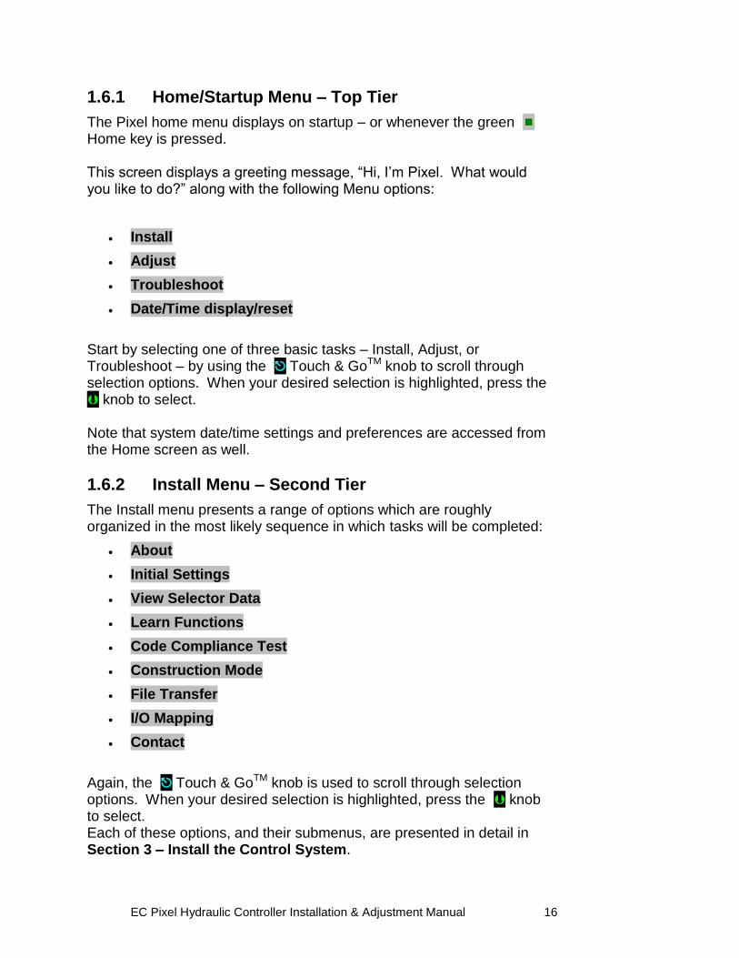
1.6.1 Home/Startup Menu – Top Tier
The Pixel home menu displays on startup – or whenever the green
Home key is pressed. This screen displays a greeting message, “Hi, I‟m Pixel. What would you like to do?” along with the following Menu options:
Install
Adjust
Troubleshoot
Date/Time display/reset
Start by selecting one of three basic tasks – Install, Adjust, or Troubleshoot – by using the Touch & GoTM knob to scroll through selection options. When your desired selection is highlighted, press the knob to select. Note that system date/time settings and preferences are accessed from the Home screen as well.
1.6.2 Install Menu – Second Tier
The Install menu presents a range of options which are roughly organized in the most likely sequence in which tasks will be completed:
About
Initial Settings
View Selector Data
Learn Functions
Code Compliance Test
Construction Mode
File Transfer
I/O Mapping
Contact
Again, the Touch & GoTM knob is used to scroll through selection options. When your desired selection is highlighted, press the knob to select. Each of these options, and their submenus, are presented in detail in Section 3 – Install the Control System.
EC Pixel Hydraulic Controller Installation & Adjustment Manual 17
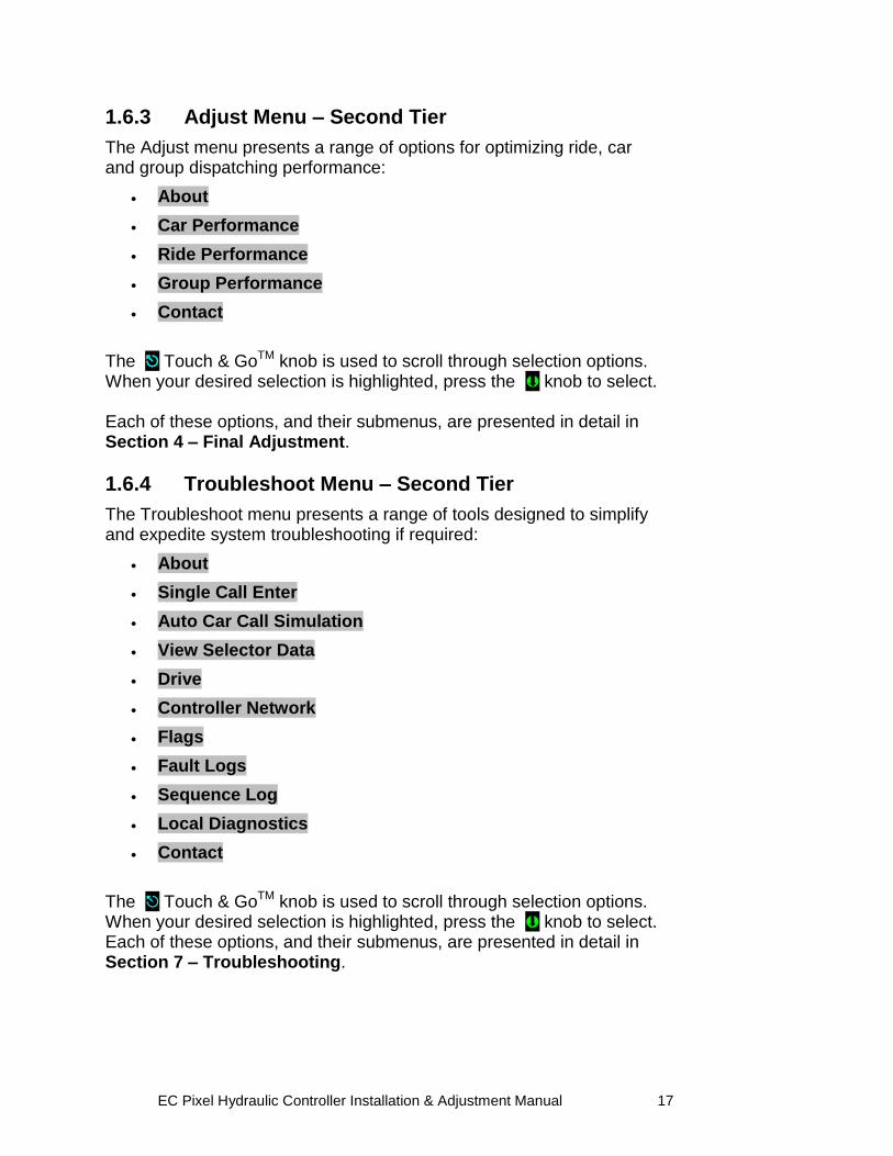
1.6.3 Adjust Menu – Second Tier
The Adjust menu presents a range of options for optimizing ride, car and group dispatching performance:
About
Car Performance
Ride Performance
Group Performance
Contact
The Touch & GoTM knob is used to scroll through selection options. When your desired selection is highlighted, press the knob to select. Each of these options, and their submenus, are presented in detail in Section 4 – Final Adjustment.
1.6.4 Troubleshoot Menu – Second Tier
The Troubleshoot menu presents a range of tools designed to simplify and expedite system troubleshooting if required:
About
Single Call Enter
Auto Car Call Simulation
View Selector Data
Drive
Controller Network
Flags
Fault Logs
Sequence Log
Local Diagnostics
Contact
The Touch & GoTM knob is used to scroll through selection options. When your desired selection is highlighted, press the knob to select. Each of these options, and their submenus, are presented in detail in Section 7 – Troubleshooting.
EC Pixel Hydraulic Controller Installation & Adjustment Manual 18
Section 2 – Your Installation Plan 2.1 General Information
This section contains important instructions and recommendations to ensure successful Pixel Control System installation.
Successful installation and reliable, trouble free operation of all elevator control equipment depends on proper assessment of the installation environment and proper wiring methods. Completing both correctly protects equipment from disruption by external sources.
2.2 Installation Considerations
When selecting the best physical location for the control equipment consider the following:
a. Make sure the control system is placed logically, while taking into consideration all elevator system components and non-elevator equipment sharing the space.
b. Provide adequate working space for control system installation, wiring, and maintenance. Elevator Controls standard equipment enclosures require front access only. This eliminates many constraints that would otherwise limit how equipment can be located.
c. Do not install equipment where it may create a hazard.
WARNING: Install Pixel Control equipment according to all
applicable electrical, fire, and building codes. Improper installation and/or equipment location may create a HAZARDOUS CONDITION.
d. Do not install control system components in areas or on surfaces where
there is exposure to vibration that may be produced by other equipment. Modern control systems contain socket-mounted parts whose function may be compromised by vibration.
e. Provide adequate lighting for safety and efficiency.
f. An internet connection, with fixed IP address, is desirable for access to Remote AssistTM from the EC factory technical support team.
g. If wireless service at the installation location is poor or intermittent, have a wired phone installed in the machine room.
EC Pixel Hydraulic Controller Installation & Adjustment Manual 19
2.3 Environmental Considerations
The elevator control system should be installed according to the following requirements to ensure proper operation and longevity:
a. Temperature inside the control system enclosure should be maintained between 32 and 104 degrees Fahrenheit (0 to 40 degrees Celsius). Temperatures outside this range may effect normal operation and/or reduce system life. If required, make provisions for machine room air conditioning. EC can quote and provide an enclosure-mounted air conditioning unit.
b. Air in the machine room should be free of corrosive gases and sufficiently dry to prevent condensation from moisture. NEMA 4 or NEMA 12 enclosures, with integral air conditioning units, are recommended for applications that do not meet these requirements. EC can quote and provide the full range of specialized NEMA rated enclosures for proper and safe operation in non-standard environments.
c. Locate control system enclosures and components away from any window or opening to minimize the risk of equipment damage due to severe weather conditions.
d. Protect control system equipment from exposure to extreme levels of electromagnetic (EM) and radio frequency (RF) radiation. EC control systems are certified to current EMI/RFI standards though independent testing by CKC Laboratories, Inc. However, note that EMI and RFI have the potential to interfere with normal operation of any electronic system.
NOTE: Hand-held communications devices used close to the system
microprocessors have been known to generate disruptive RF interference.
2.4 Recommended Tools, Test Equipment & Manuals
The following tools are recommended for installation:
a. Digital multi-meter
b. Assorted tools used for electronics work such as pliers, cutters, flash light, EC small straight blade screwdriver (supplied with each controller), etc
c. Amprobe or similar probe equipped ammeter
d. Telephone
e. Test weights
f. Control system “as built” job wiring prints
g. This installation and adjustment manual
h. Solid State Starter Motor Control Manual, if applicable
EC Pixel Hydraulic Controller Installation & Adjustment Manual 20
i. Oscilloscope and meter that measures meg-ohms may be desirable for advanced troubleshooting (rarely required)
2.5 Controller Wiring Guidelines
CAUTION: Restrict access to elevator control equipment and apparatus to
qualified personnel only.
NOTE: It is very important to follow control system wiring guidelines to
prevent problems with EMI/RFI interference and feeder line pollution.
NOTE: Wiring to controller terminals must be done neatly and carefully. Stranded wire conductors must be twisted together, avoiding stray strands that could create short circuits if not contained in terminals.
NOTE: All terminals and cable connectors should be checked to ensure that they are properly and solidly seated. When connecting flat cable connectors, be certain to match pin #1 marks (arrow symbol on connectors; red stripe on cable) to prevent mechanical damage to connectors and electrical damage to system components.
There are four wiring entry points provided in order to maintain proper separation between wiring for various purposes to ensure proper system operation:
a. Power Wiring: The line power feeders and ground coming from the elevator service disconnect.
b. Motor Wiring: Power wiring to pump motor.
c. Safety and Logic Wiring: All wiring to fixtures and switches, as well as signal cross-connect cables from one car to another in a multi-car group system.
d. Communications Cable: Communication cables run from one controller to another in a group of two or more cars.
NOTE: The standard EC NEMA 1 enclosure is provided with factory
knockouts for recommended ideal field wiring entry points. Knockouts and intended use are listed:
a. Top right side
Communication cable
EC Pixel Hydraulic Controller Installation & Adjustment Manual 21
b. Middle right side
Safety & Logic wiring
c. Lower left and right side
Main Line Power wiring
Pump Motor wiring
WARNING: METAL SHAVINGS AND/OR WIRE CLIPPINGS can cause
immediate and delayed DAMAGE to circuits – in any part of the system – if they bridge or short any circuit or connection. They can also COMPROMISE SAFE AND PROPER SYSTEM OPERATION if they become positioned in a way that modifies a circuit or circuits.
CAUTION: Ensure that metallic shavings and/or wire clippings are minimized and prevented from remaining in any enclosure interior. Thoroughly check for and remove residue before applying power. Methods used to capture and remove metal fragments should not be allowed to create static buildup or discharge.
Good Practice: Soft clean paint brush (gently sweep particles on enclosure bottom into pile and remove); masking tape (use to remove particles; create adhesive pocket under intended hole locations with tape to catch shavings when drilling). Risky Practice: Use of small vacuum (potential ESD electrostatic discharge damage); compressed air (may drive particles into inaccessible or undetectable locations, potential for eye injury).
NOTE: Alternate wiring entry points may be created in the field to
accommodate specific installation conditions.
NOTE: Study your control system layout to develop the best arrangement
for keeping the five entry points separated and laid out logically to suit your particular application.
EC Pixel Hydraulic Controller Installation & Adjustment Manual 22
Section 3 – Install the Control System 3.1 Pixel Hydraulic Control System Steps to Startup
Protect printed circuit boards from dust and foreign materials. Remove main fuses. Complete elevator controller mounting, installation, and wiring.
Observe controller field terminal locations in relation to wiring ducts to determine optimum locations for wiring to enter the control equipment enclosure. Complete the steps in Sections 3.2 through 3.4.5 below in order to run the car on Construction mode.
CAUTION: Use care to protect circuit boards from metal debris
when cutting.
NOTE: The standard Pixel Hydraulic controller enclosure has several ¾”
knockouts marked for wiring ducts which can be used as guides for location of knockouts required for each particular job.
3.2 Install the Controller Cabinet
In Section 2 you reviewed the general considerations for machine room layout and develop your installation plan. Now, proceed to locate and mount the controller enclosure.
3.3 Wire the Control System
3.3.1 Test Ground Continuity
Test all terminals for continuity to ground. If continuity is found, resolve the problem before proceeding.
NOTE: Terminal 3 is connected to ground and used as system common.
3.3.2 Remove Primary Controller Fuses
Remove fuses FL1, FL2, FCT1, FCT2, F4A in order to remove power to controller logic, and the door operator. Place Machine Room Inspection to INSP and the Test switch to TEST. Both switches are located on the P-MP board.
NOTE: Always review job prints to confirm correct fuse designations and
amperages, as well as to become familiar with job specific circuit requirements.
EC Pixel Hydraulic Controller Installation & Adjustment Manual 23
3.3.3 Place Disconnect Switch in Off Position
Place the disconnect switch in the off position and check voltage on the line side to verify that all three legs are correct based on job prints page 1.
WARNING: CONFIRM THAT FEEDER LINE VOLTAGE is within 10% of
specified control voltage or PERMANENT DAMAGE could occur to both the motor and elevator control system logic. TURN OFF THE MAIN DISCONNECT and CORRECT any voltage problem BEFORE PROCEEDING with installation.
CAUTION: Remove any protective covering that may still be in place on PC boards and components before applying power.
3.3.4 Wire Main Line to Controller
Wire the main line from the disconnect switch to the motor starter or terminal block provided in the controller enclosure as indicated on job prints page 1.
NOTE: Use proper wire size for amperage.
NOTE: Ground wire size must provide equal or greater ampacity than the
incoming feeders. 3.3.5 Verify Supply Voltages at Equipment
Turn on the disconnect switch to verify that voltages at controller terminals are correct based on job prints page 1. Turn off the disconnect switch then replace the fuses removed previously in Section 3.3.2 above. Turn on the disconnect switch and confirm that computer power supply input and output voltages are correct based on job prints page 2. Verify that buss voltages are 24 volts DC for terminals 6, 50, 50F, and S24V; and 120 VAC for terminal 4A. Confirm that the P-MP color display is on and the screen shows the Pixel home/startup display, “Hi, I‟m Pixel. What would you like to do?”
NOTE: After verifying input voltages and fuses as required per job prints, if
you are unable to correct conditions to confirm voltages and behaviors described, call Elevator Controls technical support at 916-428-1708.
EC Pixel Hydraulic Controller Installation & Adjustment Manual 24
3.3.6 Pixel Dashboard Interface – Indicators
You will find multiple LED indicators have been provided on PC boards, and onboard computer diagnostics are included. Both are very useful tools that will save installation and troubleshooting time.
NOTE: Review the Pixel system dashboard indicators and
switchgear before continuing to the Section 3.3.7.
EC Pixel Hydraulic Controller Installation & Adjustment Manual 25
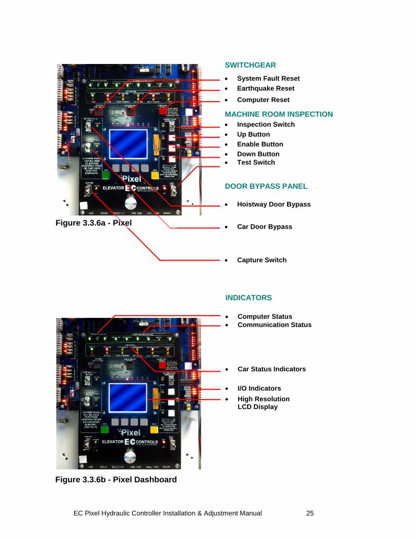
Figure 3.3.6b - Pixel Dashboard Indicators
INDICATORS
Computer Status
Communication Status
Car Status Indicators
I/O Indicators
High Resolution LCD Display
SWITCHGEAR
System Fault Reset
Earthquake Reset
Computer Reset
MACHINE ROOM INSPECTION
Inspection Switch
Up Button
Enable Button
Down Button
Test Switch
DOOR BYPASS PANEL
Hoistway Door Bypass
Car Door Bypass
Capture Switch
Figure 3.3.6a - Pixel Switchgear
EC Pixel Hydraulic Controller Installation & Adjustment Manual 26
Pixel Navigation Icons
Knob Rotate/Push Key Press
Rotate to locate Home
Push to select Direct-Select
Help
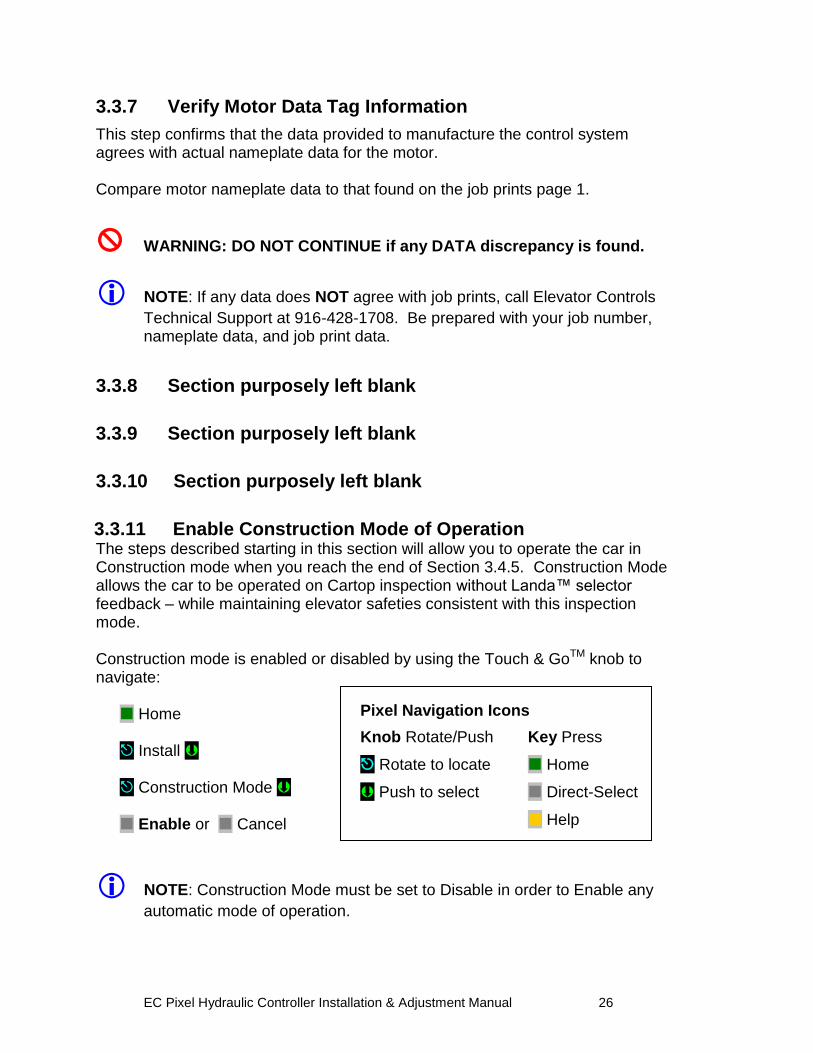
3.3.7 Verify Motor Data Tag Information This step confirms that the data provided to manufacture the control system agrees with actual nameplate data for the motor. Compare motor nameplate data to that found on the job prints page 1.
WARNING: DO NOT CONTINUE if any DATA discrepancy is found.
NOTE: If any data does NOT agree with job prints, call Elevator Controls
Technical Support at 916-428-1708. Be prepared with your job number, nameplate data, and job print data.
3.3.8 Section purposely left blank
3.3.9 Section purposely left blank
3.3.10 Section purposely left blank
3.3.11 Enable Construction Mode of Operation The steps described starting in this section will allow you to operate the car in Construction mode when you reach the end of Section 3.4.5. Construction Mode allows the car to be operated on Cartop inspection without Landa™ selector feedback – while maintaining elevator safeties consistent with this inspection mode. Construction mode is enabled or disabled by using the Touch & GoTM knob to navigate: Home Install Construction Mode Enable or Cancel
NOTE: Construction Mode must be set to Disable in order to Enable any
automatic mode of operation.
EC Pixel Hydraulic Controller Installation & Adjustment Manual 27
3.3.12 Wire Circuits Required for Construction Mode
Construction Mode allows the car to be operated on Car Top or Machine Room Inspection modes. All safety circuits required for these modes of operation must be operational:
a. Set HOISTWAY DOOR BYPASS and CAR DOOR BYPASS SWITCHES to BYPASS position; OR ensure that all car and hoistway gates and locks are closed.
b. Wire Motor to Motor Contactor; refer to page 1 of prints for guidance.
c. Governor switch contact wired between Terminals 4A and GOV or Jumper terminal 4A to GOV if no governor device is required.
d. Wire Car-Top Station Pendant unit, refer to page QR1 of the prints:
1. Switch between 4A and ICT
2. Enable Push Button between 4A and ICTE
3. Up Push Button between 4A and ICTU
4. Down Push Button between 4A and ICTD
5. Stop Push Button between 4A and SAFH and SAFC
NOTE: Use proper wire size for amperage and use ground wire size equal
or greater ampacity than the motor power wires.
3.3.13 Section purposely left blank
3.3.14 Verify Motor rotation
NOTE: Section 3.3.14 is for Wye-Delta or Delta Motor Starter. Skip to
Section 3.3.15 if using Solid State Starter.
3.3.14.1 Pump Motor Rotation (Wye Delta or Delta Starter only) Verify proper rotation of the pump motor by momentarily closing starter contacts (use the Y Contactor for Y-Delta starters) and BK redundant motor contactor if required by job, refer to page 1 of prints. Do not hold for more than one second). If rotation is incorrect, interchange two of the leads at disconnect, or the top of the starter (power lines only, not motor leads).
3.3.14.2 Reverse Phase Relay (Wye Delta or Delta Starter only) Observe the RP (Reverse Phase) relay. If it is picked, proceed to the next step. If RP is not picked, check fuses FL1, FL2, and FL3 and make sure that, if an adjustable sensor is provided, the setting is correct.
EC Pixel Hydraulic Controller Installation & Adjustment Manual 28
If this does not cause the RP relay to pick, turn off the power and reverse two of the three wires (probably #14 or #18 gauge) that feed 3-phase AC power from the starter to the rest of the controller (these wires will typically be at the top of the starter). Restore power. The RP relay should pick. If not, replace the RP plug-in sensor or the RP relay and repeat this step.
NOTE: Section 3.3.15 is for Solid State Motor Starter. (Skip to Section
3.3.14 above if using Wye-Delta or Delta Starter).
3.3.15 Review Instructions (Solid State Starter only) Read the manufacturer‟s solid-state starter unit (SSSU) application instructions and use for reference through this section. The ready light should come on when power is applied to the input side of the SSSU. If there is a phase loss the phase reverse indicator will come on. Verify that the line-to-line voltage is the proper value. If incorrect, swap any two power input lines to the starter. This should correct the problem and the ready LED indicator should come on. Refer to SSSU manufacturer‟s manual for advanced troubleshooting.
3.3.15.1 Proper Pump Motor Rotation (Solid State Starter only)
Verify proper rotation of the pump motor by momentarily jumpering the enable contacts (Motor Run Input) on the SSSU, refer to page 4 of prints to jump terminals connected while AA auxiliary contact 1 is closed. If motor rotation is reversed, correct by swapping two of the motor winding connections (refer to the SSSU manufacturer manual for directions to properly swap two of the motor winding connections).
3.4 Run the Car on Construction Mode
NOTE: Pixel will prevent the car from moving until the required
Construction Mode signal status is achieved.
NOTE: Construction Mode allows the car to run On Car Top or In Car
Inspection in low speed only regardless of High Speed on INS parameter setting.
Navigate to the home screen, then follow step-by-step instructions.
Home
Confirm that the Pixel screen displays, “No Faults.” If a fault condition is indicated
Help
EC Pixel Hydraulic Controller Installation & Adjustment Manual 29
Read the fault description and follow instructions for resolving the issue Once recommended actions are completed press the
System Fault Reset
This will clear a “fault latched” state.
NOTE: The highest priority fault is displayed on the Pixel home screen (No
Faults is the default). Lower priority faults may be revealed once the first fault is resolved. Repeat instructions above until No Fault are displayed.
NOTE: Faults are classified as either latching or non-latching. While non-
latching faults self reset, all faults are recorded in fault counters and logs.
3.4.1 Attempt to Move Car
Using the Car-Top Station Pendant unit confirm the car can be commanded to move in the up or down direction, verify respective up or down valve unit is energized matching commanded direction of travel, refer to page 1 of prints for valve coils wiring interface.
3.4.2 Wye Delta Timeout Adjustment
NOTE: Section 3.4.2 applies to Wye-Delta mechanical starter units only,
skip to 3.4.3 if Solid State Starter unit is being used. For WYE-DELTA starters, the proper transition time from Wye to Delta should be verified and adjusted for smooth pump motor acceleration and up to speed transition, the Wye Delta Timeout is found navigating to: Home Adjust Car Performance Timers Hydraulic Timers Wye Delta Timeout
EC Pixel Hydraulic Controller Installation & Adjustment Manual 30
3.4.3 Up To Speed Solid State Starter Adjustment
NOTE: Section 3.4.3 applies to Solid State Starters units only for Wye-
Delta mechanical starter skip to 3.4.2 above. For Solid State Starter Unit or Variable Voltage Variable Frequency starter is provided, refer to the manufacturer‟s manual for acceleration and up-to- speed motor control adjustment.
3.4.4 Valves Adjustment
Refer to the valves manufacturer‟s manual to adjust car Inspection speed, low speed up and downs valves, to allow for car use to finalize elevator installation.
NOTE: Low speed valves may need to be adjusted during final adjustment
to achieve performance and comfortable landing approach.
3.4.5 System Startup Complete
At this point the system startup is complete: the elevator car should run correctly on Construction mode in Car Top Inspection or Controller Inspection modes. If you are unable to run the car, review the steps in Section 3 to section 3.4.4 above, and repeat as required. Elevator system hardware installation should be completed next, including installation of the Cartop box, Car Operating Panel, Landa™ dual head positioning system etc. in order to enable the car to transition from Construction Mode to Inspection and Automatic modes of operation.
3.5 System Components Installation and Wiring
3.5. 1 TOC Box Installation
The Pixel TOC box is supplied with necessary hardware to permanently attach it to the crosshead using unistrut and clamps. Survey the cartop and determine the best quadrant for mounting, setup and ease of wiring to: door operator(s), load weighing devices, Landa™ positioning hardware, fans and cab accessories to the TOC box. Refer to job prints page TOC1 for instructions and details of TOC mechanical installation. Install the TOC box provided. If your TOC box includes the optional pre-wired Car Top Inspection Station, install the TOC box the light bulb and light bulb mesh protection provided. Install the Emergency Stop push button switch.
EC Pixel Hydraulic Controller Installation & Adjustment Manual 31
NOTE: Pixel‟s pre-wired Car Top Inspection Station light bulb, light bulb
mesh protection, and the Emergency Stop push button switch are shipped inside the TOC box.
Once the TOC box has been installed, if you did not order the pre-wired Car Top Inspection Station, wire the job Inspection Station provided by others to the TOC Box, referring to page CW of the prints for wiring instructions.
3.5.2 COP Installation Wiring
Refer to your COP panel provider and cab manufacturer for any special installation instructions for the pre-wired COP panel. Use the harness provided to connect to the TOC box. Refer to job prints page CW for harness wiring details.
NOTE: A color-coded harness is provided to simplify connection of the
COP(s) to the TOC. One harness is shipped with the TOC box for each COP.
NOTE: Place the switch for Independent Service to on and leave it on to
make sure car will open doors while transferring from TEST to Independent service as indicated in Section 4, final adjustment below, and to enable access to inside of the cab.
3.5.3 Traveler Cable Installation and Wiring
Install the Traveler Cable and wiring. Refer to your traveler cable provider and cab manufacturer for any special installation instructions. Refer to page CW of the prints for traveler wire count as well as for one-to-one terminal wiring instructions.
NOTE: A separate terminal strip is provided, in the controller, to wire one to
one the traveler cable conductors to the controller. Another identical terminal strip is located inside the TOC box. The top portion of the TOC box terminal strip is intended for termination of traveler cable conductors.
3.5.4 Landa™ Positioning System Installation
3.5.4.1 Encoded Tape
Landa™ Positioning System is supplied with necessary hardware to permanently attach it to the rails and crosshead using unistrut and clamps. Survey the cartop and hoistway to determine the quadrant that provides clearance for the Encoded Tape to run the entire length of the hoistway. Refer to page PS1 of the prints for installation guidelines.
Start by fastening the top end of the tape to the top-of-hoistway bracket, then allow the roll to descend down the hoistway.
EC Pixel Hydraulic Controller Installation & Adjustment Manual 32
NOTE: The Encoded Tape is polarized so it must be installed with the start
position at the bottom of the hoistway. To simplify installation, tape has been coiled with the top end on the outside of the roll.
3.5.4.2 Landa™ Dual Sensor Head Installation and Wiring
The sensor heads can be mounted on any of their three sides to facilitate encoded tape position and sensor head assemble locations. Refer to page PS1 of the prints for installation guidelines. Connect the Sensor heads to the TOC box using the color-coded wiring harnesses provided. Refer to page 6 of the prints for wiring details.
NOTE: The Auxiliary sensor head (selector 2) is the one mounted at the
top of the Landa Dual Sensor Head bracket assembly. It connects to the TOC JASEL connector on the TOC board. The Main sensor head (selector 1) is the one mounted at the bottom of the bracket, and connects to the TOC JMSEL connector.
NOTE: The sensor head connector location must be at the top of sensor
head unit to ensure proper sensor head orientation.
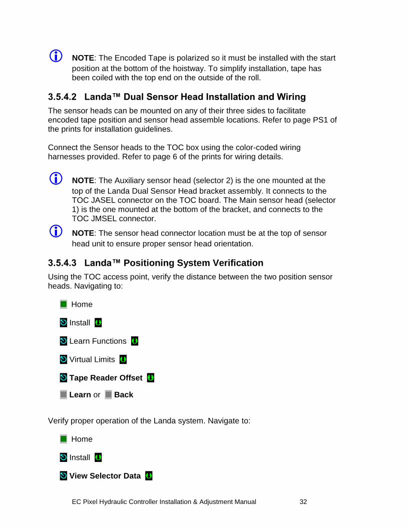
3.5.4.3 Landa™ Positioning System Verification
Using the TOC access point, verify the distance between the two position sensor heads. Navigating to:
Home Install Learn Functions
Virtual Limits
Tape Reader Offset
Learn or Back
Verify proper operation of the Landa system. Navigate to: Home Install View Selector Data
EC Pixel Hydraulic Controller Installation & Adjustment Manual 33
a. Confirm that the position displayed for selector 1 should be smaller than selector 2. If not, swap the pluggable terminal strips JMSEL and JASEL on the P-TOC board.
b. Confirm that selector positions increment and decrement together as you run the car either up or down.
c. Confirm that the RAW delta difference is between 0.7 to1 foot, and roughly matches the physical distance between the two sensor heads as mounted.
NOTE: If you cannot confirm performance as described above, repeat
steps in Section 3.5.4 until the landing system operates correctly.
3.5.5 Cab and Hoistway Wiring
3.5.5.1 Mechanical Switches and Peripherals Wiring
Refer to page CW of the prints for cab peripherals, such as Door Operator, Photo Detectors, Fans and Lights, etc. requirements and wiring guidelines. Install and wire as necessary. Refer to page HMW of the prints for hoistway switches requirements and wiring guidelines. Install and wire necessary mechanical switches.
3.5.5.2 Hall Network
Refer to your Fixture manufacturer for any special installation instructions for the EC-Ready pre-wired Hall Stations. See page QR4/ HMW of the prints for hall station node wiring guidelines.
NOTE: CAN-driven hall station nodes require power and data wiring. Care
must be observed not to interchange data wires and power wires so node(s) will be able to access the network and communicate.
3.5.5.2.1 Pixel RJ45 Hall Wiring Option
If the controller purchase included the optional Pixel RJ45 Hall Wiring option, consisting of all the necessary RJ45 cables and RJ45 cable splitters to wire the Hall network to Pixel, refer to page QR4/ HMW of prints and observe that the use of RJ45 splitters is optional the P-Hall boards have two RJ45 female jacks that can be used to interconnect the hall network eliminating the need of splitters and the three feet RJ45 cables used to connect from the splitter to the hall nodes.
NOTE: The on board P-Hall RJ45 female jacks can be used for either input
or output to connect them directly to the hall network eliminating the RJ45 splitters and the three feet cables from splitter to hall nodes.
EC Pixel Hydraulic Controller Installation & Adjustment Manual 34
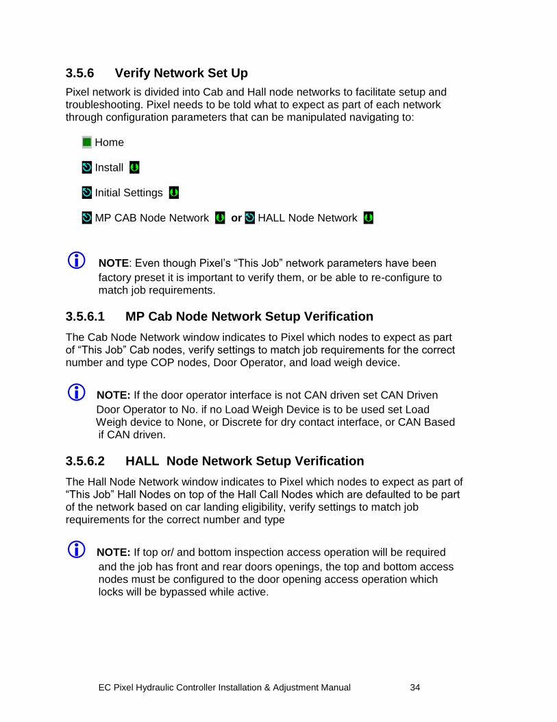
3.5.6 Verify Network Set Up
Pixel network is divided into Cab and Hall node networks to facilitate setup and troubleshooting. Pixel needs to be told what to expect as part of each network through configuration parameters that can be manipulated navigating to: Home Install Initial Settings MP CAB Node Network or HALL Node Network
NOTE: Even though Pixel‟s “This Job” network parameters have been
factory preset it is important to verify them, or be able to re-configure to match job requirements.
3.5.6.1 MP Cab Node Network Setup Verification
The Cab Node Network window indicates to Pixel which nodes to expect as part of “This Job” Cab nodes, verify settings to match job requirements for the correct number and type COP nodes, Door Operator, and load weigh device.
NOTE: If the door operator interface is not CAN driven set CAN Driven
Door Operator to No. if no Load Weigh Device is to be used set Load Weigh device to None, or Discrete for dry contact interface, or CAN Based
if CAN driven.
3.5.6.2 HALL Node Network Setup Verification
The Hall Node Network window indicates to Pixel which nodes to expect as part of “This Job” Hall Nodes on top of the Hall Call Nodes which are defaulted to be part of the network based on car landing eligibility, verify settings to match job requirements for the correct number and type
NOTE: If top or/ and bottom inspection access operation will be required
and the job has front and rear doors openings, the top and bottom access nodes must be configured to the door opening access operation which locks will be bypassed while active.
EC Pixel Hydraulic Controller Installation & Adjustment Manual 35
3.5.7 Verify Network Communications
Once wiring has been completed, and the network set up verified, Pixel needs to acknowledge each node throughout the network, to facility this task Pixel network verification has been divided into four landscape windows as follows:
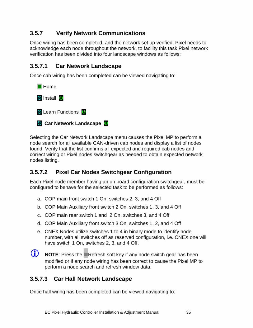
3.5.7.1 Car Network Landscape
Once cab wiring has been completed can be viewed navigating to:
Home Install
Learn Functions Car Network Landscape
Selecting the Car Network Landscape menu causes the Pixel MP to perform a node search for all available CAN-driven cab nodes and display a list of nodes found. Verify that the list confirms all expected and required cab nodes and correct wiring or Pixel nodes switchgear as needed to obtain expected network nodes listing.
3.5.7.2 Pixel Car Nodes Switchgear Configuration
Each Pixel node member having an on board configuration switchgear, must be configured to behave for the selected task to be performed as follows:
a. COP main front switch 1 On, switches 2, 3, and 4 Off
b. COP Main Auxiliary front switch 2 On, switches 1, 3, and 4 Off
c. COP main rear switch 1 and 2 On, switches 3, and 4 Off
d. COP Main Auxiliary front switch 3 On, switches 1, 2, and 4 Off
e. CNEX Nodes utilize switches 1 to 4 in binary mode to identify node number, with all switches off as reserved configuration, i.e. CNEX one will have switch 1 On, switches 2, 3, and 4 Off.
NOTE: Press the Refresh soft key if any node switch gear has been
modified or if any node wiring has been correct to cause the Pixel MP to perform a node search and refresh window data.
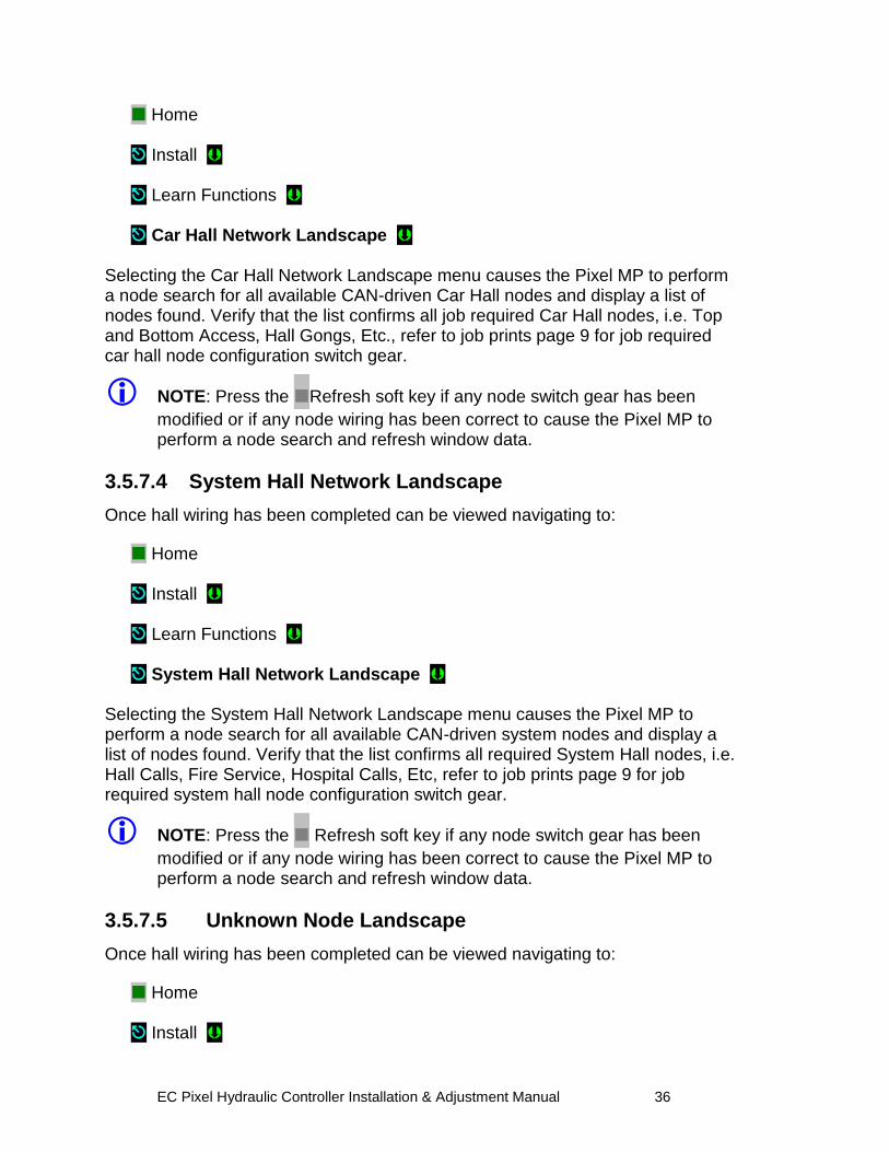
3.5.7.3 Car Hall Network Landscape
Once hall wiring has been completed can be viewed navigating to:
EC Pixel Hydraulic Controller Installation & Adjustment Manual 36
Home Install Learn Functions Car Hall Network Landscape
Selecting the Car Hall Network Landscape menu causes the Pixel MP to perform a node search for all available CAN-driven Car Hall nodes and display a list of nodes found. Verify that the list confirms all job required Car Hall nodes, i.e. Top and Bottom Access, Hall Gongs, Etc., refer to job prints page 9 for job required car hall node configuration switch gear.
NOTE: Press the Refresh soft key if any node switch gear has been
modified or if any node wiring has been correct to cause the Pixel MP to perform a node search and refresh window data.
3.5.7.4 System Hall Network Landscape
Once hall wiring has been completed can be viewed navigating to:
Home Install Learn Functions System Hall Network Landscape
Selecting the System Hall Network Landscape menu causes the Pixel MP to perform a node search for all available CAN-driven system nodes and display a list of nodes found. Verify that the list confirms all required System Hall nodes, i.e. Hall Calls, Fire Service, Hospital Calls, Etc, refer to job prints page 9 for job required system hall node configuration switch gear.
NOTE: Press the Refresh soft key if any node switch gear has been
modified or if any node wiring has been correct to cause the Pixel MP to perform a node search and refresh window data.
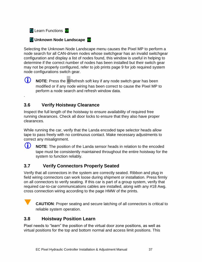
3.5.7.5 Unknown Node Landscape
Once hall wiring has been completed can be viewed navigating to:
Home Install
EC Pixel Hydraulic Controller Installation & Adjustment Manual 37
Learn Functions Unknown Node Landscape
Selecting the Unknown Node Landscape menu causes the Pixel MP to perform a node search for all CAN-driven nodes whose switchgear has an invalid switchgear configuration and display a list of nodes found, this window is useful in helping to determine if the correct number of nodes has been installed but their switch gear may not be properly configured, refer to job prints page 9 for job required system node configurations switch gear.
NOTE: Press the Refresh soft key if any node switch gear has been
modified or if any node wiring has been correct to cause the Pixel MP to perform a node search and refresh window data.
.
3.6 Verify Hoistway Clearance
Inspect the full length of the hoistway to ensure availability of required free running clearances. Check all door locks to ensure that they also have proper clearances. While running the car, verify that the Landa encoded tape selector heads allow tape to pass freely with no continuous contact. Make necessary adjustments to correct any misalignment.
NOTE: The position of the Landa sensor heads in relation to the encoded
tape must be consistently maintained throughout the entire hoistway for the system to function reliably.
3.7 Verify Connectors Properly Seated
Verify that all connectors in the system are correctly seated. Ribbon and plug in field wiring connectors can work loose during shipment or installation. Press firmly on all connectors to verify seating. If this car is part of a group system, verify that required car-to-car communications cables are installed, along with any #18 Awg. cross connection wiring according to the page HMW of the prints.
CAUTION: Proper seating and secure latching of all connectors is critical to
reliable system operation.
3.8 Hoistway Position Learn
Pixel needs to “learn” the position of the virtual door zone positions, as well as virtual positions for the top and bottom normal and access limit positions. This
EC Pixel Hydraulic Controller Installation & Adjustment Manual 38
process can be completed all at once or by individual ”target”. The learn process is broken into sections for clarity.
NOTE: Pixel must learn the virtual bottom landing door zone position first
such position will be used to normalize all other virtual positions.
3.8.1 Floor Setup
3.8.1.1 Bottom Landing Setup
Pixel must “learn” the position of the bottom landing first, such position must be learned by positioning the car at the bottom landing position. The bottom landing position will be used to normalize the encoded position read from the tape at the bottom landing to 1.2 feet and use this virtual position to scale all other floors and virtual limits required by Pixel logic.
NOTE: The bottom landing position does not have to be set precisely at
this time, its value will be fine tuned during Final Adjustment Section 4, and all other positions will be automatically adjusted to reflect change in bottom floor normalized position.
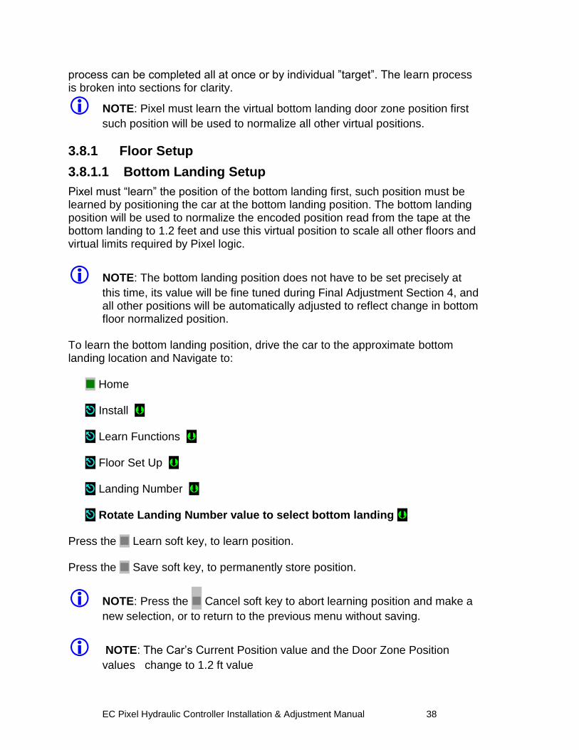
To learn the bottom landing position, drive the car to the approximate bottom landing location and Navigate to:
Home Install Learn Functions Floor Set Up Landing Number Rotate Landing Number value to select bottom landing
Press the Learn soft key, to learn position. Press the Save soft key, to permanently store position.
NOTE: Press the Cancel soft key to abort learning position and make a
new selection, or to return to the previous menu without saving.
NOTE: The Car‟s Current Position value and the Door Zone Position
values change to 1.2 ft value
EC Pixel Hydraulic Controller Installation & Adjustment Manual 39
NOTE: The Down Normal Terminal virtual switch position, DNL, will be
defaulted to a position 0.2 Feet below the bottom landing Door Zone Position value, i.e. 1 Foot, its position can be adjusted from 0.1 to 0.5 Feet as needed to match elevator performance.
3.8.1.2 All Other Landings Setup
Pixel now can use the bottom landing learned position to learn and normalize the remaining landing positions. Such landing positions can be learned by Learn by
Position (indicated by this symbol) or Learn by Input Value (indicated by this
symbol)
NOTE: The landing position does not have to be set precisely at this
time – values will be fine tuned during Final Adjustment Section 4.
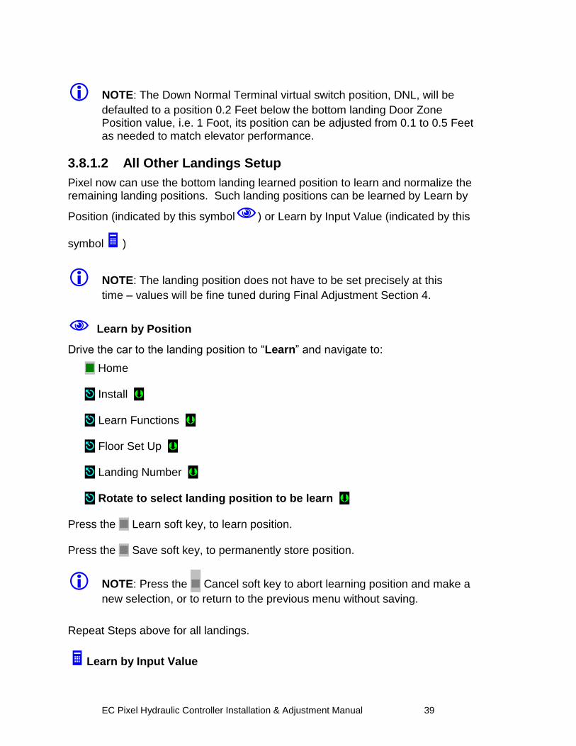
Learn by Position
Drive the car to the landing position to “Learn” and navigate to:
Home Install Learn Functions Floor Set Up Landing Number Rotate to select landing position to be learn
Press the Learn soft key, to learn position. Press the Save soft key, to permanently store position.
NOTE: Press the Cancel soft key to abort learning position and make a
new selection, or to return to the previous menu without saving.
Repeat Steps above for all landings.
Learn by Input Value
EC Pixel Hydraulic Controller Installation & Adjustment Manual 40
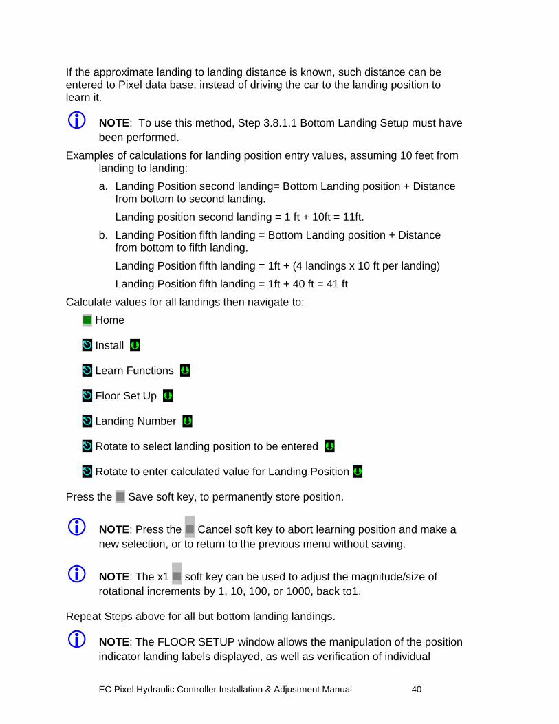
If the approximate landing to landing distance is known, such distance can be entered to Pixel data base, instead of driving the car to the landing position to learn it.
NOTE: To use this method, Step 3.8.1.1 Bottom Landing Setup must have
been performed.
Examples of calculations for landing position entry values, assuming 10 feet from landing to landing:
a. Landing Position second landing= Bottom Landing position + Distance from bottom to second landing.
Landing position second landing = 1 ft + 10ft = 11ft.
b. Landing Position fifth landing = Bottom Landing position + Distance from bottom to fifth landing.
Landing Position fifth landing = 1ft + (4 landings x 10 ft per landing)
Landing Position fifth landing = 1ft + 40 ft = 41 ft
Calculate values for all landings then navigate to:
Home Install Learn Functions
Floor Set Up Landing Number Rotate to select landing position to be entered Rotate to enter calculated value for Landing Position
Press the Save soft key, to permanently store position.
NOTE: Press the Cancel soft key to abort learning position and make a
new selection, or to return to the previous menu without saving.
NOTE: The x1 soft key can be used to adjust the magnitude/size of
rotational increments by 1, 10, 100, or 1000, back to1. Repeat Steps above for all but bottom landing landings.
NOTE: The FLOOR SETUP window allows the manipulation of the position
indicator landing labels displayed, as well as verification of individual
EC Pixel Hydraulic Controller Installation & Adjustment Manual 41
landing CAN-driven network devices. This area will be explored further in Final Adjustment Section 4 of this manual.
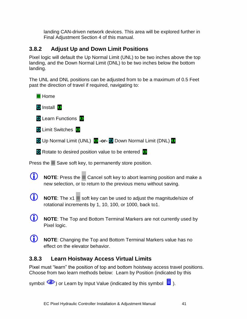
3.8.2 Adjust Up and Down Limit Positions
Pixel logic will default the Up Normal Limit (UNL) to be two inches above the top landing, and the Down Normal Limit (DNL) to be two inches below the bottom landing. The UNL and DNL positions can be adjusted from to be a maximum of 0.5 Feet past the direction of travel if required, navigating to:
Home
Install Learn Functions
Limit Switches Up Normal Limit (UNL) -or- Down Normal Limit (DNL) Rotate to desired position value to be entered Press the Save soft key, to permanently store position.
NOTE: Press the Cancel soft key to abort learning position and make a
new selection, or to return to the previous menu without saving.
NOTE: The x1 soft key can be used to adjust the magnitude/size of
rotational increments by 1, 10, 100, or 1000, back to1.
NOTE: The Top and Bottom Terminal Markers are not currently used by
Pixel logic.
NOTE: Changing the Top and Bottom Terminal Markers value has no
effect on the elevator behavior.
3.8.3 Learn Hoistway Access Virtual Limits
Pixel must “learn” the position of top and bottom hoistway access travel positions. Choose from two learn methods below: Learn by Position (indicated by this
symbol ) or Learn by Input Value (indicated by this symbol ).
EC Pixel Hydraulic Controller Installation & Adjustment Manual 42
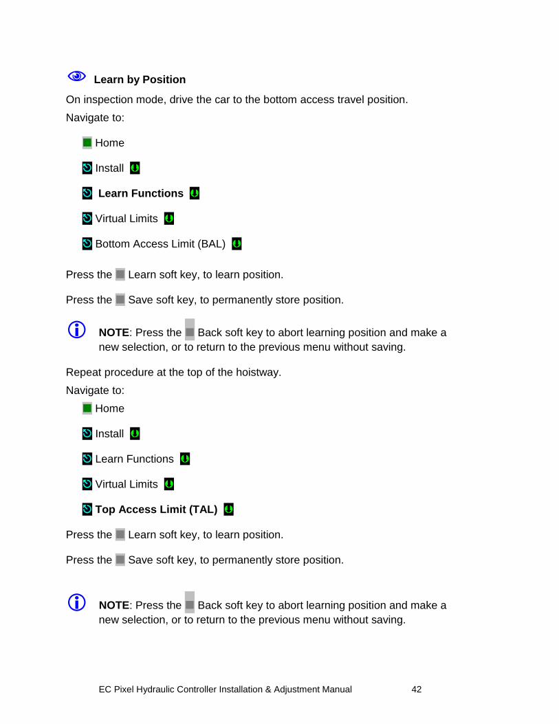
Learn by Position
On inspection mode, drive the car to the bottom access travel position.
Navigate to: Home Install Learn Functions Virtual Limits Bottom Access Limit (BAL)
Press the Learn soft key, to learn position. Press the Save soft key, to permanently store position.
NOTE: Press the Back soft key to abort learning position and make a
new selection, or to return to the previous menu without saving. Repeat procedure at the top of the hoistway.
Navigate to:
Home Install Learn Functions Virtual Limits Top Access Limit (TAL)
Press the Learn soft key, to learn position. Press the Save soft key, to permanently store position. NOTE: Press the Back soft key to abort learning position and make a
new selection, or to return to the previous menu without saving.
EC Pixel Hydraulic Controller Installation & Adjustment Manual 43
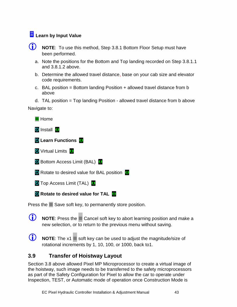
Learn by Input Value
NOTE: To use this method, Step 3.8.1 Bottom Floor Setup must have
been performed.
a. Note the positions for the Bottom and Top landing recorded on Step 3.8.1.1 and 3.8.1.2 above.
b. Determine the allowed travel distance, base on your cab size and elevator code requirements.
c. BAL position = Bottom landing Position + allowed travel distance from b above
d. TAL position = Top landing Position - allowed travel distance from b above
Navigate to: Home Install Learn Functions Virtual Limits Bottom Access Limit (BAL) Rotate to desired value for BAL position Top Access Limit (TAL) Rotate to desired value for TAL
Press the Save soft key, to permanently store position.
NOTE: Press the Cancel soft key to abort learning position and make a
new selection, or to return to the previous menu without saving.
NOTE: The x1 soft key can be used to adjust the magnitude/size of
rotational increments by 1, 10, 100, or 1000, back to1.
3.9 Transfer of Hoistway Layout
Section 3.8 above allowed Pixel MP Microprocessor to create a virtual image of the hoistway, such image needs to be transferred to the safety microprocessors as part of the Safety Configuration for Pixel to allow the car to operate under Inspection, TEST, or Automatic mode of operation once Construction Mode is
EC Pixel Hydraulic Controller Installation & Adjustment Manual 44
disable, to transfer the Safety Configuration File to SP1 and SP2 microprocessors navigate to:
Home Install File Transfer Safety Configuration Upload
NOTE: Press the Transfer soft key to transfer a configuration file safety
microprocessors or the Back soft key to abort Transfer.
NOTE: Pixel will stop all elevator functions and prompt user to wait for
transfer mode status, controller setting requirements for transfer mode will be displayed as File Transfer selection is made
3.10 Disable Construction Mode of Operation
Pixel components have now been installed and functional operation verified. You can now transition Pixel from Construction Mode to Inspection Mode. Construction mode is enabled or disabled by using the Touch & GoTM knob to navigate to: Home Install Construction Mode Disable or Cancel
NOTE: Construction Mode must be set to Disable in order to Enable any
automatic mode of operation.
EC Pixel Hydraulic Controller Installation & Adjustment Manual 45
Section 4 – Final Adjustment 4.1 Door Adjustment
The elevator door operator (or operators) should be adjusted to provide desired door performance.
a. Position the car in a convenient location within the hoistway to adjust car doors to a preliminary setting.
b. Place the car on inspection mode then follow the adjustment procedure provided by the door operator manufacturer.
NOTE: Most solid-state door control systems use adjustment procedures
that require no interaction with the elevator controller.
4.2 Check Hoistway Clearances
In order for the door operator to operate properly, all door equipment clutches, rollers, etc. must be adjusted to the correct running clearances. Make sure all hoistway and car doors for this elevator are closed and locked. Run the car the entire length of the hoistway on inspection, while riding the cartop, to be sure that the hoistway is completely clear of obstructions. View the cartop system access point to confirm that the positioning system tape and sensor head continuously track car position. Navigate to: Home Install View Selector Data
Make any necessary adjustments to tape alignment before proceeding.
4.3 Use of Test Switch
Place the TEST switch in the “Test” position (the TEST switch is located on the lower right of the P-MP board). In the test position the controller will not open doors (either front or rear) and the car will behave as on Independent Service mode of operation. Switch from inspection to normal operation. The car should travel to the closest landing.
EC Pixel Hydraulic Controller Installation & Adjustment Manual 46
NOTE: If this does not happen, view the Pixel screen from any system
access point and see if a fault condition is displayed. Consult onboard help by pressing the yellow Help key for guidance to resolve any fault that might prevent the car from moving.
The car will be ready to respond to car call demand as soon as the READY and AT FLOOR indicators are lit and the RE-LEVEL indicator is off. This confirms that the car has completed leveling at a landing. If any door opening device is active – Door Open Button, DOB, Safety Edge, SE, Photo Eye Sensor, PHE, Door Lock, Door Closed, Car Gate not closed – the car will be prevented from responding to car call demand. Observe door input status by navigating to: Home Troubleshoot Flags Door Flags Correct wiring or repair any device necessary to eliminate the active input that is preventing car movement. Refer to Section 7 – Troubleshooting in this manual for more troubleshooting assistance.
4.4 Get Car Ready to Run in Test Mode
Set the Machine Room Inspection switch located in Pixel MP Board to INSP and the TEST switch to TEST position, release the car from car top, in car, or Access inspection modes to allow it to be operated from Machine Room Inspection Mode. Set Pixel display to Home/Startup and observe for Machine Insp. and No Faults display indication, press the HELP push button for guidance in resolving any reported fault condition. Use the Pixel MP onboard Machine Room Inspection switch gear to drive the car past the bottom landing until the down terminal position of travel is reached and the display reports Down Terminal Switch Open fault. At this position verify that the car is positioned within a couple of inches below the bottom floor. Enable ETS Bypass to prevent SP1 and SP2 safety processors from triggering Slowdown Terminal Overspeed faults. Navigate to: Home Install Learn Functions
EC Pixel Hydraulic Controller Installation & Adjustment Manual 47
ETS Learn ETS Learn Up ETS Bypass Option Yes
Press the Save soft key, to enable bypass.
NOTE: Press the Cancel soft key to abort and make a new selection, or
to return to the previous menu without saving. Remove the car from Machine Insp. observe for TEST mode and No Faults display indication. Press the HELP push button for guidance in resolving any reported fault condition, and section 4.5 below to reset Non-TEST Mode of operation. The car should re-level up to the floor.
NOTE: The car will attempt to re-level into floor position once Machine
Room Inspection switches to TEST Mode of operation.
4.5 Reset Non-TEST Modes
If Pixel main window displays other Mode of operation, such as Emergency Power, Hospital Service, Fire Service, etc. such modes must be cleared to allow TEST Mode functional operation, in order to reset non latching modes of operation one must clear the mode triggering input, and for latching modes of operation such Fire Service and Earthquake Operation they can be reset by clearing the triggering inputs, then entering and exiting Construction Mode. Refer to section 3.3.11 and 3.10 to Enable or Disable Construction Mode of Operation.
NOTE: At this point Pixel‟s screen should display TEST Mode, doors
closed, and No Fault in order for the car to run in TEST Mode.
4.6 Entering Calls to Run in Test Mode
Pixel provides an Auto Call Simulation menu to allow car calls to be entered in TEST Mode. Four choices are provided in this menu as follows:
f. Up and Down from xxx to yyy, where xxx and yyy represent the landing numbers where the car will run to and from.
g. Circle xx floors around landing yyy, where xx represent the number of floors above and below the landing yyy where the car will run to and from.
h. xx floors to runs Up and Down, where xx represent the number of floors to run, one, two, etc.. floor runs up or down until the end of hoistway in the
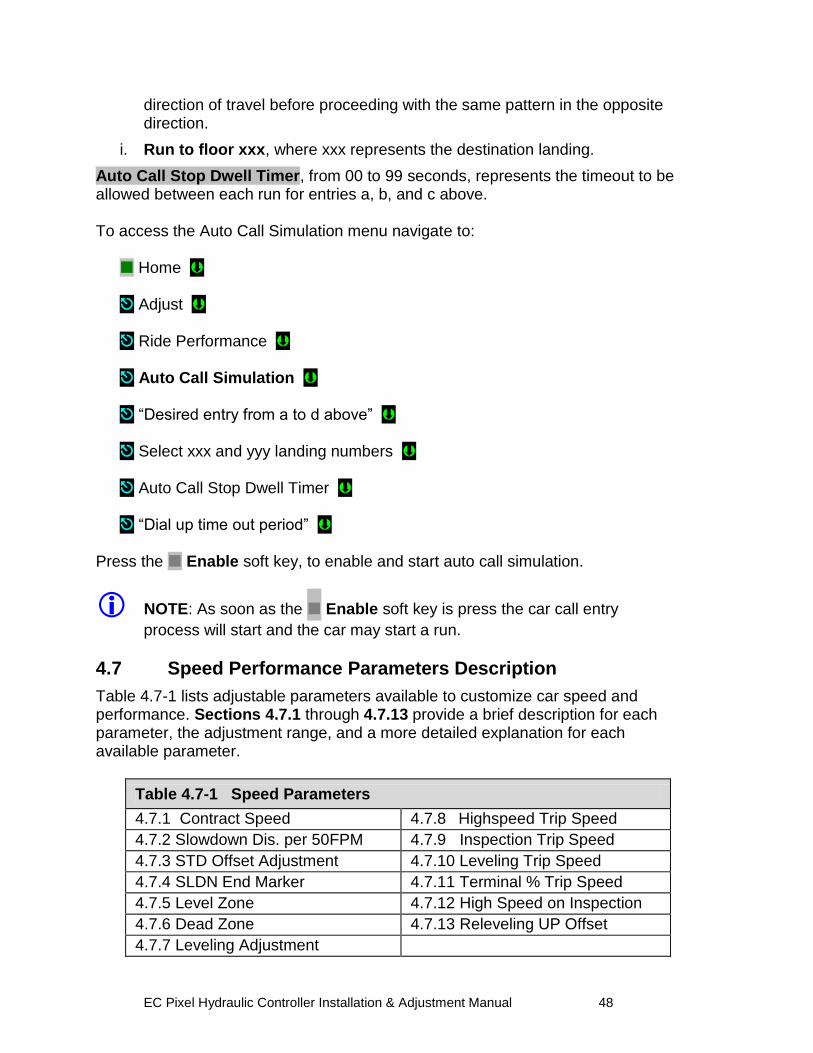
EC Pixel Hydraulic Controller Installation & Adjustment Manual 48
direction of travel before proceeding with the same pattern in the opposite direction.
i. Run to floor xxx, where xxx represents the destination landing.
Auto Call Stop Dwell Timer, from 00 to 99 seconds, represents the timeout to be allowed between each run for entries a, b, and c above. To access the Auto Call Simulation menu navigate to: Home Adjust Ride Performance Auto Call Simulation “Desired entry from a to d above” Select xxx and yyy landing numbers Auto Call Stop Dwell Timer “Dial up time out period”
Press the Enable soft key, to enable and start auto call simulation.
NOTE: As soon as the Enable soft key is press the car call entry
process will start and the car may start a run.
4.7 Speed Performance Parameters Description
Table 4.7-1 lists adjustable parameters available to customize car speed and performance. Sections 4.7.1 through 4.7.13 provide a brief description for each parameter, the adjustment range, and a more detailed explanation for each available parameter.
Table 4.7-1 Speed Parameters
4.7.1 Contract Speed 4.7.8 Highspeed Trip Speed
4.7.2 Slowdown Dis. per 50FPM 4.7.9 Inspection Trip Speed
4.7.3 STD Offset Adjustment 4.7.10 Leveling Trip Speed
4.7.4 SLDN End Marker 4.7.11 Terminal % Trip Speed
4.7.5 Level Zone 4.7.12 High Speed on Inspection
4.7.6 Dead Zone 4.7.13 Releveling UP Offset
4.7.7 Leveling Adjustment
EC Pixel Hydraulic Controller Installation & Adjustment Manual 49
4.7.1 Contract Speed
Brief Description: The Contract Speed parameter must be set to the contract speed of this car. The value is preset at the factory based on speed specified on your data sheets.
Setting Range: 25 - 1400 fpm
Default: Set to car contract speed
Units of Measure: feet per minute
Detailed Explanation: The Contract Speed parameter sets the scalevalue for all speed monitoring parameters. This parameter must be set correctly for all other speed parameters to function properly.
4.7.2 Slowdown Dist. per 50 FPM
Brief Description: Distance required for the elevator to slowdown for every 50 fpm of contract speed.
Adjustment Range: 10 – 30 Inches
Default: 12 in
Units of Measure: Inches
Detailed Explanation: Adjust parameter value up to allow more slowdown distance while decelerating into a target landing, while sacrificing performance, decrease value to improve performance
4.7.3 STD Offset Adjustment
Brief Description: Offset value added to the step down position before stepping down to the next floor to compensate for speed differential between Up and Down speeds.
Adjustment Range: 0 – 1.5 Feet
Default: 0 ft
Units of Measure: Feet
EC Pixel Hydraulic Controller Installation & Adjustment Manual 50
Detailed Explanation: With an empty cab increment parameter value to prevent car from dragging into the floors in the down direction to compensate for speed differential between Up vs. Down, Pixel will dynamically adjust value as the measured cab speed increases due to load in the cab.
4.7.4 SLDN End Marker
Brief Description: Distance from the Dead Zone center where the slowdown speed monitoring stops to give way to Leveling Speed monitoring.
Adjustment Range: 0.5 – 2.0 ft
Default: 0.5 ft
Units of Measure: feet
Detailed Explanation: Adjust parameter value up to decrease distance used for slowdown monitoring speed. Always keep value equal to or larger than Level Zone value.
4.7.5 Level Zone
Brief Description: Level Zone, or Trucking Zone, defines the Door Zone area where leveling and door operations are allowed.
Adjustment Range: 0.01 - 1.00 ft
Default: 0.5 ft
Units of Measure: feet
Detailed Explanation: Increasing the Level Zone, increases the area where door operations and leveling speed monitoring take place.
4.7.6 Dead Zone
Brief Description: Area within Door Zone, or Trucking Zone, where the car is considered to be leveled with the floor, the accuracy value is the parameter value divided by two to account for above and below the door center position.
Adjustment Range: .01 - .25 ft
Default: 0.05 ft
Units of Measure: feet
EC Pixel Hydraulic Controller Installation & Adjustment Manual 51
Detailed Explanation: Higher values in Dead Zone decreases landing accuracy, lower values increases accuracy but may generate excessive re-leveling.
4.7.7 Leveling Adjustment
Brief Description: Area outside Dead Zone where direction speed is dropped while approaching a landing to allow the car to target the floor without overshooting while keeping leveling accuracy.
Adjustment Range: .000 - .050 ft
Default: 0.000 ft
Units of Measure: feet
Detailed Explanation: Increasing the Leveling Adjustment allows more time for valves to close to prevent overshooting and re-leveling by dropping out direction prior to entering the Dead Zone.
4.7.8 Highspeed Trip Speed
Brief Description: Speed value at which the safety processors, SP1 or SP2 will declare an Overspeed condition to trigger a Contract Overspeed latching fault bringing the car to a halt.
Adjustment Range: 0001 - Contact Speed + 25%
Default: Contract Speed + 10%
Units of Measure: feet per minute
Detailed Explanation: Adjust Highspeed Trip Speed in conjunction with the high speed valves to prevent car speed from overshooting contract speed setting reaching trip threshold settings to prevent safety processors, SP1 or SP2 from declaring a Contract Overspeed latching fault.
4.7.9 Inspection Trip Speed
Brief Description: Speed value at which the safety processors, SP1 or SP2 will declare an Overspeed condition to trigger an Inspection Overspeed latching fault bringing the car to a halt.
Adjustment Range: 000 – 187 fpm
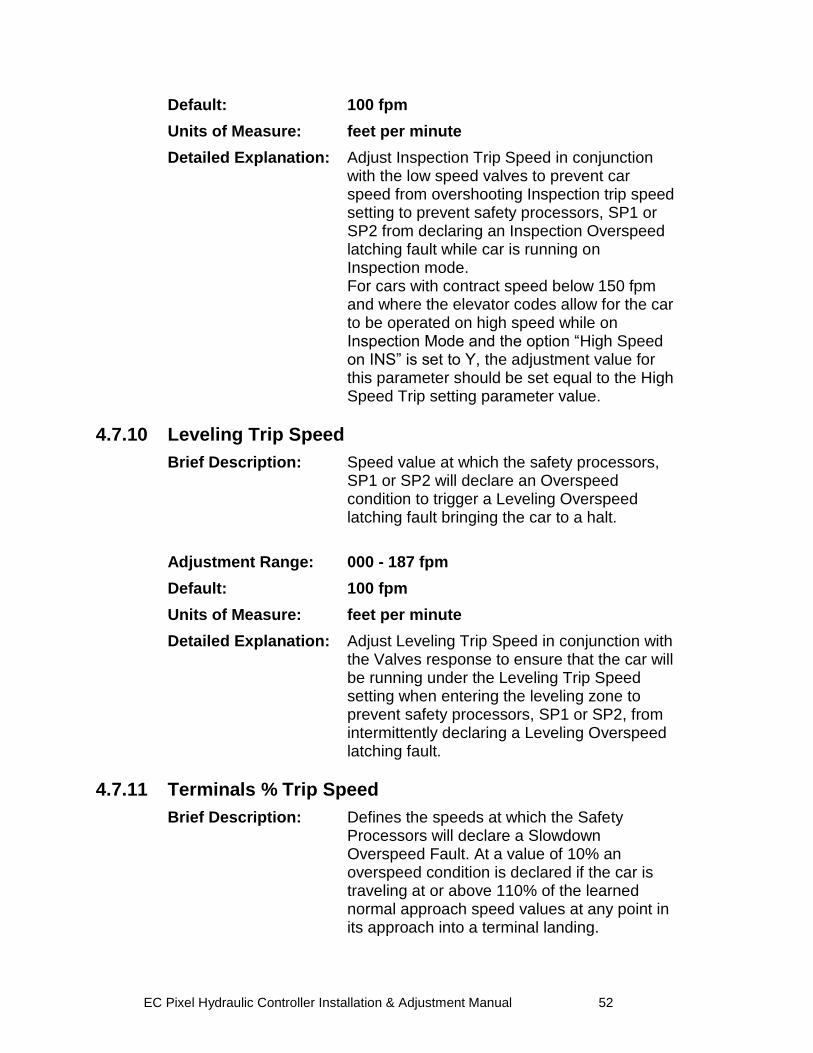
EC Pixel Hydraulic Controller Installation & Adjustment Manual 52
Default: 100 fpm
Units of Measure: feet per minute
Detailed Explanation: Adjust Inspection Trip Speed in conjunction with the low speed valves to prevent car speed from overshooting Inspection trip speed setting to prevent safety processors, SP1 or SP2 from declaring an Inspection Overspeed latching fault while car is running on Inspection mode.
For cars with contract speed below 150 fpm and where the elevator codes allow for the car to be operated on high speed while on Inspection Mode and the option “High Speed on INS” is set to Y, the adjustment value for this parameter should be set equal to the High Speed Trip setting parameter value.
4.7.10 Leveling Trip Speed
Brief Description: Speed value at which the safety processors, SP1 or SP2 will declare an Overspeed condition to trigger a Leveling Overspeed latching fault bringing the car to a halt.
Adjustment Range: 000 - 187 fpm
Default: 100 fpm
Units of Measure: feet per minute
Detailed Explanation: Adjust Leveling Trip Speed in conjunction with the Valves response to ensure that the car will be running under the Leveling Trip Speed setting when entering the leveling zone to prevent safety processors, SP1 or SP2, from intermittently declaring a Leveling Overspeed latching fault.
4.7.11 Terminals % Trip Speed
Brief Description: Defines the speeds at which the Safety Processors will declare a Slowdown Overspeed Fault. At a value of 10% an overspeed condition is declared if the car is traveling at or above 110% of the learned normal approach speed values at any point in its approach into a terminal landing.
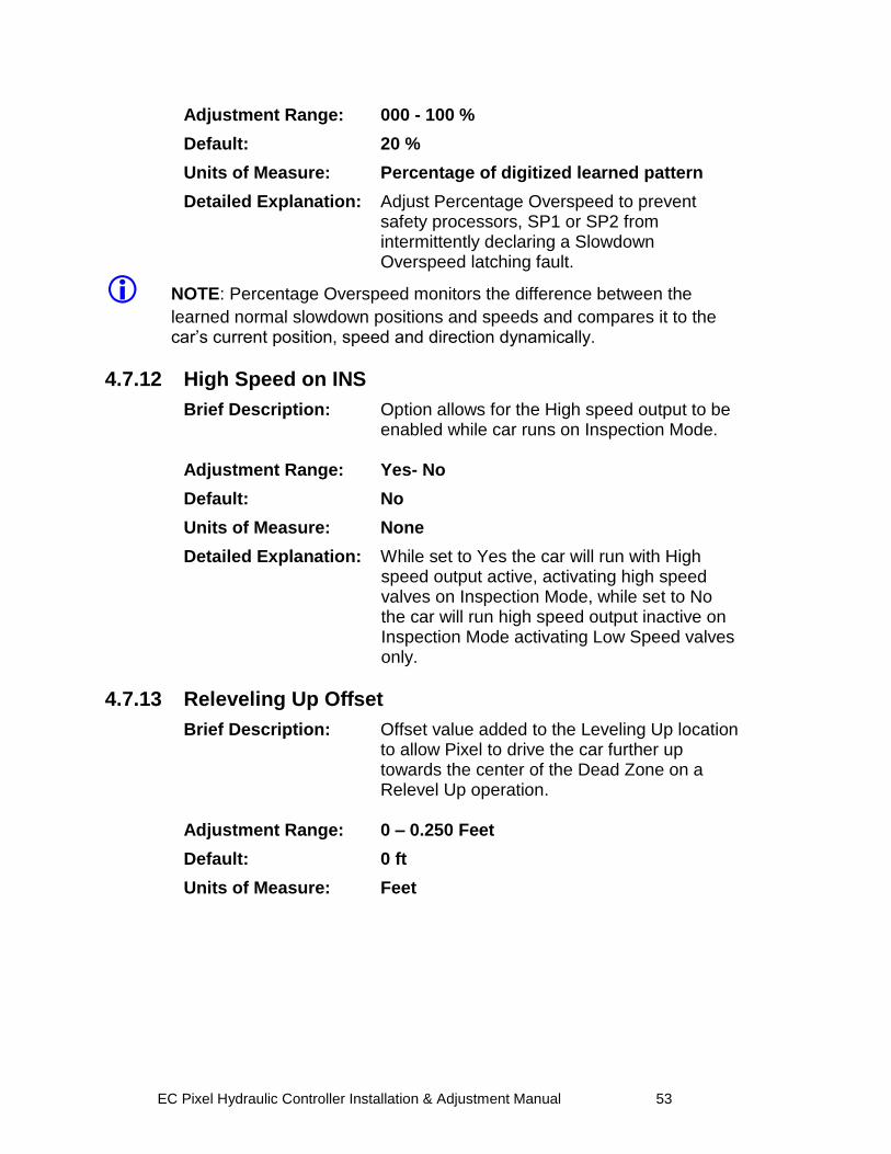
EC Pixel Hydraulic Controller Installation & Adjustment Manual 53
Adjustment Range: 000 - 100 %
Default: 20 %
Units of Measure: Percentage of digitized learned pattern
Detailed Explanation: Adjust Percentage Overspeed to prevent safety processors, SP1 or SP2 from intermittently declaring a Slowdown Overspeed latching fault.
NOTE: Percentage Overspeed monitors the difference between the
learned normal slowdown positions and speeds and compares it to the car‟s current position, speed and direction dynamically.
4.7.12 High Speed on INS
Brief Description: Option allows for the High speed output to be enabled while car runs on Inspection Mode.
Adjustment Range: Yes- No
Default: No
Units of Measure: None
Detailed Explanation: While set to Yes the car will run with High speed output active, activating high speed valves on Inspection Mode, while set to No the car will run high speed output inactive on Inspection Mode activating Low Speed valves only.
4.7.13 Releveling Up Offset
Brief Description: Offset value added to the Leveling Up location to allow Pixel to drive the car further up towards the center of the Dead Zone on a Relevel Up operation.
Adjustment Range: 0 – 0.250 Feet
Default: 0 ft
Units of Measure: Feet
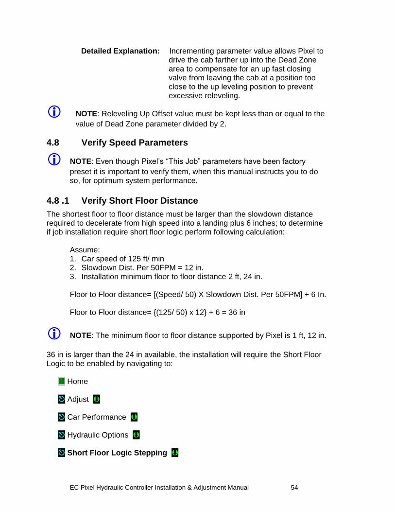
EC Pixel Hydraulic Controller Installation & Adjustment Manual 54
Detailed Explanation: Incrementing parameter value allows Pixel to drive the cab farther up into the Dead Zone area to compensate for an up fast closing valve from leaving the cab at a position too close to the up leveling position to prevent excessive releveling.
NOTE: Releveling Up Offset value must be kept less than or equal to the
value of Dead Zone parameter divided by 2.
4.8 Verify Speed Parameters
NOTE: Even though Pixel‟s “This Job” parameters have been factory
preset it is important to verify them, when this manual instructs you to do so, for optimum system performance.
4.8 .1 Verify Short Floor Distance
The shortest floor to floor distance must be larger than the slowdown distance required to decelerate from high speed into a landing plus 6 inches; to determine if job installation require short floor logic perform following calculation:
Assume: 1. Car speed of 125 ft/ min 2. Slowdown Dist. Per 50FPM = 12 in. 3. Installation minimum floor to floor distance 2 ft, 24 in.
Floor to Floor distance= [(Speed/ 50) X Slowdown Dist. Per 50FPM] + 6 In. Floor to Floor distance= {(125/ 50) x 12} + 6 = 36 in
NOTE: The minimum floor to floor distance supported by Pixel is 1 ft, 12 in.
36 in is larger than the 24 in available, the installation will require the Short Floor Logic to be enabled by navigating to: Home Adjust Car Performance Hydraulic Options Short Floor Logic Stepping
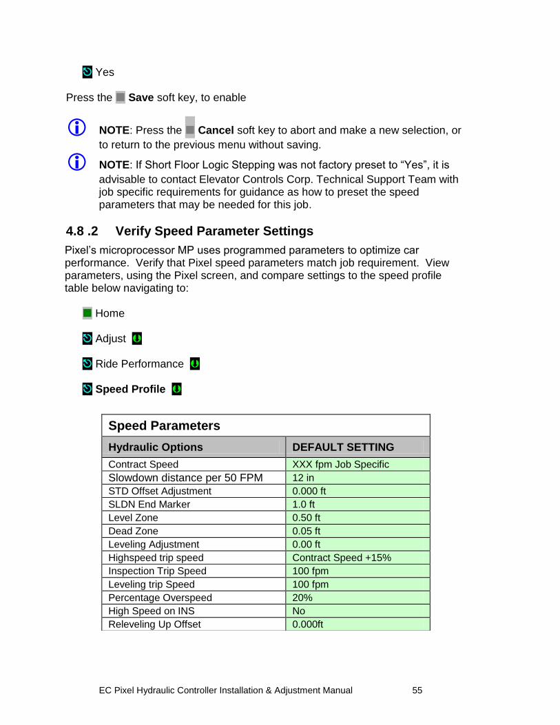
EC Pixel Hydraulic Controller Installation & Adjustment Manual 55
Yes Press the Save soft key, to enable
NOTE: Press the Cancel soft key to abort and make a new selection, or
to return to the previous menu without saving.
NOTE: If Short Floor Logic Stepping was not factory preset to “Yes”, it is
advisable to contact Elevator Controls Corp. Technical Support Team with job specific requirements for guidance as how to preset the speed parameters that may be needed for this job.
4.8 .2 Verify Speed Parameter Settings
Pixel‟s microprocessor MP uses programmed parameters to optimize car performance. Verify that Pixel speed parameters match job requirement. View parameters, using the Pixel screen, and compare settings to the speed profile table below navigating to: Home Adjust Ride Performance Speed Profile
Speed Parameters
Hydraulic Options DEFAULT SETTING
Contract Speed XXX fpm Job Specific
Slowdown distance per 50 FPM 505050fpm
12 in
STD Offset Adjustment 0.000 ft
SLDN End Marker 1.0 ft
Level Zone 0.50 ft
Dead Zone 0.05 ft
Leveling Adjustment 0.00 ft
Highspeed trip speed Contract Speed +15%
Inspection Trip Speed 100 fpm
Leveling trip Speed 100 fpm
Percentage Overspeed 20%
High Speed on INS No
Releveling Up Offset 0.000ft
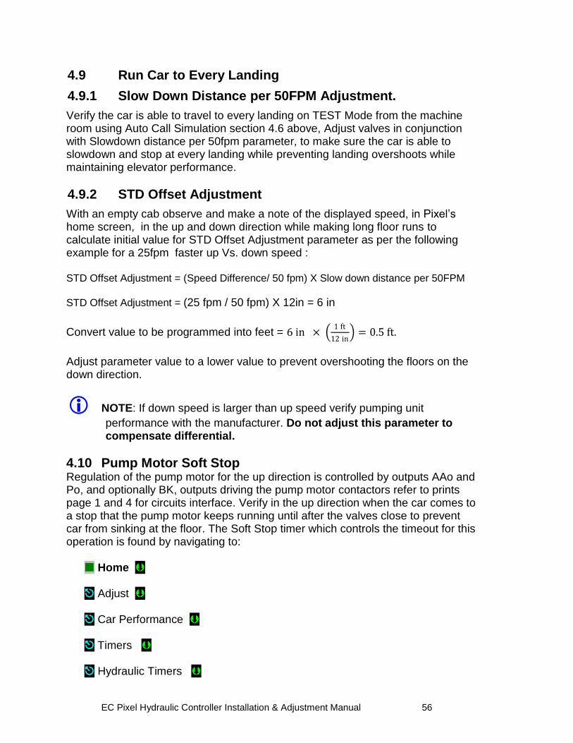
EC Pixel Hydraulic Controller Installation & Adjustment Manual 56
4.9 Run Car to Every Landing
4.9.1 Slow Down Distance per 50FPM Adjustment.
Verify the car is able to travel to every landing on TEST Mode from the machine room using Auto Call Simulation section 4.6 above, Adjust valves in conjunction with Slowdown distance per 50fpm parameter, to make sure the car is able to slowdown and stop at every landing while preventing landing overshoots while maintaining elevator performance.
4.9.2 STD Offset Adjustment
With an empty cab observe and make a note of the displayed speed, in Pixel‟s home screen, in the up and down direction while making long floor runs to calculate initial value for STD Offset Adjustment parameter as per the following example for a 25fpm faster up Vs. down speed : STD Offset Adjustment = (Speed Difference/ 50 fpm) X Slow down distance per 50FPM
STD Offset Adjustment = (25 fpm / 50 fpm) X 12in = 6 in
Convert value to be programmed into feet = 6 in × 1 ft
12 in = 0.5 ft.
Adjust parameter value to a lower value to prevent overshooting the floors on the down direction.
NOTE: If down speed is larger than up speed verify pumping unit
performance with the manufacturer. Do not adjust this parameter to compensate differential.
4.10 Pump Motor Soft Stop Regulation of the pump motor for the up direction is controlled by outputs AAo and Po, and optionally BK, outputs driving the pump motor contactors refer to prints page 1 and 4 for circuits interface. Verify in the up direction when the car comes to a stop that the pump motor keeps running until after the valves close to prevent car from sinking at the floor. The Soft Stop timer which controls the timeout for this operation is found by navigating to: Home Adjust Car Performance Timers Hydraulic Timers
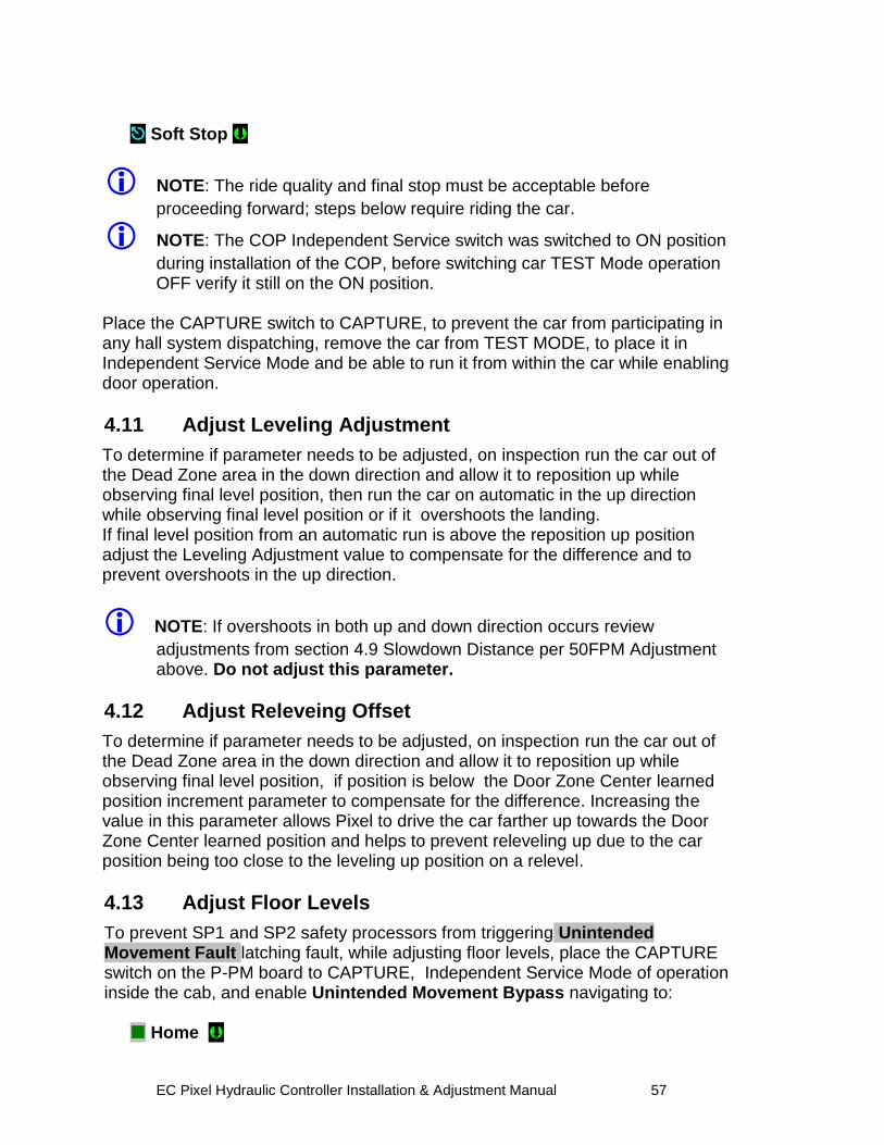
EC Pixel Hydraulic Controller Installation & Adjustment Manual 57
Soft Stop
NOTE: The ride quality and final stop must be acceptable before
proceeding forward; steps below require riding the car.
NOTE: The COP Independent Service switch was switched to ON position
during installation of the COP, before switching car TEST Mode operation OFF verify it still on the ON position.
Place the CAPTURE switch to CAPTURE, to prevent the car from participating in any hall system dispatching, remove the car from TEST MODE, to place it in Independent Service Mode and be able to run it from within the car while enabling door operation.
4.11 Adjust Leveling Adjustment
To determine if parameter needs to be adjusted, on inspection run the car out of the Dead Zone area in the down direction and allow it to reposition up while observing final level position, then run the car on automatic in the up direction while observing final level position or if it overshoots the landing. If final level position from an automatic run is above the reposition up position adjust the Leveling Adjustment value to compensate for the difference and to prevent overshoots in the up direction.
NOTE: If overshoots in both up and down direction occurs review
adjustments from section 4.9 Slowdown Distance per 50FPM Adjustment above. Do not adjust this parameter.
4.12 Adjust Releveing Offset
To determine if parameter needs to be adjusted, on inspection run the car out of the Dead Zone area in the down direction and allow it to reposition up while observing final level position, if position is below the Door Zone Center learned position increment parameter to compensate for the difference. Increasing the value in this parameter allows Pixel to drive the car farther up towards the Door Zone Center learned position and helps to prevent releveling up due to the car position being too close to the leveling up position on a relevel.
4.13 Adjust Floor Levels
To prevent SP1 and SP2 safety processors from triggering Unintended Movement Fault latching fault, while adjusting floor levels, place the CAPTURE switch on the P-PM board to CAPTURE, Independent Service Mode of operation inside the cab, and enable Unintended Movement Bypass navigating to: Home
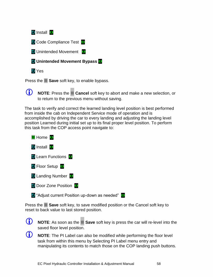
EC Pixel Hydraulic Controller Installation & Adjustment Manual 58
Install Code Compliance Test Unintended Movement Unintended Movement Bypass Yes
Press the Save soft key, to enable bypass.
NOTE: Press the Cancel soft key to abort and make a new selection, or
to return to the previous menu without saving. The task to verify and correct the learned landing level position is best performed from inside the cab on Independent Service mode of operation and is accomplished by driving the car to every landing and adjusting the landing level position Learned during initial set up to its final proper level position. To perform this task from the COP access point navigate to:
Home Install Learn Functions Floor Setup Landing Number Door Zone Position “Adjust current Position up-down as needed”
Press the Save soft key, to save modified position or the Cancel soft key to reset to back value to last stored position.
NOTE: As soon as the Save soft key is press the car will re-level into the
saved floor level position.
NOTE: The PI Label can also be modified while performing the floor level
task from within this menu by Selecting PI Label menu entry and manipulating its contents to match those on the COP landing push buttons.
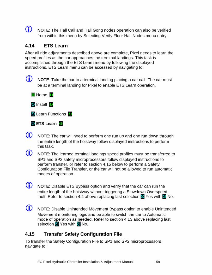
EC Pixel Hydraulic Controller Installation & Adjustment Manual 59
NOTE: The Hall Call and Hall Gong nodes operation can also be verified
from within this menu by Selecting Verify Floor Hall Nodes menu entry.
4.14 ETS Learn
After all ride adjustments described above are complete, Pixel needs to learn the speed profiles as the car approaches the terminal landings. This task is accomplished through the ETS Learn menu by following the displayed instructions. ETS Learn menu can be accessed by navigating to:
NOTE: Take the car to a terminal landing placing a car call. The car must
be at a terminal landing for Pixel to enable ETS Learn operation. Home Install Learn Functions ETS Learn
NOTE: The car will need to perform one run up and one run down through
the entire length of the hoistway follow displayed instructions to perform this task.
NOTE: The learned terminal landings speed profiles must be transferred to
SP1 and SP2 safety microprocessors follow displayed instructions to perform transfer, or refer to section 4.15 below to perform a Safety Configuration File Transfer, or the car will not be allowed to run automatic modes of operation.
NOTE: Disable ETS Bypass option and verify that the car can run the
entire length of the hoistway without triggering a Slowdown Overspeed fault. Refer to section 4.4 above replacing last selection Yes with No.
NOTE: Disable Unintended Movement Bypass option to enable Unintended
Movement monitoring logic and be able to switch the car to Automatic mode of operation as needed. Refer to section 4.13 above replacing last selection Yes with No.
4.15 Transfer Safety Configuration File
To transfer the Safety Configuration File to SP1 and SP2 microprocessors navigate to:
EC Pixel Hydraulic Controller Installation & Adjustment Manual 60
Home Install File Transfer
NOTE: Pixel will stop all elevator functions and prompt user to wait for
transfer mode status, controller setting requirements for transfer mode will be displayed as File Transfer selection is made
Safety Configuration Upload
Press the Transfer soft key to transfer a configuration file to safety microprocessors or the Back soft key to abort transfer.
NOTE: Through this procedure Pixel will prompt you to wait while the
system enters and exits file transfer mode operation. Do not press any keys during a wait timeout to prevent file transfer corruptions. Wait for Pixel to confirm that it is ready to receive dashboard command.
.
4.16 Verify Overall Car Performance Pixel car controller must be operating to desired performance, verify and correct following operations:
a. Position Indicator displays proper landing labels.
b. Car calls can be entered through the COP push buttons.
c. Every push button in the COP performs its function Door Open, Door Close, Passing Gong Enable, etc.
d. Car Responds to all capable Hall Calls.
e. Hall and Car gongs performance.
f. Overall car functionality and performance.
NOTE: If any speed parameter or learned parameter is modified the MP
will display an error indicating Safety configuration mismatch requiring to execute a Safety Configuration File Transfer to SP1 and SP2 microprocessors, refer to section 4.12 above to perform this task, or the car will not be allowed to run on automatic mode of operation.
WARNING: Safety tests sections 5 and 6 below, overall car function
performance, and all local safety inspections must be completed before releasing car to public.
EC Pixel Hydraulic Controller Installation & Adjustment Manual 61
Section 5 – Speed Monitoring Adjustment 5.1 Car Speed Monitoring System
The Pixel Elevator Controller – working in conjunction with the Landa™ dual head positioning unit – monitors the position and speed of the elevator throughout the entire hoistway. The Landa™ Positioning System provides actual car position “on demand” (absolute position is read from the Landa™ Encoded Tape) and car speed is calculated based upon change in car position over a time interval.
The SP1 and SP2 safety processors individually read the Landa™ Positioning System at a rate of approximately once every 10 milliseconds for current car position. The Landa™ Positioning System includes dual sensor heads. These redundant heads continuously read encoded tape and position information from each which is compared against the other for validation (“Main Tape Position” and “Auxiliary Tape Position”). A free-running timer is used to provide an accurate measure of the time between position samples, which is used to calculate car speed as follows:
Cab speed = ∆position ÷ ∆time, where ∆position = (previous cab position) – (current cab position)
∆time = (previous cab position time) – (current cab position time)
5.1.1 Defining Overspeed
Pixel‟s SP1 and SP2 safety processors monitor car speed at all times to detect car speeds in excess of the car‟s programmed speeds, including overspeed conditions as the car approaches the terminal landings. To determine if the speed of the car is normal or an overspeed as the car approaches either terminal landing, Pixel‟s main computer learns the landing zone for each floor during the hoistway position learning process. It also learns the “normal speed profile” that is executed as the car approaches the terminal landings in order to compare the two. The normal speed profile is learned from the moment the car begins its deceleration process to the final stop at the terminal landing. Both up and down terminal deceleration profiles are learned and stored. The learn process once performed and verified during elevator installation will be transferred and permanently stored by the three microprocessors that make up the Pixel controller‟s main processing unit (MP, SP1, SP2). The learn process must be accomplished and transferred before the car can be run on any passenger automatic mode of operation (otherwise the car is only allowed to run on Inspection Operation).
EC Pixel Hydraulic Controller Installation & Adjustment Manual 62
5.1.2 Monitoring Overspeed
Pixel‟s SP1 and SP2 safety processors independently monitor the following overspeed conditions:
a. Elevator Highspeed Trip Speed elevator cab speed exceeds programmed Contract trip speed.
b. Inspection Trip Speed elevator cab speed exceeds 150 ft-min or programmed Inspection trip speed, whichever is less.
c. Leveling Trip Speed elevator cab speed exceeds 150 ft-min or programmed Leveling trip speed within the landing leveling zone, whichever is less
d. Terminals % Trip Speed elevator cab speed in the direction of travel exceeds learned terminal speed profile plus programmed % trip speed.
NOTE: Speed monitoring final adjustments should be performed only after
elevator speed performance has been attained. It must be readjusted following any speed parameter change.
NOTE: Confirm that Pixel‟s main screen displays contract speed and speed
performance correctly before proceeding with final speed monitor adjustments.
5.1.3 Speed Monitoring Adjustment
NOTE: Place the car in TEST Mode of operation before proceeding
with speed monitoring adjustments.
Pixel speed monitoring parameters are part of the Speed Profile group and can be accessed by navigating to: Home Install Initial Settings Speed Profile High Speed Trip Speed (entry 14 of 20) Set to contract speed value plus 10% OR
EC Pixel Hydraulic Controller Installation & Adjustment Manual 63
Inspection Speed Trip Speed (entry 15 of 20) Set to Inspection Speed times two, up to a maximum value of 150 ft/min. OR Leveling Trip Speed (entry 16 of 20) Set to Leveling Speed times 10, up to a maximum value of 150 ft/min.
OR Terminal’s % Trip Speed (entry 18 of 20) Set Terminal‟s % Trip Speed parameter to 10% then run the car from the top to the bottom landing, increment % value as needed to prevent car from tripping Slowdown Overspeed Fault.
Press the Save soft key, to save modified speed trip value or the Cancel soft key to abort speed monitoring value change. Run the car to confirm that revised settings do not cause a speed monitoring fault. If Speed Monitoring Trips are occurring as the car runs, adjust the corresponding trip speed value in conjunction with valves unit to prevent speed overshoots.
NOTE: Verification of Speed Monitoring will be performed in Code
Compliance Verification Section 6 following.
NOTE: If any speed parameter or learned parameter is modified the MP
will display an error indicating Safety configuration mismatch requiring to execute a Safety Configuration File Transfer to SP1 and SP2 microprocessors, refer to section 4.12 above to perform this task, or the car will not be allowed to run on automatic mode of operation.
EC Pixel Hydraulic Controller Installation & Adjustment Manual 64
Section 6 – Code Compliance Verification A17.1/B44 Elevator Safety Tests & Inspection
6.1 Performing Elevator Safety Tests & Inspections
WARNING: Safety tests should be performed by a QUALIFIED
ADJUSTER OR SERVICE PERSONNEL. A helper should always be present and prepared to turn off the main line disconnect to remove power from the elevator if needed when the car is run with safety switches bypassed. PROCEED WITH CAUTION.
CAUTION: Perform each test procedure below only after the elevator
system has been adjusted and verified to comply with job performance requirements and transfer of final safety configuration data from the MP to the SP1 and SP2 processors has been performed.
NOTE: The following procedure is intended as a guide while performing
periodic inspection and safety tests of the elevator system. Please refer to the Safety Code for Elevators and all applicable local codes for specific requirements.
6.2 Intentionally Left Blank
6.3 Intentionally Left Blank
6.4 Safety Speed Tests
6.4.1 Car Buffer Test – Fully Loaded Car
The Pixel Car Buffer test is accomplished using a simple menu driven process and the procedure below:
a. Set CAPTURE switch, located on the MP board, to CAPTURE which will prevent the car from servicing Hall Calls.
b. Place full load test weights in the car.
c. Drive the car to the top landing by entering a Car Call.
d. Set TEST switch, located on the MP board, to TEST which will enable Test Mode operation and disable door operation.
e. Turn off main power to the controller.
f. Place jumpers from controller terminals, 4A to SAFC (Car Safety), and 4A to SAFH (Hoistway Safety), to bypass safety switches for the Car Buffer Test.
g. Turn on main power to the controller.
EC Pixel Hydraulic Controller Installation & Adjustment Manual 65
h. Navigate to: Home Install Code Compliance Tests Safeties Speed Tests Car Buffer ETS Bypass Option Set ETS Bypass Option to Yes
Press the Save soft key to Save ETS Bypass Option selection or Cancel to abort test. Press the Run Test soft key to start the Car Buffer test run or the Back soft key to abort test run.
CAUTION: Once the Run Test soft key has been pressed, the car will
accelerate to contract speed in the down direction until the car strikes the car buffer. Once the car strikes the car buffer, flip the controller inspection switch to the INSP position to stop
i. Inspect the mechanical condition of the cab to ensure the car can be returned to service.
j. Using Controller Inspection, run the car up past the bottom landing door zone area. Remove all jumpers placed in item f above.
k. Reset ETS Bypass option, ETS Bypass Option, Set to No
l. Toggle the TEST switch to the off position and remove test weights from the car.
m. Set the CAPTURE switch to off, which will enable the car to service hall calls and return to Automatic Mode operation.
6.4.2 Intentionally Left Blank
6.4.3 Intentionally Left Blank
EC Pixel Hydraulic Controller Installation & Adjustment Manual 66
6.4.4 Terminal Stopping Devices (A17.1Section 3.25)
Pixel provides menu driven procedures to verify the operation of the Terminal (up and down) Stopping Devices as detailed in sections 6.4.4.1 and 6.4.4.2 below.
6.4.4.1 Normal Terminal Stopping Devices (A17.1 Section 3.25.2) Terminal Speed Reducing Devices “Emergency terminal Stop Test “
NOTE: This test verifies failure to reduce speed at terminal landing even do
Landa position system is functioning properly.
The Emergency Terminal Stop test forces the car to run on high speed pass slowdown position into a terminal landing (up or down) to verify that even do the Landa Position system is working properly the car speed will be used by the safety processors to stop the car before reaching terminal landing position, the tests is accomplished using the menu driven procedure below:
a. Set CAPTURE switch, located on the MP board, to CAPTURE which will prevent the car from servicing Hall Calls.
b. Drive the car to a terminal landing by entering a Car Call.
c. Set TEST switch, located on the MP board, to TEST which will enable Test Mode operation and disable door operation.
d. Navigate to:
Home Install Code Compliance Tests Safeties Speed Tests Emergency Terminal Stop
NOTE: The Emergency Terminal Stop parameter “Slowdown Position”
represents the hoistway position at which the car must start its deceleration into the bottom landing (relative to the down normal limit).
Press the Run Test soft key to start the Emergency Terminal Stop test run or the Back soft key to abort test run.
EC Pixel Hydraulic Controller Installation & Adjustment Manual 67
CAUTION: Once the Run Test soft key has been pressed, the car will
accelerate to contract speed in the down direction and run past the Slowdown Position.
e. Observe that the Display shows a Slowdown Overspeed Trip latching
fault, and that the car comes to a halt.
f. Press the System Fault Reset key to clear the fault and enable the car to re-level into the top or bottom landing.
g. Repeat test for opposite direction of travel as required
n. Set place the TEST and CAPTURE switches to off, which will enable the car to accept hall calls and return to Automatic Mode operation.
6.4.4.2 Terminal Speed Reducing Devices (A17.1 Section 3.25.1) Normal Terminal Stopping Devices “ NTS Slowdown Test”
NOTE: This test verifies failure of Normal means to slowdown the car into a
terminal landing, Landa Main Sensor Head and Elevator microprocessor, using the safety microprocessors to declare a fault and allow the car to level with the floor utilizing Landa Auxiliary Sensor Head only.
The NTS Slowdown test forces the car to execute an emergency slowdown into a terminal landing (up or down) utilizing the Landa Auxiliary sensor head only to verify that the failure of the primary terminal slowdown device does not prevent the car from landing into terminal landing position, the test is accomplished using the menu driven procedure below:
a. Set CAPTURE switch, located on the MP board, to CAPTURE which will prevent the car from servicing Hall Calls.
b. Set TEST switch, located on the MP board, to TEST which will enable Test Mode operation and disable door operation.
c. Drive the car to a terminal landing by entering a Car Call.
d. Navigate to:
Home Install Code Compliance Tests Safeties Speed Tests NTS Slowdown Test
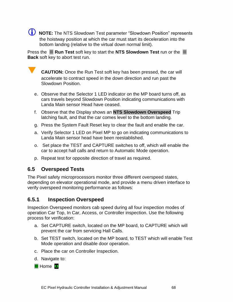
EC Pixel Hydraulic Controller Installation & Adjustment Manual 68
NOTE: The NTS Slowdown Test parameter “Slowdown Position” represents
the hoistway position at which the car must start its deceleration into the bottom landing (relative to the virtual down normal limit).
Press the Run Test soft key to start the NTS Slowdown Test run or the Back soft key to abort test run.
CAUTION: Once the Run Test soft key has been pressed, the car will
accelerate to contract speed in the down direction and run past the Slowdown Position.
e. Observe that the Selector 1 LED indicator on the MP board turns off, as
cars travels beyond Slowdown Position indicating communications with Landa Main sensor Head have ceased.
f. Observe that the Display shows an NTS Slowdown Overspeed Trip latching fault, and that the car comes level to the bottom landing.
g. Press the System Fault Reset key to clear the fault and enable the car.
a. Verify Selector 1 LED on Pixel MP to go on indicating communications to Landa Main sensor head have been reestablished.
o. Set place the TEST and CAPTURE switches to off, which will enable the car to accept hall calls and return to Automatic Mode operation.
p. Repeat test for opposite direction of travel as required.
6.5 Overspeed Tests
The Pixel safety microprocessors monitor three different overspeed states, depending on elevator operational mode, and provide a menu driven interface to verify overspeed monitoring performance as follows:
6.5.1 Inspection Overspeed
Inspection Overspeed monitors cab speed during all four inspection modes of operation Car Top, In Car, Access, or Controller inspection. Use the following process for verification:
a. Set CAPTURE switch, located on the MP board, to CAPTURE which will prevent the car from servicing Hall Calls.
b. Set TEST switch, located on the MP board, to TEST which will enable Test Mode operation and disable door operation.
c. Place the car on Controller Inspection.
d. Navigate to:
Home
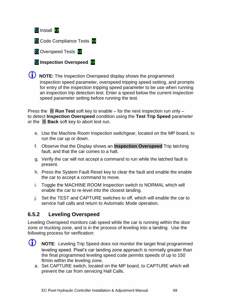
EC Pixel Hydraulic Controller Installation & Adjustment Manual 69
Install Code Compliance Tests Overspeed Tests Inspection Overspeed
NOTE: The Inspection Overspeed display shows the programmed
inspection speed parameter, overspeed tripping speed setting, and prompts for entry of the inspection tripping speed parameter to be use when running an inspection trip detection test. Enter a speed below the current inspection speed parameter setting before running the test.
Press the Run Test soft key to enable – for the next inspection run only – to detect Inspection Overspeed condition using the Test Trip Speed parameter or the Back soft key to abort test run.
e. Use the Machine Room Inspection switchgear, located on the MP board, to
run the car up or down.
f. Observe that the Display shows an Inspection Overspeed Trip latching fault, and that the car comes to a halt.
g. Verify the car will not accept a command to run while the latched fault is present.
h. Press the System Fault Reset key to clear the fault and enable the enable the car to accept a command to move.
i. Toggle the MACHINE ROOM Inspection switch to NORMAL which will enable the car to re-level into the closest landing.
j. Set the TEST and CAPTURE switches to off, which will enable the car to service hall calls and return to Automatic Mode operation.
6.5.2 Leveling Overspeed
Leveling Overspeed monitors cab speed while the car is running within the door zone or trucking zone, and is in the process of leveling into a landing. Use the following process for verification:
NOTE: Leveling Trip Speed does not monitor the target final programmed
leveling speed. Pixel‟s car landing zone approach is normally greater than the final programmed leveling speed code permits speeds of up to 150 ft/min within the leveling zone.
a. Set CAPTURE switch, located on the MP board, to CAPTURE which will prevent the car from servicing Hall Calls.
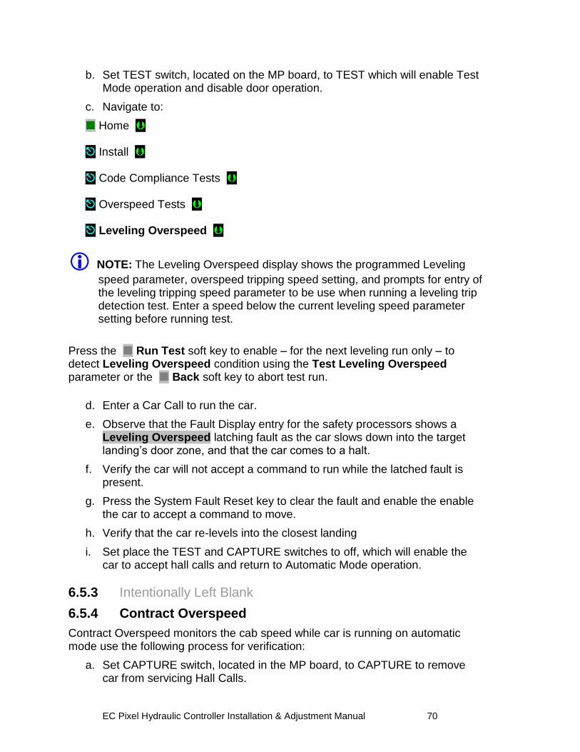
EC Pixel Hydraulic Controller Installation & Adjustment Manual 70
b. Set TEST switch, located on the MP board, to TEST which will enable Test Mode operation and disable door operation.
c. Navigate to:
Home Install Code Compliance Tests Overspeed Tests Leveling Overspeed
NOTE: The Leveling Overspeed display shows the programmed Leveling
speed parameter, overspeed tripping speed setting, and prompts for entry of the leveling tripping speed parameter to be use when running a leveling trip detection test. Enter a speed below the current leveling speed parameter setting before running test.
Press the Run Test soft key to enable – for the next leveling run only – to detect Leveling Overspeed condition using the Test Leveling Overspeed parameter or the Back soft key to abort test run.
d. Enter a Car Call to run the car.
e. Observe that the Fault Display entry for the safety processors shows a Leveling Overspeed latching fault as the car slows down into the target landing‟s door zone, and that the car comes to a halt.
f. Verify the car will not accept a command to run while the latched fault is present.
g. Press the System Fault Reset key to clear the fault and enable the enable the car to accept a command to move.
h. Verify that the car re-levels into the closest landing
i. Set place the TEST and CAPTURE switches to off, which will enable the car to accept hall calls and return to Automatic Mode operation.
6.5.3 Intentionally Left Blank
6.5.4 Contract Overspeed
Contract Overspeed monitors the cab speed while car is running on automatic mode use the following process for verification:
a. Set CAPTURE switch, located in the MP board, to CAPTURE to remove car from servicing Hall Calls.
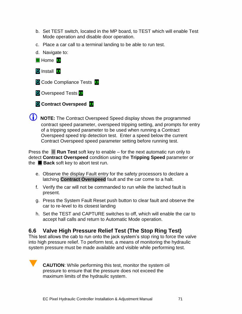
EC Pixel Hydraulic Controller Installation & Adjustment Manual 71
b. Set TEST switch, located in the MP board, to TEST which will enable Test Mode operation and disable door operation.
c. Place a car call to a terminal landing to be able to run test.
d. Navigate to:
Home Install Code Compliance Tests Overspeed Tests Contract Overspeed
NOTE: The Contract Overspeed Speed display shows the programmed
contract speed parameter, overspeed tripping setting, and prompts for entry of a tripping speed parameter to be used when running a Contract Overspeed speed trip detection test. Enter a speed below the current Contract Overspeed speed parameter setting before running test.
Press the Run Test soft key to enable – for the next automatic run only to detect Contract Overspeed condition using the Tripping Speed parameter or the Back soft key to abort test run.
e. Observe the display Fault entry for the safety processors to declare a latching Contract Overspeed fault and the car come to a halt.
f. Verify the car will not be commanded to run while the latched fault is present.
g. Press the System Fault Reset push button to clear fault and observe the car to re-level to its closest landing
h. Set the TEST and CAPTURE switches to off, which will enable the car to accept hall calls and return to Automatic Mode operation.
6.6 Valve High Pressure Relief Test (The Stop Ring Test) This test allows the cab to run onto the jack system‟s stop ring to force the valve into high pressure relief. To perform test, a means of monitoring the hydraulic system pressure must be made available and visible while performing test.
CAUTION: While performing this test, monitor the system oil pressure to ensure that the pressure does not exceed the maximum limits of the hydraulic system.
EC Pixel Hydraulic Controller Installation & Adjustment Manual 72
To perform test:
a. Set CAPTURE switch, located in the MP board, to CAPTURE to remove car from servicing Hall Calls.
b. Set TEST switch, located in the MP board, to TEST which will enable Test Mode operation and disable door operation.
c. With the car on Automatic or Inspection, position the car at or near the top Landing
d. With the doors closed, place the car in Controller Inspection mode.
e. Set car in Construction mode of operation navigate to:
Home Install Construction Mode
Press the Enable soft key to enable to place car in construction mode
f. Inch the car UP on Controller Inspection until the car contacts the stop ring. Once there, continue to inch the car up until the valve goes into pressure relief.
g. Note the oil pressure reading.
h. Run the car DOWN on Controller Inspection at or below the top floor landing.
i. Remove the car from Construction mode using the process on “e” above but now press the Disable soft key to exit construction mode.
j. Set CAPTURE switch, located in the MP board, to off to return car to servicing Hall Calls.
6.7 Intentionally Left Blank
6.8 Landa™ Redundant Position System Verification
Critical Component: Landa™ Main and Auxiliary Position Sensor Heads
Redundant Component: Landa™ Main and Auxiliary Position Sensor Heads
Monitored Component: Car Speed, and Position
NOTE: The following tests verify that Pixel can safely position the cab using
either of the two independent sensor heads that comprise the Landa™ positioning system.
The Pixel control uses a dual head positioning system system – Landa™– incorporating a positional encoded tape that runs the entire length of the hoistway.
EC Pixel Hydraulic Controller Installation & Adjustment Manual 73
This system enables each either sensor head to provide absolute position information independent of the other. Refer to page 6 of the prints for Landa™ interface circuits.
The Main Positioning head communicates its absolute position to the main processor via dedicated RS485 serial port while the Auxiliary Positioning head communicates its absolute position to the main processor via CAN.
The Landa™ positioning system verifies absolute cab position to 0.032” (0.8mm) accuracy throughout the entire length of the hoistway.
The Pixel computer network, MPU, will “learn” and then build a positional image of the entire hoistway including:
Door Zone or Trucking Zone, one per landing
Top and Bottom Access Limits
Mid hoistway position
Physical open position for the top and bottom normal limit switches
A speed profile deceleration ramp for the top and bottom landings
NOTE: The landing zones are limited to a maximum of six inches plus or
minus learned position and are set at a factory default of three inches.
The learn process – once performed and verified during elevator installation – will be transferred and permanently stored by the three microprocessors that make up the Pixel controller‟s main processing unit (MP, SP1, SP2). The learn process must be accomplished and transferred before the car can be run on any passenger automatic mode of operation.
NOTE: Pixel always “knows” the car position by reading it from the encoded
tape and validating it through comparison to the learned/stored positional image.
Verification of Landa™ Main Sensor Head:
a. Set CAPTURE switch, located on the MP board, to CAPTURE which will prevent the car from responding to hall call demand.
b. Set TEST switch, located on the MP board, to TEST which will enable Test Mode operation and disable door operation.
c. Enter a car call to a floor several floors away from current car position (if two stop elevator place a call to the other floor).
d. While car is running, unplug the Main Selector RJ45 cable labeled “SELECTOR” from Pixel MP, and observe that Pixel displays a Main
EC Pixel Hydraulic Controller Installation & Adjustment Manual 74
Selector Fault, makes an emergency slowdown, and positions the elevator cab at the next available landing.
e. Pixel will remove the car from service until proper Landa™ Main sensor head communication is re-established.
f. Verify that the car will not respond to car calls.
g. Reconnect the RJ45 cable at the Pixel MP. Confirm that Pixel clears the Main Selector Fault, and that the car to respond to car call demand.
h. Return the CAPTURE and TEST switches to their off positions, which will enable the car to return to Automatic Mode of operation and serve hall call demand.
Verification of Landa™ Auxiliary Sensor Head:
a. Set CAPTURE switch, located on the MP board, to CAPTURE, which will prevent the car from responding to hall call demand.
b. Set TEST switch, located on the MP board, to TEST which will enable Test Mode operation and disable door operation.
c. Enter a car call to a floor several floors away from current car position (if two stop elevator place a call to the other floor).
d. While car is running, unplug the cable labeled “CAB CAN” from the Pixel MP, and observe that Pixel displays Aux. Selector Fault, makes an emergency slowdown, and positions the elevator cab at the next available landing.
e. Pixel will remove the car from service until proper Landa™ Auxiliary sensor head communication is re-established.
f. Verify that the car will not respond to car calls.
g. Reconnect the RJ45 cable at the Pixel MP. Confirm that Pixel clears the Aux. Selector Fault, and that the car to respond to car call demand.
h. Return the CAPTURE and TEST switches to their off positions, which will enable the car to return to Automatic Mode of operation and serve hall call demand.
6.9 Monitoring Compliance Verification Monitoring Critical Circuits ASME 17.1 Sections 2.26.9.3 and 2.26.9.4
6.9.1 EB1-EB2 and EBX1-EBX2 Relays Contacts Critical Component: EB1-EB2 and EBX1-EBX2 Relay Contacts
Redundant Component: RG1-RG2 and RGBP1-RGBP2, SP1 and SP2 Computer Monitoring Inputs
Monitored Component: EB1-EB2 and EBX1-EBX2 Relay Contacts
EC Pixel Hydraulic Controller Installation & Adjustment Manual 75
NOTE: Test verifies that Pixel can detect failure of Emergency Brake relay
contacts to open and responds by preventing car motion. Refer to page 2 of prints for Emergency Brake circuits.
a. Set CAPTURE switch, located on the MP board, to CAPTURE which will
prevent the car from responding to hall call demand.
b. Set TEST switch, located on the MP board, to TEST which will enable Test Mode operation and disable door operation.
c. Place Machine Room Inspection switch to INSP.
NOTE: EB1-EB2 and EBX1-EBX2 Relays Contacts Verification functions
identically in both inspection and automatic modes of operation.
d. Momentarily short RG to RGBP inputs by using a jumper to bridge pin 3 to pin 4 on the PDB board at the JSMP harness connector.
e. Verify that the Pixel screen displays EB Relay Fault or EBX Relays Fault, the EB1-EB2 and EBX1-EBX2 relays are off, and the Emergency brake sets.
f. Verify that the car will not accept a run command while the fault is present.
g. Cycle power and confirm that the fault condition has not been cleared.
h. Press the System Fault Reset button to clear the fault condition. Verify that either the EB1-EB2 or EBX1-EBX2 relays activate and that the car will accept a run command.
i. Set the TEST and CAPTURE switches to off, which will enable the car to accept hall calls and return to Automatic Mode operation.
j. Place Machine Room Inspection switch to NORMAL.
NOTE: Pixel alternates use of EB1-EB2 and EBX1-EBX2 relay contacts,
that provide power to the emergency brake circuits, at the end of every run. Proper contact opening operation is verified prior to allowing the next run.
NOTE: Section 6.9.2 applies only for control units utilizing mechanical
starters and section 6.9.3 only if mechanical starters are used in Wye-Delta configuration, skip to section 6.94 if control uses solid state starter.
6.9.2 AA Motor Contactor Force Guided Relay
Critical Component: AA Relay
Redundant Component: STOP1-STOP2, SP1 and SP2 Computer Monitoring Inputs
Monitored Component: AA Relay Contacts
EC Pixel Hydraulic Controller Installation & Adjustment Manual 76
NOTE: Test confirms that Pixel correctly detects a motor contactor or solid
state motor contactor pilot relay failure to open. Pixel checks for a stuck contact at the end of every run before allowing the next run. Refer to page 1and 4 of prints.
a. Set CAPTURE switch, located on the MP board, to CAPTURE which will
prevent the car from responding to hall call demand.
b. Set TEST switch, located on the MP board, to TEST which will enable Test Mode operation and disable door operation.
c. Place Machine Room Inspection switch to INSP.
NOTE: AA Contactor Verification functions identically in both inspection and
automatic modes of operation. d. Manually press and hold the AA contactor, or AA solid state pilot force
guided relay movable and verify that the Pixel screen displays AA Relay Fault. Then release and confirm that the fault condition has been cleared (screen displays No Faults).
e. While holding AA contactor movable , use Controller Inspection to command the car Up or Down.
f. Verify that the car will not accept a run command while the fault is present.
g. Release the AA contactor movable and confirm that the Pixel screen displays No Faults.
h. Return the Controller Inspection, TEST and CAPTURE switches to their off positions, which will enable the car to return to Automatic Mode of operation and serve call demand
Place Machine Room Inspection switch to NORMAL.
6.9.3 P Potential Force Guided Relay (Y-Delta Starters Only)
Critical Component: P Relay
Redundant Component: Pin1-Pin2, SP1 and SP2 Computer Monitoring Inputs
Monitored Component: P Relay Contacts
NOTE: Test confirms that Pixel correctly detects a P relay, “used as the Y
starter”, failure to open. Pixel checks for a stuck contact at the end of every run before allowing the next run. refer to page 1 and 4 of prints. P contactor is one of two force-guided relays that provide power to the brake circuits.
EC Pixel Hydraulic Controller Installation & Adjustment Manual 77
a. Set CAPTURE switch, located on the MP board, to CAPTURE which will prevent the car from responding to hall call demand.
b. Set TEST switch, located on the MP board, to TEST, which will enable Test Mode operation and disable door operation.
c. Place Machine Room Inspection switch to INSP.
NOTE: P Relay Verification functions identically in both inspection and
automatic modes of operation.
d. Manually press and hold the P relay movable and verify that the Pixel screen displays P Relay Fault. Then release and observe that the fault condition has been cleared (screen displays No Faults).
e. While holding P relay movable, use Machine Room Inspection to command the car Up or Down.
f. Verify that the car will not accept a run command while the fault is present.
g. Release the P contactor actuator and confirm that the Pixel screen displays No Faults.
h. Return the Controller Inspection, TEST and CAPTURE switches to their off positions, which will enable the car to return to Automatic Mode of operation and serve call demand.
i. Place Machine Room Inspection switch to NORMAL.
NOTE: Section 6.9.4 applies only for control units using auxiliary redundant
mechanical starter, skip to section 6.94 if control does not uses it.
6.9.4 BK Force Guided Relay (Redundant Mechanical Starter)
Critical Component: BK Relay
Redundant Component: BKI1-BKI2, SP1 and SP2 Computer Monitoring Inputs
Monitored Component: BK Relay Contacts
NOTE: Test confirms that Pixel correctly detects a BK relay, used as
redundant starter if required, failure to open. Pixel checks for a stuck contact at the end of every run before allowing the next run. Refer to page 1 and 4 of prints.
a. Set CAPTURE switch, located on the MP board, to CAPTURE which will
prevent the car from responding to hall call demand.
b. Set TEST switch, located on the MP board, to TEST, which will enable Test Mode operation and disable door operation.
EC Pixel Hydraulic Controller Installation & Adjustment Manual 78
c. Place Machine Room Inspection switch to INSP.
NOTE: BK Relay Verification functions identically in both inspection and
automatic modes of operation.
d. Manually press and hold the BK relay movable and verify that the Pixel screen displays BK Relay Fault. Then release and observe that the fault condition has been cleared (screen displays No Faults).
e. While holding BK relay movable, use Machine Room Inspection to command the car Up or Down.
f. Verify that the car will not accept a run command while the fault is present.
g. Release the BK contactor actuator and confirm that the Pixel screen displays No Faults.
h. Return the Controller Inspection, TEST and CAPTURE switches to their off positions, which will enable the car to return to Automatic Mode of operation and serve call demand.
i. Place Machine Room Inspection switch to NORMAL.
6.9.5 Hoistway & Car Door Bypass Switches
Critical Component: Hoistway and Car Door Bypass Switches
Redundant Component: HDB1-HDB2 and CDB1-CDB2, and SP1 and SP2 Computer Monitoring Inputs
Monitored Component: Hall and Car Door Bypass Switches
NOTE: This test verifies that Pixel will only allow the car to operate in Cartop
or In Car Inspection modes under the following conditions: (1) Hoistway bypass switch is on BYPASS; (2) Car Door Bypass switch is on BYPASS; (3) both are on BYPASS.
Hoistway Door Bypass Switch:
a. While the car is on Automatic Mode of Operation, place the Hoistway Door Bypass switch to the BYPASS position.
b. Confirm that the Pixel screen displays Inspection Mode and also a Hall Door Bypass w/o Inspection fault.
c. Verify that the car will not respond to a car or hall call demand, and will not move in Controller or Access inspection modes.
d. Place the controller on Cartop Inspection and verify that the car will respond to an up or down cartop inspection command with any hoistway door in the not fully closed position.
EC Pixel Hydraulic Controller Installation & Adjustment Manual 79
e. With a hoistway door still in the not fully closed position, place the Hoistway Door Bypass switch to OFF position. Verify that the car will not respond to an up or down cartop inspection command.
f. Fully close the test door. Verify that the car will now respond to an up or down cartop inspection command.
Car Door Bypass Switch:
a. While the car is on Automatic Mode of Operation, place the Car Door Bypass switch to the BYPASS position.
b. Confirm that the Pixel screen displays Inspection Mode and also a Car Door Bypass w/o Inspection fault.
c. Verify that the car will not respond to a car or hall call demand, and will not move in Controller or Access inspection modes.
d. Place the controller on Cartop Inspection and verify that the car will respond to an up or down cartop inspection command with the car door in the not fully closed position.
e. With the car door still in the not fully closed position, place the Car Door Bypass switch to OFF position. Verify that the car will not respond to an up or down cartop inspection command.
f. Fully close the car door. Verify that the car will now respond to an up or down cartop inspection command.
Hoistway and Car Door Bypass Switches:
a. While the car is on Automatic Mode of Operation, place the Hoistway and Car Door Bypass switches to the BYPASS position.
b. Confirm that the Pixel screen displays Inspection Mode and also a Hoistway Door Bypass w/o Inspection fault.
c. Verify that the car will not respond to a car or hall call demand, and will not move in Controller or Access inspection modes.
d. Place the controller on Cartop Inspection and verify that the car will respond to an up or down cartop inspection command with any hoistway and car door in the not fully closed position.
e. With any hoistway and car door still in the not fully closed position, place the Car Door Bypass switch to OFF position. Verify that the car will not respond to an up or down cartop inspection command.
f. Fully close the hoistway doors and car door. Verify that the car will now respond to an up or down cartop inspection command.
NOTE: Referring to page MP of job prints, observe that both Hoistway and
Car Door Bypass switches are being monitored on the Normally Open and The Normally Closed sides of their respective contacts. If the input state of
EC Pixel Hydraulic Controller Installation & Adjustment Manual 80
SP1 and SP2 are not opposite, a Car Door Bypass System Fault or Hoistway Door Bypass System Fault will be displayed on the Pixel screen and the car will be prevented from moving.
6.9.6 Detection of Jumpers on Door Safety String
Critical Component: Car Gate and Hoistway Door Locks Redundant Component: SP1 and SP2 computer Monitoring Inputs
Monitored Inputs: Front Doors: CGF1-CGF2, DLAT1-DLAT2, DLSF1-DLSF2, DLAB1-DLAB2
Additional inputs for front and rear doors Rear Doors: CGR1-CGR2, DLSR1-DLSR2,
NOTE: Test verifies that Pixel will detect jumpers placed on the door safety
string and prevent doors from closing and any car movement. Refer to page 4 of the prints for job required door safety string inputs.
a. Place the car on Independent Service and run the car to the bottom landing. Car will automatically open the doors.
b. Place the car on Independent Service and run the car to the bottom landing. Car will automatically open the doors
c. Place a jumper from 4A to CGF. Confirm that the Pixel screen displays Door Lock System Fault.
d. Verify that the car will not respond to a car call demand.
e. Remove jumper from 4A to CGF. Confirm that the Pixel screen displays No Faults.
f. Place a jumper from 4A to DLAB. Confirm that the Pixel screen with displays Door Lock System Fault.
g. Verify that the car will not respond to a car call demand.
h. Remove jumper from 4A to DLAB. Confirm that the Pixel screen displays No Faults.
i. Run the car to an intermediate landing.
j. Place a jumper from 4A to DLSF. Confirm that the Pixel screen displays Door Lock System Fault.
k. Verify that the car will not respond to a car call demand.
l. Remove jumper from 4A to DLSF. Confirm that the Pixel screen displays No Faults.
m. Run the car to the top landing.
n. Place a Jumper from 4A to DLAT. Confirm that the Pixel screen displays Door Lock System Fault.
EC Pixel Hydraulic Controller Installation & Adjustment Manual 81
o. Verify that the car will not respond to a car call demand.
p. Remove Jumper from 4A to DLAT. Confirm that the Pixel screen displays No Faults.
NOTE: Skip to step w below if car has no rear doors.
q. Run the car to a rear door landing and open the rear doors.
r. Place a jumper from 4A to CGR. Confirm that the Pixel screen displays Door Lock System Fault.
s. Verify that the car will not respond to a car call demand.
t. Remove jumper from 4A to CGR. Confirm that the Pixel screen displays No Faults.
u. Place a jumper from 4A to DLSR. Confirm that the Pixel screen displays Door Lock System Fault.
v. Verify that the car will not respond to a car call demand.
w. Remove jumper from 4A to DLSR. Confirm that the Pixel screen displays No Fault
x. Release car from Independent service.
6.9.7 Door Open and Close Simultaneously
Critical Component: Door Open & Door Close Limits
Redundant Component: DOL and DCL Computer Monitoring Inputs
Monitored Component: Door Opened & Door Close Limits
NOTE: Test verifies that Pixel will detect a condition where the door open
and door close limit switches are opened simultaneously.
a. Call the car to the closest landing to the machine room and place it in Independent service, to command it to open the doors
b. Place the Capture switch to Capture and the Car Door and Hoistway Door Bypass switches to Bypass on Pixel MP board
c. Gain access to the top of the car and place it on Car Top inspection.
d. Turn main power to the controller off.
e. Remove and isolate the wire from the DCLF terminal on the P-TOC board.
f. Remove the car from Car Top Inspection and place the Hoistway Door Bypass switches on Pixel MP board to off possition
g. Turn main power to the controller on, car will proceed to close its doors and to reposition to the closest landing and open the doors.
EC Pixel Hydraulic Controller Installation & Adjustment Manual 82
h. Confirm that the Pixel screen displays Front Door Limit Switches Fault.
i. Verify that doors will not close by pressing the door close button in the COP.
j. Place the car on Cartop Inspection.
k. Reconnect wire to the DCLF terminal.
l. Remove car from Cartop Inspection. Confirm that the Pixel screen displays No Faults.
m. Remove Car from Independent Service. Confirm that doors operate normally.
NOTE: Repeat for rear doors if car has front and rear door operation. Use
DCLR and DOLR in place of DOLF and DCLF to perform steps above.
6.9.8 Valves Latched Direction
6.9.8.1 U Relay Contact 1 Critical Component: U relay contact 1 normally open
Redundant Component: URM1-URM2, SP1 and SP2 Computer Monitoring Inputs
Monitored Component: U relay contact 1 normally open
NOTE: Test confirms that Pixel correctly detects an up contact 1 relay failure
to open possible leaving the up low speed directional valve on. Pixel checks for a stuck contact at the end of every run before allowing the next run. Refer to page 1 of prints.
a. Set CAPTURE switch, located on the MP board, to CAPTURE which will prevent the car from responding to hall call demand.
b. Set TEST switch, located on the MP board, to TEST, which will enable Test Mode operation and disable door operation.
c. Place Machine Room Inspection switch to INSP.
NOTE: U Relay contact 1 Verification functions identically in both inspection
and automatic modes of operation.
d. Manually close the U relay using the relay manual levering flap, observe the Pixel screen displays U Relay Fault and drops EB1-EB1X- EBX1-EBX2 relays removing power from the valves circuits and starter units.
e. Release manual levering flap and observe that the fault condition remains
f. Verify that the car will not accept a run command while the fault is present.
g. Cycle power and confirm that the fault condition has not been cleared.
EC Pixel Hydraulic Controller Installation & Adjustment Manual 83
h. Press the System Fault Reset button to clear the fault condition. Verify that either the EB1-EB2 or EBX1-EBX2 relays activate and that the car will accept a run command.
i. Set the TEST and CAPTURE switches to off, which will enable the car to accept hall calls and return to Automatic Mode operation.
j. Place Machine Room Inspection switch to NORMAL.
6.9.8.2 D Relay Contact 1
Critical Component: D relay contact 1 normally open
Redundant Component: DRM1-DRM2, SP1 and SP2 Computer Monitoring Inputs
Monitored Component: D relay contact 1 normally open
NOTE: Test confirms that Pixel correctly detects a down contact 1 relay
failure to open possible leaving the down low speed directional valve on. Pixel checks for a stuck contact at the end of every run before allowing the next run. Refer to page 1 of prints.
a. Set CAPTURE switch, located on the MP board, to CAPTURE which will prevent the car from responding to hall call demand.
b. Set TEST switch, located on the MP board, to TEST, which will enable Test Mode operation and disable door operation.
c. Place Machine Room Inspection switch to INSP.
NOTE: D Relay contact 1 Verification functions identically in both inspection
and automatic modes of operation.
d. Manually close the D relay using the relay manual levering flap, observe the Pixel screen displays D Relay Fault and drops EB1-EB1X- EBX1-EBX2 relays removing power from the valves circuits and starter units.
e. Release manual levering flap and observe that the fault condition remains
f. Verify that the car will not accept a run command while the fault is present.
g. Cycle power and confirm that the fault condition has not been cleared.
h. Press the System Fault Reset button to clear the fault condition. Verify that either the EB1-EB2 or EBX1-EBX2 relays activate and that the car will accept a run command.
i. Set the TEST and CAPTURE switches to off, which will enable the car to accept hall calls and return to Automatic Mode operation.
j. Place Machine Room Inspection switch to NORMAL.
EC Pixel Hydraulic Controller Installation & Adjustment Manual 84
6.9.9 Single Ground
Critical Component: N/A
Redundant Component: F4A Fuse
Monitored Component: N/A
Test Verification of Single Ground:
a. Place the car on Machine Room Inspection.
NOTE: The Single Ground Test can be performed on either automatic or
inspection operation.
NOTE: The system logic is driven by a source of 110 Volts AC, and has
one side already connected to ground, the 3 buss. The other side, the 4A buss, is protected by a fuse feeding the logic power. Any accidental grounding will result in a blown fuse F4A, which will remove controller power to the safety string and logic circuits.
b. Short terminal SAFH to ground. Verify that fuse F4A blows, and the Pixel
screen displays Safety String Open Fault.
c. Turn main power to controller off.
d. Replace fuse F4A.
e. Turn main power to controller on.
f. Confirm that the Pixel screen displays No Faults.
g. Remove the car from Machine Room Inspection.
6.9.10 Permit Car Speeds Over 150 fpm ASME 2.26.9.3.c except 2.26.1.5.10(b)
Critical Component: Landa™ Main and Auxiliary Selectors
Redundant Component: Landa™ Main and Auxiliary Selectors
Monitored Component: Car Speed
NOTE: Refer to Section 6.6, Landa™ Redundant Position System
Verification, for verification of the speed and position feedback system.
NOTE: Refer to Section 6.3.1, Inspection Overspeed and 6.3.2 Leveling
Overspeed, for verification of inspection and leveling overspeed.
EC Pixel Hydraulic Controller Installation & Adjustment Manual 85
Section 7 – Troubleshooting The Elevator Controls Microprocessor Controller is the most reliable part of any elevator system. While problems are possible, the most efficient troubleshooting approach is to first look to the “outside world” for the source of malfunctions that most frequently take elevators out of service.
7.1 General Troubleshooting Tips.
Pixel controller is equipped with multiple indicators designed to help troubleshoot at a glance; significant time and frustration can be avoided by simply paying attention to the indicators on the MP and P-I/O boards.
7.2 General Checklist
a. The Pixel home screen always displays the most prominent fault preventing the car from Automatic operation.
NOTE: If an active fault is displayed, pressing the HELP button will
display the fault help screen and possible corrective action. Refer to section 7.3 below for example of fault and HELP diagnostics navigation.
b. Verify that each power control step-down transformer has the correct input and output voltages (refer to job prints page 2 for terminal and fuse numbers). Replace fuses as necessary.
c. Verify that the 24 VDC power supply module green LED is illuminated, and that voltage output is within 10 % tolerance. If not, check the following:
i. Verify input power to the power supply. ii. Check the power supply input switch setting, set per job prints page 2. iii. Verify that fuses FSP1 and FSP2 are good.
d. Check voltage between terminals 4A and 3 to confirm approximately 110 VAC.
e. Check voltage between terminals 6 and 3; 50 and 3; and 50F and 3. Confirm approximately 24 VDC. If any of the above power supply voltages are not within range, check the appropriate fuses.
NOTE: System common is the 3 buss (normally terminal 3 is connected to
chassis ground). Unless otherwise noted, all DC voltages are measured with respect to Terminal 3.
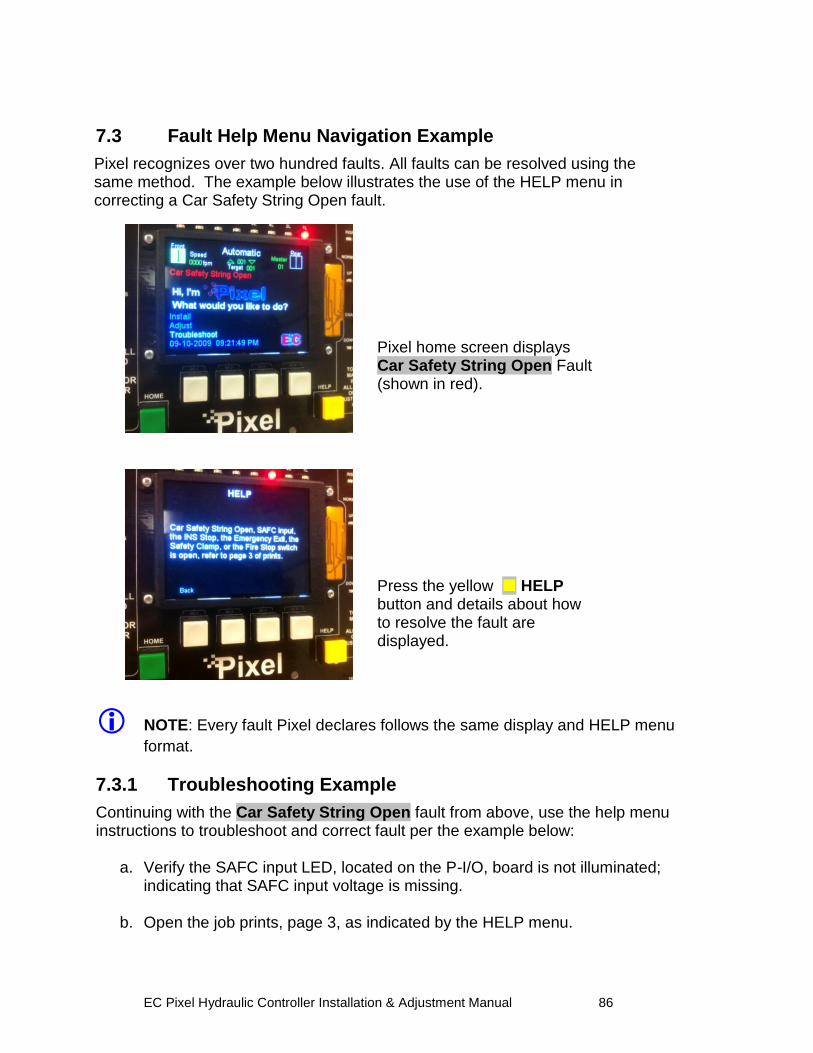
EC Pixel Hydraulic Controller Installation & Adjustment Manual 86
7.3 Fault Help Menu Navigation Example
Pixel recognizes over two hundred faults. All faults can be resolved using the same method. The example below illustrates the use of the HELP menu in correcting a Car Safety String Open fault.
Pixel home screen displays Car Safety String Open Fault (shown in red). Press the yellow HELP button and details about how to resolve the fault are displayed.
NOTE: Every fault Pixel declares follows the same display and HELP menu
format.
7.3.1 Troubleshooting Example
Continuing with the Car Safety String Open fault from above, use the help menu instructions to troubleshoot and correct fault per the example below:
a. Verify the SAFC input LED, located on the P-I/O, board is not illuminated; indicating that SAFC input voltage is missing.
b. Open the job prints, page 3, as indicated by the HELP menu.
EC Pixel Hydraulic Controller Installation & Adjustment Manual 87
c. Verify that power between terminals 3 and 4A is approximately 120 VAC. For example purposes, consider that voltage measured is within range. Power supply voltage troubleshooting is covered in Section 7.2 above, General Check List.
d. Verify that power between terminals 3 and SAFC is not present.
e. Verify that the COP Fire Panel Stop Switch is closed, and power between terminals 3 to 20B is approximately 120 VAC inside the COP. For example purposes the Fire Panel Stop Switch is closed and the voltage measured is within range.
f. Access the top of the car, and place the car on Cartop Inspection mode.
g. Verify that the power between terminals 3 and 20B at the TOC terminal strip is approximately 120 VAC.
h. Determine which device is open between terminals 20B and SAFC in the TOC terminal strip. Correct as required.
i. Verify power between terminals 3 and SAFC is approximately 120 VAC on the TOC terminal strip.
j. Verify voltage at the controller traveler terminal strip SAFC and SAFC LED is illuminated on the P-I/O board.
k. Press HOME to return to Pixel main menu and verify fault has cleared.
NOTE: Some faults are latching and require that the RESET System
Fault Reset button be pressed to clear fault after it is no longer present. Refer to Table 7.3.1 below for a list of latching faults requiring manual reset.
l. If another fault is displayed, follow steps 1 to 11 above to correct and return the car to service.
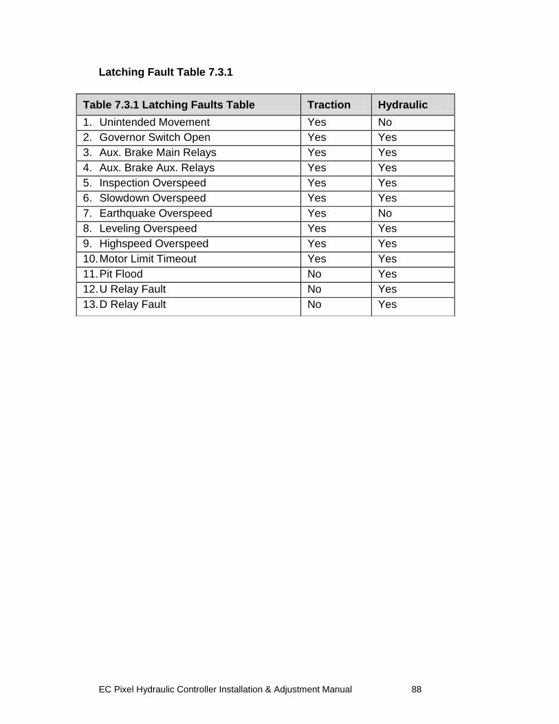
EC Pixel Hydraulic Controller Installation & Adjustment Manual 88
Latching Fault Table 7.3.1
Table 7.3.1 Latching Faults Table Traction Hydraulic
1. Unintended Movement Yes No
2. Governor Switch Open 3.
Yes Yes
3. Aux. Brake Main Relays Yes Yes
4. Aux. Brake Aux. Relays Yes Yes
5. Inspection Overspeed
Yes Yes
6. Slowdown Overspeed Yes Yes
7. Earthquake Overspeed Yes No
8. Leveling Overspeed Yes Yes
9. Highspeed Overspeed Yes Yes
10. Motor Limit Timeout Yes Yes
11. Pit Flood No Yes
12. U Relay Fault No Yes
13. D Relay Fault No Yes

EC Pixel Hydraulic Controller Installation & Adjustment Manual 89
Section 8 – Intentionally Left Blank
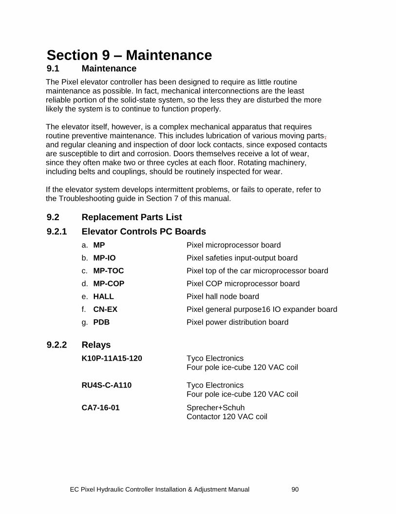
EC Pixel Hydraulic Controller Installation & Adjustment Manual 90
Section 9 – Maintenance 9.1 Maintenance
The Pixel elevator controller has been designed to require as little routine maintenance as possible. In fact, mechanical interconnections are the least reliable portion of the solid-state system, so the less they are disturbed the more likely the system is to continue to function properly. The elevator itself, however, is a complex mechanical apparatus that requires routine preventive maintenance. This includes lubrication of various moving parts, and regular cleaning and inspection of door lock contacts, since exposed contacts are susceptible to dirt and corrosion. Doors themselves receive a lot of wear, since they often make two or three cycles at each floor. Rotating machinery, including belts and couplings, should be routinely inspected for wear. If the elevator system develops intermittent problems, or fails to operate, refer to the Troubleshooting guide in Section 7 of this manual.
9.2 Replacement Parts List
9.2.1 Elevator Controls PC Boards
a. MP Pixel microprocessor board
b. MP-IO Pixel safeties input-output board
c. MP-TOC Pixel top of the car microprocessor board
d. MP-COP Pixel COP microprocessor board
e. HALL Pixel hall node board
f. CN-EX Pixel general purpose16 IO expander board
g. PDB Pixel power distribution board
9.2.2 Relays
K10P-11A15-120 Tyco Electronics Four pole ice-cube 120 VAC coil RU4S-C-A110 Tyco Electronics Four pole ice-cube 120 VAC coil
CA7-16-01 Sprecher+Schuh Contactor 120 VAC coil
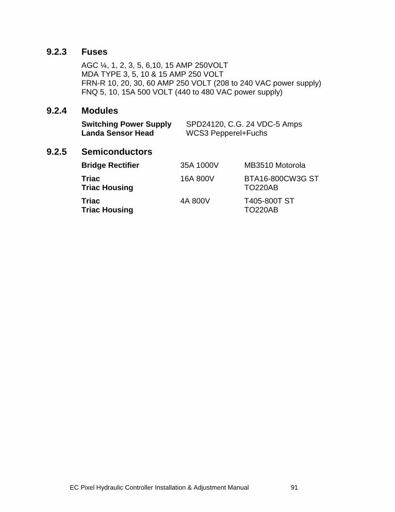
EC Pixel Hydraulic Controller Installation & Adjustment Manual 91
9.2.3 Fuses
AGC ¼, 1, 2, 3, 5, 6,10, 15 AMP 250VOLT MDA TYPE 3, 5, 10 & 15 AMP 250 VOLT FRN-R 10, 20, 30, 60 AMP 250 VOLT (208 to 240 VAC power supply) FNQ 5, 10, 15A 500 VOLT (440 to 480 VAC power supply)
9.2.4 Modules
Switching Power Supply SPD24120, C.G. 24 VDC-5 Amps Landa Sensor Head WCS3 Pepperel+Fuchs
9.2.5 Semiconductors
Bridge Rectifier 35A 1000V MB3510 Motorola
Triac 16A 800V BTA16-800CW3G ST Triac Housing TO220AB
Triac 4A 800V T405-800T ST Triac Housing TO220AB