PITT-11-16-035 Project Number 112IC05958 …files.dep.state.pa.us/ProgramIntegration/PA Pipeline...
165
Tetra Tech 661 Andersen Drive, Pittsburgh, PA 15220-2700 Tel 412.921.7090 Fax 412.921.4040 www.tetratech.com PITT-11-16-035 December 2, 2016 Project Number 112IC05958 Mr. Nathan R. Crawford, P.E. Permits Section Chief Department of Environmental Protection Waterways and Wetlands – Southcentral Regional Office 909 Elmerton Avenue Harrisburg, PA 17110 Re: Pennsylvania Pipeline Project Permit No. ESG 0300015002 Construction Spreads 3, 4, & 5 Technical Deficiency Response Dear Mr. Crawford: On behalf of our client, Sunoco Pipeline, L.P. (SPLP), Tetra Tech, Inc. provides the following responses to the Pennsylvania Department of Environmental Protection (DEP) Technical Deficiency Response letter dated September 6, 2016 regarding the above-referenced ESCGP-2 Permit Application. The supporting attachments represent a revision of the ESCGP-2 Application in response to the comments received and also incorporates revisions that have been made to the project design since the original submission. For ease of your review, each DEP item is set forth bolded verbatim below, followed by an italicized narrative response. Comments and Responses to September 6, 2016 Technical Deficiency Response Page 2 General Common Technical Deficiencies 1. DEP The application will need a comprehensive Preparedness Prevention Contingency (PPC) and private well plan. Regarding these plans 25 Pa Code §102.5W: a. The application includes separate documents covering PPC activities. Due to the scope of this project, you must consolidate these plans into one stand-alone document that can be used in the field. This plan must also be consistent in your Joint Permit Applications submitted for this project.
Transcript of PITT-11-16-035 Project Number 112IC05958 …files.dep.state.pa.us/ProgramIntegration/PA Pipeline...

Tetra Tech661 Andersen Drive, Pittsburgh, PA 15220-2700
Tel 412.921.7090 Fax 412.921.4040 www.tetratech.com
PITT-11-16-035
December 2, 2016
Project Number 112IC05958
Mr. Nathan R. Crawford, P.E.Permits Section ChiefDepartment of Environmental ProtectionWaterways and Wetlands – Southcentral Regional Office909 Elmerton AvenueHarrisburg, PA 17110
Re: Pennsylvania Pipeline Project Permit No. ESG 0300015002Construction Spreads 3, 4, & 5Technical Deficiency Response
Dear Mr. Crawford:
On behalf of our client, Sunoco Pipeline, L.P. (SPLP), Tetra Tech, Inc. provides the following responses tothe Pennsylvania Department of Environmental Protection (DEP) Technical Deficiency Response letterdated September 6, 2016 regarding the above-referenced ESCGP-2 Permit Application. The supportingattachments represent a revision of the ESCGP-2 Application in response to the comments received andalso incorporates revisions that have been made to the project design since the original submission.
For ease of your review, each DEP item is set forth bolded verbatim below, followed by an italicizednarrative response.
Comments and Responses to September 6, 2016 Technical Deficiency ResponsePage 2General Common Technical Deficiencies1. DEP The application will need a comprehensive Preparedness Prevention
Contingency (PPC) and private well plan. Regarding these plans 25 Pa Code§102.5W:
a. The application includes separate documents covering PPC activities.Due to the scope of this project, you must consolidate these plans intoone stand-alone document that can be used in the field. This plan mustalso be consistent in your Joint Permit Applications submitted for thisproject.

Tetra Tech
2
SPLPResponse:
The Preparedness, Prevention, and Contingency Plan (PPC Plan) has beenupdated to be applicable project-wide. The PPC Plan is designed to address spillprevention in general. Potential impacts to surface waters and public and privatewater supplies in particular have been analyzed and addressed within twosupplemental plans to the PPC Plan: a Water Supply Assessment, Prevention,Preparedness, and Contingency Plan (Water Supply Plan); and an InadvertentReturn Assessment, Prevention, Preparedness, and Contingency Plan (IR Plan).The Water Supply Plan provides for the assessment of the existing public andprivate water supplies in or along the project, as well as identifies prevention andpreparedness measures to be implemented to protect those supplies. The IR Planoutlines the preconstruction activities implemented to ensure sound geologicalfeatures are included in the HDD profile, the measures to prevent impact, and theplan to be implemented if an impact were to occur. In addition, a Void MitigationPlan for Karst Terrain and Underground Mining (Karst Plan) is provided as part ofthe E&S Plan and assesses the potential impacts and avoidance and mitigationmeasures during open‐cut and drilling procedures. The purpose of these plans is toprotect surface and groundwater resources project‐wide.
b. In a letter dated June 24, 2016, regarding the northeastern bulrush, the U.S.Fish and Wildlife Service stated, "As a means to minimize impacts shouldan IR occur, you provided an HDD Inadvertent Release Contingency Plan.In addition to the instructions in this Plan, please add the USFWS phonenumber as an agency to be contacted should an IR occur, and inform theHDD contractor about the sensitive nature of the drill at this location."Revise your Contingency Plan to incorporate this information.
SPLPResponse:
A comprehensive and complete contact list (including USFWS phonenumber) has been added to the IR Plan provided in Tab 8. The HDDcontractor will be informed of sensitive areas through the EnvironmentalInspection training program, which is discussed within the IR Plan.
c. While you provided a narrative discussing how impacts to private watersupplies will be investigated and addressed, a formal plan has not beenprovided. As such, revise your PPC plan to include the following:
i. Measures the applicant will take to investigate for the presence ofprivate water supplies in areas where HDD crossings are proposed.
ii. Procedures that will be followed to investigate and resolve impactsto private water supplies should they occur as a result of the proposedactivities. This procedure should discuss how private water supplyowners will be alerted in the event of an inadvertent return.
iii. The application states, "SPLP plans to use the FERC standards inaccepting and investigating landowner complaints of spring and wellwater supply impairment." Provide a copy of these FERC standardsand incorporate the FERC standards into your PPC Plan.

Tetra Tech
3
SPLPResponse:
The measures SPLP will take to investigate for the presence of private watersupplies in areas where HDD crossings are proposed are described within the WaterSupply Plan. Those measures include review of data from PennsylvaniaDepartment of Conservation and Natural Resources Pennsylvania GroundwaterInformation System, landowner consultations, and field verification of all privatedrinking water wells within 150 feet of HDD activity.
The Water Supply Plan and IR Plan also include the procedures that will be followedto investigate and resolve impacts to private water supplies should they occur as aresult of the proposed activities. These include owner/manager notification, thesupply of clean drinking water, and water quality re-sampling. The Water SupplyPlan and the IR Plan are provided in Tab 8.
The PPC Plan has been revised to remove the reference to FERC standards.
Page 3d. The Mariner East 1 pipeline had several inadvertent returns during the
construction process. Provide a list of areas where Mariner East 1 hadissues with inadvertent returns to the surface when conducting FWDcrossings, and discuss how you have taken these historic issues intoaccount in your design of the proposed project.
SPLPResponse:
Refer to the HDD Inadvertent Return Risk Assessment, Attachment 8.C.
e. The Plan should address management of excess drilling mud/liquids thatmay be encountered at the individual bore pits.
SPLPResponse:
The PPC Plan and the IR Plan were updated to include standard operatingprocedures pertaining to conventional bore drilling. These plans are providedin Tab 8. The typical detail in the E&S plan notes and details for HDD’saddresses drilling muds and liquids.
2. DEP Regarding your agency coordination:a. Provide PNDI clearances from the PA Game Commission and US Fish and
Wildlife Service. 25 Pa Code §102.6(a)(2)
SPLPResponse:
The PNDI Clearances from the PA Game Commission and the US Fish and WildlifeService have been provided and can be found under Tab 6 of the ESCGP-2 PermitApplication.
b. Provide proof that you have received clearance for your project fromPHMC. Section 508 Pennsylvania History Code

Tetra Tech
4
SPLPResponse:
25 Pa. Code, Chapter 102 does not require DEP to consider potential impacts tohistoric resources as part of its review of a general permit for earth disturbanceactivity. Similarly, while the section of the Pennsylvania History Code referenced byDEP requires DEP to cooperate with the PHMC, it does not require SPLP to provideclearance or approval from the PHMC as part of a Chapter 102 permit application.Furthermore, as noted in a letter from Alexandra C. Chiaruttini, Esq., DEP’s ChiefCounsel concerning the SPLP Pennsylvania Pipeline Project, “the [Pennsylvania]History Code does not authorize our agency or any Commonwealth agency to stopthe processing of permits solely due to possible or actual presence of archaeologicalor historic resources, unless the agency’s enabling legislation contains specificstatutory authorization for such action. DEP does not have such authorization here.”A copy of the February 1, 2016, letter from Ms. Chiaruttini is provided in Attachment6. See also Pennsylvania History Code §508(a)(4). Accordingly, SPLP requeststhat DEP continue its review of SPLP’s applications.
SPLP will continue to work with the PHMC to ensure that impacts to culturalresources are avoided where possible. In addition, SPLP has included with itsChapter 102 application a Cultural Resources Unanticipated Discovery Plan to beimplemented during construction that outlines the protocols SPLP and itscontractors and subcontractors will follow if archaeologic or historic resources areunexpectedly encountered, including notification to DEP and PHMC and cessationof earth disturbance.
3. DEP The project description provided in the Cultural Resource Notice states thatthe second pipeline is to be installed within 5 years of the first pipeline. Theproject description provided in the application, however, does not discussthis timeframe. 25 Pa Code §102.6
a. Revise the application to discuss if the pipelines will be installed at thesame time, or on different schedules.
SPLPResponse:
Both pipelines will be installed within the same limit of disturbance so there wouldbe no additional, temporary disturbance resulting from a second separateinstallation. For safety purposes, the installation would be staggered by what isestimated to be no more than 60 days. At some HDDs with longer drills, however,the time period between installation of the two pipelines may exceed 60 days. Anytemporary stabilization required would be implemented in accordance with theProject’s E&S Plans.
b. The application states that the second pipeline will be 16 inches indiameter, while other applications related to this project state that thesecond pipeline could be up to 20 inches in diameter. Which is correct?
SPLPResponse:
In previous submissions and coordination documents, the diameter of the secondpipeline had not yet been determined by engineering, but SPLP understood themaximum possible size would be 20 inches in diameter. SPLP has completed theinitial engineering details for the necessary capacities of the second line and hasdetermined that the second pipe will be 16 inches in diameter. The application hasbeen revised to reference a 16-inch pipeline.
c. If the pipelines are proposed to be installed at separate times, revise theapplication to clearly indicate this, and to identify the permanent andtemporary impacts from the second pipeline installation. Please beadvised that if issued the permit may expire before construction iscompleted on any second line.

Tetra Tech
5
SPLPResponse:
The Project Description throughout the Application has been updated to reflect thetiming of the installation of the 20-inch and the 16-inch pipeline. In general, the 20-inch pipeline would be installed first, followed by the 16-inch line. For a conventionallay, the pipelines would be installed within the same disturbance to the maximumextent practicable. For safety purposes, the installation would be staggered by whatis estimated to be no more than 60 days. At some HDDs with longer drills, however,the time period between installation of the two pipelines may exceed 60 days. Anytemporary stabilization required would be implemented in accordance with project’sE&S Plans.
4. DEP Your application identifies "travel lanes" at numerous resource crossings,however, details on these crossings have not been provided. Please providedetails on these travel lanes that includes but is not limited to; cross sectionalview, length of time in service, potential impacts, etc. Please note that theapplication did not detail any impacts, permanent or temporary, or E&SControls for these travel lanes even though they may constitute disturbanceand are shown to cross resources. As such your application may need to berevised. 25 Pa Code §102.6
SPLPResponse:
A section on "Travel Lanes" has been added to Section 3.4 of the E&S Narrative,and the E&S Plan Sheets have been revised to call out all "Travel Lane" areas,including which are "travel only" and which are "travel and clearing only". For "TravelLane" areas that involve resources crossings, an equipment bridge/working platformcrossing will be installed per the typical details provided in the E&S Plan Sheets.These equipment bridges/working platforms have also been added, where requiredon the main E&S Plan Sheets.
Cross-sectional views of these resource crossings have not been developedbecause travel is anticipated to occur on existing grade with no grading required.The intent of clearing a "travel and clearing only" "Travel Lane" would be to provideadequate clearance for equipment to access the work area and protect theresources crossed within that travel lane.
Use of these "Travel Lanes" will be intermittent throughout the whole life of theproject with a brief period of increased use during HDD activities and otherconstruction activities in the immediate area. Impacts for "Travel Lanes" designatedas "travel only" will be temporary, while impacts for "Travel Lanes" designated as"travel and clearing only" areas will have permanent impact associated with tree andbrush removal.
Page 45. DEP We have compared the Plans submitted with this application and the Plans
submitted with the five Joint Permit Applications regarding consistencybetween the site plans and Erosion and Sediment Control Plans you haveprovided. Inconsistencies were noted as follows: 25 Pa Code §102.6
a. Describe the difference between the "Permanent Easement" and"Permanent Right-of-Way" areas that are identified on your plans. Thisdescription should discuss maintenance activities that will be performedon these areas following construction of the pipeline, and measures thatwill be taken to ensure that future maintenance activities do notdetrimentally impact aquatic resources (i.e. cutting PSS wetlands afterrestoration).

Tetra Tech
6
SPLPResponse:
“Permanent Easement” refers to the legal document that gives rise to a right ofway. The “Permanent Easement” is legally protected from encroachment by thelandowner. The “Permanent Easement” designation on the plans has no relevanceto the maintenance activities that will occur.
“Permanent Right-of-Way” is the term used in the plans to designate the area wherefuture maintenance activities will occur. The maintenance activity in the PermanentRight-of-Way will vary depending on the type of Right-of-Way (e.g., PermanentRight-of-Way, ROW-Travel LOD, ROW-Travel, Station-LOD, or Block Valve Setting-LOD). These designations are described in the Project Description in Attachment 9of the Chapter 105 Application and the Permanent ROW is shown on the E&S PlanDrawings. The Minimization, Avoidance, and Mitigation Procedures, provided inAttachment 11, Enclosure E, Part 4 of the Chapter 105 Application discussesmaintenance activities that will be performed in the Permanent Right-of-Way areasfollowing construction of the pipeline as well as measures that will be taken to ensurethat future maintenance activities do not detrimentally impact aquaticresources. For example, the plan indicates that “No Mowing” signs will be placedin PSS areas that will be restored within the Permanent Right-of Way. These areaswill also be inspected for continued presence of signage as part of SPLP’smaintenance activities.
b. Provide a description of the "Travel Lane" that is shown on your projectplans. This description should include:
i. The purpose of these features.ii. Whether these features will be temporary or permanent.iii. The crossing methods (i.e. mats, pads) that will be used to cross
resources.
SPLPResponse:
"Travel Lanes" are portions of the project LOD that will be used for travel betweenHDD workspaces. Some of these lanes will require mechanical clearing of treesand brush to improve travel conditions and/or line-of-sight for HDD activities. Noother construction activities will occur in these areas. A section on "Travel Lanes"has been added to Section 3.4 of the E&S Narrative, and the E&S Plan Sheets havebeen revised to call out "Travel Lane" areas, including those which are "travel only"(no mechanical clearing required) and those which are "travel and clearing only"(mechanical clearing required).
Use of these "Travel Lanes" will be intermittent throughout the duration of the projectwith a brief period of increased use during HDD activities and other constructionactivities in the immediate area. Impacts for "Travel Lanes" designated as "travelonly" will be temporary, while impacts for "Travel Lanes" designated as "travel andclearing only" areas will have permanent impact associated with tree and brushremoval.
The LOD for "Travel Lanes" designated as “travel and clearing only” do not crosswetlands and most floodplains and floodways. For any portions of the "TravelLanes" that are crossing resources, an equipment bridge/working platform crossingwill be installed consistent with the descriptions provided in the E&S Plan Sheets.These equipment bridges/working platforms have also been added, where requiredon the main E&S Plan Sheets.
c. The plan views provided do not show a permanent right-of-way proposedover areas where HDD installation is proposed. Describe any clearing ormaintenance activities that are proposed to occur over areas where yourpipeline installation will utilize HDD/bore methods to install the line.

Tetra Tech
7
SPLPResponse:
Vegetation clearing, grubbing, or removal within the permanent ROW is notanticipated to occur as part of the pipelines construction to be installed via an HDDor bore except in the areas within the LOD, which is depicted in the plan drawings.However, in instances where the LOD extends into wetlands, floodplains, andfloodways, no maintenance clearing, cutting, removal, or other alteration will occur.Instead, alternative methods of inspections (e.g., foot patrol) will be employed tomaintain the pipeline ROW in wetlands, floodplains, and floodways.
d. The E&S Plan sheets show the proposed gas line being located on top ofan existing gas line. Discuss how this will be achieved and not preventaccess to the existing line.
SPLPResponse:
There are locations where the Project lines (16" and 20") share the ROW withanother Sunoco 8" line, and in some cases, the Project line will cross the Sunoco 8"line. The new lines are still expected to be installed underneath the existing line. Iffor some reason, the Project lines must cross over top of the Sunoco 8" line whilestill maintaining the minimum necessary cover, SPLP will be able to stop flowthrough any line, as necessary, to facilitate safe access to their crossed line.
e. It is recommended that changes to either the JPA or the E&S applicationbe reflected in the other application. Failure to ensure consistencybetween the two applications will delay any permit decision for thisproject.
SPLPResponse:
SPLP has undertaken efforts to ensure that all changes to either the JPA or theESCGP-2 Applications are consistent between the two applications
6. DEP In order to ensure adherence to Threatened and Endangered speciesrestrictions/avoidance measures that are part of any PNDI clearances, thePlans and drawings need to clearly identify these locations and provideconstruction notes and seasonal restrictions. Both the plans for thisapplication (ESG0300015001) and the plans for the Joint Permit Applicationswill need to be revised to include this information. 25 Pa Code §102.6(a)(2)
SPLPResponse:
A "Rare, Threatened, and Endangered Species Restrictions and AvoidanceMeasures" table and site specific restrictions have been added to the plans and thedrawings
7. DEP The time of concentration line(s) do not appear to follow the contouring on thePCSM plan drawings. The time of concentration lines should be drawnperpendicular to the respective existing and proposed contours. Pleasejustify or amend the plan drawings and calculations accordingly. 25 Pa Code§102.8(f)(8), §102.8(f)(9), §102.8(g)(3) & §102.8(g)(4)
SPLPResponse:
The time of concentration lines have been amended to be shown perpendicular tothe respective existing and proposed contours and are reflected on the PCSM plandrawings.
Page 58. DEP The time of concentration line lengths on the drawings do not appear to match
up with the time of concentrations calculations. Please verify and amendaccordingly. 25 Pa Code §102.8(f)(8), §102.8(f)(9), §102.8(g)(3) & §102.8(g)(4)

Tetra Tech
8
SPLPResponse:
The time of concentration line lengths on the drawings have been amended to matchthe time of concentration calculations.
9. DEP It is difficult to follow how the additional time of concentration is calculated atthe bottom of DEP Worksheet 5 (found in Spread 6 Volume IV). This calculationshould show every step (i.e. detailed computations) of the calculation for theadditional time of concentration for each modeled storm event (for 2, 10, 50,and 100-year storms). 25 Pa Code §102.8(f)(8), §102.8(f)(9), §102.8(g)(3) &§102.8(g)(4)
SPLPResponse:
Detailed calculations for the Time of Concentration Adjustment method have beenprovided for each site within Attachment 4 calculations for each site. Additionally,the adjustment calculations have been revised to only utilize the storage volume forthe storm event rather than the total possible storage of the BMP.
10. DEP For DEP Worksheets 1-5 and the ESCGP-2 application, please amend thefollowing [DEP Application and Worksheets] for all above-ground structures(i.e. valve locations and compressor stations): 25 Pa Code §102.6
a. Please include all causes of impairment for each respective receivingwatercourse
SPLPResponse:
The causes of impairment for each respective receiving watercourse have beenadded to Worksheet 1 provided in Attachment 4.
b. Please verify the receiving watercourse for each valve site's point ofinterest
SPLPResponse:
The receiving watercourse for each point of interest has been verified and revised,where necessary, on Worksheet 1 provided in Attachment 4.
c. Please verify the approval status of the Act 167 Plan for the watershed ofeach valve site. Please provide verification that the site addresses the Act167 Plan requirements
SPLPResponse:
The approval status of the Act 167 Plan for the watershed at each valve site hasbeen verified and revised on Worksheet 1, where necessary. Verification that thesite addresses the Act 167 Plan requirements, when applicable, is detailed in theAct 167 Consistency Verification Reports located in Tab 5 of the ESCGP-2 PermitApplication.
d. Please verify the Chapter 93 classification for each respective receivingwatercourse
SPLPResponse:
The Chapter 93 designation of each respective receiving watercourse has beenverified and revised, where necessary on Worksheet 1 in Attachment 4.
e. Please verify the 2-year/24-hour runoff volume to each berm based on theberm's drainage area
SPLPResponse:
The 2 year/ 24- hour runoff volume to each PCSM BMP is provided for the "PostDetained" hydrograph in the Hydrograph Summary Report provided with each set ofPCSM rate calculations.

Tetra Tech
9
f. Please verify the total structure volume provided on DEP Worksheet 5.This should be the lowest value between the drainage area runoff volume,the storage volume of the berm, and the infiltrated volume within 72 hoursafter the 2-year/24-hour storm event.
SPLPResponse:
The total structural volume provided on DEP Worksheet 5 has been revised so thatit is the lowest value amongst (i) the drainage area runoff volume, (ii) the storagevolume of the berm and (iii) the infiltrated volume within 72 hours after the 2-year/24-hour storm event.
g. Please verify the recommended infiltration rate for each valve site with thecalculations and the infiltration test data
SPLPResponse:
The recommended infiltration rates for each valve site have been revised based onnew field data and relocating PCSM BMPs. The recommended infiltration rates aresummarized in Attachment 5 of the Site Restoration and Post-ConstructionStormwater Management Plan.
11. DEP In order to be able to utilize PCSM Standard Worksheet #10, 90% of thedisturbed area has to be controlled/managed by a PCSM BMP (refer to FlowChart D in Chapter 8 of the PCSM Manual). Provide the demonstration that90% of the disturbed area at each site (individually) is controlled/managed bya PCSM BMP (e.g. it appears that less than 90% of the disturbed area is beingcontrolled/managed by a PCSM BMP at the Juniata River West Block Valvesite). If less than 90% of the disturbed area is being controlled/managed by aPCSM BMP, then water quality management can be shown through PCSMStandard Worksheets # 12 & 13 (for TSS, TP & NO3). Make all revisionsnecessary. 25 Pa Code §102.8(f)(6), §102.8(f)(8), §102.8(g)(2), §102.8(g)(4) &§102.11(a)(2)
SPLPResponse:
A write-up has been generated to accompany the PCSM calculation for each blockvalve sites. The write-up provides evidence that 90% of the disturbed area is nowcontrolled and managed by a PCSM BMP at each of the sites. As a result,Worksheets 12 and 13 are not needed.
Page 612. DEP Provide the calculations for each Time of Concentration Adjustment. Ensure
that these calculations identify the storage volume utilized and how thatstorage volume was calculated. The storage volume used in thesecalculations is the storage volume utilized for the storm event, not the totalpossible storage of the BMP. Make all revisions necessary.
SPLPResponse:
Detailed calculations for the Time of Concentration Adjustment method have beenprovided for each site. Additionally, the adjustment calculations have been revisedto only utilize the storage volume for the storm event rather than the total possiblestorage of the BMP. The calculation is provided in Attachment 4.
13. DEP Provide discussion as to why HDD or conventional boring was not utilized tocross all special protection surface waters, as boring could be considered anABACT E&S BMP (refer to Page 290 of the E&S Manual). For example, itappears that boring could be accomplished at Station 6900+00 (Sheet ES-3.67for Blair County) for the crossing of Clover Creek (HQ-CWF). 25 Pa Code§102.4(b)(5)(vi), §102.4(b)(6) & §102.11(a)(1)

Tetra Tech
10
SPLPResponse:
The Alternatives Analysis included within the Chapter 105 applications demonstratethat the proposed pipeline route has been designed to maximize the use of existingutility corridors, and minimize the number and linear footage of crossings of allsurface waters, including those classified as High Quality (HQ) or Exceptional Value(EV). The Trenchless Construction Feasibility Analysis sets forth an analysis of thepossible implementation of trenchless construction methods at certain stream orwetland crossing, and indicates the use of trenchless crossing installation methodswhere feasible. For those surface water crossings crossed by the open cutinstallation method, the E&S Plan identifies and incorporates ABACT E&S bestmanagement practices (BMPs).
14. DEP Provide discussion on what E&S BMPs will be utilized at the HDD andconventional boring locations for the drilling mud. Ensure that these BMPsare properly shown on the plan view drawings. 25 Pa Code §102.4(b)(5)(iii),§102.4(b)(5)(vi) & §102.4(b)(5)(ix)
SPLPResponse:
Drilling mud will be stored in tanks or pits at the HDD and conventional boringlocations and therefore the management of drilling mud is not expected to have anyimpact on erosion or sedimentation. E&S BMPs for stormwater are shown on theE&S plans and the typical detail for HDDs.
General Technical DeficienciesNotice of Intent (N0I) for Coverage under the Erosion and Sediment Control General Permit(ESCGP-2)1. DEP Section E.1: Provide a better identification of which areas of the project were
designed to meet which design standards (i.e. which areas were designed tothe standards in an approved Act 167 Plan and which areas were designed tothe standards of 25 Pa Code. §102.8(g)(2) & §102.8(g)(3)). 25 Pa Code§102.6(a)(1)
SPLPResponse:
The Act 167 verification reports, Act 167 tracking tables, and Site Restorationnarrative have been updated to verify consistency with Act 167 or defined where thedesigns meet the standards of 25 Pa Code §§ 102.8(g)(2) and 102.8(g)(3)). ThePCSM design calculations in Attachment 4 also summarize the design criteriautilized for the proposed aboveground facilities.
2. DEP Section E.5: It appears that there are numerous areas along the pipeline whichpropose to discharge stormwater to off-site areas other than a surface water.Ensure that this is properly identified throughout the application and allrequired information is provided. Refer to the attached DEP's Off-siteDischarges of Stormwater Areas That Are Not Surface Waters Fact Sheet (DEPDocument No. 3150-FS-DEP4124). 25 Pa Code §102.4(c), §102.6(l) &§102.8(f)(15)
SPLPResponse:
Section E.5 has been corrected in the NOI (Tab 2 of the ESCGP-2 permitapplication). As a part of this correction, a table is attached which identifies theareas where stormwater is discharged offsite to areas other than a surface water.

Tetra Tech
11
3. DEP Section F.1: Provide a better identification of which areas of the project weredesigned to meet which design standards (i.e. which areas were designed tothe standards in an approved Act 167 Plan and which areas were designed tothe standards of 25 Pa Code §102.8(g)(2) & §102.8(g)(3)).
If an area is covered by an approved and current (approved by DEP on or afterJanuary 2005) Act 167 Plan, the Post Construction Stormwater ManagementPlan shall be consistent with any approved and current Act 167 Plan. Todemonstrate consistency with an approved and current Act 167 Plan, theapplicant may select one of the following options (per Erosion and SedimentControl General Permit for Earth Disturbance Associated with Oil and GasExploration, Production, Processing, or Treatment Operations orTransmission Facilities Condition 18.b):
• Submit a letter provided by the municipal or county planning engineerthat verifies plan constancy.
• Submit an Act 167 Plan consistency verification report, which isprepared and sealed by a licensed professional.
Make all revisions necessary. 25 Pa Code §102.6(a)(1)
SPLPResponse:
The Act 167 verification reports, Act 167 tracking tables, and Post ConstructionStormwater Management narrative have been updated to verify consistency with Act167 or defined where the designs meet the standards of 25 Pa Code §§ 102.8(g)(2)and 102.8(g)(3)). The PCSM design calculations in Attachment 4 also summarizethe design criteria utilized for the proposed aboveground facilities. The Act 167reports have been sealed by a licensed professional.
Page 74. DEP Section F.3: Ensure that all areas which are required to have a PCSM Plan are
properly identified, so that they match with the PCSM Plans. An exampleprovided is the Section identified as UNT to Aughwick Creek; is this the MountUnion Valves site? Make all revisions necessary. 25 Pa Code §102.6(l)
SPLPResponse:
Section F3 of the NOI, the PCSM calculations, and the PCSM Plan drawings havebeen updated to use a consistent block valve naming convention.
5. DEP Section F.3 Sherman Creek (POI-1) & UNT to Aughwick Creek: Provide thestormwater discharge rate for the 2-year/24-hour storm event. 25 Pa Code§102.6(l)
SPLPResponse:
Section F3 of the NOI has been updated to provide a stormwater discharge rate forthe 2-year/24-hour storm event based on revised calculations.
6. DEP Section F.3 UNT to Aughwick Creek: The increase in impervious area isidentified as 0.632 ac.; however, PCSM Standard Worksheet #4 for the MountUnion Valves site identifies an increase in impervious area of 0.623 ac. Clarifythis discrepancy. 25 Pa Code §102.6(l)
SPLPResponse:
Section F3 of the NOI and the PCSM Worksheets for the valve site previously namedMount Union have been revised for consistency.
Tetra Tech
12
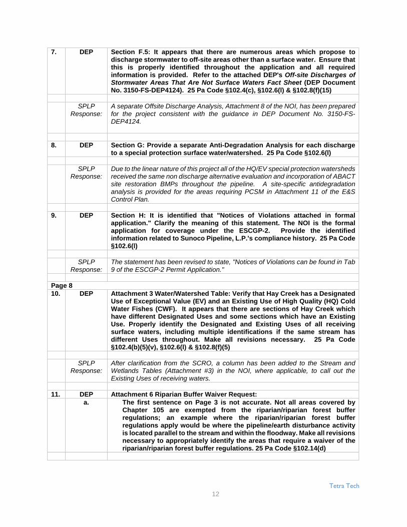
7. DEP Section F.5: It appears that there are numerous areas which propose todischarge stormwater to off-site areas other than a surface water. Ensure thatthis is properly identified throughout the application and all requiredinformation is provided. Refer to the attached DEP's Off-site Discharges ofStormwater Areas That Are Not Surface Waters Fact Sheet (DEP DocumentNo. 3150-FS-DEP4124). 25 Pa Code §102.4(c), §102.6(l) & §102.8(f)(15)
SPLPResponse:
A separate Offsite Discharge Analysis, Attachment 8 of the NOI, has been preparedfor the project consistent with the guidance in DEP Document No. 3150-FS-DEP4124.
8. DEP Section G: Provide a separate Anti-Degradation Analysis for each dischargeto a special protection surface water/watershed. 25 Pa Code §102.6(l)
SPLPResponse:
Due to the linear nature of this project all of the HQ/EV special protection watershedsreceived the same non discharge alternative evaluation and incorporation of ABACTsite restoration BMPs throughout the pipeline. A site-specific antidegradationanalysis is provided for the areas requiring PCSM in Attachment 11 of the E&SControl Plan.
9. DEP Section H: It is identified that "Notices of Violations attached in formalapplication." Clarify the meaning of this statement. The NOI is the formalapplication for coverage under the ESCGP-2. Provide the identifiedinformation related to Sunoco Pipeline, L.P.'s compliance history. 25 Pa Code§102.6(l)
SPLPResponse:
The statement has been revised to state, "Notices of Violations can be found in Tab9 of the ESCGP-2 Permit Application."
Page 810. DEP Attachment 3 Water/Watershed Table: Verify that Hay Creek has a Designated
Use of Exceptional Value (EV) and an Existing Use of High Quality (HQ) ColdWater Fishes (CWF). It appears that there are sections of Hay Creek whichhave different Designated Uses and some sections which have an ExistingUse. Properly identify the Designated and Existing Uses of all receivingsurface waters, including multiple identifications if the same stream hasdifferent Uses throughout. Make all revisions necessary. 25 Pa Code§102.4(b)(5)(v), §102.6(l) & §102.8(f)(5)
SPLPResponse:
After clarification from the SCRO, a column has been added to the Stream andWetlands Tables (Attachment #3) in the NOI, where applicable, to call out theExisting Uses of receiving waters.
11. DEP Attachment 6 Riparian Buffer Waiver Request:a. The first sentence on Page 3 is not accurate. Not all areas covered by
Chapter 105 are exempted from the riparian/riparian forest bufferregulations; an example where the riparian/riparian forest bufferregulations apply would be where the pipeline/earth disturbance activityis located parallel to the stream and within the floodway. Make all revisionsnecessary to appropriately identify the areas that require a waiver of theriparian/riparian forest buffer regulations. 25 Pa Code §102.14(d)

Tetra Tech
13
SPLPResponse:
The sentence has been revised to reflect that the riparian/riparian forest bufferregulations apply where the pipeline/earth disturbance activity is located parallel tothe stream and within the floodway.
b. If a waiver is being requested for a riparian forest buffer, then provide awaiver of the riparian forest buffer composition. Identify all areas for awaiver of the riparian forest buffer composition. 25 Pa Code §102.14(b)(1)
SPLPResponse:
Language has been added to the narrative clarifying that all forested riparian buffersare assumed to be of "composition," native with 60% canopy cover.
c. The provided Alternatives Analysis is not sufficient. Provide anAlternative Analysis for each area where the riparian/riparian forest bufferwaiver is being requested. 25 Pa Code §102.14(d)(2) & §102.14(d)(3)
SPLPResponse:
The Alternatives Analysis was expanded to incorporate each riparian zone. Thisexpanded analysis is included as Table 3 in the Riparian Buffer Waiver Request(Attachment 6 of the NOI - Tab 2).
d. Identify the specific manual which is referred to as "PADEP manual" onPage 11 in the Demonstration of Minimizing Impacts section. 25 Pa Code§102.14(d)(2) & §102.14(d)(3)
SPLPResponse:
The text has been revised to reference the "2012 PADEP Erosion and SedimentPollution Control Program Manual."
e. Table 2 identifies streams which are currently identified as impaired in the2014 Pennsylvania Integrated Water Quality Monitoring and AssessmentReport. Please note that some streams are currently tentatively impairedand may be identified as impaired in the 2016 Pennsylvania IntegratedWater Quality Monitoring and Assessment Report. If 2016 PennsylvaniaIntegrated Water Quality Monitoring and Assessment Report is finalizedbefore permit coverage is authorized for the project, then revise theapplication accordingly. 25 Pa Code §102.14(a)(2)
SPLPResponse:
This item has been noted. The comment period for the 2016 PennsylvaniaIntegrated Water Quality Monitoring and Assessment Report closed on September13, 2016, but DEP has not announced a date for the release of the final version ofthat report.
Page 9f. The Riparian Buffer Site Plans are not sufficient. Clearly identify
riparian/riparian forest buffer areas to be waived on the plans and identifythe top of bank of the stream. Provide these plans at a more legible scale;a scale of 1" = 400' is not sufficient for the riparian/riparian forest bufferwaivers. 25 Pa Code §102.14(d)(2) & §102.14(d)(3)
SPLPResponse:
The Riparian Buffer Site Plans have been updated to clearly identify allriparian/riparian forest areas and the top of bank of the streams. The plans havealso been updated to a scale of 1" = 100'.

Tetra Tech
14
PNDI Coordination/Clearance1. DEP Identify where on the plans the avoidance and clearance measures are
identified for the threatened and endangered species. Provide the avoidanceand clearance measures clearly shown and identified on all applicable plans,including notes and locations. 25 Pa Code §102.4(b)(5)(ix), §102.6(a)(2) &§102.8(f)(9)
SPLPResponse:
A "Rare, Threatened, and Endangered Species Restrictions and AvoidanceMeasures" table has been added to the plans and the drawings. Callouts have beenadded to the drawings at these locations to reference the required restrictions andavoidance measures.
2. DEP Provide clearance for all threatened and endangered species from all resourceagencies. 25 Pa Code §102.6(a)(2)
SPLPResponse:
Clearance letters for all threatened and endangered species from all resourceagencies are provided in Tab 6, Large Project PNDI.
Erosion & Sediment Control (E&S) Plan – General Technical Deficiencies1. DEP The E&S Plan shall be separate from the PCSM Plan. In certain instances the
E&S Plan and Site Restoration Plan can be combined; however, thiscombination has to be clearly identified. Make all revisions necessary. 25 PaCode §102.4(b)(5)(xiv), §102.8(d) & §102.8(n)
SPLPResponse:
The PCSM Plan has been updated to only include information regarding post-construction stormwater management BMPs and their installation, operation, andmaintenance. Also, the E&S Plan has been updated to only include informationregarding erosion and sediment control BMPs and their installation, operation, andmaintenance. The E&S Plan and PCSM Plan are now separate from one another.
2. DEP Provide the demonstration that the E&S Plan was prepared by a person trainedand experienced in E&S control methods and techniques applicable to the sizeand scope of the project being designed. DEP recommends utilizing StandardE&S Worksheet #22 from the E&S Manual. 25 Pa Code §102.4(b)(4) &§102.11(a)(1)
SPLPResponse:
Worksheet #22 has been completed and incorporated into Attachment 4 of the E&SReport.
3. DEP It appears that some of the symbols being used on the plan sheets are thesame or too similar to easily distinguish (e.g. LOD and 100 year floodplain, siltsock and silt fence, property line and right of way, etc.). Revise the plandrawings so that the line types are more distinguishable. 25 Pa Code§102.4(b)(5)(ix)
SPLPResponse:
The line types have been revised so they are easier to differentiate and are moredistinguishable.
4. DEP There are numerous instances where symbols are overlapping each other,making it hard to see some of the symbols. Revise the plan drawings so thatthe symbols are not overlapping. 25 Pa Code §102.4(b)(5)(ix)
Tetra Tech
15
SPLPResponse:
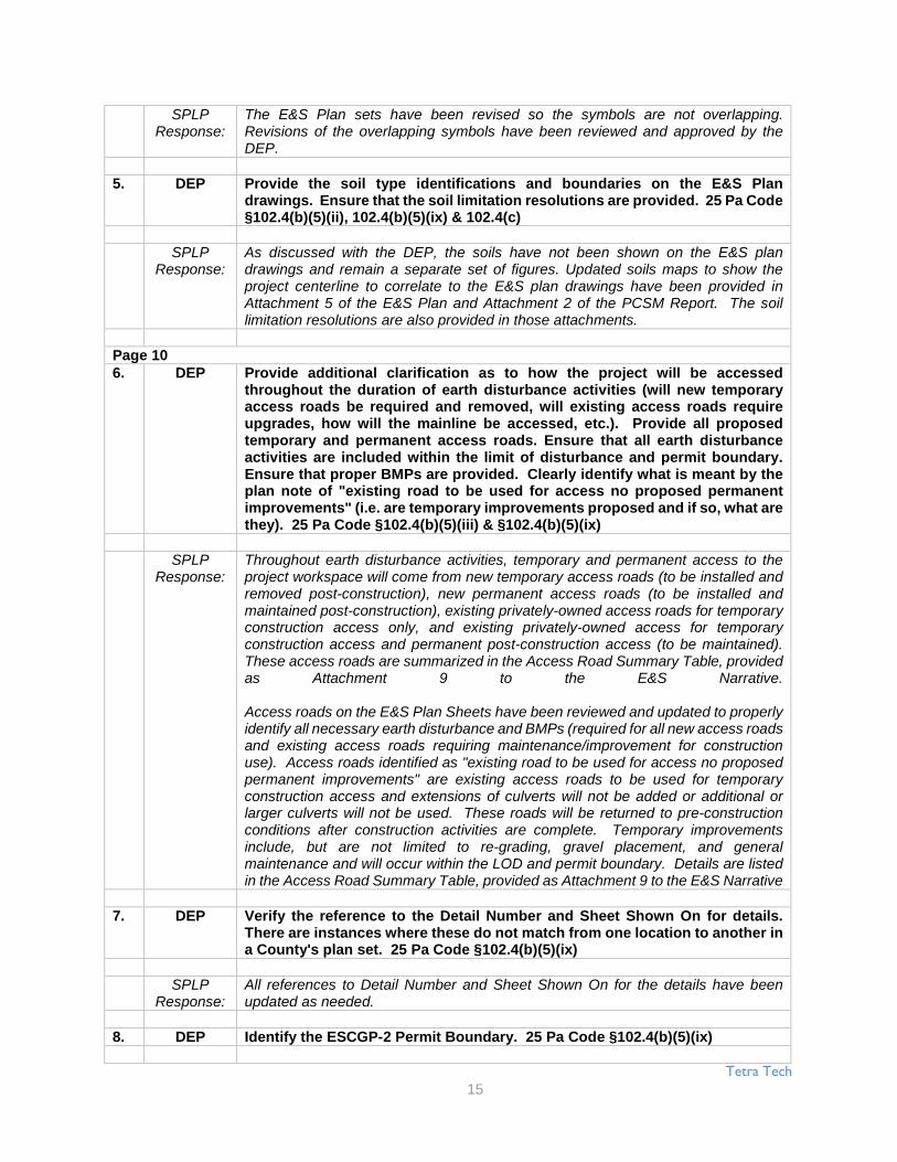
The E&S Plan sets have been revised so the symbols are not overlapping.Revisions of the overlapping symbols have been reviewed and approved by theDEP.
5. DEP Provide the soil type identifications and boundaries on the E&S Plandrawings. Ensure that the soil limitation resolutions are provided. 25 Pa Code§102.4(b)(5)(ii), 102.4(b)(5)(ix) & 102.4(c)
SPLPResponse:
As discussed with the DEP, the soils have not been shown on the E&S plandrawings and remain a separate set of figures. Updated soils maps to show theproject centerline to correlate to the E&S plan drawings have been provided inAttachment 5 of the E&S Plan and Attachment 2 of the PCSM Report. The soillimitation resolutions are also provided in those attachments.
Page 106. DEP Provide additional clarification as to how the project will be accessed
throughout the duration of earth disturbance activities (will new temporaryaccess roads be required and removed, will existing access roads requireupgrades, how will the mainline be accessed, etc.). Provide all proposedtemporary and permanent access roads. Ensure that all earth disturbanceactivities are included within the limit of disturbance and permit boundary.Ensure that proper BMPs are provided. Clearly identify what is meant by theplan note of "existing road to be used for access no proposed permanentimprovements" (i.e. are temporary improvements proposed and if so, what arethey). 25 Pa Code §102.4(b)(5)(iii) & §102.4(b)(5)(ix)
SPLPResponse:
Throughout earth disturbance activities, temporary and permanent access to theproject workspace will come from new temporary access roads (to be installed andremoved post-construction), new permanent access roads (to be installed andmaintained post-construction), existing privately-owned access roads for temporaryconstruction access only, and existing privately-owned access for temporaryconstruction access and permanent post-construction access (to be maintained).These access roads are summarized in the Access Road Summary Table, providedas Attachment 9 to the E&S Narrative.
Access roads on the E&S Plan Sheets have been reviewed and updated to properlyidentify all necessary earth disturbance and BMPs (required for all new access roadsand existing access roads requiring maintenance/improvement for constructionuse). Access roads identified as "existing road to be used for access no proposedpermanent improvements" are existing access roads to be used for temporaryconstruction access and extensions of culverts will not be added or additional orlarger culverts will not be used. These roads will be returned to pre-constructionconditions after construction activities are complete. Temporary improvementsinclude, but are not limited to re-grading, gravel placement, and generalmaintenance and will occur within the LOD and permit boundary. Details are listedin the Access Road Summary Table, provided as Attachment 9 to the E&S Narrative
7. DEP Verify the reference to the Detail Number and Sheet Shown On for details.There are instances where these do not match from one location to another ina County's plan set. 25 Pa Code §102.4(b)(5)(ix)
SPLPResponse:
All references to Detail Number and Sheet Shown On for the details have beenupdated as needed.
8. DEP Identify the ESCGP-2 Permit Boundary. 25 Pa Code §102.4(b)(5)(ix)

Tetra Tech
16
SPLPResponse:
The permit boundary is concurrent with the LOD on the E&S drawings.
9. DEP Ensure that all streams, floodways and floodplains have been fully identifiedin the plan drawings (e.g. Sheet ES-4.02 York County, S-H67). 25 Pa Code§102.4(b)(5)(v) & §102.4(b)(5)(ix)
SPLPResponse:
Floodplains and Floodways have been updated to match the plans included withSPLP’s Chapter 105 permit application.
10. DEP Ensure that adequate notes are provided related to the HDD sites. Refer toPages 284 & 285 of the E&S Manual for guidance on proper notes related tothe HDD and those work sites; identify where this information can be foundwithin the E&S Plan. 25 Pa Code §102.4(b)(5)(vi), §102.4(b)(5)(ix) &§102.11(a)(1)
SPLPResponse:
Additional notes have been added to the E&S Sheets related to the HDD sites. Thegeneral construction sequence for HDD crossings can be found under theConstruction Sequence notes on ES-0.05 or ES-0.06.
11. DEP There are numerous areas throughout the project where a wetland/portion ofa wetland is identified as within the limit of disturbance but that the E&S BMPsare not shown at the edge of the limit of disturbance (e.g. WL-BB111 at Station5764+50 on Sheet ES-3.01 for Blair County). Clarify the proposed disturbanceof these wetlands (i.e. are these wetlands to be disturbed or not). Provide adetail for the installation of the orange construction fence. 25 Pa Code§102.4(b)(5)(iii), §102.4(b)(5)(vi) & §102.4(b)(5)(ix)
SPLPResponse:
While crossing wetland areas the actual disturbance will be kept to a minimum;however, the limit of disturbance was kept at the outer edge of the right-of-way incase site conditions necessitated use of this area. In order to limit the actualdisturbance in the wetland, erosion and sediment controls are not shown on theedge of the right-of-way due to the need to disturb the wetland to place the controls.By not installing erosion controls at the edge of the right-of-way, the actualdisturbance in the wetland will be kept to a minimum.
Orange construction fencing (to limit entering the wetland) was added to the drawingset.
12. DEP For the stream and wetland crossings, provide specific site details as to howeach crossing will be accomplished. 25 Pa Code §102.4(b)(5)(iii),§102.4(b)(5)(vi), §102.4(b)(5)(vii) & §102.4(b)(5)(ix)
SPLPResponse:
The typical crossing details are relevant and applicable to each typical resourcecrossing, and will be implemented at each crossing without the need to specificallydepict such typical details on the plan views of the E&S Plan drawings. In severalcases, site-specific drawings have been created and are referenced within the E&SPlan sheets and provided after the standard sheeting. These sites-specifics alsoreference the typicals which provide a consistent location for the same information.
13. DEP The following technical deficiencies are associated with the constructionsequence: 25 Pa Code §102.4(b)(5)(vii)
a. Provide information for the clearing and grubbing, grading and pipelinetrench excavation.
Tetra Tech
17
SPLPResponse:
Based upon the regulatory citation, SPLP responds as follows: Number 6 of theConstruction Sequence has been revised to state, "Clearing, grubbing, and topsoilstripping shall be limited to those areas described in each stage of the constructionsequence. General site clearing, grubbing, and topsoil stripping may not commencein any stage or phase of the project until the E&S BMPs specified by the BMPsequence for that stage or phase have been installed and are functioning asdescribed in the E&S Plan."
Page 11b. Provide measures for how to relieve the compaction for the areas to be
restored (e.g. the pullback areas, access routes, pipeline backfill, etc.).
SPLPResponse:
Construction Sequence #16 was revised to state, "Any area that used stone and/ortimber mats for temporary stabilization and/or access will be completely removed,soil will be decompacted by using tracked equipment. Make multiple passes overthe area to reestablish preconstruction contours and replace topsoil to a minimumof 4-8 inches deep. Seed and mulch areas. Vehicular traffic should be restrictedfrom these areas to prevent soil compaction." Compaction is also addressed withinthe E&S narrative.
c. Provide for the restoration of the riparian forest buffer shown on the plandrawings.
SPLPResponse:
All riparian areas will be revegetated and stabilized following construction inaccordance with the Project’s E&S Plan, which incorporates antidegradationrequirements, and these areas will continue to provide riparian benefits to the streamresources.
d. Provide for the field marking of the wetlands.
SPLPResponse:
A note has been added to the construction sequence and general notes to state,"Orange construction fence will be installed at wetland areas to identify and deterconstruction equipment, vehicles, and personnel from entering wetlands."
e. Ensure that a construction sequence is provided for all block valve sites,permanent access roads and temporary access roads. In theseconstruction sequences provide for the installation/construction of thePCSM BMPs.
SPLPResponse:
A construction sequence for the installation and construction of PCSM BMPs isprovided on PCS-0.01 found in Attachment 6 of Tab 7 of the ESCGP-2 PermitApplication.
f. Provide for the maintenance of the waterbars during the periods of timewhere the pipe trench is open.
SPLPResponse:
Construction Sequence #9 has been revised to state, "Waterbars or approvedinterceptor dykes will be installed along the alignment prior to pipe installation at theend of each work day. During the periods of time where the pipe trench is open,contractors will provide positive control of all stormwater on site, water bars will beconstructed at the end, or during each work day. The contractor will install silt fenceif required to control erosion until 70% vegetation growth."

Tetra Tech
18
g. Stage 1 identifies that "Appropriately sized silt fence is an approvedalternative in areas that are not special protection watersheds." Identifyhow the proper sizing will be determined, as no sizing information wasprovided in the E&S Plan narrative and/or drawings. Provide the sizingcalculations and design, if silt fence is to be an approved alternative.Provide a note that identifies the appropriate county conservation districtand DEP have to approve any deviation to the authorized plans. 25 PaCode §102.4(b)(5)(viii)
SPLPResponse:
The design of the perimeter E&S Controls have been reevaluated for the maximumslope lengths and sock size adjusted accordingly to comply with the E&SPCPManual. Worksheet #1 has been updated to reflect this revision and can be foundin Attachment 4 of the E&S Report (Tab 3 of the ESCGP-2 Permit Application).
h. Identify the location of the Access Road Summary Table referenced inStage 3.
SPLPResponse:
The Access Road Summary Table is provided as Attachment 9 to the E&SNarrative.
i. Provide for the waterbars and approved interceptor dykes in Stage 5 to beinstalled at the end of each work day and not "as needed based oninstallation rate and weather conditions."
SPLPResponse:
A note has been added in Stage 5 of the Construction Sequence to state, "Waterbarsor approved interceptor dykes will be installed along the alignment prior to the pipeinstallation at the end of each work day. During the periods of time where the pipetrench is open, the contractor will provide positive control of all storm water on site.Waterbars will be constructed at the end of each work day, or during each work day.If required, the contractor will install silt fence to control erosion until 70% vegetativegrowth has been achieved."
j. Verify that the reference to the Sheet location for the compost filter socksizing and spacing chart is correct for all Counties in Stage 6.
SPLPResponse:
The reference sheet location for the compost filter sock sizing and spacing chart hasbeen checked and verified for all counties.
k. Stage 7 identifies to strip topsoil where required. Clearly identify whichareas will have the topsoil stripped and stockpiled separately (segregatedtopsoil).
SPLPResponse:
The Construction Sequence, #7, has been revised to state, "Strip topsoil from trencharea (where required) and stockpile within the right-of-way in accordance with thedetails provided. In wetlands, agricultural areas, and residential areas additionaltopsoil stripping and stockpiling might be required."
l. It appears that Stages 5 & 7 are out of sequence. Clarify this discrepancy.
SPLPResponse:
The sequencing has been reviewed and revised accordingly.
m. Stage 8 identifies to "minimize total area of disturbance"; clearly providehow the contractor is to minimize the total area of disturbance.

Tetra Tech
19
SPLPResponse:
Stage 10 (previously Stage 8) of the Construction Sequence, has been revised tostate: "Minimize total area of disturbance. Maintain temporary soil stockpiles withinexisting soil erosion and sediment controls. Should excavation enter streams, followspecific details for these areas shown on the drawings and include the steps detailedin the specific sections below. Pullback areas for HDDs will be cleared and preparedas needed to support staging, welding and testing of the HDD pipe sections. Areasnot utilized for construction activities should be avoided to minimize impacts."
n. Provide topsoil to be placed over all disturbed areas in Stage 9.
SPLPResponse:
Construction Sequence #13 (previously #9) has been revised to state, "Backfillexcavated area and cover with topsoil (where topsoil was segregated."
Page 12o. It appears that Stages 9 & 10 are out of sequence. Clarify this discrepancy.
SPLPResponse:
Construction Sequence #11 (previously #9 and #10), has been revised to state,"Install pipe and trench plugs in accordance with details on plan sheet ES-0.10.When open cutting driveways and access roads, contractor shall have road platesavailable to maintain access for landowners. The 20-inch pipeline will be installedfirst, followed by the 16-inch line. Any temporary stabilization required between thetwo installations will be implemented in accordance with this E&S Plan. Bothpipelines will be installed within the same limit of disturbance and in the sameconstruction period."
p. Verify that the reference to the Sheet location for the trench plug detail iscorrect for all Counties in Stage 10.
SPLPResponse:
Construction Sequence #11 (previously #10) has been reviewed and verified thatthe sheet locations for the trench plug details for all Counties are correct.
q. Verify that the reference to the Sheet location for the waterbar detail iscorrect for all Counties in Stage 11.
SPLPResponse:
Construction Sequence #9 (previously #11) reference to the sheet location for thewaterbar detail has been verified for all counties.
r. Revise Stage 14 to be "uniform 70% perennial vegetative cover".
SPLPResponse:
Construction Sequence #18 (formally Stage14) has been revised to state, "Maintainerosion and sedimentation control devices until site work is complete and a uniform70% perennial vegetative cover is established. Remove soil and erosion sedimentcontrol measures upon establishment of a uniform 70% perennial vegetativecoverage over the disturbed area. Re-grade and revegetate areas disturbed duringthe removal of the soil erosion and sediment controls."
Tetra Tech
20
14. DEP Revise Standard Erosion and Sediment Control Plan Note 26 such that upontemporary cessation of an earth disturbance activity or any stage or phase ofan activity where cessation of earth disturbance activities in non-specialprotection watersheds will exceed 4 days, the site shall be immediatelyseeded, mulched, or otherwise protected from accelerated erosion andsedimentation pending future earth disturbance activities and in specialprotection watersheds temporary stabilization shall be immediate. 25 Pa Code§102.4(b)(5)(vi), §102.4(b)(6) & §102.22(b)(1)
SPLPResponse:
Standard Erosion and Sediment Control Plan Note #27 (previously #26) has beenrevised to state, "Upon temporary cessation of an earth disturbance activity or anystage or phase of an activity where cessation of earth disturbance activities in non-special protection watersheds will exceed 4 days, the site shall be immediatelyseeded, mulched, or otherwise protected from accelerated erosion andsedimentation pending future earth disturbance activities and in special protectionwatersheds temporary stabilization shall be immediate."
15. DEP Clearly identify the length of time required to excavate the trench, install thepipe, backfill the trench and begin stabilization of the disturbed areas. Page283 of the E&S Manual identifies this length of time as not to exceed 30calendar days for most installations, and that long time periods may beapproved on a case-by-case basis. Clearly identify any areas that may exceed30 calendar days and provide sufficient justification for the extended timeperiod. 25 Pa Code §102.4(b)(5)(vi), §102.4(b)(6), §102.11(a)(1) & §102.11(b)
SPLPResponse:
Construction Sequence #12 has been revised to state, "The length of time requiredto excavate the trench, install pipe, backfill the trench, and begin stabilization ofdisturbed areas will not exceed 30 calendar days for most installations. Longer timeperiods may be approved by PADEP on a case-by-case basis."
16. DEP Revise Standard Erosion and Sediment Control Plan Note 25 to identify slopesof 3:1 or greater and all areas, regardless of slope, within 100 ft. of a specialprotection surface water to be blanketed with erosion control matting (per therecommendations on Page 273 of the E&S Manual). Ensure consistencybetween Standard Erosion and Sediment Control Plan Note 25 & 35 andConstruction Sequence Stage 12. 25 Pa Code §102.4(b)(5)(vi), §102.4(b)(6) &§102.11(a)(1)
SPLPResponse:
Standard Erosion and Sediment Control Plan Note #26 (previously #25) has beenrevised to state, "All graded areas shall be permanently stabilized immediately uponreaching finished grade. Cut slopes in competent bedrock and rock fills need notbe vegetated. Seeded areas within 100 feet of a special protection surface water,or as otherwise shown on the plan drawings, shall be blanketed according to thestandards of this plan." Note #36 of the Standard Erosion and Sediment ControlNotes and #15 of the Construction Sequence was also revised to state, "Erosioncontrol blanketing shall be installed on all slopes 3H:1V or greater and all areas,regardless of slope within 100 feet of a special protection surface water, and on allother disturbed areas specified on the plan maps and/or detail sheets."
17. DEP Identify if pumped water filter bags will be used during boring activities. If so,provide the location of the bags on the plan sheets. 25 Pa Code§102.4(b)(5)(vi) & §102.4(b)(5)(ix)
SPLPResponse:
The use of pumped water filter bags can be found on the HDD boring detail locatedon E&S Sheet ES-0.08 to be utilized if necessary during boring activities

Tetra Tech
21
18. DEP Pumped water filter bags alone are not rated as an antidegradation bestavailable combination of technologies (ABACT) BMP. Surrounding the pumpwater filter bag with a compost sock ring or by using the pumped water filterbag in conjunction with a sumped pit will elevate the pump water filter bag toan ABACT rating (per Page 53 of the E&S Manual). Clearly identify on the plandrawings or clearly in the detail (ensuring that proper additional details areprovided) the measures to ensure that pumped water filter bags for dischargesto special protection surface waters will achieve an ABACT rating. 25 Pa Code§102.4(b)(5)(vi), §102.4(b)(5)(ix), §102.4(b)(6) & §102.11(a)(1)
SPLPResponse:
In HQ or EV waters, CFS will be placed around the downslope side of the pumpedwater filter bags. This is noted in the third paragraph of the Pumped Water FilterBag Detail. Pumped Water Filter Bags will be used as needed along the Projectsite; therefore, the use of Pumped Water Filter bags has not been shown on the plandrawings because the locations of the Pumped Water Filter bags are not known atthis time.
Page 1319. DEP Ensure that all county references are correct (e.g. Notes for Site Restoration
Note 2 on Sheet ES-0.02 for Lebanon County references Lancaster County,Sheet ES-0.06 for Lebanon County references Washington County Limit ofDisturbance, etc.). 25 Pa Code §102.4(b)(5)(ix)
SPLPResponse:
The drawings have been reviewed to ensure all county references are correct.Sheets ES-0.02 and 0.06 have been updated to correspond to the correct county.
20. DEP Provide the waterbars on the plan drawings at the stream and wetlandcrossings, as identified in the Timber Mat Crossing Detail. 25 Pa Code§102.4(b)(5)(iii) & §102.4(b)(5)(ix)
SPLPResponse:
Water bars are placed a minimum of 50' from the top of bank per the detail and theDEP-designated floodway for streams that do not have a FEMA-designatedfloodplain. Water bars are placed where applicable outside that 50' buffer based ontopography. Areas where contours are parallel to the LOD cannot accommodatewater bars.
21. DEP The waterbars shown on the Timber Mat Crossing Detail are not shown on theplan view and are not identified to discharge to sediment control BMPs.Clarify these discrepancies. 25 Pa Code §102.4(b)(5)(vi) & §102.4(b)(5)(ix)
SPLPResponse:
Water bars are placed a minimum of 50' from the top of bank per the detail and theDEP-designated floodway for streams that do not have a FEMA-designatedfloodplain. Water bars are placed where applicable outside that 50' buffer based ontopography. Areas where contours are parallel to the LOD cannot accommodatewater bars. Compost Filter Socks (CFS) are applied at the end of each water bar,and along the edges of the ROW parallel to pre-disturbed surface gradients. Per theDEP BMP manual, edges of CFS are turned “upflow” at each location The waterbardetail has been modified to indicate the addition of the compost filter socks at theend of waterbars.

Tetra Tech
22
22. DEP Provide a detail for the J-hooks at the end of a waterbar. Provide thedemonstration that the designed J-hooks will function adequately andappropriately to manage the erosion and sedimentation from the runoff. 25Pa Code §102.4(b)(5)(iii), §102.4(b)(5)(viii), §102.4(b)(5)(ix) & §102.4(c)
SPLPResponse:
The compost filter sock (J-hooks) are shown on the individual E&S sheets andtypical detail #3 on ES-0.08. The J-hook will be upsized one standard size fromwhat the slope and up slope length would require from Worksheet 1 in the E&SDesign Calculations.
23. DEP Identify/distinguish which waterbars are temporary versus permanent on theplan drawing. 25 Pa Code §102.4(b)(5)(iii) & §102.4(b)(5)(ix)
SPLPResponse:
The water bars have been color coded to identify which are permanent versustemporary.
24. DEP Provide for surface roughening, as recommended on Page 260 of the E&SManual. If surface roughening is not proposed, then provide the alternativeBMP and design standard demonstration. 25 Pa Code §102.4(b)(5)(vi),§102.4(b)(5)(ix), §102.4(b)(6), §102.11(a)(1) & §102.11(b)
SPLPResponse:
Notes have been added to the E&S Plans to indicate that, "Surface rougheningshould be applied to slopes 3H:1V or steeper unless a stable rock face is providedor it can be shown that there is not a potential for sediment pollution to surfacewaters. For roughened surfaces within 50 feet of a surface water, and whereblanketing of seeded areas is proposed as the means to achieving permanentstabilization, spray-on type blankets are recommended. Surface roughening shallbe accomplished using dozers affixed with grouser tracked equipment. Dozers shallrun up and down the slopes leaving horizontal grooves perpendicular to the slope.Dozer blades shall be raised and not used during surface roughening."
25. DEP Identify the type of erosion control blanket/matting to be used and for whichconditions. Provide the staple pattern details for the erosion control blanketinstallations. 25 Pa Code §102.4(b)(5)(vi) & §102.4(b)(5)(ix)
SPLPResponse:
A table has been added to the E&S Plans on ES-0.07 to identify the types of erosioncontrol blanket and matting to be used for which conditions.
26. DEP Note 3 on the plan view drawings identifies that "BMP installation to beadjusted as needed..."; however, it is not clear who is to be determining theadjustment(s). Properly identify who will make the determination of adjustingthe BMPs. A deviation from the authorized plans may be necessary; however,the appropriate county conservation district and DEP have to approve anydeviation to the authorized plans. Make all revisions necessary to clearlyidentify this requirement. 25 Pa Code §102.4(b)(5)(vi) & §102.4(b)(5)(ix)
SPLPResponse:
The on-site Environmental Inspector and/or Inspection Chief will determine whetherany BMPs need to be adjusted. Language has been added to Note 3 on the planview drawings to identify that, "A deviation from the authorized plans may benecessary; however, the appropriate county conservation district and DEP mustapprove any material deviation to the authorized plans."

Tetra Tech
23
Page 1427. DEP Provide discussion related to the timing of the sequence of construction,
including how runoff will be properly managed from when the trench backfillis complete to the installation of the waterbars and permanent stabilization.25 Pa Code §102.4(b)(5)(iii), §102.4(b)(5)(vi) & §102.4(b)(5)(vii)
SPLPResponse:
The Construction Sequence, #9, has been revised to state, "Water bars or approvedinterceptor dykes will be installed along the alignment prior to pipe installation at theend of each work day. During the periods of time where pipe trench is opencontractors will provide positive control of all storm water on site, water bars will beconstructed at the end of each work day, or during each work day if requiredcontractor will install silt fence to control erosion until 70% vegetation growth hasbeen achieved."
28. DEP The Right-Of-Way Detail (e.g. Sheet ES-0.08 for Blair County) shows compostfilter sock running parallel with edge of the right-of-way; which is inconsistentwith the plan drawings. Provide a note with this detail that compost filter sockshould be installed parallel with existing contours and as shown on the plandrawings. 25 Pa Code §102.4(b)(5)(vi) & §102.4(b)(5)(ix)
SPLPResponse:
A note has been added to the right of way detail (now ES-0.11).
29. DEP Provide additional information in the Right-Of-Way Detail, which identifies theapprox. depth of existing topsoil and the amount of topsoil to be placed at thesurface during the trench backfill operations. 25 Pa Code §102.4(b)(5)(vi) &§102.4(b)(5)(ix)
SPLPResponse:
A note has been added to the right of way detail (now ES-0.11).
30. DEP The Bank Restoration Detail (e.g. Sheet ES-0.10 for Blair County) shows theuse of erosion control blanket and native plantings. Identify the type oferosion control blanket and the native plantings to be used. 25 Pa Code§102.4(b)(5)(vi) & §102.4(b)(5)(ix)
SPLPResponse:
The existing stream bank restoration detail has been revised to indicate that theexisting bank, slope, grade, and elevation will be restored with a biodegradableerosion control blanket and existing streambed material. Where a-typical streambanks are anticipated and at locations requested by PADEP, site specific restorationdetails have been added to the E&S plan drawings for those crossing locations.
31. DEP Provide a note on the E&S Plan that identifies no soil amendments (lime,fertilizer, etc.) are to be used in wetland areas (refer to Page 265 of the E&SManual). 25 Pa Code §102.4(b)(5)(vi), §102.4(b)(5)(ix) & §102.11(a)(1)
SPLPResponse:
A note has been added to the Standard Erosion and Sediment Control Plan Notes(ES-0.06) and to the notes regarding Working in a Wetland Area which states, "Nosoil amendments such as agricultural lime or fertilizer will be used within wetlandareas."

Tetra Tech
24
32. DEP Identify/label the compost filter socks in the plan view drawings, so that thesizing can be verified with Standard E&S Worksheet #11. On all plan viewdrawings, ensure that all sediment barriers (compost filter socks, silt fences,etc.) are shown with the ends turned upslope at 45 degrees to the main barrieralignment for a distance sufficient to elevate the bottom of the barrier ends tothe elevation of the top of the bather at the lowest point. 25 Pa Code§102.4(b)(5)(ix)
SPLPResponse:
33. DEP Spot checks at several locations found that a number of maximum slopelengths appear to have been exceeded for the proposed compost filter socks(e.g. Socks #7, 8, 24, 27, 29, 32, and 49 for Lancaster County). Ensure that thecompost filter socks are sized according to the maximum slope length abovethe sock, not just the disturbed area above the sock, as identified in the E&SManual. If the recommended maximum slope length from the E&S Manual isexceeded, then a demonstration of alternative BMP and design standard mustbe provided. 25 Pa Code §102.4(b)(5)(vi), §102.4(b)(5)(viii), §102.4(b)(5)(ix),§102.11(a)(1) & §102.11(b)
SPLPResponse:
The design of the compost filter socks has been reevaluated for the maximum slopelengths and sock size adjusted accordingly to comply with the manual. Worksheet#1 has been updated to reflect this revision. If compost filter sock was not adequate,a temporary diversion and slope pipe is proposed to divert clean water through theproject area.
Page 1534. DEP The compost standards identified in Table 4.2 in Attachment 4 of the E&S Plan
narrative are not correct. Per the Corrections For Erosion And SedimentPollution Control Program Manual TON 363-2134-008 Mach 2012, the followingare the correct compost standards:
Organic Matter Content: 25% - 100% (dry weight basis)Organic Portion: Fibrous and elongatepH: 5.5 - 8.5Moisture Content: 30% - 60%Particle Size: 30% - 50% pass through 3/8" sieveSoluble Salt Concentration: 5.0 dS/m (mmhos/cm) Maximum.
Make all revisions necessary. 25 Pa Code §102.4(b)(5)(vi), §102.4(b)(5)(ix) &§102.11(a)(1)
SPLPResponse:
The compost standards in Table 4.2 of Attachment 4 of the E&S Plan narrative havebeen updated to reflect the latest compost standards from the March 31, 2015modifications to the Erosion and Sediment Control Program Manual - March 2012.
35. DEP Provide Table 4.1 (from Page 63 of the E&S Manual) and the corrected Table4.2 (from the E&S Manual and Corrections for Erosion and Sediment PollutionControl Program Manual TGN 363-2134-008 Mach 2012) on the plan drawingsheet with the Compost Filter Sock detail. 25 Pa Code §102.4(b)(5)(vi) &§102.4(b)(5)(ix)
SPLPResponse:
Table 4.1 and the updated Table 4.2 have been added to the compost filter sockdetail.

Tetra Tech
25
36. DEP Provide each HDD location's staging areas, including contours (if grading isto be accomplished), stockpile locations (if necessary), etc. Provide ademonstration that perimeter controls are sufficient for these large areas andthat other E&S BMPs, such as sediment basins, sediment traps, etc., will notbe required to properly manage the runoff. 25 Pa Code §102.4(b)(5)(iii),§102.4(b)(5)(vi) & §102.4(b)(5)(ix)
SPLPResponse:
HDD staging areas are shown on the plan sheets. Where grading is necessary foruse of the staging area, grading is shown. All E&S BMPs have been verified.
37. DEP Provide discussion on what E&S BMPs will be utilized at the HDD andconventional boring locations for the drilling mud. Ensure that these BMPsare properly shown on the plan view drawings. 25 Pa Code §102.4(b)(5)(iii),§102.4(b)(5)(vi) & §102.4(b)(5)(ix)
SPLPResponse:
Drilling mud will be stored in tanks or pits at the HDD and conventional boringlocations and therefore the management of drilling mud is not expected to have anyimpact on erosion or sedimentation. E&S BMPs for stormwater are shown on theE&S plans.
38. DEP The Standard Construction Detail #13-4 in Attachment 4 of the E&S Plannarrative and the Trench Plug Installation detail (e.g. Sheet ES-0.10 for BlairCounty) are not correct. The Standard Construction Detail #13-4 from the E&SManual was revised per the Corrections for Erosion and Sediment PollutionControl Program Manual TGN 363-2134-008 Mach 2012, to identify the trenchplugs extending to the trench bottom (as opposed to the bottom of the pipe).If an alternative BMP and design standard will be used for trench plugs, thenthat demonstration shall be provided. 25 Pa Code §102.4(b)(5)(vi),§102.4(b)(5)(ix), §102.11(a)(1) & §102.11(b)
SPLPResponse:
An updated trench plug detail has been provided (now ES-0.11) to be consistentwith the correction sheet.
39. DEP Ensure the entire length of a surface water (and any adjacent features) isshown within the Permit Boundary. It appears that only sections of streamsare shown that start/stop in the middle of the right-of-way. If the streams areshown correctly, then provide a narrative discussion identifying thesefeatures. 25 Pa Code §102.4(b)(5)(v) & §102.4(b)(5)(ix)
SPLPResponse:
The wetland and stream delineations were based on 200-foot-wide surveycorridor. The delineation of these features and the extent of the survey area aredocumented within the wetland reports and supplementals provided with theChapter 105 and 102 applications. At times streams do start and/or end within thesurvey corridor and this represents the alignment of the stream as surveyed in thefield. The narratives are found within the wetland reports and supplementals. TheChapter 105 permit application comments requested that we field visit many of thesecases and verify the survey and take additional pictures. That additional fieldworkwas completed and the data gathered is provided within the supplementalreports included within this revised application.

Tetra Tech
26
Page 1640. DEP Provide discussion as to why HDD or conventional boring was not utilized to
cross all special protection surface waters, as boring could be considered anABACT E&S BMP (refer to Page 290 of the E&S Manual). It appears that boringcould be accomplished at Station 6900+00 (Sheet ES-3.67 for Blair County) forthe crossing of Clover Creek (HQ-CWF). 25 Pa Code §102.4(b)(5)(vi),§102.4(b)(6) & §102.11(a)(1)
SPLPResponse:
The alternatives analysis included within the Chapter 105 application has beenrevised to demonstrate that the proposed pipeline route has been designed tominimize the number and linear footage of crossings of all surface waters, includingthose classified as High Quality (HQ) or Exceptional Value (EV), and adopted theuse of trenchless crossing installation methods at selected surface water crossings,to the maximum extent practicable. For each surface water, including HQ and EVsurface waters, crossed by the open cut installation method, the E&S Plan identifiesand incorporates ABACT E&S best management practices (BMPs).
41. DEP Provide additional information related to the geotextile (e.g. type, strength,etc.) identified to be used under the timber mats in the Timber Mat Detail (e.g.Sheet ES-0.09 for Blair County) 25 Pa Code §102.4(b)(5)(vi) & §102.4(b)(5)(ix)
SPLPResponse:
The typical timber mat detail has been revised to include information on thegeotextile. The timber mat detail is located on E&S Sheet ES-0.18.
42. DEP It appears that the temporary seeding information is not consistent betweenthe narrative and the plan drawings. Clarify this discrepancy. 25 Pa Code§102.4(b)(5)(vi) & §102.4(b)(5)(ix)
SPLPResponse:
The temporary seeding information has been reviewed and verified to be consistentbetween the narrative and the plan drawings.
43. DEP The existing riparian forest buffers do not appear to be shown correctly. Forexample, the existing riparian forest buffer identified for Stream S-196 onSheet ES-3.03 for Blair County is shown to be approx. 100 ft. wide. Riparianforest buffers are 150 ft. in width. Identify the full riparian forest buffer. Makeall revisions necessary. 25 Pa Code §102.4(b)(5)(ix) & §102.4(b)(5)(xv)
SPLPResponse:
The classification of the UNT to Blair Run was identified as a CWF for which theriparian buffer is reflected at 100 feet on ES -3.03. Riparian forested buffers areshown at 100 feet for other waters and 150 feet for special protection. SPLP andPADEP agreed that buffers at non special protection waters are to be shown at 100feet and 150 feet at special protection waters.
44. DEP If any soil stockpiles are needed due to the installation of the rockconstruction entrances, then provide/identify those stockpiles on the planview drawings. Make all revisions necessary. 25 Pa Code §102.4(b)(5)(iii),§102.4(b)(5)(vi) & §102.4(b)(5)(ix)
SPLPResponse:
The protection of soil/spoil stock piles will be in accordance with the detail on ES 0-09. Stock piles will be located within the proposed limit of disturbance.

Tetra Tech
27
45. DEP Compost sock sediment traps are shown to be utilized (e.g. approx. Station7662+00 on Sheet ES-3.39 for Huntingdon County); however, the sizingcalculations could not be located in the E&S Plan narrative. Provide the sizingcalculations for all compost sock sediment traps. 25 Pa Code §102.4(b)(5)(viii)& §102.4(b)(5)(ix)
SPLPResponse:
The sizing calculations for E&S BMPs utilized throughout the length of the pipelineare located in Attachment 4 of the E&S Report (Tab 3 of the ESCGP-2 PermitApplication).
46. DEP Provide the proposed grading for all proposed features (including theinfiltration berms for the valve sites, stations, etc.). 25 Pa Code§102.4(b)(5)(iii) & §102.4(b)(5)(ix)
SPLPResponse:
All grading for proposed features is provided on the E&S and PCSM plan drawings.
47. DEP The following technical deficiencies are related to the restoration activitiesduring the earth disturbance activities:
a. Provide more identification in the narratives and on the plan drawingsrelated to topsoil segregation. 25 Pa Code §102.4(b)(5)(iii), §102.4(b)(5)(vi)& §102.4(b)(5)(ix)
SPLPResponse:
The Construction Sequence, #8 (previously #7), has been revised to state,"Clearing, grubbing, and topsoil stripping shall commence along the pipeline routeand be limited to those areas described in each stage of the construction sequence.General site clearing, grubbing and topsoil stripping may not commence in any stageor phase of the project until the E&S BMPs specified by the BMP sequence for thatstage or phase have been installed and are functioning as described in this E&Splan. For clearing, grubbing, and topsoil removal in all stream, river, wetland or otherwater body crossings, refer to construction sequence notes below. Topsoil will besegregated at locations throughout the project where topsoil exists." The details areshown on the Details on sheet ES-0.09, 0.11-0.17 of the plans
b. Provide more identification in the narratives and on the plan drawingsrelated to loosening of compacted soils prior to topsoil placement andstabilization (at the temporary access roads, topsoil stockpiles, accessroutes along the mainline, etc.). 25 Pa Code §102.4(b)(5)(iii),§102.4(b)(5)(vi) & §102.4(b)(5)(ix)
SPLPResponse:
Construction Sequence #16 was revised to state, "Any area that used stone and/ortimber mats for temporary stabilization and/or access will be completely removed,soil will be decompacted by using tracked equipment. Make multiple passes overthe area to reestablish preconstruction contours, and replace topsoil to a minimumof 4-8 inches deep. Seed and mulch areas. Vehicular traffic should be restrictedfrom these areas to prevent soil compaction."

Tetra Tech
28
Page 17c. Provide a discussion of measures that will be taken to avoid and minimize
compaction to the maximum extent practicable and where compactionoccurs, what measures will be taken to ensure adequate infiltration andsuccessful vegetation of the right of way. 25 Pa Code §102.4(b)(4) &§102.22
SPLPResponse:
Compaction concerns are restricted to the limit of disturbance, which has beenminimized to the maximum extent practicable. Within the pipeline right of way, travellanes will be utilized to restrict the extent of compaction. Following installation of thepipeline, deep ripping or chisel plowing will occur to alleviate compaction, promoteinfiltration, and facilitate vegetative growth. The site restoration constructionsequence has been updated in the Site Restoration and Post-ConstructionStormwater Management Plan narrative and on drawing PCS-0.01. The sequencenow specifies chisel plowing or incorporating soil amendments where compactionoccurs. The sequence also specifically addresses restoration of access roads.
d. Describe how your planning and design requirements satisfy 25 Pa Code§102.4(b)(4) and are minimizing the extent and duration of theconstruction and the minimizing any increase in stormwater runoffIdentify how these measures are satisfied when the ROW is in closeproximity or is crossings surface waters or wetlands.
SPLPResponse:
The Site Restoration and Post Construction Stormwater Management Planaddresses how the project minimizes the extent and duration of construction tominimize stormwater. The plan addresses the potential impacts to surface waterswhen the corridor is in close proximity or crosses the surface waters and how thewaters are protected.
48. DEP Clarify if the dual pipelines will be constructed within the same trench or if twotrenches will excavated. If the dual pipelines will be installed within the sametrench, then provide the trench plugs for each pipeline at the samelocation/Station (not at different locations/Stations; e.g. Station 13289+50 onSheet ES-1.05 for Berks County and Station 13314+50 on Sheet ES-1.06 forBerks County). Make all revisions necessary. 25 Pa Code §102.4(b)(5)(vi) &§102.4(b)(5)(ix)
SPLPResponse:
The Project Description throughout the Application has been updated to reflect thetiming of the installation of the 20-inch and the 16-inch pipeline. In general, the 20-inch pipeline would be installed first, followed by the 16-inch line. For a conventionallay, the pipelines would be installed within the same disturbance to the maximumextent practicable. For safety purposes, the installation would be staggered by whatis estimated to be no more than 60 days. At some HDDs with longer drills, however,the time period between installations of the two pipelines may exceed 60 days. Anytemporary stabilization required would be implemented in accordance with theProject’s E&S Plans.
The E&S Plans have been reviewed and revised to display the trench plugs for eachof the two pipelines at the same locations.

Tetra Tech
29
49. DEP Ensure that all earth disturbances are properly identified and included withinthe limit of disturbance and the Permit Boundary. Describe theinstallation/construction for the test water source piping, the construction ofthe test water source pump pad, installation of culvert to cross railroad tracks,etc. (e.g. Sheets ES-4.03 & 4.04 for Dauphin County). If earth disturbance isproposed, then provide the appropriate E&S BMPs and all necessary planinformation. 25 Pa Code §102.4(b)(5)(iii), §102.4(b)(5)(vi), §102.4(b)(5)(vii),§102.4(b)(5)(ix) & §102.4(b)(5)(x)
SPLPResponse:
As stated in Note 3 on ES 4.03, all surface water withdrawal equipment will betemporary and above-ground. Additionally, the pump will be located on an existinggravel parking lot on Highspire Boating Association property; therefore, a pad willnot need to be installed. The water intake hose and screen will be removed fromthe floodway when not in use. No dredging or filling activities will be completedwithin the Susquehanna River as part of the water withdrawal activities. Thetemporary piping through the existing culvert under the Amtrak railroad tracks willbe installed in a manner whereby it is easily removed when not in use or prior to anyflooding events. A hydraulic analysis of the culvert was completed thatdemonstrated that the culvert is adequately sized to accommodate the temporaryhose as well as normal Burd Run flow rates. See E&S Report Attachment 8 for thesupporting calculations. Drawing ES 4.03 has been revised to include limits ofdisturbance to encompass water withdrawal activities and the access roads.
50. DEP Provide specific E&S BMPs for each stream and wetland crossing. It isrecommended that a blow-up of each specific stream and wetland crossing beprovided, which clearly illustrates all E&S BMPs. 25 Pa Code §102.4(b)(5)(iii),§102.4(b)(5)(vi) & §102.4(b)(5)(ix)
SPLPResponse:
Site specific details with appropriate E&S BMPs have been included for stream andwetland crossings. The details can be found at the end of each County E&S Planset in Attachment 2 of the E&S Report (Tab 3 of the ESCGP-2 permit application).
51. DEP If trench plugs will be utilized at the boring locations, then the trench plugsshall be shown on Bore Crossing in the Typical Stream Crossing detail (e.g.Sheet ES-0.09 for Blair County). Provide a typical wetland crossing detail,which is similar to the Typical Stream Crossing detail (e.g. Sheet ER-0.09 forBlair County). 25 Pa Code §102.4(b)(5)(vi) & §102.4(b)(5)(ix)
SPLPResponse:
Boring does not unconsolidate soil; therefore, water will not travel along this pathand stream/wetland integrity will remain intact. Trench plugs for borings have notbeen added to the Typical Stream Crossing detail. Also, a typical wetland crossingdetail is provided on ES-0.15.
52. DEP Ensure that all ATWS locations are properly identified and that the E&S Planincludes the duration of proposed activities, the expected layout, E&S BMPs,and size or quantity of materials or structures proposed. 25 Pa. Code§102.4(b)(5)(ix)
SPLPResponse:
All ATWS locations are identified. Where specific activities are known, they arecalled out on the E&S Plan Sheet. Other areas are available for contractor use. AllE&S BMPs were verified and are shown on the plans. Should the ATWS require achange in BMPs during construction, standard permit modification procedures willbe followed.

Tetra Tech
30
Page 1853. DEP The site plan sheets from the Chapter 105 permit applications and E&S Plan
sheets identify the floodway which appear to be measured from the centerlineof the stream as opposed to the top of bank for the 50-feet assumed floodwayboundary. Provide floodway boundaries on all plan drawings that adhere tothe definitions in Chapter 105 by providing the FEMA mapped floodwayboundary, in areas absent a FEMA mapped floodway, the floodway boundarymeasured 50 feet landward from the top of bank, or in areas absent a FEMAmapped floodway a floodway boundary with evidence provided that theassumed 50 feet floodway is not accurate. 25 Pa. Code §102.4(b)(5)(ix) &§105.1
SPLPResponse:
Floodplains and Floodways have been updated to match the plans included with theChapter 105 permit application, 50' from top of bank, where FEMA floodplains andfloodways are not delineated.
54. DEP The Typical Wetland Crossing detail on the E&S Plan indicates soil will bestockpiled in the wetland along the trench. Revise the detail to include ameans of separating the stockpiled soil from the wetlands, such as geo-fabricand matting, to ensure full removal of the stockpiled soil and minimizeimpacts. 25 Pa. Code §102.4(b)(5)(vi) & §102.4(b)(5)(ix)
SPLPResponse:
The topsoil will be removed by pushing it to one side of the construction boundary.This will cause the topsoil to sit on topsoil, in the wetland, which is standard practice.Wetland topsoils and subsoils are kept within the wetland boundaries to maintainsoil properties to the greatest extent practical. Only wetland soils are stockpiled inthese boundaries. All upland soil stockpiles are kept a minimum of 10-feet from thewetland. This segregation practice makes wetland restoration easier and moreeffective than moving the soils a distance out of the wetlands. The detail for wetlandstockpiles notes that a physical separation is to be provided.
55. DEP The typical wetland crossing details shown on the E&S Plans indicates TrenchBreakers are to be installed in the trench in the wetlands; however it is notclear what Trench Breakers are or if Trench Plugs are what is meant. Revisethis detail to identify if Trench Plugs are meant by this term or provide a detailfor trench breakers. In addition, if trench plugs are proposed to maintainwetland hydrology, revise the detail to include trench plugs within the wetlandfor long wetland crossings and specify the distance increments. Furthermore,the E&S Plan drawings depict trench plugs which are inconsistent with thedetail. Revise the site plans to be consistent with the detail. 25 Pa. Code§102.4(b)(5)(vi) & §102.4(b)(5)(ix)
SPLPResponse:
Trench plugs are proposed at the trench extents within the limits of the wetlandboundary. The detail indicates the installation and location of the trench plugs atwetland crossings in order to maintain wetland hydrology. Locations of the trenchplugs are indicated on the typical wetland crossing detail, E&S plans, and sitespecific plan drawings.
56. DEP The Typical Wetland Crossing detail on the E&S Plan states that the detaildoes not apply to active cultivated or rotated cropland. Revise the detail toapply to all wetland crossings or provide a separate detail for wetlandcrossings in active cropland. 25 Pa. Code §102.4(b)(5)(vi) & §102.4(b)(5)(ix)

Tetra Tech
31
SPLPResponse:
A new typical wetland crossing detail has been created (ES-0.15) which now appliesto all wetland crossings.
57. DEP The Mitigation Plan (from the Chapter 105 permit application) states that theexcavated stream banks will be reseeded; however, the E&S Plan's detail forbank restoration does not indicate this. Revise the Bank Restoration Detail tobe consistent and include the native seeding mixture to be utilized. 25 Pa.Code §102.4(b)(5)(vi) & §102.4(b)(5)(ix)
SPLPResponse:
The bank restoration details, both site specific and typical, have been revised toindicate that the stream banks will be reseeded in accordance with the seed mix forwaterways on the E&S plan drawings.
58. DEP The E&S Plan details for temporary stream crossings and plan drawings statetimber mats or temporary equipment bridge may be utilized but only depictsa timber mat bridge. Provide details for the proposed temporary equipmentbridge(s) which depict the size, shape, and span of the structure. Provideseparate details depicting the timber mat and other bridge structurecrossing's cross sections. In addition, revise the E&S Plan and/or other plandrawings to identify the method of each temporary stream crossing proposedat each location. 25 Pa. Code §102.4(b)(5)(vi) & §102.4(b)(5)(ix)
SPLPResponse:
Details for a temporary timber mat and a temporary timber bridge have been addedto E&S Sheet ES-0.11, which includes the size, shape, and span of the structure.Site specific crossings have been added to the E&S Plans and can be found inAttachment 2 of the E&S Report (Tab 3 of the ESCGP-2 permit application). TheE&S Plans have been revised to identify the appropriate temporary stream crossingmethod proposed at each location.
Page 1959. DEP Revise the E&S Plan to include all avoidance and minimization measures for
identified species of concern associated with water obstructions andencroachments from the Pennsylvania Game Commission, Pennsylvania Fishand Boat Commission, Pennsylvania Department of Conservation and NaturalResources, and the U.S. Fish and Wildlife Service. Ensure any seed mixtures,matting, or other specified items are included in the plans and/or E&S plans.In addition, revise the Environmental Assessment to discuss the avoidanceand minimization measures and clearances received. 25 Pa. Code §102.6(a)(2)& §102.4(b)(5)(ix)
SPLPResponse:
A "Rare, Threatened, and Endangered Species Restrictions and AvoidanceMeasures" table and a "Seasonal In Stream Restrictions" table have been added tothe plans and the drawings. The Environmental Assessment is being updated in theChapter 105 permit.
60. DEP Section 2.2.2.1 of the Mitigation Plan (from the Chapter 105 permit application)identifies that wetlands will be reseeded with a native wetland seed mixture;however, the mixture is not specified nor is it proposed on the plans. Revisethe application to identify the seed mixture to be used and revise the E&SPlans to indicate its use for wetland restoration in the Typical WetlandRestoration detail. 25 Pa. Code §102.4(b)(5)(vi) & §102.4(b)(5)(ix)
SPLPResponse:
The wetland seed mixture identified in the Chapter 105 Mitigation Plan has beenadded to the E&S Plans with the other seed mixtures for the project on ES-0.05.

Tetra Tech
32
61. DEP Trench plugs are proposed to be located at wetland/upland interfaces.Additional trench plugs may be necessary along the length of the crossingdue to the length and/or slope to maintain hydrology throughout the wetland.Review and revise the application and plans accordingly. 25 Pa. Code§102.4(b)(5)(vi) & §102.4(b)(5)(ix)
SPLPResponse:
The trench plug locations relative to the wetlands have been reviewed and revisedas necessary throughout the drawings sets.
62. DEP Temporary road stream crossing details utilizing culverts are provided on E&SPlans ES-0.09 and ES-0.11 (e.g. from Blair County); however, the E&S Plansand impact plans (from the Chapter 105 permit application) do not identify thatany of these crossings are to be used. Revise the E&S Plans to remove theseproposed crossing methods if not proposed to be utilized, or identify wherethe proposed crossing methods will be utilized. 25 Pa. Code §102.4(b)(5)(vi)& §102.4(b)(5)(ix)
SPLPResponse:
The E&S Plan provides the contractor the option to use DEP approved standardtypical details for temporary road crossings. The approved details will be used incases where alternative crossing methods are needed by the contractor to facilitatethe crossing and safe installation of the pipelines.
E&S Plan – Berks County Technical Deficiencies1. BCCD Exceptional Value (EV) wetlands include wetlands that are located in or along
the floodplain of a reach of a wild trout stream or waters listed as exceptionalvalue under Chapter 93 (relating to water quality) and the floodplain of streamstributary thereto. It appears that the following wetlands are EV: Wetlands WL-B22, B24, B26, B27, B29, B33, B34, B38, B41, B42, B43, B44, B45, B46, B49,C1, C3, C5, C6, C7, C8, C12, C13, C14, BB133, W48, AM2, H14, H18, H19 H21,H22, 301 & Q80. Clearly identify the receiving surface waters, including EVwetlands. Provide an antidegradation analysis for all discharges to specialprotection surface waters, including the use of ABACT BMPs. Make allrevisions necessary. 25 Pa Code §102.4(b)(5)(v), §102.4(b)(5)(ix), §102.4(b) &§105.17(l)(iii)
SPLPResponse:
An antidegradation analysis for the EV wetlands noted in Berks County is providedin Section 3.6. An antidegradation analysis has been provided for all discharges tospecial protection surface waters in Section 3.6 of the E&S narrative.
2. BCCD Revise Note 2 on Sheet ES-0.02 to properly identify that this portion of theproject takes place in Berks County, not Lancaster County. 25 Pa Code§102.4(b)(5)(ix)
SPLPResponse:
Note 2 on Sheet ES-0.02 has been revised to properly identify that this portion ofthe project takes place in Berks County.

Tetra Tech
33
Page 203. BCCD Compost filter socks shown on Sheet ES-1.15 along the proposed access
drive for the Montello Block Valve Station are not shown parallel to existingcontour. As with other sediment barriers, compost filter socks should beplaced parallel to contour with both ends of the sock extended upslope at a45 degree angle to the rest of the sock to prevent end-around flows (refer toPage 62 of the E&S Manual). Make all revisions necessary. 25 Pa Code§102.4(b)(5)(ix) & §102.11(a)(1)
SPLPResponse:
Compost filter socks have been specified to capture stormwater coming downslopefrom the elevated rails, paralleling the access road to the southeast. In this case,the CFS are correctly shown parallel to the elevated rail bed contours, and willprevent runoff carrying sediment out of the LOD to the northwest.
4. BCCD It appears that the fill slopes at the Montello Block Valve Site (along accessdrive; Sheet ES-1.15)) and cut and fill slopes at the Wyomissing Block ValveSite (around pad area; Sheet ES-1.35) are steeper than 3:1. Clarify why theseareas are not shown to receive erosion control blanketing (as other areas onthe plan drawings clearly identify where erosion control blanketing isrequired). Show the extent of all erosion control blanketing on the plandrawings. 25 Pa Code §102.4(b)(5)(ix)
SPLPResponse:
The access road and block valve pad fill slopes have been revised to include erosioncontrol blanketing.
5. BCCD ATWS on Sheet 1 of Tab 7A in the floodplain and floodway of Stream S-B16(from the Chapter 105 permit application) is designated for spoil; however, aplan depicting the location of the spoil in conjunction with E&S controls couldnot be found. Ensure that the E&S Plan demonstrates proper measures tominimize the potential for discharge of fill material to the stream. 25 Pa. Code§102.4(b)(5)(vi) & §102.4(b)(5)(ix)
SPLPResponse:
E&S Sheet ES-1.01 has been revised to identify the location of spoil stockpiles andto include associated E&S Controls to minimize the potential for discharge of fillmaterial to the stream. A soil stockpile typical detail has also been added to the E&SPlan.
6. BCCD ATWS on Sheet 31 of Tab 7A in the floodway of Stream S-H21 (from theChapter 105 permit application) is designated for spoil; however, a plandepicting the location of the spoil in conjunction with E&S controls could notbe found. Ensure that the E&S Plan demonstrates proper measures tominimize the potential for discharge of fill material to the stream. 25 Pa. Code§102.4(b)(5)(vi) & §102.4(b)(5)(ix)
SPLPResponse:
E&S Sheet ES-1.54 has been revised to identify the location of spoil stockpiles andto include associated E&S Controls to minimize the potential for discharge of fillmaterial to the stream. A soil stockpile typical detail has also been added to theE&S Plan.
7. BCCD ATWS on Sheet 17 of Tab 7A in the floodway of Stream S-B31 (from theChapter 105 permit application) are designated for spoil; however, a plandepicting the location of the spoil in conjunction with E&S controls could notbe found. Ensure that the E&S Plan demonstrates proper measures tominimize the potential for discharge of fill material to the stream. 25 Pa. Code§102.4(b)(5)(vi) & §102.4(b)(5)(ix)

Tetra Tech
34
SPLPResponse:
E&S Sheet ES-1.30 has been revised to identify the location of spoil stockpiles andto include associated E&S Controls to minimize the potential for discharge of fillmaterial to the stream. A soil stockpile typical detail has also been added to theE&S Plan.
8. BCCD ATWS on Sheet 35 of Tab 7A in the floodway of Streams S-Q90 and S-Q89(from the Chapter 105 permit application) are designated for spoil; however, aplan depicting the location of the spoil in conjunction with E&S controls couldnot be found. Ensure that the E&S Plan demonstrates proper measures tominimize the potential for discharge of fill material to the stream. 25 Pa. Code§102.4(b)(5)(vi) & §102.4(b)(5)(ix)
SPLPResponse:
E&S Sheet ES-1.60 has been revised to identify the location of spoil stockpiles andto include associated E&S Controls to minimize the potential for discharge of fillmaterial to the stream. A soil stockpile typical detail has also been added to theE&S Plan.
Page 219. BCCD The Impact Plan drawings and Table 3 of Tab 11 (from the Chapter 105 permit
application) identify the corresponding E&S Plan sheets incorrectly. Revisethe plan drawings and table to be accurate. 25 Pa. Code §102.4(b)(5)(ix)
SPLPResponse:
The Impact Plan Drawings and Table 3 of Tab 11 (from the Chapter 105 permitapplication) have been revised to correctly identify the corresponding E&S PlanSheets.
10. BCCD The E&S Plan drawings do not depict the proposed temporary timber matscrossing the wetlands; they only depict them up to the wetland boundary.Revise the E&S Plan drawings to depict the temporary matting crossing thewetland. 25 Pa. Code §102.4(b)(5)(vi) & §102.4(b)(5)(ix)
SPLPResponse:
The wetlands CAD layer on the E&S Sheets was incorrectly placed on top of, andthus, obscuring the E&S Controls, which are in place. The wetland layer has beenmoved "behind" the temporary matting to correctly show the proposed temporarytimber mats crossing the wetland.
11. BCCD The Auger Bore Drawing, PA-BR-0060.0000-RD (from the Chapter 105 permitapplication), depicts the auger bore pits in different locations than the E&SPlan drawing ES-1.21. In addition, the Auger Bore plan depicts temporaryworkspace in stream S-C33 and wetland C13 which are not depicted on theE&S Plan. Revise the application to contain consistent and accurate plans.25 Pa. Code §102.4(b)(5)(vi) & §102.4(b)(5)(ix)
SPLPResponse:
E&S Plan Drawing ES-1.21 has been revised to accurately reflect the location of theauger bore pits and temporary workspace in streams S-C33 and wetland C13 asproperly represented in the Auger Bore Drawing.
12. BCCD Wetland BB42 is not identified on the impact table or site plans to be impacted;however, E&S Plan drawing ES-1.74 depicts proposed impacts to this wetland.Revise this E&S Plan drawing to be accurate and consistent with theremainder of the application. 25 Pa. Code §102.4(b)(5)(ix)

Tetra Tech
35
SPLPResponse:
ES-1.74 has been revised to accurately indicate no proposed impacts to the wetland.A layer in CAD made the road appear as though it was over top of the wetland. TheLOD layering has been revised.
13. BCCD Provide a site specific plan drawing and cross section drawing for stream S-B31 which depicts at a minimum: the stream banks, bore pit locations, travellanes, proposed pipelines, depth of the proposed pipelines beneath thestream, and stream bed. In addition, E&S Plan drawing ES-1.30 depicts theproposed bore pit within the stream which is inconsistent with the site plandrawings (from the Chapter permit application). Revise the E&S Plan to beconsistent with the site plan drawing. 25 Pa. Code §102.4(b)(5)(vi) &§102.4(b)(5)(ix)
SPLPResponse:
A site specific plan drawing of stream S-B31, which depicts the requested items, hasbeen created and can be found on S-B31-A and S-B31-B, which is consistent withthe Chapter 105 Permit Application.
14. BCCD The plan site plan drawing (from the Chapter 105 permit application) indicatesthat stream S-BB34 will utilize an existing bridge. However, the E&S Plandrawing ES-1.33 depicts placing timber matting over the bridge. If a temporarystructure is proposed over the existing bridge, provide site specific plans anda cross section depicting the proposed temporary structure. If only theexisting bridge is proposed to be utilized, revise the E&S Plan drawingaccordingly, and revise the impact table to accurately depict that no temporaryimpacts are proposed to the stream. 25 Pa. Code §102.4(b)(5)(vi) &§102.4(b)(5)(ix)
SPLPResponse:
Only the existing bridge is proposed to be utilized and a culvert has been verified atthis location. ES-1.33 and the impact table have been revise to indicate that notemporary impacts are proposed to the stream and to remove the timber mattingfrom this location.
15. BCCD The Auger Bore drawing PPP-BR-0132.0000-RD (from the Chapter 105 permitapplication) depicts the auger bore pit west of wetland B31. However, the E&SPlan drawing ES-1.44 and the site specific plan drawing B29-B31-C-101 (fromthe Chapter 105 permit application) depict it located within wetland B31.Revise the E&S Plan drawing to accurately depict the auger bore pit west ofthis wetland and be consistent with the impact table and other plan drawings.25 Pa. Code §102.4(b)(5)(vi) & §102.4(b)(5)(ix)
SPLPResponse:
ES-1.44 has been revised to accurately depict the bore pit west of the wetland.
Page 2216. BCCD The E&S Plan drawing ES-1.51 depicts the proposed auger bore pit within
stream S-C107; however, the impact table and other plan drawings (from theChapter 105 permit application) depict this pit east of this stream. Revise theE&S Plan to accurately identify the location of the auger bore pit east of thestream to avoid and minimize impacts. 25 Pa. Code §102.4(b)(5)(vi) &§102.4(b)(5)(ix)
SPLPResponse:
ES-1.51 has been revised to accurately depict the bore pit east of the stream.

Tetra Tech
36
17. BCCD Provide profiles for the temporary crossings identified in the E&S Plan thatdepict at a minimum the existing conditions and the proposed conditions, andprovide information regarding the length of time that all temporary crossingswill be in place. Some of the plans appear to use unnatural stream contoursupon restoration. Identify the aggregate and the typical timber mat crossingbeing used. 25 Pa. Code §102.4(b)(5)(vi) & §102.4(b)(5)(ix)
SPLPResponse:
Profiles for the temporary stream crossings that depict the existing and proposedconditions are provided as part of Attachment 10 in the E&S Report (Tab 3 of theESCGP-2 Permit Application), Stream Profiles. Temporary crossings are proposedto be in place for a period of no longer than one year. Stream restoration will useexisting materials except at site specific stream crossings where details have beenspecified for those crossing locations requested by the PADEP.
E&S Plan – Beckersville Pump Station Technical Deficiencies1. BCCD The construction sequence proposes the installation of Detention Basin 2
prior to permanent stabilization of all upslope drainage areas. However, itappears as though it may be necessary to design Basin 2 as a sedimentcontrol facility during construction. Provide discussion demonstrating that alarge sediment control facility is not required at this location. Provideinstructions for conversion to a PCSM Detention Basin once all upslopedrainage areas have been permanently stabilized. Refer to Chapters 7 and 8of the E&S Manual for design criteria and construction details for applicablesediment control facilities. Provide all calculations, DEP recommendsutilizing Standard E&S Worksheets from Appendix B of the E&S Manual. 25Pa Code §102.4(b)(5)(vi), §102.4(b)(5)(vii), §102.4(b)(5)(viii), §102.4(b)(5)(ix) &§102.11(a)(1)
SPLPResponse:
Basin #2 was moved south of the access road and redesigned to be adetention/infiltration basin. Additional infiltration testing was completed in May, 2016.Since we are preserving the existing woods and vegetation downslope from the newgrading work, we believe that the proposed compost filter sock will be adequate tocontrol sediment from the work area. Standard worksheet #1 was completed to showcompliance on page 371 of E&S Report.
2. BCCD Provide calculations for the emergency spillway for the proposed InfiltrationBerm. Identify appropriate protective spillway lining on plan drawings anddetail sheets. Refer to Pages 192-199 of the E&S Manual for guidance.§102.4(b)(viii), §102.4(b)(5)(ix) & §102.11(a)(1)
SPLPResponse:
The infiltration berm was revised to a basin. The emergency spillway calculationsare included within the report and details shown on the plans. See page 7 of theplans and page 385 of the report.
3. BCCD Provide calculations for the energy dissipater (R-4 riprap) proposed at theemergency spillway of Basin 2. Refer to Chapter 9 of the E&S Manual forguidance. 25 Pa Code §102.4(b)(5)(viii) & §102.11(a)(1)
SPLPResponse:
A riprap apron calculation and detail is provided for the end of the grass linedemergency spillway for Basin #2. See page 382-384 of the report and page 10 ofthe plans.

Tetra Tech
37
4. BCCD Plan drawings indicate the grading of a channel parallel to the access drive,terminating at proposed HW-1. Label the channel on plan drawings andprovide all applicable construction details. Provide all applicable calculations(channel bed slopes may not be averaged (see Item 3 on Page 129 of the E&SManual), DEP recommends utilizing Standard E&S Worksheet #11 in AppendixB of the E&S Manual. 25 Pa Code §102.4(b)(5)(viii), §102.4(b)(5)(ix) &§102.11(a)(1)
SPLPResponse:
Calculations and WS #11 are provided for Channel #1 and #2, which have beenlabeled on the plans.
Page 23E&S Plan – Blair County Technical Deficiencies1. BCCD A UNT to Dry Run (S-KP2) is identified on Sheet ES-3.17; provide the
associated floodway with this stream. Also, identify what the heavy solid linerepresents shown across the existing access road near S-KP2. 25 Pa Code§102.4(b)(5)(iii), §102.4(b)(5)(v) &
SPLPResponse:
The solid lines on either side of S-KP2 are the associated floodway limits (50 feeton either side of the stream banks). This line type has been corrected to match thelegend.
2. BCCD Provide a clarification for the disturbance (clearing, grubbing & restoration,etc.) proposed for the right-of-way for the area of the horizontal directionaldrill from Station 6127+50 to 6147+00 on Sheets ES-3.22 & 3.23. 25 Pa Code§102.4(b)(5)(iii) & §102.4(b)(5)(ix)
SPLPResponse:
Clarification has been provided on the sheets.
3. BCCD Ensure that all bore pits are identified on the plan drawings (e.g. Stations6479+00 & 6481+50 on Sheet ES-3.42). Make all revisions necessary. 25 PaCode §102.4(b)(5)(viii) & §102.4(b)(5)(ix)
SPLPResponse:
All bore pits have been identified and verified on the plan drawings. Bore pits havebeen added to Sheet ES-3.42.
4. BCCD The E&S Plan and Impact/Subtraction plan (from the Chapter 105 permitapplication) depict the Blair/Cambria county boundary west of wetland L70while the Impact and Aquatic Resource Delineation plans (from the Chapter105 permit application) depict the county boundary within wetland L70. TheE&S Plan drawings identify that a temporary impact to wetland Q51 will occurin Blair County. However, all other plan sheets depict this wetland to be inCambria County. Revise and clarify the plan drawings, impact tables, impactcalculations, etc. to accurately reflect the county boundary and the impacts towetlands L70 and Q51 within Blair County. In addition, it is recommended thatthe Cambria County application be evaluated and revised for consistency asnecessary. 25 Pa. Code §102.4(b)(5)(v) & §102.4(b)(5)(ix)
SPLPResponse:
In the E&S Plan drawings, the Cambria/Blair County boundary has been shifted tothe East to accurately reflect the county boundary designation in the Chapter 105permit application.

Tetra Tech
38
5. BCCD The E&S Plan and Impact plan drawings (from the Chapter 105 permitapplication) depict additional wetlands north of Stream S-L94 which are notdepicted on the Aquatic Resource Delineation plan drawings (from theChapter 105 permit application). Revise the aquatic resource delineation todelineate and provide data sheets for this wetland. 25 Pa. Code §102.4(b)(5)(v)& §102.4(b)(5)(ix)
SPLPResponse:
Wetland WL-L70 north of Stream S-L94 has been identified in the August 2015 BlairCounty Aquatic Resource Report.
6. BCCD Revise E&S Plan drawing ES-3.21 to accurately depict the wetland M-49boundary, consistent with the delineation and other plan drawings (from theChapter 105 permit application). 25 Pa. Code §102.4(b)(5)(v) & §102.4(b)(5)(ix)
SPLPResponse:
E&S Plan drawing ES-3.21 has been revised to accurately depict the wetland W-M49 boundary consistent with the delineation and the other plan drawings in theChapter 105 permit application.
7. BCCD Wetland W-L59 is identified on the impact plan drawings and impact table fromthe Chapter 105 permit application) as having a temporary crossing impactwith temporary matting. However, the E&S Plan sheet ES-3.34 does not depictimpacts to this wetland. Revise the application documents to be consistentand avoid and minimize impacts to the extent practicable. 25 Pa. Code§102.4(b)(5)(v) & §102.4(b)(5)(ix)
SPLPResponse:
E&S Plan Sheet ES-3.34 has been revised to include timber matting over W-L59and is now consistent with plan drawings and tables in the Chapter 105 permitapplication. Impacts to the wetland were avoided and minimized to the extentpracticable.
Page 248. BCCD The E&S Plan drawing ES-3.34 labels streams S-L80 and S-L79 differently than
the rest of the application and it does not identify how any of these streamswill be crossed. It is unclear if an existing culvert may or may not be present.Revise the application to identify these streams accurately and consistentlyand identify the stream crossing method. Alternatively, if an existing culvertor obstruction is to be utilized, revise the application to clearly identify this.25 Pa. Code §102.4(b)(5)(v) & §102.4(b)(5)(ix)
SPLPResponse:
Sheet 3.34 has been revised show floodways and temporary impacts for StreamsS-L80 and S-79. Stream S-L81 was mislabeled on Sheet ES-3.34 and has beencorrected to be S-L80. Also, a temporary equipment crossing is now shown onSheet ES-3.34 for the temporary crossing of S-L80.
9. BCCD Wetlands W-BB107 & W-BB108 are proposed to be temporarily impacted withtimber matting; however, the E&S Plan sheet ES-3.42 does not depicttemporary matting to be used. Revise the E&S Plan drawing to depict thetemporary matting for the proposed temporary impacts. 25 Pa. Code§102.4(b)(5)(v) & §102.4(b)(5)(ix)
SPLPResponse:
Sheet ES-3.42 has been revised to show that the LOD is necked down to the roadwidth and avoid wetland impacts.

Tetra Tech
39
10. BCCD For wetland BB124, the impact plan sheet 28 (from the Chapter 105 permitapplication) is inconsistent with the E&S Plan drawing ES-3.44 and the sitespecific drawing (from the Chapter 105 permit application). Make all revisionsnecessary to accurately delineate the ATWS for the pipe pull back area and todepict the proposed temporary workspace in the wetland along the proposedROW. 25 Pa. Code §102.4(b)(5)(v) & §102.4(b)(5)(ix)
SPLPResponse:
The E&S Plan Sheet ES-3.44 has been revised to accurately depict the ATWS forthe pipe pull back area and to depict the proposed temporary workspace in thewetland along the proposed ROW consistent with the Chapter 105 application.
11. BCCD For wetland BB124, the E&S Plan sheet ES-3.44 is not consistent with the sitespecific drawing (from the Chapter 105 permit application) for this area. Thetimber mat placement along the ROW is inconsistent and the timber matplacement in the ATWS for the pipe pull back area is inconsistent. Revise theE&S Plan to be accurate and consistent with the extent and nature of theproposed permanent and temporary impacts. 25 Pa. Code §102.4(b)(5)(v) &§102.4(b)(5)(ix)
SPLPResponse:
ES-3.44 has been revised to accurately reflect the timber mat placement along theROW and in the ATWS for the pipe pull back area as consistent with the site specificdrawing for the Chapter 105 permit application.
12. BCCD Revise the application to clarify how trench plugs are to be installed along thebore path for stream S-L75 as depicted on E&S Plan ES-3.46. 25 Pa. Code§102.4(b)(5)(vi) & §102.4(b)(5)(ix)
SPLPResponse:
The trench plugs on E&S Plan Sheet ES-3.46 have been reviewed and the sheetwas revised to move the plugs out of the bore pit near Stationing 6541+00.
13. BCCD The site specific plan drawing (from the Chapter 105 permit application), S-L72-S-BB96-C-101, is not consistent with the proposed impacts on the E&SPlan drawings ES-3.46 & ES-3.47. Revise the E&S Plan drawings to beconsistent and accurate in depicting the proposed impacts. 25 Pa. Code§102.4(b)(5)(v) & §102.4(b)(5)(ix)
SPLPResponse:
E&S Sheets ES-3.46 and ES-3.47 have been revised to be accurate and consistentwith the proposed impacts as shown on the site specific plan drawing in the Chapter105 Permit Application. Specifically, timber mats have been revised and added tothe E&S Sheets.
14. BCCD Revise E&S plan sheet ES-3.51 to identify the floodway boundary of stream S-M31. 25 Pa. Code §102.4(b)(5)(v) & §102.4(b)(5)(ix)
SPLPResponse:
Sheet ES-3.52 has been revised to identify the floodway boundary of Stream S-M31.
Page 2515. BCCD Plan sheet 34 (from the Chapter 105 permit application) depicts stream S-M38
as being crossed by HDD and open cut in the floodway. Table 3 (form theChapter 105 permit application) and E&S Plan drawing ES-3.53 depict thefloodway being entirely crossed by HDD. Revise the applications to beconsistent and accurate. 25 Pa. Code §102.4(b)(5)(v) & §102.4(b)(5)(ix)

Tetra Tech
40
SPLPResponse:
Stream S-M38 and the floodway will be entirely crossed by HDD. Plan Sheet 34from the Chapter 105 permit application has been updated to be consistent.
16. BCCD The E&S Plan drawings ES-3.74 through ES-3.76 indicate no improvementsare proposed to the road for the resource crossings. However, the impactplan drawings and impact tables (from the Chapter 105 permit application)indicate temporary crossings and bridges are proposed. Revise theapplication accordingly to be accurate. If temporary crossings are proposed,revise the E&S Plan drawings to depict the impacts. 25 Pa. Code§102.4(b)(5)(v) & §102.4(b)(5)(ix)
SPLPResponse:
The E&S Plan is correct and no improvements and no wetland matting or temporaryequipment crossings are proposed. The road is in good condition and the wetlandswere found to be adjacent to the LOD and the streams to be crossed are alreadyculverted. Impacts to these resources have been removed from the Chapter 105impact tables.
17. BCCD The proposed temporary access road depicted on plan sheets 34 through 39(from the Chapter 105 permit application) deviates from the visible gravel roadon the aerial photography, and appears to differ than the path on the E&S Plandrawings. Revise the application materials to be consistent and accurate. 25Pa. Code §102.4(b)(5)(ix)
SPLPResponse:
The LOD, which includes the proposed access road, on Plan Sheets 34 through 39(from the Chapter 105 permit application) have been revised to match the aerialphotography.
18. BCCD The site specific Bore Plan (from the Chapter 105 permit application) forwetland M35 depicts temporary workspaces inside the wetland. However, thesite plan drawing (from the Chapter 105 permit application) and E&S Plandrawing do not depict any workspaces in the wetland. Make all revisionsnecessary for consistency and depict the proposed bore pits, trench plugs,and other proposed work. 25 Pa. Code §102.4(b)(5)(vi) & §102.4(b)(5)(ix)
SPLPResponse:
The E&S Sheet ES-3.42 has been revised to show the proposed bore pits, trenchplugs, and other proposed work under wetland W-M35.
19. BCCD The ATWS area in the floodways of Streams S-L75 and S-L76 on Sheets 29and 30 of Tab 7A (from the Chapter 105 permit application) is designated forspoil; however, a plan depicting the location of the spoil in conjunction withE&S controls could not be found. Ensure that the E&S Plan demonstratesproper measures to minimize the potential for discharge of fill material to thestream. 25 Pa. Code §102.4(b)(5)(vi) & §102.4(b)(5)(ix)
SPLPResponse:
E&S Sheet ES-3.46 has been revised to include the location of the spoil stockpilesand the associated E&S Controls used to minimize the potential for discharge of fillmaterial to the stream. A soil stockpile typical detail has also been added to the E&SPlan.

Tetra Tech
41
20. BCCD The ATWS area in the floodway of Stream S-M32 Sheet 33 of Tab 7A (from theChapter 105 permit application) is designated for spoil; however a plandepicting the location of the spoil in conjunction with E&S controls could notbe found. Ensure that the E&S Plan demonstrates proper measures tominimize the potential for discharge of fill material to the stream. 25 Pa. Code§102.4(b)(5)(vi) & §102.4(b)(5)(ix)
SPLPResponse:
E&S Sheet ES-3.51 has been revised to include the location of the spoil stockpilesand the associated E&S Controls used to minimize the potential for discharge of fillmaterial to the stream. A soil stockpile typical detail has also been added to the E&SPlan.
E&S Plan – Cumberland County Technical Deficiencies1. CCCD Provide additional discussion related to how the runoff will be properly
managed from Station 9154+00 to 9173+00 (Sheets ES-4.01 and ES-4.02). Theslope of the 1900 if run is 38%, and the disturbance is approximately 4.5 acres.Identify how runoff will be properly controlled during the initial clearing,grubbing and grading stages. The plan is proposing water bars and silt socksto be installed across the slope at regular intervals. Identify how the runoffwill reach the silt socks with the trenches open. Identify how the water barswill be maintained while the pipe is being prepared for installation. 25 Pa Code§102.4(b)(5)(vi), §102.4(b)(5)(ix) & §102.4(b)(5)(x)
SPLPResponse:
Runoff will be properly managed in this area by working in smaller segments of theentire slope to limit the amount of area that is disturbed before the water bars andsilt sock are in place. Initially, trees will be cleared which will be immediatelyfollowed by grubbing, topsoil stripping, sock placement, and waterbar construction.The length of the segment is dependent on the amount of equipment that can besafely operated on the slope. On steep slopes, the length of open trench is typicallykept to a minimum, so that water bars can function in front of and behind the opentrench. Once the trench is backfilled, a temporary diversion will be constructed todivert water away from the trench area.
Water bars will be regularly maintained during the pipe installation. If a portion ofthe water bar needs to be flattened to allow vehicles to traverse the water bar, it willbe restored prior to the end of the day or before rain is expected.
Page 262. CCCD ATWS in the floodplain and floodway of Stream S-I69 on Sheet 21 of Tab 7A
(from the Chapter 105 permit application) is designated for spoil; however, thespoil location in conjunction with E&S controls is not provided. Ensure thatthe E&S Plan demonstrates proper measures to minimize the potential fordischarge of fill material to the stream. 25 Pa. Code §102.4(b)(5)(vi) &§102.4(b)(5)(ix)
SPLPResponse:
E&S Sheet ES-4.33 has been revised to identify the location of spoil stockpiles andthe associated E&S Controls used to minimize the potential for discharge of fillmaterial to the stream. A soil stockpile typical detail has also been added to the E&SPlan.
3. CCCD Upland ATWS on Sheet 23 of Tab 7A (from the Chapter 105 permit application)does not have associated E&S measures. Ensure that the E&S Plandemonstrates proper measures to minimize accelerated erosion to protectsurface waters. 25 Pa. Code §102.4(b)(5)(vi) & §102.4(b)(5)(ix)

Tetra Tech
42
SPLPResponse:
CFS was added downhill of the ATWS near Station 9755+50 on Sheet ES-4.36.
4. CCCD ATWS on Sheet 27 of Tab 7A (from the Chapter 105 permit application) isdesignated for spoil; however, a plan depicting the location of the spoil inconjunction with E&S controls could not be found. Ensure that the E&S Plandemonstrates proper measures to minimize accelerated erosion to protectsurface waters. 25 Pa. Code §102.4(b)(5)(vi) & §102.4(b)(5)(ix)
SPLPResponse:
E&S Sheet ES-4.43 has been revised to identify the location of spoil stockpiles andthe associated E&S Controls. A soil stockpile typical detail has also been added tothe E&S Plan.
5. CCCD The plans (from the Chapter 105 permit application) indicate that Streams S-J43, S-K4, S-K2, S-K-1, S-I75, S-I76, S-I65, S-I59, S-J13, S-H70, S-BB40, and S-H69 flow in and along and under the ROW and proposed pipelines and notacross and immediately through them. The plan provided for S-K4 in Tab 7D(from the Chapter 105 permit application) do not adequately depict the existingor proposed conditions upon stream restoration or excavation limits. TheE&S Plan does not provide sufficient detail on the stream limits, banks,excavation limits, etc. Provide site-specific plans, cross sections, and profilesthat adequately depict the existing and proposed conditions, stream bed,stream banks, limits of excavation, and methods for the stream restorations.25 Pa. Code §102.4(b)(5)(vi) & §102.4(b)(5)(ix)
SPLPResponse:
Site specific plan drawings, cross sections, and profiles have been prepared forthese crossings which depict the existing and proposed conditions, stream bed,stream bank, limits of excavation, and method for stream restoration. See SiteSpecific Details at the end of the E&S and Site Restoration Plan set in Attachment2 of the E&S Report (Tab 3 of the ESCGP-2 Permit Application).
6. CCCD The ATWS area in the floodways of Streams S-M21 and S-BB98 on Sheet 23 ofTab 7A (from the Chapter 105 permit application) are designated for spoil;however a plan depicting the location of the spoil in conjunction with E&Scontrols could not be found. Ensure that the E&S Plan demonstrates propermeasures to minimize the potential for discharge of fill material to streams.25 Pa. Code §102.4(b)(5)(vi) & §102.4(b)(5)(ix)
SPLPResponse:
This is a Huntingdon County reference. Please see response to Comment #18 fromHuntingdon County in the Technical Comments document.
Page 277. CCCD The impact plans (from the Chapter 105 permit application) and E&S Plan
drawings do not depict what impacts are proposed to Pond-J4. The E&S Plansheet ES-4.04 depicts that timber mats end prior to the pond, and that the pondmay need to be partially impacted by temporary a temporary, crossing(s).Revise the plans to clearly depict the proposed impacts. 25 Pa. Code§102.4(b)(5)(iii), §102.4(b)(5)(vi) & §102.4(b)(5)(ix)
SPLPResponse:
The E&S Plan Sheet ES-4.04 has been revised to extend the timber matting acrossthe edge of Pond-J4.

Tetra Tech
43
8. CCCD E&S Plan drawing ES-4.51 does not depict any water obstructions orencroachments in the stream S-I85 in this temporary ROW. Ensure that allactivities are properly identified on the E&S Plan. 25 Pa. Code §102.4(b)(5)(iii),§102.4(b)(5)(v) & §102.4(b)(5)(ix)
SPLPResponse:
E&S Plan drawing ES-4.15 (incorrectly referenced as ES-4.51) not showing anyobstructions and encroachments in Stream S-I85 is correct. The stream is protectedby compost filter sock and activities will not encroach on the stream.
9. CCCD The site plans indicate that wetland W177 and stream S-BB120 (from theChapter 105 permit application) will be open cut to install the pipelines andnot installed by HDD. However, the E&S Plan sheets ES-3.21 and ES-3.22indicate the stream and wetland have the pipelines installed by HDD. Inaddition site specific HDD plans are provided for this area. Revise theapplication to be accurate and consistent in what the proposed impacts. 25Pa. Code §102.4(b)(5)(vi) & §102.4(b)(5)(ix)
SPLPResponse:
The Chapter 105 site plans have been updated to reflect that wetland W-177 andstream S-BB120 will be crossed by HDD and not open cut.
10. CCCD Revise all plan drawings to include the FEMA floodplain boundary in the areaof E&S Plan sheet ES-4.27 and wetland BB151. 25 Pa. Code §102.4(b)(5)(v) &§102.4(b)(5)(ix)
SPLPResponse:
E&S Sheet ES-4.27 has been revised to include the FEMA Floodplain boundary inthe area of the plan and Wetland BB151.
11. CCCD The wetland delineation for wetland BB151 (from the Chapter 105 permitapplication) appears that it may be inconsistent with the wetland delineationfor Sunoco's Mariner East I 8-inch integrity repair project. Revise the wetlanddelineation to compare and explain any inconsistencies. In addition, identifyany access roads which were installed in wetlands for this repair project. TheE&S Plan drawing E&S-4.27 indicates that there are no proposedimprovements to the existing road; therefore, clarify if road improvementsmade under the Mariner East I 8-inch Integrity Repair project are remaining inplace. 25 Pa. Code §102.4(b)(5)(iii), §102.4(b)(5)(v), §102.4(b)(5)(vi) &§102.4(b)(5)(ix)
SPLPResponse:
The wetland delineation has been verified against the delineation for the ME1 8-inchintegrity project for consistency. Improvements that were made in fall of 2014 forthe 8-inch repair project consisted of maintenance of the existing stone accessroad. The area of this wetland was matted during the ME1 8-inch effort and noimprovements outside the existing footprint of the original gravel road weremade. This existing access road will be used for the ME2 effort in its currentcondition and here are no proposed improvements to the existing road.
12. CCCD The E&S Plan sheet ES-4.27 states that no improvements are proposed to theexisting access road which crosses wetland BB151; however, the site plandrawings and impact table (from the Chapter 105 permit application) indicatetemporary matting will be utilized. Revise the application to be accurate andconsistent. 25 Pa. Code §102.4(b)(5)(ix)
Tetra Tech
44
SPLPResponse:
Plan Sheet ES-4.27 has been revised to include temporary matting on the crossingof WL-BB151. The Sheet is now consistent with the site plan drawings and impacttable from the Chapter 105 permit application.
13. CCCD Revise the site plan E&S Plan drawing ES-4.33 to accurately depict the streambanks of stream S-I69. The Chapter 105 permit application states the streamhas a bank-to-bank width of 10 feet and flows at the edge of wetland I41.Therefore, it appears additional temporary bridges will be necessary forconstruction. Revise the application accordingly to depict all proposedstream crossings. 25 Pa. Code §102.4(b)(5)(iii), §102.4(b)(5)(v), §102.4(b)(5)(vi)& §102.4(b)(5)(ix)
SPLPResponse:
Drawing ES-4.33 has been revised to depict the stream banks of stream S-169.Thetemporary equipment crossings on the drawing have been extended to cover areaswhere S-I69 flows adjacent to the wetland where the bank may encroach on theROW.
Page 2814. CCCD The ATWS is proposed in stream S-I59 on E&S Plan sheet ES-4.43; however,
no temporary impacts are proposed on the site plan drawing, sheet 27 (fromthe Chapter 105 permit application), or the impact table (from the Chapter 105permit application). Revise the E&S Plan drawing to be consistent andaccurate. 25 Pa. Code §102.4(b)(5)(iii), §102.4(b)(5)(v), §102.4(b)(5)(vi) &§102.4(b)(5)(ix)
SPLPResponse:
Temporary impacts for S-I59 are indicated on both the Site Plan and E&S plandrawings.
15. CCCD E&S Plan sheet ES-4.47 depicts the proposed pipelines in different locationsthan the trench plugs' locations. Revise the application plan drawings to beaccurate and consistent. 25 Pa. Code §102.4(b)(5)(ix)
SPLPResponse:
The trench plugs on E&S Plan Sheet ES-4.47 have been reviewed and the pluglocations on the sheet have been revised as appropriate.
16. CCCD E&S Plan sheet ES-4.54 does not depict any temporary timber mat crossingsof wetland K41. It is unclear if all of this wetland within the proposed ROWwill be excavated, or if some of it will also be crossed using timber mats.Revise the application plan drawings for this wetland to depict the proposedwater obstructions and encroachments. 25 Pa. Code §102.4(b)(5)(iii),§102.4(b)(5)(v), §102.4(b)(5)(vi) & §102.4(b)(5)(ix)
SPLPResponse:
See site specific plan for crossing details.
17. CCCD Revise E&S Plan drawing ES-4.6 to depict the stream banks of stream S-BB83and depict the proposed temporary crossing of this stream and wetland KP2.25 Pa. Code §102.4(b)(5)(iii), §102.4(b)(5)(v), §102.4(b)(5)(vi) & §102.4(b)(5)(ix)
SPLPResponse:
Drawing ES-4.06 has been updated to show temporary matting on the road. Inaddition, the floodway limits have been added to the drawing as well.

Tetra Tech
45
18. CCCD E&S Plan sheet ES-4.91 does not depict any temporary timber mat crossingsof wetland BB44. It is unclear if all of this wetland within the proposed ROWwill be excavated, or if some of it will also be crossed using timber mats.Revise the application plan drawings for this wetland to depict the proposedwater obstructions and encroachments. 25 Pa. Code §102.4(b)(5)(iii),§102.4(b)(5)(v), §102.4(b)(5)(vi) & §102.4(b)(5)(ix)
SPLPResponse:
Wetland BB-44 will be fenced off and not disturbed.
19. CCCD Provide profiles for the temporary crossings identified in the E&S Plan thatdepict at a minimum the existing conditions and the proposed conditions.Identify the aggregate and the typical timber mat crossings being used. 25Pa. Code §102.4(b)(5)(iii), §102.4(b)(5)(v), §102.4(b)(5)(vi) & §102.4(b)(5)(ix)
SPLPResponse:
Profiles for the temporary stream crossings that depict the existing and proposedconditions are provided as part of Attachment 10 in the E&S Report (Tab 3 of theESCGP-2 Permit Application), Stream Profiles. Temporary crossings are proposedto be in place for a period of no longer than one year. Stream restoration will useexisting materials except at site specific stream crossings where details have beenspecified for those crossing locations requested by the PADEP.
E&S Plan – Dauphin County Technical Deficiencies1. DCCD There are several instances on Sheet ES-4.17 where the compost filter sock is
shown not parallel to the contour and where it is shown across an area ofconcentrated flow. Revise the placement of the compost filter sock asnecessary. 25 Pa Code §102.4(b)(5)(vi) & §102.4(b)(5)(ix)
SPLPResponse:
ES-4.17 has been revised so that the compost filter sock is shown parallel to thecontour and removed from across an area of concentrated flow.
Page 29E&S Plan - Middletown Station Technical Deficiencies1. DCCD Provide an appropriate and adequate sequence of construction for this
specific site; including from initial earth disturbance, through the placementof PCSM BMPs to final/permanent stabilization. 25 Pa Code §102.4(b)(5)(vii)
SPLPResponse:
The construction sequence was revised in the E&S Plans to include all work and theplacement of PCSM BMPs.
2. DCCD Three sections of the 24-in compost filter sock along the northwest limit ofdisturbance appear to have maximum slope lengths that exceed the proposedcompost filter socks size. Ensure that the compost filter socks are sizedaccording to the maximum slope length above the sock, not just the disturbedarea above the sock, as identified in the E&S Manual. If the recommendedmaximum slope length from the E&S Manual is exceeded, then ademonstration of alternative BMP and design standard shall be provided. 25Pa Code §102.4(b)(5)(vi), §102.4(b)(5)(viii), §102.4(b)(5)(ix), §102.11(a)(1) &§102.11(b)
SPLPResponse:
The sequence was revised in the E & S Plans to include installation and stabilizationof the diversion channels, prior to placement of the compost filter sock. This willdecrease the slope length for the 24” filter sock to acceptable design limits.

Tetra Tech
46
3. DCCD The following technical deficiencies are associated with the proposedChannels:
a. Diversion Channels #1, 2, 3 & 4 are identified as trapezoidal on StandardE&S Worksheet #11; however, the plan drawings identify these channelsas v-shaped. Clarify this discrepancy. 25 Pa Code §102.4(b)(5)(viii) &§102.4.(b)(5)(ix)
SPLPResponse:
All diversion channels will be trapezoidal shaped. The E&S Plans have beenmodified to reflect Worksheet #11.
b. Channels #5, 8 & 9 are identified and designed as v-shaped with an erosioncontrol matting; however, Page 128 of the E&S Manual recommendsagainst v-shaped channels with matting, due to the tendency for gaps tobe left under the lining at the bottom of the channel. Revise the shape ofthese channels or provide the alternative BMP and design standarddemonstration. 25 Pa Code §102.4(b)(5)(vi), §102.4(b)(5)(viii),§102.4(b)(5)(ix), §102.11(a)(1) & §102.11(b)
SPLPResponse:
Channels #5, #8 and #9 have been revised to trapezoidal shaped. The revisedcalculations for these channels are included within the E & S Report. See pages931-936 of the E&S Report.
c. Provide the design calculations for Channels #5, 6, 7, 8, 9 & 10 in thetemporary condition. 25 Pa Code §102.4.(b)(5)(viii)
SPLPResponse:
Worksheet #11 has been revised within the E & S Report to include all channels inthe temporary, un-vegetated condition.
d. Provide a detail for Channels #5, 6, 7, 8, 9 & 10. 25 Pa Code §102.4(b)(5)(vi)& §102.4.(b)(5)(ix)
SPLPResponse:
The detail for Channel #5 through #10 is shown on Sheet 14 of the E&S Plans.
e. Provide the manufacturer's lining installation detail for the North AmericanGreen C125. 25 Pa Code §102.4(b)(5)(vi) & §102.4.(b)(5)(ix)
SPLPResponse:
The North American Green installation detail for SC250 permanent spillway lining isshown on Sheet 14 of the E & S Plans. The staple patterns have been added toSheet 10 of the plans.
4. DCCD The following technical deficiencies are associated with the outlet protection:a. Provide the design calculations for all riprap aprons. 25 Pa Code
§102.4.(b)(5)(viii)
SPLPResponse:
The design calculations for all riprap aprons are included in the report, please seeAppendix E of the E&S Report.

Tetra Tech
47
Page 30b. The provided riprap apron detail on Sheet CONSTDET 11 is not the
Standard Construction Detail #9-1 from the E&S Manual. Rename the detailas it is not Standard Construction Detail or provide the StandardConstriction Detail #9-1 from the E&S Manual. 25 Pa Code §102.4(b)(5)(vi),§102.4(b)(5)(ix) & §102.11(a)(1)
SPLPResponse:
The Modified Construction Detail #9-1 has been re-labeled to “modified” on Sheet12 of the E & S Plans.
5. DCCD Provide a detail for the waterbar. 25 Pa Code §102.4(b)(5)(vi) & §102.4.(b)(5)(ix)
SPLPResponse:
The detail for the water bar is shown on Sheet 14 of the E & S Plans.
E&S Plan – Huntingdon County Technical Deficiencies1. HCCD Clarify the disturbance proposed for the existing driveway/road off of Hollow
Road at approx. Station 7197+00 on Sheet ES-3.11. If this is an existing roadto be used for access with no proposed permanent improvements, thenidentify the existing road as such (as provided on Sheet ES-3.27 at Station7463+00). 25 Pa Code §102.4(b)(5)(iii) & §102.4(b)(5)(ix)
SPLPResponse:
Sheet ES-3.11 has been revised to reflect that the LOD will not include Hollow Road.The disturbance is proposed to be a travel LOD and is defined on the plan drawingsand in the E&S legend.
2. HCCD Identify why the LOD is expanded to the south at approx. Station 7337+00 to7340+00 (on Sheet ES-3.20). 25 Pa Code §102.4(b)(5)(iii) & §102.4(b)(5)(ix)
SPLPResponse:
The area in question is an additional temporary workspace to be used for aconventional bore crossing. E&S Plan Sheet ES-3.20 has been revised to identifythe presence of this temporary workspace.
3. HCCD Near Station 7563+00 (on Sheet ES-3.33) a 24" silt sock is shown outside theLOD and installed across concentrated flow at WL-JH2 & S-L45a. Clarify thissilt sock shown outside of the LOD. If this is not a drafting error, then revisethe LOD accordingly and provide a demonstration showing that the silt sockis an appropriate BMP to be used in a concentrated flow condition and acrossa stream. 25 Pa Code §102.4(b)(5)(iii), §102.4(b)(5)(vi), §102.4(b)(5)(ix),§102.11(a)(1) & §102.11(b)
SPLPResponse:
E&S BMPs have been revised in this HDD staging area and are all located in theLOD.

Tetra Tech
48
4. HCCD A rock construction entrance is shown on Sheet ES-3.56 for the temporaryaccess road at approx. Station 7944+50. The rock construction entranceappears to be located on a drainage divide between a special protectionwatershed and a non-special protection watershed. Because vehicular trafficcould exit off of the temporary access road and drive west on Nebo Road (intothe special protection watershed), provide a rock construction entrance thatachieves an ABACT rating. 25 Pa Code §102.4(b)(5)(vi), §102.4(b)(5)(ix) &§102.4(b)(6)
SPLPResponse:
Sheet ES-3.56 has been revised to identify a rock construction entrance with a washrack that will achieve the ABACT rating.
5. HCCD Provide an identification of the construction method to be utilized for eachroadway crossing. Clarify the crossing method proposed for Croghan Pike(Station 7992+00 on Sheet ES-3.59); as the plans appear to show bore pits butthere is no "Area to be Bored" designation and the roadway is identified to bedisturbed. Make all revisions necessary. 25 Pa Code §102.4(b)(5)(iii),§102.4(b)(5)(vi) & §102.4(b)(5)(ix)
SPLPResponse:
Plan Sheet ES-3.59 has been revised to reflect that Croghan Pike will be crossedvia conventional bore and to add the "Area to be Bored" designation.
6. HCCD On Sheet ES-3.61 there doesn't appear to be sufficient room within the LODfor the rock construction entrance (on the west side of Cummings Road atStation 8032+00) and appropriate vehicular movement to access/utilize therock construction entrance (i.e. the end of the rock construction entrance isthe LOD). Provide the demonstration that there is sufficient room for vehicularmovement to access/utilize the rock construction entrance. Make all revisionsnecessary. 25 Pa Code §102.4(b)(5)(iii), §102.4(b)(5)(vi), §102.4(b)(5)(ix) &§102.4(c)
SPLPResponse:
The rock construction entrance on ES-3.61 is shown to be the standard length;however, the entrance has been extended to the north to allow better turningmovements onto the rock construction entrance.
Page 317. HCCD Sheet ES-3.72 shows two rock construction entrances at approx. Station
8206+00. Identify the need for these rock construction entrances, as there isno existing roadway or access road shown at this location. Clarify thisdiscrepancy. 25 Pa Code §102.4(b)(5)(iii), §102.4(b)(5)(vi) & §102.4(b)(5)(ix)
SPLPResponse:
The two rock construction entrances were shown in error and have been removedfrom Sheet ES-3.72.
8. HCCD On Sheet ES-3.76 it appears that the trench plugs are shown not aligned withthe mainline pipeline (between Stations 8280+00 and 8284+00). Clarify thisdiscrepancy. 25 Pa Code §102.4(b)(5)(ix)
SPLPResponse:
The trench plugs have been aligned with the pipeline on plan sheet ES-3.76 betweenstation 8280+00 and 8284+00.
9. HCCD The following technical deficiencies are associated with Sheet ES-3.79:

Tetra Tech
49
a. The proposed contour information is difficult to identify for the ShadeValley/Highway 35 Block Valve Site (e.g. it is difficult to discern if theproposed contours tie into the existing contours, it is difficult to identifythe contour elevation, etc.). Provide better clarity for this location. 25 PaCode §102.4(b)(5)(i), §102.4(b)(5)(iii) & §102.4(b)(5)(ix)
SPLPResponse:
Sheet ES-3.79 has been revised to clarify and label the proposed contours for theShade Valley/Highway 35 block valve site to make them easier to read.
b. It appears that the length of pipeline to be bored does not extend to theidentified bore pits on the east side of Route 35. Clarify this discrepancy.25 Pa Code §102.4(b)(5)(iii) & §102.4(b)(5)(ix)
SPLPResponse:
The callout for the length of pipeline to be bored has been corrected so that itextends to the identified bore pits on the east side of Route 35.
10. HCCD On Sheet ES-3.81 a rock construction entrance is shown at the end of thetimber mat at Station 8371+00; clarify the need for a rock constructionentrance at this location. 25 Pa Code §102.4(b)(5)(vi) & §102.4(b)(5)(ix)
SPLPResponse:
The subject rock construction entrance has been removed from Sheet ES-3.81.
11. HCCD The following technical deficiencies are associated with Sheet ES-3.82: 25 PaCode §102.4(b)(5)(ix)
a. It appears that a rock construction entrance would be needed at on thewest side of Foltz Hollow Road (Station 8373+50 on Sheet ES-3.82); clarifywhy a rock construction entrance is not needed at this location. 25 PaCode §102.4(b)(5)(vi)
SPLPResponse:
Sheet ES-3.82 has been revised to add a rock construction entrance to the westside of Foltz Hollow Road.
b. Identify the name and Chapter 93 Designated and Existing Uses for StreamS-K88 (i.e. “UNT to…”). 25 Pa Code §102.4(b)(5)(vi)
SPLPResponse:
The designated and existing use for Stream S-K88 has been added to ES-3.82.Stream S-K88 is an Unnamed Tributary to George Creek (CWF).
c. It appears that the flow direction arrow for Stream S-K87 is shownbackwards. Clarify this discrepancy.
SPLPResponse:
The flow arrows have been corrected on ES-3.82.
Page 3212. HCCD The ATWS area in the floodway of Stream S-L30 on Sheet 36 of Tab 7A (from
the Chapter 105 permit application) is designated for spoil; however, a plandepicting the location of the spoil in conjunction with E&S controls could notbe found. Ensure that the E&S Plan demonstrates proper measures tominimize the potential for discharge of fill material to the stream. 25 Pa Code§102.4(b)(5)(vi) & §102.4(b)(5)(ix)

Tetra Tech
50
SPLPResponse:
E&S Sheet ES-3.59 has been revised to identify the location of spoil stockpiles andassociated erosion and sediment controls used to minimize the potential fordischarge of fill material to the stream. In addition, a typical soil stockpile detail hasbeen added.
13. HCCD The ATWS area in the floodway of Stream S-L45a on Sheet 21 of Tab 7A (fromthe Chapter 105 permit application) is designated for spoil; however a plandepicting the location of the spoil in conjunction with E&S controls could notbe found. Ensure that the E&S Plan demonstrates proper measures tominimize the potential for discharge of fill material to the stream. 25 Pa Code§102.4(b)(5)(vi) & §102.4(b)(5)(ix)
SPLPResponse:
E&S Sheet ES-3.33 has been revised to identify the location of spoil stockpiles andassociated erosion and sediment controls used to minimize the potential fordischarge of fill material to the stream. In addition, a typical soil stockpile detail hasbeen added.
14. HCCD The ATWS area in the floodway of Stream S-M3 on Sheet 43 of Tab 7A (fromthe Chapter 105 permit application) is designated for spoil; however a plandepicting the location of the spoil in conjunction with E&S controls could notbe found. Ensure that the E&S Plan demonstrates proper measures tominimize the potential for discharge of fill material to the stream. 25 Pa Code§102.4(b)(5)(vi) & §102.4(b)(5)(ix)
SPLPResponse:
E&S Sheet ES-3.71 has been revised to identify spoil stockpiles and associatederosion and sediment controls used to minimize the potential for discharge of fillmaterial to the stream. In addition, a typical soil stockpile detail has been added.
15. HCCD The ATWS area in the floodway of Stream S-Y22 on Sheet 3 of Tab 7A (fromthe Chapter 105 permit application) is designated for spoil; however a plandepicting the location of the spoil in conjunction with E&S controls could notbe found. Ensure that the E&S Plan demonstrates proper measures tominimize the potential for discharge of fill material to streams. 25 Pa Code§102.4(b)(5)(vi) & §102.4(b)(5)(ix)
SPLPResponse:
E&S Sheet ES-3.05 has been revised to identify spoil stockpiles and associatederosion and sediment controls used to minimize the potential for discharge of fillmaterial to the streams. In addition, a typical soil stockpile detail has been added
16. HCCD The ATWS area in the floodway of Stream S-Y23 on Sheet 4 of Tab 7A (fromthe Chapter 105 permit application) is designated for spoil; however a plandepicting the location of the spoil in conjunction with E&S controls could notbe found. Ensure that the E&S Plan demonstrates proper measures tominimize the potential for discharge of fill material to streams. 25 Pa Code§102.4(b)(5)(vi) & §102.4(b)(5)(ix)
SPLPResponse:
E&S Sheet ES-3.06 has been revised to identify spoil stockpiles and associatederosion and sediment controls used to minimize the potential for discharge of fillmaterial to streams. In addition, a typical soil stockpile detail has been added.
Tetra Tech
51
17. HCCD The ATWS area in the floodplain Of Stream S-Y1 on Sheet 6 of Tab 7A (fromthe Chapter 105 permit application) is designated for spoil; however a plandepicting the location of the spoil in conjunction with E&S controls could notbe found. Ensure that the E&S Plan demonstrates proper measures tominimize the potential for discharge of fill material to streams. 25 Pa Code§102.4(b)(5)(vi) & §102.4(b)(5)(ix)
SPLPResponse:
E&S Sheet ES-3.09 has been revised to identify spoil stockpiles and associatederosion and sediment controls used to minimize the potential for discharge of fillmaterial to streams. In addition, a typical soil stockpile detail has been added.
18. HCCD The ATWS areas in the floodways of Streams S-M21 and S-BB98 on Sheet 23of Tab 7A (from the Chapter 105 permit application) are designated for spoil;however a plan depicting the location of the spoil in conjunction with E&Scontrols could not be found. Ensure that the E&S Plan demonstrates propermeasures to minimize the potential for discharge of fill material to streams.25 Pa Code §102.4(b)(5)(vi) & §102.4(b)(5)(ix)
SPLPResponse:
E&S Sheet ES-3.37 has been revised to identify spoil stockpiles and associatederosion and sediment controls used to minimize the potential for discharge of fillmaterial to streams. In addition, a typical soil stockpile detail has been added.
Page 3319. HCCD The site Specific Drawing S-Y3-C-101 (from the Chapter 105 permit
application) is inconsistent with E&S Plan sheet ES-3.10 and the HDD plandrawings (from the Chapter 105 permit application) and proposes differentlocations of the bore face, stream impacts, and E&S BMPs. Revise the E&SPlan drawing to be consistent and accurate. 25 Pa Code §102.4(b)(5)(vi) &§102.4(b)(5)(ix)
SPLPResponse:
The Site Specific Drawing, E&S Plan Sheet ES-3.10, and Chapter 105 site planshave been revised to be consistent for the locations of the bore face, stream impacts,and E&S BMPs.
20. HCCD The March 2016 Wetland Delineation Addendum (from the Chapter 105 permitapplication) delineates wetland Y7's Palustrine Forested (PFO) and PalustrineEmergent (PEM) boundaries differently than the July 2015 Aquatic ResourcesReport (from the Chapter 105 permit application). The impact plan drawings(from the Chapter 105 permit application) utilize the more recent delineation;however, the E&S Plans ES-3.11 and ES-3.12 and the HDD plan drawings (fromthe Chapter 105 permit application) utilize the July 2015 delineation. Revisethe E&S Plan drawings to depict the wetland accurately utilizing the March2016 Wetland Delineation Addendum delineation. 25 Pa Code §102.4(b)(5)(v)& §102.4(b)(5)(ix)
SPLPResponse:
The E&S Plan Sheets ES-3.11 and ES-3.12 have been updated to utilize the mostrecent wetland delineations from the March 2016 Wetland Delineation Addendum.
21. HCCD The E&S Plan drawing E&S-3.21 depicts a temporary stream crossing ofstream S-Y6 at approximately pipe station 7200+50 which does not cross thestream but rather depicts the edge of the matting overtop of the streamchannel. This is inconsistent with the standard detail. Revise the plans tocross the stream as close to perpendicular as practicable and if the crossingremains as proposed, provide plans depicting how the crossing will beaccomplished in this fashion. 25 Pa Code §102.4(b)(5)(v) & §102.4(b)(5)(ix)

Tetra Tech
52
SPLPResponse:
The E&S Plan sheets reference by symbology and notes that a temporaryequipment crossing is called for at this location. The contractor will use the standarddetails to install the most appropriate crossing to allow safe installation of thepipelines. The contractor is required to install the crossing in accordance with thespecification of the typical notes and details. The combination the plan sheet anddetails will ensure all crossings will be properly installed.
22. HCCD The delineated boundaries on LK-2 (from the Chapter 105 permit application)are inconsistent with the open water visible on the aerial imagery on the plandrawings and on the contours on the plan drawings and the E&S Plandrawings ES-3.22 and ES-3.23. Revise the delineation boundaries for LK-2 tobe accurate and consistent on the plan drawings. 25 Pa Code §102.4(b)(5)(v)& §102.4(b)(5)(ix)
SPLPResponse:
The boundaries of LK-2 have been revised on Sheets 14 and 15 of the Site Plans inthe Chapter 105 permit application to be consistent with the open water visible onthe aerial imagery and consistent with the E&S Plan drawings.
23. HCCD The impact table identifies that stream S-L45A will have a temporary impact;however, the site plan (from the Chapter 105 permit application) and E&S Plando not depict temporary impacts to this stream. Revise and clarify theapplication to be consistent and accurate. 25 Pa Code §102.4(b)(5)(v) &§102.4(b)(5)(ix)
SPLPResponse:
The Chapter 105 site plans identify temporary floodway impacts to S-L45A on Sheet21 of Huntingdon County. The same temporary floodway impacts are shown on E&SSheet ES-3.33, and therefore, no revisions are necessary.
24. HCCD It appears that stream S-L30 continues and crosses the proposed access roadidentified on plan sheets 36 and 37 (from the Chapter 105 permit application)and E&S Plan sheet ES-3.60. No stream has been identified in the AquaticResource Report (from the Chapter 105 permit application). Revise theapplication to identify this stream and if any water obstructions are proposed.25 Pa Code §102.4(b)(5)(iii), §102.4(b)(5)(v) & §102.4(b)(5)(ix)
SPLPResponse:
There is a culvert under the existing road in the location in question and no waterobstructions are proposed.
Page 3425. HCCD Provide profiles for the temporary crossings identified in the E&S Plan that
depict at a minimum the existing conditions and the proposed conditions.Also, provide information regarding the length of time that all temporarycrossings will be in place. Some of the plans appear to use unnatural streamcontours upon restoration. Identify the aggregate and the typical timber matcrossing being used. 25 Pa Code §102.4(b)(5)(vi) & §102.4(b)(5)(ix)
SPLPResponse:
Profiles for the temporary stream crossings that depict the existing and proposedconditions are provided as part of Attachment 10 in the E&S Report (Tab 3 of theESCGP-2 Permit Application), Stream Profiles. Temporary crossings are proposedto be in place for a period of no longer than one year. Stream restoration will useexisting materials except at site specific stream crossings where details have beenspecified for those crossing locations requested by the PADEP.

Tetra Tech
53
26. HCCD E&S Plan drawing ES-3.73 identify that stream S-K94, which is 20-feet wide,will be temporarily crossed with timber mats. Explain how timber mats will beutilized to construct a temporary bridge of this length. 25 Pa Code§102.4(b)(5)(vi) & §102.4(b)(5)(ix)
SPLPResponse:
A temporary equipment crossing will be installed at this stream crossing and thetypical equipment crossing details can be utilized to cross Stream S-K94 on E&SSheet ES-3.37. The contractor will use the standard details to install the mostappropriate crossing to allow safe installation of the pipelines. The contractor isrequired to install the crossing in accordance with the specification of the typicalnotes and details. The combination the plan sheet and details will ensure allcrossings will be properly installed.
27. HCCD The ATWS area on plan sheet 45 (from the Chapter 105 permit application)appears to include wetland K71. However, the plan is not of a sufficient scaleto depict whether wetland K71 will be impacted or not, and E&S Plan sheetES-3.74 does not contain all of the ATWS area on it. Revise the E&S plan toclearly depict this area in the floodway of stream S-K96 and that wetland K71will not be impacted. 25 Pa Code §102.4(b)(5)(iii), §102.4(b)(5)(v),§102.4(b)(5)(vi) & §102.4(b)(5)(ix)
SPLPResponse:
ES-3.74 has been revised to clearly depict all of the ATWS area in the floodway ofstream S-K96. The wetland W-K71 is not impacted by the ATWS.
28. HCCD Stream S-L16 is depicted on E&S Plan sheet ES-3.78 as being crossed by atemporary timber mat at the same location as a proposed gas line. Explainhow this will occur and provide additional plan sheets to show stages ofconstruction if necessary. 25 Pa Code §102.4(b)(5)(iii), §102.4(b)(5)(v),§102.4(b)(5)(vi) & §102.4(b)(5)(ix)
SPLPResponse:
ES-3.78 has been revised to reflect that the timber mat will not be located on thegas line.
29. HCCD E&S Plan drawing ES-3.84 does not depict any water obstructions orencroachments in stream S-K83 in this temporary ROW. Ensure that allactivities are properly identified on the E&S Plan. 25 Pa. Code §102.4(b)(5)(iii),§102.4(b)(5)(v) & §102.4(b)(5)(ix)
SPLPResponse:
ES-3.84 has been revised to accurately depict the stream and floodways.
30. HCCD Wetland M3 is identified on the impact table, and identified and depictedimpact plan drawing sheet 43, as being open cut and stream S-M3 is identifiedas the floodway being bored (from the Chapter 105 permit application).However, the E&S Plan sheet ES-3.71 and bore plan drawing PPP-PA-HU-0102.000-RD (from the Chapter 105 permit application) depict that stream S-M3 and wetland M3 will be bored and the floodway of S-M3 will be bored andpartially open cut for bore pits. Revise and clarify the E&S Plan to be accurateand consistent. 25 Pa. Code §102.4(b)(5)(iii), §102.4(b)(5)(v) & §102.4(b)(5)(ix)
SPLPResponse:
The Stream S-M3 and the wetland W-M3 will be bored and the floodway of S-M3will be bored and partially open cut for bore pits. The Chapter 105 permit applicationhas been revised to reflect this.

Tetra Tech
54
31. HCCD The site impact plan sheet 23 (from the Chapter 105 permit application), E&SPlan sheet ES-3.37, site specific drawing S-BB7-C-101 (from the Chapter 105permit application), and Bore drawing PPP-PA-HU-0047.012-RD (from theChapter 105 permit application) all depict different proposed impacts,construction techniques, and BMPs. Revise the E&S Plan to provide plandrawings which are all consistent, accurate, and depict the same proposedimpact. 25 Pa. Code §102.4(b)(5)(iii), §102.4(b)(5)(v) & §102.4(b)(5)(ix)
SPLPResponse:
The E&S Plan Sheet ES-3.37 has been revised to show Streams S-M21 and S-BB97 as being crossed by conventional bore. A temporary equipment crossing isalso proposed as a crossing method for Stream S-M21. In addition, a site specificdrawing has been added for S-BB97 and can be found on sheets S-BB97-A and S-BB97-B.
Page 3532. HCCD The E&S Plan drawing ES-3.37 depicts proposed temporary matting in wetland
BB127 north of the proposed pipelines while the site specific plan (from theChapter 105 permit application) depicts temporary matting south of theproposed pipelines. Revise and clarify the site plans to be accurate andconsistent. 25 Pa. Code §102.4(b)(5)(vi) & §102.4(b)(5)(ix)
SPLPResponse:
Sheet ES-3.37 has been revised to accurately depict the timber matting south of theproposed pipeline and is now consistent with the Chapter 105 Permit Application.
E&S Plan - Mount Union Station Technical Deficiencies1. HCCD The Note on the Cover Sheet refers to a Geotechnical Report which is being
prepared separately from the E&S Plan and that the certifying engineer for theE&S Plan does not certify the geotechnical features. Identify how this notemeets the regulatory requirements for the E&S Plan. Identify what informationis contained in this additional geotechnical report and identify how this otherreport affects the design and planning of the E&S Plan. 25 Pa Code§102.4(b)(5)(ii) & §102.4(b)(5)(xii)
SPLPResponse:
The additional geotechnical report was prepared for the design of foundations at thefacility. The report also provides information related to embankment fill and slopeconstruction. The note is not intended to meet any specific regulatory requirementsfor the E&S Plan. The note on the plan is included to clarify that the foundations,embankment fill and slope construction are not certified by the PCSM / E&Sengineer. Please reference Section 2.2 Geology and Soils and Attachment 4 for thetypes, depths, slopes, locations, and limitations of the soils present at the site
2. HCCD The following technical deficiencies are associated with Sheet C-1:a. Please provide a complete legend, as some of the symbols on the plan
sheet C-2 are not included in the legend provided on plan sheet C-1. 25Pa Code §102.4(b)(5)(i)
SPLPResponse:
The legend on plan sheet C-1 was updated with the proper symbols.

Tetra Tech
55
b. Notes 1 & 6 make it appear that the existing site has not been fieldsurveyed for existing conditions and existing contour/grades. Clarify if theexisting conditions shown on the plan are field survey. If they are not,identify how the information shown meets the regulatory requirements. 25Pa Code §102.4(b)(5)(i), §102.4(b)(5)(iii) & §102.4(b)(5)(ix)
SPLPResponse:
To clarify the source of the existing conditions survey, the drawing notes wererevised as follows: "1. Existing topography and features compiled fromwww.pasda.psu.edu and Trico Surveying and Mapping, Inc. 2. Property lines fromTrico Surveying and Mapping, Inc.”
c. The Soil Stockpile in the Legend identifies to reference Standard Erosion& Sediment Control Note 7 on Sheet ES-7; however, Sheet ES-7 is notprovided nor part of the E&S Plan for the Mount Union Station. If a separateE&S Plan is provided for the Mount Union Station, then provide all requiredregulatory information in this Plan. Make all revisions necessary. 25 PaCode §102.4(b)(5) & §102.4(b)(5)(xiv)
SPLPResponse:
The reference is not necessary and has been removed.
3. HCCD The following technical deficiencies are associated with Sheet C-2:a. The type of cover at this location is not clear on the plan sheets. Please
provide additional information as to the type of cover that is found here.25 Pa Code §102.4(b)(5)(i)
SPLPResponse:
The plan sheets have been updated to show what type of cover material will bepresent on site.
b. The information shown on the plan is confusing. It appears that theexisting valve station is shown as proposed on this E&S Plan. If there isan existing station/site features, identify those as existing (includingexisting contours/grades). 25 Pa Code §102.4(b)(5)(i), §102.4(b)(5)(iii) &§102.4(b)(5)(ix)
SPLPResponse:
Existing features, including contours and grades, are shown as grey lines andproposed features are shown as dark/bold lines.
Page 36c. Identify the receiving surface waters and their Chapter 93 Designated and
Existing Uses. 25 Pa Code §102.4(b)(5)(v) & §102.4(b)(5)(ix)
SPLPResponse:
Information regarding the receiving surface waters and their Chapter 93 Designatedand Existing Uses has been provided in Section 2.3 Surface Water Hydrology andon sheet C-1 of the E&S Plans.
d. The outlet from the unidentified infiltration trench proposes to dischargeconcentrated stormwater directly at the compost filter sock. Compostfilter socks are not intended to manage concentrated runoff; either revisethe design or provide a demonstration showing that the silt sock is anappropriate BMP to be used in a concentrated flow condition and acrossa stream. 25 Pa Code §102.4(b)(5)(iii), §102.4(b)(5)(vi), §102.4(b)(5)(ix),§102.11(a)(1) & §102.11(b)

Tetra Tech
56
SPLPResponse:
The construction sequence was clarified to indicate that storm inlets will be protectedfrom runoff during construction and BMP's will be maintained offline, eliminatingconcentrated flow until the site is stabilized. When the permanent stormwatercontrols are placed into service, the compost filter sock will be removed at the pointof concentrated flow.
e. It appears that construction may be taking place outside the LOD, inparticular the area north of the RCE. Clarify this discrepancy. 25 Pa Code§102.4(b)(5)(ix)
SPLPResponse:
All construction will take place within the LOD. The area north of the RCE is anexisting station. The plans have been revised to clarify which work is existing andwhich work is proposed.
f. The compost filter sock located along the SW edge of the LOD may needextended to better protect the existing wetland (CC27) during constructionand prior to blanketing. Make all revisions necessary. 25 Pa Code§102.4(b)(5)(ix)
SPLPResponse:
The plan was revised so that the grading was pulled away from the property line andcompost filter sock was added in that area, thereby better protecting Wetland CC27.
g. Identify the location of the compost filter sock below the rock constructionentrance (as identified in the Rock Construction Entrance detail on SheetC-4). 25 Pa Code §102.4(b)(5)(ix)
SPLPResponse:
The location of the compost filter sock is now identified on the plan.
4. HCCD The following technical deficiencies are associated with Sheet C-3:a. Provide a note on the plan sheet regarding if soil/rock is to be removed
from the site that the soil/rock must be taken to a location w/an E&S planand BMPs in place. 25 Pa Code §102.4(b)(5)(ix)
SPLPResponse:
A note with these instructions was added to sheet C-1 of the E&S Plans.
b. Provide a note on the plan sheets regarding clean fill, including thedefinition and reference to the correct DEP Document Number. 25 PaCode §102.4(b)(5)(ix)
SPLPResponse:
Section 3.4 in the E&S narrative has been updated to include information regardingclean fill. Also, a note has been added to C-1 of the E&S Plan to address clean fill,including the definition and reference to the correct DEP Document Number.
c. Provide a complete and site specific construction sequence, the currentsequence does not address when the launcher, receiver, knock-out tank,pipe supports, storm sewer system and infiltration trench are to beconstructed. 25 Pa Code §102.4(b)(5)(vii) & §102.4(b)(5)(ix)
SPLPResponse:
The construction sequence in section 3.1 was updated to include a complete andmore site specific construction sequence.
Page 375. HCCD The following technical deficiencies are associated with Sheet C-4:

Tetra Tech
57
a. If concrete will be needed on site, please provide on the plan sheets aconcrete wash-out location, relevant detail and direction for disposal. 25Pa Code §102.4(b)(5)(vi), §102.4(b)(5)(ix), §102.4(b)(5)(x) & §102.4(b)(5)(xi)
SPLPResponse:
A wash-out location and direction of disposal has been called out on the plan sheet.Please reference Attachment 2, Sheet C-4 for a relevant detail for the rockconstruction entrance and wash rack.
6. HCCD Standard E&S Worksheet #1 does not include the 24" silt sock. The Worksheetalso identifies the 12" silt sock as sock #1 and #2. Revise the E&S Plan SheetC-2 to include a call-out for the location of sock #1 and #2 and revise theWorksheet to include the 24" silt sock. 25 Pa Code §102.4(b)(5)(ix) &§102.4(b)(5)(viii)
SPLPResponse:
The Standard E&S Worksheet #1 has been revised to reflect the correct, 24” siltsocks to be used. Also, the E&S Plan Sheet C-2 has been updated to show call-outsfor the locations of sock #1 and #2.
E&S Plan - Juniata County Technical Deficiencies1. JCCD The ATWS areas in the floodway of Stream S-K80 on Sheet 2 of Tab 7A (from
the Chapter 105 permit application) are designated for spoil; however a plandepicting the location of the spoil in conjunction with E&S controls could notbe found. Ensure that the E&S Plan demonstrates proper measures tominimize the potential for discharge of fill material to the stream. 25 Pa. Code§102.4(b)(5)(vi) & §102.4(b)(5)(ix)
SPLPResponse:
E&S Sheet ES-3.03 has been revised to identify the location of spoil stockpiles andassociated erosion and sediment controls used to minimize the potential fordischarge of fill material to the stream. In addition, a typical soil stockpile detail hasbeen added.
2. JCCD The plans (from the Chapter 105 permit application) indicate that Streams S-L12, S-K70, S-K65, S-K62, S-K63, S-L8, S-L9, K58, S-K57, and S-K56 flow inand along and under the ROW and proposed pipelines and not across andimmediately through them or start/end in the area of excavation for the pipes.The plans provided for S-K69 and S-K70 in Tab 7D (from the Chapter 105permit application) do not adequately depict the existing or proposedconditions upon stream restoration or excavation limits. The E&S Plan doesnot provide sufficient detail on the stream limits, banks, excavation limits, etc.Provide site-specific plans, cross sections, and profiles that adequately depictthe existing and proposed conditions, stream bed, stream banks, limits ofexcavation, and methods for the stream restorations. 25 Pa. Code§102.4(b)(5)(vi) & §102.4(b)(5)(ix)
SPLPResponse:
Site specific plan drawings, cross sections, and profiles have been prepared forthese crossings which depict the existing and proposed conditions, stream bed,stream bank, limits of excavation, and method for stream restoration. See SiteSpecific Details at the end of the E&S and Site Restoration Plan set in Attachment2 of the E&S Report (Tab 3 of the ESCGP-2 Permit Application).

Tetra Tech
58
3. JCCD Wetland Q64 is depicted on the plan drawings and impact tables (from theChapter 105 permit application) as being impacted; however, the E&S Plandrawing ES-3.06 appears to delineate wetland Q64 in a different location thanthe plan drawings and aquatic resource delineation (from the Chapter 105permit application). Revise the E&S Plan to accurately depict the location andimpacts to wetland Q64. 25 Pa. Code §102.4(b)(5)(v) & §102.4(b)(5)(ix)
SPLPResponse:
E&S Plan Drawing ES-3.06 has been revised to delineate Wetland WL-Q64 in alocation consistent with the Chapter 105 Permit Application.
4. JCCD E&S Plan sheet ES-3.06 depicts temporary matting which is different than thesite specific plan drawing S-K69-S-K70-C-101 (from the Chapter 105 permitapplication). Revise the E&S Plan to be accurate and consistent. 25 Pa. Code§102.4(b)(5)(vi) & §102.4(b)(5)(ix)
SPLPResponse:
E&S Plan Sheet ES-3.06 has been revised to accurately depict additional temporarymatting around streams S-K69 and S-K70. The Sheet is now consistent with theChapter 105 permit application.
Page 385. JCCD Table 3 identifies 93 feet of permanent impact to stream S-K58 in the ROW
(from the Chapter 105 permit application); however, E&S Plan ES-3.08 depictsover 100ft of stream S-K58 is within the ROW. Make all revisions necessaryto consistently and accurately identify the area of impact to this stream. 25Pa. Code §102.4(b)(5)(iii), §102.4(b)(5)(v) & §102.4(b)(5)(ix)
SPLPResponse:
The E&S Sheet ES-3.08 has been revised to reflect a smaller impact of S-K58 withinthe ROW to be consistent with the Chapter 105 permit application.
E&S Plan - Lancaster County Technical Deficiencies1. LCCD Spot checks at several locations found that a number of maximum slope
lengths have been exceeded for the proposed filter socks, including those atSocks #7, 8, 24, 27, 29, 32 & 49. Ensure that all filter socks are to be sizedaccording to the maximum slope length above the sock, not just the disturbedarea above the sock and to the recommended maximum slope lengths shouldconform to those provided in Figure 4.2 on Page 66 of the E&S Manual. 25 PaCode §102.4(b)(5)(viii) & §102.11(a)(1)
SPLPResponse:
The design of the compost filter socks have been reevaluated for the maximumslope lengths and sock size adjusted accordingly to comply with the E&SPCPManual. Worksheet #1 has been updated to reflect this revision and can be foundin Attachment 4 of the E&S Report (Tab 3 of the ESCGP-2 Permit Application).
2. LCCD The ATWS area in the floodway of Stream S-B82 on Sheet 9 of Tab 7A (fromthe Chapter 105 permit application) is designated for spoil; however, a plandepicting the location of the spoil in conjunction with E&S controls could notbe found. Ensure that the E&S Plan demonstrates proper measures tominimize the potential for discharge of fill material to the stream. 25 Pa. Code§102.4(b)(5)(vi) & §102.4(b)(5)(ix)
SPLPResponse:
E&S Sheet ES-1.16 has been revised to identify the location of spoil stockpiles andassociated erosion and sediment controls used to minimize the potential fordischarge of fill material to the stream. In addition, a typical soil stockpile detail hasbeen added.
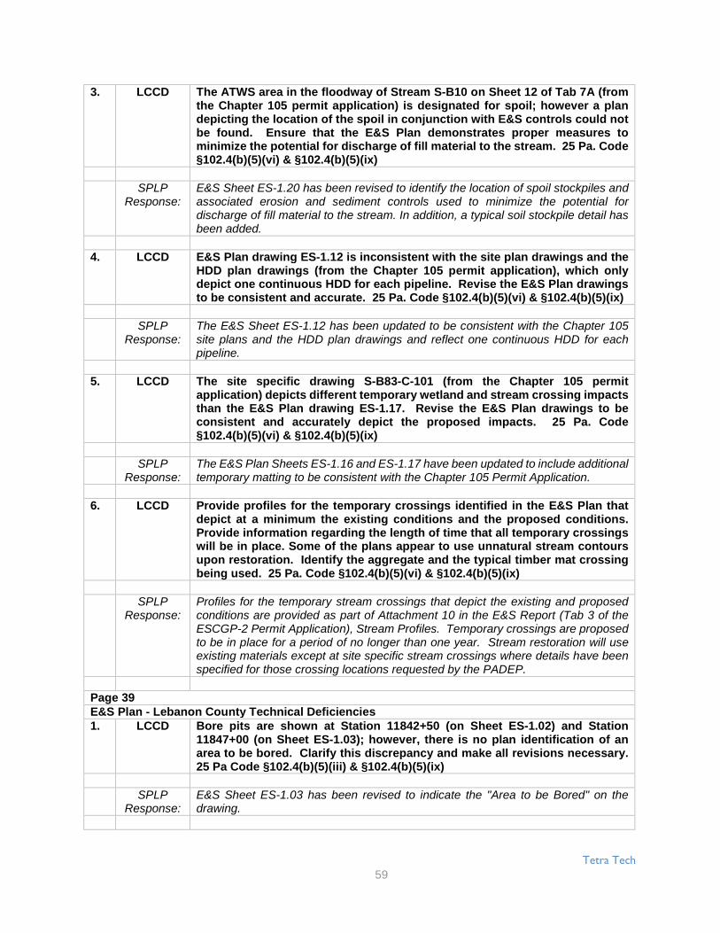
Tetra Tech
59
3. LCCD The ATWS area in the floodway of Stream S-B10 on Sheet 12 of Tab 7A (fromthe Chapter 105 permit application) is designated for spoil; however a plandepicting the location of the spoil in conjunction with E&S controls could notbe found. Ensure that the E&S Plan demonstrates proper measures tominimize the potential for discharge of fill material to the stream. 25 Pa. Code§102.4(b)(5)(vi) & §102.4(b)(5)(ix)
SPLPResponse:
E&S Sheet ES-1.20 has been revised to identify the location of spoil stockpiles andassociated erosion and sediment controls used to minimize the potential fordischarge of fill material to the stream. In addition, a typical soil stockpile detail hasbeen added.
4. LCCD E&S Plan drawing ES-1.12 is inconsistent with the site plan drawings and theHDD plan drawings (from the Chapter 105 permit application), which onlydepict one continuous HDD for each pipeline. Revise the E&S Plan drawingsto be consistent and accurate. 25 Pa. Code §102.4(b)(5)(vi) & §102.4(b)(5)(ix)
SPLPResponse:
The E&S Sheet ES-1.12 has been updated to be consistent with the Chapter 105site plans and the HDD plan drawings and reflect one continuous HDD for eachpipeline.
5. LCCD The site specific drawing S-B83-C-101 (from the Chapter 105 permitapplication) depicts different temporary wetland and stream crossing impactsthan the E&S Plan drawing ES-1.17. Revise the E&S Plan drawings to beconsistent and accurately depict the proposed impacts. 25 Pa. Code§102.4(b)(5)(vi) & §102.4(b)(5)(ix)
SPLPResponse:
The E&S Plan Sheets ES-1.16 and ES-1.17 have been updated to include additionaltemporary matting to be consistent with the Chapter 105 Permit Application.
6. LCCD Provide profiles for the temporary crossings identified in the E&S Plan thatdepict at a minimum the existing conditions and the proposed conditions.Provide information regarding the length of time that all temporary crossingswill be in place. Some of the plans appear to use unnatural stream contoursupon restoration. Identify the aggregate and the typical timber mat crossingbeing used. 25 Pa. Code §102.4(b)(5)(vi) & §102.4(b)(5)(ix)
SPLPResponse:
Profiles for the temporary stream crossings that depict the existing and proposedconditions are provided as part of Attachment 10 in the E&S Report (Tab 3 of theESCGP-2 Permit Application), Stream Profiles. Temporary crossings are proposedto be in place for a period of no longer than one year. Stream restoration will useexisting materials except at site specific stream crossings where details have beenspecified for those crossing locations requested by the PADEP.
Page 39E&S Plan - Lebanon County Technical Deficiencies1. LCCD Bore pits are shown at Station 11842+50 (on Sheet ES-1.02) and Station
11847+00 (on Sheet ES-1.03); however, there is no plan identification of anarea to be bored. Clarify this discrepancy and make all revisions necessary.25 Pa Code §102.4(b)(5)(iii) & §102.4(b)(5)(ix)
SPLPResponse:
E&S Sheet ES-1.03 has been revised to indicate the "Area to be Bored" on thedrawing.

Tetra Tech
60
2. LCCD A temporary equipment bridge appears to be intersecting an existingroad/driveway at Station 12012+00 on Sheet ES-1.14. Identify how the existingroad/driveway will continue to function during use of the temporaryequipment bridge. 25 Pa Code §102.4(b)(5)(iii), §102.4(b)(5)(vi) &§102.4(b)(5)(ix)
SPLPResponse:
The temporary equipment bridge has been replaced with rock constructionentrances on both sides of the north-south road.
3. LCCD The E&S Plan sheets indicate that wetland J47 is within both Dauphin andLebanon Counties. Clarify if all of the proposed impacts to this wetland areaccounted for in the Dauphin County Application. Revise the impact plandrawing to depict the county boundary and accurately identify the impacts tothe wetland in Lebanon County. In addition, it is recommended that theDauphin County E&S Plan be evaluated and revised for consistency asnecessary. 25 Pa Code §102.4(b)(5)(iii) & §102.4(b)(5)(ix)
SPLPResponse:
The E&S Plan Sheet ES-1.01 has been revised to match the Chapter 105 PermitApplication and depict WL-J47 as being impacted in Dauphin County only.
4. LCCD The impact plans and impact table (from the Chapter 105 permit application)indicate temporary impacts from a temporary bridge are proposed to streamS-A49. However, the E&S Plan does not depict any proposed temporaryimpacts. Revise the E&S Plan to depict any proposed temporary impacts tostream S-A49 and clarify what permanent impacts are proposed beyond theHDD installed pipelines. 25 Pa Code §102.4(b)(5)(iii), §102.4(b)(5)(v),§102.4(b)(5)(vi) & §102.4(b)(5)(ix)
SPLPResponse:
The E&S Plan Sheet ES-1.02 has been updated to depict temporary matting acrossS-A49 within the ROW.
5. LCCD The plans (from the Chapter 105 permit application) indicate that Streams S-B77, S-A2, S-A3, S-A5, S-A10, and S-H7 flow in and along and under the ROWand proposed pipelines and not across and immediately through them. TheE&S Plan does not provide sufficient detail on the stream limits, banks, andexcavation limits etc. Provide site-specific plans, cross sections, and profilesthat adequately depict the existing and proposed conditions, stream bed,stream banks, limits of excavation, and methods for the stream restorations.25 Pa Code §102.4(b)(5)(vi) & §102.4(b)(5)(ix)
SPLPResponse:
Site specific plan drawings, cross sections, and profiles have been prepared forthese crossings which depict the existing and proposed conditions, stream bed,stream bank, limits of excavation, and method for stream restoration. See SiteSpecific Details at the end of the E&S and Site Restoration Plan set in Attachment2 of the E&S Report (Tab 3 of the ESCGP-2 Permit Application).
6. LCCD The HDD plan drawing PA-LE-0055.0000-RD (from the Chapter 105 permitapplication) indicates that the HDD Entry/Exit point will be located withinwetland A13. However, the site impact plan drawings (from the Chapter 105permit application) and the E&S Plan drawing depict that this entry exit pointwill not be located within this wetland. Revise and clarify the E&S Plandrawings to be consistent and accurately reflect the proposed impacts. 25 PaCode §102.4(b)(5)(iii), §102.4(b)(5)(v), §102.4(b)(5)(vi) & §102.4(b)(5)(ix)

Tetra Tech
61
SPLPResponse:
The HDD plan drawing PA-LE-0055.000-RD has been revised to be consistent withthe impact plan drawings and the E&S Plan drawings and shows the HDD entry/exitpoint outside of wetland W-A13.
Page 407. LCCD The stream banks of S-A25 are not depicted on the E&S Plan drawing ES-1.50.
Based on the width of the stream, it appears that this stream may be partiallylocated within the permanent ROW on the southern portion of the proposedROW. Revise the E&S Plan drawing to depict the proposed stream banks andany proposed impacts to the stream from the meander of the stream re-entering the proposed ROW. 25 Pa Code §102.4(b)(5)(iii), §102.4(b)(5)(v),§102.4(b)(5)(vi) & §102.4(b)(5)(ix)
SPLPResponse:
A site specific detail has been prepared at this location. See Sheets S-A25-A andS-A25-B.
8. LCCD The Site Plan drawing and impact table (from the Chapter 105 permitapplication) state that the stream crossing S-A27 will be a dry crossing;however, the site plan drawing, sheet 30 (from the Chapter 105 permitapplication), and E&S Plan drawing ES-1.53 depict that the stream will havetemporary timber mat bridge crossing and that the pipelines will be boredunderneath the stream. Revise the E&S Plan to be consistent and accurate towhat is proposed, and include a site specific/auger bore drawing for thiscrossing. 25 Pa Code §102.4(b)(5)(iii), §102.4(b)(5)(v), §102.4(b)(5)(vi) &§102.4(b)(5)(ix)
SPLPResponse:
The Stream S-A27 has been verified to be crossed by a conventional bore. TheChapter 105 site plans drawings, impact table, and E&S Sheet ES-1.53 have beenupdated to reflect the bore under the stream.
9. LCCD The ATWS area in the floodplain and floodway of Stream S-A24 on Sheet 26 ofTab 7A (from the Chapter 105 permit application) is designated for spoil;however, a plan depicting the location of the spoil in conjunction with E&Scontrols could not be found. Ensure that the E&S Plan demonstrates propermeasures to minimize the potential for discharge of fill material to streams.25 Pa Code §102.4(b)(5)(vi) & §102.4(b)(5)(ix)
SPLPResponse:
E&S Sheet ES-5.47 has been revised to identify the location of spoil stockpiles andassociated erosion and sediment controls used to minimize the potential fordischarge of fill material to the stream. A spoil stockpile detail has been added toE&S Sheet ES-0.09.
10. LCCD E&S Plan drawing ES-1.32 identifies that stream S-A17, which is 25-feet wide,will be temporarily crossed with timber mats. Explain how timber mats will beutilized to construct a temporary bridge of this length. 25 Pa Code§102.4(b)(5)(vi) & §102.4(b)(5)(ix)
SPLPResponse:
A site specific detail has been prepared at this location for Stream S-A17. SeeSheets S-A17-A and S-A17-B.

Tetra Tech
62
E&S Plan - Perry County Technical Deficiencies1. PCCD E&S Plan drawing ES-3.09 and C-2 of the Doylesburg Station E&S Plan do not
identify the temporary impacts indicated on Sheet 6 of Tab 7A (from theChapter 105 permit application). Ensure that the E&S Plans properly identifyall of the proposed activities. 25 Pa Code §102.4(b)(5)(iii), 1 §02.4(b)(5)(v),§102.4(b)(5)(vi) & §102.4(b)(5)(ix)
SPLPResponse:
The temporary impacts shown on Sheet 6 of Tab 7A are shown on E&S PlanDrawings ES-3.10 not ES-3.09. The impacts are not shown on C-2 of the DoylesburgStation E&S plan because it is outside the view of the plan sheet.
2. PCCD The plans (from the Chapter 105 permit application) indicate that Streams S-K51, S-K52, S-Q64, S-Q67, S-J63, S-J62, a portion of S-J70, and S-J69 flow inand along and under the ROW and proposed pipelines and not across andimmediately through them or start/end in the area of excavation for the pipes.The plan (from the Chapter 105 permit application) provided for S-Q67 in Tab7D does not adequately depict the existing or proposed conditions uponstream restoration or excavation limits. The E&S Plans does not providesufficient detail on the stream limits, banks, excavation limits, etc. Providesite-specific plans, cross sections, and profiles that adequately depict theexisting and proposed conditions, stream bed, stream banks, limits ofexcavation, and methods for the stream restorations. 25 Pa Code§102.4(b)(5)(vi) & §102.4(b)(5)(ix)
SPLPResponse:
Site specific plan drawings, cross sections, and profiles have been prepared forthese crossings which depict the existing and proposed conditions, stream bed,stream bank, limits of excavation, and method for stream restoration. See SiteSpecific Details at the end of the E&S and Site Restoration Plan set in Attachment2 of the E&S Report (Tab 3 of the ESCGP-2 Permit Application).
Page 413. PCCD Stream S-J70 is delineated as being within the Temporary ROW on E&S Plan
drawing ES-3.27 and outside of the Temporary ROW on plan sheet 17 (fromthe Chapter 105 permit application). Revise the E&S Plan to be accurate withthe site plan (from the Chapter 105 permit application). 25 Pa Code§102.4(b)(5)(v) & §102.4(b)(5)(ix)
SPLPResponse:
ES-3.27 has been revised to accurately reflect Stream S-J70 as delineated outsideof the Temporary ROW.
4. PCCD The E&S Plan drawing ES-3.03 does not have all of wetlands L1 and L2delineated in the March 2016 Aquatic Resource Report Addendum (from theChapter 105 permit application). In addition, this plan sheet does not depictstream S-Q70. Revise the E&S Plan drawings to accurately delineate thestreams and wetlands. 25 Pa Code §102.4(b)(5)(v) & §102.4(b)(5)(ix)
SPLPResponse:
E&S Plan drawing ES-3.03 has been updated to depict all of the Wetlands L1 andL2 as delineated in the March 2016 Aquatic Resource Report Addendum. StreamS-Q70 has been added to ES-3.03 as well.
5. PCCD The E&S Plan drawing ES-3.1 delineates streams S-K51 and S-K53 differentlythan the delineation report and site plan drawings (from the Chapter 105permit application). Revise the E&S Plan to accurately delineate and depictthese watercourses, their floodways, and the proposed impacts. 25 Pa Code§102.4(b)(5)(v) & §102.4(b)(5)(ix)

Tetra Tech
63
SPLPResponse:
ES-3.1 has been revised to accurately delineate Streams S-K51 and S-K53and beconsistent with the Chapter 105 permit application. The streams’ floodways andproposed impacts have been revised as necessary.
6. PCCD E&S Plan drawing ES-3.10 identifies that stream S-K53, which is 25-feet wide,will be temporarily crossed with timber mats. Explain how timber mats will beutilized to construct a temporary bridge of this length. 25 Pa Code§102.4(b)(5)(vi) & §102.4(b)(5)(ix)
SPLPResponse:
The crossing Stream S-K53 on ES-3.10 has been revised to indicate that atemporary equipment crossing will be utilized. The temporary equipment crossingtypical details, provided on ES-0.10, provide the contractor the ability to use a bridgewithout a center span up to 40 feet or culvert the crossing.
7. PCCD E&S Plan sheet ES-3.17 identifies that a bore pit is partially located withinwetland W-25e; however, the site specific bore plan PPP-PA-PE-0010.0000-AR(from the Chapter 105 permit application) depicts that all bore pits will belocated outside of wetlands. Revise the E&S Plan to be consistent andaccurate. 25 Pa Code §102.4(b)(5)(vi) & §102.4(b)(5)(ix)
SPLPResponse:
ES-3.17 has been revised so that the bore pit has been moved out of the wetland.
8. PCCD The site specific plan drawing S-Q66-S-Q67-C-101 (from the Chapter 105permit application) depicts different temporary crossings with timber mattingthan the E&S Plan sheet ES-3.17. Revise the E&S Plan to be consistent andaccurate. 25 Pa Code §102.4(b)(5)(vi) & §102.4(b)(5)(ix)
SPLPResponse:
The timber matting on E&S Plan Sheet ES-3.17 has been revised to match theChapter 105 Permit Application.
9. PCCD E&S Plan sheet ES-3.22 does not accurately delineate wetland J-70 asdelineated in the March 2016 Aquatic Resource Report Addendum (from theChapter 105 permit application). Revise the E&S Plan drawings to accuratelydelineate this wetland. 25 Pa Code §102.4(b)(5)(v) & §102.4(b)(5)(ix)
SPLPResponse:
Wetland WL-J70 has been updated on ES-3.22 to accurately depict the wetland asdelineated in the March 2016 Aquatic Resource Report Addendum from the Chapter105 Permit Application.
Page 4210. PCCD E&S Plan sheet ES-3.31 identifies that the proposed temporary timber mat
stream crossing over stream S-J62 is in excess of 100-feet in length acrossthe stream. Explain how timber mats will be utilized to construct a temporarybridge of this length. 25 Pa Code §102.4(b)(5)(vi) & §102.4(b)(5)(ix)
SPLPResponse:
A site specific detail has been prepared at this location for Stream S-J62. Seesheets S-J62-A and S-J62-B.
11. PCCD E&S Plan sheet ES-3.31 does not delineate stream S-J62 as it is delineated onthe Aquatic Resource Report delineation or the site plan drawings (from theChapter 105 permit application). Revise the E&S Plan to accurately delineatethis stream and accurately depicts the stream banks. 25 Pa Code§102.4(b)(5)(v) & §102.4(b)(5)(ix)

Tetra Tech
64
SPLPResponse:
Stream S-J62 has been updated on Sheet ES-3.31 to match the Chapter 105 permitapplication and the Aquatic Resource Report. A site specific drawing has beenprovided on sheet S-J62-A and S-J62-B.
12. PCCD The ATWS areas in the floodway of Stream S-K80 on Sheet 2 of Tab 7A (fromthe Chapter 105 permit application) are designated for spoil; however, a plandepicting the location of the spoil in conjunction with E&S controls could notbe found. Ensure that the E&S Plan demonstrates proper measures tominimize the potential for discharge of fill material to the stream. In addition,the western ATWS is located in the stream; however, the impact table (fromthe Chapter 105 permit application) does not identify any temporary impacts.Revise the E&S Plan as necessary. 25 Pa Code §102.4(b)(5)(v), §102.4(b)(5)(vi)& §102.4(b)(5)(ix)
SPLPResponse:
See Juniata County Technical Deficiencies #1 (Page 37, #1).
13. PCCD The site plan drawing on Sheet 20 of Tab 7A (from the Chapter 105 permitapplication) and E&S Plan drawing ES-3.32 appear to indicate that stream S-J64 is proposed to be crossed by the proposed pipelines where it currentlyflows underneath and/or alongside Meadow Road. Provide detailed plans,cross sections, and profiles for the construction of the proposed pipelinesand temporary crossing which depict existing and proposed conditions. Thisincludes plans and profiles for any culvert or bridge carrying stream S-J64underneath Meadow Road. 25 Pa Code §102.4(b)(5)(iii), §102.4(b)(5)(v),§102.4(b)(5)(vi) & §102.4(b)(5)(ix)
SPLPResponse:
The temporary equipment crossing has been removed. Stream S-J64 is anephemeral stream running through a culvert on a DCNR SF property. The DCNRrequested that SPLP cut most of the DCNR roads, as opposed to boring.
E&S Plan - Doylesburg Pump Station Technical Deficiencies1. PCCD The following technical deficiencies are associated with Sheet C-2: 25 Pa Code
§102.4(b)(5)(ix)a. Verify that all of the Detail Indicators have correct references (e.g. rock filter
& rock construction entrance).
SPLPResponse:
The detail indicators were checked and updated as necessary to ensure they havecorrect references.
b. Proposed grading is shown outside the limit of disturbance for the channelon the east side of the site. Ensure that all earth disturbances are shownwithin the limit of disturbance. Make all revisions necessary. 25 Pa Code§102.4(b)(5)(iii)
SPLPResponse:
There are no proposed features or grading outside of the LOD. This has beenclarified by revising drawing line types, which may have made it appear that gradingwas to occur outside the LOD.
Page 43c. Clearly identify the existing features versus the proposed features. 25 Pa
Code §102.4(b)(5)(iii)

Tetra Tech
65
SPLPResponse:
Existing features are shown with a light grey line type and all proposed features areshown with a black line type to clarify existing versus proposed features.
2. PCCD Provide a more specific sequence of construction, including site specificinformation and the specific BMPs that will be employed during each stage ofconstruction. 25 Pa Code §102.4(b)(5)(vii)
SPLPResponse:
The construction sequence was made more specific by including more site specificinformation and the specific BMPs that will be employed during each stage ofconstruction.
3. PCCD Remove "as needed" from Stage 2 of the sequence of construction for theinstallation of rock construction entrance. This location of this E&S BMP isprovided on the plan drawings and it is to be utilized where equipment/trafficwill exit the site. 25 Pa Code §102.4(b)(5)(vii) & §102.4(b)(5)(xiv)
SPLPResponse:
The phrase “as needed” has been removed.
4. PCCD Remove the reference of silt fence and other BMP from Stage 5 of thesequence of construction. This site located in a special protection watershed(Sherman Creek; HQ-CWF); ABACT BMPs are to be provided and utilized. Analternative would be to provide the necessary information (details, notes, planview, etc.) to upgrade the silt fence to an ABACT rating using additional E&SBMPs (refer to Page 75 of the E&S Manual). 25 Pa Code §102.4(b)(5)(vi),§102.4(b)(5)(vii), §102.4(b)(5)(ix), §102.4(b)(5)(x), §102.4(b)(6)(ii) & §102.11(a)(1)
SPLPResponse:
References to silt fence has been removed from the construction sequence. Siltfence will not be used at the Doylesburg station. ABACT BMPs have been specifiedin the Plans.
5. PCCD The proposed rock filters provided in the Rock Filters detail on Sheet C-4 arenot ABACT rated. In order to be raised to an ABACT rating, the rock filters areto be provided with a 6-in layer of compost on the upslope side (refer to Page92 of the E&S Manual). Revise the rock filter detail so that the E&S BMPconforms to the ABACT rating for use in the special protection watershed. 25Pa Code §102.4(b)(5)(vi), §102.4(b)(5)(ix), §102.4(b)(6)(ii) & §102.11(a)(1)
SPLPResponse:
The detail has been revised to show the 6-inch layer of compost on the upslope sideof the rock filters.
6. PCCD The Rock Filters detail provided on Sheet C-4 references a Channel C. IdentifyChannel C on the plan view and if Channel C is proposed, provide a detail forChannel C. 25 Pa Code §102.4(b)(5)(iii) & §102.4(b)(5)(ix)
SPLPResponse:
The plan has been revised to indicate that the rock filters will be placed in the existingchannel C.
7. PCCD Provide calculations, including the drainage area delineations, for eachproposed channel, DEP recommends utilizing Standard E&S Worksheet #11in Appendix B of the E&S Manual. 25 Pa Code §102.4(b)(5)(viii) & §102.11(a)
SPLPResponse:
Worksheet #11 has been filled out for the proposed channels.

Tetra Tech
66
8. PCCD Revise the county reference from Huntingdon to Perry in Section 2.0 on Page2-1 of the E&S Plan Narrative. 25 Pa Code §102.4(b)(5)(iii)
SPLPResponse:
The county reference has been revised to indicate Perry County.
Page 44E&S Plan - York County Technical Deficiencies1. YCCD Provide site specific instructions to address how the contractor will open
trench, bypass the stream flow and restore the 80' wide stream crossing at S-H56. Identify how timber mats will be able to be used at this location, as theexisting conditions were observed as an approximately 80' wide boulderstrewn field consisting of diabase material. 25 Pa Code §102.4(b)(5)(vi),§102.4(b)(5)(vii) & §102.4(b)(5)(ix)
SPLPResponse:
A site specific plan drawing of stream S-H56 has been created and can be found onE&S Sheets S-H56-A and S-H56-B.
2. YCCD The waterbars in several locations appear to outlet back onto the right-of-way(e.g. east of stream crossing S-H67, between Stations 10960+00 and 10967+00,between Station 11130+70 and stream crossing S-H59). Provide additionalBMPs if the waterbars cannot be extended to discharge the runoff off the right-of-way. 25 Pa Code §102.4(b)(5)(vi) & §102.4(b)(5)(ix)
SPLPResponse:
Several waterbars have been re-oriented for better discharge off the right-of-way onE&S Sheet ES-4.08.
3. YCCD Provide discussion related to the use of compost filter sock at Stations10980+70 & 10984+70, as it t appears that concentrated flow will be directedto the compost filter sock. 25 Pa Code §102.4(b)(5)(vi) & §102.4(b)(5)(ix)
SPLPResponse:
A temporary upslope diversion berm has been added to that area and clean waterflow directed to 18" CFS which will function as a level spreader to address this areaon ES-4.09.
4. YCCD Identify how access will be maintained for the existing driveways androadways crossings (e.g. Stations 11011+25, 11086+60, 11107+15, 11111+75,11119+75 & 11139+25). 25 Pa Code §102.4(b)(5)(iii) & §102.4(b)(5)(ix)
SPLPResponse:
Access to these existing driveways and trails will be maintained by having roadplates available to use for crossing the trench. If requested by the owner, the trenchcan be plated during off hours to allow access by the landowner. The road surfacewill be restored in accordance with the landowner agreement.
5. YCCD The slope length to the 12" compost filter sock located along the on the eastside of stream crossing S-H60, between Station 11147+00 and stream crossingS-H58 & in the area of stream crossing S-H58 exceed the maximum allowableslope length for the percent slope. Provide an appropriately size E&S BMP inthese locations. 25 Pa Code §102.4(b)(5)(vi), §102.4(b)(5)(viii) &§102.4(b)(5)(ix)

Tetra Tech
67
SPLPResponse:
All E&S BMPs were verified and shown on the plans. Clean water diversions,waterbars, and appropriately sized CFS are shown.
6. YCCD An existing linear clearing is shown to the south of the proposed pipelinestarting at Station 11154+00 (on Sheet ES-4.19) and continuing along to thesouth of the proposed pipeline and then crosses the proposed pipeline atStation 11167+00 (on Sheet ES-4.20). Identify what this existing clearing is for(i.e. existing trail, existing above ground utility, existing below ground utility,etc.). 25 Pa Code §102.4(b)(5)(iii) & §102.4(b)(5)(ix)
SPLPResponse:
The linear clearing south of the proposed pipeline on ES-4.19 and ES-4.20 is anexisting pipeline.
7. YCCD It appears that there is a portion of the disturbed area near the proposed borepits at Station 11169+50 (on Sheet ES-4.20) that would not be managed by anE&S BMP, due to the close proximity of the bore pits to the existing stream.Clarify this discrepancy. 25 Pa Code §102.4(b)(5)(iii), §102.4(b)(5)(vi) &§102.4(b)(5)(ix)
SPLPResponse:
Additional compost filter sock has been added near the bore pits at Station11169+50 (on Sheet ES-4.20).
Page 45Site Restoration and PCSM Plan Narrative - Pennsylvania Pipeline Project - South Central Region:Spreads 3, 4, 51. DEP Page 1 is confusing, as it is not clear what this narrative covers. Clearly
identify if this narrative covers just the areas that require a PCSM Plan (blockvalve, stations, etc.) or if the narrative covers the site restoration of themainline project (under site restoration) and the areas that require a PCSMPlan. 25 Pa Code §102.8(f)(3)
SPLPResponse:
The Introduction on Page 1 has been revised to provide clarification. The narrativecovers both the areas that will require site restoration as well as the areas thatrequire a PCSM Plan. The site restoration portion of the Site Restoration and Post-Construction Stormwater Management Plan (the “Plan”) (Section 3.0) will ensureprompt and effective stabilization of the pipeline right-of-way, associatedworkspaces, and temporary access roads following pipeline construction, and thePCSM portion of the Plan (Section 4.0) will manage stormwater runoff from thepermanent aboveground facilities (block valve sites) associated with the Project.
2. DEP Identify the source and cause of an impairment for any stream which isimpaired and not just for the siltation impaired streams. Make all revisionsnecessary. 25 Pa Code §102.8(f)(5)
SPLPResponse:
Table 1 has been updated to include the causes of impairments for the receivingwaters that receive runoff from the proposed block valves.
3. DEP Section 2.0 on Page 2 references "This site E&S and Site Restoration Plan..."This is the narrative for post construction. The PCSM Plan shall be separatefrom the E&S Plan and the E&S Plan shall be separate from the PCSM Plan.Make all revisions necessary. 25 Pa Code §102.4(b)(5)(xiv) & §102.8(d)
SPLPResponse:
Section 2.0 has been revised to remove the reference to the E&S Plan. The E&SPlan is a separate document from the Site Restoration and Post-ConstructionStormwater Management Plan.

Tetra Tech
68
4. DEP Section 2.0 on Page 2 references 24 new block valve locations, 3 stationvalves, 1 substation and 3 additional block valves at existing facilities (for atotal of 31 sites); however, Table 1 in Attachment 5 only lists 30 sites. Clarifythis discrepancy. 25 Pa Code §102.8(f)(3)
SPLPResponse:
An explanation for the total number of block valve sites versus the ones that requirePCSM is now included in the narrative.
5. DEP Section 2.0 on Page 2 is not clear if the 3 additional block valves at the existingfacilities are included in the earth disturbance for the project. Clearly identifyif these block valves are included or not; if not, include them in the ESCGP-2Permit Boundary. Make all revisions necessary. 25 Pa Code §102.5(c) &§102.8(f)(3)
SPLPResponse:
An explanation for the total number of block valve sites versus the ones that requirePCSM is now included in the narrative. PCSM calculations have been performedfor each block valve that proposes new impervious cover. All block valves areincluded in the earth disturbance for the project.
6. DEP Section 2.1 on Page 4 is not specific to the locations cover by this Plan.Ensure that Plan is related to portions for which is covered by this Plan andESCGP-2 Permit (i.e. Monongahela River and Cambria County are outside ofthis Permit application). 25 Pa Code §102.8(f)(3)
SPLPResponse:
Section 2.1 on page 4 of the narrative has been updated to reflect topography withinthe southcentral region that the proposed project traverses.
7. DEP Section 2.3 on Page 5 provides for soil resolutions, but does not identify thesite specific soils or their limitations. Provide the site specific soils,limitations and appropriate resolution for this soil limitation for the postconstruction condition and how the project was designed to address thelimitation for the PCSM BMPs. 25 Pa Code §102.8(f)(2), §102.8(f)(12) &§102.8(g)(5)
SPLPResponse:
Tables summarizing the site-specific soils, their limitations, and appropriateresolution to address soil limitations for site restoration and the post-constructioncondition have been added to Attachment 2.
8. DEP Section 2.3 on Page 5 identifies that the receiving surface waters can be seenon the maps and drawings in Attachments 1 & 2; however, the maps anddrawings provided in Attachments 1 & 2 do not clearly identify the receivingsurface waters. Clearly identify the receiving surface waters as indicated inthe narrative. 25 Pa Code §102.8(f)(5) & §102.8(f)(9)
SPLPResponse:
An additional set of USGS location maps has been added to Attachment 1. Themaps show and label all delineated streams that the project traverses.
Page 469. DEP Section 2.3 on Page 5 references to see the E&S Plan. The PCSM Plan shall be
separate from the E&S Plan and the E&S Plan shall be separate from the PCSMPlan. Make all revisions necessary. 25 Pa Code §102.4(b)(5)(xiv) & §102.8(d)

Tetra Tech
69
SPLPResponse:
The reference to the Erosion and Sediment Control plan has been removed.
10. DEP The following technical deficiencies are associated with the constructionsequence in Section 3.1 starting on Page 7: 25 Pa Code §102.8(f)(7)
a. It is identified that "It is not intended that the drawings and this reportshow detailed information on methods and materials." This statementdoes not meet regulations. The E&S and PCSM Plans shall be final forconstruction, and the information, details and provide the methods andmaterials to properly construct and implement the Plans, including theBMPs, within the construction sequences associated with these Plans. 25Pa Code §102.4(b)(5)(xiv) & §102.8(d)
SPLPResponse:
The referenced statement has been removed from the Plan.
b. The narrative identifies that the contractor can deviate from the authorizedE&S and PCSM Plans based upon field conditions. A deviation from theauthorized plans may be necessary under certain limited circumstances;however, the appropriate county conservation district and DEP have toapprove any deviation to the authorized plans. Make all revisionsnecessary to clearly identify this requirement.
SPLPResponse:
Language has been added to the construction sequence to specify that theappropriate county conservation district and DEP shall be contacted and mustapprove any deviation from the authorized plans.
c. Provide a schedule of inspections for critical stages of PCSM BMPinstallation with the construction sequence.
SPLPResponse:
Installation of PCSM BMPs is discussed in Section 4.1 The schedule for inspectionsand maintenance of PCSM BMPs is provided in Section 4.5.
11. DEP More information is required to properly identify what the "Adverse Sites" areor how to identify them in Permanent Seeding sections in Section 3.1 on Page7 and Section 4.1 on Page 18. 25 Pa Code §102.8(f)(6)
SPLPResponse:
Sections 3.1 and 4.1 have been updated to provide an explanation of adverse sitesso the appropriate seeding rate can be determined onsite.
12. DEP Footnote 7 on Pages 8 & 19 for the Permanent Seeding section tablesreferences extreme southeastern and extreme southwestern areas. If this isnot applicable to the area covered by this ESCGP-2 Permit, then remove thereference. If this is applicable to the area covered by this ESCGP-2 Permit,then provide a more specific reference as to where it is acceptable. 25 PaCode §102.8(f)(6)
SPLPResponse:
Footnote 7 of the Permanent Seeding section has been removed because it doesnot apply to the Project. The footnotes have been renumbered, and seed mixture 9has been removed from the table that recommends seed mixtures for site conditions.

Tetra Tech
70
13. DEP Section 3.2 on Page 11 and Section 4.2 on Page 22 are not sufficient as theydo not provide for procedures which ensure that the proper measures forrecycling or disposal of materials associated with or from the PCSM BMPs arein accordance with Department laws, regulations and requirements. 25 PaCode §102.8(f)(11)
SPLPResponse:
Section 3.2 has been revised to be specific to recycling and disposal of materialsassociated with site restoration activities. Section 4.2 has been revised to provideinformation specific recycling and disposal of materials associated with or resultingfrom PCSM BMPs.
14. DEP Section 3.3 on Page 11 is not sufficient as there is no clear demonstration thatthe thermal impacts will be mitigated by the minimized clearing duringconstruction and by permanent stabilization as soon as practicable. Thisthermal impact analysis appears to be more for the E&S Plan than for thePCSM Plan. Provide an appropriate thermal impact analysis specific to thePCSM Plan for this location. 25 Pa Code §102.8(f)(13)
SPLPResponse:
Section 3.3 has been updated to provide a discussion of thermal impacts specific tothe site restoration phase of the project. The thermal impact analysis for the PCSMphase of the project is provided in Section 4.3 of the narrative.
Page 4715. DEP Section 3.4 on Page 11 and Section 4.4 on Page 29 provide information related
to the riparian buffer/riparian forest buffer waiver request. Identify if thisinformation is in addition to the information provided with the NOI. Provideall riparian/riparian forest buffer waiver request information in one placetogether. 25 Pa Code §102.14(d)(2) & §102.14(d)(3)
SPLPResponse:
Sections 3.4 and 4.4 are intended to be a summary of the information provided withthe NOI. The riparian forest buffer waiver request within the NOI provides allinformation in one location.
16. DEP Section 3.5 on Page 13 appears to have information related to the E&S Planand activities during construction are included in this narrative. The PCSMPlan shall be separate from the E&S Plan and the E&S Plan shall be separatefrom the PCSM Plan. 25 Pa Code §102.4(b)(5)(xiv), §102.8(d) & §102.8(f)(10)
SPLPResponse:
Section 3.5 has been revised to remove references to E&S BMPs. This section isnow specific to inspection and maintenance during site restoration activities.
17. DEP If the information provided in Section 3.9 is not a sufficient antidegradationanalysis. The narrative identifies that non-discharge alternatives wereevaluated; however, there is no discussion related to show what wasevaluated. It appears that the discussion is focus on the E&S Plan and duringthe earth disturbance activities; provide an antidegradation analysis for thePCSM Plan. Provide an antidegradation analysis for each point of dischargethat requires one. 25 Pa Code §102.8(d), §102.8(f)(6) & §102.8(h)
SPLPResponse:
Section 3.6 has been expanded to discuss the non-discharge alternatives and Dueto the linear nature of this project all of the HQ/EV special protection watershedsreceived the same non discharge alternative evaluation and incorporation of ABACTsite restoration BMPs was applied throughout the pipeline.

Tetra Tech
71
18. DEP The narrative discussion in Section 3.7 on Page 14 is not clear as to what isbeing discussed; site restoration or post construction. If the activities are siterestoration and meet 25 Pa Code §102.8(n), then a stormwater analysis is notrequired. If the activities are site restoration and the Site Restoration Plan wasplanned and designed to 25 Pa Code §102.8(n), then clearly identify that assuch along with which areas are included in the Site Restoration Plan. 25 PaCode §102.8
SPLPResponse:
Section 3.7 has been revised to clarify the intent of the section. The sectionaddresses site restoration activities which were planned and designed inaccordance with 25 Pa Code § 102.8(n). All areas of the project, excluding thepermanent block valve sites and associated permanent access roads, areaddressed by Section 3.7.
19. DEP The following technical deficiencies are related to the restoration activitiesduring the earth disturbance activities (as part of the E&S Plans) and postconstruction (as part of the Site Restoration Plans):
a. A Site Restoration Plan narrative shall be provided for the mainlinepipeline construction. This narrative can be part of the E&S Plan narrativefor the mainlines, and it is required to be in conformance with 25 Pa. Code§102.8(n). §102.8(b), §102.8(c), §102.8(e), §102.8(f), §102.8(h), §102.8(i),§102.8(l) & §102.8(m)
SPLPResponse:
A site restoration narrative has been added to the E&S plan for the mainline pipelineconstruction. In addition, Section 3.0 of the Site Restoration and Post-ConstructionStormwater Management Plan discusses site restoration for the mainline pipeline.The narratives are in conformance with the E&S Plan for the project.
b. Provide more identification in the narratives and on the plan drawingsrelated to topsoil segregation. 25 Pa Code §102.8(f)(3), §102.8(f)(6) &§102.8(f)(9)
SPLPResponse:
Topsoil will be stockpiled separate from subsoil in all areas where topsoil is present.Specific topsoil stockpile locations will be determined during construction but willconform to the requirements in the general notes and details on the plan drawings.The right of way detail shows the general topsoil stockpile location relative to thepipe trench and subsoil stockpile, and the soil stockpile detail shows the perimeterE&S BMPs that shall be installed downslope of topsoil stockpiles. The siterestoration construction sequence has been updated to provide specifications forbackfilling topsoil after final grades are established.
Page 48c. Provide more identification in the narratives and on the plan drawings
related to loosening of compacted soils prior to topsoil placement andstabilization (at the temporary access roads, topsoil stockpiles, accessroutes along the mainline, etc.). 25 Pa Code §102.8(f)(3), §102.8(f)(6) &§102.8(f)(9)
SPLPResponse:
The site restoration construction sequence has been updated in the Site Restorationand Post-Construction Stormwater Management Plan narrative and on theapplicable drawing sets. The sequence now specifies chisel plowing orincorporating soil amendments where compaction occurs. The sequence alsospecifically addresses restoration of access roads.

Tetra Tech
72
d. Provide a discussion of measures that will be taken to avoid and minimizecompaction to the maximum extent practicable and where compactionoccurs, what measures will be taken to ensure adequate infiltration andsuccessful vegetation of the right of way. §102.8(b) & §102.22. TheDepartment recommends you evaluate Section 6.7 (Restoration BMPs) ofthe PCSM Manual. Ensure notes are included on the drawings and in thedocuments that will be provided to the construction contractors.
SPLPResponse:
Compaction concerns are restricted to the limit of disturbance, which has beenminimized to the maximum extent practicable. Within the pipeline right of way, travellanes will be utilized to restrict the extent of compaction. Following installation of thepipeline, deep ripping or chisel plowing will occur to alleviate compaction, promoteinfiltration, and facilitate vegetative growth. The site restoration constructionsequence has been updated in the Site Restoration and Post-ConstructionStormwater Management Plan narrative and on drawing PCS-0.01. The sequencenow specifies chisel plowing or incorporating soil amendments where compactionoccurs. The sequence also specifically addresses restoration of access roads.
e. Describe how your planning and design requirements satisfy 25 Pa Code§102.8(b) and are minimizing the extent and duration of the constructionand the minimizing any increase in stormwater runoff. Identify how thesemeasures are satisfied when the ROW is in close proximity or is crossingssurface waters or wetlands.
SPLPResponse:
In accordance with 25 Pa Code § 102.8(b), the following principles have beenincorporated into the project design in accordance with the numbering in 25 Pa Code§ 102.8(b): (1) The integrity of stream channels and the physical, biological, andchemical qualities of the receiving waters will remain unchanged. The project hasbeen design with E&S and PCSM BMPs that protect the existing and designateduses of the receiving waters. The BMPs ensure that water which leaves the projectsite will not affect the physical, biological, or chemical qualities of the receivingwaters. (2)(3) PCSM BMPs have been designed in accordance with thePennsylvania Stormwater Best Practices Manual to ensure that there will be noincrease in stormwater runoff rates or volume as a result of installing impervioussurfaces as part of the project. All other areas of the project will be restored to ameadow or lawn in good condition, thereby meeting the requirements set forth in 25Pa Code § 102.8(n). (4) Proposed impervious surfaces have been minimized to themaximum extent practicable. Temporary access roads will be restored to avegetated condition following installation of the pipeline. The impervious cover atpermanent block valve facilities has been minimized by removing gravel fromturnaround areas, using existing roads where feasible, and co-locating valve sitesat existing block valve locations. (5) Existing drainage features and vegetation willbe protected by restoring the project area back to its original grade, with theexception of the permanent block valve facilities. As a result, drainage features andexisting vegetation surrounding the project area will be preserved. (6) Land clearingand grading will be minimized because the project area has been minimized to thearea required to safely install the natural gas pipelines. (7) Soil compaction will beminimized by utilizing travel lanes within the pipeline right of way. Followingconstruction, areas that have been compacted will be roughened or chisel plowedor soil amendments will be incorporated prior to backfilling topsoil and seeding. (8)PCSM BMPs have designed to ensure that there will be no increase in stormwaterrunoff rates or volume at block valve sites. All other areas of the project will berestored to a vegetated or lawn condition which will prevent or minimize changes instormwater runoff.

Tetra Tech
73
f. Provide an antidegradation analysis addressing the requirements of 25 PaCode §102.8(h) for the portions of the project that drain to HQ or EVsurface waters. Ensure that areas where there may be concentratedstormwater runoff that there are adequate BMPs to control the volume,rate and water quality from the site. 25 Pa Code §102.8(f)(6)
SPLPResponse:
Section 3.6 has been expanded to discuss the non-discharge alternatives and dueto the linear nature of this project all of the HQ/EV special protection watershedsreceived the same non discharge alternative evaluation and incorporation of ABACTsite restoration BMPs was applied throughout the pipeline.
20. DEP It appears that additional information is necessary for Section 4.0 on Page 16.Provide additional information related to all areas covered by the PCSM Plan.25 Pa Code §102.8(f)(6)
SPLPResponse:
Section 4.0 has been updated to provide clarification regarding the portions of theproject area which are covered under that section.
21. DEP The following technical deficiencies are associated with the constructionsequence in Section 4.1 starting on Page 16: 25 Pa Code §102.8(f)(7)
a. It is identified that "It is not intended that the drawings and this reportshow detailed information on methods and materials." This statementdoes not meet regulations. The E&S and PCSM Plans shall be final forconstruction, and the information, details and provide methods andmaterials to properly construct and implement the Plans, including theBMPs, within the construction sequences associated with these Plans. 25Pa Code §102.4(b)(5)(xiv) & §102.8(d)
SPLPResponse:
The referenced statement has been removed from the Plan.
b. The narrative identifies that the contractor can deviate from the authorizedE&S and PCSM Plans based upon field conditions. A deviation from theauthorized plans may be necessary in certain limited circumstances;however, the appropriate county conservation district and DEP have toapprove any deviation to the authorized plans. Make all revisionsnecessary to clearly identify this requirement.
SPLPResponse:
Language has been added to the construction sequence to specify that theappropriate county conservation district and DEP shall be contacted and mustapprove any deviation from the authorized plans.
Page 49c. Provide a schedule of inspections for critical stages of PCSM BMP
installation.
SPLPResponse:
A schedule of inspections for the critical stages of PCSM BMP installation has beenprovided for the various PCSM BMPs utilized across the project.

Tetra Tech
74
d. More information is required related to how to properly excavate/constructthe individual PCSM BMPs. Step 2 for the Infiltration Berm is not sufficient,as it is not directive enough for the contractor to ensure that the infiltrationarea will not be compacted. Step 2 for the Infiltration Trench, providemeasures for how the area will be protected. Provide additionalinformation identifying how the areas will be constructed/excavated toensure that compaction does not occur.
SPLPResponse:
Additional information has been added to the infiltration berm and infiltration trenchconstruction sequences to provide specific recommendations for avoidingcompaction. Orange construction fencing will be placed around ponding areas(infiltration areas), and construction techniques will be utilized to avoid compaction.
e. The following technical deficiencies are related to the steps for theInfiltration Trench:
i. i. Step 3: If it is not possible to install the trench in later phases ofsite construction, identify how the trench will be protected fromsedimentation and damage.
ii. Step 4: This step appears to be out of order, as the E&S BMPsshould be installed prior to construction of the infiltration trench.Clarify why this step is not earlier.
iii. Steps 8 & 9: Identify what "lightly compacting" means.
SPLPResponse:
i. Language has been added to the infiltration trench construction sequence tospecify that compost filter sock shall be placed upslope of any infiltration trencheswhich are constructed in the early phases of construction.Ii. The infiltration trench construction sequence has been reordered to specifyinstallation of E&S BMPs prior to construction of the trench.iii. Clarification has been provided for the term "lightly compacting." Lightcompaction of the aggregate will ensure that it won't settle below the intended topelevation of the trench over time. Care will be taken so as not to compact thesubgrade during light compaction of the aggregate lifts.
22. DEP The following technical deficiencies are associated with Section 4.3 on Page22: 25 Pa Code §102.8(f)(13)
a. The table only provides for 23 site locations. Clarify this number of sitelocations versus the previously provided number of site locations.
SPLPResponse:
Section 4.3 has been revised to include all of the proposed block valve locations thatrequire stormwater management.
b. The narrative discussions reference multiple BMPs at each site; however,Section 4.6 on Page 32 references a singular BMP for each site. Clarifythis discrepancy, and clearly identify how many BMPs are proposed foreach site location.
SPLPResponse:
Section 4.6 has been updated to reflect PCSM design changes as a result ofcomments on PCSM calculations. All proposed block valve sites which drain to aspecial protection watershed will utilize two BMPs in series to meet theantidegradation requirements outlined in the Pennsylvania Stormwater BestPractices Manual.

Tetra Tech
75
23. DEP The following technical deficiencies are associated with Section 4.5 startingon Page 30: 25 Pa Code §102.8(f)(10)
a. It appears that information related to the E&S Plan and activities duringconstruction are included in this narrative. The PCSM Plan shall beseparate from the E&S Plan and the E&S Plan shall be separate from thePCSM Plan. 25 Pa Code §102.4(b)(5)(xiv) & §102.8(d)
SPLPResponse:
All information relating to inspection and maintenance of E&S BMPs has beenremoved from the Site Restoration and Post-Construction Stormwater ManagementPlan.
Page 50b. Provide a demonstration that inspecting the infiltration only 4 times per
year is sufficient to ensure proper function and operation.
SPLPResponse:
The inspection and maintenance schedule has been updated to comply with thePennsylvania Stormwater Best Practices Manual, at a minimum. Infiltration bermswill be inspected after the first major storm event and then inspected at least 4 timesper year. Infiltration trenches, soil amendments, and slow-release trenches will alsobe inspected at least 4 times per year. The inspection and maintenance schedulenow provides clarification that any PCSM BMPs which are constructed prior tostabilization of contributory upslope drainage areas will be inspected weekly andafter runoff events until the area achieves stabilization. Following stabilization of thecontributory drainage areas, 4 inspections per year will ensure proper functionalityof PCSM BMPs. It is not anticipated that irreversible damage will occur between thequarterly inspections.
c. No information is provided related to inspecting the infiltration BMPs toensure that they are dewatering. Ensure that appropriate repair,replacement and other routine maintenance is provided.
SPLPResponse:
The inspection and maintenance schedule has been updated for PCSM BMPs toensure that they will dewater and function properly.
d. Ensure that appropriate long-term operation and maintenance schedulesare provided for all PCSM BMPs (including any and all PCSM BMPs utilizedon PCSM Standard Worksheet #10).
SPLPResponse:
Long term operation and maintenance schedules are now provided for all PCSMBMPs in both the narrative and on the plan drawings.
24. DEP The following technical deficiencies are related to Section 4.6 starting on Page32: 25 Pa Code §102.8(f)(15) & §102.8(h)
a. The narrative identifies that the project site was designed to minimize theamount of impervious area; however, there is no discussion related toshow how this was achieved or evaluated.
SPLPResponse:
Section 4.6 has been updated to provide a demonstration that the proposedimpervious area was minimized at each block valve site. In summary, theimpervious footprint at each block valve site is the minimum area required to safelyconstruct and operate the block valve. The turnaround areas, which were previouslyproposed as impervious cover, are now proposed to be vegetated. In addition, twoblock valves (Blainsport and Plainfield) are now co-located at existing pump stations,and the footprint of several block valve sites has been reduced by utilizing areas ofexisting impervious cover.

Tetra Tech
76
b. It does not appear that non-discharge alternatives were evaluated. Clearlyprovide the discussion related to the evaluation of non-dischargealternatives.
SPLPResponse:
Section 4.6 has been updated to provide a discussion related to the evaluation ofnon-discharge alternatives.
c. Identify What "resultant stormwater" is.
SPLPResponse:
The phrase has been revised. Resultant stormwater is referring to the stormwaterrunoff from the proposed impervious surface.
d. Clearly identify how the site will be promptly restored/stabilized.
SPLPResponse:
A discussion relating to prompt site stabilization has been added to Section 4.6.
e. Provide the demonstration as to how cuts and fills were minimized.
SPLPResponse:
A discussion relating to the minimization of cut and fill slopes has been added toSection 4.6.
f. Provide additional information to support the claim that pre-constructiondrainage patterns will be maintained.
SPLPResponse:
A discussion relating to pre-construction drainage patterns being maintained isincluded in Section 3 of the narrative which discusses Site Restoration of themainline pipeline.
25. DEP The following technical deficiencies are associated with Section 4.7 startingon Page 36: 25 Pa Code §102.8(g)
a. Provide the drainage area maps with the PCSM Plan, not as part of the E&SPlan. 25 Pa Code §102.4(b)(5)(xiv) & §102.8(d)
SPLPResponse:
The pre and post drainage area maps are now provided with the PCSM Plan.
b. In the seventh sentence of the second paragraph, clarify if the referenceto "stormwater runoff" is just for volume.
SPLPResponse:
The sentence has been adjust to clarify that the term "stormwater runoff" refers toboth stormwater runoff volume and stormwater runoff rates.
Page 51c. Provide a narrative discussion as to how water quality is being managed.
25 Pa Code §102.8(g)(2)
SPLPResponse:
A discussion relating to water quality has been added to Section 4.7.
d. The regulatory requirement is to manage post construction stormwater forstorm events of a 24-hour duration. Make all revisions to appropriatelyidentify the storm events. 25 Pa Code §102.8(g)(2) & §102.8(g)(3)

Tetra Tech
77
SPLPResponse:
The PCSM Plan has been revised to clarify that storm events of a 24-hour durationhave been used in the analysis.
e. Identify to what standards the PCSM Plan was designed and planned to(i.e. Act 167 Plan, 25 Pa Code §102.8(g)(2) & §102.8(g)(3), or an alternativedesign standard per 25 Pa Code §102.8(g)(2)(iv) & §102.8(g)(3)(iii)).
SPLPResponse:
The PCSM design was designed in accordance with §102.8(g)(2) and §102.8(g)(3).Where feasible, the PCSM design aimed to achieve the applicable Act 167 Plan.Site-specific discussion relating to PCSM design standards is included in theindividual write-ups that accompany each set of calculations in Attachment 4.
f. The following technical deficiencies are associated with the Loading RatioAnalysis: 25 Pa Code §102.8(f)(6), §102.8(f)(8), §102.8(f)(15), §102.11(a)(2)& §102.11(b)
i. Identify how it was determined that the failure of a BMP is definedas when the BMP does not dewater within 72 hours. The failure ofa PCSM BMP would occur if the BMP is not operating andfunctioning as designed. Make all revisions necessary.
ii. The provided information is not sufficient to demonstrate that theproposed alternative BMP and design standard will achieve thesame regulatory standard as the recommendations of the PCSMManual. Provide this clear demonstration.
iii. Identify what the proposed loading ratios are for each PCSM BMP.
iv. There are several sites located in karst geology (e.g. MiddlesexRoad location), and Protocol 2.2.e in Appendix C of the PCSMManual recommends an impervious loading ratio of 3:1 forinfiltration BMPs in karst areas. However, the provided analysisdoes not appear to account for or include discussions for thosesites in karst areas. Make all revisions necessary.
SPLPResponse:
i. Clarification has been added to the narrative. Failure of the BMP would occur ifthe BMP is not operating and functioning as designed. For all of the proposed PCSMBMPs, this includes dewatering within 72 hours.Ii. Clear demonstration is now provided to prove that any sites which do not achievethe drainage area loading ratio will achieve the same regulatory standard as therecommendations in the PA Stormwater BMP Manual.iii. The proposed loading ratios for each PCSM BMP are now identified.iv. Language regarding the importance of loading ratios has been revised to indicatethat they are a PCSM BMP design element which helps to ensure that BMPs areproperly designed.v. The loading ratio analysis has been revised to account for karst geology and thedesire to achieve an impervious loading ratio of 3:1 in karst areas.

Tetra Tech
78
26. DEP Section 5.0 on Page 54 references the Pennsylvania Stormwater BestManagement Practices Manual Draft, Pennsylvania Department ofEnvironmental Protection, Bureau of Watershed Management, October, 2009.This referenced manual is not the current PCSM Manual. The current PCSMManual is dated December 30, 2006 with DEP Document No. 363-0300-002.Identify the DEP Document Number for the referenced manual. If the PCSMPlan and BMPs were not designed to the current version of the PCSM Manual,then all designs shall be considered an alternative BMP and design standard.Provide all required information and make all revisions necessary. 25 Pa Code§102.11(a)(2) & §102.11(b)
SPLPResponse:
Section 5.0 has been corrected to reference DEP Document Number 363-0300-002,Department of Environmental Protection Bureau of Watershed ManagementPennsylvania Stormwater Best Management Practices dated December, 2006. Thismanual was used for development of the PCSM Plan and the design of the PCSMBMPs.
Page 5227. DEP Verify that the Receiving Waters Table clearly identifies the receiving surface
waters and their Designated and Existing Uses. Hay Creek is identified with aDesignated Use of Exceptional Value (EV) and with an Existing Use of HighQuality (HQ) Cold Water Fishes (CWF); however, there is no section of HayCreek with these Uses together. If the project discharges to the same surfacewater but in different segments with different Uses; then identify eachsegment and its Uses. Make all revisions necessary. 25 Pa Code§102.4(b)(5)(v), §102.6(1) & §102.8(0(5)
SPLPResponse:
After clarification from the SCRO, a column has been added to the Stream andWetlands Tables Attachment in the NOI, where applicable, to identify the existinguses of receiving waters. Also, a row has been added to indicate where any streamcrosses the pipeline with a different designated or existing use.
28. DEP Protocol 2.1.c in Appendix C of the PCSM Manual recommends soilsunderlying infiltration devices to have infiltration rates between 0.1 and 10in./hr. Protocol 2.1.c also recommends that soils with rates in excess of 6.0in./hr. may require an additional soil buffer (such as an organic layer over thebed bottom) if the Cation Exchange Capacity is less than 5 and pollutantloading is expected to be significant. If the tested/raw infiltration rates areoutside the recommendations of the PCSM Manual, then submit additionalinformation which demonstrates that the proposed alternative BMP anddesign standard will achieve the same regulatory standards as therecommendations of the PCSM Manual. 25 Pa Code §91.51(a), §102.8(f)(6),§102.8(f)(15), §102.11(a)(2) & §102.11(b)
SPLPResponse:
While pollutant loading is not expected to be significant, soil amendments which willinclude organic compost or a layer or topsoil will be placed within the ponding areaof the BMP to improve the cation exchange capacity where raw infiltration ratesconsistency exceed 6 in/hr. Justification for infiltrating in areas that yieldedinfiltration rates above 10 in/hr is provided in the write-up that accompanies thePCSM calculations for the individual block valve sites.
29. DEP Provide a narrative discussion related to the planning and design of the PCSMBMPs for site located in karst areas. 25 Pa Code §102.8(f)(2), §102.8(f)(6),§102.8(f)(12), §102.8(f)(15) & §102.8(g)(5)

Tetra Tech
79
SPLPResponse:
A narrative discussion regarding karst topography has been added to Section 4.7 ofthe narrative. A Sinkhole Repair Plan has also been added to Attachment 2.
30. DEP Provide the dewatering calculations for all PCSM BMPs. 25 Pa Code§102.8(f)(8)
SPLPResponse:
Dewatering calculations are now provided for all PCSM BMPs as a part of thiscomment response package following Worksheet 10.
31. DEP The following technical deficiencies are associated with Attachment 3: 25 PaCode §102.8(f)(6)
a. Details for E&S BMPs are provided. The PCSM Plan shall be separate fromthe E&S Plan and the E&S Plan shall be separate from the PCSM Plan. 25Pa Code §102.4(b)(5)(xiv) & §102.8(d)
SPLPResponse:
The E&S BMP details have been removed from the Site Restoration and Post-Construction Stormwater Management Plan.
b. The Berm Detail is not consistent with the Infiltration Berm Detail providedin the PCSM Plan drawings. Clarify this discrepancy. 25 Pa Code§102.8(f)(9)
SPLPResponse:
The details have been revised for consistency.
c. Identify why a portion of Chapter 6 of the PCSM Manual is provided relatedto an infiltration trench.
SPLPResponse:
The referenced pages have been removed from Attachment 3 and have beenreplaced with the infiltration trench detail being used for this project.
Page 5332. DEP The following technical deficiencies are associated with Attachment 4: 25 Pa
Code §102.8(f)(8), §102.8(g)(2), §102.8(g)(3) & §102.8(g)(4)a. It is not clear how the rainfall depths were determined. Clearly identify,
how the utilized rainfall depths were determined for each location (i.e.regulator station, compressor station, permanent access road, etc.).Chapter 8 (Page 6) of the PCSM Manual recommends utilizing the rainfalldata from the NOAA Atlas 14. If the recommendations of the PCSM Manualare not followed, then provide a demonstration which identifies how thealternative BMP and design standard will achieve the same regulatorystandards as the recommendations of the PCSM Manual. 25 Pa Code§102.8(f)(15), §102.11(a)(2) & §102.11(b)
SPLPResponse:
The rainfall depths used in the calculations for every location in Attachment 4 wereobtained from NOAA Atlas 14.
b. Identify the breakdown for the Curve Numbers (CN) used in thehydrograph analyses.
SPLPResponse:
The CN breakdowns are provided on the Hydraflow output within each HydrographReport.

Tetra Tech
80
c. Ensure that the Major River Basins (e.g. Susquehanna, Ohio, Schuylkill,etc.) are properly identified in PCSM Standard Worksheet #1.
SPLPResponse:
The PCSM Standard Worksheet #1's for each site have been evaluated and revisedwhere necessary to properly identify the major river basins.
d. Identify the existing sensitive natural resource identified in PCSMStandard Worksheet #2. 25 Pa Code §102.8(g)(1)
SPLPResponse:
The existing sensitive natural resources identified on PCSM Standard Worksheet #2are shown on the pre-development PCSM drawings in Attachment 6.
e. PCSM Standard Worksheet #4 uses gravel as a ground cover. However,the type of gravel that will be utilized for the pad and drives is not clearlyidentified in the PCSM Plan drawings. Properly identify what type of gravelwill be used. If PennDOT #2A will be utilized provide discussion as to whyit wasn't analyzed as an impervious area (as PennDOT #2A acts like animpervious surface due its fines and its ability to be compacted).
SPLPResponse:
All areas shown as gravel will use AASHTO #57 stone choked with sand. Detailshave been revised accordingly.
f. Provide the latest version of the PCSM Standard Worksheet #5.Identify/provide calculations as to how the volume to be permanentlyreduced was calculated.
SPLPResponse:
The latest version of PCSM Standard Worksheet #5 is provided for each drainagearea. The volume to be permanently reduced has been calculated as the lowestvalue amongst (i) the drainage area runoff volume, (ii) the storage volume of theberm and (iii) the infiltrated volume within 72 hours after the 2-year/24-hour stormevent.
g. Provide the calculations for each Time of Concentration Adjustment.Ensure that these calculations identify the storage volume utilized andhow that storage volume was calculated. The storage volume used inthese calculations is the storage volume utilized for the storm event, notthe total possible storage of the BMP. Make all revisions necessary.
SPLPResponse:
Detailed calculations for the Time of Concentration Adjustment method have beenprovided for each site. Additionally, the adjustment calculations have been revisedto only utilize the storage volume for the storm event rather than the total possiblestorage of the BMP.
h. PCSM Standard Worksheet #10 identifies PCSM BMPs to be utilized;however, there is little to no information related to these PCSM BMPsprovided throughout the PCSM Plan narrative and drawings. Provide theregulatory required information for each PCSM BMP utilized in the design(e.g. narrative discussion, long-term operation and maintenance schedule,plan location, etc.). 25 Pa Code §102.8(f)(6), §102.8(f)(7), §102.8(f)(9) &§102.8(f)(10)
SPLPResponse:
Additional information has been added to the narrative regarding the proposedPCSM BMPs, including a narrative discussion and long-term operation andmaintenance.

Tetra Tech
81
Page 54i. In order to be able to utilize PCSM Standard Worksheet #10, 90% of the
disturbed area has to be controlled/managed by a PCSM BMP (refer toFlow Chart D in Chapter 8 of the PCSM Manual). Provide thedemonstration that 90% of the disturbed area at each site (individually) iscontrolled/managed by a PCSM BMP (e.g. it appears that less than 90% ofthe disturbed area is being controlled/managed by a PCSM BMP at theJuniata River West Block Valve site). If less than 90% of the disturbed areais being controlled/managed by a PCSM BMP, then water qualitymanagement can be shown through PCSM Standard Worksheets # 12 & 13(for TSS, TP & NO3). Make all revisions necessary. 25 Pa Code §102.8(f)(6)& §102.11(a)(2)
SPLPResponse:
Drainage area maps for the pre and post construction conditions which includecontour information at a legible scale area now provided for each of the PCSM sites.90% of the disturbed areas are now controlled and managed by a PCSM BMP ateach of the sites. As a result, Worksheets 12 and 13 are not needed.
j. Provide drainage area maps for the pre and post construction conditions,including contour information, at a legible scale. The drainage area mapson USGS Quads are not appropriate, as their scale is too large.
SPLPResponse:
The drainage areas used have been reevaluated and many of the drainage areashave been revised to encapsulate only the disturbed areas required for constructionof the proposed block valve pads and associated access roads as well as theselected PCSM BMPs.
k. Provide discussion as to why such large drainage areas are analyzed foreach site. 25 Pa Code §102.8(f)(15)
SPLPResponse:
The drainage areas used have been reevaluated and many of the drainage areashave been revised to encapsulate only the disturbed areas required for constructionof the proposed block valve pads and associated access roads as well as theselected PCSM BMPs.
l. Valley Forge site:i. It appears that the hydrograph combination for the Post without BMPs
is not returning an accurate result. The combination peak rate beingreturned is less than the largest peak of the contributing hydrographs.Verify that the combination hydrographs are accurate.
SPLPResponse:
The pre and post development calculations for the Valley Forge site have beenupdated based on other design comments and the provided hydrographs have beenupdated and are accurate.
m. Juniata River West site:

Tetra Tech
82
i. The Post With BMPs identifies an increase of 0.03 cfs in the runoff ratefor the 50-year/24-hour storm event and an increase of 0.01 cfs in therunoff rate for the 100-year/24-hour storm event. These increases donot meet 25 Pa Code §102.8(g)(3). Provide the demonstration of analternative design standard per 25 Pa Code §102.8(g)(3)(iii).
SPLPResponse:
The Juniata River West site has been renamed "Juniata Valley Road" as part ofthese responses. The pre and post development calculations for the Juniata ValleyRoad site have been updated based on other design comments. The revisedcalculations no longer identify an increase in the runoff rate for any of the post stormevents, therefore, a demonstration of an alternative design standard is not required.
n. Juniata River East site:i. Identify the Area in PCSM Standard Worksheet #5.
ii. The Post With BMPs identifies an increase of 0.13 cfs in the runoffrate for the 100-year/24-hour storm event. This increase does not meet25 Pa Code §102.8(g)(3). Provide the demonstration of an alternativedesign standard per 25 Pa Code §102.8(g)(3)(iii).
SPLPResponse:
The Juniata River East site has been renamed "High Street" as part of theseresponses. The pre and post development calculations for the High Street site havebeen updated based on other design comments. The revised calculations no longeridentify an increase in the runoff rate for any of the post storm events, therefore, ademonstration of an alternative design standard is not required.
Page 55o. Raystown Road site:
i. Identify the site consistently. Other locations in the narrative identifythis site as SR 26 Raystown Road.
ii.The predevelopment drainage area analyzed is 2.81 acres; however,the post development drainage areas analyzed are 2.37 acres(Undetained = 1.43 ac. + Detained 0.94 ac.). Provide the discussionas to why the post development conditions analyzed 0.44 ac. lessthan the predevelopment conditions.
iii. Rename the post drainage area hydrographs to from SR29 to SR26.
SPLPResponse:
Revisions have been made to correctly identify the site name as "Raystown Road"throughout the calculations, drawings, narratives, and figures. The pre and postdevelopment condition calculations have been revised to show the same overallsurface area with the 0.44 acre discrepancy corrected.
p. Raystown Lake West site:

Tetra Tech
83
i. Provide the justification for using a higher CN for the forest/woodscondition as compared to the meadow condition in PCSM StandardWorksheet #4.
ii. Identify how a volume reduction is shown on PCSM StandardWorksheet #5 when Table 1 in Attachment 5 identifies "N/A" for aninfiltration rate.
iii. The project is proposing an increase in impervious/gravel area,which will increase the runoff, however, the calculations show areduction in runoff rate without implementing the PCSM BMPs.Provide discussion as to how the runoff rate is being reducedwithout the use of PCSM BMPs. 25 Pa Code §102.8(f)(15)
SPLPResponse:
The referenced block valve site is no longer proposed as an impervious surface.Due to various site constraints, it was not feasible to accommodate stormwatermanagement BMPs within the project area. The access road and block valve willbe graded as shown on the plan, and geoweb will provide structural support andmaintain void space. The geoweb will be filled with soil and vegetated to a meadowin good condition, thereby eliminating the necessity to perform stormwatermanagement calculations.
q. Happy Hills site:i. Provide the justification for using a higher CN for the forest/woods
condition as compared to the meadow condition in PCSMStandard Worksheet #4.
ii. Verify that all hydrograph printouts are provided. It appears thatthe post development hydrographs are not included and that thehydrographs provided may be out of sequence.
iii. Identify if a Time of Adjustment used for this site, as there are noPost with BMPs hydrographs provided. The Post without BMPsidentifies an increase of 0.01 cfs in the runoff rate for the 2- & 10-year/24-hour storm events. These increases do not meet 25 PaCode §102.8(g)(3). Provide the demonstration of an alternativedesign standard per 25 Pa Code §102.8(g)(3)(iii).
SPLPResponse:
The CN for forest/woods land use has been revised to reflect woods in "good"condition which results in a lower CN as compared to meadow condition. Thedrainage area maps, land use figures, and calculations have been revised and madeconsistent. All post development hydrographs are now included and are ordered inthe correct sequence. Details of the time of concentration adjustment method forthis site have also been included. The revised calculations no longer identify anincrease in the runoff rate for any of the post storm events, therefore, ademonstration of an alternative design standard is not required.
Page 56r. PA 655 site:

Tetra Tech
84
i. Verify the Major River Basin as the Ohio River, as identified onPCSM Standard Worksheet #1.
ii. Provide the justification for using a higher CN for the forest/woodscondition as compared to the meadow condition in PCSMStandard Worksheet #4.
iii. Clearly identify which contributing drainage area worksheets go towhich berm.
iv. Provide consistency in the naming conventions for the drainageareas between the maps and hydrographs. The maps identify DA-1 as undetained, DA-2 as detained and DA-3 as detained; however,the hydrographs utilized Detained 1 and Detained 2.
SPLPResponse:
The PA 655 site has been renamed "Hares Valley Road" as part of these responses.The Major River Basin identified on PCSM Standard Worksheet #1 has beencorrected to show Juniata River. The CN for forest/woods land use has been revisedto reflect woods in "good" condition which results in a lower CN as compared tomeadow condition. The drainage area maps, land use figures, and calculationshave been revised and made consistent.
s. Shade Valley Highway site:

Tetra Tech
85
i. Provide the justification for using a higher CN for the forest/woodscondition as compared to the meadow condition in PCSMStandard Worksheet #4.
ii. Clearly identify which contributing drainage area worksheets go towhich berm.
iii. The calculations on PCSM Standard Worksheet #5 utilize aninfiltration time of 12 hours. Provide justification for use of aninfiltration time of 12 hours versus the recommended infiltrationtime of 2 hours or the Time of Concentration (whichever is greater)from Chapter 6 of the PCSM Manual. 25 Pa Code §102.11(a)(2) &§102.11(b)
iv. PCSM Standard Worksheet #5 identifies a volume permanentlyreduced of 1,173 cf; however, the contributing drainage areaworksheets identify on 951 cf generated in the storm event. Clarifythis discrepancy. Make all revisions necessary.
v. Provide consistency in the naming conventions for the drainageareas between the maps and hydrographs. The maps identify DA-1 as undetained, DA-2 as detained and DA-3 as detained; however,the hydrographs utilized Detained 1 and Detained 2.
vi. Provide consistency in the naming conventions for the drainageareas between the maps and hydrographs. The maps identify DA-1 as undetained, DA-2 as detained and DA-3 as detained; however,the hydrographs utilized Detained 1 and Detained 2.
vii. Provide all hydrographs and information for all regulatory stormevents in all conditions. Make all revisions necessary.
viii. Identify is infiltration testing and soil probes were performed forInfiltration Berm A.
SPLPResponse:
The CN for forest/woods land use has been revised to reflect woods in "good"condition which results in a lower CN as compared to meadow condition. Thecontributing drainage areas and worksheets have been revised to clarify whichworksheets apply for each BMP. The revised calculations no longer utilize anassumed infiltration time for the time of concentration adjustment. The volumereduction has been clarified based on the revised PCSM BMP layout. Allhydrographs have been revised to show consistency with naming conventions andto include all regulatory storm events. All infiltration test locations analyzed havebeen added to the plan drawings.
Page 57t. Plainfield Station Valves A & B site:

Tetra Tech
86
i. Verify that the Major River Basin is not the Susquehanna River(PCSM Standard Worksheet #1).
ii. Provide the discussion as to why there are two PCSM StandardWorksheets #4 & 5 and only one PCSM Standard Worksheet #10and one point of discharge analysis for the runoff rate.
iii. Provide consistency in the naming conventions for the drainageareas between the maps and hydrographs. The maps identify DA-1 as undetained, DA-2 as detained and DA-3 as detained;however, the hydrographs utilized Detained 1 and Detained 2.
iv. Identify why a CN of 89 was used on PCSM Standard Worksheet#4 and a CN of 91 was used in the hydrograph calculations for thesame ground cover type.
v. Provide all hydrographs and information for all regulatory stormevents in all conditions. Make all revisions necessary.
SPLPResponse:
The Plainfield block valve site will now be colocated with the pump station in an effortto minimize the addition of impervious cover to the maximum extent practicable. Thevalve settings will fit within the existing footprint of the Plainfield pump station. Thelimit of disturbance has been revised in this area to accommodate the revision. Asa result of these changes, the comments regarding post-construction stormwatermanagement at the Plainfield block valve site no longer apply.
u. Creek Road site:i. Provide the justification for using a higher CN for the
forest/woods condition as compared to the meadow condition inPCSM Standard Worksheet #4.
ii. Identify how a volume reduction is shown on PCSM StandardWorksheet #5 when Table 1 in Attachment 5 identifies "N/A" foran infiltration rate.
iii. Verify the naming convention for the Post with BMPshydrographs.
iv. The project is proposing an increase in impervious/gravel area,which will increase the runoff; however, the calculations show areduction in runoff rate without implementing the PCSM BMPs.Provide discussion as to how the runoff rate is being reducedwithout the use of PCSM BMPs. 25 Pa Code §102.8(f)(15)
SPLPResponse:
The CN for forest/woods land use has been revised to reflect woods in "good"condition which results in a lower CN as compared to meadow condition. The CreekRoad block valve has been relocated as a part of these responses. Infiltrationtesting was performed in the area of the new block valve to analyze the suitability ofsoils for infiltration BMPs. As a result, the soils were not acceptable for infiltration,therefore a slow release concept PCSM BMP was utilized and designed to handlethe 2-year 24-hour storm event runoff increase in volume and increase in the 2through 100 year peak rates of runoff. All applicable calculations, write-ups, andworksheets have been provided for the new design.
Page 58v. Wolf Bridge Road A & B site:

Tetra Tech
87
i. Provide the justification for using a single CN for Hydrologic SoilGroups C & D on PCSM Standard Worksheet #4.
ii. The calculations on PCSM Standard Worksheet #5 utilize aninfiltration time of 12 hours. Provide justification for use of aninfiltration time of 12 hours versus the recommended infiltrationtime of 2 hours or the Time of Concentration (whichever isgreater) from Chapter 6 of the PCSM Manual. 25 Pa Code§102.11(a)(2) & §102.11(b)
iii. The infiltration rate utilized in Infiltration Volume calculation onPCSM Standard Worksheet #5 does not match the recommendedinfiltration rate from Table 1 in Attachment 5. Clearly identifywhich contributing drainage area worksheets go to which berm.Clarify these discrepancies.
iv. Clarify which worksheets go to which berm, then match thenaming conventions.
v. It appears that PCSM Standard Worksheet #5 for DA-2 is with theother worksheets for DA-1, and vice versa. Re-group theworksheets such that each drainage area is together.
vi. Provide all hydrographs and information for all regulatory stormevents in all conditions. Make all revisions necessary.
vii. Verify the naming convention for the Post with BMPshydrographs. Verify that all the hydrographs are provided in thecorrect sequence.
viii. PCSM Standard Worksheet #5 appears to show volume reductionfor Infiltration Berm B; however, the testing resulted in aninfiltration rate of zero. Identify how Infiltration Berm B willreduce runoff volume.
SPLPResponse:
The calculations have been revised to show separate CN values for HSG C and Dsoils on PCSM Standard Worksheet and the Hydraflow rate calculations. Therevised calculations no longer utilize an assumed infiltration time for the time ofconcentration adjustment. The infiltration rates utilized in the calculation packagehave been revised to reflect the recommended rates of infiltration. Namingconventions have been revised for clarity and consistency between the hydrographsand the worksheets. All hydrographs for the appropriate regulatory storm eventshave now been provided. Due to unsuitable soils for infiltration present on site, aslow release concept PCSM BMP was utilized and designed to handle the 2-year24-hour storm event runoff increase in volume and increase in the 2 through 100year peak rate of runoff. All applicable calculations, write-ups, and worksheets havebeen provided for the new design.
w. Middlesex site:

Tetra Tech
88
i. Provide the justification for using a higher CN for the forest/woodscondition as compared to the meadow condition in PCSMStandard Worksheet #4.
ii. The calculations on PCSM Standard Worksheet #5 utilize aninfiltration time of 12 hours. Provide justification for use of aninfiltration time of 12 hours versus the recommended infiltrationtime of 2 hours or the Time of Concentration (whichever is greater)from Chapter 6 of the PCSM Manual. 25 Pa Code §102.11(a)(2) &§102.11(b)
iii. The calculations on PCSM Standard Worksheet #5 identify a pipediameter of 24 in.; however, the Infiltration Trench Detail on thePCSM Plan drawings identifies an 18 in. diameter. Clarify thisdiscrepancy. 25 Pa Code §102.8(f)(6) & §102.8(f)(9)
iv. Verify the naming convention for the Post with BMPs hydrographs.v. The project is proposing an increase in impervious/gravel area,
which will increase the runoff; however, the calculations show areduction in runoff rate without implementing the PCSM BMPs.Provide discussion as to how the runoff rate is being reducedwithout the use of PCSM BMPs. 25 Pa Code §102.8(f)(15)
vi. Provide all hydrographs and information for all regulatory stormevents in all conditions. Make all revisions necessary.
SPLPResponse:
The Middlesex site has been renamed "W. Trindle Road" as part of these responses.The calculations have been revised to show separate CN values for HSG C and Dsoils on PCSM Standard Worksheet and the Hydraflow rate calculations. Therevised calculations no longer utilize an assumed infiltration time for the time ofconcentration adjustment. The infiltration trench storage pipe diameter has beenrevised in the PCSM calculations and the plan drawing detail. Naming conventionshave been revised to be consistent. The revised calculations show an increase inrunoff volume due to the addition of gravel. All hydrographs have been revised toshow consistency with naming conventions and to include all regulatory stormevents.
x. Arcona Road site:i. PCSM Standard Worksheet #4 uses soils with a Hydrologic Soil
Group (HSG) C; however, the contributing drainage areaworksheet uses a HSG of B. Clarify this discrepancy.
ii. The calculations on PCSM Standard Worksheet #5 utilize aninfiltration time of 12 hours. Provide justification for use of aninfiltration time of 12 hours versus the recommendedinfiltration time of 2 hours or the Time of Concentration(whichever is greater) from Chapter 6 of the PCSM Manual. 25Pa Code §102.11(a)(2) & §102.11(b)
SPLPResponse:
The HSG discrepancy has been resolved as part of the revised PCSM designanalysis. The correct HSG for the contributory drainage area soils and the soilswithin the managed site area is B. The infiltration time has been revised to matchthe recommended time period of 2 hours as it is greater than the time ofconcentration to the BMP.
y. Middletown Junction Valves 1 & 2 site:

Tetra Tech
89
1. i. DA-1:1. Provide the justification for using a higher CN for theforest/woods condition as compared to the meadow condition inPCSM Standard Worksheet #4.
2. The predevelopment drainage area analyzed does not matchthe total post development drainage area analyzed. Clarify thisdiscrepancy and make all revisions necessary.
3. The Post With BMPs identifies an increase of 0.02 cfs, 0.16 cfs,0.89 cfs & 1.18 cfs in the runoff rate for the 2-, 10-, 50- & 100-year/24-hour storm events, respectively. These increases do notmeet 25 Pa Code § 102.8(g)(3). Provide the demonstration of analternative design standard per 25 Pa Code § 102.8(g)(3)(iii).
ii. DA-2:1. Provide the justification for using a higher CN for theforest/woods condition as compared to the meadow condition inPCSM Standard Worksheet #4.
2. The predevelopment drainage area analyzed does not matchthe total post development drainage area analyzed. Clarify thisdiscrepancy and make all revisions necessary.
3. The Post With BMPs identifies an increase of 0.03 cfs & 0.05cfs in the runoff rate for 50- & 100-year/24-hour storm events,respectively. These increases do not meet 25 Pa Code §102.8(g)(3). Provide the demonstration of an alternative designstandard per 25 Pa Code § 102.8(g)(3)(iii).
SPLPResponse:
The Middletown Junction site has been renamed "N. Union Street" as part of theseresponses. The CN for forest/woods land use has been revised to reflect woods in"good" condition which results in a lower CN as compared to meadow condition.The pre and post development calculations for the N Union Street site have beenupdated based on other design comments. The revised calculations no longeridentify an increase in the runoff rate for any of the post storm events, therefore, ademonstration of an alternative design standard is not required. The drainage areamaps, land use figures, and calculations have been revised and made consistent.
Page 60z. Gates Road site:
i. Conewago Township does not have a MS4 Permit. Revise PCSMStandard Worksheet #1 and all other document accordingly. 25 PaCode §102.8(g)(1)
ii. Provide the justification for using a higher CN for the forest/woodscondition as compared to the meadow condition in PCSM StandardWorksheet #4.
iii. The calculations on PCSM Standard Worksheet #5 utilize aninfiltration time of 12 hours. Provide justification for use of aninfiltration time of 12 hours versus the recommended infiltrationtime of 2 hours or the Time of Concentration (whichever is greater)from Chapter 6 of the PCSM Manual. 25 Pa Code §102.11(a)(2) &§102.11(b)

Tetra Tech
90
SPLPResponse:
Standard Worksheet #1 has been revised to show that Conewago Township doesnot have an MS4 permit. The CN for forest/woods land use has been revised toreflect woods in "good" condition which results in a lower CN as compared tomeadow condition. The pre and post development calculations for the Gates Roadsite have been updated based on other design comments. The updated calculationsdo not utilize the infiltration time for volume abstraction in the time of concentrationadjustment method.
Page 61aa. Schaeffer Road/Obie Road site:i. Provide the justification for using a higher CN for the forest/woods
condition as compared to the meadow condition in PCSM StandardWorksheet #4.
SPLPResponse:
The CN for forest/woods land use has been revised to reflect woods in "good"condition which results in a lower CN as compared to meadow condition.
bb. Schaefferstown Tie In site:i. Provide the justification for using a higher CN for the forest/woods
condition as compared to the meadow condition in PCSM StandardWorksheet #4.
ii. The calculations on PCSM Standard Worksheet #5 utilize aninfiltration time of 12 hours. Provide justification for use of aninfiltration time of 12 hours versus the recommended infiltrationtime of 2 hours or the Time of Concentration (whichever is greater)from Chapter 6 of the PCSM Manual. 25 Pa Code §102.11(a)(2) &§102.11(b)
SPLPResponse:
The Schaefferstown Tie-In site has been renamed "Sinclair Road" as part of theseresponses. The CN for forest/woods land use has been revised to reflect woods in"good" condition which results in a lower CN as compared to meadow condition.The pre and post development calculations for the Sinclair Road site have beenupdated based on other design comments. The updated calculations do not utilizethe infiltration time for volume abstraction in the time of concentration adjustmentmethod.
cc. Hopeland Road site:i. Provide the justification for using a higher CN for the forest/woods
condition as compared to the meadow condition in PCSMStandard Worksheet #4.
ii. The calculations on PCSM Standard Worksheet #5 utilize aninfiltration time of 12 hours. Provide justification for use of aninfiltration time of 12 hours versus the recommended infiltrationtime of 2 hours or the Time of Concentration (whichever is greater)from Chapter 6 of the PCSM Manual. 25 Pa Code §102.11(a)(2) &§102 .11 (b)
iii. Provide consistency in the naming conventions for the drainageareas between the maps and hydrographs. The maps identify DA-1 as undetained, DA-2 as detained and DA-3 as detained; however,the hydrographs utilized Detained 1 and Detained 2.
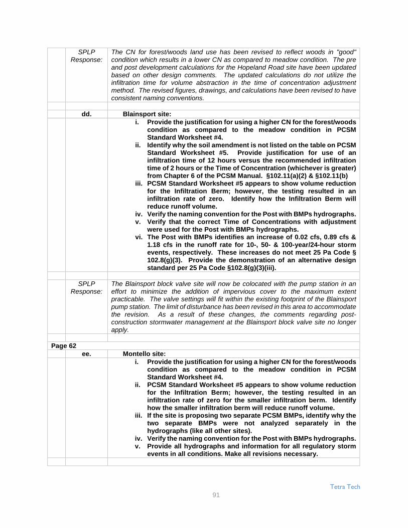
Tetra Tech
91
SPLPResponse:
The CN for forest/woods land use has been revised to reflect woods in "good"condition which results in a lower CN as compared to meadow condition. The preand post development calculations for the Hopeland Road site have been updatedbased on other design comments. The updated calculations do not utilize theinfiltration time for volume abstraction in the time of concentration adjustmentmethod. The revised figures, drawings, and calculations have been revised to haveconsistent naming conventions.
dd. Blainsport site:i. Provide the justification for using a higher CN for the forest/woods
condition as compared to the meadow condition in PCSMStandard Worksheet #4.
ii. Identify why the soil amendment is not listed on the table on PCSMStandard Worksheet #5. Provide justification for use of aninfiltration time of 12 hours versus the recommended infiltrationtime of 2 hours or the Time of Concentration (whichever is greater)from Chapter 6 of the PCSM Manual. §102.11(a)(2) & §102.11(b)
iii. PCSM Standard Worksheet #5 appears to show volume reductionfor the Infiltration Berm; however, the testing resulted in aninfiltration rate of zero. Identify how the Infiltration Berm willreduce runoff volume.
iv. Verify the naming convention for the Post with BMPs hydrographs.v. Verify that the correct Time of Concentrations with adjustment
were used for the Post with BMPs hydrographs.vi. The Post with BMPs identifies an increase of 0.02 cfs, 0.89 cfs &
1.18 cfs in the runoff rate for 10-, 50- & 100-year/24-hour stormevents, respectively. These increases do not meet 25 Pa Code §102.8(g)(3). Provide the demonstration of an alternative designstandard per 25 Pa Code §102.8(g)(3)(iii).
SPLPResponse:
The Blainsport block valve site will now be colocated with the pump station in aneffort to minimize the addition of impervious cover to the maximum extentpracticable. The valve settings will fit within the existing footprint of the Blainsportpump station. The limit of disturbance has been revised in this area to accommodatethe revision. As a result of these changes, the comments regarding post-construction stormwater management at the Blainsport block valve site no longerapply.
Page 62ee. Montello site:
i. Provide the justification for using a higher CN for the forest/woodscondition as compared to the meadow condition in PCSMStandard Worksheet #4.
ii. PCSM Standard Worksheet #5 appears to show volume reductionfor the Infiltration Berm; however, the testing resulted in aninfiltration rate of zero for the smaller infiltration berm. Identifyhow the smaller infiltration berm will reduce runoff volume.
iii. If the site is proposing two separate PCSM BMPs, identify why thetwo separate BMPs were not analyzed separately in thehydrographs (like all other sites).
iv. Verify the naming convention for the Post with BMPs hydrographs.v. Provide all hydrographs and information for all regulatory storm
events in all conditions. Make all revisions necessary.

Tetra Tech
92
SPLPResponse:
The CN for forest/woods land use has been revised to reflect woods in "good"condition which results in a lower CN as compared to meadow condition. The preand post development calculations for the Montello Road site have been updatedbased on other design comments and additional infiltration testing has taken place.An infiltration berm is no longer proposed in the area of the area of zero infiltration.The separate PCSM BMPs have been modeled separately and are no longercombined. The naming convention has been updated to be consistent for allhydrograph outputs. All hydrographs and information for all regulatory storm eventshave been provided.
ff. Wyomissing site:i. Provide the justification for using a higher CN for the
forest/woods condition as compared to the meadow conditionin PCSM Standard Worksheet #4.
ii. PCSM Standard Worksheet #5 appears to show volumereduction for the Infiltration Berm; however, the testingresulted in an infiltration rate of zero for the smaller infiltrationberm. Identify how the smaller infiltration berm will reducerunoff volume.
iii. If the site is proposing two separate PCSM BMPs, identify whythe two separate BMPs were not analyzed separately in thehydrographs (like all other sites).
iv. Verify the naming convention for the Post with BMPshydrographs.
v. Provide all hydrographs and information for all regulatorystorm events in all conditions. Make all revisions necessary.
SPLPResponse:
The referenced block valve site is no longer proposed as an impervious surface.Due to various site constraints, it was not feasible to accommodate stormwatermanagement BMPs within the project area. The access road and block valve willbe graded as shown on the plan, and geoweb will provide structural support andmaintain void space. The geoweb will be filled with soil and vegetated to a meadowin good condition, thereby eliminating the necessity to perform stormwatermanagement calculations.
Page 6333. DEP The following technical deficiencies are associated with Attachment 5: 25 Pa
Code §102.8(g)(1)a. Table 1 only provides for 18 site locations, and there are an additional 7
site locations provide in the table after the certification. Clarify the numberof site locations versus the identified number of site locations throughoutthe narrative.
SPLPResponse:
Table 1 summarizes 18 sites along Construction Spreads 3, 4, 5 and 6 where workwas completed by Tetra Tech NUS of Pittsburgh, PA and certified by Tim S. Evanson May 26, 2016. An additional 17 sites along the same Construction Spreads wascompleted by Tetra Tech EMI of Newark, DE and certified by Ralph Boedeker onMay 26, 2016. Table 1 will be updated based on work performed in Fall 2016 andrecommended infiltration rates will reflect appropriate results from both 2015 and2016 infiltration testing.
b. There appear to be at least three sites identified on Table 1 for which noinfiltration testing was performed at the site or at the BMP. The provideddiscussion is not an adequate demonstration of appropriate infiltrationand geologic studies. Provide the demonstration that the predevelopmentsite characterization and assessment of soil and geology is adequate.

Tetra Tech
93
SPLPResponse:
Based on Table 1 and the additional table, infiltration testing was performed at allsites. Infiltration testing results were determined to be invalid at the Creek Road siteand therefore, no recommended rate was provided. As observed in these tables,some infiltration tests performed were outside of BMP areas and were therefore notconsidered in the Sites recommended rate. Detailed discussions pertaining toinfiltration testing and geological conditions of the sites are provided in the TripReports for each site. Based on these reports, the predevelopment sitecharacterization and assessment of soil and geology is adequate.
c. Identify why some Soil Types are identified as "N/A" in Table 1.
SPLPResponse:
The following summarizes the rationale for using "NA" for Soil Type in Table 1 - 1)For Creek Road, there was no soil, only rock; 2) For Middlesex Road, test pittingwas completed at IT-1, IT-2 and IT-3 and given close proximity to IT-4 and IT-5, soilswere assumed to be consistent; 3) For Valley Forge Road, NA at IT-02 should beSilt Loam as in IT-01 based on the Boring Log completed July 14, 2015; 4) For GlennMills, two representative borings were completed (IT-3 and between IT-2 and IT-4)for the site and based on consistent soils and proximity to IT-1, IT-5 and IT-6, SiltLoam can be applied to these locations as well (though these locations are outsideof the BMP area and recommendations are not completed).
d. Identify how the Safety Factor was determined for use in Table 1. If theutilized Safety Factor is not within the recommendations of Appendix C ofthe PCSM Manual; then provide an adequate demonstration of analternative BMP and design standard. 25 Pa Code §102.8(f)(8),§102.11(a)(2) & §102.11(b)
SPLPResponse:
Determination of the Safety Factor is provided in the Notes (page 3 of 3) where aFS of 2 is assumed for soils coarser than loam and a FS of 3 is assumed for finergrained soils. Both FS are in accordance with Appendix C of the PCSM Manual andwithin the recommended ranges of 2 to 10.
e. On Table 1 for Schaeffer Road, testing IT-01 through 04 & 06 wereidentified. Identify if a test location of IT-05 was performed. If so, providethose testing results. Provide the detailed information for IT-06.
SPLPResponse:
Based on the Trip Report for Schaeffer Road, IT-06 is a typographical error. Itshould be IT-05.
f. The table provided after the certification appears to include sites locatedoutside of the South-central Region. Revise the table to only include sitesthat are covered by the ESCGP-02 Permit application.
SPLPResponse:
Table 1 is being revised based on infiltration testing performed in Fall of 2015 and2016. Only sites present within the ESCGP-02 permit will be included.
Page 64g. Table 1 identifies that tests IT-01 & 02 are with or near the BMP; however,
the PCSM Plan drawings identify the testing outside of the BMP. Clarifythis discrepancy.

Tetra Tech
94
SPLPResponse:
There are numerous infiltration tests that are noted to be either within or near(outside) the BMP areas. Only infiltration tests from 2015 and 2016 within the BMPor 25 feet of the BMP will be utilized to determine an appropriate recommended ratein the updated Table 1.
h. Provide additional information related to the elevations of the identifiedlimiting zones (e.g. bedrock, weathered bedrock, groundwater, regularlyoccurring seasonally high water table, etc.).
SPLPResponse:
Based on the comment, it is unclear which site (or sites) the comment refers to.Generally, the information cited in the comment are provided in the Trip Reports.
i. There appear to be numerous sites which propose to infiltrate stormwaterwith less than a 2-ft. separation from a limiting zone (e.g. bedrock,weathered bedrock, groundwater, regularly occurring seasonally highwater table, etc.) or the Soil Logs ended before 2-ft. below the proposedinfiltration elevation. Provide discussion as to how the stormwater isbeing infiltrated properly. If the 2-ft. separation is not provided, thenprovide the alternative BMP and design standard demonstration. 25 PaCode §91.51(a), §102.8(f)(15), §102.11(a)(2) & §102.11(b)
SPLPResponse:
As with the previous comment, it is unclear which site (or sites) the comments refersto. Details pertaining to whether bedrock (or weathered bedrock), mottling, andgroundwater/seasonal high groundwater were encountered are provided in the TripReports. Additionally, if conditions prevented attaining these details, explanationsand appropriate interpretations are provided. As noted in previous responses, Table1 is being revised based on infiltration testing performed in the Fall of 2015 and2016.
j. Provide more appropriate soil color descriptions (e.g. from the MunsellSoil Color Charts).
SPLPResponse:
The soil color descriptions provided as part of the infiltration testing are standardrepresentations of the methodology used by the professional geologists overseeingthe tests. The Munsell Soil color does not add further value to the infiltration ratedetermined at the test site. However, Munsell Soil colors will be utilized duringinfiltration testing performed in the Fall 2016 field work. Additionally, if no newinfiltration tests will be performed at previously tested sites in Fall 2016, Munsell Soilcolors only will be obtained from previously tested sites (Fall 2015).
k. There appear to be numerous locations where two infiltration tests wereperformed, but only one soil log was recorded. Provide a discussion asto why this is appropriate and also provide an adequate predevelopmentsite characterization and assessment of soil and geology.
SPLPResponse:
At many sites where at least two infiltration tests were performed, infiltration testinglocations were approximately 50 feet or less from each other and occurred in thesame topographical setting/feature. When this occurred, a single soil boring (or testpit) was completed to represent the typical conditions that occur within this area.Overall, a soil boring (or test pit) was completed in each unique topographical settingwhere infiltration testing occurred to ensure that the subsurface was adequatelycharacterized.
For each site where soil borings or test pits represented more than one infiltrationtest, the text will be edited to clarify the representative nature of the soil boringscollected.

Tetra Tech
95
l. Valley Forge site: Provide the location of the July 12, 2015 auger.
SPLPResponse:
Coordinates are provided on the Test Boring Log (page 10 of 23) in trip report, whichare 40° 24' 16.45"N, 78° 29' 37.94"W. The location will added to the site map (nearIT-2). The Trip Report has been updated.
m. Locke Mountain Road site: Clearly identify if any redoximorphic (redox.)features were observed in the Soil Log.
SPLPResponse:
The following sentence was added in Section 3.1 to clarify that no mottling(redoximorphic) features were observed - "Additionally, no mottling (redoximorphic)was observed at either location." The Trip Report has been updated.
n. Juniata River West site: Provide additional discussion related to theidentified redoximorphic (redox.) features, and what the relationship is tothe top and bottom being dry.
SPLPResponse:
Based on the soil log, clays were more prevalent between 12 and 18 inches, wheremottling was potentially noted. It is likely that water/moisture is retained (or trapped)in this zone due to the less permeable clays present as compared to the soil aboveand below, which contain sands and silts which more effectively drain (or transport)water/moisture. Section 3.1 will be updated to reflect this observation andinterpretation. The Trip Report has been updated.
o. Juniata River East site:i. Clearly identify if groundwater was/was not encountered during
the assessment of soil and geology.ii. It does not appear that IT-2 reached a stabilized rate or that eight
consecutive readings were taken; provide discussion as to why astabilize rate or eight consecutive readings were not recorded.Identify how the "Average Stabilized Rate" was determined. 25 PaCode §102.11(a)(2) & §102.11(b)
SPLPResponse:
The text and soil boring will be updated to clarify that groundwater was notencountered. While it does not appear that IT-2 reached stabilization, nineconsecutive readings were collected at 10-minute intervals between 1220 and 1350,one more than the required minimum of eight readings. The Average StabilizedRate was determined from an average of the final four readings and standardizedinto an hourly rate.
Page 65p. Raystown Lake West site:
i. Section 3.1 discusses assuming a weathered rock elevation.Provide additional information as to how the weathered rockelevation was assumed (i.e. what information was evaluated toreach the determination) and identify how this is an adequate andappropriate predevelopment site characterization and assessmentof soil and geology.
ii. Identify where the Boring Log and Soil Log were taken, as itappears that tests IT-01 & 02 were far apart from each other.

Tetra Tech
96
SPLPResponse:
Based on the frequency and size of rock fragments observed from 30 to 37 inchesbelow ground surface, it was assumed that this was indicative of weathered rock.This cannot be confirmed due to the boring method (hand auger). Section 3.1 textwill be updated to reflect this evaluation. The boring log/soil log was completed at alocation approximately mid-way between IT-01 and IT-02 since site conditions weresimilar at both locations (along and within wooded area with minor underbrush).Section 2.0 text was updated to reflect in installation of a single boring/augerlocation.
q. Happy Hills site:Clarify why there are Site Geology Maps provided for Site 1 and Site 2.
SPLPResponse:
Two geologic maps are provided since the site is located along a boundary betweentwo geologic units - the Pocono or Maunch Chunk Formations. Section 3.1 statesthat the site may lie in either of these formations, therefore, no changes to the textare required.
r. PA 655 site: Identify what the second Boring Log and Soil Log are for.
SPLPResponse:
As summarized in Section 2, one hand auger location was completed near the mid-point between IT-1 and IT-2 and another near IT-3 (since IT-3 was located > 50 feetfrom IT-1 and IT-2). No changes to the text are required.
s. Shade Valley Highway site: Clarify why there are Site Geology Mapsprovided for Site 1 and Site 2.
SPLPResponse:
Two geologic maps are provided since the site is located along a boundary betweentwo geologic units - the Keyser through Mifflintown Formations or the Onondage andOld Port Formations. Section 3.1 states that the site may lie in either of theseformations, therefore, no changes to the text are required.
t. Creek Road site:iii. Section 2.0 identified that the testing was performed in accordance
with the recommendations of the PCSM Manual. Protocol 1, Step3.b in Appendix C of the PCSM Manual identified that the preparedhole should have a uniformed diameter of 6 to 10 inches; however,IT #1 identifies the hole being a conical oblong with a maximumwidth of 20 inches and IT #2 identified the hole being conical witha varying diameter of 8-12 inches. Because the testing was notdone in accordance with the recommendations of the PCSMManual, provide the demonstration of alternative BMP and designstandard. 25 Pa Code §102.11(a)(2) & §102.11(b)
iv. Provide the Reduction Factor calculations. 25 Pa Code §102.8(f)(8)
SPLPResponse:
Comment acknowledged. The material at the site at the ground surface was fissileshale which fractured in an uncontrollable manner. While it is unlikely that the slightoblong nature of the percolation holes would significantly impact the infiltrationresults, it is acknowledged that the percolation holes are not uniform in diameter.Infiltration testing will be performed in 2016 and modifications based on these resultswill be utilized to design the appropriate BMP structure. The infiltration data providedin the 2015 Trip Report will not be used in the BMP design. As such, the ReductionFactor calculations are not provided (the formula is presented in Appendix C of thePCSM Manual - Page 9 - and input data is provided in the Infiltration Test DataSheets of the 2015 Trip Report).

Tetra Tech
97
u. Wolf Bridge Road A & B site:i. Identify why there are only three Soil Logs for four infiltration test
locations. Identify why one Soil Log is for IT #1 and another SoilLog is for IT #1/3.
ii. Oxidation in the shale is identified. Provide discussion as to whatthe oxidation is from.
iii. It appears that weathered rock is not being identified as a limitingzone. Provide discussion as to why weathered rock was notincluded in the recommended 2 ft. separation between infiltrationand rock.
SPLPResponse:
Due to the uniform topography and surface conditions across the site, initially, oneboring was completed mid-point between IT-1 and IT-3 and another boring at themid-point of IT-2 and IT-4. Based on the different response observed in theInfiltration test at IT-1 compared to the other locations, a third boring was performednear IT-1 to further evaluate specific soil conditions. Section 3.1 will be updated toreflect that the oxidation that occurred on the shale was in the form of iron oxidation(rust) based on the dark reddish staining observed. It is assumed that the weatheredrock would not inhibit infiltration of water since the boring and soil logs show that itwas easily broken and exhibited evidence of weathering (iron oxidation). Based onall of the presence of shallow bedrock, it unlikely that a BMP infiltration design willbe employed at this site.
Page 66v. Middletown Junction Valves 1 & 2 site:i. Provide additional discussion as to why the single-ring falling head
infiltration test is an appropriate testing methodology for this site.This type of testing methodology is not identified as a recommendedtest in Protocol 1, Step 3 of Appendix C of the PCSM Manual. 25 PaCode §102.11(a)(2) & §102.11(b)
SPLPResponse:
Appendix C of the PCSM Manual does not dictate methods to be used, but providesexample Methodologies and further discusses the double-ring methodology. TheManual also lists other testing methods and standards and indicates that list is “notlimited to”. The single-ring falling head test is ASTM approved (ASTM D5126) andis commonly used in determination of infiltration rates.
ii. Provide the information from and the location of the StandardPenetration Test.
SPLPResponse:
As indicated in the report, the intended method for infiltration testing was the double-ring constant head test; however, the field water truck used to supply water fortesting could not access test locations within reasonable water hauling distance.Therefore, the method used to conduct infiltration testing was the single-ring fallinghead test. This commonly accepted test method utilizes a considerable amount lesswater, and the water was reasonably hauled to the test locations with buckets.
iii. Identify what the underlying geology is for the site.
SPLPResponse:
As indicated in the fourth paragraph of the report, the site is underlain by theGettysburg Formation. The location of the Standard Penetration Test isapproximately 130 feet northeast of the infiltration test locations and did notencounter bedrock to 25 feet below ground surface. Figure 1 has been updated inthe Trip Report to show the location of the boring and the boring log has beenprovided in Attachment 2.

Tetra Tech
98
w. Gates Road site:i. Provide additional discussion as to why the double-ring constant head
infiltration test in an appropriate testing methodology for this site.This type of testing methodology is not identified as a recommendedtest in Protocol 1, Step3 of Appendix C of the PCSM Manual. 25 PaCode §102.11(a)(2) & §102.11(b)
SPLPResponse:
Appendix C of the PCSM Manual does not dictate methods to be used, but providesexample Methodologies and further discusses the double-ring methodology. TheManual also lists other testing methods and standards and indicates that list is “notlimited to”. The double-ring constant head test is ASTM approved (ASTM D3385)and is commonly used in determination of infiltration rates.
ii. For IT-01, 17 of the 20 trials identified zero movement for the inner ring.Provide discussion as to how infiltration is adequate and appropriatefor this site. Identify how the average rate of 0.1012 in./hr. wasdetermined, as the inner ring average appears to be 0.0805 in./hr.§102.8(f)(8)
SPLPResponse:
For IT-01 and IT-02, the average rate summarized in Table 1 (represented to twosignificant figures) was determined by taking the average of the second, third, fourthand fifth hourly averages from the test data. Based on the locations of the InfiltrationTests with respect to the proposed BMP, an appropriate recommended value isprovided, which includes incorporation of a Factor of Safety.
iii. For IT-02, identify how the average rate of 1.6862 in./hr. wasdetermined. 25 Pa Code §102.8(f)(8)
SPLPResponse:
For IT-01 and IT-02, the average rate summarized in Table 1 (represented to twosignificant figures) was determined by taking the average of the second, third, fourthand fifth hourly averages from the test data. Based on the locations of the InfiltrationTests with respect to the proposed BMP, an appropriate recommended value isprovided, which includes incorporation of a Factor of Safety.
iv. Identify what the underlying geology is for the site.
SPLPResponse:
The underlying geology is the Hammer Creek Formation, a reddish-brown Triassiccoarse-grained sandstone with interbed of red shale and quartz-pebbleconglomerates. The following text has been inserted after the third sentence of thethird paragraph on page 1 of the 2015 Trip Report, "The underlying geology is theamber Creek Formation, a reddish-brown Triassic coarse-grained sandstone withinterbed of red shale and quartz-pebble conglomerates."
x. Schaeffer Road/Obie Road site: The Schaeffer Road #5 summary does notmatch the Infiltration Test Data Sheet; the drop time at 1430 is reporteddifferently. Clearly identify if a stabilized rate or that eight consecutivereadings were taken.
SPLPResponse:
The summary sheet for Schaeffer Road IT-5 is incorrect for the 1430 time. Asobserved in the Infiltration Test Data Sheet, the drop should have been 1.5 inches,not 1.0 inches. This correction has been made to the sheet and updated in the 2015Trip Report. Based on this corrected value, stabilization has been reached inaccordance with Appendix C of the PCSM Manual.

Tetra Tech
99
y. Schaefferstown Tie In site:i. Provide additional discussion as to why the double-ring constant head
infiltration test is an appropriate testing methodology for this site.This type of testing methodology is not identified as a recommendedtest in Protocol 1, Step 3 of Appendix C of the PCSM Manual. 25 PaCode §102.11(a)(2) & §102.11(b)
SPLPResponse:
Appendix C of the PCSM Manual does not dictate methods to be used, but providesexample Methodologies and further discusses the double-ring methodology. TheManual also lists other testing methods and standards and indicates that list is “notlimited to”. The double-ring constant head test is ASTM approved (ASTM D3385)and is commonly used in determination of infiltration rates.
Page 67ii. Identify what the underlying geology is for the site.
SPLPResponse:
The underlying geology is the undifferentiated Limestone fanglomerate, Triassiclimestone and dolomite pebbles and fragments in a red, very fine grained quartzmatrix. The following text has been inserted after the third sentence of the thirdparagraph on page 1 of the 2015 Trip Report, "The underlying geology is the anundifferentiated Limestone fanglomerate, Triassic limestone and dolomite pebblesand fragments in a red, very fine grained quartz matrix"
z. Hopeland Road site:i. Provide additional discussion as to why the double-ring constant head
infiltration test is an appropriate testing methodology for this site.This type of testing methodology is not identified as a recommendedtest in Protocol 1, Step 3 of Appendix C of the PCSM Manual. 25 PaCode §102.11(a)(2) & §102.11(b)
SPLPResponse:
Appendix C of the PCSM Manual does not dictate methods to be used, but providesexample Methodologies and further discusses the double-ring methodology. TheManual also lists other testing methods and standards and indicates that list is “notlimited to”. The double-ring constant head test is ASTM approved (ASTM D3385)and is commonly used in determination of infiltration rates.
ii. For IT-01, 17 of the 20 trials identified zero movement for the inner ring.Provide discussion as to how infiltration is adequate and appropriatefor this site.
SPLPResponse:
For IT-02 (where 17 of the 20 readings identify zero movement), the average ratesummarized in Table 1 (represented to two significant figures) was determined bytaking the average of the second, third, fourth and fifth hourly averages from the testdata. Based on the locations of the Infiltration Tests with respect to the proposedBMP, an appropriate recommended value is provided, which includes incorporationof a Factor of Safety.
iii. Identify what the underlying geology is for the site.
SPLPResponse:
The underlying geology is the Hammer Creek conglomerate, a very coarse quartzconglomerate with abundant pebbles and cobbles of gray quartzite. The followingtext has been inserted after the third sentence of the third paragraph on page 1 ofthe 2015 Trip Report, "The underlying geology is the Hammer Creek conglomerate,a very coarse quartz conglomerate with abundant pebbles and cobbles of grayquartzite."

Tetra Tech
100
aa. Blainsport site:i. Provide additional discussion as to why the single-ring falling head
infiltration test is an appropriate testing methodology for this site.This type of testing methodology is not identified as a recommendedtest in Protocol 1, Step 3 of Appendix C of the PCSM Manual. 25 PaCode §102.11(a)(2) & §102.11(b)
SPLPResponse:
Appendix C of the PCSM Manual does not dictate methods to be used, but providesexample Methodologies and further discusses the double-ring methodology. TheManual also lists other testing methods and standards and indicates that list is “notlimited to”. The single-ring falling head test is ASTM approved (ASTM D5126) andis commonly used in determination of infiltration rates.
ii. Provide the information from and the location of the StandardPenetration Test.
SPLPResponse:
As indicated in the report, the intended method for infiltration testing was the double-ring constant head test; however, the field water truck used to supply water fortesting could not access test locations within reasonable distance because of steepgrades and fencing along the access route around the existing Blainsport Station.Therefore, the method used to conduct infiltration testing was the single-ring fallinghead test. This commonly accepted test method utilizes a considerable amount lesswater, and the water was reasonably hauled to the test locations with buckets.
The Standard Penetration Tests did not encounter bedrock to 20 or 25 feet belowground surface. Figure 1 has been updated in the Trip Report to show the locationsof the borings and the boring logs have been provided in Attachment 2.
iii. Identify what the underlying geology is for the site.
SPLPResponse:
The underlying geology is the Hammer Creek Formation, a reddish-brown Triassiccoarse-grained sandstone with interbed of red shale and quartz-pebbleconglomerates. The following text has been inserted after the sixth sentence of thethird paragraph on page 1 of the 2015 Trip Report, "The underlying geology is theHammer Creek Formation, a reddish-brown Triassic coarse-grained sandstone withinterbed of red shale and quartz-pebble conglomerates."
bb. Montello site:i. Provide additional discussion as to why the single-ring falling head
infiltration test is an appropriate testing methodology for this she.This type of testing methodology is not identified as a recommendedtest in Protocol 1, Step 3 of Appendix C of the PCSM Manual. 25 PaCode §102.11(a)(2) & §102.11(b)
SPLPResponse:
Appendix C of the PCSM Manual does not dictate methods to be used, but providesexample Methodologies and further discusses the double-ring methodology. TheManual also lists other testing methods and standards and indicates that list is “notlimited to”. The single-ring falling head test is ASTM approved (ASTM D5126) andis commonly used in determination of infiltration rates.
ii. Table 1 identifies the test depth for IT-05 as 0.5 in.; however the DoubleRing Infiltration Test results identify a test depth of 0.5 ft. Clarify thisdiscrepancy.

Tetra Tech
101
SPLPResponse:
As discussed in the report, the intended method for infiltration testing was thedouble-ring constant head test, and was performed at three of the five test locations(IT-03, IT-04, and IT-05). At two of the locations (IT-01, IT-02), the field water truckused to supply water for testing could not access test locations within reasonabledistance because of their locations within a corn field (water truck would havedestroyed crop along access route). Therefore, the method used to conductinfiltration testing at IT-01 and IT-02 was the single-ring falling head test. Thiscommonly accepted test method utilizes a considerable amount less water, and thewater was reasonably hauled to the test locations with buckets.
iii. For IT-04, 14 of the 20 trials identified zero movement for the inner ring.Provide discussion as to how infiltration is adequate and appropriatefor this site.
SPLPResponse:
IT-05 was performed at 0.5 feet. Table 1 has been updated to reflect this change.For IT-04 and IT-05, the average rate summarized in Table 1 (represented to twosignificant figures) was determined by taking the average of the second, third, fourthand fifth hourly averages from the test data. Based on the locations of the infiltrationTests with respect to the proposed BMP, an appropriate recommended value isprovided, which includes incorporation of a Factor of Safety.
Page 68iv. For IT-05, 19 of the 20 trials identified zero movement for the inner ring.
Provide discussion as to how infiltration is adequate and appropriatefor this site.
SPLPResponse:
IT-05 was performed at 0.5 feet. Table 1 has been updated to reflect this change.For IT-04 and IT-05, the average rate summarized in Table 1 (represented to twosignificant figures) was determined by taking the average of the second, third, fourthand fifth hourly averages from the test data. Based on the locations of the InfiltrationTests with respect to the proposed BMP, an appropriate recommended value isprovided, which includes incorporation of a Factor of Safety.
v. Identify, what the underlying geology is for the site.
SPLPResponse:
The underlying geology is the Millbach Formation, a pinkish gray and medium grayCambrian laminated limestone with interbeds of dolomite. The following text hasbeen inserted after the third sentence of the third paragraph on page 1 of the 2015Trip Report, "The underlying geology is the Millbach Formation, a pinkish gray andmedium gray Cambrian laminated limestone with interbeds of dolomite."
cc. Wyomissing site:i. Provide additional discussion as to why the single-ring falling head
infiltration test is an appropriate testing methodology for this site.This type of testing methodology is not identified as a recommendedtest in Protocol 1, Step 3 of Appendix C of the PCSM Manual. 25 PaCode §102.11(a)(2) & §102.11(b)
SPLPResponse:
Appendix C of the PCSM Manual does not dictate methods to be used, but providesexample Methodologies and further discusses the double-ring methodology. TheManual also lists other testing methods and standards and indicates that list is “notlimited to”. The single-ring falling head test is ASTM approved (ASTM D5126) andis commonly used in determination of infiltration rates.
ii. Identify what the underlying geology is for the site.

Tetra Tech
102
SPLPResponse:
The underlying geology is the Hammer Creek conglomerate, a very coarse quartzconglomerate with abundant pebbles and cobbles of gray quartzite. The followingtext has been inserted after the third sentence of the third paragraph on page 1 ofthe 2015 Trip Report, "The underlying geology is the Hammer Creek conglomerate,a very coarse quartz conglomerate with abundant pebbles and cobbles of grayquartzite."
34. DEP DEP recommends only providing one copy of the plan drawings perapplication set (do not provide reduced scale drawings in Attachment 6), toavoid confusion and potential inconsistencies. 25 Pa Code §102.8(f)(9)
SPLPResponse:
Comment acknowledged.
PCSM Narrative Mount Union Valves1. Section 1.0 on Page 1 identifies that this Post Construction Stormwater
Management (PCSM) Plan is incorporated in the project's Erosion andSediment Control (E&S) Plan. The PCSM Plan shall be separate from the E&SPlan and the E&S Plan shall be separate from the PCSM Plan. 25 Pa Code§102.4(b)(5)(xiv) & §102.8(d)
SPLPResponse:
The referenced sentence was removed.
2. Section 2.0 on Page 2 does not include discussion related to any proposedPCSM best management practices (BMPs). Ensure that the Site Descriptionproperly identifies and includes the PCSM BMPs. 25 Pa Code §102.8(f)(3) &§102.8(f)(6)
SPLPResponse:
The PCSM BMPs are described in section 4.0 of the report. For clarification, thetitle of section 2.0 was revised to “Existing Site Description” and Section 1.0 wasupdated to clarify what is discussed in each section.
3. Section 2.2 on Page 3 provides for resolution if high groundwater isencountered; however, the resolution is only related to during earthdisturbance activities. Provide appropriate resolution for this soil limitationfor the post construction condition and how the project was designed toaddress the limitation for the PCSM BMPs. 25 Pa Code §102.8(f)(12) &§102.8(g)(5)
SPLPResponse:
The following paragraph was added to section 4.4 of the PCSM report:“Groundwater was not encountered in the test pits that were dug during infiltrationtesting. If groundwater is encountered during construction of the BMP, the certifyingengineer should be consulted to determine what measures, if any, need to be takento ensure that groundwater will not interfere with proper functioning of the BMP.”
4. Section 2.3 on Page 4 identifies "This E&SC plan..." This is the narrative forthe PCSM Plan for the Mount Union Valves site. The PCSM Plan shall beseparate from the E&S Plan and the E&S Plan shall be separate from the PCSMPlan. Make all revisions necessary. 25 Pa Code §102.4(b)(5)(xiv) & §102.8(d)
SPLPResponse:
The reference was changed from E&SC to PCSM.

Tetra Tech
103
Page 695. The following technical deficiencies are associated with Section 3.1 starting
on Page 5: 25 Pa Code § 102.8(f)(7)a. The first sentence identifies to reference the E&S plan drawings for the
PCSM BMPs. This does not meet regulation. The PCSM Plan is thedocument to reference for the PCSM BMPs. Make all revisions necessary.
SPLPResponse:
The PCSM plan has been revised to reference the correct PCSM BMPs.
b. It is identified that "It is not intended that the drawings and this reportshow detailed information on methods and materials." This statementdoes not meet regulations. The E&S and PCSM Plans shall be final forconstruction, and the information, details and provide methods andmaterials to properly construct and implement the Plans, including theBMPs, as part of the construction sequences associated with these Plans.25 Pa Code §102.4(b)(5)(xiv) & §102.8(d)
SPLPResponse:
The statement quoted was in reference to "methods and materials" needed for theconstruction of the structural equipment on site and not the PCSM BMPs. Toeliminate confusion, the statement has been removed.
c. The narrative identifies that the contractor can deviate from the authorizedE&S and PCSM Plans based upon field conditions. A deviation from theauthorized plans may be necessary; however, the appropriate countyconservation district and DEP have to approve any deviation to theauthorized plans. Make all revisions necessary to clearly identify thisrequirement.
SPLPResponse:
Section 3.1 of the PCSM has been updated to state that any deviation from theproposed PCSM plan shall be approved by the county conservation district and theDEP before any action commences.
d. Provide a schedule of inspections for critical stages of PCSM BMPinstallation with the construction sequence.
SPLPResponse:
Section 3.8 of the PCSM narrative has been updated to include a schedule ofinspections, and Section 3.1 of the PCSM narrative has been updated to referencewhich critical stages a licensed professional shall oversee.
e. The specific construction sequence for the infiltration filter appears to bewritten for more of an actual constructed filter with a soil mixture, asopposed to the designed and detailed BMP of an infiltration trench.Ensure that the type of PCSM BMP is properly identified, and ensure thatthe construction sequence is written for the BMP that is designed.
SPLPResponse:
The construction sequence for the infiltration filter has been updated to reflect theinstallation of the correct PCSM BMP.
f. Step 2 references reinforced concrete boxes; however, the PCSM Plandoes not appear to identify concrete boxes as part of the design. Ensurethat the construction sequence is written for the BMP that is designed.

Tetra Tech
104
SPLPResponse:
The infiltration filter installation sequence has been updated to reflect the installationof the correct PCSM BMP.
g. More information is required in Step 3 related to how to properly excavatefor the infiltration trench. Identify how the trench will be constructed (Willthe trench be excavated from the sides? If not, how will the heavyequipment be used so that the underlying soil is not compacted? Etc.).Identify how the contractor will lightly compact the stone withoutcompacting the underlying soil.
SPLPResponse:
The sequence in section 3.1 for the underground storage pipes was revised toindicate that heavy equipment shall not enter the trench and that stone will be spreadand self-compacted under its own weight instead of compaction with equipment.
h. Steps 3 & 4 are confusing, as these seem to be more design relatedcomponents of the BMP and not part of the construction sequence. Step4 identifies that infiltration filter to be underlain by a layer of permeablenon-woven-geotextile; if the design is to have a geotextile fabric, in theconstruction sequence clearly identify that the geotextile fabric is to beplaced. Make all revisions necessary.
SPLPResponse:
Steps 3 & 4 in Section 3.1 have been updated to clearly state the steps that will betaken when installing the infiltration trench.
Page 70i. Step 5 identifies to place the underlying stone in minimum 6 inch lifts;
however, the details on the plan drawings identify the underlying stonedepth as 6 in. Ensure that the construction sequence is written for theBMP that is designed.
SPLPResponse:
The word "underlying" was removed to indicate that all gravel shall be placed in 6inch lifts.
j. Step 10 appears to be more design related than construction related.Revise this step as necessary so that this step is more related to theconstruction sequence of the BMP.
SPLPResponse:
Step 10 has been removed as it does not apply to the construction of the designedinfiltration filter.
6. Section 3.5 on Page 11 is not sufficient as it does not provide for procedureswhich ensure that the proper measures for recycling or disposal of materialsassociated with or from the PCSM BMPs are in accordance with Departmentlaws, regulations and requirements. 25 Pa Code §102.8(f)(11)
SPLPResponse:
Section 3.5 in the PCSM narrative states that the "operator will remove from the site,recycle, or dispose of all building materials and wastes in accordance with PADEP’ssolid waste management regulations at 25 PA Code 260.1 et seq., 271.1 et seq.,and 287.1 et seq". The following additional waste management procedures wereadded to the narrative in section 3.5: “The operator will first characterize the wastematerials as municipal, residual or hazardous waste. Before the waste material ishauled away, the material will be stored and labeled in accordance with theapplicable management procedures, if any, under the Solid Waste Management Actregulations. The operator will then hire a licensed and insured waste hauler totransport the waste material to a properly permitted waste disposal facility.”
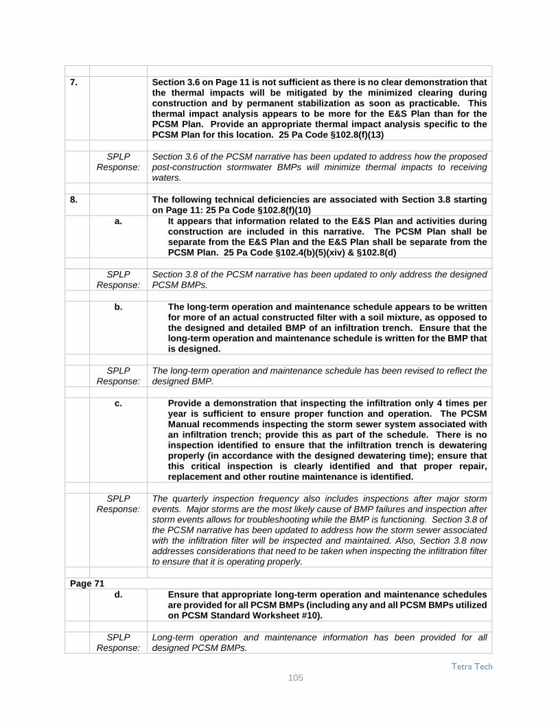
Tetra Tech
105
7. Section 3.6 on Page 11 is not sufficient as there is no clear demonstration thatthe thermal impacts will be mitigated by the minimized clearing duringconstruction and by permanent stabilization as soon as practicable. Thisthermal impact analysis appears to be more for the E&S Plan than for thePCSM Plan. Provide an appropriate thermal impact analysis specific to thePCSM Plan for this location. 25 Pa Code §102.8(f)(13)
SPLPResponse:
Section 3.6 of the PCSM narrative has been updated to address how the proposedpost-construction stormwater BMPs will minimize thermal impacts to receivingwaters.
8. The following technical deficiencies are associated with Section 3.8 startingon Page 11: 25 Pa Code §102.8(f)(10)
a. It appears that information related to the E&S Plan and activities duringconstruction are included in this narrative. The PCSM Plan shall beseparate from the E&S Plan and the E&S Plan shall be separate from thePCSM Plan. 25 Pa Code §102.4(b)(5)(xiv) & §102.8(d)
SPLPResponse:
Section 3.8 of the PCSM narrative has been updated to only address the designedPCSM BMPs.
b. The long-term operation and maintenance schedule appears to be writtenfor more of an actual constructed filter with a soil mixture, as opposed tothe designed and detailed BMP of an infiltration trench. Ensure that thelong-term operation and maintenance schedule is written for the BMP thatis designed.
SPLPResponse:
The long-term operation and maintenance schedule has been revised to reflect thedesigned BMP.
c. Provide a demonstration that inspecting the infiltration only 4 times peryear is sufficient to ensure proper function and operation. The PCSMManual recommends inspecting the storm sewer system associated withan infiltration trench; provide this as part of the schedule. There is noinspection identified to ensure that the infiltration trench is dewateringproperly (in accordance with the designed dewatering time); ensure thatthis critical inspection is clearly identified and that proper repair,replacement and other routine maintenance is identified.
SPLPResponse:
The quarterly inspection frequency also includes inspections after major stormevents. Major storms are the most likely cause of BMP failures and inspection afterstorm events allows for troubleshooting while the BMP is functioning. Section 3.8 ofthe PCSM narrative has been updated to address how the storm sewer associatedwith the infiltration filter will be inspected and maintained. Also, Section 3.8 nowaddresses considerations that need to be taken when inspecting the infiltration filterto ensure that it is operating properly.
Page 71d. Ensure that appropriate long-term operation and maintenance schedules
are provided for all PCSM BMPs (including any and all PCSM BMPs utilizedon PCSM Standard Worksheet #10).
SPLPResponse:
Long-term operation and maintenance information has been provided for alldesigned PCSM BMPs.

Tetra Tech
106
9. Section 3.9 on Page 13 identifies that the receiving surface water is impairedfor siltation. Identify how this determination was made, as it appears that thereceiving surface water for the Mount Union Valves is attaining its DesignatedUse (i.e. it is not impaired). 25 Pa Code §102.8(f)(5)
SPLPResponse:
Section 3.9 of the PCSM narrative has been updated to reflect that the receivingwaters are classified as Trout Stock Fisheries (TSF) with a designated use ofattaining.
10. If an antidegradation analysis has to be completed, the information providedin Section 3.9 is not sufficient. The narrative identifies that non-dischargealternatives were evaluated; however, there is no discussion related to showwhat was evaluated. It appears that the discussion is focused on the E&S Planand during the earth disturbance activities; provide an antidegradationanalysis for the PCSM Plan. 25 Pa Code §102.8(d), §102.8(f)(6) & §102.8(h)
SPLPResponse:
Section 3.9 has been updated to discuss which non-discharge alternatives wereevaluated and to only provide an Antidegradation analysis for the PCSM plan.
11. The regulatory requirement is to manage post construction stormwater forstorm events of a 24-hour duration. Make all revisions to appropriatelyidentify the storm events (e.g. Section 3.10 on Page 13). 25 Pa Code§102.8(g)(2) & §102.8(g)(3)
SPLPResponse:
The storm events in Section 3.10 and Section 4.1 were revised to be labeled as 24-hour events.
12. Section 3.10 on Page 14 identifies that a single PCSM BMP will manage therunoff volume and rate for the 2-year storm. Provide discussion related towhat PCSM BMPs will manage the runoff rate for the large storm events.Provide discussion in Section 3.10 related to how the runoff water quality isbeing managed. 25 Pa Code §102.8(f)(6) & §102.8(f)(15)
SPLPResponse:
All discussion of how PCSM BMPs control runoff volume and water quality is foundin section 4.0 of the PCSM report. This section was intended to be a summary ofsection 4.0 and was deleted entirely since it contained no additional information.
13. Section 4.1 on Page 14 identifies that the PCSM Plan is designed to complywith the Township of Shirley Subdivision and Land Development Ordinanceand the Huntingdon County Stormwater Management Plan. Attachment V tothe NOI identifies that there is no approval date for the Huntingdon CountyStormwater Plan. The post construction stormwater shall be managed asspecified in an applicable Department approved and current Act 167stormwater management plan, as identified in the regulations (25 Pa Code§102.8(g)(2) & §102.8(g)(3)), or to an alternative design standard (per 25 PaCode §102.8(g)(2)(iv) & §102.8(g)(3)(iii)). Clearly identify the design standardsused for this PCSM Plan. If an alternative design standard was utilized, ensurethat all required information is provided to make the alternative designdemonstration. Make all revisions necessary throughout all of the applicationdocuments.

Tetra Tech
107
SPLPResponse:
The introduction paragraph of section 4.1 was revised as follows: “This plan hasbeen prepared to comply with the Township of Shirley Subdivision and LandDevelopment Ordinance, the Township of Shirley Stormwater Management Plan,and the Pennsylvania Stormwater Best Management Practices Manual. TheTownship of Shirley Stormwater Management Plan was created under authority ofthe Pennsylvania Storm Water Management Act (Act 167).”
14. It is not clear how the rainfall depths were determined, as identified in Section4.1 on Page 14. Clearly identify how the utilized rainfall depths weredetermined for each location (i.e. regulator station, compressor station,permanent access road, etc.). Chapter 8 (Page 6) of the PCSM Manualrecommends utilizing the rainfall data from the NOAA Atlas 14. If therecommendations of the PCSM Manual are not followed provide ademonstration which identifies how the alternative BMP and design standardwill achieve the same regulatory standards as the recommendations of thePCSM Manual. 25 Pa Code §102.8(f)(8), §1018(f)(15), §102.8(g)(2), §102.8(g)(3),§102.8(g)(4), §102.11(a)(2) & §102.11(b)
SPLPResponse:
SPLP utilized the rainfall depths from the Township of Shirley StormwaterManagement Plan to complete Section 4.1 of the PCSM narrative because theTownship’s data is more conservative (i.e., higher rainfall for every event) than thedata from NOAA Atlas 14.
Page 7215. Section 4.1 on Page 14 identifies that the PCSM BMPs have been designed to
comply with quality and quantity management requirements where possible.Clearly identify the areas where the PCSM design does not comply with theregulations. Ensure that proper information is provided demonstratingcompliance with all regulatory requirements. 25 Pa Code §102.8(f)(6) &§102.8(f)(15)
SPLPResponse:
“Where possible” was removed from the sentence in Section 4.1 on page 14.
16. Provide additional information/calculations to clarify how the volumes werecalculated in Table 4.3 on Page 16. 25 Pa Code §102.8(f)(8) & §102.8(f)(15)
SPLPResponse:
Footnotes were added to Table 4.3 to clarify how the storage volumes werecalculated for pipe storage. The table rows were also inverted to correspond to theinput for the pond elevation/volume table for PondPack in Appendix E.
17. Identify if a Safety Factor was utilized in the infiltrate rate for design purposes(in Section 4.4 on Page 17). If a Safety Factor was utilized, identify the SafetyFactor and identify how it was determined. If a Safety Factor was not utilized,provide discussion as to why a Safety Factor was not utilized (asrecommended on Page 19 of Appendix C of the PCSM Manual). Make allrevisions necessary. 25 Pa Code §102.8(f)(8), §102.8(g)(2), §102.8(g)(3),§102.8(g)(4), §102.11(a)(2) & §102.11(b)
SPLPResponse:
A safety factor of 3 was used as described in section 4.4 and the new Trip Report inAppendix B.

Tetra Tech
108
18. Section 4.5 on Page 17 identifies that E&S details are included in the landdevelopment plans; however, this is not in accordance with the regulations.For the ESCGP-2 Permit, provide the regulatory required information in theE&S Plan. Make all revisions necessary. 25 Pa Code §102.4(b)(5),§102.4(b)(5)(xiv) & §102.8(d)
SPLPResponse:
The E&S details are provided in the E&S Plan. The reference to the E&S details inthe PCSM Plan has been removed.
19. Section 5.0 on Page 18 references the Pennsylvania Stormwater BestManagement Practices Manual Draft, Pennsylvania Department ofEnvironmental Protection, Bureau of Watershed Management, October, 2009.This referenced manual is not the current PCSM Manual. The current PCSMManual is dated December 30, 2006 with DEP Document No. 363-0300-002.Identify the DEP Document Number for the referenced manual. If the PCSMPlan and BMPs were not designed to the current version of the PCSM Manual,then all designs will be considered an alternative BMP and design standard.Provide all required information and make all revisions necessary. 25 Pa Code§102.11(a)(2) & §102.11(b)
SPLPResponse:
The published date was incorrect and revised to be December 2006. The documentnumber was also added. The December 2006 document was used for all designs.
20. The following technical deficiencies are associated with the Trip Report inAppendix B:
a. Section 3.1 on Page 2 identifies that mottling (or redoximorphic (redox.)features) were recorded from 4 to 30 inches, that redox. May be anindication of seasonal high water table and that groundwater was notobserved in the test pits. This discussion is not sufficient, as it does notidentify what the redox. features indicate; for example the redox. featuresmay indicate that a soil layer that is limiting downward movement of thewater or that the redox. feature exists due to a regularly occurringseasonally high water table. Provide more information related to theredox. features, including an identification whether infiltration isappropriate and will meet all regulatory requirements (e.g. Protocol 2.1.ain Appendix C of the PCSM Manual). 25 Pa Code §91.51(a), §102.8(g)(1),§102.11(a)(2) & §102.11(b)
SPLPResponse:
A new Trip Report was prepared for the new infiltration test locations required bycomment #24f below. Mottling in the new Trip Report is attributed to a perched orslow infiltration zone and not the seasonally high groundwater table.
Page 73b. Figure 1 is not a sufficient location map for the testing. Provide and
identify the test locations on the PCSM Plan drawings, so that DEP canevaluate their location versus the location of the PCSM BMPs. 25 Pa Code§102.8(f)(9) & §102.8(g)(1)
SPLPResponse:
The infiltration test locations have been shown on the plan drawings.
c. The following technical deficiencies are associated with the Soil Log: 25Pa Code §102.8(g)(1)
i. Provide a separate log for each Test Pit.
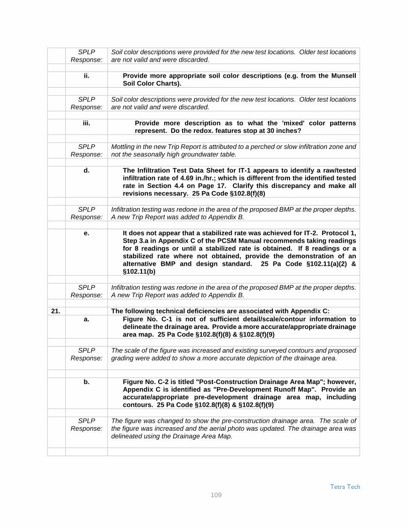
Tetra Tech
109
SPLPResponse:
Soil color descriptions were provided for the new test locations. Older test locationsare not valid and were discarded.
ii. Provide more appropriate soil color descriptions (e.g. from the MunsellSoil Color Charts).
SPLPResponse:
Soil color descriptions were provided for the new test locations. Older test locationsare not valid and were discarded.
iii. Provide more description as to what the 'mixed' color patternsrepresent. Do the redox. features stop at 30 inches?
SPLPResponse:
Mottling in the new Trip Report is attributed to a perched or slow infiltration zone andnot the seasonally high groundwater table.
d. The Infiltration Test Data Sheet for IT-1 appears to identify a raw/testedinfiltration rate of 4.69 in./hr.; which is different from the identified testedrate in Section 4.4 on Page 17. Clarify this discrepancy and make allrevisions necessary. 25 Pa Code §102.8(f)(8)
SPLPResponse:
Infiltration testing was redone in the area of the proposed BMP at the proper depths.A new Trip Report was added to Appendix B.
e. It does not appear that a stabilized rate was achieved for IT-2. Protocol 1,Step 3.a in Appendix C of the PCSM Manual recommends taking readingsfor 8 readings or until a stabilized rate is obtained. If 8 readings or astabilized rate where not obtained, provide the demonstration of analternative BMP and design standard. 25 Pa Code §102.11(a)(2) &§102.11(b)
SPLPResponse:
Infiltration testing was redone in the area of the proposed BMP at the proper depths.A new Trip Report was added to Appendix B.
21. The following technical deficiencies are associated with Appendix C:a. Figure No. C-1 is not of sufficient detail/scale/contour information to
delineate the drainage area. Provide a more accurate/appropriate drainagearea map. 25 Pa Code §102.8(f)(8) & §102.8(f)(9)
SPLPResponse:
The scale of the figure was increased and existing surveyed contours and proposedgrading were added to show a more accurate depiction of the drainage area.
b. Figure No. C-2 is titled "Post-Construction Drainage Area Map"; however,Appendix C is identified as "Pre-Development Runoff Map". Provide anaccurate/appropriate pre-development drainage area map, includingcontours. 25 Pa Code §102.8(f)(8) & §102.8(f)(9)
SPLPResponse:
The figure was changed to show the pre-construction drainage area. The scale ofthe figure was increased and the aerial photo was updated. The drainage area wasdelineated using the Drainage Area Map.

Tetra Tech
110
Page 7422. Figure No. D-1 in Appendix D is not of sufficient detail/scale/contour
information to delineate the drainage area. Provide an accurate/appropriatepost-development drainage area map, including contours, and identify theTime of Concentration Path. 25 Pa Code §102.8(f)(8) & §102.8(f)(9)
SPLPResponse:
The scale of the figure was increased, the aerial photo was updated, and proposedgrading were added to show a more accurate depiction of the drainage area. Thetime of concentration is not shown because it is very short and the minimum Tc wasused.
23. The following technical deficiencies are associated with Appendix E:a. Provide the hydrographs and routings for all regulatory storm events. In the
hydrographs identify the drainage area, Curve Number (CN), Time ofConcentration (Tc), etc. 25 Pa Code §102.8(f)(8)
SPLPResponse:
The hydrographs and routings for all storm events were added to the PondPackreport in Appendix E.
b. Identify the invert elevation for Culvert-1. The calculations identify a slope of2.0% and a length of 50 ft.; however, the PCSM Plan drawings identify a slopeof less than 1% and a length of approx. 104 ft. Clarify these discrepancies. 25Pa Code §102.8(f)(8) & §102.8(f)(9)
SPLPResponse:
The calculation was revised to show a pipe length that matches the drawing.
24. The following technical deficiencies are associated with Appendix F:a. Section 3.9 on Page 13 identifies the receiving surface water to be
impaired; however, PCSM Standard Worksheet #1 does not identify thereceiving surface water as impaired. Clarify this discrepancy. 25 Pa Code§102.8(f)(5) & §102.8(g)(1)
SPLPResponse:
Section 3.9 of the PCSM narrative has been updated to reflect that the receivingwaters are classified as Trout Stock Fisheries (TSF) with a designated use ofattaining.
b. PCSM Standard Worksheet #2 identifies existing natural sensitiveresources, but does not identify their Total Area. If an existing naturalsensitive resource is mapped, then identify its Total Area. 25 Pa Code§102.8(f)(3) & §102.8(g)(1)
SPLPResponse:
The total area was added to Worksheet #2 for the mapped wetland.
c. The following technical deficiencies are associated with PCSM StandardWorksheet #4:
i. The Managed Site Area is identified as 2.83 ac.; however, only 0.632ac. was analyzed. Clarify this discrepancy. 25 Pa Code §102.8(f)(8),§102.8(g)(2) & §102.8(g)(4)

Tetra Tech
111
SPLPResponse:
The LOD was used as the managed site area. The drainage area of 0.63 acres iswhat is controlled by the PCSM BMP. The land cover outside of the 0.63 acres isnot changed between the pre-development and post-development condition;therefore, including it in the analysis would have no effect on the volume increasedcalculation.
ii. Hydrologic Soil Groups (HSG) C & D utilize different CNs for all typesof ground cover, except impervious. Provide discussion as to whyHSGs C & D were combined. 25 Pa Code §102.8(f)(8), §102.8(f)(15),§102.8(g)(2) & §102.8(g)(4)
SPLPResponse:
The soils in the analyzed area include Blairton silt loam. This soil type has a HSGrating of C/D according to the NRCS Web Soil Survey. The CN for C/D soils wascalculated by assuming half C soils and half D soils for each type of land cover.
Page 75iii. Identify how the CNs of 85 & 90 were determined for the gravel areas
for HSGs B & C/D. PCSM Plan drawing C-3 appears to identify, thegravel pad as PennDOT #2A stone; which is a highly compactablestone and will act like an impervious surface. Provide discussion asto why a PennDOT #2A stone was not modeled as an impervioussurface. 25 Pa Code §102.8(0(8), §102.8(f)(15), §102.8(g)(2) &§102.8(g)(4)
SPLPResponse:
All proposed gravel areas were re-assigned a CN of 98 in the calculations.
d. Utilize the latest version of the PCSM Standard Worksheet #5.Identify/provide calculations as to how the volume to be permanentlyreduced was calculated. Provide the Area for the PCSM BMP. 25 Pa Code§102.8(f)(8), §102.8(f)(15), §102.8(g)(2) & §102.8(g)(4)
SPLPResponse:
The latest version of the PCSM standard Worksheet #5 was used as the templatefor the worksheet. The volume reduced is equal to the volume contained below thelowest orifice that allows discharge through the riser (0.142 ac-ft as shown in Table4.3 of the PCSM Report). The area of the PCSM BMP was provided as well.
e. PCSM Standard Worksheet #10 identifies PCSM BMPs to be utilized;however, there is little to no information related to these PCSM BMPsprovided throughout the PCSM Plan. Provide the regulatory requiredinformation for each PCSM BMP utilized in the design (e.g. narrativediscussion, long-term operation and maintenance schedule, plan location,etc.). 25 Pa Code §102.8(f)(6), §102.8(f)(7), §102.8(f)(9) & §102.8(f)(10)
SPLPResponse:
Information was added to Sections 3.1 and 3.8 of the PCSM Report on the BMPsincluded in Worksheet #10.
f. The following technical deficiencies are associated with Stormwater BMPInformation Chart 5.B:
i. It is identified that a Safety Factor of 2 was utilized; however, thecalculations do not appear to have utilized a Safety Factor. Clarify thisdiscrepancy. 25 Pa Code §102.8(f)(8)
SPLPResponse:
A safety factor of 3 was used and added to the calculations in section 4.4 of thePCSM Report.
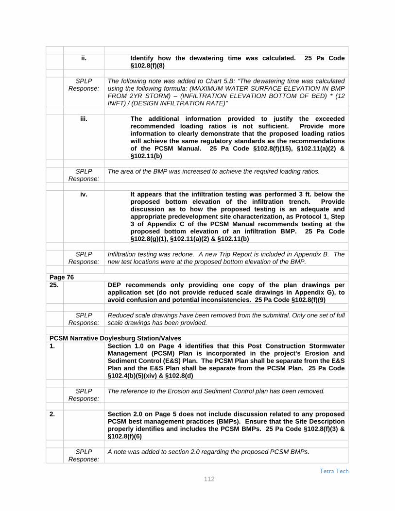
Tetra Tech
112
ii. Identify how the dewatering time was calculated. 25 Pa Code§102.8(f)(8)
SPLPResponse:
The following note was added to Chart 5.B: “The dewatering time was calculatedusing the following formula: (MAXIMUM WATER SURFACE ELEVATION IN BMPFROM 2YR STORM) – (INFILTRATION ELEVATION BOTTOM OF BED) * (12IN/FT) / (DESIGN INFILTRATION RATE)”
iii. The additional information provided to justify the exceededrecommended loading ratios is not sufficient. Provide moreinformation to clearly demonstrate that the proposed loading ratioswill achieve the same regulatory standards as the recommendationsof the PCSM Manual. 25 Pa Code §102.8(f)(15), §102.11(a)(2) &§102.11(b)
SPLPResponse:
The area of the BMP was increased to achieve the required loading ratios.
iv. It appears that the infiltration testing was performed 3 ft. below theproposed bottom elevation of the infiltration trench. Providediscussion as to how the proposed testing is an adequate andappropriate predevelopment site characterization, as Protocol 1, Step3 of Appendix C of the PCSM Manual recommends testing at theproposed bottom elevation of an infiltration BMP. 25 Pa Code§102.8(g)(1), §102.11(a)(2) & §102.11(b)
SPLPResponse:
Infiltration testing was redone. A new Trip Report is included in Appendix B. Thenew test locations were at the proposed bottom elevation of the BMP.
Page 7625. DEP recommends only providing one copy of the plan drawings per
application set (do not provide reduced scale drawings in Appendix G), toavoid confusion and potential inconsistencies. 25 Pa Code §102.8(f)(9)
SPLPResponse:
Reduced scale drawings have been removed from the submittal. Only one set of fullscale drawings has been provided.
PCSM Narrative Doylesburg Station/Valves1. Section 1.0 on Page 4 identifies that this Post Construction Stormwater
Management (PCSM) Plan is incorporated in the project's Erosion andSediment Control (E&S) Plan. The PCSM Plan shall be separate from the E&SPlan and the E&S Plan shall be separate from the PCSM Plan. 25 Pa Code§102.4(b)(5)(xiv) & §102.8(d)
SPLPResponse:
The reference to the Erosion and Sediment Control plan has been removed.
2. Section 2.0 on Page 5 does not include discussion related to any proposedPCSM best management practices (BMPs). Ensure that the Site Descriptionproperly identifies and includes the PCSM BMPs. 25 Pa Code §102.8(f)(3) &§102.8(f)(6)
SPLPResponse:
A note was added to section 2.0 regarding the proposed PCSM BMPs.

Tetra Tech
113
3. Section 2.2 on Pages 5-6 provides for soil resolutions, but does not identifythe site specific soils or their limitations. Provide the site specific soils,limitations and appropriate resolution for this soil limitation for the postconstruction condition and how the project was designed to address thelimitation for the PCSM BMPs. 25 Pa Code §102.8(f)(2), §102.8(f)(12) &§102.8(g)(5)
SPLPResponse:
Section 2.2 of the PCSM narrative has been updated to include site specific soilinformation and limitations.
4. Section 2.3 on Page 6 identifies the waters are designated as attained,supporting recreation, but fails to identify that the water is also attained,supporting aquatic life. Update accordingly. 25 Pa Code §102.8(f)(5)
SPLPResponse:
A note was added to Section 2.3 regarding the identified water supporting aquaticlife.
5. Section 2.3 on Page 6 identifies "This E&SC plan..." This is the narrative forthe PCSM Plan for the Doylesburg Station site. The PCSM Plan shall beseparate from the E&S Plan and the E&S Plan shall be separate from the PCSMPlan. Make all revisions necessary. 25 Pa Code §102.4(b)(5)(xiv) & §102.8(d)
SPLPResponse:
The reference to the Erosion and Sediment Control plan has been removed.
6. The following technical deficiencies are associated with Section 3.1 startingon Page 7: 25 Pa Code §102.8(f)(7)
a. The first sentence references the E&S plan drawings for the PCSM BMPs.This does not meet regulation. The PCSM Plan must be the documentreferenced for the PCSM BMPs. Make all revisions necessary.
SPLPResponse:
The reference to the Erosion and Sediment Control plan has been removed.
b. It is identified that "It is not intended that the drawings and this reportshow detailed information on methods and materials." This statementdoes not meet regulations. The E&S and PCSM Plans shall be final forconstruction, and the information, details and provide the methods andmaterials to properly construct and implement the Plans, including theBMPs, as part of the construction sequences associated with these Plans.25 Pa Code §102.4(b)(5)(xiv) & §102.8(d)
SPLPResponse:
The statement quoted was in reference to "methods and materials" needed for theconstruction of the structural equipment on site and not the PCSM BMPs. Toeliminate confusion, the statement has been removed.
Page 77c. The narrative identifies that the contractor can deviate from the authorized
E&S and PCSM Plans based upon field conditions. A deviation from theauthorized plans may be necessary; however, the appropriate countyconservation district and DEP have to approve any deviation to theauthorized plans. Make all revisions necessary to clearly identify thisrequirement.

Tetra Tech
114
SPLPResponse:
The statement has been adjusted to require approval from PCCD and PADEP priorto plan deviation.
d. Provide a schedule of inspections for critical stages of PCSM BMPinstallation with the construction sequence.
SPLPResponse:
Section 3.1 of the PCSM narrative has been updated to address that licensedprofessional shall oversee all inspection and testing of the proposed BMPs. Forspecific operation and maintenance schedules please reference Section 3.8 of thePCSM narrative.
e. The specific construction sequence for the Level Spreader Installationneed to be specific to the site design and details. The sequence indicatesto protect the lip and for permanent installations the material shall be anon-erodible material, such as pressure-treated timbers or concretecurbing. The Detail on the plan does not reflect this. Clarify if the levelspreader is permanent and ensure the detail on the plan matches theconstruction sequence.
SPLPResponse:
The installation sequence in section 3.1 of the PCSM Plan was revised to be specificand indicate a permanent installation with a concrete curb.
f. Step 2 in construction sequence for the Underground Storage PipeInstallation references reinforced concrete boxes; however, the PCSMPlan does not appear to identify concrete boxes as part of the design.Ensure that the construction sequence is written for the BMP that isdesigned.
SPLPResponse:
Reinforced concrete boxes will not be used at the Doylesburg Station for theUnderground Storage Pipes. Section 3.1 of the PCSM has been updated to reflectthis.
g. More information is required in Step 3 in construction sequence for theUnderground Storage Pipe Installation related to how to properly excavatefor the infiltration trench. Identify how the trench will be constructed (Willthe trench be excavated from the sides? If not, how will the heavyequipment be used so that the underlying soil is not compacted? Etc.).Identify how the contractor will lightly compact the stone withoutcompacting the underlying soil.
SPLPResponse:
The sequence in Section 3.1 for the underground storage pipes was revised toindicate that heavy equipment shall not enter the trench and that stone will be spreadand self-compacted under its own weight instead of compaction with equipment.
7. Section 3.5 on Page 13 is not sufficient as it does not provide for procedureswhich ensure that the proper measures for recycling or disposal of materialsassociated with or from the PCSM BMPs are in accordance with Departmentlaws, regulations and requirements. 25 Pa Code §102.8(f)(11)

Tetra Tech
115
SPLPResponse:
Section 3.5 in the PCSM narrative states that the "operator will remove from the site,recycle, or dispose of all building materials and wastes in accordance with PADEP’ssolid waste management regulations at 25 PA Code 260.1 et seq., 271.1 et seq.,and 287.1 et seq ". The following additional waste management procedures wereadded to the narrative in section 3.5: “The operator will first characterize the wastematerials as municipal, residual or hazardous waste. Before the waste material ishauled away, the material will be stored and labeled in accordance with theapplicable management procedures, if any, under the Solid Waste Management Actregulations. The operator will then hire a licensed and insured waste hauler totransport the waste material to a properly permitted waste disposal facility.”
8. Section 3.6 on Page 14 is not sufficient as there is no clear demonstration thatthe thermal impacts will be mitigated by the minimized clearing duringconstruction and by permanent stabilization as soon as practicable. Thisthermal impact analysis appears to be more for the E&S Plan than for thePCSM Plan. Provide an appropriate thermal impact analysis specific to thePCSM Plan for this location. 25 Pa Code §102.8(f)(13)
SPLPResponse:
Section 3.6 of the PCSM narrative has been updated to address how the proposedpost-construction stormwater BMPs will minimize pollution to receiving waters dueto thermal impact.
Page 789. The following technical deficiencies are associated with Section 3.8 starting
on Page 14: 25 Pa Code §102.8(f)(10)a. It appears that information related to the E&S Plan and activities during
construction are included in this narrative. The PCSM Plan shall beseparate from the E&S Plan and the E&S Plan shall be separate from thePCSM Plan. 25 Pa Code §102.4(b)(5)(xiv) & §102.8(d)
SPLPResponse:
The PCSM narrative has been updated to only address post-constructionstormwater BMPs and their associated installation, operation, and maintenance. Allinformation regarding E&S controls can be found in the E&SC narrative
b. The long-term operation and maintenance schedule indicates theStormwater BMPs can be altered or removed only after approval by themunicipality. Stormwater BMPs can only be altered or removed afterapproval by DEP as well. Update accordingly.
SPLPResponse:
Section 3.8 of the PCSM has been updated to address that BMPs may only bealtered or removed after approval from the municipality and the Department ofEnvironmental Protection.
c. The maintenance schedule for the level spreader indicates to inspect thechannel to the level spreader annually. Provide a demonstration to verifythat only an annual inspection is appropriate to ensure proper functionand operation. Since the conveyance channel is critical to the PCSMdesign, it needs to be included as a PCSM BMP and have proper operationand maintenance. Provide for repair, replacement and other routinemaintenance for the channels.

Tetra Tech
116
SPLPResponse:
Section 3.8 of the PCSM narrative states that the Level Spreader shall be inspectedquarterly for the first two years following installation, and then on a semiannual basisthereafter. The conveyance channel shall be inspected annually and within 48 hoursafter every major storm event (>1 inch rainfall depth).The vegetated channeloperation and maintenance information has been included in Section 3.8 of thePCSM narrative.
d. The maintenance schedule for the level spreader indicates to removesediment and debris removal when build up occurs in the clean out.Clarify if/where are the proposed clean outs associated with the levelspreaders.
SPLPResponse:
The Level Spreader does not have any proposed clean outs. Section 3.8 of the CSMnarrative has been updated to reflect this.
e. Provide a measure to inspect the infiltration facility to ensure properfunction and operation. The PCSM Manual recommends inspecting thestorm sewer system associated with an infiltration trench; provide this aspart of the schedule. There is no inspection identified to ensure that theinfiltration bed (underground storage pipe system) is dewatering properly(in accordance with the designed dewatering time); ensure that this criticalinspection is clearly identified and that proper repair, replacement andother routine maintenance is provided for.
SPLPResponse:
Inspection of cleanouts was added in the inspection schedule for the UndergroundStorage Pipes, including measuring drawdown time, if possible during inspections.For more detail regarding long-term operation and maintenance information, pleasereference Section 3.8 of the PCSM narrative.
f. Ensure that appropriate long-term operation and maintenance schedulesare provided for all PCSM BMPs (including any and all PCSM BMPs utilizedon PCSM Standard Worksheet #10).
SPLPResponse:
Long-term operation and maintenance schedule has been provided in Section 3.8of the PCSM narrative, including Worksheet #10 items.
Page 7910. Section 3.9 on Page 16 identifies that the receiving surface water is impaired
for siltation. Identify how this determination was made, as it appears that thereceiving surface water for the Doylesburg Station is attaining its DesignatedUses (i.e. it is not impaired). 25 Pa Code §102.8(f)(5)
SPLPResponse:
The receiving waters are designated as attained, and Section 3.9 of the PCSMnarrative has been updated to reflect that.

Tetra Tech
117
11. If an antidegradation analysis has to be completed, the information providedin Section 3.9 is not sufficient. The narrative identifies that non-dischargealternatives were evaluated; however, there is no discussion related to showwhat was evaluated. It appears that the discussion is focused on the E&S Planand during the earth disturbance activities; provide an antidegradationanalysis for the PCSM Plan. 25 Pa Code §102.8(d), §102.8(f)(6) & 102.8(h)
SPLPResponse:
Section 3.9 of the PCSM narrative was updated to show how the development willcomply with antidegradation requirements. Also, it is expected that minimaldegradation will occur post-construction and that the main concern for degradationis during earth disturbance activities, thus this is what the section addresses.
12. The regulatory requirement is to manage post construction stormwater forstorm events of a 24-hour duration. Make all revisions to appropriatelyidentify the storm events (e.g. Section 3.10 on Page 17). 25 Pa Code§102.8(g)(2) & §102.8(g)(3)
SPLPResponse:
The storm events were labeled as 24-hour events in section 3.10 and section 4.1.
13. Section 3.10 on Page 14 identifies that a single PCSM BMP will manage therunoff volume and rate for the 2-year storm. Provide discussion related towhat PCSM BMPs will manage the runoff rate for the large storm events.Provide discussion in Section 3.10 related to how the runoff water quality isbeing managed. 25 Pa Code §102.8(f)(6) & §102.8(f)(15)
SPLPResponse:
All discussion of how PCSM BMPs control runoff volume and water quality is foundin Section 4.0 of the PCSM report. Section 3.10 was intended to be a summary ofsection 4.0 and will be deleted entirely since it contains no additional information.
14. Section 3.10 identifies the BMP as an infiltration filter with perforated pipingfor additional storage. However the BMP is referenced differently within thenarrative and on the PCSM plan. In accordance with the PCSM Manual, theBMP appears to be a subsurface infiltration bed. Ensure that the type of PCSMBMP is properly identified and all the necessary information is provided withinthe PCSM plan. 25 Pa Code §102.8(f)(6) & §102.8(f)(10)
SPLPResponse:
All discussion of how PCSM BMPs control runoff volume and water quality is foundin Section 4.0 of the PCSM report. Section 3.10 was intended to be a summary ofsection 4.0 and will be deleted entirely since it contains no additional information

Tetra Tech
118
15. Section 4.1 on Page 18 identifies that the PCSM Plan is designed to complywith the Perry County SWM Plan and the state regulations. Worksheet #1 inAppendix F indicates that there is an approved Act 167 Plan. Attachment V tothe NOI identifies that there is no approved Countywide Act 167 Plan, butidentifies the adopted plan as Terry County Subdivision and LandDevelopment Ordinance w/ Stormwater Requirements' which is indicated tobe approved in 2008. Clarify if there is an adopted Act 167 Plan, as this chartseems to imply that the 'Perry County Subdivision and Land DevelopmentOrdinance w/ Stormwater Requirements' is an adopted Act 167 Plan. The postconstruction stormwater shall be managed as specified in an applicableDepartment approved and current Act 167 stormwater management plan, asidentified in the regulations (25 Pa Code §102.8(g)(2) & §102.8(g)(3)), or to allalternative design standard (per 25 Pa Code §102.8(g)(2)(iv) & §102.8(g)(3)(iii)).Clearly identify the design standards used for this PCSM Plan. If an alternativedesign standard was utilized, ensure that all required information is providedto make the alternative design demonstration. Make all revisions necessarythroughout all of the application documents.
SPLPResponse:
The introduction paragraph of section 4.1 was revised as follows: “This plan hasbeen prepared to comply with the Pennsylvania Stormwater Best ManagementPractices Manual.” The Township/County Act 167 plan is not approved and was notused in the design. Worksheet #1 was revised to indicate that the Act 167 Plan isnot approved.
Page 8016. It is not clear how the rainfall depths were determined, as identified in Section
4.1 on Page 18. Clearly identify how the utilized rainfall depths weredetermined for each location (i.e. regulator station, compressor station,permanent access road, etc.). Chapter 8 (Page 6) of the PCSM Manualrecommends utilizing the rainfall data from the NOAA Atlas 14. If therecommendations of the PCSM Manual are not followed provide ademonstration which identifies how the alternative BMP and design standardwill achieve the same regulatory standards as the recommendations of thePCSM Manual. 25 Pa Code §102.8(f)(8), §102.8(f)(15), §102.8(g)(2), §102.8(g)(3),§102.8(g)(4), §102.11(a)(2) & §102.11(b)
SPLPResponse:
The NOAA Atlas 14 rainfall data was added to Appendix E. Section 4.1 of the PCSMnarrative was edited to clarify this as the source of the rainfall data.
17. Provide additional information/calculations to clarify how the volumes werecalculated in Table 2 starting on Page 19. 25 Pa Code §102.8(f)(8) &§102.8(f)(15)
SPLPResponse:
Footnotes were added to Table 2 to clarify how the storage volumes were calculatedfor pipe storage. The table rows were also inverted to correspond to the input forthe pond elevation/volume table for PondPack in Appendix E.
18. Section 4.3, Table 3 is labeled as `BMP-4 Routing Summary POI-2 Basin'. Thereport indicates there is only 1 POI and there is no 'basin' proposed. Clarifythe discrepancy. 25 Pa Code §102.8(f)(8) & §102.8(f)(15)
SPLPResponse:
The title of the table was revised to indicate only one BMP that is not a basin.

Tetra Tech
119
19. Identify if a Safety Factor was utilized in the infiltrate rate for design purposes(in Section 4.4 on Starting on Page 20). If a Safety Factor was utilized, identifythe Safety Factor and identify how it was determined. If a Safety Factor wasnot utilized, provide discussion as to why a Safety Factor was not utilized (asrecommended on Page 19 of Appendix C of the PCSM Manual). Make allrevisions necessary. 25 Pa Code §102.8(f)(8), §102.8(g)(2), §102.8(g)(3),§102.8(g)(4), §102.11(a)(2) & §102.11(b)
SPLPResponse:
The infiltration rate was determined to be zero so no safety factor was required.
20. Section 4.4, based on the results of the infiltration testing, no infiltration wasachieved at on test point and an extremely low infiltration rate was achievedat the other test point. Provide a demonstration or additional data to supportthat infiltration is appropriate at the proposed location and depth of theinfiltration BMP. 25 Pa Code §102.8(g)(1)
SPLPResponse:
Infiltration testing was redone in approximately the same location as previousinfiltration testing. The results again indicated that there was little to no infiltration inthe underlying soils. Because of the low infiltration rates in the underlying soil, SPLPredesigned the infiltration BMP to provide for the installation of a slow releaseunderdrain to ensure that the 2-year control volume is released over a 24 to 72 hourperiod.
21. Section 4.5 on Page 21 identifies that E&S details are included in the landdevelopment plans; however, this is not in accordance with the regulations.For the ESCGP-2 Permit, provide the regulatory required information in theE&S Plan. Make all revisions necessary. 25 Pa Code §102.4(b)(5),§102.4(b)(5)(xiv) & §102.8(d)
SPLPResponse:
Section 4.5 in the PCSM narrative has been updated to only provide informationpertinent to the PCSM Plan. All regulatory required information for the ESCGP-2permit can be found in the E&S narrative and plan drawings.
22. Section 5.0 on Page 23 references the Pennsylvania Storrs water BestManagement Practices Manual Draft, Pennsylvania Department ofEnvironmental Protection, Bureau of Watershed Management, October, 2009.This referenced manual is not the current PCSM Manual. The current PCSMManual is dated December 30, 2006 with DEP Document No. 363-0300-002.Identify the DEP Document Number for the referenced manual. If the PCSMPlan and BMPs were not designed to the current version of the PCSM Manual,then all designs will be considered an alternative 13MP and design standard.Provide all required information and make all revisions necessary. 25 Pa Code§102.11(a)(2) & §102.11(b)
SPLPResponse:
The publication date was incorrect and revised to be December 2006. Thedocument number was also added. The December 2006 document was used for alldesigns.
Page 8123. Since the channels are critical to the PCSM design, they are considered PCSM
BMPs.a. Provide associated operation and maintenance schedule and calculations.
25 Pa Code §102.8(f)(8) & §102.8(f)(10)

Tetra Tech
120
SPLPResponse:
An operation and maintenance schedule has been provided in Section 3.8 of thePCSM narrative.
b. Demonstrate that the proposed bypass channels can safely bypass theflow from a 100 year storm event to allow the other BMPs to function asdesigned. 25 Pa Code §102.8(f)(8)
SPLPResponse:
Worksheet #11 has been filled out for the proposed channels and included in theE&S Report. Channel A and Channel B proposed for E&S control will becomepermanent after construction.
c. Provide calculations for the existing channel and ensure that theadditional flow will be stable and the channel will function as designed. 25Pa Code §102.8(f)(8)
SPLPResponse:
The calculation for the existing channel was included on Worksheet #11 in the E&SReport.
24. The following technical deficiencies are associated with the Trip Report inAppendix B:
a. Figure 1 is not a sufficient location map for the testing. Provide andidentify the test locations on the PCSM Plan drawings, so that DEP canevaluate their location versus the location of the PCSM BMPs. 25 Pa Code§102.8(f)(9) & §102.8(g)(1)
SPLPResponse:
Figure 1 was revised for the new test locations. Older test locations are not validand were discarded.
b. Provide more appropriate soil color descriptions (e.g. from the MunsellSoil Color Charts) in the Soil Log. 25 Pa Code §102.8(g)(1)
SPLPResponse:
Soil color descriptions were provided for the new test locations. Older test locationsare not valid and were discarded.
c. The trip report indicates that the infiltration test depths were at 18 inchesfrom surface for TP-1 and 12 inches from the surface for TP-2). It alsoindicates that test pits were completed to two feet below the targetinfiltration test depths. The soil logs appear to only go to 28" below thesurface. Clarify the discrepancy and provide documentation to ensurethat is 2 feet separation from the proposed bottom of the infiltrationfacility. 25 Pa Code §102.8(g)(1) & §102.11(a)(2)
SPLPResponse:
Infiltration testing was redone in the area of the proposed BMP at the proper depths.A new Trip Report was added to the Appendix B.
25. Figure No. C-1 in Appendix C, is not of sufficient detail/scale/contourinformation to delineate the drainage area. Provide a moreaccurate/appropriate drainage area map. 25 Pa Code §102.8(f)(8) & §102.8(f)(9)

Tetra Tech
121
SPLPResponse:
The figure was revised to include more detailed topography and grading to bettershow the drainage area delineation.
26. Figure No. D-1 in Appendix D is not of sufficient detail/scale/contourinformation to delineate the drainage area. Provide an accurate/appropriatepost-development drainage area map, including contours and identify theTime of Concentration Path. 25 Pa Code §102.8(f)(8) & §102.8(f)(9)
SPLPResponse:
The figure was revised to include more detailed topography and grading to bettershow the drainage area delineation.
Page 8227. The following technical deficiencies are associated with Appendix E:
a. Provide the hydrographs and routings for all regulatory storm events.Provide the drainage area, Curve Number (CN), Time of Concentration (Tc),etc. with the hydrographs. 25 Pa Code §102.8(f)(8)
SPLPResponse:
The hydrographs and routings for all storm events were added to the PondPackreport in Appendix E.
b. The pond elevation and pond volume table on page 5 of 10, does notcorrelate to the Cumulative storage volume table on pages 19-20 of thePCSM narrative. Clarify the discrepancy.
SPLPResponse:
The table in the PCSM narrative was revised and notes were added that clarify howthe elevations match what was used in the PondPack calculations.
c. The outlet pipe data indicates that the outlet input data indicates that theculvert 1 is 20 feet, but the plan shows the outlet pipe at approximately 75linear feet. Clarify the discrepancy. 25 Pa Code §102.8(f)(8)
SPLPResponse:
The calculation was revised to show a pipe length that matches the drawing.
d. Clarify the existing type of gravel on the site if 20% of the existingimpervious area to be disturbed has been considered meadow in goodcondition. 25 Pa Code §102.8(g)(2)(i)
SPLPResponse:
20% of the existing impervious area was changed to meadow in good condition inthe PondPack model.
28 The following technical deficiencies are associated with Appendix F:a. The following technical deficiencies are associated with PCSM Standard
Worksheet #4:i. The Managed Site Area is identified as 1.68 ac.; however, 8.17 acres
were analyzed. Clarify this discrepancy. 25 Pa Code §102.8(f)(8),§102.8(g)(2) & §102.8(g)(4)
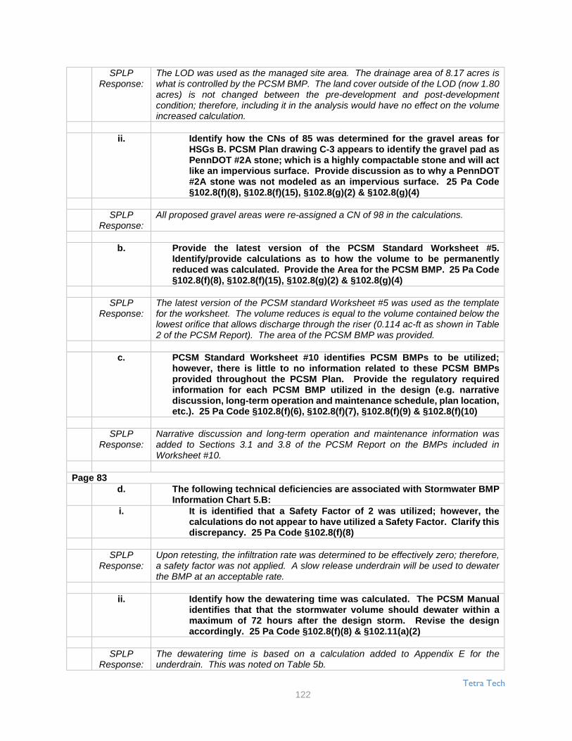
Tetra Tech
122
SPLPResponse:
The LOD was used as the managed site area. The drainage area of 8.17 acres iswhat is controlled by the PCSM BMP. The land cover outside of the LOD (now 1.80acres) is not changed between the pre-development and post-developmentcondition; therefore, including it in the analysis would have no effect on the volumeincreased calculation.
ii. Identify how the CNs of 85 was determined for the gravel areas forHSGs B. PCSM Plan drawing C-3 appears to identify the gravel pad asPennDOT #2A stone; which is a highly compactable stone and will actlike an impervious surface. Provide discussion as to why a PennDOT#2A stone was not modeled as an impervious surface. 25 Pa Code§102.8(f)(8), §102.8(f)(15), §102.8(g)(2) & §102.8(g)(4)
SPLPResponse:
All proposed gravel areas were re-assigned a CN of 98 in the calculations.
b. Provide the latest version of the PCSM Standard Worksheet #5.Identify/provide calculations as to how the volume to be permanentlyreduced was calculated. Provide the Area for the PCSM BMP. 25 Pa Code§102.8(f)(8), §102.8(f)(15), §102.8(g)(2) & §102.8(g)(4)
SPLPResponse:
The latest version of the PCSM standard Worksheet #5 was used as the templatefor the worksheet. The volume reduces is equal to the volume contained below thelowest orifice that allows discharge through the riser (0.114 ac-ft as shown in Table2 of the PCSM Report). The area of the PCSM BMP was provided.
c. PCSM Standard Worksheet #10 identifies PCSM BMPs to be utilized;however, there is little to no information related to these PCSM BMPsprovided throughout the PCSM Plan. Provide the regulatory requiredinformation for each PCSM BMP utilized in the design (e.g. narrativediscussion, long-term operation and maintenance schedule, plan location,etc.). 25 Pa Code §102.8(f)(6), §102.8(f)(7), §102.8(f)(9) & §102.8(f)(10)
SPLPResponse:
Narrative discussion and long-term operation and maintenance information wasadded to Sections 3.1 and 3.8 of the PCSM Report on the BMPs included inWorksheet #10.
Page 83d. The following technical deficiencies are associated with Stormwater BMP
Information Chart 5.B:i. It is identified that a Safety Factor of 2 was utilized; however, the
calculations do not appear to have utilized a Safety Factor. Clarify thisdiscrepancy. 25 Pa Code §102.8(f)(8)
SPLPResponse:
Upon retesting, the infiltration rate was determined to be effectively zero; therefore,a safety factor was not applied. A slow release underdrain will be used to dewaterthe BMP at an acceptable rate.
ii. Identify how the dewatering time was calculated. The PCSM Manualidentifies that that the stormwater volume should dewater within amaximum of 72 hours after the design storm. Revise the designaccordingly. 25 Pa Code §102.8(f)(8) & §102.11(a)(2)
SPLPResponse:
The dewatering time is based on a calculation added to Appendix E for theunderdrain. This was noted on Table 5b.

Tetra Tech
123
iii. The additional information provided to justify the exceededrecommended loading ratios is not sufficient. Provide moreinformation to clearly demonstrate that the proposed loading ratioswill achieve the same regulatory standards as the recommendationsof the PCSM Manual. 25 Pa Code §102.8(f)(15), §102.11(a)(2) &§102.11(b)
SPLPResponse:
The area of the BMP was increased to achieve the required loading ratios.
iv. It appears that the infiltration testing was performed 3 ft. above theproposed bottom elevation of the infiltration facility. Providediscussion as to how the proposed testing is an adequate andappropriate predevelopment site characterization, as Protocol 1, Step3 of Appendix C of the PCSM Manual recommends testing at theproposed bottom elevation of an infiltration BMP (ensure that the soilprofiles have been investigated at least 2 feet below the bottom of theinfiltration BMP). 25 Pa Code §102.8(g)(1), §102.11(a)(2) & §102.11(b)
SPLPResponse:
Infiltration testing was redone. A new Trip Report is included in Appendix B. Thenew test locations were at the proposed bottom elevation of the BMP.
29. DEP recommends only providing one copy of the plan drawings perapplication set (do not provide reduced scale drawings in Appendix G), toavoid confusion and potential inconsistencies. 25 Pa Code §102.8(f)(9)
SPLPResponse:
Reduced scale drawings have been removed from the submittal. Only one set of fullscale drawings has been provided.
PCSM Narrative Middletown Pump Station1. Identify to what standards the PCSM Plan was designed and planned (i.e. Act
167 Plan, 25 Pa Code §102.8(g)(2) & §102.8(g)(3), or an alternative designstandard per 25 Pa Code §102.8(g)(2)(iv) & §102.8(g)(3)(iii)).
SPLPResponse:
The PCSM plan was designed to meet the Londonderry Township SALDO and thePA Stormwater BMP Manual. See Section 2.0 of the PCSM Report
Page 842. Section 2.0 indicates that the Worksheets # 4 & 5 are included in Appendix D,
but the Worksheets are located in Appendix E. Clarify the discrepancy. 25 PaCode §102.8(f)(3) & §102.8(f)(6)
SPLPResponse:
The worksheets have been moved to Appendix D.
3. It is not clear how the rainfall depths were determined, as identified in Section2.0. Clearly identify how the utilized rainfall depths were determined. Chapter8 (Page 6) of the PCSM Manual recommends utilizing the rainfall data from theNOAA Atlas 14. If the recommendations of the PCSM Manual are not followedprovide a demonstration which identifies how the alternative BMP and designstandard will achieve the same regulatory standards as the recommendationsof the PCSM Manual. 25 Pa Code §102.8(f)(8), §102.8(f)(15), 102.8(g)(2),102.8(g)(3), §102.8(g)(4), §102.11(a)(2) & §102.11(b)

Tetra Tech
124
SPLPResponse:
SPLP revised the PCSM calculations to utilize the rainfall data from the NOAA Atlas14.
4. Section 3.0 indicates that the pre-development has a single point of discharge.However, based on the existing contours, surface waters and assumedproperty lines shown on the plan, there needs to be at least 3 points ofdischarge: (1) Draining to the North to an UNT to Swatara Creek, (2) drainingto a wetland from a central portion of the access drive, and (3) draining to thesouth to an UNT to Swatara Creek. Reevaluate the points of the discharge andupdate the application accordingly. 25 Pa Code §102.8(f)(4)
SPLPResponse:
The plans and reports have been revised to include three, pre-developed points ofinterest, as recommended. For that reason, several additional BMPs have beenadded to the PCSM design.
5. Clearly identify the drainage areas and delineate the boundaries on the pre-development and post-development drainage area maps. While the maps areprovided, the drainage areas are not clear. 25 Pa Code §102.8(f)(4) &§102.8(f)(9)
SPLPResponse:
Drainage area lines have been updated to clearly delineate the boundaries.
6. Provide documentation to support the CN utilized in the analysis, includingidentifying the specific soils Hydraulic Soil Group (HSG) and the input dataand calculations used to achieve the weighted CN values. 25 Pa Code§102.8(f)(8)
SPLPResponse:
The majority of the soils on site and within the disturbed area are consideredLewisberry gravelly sandy loam, which are classified as HSG “B” type soils.Additional data and calculations to determine the weighted CN values are includedwithin the PondPack report, Appendix C and D.
7. Provide documentation to support the Time of Concentration utilized in theanalysis. 25 Pa Code §102.8(f)(8)
SPLPResponse:
Assumed pre-developed Tc flow paths have been added to the drainage area maps,for time periods over 5 minutes. Tc calculations are also shown in the PondPackreport. For all post developed drainage areas, a Tc of 5 minutes was assumed forthe calculations, therefore a Tc flow path was not shown on the plan.
8. The pre-development and post-development runoff calculations, utilized at 96-hour storm duration for each of the storm events. The regulations requiredutilizing a 24-hour duration for each storm event. Update the calculationsaccordingly. 25 Pa Code §102.8(g)(3)
SPLPResponse:
The PondPack model was revised to utilize a 24 hour time duration. The 96 hourtime period shown in the previous report is the time span used to achieve full volumefor the hydrograph, not the storm duration. Each peak flow is calculated based onthe 24 hour storm rainfall depth. Changing the time span to 24 hours does not affectthe peak flow.

Tetra Tech
125
9. The post-developed drainage areas (area and CN values) explained in Section3.0, do not correlate directly with the Post-Development Hydrologycalculations in Appendix D. Clarify the discrepancy and clearly explain thedrainage areas and analysis. 25 Pa Code §102.8(f)(8)
SPLPResponse:
The PCSM report was modified to correct any discrepancies between the narrativein Section 3.0 and Appendix D.
Page 8510. Sections 3.0 & 4.0 reference post-development calculations are located in
Appendix C, but Appendix C only contains the pre-development calculations.Clarify the discrepancy. 25 Pa Code §102.8(f)
SPLPResponse:
The PCSM narrative was revised to include the language “Appendix C and D”. Pre-Developed information is shown in Appendix C, post-developed information isshown in Appendix D.
11. The invert elevation (for the 2-inch orifice and overflow for infiltration bed #1do not correlate to the plans. Clarify the discrepancy and ensure thecalculations are consistent. 25 Pa Code §102.8(f)(6), §102.8(f)(8) & §102.8(f)(9)
SPLPResponse:
The 2” orifice was associated with Basin #1, not Infiltration Bed #1.
12. The spillway elevation (354) for Infiltration Bern #2 does not correlate to thedetail on the plan (355). Clarify the discrepancy and ensure the calculationsare consistent. 25 Pa Code §102.8(f)(6), §102.8(f)(8) & §102.8(f)(9)
SPLPResponse:
Infiltration Berm #2 was revised to a SRC basin. The details for SRC Basin #2 areshown on Sheet 9.
13. Section 5.0 identifies that E&S details are included in the land developmentplans; however, this is not in accordance with the regulations. For theESCGP-2 Permit, provide the regulatory required information in the E&S Plan.Make all revisions necessary. 25 Pa Code §102.4(b)(5), §102.4(b)(5)(xiv) &§102.8(d)
SPLPResponse:
The PCSM report was revised to remove the language “included in the LandDevelopment Plans”. The E & S details are included within the E & S Plans.
14. Section 5.0 fails to identify all of the PCSM BMPs, including Detention Basin1. Make all revisions necessary. 25 Pa Code §102.8(f)(6)
SPLPResponse:
Section 5.0 was revised to include SRC Detention Basin #1 and #2, SRC Berm #1,and Detention/Infiltration Beds #1 and #2.
15. In Section 5.0, the infiltration rates identified do not correlate with theinfiltration testing provided in Appendix F. Clarify the discrepancy. 25 PaCode §102.8(f)(6) & §102.8(g)(1)

Tetra Tech
126
SPLPResponse:
The infiltration rates in Section 5.0 were corrected. Please note that the infiltrationtest data sheets shows the volume of water added between each cycle, which is notthe actual infiltration rate (in/hr).
16. In Section 5.0, the volume reduction identified does not correlate toWorksheet #5 or the NOI. Clarify the discrepancy. 25 Pa Code §102.8(f)(6) &§102.8(f)(8)
SPLPResponse:
The volume reduction shown in Section 5.0 was corrected to match the new designfor the infiltration beds and the two SRC Basins.
17. Section 7.0, Provide specific long-term operation and maintenance schedulesfor all PCSM BMPs. The schedule which needs to provide for inspection,needs to include, repair, replacement and other routine maintenance of thePCSM BMPs to ensure proper function and operation. The program mustprovide for completion of a written report documenting each inspection andall BMP repair and maintenance activities and how access to the PCSM BMPswill be provided. Refer the PCSM Manual for reference for the operation andmaintenance for each type of PCSM BMP. 25 Pa Code §102.8(f)(10)
SPLPResponse:
Section 7.0 was revised to include additional long term O & M schedules for allBMPs. Additional information was also added to address repair and replacement ofBMPs and the proper DEP Form to complete for all site inspections.
18. In Section 8.0 and on the PCSM Plans, clarify when the basin is to beconstructed within the Construction Sequence. Ensure to include theinstallation of the outlet structure, specifically, the anti-seep collar as a criticalstages of PCSM BMP installation. 25 Pa Code §102.8(f)(7)
SPLPResponse:
The construction sequence was revised to include the basin construction. Section8.0 was revised to include additional critical stages for Professional oversight. Thesequence was expanded to include the construction of SRC Basins, Beds and SRCBerms.
19. Delineate the site location on the location map in Appendix A. 25 Pa Code§102.8(f)(1)
SPLPResponse:
The site boundary has been added to the location map in Appendix A.
Page 8620. In Appendix D, provide a schematic to explain the runoff analysis, including
the nodes, links and outlet structures. 25 Pa Code §102.8(f)(8) & §102.8(g)(3)
SPLPResponse:
Appendix C and D were revised to include a PondPack node schematic.
21. In Appendix D, clarify that the weir lengths are accurate for both OutletStructure 3 &4, which appears to be associated with infiltration Bemis 1 & 2.It indicates the weir length is 10 feet, but that does not appear to correlate withthe yard drain size shown on the plans. 25 Pa Code §102.8(f)(6) & §102.8(f)(8)

Tetra Tech
127
SPLPResponse:
The weir length of 10’ is accurate for SRC Berm #1. Note that the 2’ x 2’ yard draintop of grate elevation is at 355.0, which is 12” above the spillway crest of 354.0.There will be no flow through the top of the 2’ x 2’ drain. All outflow of this berm isassumed to travel through either the spillway or slowly released through the 4” ballvalve and outlet pipe. See Appendix D.
22. The following comments relate to the Trip Report in Appendix F:a. Section 1.0 indicates single and double ring tests were conducted.
Section 2.0 indicates that only double ring testing was performed. Clarifythe discrepancy. 25 Pa Code §102.8(g)(1)
SPLPResponse:
The tests completed in October, 2015 (TP-1 through TP-5) utilized the double ringmethod. Section 1.0 of the Trip Report was modified to remove the term “Singlering”. The previous report for ME1 completed in March, 2015 utilized the single ringmethod. The ME1 Geotechnical Report is also included within the PCSM narrative,Appendix F.
b. Figure 1 is not a sufficient location map for the testing. Provide andidentify the test locations on the PCSM Plan drawings, so that DEP canevaluate their location versus the location of the PCSM BMPs. 25 Pa Code§102.8(f)(9) & §102.8(g)(1)
SPLPResponse:
All of the infiltration tests completed for this site are shown on Sheet 2 of the PCSMPlans.
c. Provide a table to demonstrate the infiltration test elevation, the proposedelevation at the bottom of the infiltration facility and the depth of the soillog to in order to correlate the testing with the proposed design. 25 PaCode §102.8(g)(1)
SPLPResponse:
A soil testing summary table depicting infiltration rate, surface elevation, test depthand elevation and the corresponding infiltration facility elevation is included withinAppendix F.
d. The infiltration testing results do not appear to be related with theproposed PCSM BMP design calculations. For instance the InfiltrationTest Data Sheet for IT-5 appears to correlate to the location of theinfiltration bed #1 Infiltration Test Data Sheet for IT-5 identifies a raw/testedinfiltration rate of 0.3 in./hr.; however an infiltration rate of 1.15 in/hr wasused in the infiltration facilities design on Worksheet #4. Clarify thediscrepancies and ensure the PCSM BMP design calculations reflect theinfiltration testing. 25 Pa Code §102.8(f)(8), §102.8(g)(1) & §102.8(g)(2)
SPLPResponse:
The infiltration test data sheets show the volume of water added between eachcycle, which is not the actual infiltration rate. The actual infiltration rate used iscorrect for each area and a safety factor of “2” was also utilized.
e. Clarify if infiltration is appropriate at Infiltration Berm #1. It appears thetesting in that vicinity resulted in no infiltration. 25 Pa Code §102.8(f)(8),§102.8(g)(1) & §102.8(g)(2)

Tetra Tech
128
SPLPResponse:
SRC Berm #1 has been modified to include a 4” valve in the outlet structure, so thatthe Berm can be slowly dewatered if necessary.
23. The following technical deficiencies are associated with Appendix E:a. Provide the latest version of the PCSM Standard Worksheet #5.
Identify/provide calculations as to how the volume to be permanentlyreduced was calculated. Provide the Area for the PCSM BMP. 25 Pa Code§102.8(f)(8), §102.8(f)(15), §102.8(g)(2) & §102.8(g)(4)
SPLPResponse:
The latest version of Worksheet #5 (8/2016) has been utilized. Additionalcalculations have been provided for the volume removed.
b. The Volumes of Stormwater treated from each BMP on Worksheet #5 doesnot correlate with the Volume of Stormwater treated in Section D.4 of theNotice of Intent. Clarify the discrepancies. 25 Pa Code §102.8(f)(8) &§102.6(a)(1)
SPLPResponse:
The NOI has been modified to match the revised design for this site.
Page 8724. DEP recommends only providing one copy of the plan drawings per
application set (do not provide reduced scale drawings after Appendix F in thenarrative), to avoid confusion and potential inconsistencies. 25 Pa Code§102.4(b)(5)(ix)
SPLPResponse:
All reduced size plans were removed from Appendix F. All soil test locations areshown on the PCSM Plans, Sheet 2.
25. Clarify if the infiltration calculations for the PCSM BMPs account the time ofconcentration or 2 hours as the infiltration Period. If the infiltration periodexceeds the time of concentration or 2 hours as recommended in the PCSMManual, provide a discussion of how the proposed infiltration period willachieve the same regulatory standards as the recommendations of the PCSMManual 25 Pa Code §102.8(f)(8), §102.8(g)(2) & §102.11(a)(2)
SPLPResponse:
A 12 hour infiltration period was utilized for Infiltration Beds #1 and #2, since theorifice is raised above the bottom of the bed and there is no outflow through theorifice for at least 12 hours. The SRC Basins and the SRC Berm did not utilize aninfiltration period.
26. Clarify how the conveyance facilities (i.e. pipes and swales) are designed. Willthey convey the 100 year storm event or was the overflow/bypass accountedfor in the design. Provide conveyance calculations for any stormwaterconveyance features which are critical to the PCSM BMP design. For instanceif the stormwater up to the 100 year storm event is to be managed by a PCSMBMP and the stormwater only reaches the PCSM BMP by being conveyed tothe PCSM BMP through a conveyance feature, calculations demonstrating theconveyance facility can convey the 100-year storm to the PCSM BMP arerequired. The conveyance feature needs to be identified as a PCSM BMP andhave associated Operation and Maintenance. 25 Pa Code §102.8(f)(8) &§102.8(f)(15)

Tetra Tech
129
SPLPResponse:
All pipes and swales were re-designed to convey the 100 year storm. There is nobypass for any of the diversion or collector channels. All proposed storm pipes havesufficient capacity to convey the 100 year storm.
27. Provide procedures which ensure the proper measures for recycling ordisposal of materials associated with or from the PCSM BMPs in accordancewith Department laws, regulations and requirements. 25 Pa Code §102.8(f)(11)
SPLPResponse:
Recycling measures are included within the Construction Sequence, Inspection andMaintenance of Control Facilities, Section 8.0 of the PCSM Report.
28. Provide the proposed loading ratios (total and impervious) and associatedcalculations for each infiltration PCSM BMP. If the loading ratios exceed therecommendations in the PCSM Manual, provide a discussion of how theproposed loading ratios will achieve the same regulatory standards as therecommendations of the PCSM Manual. 25 Pa Code §102.8(f)(15),§102.11(a)(2) & §102.11(b)
SPLPResponse:
Table 5B is included in Appendix E. Loading ratios are met for all BMPs exceptInfiltration Bed #2, which is discharging into another infiltration bed under an existingpaved area.
29. Provide a thermal impact analysis for the project. 25 Pa Code §102.8(f)(13)
SPLPResponse:
A Thermal Impact Analysis is included within the PCSM report, Section 5.0.
30. Provide Worksheets #1-3 for the project. 25 Pa Code §102.6(a)(1), §102.8(g)(1)& §102.8(g)(2)
SPLPResponse:
Worksheets #1 -3 are included in the PCSM report, see Appendix E.
31. Provide an analysis to demonstrate the PCSM BMPs will meet the water qualityrequirements (i.e. Worksheet #10 and/or Worksheets #11-13). Refer to theWater Quality Process Flow chart on page 40 in Chapter 8 of the PCSM Manualfor additional information. 25 Pa Code §102.8(g)(2) & §102.11(a)(2)
SPLPResponse:
Worksheet #10 has been added to the report. If needed, worksheets #11 -#13 havealso be completed.
Page 8832. Clarify if an antidegradation analysis has to be completed. If so, provide an
antidegradation analysis for the PCSM Plan. 25 Pa Code §102.8(d), §102.8(f)(6)& §102.8(h)
SPLPResponse:
An anti-degradation analysis is not required due the project not being within a highquality or exceptional value watershed.

Tetra Tech
130
33. Provide additional information/calculations to clarify how the volumes werecalculated for the infiltration basin and berm(s) in Worksheet #5. 25 Pa Code§102.8(f)(8) & §102.8(f)(15)
SPLPResponse:
The additional information describing how the volume reduction was achieved isshown on Worksheet #4 for the three BMP areas. See Appendix E.
34. Identify if a Safety Factor was utilized in the infiltrate rate for design purposes.If a Safety Factor was utilized, identify the Safety Factor and identify how itwas determined. If a Safety Factor was not utilized, provide discussion as towhy a Safety Factor was not utilized (as recommended on Page 19 of AppendixC of the PCSM Manual). Make all revisions necessary. 25 Pa Code §102.8(f)(8),§102.8(g)(2), §102.8(g)(3), §102.8(g)(4), §102.11(a)(2) & §102.11(b)
SPLPResponse:
A safety factor of 2 was utilized for the infiltration rate, based on the recommendedminimum value allowed in the PA Stormwater BMP Manual.
35. Provide dewatering time calculations of the proposed PCSM BMPs.§102.8(f)(8) & §102.11(a)(2)
SPLPResponse:
Dewatering time calculations are shown in Chart 5B, located in Appendix E.
36. Clarify if the Diversion Channels 1 & 2 will bypass the upstream drainage areafrom the project site. If so, provide calculations supporting that the channelswill be able to convey the 100-year storm event and bypass the project site.25 Pa Code §102.8(f)(4) & §102.8(f)(8)
SPLPResponse:
Diversion Channel #1 bypasses upstream flows away from the access roadway anddischarges into Level Lip Spreader #1. Diversion Channel #2 bypasses upstreamflows away from the access roadway and the SRC Basin #2 area. All channels andpipes were sized for the 100 year storm event.
37. Provide calculations for the design of the level spreader. Ensure the designis in accordance with the PCSM Manual or provide the required informationrelated to the alterative BMP and design standard. 25 Pa Code §102.8(f)(8),§102.11(a)(2) & §102.11(b)
SPLPResponse:
The level spreaders were designed in accordance with the 2012 Erosion andSediment Pollution Control Program Manual, Chapter 9. The Manualrecommendations a design guideline of providing 5 l.f./acre of drainage area, or 1foot of length for every 1 cfs of discharge. Both proposed level spreaders are 20’ inlength for a drainage area of approximately 1.0 acre in size each. The levelspreaders are oversized for the expected flow. Channel #1 was designed for a 100year flow of 2.77 cfs and Channel #4 was sized for a 100 year flow of 2.49 cfs. Bothlevel spreaders are approximately 15’ longer than the design guidelines require, toinsure the diverted runoff is returned to a sheet flow condition.

Tetra Tech
131
PCSM Narrative Beckersville Pump Station1. Section 1.0 indicates that the project area drains via an unnamed tributary
(UNT) to Muddy Creek, however the location map indicates the project sitedrains to an UNT to Rock Run and/or an UNT Alleghany Creek. Clarify thediscrepancy. 25 Pa Code §102.8(f)(5)
SPLPResponse:
The correct tributary is Muddy Creek. The location map was corrected within thereport.
2. Identify to what standards the PCSM Plan was designed and planned (i.e. Act167 Plan, 25 Pa Code §102.8(g)(2) & §102.8(g)(3), or an alternative designstandard per 25 Pa Code §102.8(g)(2)(iv) & §102.8(g)(3)(iii)). Section 2.0identifies that the PCSM Plan is designed to comply with the BrecknockTownship's Subdivision and Land Development Ordinance. Please note thatthe Conestoga River Watershed Act 167 plan is not current. Clearly identifythe design standards used for this PCSM Plan. If an alternative designstandard was utilized, ensure that all required information is provided to makethe alternative design demonstration. Make all revisions necessarythroughout all of the application documents.
SPLPResponse:
The PCSM plan was designed to meet the Township SALDO and the PA StormwaterBMP Manual. This has been added to page 1 of the PCSM report.
Page 893. It is not clear how the rainfall depths were determined, as identified in Section
2.0. Clearly identify how the utilized rainfall depths were determined. Chapter8 (Page 6) of the PCSM Manual recommends utilizing the rainfall data from theNOAA Atlas 14. If the recommendations of the PCSM Manual are not followed,then provide a demonstration which identifies how the alternative BMP anddesign standard will achieve the same regulatory standards as therecommendations of the PCSM Manual. 25 Pa Code §102.8(f)(8), §102.8(f)(15),§102.8(g)(2), §102.8(g)(3), §102.8(g)(4), §102.11(a)(2) & §102.11(b)
SPLPResponse:
SPLP revised the PCSM calculations to utilize the rainfall data from the NOAA Atlas14.
4. In Section 3.0, the narrative indicates that drainage area 1 is routed to a basinand drainage area 2 is undetained. This description of the post developed siteconditions is not consistent with what is shown on the PCSM plans. Clarifythe discrepancy. 25 Pa Code §102.8(f)(6) & §102.8(f)(8)
SPLPResponse:
The labeling for the pre and post developed drainage areas has been corrected onthe PCSM plans and report.
5. Section 3.0 indicates that the pre-development has a single point of interest.However, based on the existing contours and assumed property lines shownon the plan, there needs to be at least 2 points of discharge in order tocompare the post development condition. Reevaluate the points of thedischarge and update the application accordingly. 25 Pa Code §102.8(f)(4) &§102.8(f)(9)

Tetra Tech
132
SPLPResponse:
Since the new basin has been moved south, there is one pre-developed point ofinterest.
6. The peak flowrates in the report do not correlate to the flowrates in the Noticeof Intent (NOI). Clarify the discrepancy. 25 Pa Code §102.6(a)(1) & §102.8(g)(3)
SPLPResponse:
The peak flow rates in the NOI have been revised to match the peak flow rates inthe PCSM narrative.
7. Provide documentation to support the CN utilized in the analysis, includingidentifying the specific soils Hydraulic Soil Group (HSG) and the input dataand calculations used to achieve the weighted CN values. 25 Pa Code§102.8(f)(8)
SPLPResponse:
The majority of the soils on site and within the disturbed area are considered Joannaloam, which are classified as HSG “B” type soils. Additional data and calculations todetermine the weighted CN values are included within the PondPack report. Aspreadsheet showing weighted CN calculations are shown on sheet 22 of the report.
8. Provide documentation to support the Time of Concentration utilized in theanalysis. Show/Identify the Time of Concentration paths on the drainage areamaps. 25 Pa Code §102.8(f)(8)
SPLPResponse:
Time of concentration flow paths have been added to the plans.
9. The pre-development and post-development runoff calculations, utilized at 72-hour storm duration for each of the storm events. The regulations requiredutilizing a 24-hour duration for each storm event. Update the calculationsaccordingly. 25 Pa Code §102.8(g)(3)
SPLPResponse:
The 72 hour time period shown in the report is the time span used to achieve fullvolume for the hydrograph, not the storm duration. Each peak flow is calculatedbased on the 24 hour storm rainfall depth. Changing the time span to 24 hours doesnot affect the peak flow.
10. The following technical deficiencies are associated with Section 5.0:a. The Section indicates that a 12" forebay is proposed within the bottom of
the detention basin and will promote infiltration and evaporation of runoffand improve water quality. However, the intent of a forebay is to collectsediment and as such is not an appropriate infiltration area. Clarify thediscrepancy. 25 Pa Code §102.8(f)(6)
SPLPResponse:
Basin #2 was redesigned and is now functioning as a detention/infiltration basin,based on the latest infiltration tests completed in 2016.The forebay was removed.
Page 90b. Section 5.0 identifies that E&S details are included in the land
development plans; however, this is not in accordance with theregulations. For the ESCGP-2 Permit, provide the regulatory requiredinformation in the E&S Plan. Make all revisions necessary. 25 Pa Code§102.4(b)(5), §102.4(b)(5)(xiv) & §102.8(d)

Tetra Tech
133
SPLPResponse:
Section 5.0 has been revised to remove the reference to "land development plans".
c. Clarify how the project will meet the volume reduction and water qualityrequirements in accordance with 25 Pa Code §102. 25 Pa Code§102.8(g)(2)
SPLPResponse:
The site was redesigned to include an infiltration/detention basin, based on the soiltesting completed in 2016. Volume reduction is achieved by the infiltration basin.See page 377-378 of the PCSM Report. Minimized disturbance, protecting existingdrainage features and constructing vegetated swales all combine to achieve waterquality requirements. See Worksheet #10.
11. The following technical deficiencies are associated with the Operation andMaintenance Program in Section 7.0: 25 Pa Code §102.8(f)(10)
a. Item 2 needs to indicate that DEP will need to approve any deviation to theapproved PCSM plans. Make all revisions necessary to clearly identifythis requirement.
SPLPResponse:
In Section 7.0 of the PCSM narrative, the language was revised to include DEP asthe approving authority for PCSM plan revisions.
b. Expand the schedule to include repair, replacement and other routinemaintenance to ensure proper function and operation of each PCSM BMP.Refer the PCSM Manual for reference for the operation and maintenancefor each type of PCSM BMP.
SPLPResponse:
The schedule was revised to include repair, replacement and maintenance for eachBMP.
c. Specify what is meant by the 'significant storm event' within the inspectionschedule as the term is subjective.
SPLPResponse:
SPLP revised ”significant storm event” to "all storms over 1" in depth".
d. Expand the schedule to include monitoring the dewatering of theinfiltration PCSM BMPs.
SPLPResponse:
The schedule was revised to include monitoring the dewatering of the basin within72 hours after a 1” rainfall event.
e. The program must provide for completion of a written report documentingeach inspection and all BMP repair and maintenance activities and howaccess to the PCSM BMPs will be provided.
SPLPResponse:
Notes were added to the construction sequence in the report and on the plans, whichrequire completion of DEP Form 3150-FM-BWEW0083, dated 2/2012 for all siteinspections.

Tetra Tech
134
12. In Section 8.0 and on the PCSM Plans, clarify in the construction sequencehow the detention basin will be protected from sediment during constructionor what measures are proposed so the basin will infiltrate as designed in postdeveloped conditions. 25 Pa Code §102.8(f)(7)
SPLPResponse:
The sequence has been revised to include only excavating to 12" above final gradeduring construction in order to avoid disturbing the infiltration capabilities of thebasin. After construction is complete, any sediment will be removed and theremainder of the basin will be excavated to plan grades.
13. In Section 8.0, ensure to include the installation of the outlet structure,specifically, the anti-seep collar as a critical stages of PCSM BMP installation.25 Pa Code §102.8(f)(7)
SPLPResponse:
The critical stages have been revised to include the basin outlet and anti-seep collar.
14. The table in the narrative with the inlet and pipe information (i.e. TG, INV,Length, etc.) and the 'Proposed Storm Pipe Table' on PCSM plan sheet 3 is notconsistent with the detail on the PCSM plan sheet 8 for the slope of pipe, P-2.Clarify the discrepancy. 25 Pa Code §102.8(f)(6) & §102.8(f)(8)
SPLPResponse:
The pipe slope discrepancy was revised for P-2.
Page 9115. Appendix A, the PNDI receipt indicates an avoidance measure, which can be
implemented and would require no further coordination. The avoidancemeasure indicates to not conduct this project/activity within 50 feet of anystream, rivers, creeks or tributaries and is signed indicating it will beimplemented. However, the plans show the `LOD' within 50 feet of un-namedtributary #62107. Revise the design to implement the avoidance measure orprovide evidence of clearance from U.S. Fish and Wildlife Service. 25 Pa Code§102.6(a)(2)
SPLPResponse:
The LOD line was revised and is not within 50’ of any streams. The riprap apron andoutfall storm pipe were constructed under the ME1 phase of work.
16. In Appendix D, provide a schematic to explain the runoff analysis, includingthe nodes, links and outlet structures. 25 Pa Code §102.8(f)(8) & §102.8(g)(3)
SPLPResponse:
A schematic of the nodes, links and outlet structure were added to Appendix D, Page131.
17. In Appendix D, provide the outlet structure input parameters for the basin. 25Pa Code §102.8(f)(8) & §102.8(g)(3)
SPLPResponse:
The outlet structure input data was added on Page 140 of Appendix D or Page 276of the entire report.

Tetra Tech
135
18. In Appendix D, the infiltration rate utilized (0.08 in/hr) does not correlate withthe infiltration testing provided in Appendix G. Clarify the discrepancy. 25 PaCode §102.8(f)(6) & §102.8(g)(1)
SPLPResponse:
The basin was moved to the area that was tested in 2016. The new infiltration ratesare utilized for this new basin design.
19. The following technical deficiencies are associated with Appendix E:a. The CN utilized in Worksheet #4 are associated with HSG B, but the
calculations at the end of the narrative associated with the outlet channelto the stream, indicate the entire area is in HSG C. Clarify the discrepancy.25 Pa Code §102.8(f)(8) & §102.8(g)(1)
SPLPResponse:
The calculations have been revised using HSG "B" for the existing channel analysis.The existing flow to the stream was reduced by using HSG "B" soils.
b. Identify how the CNs of 85 was determined for the gravel area in thecalculations. PCSM Plan sheet 6 identifies the gravel pad as PennDOT #2Astone; which is a highly compactable stone and will act like an impervioussurface. Revise the calculations or provide discussion as to why aPennDOT #2A stone was not modeled as an impervious surface. 25 PaCode §102.8(f)(8), §102.8(f)(15), §102.8(g)(2) & §102.8(g)(4)
SPLPResponse:
The Township Engineer allowed the value of CN=85 for gravel areas, during theME1 phase. All calculations have been revised to utilize a CN=98 for gravel areas.
c. Provide the justification for using a higher CN for the grass condition ascompared to the meadow condition in PCSM Standard Worksheet #4. 25Pa Code §102.8(g)(2)(i) & §102.8(g)(2)(iv)
SPLPResponse:
The CN values for grass (CN=61) and meadow (CN=58) have been revised onWorksheet #4.
d. Clarify if 20% of the existing impervious area to be disturbed has beenconsidered meadow in good condition on Worksheet #4. 25 Pa Code§102.8(g)(2)(i)
SPLPResponse:
Within Worksheet #4, 20% of the existing impervious surface within the LOD hasbeen modeled as “meadow, good condition”. See page 374 of the PCSM report.
Page 92e. Provide a drainage area delineation to the infiltration berm, so that the
calculations demonstrating that the 2-year volume reaching the berm canbe confirmed 25 Pa Code §102.8(f)(8) & §102.8(g)(2)
SPLPResponse:
The infiltration berm was removed and replaced with Basin #2; which will functionas a detention/infiltration basin as demonstrated by the latest infiltration testscompleted in 2016.
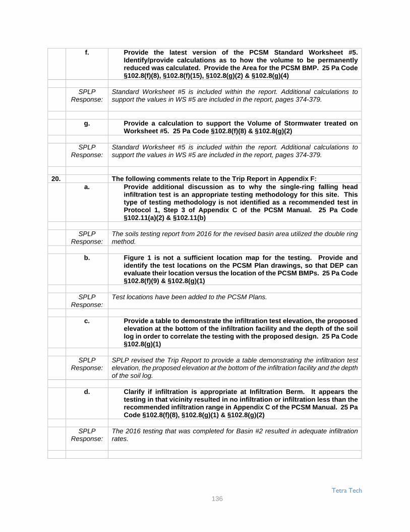
Tetra Tech
136
f. Provide the latest version of the PCSM Standard Worksheet #5.Identify/provide calculations as to how the volume to be permanentlyreduced was calculated. Provide the Area for the PCSM BMP. 25 Pa Code§102.8(f)(8), §102.8(f)(15), §102.8(g)(2) & §102.8(g)(4)
SPLPResponse:
Standard Worksheet #5 is included within the report. Additional calculations tosupport the values in WS #5 are included in the report, pages 374-379.
g. Provide a calculation to support the Volume of Stormwater treated onWorksheet #5. 25 Pa Code §102.8(f)(8) & §102.8(g)(2)
SPLPResponse:
Standard Worksheet #5 is included within the report. Additional calculations tosupport the values in WS #5 are included in the report, pages 374-379.
20. The following comments relate to the Trip Report in Appendix F:a. Provide additional discussion as to why the single-ring falling head
infiltration test is an appropriate testing methodology for this site. Thistype of testing methodology is not identified as a recommended test inProtocol 1, Step 3 of Appendix C of the PCSM Manual. 25 Pa Code§102.11(a)(2) & §102.11(b)
SPLPResponse:
The soils testing report from 2016 for the revised basin area utilized the double ringmethod.
b. Figure 1 is not a sufficient location map for the testing. Provide andidentify the test locations on the PCSM Plan drawings, so that DEP canevaluate their location versus the location of the PCSM BMPs. 25 Pa Code§102.8(f)(9) & §102.8(g)(1)
SPLPResponse:
Test locations have been added to the PCSM Plans.
c. Provide a table to demonstrate the infiltration test elevation, the proposedelevation at the bottom of the infiltration facility and the depth of the soillog in order to correlate the testing with the proposed design. 25 Pa Code§102.8(g)(1)
SPLPResponse:
SPLP revised the Trip Report to provide a table demonstrating the infiltration testelevation, the proposed elevation at the bottom of the infiltration facility and the depthof the soil log.
d. Clarify if infiltration is appropriate at Infiltration Berm. It appears thetesting in that vicinity resulted in no infiltration or infiltration less than therecommended infiltration range in Appendix C of the PCSM Manual. 25 PaCode §102.8(f)(8), §102.8(g)(1) & §102.8(g)(2)
SPLPResponse:
The 2016 testing that was completed for Basin #2 resulted in adequate infiltrationrates.

Tetra Tech
137
21. DEP recommends only providing one copy of the plan drawings perapplication set (do not provide reduced scale drawings after Appendix F in thenarrative), to avoid confusion and potential inconsistencies. 25 Pa Code§102.4(b)(5)(ix)
SPLPResponse:
All reduced sized plans were removed from the Infiltration Testing report.
22. Clarify if the infiltration calculations for the PCSM BMP account the time ofconcentration or 2 hours as the infiltration Period. If the infiltration periodexceeds the time of concentration or 2 hours as recommended in the PCSMManual, provide a discussion of how the proposed infiltration period willachieve the same regulatory standards as the recommendations of the PCSMManual. 25 Pa Code §102.8(f)(8), §102.8(g)(2), §102.11(a)(2) & §102.11(b)
SPLPResponse:
Basin #2 has a surface area of 13,718 square feet at elevation 686.0. Since theorifice is set at elevation 686.25, there is no outflow during the 2 year storm event.An average infiltration rate for the Basin area was found to be 1.75 in/hr (design rate= .875 in/hr). For the 2 year storm event, the PondPack dewatering calculationshows the basin to fully dewater within 38 hours. Please see page 361 of the report.
Page 9323. Identify if a Safety Factor was utilized in the infiltrate rate for design purposes.
If a Safety Factor was utilized, identify the Safety Factor and identify how itwas determined. If a Safety Factor was not utilized, provide discussion as towhy a Safety Factor was not utilized (as recommended on Page 19 of AppendixC of the PCSM Manual). Make all revisions necessary. 25 Pa Code §102.8(f)(8),§102.8(g)(2), §102.8(g)(3), §102.8(g)(4), §102.11(a)(2) & §102.11(b)
SPLPResponse:
A safety factor of “2” was utilized for the infiltration rate, based on the recommendedminimum value allowed in the PA Stormwater BMP Manual.
24. Clarify how the conveyance facilities (i.e. pipes and swales) are designed. Willthey convey the 100 year storm event or was the overflow/bypass accountedfor in the design. Provide conveyance calculations for any stormwaterconveyance features which are critical to the PCSM BMP design. For instanceif the stormwater up to the 100 year storm event is to be managed by a PCSMBMP and the stormwater only reaches the PCSM BMP by being conveyed tothe PCSM BMP through a conveyance feature, calculations demonstrating theconveyance facility can convey the 100-year storm to the PCSM BMP arerequired. The conveyance feature needs to be identified as a PCSM BMP andhave associated Operation and Maintenance. 25 Pa Code §102.8(f)(8) &§102.8(f)(15)
SPLPResponse:
All pipes and swales were sized for the 100 year storm event, since they carry flowsto a PCSM BMP. The O & M schedule was updated to include the swales and pipesas PCSM BMPs. See page 7 of the PCSM plans.
25. Provide procedures which ensure the proper measures for recycling ordisposal of materials associated with or from the PCSM BMPs in accordancewith Department laws, regulations and requirements. 25 Pa Code §102.8(f)(11)

Tetra Tech
138
SPLPResponse:
Please see Inspection and Maintenance of Control Facilities, part 5, for recycling ofconstruction materials. Wherever possible, recycling of excess materials ispreferred, rather than disposal.
26. Provide the proposed loading ratios (total and impervious) and associatedcalculations for each infiltration PCSM BMP. If the loading ratios exceed therecommendations in the PCSM Manual, provide a discussion of how theproposed loading ratios will achieve the same regulatory standards as therecommendations of the PCSM Manual. 25 Pa Code §102.8(f)(15),§102.11(a)(2) & §102.11(b)
SPLPResponse:
The impervious loading ratio of 5:1 is met for the infiltration basin. The actualimpervious/infiltration area ratio is 2:1. The total area/infiltration area is equal to 11:1.In order to meet the ratio for the total drainage area, (8:1) the existing wooded areawest of the house would have to be diverted around the basin. We do not believethis is a prudent solution, since diverting the flow would create additional disturbedareas, remove additional tree cover near the basin and create an additional pointdischarge from a diversion pipe. We believe the PCSM Manual standards have beenexceeded for the revised basin design. See chart 5B in Appendix E page 379 of thereport.
27. Provide a thermal impact analysis for the project. 25 Pa Code §102.8(f)(13)
SPLPResponse:
The thermal impact analysis was added to Section 5.0 of the PCSM Report.
28. Provide Worksheets #1-3 for the project. 25 Pa Code §102.6(a)(1), §102.8(g)(1)& §102.8(g)(2)
SPLPResponse:
Worksheets #1 through #5 are located in Appendix E, Pages 368-372.
29. Provide an analysis to demonstrate the PCSM BMPs will meet the water qualityrequirements (i.e. Worksheet #10 and/or Worksheets #11-13). Refer to theWater Quality Process Flow chart on page 40 in Chapter 8 of the PCSM Manualfor additional information. 25 Pa Code §102.8(g)(2) & §102.11(a)(2)
SPLPResponse:
Worksheet #10 was completed and is located in Appendix E, Page 373.
Page 9430. Clarify if an antidegradation analysis has to be completed. If so, provide an
antidegradation analysis for the PCSM Plan. 25 Pa Code §102.8(d), §102.8(f)(6)& §102.8(h)
SPLPResponse:
An antidegradation analysis was added to the PCSM Report, Section 4.0.
31. Provide additional information/calculations to clarify how the volumes werecalculated for the infiltration basin and berm in Worksheet #5. 25 Pa Code§102.8(f)(8) & §102.8(f)(15)

Tetra Tech
139
SPLPResponse:
Additional volume reduction calculations are provided in the PCSM report, pages374-379.
32. Provide dewatering time calculations of the proposed PCSM BMPs. 25 PaCode §102.8(f)(8) & §102.11(a)(2)
SPLPResponse:
The basin dewatering time calculation is shown in the PCSM report. See AppendixD, Pages 360-366.
PCSM Plan Drawings - Block Valve1. The following technical deficiencies are associated with Sheet PCS-0.01 (for
all Spreads):a. Note 1 appears to indicate that the sites have not been field surveyed for
contour information; which is not adequate for a final design. Provide theexisting topographic features of the project site and immediatesurrounding area. 25 Pa Code §102.8(f)(1) & §102.8(f)(9)
SPLPResponse:
Topographic surveys were performed to generate an accurate site grading plan forthe block valve sites which will minimize cut and fill slopes. The extent of the surveydid not extend through the entire drainage area at each block valve site. Therefore,it would be difficult to show the surveyed topography for only a portion of theanalyzed drainage area because existing grades would not tie in to PASDA Lidarseamlessly. Note 1 has been revised to provide clarification.
b. Note 2 identifies the project as being in Dauphin County. While this ispartially correct, as part of the project is within Dauphin County; providethe full identification of where the project is located. If there are differentplan sets for each Spread, then identify those counties which are coveredby that particular set of drawings for each Spread. 25 Pa Code §102.8(f)(3)& §102.8(f)(9)
SPLPResponse:
Note 2 has been revised to be specific to each Spread.
c. Notes 6, 7 & 11 appear to be related to E&S and not PCSM. The PCSM Planshall be separate from the E&S Plan and the E&S Plan shall be separatefrom the PCSM Plan. Make all revisions necessary. 25 Pa Code§102.4(b)(5)(xiv) & §102.8(d)
SPLPResponse:
Notes 6 and 7 have been removed because they are not applicable. Note 11 hasbeen revised to state that the Site Restoration/Post-Construction StormwaterManagement Plan shall be onsite.
d. The plan set is identified as PCSM; however, a Site Restoration Scheduleand Site Restoration notes are provided. Clarify if this plan set includesany areas covered by site restoration. 25 Pa Code §102.8(f)(3) &§102.8(f)(9)
SPLPResponse:
The site restoration schedule and notes have been removed from the plan set. Thedrawings within the Erosion and Sediment Control Plan address site restoration.
e. The following technical deficiencies are associated with the constructionsequence in Section 3.1 starting on Page 7: 25 Pa Code §102.8(f)(7)

Tetra Tech
140
i. It is identified that "It is not intended that the drawings and this reportshow detailed information on methods and materials." This statementdoes not meet regulations. The E&S and PCSM Plans shall be final forconstruction. Provide the information, details, methods and materialsto properly construct and implement the Plans, including the BMPs,within the construction sequences associated with these Plans. 25 PaCode §102.4(b)(5)(xiv) & §102.8(d)
SPLPResponse:
The referenced statement has been removed from the construction sequence.
Page 95ii. It is identified that the contractor can deviate from the authorized E&S
and PCSM Plans based upon field conditions. A deviation from theauthorized plans may be necessary; however, the appropriate countyconservation district and DEP have to approve any deviation to theauthorized plans. Make all revisions necessary to clearly identify thisrequirement.
SPLPResponse:
Clarification has been added to the construction sequence to specify that theappropriate county conservation district and DEP have to approve any deviation tothe authorized plans.
iii. Provide a schedule of inspections for critical stages of PCSM BMPinstallation with the construction sequence.
SPLPResponse:
An operation and maintenance schedule for the PCSM BMPs has been added tothe plan set.
f. The Long Term Inspections and Maintenance for Site Restoration andPCSM Controls notes are not sufficient. Refer to the technical deficienciesidentified within the corresponding Site Restoration and PCSM Plannarrative and make all revisions necessary. 25 Pa Code §102.8(f)(10)
SPLPResponse:
The long term operation and maintenance section has been revised for consistencywith the edits made throughout the narrative.
2. The following technical deficiencies are associated with Sheet PCS-0.02 (forall Spreads):
a. The notes and information provided on this plan sheet appear to be relatedto E&S Plan and not the Site Restoration and PCSM Plans (the plan sheetin Spread 4 is titled "Erosion & Sediment Control Notes" and the plansheet in Spread 5 is titled "Post Construction Stormwater ManagementPlan Erosion & Sediment Control Notes"). The PCSM Plan shall beseparate from the E&S Plan and the E&S Plan shall be separate from thePCSM Plan. Make all revisions necessary. 25 Pa Code §102.4(b)(5)(xiv) &§102.8(d)
SPLPResponse:
The referenced E&S notes have been removed from the PCSM plan drawings.
3. The following technical deficiencies are associated with Sheet PCS-0.03 (forall Spreads):

Tetra Tech
141
a. Refer to the technical deficiencies identified within the corresponding SiteRestoration and PCSM Plan narrative related to the seeding information andmake all revisions necessary. 25 Pa Code §102.8(f)(6)
SPLPResponse:
The seeding schedule has been revised for consistency within the plan narrative.
4. The following technical deficiencies are associated with Sheet PCS-0.04 (forall Spreads):
a. Identify why details for E&S BMPs have been provided. The PCSM Planshall be separate from the E&S Plan and the E&S Plan shall be separatefrom the PCSM Plan. Make all revisions necessary. 25 Pa Code§102.4(b)(5)(xiv) & §102.8(d)
SPLPResponse:
Details for E&S BMPs have been removed from the drawings because they are notapplicable.
b. Provide a detail or information for the stone/gravel for the sites includedwithin these plan sets. 25 Pa Code §102.8(f)(6)
SPLPResponse:
A detail showing the stone to be used for the block valve sites and associatedpermanent access roads has been added.
Page 96c. The following technical deficiencies are associated with the Soil
Amendment Detail: 25 Pa Code §102.8(f)(6)i. Note 3 identifies that on-site soils with at least 5% organic content can
be a substitute for the compost. Design Consideration 1.e on Page 224in Chapter 6 of the PCSM Manual recommends that on-site soils withan organic content of at least 5% can be properly stockpiled and re-used. Identify if the existing on-site soils have been tested. Identifyhow the on-site soils will be properly stockpiled. Identify that it will bedetermined if the on-site soils have at least a 5% organic content.Identify if the 5% organic content is by weight or by volume. 25 PaCode §102.8(g)(1), §102.11(a)(2) & §102.11(b)
SPLPResponse:
The soil amendment detail has been revised to remove a portion of Note 3 to indicatethat on-site soils will no longer be used as a substitute for compost.
ii. Provide sufficient information to identify how the soil amendments willbe accomplished (by tilling, by excavation, mixing and placement,etc.).
SPLPResponse:
Information has been added to the detail to identify how the soil amendments will beaccomplished.
d. The following technical deficiencies are associated with the InfiltrationBerm Detail: 25 Pa Code §102.8(f)(6)
i. The shape of the berm is not per the recommendations of the PCSMManual. The PCSM Manual recommends that the crest of the berm issmoothly convex, the toes of the berm are smoothly concave and thatthe crest of the bean should be located near the downstream end ofthe berm rather than in the middle. Revise the design or provide therequired information for the alternative BMP and design standard. 25Pa Code §102.11(a)(2) & §102.11(b)

Tetra Tech
142
SPLPResponse:
The shape of the infiltration berm detail has been revised to be consistent with therecommendations of the PADEP PCSM Manual.
ii. Note 1 appears to indicate that all berms will have soil amendments inponded area behind the berms. If that is the case, provide the soilamendment as part of the Infiltration Berm Detail.
SPLPResponse:
Note 1 concerning the use of soil amendments at all infiltration berms has beenremoved.
e. The following technical deficiencies are associated with the InfiltrationTrench Detail: 25 Pa Code §102.8(f)(6)
i. Identify the stone to be used for the trench.
SPLPResponse:
The infiltration trench detail has been updated to show that AASHTO No. 3 stonewill be used for the trench.
ii. Provide additional information related to the nonwoven geotextilefabric (strength, overlap, etc.).
SPLPResponse:
Additional information on the nonwoven geotextitle has been added to the detail.
iii. Identify the required pipe size for the trench; it is not appropriate toidentify a minimum pipe size.
SPLPResponse:
Inspection and maintenance language has been added to the plan drawings.
Page 97iv. Identify how the infiltration trench will be inspected for proper function
and operation, including full dewatering to the bottom of the trench.25 Pa Code §102.8(f)(10)
SPLPResponse:
Additionally, the detail has been revised to show a HDPE cleanout to be installed inthe trench for observation and maintenance.
v. Identify if an infiltration trench proposed for Spread 5. If an infiltrationtrench is not proposed for Spread 5, then remove the detail andinformation related to the trench from the Spread 5 plan set. 25 PaCode §102.8(f)(9)
SPLPResponse:
An infiltration trench is proposed at the Montello site so the infiltration trench detailremain in the Spread 5 plan set.
5. The following technical deficiencies are general technical deficiencies thatappear on most or all of the individual site plan sheets:
a. There is different shading/coloring used on the plan drawings that doesnot match what is provided in the Legend. Provide consistency betweenthe plan drawings and the Legend. 25 Pa Code §102.8(f)(9)
SPLPResponse:
The legend and plan drawings have been revised to be consistent.

Tetra Tech
143
b. The existing contours are lost on the plan views due to theshading/coloring. Provide legible existing contour information. 25 PaCode §102.8(f)(1), §102.8(f)(3) & §102.8(f)(9)
SPLPResponse:
The existing contours have been revised to be clearly visible through theshading/coloring.
c. Provide the ESCGP-2 Permit Boundary, identify the soil types and theirlocations, and provide additional contour labels (existing and proposed).25 Pa Code §102.8(f)(3) & §102.8(f)(9)
SPLPResponse:
The ESCGP-2 permit boundary, soil types and their limits, and additional contourlabels for existing and proposed contours have been added to the plan drawings.
d. Correctly show the grading for the infiltration berms, including the 2 ft.berm height, the 3:1 side slopes and the 2 ft. wide top of berm. Identifyhow runoff will be fully captured behind the berms; without any up-turnsat the end of the berms runoff will flow around the ends and bypass theberms. 25 Pa Code §102.8(f)(3) & §102.8(f)(9)
SPLPResponse:
Grading for the proposed infiltration berms is now provided to be consistent with thedetail.
e. Ensure that all proposed grading is clearly shown, and ensure that allproposed grading ties back into the existing contour lines. 25 Pa Code§102.8(f)(3) & §102.8(f)(9)
SPLPResponse:
Proposed grading has been revised to be clear and to ensure that grading ties inwith existing contour lines.
f. Provide the existing grade in the Section cuts. 25 Pa Code §102.8(f)(1),§102.8(f)(3) & §102.8(f)(9)
SPLPResponse:
Existing grade is now provided in section cuts.
g. Identify how the proposed underdrain will be able to convey the runoff tothe infiltration berm as shown on the plan. It appears that there would besome surface runoff that does not percolate through the stone to theunderdrain, and that there would be flow along the bottom of thestone/gravel pad that could bypass the underdrain all together (especiallyif the underdrain is not installed at the very bottom of the stone/gavel).Provide calculations showing that the underdrain system can convey theentire 100-year/24-hour storm event for each site where it is proposed.Provide additional information for the underdrain detail to ensure that thesystem is properly installed. 25 Pa Code §102.8(b),§102.8(f)(3), §102.8(f)(6), §102.8(f)(8) & §102.8(f)(9)

Tetra Tech
144
SPLPResponse:
Underdrains have been proposed at certain block valve sites where sheet flow fromthe pad will not naturally reach the BMP. The underdrains have been sized toconvey the runoff to the downstream BMP. To enhance functionality of theunderdrain and to increase the conveyance capacity, a diversion berm has beenadded downslope of the underdrain as shown in the revised detail. This diversionberm will capture runoff that does not percolate through the stone and into theunderdrain. The overall slope of the diversion berm follows that of the underdrainso that runoff is conveyed to the same point.
Page 98h. There are numerous sites where the infiltration BMP is proposed directly
or partially over the proposed mainline, which will be backfilled andcompacted as part of the mainline construction. Protocol 2.2.a ofAppendix C of the PCSM Manual recommends against infiltrating in areasof compacted fill. Provide the demonstration that these PCSM BMPs willproperly manage the runoff for the function intended. If therecommendations of the PCSM Manual are not followed, then provide ademonstration which identifies how the alternative BMP and designstandard will achieve the same regulatory standards as therecommendations of the PCSM Manual. 25 Pa Code §102.8(f)(15),§102.8(g)(1), §102.8(g)(2), §102.8(g)(3), §102.11(a)(2) & §102.11(b)
SPLPResponse:
Infiltration BMPs that were previously proposed directly or partially over theproposed mainline as well as existing pipelines have been revaluated and relocatedto avoid ponding on the pipeline locations. Additional infiltration testing, whereneeded, has been taken place for the relocated infiltration BMPs.
i. The ponding area for many of the infiltration berms is shown to be withinthe grading for, and in some instances within, the stone/gravel pad.Protocol 2.2.a of Appendix C of the PCSM Manual recommends againstinfiltrating in areas of compacted fill. Provide the demonstration that thesePCSM BMPs will properly manage the runoff for the function intended. Ifthe recommendations of the PCSM Manual are not followed, then providea demonstration which identifies how the alternative BMP and designstandard will achieve the same regulatory standards as therecommendations of the PCSM Manual. 25 Pa Code §102.8(f)(15),§102.8(g)(1), §102.8(g)(2), §102.8(g)(3), §102.11(a)(2) & §102.11(b)
SPLPResponse:
The locations of the proposed infiltration PCSM BMPs have been revised as to notinfiltrate on compacted fill.
j. Orange construction fence is identified to be installed. Clearly identify thefunction of the orange construction fence. If the function is to protect theponding area during construction, then identify how the stone/gravel siteswill be able to be properly constructed; as the orange construction fenceis shown with the grading and area for the stone/gravel site. 25 Pa Code§102.8(f)(3), §102.8(f)(6), §102.8(f)(7) & §102.8(f)(9)
SPLPResponse:
The orange construction fence to be used on site is no longer shown on the PCSMplan drawings, instead the fence is shown on the E&S plan drawings.
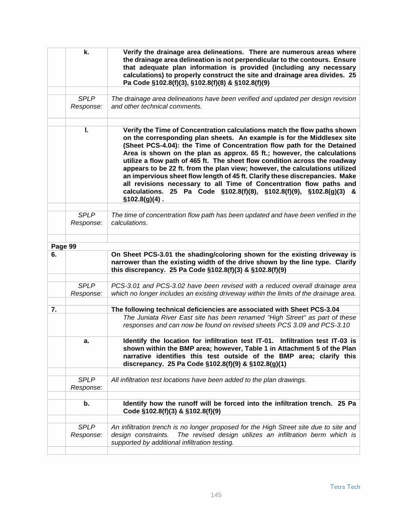
Tetra Tech
145
k. Verify the drainage area delineations. There are numerous areas wherethe drainage area delineation is not perpendicular to the contours. Ensurethat adequate plan information is provided (including any necessarycalculations) to properly construct the site and drainage area divides. 25Pa Code §102.8(f)(3), §102.8(f)(8) & §102.8(f)(9)
SPLPResponse:
The drainage area delineations have been verified and updated per design revisionand other technical comments.
l. Verify the Time of Concentration calculations match the flow paths shownon the corresponding plan sheets. An example is for the Middlesex site(Sheet PCS-4.04): the Time of Concentration flow path for the DetainedArea is shown on the plan as approx. 65 ft.; however, the calculationsutilize a flow path of 465 ft. The sheet flow condition across the roadwayappears to be 22 ft. from the plan view; however, the calculations utilizedan impervious sheet flow length of 45 ft. Clarify these discrepancies. Makeall revisions necessary to all Time of Concentration flow paths andcalculations. 25 Pa Code §102.8(f)(8), §102.8(f)(9), §102.8(g)(3) &§102.8(g)(4) .
SPLPResponse:
The time of concentration flow path has been updated and have been verified in thecalculations.
Page 996. On Sheet PCS-3.01 the shading/coloring shown for the existing driveway is
narrower than the existing width of the drive shown by the line type. Clarifythis discrepancy. 25 Pa Code §102.8(f)(3) & §102.8(f)(9)
SPLPResponse:
PCS-3.01 and PCS-3.02 have been revised with a reduced overall drainage areawhich no longer includes an existing driveway within the limits of the drainage area.
7. The following technical deficiencies are associated with Sheet PCS-3.04The Juniata River East site has been renamed "High Street" as part of theseresponses and can now be found on revised sheets PCS 3.09 and PCS-3.10
a. Identify the location for infiltration test IT-01. Infiltration test IT-03 isshown within the BMP area; however, Table 1 in Attachment 5 of the Plannarrative identifies this test outside of the BMP area; clarify thisdiscrepancy. 25 Pa Code §102.8(f)(9) & §102.8(g)(1)
SPLPResponse:
All infiltration test locations have been added to the plan drawings.
b. Identify how the runoff will be forced into the infiltration trench. 25 PaCode §102.8(f)(3) & §102.8(f)(9)
SPLPResponse:
An infiltration trench is no longer proposed for the High Street site due to site anddesign constraints. The revised design utilizes an infiltration berm which issupported by additional infiltration testing.

Tetra Tech
146
c. Provide an adequate representation of the proposed infiltration trench onSection A-A (including the 6 in minimum soil on top of the stone, theperforated pipe is not shown, etc.). Provide the existing and proposedcontours/grading and the stone/gravel site on Section A-A. 25 Pa Code§102.8(f)(3), §102.8(f)(6) & §102.8(f)(9)
SPLPResponse:
An infiltration trench is no longer proposed for the High Street site due to site anddesign constraints. The revised design utilizes an infiltration berm which issupported by additional infiltration testing.
d. The limits of the infiltration trench are difficult to discern. Properly identifythe limits of the infiltration trench, including the required trench length. 25Pa Code §102.8(f)(3), §102.8(f)(6) & §102.8(f)(9)
SPLPResponse:
An infiltration trench is no longer proposed for the High Street site due to site anddesign constraints. The revised design utilizes an infiltration berm which issupported by additional infiltration testing.
e. Based upon the contour information, it appears that the infiltration trenchwill constructed with a top elevation that varies. Identify if the infiltrationtrench's bottom will be constructed at a constant elevation (if so, identifythat elevation). If the infiltration trench will be constructed with a slopingbottom, ensure that any and all calculations for the trench properlyaccount for the sloping bottom (i.e. reduced capacity). 25 Pa Code§102.8(f)(3), §102.8(f)(6), §102.8(f)(8) & §102.8(f)(9)
SPLPResponse:
An infiltration trench is no longer proposed for the High Street site due to site anddesign constraints. The revised design utilizes an infiltration berm which issupported by additional infiltration testing.
f. Identify the existing PennDOT right-of-way. 25 Pa Code §102.8(f)(9)
SPLPResponse:
The existing road right-of-way has been added to the plan drawings.
8. The following technical deficiencies are associated with Sheet PCS-3.05The Raystown Road site is not shown on plan drawings PCS-3.11 and PCS-3.12
a. The top of berm is identified as 822.90; however, a contour line forelevation 823 is shown at the top of the berm. Clarify this discrepancy. 25Pa Code §102.8(f)(9)
SPLPResponse:
The proposed berm top elevations have been corrected to show the correctelevations labeled.
b. Identify the existing PennDOT right-of-way. 25 Pa Code §102.8(f)(9)
SPLPResponse:
The existing road right-of-way has been added to the plan drawings.
Page 1009. The following technical deficiencies are associated with Sheet PCS-3.06
The Raystown Lake West site has been renamed "Seven Points Loop" as a partof these responses. The site can now be found on sheet PCS-3.13

Tetra Tech
147
a. It appears that the flow direction arrow for SM54 is backwards. Clarify thisdiscrepancy. 25 Pa Code §102.8(f)(9)
SPLPResponse:
As a result of the redesign and resheeting, S-M54 no longer appears on the plandrawing.
b. Identify the hatching shown at the POI and the receiving surface water. 25Pa Code §102.8(f)(9)
SPLPResponse:
As surrounding drainage area for the purposes of PCSM calculations is no longershown as the site will be in meadow post condition with no proposed impervioussurfaces.
10. Based upon the existing and proposed contours on Sheet PCS-3.07, thedrainage area delineation and Time of Concentration flow path for theDetained Area are not shown correctly. As it appears that the runoff would bedirected towards the road and not across the stone/gravel site and down theembankment to the BMP. Clarify this discrepancy. 25 Pa Code §102.8(f)(9)
SPLPResponse:
The Raystown Lake East Site Has been renamed "Happy Hills Road" as part ofthese responses. This site can now be found on sheets PCS-3.1 4 and PCS-3.15.A water deflector has been added to the proposed driveway to divert flow downslopeto the PCSM BMP and to prevent runoff from flowing towards Happy Hills Road.
11. Identify if the waterbars shown on Sheet P.CS-3.08 are permanent and willremain after construction. If the waterbars are permanent and will remain,then properly account for them in the drainage area delineations and the Timeof Concentration flow paths. Make all revisions necessary. 25 Pa Code§102.8(f)(3), §102.8(f)(8) & §102.8(f)(9)
SPLPResponse:
The PA 655 site has been renamed "Hares Valley Road" as part of these responsesand can now be found on sheets PCS-3.16 and 3.17
12. The following technical deficiencies are associated with Sheet PCS-3.09a. Clarify why the proposed stone drive for the site is not shown connecting
to the existing drive. 25 Pa Code §102.8(f)(3) & §102.8(f)(9)
SPLPResponse:
The design for the Shade Valley Road block valve site has been modified. With thisnew design, the proposed gravel access road is shown connecting to the existingdriveway.
b. Correct the overlapping text. 25 Pa Code §102.8(f)(9)
SPLPResponse:
The overlapping text has been corrected.
13. The following technical deficiencies are associated with Sheet PCS-4.01The Plainfield block valve site will now be collocated with the pump station in aneffort to minimize the addition of impervious cover to the maximum extentpracticable. The valve settings will fit within the existing footprint of the Plainfieldpump station. The limit of disturbance has been revised in this area toaccommodate the revision. As a result of these changes, the commentsregarding post-construction stormwater management at the Plainfield blockvalve site no longer apply.

Tetra Tech
148
a. The top of berm is labeled as 563.00; however, a contour line for elevation568 is shown at the top of the berm. Clarify this discrepancy. 25 Pa Code§102.8(f)(9)
SPLPResponse:
The Plainfield block valve site will now be collocated with the pump station in aneffort to minimize the addition of impervious cover to the maximum extentpracticable. The valve settings will fit within the existing footprint of the Plainfieldpump station. The limit of disturbance has been revised in this area to accommodatethe revision. As a result of these changes, the comments regarding post-construction stormwater management at the Plainfield block valve site no longerapply.
b. Identify if infiltration testing and soil probes were performed for InfiltrationBerm A. 25 Pa Code §102.8(f)(9) & §102.8(g)(1)
SPLPResponse:
The Plainfield block valve site will now be collocated with the pump station in aneffort to minimize the addition of impervious cover to the maximum extentpracticable. The valve settings will fit within the existing footprint of the Plainfieldpump station. The limit of disturbance has been revised in this area to accommodatethe revision. As a result of these changes, the comments regarding post-construction stormwater management at the Plainfield block valve site no longerapply.
c. It appears that the Infiltration Berms have separate points of discharge toa receiving surface water; however, the runoff rate calculations wereperformed for a single point of interest. Clarify this discrepancy. 25 PaCode §102.8(f)(4), §102.8(f)(8), §102.8(f)(9), §102.8(g)(3) & §102.8(g)(4)
SPLPResponse:
The Plainfield block valve site will now be collocated with the pump station in aneffort to minimize the addition of impervious cover to the maximum extentpracticable. The valve settings will fit within the existing footprint of the Plainfieldpump station. The limit of disturbance has been revised in this area to accommodatethe revision. As a result of these changes, the comments regarding post-construction stormwater management at the Plainfield block valve site no longerapply.
Page 10114. The following technical deficiencies are associated with Sheet PCS-4.02
a. The grading for the infiltration berm does not show the top elevation of434.00. 25 Pa Code §102.8(f)(9)
SPLPResponse:
Due to site constraints associated with the previously proposed site, the Creek Roadsite has been relocated as a part of these responses. The limit of disturbance hasbeen revised in this area to accommodate the revision. Additional infiltration testingwas performed on the newly proposed location and the PCSM design has beenupdated to address the appropriate stormwater requirements. Plan drawings canbe found on sheets PCS-4.01 and PCS-4.02
b. It appears that the infiltration testing for the infiltration berm is not locatednear the berm's proposed location. Provide the demonstration that thistesting is an adequate predevelopment site characterization andassessment of soil and geology for the proposed PCSM BMP. 25 Pa Code§102.8(f)(9) & §102.8(g)(1)
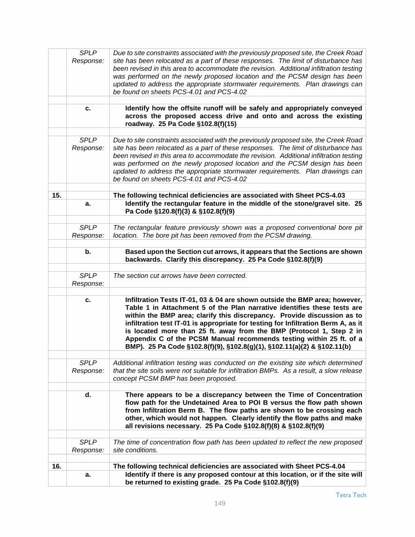
Tetra Tech
149
SPLPResponse:
Due to site constraints associated with the previously proposed site, the Creek Roadsite has been relocated as a part of these responses. The limit of disturbance hasbeen revised in this area to accommodate the revision. Additional infiltration testingwas performed on the newly proposed location and the PCSM design has beenupdated to address the appropriate stormwater requirements. Plan drawings canbe found on sheets PCS-4.01 and PCS-4.02
c. Identify how the offsite runoff will be safely and appropriately conveyedacross the proposed access drive and onto and across the existingroadway. 25 Pa Code §102.8(f)(15)
SPLPResponse:
Due to site constraints associated with the previously proposed site, the Creek Roadsite has been relocated as a part of these responses. The limit of disturbance hasbeen revised in this area to accommodate the revision. Additional infiltration testingwas performed on the newly proposed location and the PCSM design has beenupdated to address the appropriate stormwater requirements. Plan drawings canbe found on sheets PCS-4.01 and PCS-4.02
15. The following technical deficiencies are associated with Sheet PCS-4.03a. Identify the rectangular feature in the middle of the stone/gravel site. 25
Pa Code §120.8(f)(3) & §102.8(f)(9)
SPLPResponse:
The rectangular feature previously shown was a proposed conventional bore pitlocation. The bore pit has been removed from the PCSM drawing.
b. Based upon the Section cut arrows, it appears that the Sections are shownbackwards. Clarify this discrepancy. 25 Pa Code §102.8(f)(9)
SPLPResponse:
The section cut arrows have been corrected.
c. Infiltration Tests IT-01, 03 & 04 are shown outside the BMP area; however,Table 1 in Attachment 5 of the Plan narrative identifies these tests arewithin the BMP area; clarify this discrepancy. Provide discussion as toinfiltration test IT-01 is appropriate for testing for Infiltration Berm A, as itis located more than 25 ft. away from the BMP (Protocol 1, Step 2 inAppendix C of the PCSM Manual recommends testing within 25 ft. of aBMP). 25 Pa Code §102.8(f)(9), §102.8(g)(1), §102.11(a)(2) & §102.11(b)
SPLPResponse:
Additional infiltration testing was conducted on the existing site which determinedthat the site soils were not suitable for infiltration BMPs. As a result, a slow releaseconcept PCSM BMP has been proposed.
d. There appears to be a discrepancy between the Time of Concentrationflow path for the Undetained Area to POI B versus the flow path shownfrom Infiltration Berm B. The flow paths are shown to be crossing eachother, which would not happen. Clearly identify the flow paths and makeall revisions necessary. 25 Pa Code §102.8(f)(8) & §102.8(f)(9)
SPLPResponse:
The time of concentration flow path has been updated to reflect the new proposedsite conditions.
16. The following technical deficiencies are associated with Sheet PCS-4.04a. Identify if there is any proposed contour at this location, or if the site will
be returned to existing grade. 25 Pa Code §102.8(f)(9)

Tetra Tech
150
SPLPResponse:
The Middlesex site has been renamed "W. Trindle Road" as part of these responsesand can be found on sheets PCS-4.05and PCS-4.06.
Page 102b. Identify how the runoff will be forced into the infiltration trench. 25 Pa
Code §102.8(f)(3) & §102.8(f)(9)
SPLPResponse:
Runoff along the proposed access road will be directed to the infiltration trench usinga diversion berm. Similarly, runoff from the proposed pad area will also be directedto the infiltration trench and berm using a diversion berm.
c. Provide an adequate representation of the proposed infiltration trench onSection A-A (including the 6 in. minimum soil on top of the stone, theperforated pipe is not shown, etc.). Provide the existing and proposedcontours/grading and the stone/gravel site on Section A-A. 25 Pa Code§102.8(f)(3), §102.8(f)(6) & §102.8(f)(9)
SPLPResponse:
The infiltration trench section and detail have been updated to show an adequaterepresentation of the proposed fence including the minimum soil on top of the stone,the perforated pipe, and other details. The section has been updated to showexisting grade.
d. The limits of the infiltration trench are difficult to discern. Properly identifythe limits of the infiltration trench, including the required trench length. 25Pa Code §102.8(f)(3), §102.8(f)(6) & §102.8(f)(9)
SPLPResponse:
The limits of the infiltration trench have been clarified.
e. Identify if the infiltration trench's bottom will be constructed at a constantelevation (if so, identify that elevation). If the infiltration trench will beconstructed with a sloping bottom, ensure that any and all calculations forthe trench properly account for the sloping bottom (i.e. reduced capacity).25 Pa Code §102.8(f)(3), §102.8(f)(6), §102.8(f)(8) & §102.8(f)(9)
SPLPResponse:
The proposed infiltration trenches will be constructed with a constant elevationtrench bottom.
17. The following technical deficiencies are associated with Sheet PCS-4.05The Arcona Road site can now be found on sheets PCS-4.07 and PCS-08.
a. It appears that the proposed contours are lost due to the shading/coloring.Clarify this discrepancy. 25 Pa Code §102.8(f)(9)
SPLPResponse:
The proposed contours have been revised to be clearly visible through theshading/coloring.
b. Clearly identify the extents of the existing drive, as it is difficult to discernwhat is existing versus what is proposed. 25 Pa Code §102.8(f)(3) &§102.8(f)(9)
SPLPResponse:
The extents of the existing driveway have been clarified.

Tetra Tech
151
18. The following technical deficiencies are associated with Sheet PCS-4.06The Old York site can now be found on sheet PCS-4.09.
a. Identify the infiltration test and soil probe locations. 25 Pa Code§102.8(f)(9) & §102.8(g)(1)
SPLPResponse:
All infiltration test locations have been added to the plan drawings.
b. Identify if the waterbars shown are permanent and to remain afterconstruction. If the waterbars are permanent and will remain, thenproperly account for them in the drainage area delineations and the Timeof Concentration flow paths. Make all revisions necessary. 25 Pa Code§102.8(f)(3), §102.8(f)(8) & §102.8(f)(9)
SPLPResponse:
The permanent waterbars that will remain after construction are now shown on theplan drawings.
19. The following technical deficiencies are associated with Sheet PCS-4.06The Middletown Junction site has been renamed "N. Union Street" as part ofthese responses and can now be found on sheets PCS-4.10 and PCS-4.11.
a. Provide the drainage area delineation between POIs A & B. 25 Pa Code§102.8(f)(9)
SPLPResponse:
The drainage area delineation between the two POIs are now shown.
Page 103b. Identify if the GEOWEB drive is accounted for in the detained drainage
area to Infiltration Berm A or in the undetained drainage area to POI A. Ifthe GEOWEB drive is included in the detained drainage area to InfiltrationBerm A, then provide a demonstration of how the runoff is conveyed tothe BMP. 25 Pa Code §102.8(f)(3), §102.8(f)(8) & §102.8(f)(9)
SPLPResponse:
The use of GEOWEB is no longer proposed for this location.
20. The following technical deficiencies are associated with Sheet PCS-5.01a. Identify the location for infiltration tests IT-01, 02 & 03. 25 Pa Code
§102.8(f)(9) & §102.8(g)(1)
SPLPResponse:
The locations of infiltration tests IT-01, 02, and 03 have been added to the plandrawings.
b. Correctly identify the drainage area divide between Snitz Creek -Quittapahilla Creek & Hammer Creek, as the line shown does not align withthe contour information provided. 25 Pa Code §102.8(f)(9)
SPLPResponse:
The drainage area divide between Snitz Creek - Quittapahilla Creek and HammerCreek has been revised to be correctly identified.
c. Correct the spelling of Quittapahilla Creek. 25 Pa Code §102.8(f)(9)
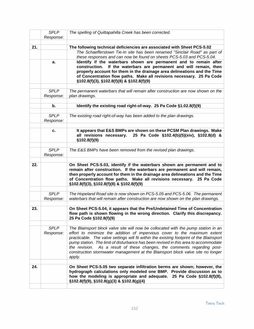
Tetra Tech
152
SPLPResponse:
The spelling of Quittapahilla Creek has been corrected.
21. The following technical deficiencies are associated with Sheet PCS-5.02The Schaefferstown Tie-In site has been renamed "Sinclair Road" as part ofthese responses and can now be found on sheets PCS-5.03 and PCS-5.04.
a. Identify if the waterbars shown are permanent and to remain afterconstruction. If the waterbars are permanent and will remain, thenproperly account for them in the drainage area delineations and the Timeof Concentration flow paths. Make all revisions necessary. 25 Pa Code§102.8(f)(3), §102.8(f)(8) & §102.8(f)(9)
SPLPResponse:
The permanent waterbars that will remain after construction are now shown on theplan drawings.
b. Identify the existing road right-of-way. 25 Pa Code §1.02.8(f)(9)
SPLPResponse:
The existing road right-of-way has been added to the plan drawings.
c. It appears that E&S BMPs are shown on these PCSM Plan drawings. Makeall revisions necessary. 25 Pa Code §102.4(b)(5)(xiv), §102.8(d) &§102.8(f)(9)
SPLPResponse:
The E&S BMPs have been removed from the revised plan drawings.
22. On Sheet PCS-5.03, identify if the waterbars shown are permanent and toremain after construction. If the waterbars are permanent and will remain,then properly account for them in the drainage area delineations and the Timeof Concentration flow paths. Make all revisions necessary. 25 Pa Code§102.8(f)(3), §102.8(f)(8) & §102.8(f)(9)
SPLPResponse:
The Hopeland Road site is now shown on PCS-5.05 and PCS-5.06. The permanentwaterbars that will remain after construction are now shown on the plan drawings.
23. On Sheet PCS-5.04, it appears that the Pre/Undetained Time of Concentrationflow path is shown flowing in the wrong direction. Clarify this discrepancy.25 Pa Code §102.8(f)(9)
SPLPResponse:
The Blainsport block valve site will now be collocated with the pump station in aneffort to minimize the addition of impervious cover to the maximum extentpracticable. The valve settings will fit within the existing footprint of the Blainsportpump station. The limit of disturbance has been revised in this area to accommodatethe revision. As a result of these changes, the comments regarding post-construction stormwater management at the Blainsport block valve site no longerapply.
24. On Sheet PCS-5.05 two separate infiltration berms are shown; however, thehydrograph calculations only modeled one BMP. Provide discussion as tohow the modeling is appropriate and adequate. 25 Pa Code §102.8(f)(8),§102.8(f)(9), §102.8(g)(3) & §102.8(g)(4)

Tetra Tech
153
SPLPResponse:
Sheet PCS-5.05 was originally for the Montello block valve site. This site is nowlocated on sheets PCS-5.07 and PCS-5.08. The site now has two berms and aninfiltration trench. All three BMPs have been modeled separately using Hydraflow.
Page 10425. The following technical deficiencies are associated with Sheet PCS-5.06
The Wyomissing block valve site, which was previously located on sheet PCS-5.06, is now located on sheet PCS-5.09.
a. Identify the locations for infiltration tests. 25 Pa Code §102.8(f)(9) &§102.8(g)(1)
SPLPResponse:
Infiltration test locations have been added to the plan sheet.
b. Identify the existing road right-of-way. 25 Pa Code §102.8(f)(9)
SPLPResponse:
The existing road right-of-way has been added to the plan drawings.
c. Identify how the channelized runoff from the proposed drive will be safelyand appropriately conveyed onto and along the existing roadway. 25 PaCode §102.8(f)(15)
SPLPResponse:
The Wyomissing block valve site is now proposed to be vegetated. Therefore, therewill no longer be channelized runoff from the proposed drive.
PCSM Drawings Mount Union Valves1. The Note on the Cover Sheet refers to a Geotechnical Report which is being
prepared separately from the PCSM Plan and that the certifying engineer forthe PCSM Plan does not certify the geotechnical features. Identify how thisnote meets the regulatory requirements for the PCSM Plan. Identify whatinformation is contained in this additional geotechnical report and identifyhow this other report affects the design and planning of the PCSM Plan. 25Pa Code §102.8(f)(2), §102.8(f)(12), §102.8(g)(1) & §102.8(g)(5)
SPLPResponse:
The additional geotechnical report was prepared for the design of foundations at thefacility. The report also provides information related to embankment fill and slopeconstruction. The note is not intended to meet any specific regulatory requirementsfor the E&S Plan. The note on the plan is included to clarify that the foundations,embankment fill and slope construction are not certified by the PCSM / E&Sengineer. Please reference Section 2.2 Geology and Soils and Attachment 4 for thetypes, depths, slopes, locations, and limitations of the soils present at the site
2. The following technical deficiencies are associated with Sheet C-1:a. Notes 1, 4 & 6 make it appear that the existing site has not been field
surveyed for existing conditions and existing contour/grades. Clarify ifthe existing conditions shown on the plan are field survey. If they are not,identify how the information shown meets the regulatory requirements. 25Pa Code §102.8(f)(1), §102.8(f)(3) & §102.8(f)(9)
SPLPResponse:
The drawing notes were clarified as follows: "1. Existing topography and featurescompiled from www.pasda.psu.edu and Trico Surveying and Mapping, Inc. 2.Property lines from Trico Surveying and Mapping, Inc."
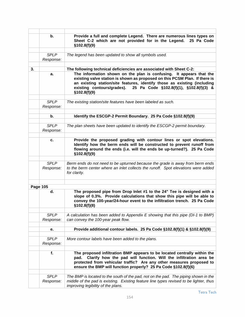
Tetra Tech
154
b. Provide a full and complete Legend. There are numerous lines types onSheet C-2 which are not provided for in the Legend. 25 Pa Code§102.8(f)(9)
SPLPResponse:
The legend has been updated to show all symbols used.
3. The following technical deficiencies are associated with Sheet C-2:a. The information shown on the plan is confusing. It appears that the
existing valve station is shown as proposed on this PCSM Plan. If there isan existing station/site features, identify those as existing (includingexisting contours/grades). 25 Pa Code §102.8(f)(1), §102.8(f)(3) &§102.8(f)(9)
SPLPResponse:
The existing station/site features have been labeled as such.
b. Identify the ESCGP-2 Permit Boundary. 25 Pa Code §102.8(f)(9)
SPLPResponse:
The plan sheets have been updated to identify the ESCGP-2 permit boundary.
c. Provide the proposed grading with contour lines or spot elevations.Identify how the berm ends will be constructed to prevent runoff fromflowing around the ends (i.e. will the ends be up-turned?). 25 Pa Code§102.8(f)(9)
SPLPResponse:
Berm ends do not need to be upturned because the grade is away from berm endsto the berm center where an inlet collects the runoff. Spot elevations were addedfor clarity.
Page 105d. The proposed pipe from Drop Inlet #1 to the 24" Tee is designed with a
slope of 0.3%. Provide calculations that show this pipe will be able toconvey the 100-year/24-hour event to the infiltration trench. 25 Pa Code§102.8(f)(8)
SPLPResponse:
A calculation has been added to Appendix E showing that this pipe (DI-1 to BMP)can convey the 100-year peak flow.
e. Provide additional contour labels. 25 Pa Code §102.8(f)(1) & §102.8(f)(9)
SPLPResponse:
More contour labels have been added to the plans.
f. The proposed infiltration BMP appears to be located centrally within thepad. Clarify how the pad will function. Will the infiltration area beprotected from vehicular traffic? Are any other measures proposed toensure the BMP will function properly? 25 Pa Code §102.8(f)(6)
SPLPResponse:
The BMP is located to the south of the pad, not on the pad. The piping shown in themiddle of the pad is existing. Existing feature line types revised to be lighter, thusimproving legibility of the plans.

Tetra Tech
155
4. The following technical deficiencies are associated with Sheet C-3:a. If the infiltration trench will be constructed with AASHTO #57 stone on top
of the AASHTO #57 stone for the trench (as shown on Infiltration Filter-Section C), then identify the cap of AASHTO #57 with a different style ofhatching that the undisturbed soil below and to the sides of the trench.Make all revisions necessary to accurately and consistently identify howthe infiltration trench will be constructed. 25 Pa Code §102.8(f)(6) &§102.8(f)(9)
SPLPResponse:
The details were revised to clarify how to construct the BMP on sheet C-3 and sheetC-4 of the PCSM Plan.
b. The Berm Detail identifies a height of 2 ft.; however, Section 4.3 on Page15 of the PCSM Plan narrative identifies the height as 1 ft. Clarify thisdiscrepancy and make all revisions necessary. 25 Pa Code §102.8(f)(6) &§102.8(f)(9)
SPLPResponse:
The text in section 4.3 of the PCSM Plan was corrected to indicate a 2 foot berm.
c. The Drop Inlet Detail shows that there will be a sump condition created bythe PVC Drain Basin. Identify how this area was designed or will bemanaged to avoid a condition of continuous standing water in the sump.25 Pa Code §102.8(f)(6), §102.8(f)(9) & §102.8(f)(15)
SPLPResponse:
The sump is considered beneficial in that it provides pretreatment for the BMP byremoving grit and sediment for smaller storm events. The sump will be checked aspart of the routine maintenance schedule and sediment removed as necessary.
d. The details for the infiltration trench are not sufficient to be able toconstruct the BMP. Provide additional detail information, including thenecessary manifolds, fittings, etc. Ensure that all pipe joints are identifiedto be water tight. 25 Pa Code §102.8(f)(6), §102.8(f)(9) & §102.8(f)(15)
SPLPResponse:
More details were added to the plans to clarify how stormwater BMPs will beinstalled.
e. Identify how the infiltration trench will be inspected to ensure that it isproperly and completely dewatering. The Cleanout Detail can only beinspected to the bottom of the perforated pipe. Provide a way to inspectthe bottom of the infiltration trench to ensure proper dewatering. 25 PaCode §102.8(f)(6), §102.8(f)(9) & §102.8(f)(10)
SPLPResponse:
The lowest outlet of the BMP is a 6 inch orifice at elevation 603.00'. The bottom ofthe BMP is at elevation 601.00'. The cleanout can be inspected to an elevation of601.50' An observation of the water level over time between elevation 603.00' and601.50' can provide an accurate estimate of the functional infiltration rate. It can besafely assumed that if the BMP is dewatering properly between elevations 603.00'and 601.50', the BMP will dewater properly to elevation 601.00'.

Tetra Tech
156
Page 106f. The following technical deficiencies are related to the Manhole Detail: 25
Pa Code §102.8(f)(6) & §102.8(f)(9)i. Identify the cover elevation.
SPLPResponse:
Top of grate elevations were added to the inlet callouts on sheet C-2 of the PCSMdrawings.
ii. Identify how the weir structure will be constructed, including how itwill be attached and sealed to the inside of the manhole and of whatmaterial the weir structure is to be made.
SPLPResponse:
The following note has been added to the plan: “The weir structure shall beconstructed of the same material as the PVC drain basin and shall be pre-orderedas installed by the manufacturer.”
PCSM Drawings Doylesburg Station1. The Note on the Cover Sheet refers to a Geotechnical Report which is being
prepared separately from the PCSM Plan and that the certifying engineer forthe PCSM Plan does not certify the geotechnical features. Identify how thisnote meets the regulatory requirements for the PCSM Plan. Identify whatinformation is contained in this additional geotechnical report and identifyhow this other report affects the design and planning of the PCSM Plan. 25Pa Code §102.8(F)(2), §102.8(F)(12), 102.8(g)(1) & 102.8(g)(5)
SPLPResponse:
The additional geotechnical report was prepared for the design of foundations at thefacility. The report also provides information related to embankment fill and slopeconstruction. The note is not intended to meet any specific regulatory requirementsfor the E&S Plan. The note on the plan is included to clarify that the foundations,embankment fill and slope construction are not certified by the PCSM / E&Sengineer. Please reference Section 2.2 Geology and Soils and Attachment 4 for thetypes, depths, slopes, locations, and limitations of the soils present at the site.
2. On Sheet C-1, provide a full and complete Legend. There are numerous linestypes on Sheet C-2 which are not provided for in the Legend. 25 Pa Code§102.8(f)(9)
SPLPResponse:
The legend has been updated to show all symbols used.
3. The following technical deficiencies are associated with Sheet C-2:a. The information shown on the plan is confusing. It appears that the
existing valve station is shown as proposed on this PCSM Plan. If there isan existing station/site features, identify those as existing (includingexisting contours/grades). 25 Pa Code §102.8(f)(1), §102.8(f)(3) &102.8(f)(9)
SPLPResponse:
An existing plan sheet has been added and existing features have been made to berepresented by a grey line for clarity.
b. Identify the ESCGP-2 Penult Boundary. 25 Pa Code §102.8(f)(9)
SPLPResponse:
The PCSM Plan drawings have been updated to show the ESCGP-2 permitboundary.
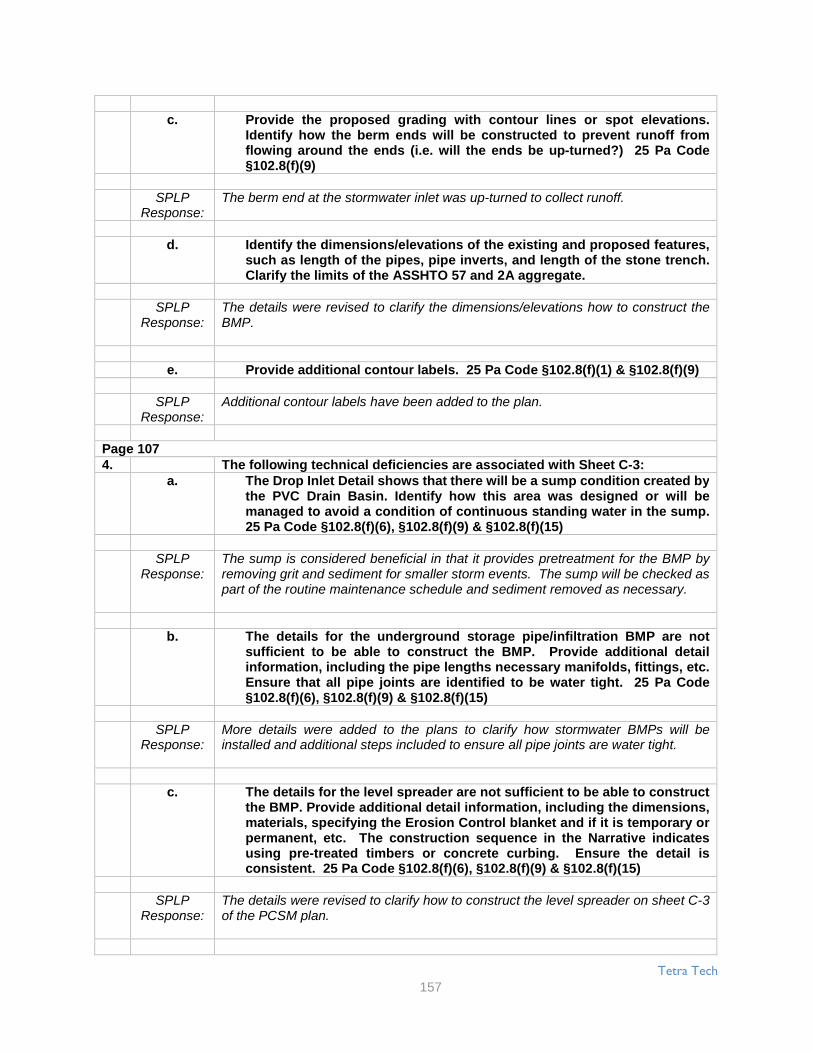
Tetra Tech
157
c. Provide the proposed grading with contour lines or spot elevations.Identify how the berm ends will be constructed to prevent runoff fromflowing around the ends (i.e. will the ends be up-turned?) 25 Pa Code§102.8(f)(9)
SPLPResponse:
The berm end at the stormwater inlet was up-turned to collect runoff.
d. Identify the dimensions/elevations of the existing and proposed features,such as length of the pipes, pipe inverts, and length of the stone trench.Clarify the limits of the ASSHTO 57 and 2A aggregate.
SPLPResponse:
The details were revised to clarify the dimensions/elevations how to construct theBMP.
e. Provide additional contour labels. 25 Pa Code §102.8(f)(1) & §102.8(f)(9)
SPLPResponse:
Additional contour labels have been added to the plan.
Page 1074. The following technical deficiencies are associated with Sheet C-3:
a. The Drop Inlet Detail shows that there will be a sump condition created bythe PVC Drain Basin. Identify how this area was designed or will bemanaged to avoid a condition of continuous standing water in the sump.25 Pa Code §102.8(f)(6), §102.8(f)(9) & §102.8(f)(15)
SPLPResponse:
The sump is considered beneficial in that it provides pretreatment for the BMP byremoving grit and sediment for smaller storm events. The sump will be checked aspart of the routine maintenance schedule and sediment removed as necessary.
b. The details for the underground storage pipe/infiltration BMP are notsufficient to be able to construct the BMP. Provide additional detailinformation, including the pipe lengths necessary manifolds, fittings, etc.Ensure that all pipe joints are identified to be water tight. 25 Pa Code§102.8(f)(6), §102.8(f)(9) & §102.8(f)(15)
SPLPResponse:
More details were added to the plans to clarify how stormwater BMPs will beinstalled and additional steps included to ensure all pipe joints are water tight.
c. The details for the level spreader are not sufficient to be able to constructthe BMP. Provide additional detail information, including the dimensions,materials, specifying the Erosion Control blanket and if it is temporary orpermanent, etc. The construction sequence in the Narrative indicatesusing pre-treated timbers or concrete curbing. Ensure the detail isconsistent. 25 Pa Code §102.8(f)(6), §102.8(f)(9) & §102.8(f)(15)
SPLPResponse:
The details were revised to clarify how to construct the level spreader on sheet C-3of the PCSM plan.

Tetra Tech
158
d. The channel detail indicates both channel have a bottom width of 0 feet,but the contours on the plan show a bottom width. Clarify thediscrepancy. 25 Pa Code §102.8(f)(6), §102.8(f)(9) & §102.8(f)(15)
SPLPResponse:
The channel contours have been revised. The grading for Channel A flares out nearthe end of the channel into a wider bottom, but the analysis was done moreconservatively using a bottom width of 0.
e. Identify how the infiltration BMP will be inspected to ensure that it isproperly and completely dewatering. The Cleanout Detail can only beinspected to the bottom of the perforated pipe. Provide a way to inspectthe bottom of the infiltration trench to ensure proper dewatering. 25 PaCode §102.8(f)(6), §102.8(f)(9) & §102.8(f)(10)
SPLPResponse:
The lowest outlet of the BMP is a 6 inch orifice at elevation 926.00'. The bottom ofthe BMP is at elevation 925.00'. The cleanout can be inspected to an elevation of925.50' An observation of the water level over time between elevation 926.00' and925.50' can provide an accurate estimate of the functional infiltration rate. It can besafely assumed that if the BMP is dewatering properly between elevations 926.00'and 925.50', the BMP will dewater properly to elevation 925.00'. In addition, theunderdrain can be observed at the outlet to determine if it is functioning properly.
f. The following technical deficiencies are related to the Manhole Detail: 25Pa Code §102.8(f)(6) & §102.8(f)(9)
i. Identify the cover elevation.
SPLPResponse:
Top of grate elevations were added to the inlet callouts on sheet C-2 of the PCSMdrawings.
ii. Identify how the weir structure will be constructed, including how itwill be attached and sealed to the inside of the manhole and of whatmaterial the weir structure is to be.
SPLPResponse:
The following note was added to the plan: “The weir structure shall be constructedof the same material as the PVC drain basin and shall be pre-ordered installed bythe manufacturer.”
PCSM Drawings Middletown Pump Station1. Provide a full and complete Legend. There are numerous lines types shown
which are not identified or provided for in the Legend. 25 Pa Code §102.8(f)(9)
SPLPResponse:
The legend has been revised to show all symbols used.
Page 1082. Identify the ESCGP-2 Permit Boundary. 25 Pa Code §102.8(f)(9)
SPLPResponse:
The ESCGP-2 permit boundary has been added.
3. On Sheet 2, expand on the proposed construction techniques or specialconsiderations to address the limitation of piping. Ensure all stormwaterinlets and pipes are watertight. 25 Pa Code §102.8(f)(2) & §102.8(g)(5)

Tetra Tech
159
SPLPResponse:
The soil limitations resolutions have been expanded to include soil piping. All stormpipes are backfilled with select material, and all proposed storm pipes will havewatertight connections. All pipe to inlet connections will also be grouted to remainwatertight. Embankments for the detention basin will be compacted to 95% density.See Sheet 2 notes on the PCSM Plans for additional information.
4. On Sheet 5, the plan and table indicate the top rim of the basin outlet is at anelevation of 342.00, however, the detail on Sheet 8 indicates a top elevation of340. Clarify the discrepancy and ensure the plans are consistent with thecalculations. 25 Pa Code §102.8(f)(8) & §102.8(f)(9)
SPLPResponse:
The detail on Sheet 8 has been corrected. The pipe table on Sheet 5 has beenrevised.
5. On Sheet 5, in the Proposed Storm Pipe Table, clarify Inlet 3 top of gradeelevation. 25 Pa Code §102.8(f)(8) & §102.8(f)(9)
SPLPResponse:
The pipe table on Sheet 5 has been revised.
6. On Sheet 3, clarify the symbol shown on the plans, which are located at theend of diversion channel #1 and at the end of diversion channel #4. Ensure toprovide associated details, if applicable. 25 Pa Code §102.8(f)(6) & §102.8(f)(9)
SPLPResponse:
The symbol is an earthen level lip spreader. The symbol was added to the legendon Sheet 1.
7. Diversion Channels 2-3 are directed into the Infiltration Berm#1. Are thediversion channels supposed to be directed to the infiltration bean or divertedaround the project site? The drainage area to the infiltration berm is not clear,so it cannot be confirmed if these contributing areas were included in theBerm analysis. Clarify the function of the diversion channels. 25 Pa Code§102.8(f)(4) & §102.8(f)(6)
SPLPResponse:
The Infiltration Berm was removed and replaced with a SRC Basin #2. The upstreamflows from Diversion Channels #2 and #3 are now bypassing the basin due toloading ratio concerns. The diversion channels were included to bypass upstreamflows around the work area.
8. Channel 10 appears to now direct stormwater to an existing infiltration bed.Provide a demonstration to show that the existing infiltration bed can handlethe additional water and will function as designed. 25 Pa Code §102.8(f)(4),§102.8(f)(8) & §102.8(f)(9)
SPLPResponse:
An additional infiltration/detention bed #2 has been added to collect flows fromChannel #10. There will be no increase in flows to the existing infiltration bed in thepaved cul-de-sac. Calculations are included in the PCSM report to confirm the BMPwill function as intended.
9. Clarify if geotextile fabric is proposed to be wrapped around all of the stonein the infiltration

Tetra Tech
160
SPLPResponse:
Class 1 geotextile will be wrapped around the entire infiltration bed, with a 12”minimum overlay on the top of the bed. See the detail on Sheet 6.
10. The Infiltration berm details show the outlet structures as '2 foot by 2 inchprecast yard drain' and the plans indicate a 2 foot by 2 foot yard drain. Clarifythe discrepancy. 25 Pa Code §102.8(f)(6) & §102.8(f)(9)
SPLPResponse:
The typographical error for the yard drain (2’ x 2’) was corrected on Sheet 6.
11. Provide additional information for the infiltration berms, including providingdimensions and specifying the E&S blanket, to ensure they are constructedper the design. 25 Pa Code §102.8(f)(6) & §102.8(f)(9)
SPLPResponse:
The dimensions for the SRC Berm are shown on Sheet 5. Sheet 6 was revised toinclude the language “S-150 E & S Blankets on all slopes”.
Page 10912. Identify how the infiltration bed will be inspected to ensure that it is properly
and completely dewatered. Provide a way to inspect the bottom of theinfiltration trench to ensure proper dewatering. 25 Pa Code §102.8(f)(6),§102.8(f)(9) & §102.8(f)(10)
SPLPResponse:
There are PADOT Type M storm inlets proposed on either end of the infiltrationpipe/bed. This will allow access to the bottom of the pipe to complete inspectionsand to monitor dewatering.
13. Clarify if the Compost Sock Washout Installation will be a permanent featureor only used during construction. If it is not permanent, remove it from thePCSM Plan. 25 Pa Code §102.8(f)(6) & §102.8(f)(9)
SPLPResponse:
The compost sock washout is a temporary feature and has been removed from thePCSM plans.
14. The details for the level spreader are not sufficient to be able to construct theBMP. Provide additional detail information, including the dimensions,materials, specifying the Erosion Control blanket and if it is temporary orpermanent, etc. 25 Pa Code §102.8(f)(6), §102.8(f)(9) & 102.8(f)(15)
SPLPResponse:
The two proposed level spreaders will be permanent measures. Additional details,dimensions and elevations have been added to Sheet 7.
15. The following comments relate to the long-term operation and maintenance(O&M) schedules for PCSM BMPs: 25 Pa Code §102.8(f)(10) & §102.8(f)(9)
a. Expand on the Detention Basin schedule to include measures to repairand replace to ensure proper function and operation.
SPLPResponse:
Additional O & M details for repair and replacement measures for the proposed SRCdetention basins are shown on Sheet 9..

Tetra Tech
161
b. Expand on the Infiltration berm schedule to include measures to repairand replace to ensure proper function and operation. Additionally specify'major storm events' as it is a subjective phrase. This specification willalso ensure the applicant is aware of the required inspection schedule.
SPLPResponse:
A repair and replacement schedule has been added to Sheet 9 for the SRC Berm.
c. Provide a schedule for the infiltration bed.
SPLPResponse:
A repair and replacement schedule has been added to Sheet 9 for the InfiltrationBed.
d. Expand on the rip rap apron schedule to include replacement.
SPLPResponse:
The repair and replacement schedule has been expanded to include the riprapaprons.
e. Provide O&M schedule for the Fabco storm basin inserts. Clarify whatcartridges are required in the detail.
SPLPResponse:
An O & M Schedule for the Fabco stormbasin inserts has been added to Sheet 10.Note 7 of the Fabco storm basin detail states “use fabco replaceable mediacartridges only”.
f. Provide a schedule for the Fabco Connector pipe screen or incorporate itinto the overall PCSM BMP schedule.
SPLPResponse:
A maintenance schedule for the CPS screen is shown on Sheet 8.
g. Provide a schedule for inspecting the vegetated channels.
SPLPResponse:
A maintenance schedule for channel inspection is shown in the modified detail onSheet 7.
h. Provide a schedule for the level spreader.
SPLPResponse:
A maintenance schedule for the level spreaders is shown in the modified detail onSheet 7.
Page 11016. Provide the water bar details and associated operation and maintenance
schedule that is associated with the Corrective Action Plan (CAP) on thePCSM Plan. 25 Pa Code §102.8(f)(6), §102.8(f)(9) & §102.8(f)(10)
SPLPResponse:
The water bar details from the CAP has been added to Sheet 10.
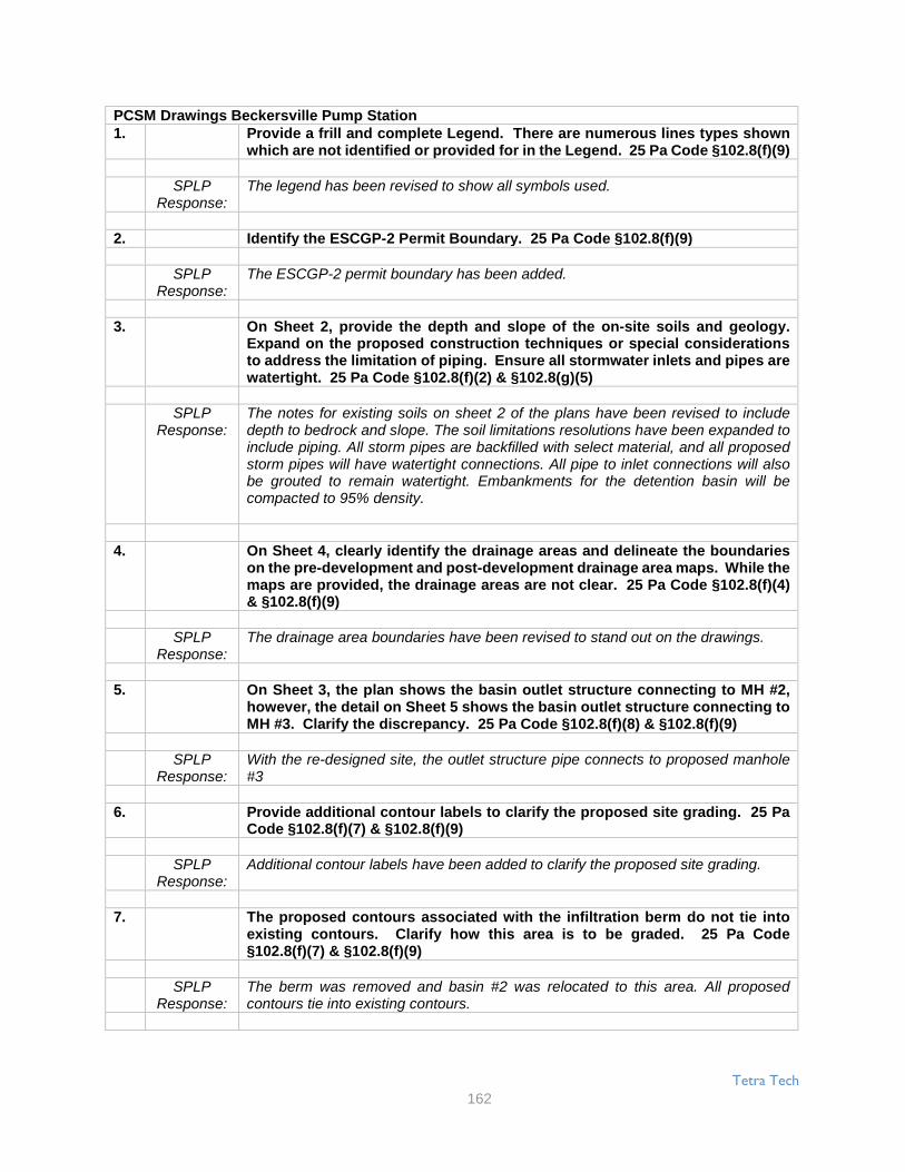
Tetra Tech
162
PCSM Drawings Beckersville Pump Station1. Provide a frill and complete Legend. There are numerous lines types shown
which are not identified or provided for in the Legend. 25 Pa Code §102.8(f)(9)
SPLPResponse:
The legend has been revised to show all symbols used.
2. Identify the ESCGP-2 Permit Boundary. 25 Pa Code §102.8(f)(9)
SPLPResponse:
The ESCGP-2 permit boundary has been added.
3. On Sheet 2, provide the depth and slope of the on-site soils and geology.Expand on the proposed construction techniques or special considerationsto address the limitation of piping. Ensure all stormwater inlets and pipes arewatertight. 25 Pa Code §102.8(f)(2) & §102.8(g)(5)
SPLPResponse:
The notes for existing soils on sheet 2 of the plans have been revised to includedepth to bedrock and slope. The soil limitations resolutions have been expanded toinclude piping. All storm pipes are backfilled with select material, and all proposedstorm pipes will have watertight connections. All pipe to inlet connections will alsobe grouted to remain watertight. Embankments for the detention basin will becompacted to 95% density.
4. On Sheet 4, clearly identify the drainage areas and delineate the boundarieson the pre-development and post-development drainage area maps. While themaps are provided, the drainage areas are not clear. 25 Pa Code §102.8(f)(4)& §102.8(f)(9)
SPLPResponse:
The drainage area boundaries have been revised to stand out on the drawings.
5. On Sheet 3, the plan shows the basin outlet structure connecting to MH #2,however, the detail on Sheet 5 shows the basin outlet structure connecting toMH #3. Clarify the discrepancy. 25 Pa Code §102.8(f)(8) & §102.8(f)(9)
SPLPResponse:
With the re-designed site, the outlet structure pipe connects to proposed manhole#3
6. Provide additional contour labels to clarify the proposed site grading. 25 PaCode §102.8(f)(7) & §102.8(f)(9)
SPLPResponse:
Additional contour labels have been added to clarify the proposed site grading.
7. The proposed contours associated with the infiltration berm do not tie intoexisting contours. Clarify how this area is to be graded. 25 Pa Code§102.8(f)(7) & §102.8(f)(9)
SPLPResponse:
The berm was removed and basin #2 was relocated to this area. All proposedcontours tie into existing contours.

Tetra Tech
163
8. Clarify on the plan if there is any associated work proposed on the plan forthe existing riprap apron, EX RRA, or if it currently meets the design andassociated detail. The plan is not clear, but includes this area within the Limitof Disturbance (LOD). 25 Pa Code §102.8(f)(6) &, §102.8(f)(9)
SPLPResponse:
There is no work planned for the existing riprap apron constructed during ME1.Calculations are provided that prove the RRA is adequate for the total pipe flow fromboth basins. The LOD line has been revised to remove this area from the LODboundary.
9. Provide additional information for the infiltration berms to ensure properconstruction, including providing dimensions and specifying the E&S blanket.25 Pa Code §102.8(f)(6) & §102.8(f)(9)
SPLPResponse:
The infiltration berm was deleted. The slopes will be lined with NA Green S-150erosion control blankets. Additional dimensions for the basin are shown on Sheet#4.
Page 11110. Clarify if the Compost Sock Washout Installation will be a permanent feature
or only used during construction. If it is not permanent, remove it from thePCSM Plan. 25 Pa Code §102.8(f)(6) & §102.8(f)(9)
SPLPResponse:
The washout is not a permanent feature, and therefore was removed from the PCSMPlan.
11. The following comments relate to the long-term operation and maintenance(O&M) schedules for PCSM BMPs: 25 Pa Code §102.8(f)(10) & §102.8(f)(9)
a. Expand on the Detention Basin schedule to include measures to repairand replace to ensure proper function and operation.
SPLPResponse:
The O & M schedule for the detention/infiltration basin was revised to include repairand replacement.
b. Provide a schedule for the infiltration berm.
SPLPResponse:
The schedule was revised to include the infiltration basin.
c. Expand on the rip rap apron schedule to include replacement.
SPLPResponse:
The schedule was revised to include replacement of the riprap aprons.
The following are comments, not technical deficiencies, provided regarding the design of the E&Sand PCSM Plans that DEP and the Districts would like Sunoco Logistics, L.P. and their consultantteam to consider.A. The Lebanon County Conservation District recommends utilizing Jute Matting
for the stabilization of the areas adjacent to flowing surface waters. JuteMatting appears to have better performance and stability for flowing waterversus other 'standard' erosion control blankets.
Tetra Tech
164
SPLPResponse:
Jute Matting is recognized as a good product to stabilize hillsides and stream banks,however, it is also felt that other types of Erosion Control Blankets (ECB) will alsoperform satisfactorily. The contractor may elect to use any of the acceptable ECBswhich meet the requirements in Erosion and Sediment Control Plan narrativedepending on availability.
B. It is recommended to consider placing waterbars at the ends of the rockconstruction entrances, to avoid concentrated runoff leaving the site via therock construction entrance (e.g. Stations 10950+60, 11035+00 & 11048+50)
SPLPResponse:
Diversions will be provided for all Rock Construction Entrances that are slopedtoward roadways. The water will be diverted with a water deflector near the up-gradient end of the rock construction entrance. The general detail for the waterdeflector is already included in the drawing sets (ES-0.10) and the plan location ofthe deflector has been shown on the plan sheets.
C. It appears that erosion control matting/blankets may be used in areas wherelivestock will be present. The use of certain types of erosion controlmatting/blankets may be harmful to livestock. Consideration should be givento using erosion control matting/blankets that are not harmful to livestock, inthe areas where livestock will be present after construction.
SPLPResponse:
In areas where livestock are located an alternative Erosion Control Blanket isproposed. Contractors are to use North American Green BioNet-SC150BN in theseareas. Bio-Net-SC150BN is made of combination of straw and coconut fiber.
D. Crownvetch is an invasive species. Consideration should be given toremoving any invasive species from the E&S and PCSM Plans.
SPLPResponse:
Crown-vetch was replaced in the seed mixtures with Big Bluestem. Big Bluestem isa native alternative recommended in the DCNR's Invasive Plant Fact Sheet(referenced in the E&S report) for Crown-vetch.
Attached are two copies of the revised documents for your review and approval. A CD with the updatedsections is provided with this submission. SPLP appreciates your timely review of this application. Pleasecontact Rob Simcik of Tetra Tech, Inc. with any questions at 412-921-8163, or [email protected].
Sincerely,
Robert F. Simcik, P.E.Project ManagerTetra Tech, Inc.
RFS/clm
Enclosures: Attachments
Tetra Tech
165
cc:File 112IC05958 Ann Roda, DEPBill Himes, DEP Dominic Rocco, DEPChristopher Smith, DEP Chris Myers, BLCCDDoug Stiffler, HCCD Lori Glace, JCCDNeil Imes, PCCD Carl Goshorn, CCCDTiffany Crum, YCCD Rob Christoff, DCCCDKarl Kerchner, LECCD Christopher Thomas, LACCDDan Greig, BECCD Matt Gordon, SunocoMonica Styles, Sunoco Chris Embry, SunocoBrad Schaefer, Tetra Tech Karen Gleason, Tetra Tech