PISO-DNM100-D/T DeviceNet Master PCI Board · PDF filePISO-DNM100 DeviceNet Master API...
138
PISO-DNM100 DeviceNet Master API functions User’s Manual (Ver: 1.0) 2008/02/25 1 PISO-DNM100-D/T DeviceNet Master PCI Board User’s Manual Warranty All products manufactured by ICP DAS are warranted against defective materials for a period of one year from the date of delivery to the original purchaser. Warning ICP DAS assumes no liability for damages consequent to the use of this product. ICP DAS reserves the right to change this manual at any time without notice. The information furnished by ICP DAS is believed to be accurate and reliable. However, no responsibility is assumed by ICP DAS for its use, or for any infringements of patents or other rights of third parties resulting from its use. Copyright Copyright 2007 by ICP DAS Co., LTD. All rights reserved worldwide. Trademark The names used for identification only may be registered trademarks of their respective companies.
Transcript of PISO-DNM100-D/T DeviceNet Master PCI Board · PDF filePISO-DNM100 DeviceNet Master API...
PISO-DNM100 DeviceNet Master API functions User’s Manual (Ver: 1.0) 2008/02/25 1
PISO-DNM100-D/T
DeviceNet Master PCI Board User’s Manual
Warranty
All products manufactured by ICP DAS are warranted against defective materials for a period of one year from the date of delivery to the original purchaser.
Warning
ICP DAS assumes no liability for damages consequent to the use of this product. ICP DAS reserves the right to change this manual at any time without notice. The information furnished by ICP DAS is believed to be accurate and reliable. However, no responsibility is assumed by ICP DAS for its use, or for any infringements of patents or other rights of third parties resulting from its use.
Copyright
Copyright 2007 by ICP DAS Co., LTD. All rights reserved worldwide.
Trademark
The names used for identification only may be registered trademarks of their respective companies.
PISO-DNM100 DeviceNet Master API functions User’s Manual (Ver: 1.0) 2008/02/25 2
Contents
TU1.UT TUGENERAL INFORMATIONUT .................................................................................5
TU1.1 DEVICENET INTRODUCTIONUT .......................................................................................5 TU1.2 DEVICENET APPLICATIONSUT.........................................................................................7 TU1.3 PISO-DNM100 ARCHITECTURE UT.................................................................................8 TU1.4 DEVICENET MASTER CHARACTERISTICSUT......................................................................9 TU1.5 PISO-DNM100 FIRMWARE CHARACTERISTICSUT .........................................................12 TU1.6 FEATURESUT ................................................................................................................14 TU1.7 SPECIFICATIONS UT .......................................................................................................15 TU1.8 BLOCK DIAGRAM UT......................................................................................................16 TU1.9 PRODUCT CHECK LIST UT .............................................................................................17
TU2.UT TUHARDWARE CONFIGURATIONUT .....................................................................18
TU2.1 BOARD LAYOUT UT ........................................................................................................18 TU2.2 JUMPER SELECTIONUT .................................................................................................19 TU2.3 CONNECTOR PIN ASSIGNMENT UT ..................................................................................20
TU2.3.1 5-pin screw terminal connector UT ....................................................................20 TU2.3.2 9-pin D-sub male connector UT .........................................................................21 TU2.3.3 Wire connection UT ..............................................................................................22
TU2.4 INDICATOR LEDUT.......................................................................................................23 TU2.4.1 Green LEDUT ......................................................................................................23 TU2.4.2 Red LEDUT..........................................................................................................23
TU2.5 HARDWARE INSTALLATIONUT ........................................................................................24
TU3.UT TUDRIVER INSTALLATION AND SOFTWARE APPLICATION UT....................25
TU3.1 DRIVER INSTALLATION OF THE PISO-DNM100UT ........................................................26 TU3.2 FLOW DIAGRAM FOR DEBUGGINGUT ............................................................................31 TU3.3 FLOW DIAGRAM FOR I/O CONFIGURATIONUT................................................................32 TU3.4 FLOW DIAGRAM FOR GENERAL I/O OPERATIONUT ........................................................33 TU3.5 FLOW DIAGRAM FOR ON-LINE ADDING/REMOVING DEVICE UT.......................................34 TU3.6 FLOW DIAGRAM FOR “SETATTRIBUTE” AND “GETATTRIBUTE”UT.................................36 TU3.7 FLOW DIAGRAM FOR POLL CONNECTIONUT ..................................................................37 TU3.8 FLOW DIAGRAM FOR BIT-STROBE CONNECTIONUT........................................................38 TU3.9 FLOW DIAGRAM FOR COS CONNECTIONUT...................................................................39 TU3.10 FLOW DIAGRAM FOR CYCLIC CONNECTIONUT.............................................................40
TU4.UT TUFUNCTION DESCRIPTIONUT ...............................................................................41
TU4.1 DLL FUNCTION DEFINITION AND DESCRIPTIONUT ........................................................42
PISO-DNM100 DeviceNet Master API functions User’s Manual (Ver: 1.0) 2008/02/25 3
TU4.2 FUNCTION RETURN CODE UT ........................................................................................48 TU4.3 FLOW DIAGRAM FOR AUTO-CHECK UCMM ARCHITECTURE UT .....................................61 TU4.4 FUNCTION DESCRIPTIONUT ..........................................................................................62
TU4.4.1 DNM100_GetBoardInfUT.................................................................................62 TU4.4.2 DNM100_TotalDNM100BoardUT ...................................................................63 TU4.4.3 DNM100_ActiveBoardUT.................................................................................64 TU4.4.4 DNM100_CloseBoardUT ..................................................................................65 TU4.4.5 DNM100_GetDLLVersion UT...........................................................................66 TU4.4.6 DNM100_GetFirmwareVersionUT ...................................................................67 TU4.4.7 DNM100_ResetFirmwareUT.............................................................................68 TU4.4.8 DNM100_CheckFirmwareModeUT ..................................................................69 TU4.4.9 DNM100_GetMasterMACIDUT.......................................................................70 TU4.4.10 DNM100_SetMasterMACIDUT .....................................................................71 TU4.4.11 DNM100_GetBaudRate UT .............................................................................72 TU4.4.12 DNM100_SetBaudRateUT ..............................................................................73 TU4.4.13 DNM100_GetMasterStatus UT ........................................................................74 TU4.4.14 DNM100_StartDeviceUT ................................................................................75 TU4.4.15 DNM100_StopDevice UT ................................................................................76 TU4.4.16 DNM100_StartAllDevice UT ...........................................................................77 TU4.4.17 DNM100_StopAllDevice UT ...........................................................................78 TU4.4.18 DNM100_AddDevice UT.................................................................................79 TU4.4.19 DNM100_RemoveDeviceUT ..........................................................................80 TU4.4.20 DNM100_GetExplicitStatusUT.......................................................................81 TU4.4.21 DNM100_GetExplicitResult UT ......................................................................82 TU4.4.22 DNM100_GetAttribute UT...............................................................................83 TU4.4.23 DNM100_GetAttributeValue UT .....................................................................84 TU4.4.24 DNM100_SetAttribute UT ...............................................................................85 TU4.4.25 DNM100_SetAttributeResponse UT ................................................................86 TU4.4.26 DNM100_RemoveIOConnectionUT ...............................................................87 TU4.4.27 DNM100_SetBreakOption UT .........................................................................88 TU4.4.28 DNM100_GetBreakOptionUT.........................................................................89 TU4.4.29 DNM100_ClearAllConfigUT ..........................................................................90 TU4.4.30 DNM100_GetLastDeviceErrorUT...................................................................91 TU4.4.31 DNM100_GetDeviceStatus UT ........................................................................92 TU4.4.32 DNM100_DebugDevice UT .............................................................................93 TU4.4.33 DNM100_GetDeviceInfoUT ...........................................................................94 TU4.4.34 DNM100_GetDevicePollInfo UT.....................................................................95 TU4.4.35 DNM100_GetDeviceBitStrobeInfo UT ............................................................96
PISO-DNM100 DeviceNet Master API functions User’s Manual (Ver: 1.0) 2008/02/25 4
TU4.4.36 DNM100_GetDeviceCOSInfo UT ...................................................................97 TU4.4.37 DNM100_GetDeviceCyclicInfo UT.................................................................98 TU4.4.38 DNM100_AutoScanDevice UT ........................................................................99 TU4.4.39 DNM100_GetScanList UT .............................................................................100 TU4.4.40 DNM100_ConfigPollUT ...............................................................................101 TU4.4.41 DNM100_UpdatePollConfigUT ....................................................................102 TU4.4.42 DNM100_ReadPollInputData UT ..................................................................103 TU4.4.43 DNM100_WritePollOutputDataUT...............................................................104 TU4.4.44 DNM100_GetPollStatus UT ...........................................................................105 TU4.4.45 DNM100_GetPollResult UT...........................................................................106 TU4.4.46 DNM100_CheckPollConnectionStatus UT ....................................................107 TU4.4.47 DNM100_ConfigBitStrobeUT.......................................................................108 TU4.4.48 DNM100_UpdateBitStrobeConfigUT ...........................................................109 TU4.4.49 DNM100_ReadBitStrobeInputDataUT .........................................................110 TU4.4.50 DNM100_GetBitStrobeStatusUT ..................................................................111 TU4.4.51 DNM100_GetBitStrobeResultUT..................................................................112 TU4.4.52 DNM100_CheckBitStrobeConnectionStatusUT ...........................................113 TU4.4.53 DNM100_ConfigCOSUT ..............................................................................114 TU4.4.54 DNM100_UpdateCOSConfigUT...................................................................115 TU4.4.55 DNM100_ReadCOSInputDataUT .................................................................116 TU4.4.56 DNM100_WriteCOSOutputDataUT .............................................................117 TU4.4.57 DNM100_GetCOSStatus UT..........................................................................118 TU4.4.58 DNM100_GetCOSResult UT .........................................................................119 TU4.4.59 DNM100_CheckCOSConnectionStatus UT...................................................120 TU4.4.60 DNM100_ConfigCyclicUT ...........................................................................121 TU4.4.61 DNM100_UpdateCyclicConfigUT ................................................................122 TU4.4.62 DNM100_ReadCyclicInputDataUT ..............................................................123 TU4.4.63 DNM100_WriteCyclicOutputDataUT...........................................................124 TU4.4.64 DNM100_GetCyclicStatus UT .......................................................................125 TU4.4.65 DNM100_GetCyclicResult UT.......................................................................126 TU4.4.66 DNM100_CheckCyclicConnectionStatusUT ................................................127
TU5.UT TUDEMO PROGRAMS FOR WINDOWS UT ...............................................................128
TU5.1 A BRIEF INTRODUCTION TO THE DEMO PROGRAMSUT .................................................128 TU5.2 WIRE CONNECTION OF THE CAN BUSUT....................................................................129 TU5.3 VC_DEMO1 INTRODUCTIONUT .................................................................................130 TU5.4 VC_DEMO2 INTRODUCTIONUT .................................................................................133 TU5.5 BCB_DEMO1 INTRODUCTIONUT...............................................................................135 TU5.6 BCB_DEMO2 INTRODUCTIONUT...............................................................................137

PISO-DNM100 DeviceNet Master API functions User’s Manual (Ver: 1.0) 2008/02/25 5
1. General Information
1.1 DeviceNet Introduction
The TCAN T( TCTontroller TATrea TNTetwork) is a serial communication protocol, which efficiently supports distributed real-time control with a very high level of security. It is an especially suited for networking "intelligent" devices as well as sensors and actuators within a system or sub-system. In CAN networks, there is no addressing of subscribers or stations in the conventional sense, but instead, prioritized messages are transmitted. DeviceNet is one kind of the network protocols based on the CAN bus and mainly used for machine control network, such as textile machinery, printing machines, injection molding machinery, or packaging machines, etc. DeviceNet is a low level network that provides connections between simple industrial devices (sensors, actuators) and higher-level devices (controllers), as shown in Figure 1.1.
Figure 1.1 Example of the DeviceNet network
PISO-DNM100 DeviceNet Master API functions User’s Manual (Ver: 1.0) 2008/02/25 6
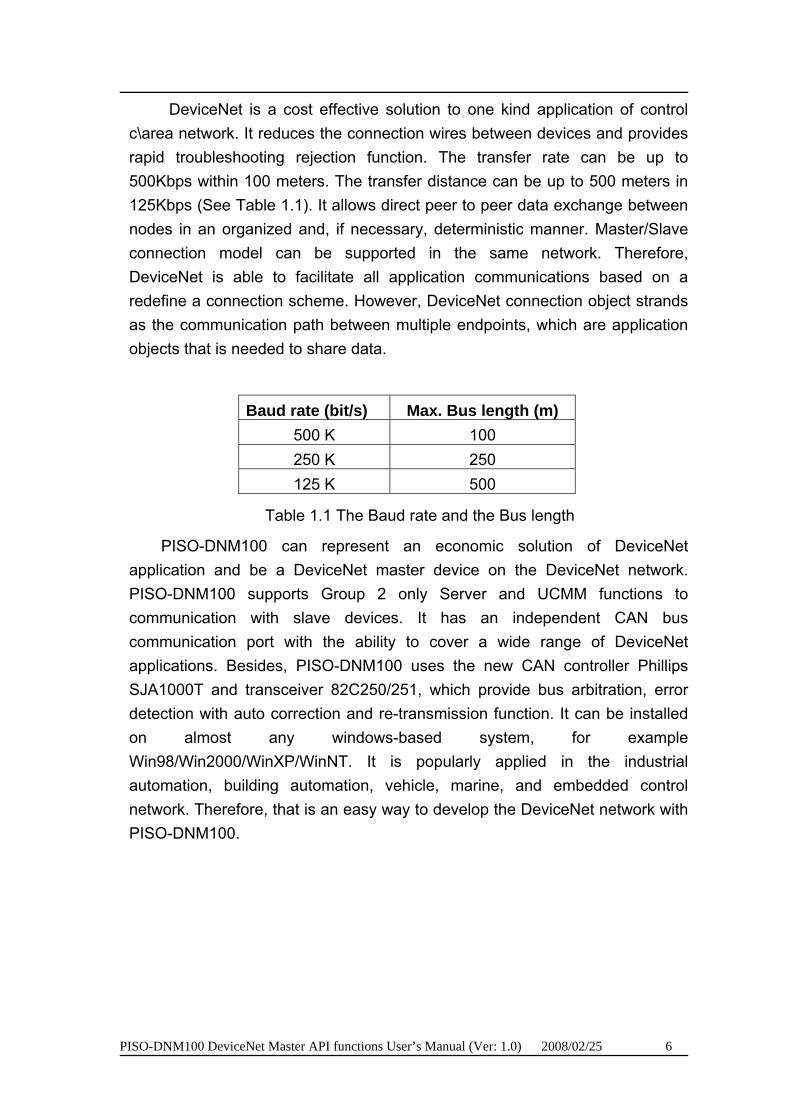
DeviceNet is a cost effective solution to one kind application of control c\area network. It reduces the connection wires between devices and provides rapid troubleshooting rejection function. The transfer rate can be up to 500Kbps within 100 meters. The transfer distance can be up to 500 meters in 125Kbps (See Table 1.1). It allows direct peer to peer data exchange between nodes in an organized and, if necessary, deterministic manner. Master/Slave connection model can be supported in the same network. Therefore, DeviceNet is able to facilitate all application communications based on a redefine a connection scheme. However, DeviceNet connection object strands as the communication path between multiple endpoints, which are application objects that is needed to share data.
Baud rate (bit/s) Max. Bus length (m) 500 K 100 250 K 250 125 K 500
Table 1.1 The Baud rate and the Bus length
PISO-DNM100 can represent an economic solution of DeviceNet application and be a DeviceNet master device on the DeviceNet network. PISO-DNM100 supports Group 2 only Server and UCMM functions to communication with slave devices. It has an independent CAN bus communication port with the ability to cover a wide range of DeviceNet applications. Besides, PISO-DNM100 uses the new CAN controller Phillips SJA1000T and transceiver 82C250/251, which provide bus arbitration, error detection with auto correction and re-transmission function. It can be installed on almost any windows-based system, for example Win98/Win2000/WinXP/WinNT. It is popularly applied in the industrial automation, building automation, vehicle, marine, and embedded control network. Therefore, that is an easy way to develop the DeviceNet network with PISO-DNM100.

PISO-DNM100 DeviceNet Master API functions User’s Manual (Ver: 1.0) 2008/02/25 7
1.2 DeviceNet Applications
DeviceNet is the standardized network application layer optimized for factory automation. It is mainly used in low- and mid-volume automation systems. Some users have also implemented DeviceNet for machine control systems. The main DeviceNet application fields include the following application area (For more information, please refer to HHHTUwww.odva.orgUTHHH):
Production cell builds and tests CPUs Dinnerware production
Beer brewery HVAC module production
Equipment for food packing Textile machines
Fiberglass twist machine Trawler automation system
Sponge production plant LCD manufacturing plant
Isolation wall manufacturing Rolling steel door production
Overhead storage bin production Bottling line
Pocket-bread bakery Tight manufacturing
PISO-DNM100 DeviceNet Master API functions User’s Manual (Ver: 1.0) 2008/02/25 8
1.3 PISO-DNM100 Architecture
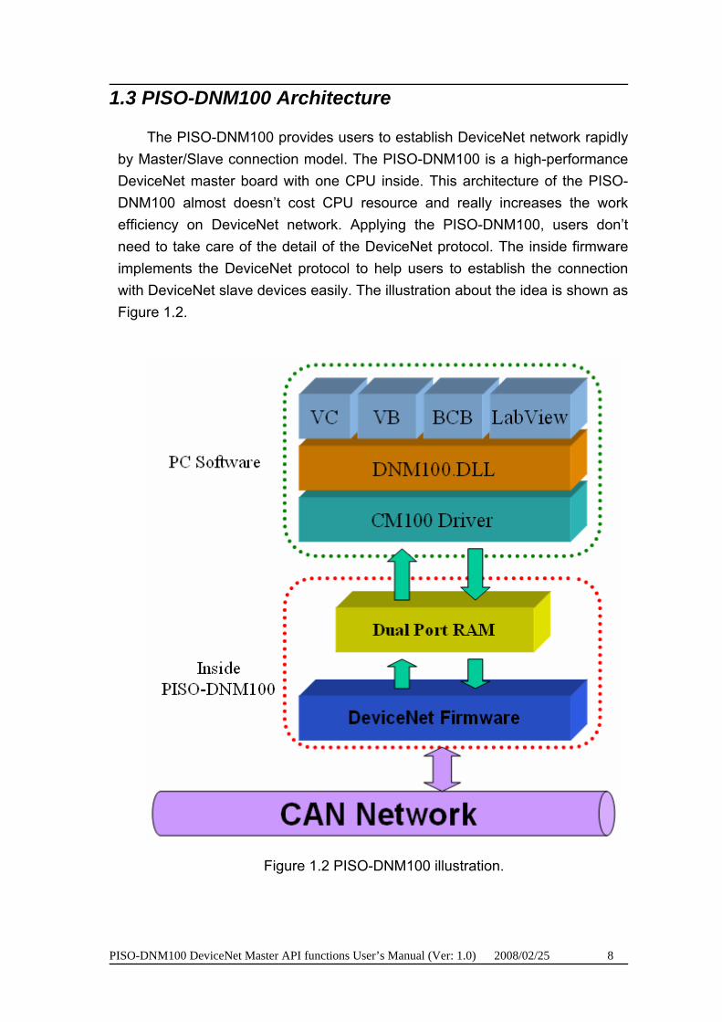
The PISO-DNM100 provides users to establish DeviceNet network rapidly by Master/Slave connection model. The PISO-DNM100 is a high-performance DeviceNet master board with one CPU inside. This architecture of the PISO-DNM100 almost doesn’t cost CPU resource and really increases the work efficiency on DeviceNet network. Applying the PISO-DNM100, users don’t need to take care of the detail of the DeviceNet protocol. The inside firmware implements the DeviceNet protocol to help users to establish the connection with DeviceNet slave devices easily. The illustration about the idea is shown as Figure 1.2.
Figure 1.2 PISO-DNM100 illustration.

PISO-DNM100 DeviceNet Master API functions User’s Manual (Ver: 1.0) 2008/02/25 9
1.4 DeviceNet Master Characteristics
Using the API functions, users don’t need to take care of the detail of the DeviceNet protocol. It can reduce the complexity of user’s DeviceNet Master Software. The firmware mainly supports the Predefined Master-Slave Connection Set and UCMM functions to allow users to merge third party’s DeviceNet devices into the DeviceNet network. It can help users to establish the connection with DeviceNet slave devices easily. The general application architecture is demonstrated as Figure 1.3.
Figure 1.3 Application architecture
PISO-DNM100 DeviceNet Master API functions User’s Manual (Ver: 1.0) 2008/02/25 10
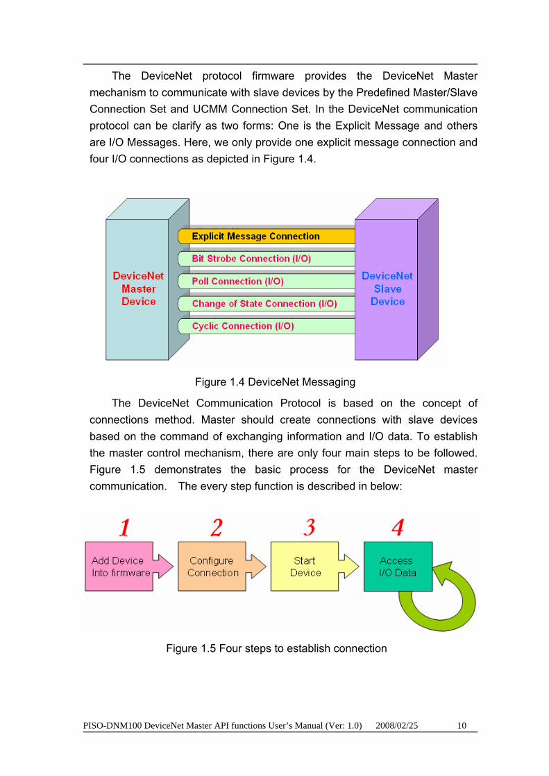
The DeviceNet protocol firmware provides the DeviceNet Master mechanism to communicate with slave devices by the Predefined Master/Slave Connection Set and UCMM Connection Set. In the DeviceNet communication protocol can be clarify as two forms: One is the Explicit Message and others are I/O Messages. Here, we only provide one explicit message connection and four I/O connections as depicted in Figure 1.4.
Figure 1.4 DeviceNet Messaging
The DeviceNet Communication Protocol is based on the concept of connections method. Master should create connections with slave devices based on the command of exchanging information and I/O data. To establish the master control mechanism, there are only four main steps to be followed. Figure 1.5 demonstrates the basic process for the DeviceNet master communication. The every step function is described in below:
Figure 1.5 Four steps to establish connection

PISO-DNM100 DeviceNet Master API functions User’s Manual (Ver: 1.0) 2008/02/25 11
1. Add device into firmware You should provide the slave device’s MAC ID to add into firmware by
using API function. 2. Configure connection
You can check the slave device’s I/O connection type and the I/O data length. When configuring the I/O connection, you should provide these parameters.
3. Start Device After configuring connections, users should start device by using API
function. The master will communicate with the slave device. 4. Access I/O data
After communicating with slave devices, you can access the I/O data with corresponding read/write function.
After adding the device into the firmware, the master will wait for the I/O configuration information. Then users can create the I/O connections in the next step. Once I/O connections have been created and started, I/O data may be exchanged among devices in the DeviceNet network according to master device demand. Therefore, the master device can access I/O data of the slave devices by one of the four I/O connection methods. The API functions are not only easy to use but also providing a lot of the DeviceNet Master functions to retrieve and deliver the slave’s I/O data. For more information, please refer to functions description and demo programs in section 4.

PISO-DNM100 DeviceNet Master API functions User’s Manual (Ver: 1.0) 2008/02/25 12
1.5 PISO-DNM100 Firmware Characteristics
The PISO-DNM100 is a high-performance DeviceNet master board. The firmware inside the board implements DeviceNet protocol automatically when the board is active. The firmware always listens to the bus and receives the message at the same time. It works as shown in Figure 1.6.
Figure 1.6 Message Router
PISO-DNM100 DeviceNet Master API functions User’s Manual (Ver: 1.0) 2008/02/25 13
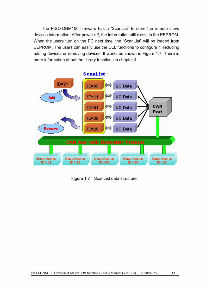
The PISO-DNM100 firmware has a “ScanList” to store the remote slave devices information. After power off, the information still exists in the EEPROM. When the users turn on the PC next time, the “ScanList” will be loaded from EEPROM. The users can easily use the DLL functions to configure it, including adding devices or removing devices. It works as shown in Figure 1.7. There is more information about the library functions in chapter 4.
Figure 1.7 ScanList data structure
PISO-DNM100 DeviceNet Master API functions User’s Manual (Ver: 1.0) 2008/02/25 14
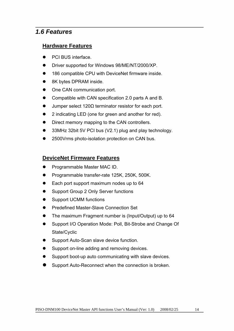
1.6 Features
UHardware Features
PCI BUS interface.
Driver supported for Windows 98/ME/NT/2000/XP.
186 compatible CPU with DeviceNet firmware inside.
8K bytes DPRAM inside.
One CAN communication port.
Compatible with CAN specification 2.0 parts A and B.
Jumper select 120Ω terminator resistor for each port.
2 indicating LED (one for green and another for red).
Direct memory mapping to the CAN controllers.
33MHz 32bit 5V PCI bus (V2.1) plug and play technology.
2500Vrms photo-isolation protection on CAN bus.
UDeviceNet Firmware Features Programmable Master MAC ID.
Programmable transfer-rate 125K, 250K, 500K.
Each port support maximum nodes up to 64
Support Group 2 Only Server functions
Support UCMM functions
Predefined Master-Slave Connection Set
The maximum Fragment number is (Input/Output) up to 64
Support I/O Operation Mode: Poll, Bit-Strobe and Change Of
State/Cyclic
Support Auto-Scan slave device function.
Support on-line adding and removing devices.
Support boot-up auto communicating with slave devices.
Support Auto-Reconnect when the connection is broken.
PISO-DNM100 DeviceNet Master API functions User’s Manual (Ver: 1.0) 2008/02/25 15
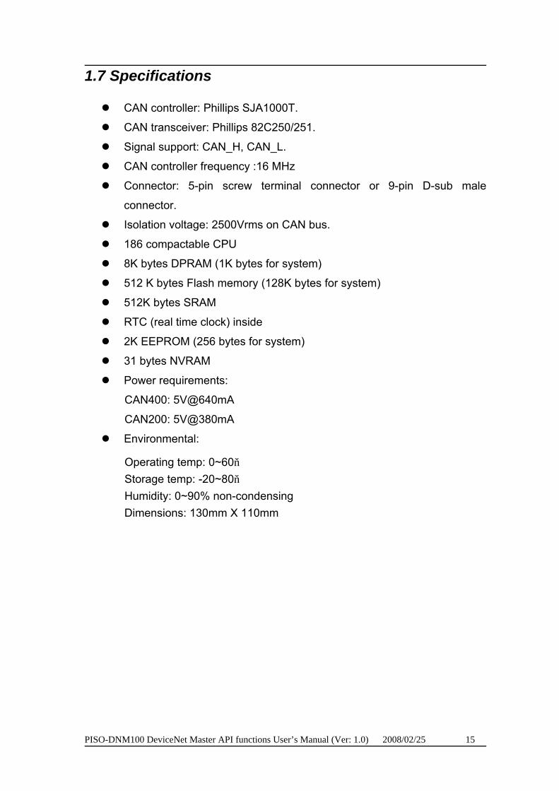
1.7 Specifications
CAN controller: Phillips SJA1000T.
CAN transceiver: Phillips 82C250/251.
Signal support: CAN_H, CAN_L.
CAN controller frequency :16 MHz
Connector: 5-pin screw terminal connector or 9-pin D-sub male
connector.
Isolation voltage: 2500Vrms on CAN bus.
186 compactable CPU
8K bytes DPRAM (1K bytes for system)
512 K bytes Flash memory (128K bytes for system)
512K bytes SRAM
RTC (real time clock) inside
2K EEPROM (256 bytes for system)
31 bytes NVRAM
Power requirements:
CAN400: 5V@640mA
CAN200: 5V@380mA
Environmental:
Operating temp: 0~60 Storage temp: -20~80 Humidity: 0~90% non-condensing Dimensions: 130mm X 110mm
PISO-DNM100 DeviceNet Master API functions User’s Manual (Ver: 1.0) 2008/02/25 16
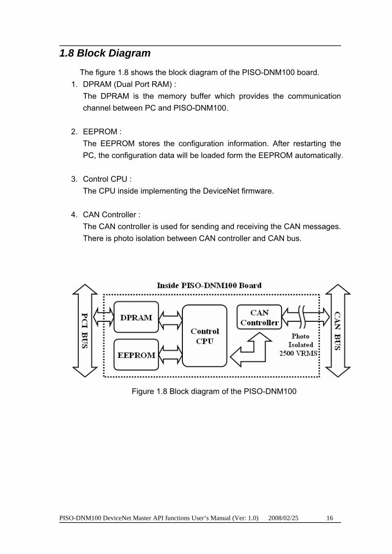
1.8 Block Diagram
The figure 1.8 shows the block diagram of the PISO-DNM100 board. 1. DPRAM (Dual Port RAM) :
The DPRAM is the memory buffer which provides the communication channel between PC and PISO-DNM100.
2. EEPROM : The EEPROM stores the configuration information. After restarting the PC, the configuration data will be loaded form the EEPROM automatically.
3. Control CPU : The CPU inside implementing the DeviceNet firmware.
4. CAN Controller :
The CAN controller is used for sending and receiving the CAN messages. There is photo isolation between CAN controller and CAN bus.
Figure 1.8 Block diagram of the PISO-DNM100
PISO-DNM100 DeviceNet Master API functions User’s Manual (Ver: 1.0) 2008/02/25 17
1.9 Product Check List
In addition to this manual, the package includes the following items: PISO-DNM100 card; Software CD ROM; User manual; Quick Start manual; Release Note It is recommended that users should read the release note first. All of
the important information needed will be provided in the release note as follows:
Where you can find the software driver, utility and demo programs. How to install software & utility. Where is the diagnostic program? FAQ’s and answers.
Attention !
If any of these items are missing or damaged, please contact your local field agent. Keep aside the shipping materials and carton in case you want to ship or store the product in the future.
PISO-DNM100 DeviceNet Master API functions User’s Manual (Ver: 1.0) 2008/02/25 18
2. Hardware Configuration
This section will describe the hardware settings of the PISO-DNM100. This information includes the wire connection and terminal resistance configuration for the CAN network.
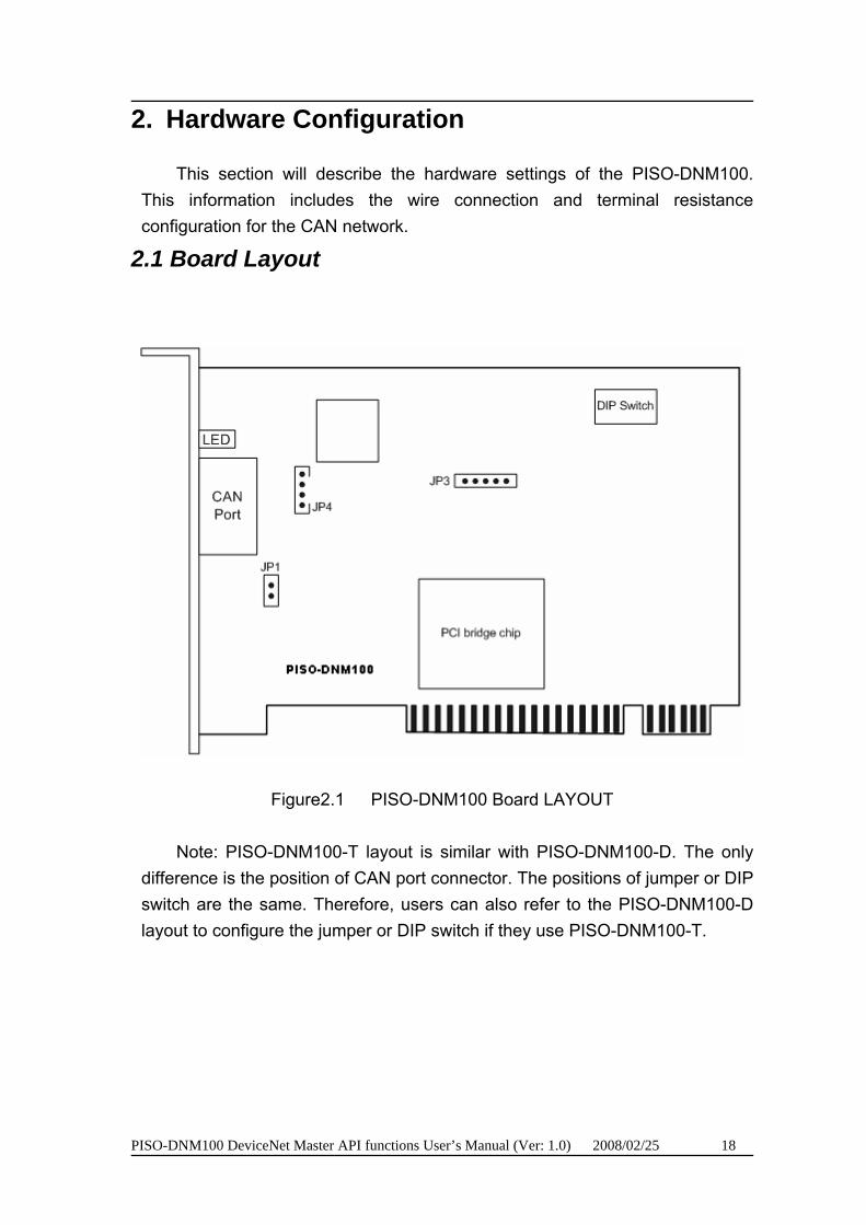
2.1 Board Layout
Figure2.1 PISO-DNM100 Board LAYOUT
Note: PISO-DNM100-T layout is similar with PISO-DNM100-D. The only difference is the position of CAN port connector. The positions of jumper or DIP switch are the same. Therefore, users can also refer to the PISO-DNM100-D layout to configure the jumper or DIP switch if they use PISO-DNM100-T.
PISO-DNM100 DeviceNet Master API functions User’s Manual (Ver: 1.0) 2008/02/25 19
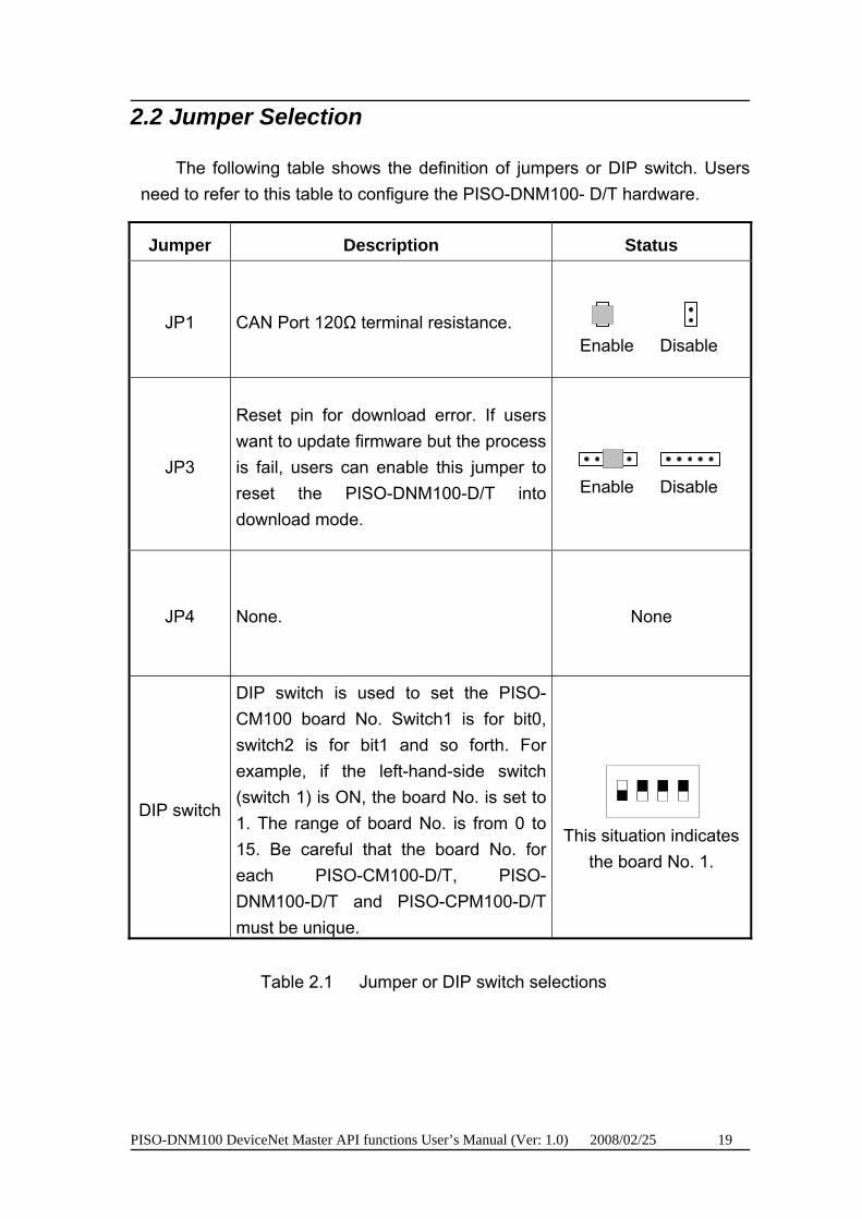
2.2 Jumper Selection
The following table shows the definition of jumpers or DIP switch. Users need to refer to this table to configure the PISO-DNM100- D/T hardware.
Jumper Description Status
JP1 CAN Port 120Ω terminal resistance. Enable Disable
JP3
Reset pin for download error. If users want to update firmware but the process is fail, users can enable this jumper to reset the PISO-DNM100-D/T into download mode.
Enable Disable
JP4 None. None
DIP switch
DIP switch is used to set the PISO-CM100 board No. Switch1 is for bit0, switch2 is for bit1 and so forth. For example, if the left-hand-side switch (switch 1) is ON, the board No. is set to 1. The range of board No. is from 0 to 15. Be careful that the board No. for each PISO-CM100-D/T, PISO-DNM100-D/T and PISO-CPM100-D/T must be unique.
This situation indicates
the board No. 1.
Table 2.1 Jumper or DIP switch selections

PISO-DNM100 DeviceNet Master API functions User’s Manual (Ver: 1.0) 2008/02/25 20
2.3 Connector Pin Assignment
The PISO-DNM100-T is equipped with one 5-pin screw terminal connector and the PISO-DNM100-D is equipped with one 9-pin D-sub male connector for wire connection of the CAN bus. The connector’s pin assignment is specified as follows:
2.3.1 5-pin screw terminal connector
The 5-pin screw terminal connector for the CAN bus is shown in Figure 2.4 and the details for the pin assignment are presented in Table 2.2.
1 2 3 4 5
CAN-L CAN-HShield
Figure2.4 5-pin screw terminal connector
Pin No. Signal Description 1 N/A No use 2 CAN_H CAN_H bus line (dominant high) 3 CAN_SHLD Optional CAN Shield 4 CAN_L CAN_L bus line (dominant low) 5 N/A No use
Table 2.2: Pin assignment of 5-pin screw terminal connector
PISO-DNM100 DeviceNet Master API functions User’s Manual (Ver: 1.0) 2008/02/25 21
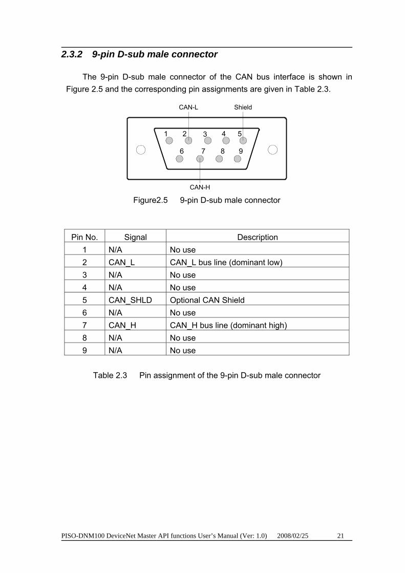
2.3.2 9-pin D-sub male connector
The 9-pin D-sub male connector of the CAN bus interface is shown in Figure 2.5 and the corresponding pin assignments are given in Table 2.3.
2
7
1 3
8 9
54
6
CAN-L
CAN-H
Shield
Figure2.5 9-pin D-sub male connector
Pin No. Signal Description 1 N/A No use 2 CAN_L CAN_L bus line (dominant low) 3 N/A No use 4 N/A No use 5 CAN_SHLD Optional CAN Shield 6 N/A No use 7 CAN_H CAN_H bus line (dominant high) 8 N/A No use 9 N/A No use
Table 2.3 Pin assignment of the 9-pin D-sub male connector

PISO-DNM100 DeviceNet Master API functions User’s Manual (Ver: 1.0) 2008/02/25 22
2.3.3 Wire connection
In order to minimize the reflection effects on the CAN bus line, the CAN bus line has to be terminated at both ends by two terminal resistances as in the following figure. According to the ISO 11898-2 spec, each terminal resistance is 120Ω (or between 108Ω~132Ω). The length related resistance should have 70 mΩ/m. Users should check the resistances of the CAN bus, before they install a new CAN network.
120Ω
120Ω
CAN_H
CAN_L
Device NDevice 2Device 1 . . .
Figure 2.4 CAN bus network topology
Moreover, to minimize the voltage drop over long distances, the terminal
resistance should be higher than the value defined in the ISO 11898-2. The following table can be used as a good reference.
Bus Cable Parameters Bus Length
(meter) Length Related
Resistance (mΩ/m)
Cross Section (Type)
Terminal Resistance
(Ω)
0~40 70 0.25(23AWG)~ 0.34mm P
2P(22AWG)
124 (0.1%)
40~300 < 60 0.34(22AWG)~ 0.6mm P
2P(20AWG)
127 (0.1%)
300~600 < 40 0.5~0.6mm P
2
(20AWG) 150~300
600~1K < 20 0.75~0.8mm P
2P
(18AWG) 150~300
Table 2.4 Relationship between cable characteristics and terminal resistance
PISO-DNM100 DeviceNet Master API functions User’s Manual (Ver: 1.0) 2008/02/25 23
2.4 Indicator LED
2.4.1 UGreenU LED
The [Green] LED indicates the firmware status in the PISO-DNM100. There are 3 situations in [Green] LED.
(1). LED off:
This indicates that there are some errors on the bus or in the firmware. The DeviceNet firmware is not running.
(2). LED twinkle:
This indicates that the CAN bus works fine. But there is no any slave devices configuration in the EEPROM of the PISO-DNM100. The DeviceNet firmware is waiting for configuration.
(3). LED on:
This indicates that the DeviceNet firmware is running. The PISO-DNM100 is communicating with the slave devices.
2.4.2 URedU LED
The [Red] LED means Network Status. It indicates that there are errors on the bus or there is any slave device's MAC ID collides with the PISO-DNM100's MAC ID. There are two situations in [Red] LED.
(1). LED off:
This indicates that there is no error on the bus and about the MAC ID.
(2). LED twinkle:
This indicates that there are errors on the bus which maybe the situations as shown bellow:
(a) The CAN connector doesn't connect to the slave devices. (b) The power of the slave devices is off. (c) The MAC ID collision between master and slave devices is occurring.

PISO-DNM100 DeviceNet Master API functions User’s Manual (Ver: 1.0) 2008/02/25 24
2.5 Hardware Installation
When users want to use PISO-DNM100-D/T, the hardware installation needs to be finished as following steps.
1. Shutdown your personal computer.
2. Configure the DIP switch and JP1 of your PISO-DNM100-D/T for board No. and terminal resistance. More detail information could be found on the figure 2.1 and table 2.1.
3. Check JP3 status of PISO-DNM100-D/T. If necessary, enable it.
4. Find an empty PCI slot for your PISO-DNM100-D/T on the mother board of the personal computer. Plug the configured PISO-DNM100-D/T into this empty PCI slot. See figure 2.5.
5. Plug your CAN bus cable(s) into the 5-pin screw terminal connector or the 9-pin D-sub connector.
When the steps described above is completed, turn on the personal computer.
Figure 2.5 PISO-DNM100 installation

PISO-DNM100 DeviceNet Master API functions User’s Manual (Ver: 1.0) 2008/02/25 25
3. Driver Installation and Software Application
The DeviceNet DLL driver (DNM100.dll) collection of function calls for the PISO-DNM100 cards used in Windows 98/Me/NT/2000/XP systems. The application structure is presented in the following figure. The user’s DeviceNet application programs can be developed by the following designated tools: VB, Delphi and Borland C++ Builder…etc. In these tools, the application program can call the DNM100.DLL driver to implement DeviceNet network application. And then the DeviceNet DLL driver will throughout the CM100.dll into the KP_CM100.sys and windrvr6.sys to access the hardware system, as shown in the following Figure.
Figure 3.1 Software architecture in the Windows system
In the following sub-section, we show some flow diagrams to describe how to apply the DeviceNet protocol (DNM100.DLL) to build a master device. Section 3.2 ~ 3.10 show the flow diagram for users to understand easily. Note that users need to follow the operation principle of the DeviceNet protocol correctly and easily to communicate with the remote nodes by these connection methods.
PISO-DNM100 DeviceNet Master API functions User’s Manual (Ver: 1.0) 2008/02/25 26
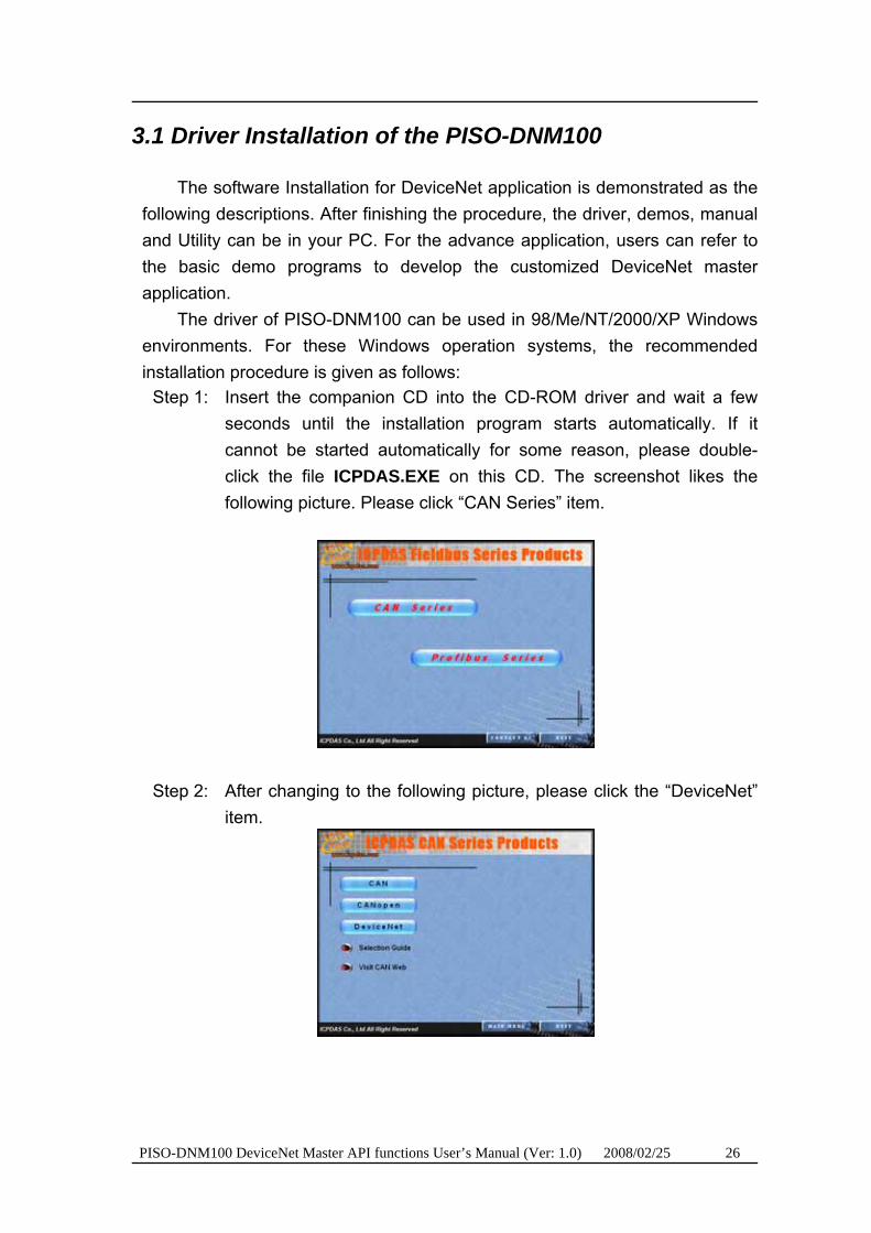
3.1 Driver Installation of the PISO-DNM100
The software Installation for DeviceNet application is demonstrated as the following descriptions. After finishing the procedure, the driver, demos, manual and Utility can be in your PC. For the advance application, users can refer to the basic demo programs to develop the customized DeviceNet master application.
The driver of PISO-DNM100 can be used in 98/Me/NT/2000/XP Windows environments. For these Windows operation systems, the recommended installation procedure is given as follows:
Step 1: Insert the companion CD into the CD-ROM driver and wait a few seconds until the installation program starts automatically. If it cannot be started automatically for some reason, please double-click the file ICPDAS.EXE on this CD. The screenshot likes the following picture. Please click “CAN Series” item.
Step 2: After changing to the following picture, please click the “DeviceNet” item.
PISO-DNM100 DeviceNet Master API functions User’s Manual (Ver: 1.0) 2008/02/25 27
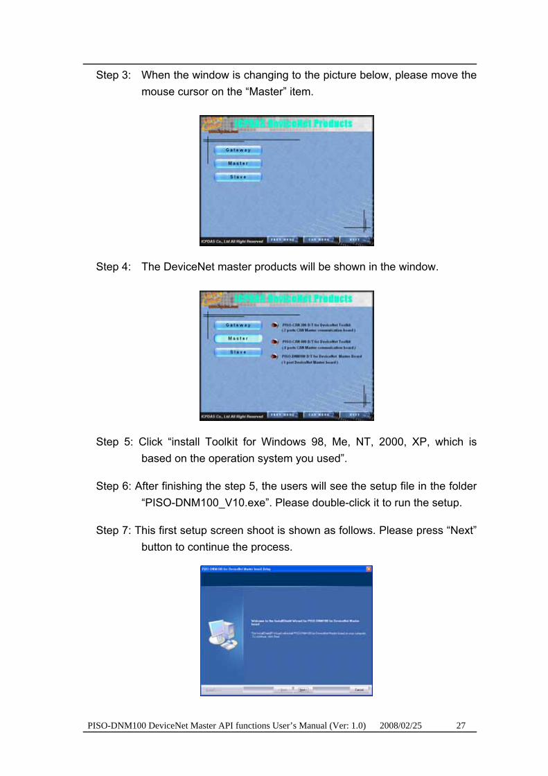
Step 3: When the window is changing to the picture below, please move the mouse cursor on the “Master” item.
Step 4: The DeviceNet master products will be shown in the window.
Step 5: Click “install Toolkit for Windows 98, Me, NT, 2000, XP, which is based on the operation system you used”.
Step 6: After finishing the step 5, the users will see the setup file in the folder “PISO-DNM100_V10.exe”. Please double-click it to run the setup.
Step 7: This first setup screen shoot is shown as follows. Please press “Next” button to continue the process.

PISO-DNM100 DeviceNet Master API functions User’s Manual (Ver: 1.0) 2008/02/25 28
Step 8: Press “Next” button. The screen shoot is shown below. After reading the license, the users can accept it or not. If the users accept it, please select “I accept….” and press “Next” button.
Step 9: After accepting the license, the next screen shoot is shown as follows. Users can edit your name and company name. After editing the information, please press “Next” button.
Step 10: After editing the information, the next screen shoot is shown as follows. Please select “Complete” item and press “Next” button.

PISO-DNM100 DeviceNet Master API functions User’s Manual (Ver: 1.0) 2008/02/25 29
Step 11: The next screen shoot is shown as follows. Please press “Install” button. The setup process will start.
Step 12: The setup process is running. The screen shoot is shown below.
Step 13: Wait for the setup process finishing. The next screen shoot is shown below. After finishing the process, please press “Finish” button.
PISO-DNM100 DeviceNet Master API functions User’s Manual (Ver: 1.0) 2008/02/25 30
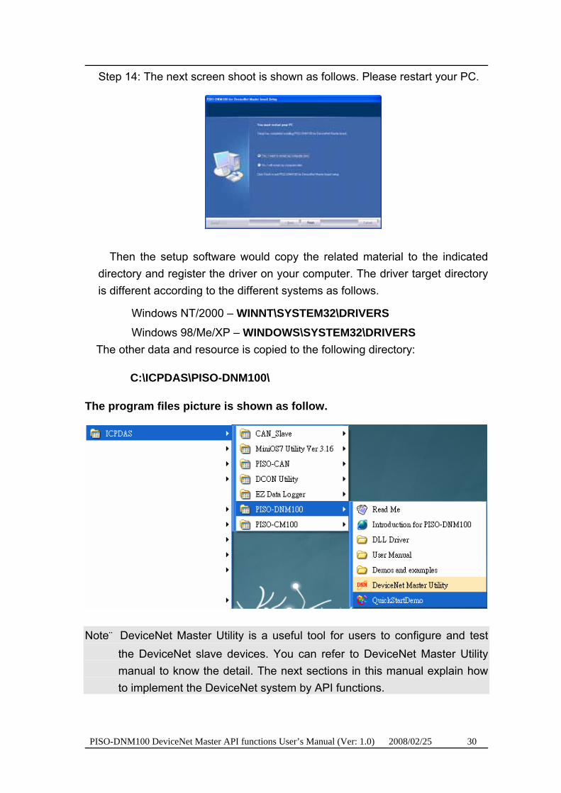
Step 14: The next screen shoot is shown as follows. Please restart your PC.
Then the setup software would copy the related material to the indicated directory and register the driver on your computer. The driver target directory is different according to the different systems as follows.
Windows NT/2000 – WINNT\SYSTEM32\DRIVERS Windows 98/Me/XP – WINDOWS\SYSTEM32\DRIVERS
The other data and resource is copied to the following directory:
C:\ICPDAS\PISO-DNM100\
The program files picture is shown as follow.
Note:DeviceNet Master Utility is a useful tool for users to configure and test the DeviceNet slave devices. You can refer to DeviceNet Master Utility manual to know the detail. The next sections in this manual explain how to implement the DeviceNet system by API functions.

PISO-DNM100 DeviceNet Master API functions User’s Manual (Ver: 1.0) 2008/02/25 31
3.2 Flow Diagram for Debugging
Before developing the DeviceNet applications, users should test to connect to the slave devices. When users have no idea to communicate with them, users can follow these steps shown in figure 3.2. The following functions can help users to get the DeviceNet information of the slave devices. The users can choose one of them to find out the problem of the slave devices. The detail information about those functions is in the next chapter.
Figure 3.2 Debugging Diagram
PISO-DNM100 DeviceNet Master API functions User’s Manual (Ver: 1.0) 2008/02/25 32
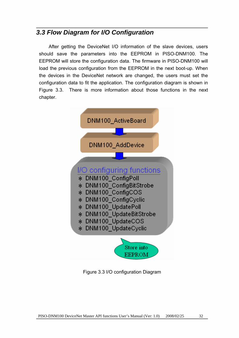
3.3 Flow Diagram for I/O Configuration
After getting the DeviceNet I/O information of the slave devices, users should save the parameters into the EEPROM in PISO-DNM100. The EEPROM will store the configuration data. The firmware in PISO-DNM100 will load the previous configuration from the EEPROM in the next boot-up. When the devices in the DeviceNet network are changed, the users must set the configuration data to fit the application. The configuration diagram is shown in Figure 3.3. There is more information about those functions in the next chapter.
Figure 3.3 I/O configuration Diagram

PISO-DNM100 DeviceNet Master API functions User’s Manual (Ver: 1.0) 2008/02/25 33
3.4 Flow Diagram for General I/O Operation
After configuring the PISO-DNM100, the users can easily read or write I/O data from or to the remote DeviceNet slave devices. The users don't need to know about the DeviceNet protocol. The main steps are shown in Figure 3.5. There are more detail descriptions in chapter 3.6 ~ 3.10.
Figure 3.5 General I/O Diagram
PISO-DNM100 DeviceNet Master API functions User’s Manual (Ver: 1.0) 2008/02/25 34
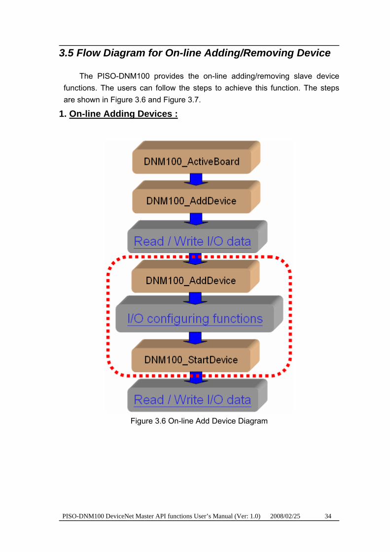
3.5 Flow Diagram for On-line Adding/Removing Device
The PISO-DNM100 provides the on-line adding/removing slave device functions. The users can follow the steps to achieve this function. The steps are shown in Figure 3.6 and Figure 3.7.
1. UOn-line Adding Devices :
Figure 3.6 On-line Add Device Diagram

PISO-DNM100 DeviceNet Master API functions User’s Manual (Ver: 1.0) 2008/02/25 35
2. UOn-line Removing Devices :
Figure 3.7 On-line Remove Device Diagram
PISO-DNM100 DeviceNet Master API functions User’s Manual (Ver: 1.0) 2008/02/25 36
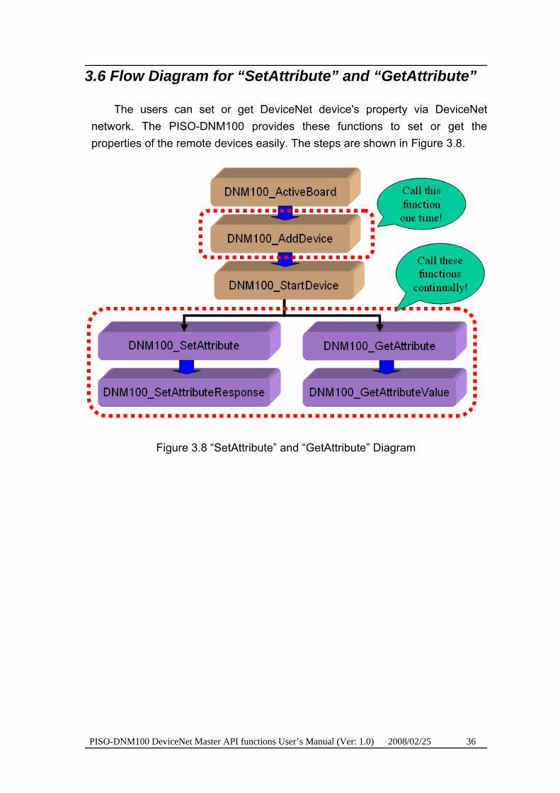
3.6 Flow Diagram for “SetAttribute” and “GetAttribute”
The users can set or get DeviceNet device's property via DeviceNet network. The PISO-DNM100 provides these functions to set or get the properties of the remote devices easily. The steps are shown in Figure 3.8.
Figure 3.8 “SetAttribute” and “GetAttribute” Diagram
PISO-DNM100 DeviceNet Master API functions User’s Manual (Ver: 1.0) 2008/02/25 37
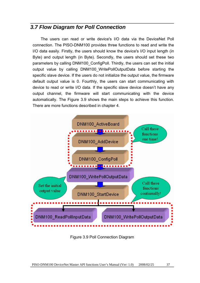
3.7 Flow Diagram for Poll Connection
The users can read or write device's I/O data via the DeviceNet Poll connection. The PISO-DNM100 provides three functions to read and write the I/O data easily. Firstly, the users should know the device's I/O input length (in Byte) and output length (in Byte). Secondly, the users should set these two parameters by calling DNM100_ConfigPoll. Thirdly, the users can set the initial output value by calling DNM100_WritePollOutputData before starting the specific slave device. If the users do not initialize the output value, the firmware default output value is 0. Fourthly, the users can start communicating with device to read or write I/O data. If the specific slave device doesn’t have any output channel, the firmware will start communicating with the device automatically. The Figure 3.9 shows the main steps to achieve this function. There are more functions described in chapter 4.
Figure 3.9 Poll Connection Diagram

PISO-DNM100 DeviceNet Master API functions User’s Manual (Ver: 1.0) 2008/02/25 38
3.8 Flow Diagram for Bit-Strobe Connection
The users can read device's I/O data via DeviceNet Bit-Strobe connection. The PISO-DNM100 provides two functions to read the I/O data easily. Firstly, the users should know the device's I/O input length (in Byte). Secondly, the users should set this parameter by calling DNM100_ConfigBitStrobe. Thirdly, the users can start communicating with device to read I/O data. The Figure 3.10 shows the main steps to achieve this function. There are more functions described in chapter 4.
Figure 3.10 Bit-Strobe Connection Diagram
PISO-DNM100 DeviceNet Master API functions User’s Manual (Ver: 1.0) 2008/02/25 39
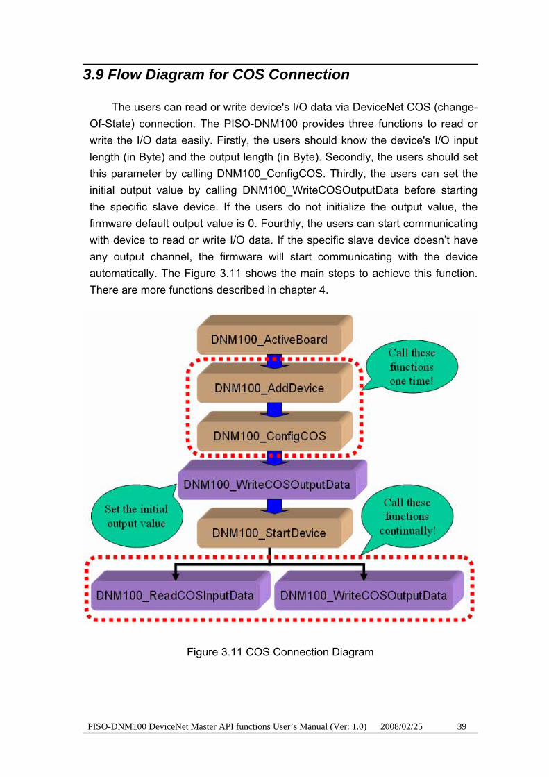
3.9 Flow Diagram for COS Connection
The users can read or write device's I/O data via DeviceNet COS (change-Of-State) connection. The PISO-DNM100 provides three functions to read or write the I/O data easily. Firstly, the users should know the device's I/O input length (in Byte) and the output length (in Byte). Secondly, the users should set this parameter by calling DNM100_ConfigCOS. Thirdly, the users can set the initial output value by calling DNM100_WriteCOSOutputData before starting the specific slave device. If the users do not initialize the output value, the firmware default output value is 0. Fourthly, the users can start communicating with device to read or write I/O data. If the specific slave device doesn’t have any output channel, the firmware will start communicating with the device automatically. The Figure 3.11 shows the main steps to achieve this function. There are more functions described in chapter 4.
Figure 3.11 COS Connection Diagram

PISO-DNM100 DeviceNet Master API functions User’s Manual (Ver: 1.0) 2008/02/25 40
3.10 Flow Diagram for Cyclic Connection
The users can read or write device's I/O data via DeviceNet Cyclic connection. The PISO-DNM100 provides three functions to read or write the I/O data easily. Firstly, the users should know the device's I/O input length (in Byte) and the output length (in Byte). Secondly, the users should set this parameter by calling DNM100_ConfigCyclic. Thirdly, the users can set the initial output value by calling DNM100_WriteCyclicOutputData before starting the specific slave device. If the users do not initialize the output value, the firmware default output value is 0. Fourthly, the users can start communicating with device to read or write I/O data. If the specific slave device doesn’t have any output channel, the firmware will start communicating with the device automatically. The Figure 3.12 shows the main steps to achieve this function. There are more functions described in chapter 4.
Figure 3.12 Cyclic Connection Diagram

PISO-DNM100 DeviceNet Master API functions User’s Manual (Ver: 1.0) 2008/02/25 41
4. Function description
All the functions of the PISO-DNM100 can be separated into five groups. The idea is shown Figure 4.1. There is more detail description in CH 4.1.
Figure 4.1 Five Function Groups
U[Board Functions] These functions in this group help users to find DNM100 boards or get
board’s information. The users can use these functions to configure or manage the boards in the PC.
U[Firmware Functions]
These functions in this group help users to operate the firmware or get the status of the firmware inside the PISO-DNM100.
U[Operating Functions]
These operating functions are the important operation of the DeviceNet master. They help users to configure the whole network.
U[Debugging Function]
These debugging functions can help user to debug the network, including the wire connection, the slave device’s setting…etc. When building the DeviceNet network, the user can use these functions to make sure that the network or the slave devices are fine.
U[I/O Functions]
These functions help user to read or to write the I/O data from or to the remote slave devices.
PISO-DNM100 DeviceNet Master API functions User’s Manual (Ver: 1.0) 2008/02/25 42
4.1 DLL Function Definition and Description
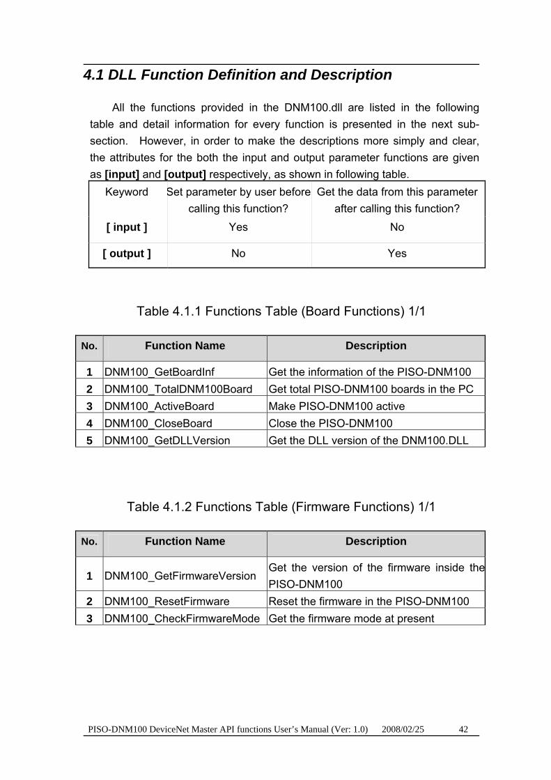
All the functions provided in the DNM100.dll are listed in the following table and detail information for every function is presented in the next sub-section. However, in order to make the descriptions more simply and clear, the attributes for the both the input and output parameter functions are given as [input] and [output] respectively, as shown in following table.
Keyword Set parameter by user before calling this function?
Get the data from this parameter after calling this function?
[ input ] Yes No
[ output ] No Yes
Table 4.1.1 Functions Table (Board Functions) 1/1
TNo. T TFunction NameT TDescriptionT
1 DNM100_GetBoardInf Get the information of the PISO-DNM100 2 DNM100_TotalDNM100Board Get total PISO-DNM100 boards in the PC 3 DNM100_ActiveBoard Make PISO-DNM100 active 4 DNM100_CloseBoard Close the PISO-DNM100 5 DNM100_GetDLLVersion Get the DLL version of the DNM100.DLL
Table 4.1.2 Functions Table (Firmware Functions) 1/1
TNo. T TFunction NameT TDescriptionT
1 DNM100_GetFirmwareVersion Get the version of the firmware inside thePISO-DNM100
2 DNM100_ResetFirmware Reset the firmware in the PISO-DNM100 3 DNM100_CheckFirmwareMode Get the firmware mode at present
PISO-DNM100 DeviceNet Master API functions User’s Manual (Ver: 1.0) 2008/02/25 43
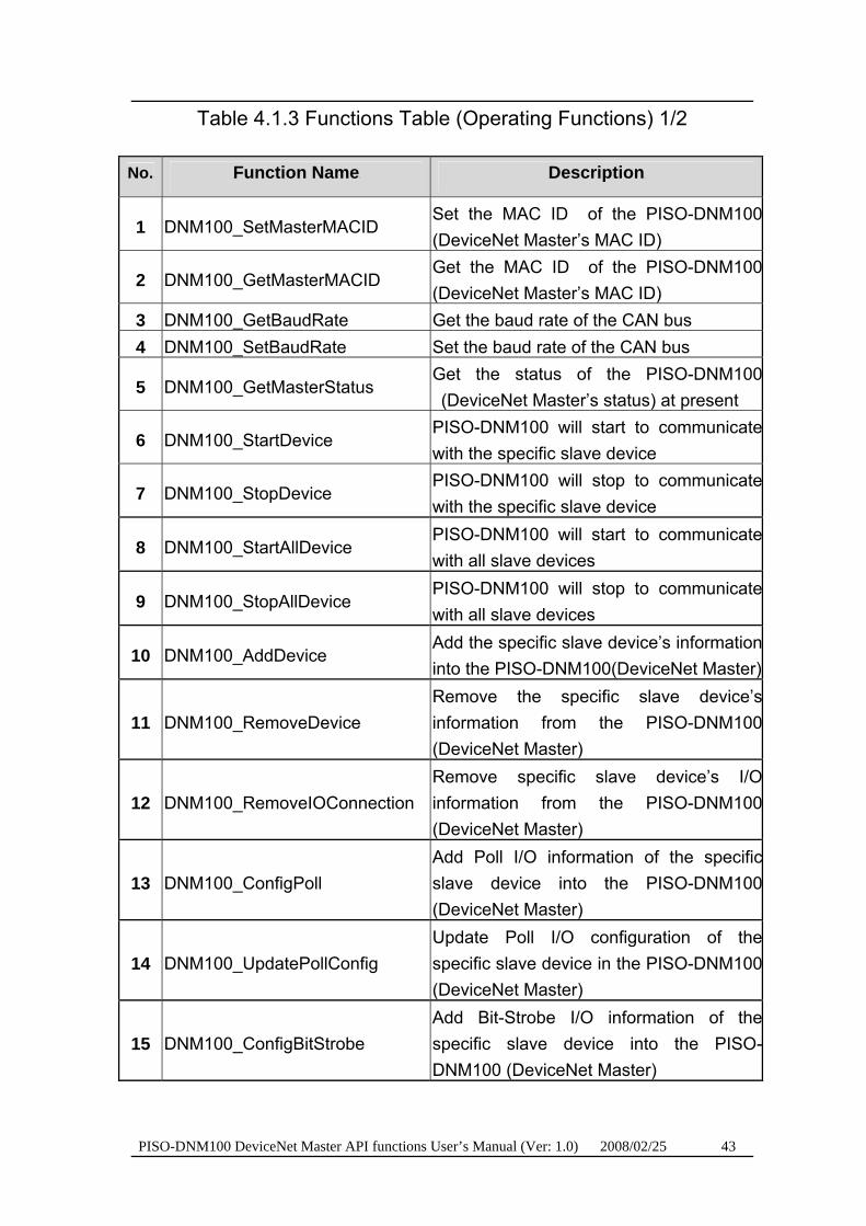
Table 4.1.3 Functions Table (Operating Functions) 1/2
TNo. T TFunction NameT TDescriptionT
1 DNM100_SetMasterMACID Set the MAC ID of the PISO-DNM100(DeviceNet Master’s MAC ID)
2 DNM100_GetMasterMACID Get the MAC ID of the PISO-DNM100(DeviceNet Master’s MAC ID)
3 DNM100_GetBaudRate Get the baud rate of the CAN bus 4 DNM100_SetBaudRate Set the baud rate of the CAN bus
5 DNM100_GetMasterStatus Get the status of the PISO-DNM100(DeviceNet Master’s status) at present
6 DNM100_StartDevice PISO-DNM100 will start to communicatewith the specific slave device
7 DNM100_StopDevice PISO-DNM100 will stop to communicatewith the specific slave device
8 DNM100_StartAllDevice PISO-DNM100 will start to communicatewith all slave devices
9 DNM100_StopAllDevice PISO-DNM100 will stop to communicatewith all slave devices
10 DNM100_AddDevice Add the specific slave device’s informationinto the PISO-DNM100(DeviceNet Master)
11 DNM100_RemoveDevice Remove the specific slave device’sinformation from the PISO-DNM100(DeviceNet Master)
12 DNM100_RemoveIOConnection Remove specific slave device’s I/Oinformation from the PISO-DNM100(DeviceNet Master)
13 DNM100_ConfigPoll Add Poll I/O information of the specificslave device into the PISO-DNM100(DeviceNet Master)
14 DNM100_UpdatePollConfig Update Poll I/O configuration of thespecific slave device in the PISO-DNM100(DeviceNet Master)
15 DNM100_ConfigBitStrobe Add Bit-Strobe I/O information of thespecific slave device into the PISO-DNM100 (DeviceNet Master)
PISO-DNM100 DeviceNet Master API functions User’s Manual (Ver: 1.0) 2008/02/25 44
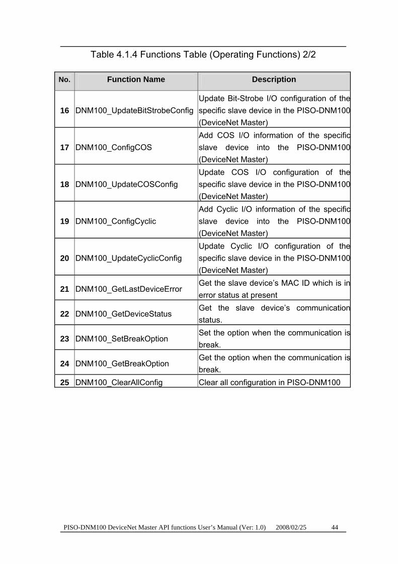
Table 4.1.4 Functions Table (Operating Functions) 2/2
TNo. T TFunction NameT TDescriptionT
16 DNM100_UpdateBitStrobeConfigUpdate Bit-Strobe I/O configuration of thespecific slave device in the PISO-DNM100(DeviceNet Master)
17 DNM100_ConfigCOS Add COS I/O information of the specificslave device into the PISO-DNM100(DeviceNet Master)
18 DNM100_UpdateCOSConfig Update COS I/O configuration of thespecific slave device in the PISO-DNM100(DeviceNet Master)
19 DNM100_ConfigCyclic Add Cyclic I/O information of the specificslave device into the PISO-DNM100(DeviceNet Master)
20 DNM100_UpdateCyclicConfig Update Cyclic I/O configuration of thespecific slave device in the PISO-DNM100(DeviceNet Master)
21 DNM100_GetLastDeviceError Get the slave device’s MAC ID which is inerror status at present
22 DNM100_GetDeviceStatus Get the slave device’s communicationstatus.
23 DNM100_SetBreakOption Set the option when the communication isbreak.
24 DNM100_GetBreakOption Get the option when the communication isbreak.
25 DNM100_ClearAllConfig Clear all configuration in PISO-DNM100
PISO-DNM100 DeviceNet Master API functions User’s Manual (Ver: 1.0) 2008/02/25 45
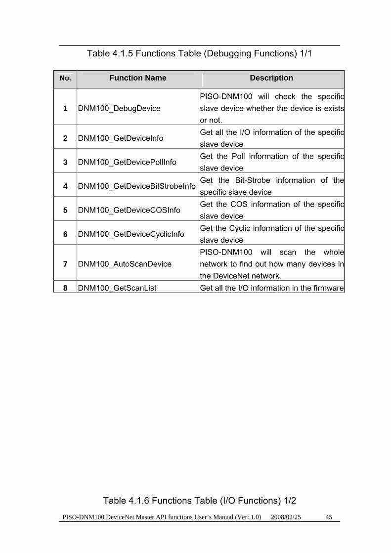
Table 4.1.5 Functions Table (Debugging Functions) 1/1 TNo. T TFunction NameT TDescriptionT
1 DNM100_DebugDevice PISO-DNM100 will check the specificslave device whether the device is existsor not.
2 DNM100_GetDeviceInfo Get all the I/O information of the specificslave device
3 DNM100_GetDevicePollInfo Get the Poll information of the specificslave device
4 DNM100_GetDeviceBitStrobeInfoGet the Bit-Strobe information of thespecific slave device
5 DNM100_GetDeviceCOSInfo Get the COS information of the specificslave device
6 DNM100_GetDeviceCyclicInfo Get the Cyclic information of the specificslave device
7 DNM100_AutoScanDevice PISO-DNM100 will scan the wholenetwork to find out how many devices inthe DeviceNet network.
8 DNM100_GetScanList Get all the I/O information in the firmware
Table 4.1.6 Functions Table (I/O Functions) 1/2

PISO-DNM100 DeviceNet Master API functions User’s Manual (Ver: 1.0) 2008/02/25 46
TNo. T TFunction NameT TDescriptionT
1 DNM100_GetExplicitStatus Get the Explicit connectionstatus of the slave device
2 DNM100_GetExplicitResult Get the Explicit connectionresult of the slave device
3 DNM100_GetAttribute Send the get attributecommand to the slave device.
4 DNM100_GetAttributeValue Get the attribute value of theDNM100_GetAttribute
5 DNM100_SetAttribute Send the set attributecommand to the slave device.
6 DNM100_SetAttributeResponse Get the response value of theDNM100_SetAttribute
7 DNM100_ReadPollInputData Read the input data via Pollconnection
8 DNM100_WritePollOutputData Write the output data via Pollconnection
9 DNM100_GetPollStatus Get the Poll connection statusof the slave device
10 DNM100_GetPollResult Get the Poll connection resultof the slave device
11 DNM100_CheckPollConnectionStatus Check the Poll connectionstatus is fine or not
12 DNM100_ReadBitStrobeInputData Read the input data viaBit-Strobe connection
13 DNM100_GetBitStrobeStatus Get the Bit-Strobe connectionstatus of the slave device
14 DNM100_GetBitStrobeResult Get the Bit-Strobe connectionresult of the slave device
15 DNM100_CheckBitStrobeConnectionStatusCheck the Bit-Strobeconnection status is fine or not
Table 4.1.7 Functions Table (I/O Functions) 2/2.

PISO-DNM100 DeviceNet Master API functions User’s Manual (Ver: 1.0) 2008/02/25 47
TNo. T TFunction NameT TDescriptionT
16 DNM100_ReadCOSInputData Read the input data via COSlconnection
17 DNM100_WriteCOSOutputData Write the output data via COSlconnection
18 DNM100_GetCOSStatus Get the COS connection statusof the slave device
19 DNM100_GetCOSResult Get the COS connection resultof the slave device
20 DNM100_CheckCOSConnectionStatus Check the COS connectionstatus is fine or not
21 DNM100_ReadCyclicInputData Read the input data via Cycliclconnection
22 DNM100_WriteCyclicOutputData Write the output data via Cycliclconnection
23 DNM100_GetCyclicStatus Get the Cyclic connectionstatus of the slave device
24 DNM100_GetCyclicResult Get the Cyclic connection resultof the slave device
25 DNM100_CheckCyclicConnectionStatus Check the Cyclic connectionstatus is fine or not
PISO-DNM100 DeviceNet Master API functions User’s Manual (Ver: 1.0) 2008/02/25 48
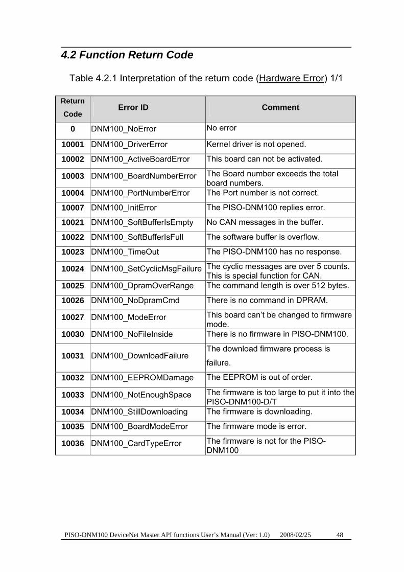
4.2 Function Return Code
Table 4.2.1 Interpretation of the return code (UHardware Error U) 1/1
TReturn
Code T
TError IDT TComment T
T0T DNM100_NoError No error
T10001T DNM100_DriverError Kernel driver is not opened.
T10002T DNM100_ActiveBoardError This board can not be activated.
T10003T DNM100_BoardNumberError The Board number exceeds the total board numbers.
T10004T DNM100_PortNumberError The Port number is not correct.
T10007T DNM100_InitError The PISO-DNM100 replies error.
T10021T DNM100_SoftBufferIsEmpty No CAN messages in the buffer.
T10022T DNM100_SoftBufferIsFull The software buffer is overflow.
T10023T DNM100_TimeOut The PISO-DNM100 has no response.
T10024T DNM100_SetCyclicMsgFailure The cyclic messages are over 5 counts. This is special function for CAN.
T10025T DNM100_DpramOverRange The command length is over 512 bytes.
T10026T DNM100_NoDpramCmd There is no command in DPRAM.
T10027T DNM100_ModeError This board can’t be changed to firmware mode.
T10030T DNM100_NoFileInside There is no firmware in PISO-DNM100.
T10031T DNM100_DownloadFailure The download firmware process is
failure.
T10032T DNM100_EEPROMDamage The EEPROM is out of order.
T10033T DNM100_NotEnoughSpace The firmware is too large to put it into the PISO-DNM100-D/T
T10034T DNM100_StillDownloading The firmware is downloading.
T10035T DNM100_BoardModeError TThe firmware mode is error. T
T10036T DNM100_CardTypeError TThe firmware is not for the PISO-DNM100 T

PISO-DNM100 DeviceNet Master API functions User’s Manual (Ver: 1.0) 2008/02/25 49
Table 4.2.2 Interpretation of the return code (MapTable Error) 1/1
TReturn Code T
TMapTable Error T TComment T
T1200T DNMXS_MapTableFull The MapTable is full.
T1201T DNMXS_MapDataDuplicate The data already exists in the MapTable.
T1202T DNMXS_MapDataNotFound The data can't be found in the MapTable.
T1203T DNMXS_MapTableError The MapTable has some errors.
Table 4.2.3 Interpretation of the return code (DeviceNet Error) 1/1
TReturn Code T
TDeviceNet ErrorT TComment T
T1300T DNMXS_BoardNotOnline The master is not on line.
T1301T DNMXS_ExplicitNotEstablish The Explicit connection is not established.
T1302T DNMXS_PollNotEstablish The Poll connection is not established.
T1303T DNMXS_BitStrobeNotEstablish The Bit-Strobe connection is not established.
T1304T DNMXS_COSNotEstablish The COS connection is not established.
T1305T DNMXS_CyclicNotEstablish The Cyclic connection is not established.
PISO-DNM100 DeviceNet Master API functions User’s Manual (Ver: 1.0) 2008/02/25 50
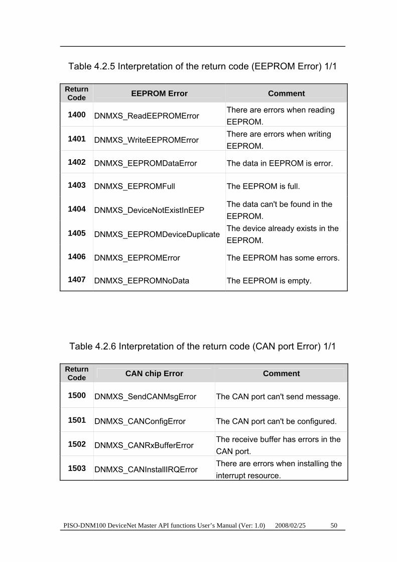
Table 4.2.5 Interpretation of the return code (EEPROM Error) 1/1
TReturn Code T
TEEPROM ErrorT TComment T
T1400T DNMXS_ReadEEPROMError There are errors when reading EEPROM.
T1401T DNMXS_WriteEEPROMError There are errors when writing EEPROM.
T1402T DNMXS_EEPROMDataError The data in EEPROM is error.
T1403T DNMXS_EEPROMFull The EEPROM is full.
T1404T DNMXS_DeviceNotExistInEEP The data can't be found in the EEPROM.
T1405T DNMXS_EEPROMDeviceDuplicate The device already exists in the EEPROM.
T1406T DNMXS_EEPROMError The EEPROM has some errors.
T1407T DNMXS_EEPROMNoData The EEPROM is empty.
Table 4.2.6 Interpretation of the return code (CAN port Error) 1/1
TReturn Code T
TCAN chip ErrorT TComment T
T1500T DNMXS_SendCANMsgError The CAN port can't send message.
T1501T DNMXS_CANConfigError The CAN port can't be configured.
T1502T DNMXS_CANRxBufferError The receive buffer has errors in the CAN port.
T1503T DNMXS_CANInstallIRQError There are errors when installing the interrupt resource.

PISO-DNM100 DeviceNet Master API functions User’s Manual (Ver: 1.0) 2008/02/25 51
Table 4.2.7 Interpretation of the return code (Functional Error) 1/3
TReturn Code T
TFunctional ErrorT TComment T
T1600T DNMXS_OnlineError [Note1]
T1700T DNMXS_ConnectionTypeNotSupport The connection type is not a valid I/O connection.
T1800T DNMXS_BitStrobeAlreadyExistInEEP The Bit-Strobe information already exists in the EEPROM.
T1900T DNMXS_PollAlreadyExistInEEP The Poll information already exists in the EEPROM.
T2000T DNMXS_COSAlreadyExistInEEP The COS information already exists in the EEPROM.
T2100T DNMXS_CyclicAlreadyExistInEEP The Cyclic information already exists in the EEPROM.
T2200T DNMXS_PollOutputDataLenError The output length of the Poll connection doesn't match the device's output length.
T2300T DNMXS_COSOutputDataLenError The output length of the COS connection doesn't match the device's output length.
T2400T DNMXS_CyclicOutputDataLenError The output length of the Cyclic connection doesn't match the device's output length.
[Note1]: The master MAC ID collides with other slave device in the DeviceNet
network.
PISO-DNM100 DeviceNet Master API functions User’s Manual (Ver: 1.0) 2008/02/25 52
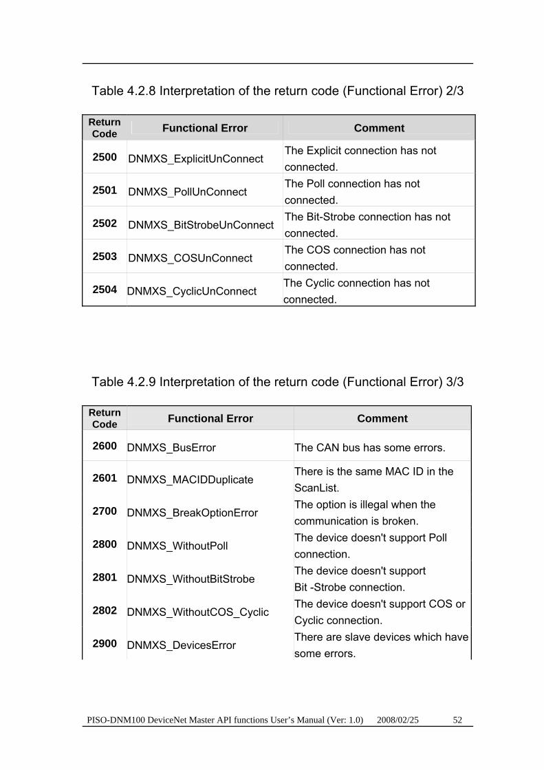
Table 4.2.8 Interpretation of the return code (Functional Error) 2/3
TReturn Code T
TFunctional ErrorT TComment T
T2500T DNMXS_ExplicitUnConnect The Explicit connection has not connected.
T2501T DNMXS_PollUnConnect The Poll connection has not connected.
T2502T DNMXS_BitStrobeUnConnect The Bit-Strobe connection has not connected.
T2503T DNMXS_COSUnConnect The COS connection has not connected.
T2504T DNMXS_CyclicUnConnect The Cyclic connection has not connected.
Table 4.2.9 Interpretation of the return code (Functional Error) 3/3
TReturn Code T
TFunctional ErrorT TComment T
T2600T DNMXS_BusError The CAN bus has some errors.
T2601T DNMXS_MACIDDuplicate There is the same MAC ID in the ScanList.
T2700T DNMXS_BreakOptionError The option is illegal when the communication is broken.
T2800T DNMXS_WithoutPoll The device doesn't support Poll connection.
T2801T DNMXS_WithoutBitStrobe The device doesn't support Bit -Strobe connection.
T2802T DNMXS_WithoutCOS_Cyclic The device doesn't support COS or Cyclic connection.
T2900T DNMXS_DevicesError There are slave devices which have some errors.
PISO-DNM100 DeviceNet Master API functions User’s Manual (Ver: 1.0) 2008/02/25 53
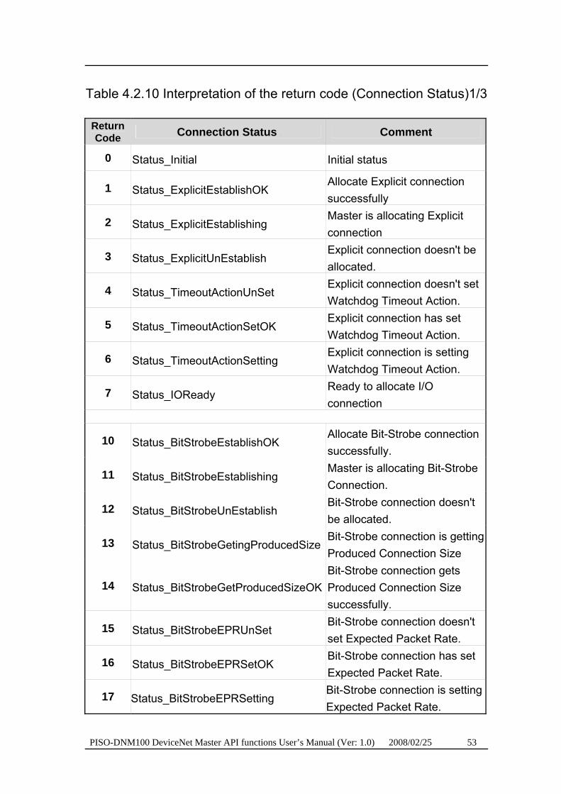
Table 4.2.10 Interpretation of the return code (Connection Status)1/3
TReturn Code T
TConnection Status T TComment T
T0T Status_Initial Initial status
T1T Status_ExplicitEstablishOK Allocate Explicit connection successfully
T2T Status_ExplicitEstablishing Master is allocating Explicit connection
T3T Status_ExplicitUnEstablish Explicit connection doesn't be allocated.
T4T Status_TimeoutActionUnSet Explicit connection doesn't set Watchdog Timeout Action.
T5T Status_TimeoutActionSetOK Explicit connection has set Watchdog Timeout Action.
T6T Status_TimeoutActionSetting Explicit connection is setting Watchdog Timeout Action.
T7T Status_IOReady Ready to allocate I/O connection
T10T Status_BitStrobeEstablishOK Allocate Bit-Strobe connection successfully.
T11T Status_BitStrobeEstablishing Master is allocating Bit-Strobe Connection.
T12T Status_BitStrobeUnEstablish Bit-Strobe connection doesn't be allocated.
T13T Status_BitStrobeGetingProducedSize Bit-Strobe connection is getting Produced Connection Size
T14T Status_BitStrobeGetProducedSizeOK Bit-Strobe connection gets Produced Connection Size successfully.
T15T Status_BitStrobeEPRUnSet Bit-Strobe connection doesn't set Expected Packet Rate.
T16T Status_BitStrobeEPRSetOK Bit-Strobe connection has set Expected Packet Rate.
T17T Status_BitStrobeEPRSetting Bit-Strobe connection is setting Expected Packet Rate.

PISO-DNM100 DeviceNet Master API functions User’s Manual (Ver: 1.0) 2008/02/25 54
Table 4.2.11 Interpretation of the return code (Connection Status)2/3
TReturn Code T
TConnection Status T TComment T
T20T Status_PollEstablishOK Allocate Poll connection successfully
T21T Status_PollEstablishing Master is allocating Poll connection.
T22T Status_PollUnEstablish Poll connection doesn't be allocated.
T23T Status_PollGetingProducedSize Poll connection is getting Produced Connection Size.
T24T Status_PollGetProducedSizeOK Poll connection gets Produced Connection Size successfully.
T25T Status_PollGetingConsumedSize Poll connection is getting Consumed Connection Size
T26T Status_PollGetConsumedSizeOK Poll connection gets Consumed Connection Size successfully.
T27T Status_PollEPRUnSet Poll connection doesn't set Expected Packet Rate.
T28T Status_PollEPRSetOK Poll connection has set Expected Packet Rate successfully.
T29T Status_PollEPRSetting Poll connection is setting Expected Packet Rate.
PISO-DNM100 DeviceNet Master API functions User’s Manual (Ver: 1.0) 2008/02/25 55
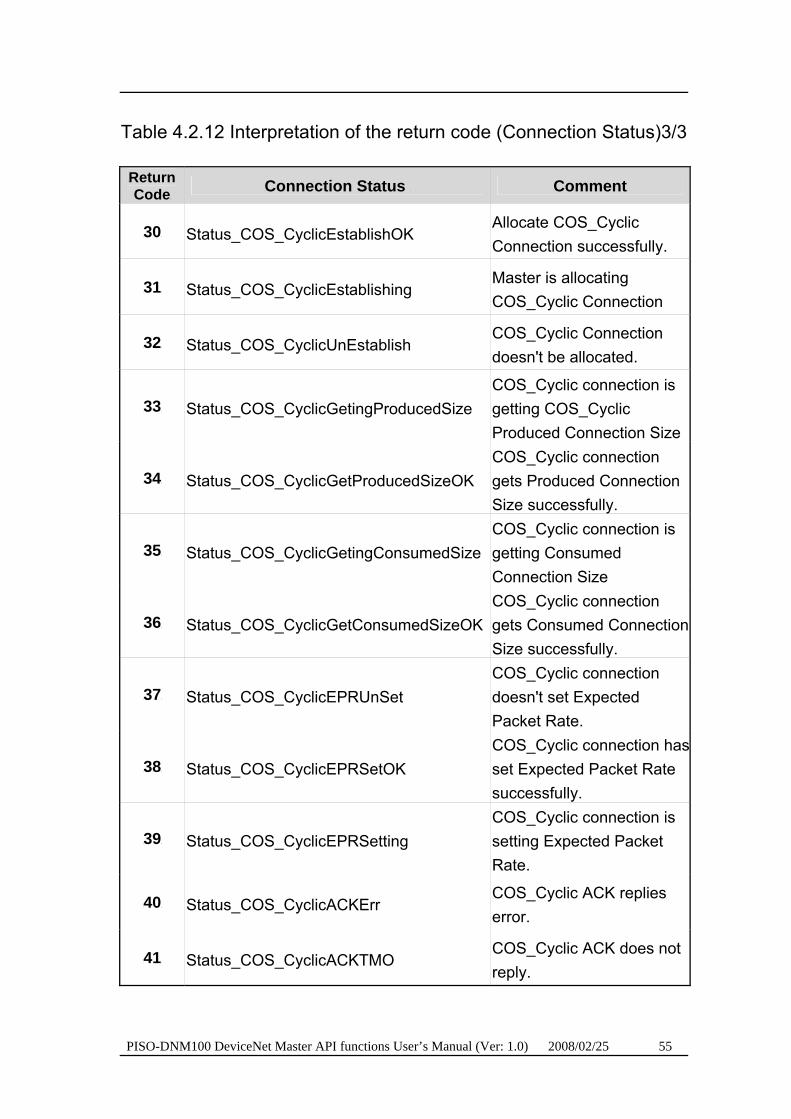
Table 4.2.12 Interpretation of the return code (Connection Status)3/3
TReturn Code T
TConnection Status T TComment T
T30T Status_COS_CyclicEstablishOK Allocate COS_Cyclic Connection successfully.
T31T Status_COS_CyclicEstablishing Master is allocating COS_Cyclic Connection
T32T Status_COS_CyclicUnEstablish COS_Cyclic Connection doesn't be allocated.
T33T Status_COS_CyclicGetingProducedSize COS_Cyclic connection is getting COS_Cyclic Produced Connection Size
T34T Status_COS_CyclicGetProducedSizeOK COS_Cyclic connection gets Produced Connection Size successfully.
T35T Status_COS_CyclicGetingConsumedSize COS_Cyclic connection is getting Consumed Connection Size
T36T Status_COS_CyclicGetConsumedSizeOK COS_Cyclic connection gets Consumed Connection Size successfully.
T37T Status_COS_CyclicEPRUnSet COS_Cyclic connection doesn't set Expected Packet Rate.
T38T Status_COS_CyclicEPRSetOK COS_Cyclic connection hasset Expected Packet Rate successfully.
T39T Status_COS_CyclicEPRSetting COS_Cyclic connection is setting Expected Packet Rate.
T40T Status_COS_CyclicACKErr COS_Cyclic ACK replies error.
T41T Status_COS_CyclicACKTMO COS_Cyclic ACK does not reply.

PISO-DNM100 DeviceNet Master API functions User’s Manual (Ver: 1.0) 2008/02/25 56
Table 4.2.13 Interpretation of the return code (Connection Result)1/5
TReturn Code T
TConnection Result T TComment T
T0T Result_None None
T1T Result_AllocateResOK Allocation replies OK.
T2T Result_AllocateResERR Allocation replies error.
T3T Result_AllocateResTMO Allocation replies timeout.
T4T Result_SetActionResOK Setting Watchdog Timeout Action is OK.
T5T Result_SetActionResERR Setting Watchdog Timeout Action responses error.
T6T Result_SetActionResTMO Setting Watchdog Timeout Action responses timeout.
T7T Result_ReleaseResOK Releasing connection responses OK.
T8T Result_ReleaseResERR Releasing connection responses error.
T9T Result_ReleaseResTMO Releasing connection responses timeout.
T10T Result_GetAttrResOK Getting Attribute is OK.
T11T Result_GetAttrResERR Getting Attribute is error.
T12T Result_GetAttrResTMO Getting Attribute is timeout.
T13T Result_SetAttrResOK Setting Attribute is OK.
T14T Result_SetAttrResERR Setting Attribute is error.
T15T Result_SetAttrResTMO Setting Attribute is timeout.
T16T Result_SetAttrACKTMO Setting Attribute ACK is timeout.
PISO-DNM100 DeviceNet Master API functions User’s Manual (Ver: 1.0) 2008/02/25 57
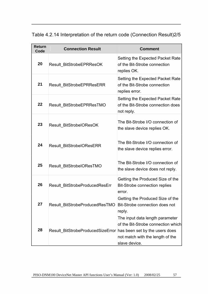
Table 4.2.14 Interpretation of the return code (Connection Result)2/5
TReturn Code T
TConnection Result T TComment T
T20T Result_BitStrobeEPRResOK Setting the Expected Packet Rate of the Bit-Strobe connection replies OK.
T21T Result_BitStrobeEPRResERR Setting the Expected Packet Rate of the Bit-Strobe connection replies error.
T22T Result_BitStrobeEPRResTMO Setting the Expected Packet Rate of the Bit-Strobe connection does not reply.
T23T Result_BitStrobeIOResOK The Bit-Strobe I/O connection of the slave device replies OK.
T24T Result_BitStrobeIOResERR The Bit-Strobe I/O connection of the slave device replies error.
T25T Result_BitStrobeIOResTMO The Bit-Strobe I/O connection of the slave device does not reply.
T26T Result_BitStrobeProducedResErr Getting the Produced Size of the Bit-Strobe connection replies error.
T27T Result_BitStrobeProducedResTMO Getting the Produced Size of the Bit-Strobe connection does not reply.
T28T Result_BitStrobeProducedSizeError
The input data length parameter of the Bit-Strobe connection which has been set by the users does not match with the length of the slave device.
PISO-DNM100 DeviceNet Master API functions User’s Manual (Ver: 1.0) 2008/02/25 58
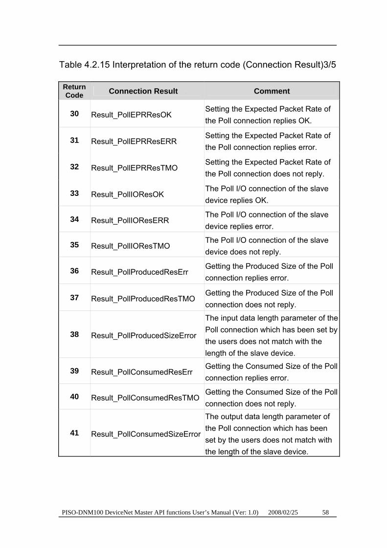
Table 4.2.15 Interpretation of the return code (Connection Result)3/5
TReturn Code T
TConnection Result T TComment T
T30T Result_PollEPRResOK Setting the Expected Packet Rate of the Poll connection replies OK.
T31T Result_PollEPRResERR Setting the Expected Packet Rate of the Poll connection replies error.
T32T Result_PollEPRResTMO Setting the Expected Packet Rate of the Poll connection does not reply.
T33T Result_PollIOResOK The Poll I/O connection of the slave device replies OK.
T34T Result_PollIOResERR The Poll I/O connection of the slave device replies error.
T35T Result_PollIOResTMO The Poll I/O connection of the slave device does not reply.
T36T Result_PollProducedResErr Getting the Produced Size of the Poll connection replies error.
T37T Result_PollProducedResTMO Getting the Produced Size of the Poll connection does not reply.
T38T Result_PollProducedSizeError
The input data length parameter of the Poll connection which has been set by the users does not match with the length of the slave device.
T39T Result_PollConsumedResErr Getting the Consumed Size of the Poll connection replies error.
T40T Result_PollConsumedResTMO Getting the Consumed Size of the Poll connection does not reply.
T41T Result_PollConsumedSizeError
The output data length parameter of the Poll connection which has been set by the users does not match with the length of the slave device.

PISO-DNM100 DeviceNet Master API functions User’s Manual (Ver: 1.0) 2008/02/25 59
Table 4.2.16 Interpretation of the return code (Connection Result)4/5
TReturn Code T
TConnection Result T TComment T
T53T Result_COS_CyclicEPRResOK Setting the Expected Packet Rate of COS_Cyclic connection replies OK.
T54T Result_COS_CyclicEPRResERR Setting the Expected Packet Rate of COS_Cyclic connection replies error.
T55T Result_COS_CyclicEPRResTMO Setting the Expected Packet Rate of COS_Cyclic connection does not reply.
T56T Result_COS_CyclicIOResOK The COS_Cyclic I/O connection replies OK.
T57T Result_COS_CyclicIOResERR The COS_Cyclic I/O connection replies error.
T58T Result_COS_CyclicIOResTMO The COS_Cyclic I/O connection does not reply.
T59T Result_COS_CyclicACKResOK The COS_Cyclic ACK replies OK.
T60T Result_COS_CyclicACKResERR The COS_Cyclic ACK replies error.
T61T Result_COS_CyclicACKResTMO The COS_Cyclic ACK does not reply.

PISO-DNM100 DeviceNet Master API functions User’s Manual (Ver: 1.0) 2008/02/25 60
Table 4.2.17 Interpretation of the return code (Connection Result)5/5
TReturn Code T
TConnection Result T TComment T
T62T Result_COS_CyclicProducedResErr Getting the Produced Size of the COS_Cyclic connection replies error.
T63T Result_COS_CyclicProducedResTMO Getting the Produced Size of the COS_Cyclic connection does not reply.
T64T Result_COS_CyclicProducedSizeError
The input data length parameter of the COS_Cyclic connection which has been set by the users does not match with the length of the slave device.
T65T Result_COS_CyclicConsumedResErr Getting the Consumed Size of the COS_Cyclic connection replies error.
T66T Result_COS_CyclicConsumedResTMO Getting the Consumed Size of the COS_Cyclic connection does not reply.
T67T Result_COS_CyclicConsumedSizeError
The output data length parameter of the COS_Cyclic connection which has been set by the users does not match with the length of the slave device.
T70TTT Result_ModuleNoResponse Slave Module doesn’t response
PISO-DNM100 DeviceNet Master API functions User’s Manual (Ver: 1.0) 2008/02/25 61
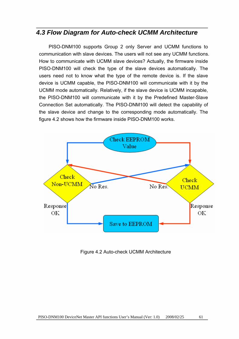
4.3 Flow Diagram for Auto-check UCMM Architecture
PISO-DNM100 supports Group 2 only Server and UCMM functions to communication with slave devices. The users will not see any UCMM functions. How to communicate with UCMM slave devices? Actually, the firmware inside PISO-DNM100 will check the type of the slave devices automatically. The users need not to know what the type of the remote device is. If the slave device is UCMM capable, the PISO-DNM100 will communicate with it by the UCMM mode automatically. Relatively, if the slave device is UCMM incapable, the PISO-DNM100 will communicate with it by the Predefined Master-Slave Connection Set automatically. The PISO-DNM100 will detect the capability of the slave device and change to the corresponding mode automatically. The figure 4.2 shows how the firmware inside PISO-DNM100 works.
Figure 4.2 Auto-check UCMM Architecture
PISO-DNM100 DeviceNet Master API functions User’s Manual (Ver: 1.0) 2008/02/25 62
4.4 Function Description
4.4.1 DNM100_GetBoardInf
Description:
This function is used to obtain the driver information of PISO-DNM100 board.
Syntax:
DWORD DNM100_GetBoardInf (BYTE BoardNo, DWORD *dwVID, DWORD *dwDID, DWORD *dwSVID, DWORD *dwSDID, DWORD *dwSAuxID, DWORD *dwIrqNo)
Parameter:
BoardNo: [input] PISO-DNM100 board number (0~15) dwVID: [output] The address of a variable which is used to receive the
vendor ID. dwDID: [output] The address of a variable used to receive device ID. dwSVID: [output] The address of a variable applied to receive
sub-vendor ID. dwSDID: [output] The address of a variable applied to receive
sub-device ID. dwSAuxID: [output] The address of a variable used to receive
sub-auxiliary ID. dwIrqNo: [output] The address of a variable used to receive logical
interrupt number.
Return:
DNM100_NoError (0): OK DNM100_DriverError (10001): Kernel driver is not opened. DNM100_BoardNumberError (10003): BoardNo exceeds the current
scanned total board number.

PISO-DNM100 DeviceNet Master API functions User’s Manual (Ver: 1.0) 2008/02/25 63
4.4.2 DNM100_TotalDNM100Board
Description:
The function can get the count of total PISO-DNM100 boards in the user’s PC.
Syntax:
DWORD DNM100_TotalDNM100Board (BYTE *TotalBoards, BYTE *BoardIDList);
Parameter:
TotalBoards: [output] The count of total board. BoardIDList: [output] The list of all DIP-Switch No. in each board.
Return:
DNM100_NoError (0): OK DNM100_DriverError (10001): Kernel driver is not opened.
PISO-DNM100 DeviceNet Master API functions User’s Manual (Ver: 1.0) 2008/02/25 64
4.4.3 DNM100_ActiveBoard
Description: The function is used to activate PISO-DNM100-D/T. It must be called
once before using the other functions of PISO-DNM100-D/T APIs.
Syntax:
DWORD DNM100_ActiveBoard (BYTE BoardNo)
Parameter:
BoardNo: [input] PISO-DNM100 board number (0~15)
Return:
DNM100_NoError (0): OK DNM100_DriverError (10001): Kernel driver is not opened. DNM100_ActiveBoardError (10002): This board can not be activated or
kernel driver can not be found. DNM100_BoardNumberError (10003): BoardNo exceeds the current
scanned total board number.
PISO-DNM100 DeviceNet Master API functions User’s Manual (Ver: 1.0) 2007/12/7 65
4.4.4 DNM100_CloseBoard
Description: The function is used to stop and close the kernel driver and release
the device resource from computer device resource. This method must be called once before exiting the user’s application program.
Syntax: DWORD DNM100_CloseBoard (BYTE BoardNo)
Parameter: BoardNo: [input] PISO-DNM100 board number (0~15)
Return: DNM100_NoError (0): OK DNM100_DriverError (10001): Kernel driver is not opened.
DNM100_BoardNumberError (10003): BoardNo exceeds the current scanned total board number.
PISO-DNM100 DeviceNet Master API functions User’s Manual (Ver: 1.0) 2008/02/25 66
4.4.5 DNM100_GetDLLVersion
Description: The function can obtain the version information of DNM100.dll driver.
Syntax: DWORD DNM100_GetDLLVersion (void)
Parameter: None
Return: The DLL version information. For example: If 100(hex) is return, it
means driver version is 1.00.

PISO-DNM100 DeviceNet Master API functions User’s Manual (Ver: 1.0) 2008/02/25 67
4.4.6 DNM100_GetFirmwareVersion
Description:
The function can obtain the version information of the firmware inside PISO-DNM100.
Syntax:
DWORD DNM100_GetFirmwareVersion (BYTE BoardNo)
Parameter:
BoardNo: [input] PISO-DNM100 board number (0~15)
Return:
The firmware version information. For example: If 100(hex) is return, it means firmware version is 1.00.
Error Return:
DNM100_NoError (0): OK DNM100_DriverError (10001): Kernel driver is not opened. DNM100_ActiveBoardError (10002): This board can not be activated or
kernel driver can not be found. DNM100_BoardNumberError (10003): BoardNo exceeds the current
scanned total board number. DNM100_TimeOut (10023): The PISO-DNM100 has no response.
PISO-DNM100 DeviceNet Master API functions User’s Manual (Ver: 1.0) 2008/02/25 68
4.4.7 DNM100_ResetFirmware
Description:
The function is used to reset the PISO-DNM100 firmware. When the users have changed the baud rate of CAN bus or changed the Master’s MAC ID, the function must be called to make the change enable. After calling this function, the users should wait for 1 or 2 seconds to make the firmware boot up completely.
Syntax:
DWORD DNM100_ResetFirmware (BYTE BoardNo)
Parameter:
BoardNo: [input] PISO-DNM100 board number (0~15)
Return:
DNM100_NoError (0): OK DNM100_DriverError (10001): Kernel driver is not opened. DNM100_ActiveBoardError (10002): This board can not be activated or
kernel driver can not be found. DNM100_BoardNumberError (10003): BoardNo exceeds the current
scanned total board number. DNM100_TimeOut (10023): The PISO-DNM100 has no response. DNM100_ModeError (10027): This board is in download mode, and can’t
be changed to firmware mode.
PISO-DNM100 DeviceNet Master API functions User’s Manual (Ver: 1.0) 2008/02/25 69
4.4.8 DNM100_CheckFirmwareMode
Description:
The function is used to obtain the specified PISO-DNM100-D/T if it is in download mode or firmware mode.
Syntax:
DWORD DNM100_CheckFirmwareMode (BYTE BoardNo, BYTE *Mode)
Parameter:
BoardNo: [input] PISO-DNM100 board number (0~15) Mode: [output] The address of a variable used to get the PISO-DNM100-
D/T mode. If this value is 0, it indicates that the PISO-DNM100-D/T is in download mode. If 1, it is in firmware mode. When PISO-DNM100-D/T is in download mode, it can only update the firmware and the firmware will not work at the same time.
Return:
DNM100_NoError (0): OK DNM100_DriverError (10001): Kernel driver is not opened. DNM100_ActiveBoardError (10002): This board can not be activated or
kernel driver can not be found. DNM100_BoardNumberError (10003): BoardNo exceeds the current
scanned total board number. DNM100_InitError (10007): The PISO-DNM100 replies erroneously. DNM100_TimeOut (10023): The PISO-DNM100 has no response. DNM100_ModeError (10027): This board is in download mode, and can’t
be changed to firmware mode.
PISO-CAN400/200 DeviceNet Master Library User’s Manual (Ver: 1.0) 70
4.4.9 DNM100_GetMasterMACID
Description:
The function can get the MAC ID of the DeviceNet master (PISO-DNM100).
Syntax:
DWORD DNM100_GetMasterMACID (BYTE BoardNo)
Parameter:
BoardNo: [input] PISO-DNM100 board number (0~15)
Return:
The Master's MAC ID. (0 ~ 63)
Error Return:
DNM100_NoError (0): OK DNM100_DriverError (10001): Kernel driver is not opened. DNM100_ActiveBoardError (10002): This board can not be activated or
kernel driver can not be found. DNM100_BoardNumberError (10003): BoardNo exceeds the current
scanned total board number. DNM100_TimeOut (10023): The PISO-DNM100 has no response. Others: Please refer to Table 4.2.2 ~ Table 4.2.9.

PISO-DNM100 DeviceNet Master API functions User’s Manual (Ver: 1.0) 2008/02/25 71
4.4.10 DNM100_SetMasterMACID
Description:
The function can set the MAC ID of the DeviceNet master (PISO-DNM100). After calling this function, the users must call DNM100_ResetFirmware to make the change enabled. It will save the information in the EEPROM in PISO-DNM100.
Syntax:
DWORD DNM100_SetMasterMACID (BYTE BoardNo, BYTE MasterMACID)
Parameter:
BoardNo: [input] PISO-DNM100 board number (0~15) MasterMACID: [input] The DeviceNet master’s MAC ID (0~63)
Return:
DNM100_NoError (0): OK DNM100_DriverError (10001): Kernel driver is not opened. DNM100_ActiveBoardError (10002): This board can not be activated or
kernel driver can not be found. DNM100_BoardNumberError (10003): BoardNo exceeds the current
scanned total board number. DNM100_TimeOut (10023): The PISO-DNM100 has no response. Others: Please refer to Table 4.2.2 ~ Table 4.2.9.
PISO-DNM100 DeviceNet Master API functions User’s Manual (Ver: 1.0) 2008/02/25 72
4.4.11 DNM100_GetBaudRate
Description:
This function can help you to get the baud rate information of PISO-DNM100.
Syntax:
DWORD DNM100_GetBaudRate (BYTE BoardNo)
Parameter:
BoardNo: [input] PISO-DNM100 board number (0~15)
Return:
The baud rate information in the PISO-DNM100. If the value is 0, the baud rate is 125Kbps. If the value is 1, the baud rate is 250Kbps. If the value is 2, the baud rate is 500Kbps.
Error Return:
DNM100_NoError (0): OK DNM100_DriverError (10001): Kernel driver is not opened. DNM100_ActiveBoardError (10002): This board can not be activated or
kernel driver can not be found. DNM100_BoardNumberError (10003): BoardNo exceeds the current
scanned total board number. DNM100_TimeOut (10023): The PISO-DNM100 has no response. Others: Please refer to Table 4.2.2 ~ Table 4.2.9.

PISO-DNM100 DeviceNet Master API functions User’s Manual (Ver: 1.0) 2008/02/25 73
4.4.12 DNM100_SetBaudRate
Description:
This function can set the DeviceNet baud rate of the PISO-DNM100. After calling this function, you must call DNM100_ResetFirmware to reset the firmware to make change enabled.
Syntax:
DWORD DNM100_SetBaudRate (BYTE BoardNo, BYTE BaudRate)
Parameter:
BoardNo: [input] PISO-DNM100 board number (0~15) BaudRate: [input] The new baud rate value. 0 : 125K bps 1 : 250K bps 2 : 500K bps
Return:
DNM100_NoError (0): OK DNM100_DriverError (10001): Kernel driver is not opened. DNM100_ActiveBoardError (10002): This board can not be activated or
kernel driver can not be found. DNM100_BoardNumberError (10003): BoardNo exceeds the current
scanned total board number. DNM100_TimeOut (10023): The PISO-DNM100 has no response. Others: Please refer to Table 4.2.2 ~ Table 4.2.9.

PISO-DNM100 DeviceNet Master API functions User’s Manual (Ver: 1.0) 2008/01/21 74
4.4.13 DNM100_GetMasterStatus
Description:
The function is used to obtain the firmware status inside PISO-DNM100. The users can call this function to make sure that the DeviceNet master is online successfully.
Syntax:
DWORD DNM100_GetMasterStatus (BYTE BoardNo)
Parameter:
BoardNo: [input] PISO-DNM100 board number (0~15)
Return:
DNM100_NoError (0): OK DNM100_DriverError (10001): Kernel driver is not opened. DNM100_ActiveBoardError (10002): This board can not be activated or
kernel driver can not be found. DNM100_BoardNumberError (10003): BoardNo exceeds the current
scanned total board number. DNM100_TimeOut (10023): The PISO-DNM100 has no response. Others: Please refer to Table 4.2.2 ~ Table 4.2.9.
PISO-DNM100 DeviceNet Master API functions User’s Manual (Ver: 1.0) 2008/02/25 75
4.4.14 DNM100_StartDevice
Description:
This function is used to start to communicate with the specific device that the users applying.
Syntax:
DWORD DNM100_StartDevice (BYTE BoardNo,BYTE DesMACID)
Parameter:
BoardNo: [input] PISO-DNM100 board number (0~15) DestMACID: [input] The remote slave device’s MAC ID (0~63)
Return:
DNM100_NoError (0): OK DNM100_DriverError (10001): Kernel driver is not opened. DNM100_ActiveBoardError (10002): This board can not be activated or
kernel driver can not be found. DNM100_BoardNumberError (10003): BoardNo exceeds the current
scanned total board number. DNM100_TimeOut (10023): The PISO-DNM100 has no response. Others: Please refer to Table 4.2.2 ~ Table 4.2.9.

PISO-DNM100 DeviceNet Master API functions User’s Manual (Ver: 1.0) 2008/02/25 76
4.4.15 DNM100_StopDevice
Description:
This function is used to stop to communicate with the destination device that the users appointed.
Syntax:
DWORD DNM100_StopDevice (BYTE BoardNo, BYTE DesMACID)
Parameter:
BoardNo: [input] PISO-DNM100 board number (0~15) DestMACID: [input] The remote slave device’s MAC ID (0~63)
Return:
DNM100_NoError (0): OK DNM100_DriverError (10001): Kernel driver is not opened. DNM100_ActiveBoardError (10002): This board can not be activated or
kernel driver can not be found. DNM100_BoardNumberError (10003): BoardNo exceeds the current
scanned total board number. DNM100_TimeOut (10023): The PISO-DNM100 has no response. Others: Please refer to Table 4.2.2 ~ Table 4.2.9.

PISO-DNM100 DeviceNet Master API functions User’s Manual (Ver: 1.0) 2008/02/25 77
4.4.16 DNM100_StartAllDevice
Description:
This function is used to start to communicate with all slave devices in ScanList.
Syntax:
DWORD DNM100_StartAllDevice (BYTE BoardNo)
Parameter:
BoardNo: [input] PISO-DNM100 board number (0~15)
Return:
DNM100_NoError (0): OK DNM100_DriverError (10001): Kernel driver is not opened. DNM100_ActiveBoardError (10002): This board can not be activated or
kernel driver can not be found. DNM100_BoardNumberError (10003): BoardNo exceeds the current
scanned total board number. DNM100_TimeOut (10023): The PISO-DNM100 has no response. Others: Please refer to Table 4.2.2 ~ Table 4.2.9.
PISO-DNM100 DeviceNet Master API functions User’s Manual (Ver: 1.0) 2008/02/25 78
4.4.17 DNM100_StopAllDevice
Description:
This function is used to stop to communicate with all destination devices in ScanList.
Syntax:
DWORD DNM100_StopAllDevice (BYTE BoardNo)
Parameter:
BoardNo: [input] PISO-DNM100 board number (0~15)
Return:
DNM100_NoError (0): OK DNM100_DriverError (10001): Kernel driver is not opened. DNM100_ActiveBoardError (10002): This board can not be activated or
kernel driver can not be found. DNM100_BoardNumberError (10003): BoardNo exceeds the current
scanned total board number. DNM100_TimeOut (10023): The PISO-DNM100 has no response. Others: Please refer to Table 4.2.2 ~ Table 4.2.9.

PISO-DNM100 DeviceNet Master API functions User’s Manual (Ver: 1.0) 2008/02/25 79
4.4.18 DNM100_AddDevice
Description:
This function can add the slave devices into the ScanList of the PISO-DNM100 and save the information into the EEPROM. Before communicating with any slave devices, the users should call this function to add these devices.
Syntax:
DWORD DNM100_AddDevice (BYTE BoardNo, BYTE DesMACID, WORD Explicit_EPR)
Parameter:
BoardNo: [input] PISO-DNM100 board number (0~15) DestMACID: [input] The remote slave device’s MAC ID (0~63) Explicit_EPR: [input] The Expected Packet Rate. (Usually is 2500).
Return:
DNM100_NoError (0): OK DNM100_DriverError (10001): Kernel driver is not opened. DNM100_ActiveBoardError (10002): This board can not be activated or
kernel driver can not be found. DNM100_BoardNumberError (10003): BoardNo exceeds the current
scanned total board number. DNM100_TimeOut (10023): The PISO-DNM100 has no response. Others: Please refer to Table 4.2.2 ~ Table 4.2.9.
PISO-DNM100 DeviceNet Master API functions User’s Manual (Ver: 1.0) 2008/02/25 80
4.4.19 DNM100_RemoveDevice
Description:
This function is used for removing the specified slave device from the ScanList in the PISO-DNM100. And the information of the device in EEPROM is erased at the same time.
Syntax:
DWORD DNM100_RemoveDevice (BYTE BoardNo, BYTE DesMACID)
Parameter:
BoardNo: [input] PISO-DNM100 board number (0~15) DestMACID: [input] The remote slave device’s MAC ID (0~63)
Return:
DNM100_NoError (0): OK DNM100_DriverError (10001): Kernel driver is not opened. DNM100_ActiveBoardError (10002): This board can not be activated or
kernel driver can not be found. DNM100_BoardNumberError (10003): BoardNo exceeds the current
scanned total board number. DNM100_TimeOut (10023): The PISO-DNM100 has no response. Others: Please refer to Table 4.2.2 ~ Table 4.2.9.
PISO-DNM100 DeviceNet Master API functions User’s Manual (Ver: 1.0) 2008/02/25 81
4.4.20 DNM100_GetExplicitStatus
Description:
The function is used to check the Explicit Message Connection Status, which connects to the specific slave. After you have started the device, you can execute this function to check the connection’s status.
Syntax:
DWORD DNM100_GetExplicitStatus (BYTE BoardNo, BYTE DesMACID)
Parameter:
BoardNo: [input] PISO-DNM100 board number (0~15) DestMACID: [input] The remote slave device’s MAC ID (0~63)
Return:
DNM100_NoError (0): OK DNM100_DriverError (10001): Kernel driver is not opened. DNM100_ActiveBoardError (10002): This board can not be activated or
kernel driver can not be found. DNM100_BoardNumberError (10003): BoardNo exceeds the current
scanned total board number. DNM100_TimeOut (10023): The PISO-DNM100 has no response. Others: Please refer to Table 4.2.10 ~ Table 4.2.12.

PISO-DNM100 DeviceNet Master API functions User’s Manual (Ver: 1.0) 2008/02/25 82
4.4.21 DNM100_GetExplicitResult
Description:
This function is used to check the Explicit Connection result with the specific slave device.
Syntax:
DWORD DNM100_GetExplicitResult (BYTE BoardNo, BYTE DesMACID)
Parameter:
BoardNo: [input] PISO-DNM100 board number (0~15) DestMACID: [input] The remote slave device’s MAC ID (0~63)
Return:
DNM100_NoError (0): OK DNM100_DriverError (10001): Kernel driver is not opened. DNM100_ActiveBoardError (10002): This board can not be activated or
kernel driver can not be found. DNM100_BoardNumberError (10003): BoardNo exceeds the current
scanned total board number. DNM100_TimeOut (10023): The PISO-DNM100 has no response. Others: Please refer to Table 4.2.13 ~ Table 4.2.17.
PISO-DNM100 DeviceNet Master API functions User’s Manual (Ver: 1.0) 2008/02/25 83
4.4.22 DNM100_GetAttribute
Description:
This function is used to send the request command to retrieve the attribute value of the specific device’s instance. Before calling this function, you must start the device. After calling this function, you should execute the “DNM100_GetAttributeValue” to get the response message returned from remote slave device.
Syntax:
DWORD DNM100_GetAttribute (BYTE BoardNo, BYTE DesMACID, BYTE ClassID, BYTE InstanceID, BYTE AttributeID)
Parameter:
BoardNo: [input] PISO-DNM100 board number (0~15) DestMACID: [input] The remote slave device’s MAC ID (0~63) ClassID: [input] The remote slave device’s ClassID InstanceID: [input] The remote slave device’s InstanceID AttributeID: [input] The remote slave device’s AttributeID
Return:
DNM100_NoError (0): OK DNM100_DriverError (10001): Kernel driver is not opened. DNM100_ActiveBoardError (10002): This board can not be activated or
kernel driver can not be found. DNM100_BoardNumberError (10003): BoardNo exceeds the current
scanned total board number. DNM100_TimeOut (10023): The PISO-DNM100 has no response. Others: Please refer to Table 4.2.2 ~ Table 4.2.9.

PISO-DNM100 DeviceNet Master API functions User’s Manual (Ver: 1.0) 2008/02/25 84
4.4.23 DNM100_GetAttributeValue
Description:
This function is used to get the attribute value of the specific device’s instance, which returned from the remote slave device. Before calling this function, the users should call DNM100_GetAttribute to send request command first.
Syntax:
DWORD DNM100_GetAttributeValue (BYTE BoardNo, BYTE DesMACID, WORD *DataLen, BYTE *DATA)
Parameter:
BoardNo: [input] PISO-DNM100 board number (0~15) DestMACID: [input] The remote slave device’s MAC ID (0~63) DataLen: [output] The length of the attribute value (in byte). DATA: [output] The attribute value that returned from the slave device.
Return:
DNM100_NoError (0): OK DNM100_DriverError (10001): Kernel driver is not opened. DNM100_ActiveBoardError (10002): This board can not be activated or
kernel driver can not be found. DNM100_BoardNumberError (10003): BoardNo exceeds the current
scanned total board number. DNM100_TimeOut (10023): The PISO-DNM100 has no response. Others: Please refer to Table 4.2.2 ~ Table 4.2.9 and
Table 4.2.13 ~ Table 4.2.17.
PISO-DNM100 DeviceNet Master API functions User’s Manual (Ver: 1.0) 2008/02/25 85
4.4.24 DNM100_SetAttribute
Description:
The method is used to set the attribute of the specific device’s instance. Before calling this function, you must start the device. After calling this function, you should execute the “DNM100_SetAttributeResponse” to check the response message returned from the remote slave device.
Syntax:
DWORD DNM100_SetAttribute (BYTE BoardNo, BYTE DesMACID, BYTE ClassID, BYTE InstanceID, BYTE AttributeID, WORD DataLen, BYTE *DATA)
Parameter:
BoardNo: [input] PISO-DNM100 board number (0~15) DestMACID: [input] The remote slave device’s MAC ID (0~63) ClassID: [input] The remote slave device’s ClassID InstanceID: [input] The remote slave device’s InstanceID AttributeID: [input] The remote slave device’s AttributeID DataLen: [input] The length of the attribute value (in byte). DATA: [input] The attribute value that the users want to send.
Return:
DNM100_NoError (0): OK DNM100_DriverError (10001): Kernel driver is not opened. DNM100_ActiveBoardError (10002): This board can not be activated or
kernel driver can not be found. DNM100_BoardNumberError (10003): BoardNo exceeds the current
scanned total board number. DNM100_TimeOut (10023): The PISO-DNM100 has no response. Others: Please refer to Table 4.2.2 ~ Table 4.2.9
PISO-DNM100 DeviceNet Master API functions User’s Manual (Ver: 1.0) 2008/02/25 86
4.4.25 DNM100_SetAttributeResponse
Description:
This function is used to get the response value after executing the “DNM100_SetAttribute” function.
Syntax:
DWORD DNM100_SetAttributeResponse (BYTE BoardNo, BYTE DesMACID)
Parameter:
BoardNo: [input] PISO-DNM100 board number (0~15) DestMACID: [input] The remote slave device’s MAC ID (0~63)
Return:
DNM100_NoError (0): OK DNM100_DriverError (10001): Kernel driver is not opened. DNM100_ActiveBoardError (10002): This board can not be activated or
kernel driver can not be found. DNM100_BoardNumberError (10003): BoardNo exceeds the current
scanned total board number. DNM100_TimeOut (10023): The PISO-DNM100 has no response. Others: Please refer to Table 4.2.2 ~ Table 4.2.9 and
Table 4.2.13 ~ Table 4.2.17.
PISO-DNM100 DeviceNet Master API functions User’s Manual (Ver: 1.0) 2008/02/25 87
4.4.26 DNM100_RemoveIOConnection
Description:
The function is used to remove the I/O Connection configuration.
Syntax:
DWORD DNM100_RemoveIOConnection (BYTE BoardNo, BYTE DesMACID, BYTE Type)
Parameter:
BoardNo: [input] PISO-DNM100 board number (0~15) DestMACID: [input] The remote slave device’s MAC ID (0~63) Type: [input] The I/O Connection type. (1 ~ 4). 1 : Poll connection. 2 : Bit-Strobe connection. 3 : COS connection. 4 : Cyclic connection.
Return:
DNM100_NoError (0): OK DNM100_DriverError (10001): Kernel driver is not opened. DNM100_ActiveBoardError (10002): This board can not be activated or
kernel driver can not be found. DNM100_BoardNumberError (10003): BoardNo exceeds the current
scanned total board number. DNM100_TimeOut (10023): The PISO-DNM100 has no response. Others: Please refer to Table 4.2.2 ~ Table 4.2.9

PISO-DNM100 DeviceNet Master API functions User’s Manual (Ver: 1.0) 2008/02/25 88
4.4.27 DNM100_SetBreakOption
Description:
This function will change the re-connection mechanism when the slave device is broken.
Syntax:
DWORD DNM100_SetBreakOption (BYTE BoardNo, BYTE DesMACID, BYTE Option)
Parameter:
BoardNo: [input] PISO-DNM100 board number (0~15) DestMACID: [input] The remote slave device’s MAC ID (0~63) Option: [input] The option value when connection is broken. 0x00 : No re-connection mechanism. 0x01 : Re-Connect when I/O connection is broken. If the slave
device doesn't response or response error. The master (PISO-DNM100) will re-connect it. If the device was shut down then power on, the master will not re-connect it.
0x02 : Re-Connect when device was power on again. 0x03 : The combination of the 0x01 and 0x02. This is the default
value when the users add new devices into ScanList.
Return:
DNM100_NoError (0): OK DNM100_DriverError (10001): Kernel driver is not opened. DNM100_ActiveBoardError (10002): This board can not be activated or
kernel driver can not be found. DNM100_BoardNumberError (10003): BoardNo exceeds the current
scanned total board number. DNM100_TimeOut (10023): The PISO-DNM100 has no response. Others: Please refer to Table 4.2.2 ~ Table 4.2.9
PISO-DNM100 DeviceNet Master API functions User’s Manual (Ver: 1.0) 2008/02/25 89
4.4.28 DNM100_GetBreakOption
Description:
This function will get the option value when slave device connection is broken.
Syntax:
DWORD DNM100_GetBreakOption (BYTE BoardNo, BYTE DesMACID)
Parameter:
BoardNo: [input] PISO-DNM100 board number (0~15) DestMACID: [input] The remote slave device’s MAC ID (0~63)
Return:
The option value of the slave device. 0x00 : No re-connection mechanism. 0x01 : Re-Connect when I/O connection is broken. If the slave device
doesn't response or response error. The master (PISO-DNM100) will re-connect it. If the device was shut down then power on, the master will not re-connect it.
0x02 : Re-Connect when device was power on again. 0x03 : The combination of the 0x01 and 0x02. This is the default value
when the users add new device into ScanList.
Error Return:
DNM100_NoError (0): OK DNM100_DriverError (10001): Kernel driver is not opened. DNM100_ActiveBoardError (10002): This board can not be activated or
kernel driver can not be found. DNM100_BoardNumberError (10003): BoardNo exceeds the current
scanned total board number. DNM100_TimeOut (10023): The PISO-DNM100 has no response. Others: Please refer to Table 4.2.2 ~ Table 4.2.9
PISO-DNM100 DeviceNet Master API functions User’s Manual (Ver: 1.0) 2008/02/25 90
4.4.29 DNM100_ClearAllConfig
Description:
This function will clear all configurations in the EEPROM of the PISO-DNM100.
Syntax:
DWORD DNM100_ClearAllConfig (BYTE BoardNo)
Parameter:
BoardNo: [input] PISO-DNM100 board number (0~15)
Return:
DNM100_NoError (0): OK DNM100_DriverError (10001): Kernel driver is not opened. DNM100_ActiveBoardError (10002): This board can not be activated or
kernel driver can not be found. DNM100_BoardNumberError (10003): BoardNo exceeds the current
scanned total board number. DNM100_TimeOut (10023): The PISO-DNM100 has no response. Others: Please refer to Table 4.2.2 ~ Table 4.2.9
PISO-DNM100 DeviceNet Master API functions User’s Manual (Ver: 1.0) 2008/02/25 91
4.4.30 DNM100_GetLastDeviceError
Description:
This function will get the last error device in the network
Syntax:
DWORD DNM100_GetLastDeviceError (BYTE BoardNo, BYTE *Err_MACID, BYTE *Err_Type, BYTE *Err_Code)
Parameter:
BoardNo: [input] PISO-DNM100 board number (0~15) Err_MACID: [output] The error slave device's MAC ID. If there is no error
device, the value is FF (hex). Err_Type: [output] The connection type of the error slave device. If there
is no error device, the value is FF (hex). Err_Code: [output] The error code. If there is no error device, the value is
FF (hex). Please refer to Table 4.2.13 ~ Table 4.2.17
Return:
DNM100_NoError (0): OK DNM100_DriverError (10001): Kernel driver is not opened. DNM100_ActiveBoardError (10002): This board can not be activated or
kernel driver can not be found. DNM100_BoardNumberError (10003): BoardNo exceeds the current
scanned total board number. DNM100_TimeOut (10023): The PISO-DNM100 has no response. Others: Please refer to Table 4.2.2 ~ Table 4.2.9
PISO-DNM100 DeviceNet Master API functions User’s Manual (Ver: 1.0) 2008/02/25 92
4.4.31 DNM100_GetDeviceStatus
Description:
This function is to get the remote slave device’s communication all error status.
Syntax:
DWORD DNM100_GetDeviceStatus (BYTE BoardNo, BYTE DesMACID)
Parameter:
BoardNo: [input] PISO-DNM100 board number (0~15) DestMACID: [input] The remote slave device’s MAC ID (0~63)
Return:
DNM100_NoError (0): OK DNM100_DriverError (10001): Kernel driver is not opened. DNM100_ActiveBoardError (10002): This board can not be activated or
kernel driver can not be found. DNM100_BoardNumberError (10003): BoardNo exceeds the current
scanned total board number. DNM100_TimeOut (10023): The PISO-DNM100 has no response. Others: Please refer to Table 4.2.2 ~ Table 4.2.12

PISO-DNM100 DeviceNet Master API functions User’s Manual (Ver: 1.0) 2008/02/25 93
4.4.32 DNM100_DebugDevice
Description:
This function will try to connect to the remote device. Attention! This function will terminate the communication with appoint device. This function is usually used to check the wire connection during developing applications.
Syntax:
DWORD DNM100_DebugDevice (BYTE BoardNo, BYTE DesMACID)
Parameter:
BoardNo: [input] PISO-DNM100 board number (0~15) DestMACID: [input] The remote slave device’s MAC ID (0~63)
Return:
DNM100_NoError (0): OK DNM100_DriverError (10001): Kernel driver is not opened. DNM100_ActiveBoardError (10002): This board can not be activated or
kernel driver can not be found. DNM100_BoardNumberError (10003): BoardNo exceeds the current
scanned total board number. DNM100_TimeOut (10023): The PISO-DNM100 has no response. Others: Please refer to Table 4.2.2 ~ Table 4.2.9
PISO-DNM100 DeviceNet Master API functions User’s Manual (Ver: 1.0) 2008/02/25 94
4.4.33 DNM100_GetDeviceInfo
Description:
This function will get the specific device's information in the ScanList.
Syntax:
DWORD DNM100_GetDeviceInfo (BYTE BoardNo, BYTE DesMACID, WORD *ListCount,
BYTE *ConnectionTypeList, WORD *InputDataLenList, WORD *OutputDataLenList, WORD *EPRList)
Parameter:
BoardNo: [input] PISO-DNM100 board number (0~15) DestMACID: [input] The remote slave device’s MAC ID (0~63) ListCount: [output] The data count of all the information. ConnectionTypeList: [output] The connection type of the slave device. InputDataLenList: [output] The input data length of the slave device. OutputDataLenList: [output] The output data length of the slave device. EPRList: [output] The EPR value of the slave device.
Return:
DNM100_NoError (0): OK DNM100_DriverError (10001): Kernel driver is not opened. DNM100_ActiveBoardError (10002): This board can not be activated or
kernel driver can not be found. DNM100_BoardNumberError (10003): BoardNo exceeds the current
scanned total board number. DNM100_TimeOut (10023): The PISO-DNM100 has no response. Others: Please refer to Table 4.2.2 ~ Table 4.2.9

PISO-DNM100 DeviceNet Master API functions User’s Manual (Ver: 1.0) 2008/02/25 95
4.4.34 DNM100_GetDevicePollInfo
Description:
This function will try to connect to the remote device by the Poll connection. Attention! This function will terminate the communication with the appoint device. This function is usually used to check the wire connection and check the Poll configuration during developing applications.
Syntax:
DWORD DNM100_GetDevicePollInfo (BYTE BoardNo, BYTE DesMACID, WORD *PollInputLen, WORD *PollOutputLen)
Parameter:
BoardNo: [input] PISO-DNM100 board number (0~15) DestMACID: [input] The remote slave device’s MAC ID (0~63) PollInputLen: [output] The input data length of the slave device. PollOutputLen: [output] The output data length of the slave device.
Return:
DNM100_NoError (0): OK DNM100_DriverError (10001): Kernel driver is not opened. DNM100_ActiveBoardError (10002): This board can not be activated or
kernel driver can not be found. DNM100_BoardNumberError (10003): BoardNo exceeds the current
scanned total board number. DNM100_TimeOut (10023): The PISO-DNM100 has no response. Others: Please refer to Table 4.2.2 ~ Table 4.2.9

PISO-DNM100 DeviceNet Master API functions User’s Manual (Ver: 1.0) 2008/02/25 96
4.4.35 DNM100_GetDeviceBitStrobeInfo
Description:
This function will try to connect to the remote device by Bit-Strobe connection. Attention! This function will terminate the communication with the appoint device. This function is usually used to check the wire connection and check the Bit-Strobe configuration during developing applications.
Syntax:
DWORD DNM100_GetDeviceBitStrobeInfo (BYTE BoardNo, BYTE DesMACID, WORD *BitStrobeInputLen)
Parameter:
BoardNo: [input] PISO-DNM100 board number (0~15) DestMACID: [input] The remote slave device’s MAC ID (0~63) BitStrobeInputLen: [output] The input data length of the slave device.
Return:
DNM100_NoError (0): OK DNM100_DriverError (10001): Kernel driver is not opened. DNM100_ActiveBoardError (10002): This board can not be activated or
kernel driver can not be found. DNM100_BoardNumberError (10003): BoardNo exceeds the current
scanned total board number. DNM100_TimeOut (10023): The PISO-DNM100 has no response. Others: Please refer to Table 4.2.2 ~ Table 4.2.9

PISO-DNM100 DeviceNet Master API functions User’s Manual (Ver: 1.0) 2008/02/25 97
4.4.36 DNM100_GetDeviceCOSInfo
Description:
This function will try to connect to the remote device by COS connection. Attention! This function will terminate the communication with the appoint device. This function is usually used to check the wire connection and check the COS configuration during developing applications.
Syntax:
DWORD DNM100_GetDeviceCOSInfo (BYTE BoardNo, BYTE DesMACID, WORD *COSInputLen, WORD *COSOutputLen)
Parameter:
BoardNo: [input] PISO-DNM100 board number (0~15) DestMACID: [input] The remote slave device’s MAC ID (0~63) COSInputLen: [output] The input data length of the slave device. COSOutputLen: [output] The output data length of the slave device.
Return:
DNM100_NoError (0): OK DNM100_DriverError (10001): Kernel driver is not opened. DNM100_ActiveBoardError (10002): This board can not be activated or
kernel driver can not be found. DNM100_BoardNumberError (10003): BoardNo exceeds the current
scanned total board number. DNM100_TimeOut (10023): The PISO-DNM100 has no response. Others: Please refer to Table 4.2.2 ~ Table 4.2.9
PISO-DNM100 DeviceNet Master API functions User’s Manual (Ver: 1.0) 2008/02/25 98
4.4.37 DNM100_GetDeviceCyclicInfo
Description:
This function will try to connect to the remote device by Cyclic connection. Attention! This function will terminate the communication with the appoint device. This function is usually used to check the wire connection and check the Cyclic configuration during developing applications.
Syntax:
DWORD DNM100_GetDeviceCyclicInfo (BYTE BoardNo, BYTE DesMACID, WORD *CyclicInputLen, WORD *CyclicOutputLen)
Parameter:
BoardNo: [input] PISO-DNM100 board number (0~15) DestMACID: [input] The remote slave device’s MAC ID (0~63) CyclicInputLen: [output] The input data length of the slave device. CyclicOutputLen: [output] The output data length of the slave device.
Return:
DNM100_NoError (0): OK DNM100_DriverError (10001): Kernel driver is not opened. DNM100_ActiveBoardError (10002): This board can not be activated or
kernel driver can not be found. DNM100_BoardNumberError (10003): BoardNo exceeds the current
scanned total board number. DNM100_TimeOut (10023): The PISO-DNM100 has no response. Others: Please refer to Table 4.2.2 ~ Table 4.2.9
PISO-DNM100 DeviceNet Master API functions User’s Manual (Ver: 1.0) 2008/02/25 99
4.4.38 DNM100_AutoScanDevice
Description:
This function is used to retrieve all devices in DeviceNet network. Attention! This function will terminate all communications with remote devices. This function is usually used for developing or debugging applications.
Syntax:
DWORD DNM100_AutoScanDevice (BYTE BoardNo, WORD *TotalDevices, BYTE *DesMACID, BYTE *Type, WORD *DeviceInputLen, WORD *DeviceOutputLen)
Parameter:
BoardNo: [input] PISO-DNM100 board number (0~15) TotalDevices: [output] The data count of all the information. DestMACID: [output] The MAC ID of all the slave devices. Type: [output] The connection type of all the slave devices. DeviceInputLen: [output] The input data length of all the slave devices. DeviceOutputLen: [output] The output data length of all the slave
devices.
Return:
DNM100_NoError (0): OK DNM100_DriverError (10001): Kernel driver is not opened. DNM100_ActiveBoardError (10002): This board can not be activated or
kernel driver can not be found. DNM100_BoardNumberError (10003): BoardNo exceeds the current
scanned total board number. DNM100_TimeOut (10023): The PISO-DNM100 has no response. Others: Please refer to Table 4.2.2 ~ Table 4.2.9
PISO-DNM100 DeviceNet Master API functions User’s Manual (Ver: 1.0) 2008/02/25 100
4.4.39 DNM100_GetScanList
Description:
This function will get the ScanList data in the PISO-DNM100.
Syntax:
DWORD DNM100_GetScanList (BYTE BoardNo, WORD *TotalDevices, BYTE *DesMACIDList,
BYTE *ConnectionTypeList, WORD *InputDataLenList, WORD *OutputDataLenList, WORD *EPR_List)
Parameter:
BoardNo: [input] PISO-DNM100 board number (0~15) TotalDevices: [output] The data count of all the information. DestMACIDList: [output] The MAC ID of all the slave devices in the
ScanList. ConnectionTypeList: [output] The connection type of all the slave
devices in the ScanList. InputDataLenList: [output] The input data length of all the slave devices
in the ScanList. OutputDataLenList: [output] The output data length of all the slave
devices in the ScanList. EPR_List: [output] The EPR value of all the slave devices in the ScanList.
Return:
DNM100_NoError (0): OK DNM100_DriverError (10001): Kernel driver is not opened. DNM100_ActiveBoardError (10002): This board can not be activated or
kernel driver can not be found. DNM100_BoardNumberError (10003): BoardNo exceeds the current
scanned total board number. DNM100_TimeOut (10023): The PISO-DNM100 has no response. Others: Please refer to Table 4.2.2 ~ Table 4.2.9

PISO-DNM100 DeviceNet Master API functions User’s Manual (Ver: 1.0) 2008/02/25 101
4.4.40 DNM100_ConfigPoll
Description:
This method is used to configure the Poll connection of the specific MAC ID device. The PISO-DNM100 can get/set the data via the connection, which connects to the specific slave, according to the produced / consumed connection path of this slave device. This configuration data will be saved into EEPROM on the PISO-DNM100.
Syntax:
DWORD DNM100_ConfigPoll (BYTE BoardNo, BYTE DesMACID, WORD DeviceInputLen, WORD DeviceOutputLen, WORD EPR)
Parameter:
BoardNo: [input] PISO-DNM100 board number (0~15) DestMACID: [input] The remote slave device’s MAC ID (0~63) DeviceInputLen: [input] The input data length of the slave device. DeviceOutputLen: [input] The output data length of the slave device. EPR: [input] The EPR value of the slave device.
Return:
DNM100_NoError (0): OK DNM100_DriverError (10001): Kernel driver is not opened. DNM100_ActiveBoardError (10002): This board can not be activated or
kernel driver can not be found. DNM100_BoardNumberError (10003): BoardNo exceeds the current
scanned total board number. DNM100_TimeOut (10023): The PISO-DNM100 has no response. Others: Please refer to Table 4.2.2 ~ Table 4.2.9
PISO-DNM100 DeviceNet Master API functions User’s Manual (Ver: 1.0) 2008/02/25 102
4.4.41 DNM100_UpdatePollConfig
Description:
The function is to update the original Poll information. This configuration data will be updated into the EEPROM of the PISO-DNM100.
Syntax:
DWORD DNM100_UpdatePollConfig (BYTE BoardNo, BYTE DesMACID, WORD DeviceInputLen,
WORD DeviceOutputLen, WORD EPR)
Parameter:
BoardNo: [input] PISO-DNM100 board number (0~15) DestMACID: [input] The remote slave device’s MAC ID (0~63) DeviceInputLen: [input] The input data length of the slave device. DeviceOutputLen: [input] The output data length of the slave device. EPR: [input] The EPR value of the slave device.
Return:
DNM100_NoError (0): OK DNM100_DriverError (10001): Kernel driver is not opened. DNM100_ActiveBoardError (10002): This board can not be activated or
kernel driver can not be found. DNM100_BoardNumberError (10003): BoardNo exceeds the current
scanned total board number. DNM100_TimeOut (10023): The PISO-DNM100 has no response. Others: Please refer to Table 4.2.2 ~ Table 4.2.9

PISO-DNM100 DeviceNet Master API functions User’s Manual (Ver: 1.0) 2008/02/25 103
4.4.42 DNM100_ReadPollInputData
Description:
This function is to get the data according with the produced connection path of the specific MAC ID device via the Poll connection.
Syntax:
DWORD DNM100_ReadPollInputData (BYTE BoardNo, BYTE DesMACID, WORD *IOLen, BYTE *IODATA)
Parameter:
BoardNo: [input] PISO-DNM100 board number (0~15) DestMACID: [input] The remote slave device’s MAC ID (0~63) IOLen: [output] The length of the I/O data (In byte). IODATA: [output] The remote I/O data.
Return:
DNM100_NoError (0): OK DNM100_DriverError (10001): Kernel driver is not opened. DNM100_ActiveBoardError (10002): This board can not be activated or
kernel driver can not be found. DNM100_BoardNumberError (10003): BoardNo exceeds the current
scanned total board number. DNM100_TimeOut (10023): The PISO-DNM100 has no response. Others: Please refer to Table 4.2.2 ~ Table 4.2.9

PISO-DNM100 DeviceNet Master API functions User’s Manual (Ver: 1.0) 2008/02/25 104
4.4.43 DNM100_WritePollOutputData
Description:
The function will set the data according with the consumed connection path of the specific MAC ID device via the Poll connection.
Syntax:
DWORD DNM100_WritePollOutputData (BYTE BoardNo, BYTE DesMACID, WORD IOLen, BYTE *IODATA)
Parameter:
BoardNo: [input] PISO-DNM100 board number (0~15) DestMACID: [input] The remote slave device’s MAC ID (0~63) IOLen: [input] The length of the I/O data (In byte). IODATA: [input] The remote I/O data which are defined by users.
Return:
DNM100_NoError (0): OK DNM100_DriverError (10001): Kernel driver is not opened. DNM100_ActiveBoardError (10002): This board can not be activated or
kernel driver can not be found. DNM100_BoardNumberError (10003): BoardNo exceeds the current
scanned total board number. DNM100_TimeOut (10023): The PISO-DNM100 has no response. Others: Please refer to Table 4.2.2 ~ Table 4.2.9
PISO-DNM100 DeviceNet Master API functions User’s Manual (Ver: 1.0) 2008/02/25 105
4.4.44 DNM100_GetPollStatus
Description:
The function is used to get the Poll connection status value, which connects to the specific MAC ID device.
Syntax:
DWORD DNM100_GetPollStatus (BYTE BoardNo, BYTE DesMACID)
Parameter:
BoardNo: [input] PISO-DNM100 board number (0~15) DestMACID: [input] The remote slave device’s MAC ID (0~63)
Return:
DNM100_NoError (0): OK DNM100_DriverError (10001): Kernel driver is not opened. DNM100_ActiveBoardError (10002): This board can not be activated or
kernel driver can not be found. DNM100_BoardNumberError (10003): BoardNo exceeds the current
scanned total board number. DNM100_TimeOut (10023): The PISO-DNM100 has no response. Others: Please refer to Table 4.2.2 ~ Table 4.2.12
PISO-DNM100 DeviceNet Master API functions User’s Manual (Ver: 1.0) 2008/02/25 106
4.4.45 DNM100_GetPollResult
Description:
This function is used to check the error status of the remote slave device via Poll I/O Connection.
Syntax:
DWORD DNM100_GetPollResult (BYTE BoardNo, BYTE DesMACID)
Parameter:
BoardNo: [input] PISO-DNM100 board number (0~15) DestMACID: [input] The remote slave device’s MAC ID (0~63)
Return:
DNM100_NoError (0): OK DNM100_DriverError (10001): Kernel driver is not opened. DNM100_ActiveBoardError (10002): This board can not be activated or
kernel driver can not be found. DNM100_BoardNumberError (10003): BoardNo exceeds the current
scanned total board number. DNM100_TimeOut (10023): The PISO-DNM100 has no response. Others: Please refer to Table 4.2.2 ~ Table 4.2.9 and Table 4.2.13 ~
Table 4.2.17
PISO-DNM100 DeviceNet Master API functions User’s Manual (Ver: 1.0) 2008/02/25 107
4.4.46 DNM100_CheckPollConnectionStatus
Description:
The function is to check whether the Poll connection has normal status or not. The users can call this function to check the connection status cyclically.
Syntax:
DWORD DNM100_CheckPollConnectionStatus (BYTE BoardNo, BYTE DesMACID)
Parameter:
BoardNo: [input] PISO-DNM100 board number (0~15) DestMACID: [input] The remote slave device’s MAC ID (0~63)
Return:
DNM100_NoError (0): OK DNM100_DriverError (10001): Kernel driver is not opened. DNM100_ActiveBoardError (10002): This board can not be activated or
kernel driver can not be found. DNM100_BoardNumberError (10003): BoardNo exceeds the current
scanned total board number. DNM100_TimeOut (10023): The PISO-DNM100 has no response. Others: Please refer to Table 4.2.2 ~ Table 4.2.12
PISO-DNM100 DeviceNet Master API functions User’s Manual (Ver: 1.0) 2008/02/25 108
4.4.47 DNM100_ConfigBitStrobe
Description:
The function is to configure the Bit-Strobe connection of the specific MAC ID device. The PISO-DNM100 will get the data of all slave devices which support Bit-Strobe connection in every period of time via this connection. The period of the time is 1 second. This configuration data will be saved into EEPROM on the PISO-DNM100.
Syntax:
DWORD DNM100_ConfigBitStrobe (BYTE BoardNo, BYTE DesMACID, WORD DeviceInputLen, WORD EPR)
Parameter:
BoardNo: [input] PISO-DNM100 board number (0~15) DestMACID: [input] The remote slave device’s MAC ID (0~63) DeviceInputLen: [input] The input data length of the slave device. EPR: [input] The EPR value of the slave device.
Return:
DNM100_NoError (0): OK DNM100_DriverError (10001): Kernel driver is not opened. DNM100_ActiveBoardError (10002): This board can not be activated or
kernel driver can not be found. DNM100_BoardNumberError (10003): BoardNo exceeds the current
scanned total board number. DNM100_TimeOut (10023): The PISO-DNM100 has no response. Others: Please refer to Table 4.2.2 ~ Table 4.2.9

PISO-DNM100 DeviceNet Master API functions User’s Manual (Ver: 1.0) 2008/02/25 109
4.4.48 DNM100_UpdateBitStrobeConfig
Description:
The function is to update the original Bit-Strobe information. This configuration data will be updated into the EEPROM of the PISO-DNM100.
Syntax:
DWORD DNM100_UpdateBitStrobeConfig (BYTE BoardNo, BYTE DesMACID, WORD DeviceInputLen, WORD EPR)
Parameter:
BoardNo: [input] PISO-DNM100 board number (0~15) DestMACID: [input] The remote slave device’s MAC ID (0~63) DeviceInputLen: [input] The input data length of the slave device. EPR: [input] The EPR value of the slave device.
Return:
DNM100_NoError (0): OK DNM100_DriverError (10001): Kernel driver is not opened. DNM100_ActiveBoardError (10002): This board can not be activated or
kernel driver can not be found. DNM100_BoardNumberError (10003): BoardNo exceeds the current
scanned total board number. DNM100_TimeOut (10023): The PISO-DNM100 has no response. Others: Please refer to Table 4.2.2 ~ Table 4.2.9
PISO-DNM100 DeviceNet Master API functions User’s Manual (Ver: 1.0) 2008/02/25 110
4.4.49 DNM100_ReadBitStrobeInputData
Description:
The function is used to get the data according with the produced connection path of the specific slave device via the Bit-strobe connection.
Syntax:
DWORD DNM100_ReadBitStrobeInputData (BYTE BoardNo, BYTE DesMACID, WORD *IOLen, BYTE *IODATA)
Parameter:
BoardNo: [input] PISO-DNM100 board number (0~15) DestMACID: [input] The remote slave device’s MAC ID (0~63) IOLen: [output] The length of the I/O data (In byte). IODATA: [output] The remote I/O data.
Return:
DNM100_NoError (0): OK DNM100_DriverError (10001): Kernel driver is not opened. DNM100_ActiveBoardError (10002): This board can not be activated or
kernel driver can not be found. DNM100_BoardNumberError (10003): BoardNo exceeds the current
scanned total board number. DNM100_TimeOut (10023): The PISO-DNM100 has no response. Others: Please refer to Table 4.2.2 ~ Table 4.2.9
PISO-DNM100 DeviceNet Master API functions User’s Manual (Ver: 1.0) 2008/02/25 111
4.4.50 DNM100_GetBitStrobeStatus
Description:
Obtain the status value of the Bit-Strobe connection between the PISO-DNM100 and the specific slave device.
Syntax:
DWORD DNM100_GetBitStrobeStatus (BYTE BoardNo, BYTE DesMACID)
Parameter:
BoardNo: [input] PISO-DNM100 board number (0~15) DestMACID: [input] The remote slave device’s MAC ID (0~63)
Return:
DNM100_NoError (0): OK DNM100_DriverError (10001): Kernel driver is not opened. DNM100_ActiveBoardError (10002): This board can not be activated or
kernel driver can not be found. DNM100_BoardNumberError (10003): BoardNo exceeds the current
scanned total board number. DNM100_TimeOut (10023): The PISO-DNM100 has no response. Others: Please refer to Table 4.2.2 ~ Table 4.2.12
PISO-DNM100 DeviceNet Master API functions User’s Manual (Ver: 1.0) 2008/02/25 112
4.4.51 DNM100_GetBitStrobeResult
Description:
This function is used to check the error status of the remote slave device via Bit-Strobe I/O Connection.
Syntax:
DWORD DNM100_GetBitStrobeResult (BYTE BoardNo, BYTE DesMACID)
Parameter:
BoardNo: [input] PISO-DNM100 board number (0~15) DestMACID: [input] The remote slave device’s MAC ID (0~63)
Return:
DNM100_NoError (0): OK DNM100_DriverError (10001): Kernel driver is not opened. DNM100_ActiveBoardError (10002): This board can not be activated or
kernel driver can not be found. DNM100_BoardNumberError (10003): BoardNo exceeds the current
scanned total board number. DNM100_TimeOut (10023): The PISO-DNM100 has no response. Others: Please refer to Table 4.2.2 ~ Table 4.2.9 and Table 4.2.13 ~
Table 4.2.17
PISO-DNM100 DeviceNet Master API functions User’s Manual (Ver: 1.0) 2008/02/25 113
4.4.52 DNM100_CheckBitStrobeConnectionStatus
Description:
The function is to check whether the Bit-Strobe connection has normal status or not. The users can call this function to check the connection status cyclically.
Syntax:
DWORD DNM100_CheckBitStrobeConnectionStatus (BYTE BoardNo, BYTE DesMACID)
Parameter:
BoardNo: [input] PISO-DNM100 board number (0~15) DestMACID: [input] The remote slave device’s MAC ID (0~63)
Return:
DNM100_NoError (0): OK DNM100_DriverError (10001): Kernel driver is not opened. DNM100_ActiveBoardError (10002): This board can not be activated or
kernel driver can not be found. DNM100_BoardNumberError (10003): BoardNo exceeds the current
scanned total board number. DNM100_TimeOut (10023): The PISO-DNM100 has no response. Others: Please refer to Table 4.2.2 ~ Table 4.2.12
PISO-DNM100 DeviceNet Master API functions User’s Manual (Ver: 1.0) 2008/02/25 114
4.4.53 DNM100_ConfigCOS
Description:
This function is used to configure the Change_Of_State connection of the specific device. After configuring the connection, the specific slave device would send out the I/O data when the I/O status changed. This configuration data will be saved into EEPROM on the PISO-DNM100.
Syntax:
DWORD DNM100_ConfigCOS (BYTE BoardNo, BYTE DesMACID, WORD DeviceInputLen, WORD DeviceOutputLen, WORD EPR)
Parameter:
BoardNo: [input] PISO-DNM100 board number (0~15) DestMACID: [input] The remote slave device’s MAC ID (0~63) DeviceInputLen: [input] The input data length of the slave device. DeviceOutputLen: [input] The output data length of the slave device. EPR: [input] The EPR value of the slave device.
Return:
DNM100_NoError (0): OK DNM100_DriverError (10001): Kernel driver is not opened. DNM100_ActiveBoardError (10002): This board can not be activated or
kernel driver can not be found. DNM100_BoardNumberError (10003): BoardNo exceeds the current
scanned total board number. DNM100_TimeOut (10023): The PISO-DNM100 has no response. Others: Please refer to Table 4.2.2 ~ Table 4.2.9

PISO-DNM100 DeviceNet Master API functions User’s Manual (Ver: 1.0) 2008/02/25 115
4.4.54 DNM100_UpdateCOSConfig
Description:
The function is to update the original COS information. This configuration data will be updated into the EEPROM of the PISO-DNM100.
Syntax:
DWORD DNM100_UpdateCOSConfig (BYTE BoardNo, BYTE DesMACID, WORD DeviceInputLen, WORD DeviceOutputLen, WORD EPR)
Parameter:
BoardNo: [input] PISO-DNM100 board number (0~15) DestMACID: [input] The remote slave device’s MAC ID (0~63) DeviceInputLen: [input] The input data length of the slave device. DeviceOutputLen: [input] The output data length of the slave device. EPR: [input] The EPR value of the slave device.
Return:
DNM100_NoError (0): OK DNM100_DriverError (10001): Kernel driver is not opened. DNM100_ActiveBoardError (10002): This board can not be activated or
kernel driver can not be found. DNM100_BoardNumberError (10003): BoardNo exceeds the current
scanned total board number. DNM100_TimeOut (10023): The PISO-DNM100 has no response. Others: Please refer to Table 4.2.2 ~ Table 4.2.9
PISO-DNM100 DeviceNet Master API functions User’s Manual (Ver: 1.0) 2008/02/25 116
4.4.55 DNM100_ReadCOSInputData
Description:
This method is used to read the data of the specific slave device via the COS connection.
Syntax:
DWORD DNM100_ReadCOSInputData (BYTE BoardNo, BYTE DesMACID, WORD *IOLen, BYTE *IODATA)
Parameter:
BoardNo: [input] PISO-DNM100 board number (0~15) DestMACID: [input] The remote slave device’s MAC ID (0~63) IOLen: [output] The length of the I/O data (In byte). IODATA: [output] The remote I/O data.
Return:
DNM100_NoError (0): OK DNM100_DriverError (10001): Kernel driver is not opened. DNM100_ActiveBoardError (10002): This board can not be activated or
kernel driver can not be found. DNM100_BoardNumberError (10003): BoardNo exceeds the current
scanned total board number. DNM100_TimeOut (10023): The PISO-DNM100 has no response. Others: Please refer to Table 4.2.2 ~ Table 4.2.9
PISO-DNM100 DeviceNet Master API functions User’s Manual (Ver: 1.0) 2008/02/25 117
4.4.56 DNM100_WriteCOSOutputData
Description:
This function is used to set the data according with the consumed connection path of the specific slave device via the COS connection.
Syntax:
DWORD DNM100_WriteCOSOutputData (BYTE BoardNo, BYTE DesMACID, WORD IOLen, BYTE *IODATA)
Parameter:
BoardNo: [input] PISO-DNM100 board number (0~15) DestMACID: [input] The remote slave device’s MAC ID (0~63) IOLen: [input] The length of the I/O data (In byte). IODATA: [input] The remote I/O data which are defined by users.
Return:
DNM100_NoError (0): OK DNM100_DriverError (10001): Kernel driver is not opened. DNM100_ActiveBoardError (10002): This board can not be activated or
kernel driver can not be found. DNM100_BoardNumberError (10003): BoardNo exceeds the current
scanned total board number. DNM100_TimeOut (10023): The PISO-DNM100 has no response. Others: Please refer to Table 4.2.2 ~ Table 4.2.9

PISO-DNM100 DeviceNet Master API functions User’s Manual (Ver: 1.0) 2008/02/25 118
4.4.57 DNM100_GetCOSStatus
Description:
This function is used to get the status value of the COS connection which is connected to the MAC ID slave device.
Syntax:
DWORD DNM100_GetCOSStatus (BYTE BoardNo, BYTE DesMACID)
Parameter:
BoardNo: [input] PISO-DNM100 board number (0~15) DestMACID: [input] The remote slave device’s MAC ID (0~63)
Return:
DNM100_NoError (0): OK DNM100_DriverError (10001): Kernel driver is not opened. DNM100_ActiveBoardError (10002): This board can not be activated or
kernel driver can not be found. DNM100_BoardNumberError (10003): BoardNo exceeds the current
scanned total board number. DNM100_TimeOut (10023): The PISO-DNM100 has no response. Others: Please refer to Table 4.2.2 ~ Table 4.2.12
PISO-DNM100 DeviceNet Master API functions User’s Manual (Ver: 1.0) 2008/02/25 119
4.4.58 DNM100_GetCOSResult
Description:
This function is used to check the error status of the remote slave device via COS I/O Connection.
Syntax:
DWORD DNM100_GetCOSResult (BYTE BoardNo, BYTE DesMACID)
Parameter:
BoardNo: [input] PISO-DNM100 board number (0~15) DestMACID: [input] The remote slave device’s MAC ID (0~63)
Return:
DNM100_NoError (0): OK DNM100_DriverError (10001): Kernel driver is not opened. DNM100_ActiveBoardError (10002): This board can not be activated or
kernel driver can not be found. DNM100_BoardNumberError (10003): BoardNo exceeds the current
scanned total board number. DNM100_TimeOut (10023): The PISO-DNM100 has no response. Others: Please refer to Table 4.2.2 ~ Table 4.2.9 andTable 4.2.13 ~
Table 4.2.17

PISO-DNM100 DeviceNet Master API functions User’s Manual (Ver: 1.0) 2008/02/25 120
4.4.59 DNM100_CheckCOSConnectionStatus
Description:
The function is to check whether the COS connection has normal status or not. The users can call this function to check the connection status cyclically.
Syntax:
DWORD DNM100_CheckCOSConnectionStatus (BYTE BoardNo, BYTE DesMACID)
Parameter:
BoardNo: [input] PISO-DNM100 board number (0~15) DestMACID: [input] The remote slave device’s MAC ID (0~63)
Return:
DNM100_NoError (0): OK DNM100_DriverError (10001): Kernel driver is not opened. DNM100_ActiveBoardError (10002): This board can not be activated or
kernel driver can not be found. DNM100_BoardNumberError (10003): BoardNo exceeds the current
scanned total board number. DNM100_TimeOut (10023): The PISO-DNM100 has no response. Others: Please refer to Table 4.2.2 ~ Table 4.2.12
PISO-DNM100 DeviceNet Master API functions User’s Manual (Ver: 1.0) 2008/02/25 121
4.4.60 DNM100_ConfigCyclic
Description:
This function is used to configure the Cyclic connection. This connection will get the data in every period of time. The period of the time is the value of the EPR (in millisecond) parameters. This configuration data will be saved into EEPROM on the PISO-DNM100.
Syntax:
DWORD DNM100_ConfigCyclic (BYTE BoardNo, BYTE DesMACID, WORD DeviceInputLen, WORD DeviceOutputLen, WORD EPR)
Parameter:
BoardNo: [input] PISO-DNM100 board number (0~15) DestMACID: [input] The remote slave device’s MAC ID (0~63) DeviceInputLen: [input] The input data length of the slave device. DeviceOutputLen: [input] The output data length of the slave device. EPR: [input] The EPR value of the slave device.
Return:
DNM100_NoError (0): OK DNM100_DriverError (10001): Kernel driver is not opened. DNM100_ActiveBoardError (10002): This board can not be activated or
kernel driver can not be found. DNM100_BoardNumberError (10003): BoardNo exceeds the current
scanned total board number. DNM100_TimeOut (10023): The PISO-DNM100 has no response. Others: Please refer to Table 4.2.2 ~ Table 4.2.9
PISO-DNM100 DeviceNet Master API functions User’s Manual (Ver: 1.0) 2008/02/25 122
4.4.61 DNM100_UpdateCyclicConfig
Description:
The function is to update the original Cyclic information. This configuration data will be update into EEPROM of the PISO-DNM100.
Syntax:
DWORD DNM100_UpdateCyclicConfig (BYTE BoardNo, BYTE DesMACID, WORD DeviceInputLen, WORD DeviceOutputLen, WORD EPR)
Parameter:
BoardNo: [input] PISO-DNM100 board number (0~15) DestMACID: [input] The remote slave device’s MAC ID (0~63) DeviceInputLen: [input] The input data length of the slave device. DeviceOutputLen: [input] The output data length of the slave device. EPR: [input] The EPR value of the slave device.
Return:
DNM100_NoError (0): OK DNM100_DriverError (10001): Kernel driver is not opened. DNM100_ActiveBoardError (10002): This board can not be activated or
kernel driver can not be found. DNM100_BoardNumberError (10003): BoardNo exceeds the current
scanned total board number. DNM100_TimeOut (10023): The PISO-DNM100 has no response. Others: Please refer to Table 4.2.2 ~ Table 4.2.9

PISO-DNM100 DeviceNet Master API functions User’s Manual (Ver: 1.0) 2008/02/25 123
4.4.62 DNM100_ReadCyclicInputData
Description:
This function is used to get the data according with the produced connection path of the MAC ID slave device via the cyclic connection.
Syntax:
DWORD DNM100_ReadCyclicInputData (BYTE BoardNo, BYTE DesMACID, WORD *IOLen, BYTE *IODATA)
Parameter:
BoardNo: [input] PISO-DNM100 board number (0~15) DestMACID: [input] The remote slave device’s MAC ID (0~63) IOLen: [output] The length of the I/O data (In byte). IODATA: [output] The remote I/O data.
Return:
DNM100_NoError (0): OK DNM100_DriverError (10001): Kernel driver is not opened. DNM100_ActiveBoardError (10002): This board can not be activated or
kernel driver can not be found. DNM100_BoardNumberError (10003): BoardNo exceeds the current
scanned total board number. DNM100_TimeOut (10023): The PISO-DNM100 has no response. Others: Please refer to Table 4.2.2 ~ Table 4.2.9
PISO-DNM100 DeviceNet Master API functions User’s Manual (Ver: 1.0) 2008/02/25 124
4.4.63 DNM100_WriteCyclicOutputData
Description:
This method is used to set the data according with the Cyclic's consumed connection path of the output channel of the device.
Syntax:
DWORD DNM100_WriteCyclicOutputData (BYTE BoardNo, BYTE DesMACID, WORD IOLen, BYTE *IODATA)
Parameter:
BoardNo: [input] PISO-DNM100 board number (0~15) DestMACID: [input] The remote slave device’s MAC ID (0~63) IOLen: [input] The length of the I/O data (In byte). IODATA: [input] The remote I/O data which are defined by users.
Return:
DNM100_NoError (0): OK DNM100_DriverError (10001): Kernel driver is not opened. DNM100_ActiveBoardError (10002): This board can not be activated or
kernel driver can not be found. DNM100_BoardNumberError (10003): BoardNo exceeds the current
scanned total board number. DNM100_TimeOut (10023): The PISO-DNM100 has no response. Others: Please refer to Table 4.2.2 ~ Table 4.2.9
PISO-DNM100 DeviceNet Master API functions User’s Manual (Ver: 1.0) 2008/02/25 125
4.4.64 DNM100_GetCyclicStatus
Description:
This function is used to obtain the status value of the Cyclic connection which is connected to the MAC ID slave device.
Syntax:
DWORD DNM100_GetCyclicStatus (BYTE BoardNo, BYTE DesMACID)
Parameter:
BoardNo: [input] PISO-DNM100 board number (0~15) DestMACID: [input] The remote slave device’s MAC ID (0~63)
Return:
DNM100_NoError (0): OK DNM100_DriverError (10001): Kernel driver is not opened. DNM100_ActiveBoardError (10002): This board can not be activated or
kernel driver can not be found. DNM100_BoardNumberError (10003): BoardNo exceeds the current
scanned total board number. DNM100_TimeOut (10023): The PISO-DNM100 has no response. Others: Please refer to Table 4.2.2 ~ Table 4.2.12

PISO-DNM100 DeviceNet Master API functions User’s Manual (Ver: 1.0) 2008/02/25 126
4.4.65 DNM100_GetCyclicResult
Description:
This function is used to check the error status of the remote slave device via Cyclic I/O Connection.
Syntax:
DWORD DNM100_GetCyclicResult (BYTE BoardNo, BYTE DesMACID)
Parameter:
BoardNo: [input] PISO-DNM100 board number (0~15) DestMACID: [input] The remote slave device’s MAC ID (0~63)
Return:
DNM100_NoError (0): OK DNM100_DriverError (10001): Kernel driver is not opened. DNM100_ActiveBoardError (10002): This board can not be activated or
kernel driver can not be found. DNM100_BoardNumberError (10003): BoardNo exceeds the current
scanned total board number. DNM100_TimeOut (10023): The PISO-DNM100 has no response. Others: Please refer to Table 4.2.2 ~ Table 4.2.9 and Table 4.2.13 ~ Table 4.2.17

PISO-DNM100 DeviceNet Master API functions User’s Manual (Ver: 1.0) 2008/02/25 127
4.4.66 DNM100_CheckCyclicConnectionStatus
Description:
The function is to check whether the COS connection has normal status or not. The users can call this function to check the connection status cyclically.
Syntax:
DWORD DNM100_CheckCyclicConnectionStatus (BYTE BoardNo, BYTE DesMACID)
Parameter:
BoardNo: [input] PISO-DNM100 board number (0~15) DestMACID: [input] The remote slave device’s MAC ID (0~63)
Return:
DNM100_NoError (0): OK DNM100_DriverError (10001): Kernel driver is not opened. DNM100_ActiveBoardError (10002): This board can not be activated or
kernel driver can not be found. DNM100_BoardNumberError (10003): BoardNo exceeds the current
scanned total board number. DNM100_TimeOut (10023): The PISO-DNM100 has no response. Others: Please refer to Table 4.2.2 ~ Table 4.2.12
PISO-DNM100 DeviceNet Master API functions User’s Manual (Ver: 1.0) 2008/02/25 128
5. Demo Programs for Windows
All of demo programs will not work normally if PISO-DNM100 driver would not be installed correctly. During the installation process of the driver, the install-shields will register the correct kernel driver to the operation system and copy the DLL driver and demo programs to the correct position based on the driver software package you have selected (Win98,Me,NT,win2000,XP). After completing the driver installation, the related demo programs, development library and declaration header files for different development environments are installed in the system as follows.
The PISO-DNM100’s root directory is C:\ICPDAS\PISO-DNM100 |--\DLL The DLL driver for the user’s application |--\Driver The window driver of the PISO -DNM100 |--\Manual The user manual of the P ISO-DNM100 |--\Utility The DeviceNet Master utility
|--\Demo Demo program |--\Demo\BCB 6 Demos for Borland C++ Builder 6 |--\Demo\VC++ 6 Demos for Visual C++ 6
5.1 A brief introduction to the demo programs
VC_Demo1 : Demonstrate the basic functions to communicate with the remote slave device. The demo program will lead you step by step to complete the setting and communication.
VC_Demo2 : Demonstrate the scan function to scan all the remote slave devices in the same DeviceNet network. The demo program will show you all the slave devices and their I/O connection type.
BCB_Demo1 : Demonstrate the scan function and add/remove function to configure the information of the remote slave device.
BCB_Demo2 : Demonstrate the I/O functions to access the I/O data of the remote slave device. The demo program will show you the input value of the remote device and let you send out the data to the output pins of the remote slave devices.
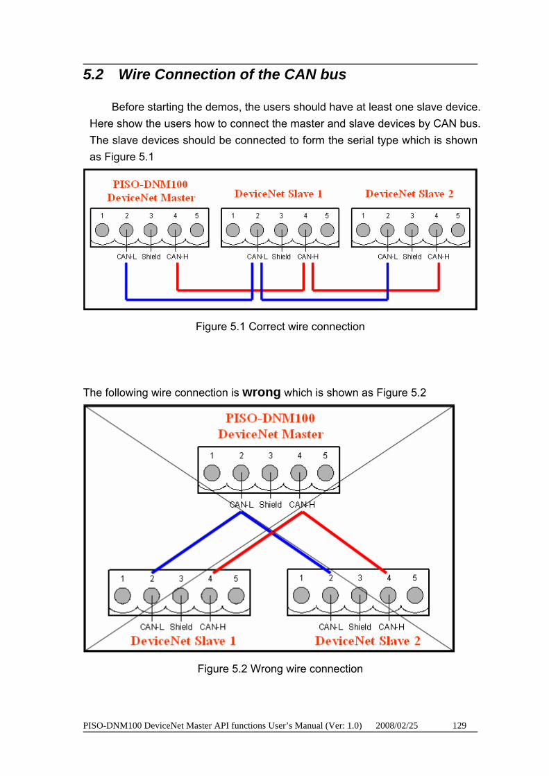
PISO-DNM100 DeviceNet Master API functions User’s Manual (Ver: 1.0) 2008/02/25 129
5.2 Wire Connection of the CAN bus
Before starting the demos, the users should have at least one slave device. Here show the users how to connect the master and slave devices by CAN bus. The slave devices should be connected to form the serial type which is shown as Figure 5.1
Figure 5.1 Correct wire connection
The following wire connection is wrong which is shown as Figure 5.2
Figure 5.2 Wrong wire connection

PISO-DNM100 DeviceNet Master API functions User’s Manual (Ver: 1.0) 2008/02/25 130
5.3 VC_Demo1 Introduction
VC_Demo1 is the example used for starting the DeviceNet communication. The screen shoot is shown as Figure 5.3. This demo program is designed to communicate with slave device step by step. This program will read the input value of the slave device when the POLL connection has been established. Before exercising this demo, the users should have at least one DeviceNet slave device which has input channels (AI or DI) and finish the wire connection between the Master and slave device. (See Figure 5.1)
Figure 5.3 the screen shoot of VC_Demo1
After running the program, the uses will see the “TotalBoard” information
on the left and up corner of the screen. This function determinates how many PISO-DNM100 in your PC automatically. If it doesn’t find any board, the users should check that the windows driver has been installed successfully. Otherwise, if it has found at lease one board, the users can continue exercising the demo program.
U
PISO-DNM100 DeviceNet Master API functions User’s Manual (Ver: 1.0) 2008/02/25 131
Step 1 : ActiveBoard Before performing other buttons, the “ActiveBoard” button should be
clicked firstly. The DIP-Switch on the board means the ID of this board. The users should make sure that every board’s ID in your PC is unique. The drop-down list will show the board’s ID which the users have selected. After clicking the button, the return code will be 0. Otherwise, please check the windows driver has been installed successfully.
UStep 2 : Clear All Config
To avoid unknown configuration in the PISO-DNM100, the users can push this button to clear all configuration in the board.
UStep 3 : Set Baud Rate
The default baud rate is 125Kbps. If the users want to change the value, you can select the correct value then push the button. After changing the baud rate, the uses should reset the firmware in PISO-DNM100 by pushing the “ResetFirmware” button. Wait for 1 or 2 seconds then go to the next step.
UStep 4 : Set Master ID
The default Master’s MAC ID is 0. If the users want to change the value, you can select the correct value then click the button. After changing the Master’s ID, the uses should reset the firmware in PISO-DNM100 by clicking the “ResetFirmware” button. Wait for 1 or 2 seconds then go to the next step.
UStep 5 : Debug Device
Before performing this function, the users should set the MAC ID of the slave device and turn on it. In the demo, the user can select the MAC ID of the slave device then click “Debug Device” button. This function will try to find the remote slave device which the user has appointed. Wait for 5 seconds, if the slave device exists in the network, the return value will be 0. Otherwise, the device doesn’t exist or has no response. The users can go to next step until the problem of the slave device has been solved.
UStep 6 : Add Device
Before performing this function, the users should use step 5 to find an exist device. This function is to add the device’s information which have be found at step 5 into EEPROM in the PISO-DNM100. If it is successful, the return value will be 0.
PISO-DNM100 DeviceNet Master API functions User’s Manual (Ver: 1.0) 2008/02/25 132
UStep 7 : Get POLL Info
This function is to obtain the device’s POLL information. After the slave device responses the data, it will show in the “In” and “Out”. “In” means the input length of the slave device. “Out” means the output length of the slave device. If the slave device responses successfully, the return value will be 0.
UStep 8 : Config POLL
If the step 7 is successful, the users can perform “Config POLL” button. This function is to add the device’s POLL information into EEPROM in PISO-DNM100. If it is successful, the return value will be 0.
UStep 9 : Start Device
If the step 8 is successful, the users can perform “Start Device” button. This function will communicate with the slave device which the users have configured in the previous steps. If it is successful, the return value will be 0.
UStep 10 : Read POLL Input I/O Data
If the master is communicating with the slave device successfully, the users can read the input I/O data from the slave device in this step. This function will obtain the input I/O data and show them in byte (8-bits). If the users have 8 digits input, the return value will show 1 byte. Similarly, if the users have 16 digits input, the return value will show 2 bytes. And so on.
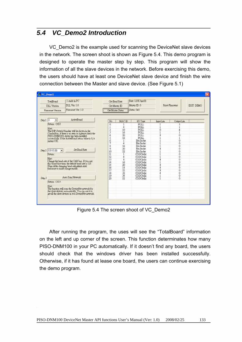
PISO-DNM100 DeviceNet Master API functions User’s Manual (Ver: 1.0) 2008/02/25 133
5.4 VC_Demo2 Introduction
VC_Demo2 is the example used for scanning the DeviceNet slave devices in the network. The screen shoot is shown as Figure 5.4. This demo program is designed to operate the master step by step. This program will show the information of all the slave devices in the network. Before exercising this demo, the users should have at least one DeviceNet slave device and finish the wire connection between the Master and slave device. (See Figure 5.1)
Figure 5.4 The screen shoot of VC_Demo2
After running the program, the uses will see the “TotalBoard” information on the left and up corner of the screen. This function determinates how many PISO-DNM100 in your PC automatically. If it doesn’t find any board, the users should check that the windows driver has been installed successfully. Otherwise, if it has found at lease one board, the users can continue exercising the demo program.
U
PISO-DNM100 DeviceNet Master API functions User’s Manual (Ver: 1.0) 2008/02/25 134
Step 1 : ActiveBoard Before performing other buttons, the “ActiveBoard” button should be
clicked firstly. The DIP-Switch on the board means the ID of this board. The users should make sure that every board’s ID in your PC is unique. The drop-down list will show the board’s ID which the users have selected. After clicking the button, the return code will be 0. Otherwise, please check the windows driver has been installed successfully.
UStep 2 : Set Baud Rate
The default baud rate is 125Kbps. If the users want to change the value, you can select the correct value then click the button. After changing the baud rate, the uses should reset the firmware in PISO-DNM100 by clicking the “ResetFirmware” button. Wait for 1 or 2 seconds then go to the next step.
UStep 3 : Auto Scan Network
Before performing this function, the users should set the MAC ID and the baud rate of the slave device and turn on it. In the demo, the user can click “Auto Scan Network” button to obtain all the I/O information of all slave devices in the network. Wait for 30 seconds. If the remote slave devices exist or have response, the users will see the entire slave device and their I/O information in the list table.
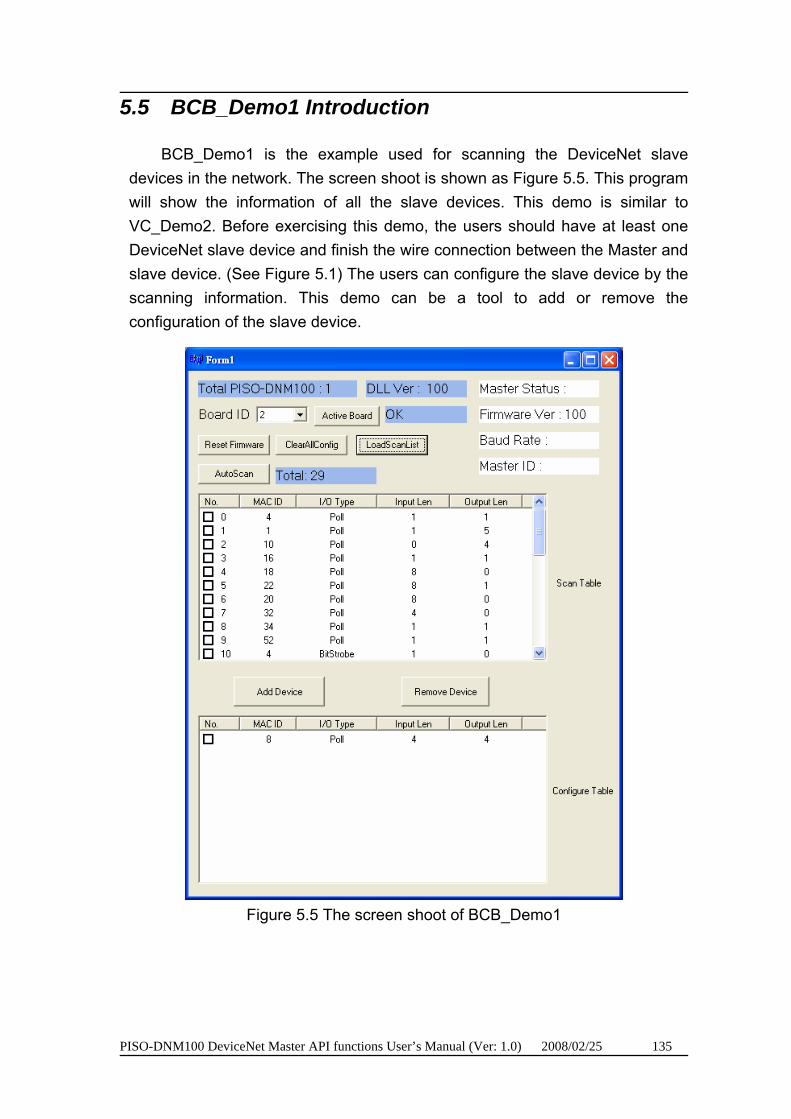
PISO-DNM100 DeviceNet Master API functions User’s Manual (Ver: 1.0) 2008/02/25 135
5.5 BCB_Demo1 Introduction
BCB_Demo1 is the example used for scanning the DeviceNet slave devices in the network. The screen shoot is shown as Figure 5.5. This program will show the information of all the slave devices. This demo is similar to VC_Demo2. Before exercising this demo, the users should have at least one DeviceNet slave device and finish the wire connection between the Master and slave device. (See Figure 5.1) The users can configure the slave device by the scanning information. This demo can be a tool to add or remove the configuration of the slave device.
Figure 5.5 The screen shoot of BCB_Demo1

PISO-DNM100 DeviceNet Master API functions User’s Manual (Ver: 1.0) 2008/02/25 136
After running the program, the users will see the “Total PISO-DNM100 : x” information on the left and up corner of the screen. This function determinates how many PISO-DNM100 in your PC automatically. If it doesn’t find any board, the users should check that the windows driver has been installed successfully. Otherwise, if it has found at lease one board, the users can continue exercising the demo program.
UStep 1 : Active Board
Before performing other button, the “Active Board” button should be clicked firstly. The DIP-Switch on the board means the ID of this board. The users should make sure that every board’s ID in your PC is unique. The drop-down list will show the board’s ID which the users have selected. After clicking the button, the return code will be 0. Otherwise, please check the windows driver has been installed successfully.
UStep 2 : Auto Scan
Before performing this function, the users should set the MAC ID and the baud rate of the slave device and turn on it. In the demo, the user can click “Auto Scan” button to obtain all the I/O information of all slave devices in the network. Wait for 30 seconds. If the remote slave devices exist or have response, the users will see the entire slave device and their I/O information in the “Scan Table”.
UStep 3 : Add Device
This function is to add the device’s information into EEPROM in the PISO-DNM100. The users can check the item which you want to add. After checking what you want, push “Add Device” button to add the information into the EEPROM. If it is successful, the items which you selected will be shown in the “Configure Table”.
UStep 4 : LoadScanList
This function is to obtain the device’s information from EEPROM in the PISO-DNM100. The users can check the information in the EEPROM. After performing the function, the information will be shown in the “Configure Table”.
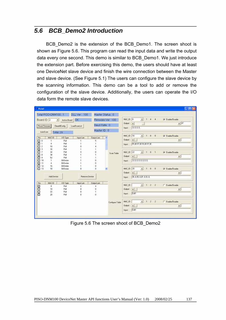
PISO-DNM100 DeviceNet Master API functions User’s Manual (Ver: 1.0) 2008/02/25 137
5.6 BCB_Demo2 Introduction
BCB_Demo2 is the extension of the BCB_Demo1. The screen shoot is shown as Figure 5.6. This program can read the input data and write the output data every one second. This demo is similar to BCB_Demo1. We just introduce the extension part. Before exercising this demo, the users should have at least one DeviceNet slave device and finish the wire connection between the Master and slave device. (See Figure 5.1) The users can configure the slave device by the scanning information. This demo can be a tool to add or remove the configuration of the slave device. Additionally, the users can operate the I/O data form the remote slave devices.
Figure 5.6 The screen shoot of BCB_Demo2
PISO-DNM100 DeviceNet Master API functions User’s Manual (Ver: 1.0) 2008/02/25 138
If the users want to know how to configure the slave device information into EEPROM in the PISO-DNM100, please refer to section 5.5.
If “Active Board” is OK, the users can click “LoadScanList” button. The configuration information will be shown in “Configure Table”. At the same time, the MAC IDs also are shown on the right side of the screen. The users can check the “Enable/Disable” box to enable or disable the read and write the I/O data. The “Output” scroll bar presents the output value which will be written to the output channel of the slave device. If the scroll value is 0x23, every byte of the slave device’s output is 0x23. The users can find out the change of the output channel easily. The “Input” field presents the input value which has been read from the input channel of the slave device.