Piping Queries
4
1. Thermal Expansion of Pipe Thermal expansion is the tendency of matter to change in volume in response to a change in temperature. L = L 0 α (t 1 - t 0 ) Where. L = change in length (m) L 0 = initial length (m) α = linear expansion coefficient (m/m ° C) The coefficient of linear expansion of solid is defined as the increment of length in a unit length for a change in temperature of one degree. t 0 = initial temperature ( ° C) t 1 = final temperature ( ° C) 2. Pipe Bending factor 3. Torsional Load on Pipe Torsion is the twisting of an object due to an applied torque, therefore is expressed in N·m 4. Co-efficient of friction in Pipe Where, P = Pressure loss in terms of head, mm of fluid column f = Coefficient of friction V = Velocity of fluid, m/ se c. L = Total length of pipe, m g = Acceleration due to gravity = 9.80665 m/sec 2 d = Average inside diameter of pipe, m f = {Re : e/d} Fraction factor have to find from Moody diagram. Re – Reynolds Number which is used to find out the type flow. e/d – Relative Roughness e – Surface roughness of the pipe (Steel Pipe = 0.003, Cast Iron = 0.01) d – Diameter of pipe Reynolds Number - A dimensionless number. It is defined as the ratio of the dynamic forces of mass flow to the shear stress due to viscosity. It is expressed as Where R - Reynolds number - mean velocity of flow, m/s
-
Upload
siva242245 -
Category
Documents
-
view
218 -
download
0
Transcript of Piping Queries
8/12/2019 Piping Queries
http://slidepdf.com/reader/full/piping-queries 1/4
1. Thermal Expansion of Pipe
Thermal expansion is the tendency of matter to change in volume in response to a change in
temperature.
L = L0 α (t1 - t0)
Where.
L = change in length (m)
L0 = initial length (m)
α = linear expansion coefficient (m/m°C)
The coefficient of linear expansion of solid is defined as the increment of length in a unit length for
a change in temperature of one degree.
t0 = initial temperature (°C)
t1 = final temperature (°C)
2. Pipe Bending factor
3. Torsional Load on Pipe
Torsion is the twisting of an object due to an applied torque, therefore is expressed in N·m
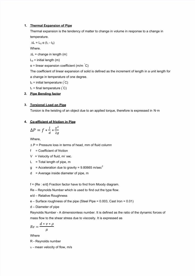
4. Co-efficient of friction in Pipe
Where,
P = Pressure loss in terms of head, mm of fluid column
f = Coefficient of friction
V = Velocity of fluid, m/ sec.
L = Total length of pipe, m
g = Acceleration due to gravity = 9.80665 m/sec2
d = Average inside diameter of pipe, m
f = {Re : e/d} Fraction factor have to find from Moody diagram.
Re – Reynolds Number which is used to find out the type flow.
e/d – Relative Roughness
e – Surface roughness of the pipe (Steel Pipe = 0.003, Cast Iron = 0.01)
d – Diameter of pipe
Reynolds Number - A dimensionless number. It is defined as the ratio of the dynamic forces of
mass flow to the shear stress due to viscosity. It is expressed as
Where
R - Reynolds number - mean velocity of flow, m/s

8/12/2019 Piping Queries
http://slidepdf.com/reader/full/piping-queries 2/4
- Weight density of fluid, kg/m3
D - Internal diameter of pipe, m
- Absolute viscosity, N s/m2
Laminar flow
The Darcy friction factor for laminar flow (Reynolds number less than 2000) is given by the
following formula:
where:
is the Darcy friction factor
is the Reynolds number.
Re ≤ 2300 (Laminar Flow)Re = 2300 – 4000 (Transition Flow)
Re > 4000 (Turbulent Flow)
5. Specific Gravity of Pipe
The specific gravity of a solid or liquid is the ratio of the mass of an equal volume of water at
standard temperature.
6. Piping Operation Life
Desired life cycle for Piping in operation is 20 Years (7000 Cycles).
7. Stress Intensity Factor in pipe
Stress Intensity Factor (SIF) is the ratio of maximum stress intensity to normal stress. It is used as
safe factor to account for the effect of localised stress on piping under respective loading. In
piping it is applied to welds, f ittings, branch connections etc… where stress concentration and
possible fatigue failure may occur.
8. Calculation of Pipe Spacing
9. Heat Exchanger
a) Cleaner Fluid
b) Corrosive Fluid
Shell and tube type is the most popular arrangement. A number of small bore pipes are fitted
between two tube plates and one fluid flows through these tubes. The tube bundle is placed
inside a shell and the other fluid flows through the shell and over the surface of the tubes.
Compact arrangement is possible with this type. The sub types of shell and tube arrangement are
one shell pass and 2, 4 or multiple tube passes.

8/12/2019 Piping Queries
http://slidepdf.com/reader/full/piping-queries 3/4
c) Shell Side
The shell is a container for the shell fluid. Usually, it is cylindrical in shape with a circular cross
section, although shells of different shapes are used in specific applications and in nuclear heat
exchangers to conform to the tube bundle shape.
d) Tube SideRound tubes in various shapes are used in shell-and-tube exchangers. Most common are the
tube bundles with straight and U-tubes used in process and power industry exchangers.
10. Water Hammer Effect
Water hammer (or, more generally, fluid hammer) is a pressure surge or wave resulting when a
fluid (usually a liquid but sometimes also a gas) in motion is forced to stop or change direction
suddenly (momentum change). Water hammer commonly occurs when a valve is closed suddenly
at an end of a pipeline system, and a pressure wave propagates in the pipe. It may also be known
as hydraulic shock.
11. Drip Leg in Steam Line
Drip legs must be located and designed to remove condensate from steam lines throughout the
operation cycle, regardless of condensate flow conditions.
Drip legs must be large enough to allow condensate to drop out of the steam at the pipe bottom.
8/12/2019 Piping Queries
http://slidepdf.com/reader/full/piping-queries 4/4
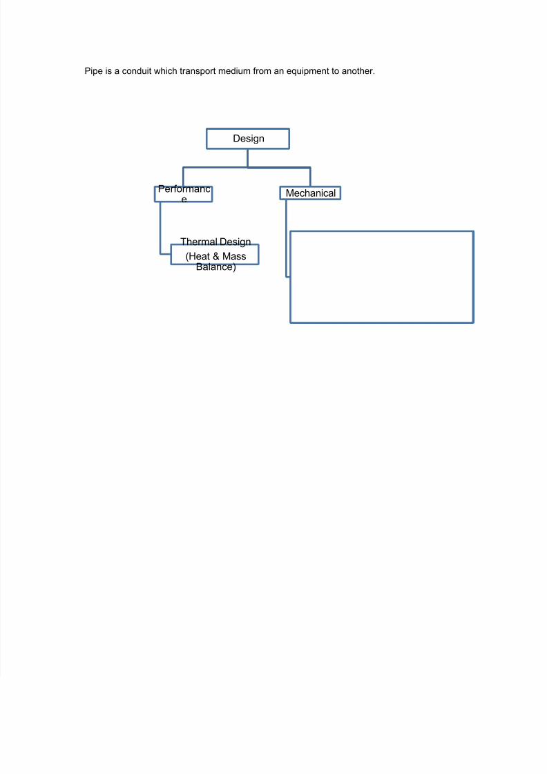
Pipe is a conduit which transport medium from an equipment to another.
Design
Performance
Thermal Design
(Heat & Mass
Balance)
Mechanical