PIPES, FITTINGS AND MANUAL VALVES - fipnet.com · PIPES, FITTINGS AND MANUAL VALVES PVc-c PIPES,...
216
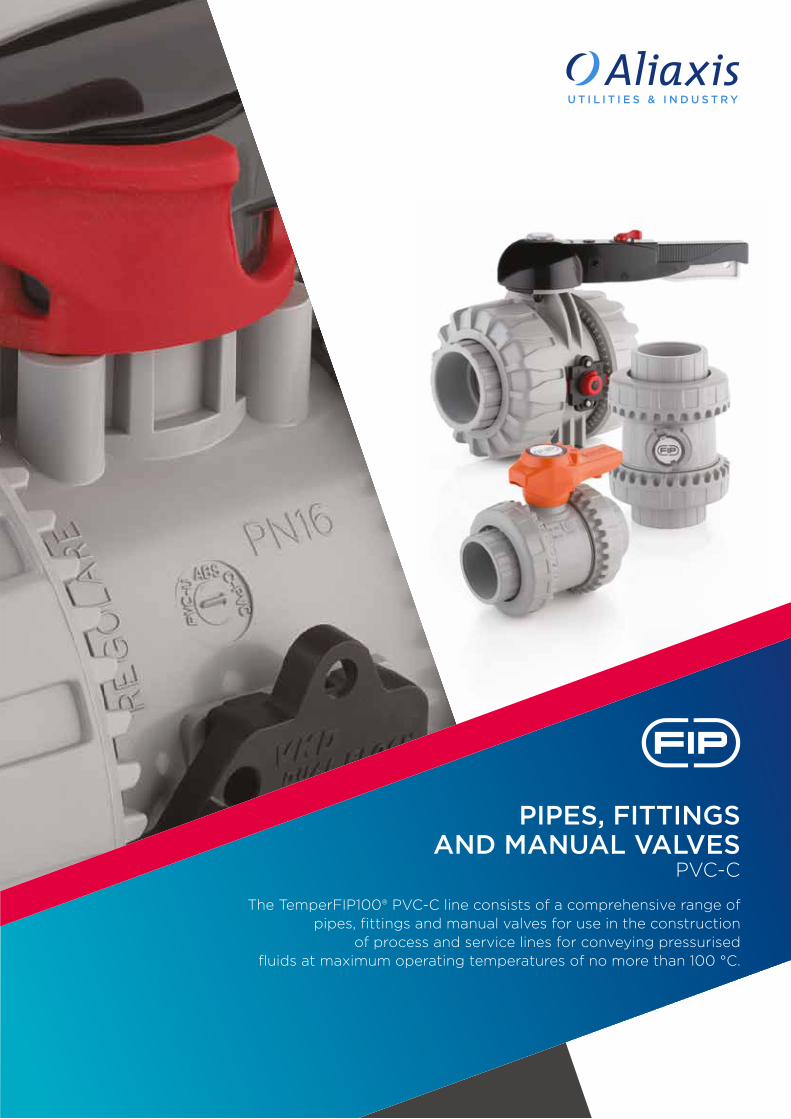
PIPES, FITTINGS AND MANUAL VALVES PVC-C The TemperFIP100® PVC-C line consists of a comprehensive range of pipes, fittings and manual valves for use in the construction of process and service lines for conveying pressurised fluids at maximum operating temperatures of no more than 100 °C.
Transcript of PIPES, FITTINGS AND MANUAL VALVES - fipnet.com · PIPES, FITTINGS AND MANUAL VALVES PVc-c PIPES,...
PIP
ES,
FIT
TIN
GS
AN
D M
AN
UA
L VA
LVE
SPV
c-c
PIPES, FITTINGS AND MANUAL VALVES
PVc-c
The TemperFIP100® PVc-c line consists of a comprehensive range ofpipes, fittings and manual valves for use in the construction
of process and service lines for conveying pressurised fluids at maximum operating temperatures of no more than 100 °c.
PVC-CGeneral characteristicsReference standardsApprovals and quality marksMain propertiesSolvent welding instructions
page 2page 4page 6page 8page 9
ISO-UNI pipeTemperFIP100® pressure pipe page 16
ISO-UNI fittingsTemperFIP100® solvent weld fittings, metric series page 24
ISO-BSP fittingsTemperFIP100® adaptor fittings page 40
VKD DN 10÷50DUAL BLOCK® 2-way ball valve page 54
VKD DN 65÷100DUAL BLOCK® 2-way ball valve page 70
TKD DN 10÷50DUAL BLOCK® 3-way ball valve page 84
VXE DN 10÷50Easyfit 2-way ball valve page 100
VXE DN 65÷100Easyfit 2-way ball valve page 112
SXE DN 10÷50Easyfit True Union ball check valve page 126
SXE DN 65÷100Easyfit True Union ball check valve page 138
FK DN 40÷300Butterfly valve page 150
DK DN 15÷65DIALOCK® 2-way diaphragm valve page 170
VM DN 80÷100Diaphragm valve page 186
CM DN 12÷15Compact diaphragm valve page 196
RV DN 15÷50Sediment strainer page 204
Key abbreviations page 213
PIPE, FITTINGS AND MANUAL
VALVES IN PVC-C
CONTENTS
PVC-C
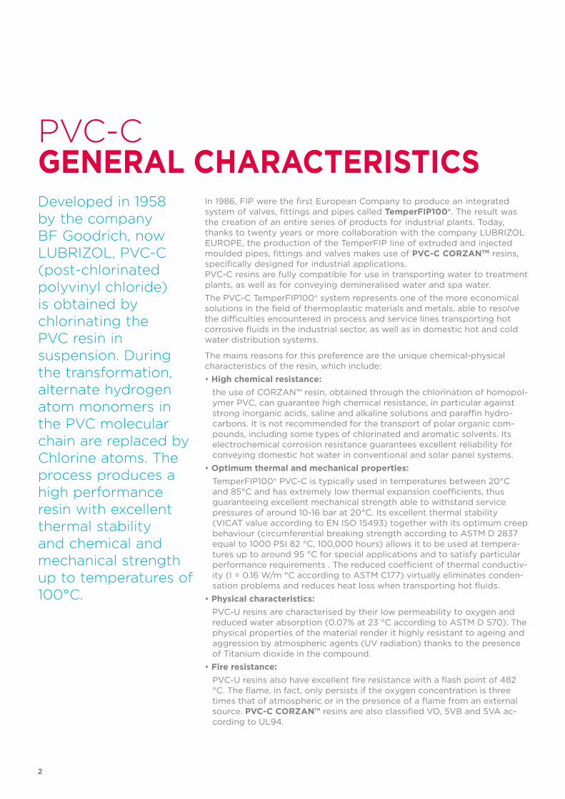
Developed in 1958 by the company BF Goodrich, now LUBRIZOL, PVC-C (post-chlorinated polyvinyl chloride) is obtained by chlorinating the PVC resin in suspension. During the transformation, alternate hydrogen atom monomers in the PVC molecular chain are replaced by Chlorine atoms. The process produces a high performance resin with excellent thermal stability and chemical and mechanical strength up to temperatures of 100°C.
In 1986, FIP were the first European Company to produce an integrated system of valves, fittings and pipes called TemperFIP100®. The result was the creation of an entire series of products for industrial plants. Today, thanks to twenty years or more collaboration with the company LUBRIZOL EUROPE, the production of the TemperFIP line of extruded and injected moulded pipes, fittings and valves makes use of PVC-C CORZANTM resins, specifically designed for industrial applications. PVC-C resins are fully compatible for use in transporting water to treatment plants, as well as for conveying demineralised water and spa water.The PVC-C TemperFIP100® system represents one of the more economical solutions in the field of thermoplastic materials and metals, able to resolve the difficulties encountered in process and service lines transporting hot corrosive fluids in the industrial sector, as well as in domestic hot and cold water distribution systems.
The mains reasons for this preference are the unique chemical-physical characteristics of the resin, which include:• High chemical resistance: the use of CORZAN™ resin, obtained through the chlorination of homopol-
ymer PVC, can guarantee high chemical resistance, in particular against strong inorganic acids, saline and alkaline solutions and paraffin hydro-carbons. It is not recommended for the transport of polar organic com-pounds, including some types of chlorinated and aromatic solvents. Its electrochemical corrosion resistance guarantees excellent reliability for conveying domestic hot water in conventional and solar panel systems.
• Optimum thermal and mechanical properties: TemperFIP100® PVC-C is typically used in temperatures between 20°C
and 85°C and has extremely low thermal expansion coefficients, thus guaranteeing excellent mechanical strength able to withstand service pressures of around 10-16 bar at 20°C. Its excellent thermal stability (VICAT value according to EN ISO 15493) together with its optimum creep behaviour (circumferential breaking strength according to ASTM D 2837 equal to 1000 PSI 82 °C, 100,000 hours) allows it to be used at tempera-tures up to around 95 °C for special applications and to satisfy particular performance requirements . The reduced coefficient of thermal conductiv-ity (I = 0.16 W/m °C according to ASTM C177) virtually eliminates conden-sation problems and reduces heat loss when transporting hot fluids.
• Physical characteristics: PVC-U resins are characterised by their low permeability to oxygen and
reduced water absorption (0.07% at 23 °C according to ASTM D 570). The physical properties of the material render it highly resistant to ageing and aggression by atmospheric agents (UV radiation) thanks to the presence of Titanium dioxide in the compound.
• Fire resistance: PVC-U resins also have excellent fire resistance with a flash point of 482
°C. The flame, in fact, only persists if the oxygen concentration is three times that of atmospheric or in the presence of a flame from an external source. PVC-C CORZAN™ resins are also classified VO, 5VB and 5VA ac-cording to UL94.
GENERAL CHARACTERISTICS
2
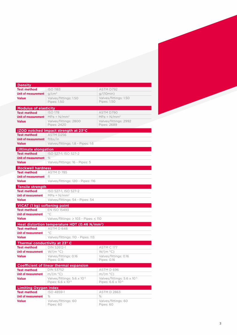
DensityTest method ISO 1183 ASTM D792Unit of measurement g/cm3 g/(10min)Value Valves/fittings: 1.50
Pipes: 1.50Valves/fittings: 1.50Pipes: 1.50
Modulus of elasticityTest method ISO 178 ASTM D790Unit of measurement MPa = N/mm2 MPa = N/mm2
Value Valves/fittings: 2800Pipes: 2420
Valves/fittings: 2992Pipes: 2689
IZOD notched impact strength at 23°CTest method ASTM D256Unit of measurement ftlbs/inValue Valves/fittings: 1.8 - Pipes: 1.6
Ultimate elongationTest method ISO 527-1, ISO 527-2 Unit of measurement %Value Valves/fittings: 16 - Pipes: 5
Rockwell hardnessTest method ASTM D 785Unit of measurement RValue Valves/fittings: 120 - Pipes: 116
Tensile strengthTest method ISO 527-1, ISO 527-2Unit of measurement MPa = N/mm2
Value Valves/fittings: 54 - Pipes: 54
VICAT (1 kg) softening pointTest method EN ISO 15493 Unit of measurement °CValue Valves/fittings: > 103 - Pipes: < 110
Heat distortion temperature HDT (0.46 N/mm2)Test method ASTM D 648 Unit of measurement °CValue Valves/fittings: 110 - Pipes: 113
Thermal conductivity at 23° CTest method DIN 52612-1 ASTM C 177Unit of measurement W/(m °C) W/(m °C)Value Valves/fittings: 0.16
Pipes: 0.16Valves/fittings: 0.16Pipes: 0.16
Coefficient of linear thermal expansionTest method DIN 53752 ASTM D 696Unit of measurement m/(m °C) m/(m °C)Value Valves/fittings: 5.6 x 10⁻⁵
Pipes: 6.6 x 10⁻⁵Valves/fittings: 5.6 x 10⁻⁵ Pipes: 6.6 x 10⁻⁵
Limiting Oxygen IndexTest method ISO 4859-1 ASTM D 2863Unit of measurement % %Value Valves/fittings: 60
Pipes: 60Valves/fittings: 60Pipes: 60
3
REFERENCE
• ANSI B16.5 Pipe flanges and stubs-NPS 1/2 to NPS 24 mm/inch.• ASTM D1784 cl. 23548B Rigid PVC and PVC-C compounds (for industrial applications).• ASTM F437 PVC-C threaded pipe fittings, sch. 80.• ASTM F439 PVC-C pipe fittings.• ASTM F441 PVC-C pipe, sch. 40 and 80.• BS 10 Specification for flanges and bolts for pipes, valves and fittings.• BS 1560 Flanges for pipes, valves and fittings (Class designated). Steel, cast iron
and copper alloy flanges. Specification for steel flanges. • BS 4504 Flanges for pipes, valves and fittings (PN designated).• DIN 2501 Flanges, dimensions.• DIN 2999 Threads for pipes and fittings.• DIN 8063 Dimensions of PVC-C fittings.• DIN 8079-8080 PVC-C pipes, dimensions.• DIN 16962 PVC-C fittings for butt-welding or socket fusion, dimensions.• DIN 16963 Pipe connections and pipe components for pressurised fluids in HDPE.• EN 558-1 Industrial valves - face-to-face and centre-to-face dimensions of metal
valves for use in flanged pipe systems - Part 1: PN designated valves.• EN 1092-1 Flanges and their joints - Circular flanges for pipes, valves and accessories
- Part 1: Steel flanges, PN designated.• EN ISO 15493 Specifications for components and the system (Pipes, Fittings and Valves)
in PVC-C for industrial applications.• ISO 228-1 PVC-C fittings with threaded connections.• ISO 5211 Industrial valves - Part-turn actuator couplings
STANDARDSProduction of the TemperFIP100® PVC-C lines is carried out according to the highest quality standards and in full compliance with the environmental restrictions set by the applicable laws in force and in accordance with standard ISO 14001.All products are manufactured in accordance with a quality assurance system complying with standard ISO 9001.

• ISO 7005-1 Pipe flanges - Part 1: Steel flanges. • JIS B 2220 Steel pipe flanges.• UNI 11242 Solvent welding of PVC-C pipes, fittings and valves
5
APPROVALS AND
• ABS The TemperFIP100® PVC-C system is recognised as suitable for convey-
ing and treating sanitary and conditioning water onboard ships and other units classified by the American Bureau of Shipping (ABS).
• ACS The TemperFIP100® PVC-C system is certified as suitable for coming into
contact with water intended for human consumption according to the At-testation de conformité sanitaire (ACS).
• Bureau Veritas The TemperFIP100® PVC-C system is recognised as suitable for convey-
ing and treating sanitary and conditioning water onboard ships and other units classified by the Bureau Veritas - Marine Division.
• DIBt TemperFIP100® PVC-C valves have been tested and certified by DIBt
(Deutsche Institut für Bautechnik)
• DNV The TemperFIP100® PVC-C system is recognised as suitable for convey-
ing and treating sanitary and conditioning water onboard ships and other units classified by DNV.
• GOST-R - EAC The TemperFIP100® PVC-C system is GOST-R and EAC certified in accord-
ance with Russian regulations on Safety, Hygiene and Quality
• Lloyd’s Register The TemperFIP100® PVC-C pipes and fittings are recognised as suitable for
conveying and treating sanitary and conditioning water onboard ships and other units classified by Lloyd’s Register.
QUALITY MARKS
6
• NSF (National Sanitation Foundation USA) FIP PVC-C ball valves are listed according to the NSF/ANSI Standard 61 -
Drinking Water System Components - Health Effects.
• TA-Luft TemperFIP100® PVC-C valves have been tested and certified according to
“TA-Luft” by MPA Stuttgart in compliance with the Technical Instruction on Air Quality Control TA-Luft/ VDI 2440.
• UKR SEPRO TemperFIP100® PVC-C valves and fittings are certified in accordance with
Ukrainian regulations on Safety, Hygiene and Quality.
• WRAS TemperFIP100® PVC-C valves are recognised by the WRAS (Water Regula-
tion Advisory Scheme - UK)
7
MAINPROPERTIES
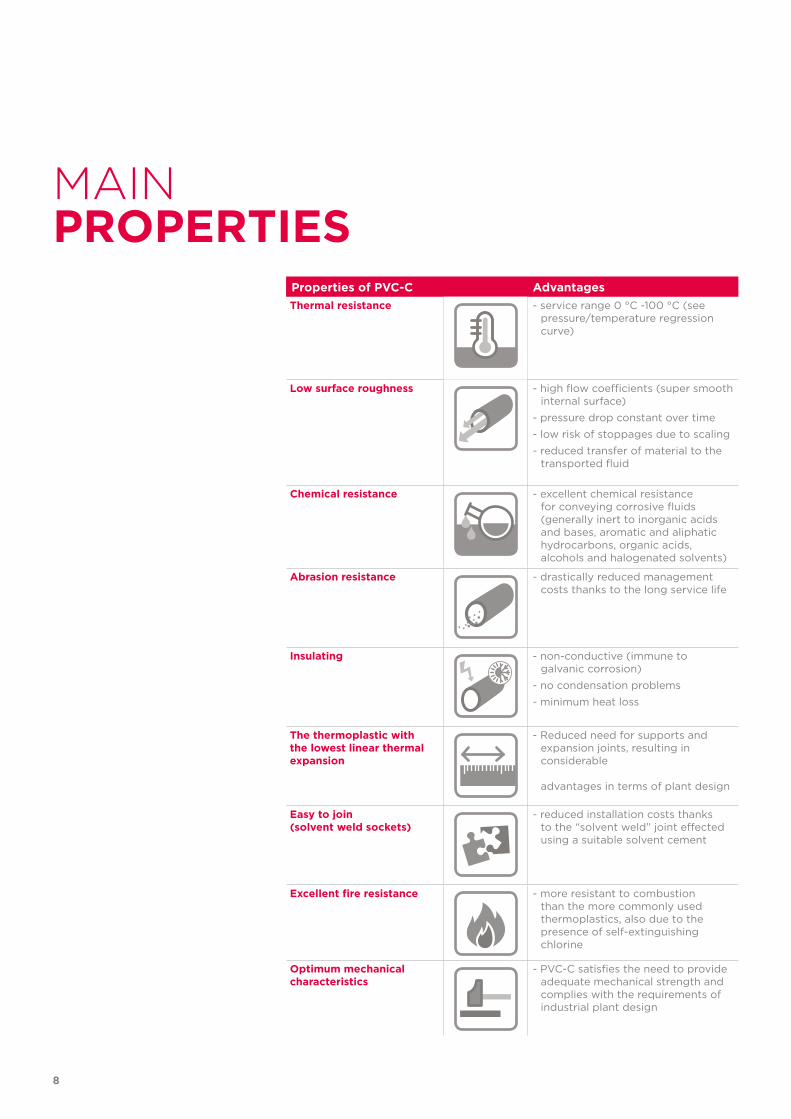
Properties of PVC-C AdvantagesThermal resistance - service range 0 °C -100 °C (see
pressure/temperature regression curve)
Low surface roughness - high flow coefficients (super smooth internal surface)
- pressure drop constant over time
- low risk of stoppages due to scaling
- reduced transfer of material to the transported fluid
Chemical resistance - excellent chemical resistance for conveying corrosive fluids (generally inert to inorganic acids and bases, aromatic and aliphatic hydrocarbons, organic acids, alcohols and halogenated solvents)
Abrasion resistance - drastically reduced management costs thanks to the long service life
Insulating - non-conductive (immune to galvanic corrosion)
- no condensation problems
- minimum heat loss
The thermoplastic with the lowest linear thermal expansion
- Reduced need for supports and expansion joints, resulting in considerable advantages in terms of plant design
Easy to join (solvent weld sockets)
- reduced installation costs thanks to the “solvent weld” joint effected using a suitable solvent cement
Excellent fire resistance - more resistant to combustion than the more commonly used thermoplastics, also due to the presence of self-extinguishing chlorine
Optimum mechanical characteristics
- PVC-C satisfies the need to provide adequate mechanical strength and complies with the requirements of industrial plant design
8
SOLVENT WELDINGINSTRUCTIONS
Fig. 2
Fig. 1
Fig. 3 Fig. 4 Fig. 5
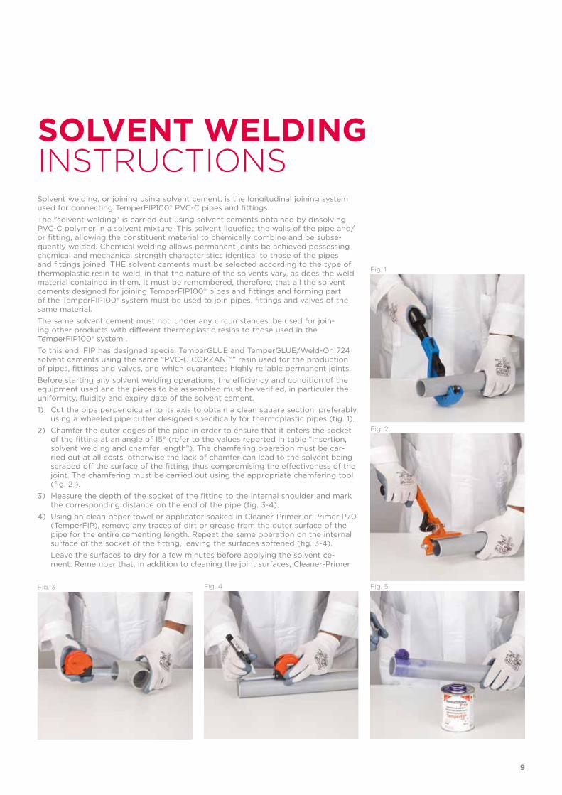
Solvent welding, or joining using solvent cement, is the longitudinal joining system used for connecting TemperFIP100® PVC-C pipes and fittings.The "solvent welding" is carried out using solvent cements obtained by dissolving PVC-C polymer in a solvent mixture. This solvent liquefies the walls of the pipe and/or fitting, allowing the constituent material to chemically combine and be subse-quently welded. Chemical welding allows permanent joints be achieved possessing chemical and mechanical strength characteristics identical to those of the pipes and fittings joined. THE solvent cements must be selected according to the type of thermoplastic resin to weld, in that the nature of the solvents vary, as does the weld material contained in them. It must be remembered, therefore, that all the solvent cements designed for joining TemperFIP100® pipes and fittings and forming part of the TemperFIP100® system must be used to join pipes, fittings and valves of the same material.The same solvent cement must not, under any circumstances, be used for join-ing other products with different thermoplastic resins to those used in the TemperFIP100® system .To this end, FIP has designed special TemperGLUE and TemperGLUE/Weld-On 724 solvent cements using the same “PVC-C CORZANTM” resin used for the production of pipes, fittings and valves, and which guarantees highly reliable permanent joints.Before starting any solvent welding operations, the efficiency and condition of the equipment used and the pieces to be assembled must be verified, in particular the uniformity, fluidity and expiry date of the solvent cement.1) Cut the pipe perpendicular to its axis to obtain a clean square section, preferably
using a wheeled pipe cutter designed specifically for thermoplastic pipes (fig. 1).2) Chamfer the outer edges of the pipe in order to ensure that it enters the socket
of the fitting at an angle of 15° (refer to the values reported in table “Insertion, solvent welding and chamfer length”). The chamfering operation must be car-ried out at all costs, otherwise the lack of chamfer can lead to the solvent being scraped off the surface of the fitting, thus compromising the effectiveness of the joint. The chamfering must be carried out using the appropriate chamfering tool (fig. 2 ).
3) Measure the depth of the socket of the fitting to the internal shoulder and mark the corresponding distance on the end of the pipe (fig. 3-4).
4) Using an clean paper towel or applicator soaked in Cleaner-Primer or Primer P70 (TemperFIP), remove any traces of dirt or grease from the outer surface of the pipe for the entire cementing length. Repeat the same operation on the internal surface of the socket of the fitting, leaving the surfaces softened (fig. 3-4).
Leave the surfaces to dry for a few minutes before applying the solvent ce-ment. Remember that, in addition to cleaning the joint surfaces, Cleaner-Primer
9
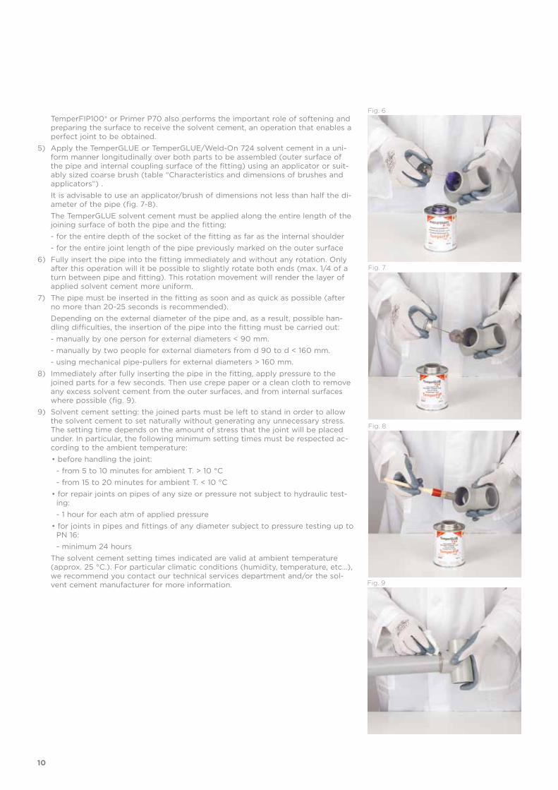
TemperFIP100® or Primer P70 also performs the important role of softening and preparing the surface to receive the solvent cement, an operation that enables a perfect joint to be obtained.
5) Apply the TemperGLUE or TemperGLUE/Weld-On 724 solvent cement in a uni-form manner longitudinally over both parts to be assembled (outer surface of the pipe and internal coupling surface of the fitting) using an applicator or suit-ably sized coarse brush (table “Characteristics and dimensions of brushes and applicators”) .
It is advisable to use an applicator/brush of dimensions not less than half the di-ameter of the pipe (fig. 7-8).
The TemperGLUE solvent cement must be applied along the entire length of the joining surface of both the pipe and the fitting:
- for the entire depth of the socket of the fitting as far as the internal shoulder - for the entire joint length of the pipe previously marked on the outer surface6) Fully insert the pipe into the fitting immediately and without any rotation. Only
after this operation will it be possible to slightly rotate both ends (max. 1/4 of a turn between pipe and fitting). This rotation movement will render the layer of applied solvent cement more uniform.
7) The pipe must be inserted in the fitting as soon and as quick as possible (after no more than 20-25 seconds is recommended).
Depending on the external diameter of the pipe and, as a result, possible han-dling difficulties, the insertion of the pipe into the fitting must be carried out:
- manually by one person for external diameters < 90 mm. - manually by two people for external diameters from d 90 to d < 160 mm. - using mechanical pipe-pullers for external diameters > 160 mm.8) Immediately after fully inserting the pipe in the fitting, apply pressure to the
joined parts for a few seconds. Then use crepe paper or a clean cloth to remove any excess solvent cement from the outer surfaces, and from internal surfaces where possible (fig. 9).
9) Solvent cement setting: the joined parts must be left to stand in order to allow the solvent cement to set naturally without generating any unnecessary stress. The setting time depends on the amount of stress that the joint will be placed under. In particular, the following minimum setting times must be respected ac-cording to the ambient temperature:• before handling the joint: - from 5 to 10 minutes for ambient T. > 10 °C - from 15 to 20 minutes for ambient T. < 10 °C• for repair joints on pipes of any size or pressure not subject to hydraulic test-
ing: - 1 hour for each atm of applied pressure• for joints in pipes and fittings of any diameter subject to pressure testing up to
PN 16: - minimum 24 hours
The solvent cement setting times indicated are valid at ambient temperature (approx. 25 °C.). For particular climatic conditions (humidity, temperature, etc…), we recommend you contact our technical services department and/or the sol-vent cement manufacturer for more information.
Fig. 8
Fig. 7
Fig. 9
Fig. 6
10
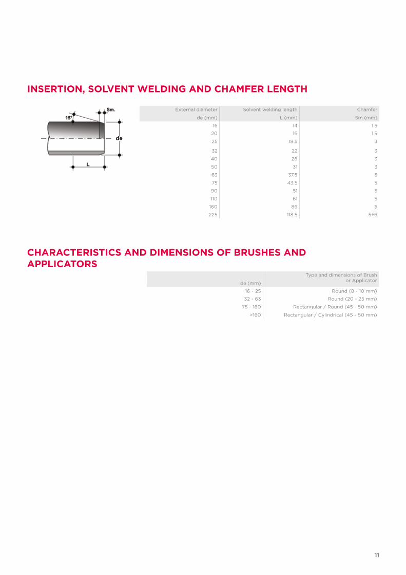
External diameter
de (mm)
Solvent welding length
L (mm)
Chamfer
Sm (mm)
16 14 1.5
20 16 1.5
25 18.5 3
32 22 3
40 26 3
50 31 3
63 37.5 5
75 43.5 5
90 51 5
110 61 5
160 86 5
225 118.5 5÷6
de (mm)
Type and dimensions of Brush or Applicator
16 - 25 Round (8 - 10 mm)
32 - 63 Round (20 - 25 mm)
75 - 160 Rectangular / Round (45 - 50 mm)
>160 Rectangular / Cylindrical (45 - 50 mm)
INSERTION, SOLVENT WELDING AND CHAMFER LENGTH
CHARACTERISTICS AND DIMENSIONS OF BRUSHES AND APPLICATORS
11
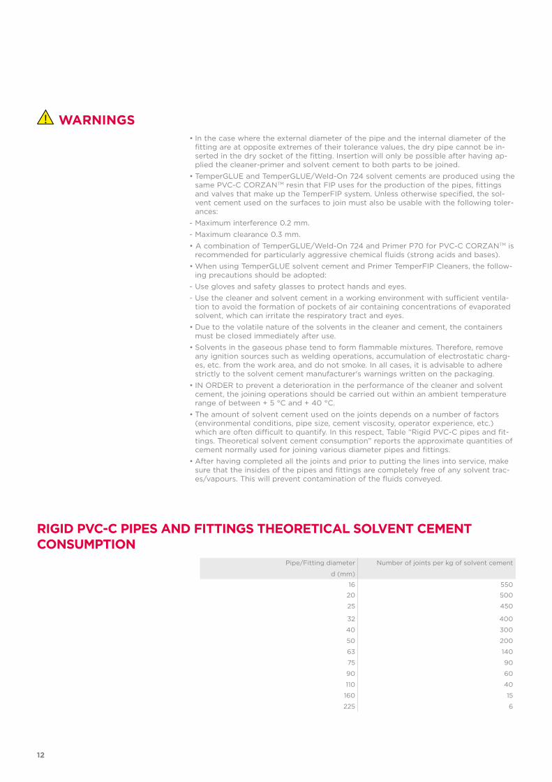
• In the case where the external diameter of the pipe and the internal diameter of the fitting are at opposite extremes of their tolerance values, the dry pipe cannot be in-serted in the dry socket of the fitting. Insertion will only be possible after having ap-plied the cleaner-primer and solvent cement to both parts to be joined.
• TemperGLUE and TemperGLUE/Weld-On 724 solvent cements are produced using the same PVC-C CORZANTM resin that FIP uses for the production of the pipes, fittings and valves that make up the TemperFIP system. Unless otherwise specified, the sol-vent cement used on the surfaces to join must also be usable with the following toler-ances:
- Maximum interference 0.2 mm.- Maximum clearance 0.3 mm. • A combination of TemperGLUE/Weld-On 724 and Primer P70 for PVC-C CORZANTM is
recommended for particularly aggressive chemical fluids (strong acids and bases).• When using TemperGLUE solvent cement and Primer TemperFIP Cleaners, the follow-
ing precautions should be adopted:- Use gloves and safety glasses to protect hands and eyes.- Use the cleaner and solvent cement in a working environment with sufficient ventila-
tion to avoid the formation of pockets of air containing concentrations of evaporated solvent, which can irritate the respiratory tract and eyes.
• Due to the volatile nature of the solvents in the cleaner and cement, the containers must be closed immediately after use.
• Solvents in the gaseous phase tend to form flammable mixtures. Therefore, remove any ignition sources such as welding operations, accumulation of electrostatic charg-es, etc. from the work area, and do not smoke. In all cases, it is advisable to adhere strictly to the solvent cement manufacturer's warnings written on the packaging.
• IN ORDER to prevent a deterioration in the performance of the cleaner and solvent cement, the joining operations should be carried out within an ambient temperature range of between + 5 °C and + 40 °C.
• The amount of solvent cement used on the joints depends on a number of factors (environmental conditions, pipe size, cement viscosity, operator experience, etc.) which are often difficult to quantify. In this respect, Table “Rigid PVC-C pipes and fit-tings. Theoretical solvent cement consumption” reports the approximate quantities of cement normally used for joining various diameter pipes and fittings.
• After having completed all the joints and prior to putting the lines into service, make sure that the insides of the pipes and fittings are completely free of any solvent trac-es/vapours. This will prevent contamination of the fluids conveyed.
WARNINGS
RIGID PVC-C PIPES AND FITTINGS THEORETICAL SOLVENT CEMENT CONSUMPTION
Pipe/Fitting diameter
d (mm)
Number of joints per kg of solvent cement
16 550
20 500
25 450
32 400
40 300
50 200
63 140
75 90
90 60
110 40
160 15
225 6
12
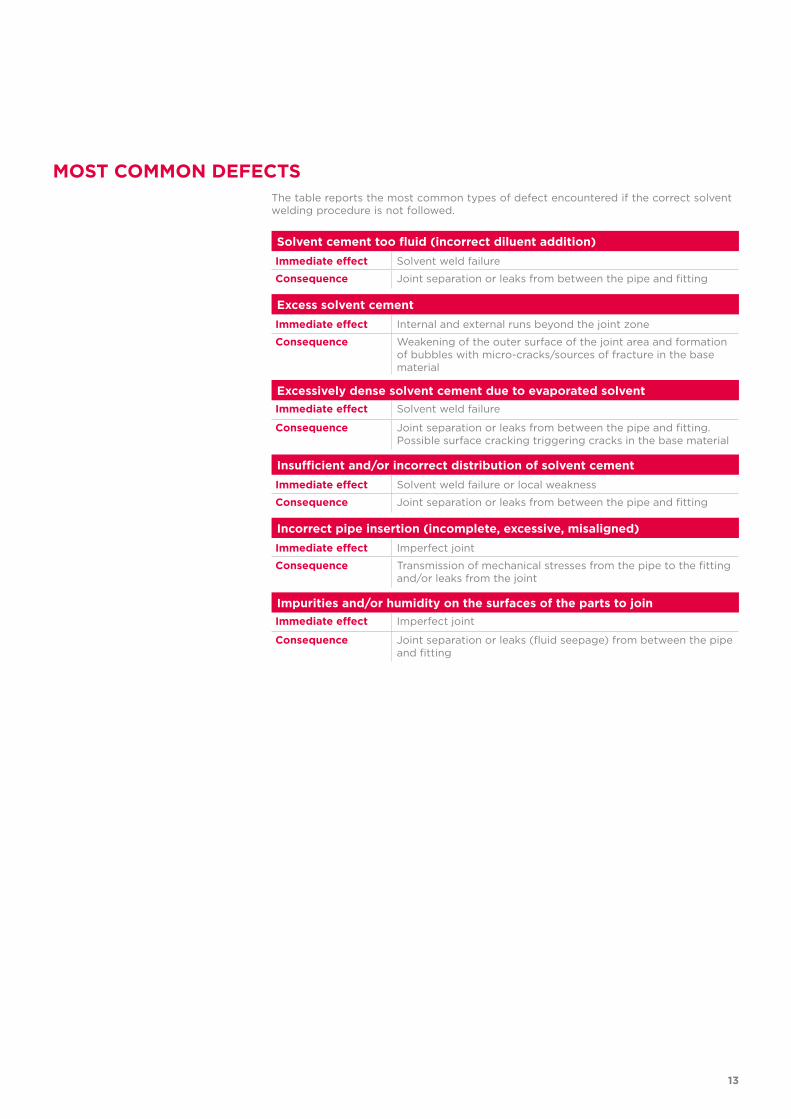
The table reports the most common types of defect encountered if the correct solvent welding procedure is not followed.
MOST COMMON DEFECTS
Solvent cement too fluid (incorrect diluent addition)Immediate effect Solvent weld failure
Consequence Joint separation or leaks from between the pipe and fitting
Excess solvent cementImmediate effect Internal and external runs beyond the joint zone
Consequence Weakening of the outer surface of the joint area and formation of bubbles with micro-cracks/sources of fracture in the base material
Excessively dense solvent cement due to evaporated solventImmediate effect Solvent weld failure
Consequence Joint separation or leaks from between the pipe and fitting.Possible surface cracking triggering cracks in the base material
Insufficient and/or incorrect distribution of solvent cementImmediate effect Solvent weld failure or local weakness
Consequence Joint separation or leaks from between the pipe and fitting
Incorrect pipe insertion (incomplete, excessive, misaligned)Immediate effect Imperfect joint
Consequence Transmission of mechanical stresses from the pipe to the fitting and/or leaks from the joint
Impurities and/or humidity on the surfaces of the parts to joinImmediate effect Imperfect joint
Consequence Joint separation or leaks (fluid seepage) from between the pipe and fitting
13

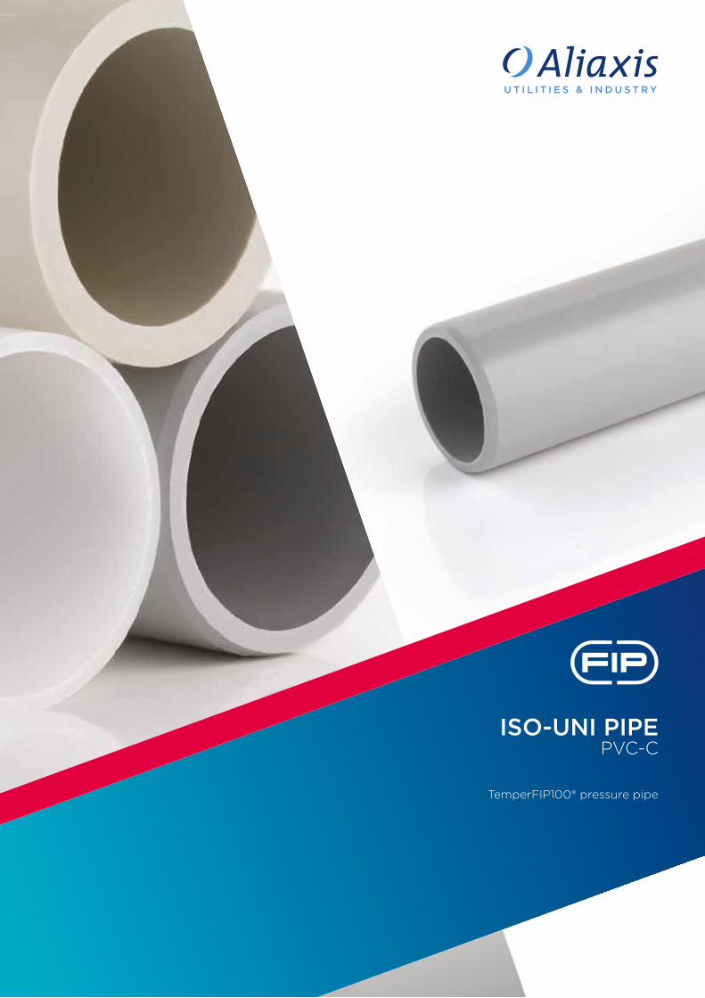
ISO-UNI PIPEPVC-C
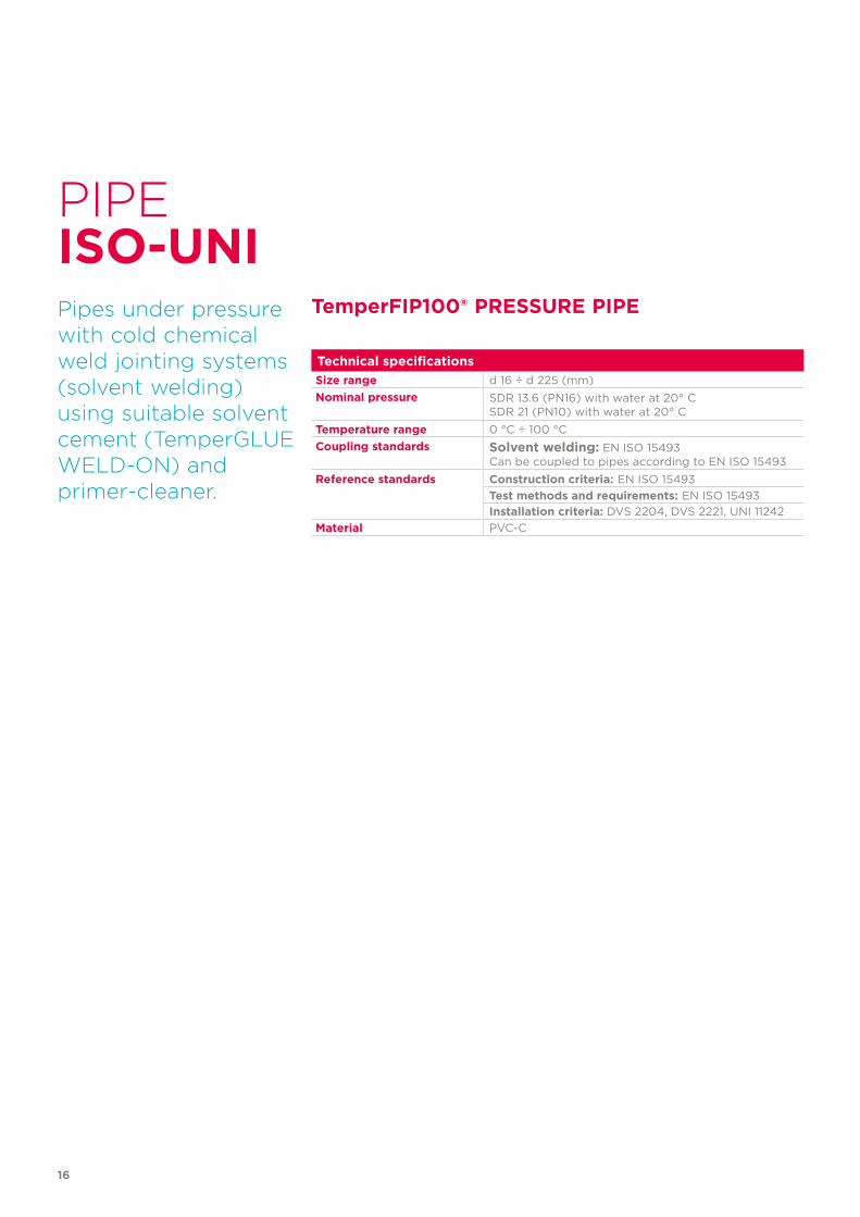
TemperFIP100® pressure pipe
16
Technical specificationsSize range d 16 ÷ d 225 (mm)Nominal pressure SDR 13.6 (PN16) with water at 20° C
SDR 21 (PN10) with water at 20° CTemperature range 0 °C ÷ 100 °CCoupling standards Solvent welding: EN ISO 15493
Can be coupled to pipes according to EN ISO 15493Reference standards Construction criteria: EN ISO 15493
Test methods and requirements: EN ISO 15493Installation criteria: DVS 2204, DVS 2221, UNI 11242
Material PVC-C
PIPE
Pipes under pressure with cold chemical weld jointing systems (solvent welding) using suitable solvent cement (TemperGLUE WELD-ON) and primer-cleaner.
TemperFIP100® PRESSURE PIPE
ISO-UNI
17
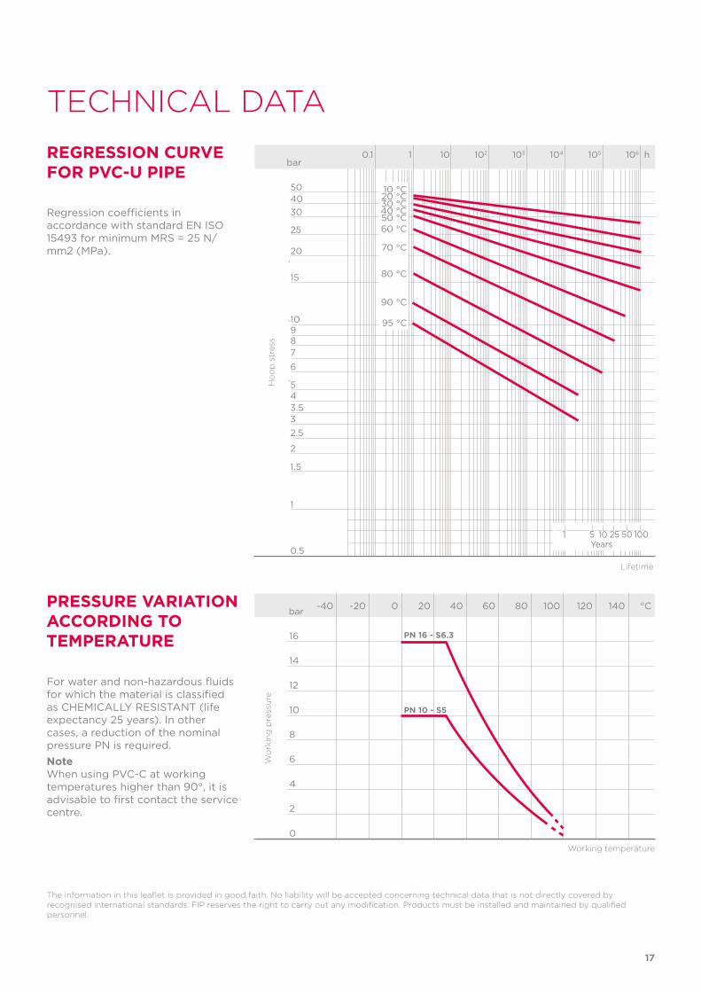
TECHNICAL DATAREGRESSION CURVE FOR PVC-U PIPE
Regression coefficients in accordance with standard EN ISO 15493 for minimum MRS = 25 N/mm2 (MPa).
The information in this leaflet is provided in good faith. No liability will be accepted concerning technical data that is not directly covered by recognised international standards. FIP reserves the right to carry out any modification. Products must be installed and maintained by qualified personnel.
PRESSURE VARIATION ACCORDING TO TEMPERATURE
For water and non-hazardous fluids for which the material is classified as CHEMICALLY RESISTANT (life expectancy 25 years). In other cases, a reduction of the nominal pressure PN is required.NoteWhen using PVC-C at working temperatures higher than 90°, it is advisable to first contact the service centre.
-40 -20 0 20 40 60 80 100 120 140 °C
16
14
12
10
8
6
4
2
0
Wo
rkin
g p
ress
ure
Working temperature
bar
PN 16 - S6.3
PN 10 - S5
Ho
op
str
ess
Lifetime
bar0.1 1 10 102 103 104 105 106 h
20
25
304050
15
10
0.5
1
1.5
2
2.533.545
6
789
20 °C10 °C
30 °C40 °C50 °C
70 °C
80 °C
90 °C
95 °C
60 °C
1 5 10 25 50 100Years
18
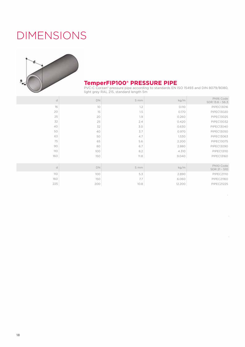
TemperFIP100® PRESSURE PIPEPVC-C Corzan® pressure pipe according to standards EN ISO 15493 and DIN 8079/8080, light grey RAL 215, standard length 5m
d DN S mm kg/m PN16 Code SDR 13.6 - S6.3
16 10 1.2 0.110 PIPEC13016
20 15 1.5 0.170 PIPEC13020
25 20 1.9 0.260 PIPEC13025
32 25 2.4 0.420 PIPEC13032
40 32 3.0 0.630 PIPEC13040
50 40 3.7 0.970 PIPEC13050
63 50 4.7 1.530 PIPEC13063
75 65 5.6 2.200 PIPEC13075
90 80 6.7 2.880 PIPEC13090
110 100 8.2 4.310 PIPEC13110
160 150 11.8 9.040 PIPEC13160
d DN S mm kg/m PN10 Code SDR 21 - S10
110 100 5.3 2.890 PIPEC21110
160 150 7.7 6.060 PIPEC21160
225 200 10.8 12.200 PIPEC21225
DIMENSIONS
19
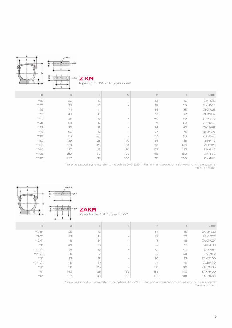
d a b C h I Code
**16 26 18 - 33 16 ZIKM016
**20 33 14 - 38 20 ZIKM020
**25 41 14 - 44 25 ZIKM025
**32 49 15 - 51 32 ZIKM032
**40 58 16 - 60 40 ZIKM040
**50 68 17 - 71 60 ZIKM050
**63 83 18 - 84 63 ZIKM063
**75 96 19 - 97 75 ZIKM075
**90 113 20 - 113 90 ZIKM090
**110 139 23 40 134 125 ZIKM110
**125 158 25 60 151 140 ZIKM125
**140 177 27 70 167 155 ZIKM140
**160 210 30 90 190 180 ZIKM160
**180 237 33 100 211 200 ZIKM180
ZIKMPipe clip for ISO-DIN pipes in PP*
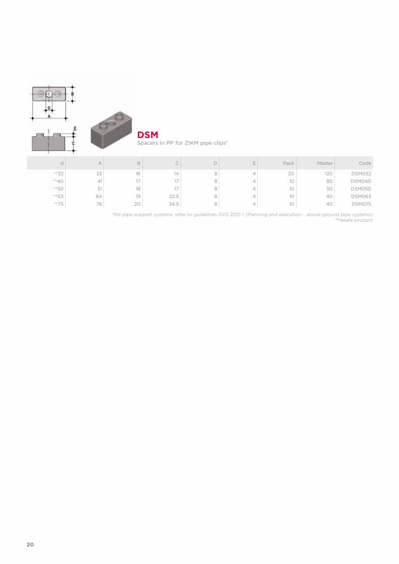
*for pipe support systems, refer to guidelines DVS 2210-1 (Planning and execution - above-ground pipe systems) **resale product
*for pipe support systems, refer to guidelines DVS 2210-1 (Planning and execution - above-ground pipe systems)**resale product
d a b C h I Code
**3/8” 26 13 - 34 16 ZAKM038
**1/2” 33 14 - 39 20 ZAKM012
**3/4” 41 14 - 45 25 ZAKM034
**1” 49 15 - 52 32 ZAKM100
**1” 1/4 58 16 - 61 40 ZAKM114
**1” 1/2 68 17 - 67 50 ZAKM112
**2” 83 18 - 80 63 ZAKM200
**2” 1/2 96 19 - 96 75 ZAKM212
**3” 118 20 - 110 90 ZAKM300
**4” 140 25 60 135 140 ZAKM400
**6” 197 30 90 196 180 ZAKM600
ZAKMPipe clip for ASTM pipes in PP*
20
*for pipe support systems, refer to guidelines DVS 2210-1 (Planning and execution - above-ground pipe systems)**resale product
d A B C D E Pack Master Code
**32 33 16 14 8 4 20 120 DSM032
**40 41 17 17 8 4 10 80 DSM040
**50 51 18 17 8 4 10 50 DSM050
**63 64 19 22.5 8 4 10 40 DSM063
**75 76 20 34.5 8 4 10 40 DSM075
DSMSpacers in PP for ZIKM pipe clips*
21
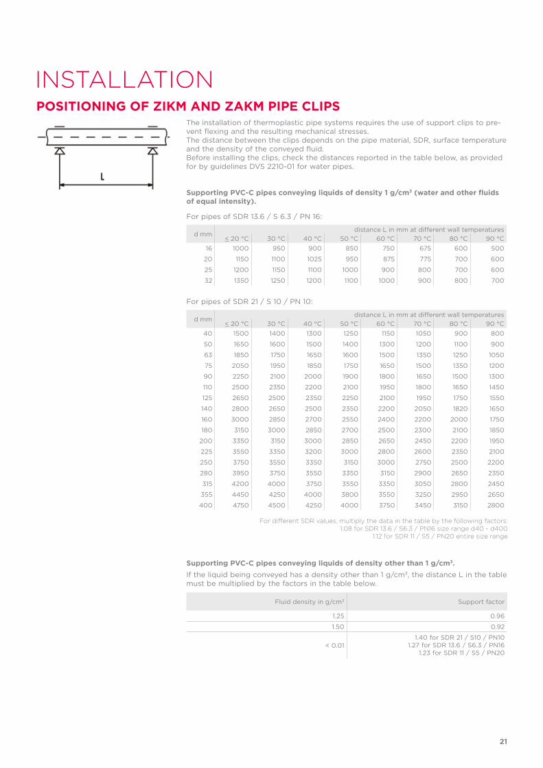
Supporting PVC-C pipes conveying liquids of density 1 g/cm3 (water and other fluids of equal intensity).
For pipes of SDR 13.6 / S 6.3 / PN 16:
For pipes of SDR 21 / S 10 / PN 10:
Supporting PVC-C pipes conveying liquids of density other than 1 g/cm3. If the liquid being conveyed has a density other than 1 g/cm3, the distance L in the table must be multiplied by the factors in the table below.
INSTALLATION
The installation of thermoplastic pipe systems requires the use of support clips to pre-vent flexing and the resulting mechanical stresses.The distance between the clips depends on the pipe material, SDR, surface temperature and the density of the conveyed fluid.Before installing the clips, check the distances reported in the table below, as provided for by guidelines DVS 2210-01 for water pipes.
d mmdistance L in mm at different wall temperatures
< 20 °C 30 °C 40 °C 50 °C 60 °C 70 °C 80 °C 90 °C16 1000 950 900 850 750 675 600 500
20 1150 1100 1025 950 875 775 700 600
25 1200 1150 1100 1000 900 800 700 600
32 1350 1250 1200 1100 1000 900 800 700
d mmdistance L in mm at different wall temperatures
< 20 °C 30 °C 40 °C 50 °C 60 °C 70 °C 80 °C 90 °C40 1500 1400 1300 1250 1150 1050 900 800
50 1650 1600 1500 1400 1300 1200 1100 900
63 1850 1750 1650 1600 1500 1350 1250 1050
75 2050 1950 1850 1750 1650 1500 1350 1200
90 2250 2100 2000 1900 1800 1650 1500 1300
110 2500 2350 2200 2100 1950 1800 1650 1450
125 2650 2500 2350 2250 2100 1950 1750 1550
140 2800 2650 2500 2350 2200 2050 1820 1650
160 3000 2850 2700 2550 2400 2200 2000 1750
180 3150 3000 2850 2700 2500 2300 2100 1850
200 3350 3150 3000 2850 2650 2450 2200 1950
225 3550 3350 3200 3000 2800 2600 2350 2100
250 3750 3550 3350 3150 3000 2750 2500 2200
280 3950 3750 3550 3350 3150 2900 2650 2350
315 4200 4000 3750 3550 3350 3050 2800 2450
355 4450 4250 4000 3800 3550 3250 2950 2650
400 4750 4500 4250 4000 3750 3450 3150 2800
Fluid density in g/cm3 Support factor
1.25 0.96
1.50 0.92
< 0.011.40 for SDR 21 / S10 / PN10
1.27 for SDR 13.6 / S6.3 / PN161.23 for SDR 11 / S5 / PN20
POSITIONING OF ZIKM AND ZAKM PIPE CLIPS
For different SDR values, multiply the data in the table by the following factors:1.08 for SDR 13.6 / S6.3 / PN16 size range d40 - d400
1.12 for SDR 11 / S5 / PN20 entire size range

ISO-UNI FITTINGSPVC-C
TemperFIP100® solvent weld fittings, metric series
24
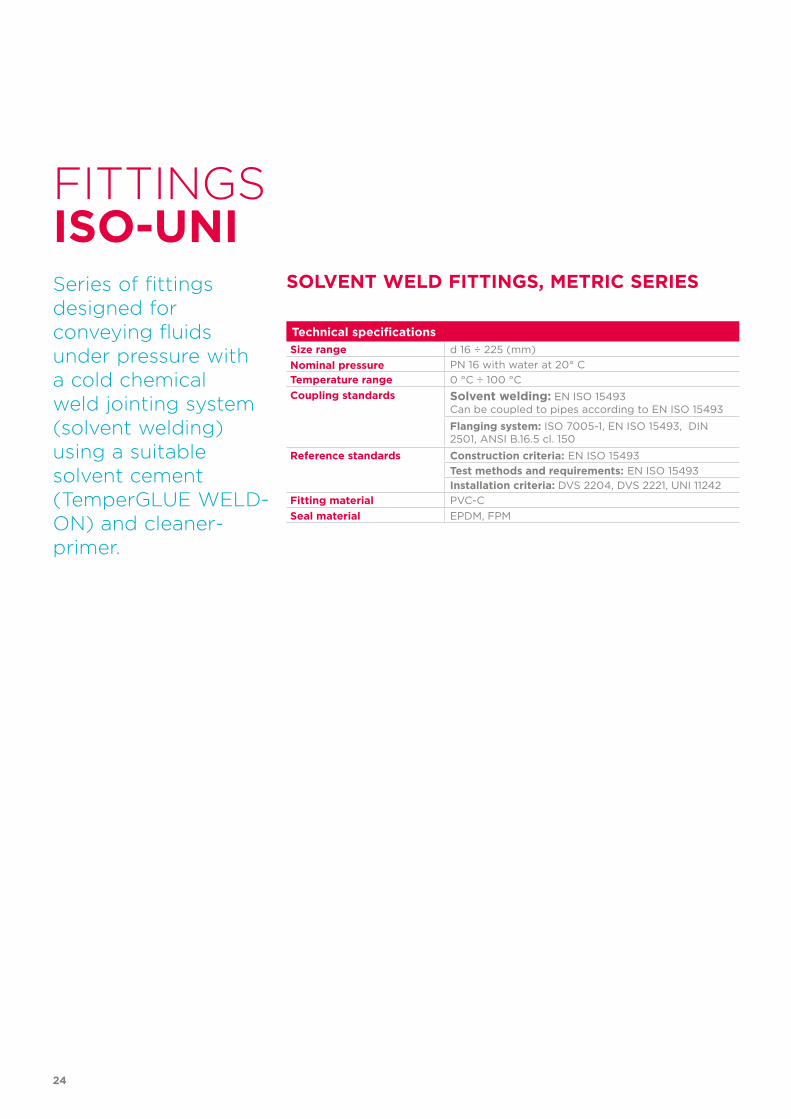
Technical specificationsSize range d 16 ÷ 225 (mm)Nominal pressure PN 16 with water at 20° CTemperature range 0 °C ÷ 100 °CCoupling standards Solvent welding: EN ISO 15493
Can be coupled to pipes according to EN ISO 15493
Flanging system: ISO 7005-1, EN ISO 15493, DIN 2501, ANSI B.16.5 cl. 150
Reference standards Construction criteria: EN ISO 15493Test methods and requirements: EN ISO 15493Installation criteria: DVS 2204, DVS 2221, UNI 11242
Fitting material PVC-CSeal material EPDM, FPM
FITTINGS
Series of fittings designed forconveying fluidsunder pressure with a cold chemical weld jointing system (solvent welding) using a suitable solvent cement (TemperGLUE WELD-ON) and cleaner-primer.
SOLVENT WELD FITTINGS, METRIC SERIES
ISO-UNI
25
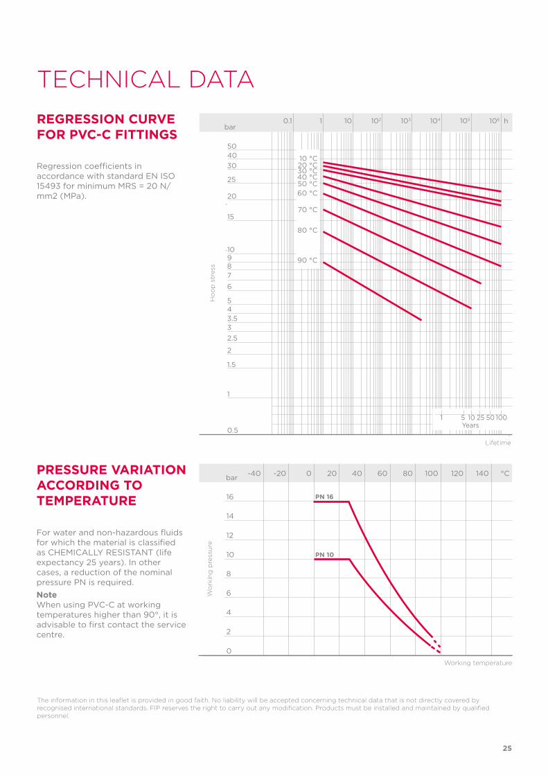
TECHNICAL DATAREGRESSION CURVE FOR PVC-C FITTINGS
Regression coefficients in accordance with standard EN ISO 15493 for minimum MRS = 20 N/mm2 (MPa).
The information in this leaflet is provided in good faith. No liability will be accepted concerning technical data that is not directly covered by recognised international standards. FIP reserves the right to carry out any modification. Products must be installed and maintained by qualified personnel.
PRESSURE VARIATION ACCORDING TO TEMPERATURE
-40 -20 0 20 40 60 80 100 120 140 °C
16
14
12
10
8
6
4
2
0
Wo
rkin
g p
ress
ure
Working temperature
bar
PN 16
PN 10
Ho
op
str
ess
Lifetime
bar0.1 1 10 102 103 104 105 106 h
20
25
304050
15
10
0.5
1
1.5
2
2.533.545
6
789
20 °C10 °C
30 °C40 °C50 °C
70 °C
80 °C
90 °C
60 °C
1 5 10 25 50 100Years
For water and non-hazardous fluids for which the material is classified as CHEMICALLY RESISTANT (life expectancy 25 years). In other cases, a reduction of the nominal pressure PN is required.NoteWhen using PVC-C at working temperatures higher than 90°, it is advisable to first contact the service centre.
26
Fig. B
Fig. A
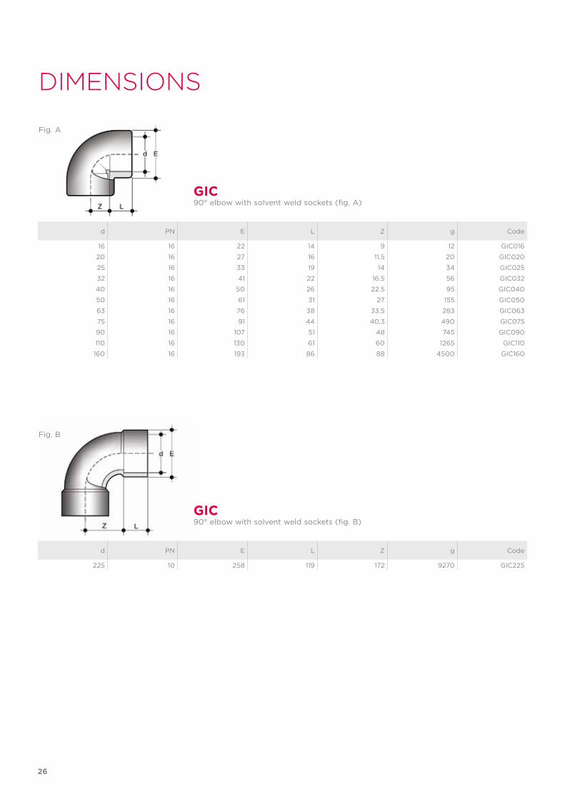
DIMENSIONS
d PN E L Z g Code
16 16 22 14 9 12 GIC016
20 16 27 16 11.5 20 GIC020
25 16 33 19 14 34 GIC025
32 16 41 22 16.5 56 GIC032
40 16 50 26 22.5 95 GIC040
50 16 61 31 27 155 GIC050
63 16 76 38 33.5 283 GIC063
75 16 91 44 40.3 490 GIC075
90 16 107 51 48 745 GIC090
110 16 130 61 60 1265 GIC110
160 16 193 86 88 4500 GIC160
d PN E L Z g Code
225 10 258 119 172 9270 GIC225
GIC
GIC
90° elbow with solvent weld sockets (fig. A)
90° elbow with solvent weld sockets (fig. B)
27
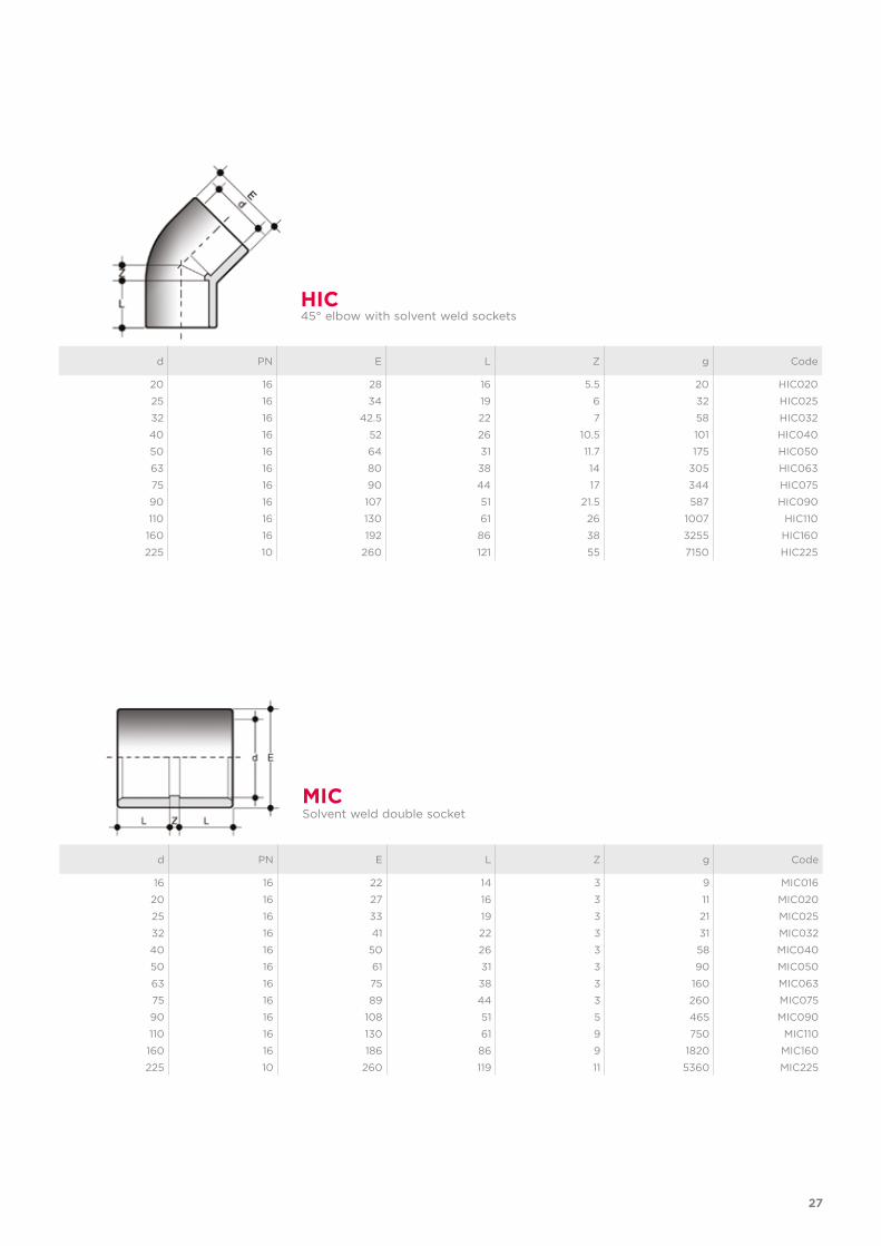
d PN E L Z g Code
20 16 28 16 5.5 20 HIC020
25 16 34 19 6 32 HIC025
32 16 42.5 22 7 58 HIC032
40 16 52 26 10.5 101 HIC040
50 16 64 31 11.7 175 HIC050
63 16 80 38 14 305 HIC063
75 16 90 44 17 344 HIC075
90 16 107 51 21.5 587 HIC090
110 16 130 61 26 1007 HIC110
160 16 192 86 38 3255 HIC160
225 10 260 121 55 7150 HIC225
HIC45° elbow with solvent weld sockets
d PN E L Z g Code
16 16 22 14 3 9 MIC016
20 16 27 16 3 11 MIC020
25 16 33 19 3 21 MIC025
32 16 41 22 3 31 MIC032
40 16 50 26 3 58 MIC040
50 16 61 31 3 90 MIC050
63 16 75 38 3 160 MIC063
75 16 89 44 3 260 MIC075
90 16 108 51 5 465 MIC090
110 16 130 61 9 750 MIC110
160 16 186 86 9 1820 MIC160
225 10 260 119 11 5360 MIC225
MICSolvent weld double socket
28
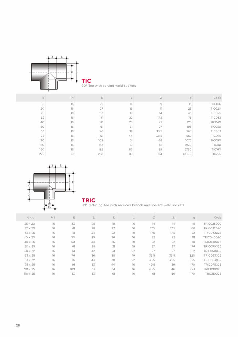
d x d1 PN E E1 L L1 Z Z1 g Code
25 x 20 16 33 28 19 16 14 14 41 TRIC025020
32 x 20 16 41 28 22 16 17.5 17.5 66 TRIC032020
32 x 25 16 41 34 22 19 17.5 17.5 72 TRIC032025
40 x 20 16 50 29 26 16 22 22 111 TRIC040020
40 x 25 16 50 34 26 19 22 22 111 TRIC040025
50 x 25 16 61 35 31 19 27 27 176 TRIC050025
50 x 32 16 61 42 31 22 27 27 182 TRIC050032
63 x 25 16 76 36 38 19 33.5 33.5 320 TRIC063025
63 x 32 16 76 43 38 22 33.5 33.5 325 TRIC063032
75 x 25 16 91 33 44 16 40.5 39 470 TRIC075025
90 x 25 16 109 33 51 16 48.5 46 773 TRIC090025
110 x 25 16 133 33 61 16 61 56 1170 TRIC110025
TRIC90° reducing Tee with reduced branch and solvent weld sockets
d PN E L Z g Code
16 16 22 14 9 15 TIC016
20 16 27 16 11 25 TIC020
25 16 33 19 14 45 TIC025
32 16 41 22 17.5 75 TIC032
40 16 50 26 22 125 TIC040
50 16 61 31 27 195 TIC050
63 16 76 38 33.5 394 TIC063
75 16 91 44 38.5 667 TIC075
90 16 109 51 48 1075 TIC090
110 16 133 61 61 1920 TIC110
160 16 192 86 89 5730 TIC160
225 10 258 119 114 10800 TIC225
TIC90° Tee with solvent weld sockets
29
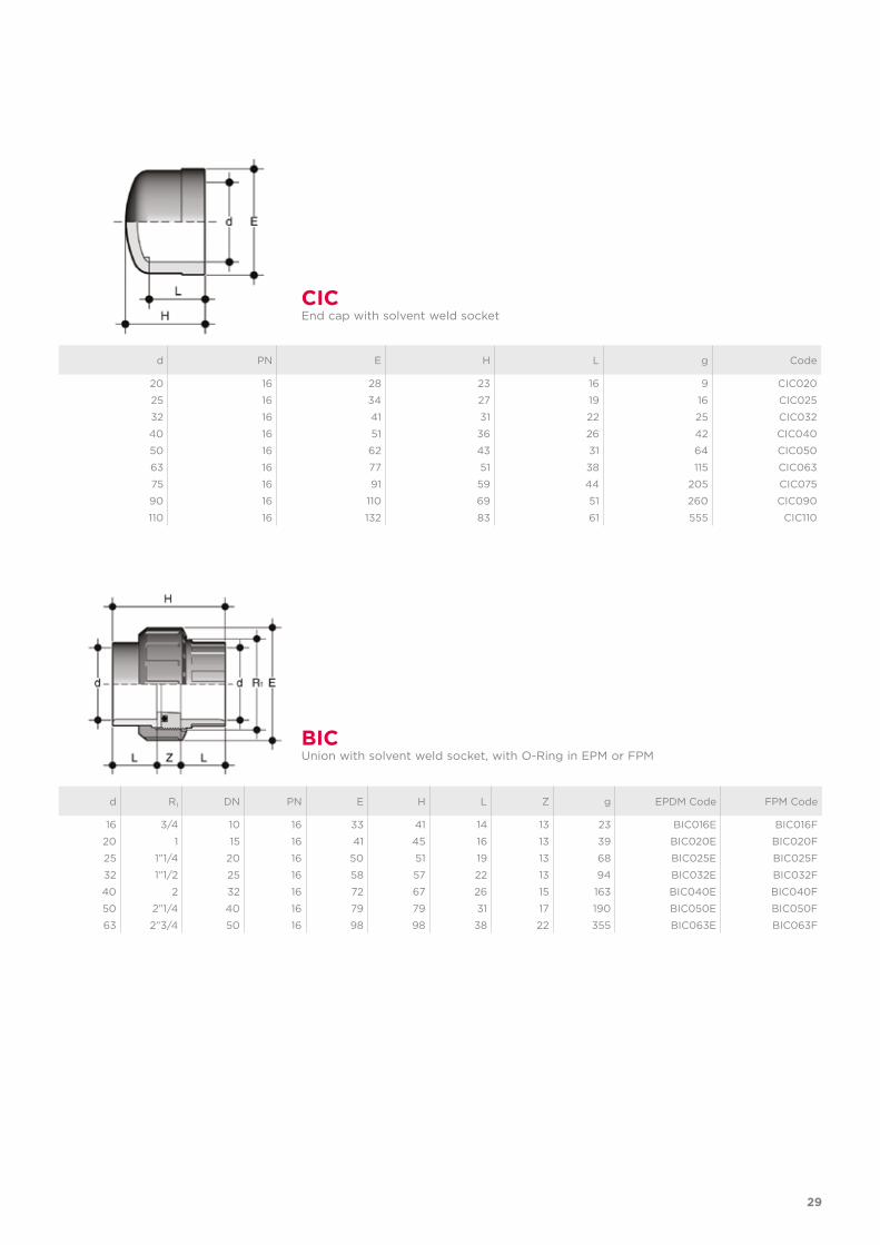
d PN E H L g Code
20 16 28 23 16 9 CIC020
25 16 34 27 19 16 CIC025
32 16 41 31 22 25 CIC032
40 16 51 36 26 42 CIC040
50 16 62 43 31 64 CIC050
63 16 77 51 38 115 CIC063
75 16 91 59 44 205 CIC075
90 16 110 69 51 260 CIC090
110 16 132 83 61 555 CIC110
CICEnd cap with solvent weld socket
d R1 DN PN E H L Z g EPDM Code FPM Code
16 3/4 10 16 33 41 14 13 23 BIC016E BIC016F
20 1 15 16 41 45 16 13 39 BIC020E BIC020F
25 1”1/4 20 16 50 51 19 13 68 BIC025E BIC025F
32 1”1/2 25 16 58 57 22 13 94 BIC032E BIC032F
40 2 32 16 72 67 26 15 163 BIC040E BIC040F
50 2”1/4 40 16 79 79 31 17 190 BIC050E BIC050F
63 2”3/4 50 16 98 98 38 22 355 BIC063E BIC063F
BICUnion with solvent weld socket, with O-Ring in EPM or FPM
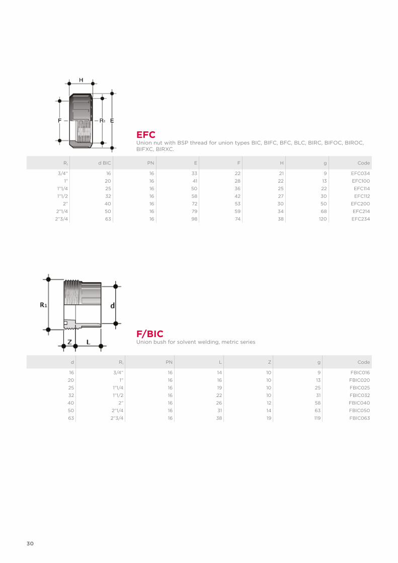
d R1 PN L Z g Code
16 3/4” 16 14 10 9 FBIC016
20 1” 16 16 10 13 FBIC020
25 1”1/4 16 19 10 25 FBIC025
32 1”1/2 16 22 10 31 FBIC032
40 2” 16 26 12 58 FBIC040
50 2”1/4 16 31 14 63 FBIC050
63 2”3/4 16 38 19 119 FBIC063
F/BICUnion bush for solvent welding, metric series
30
R1 d BIC PN E F H g Code
3/4” 16 16 33 22 21 9 EFC034
1” 20 16 41 28 22 13 EFC100
1”1/4 25 16 50 36 25 22 EFC114
1”1/2 32 16 58 42 27 30 EFC112
2” 40 16 72 53 30 50 EFC200
2”1/4 50 16 79 59 34 68 EFC214
2”3/4 63 16 98 74 38 120 EFC234
EFCUnion nut with BSP thread for union types BIC, BIFC, BFC, BLC, BIRC, BIFOC, BIROC, BIFXC, BIRXC.
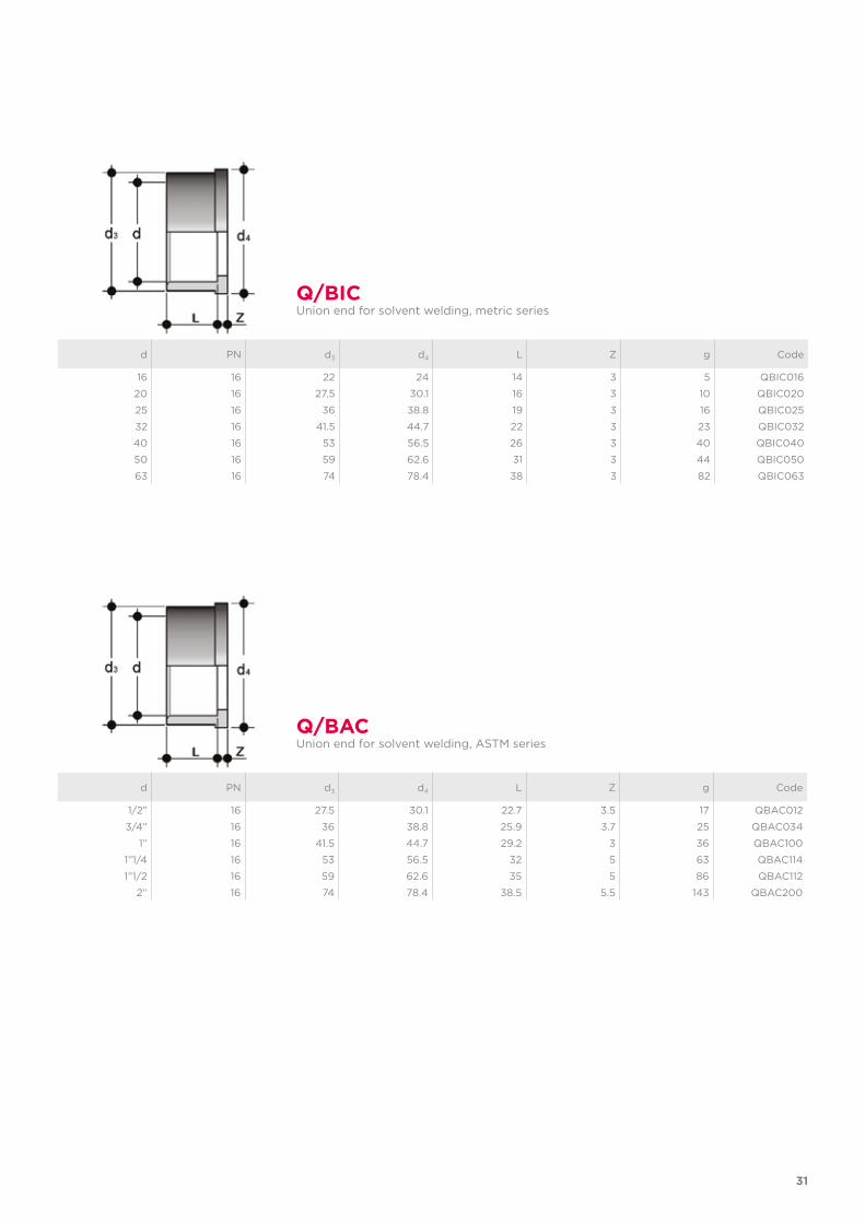
d PN d3 d4 L Z g Code
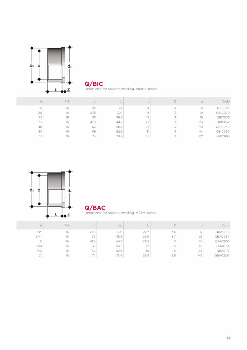
1/2” 16 27.5 30.1 22.7 3.5 17 QBAC012
3/4” 16 36 38.8 25.9 3.7 25 QBAC034
1” 16 41.5 44.7 29.2 3 36 QBAC100
1”1/4 16 53 56.5 32 5 63 QBAC114
1”1/2 16 59 62.6 35 5 86 QBAC112
2” 16 74 78.4 38.5 5.5 143 QBAC200
Q/BACUnion end for solvent welding, ASTM series
d PN d3 d4 L Z g Code
16 16 22 24 14 3 5 QBIC016
20 16 27.5 30.1 16 3 10 QBIC020
25 16 36 38.8 19 3 16 QBIC025
32 16 41.5 44.7 22 3 23 QBIC032
40 16 53 56.5 26 3 40 QBIC040
50 16 59 62.6 31 3 44 QBIC050
63 16 74 78.4 38 3 82 QBIC063
Q/BICUnion end for solvent welding, metric series
31
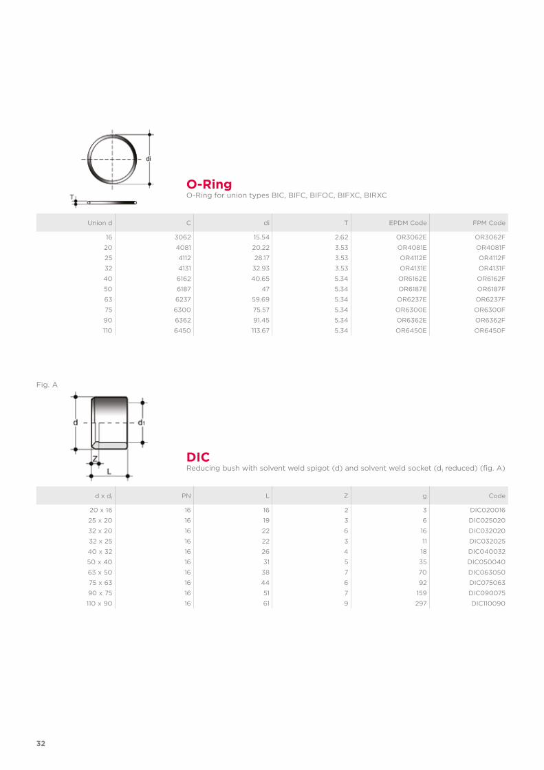
Union d C di T EPDM Code FPM Code
16 3062 15.54 2.62 OR3062E OR3062F
20 4081 20.22 3.53 OR4081E OR4081F
25 4112 28.17 3.53 OR4112E OR4112F
32 4131 32.93 3.53 OR4131E OR4131F
40 6162 40.65 5.34 OR6162E OR6162F
50 6187 47 5.34 OR6187E OR6187F
63 6237 59.69 5.34 OR6237E OR6237F
75 6300 75.57 5.34 OR6300E OR6300F
90 6362 91.45 5.34 OR6362E OR6362F
110 6450 113.67 5.34 OR6450E OR6450F
O-RingO-Ring for union types BIC, BIFC, BIFOC, BIFXC, BIRXC
32
Fig. A
d x d1 PN L Z g Code
20 x 16 16 16 2 3 DIC020016
25 x 20 16 19 3 6 DIC025020
32 x 20 16 22 6 16 DIC032020
32 x 25 16 22 3 11 DIC032025
40 x 32 16 26 4 18 DIC040032
50 x 40 16 31 5 35 DIC050040
63 x 50 16 38 7 70 DIC063050
75 x 63 16 44 6 92 DIC075063
90 x 75 16 51 7 159 DIC090075
110 x 90 16 61 9 297 DIC110090
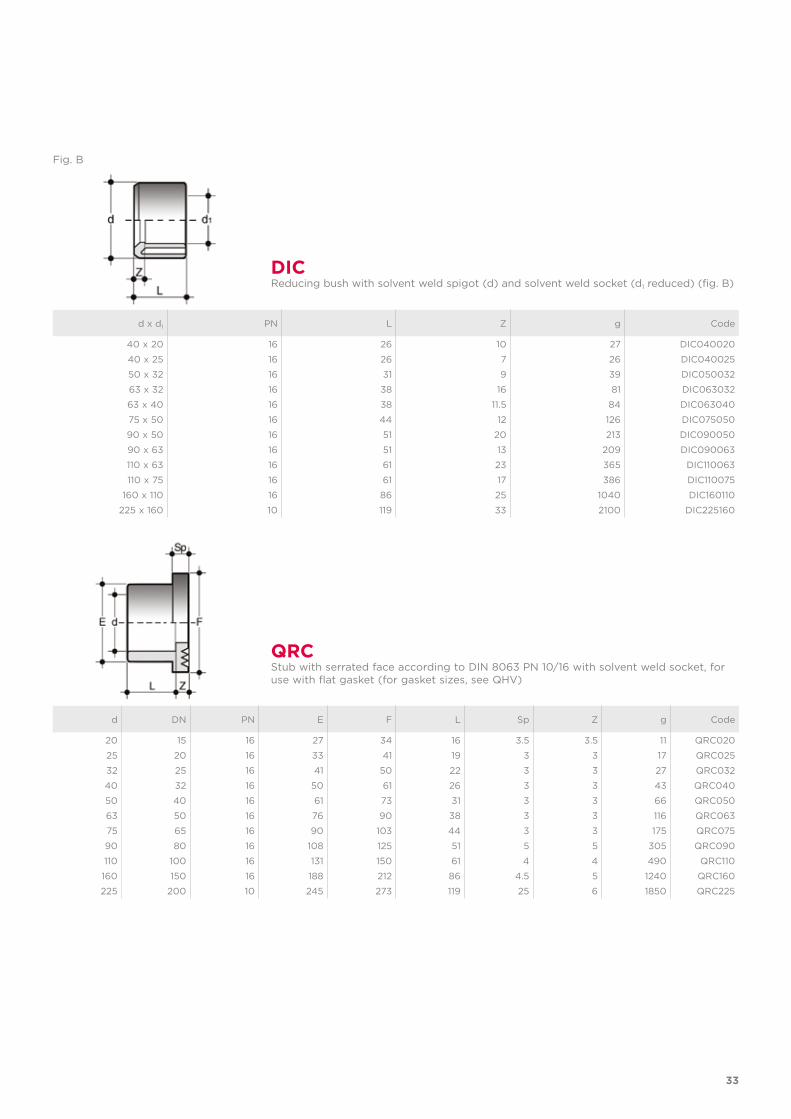
DICReducing bush with solvent weld spigot (d) and solvent weld socket (d1 reduced) (fig. A)
33
QRCStub with serrated face according to DIN 8063 PN 10/16 with solvent weld socket, for use with flat gasket (for gasket sizes, see QHV)
d DN PN E F L Sp Z g Code
20 15 16 27 34 16 3.5 3.5 11 QRC020
25 20 16 33 41 19 3 3 17 QRC025
32 25 16 41 50 22 3 3 27 QRC032
40 32 16 50 61 26 3 3 43 QRC040
50 40 16 61 73 31 3 3 66 QRC050
63 50 16 76 90 38 3 3 116 QRC063
75 65 16 90 103 44 3 3 175 QRC075
90 80 16 108 125 51 5 5 305 QRC090
110 100 16 131 150 61 4 4 490 QRC110
160 150 16 188 212 86 4.5 5 1240 QRC160
225 200 10 245 273 119 25 6 1850 QRC225
Fig. B
d x d1 PN L Z g Code
40 x 20 16 26 10 27 DIC040020
40 x 25 16 26 7 26 DIC040025
50 x 32 16 31 9 39 DIC050032
63 x 32 16 38 16 81 DIC063032
63 x 40 16 38 11.5 84 DIC063040
75 x 50 16 44 12 126 DIC075050
90 x 50 16 51 20 213 DIC090050
90 x 63 16 51 13 209 DIC090063
110 x 63 16 61 23 365 DIC110063
110 x 75 16 61 17 386 DIC110075
160 x 110 16 86 25 1040 DIC160110
225 x 160 10 119 33 2100 DIC225160
DICReducing bush with solvent weld spigot (d) and solvent weld socket (d1 reduced) (fig. B)
34
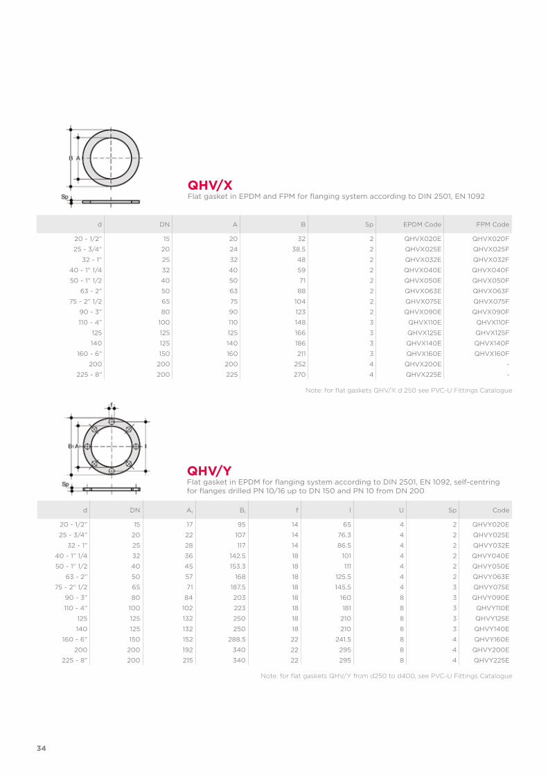
d DN A B Sp EPDM Code FPM Code
20 - 1/2” 15 20 32 2 QHVX020E QHVX020F
25 - 3/4” 20 24 38.5 2 QHVX025E QHVX025F
32 - 1” 25 32 48 2 QHVX032E QHVX032F
40 - 1” 1/4 32 40 59 2 QHVX040E QHVX040F
50 - 1” 1/2 40 50 71 2 QHVX050E QHVX050F
63 - 2” 50 63 88 2 QHVX063E QHVX063F
75 - 2” 1/2 65 75 104 2 QHVX075E QHVX075F
90 - 3” 80 90 123 2 QHVX090E QHVX090F
110 - 4” 100 110 148 3 QHVX110E QHVX110F
125 125 125 166 3 QHVX125E QHVX125F
140 125 140 186 3 QHVX140E QHVX140F
160 - 6” 150 160 211 3 QHVX160E QHVX160F
200 200 200 252 4 QHVX200E -
225 - 8” 200 225 270 4 QHVX225E -
QHV/X Flat gasket in EPDM and FPM for flanging system according to DIN 2501, EN 1092
d DN A1 B1 f I U Sp Code
20 - 1/2” 15 17 95 14 65 4 2 QHVY020E
25 - 3/4” 20 22 107 14 76.3 4 2 QHVY025E
32 - 1” 25 28 117 14 86.5 4 2 QHVY032E
40 - 1” 1/4 32 36 142.5 18 101 4 2 QHVY040E
50 - 1” 1/2 40 45 153.3 18 111 4 2 QHVY050E
63 - 2” 50 57 168 18 125.5 4 2 QHVY063E
75 - 2” 1/2 65 71 187.5 18 145.5 4 3 QHVY075E
90 - 3” 80 84 203 18 160 8 3 QHVY090E
110 - 4” 100 102 223 18 181 8 3 QHVY110E
125 125 132 250 18 210 8 3 QHVY125E
140 125 132 250 18 210 8 3 QHVY140E
160 - 6” 150 152 288.5 22 241.5 8 4 QHVY160E
200 200 192 340 22 295 8 4 QHVY200E
225 - 8” 200 215 340 22 295 8 4 QHVY225E
QHV/YFlat gasket in EPDM for flanging system according to DIN 2501, EN 1092, self-centring for flanges drilled PN 10/16 up to DN 150 and PN 10 from DN 200
Note: for flat gaskets QHV/X d 250 see PVC-U Fittings Catalogue
Note: for flat gaskets QHV/Y from d250 to d400, see PVC-U Fittings Catalogue
35
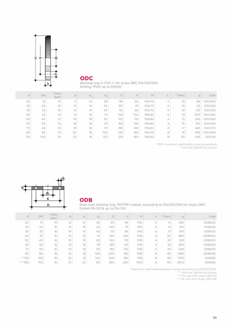
d DN *PMA(bar) b d2 d6 D K M n **(Nm) g Code
20 15 10 11 14 28 96 65 M12x70 4 10 66 ODC020
25 20 10 12 14 34 107 75 M12x70 4 10 93 ODC025
32 25 10 14 14 42 116 85 M12x70 4 10 122 ODC032
40 32 10 15 18 51 142 100 M16x85 4 13 200 ODC040
50 40 10 16 18 62 153 110 M16x85 4 13 245 ODC050
63 50 10 18 18 78 168 125 M16x95 4 15 310 ODC063
75 65 10 19 18 91 188 145 M16x95 4 17 425 ODC075
90 80 10 20 18 109 199 160 M16x105 8 18 455 ODC090
110 100 10 22 18 132 219 180 M16x105 8 20 545 ODC110
ODCBacking ring in PVC-C for stubs QRC EN/ISO/DIN.Drilling: PN10 up to DN100
ODBSteel core backing ring, PP/FRP coated, according to EN/ISO/DIN for stubs QRC Drilled PN 10/16 up to DN 150
d DN *PMA(bar) b d2 d6 D k M n **(Nm) g Code
20 15 16 12 14 28 95 65 M12 4 15 290 ODB020
25 20 16 14 14 34 105 75 M12 4 15 410 ODB025
32 25 16 14 14 42 115 85 M12 4 15 610 ODB032
40 32 16 16 18 51 140 100 M16 4 20 880 ODB040
50 40 16 16 18 62 150 110 M16 4 30 810 ODB050
63 50 16 19 18 78 165 125 M16 4 35 940 ODB063
75 65 16 19 18 92 185 145 M16 4 40 1210 ODB075
90 80 16 21 18 109 200 160 M16 8 40 1480 ODB090
***125 100 16 22 18 134 220 180 M16 8 40 1570 ODB125
****180 150 16 27 22 191 285 240 M20 8 60 3470 ODB180
*PMA maximum admissible working pressure**nominal tightening torque
*maximum admissible pressure values according to EN/ISO/DIN. ** nominal tightening torque
*** for use with stubs QRC110*** for use with stubs QRC160
36
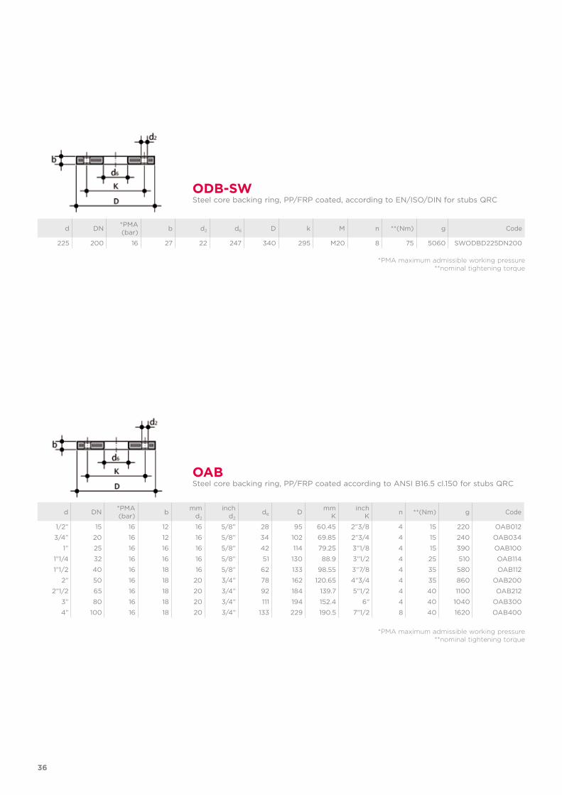
d DN *PMA(bar) b d2 d6 D k M n **(Nm) g Code
225 200 16 27 22 247 340 295 M20 8 75 5060 SWODBD225DN200
ODB-SWSteel core backing ring, PP/FRP coated, according to EN/ISO/DIN for stubs QRC
*PMA maximum admissible working pressure**nominal tightening torque
*PMA maximum admissible working pressure**nominal tightening torque
OABSteel core backing ring, PP/FRP coated according to ANSI B16.5 cl.150 for stubs QRC
d DN *PMA(bar) b mm
d2
inchd2
d6 D mmK
inchK n **(Nm) g Code
1/2” 15 16 12 16 5/8” 28 95 60.45 2”3/8 4 15 220 OAB012
3/4” 20 16 12 16 5/8” 34 102 69.85 2”3/4 4 15 240 OAB034
1” 25 16 16 16 5/8” 42 114 79.25 3”1/8 4 15 390 OAB100
1”1/4 32 16 16 16 5/8” 51 130 88.9 3”1/2 4 25 510 OAB114
1”1/2 40 16 18 16 5/8” 62 133 98.55 3”7/8 4 35 580 OAB112
2” 50 16 18 20 3/4” 78 162 120.65 4”3/4 4 35 860 OAB200
2”1/2 65 16 18 20 3/4” 92 184 139.7 5”1/2 4 40 1100 OAB212
3” 80 16 18 20 3/4” 111 194 152.4 6” 4 40 1040 OAB300
4” 100 16 18 20 3/4” 133 229 190.5 7”1/2 8 40 1620 OAB400
37
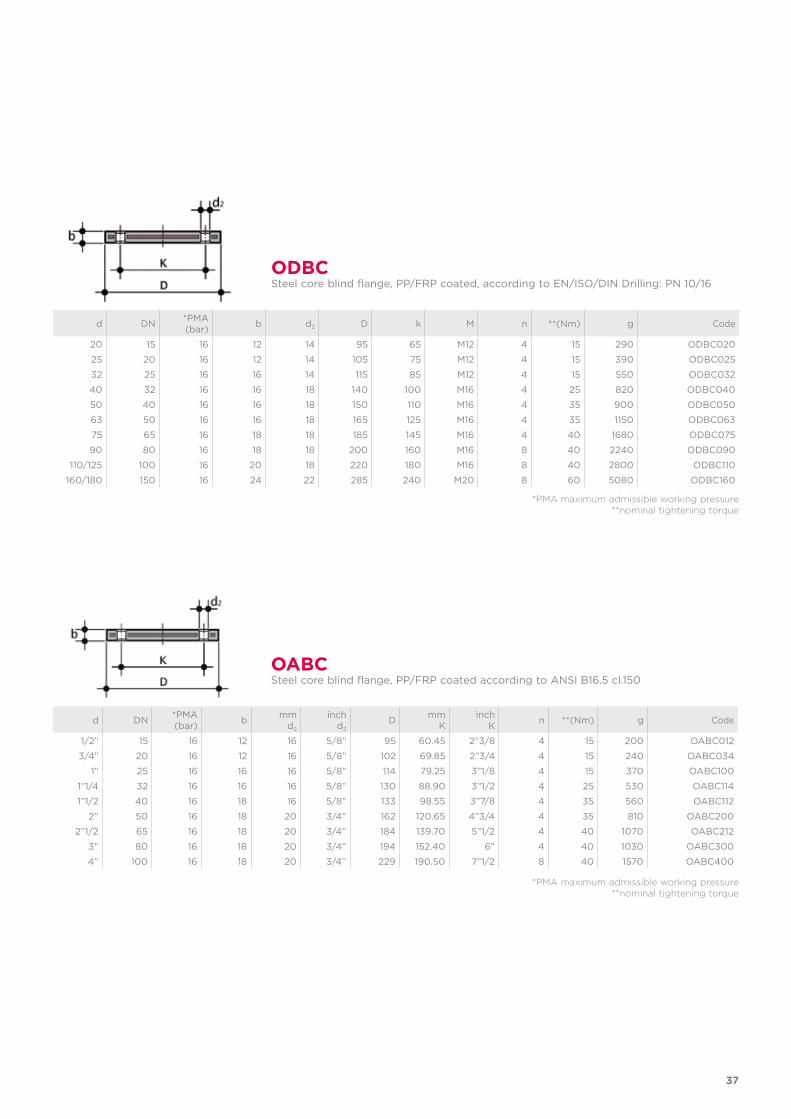
*PMA maximum admissible working pressure**nominal tightening torque
*PMA maximum admissible working pressure**nominal tightening torque
ODBCSteel core blind flange, PP/FRP coated, according to EN/ISO/DIN Drilling: PN 10/16
d DN *PMA(bar) b d2 D k M n **(Nm) g Code
20 15 16 12 14 95 65 M12 4 15 290 ODBC020
25 20 16 12 14 105 75 M12 4 15 390 ODBC025
32 25 16 16 14 115 85 M12 4 15 550 ODBC032
40 32 16 16 18 140 100 M16 4 25 820 ODBC040
50 40 16 16 18 150 110 M16 4 35 900 ODBC050
63 50 16 16 18 165 125 M16 4 35 1150 ODBC063
75 65 16 18 18 185 145 M16 4 40 1680 ODBC075
90 80 16 18 18 200 160 M16 8 40 2240 ODBC090
110/125 100 16 20 18 220 180 M16 8 40 2800 ODBC110
160/180 150 16 24 22 285 240 M20 8 60 5080 ODBC160
OABCSteel core blind flange, PP/FRP coated according to ANSI B16.5 cl.150
d DN *PMA(bar) b mm
d2
inchd2
D mmK
inchK n **(Nm) g Code
1/2” 15 16 12 16 5/8” 95 60.45 2”3/8 4 15 200 OABC012
3/4” 20 16 12 16 5/8” 102 69.85 2”3/4 4 15 240 OABC034
1” 25 16 16 16 5/8” 114 79.25 3”1/8 4 15 370 OABC100
1”1/4 32 16 16 16 5/8” 130 88.90 3”1/2 4 25 530 OABC114
1”1/2 40 16 18 16 5/8” 133 98.55 3”7/8 4 35 560 OABC112
2” 50 16 18 20 3/4” 162 120.65 4”3/4 4 35 810 OABC200
2”1/2 65 16 18 20 3/4” 184 139.70 5”1/2 4 40 1070 OABC212
3” 80 16 18 20 3/4” 194 152.40 6” 4 40 1030 OABC300
4” 100 16 18 20 3/4” 229 190.50 7”1/2 8 40 1570 OABC400

ISO-BSP FITTINGSPVC-C
TemperFIP100® adapter fittings
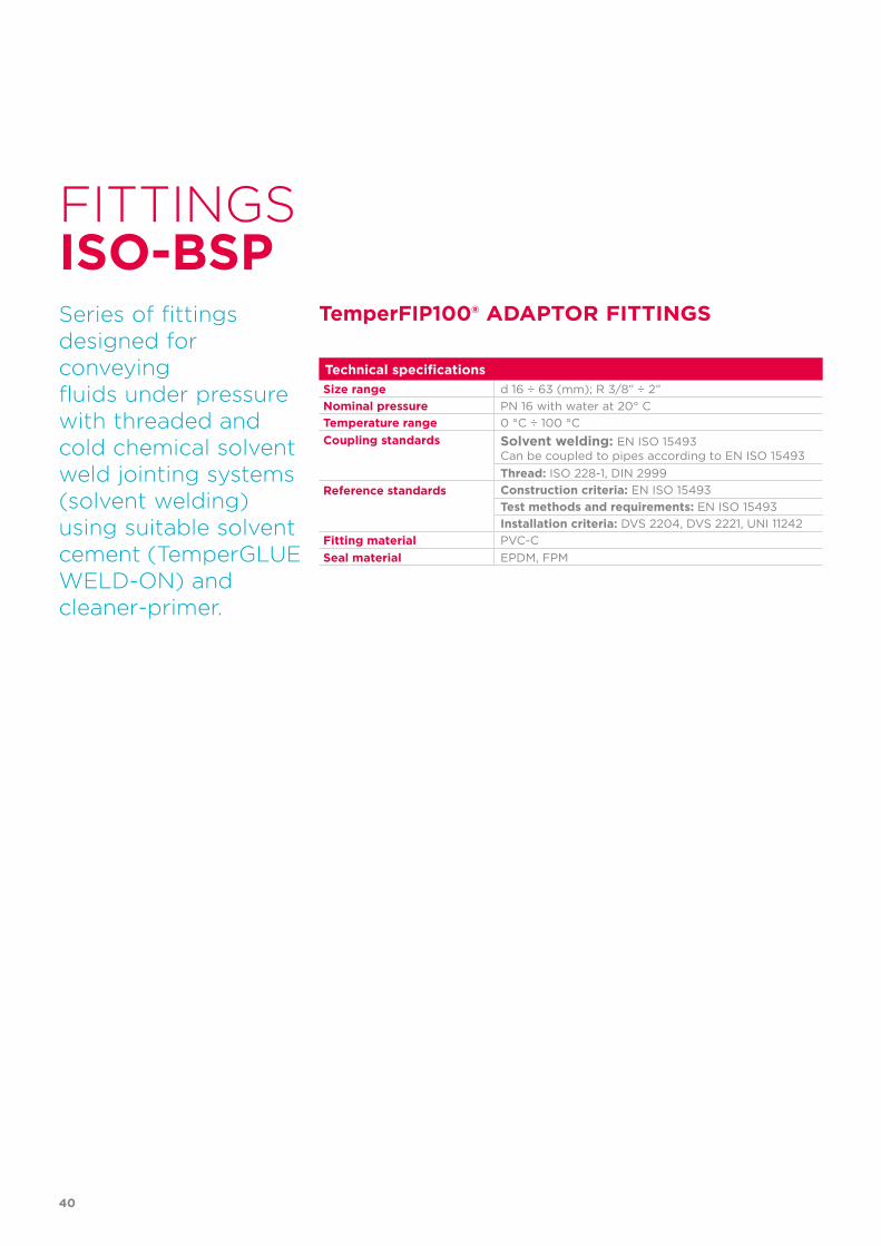
Technical specificationsSize range d 16 ÷ 63 (mm); R 3/8” ÷ 2”Nominal pressure PN 16 with water at 20° CTemperature range 0 °C ÷ 100 °CCoupling standards Solvent welding: EN ISO 15493
Can be coupled to pipes according to EN ISO 15493Thread: ISO 228-1, DIN 2999
Reference standards Construction criteria: EN ISO 15493Test methods and requirements: EN ISO 15493Installation criteria: DVS 2204, DVS 2221, UNI 11242
Fitting material PVC-CSeal material EPDM, FPM
FITTINGS
Series of fittings designed for conveyingfluids under pressure with threaded and cold chemical solvent weld jointing systems (solvent welding) using suitable solvent cement (TemperGLUE WELD-ON) and cleaner-primer.
TemperFIP100® ADAPTOR FITTINGS
ISO-BSP
40

41
TECHNICAL DATAREGRESSION CURVE FOR PVC-C FITTINGS
Regression coefficients in accordance with standard EN ISO 15493 for minimum MRS = 20 N/mm2 (MPa).
The information in this leaflet is provided in good faith. No liability will be accepted concerning technical data that is not directly covered by recognised international standards. FIP reserves the right to carry out any modification. Products must be installed and maintained by qualified personnel.
PRESSURE VARIATION ACCORDING TO TEMPERATURE
-40 -20 0 20 40 60 80 100 120 140 °C
16
14
12
10
8
6
4
2
0
Wo
rkin
g p
ress
ure
Working temperature
bar
PN 16
PN 10
Ho
op
str
ess
Lifetime
bar0.1 1 10 102 103 104 105 106 h
20
25
304050
15
10
0.5
1
1.5
2
2.533.545
6
789
20 °C10 °C
30 °C40 °C50 °C
70 °C
80 °C
90 °C
60 °C
1 5 10 25 50 100Years
For water and non-hazardous fluids for which the material is classified as CHEMICALLY RESISTANT (life expectancy 25 years). In other cases, a reduction of the nominal pressure PN is required.NoteWhen using PVC-C at working temperatures higher than 90°, it is advisable to first contact the service centre.
42
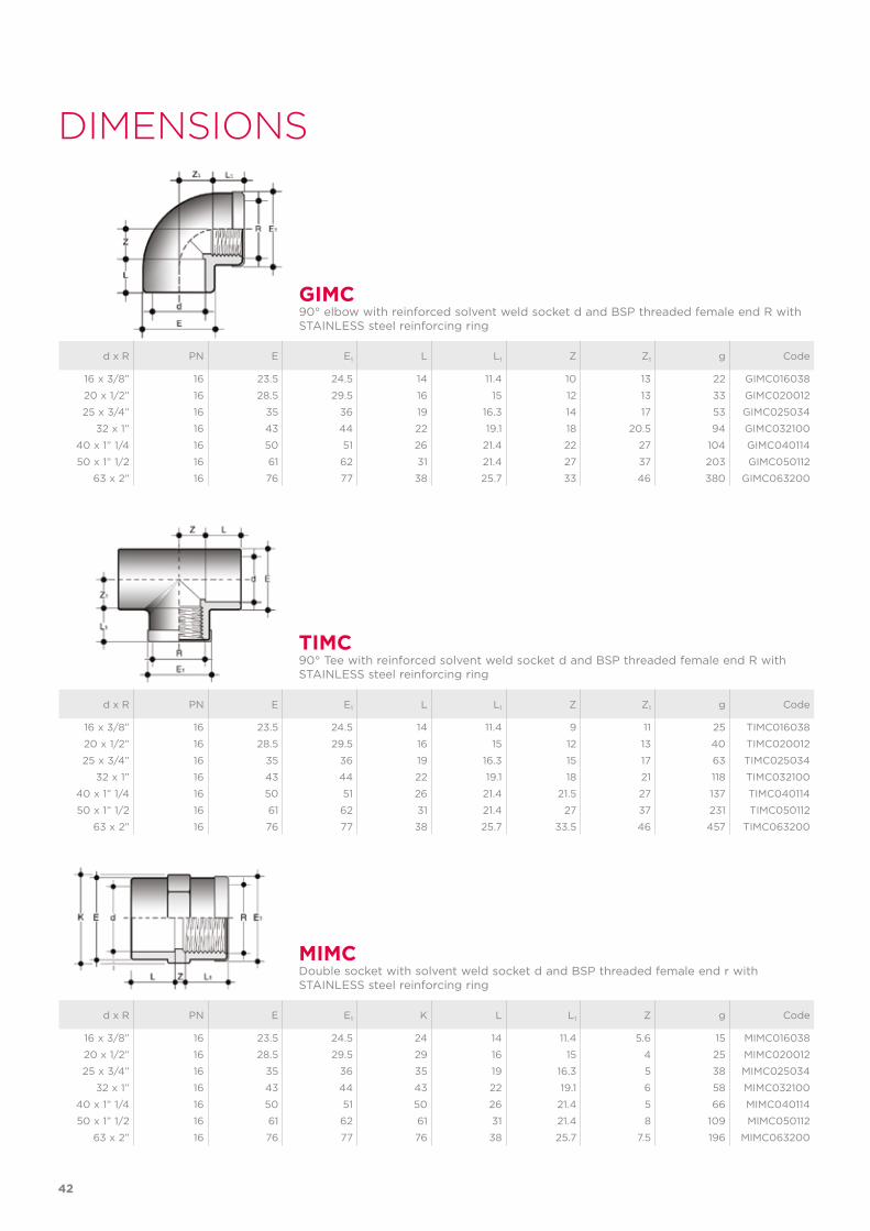
d x R PN E E1 L L1 Z Z1 g Code
16 x 3/8” 16 23.5 24.5 14 11.4 9 11 25 TIMC016038
20 x 1/2” 16 28.5 29.5 16 15 12 13 40 TIMC020012
25 x 3/4” 16 35 36 19 16.3 15 17 63 TIMC025034
32 x 1” 16 43 44 22 19.1 18 21 118 TIMC032100
40 x 1” 1/4 16 50 51 26 21.4 21.5 27 137 TIMC040114
50 x 1” 1/2 16 61 62 31 21.4 27 37 231 TIMC050112
63 x 2” 16 76 77 38 25.7 33.5 46 457 TIMC063200
TIMC90° Tee with reinforced solvent weld socket d and BSP threaded female end R with STAINLESS steel reinforcing ring
d x R PN E E1 L L1 Z Z1 g Code
16 x 3/8” 16 23.5 24.5 14 11.4 10 13 22 GIMC016038
20 x 1/2” 16 28.5 29.5 16 15 12 13 33 GIMC020012
25 x 3/4” 16 35 36 19 16.3 14 17 53 GIMC025034
32 x 1” 16 43 44 22 19.1 18 20.5 94 GIMC032100
40 x 1” 1/4 16 50 51 26 21.4 22 27 104 GIMC040114
50 x 1” 1/2 16 61 62 31 21.4 27 37 203 GIMC050112
63 x 2” 16 76 77 38 25.7 33 46 380 GIMC063200
GIMC90° elbow with reinforced solvent weld socket d and BSP threaded female end R with STAINLESS steel reinforcing ring
d x R PN E E1 K L L1 Z g Code
16 x 3/8” 16 23.5 24.5 24 14 11.4 5.6 15 MIMC016038
20 x 1/2” 16 28.5 29.5 29 16 15 4 25 MIMC020012
25 x 3/4” 16 35 36 35 19 16.3 5 38 MIMC025034
32 x 1” 16 43 44 43 22 19.1 6 58 MIMC032100
40 x 1” 1/4 16 50 51 50 26 21.4 5 66 MIMC040114
50 x 1” 1/2 16 61 62 61 31 21.4 8 109 MIMC050112
63 x 2” 16 76 77 76 38 25.7 7.5 196 MIMC063200
MIMCDouble socket with solvent weld socket d and BSP threaded female end r with STAINLESS steel reinforcing ring
DIMENSIONS
43
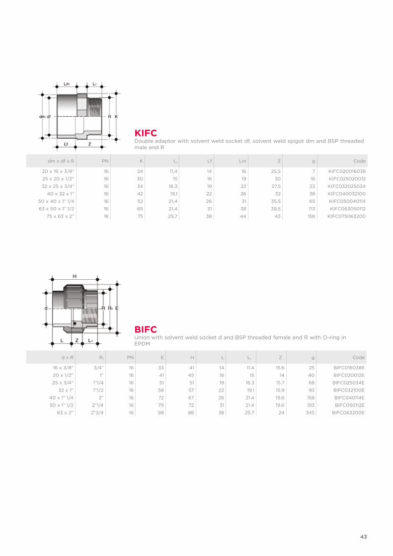
dm x df x R PN K L1 Lf Lm Z g Code
20 x 16 x 3/8” 16 24 11,4 14 16 25,5 7 KIFC020016038
25 x 20 x 1/2” 16 30 15 16 19 30 16 KIFC025020012
32 x 25 x 3/4” 16 34 16,3 19 22 27,5 23 KIFC032025034
40 x 32 x 1” 16 42 19,1 22 26 32 38 KIFC040032100
50 x 40 x 1” 1/4 16 52 21,4 26 31 35,5 65 KIFC050040114
63 x 50 x 1” 1/2 16 65 21,4 31 38 39,5 113 KIFC063050112
75 x 63 x 2” 16 75 25,7 38 44 43 158 KIFC075063200
KIFCDouble adaptor with solvent weld socket df, solvent weld spigot dm and BSP threaded male end R
d x R R1 PN E H L L1 Z g Code
16 x 3/8” 3/4” 16 33 41 14 11.4 15.6 25 BIFC016038E
20 x 1/2” 1” 16 41 45 16 15 14 40 BIFC020012E
25 x 3/4” 1”1/4 16 51 51 19 16.3 15.7 68 BIFC025034E
32 x 1” 1”1/2 16 58 57 22 19.1 15.9 93 BIFC032100E
40 x 1” 1/4 2” 16 72 67 26 21.4 19.6 158 BIFC040114E
50 x 1” 1/2 2”1/4 16 79 72 31 21.4 19.6 193 BIFC050112E
63 x 2” 2”3/4 16 98 88 38 25.7 24 345 BIFC063200E
BIFCUnion with solvent weld socket d and BSP threaded female end R with O-ring in EPDM
44
d x R R1 PN E H K L L1 Z g Code
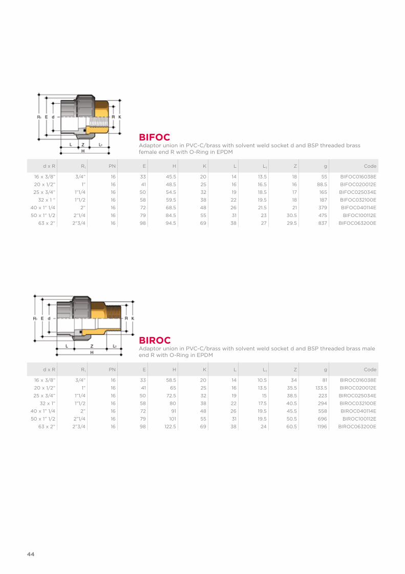
16 x 3/8” 3/4” 16 33 45.5 20 14 13.5 18 55 BIFOC016038E
20 x 1/2” 1” 16 41 48.5 25 16 16.5 16 88.5 BIFOC020012E
25 x 3/4” 1”1/4 16 50 54.5 32 19 18.5 17 165 BIFOC025034E
32 x 1 “ 1”1/2 16 58 59.5 38 22 19.5 18 187 BIFOC032100E
40 x 1” 1/4 2” 16 72 68.5 48 26 21.5 21 379 BIFOC040114E
50 x 1” 1/2 2”1/4 16 79 84.5 55 31 23 30.5 475 BIFOC100112E
63 x 2” 2”3/4 16 98 94.5 69 38 27 29.5 837 BIFOC063200E
d x R R1 PN E H K L L1 Z g Code
16 x 3/8” 3/4” 16 33 58.5 20 14 10.5 34 81 BIROC016038E
20 x 1/2” 1” 16 41 65 25 16 13.5 35.5 133.5 BIROC020012E
25 x 3/4” 1”1/4 16 50 72.5 32 19 15 38.5 223 BIROC025034E
32 x 1” 1”1/2 16 58 80 38 22 17.5 40.5 294 BIROC032100E
40 x 1” 1/4 2” 16 72 91 48 26 19.5 45.5 558 BIROC040114E
50 x 1” 1/2 2”1/4 16 79 101 55 31 19.5 50.5 696 BIROC100112E
63 x 2” 2”3/4 16 98 122.5 69 38 24 60.5 1196 BIROC063200E
BIFOCAdaptor union in PVC-C/brass with solvent weld socket d and BSP threaded brass female end R with O-Ring in EPDM
BIROCAdaptor union in PVC-C/brass with solvent weld socket d and BSP threaded brass male end R with O-Ring in EPDM
45
d x R R1 PN E H K L L1 Z g EPDM Code FPM Code
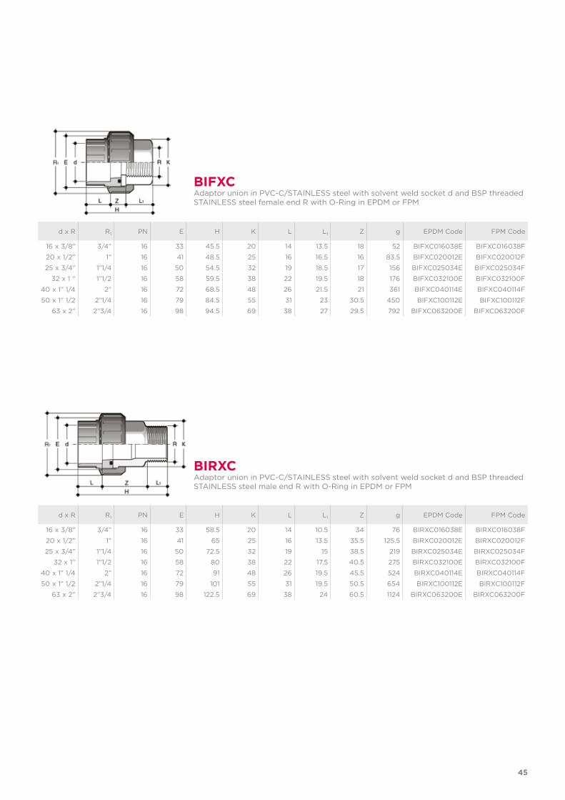
16 x 3/8” 3/4” 16 33 45.5 20 14 13.5 18 52 BIFXC016038E BIFXC016038F
20 x 1/2” 1” 16 41 48.5 25 16 16.5 16 83.5 BIFXC020012E BIFXC020012F
25 x 3/4” 1”1/4 16 50 54.5 32 19 18.5 17 156 BIFXC025034E BIFXC025034F
32 x 1 “ 1”1/2 16 58 59.5 38 22 19.5 18 176 BIFXC032100E BIFXC032100F
40 x 1” 1/4 2” 16 72 68.5 48 26 21.5 21 361 BIFXC040114E BIFXC040114F
50 x 1” 1/2 2”1/4 16 79 84.5 55 31 23 30.5 450 BIFXC100112E BIFXC100112F
63 x 2” 2”3/4 16 98 94.5 69 38 27 29.5 792 BIFXC063200E BIFXC063200F
d x R R1 PN E H K L L1 Z g EPDM Code FPM Code
16 x 3/8” 3/4” 16 33 58.5 20 14 10.5 34 76 BIRXC016038E BIRXC016038F
20 x 1/2” 1” 16 41 65 25 16 13.5 35.5 125.5 BIRXC020012E BIRXC020012F
25 x 3/4” 1”1/4 16 50 72.5 32 19 15 38.5 219 BIRXC025034E BIRXC025034F
32 x 1” 1”1/2 16 58 80 38 22 17.5 40.5 275 BIRXC032100E BIRXC032100F
40 x 1” 1/4 2” 16 72 91 48 26 19.5 45.5 524 BIRXC040114E BIRXC040114F
50 x 1” 1/2 2”1/4 16 79 101 55 31 19.5 50.5 654 BIRXC100112E BIRXC100112F
63 x 2” 2”3/4 16 98 122.5 69 38 24 60.5 1124 BIRXC063200E BIRXC063200F
BIFXCAdaptor union in PVC-C/STAINLESS steel with solvent weld socket d and BSP threaded STAINLESS steel female end R with O-Ring in EPDM or FPM
BIRXCAdaptor union in PVC-C/STAINLESS steel with solvent weld socket d and BSP threaded STAINLESS steel male end R with O-Ring in EPDM or FPM
46
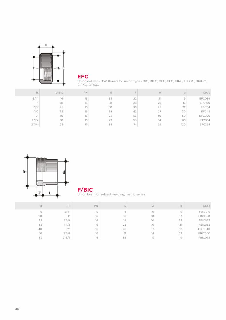
d R1 PN L Z g Code
16 3/4” 16 14 10 9 FBIC016
20 1” 16 16 10 13 FBIC020
25 1”1/4 16 19 10 25 FBIC025
32 1”1/2 16 22 10 31 FBIC032
40 2” 16 26 12 58 FBIC040
50 2”1/4 16 31 14 63 FBIC050
63 2”3/4 16 38 19 119 FBIC063
F/BICUnion bush for solvent welding, metric series
R1 d BIC PN E F H g Code
3/4” 16 16 33 22 21 9 EFC034
1” 20 16 41 28 22 13 EFC100
1”1/4 25 16 50 36 25 22 EFC114
1”1/2 32 16 58 42 27 30 EFC112
2” 40 16 72 53 30 50 EFC200
2”1/4 50 16 79 59 34 68 EFC214
2”3/4 63 16 98 74 38 120 EFC234
EFCUnion nut with BSP thread for union types BIC, BIFC, BFC, BLC, BIRC, BIFOC, BIROC, BIFXC, BIRXC.
47
d PN d3 d4 L Z g Code
1/2” 16 27.5 30.1 22.7 3.5 17 QBAC012
3/4” 16 36 38.8 25.9 3.7 25 QBAC034
1” 16 41.5 44.7 29.2 3 36 QBAC100
1”1/4 16 53 56.5 32 5 63 QBAC114
1”1/2 16 59 62.6 35 5 86 QBAC112
2” 16 74 78.4 38.5 5.5 143 QBAC200
Q/BACUnion end for solvent welding, ASTM series
d PN d3 d4 L Z g Code
16 16 22 24 14 3 5 QBIC016
20 16 27.5 30.1 16 3 10 QBIC020
25 16 36 38.8 19 3 16 QBIC025
32 16 41.5 44.7 22 3 23 QBIC032
40 16 53 56.5 26 3 40 QBIC040
50 16 59 62.6 31 3 44 QBIC050
63 16 74 78.4 38 3 82 QBIC063
Q/BICUnion end for solvent welding, metric series

48
R PN d3 d4 L Z g Code
3/8” 16 22 24 12.7 6.3 11 QBNC038
1/2” 16 27.5 30.1 17.8 5.2 17 QBNC012
3/4” 16 36 38.8 18 5.2 22 QBNC034
1” 16 41.5 44.7 22.6 5.7 33 QBNC100
1”1/4 16 53 56.5 25.1 7.3 61 QBNC114
1”1/2 16 59 62.6 24.7 7 77 QBNC112
2” 16 74 78.4 29.6 7.8 127 QBNC200
Q/BNCUnion end with NPT female thread
R PN d3 d4 L Z g Code
3/8” 16 22 24 11.4 4.5 5 QBFC038
1/2” 16 27.5 30.1 15 5 9 QBFC012
3/4” 16 36 38.8 16.3 5 17 QBFC034
1” 16 41.5 44.7 19.1 5.5 23 QBFC100
1”1/4 16 53 56.5 21.4 5.5 37 QBFC114
1”1/2 16 59 62.6 21.4 5.5 44 QBFC112
2” 16 74 78.4 25.7 5.5 79 QBFC200
Q/BFCUnion end with BSP female thread
R d3 d4 H L1 g Code
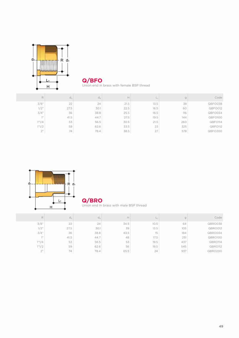
3/8” 22 24 21.5 13.5 38 QBFO038
1/2” 27.5 30.1 22.5 16.5 60 QBFO012
3/4” 36 38.8 25.5 18.5 116 QBFO034
1” 41.5 44.7 27.5 19.5 144 QBFO100
1”1/4 53 56.5 30.5 21.5 260 QBFO114
1”1/2 59 62.6 33.5 23 325 QBFO112
2” 74 78.4 38.5 27 578 QBFO200
Q/BFOUnion end in brass with female BSP thread
R d3 d4 H L1 g Code
3/8” 22 24 34.5 10.5 64 QBRO038
1/2” 27.5 30.1 39 13.5 105 QBRO012
3/4” 36 38.8 43.5 15 184 QBRO034
1” 41.5 44.7 48 17.5 251 QBRO100
1”1/4 53 56.5 53 19.5 437 QBRO114
1”1/2 59 62.6 56 19.5 545 QBRO112
2” 74 78.4 65.5 24 937 QBRO200
Q/BROUnion end in brass with male BSP thread
49
R d3 d4 H L1 g Code
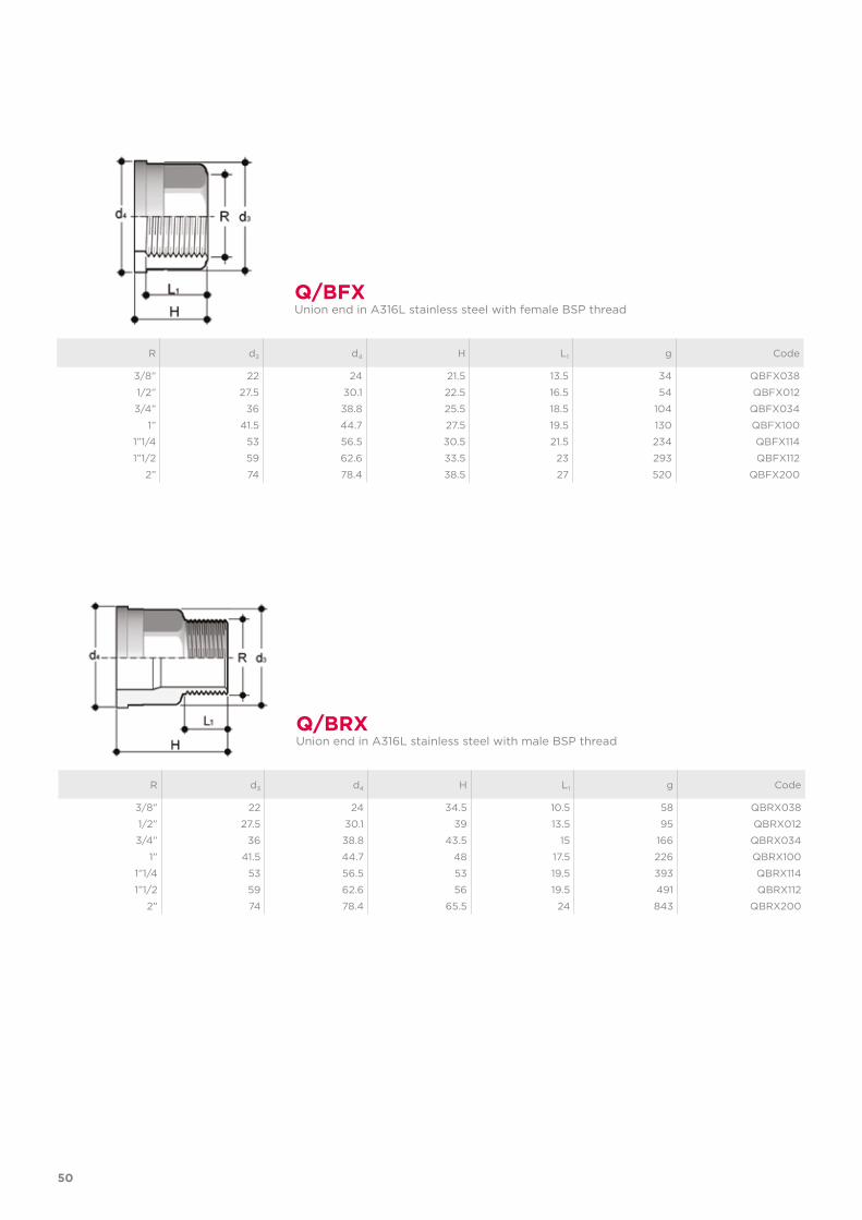
3/8” 22 24 21.5 13.5 34 QBFX038
1/2” 27.5 30.1 22.5 16.5 54 QBFX012
3/4” 36 38.8 25.5 18.5 104 QBFX034
1” 41.5 44.7 27.5 19.5 130 QBFX100
1”1/4 53 56.5 30.5 21.5 234 QBFX114
1”1/2 59 62.6 33.5 23 293 QBFX112
2” 74 78.4 38.5 27 520 QBFX200
Q/BFXUnion end in A316L stainless steel with female BSP thread
R d3 d4 H L1 g Code
3/8” 22 24 34.5 10.5 58 QBRX038
1/2” 27.5 30.1 39 13.5 95 QBRX012
3/4” 36 38.8 43.5 15 166 QBRX034
1” 41.5 44.7 48 17.5 226 QBRX100
1”1/4 53 56.5 53 19.5 393 QBRX114
1”1/2 59 62.6 56 19.5 491 QBRX112
2” 74 78.4 65.5 24 843 QBRX200
Q/BRXUnion end in A316L stainless steel with male BSP thread
50
Union d C di T EPDM Code FPM Code
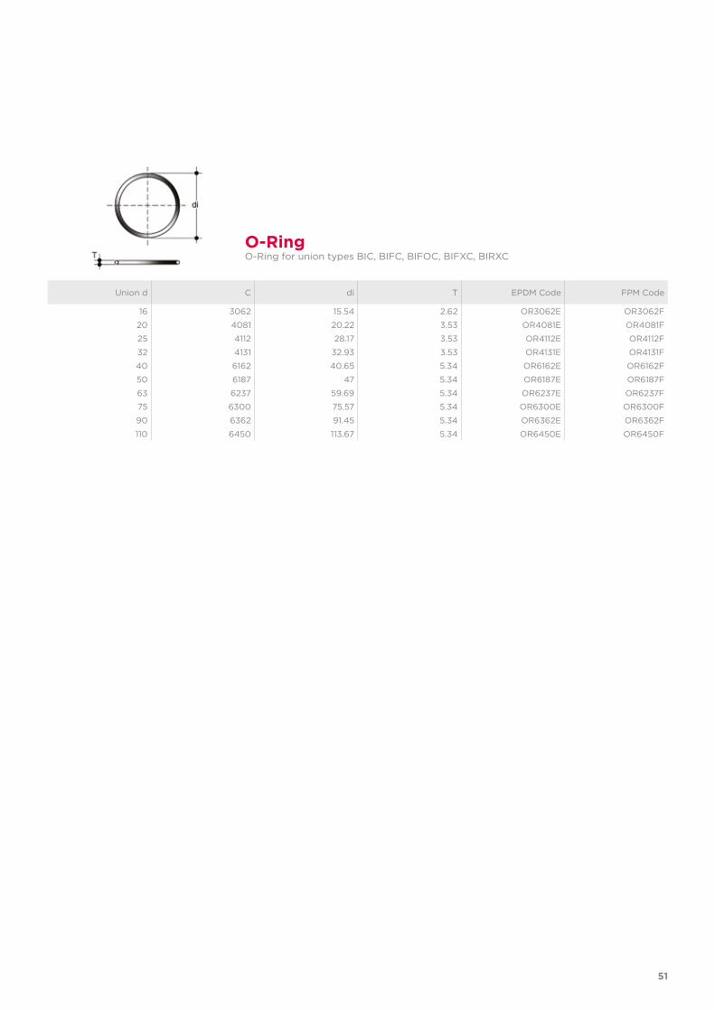
16 3062 15.54 2.62 OR3062E OR3062F
20 4081 20.22 3.53 OR4081E OR4081F
25 4112 28.17 3.53 OR4112E OR4112F
32 4131 32.93 3.53 OR4131E OR4131F
40 6162 40.65 5.34 OR6162E OR6162F
50 6187 47 5.34 OR6187E OR6187F
63 6237 59.69 5.34 OR6237E OR6237F
75 6300 75.57 5.34 OR6300E OR6300F
90 6362 91.45 5.34 OR6362E OR6362F
110 6450 113.67 5.34 OR6450E OR6450F
O-RingO-Ring for union types BIC, BIFC, BIFOC, BIFXC, BIRXC
51

VKD DN 10÷50PVC-C
DUAL BLOCK® 2-way ball valve
54
Technical specificationsConstruction 2-way True union ball valve
with locked carrier and lockable union nutsSize range DN 10 ÷ 50Nominal pressure PN 16 with water at 20° CTemperature range 0 °C ÷ 100 °CCoupling standards Solvent welding: EN ISO 15493, ASTM F 439. Can be
coupled to pipes according to EN ISO 15493, ASTM F 441Thread: ISO 228-1, DIN 2999, ASTM F437Flanging system: ISO 7005-1, EN ISO 15493, EN 558-1,DIN 2501, ANSI B.16.5 cl. 150, JIS B 2220
Reference standards Construction criteria: EN ISO 16135, EN ISO 15493Test methods and requirements: ISO 9393Installation criteria: DVS 2204, DVS 2221, UNI 11242Actuator couplings: ISO 5211
Valve material PVC-CSeal material EPDM, FPM (standard size O-Ring);
PTFE (ball seats)
Control options Manual control; electric actuator; pneumatic actuator
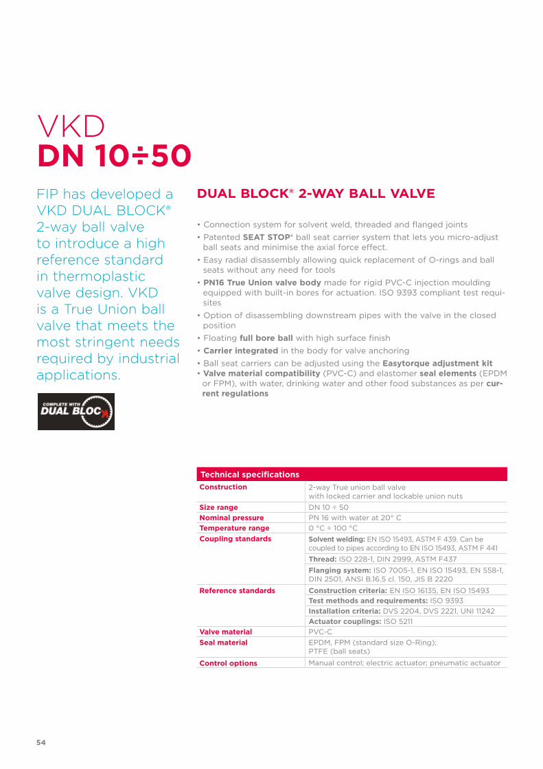
VKD
FIP has developed aVKD DUAL BLOCK®2-way ball valveto introduce a highreference standard in thermoplastic valve design. VKD is a True Union ball valve that meets the most stringent needs required by industrial applications.
DUAL BLOCK® 2-WAY BALL VALVE
DN 10÷50
• Connection system for solvent weld, threaded and flanged joints• Patented SEAT STOP® ball seat carrier system that lets you micro-adjust
ball seats and minimise the axial force effect.• Easy radial disassembly allowing quick replacement of O-rings and ball
seats without any need for tools• PN16 True Union valve body made for rigid PVC-C injection moulding
equipped with built-in bores for actuation. ISO 9393 compliant test requi-sites
• Option of disassembling downstream pipes with the valve in the closed position
• Floating full bore ball with high surface finish• Carrier integrated in the body for valve anchoring• Ball seat carriers can be adjusted using the Easytorque adjustment kit• Valve material compatibility (PVC-C) and elastomer seal elements (EPDM
or FPM), with water, drinking water and other food substances as per cur-rent regulations
55
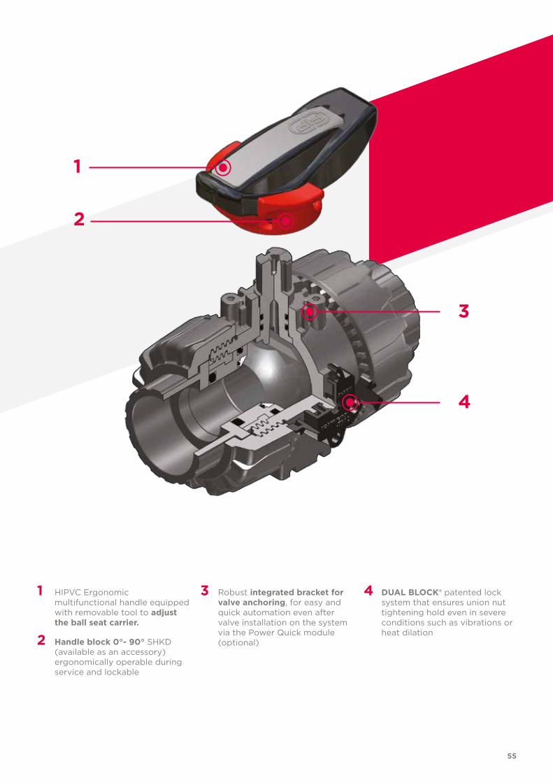
1 HIPVC Ergonomic multifunctional handle equipped with removable tool to adjust the ball seat carrier.
2 Handle block 0°- 90° SHKD (available as an accessory) ergonomically operable during service and lockable
3 Robust integrated bracket for valve anchoring, for easy and quick automation even after valve installation on the system via the Power Quick module (optional)
4 DUAL BLOCK® patented lock system that ensures union nut tightening hold even in severe conditions such as vibrations or heat dilation
1
2
3
4
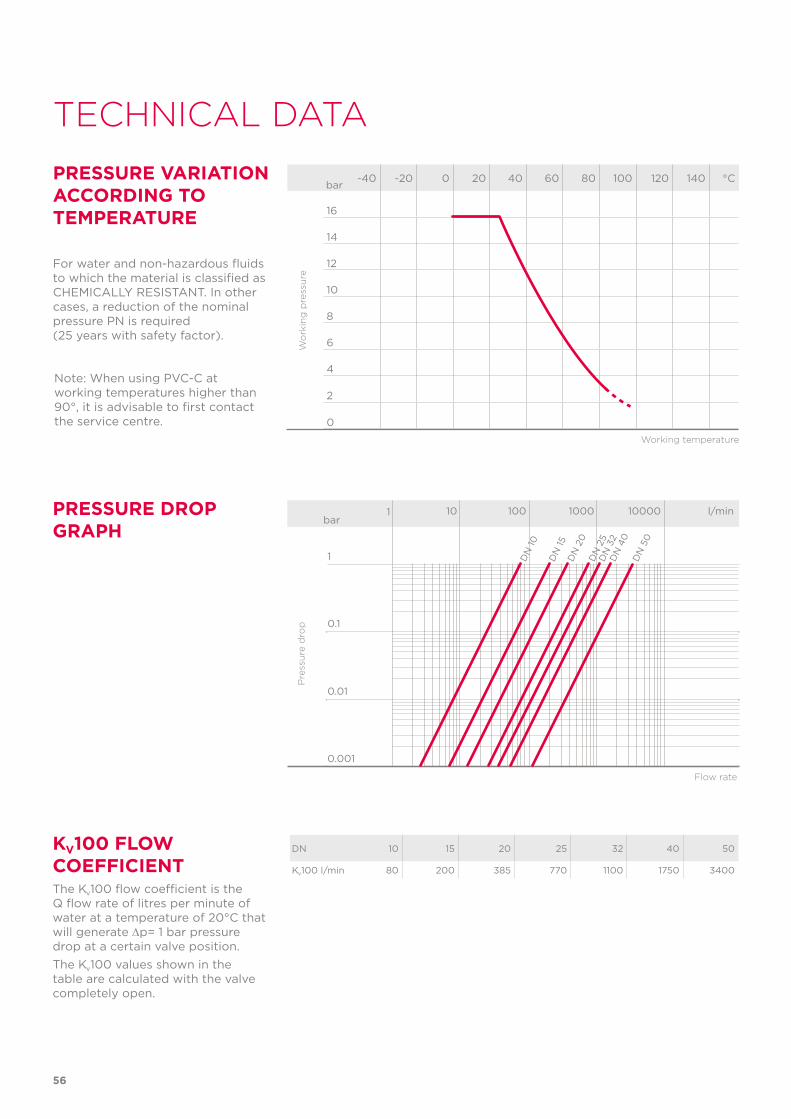
PRESSURE DROP GRAPH
Pre
ssu
re d
rop
Flow rate
bar1 10 100 1000 10000 l/min
1
0.1
0.01
0.001
DN
15
DN
10
DN
20
DN
25
DN
32
DN
40
DN
50
56
TECHNICAL DATA
-40 -20 0 20 40 60 80 100 120 140 °C
16
14
12
10
8
6
4
2
0
Wo
rkin
g p
ress
ure
Working temperature
barPRESSURE VARIATION ACCORDING TO TEMPERATURE
For water and non-hazardous fluids to which the material is classified as CHEMICALLY RESISTANT. In other cases, a reduction of the nominal pressure PN is required (25 years with safety factor).
KV100 FLOW COEFFICIENTThe Kv100 flow coefficient is the Q flow rate of litres per minute of water at a temperature of 20°C that will generate ∆p= 1 bar pressure drop at a certain valve position.The Kv100 values shown in the table are calculated with the valve completely open.
DN 10 15 20 25 32 40 50
Kv100 l/min 80 200 385 770 1100 1750 3400
Note: When using PVC-C at working temperatures higher than 90°, it is advisable to first contact the service centre.
57
The information in this leaflet is provided in good faith. No liability will be accepted concerning technical data that is not directly covered by recognised international standards. FIP reserves the right to carry out any modification. Products must be installed and maintained by qualified personnel.
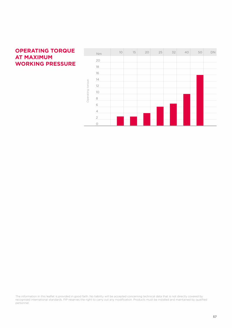
OPERATING TORQUE AT MAXIMUM WORKING PRESSURE
Nm 10 15 20 25 32 40 50 DN
20
18
16
14
12
10
8
6
4
2
0
Op
erat
ing
to
rqu
e
d DN PN B B1 C C1 E H H1 L g EPDM Code FPM Code
20 15 16 54 29 67 40 54 124 65 16 239 VKDDC020E VKDDC020F
25 20 16 65 34.5 85 49 65 144 70 19 369 VKDDC025E VKDDC025F
32 25 16 69.5 39 85 49 73 154 78 22 482 VKDDC032E VKDDC032F
40 32 16 82.5 46 108 64 86 174 88 26 753 VKDDC040E VKDDC040F
50 40 16 89 52 108 64 98 194 93 31 1029 VKDDC050E VKDDC050F
63 50 16 108 62 134 76 122 224 111 38 1749 VKDDC063E VKDDC063F
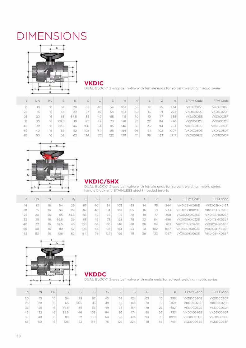
VKDDCDUAL BLOCK® 2-way ball valve with male ends for solvent welding, metric series
d DN PN B B1 C C1 E H H1 L Z g EPDM Code FPM Code
16 10 16 54 29 67 40 54 103 65 14 75 234 VKDIC016E VKDIC016F
20 15 16 54 29 67 40 54 103 65 16 71 223 VKDIC020E VKDIC020F
25 20 16 65 34.5 85 49 65 115 70 19 77 358 VKDIC025E VKDIC025F
32 25 16 69.5 39 85 49 73 128 78 22 84 476 VKDIC032E VKDIC032F
40 32 16 82.5 46 108 64 86 146 88 26 94 753 VKDIC040E VKDIC040F
50 40 16 89 52 108 64 98 164 93 31 102 1007 VKDIC050E VKDIC050F
63 50 16 108 62 134 76 122 199 111 38 123 1717 VKDIC063E VKDIC063F
d DN PN B B1 C C1 E H H1 L Z g EPDM Code FPM Code
16 10 16 54 29 67 40 54 103 65 14 75 244 VKDICSHX016E VKDICSHX016F
20 15 16 54 29 67 40 54 103 65 16 71 233 VKDICSHX020E VKDICSHX020F
25 20 16 65 34.5 85 49 65 115 70 19 77 368 VKDICSHX025E VKDICSHX025F
32 25 16 69.5 39 85 49 73 128 78 22 84 486 VKDICSHX032E VKDICSHX032F
40 32 16 82.5 46 108 64 86 146 88 26 94 763 VKDICSHX040E VKDICSHX040F
50 40 16 89 52 108 64 98 164 93 31 102 1017 VKDICSHX050E VKDICSHX050F
63 50 16 108 62 134 76 122 199 111 38 123 1727 VKDICSHX063E VKDICSHX063F
VKDIC
VKDIC/SHX
DUAL BLOCK® 2-way ball valve with female ends for solvent welding, metric series
DUAL BLOCK® 2-way ball valve with female ends for solvent welding, metric series, handle block and STAINLESS steel threaded inserts
58
DIMENSIONS
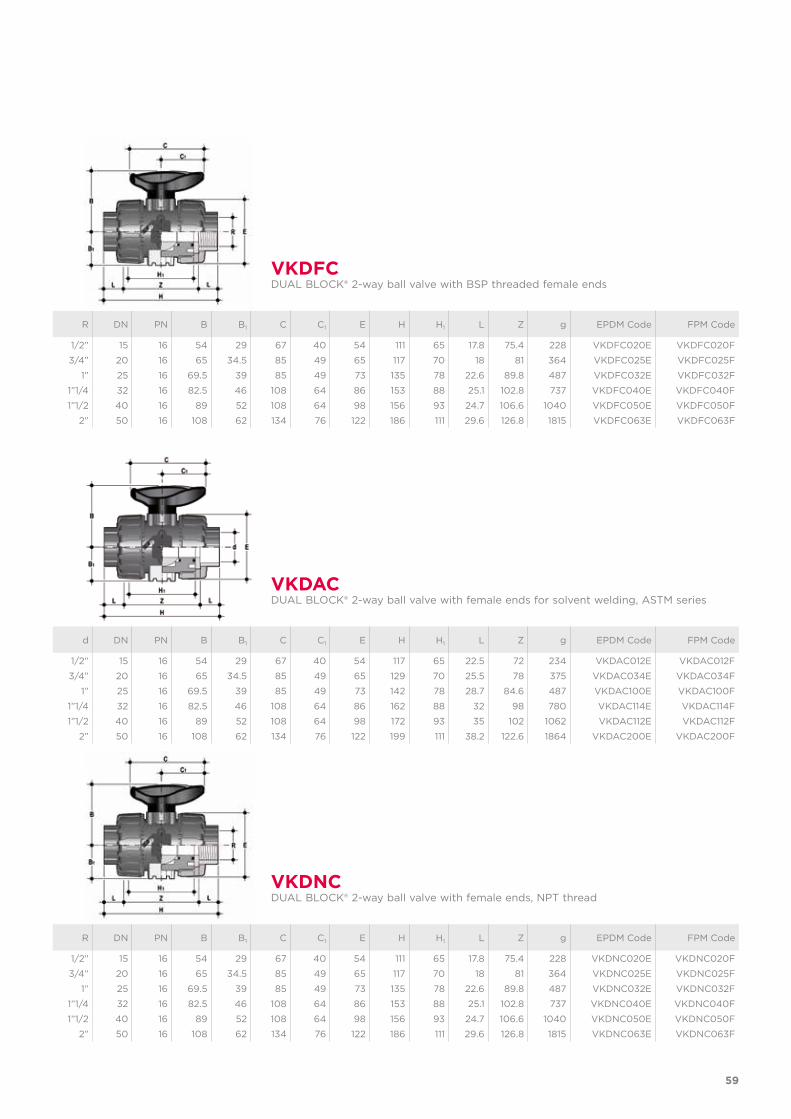
R DN PN B B1 C C1 E H H1 L Z g EPDM Code FPM Code
1/2” 15 16 54 29 67 40 54 111 65 17.8 75.4 228 VKDNC020E VKDNC020F
3/4” 20 16 65 34.5 85 49 65 117 70 18 81 364 VKDNC025E VKDNC025F
1” 25 16 69.5 39 85 49 73 135 78 22.6 89.8 487 VKDNC032E VKDNC032F
1”1/4 32 16 82.5 46 108 64 86 153 88 25.1 102.8 737 VKDNC040E VKDNC040F
1”1/2 40 16 89 52 108 64 98 156 93 24.7 106.6 1040 VKDNC050E VKDNC050F
2” 50 16 108 62 134 76 122 186 111 29.6 126.8 1815 VKDNC063E VKDNC063F
VKDNCDUAL BLOCK® 2-way ball valve with female ends, NPT thread
R DN PN B B1 C C1 E H H1 L Z g EPDM Code FPM Code
1/2” 15 16 54 29 67 40 54 111 65 17.8 75.4 228 VKDFC020E VKDFC020F
3/4” 20 16 65 34.5 85 49 65 117 70 18 81 364 VKDFC025E VKDFC025F
1” 25 16 69.5 39 85 49 73 135 78 22.6 89.8 487 VKDFC032E VKDFC032F
1”1/4 32 16 82.5 46 108 64 86 153 88 25.1 102.8 737 VKDFC040E VKDFC040F
1”1/2 40 16 89 52 108 64 98 156 93 24.7 106.6 1040 VKDFC050E VKDFC050F
2” 50 16 108 62 134 76 122 186 111 29.6 126.8 1815 VKDFC063E VKDFC063F
d DN PN B B1 C C1 E H H1 L Z g EPDM Code FPM Code
1/2” 15 16 54 29 67 40 54 117 65 22.5 72 234 VKDAC012E VKDAC012F
3/4” 20 16 65 34.5 85 49 65 129 70 25.5 78 375 VKDAC034E VKDAC034F
1” 25 16 69.5 39 85 49 73 142 78 28.7 84.6 487 VKDAC100E VKDAC100F
1”1/4 32 16 82.5 46 108 64 86 162 88 32 98 780 VKDAC114E VKDAC114F
1”1/2 40 16 89 52 108 64 98 172 93 35 102 1062 VKDAC112E VKDAC112F
2” 50 16 108 62 134 76 122 199 111 38.2 122.6 1864 VKDAC200E VKDAC200F
VKDFC
VKDAC
DUAL BLOCK® 2-way ball valve with BSP threaded female ends
DUAL BLOCK® 2-way ball valve with female ends for solvent welding, ASTM series
59
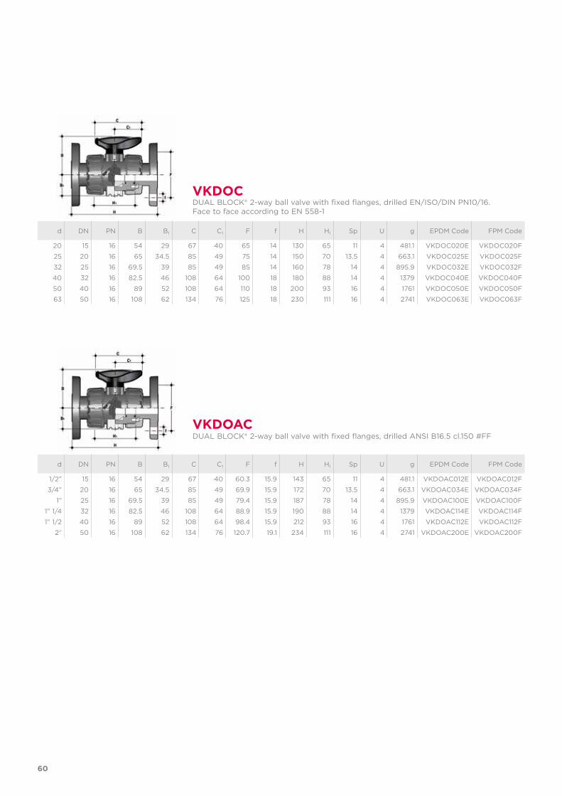
d DN PN B B1 C C1 F f H H1 Sp U g EPDM Code FPM Code
20 15 16 54 29 67 40 65 14 130 65 11 4 481.1 VKDOC020E VKDOC020F
25 20 16 65 34.5 85 49 75 14 150 70 13.5 4 663.1 VKDOC025E VKDOC025F
32 25 16 69.5 39 85 49 85 14 160 78 14 4 895.9 VKDOC032E VKDOC032F
40 32 16 82.5 46 108 64 100 18 180 88 14 4 1379 VKDOC040E VKDOC040F
50 40 16 89 52 108 64 110 18 200 93 16 4 1761 VKDOC050E VKDOC050F
63 50 16 108 62 134 76 125 18 230 111 16 4 2741 VKDOC063E VKDOC063F
d DN PN B B1 C C1 F f H H1 Sp U g EPDM Code FPM Code
1/2” 15 16 54 29 67 40 60.3 15.9 143 65 11 4 481.1 VKDOAC012E VKDOAC012F
3/4” 20 16 65 34.5 85 49 69.9 15.9 172 70 13.5 4 663.1 VKDOAC034E VKDOAC034F
1” 25 16 69.5 39 85 49 79.4 15.9 187 78 14 4 895.9 VKDOAC100E VKDOAC100F
1” 1/4 32 16 82.5 46 108 64 88.9 15.9 190 88 14 4 1379 VKDOAC114E VKDOAC114F
1” 1/2 40 16 89 52 108 64 98.4 15.9 212 93 16 4 1761 VKDOAC112E VKDOAC112F
2” 50 16 108 62 134 76 120.7 19.1 234 111 16 4 2741 VKDOAC200E VKDOAC200F
VKDOC
VKDOAC
DUAL BLOCK® 2-way ball valve with fixed flanges, drilled EN/ISO/DIN PN10/16.Face to face according to EN 558-1
DUAL BLOCK® 2-way ball valve with fixed flanges, drilled ANSI B16.5 cl.150 #FF
60
ACCESSORIES
d DN Code
16 - 20 10 - 15 SHKD020
25 - 32 20 - 25 SHKD032
40 - 50 32 - 40 SHKD050
63 50 SHKD063
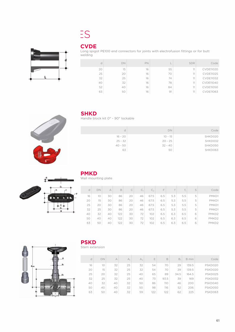
SHKDHandle block kit 0° - 90° lockable
d DN A A1 A2 E B B1 B min Code
16 10 32 25 32 54 70 29 139.5 PSKD020
20 15 32 25 32 54 70 29 139.5 PSKD020
25 20 32 25 40 65 89 34.5 164.5 PSKD025
32 25 32 25 40 73 93.5 39 169 PSKD032
40 32 40 32 50 86 110 46 200 PSKD040
50 40 40 32 50 98 116 52 206 PSKD050
63 50 40 32 59 122 122 62 225 PSKD063
PSKDStem extension
PMKD
d DN A B C C1 C2 F f f1 S Code
16 10 30 86 20 46 67.5 6.5 5.3 5.5 5 PMKD1
20 15 30 86 20 46 67.5 6.5 5.3 5.5 5 PMKD1
25 20 30 86 20 46 67.5 6.5 5.3 5.5 5 PMKD1
32 25 30 86 20 46 67.5 6.5 5.3 5.5 5 PMKD1
40 32 40 122 30 72 102 6.5 6.3 6.5 6 PMKD2
50 40 40 122 30 72 102 6.5 6.3 6.5 6 PMKD2
63 50 40 122 30 72 102 6.5 6.3 6.5 6 PMKD2
Wall mounting plate
61
d DN PN L SDR Code
20 15 16 55 11 CVDE11020
25 20 16 70 11 CVDE11025
32 25 16 74 11 CVDE11032
40 32 16 78 11 CVDE11040
52 40 16 84 11 CVDE11050
63 50 16 91 11 CVDE11063
CVDELong spigot PE100 end connectors for joints with electrofusion fittings or for butt welding
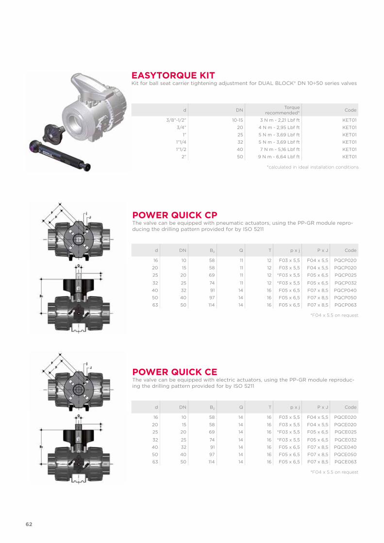
POWER QUICK CPThe valve can be equipped with pneumatic actuators, using the PP-GR module repro-ducing the drilling pattern provided for by ISO 5211
d DN B2 Q T p x j P x J Code
16 10 58 11 12 F03 x 5,5 F04 x 5,5 PQCP020
20 15 58 11 12 F03 x 5,5 F04 x 5,5 PQCP020
25 20 69 11 12 *F03 x 5,5 F05 x 6,5 PQCP025
32 25 74 11 12 *F03 x 5,5 F05 x 6,5 PQCP032
40 32 91 14 16 F05 x 6,5 F07 x 8,5 PQCP040
50 40 97 14 16 F05 x 6,5 F07 x 8,5 PQCP050
63 50 114 14 16 F05 x 6,5 F07 x 8,5 PQCP063
*F04 x 5.5 on request
POWER QUICK CEThe valve can be equipped with electric actuators, using the PP-GR module reproduc-ing the drilling pattern provided for by ISO 5211
d DN B2 Q T p x j P x J Code
16 10 58 14 16 F03 x 5,5 F04 x 5,5 PQCE020
20 15 58 14 16 F03 x 5,5 F04 x 5,5 PQCE020
25 20 69 14 16 *F03 x 5,5 F05 x 6,5 PQCE025
32 25 74 14 16 *F03 x 5,5 F05 x 6,5 PQCE032
40 32 91 14 16 F05 x 6,5 F07 x 8,5 PQCE040
50 40 97 14 16 F05 x 6,5 F07 x 8,5 PQCE050
63 50 114 14 16 F05 x 6,5 F07 x 8,5 PQCE063
*F04 x 5.5 on request
EASYTORQUE KITKit for ball seat carrier tightening adjustment for DUAL BLOCK® DN 10÷50 series valves
d DN Torque recommended* Code
3/8”-1/2” 10-15 3 N m - 2,21 Lbf ft KET01
3/4” 20 4 N m - 2,95 Lbf ft KET01
1” 25 5 N m - 3,69 Lbf ft KET01
1”1/4 32 5 N m - 3,69 Lbf ft KET01
1”1/2 40 7 N m - 5,16 Lbf ft KET01
2” 50 9 N m - 6,64 Lbf ft KET01
*calculated in ideal installation conditions
62
FASTENING AND SUPPORTING
d DN B H L J*
16 10 31.5 27 20 M4 x 6
20 15 31.5 27 20 M4 x 6
25 20 40 30 20 M4 x 6
32 25 40 30 20 M4 x 6
40 32 50 35 20 M6 x 10
50 40 50 35 20 M6 x 10
63 50 60 40 20 M6 x 10
* With threaded inserts
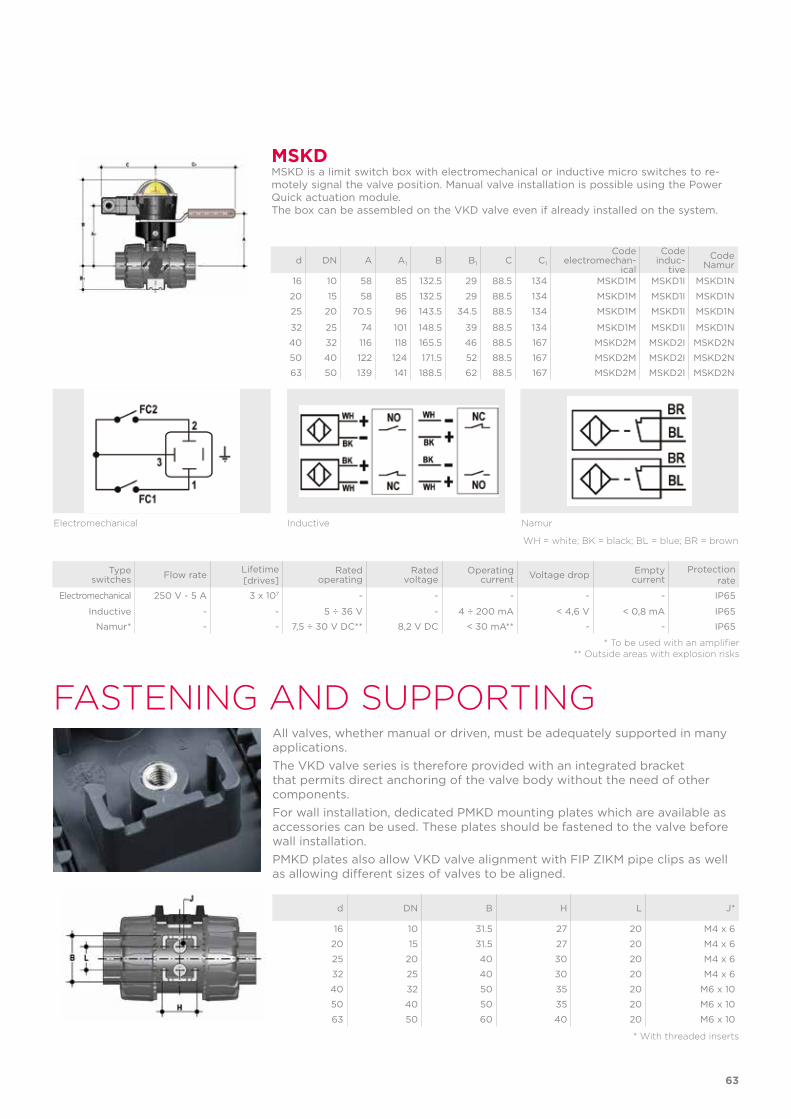
All valves, whether manual or driven, must be adequately supported in many applications. The VKD valve series is therefore provided with an integrated bracket that permits direct anchoring of the valve body without the need of other components.For wall installation, dedicated PMKD mounting plates which are available as accessories can be used. These plates should be fastened to the valve before wall installation. PMKD plates also allow VKD valve alignment with FIP ZIKM pipe clips as well as allowing different sizes of valves to be aligned.
Type switches Flow rate Lifetime
[drives]Rated
operatingRated
voltageOperating
current Voltage drop Empty current
Protection rate
Electromechanical 250 V - 5 A 3 x 10⁷ - - - - - IP65
Inductive - - 5 ÷ 36 V - 4 ÷ 200 mA < 4,6 V < 0,8 mA IP65
Namur* - - 7,5 ÷ 30 V DC** 8,2 V DC < 30 mA** - - IP65
* To be used with an amplifier** Outside areas with explosion risks
Electromechanical Inductive Namur
WH = white; BK = black; BL = blue; BR = brown
MSKDMSKD is a limit switch box with electromechanical or inductive micro switches to re-motely signal the valve position. Manual valve installation is possible using the Power Quick actuation module.The box can be assembled on the VKD valve even if already installed on the system.
d DN A A1 B B1 C C1
Codeelectromechan-
ical
Codeinduc-
tiveCode
Namur
16 10 58 85 132.5 29 88.5 134 MSKD1M MSKD1I MSKD1N
20 15 58 85 132.5 29 88.5 134 MSKD1M MSKD1I MSKD1N
25 20 70.5 96 143.5 34.5 88.5 134 MSKD1M MSKD1I MSKD1N
32 25 74 101 148.5 39 88.5 134 MSKD1M MSKD1I MSKD1N
40 32 116 118 165.5 46 88.5 167 MSKD2M MSKD2I MSKD2N
50 40 122 124 171.5 52 88.5 167 MSKD2M MSKD2I MSKD2N
63 50 139 141 188.5 62 88.5 167 MSKD2M MSKD2I MSKD2N
63
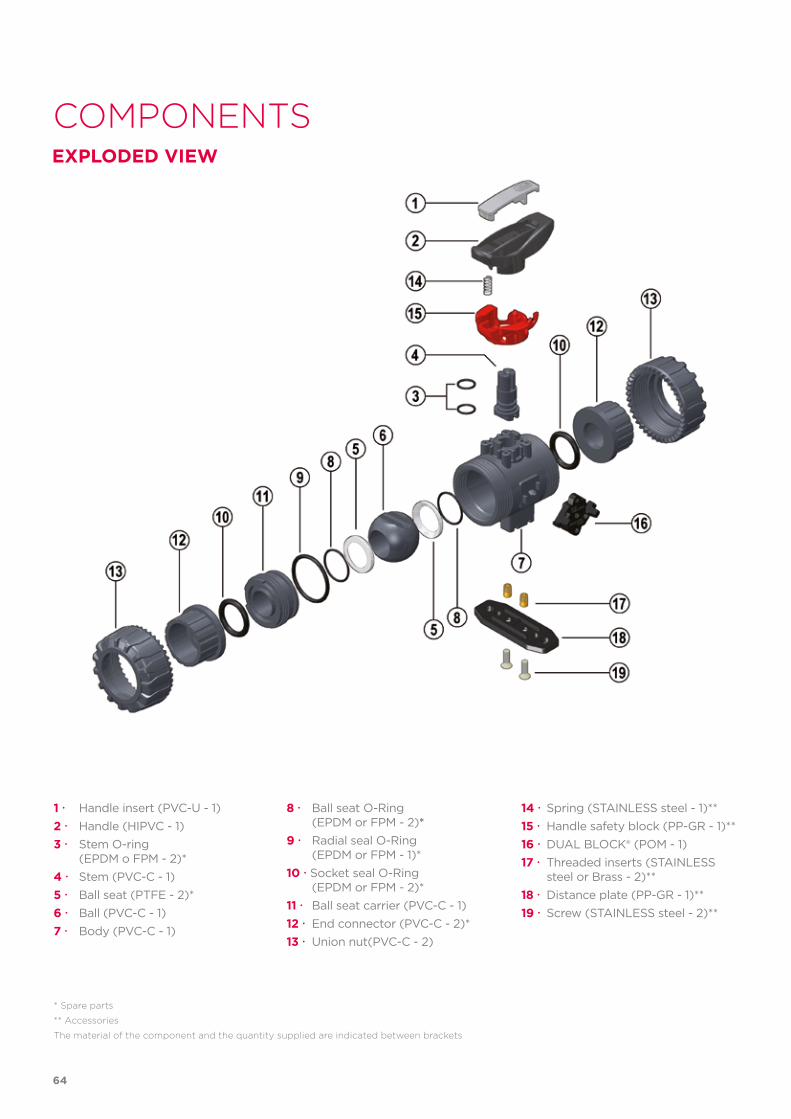
COMPONENTSEXPLODED VIEW
1 Handle insert (PVC-U - 1)2 Handle (HIPVC - 1)3 Stem O-ring (EPDM o FPM - 2)*4 Stem (PVC-C - 1)5 Ball seat (PTFE - 2)*6 Ball (PVC-C - 1)7 Body (PVC-C - 1)
* Spare parts
** Accessories
The material of the component and the quantity supplied are indicated between brackets
8 Ball seat O-Ring (EPDM or FPM - 2)*9 Radial seal O-Ring (EPDM or FPM - 1)*10 Socket seal O-Ring (EPDM or FPM - 2)*11 Ball seat carrier (PVC-C - 1)12 End connector (PVC-C - 2)*13 Union nut(PVC-C - 2)
14 Spring (STAINLESS steel - 1)**15 Handle safety block (PP-GR - 1)**16 DUAL BLOCK® (POM - 1)17 Threaded inserts (STAINLESS steel or Brass - 2)**18 Distance plate (PP-GR - 1)**19 Screw (STAINLESS steel - 2)**
64
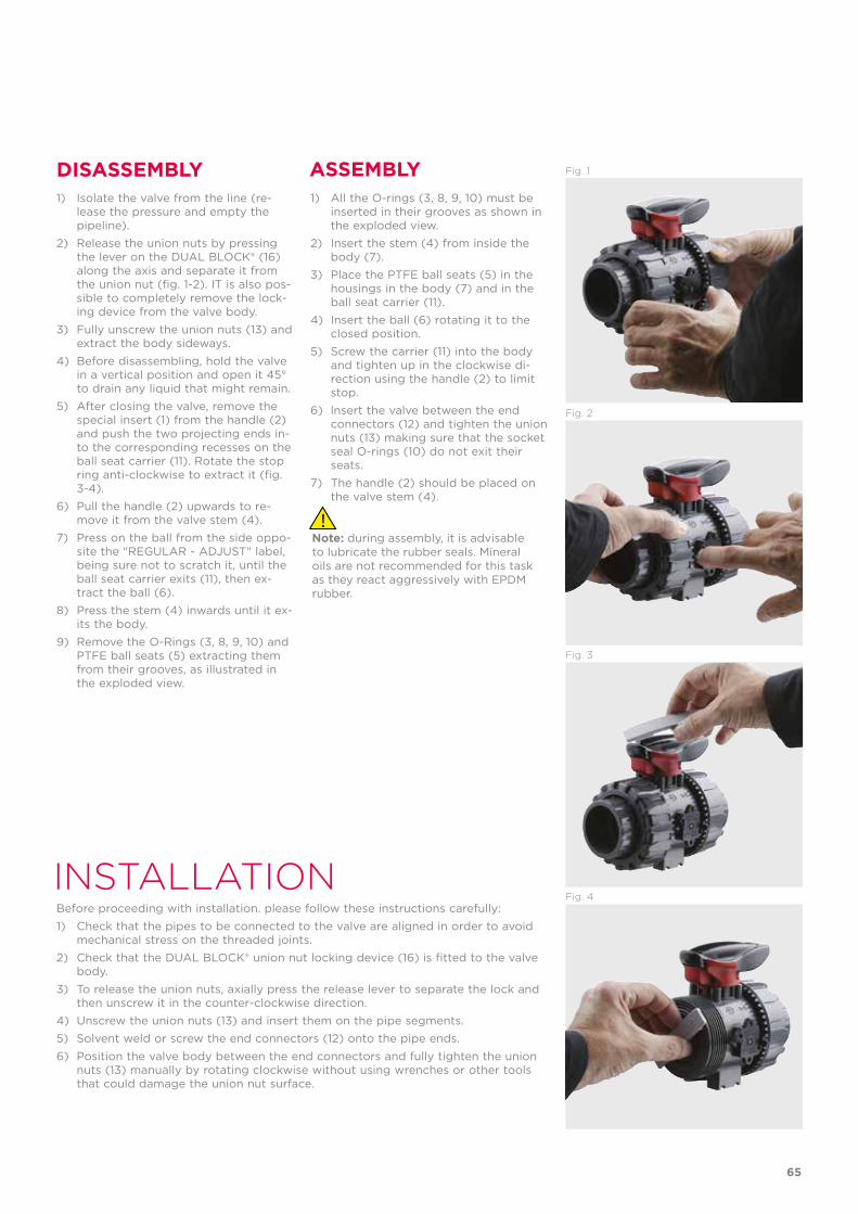
INSTALLATIONBefore proceeding with installation. please follow these instructions carefully:1) Check that the pipes to be connected to the valve are aligned in order to avoid
mechanical stress on the threaded joints.2) Check that the DUAL BLOCK® union nut locking device (16) is fitted to the valve
body.3) To release the union nuts, axially press the release lever to separate the lock and
then unscrew it in the counter-clockwise direction.4) Unscrew the union nuts (13) and insert them on the pipe segments.5) Solvent weld or screw the end connectors (12) onto the pipe ends.6) Position the valve body between the end connectors and fully tighten the union
nuts (13) manually by rotating clockwise without using wrenches or other tools that could damage the union nut surface.
DISASSEMBLY ASSEMBLY1) Isolate the valve from the line (re-
lease the pressure and empty the pipeline).
2) Release the union nuts by pressing the lever on the DUAL BLOCK® (16) along the axis and separate it from the union nut (fig. 1-2). IT is also pos-sible to completely remove the lock-ing device from the valve body.
3) Fully unscrew the union nuts (13) and extract the body sideways.
4) Before disassembling, hold the valve in a vertical position and open it 45° to drain any liquid that might remain.
5) After closing the valve, remove the special insert (1) from the handle (2) and push the two projecting ends in-to the corresponding recesses on the ball seat carrier (11). Rotate the stop ring anti-clockwise to extract it (fig. 3-4).
6) Pull the handle (2) upwards to re-move it from the valve stem (4).
7) Press on the ball from the side oppo-site the "REGULAR - ADJUST" label, being sure not to scratch it, until the ball seat carrier exits (11), then ex-tract the ball (6).
8) Press the stem (4) inwards until it ex-its the body.
9) Remove the O-Rings (3, 8, 9, 10) and PTFE ball seats (5) extracting them from their grooves, as illustrated in the exploded view.
1) All the O-rings (3, 8, 9, 10) must be inserted in their grooves as shown in the exploded view.
2) Insert the stem (4) from inside the body (7).
3) Place the PTFE ball seats (5) in the housings in the body (7) and in the ball seat carrier (11).
4) Insert the ball (6) rotating it to the closed position.
5) Screw the carrier (11) into the body and tighten up in the clockwise di-rection using the handle (2) to limit stop.
6) lnsert the valve between the end connectors (12) and tighten the union nuts (13) making sure that the socket seal O-rings (10) do not exit their seats.
7) The handle (2) should be placed on the valve stem (4).
Note: during assembly, it is advisable to lubricate the rubber seals. Mineral oils are not recommended for this task as they react aggressively with EPDM rubber.
Fig. 3
Fig. 4
Fig. 2
Fig. 1
65
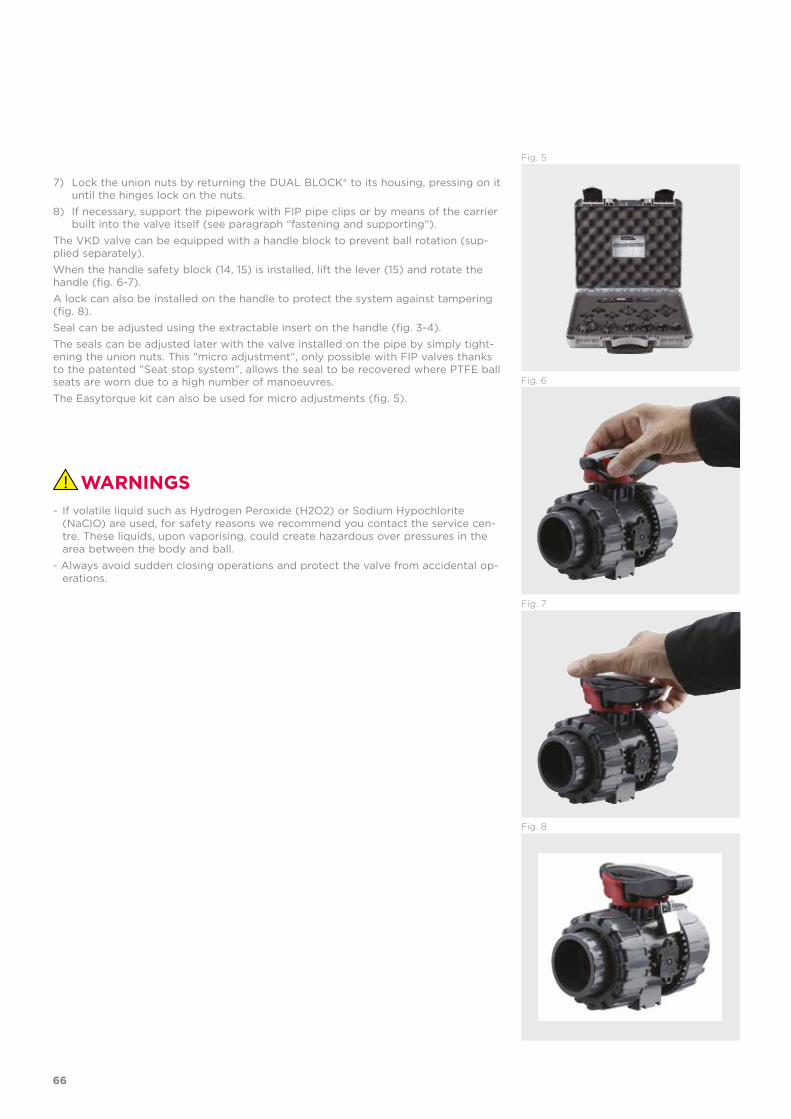
Fig. 5
7) Lock the union nuts by returning the DUAL BLOCK® to its housing, pressing on it until the hinges lock on the nuts.
8) If necessary, support the pipework with FIP pipe clips or by means of the carrier built into the valve itself (see paragraph “fastening and supporting”).
The VKD valve can be equipped with a handle block to prevent ball rotation (sup-plied separately).When the handle safety block (14, 15) is installed, lift the lever (15) and rotate the handle (fig. 6-7).A lock can also be installed on the handle to protect the system against tampering (fig. 8).Seal can be adjusted using the extractable insert on the handle (fig. 3-4). The seals can be adjusted later with the valve installed on the pipe by simply tight-ening the union nuts. This "micro adjustment", only possible with FIP valves thanks to the patented "Seat stop system", allows the seal to be recovered where PTFE ball seats are worn due to a high number of manoeuvres.The Easytorque kit can also be used for micro adjustments (fig. 5).
WARNINGS- If volatile liquid such as Hydrogen Peroxide (H2O2) or Sodium Hypochlorite
(NaCIO) are used, for safety reasons we recommend you contact the service cen-tre. These liquids, upon vaporising, could create hazardous over pressures in the area between the body and ball.
- Always avoid sudden closing operations and protect the valve from accidental op-erations.
Fig. 8
Fig. 7
Fig. 6
66

67

VKD DN 65÷100PVC-C
DUAL BLOCK® 2-way ball valve
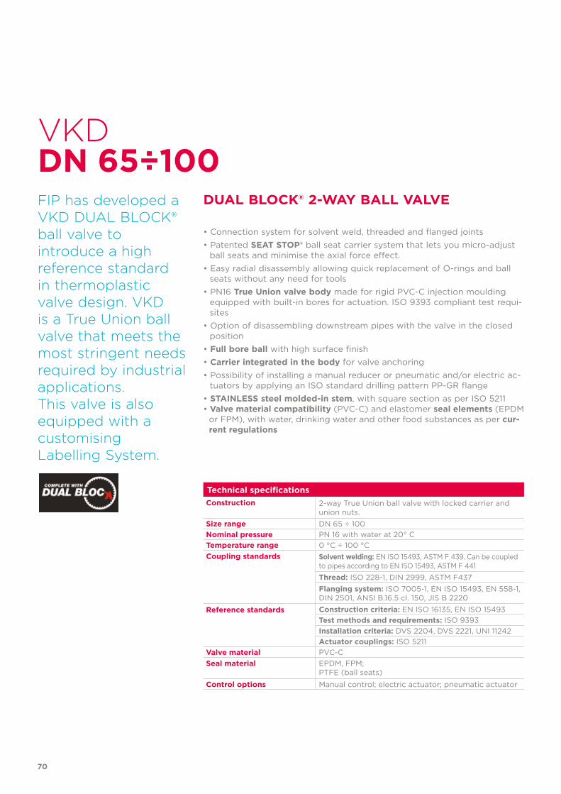
FIP has developed aVKD DUAL BLOCK®ball valve to introduce a high reference standard in thermoplastic valve design. VKD is a True Union ball valve that meets the most stringent needs required by industrial applications.This valve is alsoequipped with acustomisingLabelling System.
70
Technical specificationsConstruction 2-way True Union ball valve with locked carrier and
union nuts.Size range DN 65 ÷ 100Nominal pressure PN 16 with water at 20° CTemperature range 0 °C ÷ 100 °CCoupling standards Solvent welding: EN ISO 15493, ASTM F 439. Can be coupled
to pipes according to EN ISO 15493, ASTM F 441Thread: ISO 228-1, DIN 2999, ASTM F437Flanging system: ISO 7005-1, EN ISO 15493, EN 558-1,DIN 2501, ANSI B.16.5 cl. 150, JIS B 2220
Reference standards Construction criteria: EN ISO 16135, EN ISO 15493Test methods and requirements: ISO 9393Installation criteria: DVS 2204, DVS 2221, UNI 11242Actuator couplings: ISO 5211
Valve material PVC-CSeal material EPDM, FPM;
PTFE (ball seats)
Control options Manual control; electric actuator; pneumatic actuator
VKD
DUAL BLOCK® 2-WAY BALL VALVE
• Connection system for solvent weld, threaded and flanged joints• Patented SEAT STOP® ball seat carrier system that lets you micro-adjust
ball seats and minimise the axial force effect.• Easy radial disassembly allowing quick replacement of O-rings and ball
seats without any need for tools• PN16 True Union valve body made for rigid PVC-C injection moulding
equipped with built-in bores for actuation. ISO 9393 compliant test requi-sites
• Option of disassembling downstream pipes with the valve in the closed position
• Full bore ball with high surface finish• Carrier integrated in the body for valve anchoring• Possibility of installing a manual reducer or pneumatic and/or electric ac-
tuators by applying an ISO standard drilling pattern PP-GR flange• STAINLESS steel molded-in stem, with square section as per ISO 5211• Valve material compatibility (PVC-C) and elastomer seal elements (EPDM
or FPM), with water, drinking water and other food substances as per cur-rent regulations
DN 65÷100
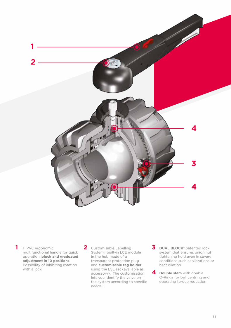
71
1 HIPVC ergonomic multifunctional handle for quick operation, block and graduated adjustment in 10 positions. Possibility of inhibiting rotation with a lock
2 Customisable Labelling System: built-in LCE module in the hub made of a transparent protection plug and customisable tag holder using the LSE set (available as accessory). The customisation lets you identify the valve on the system according to specific needs i
3 DUAL BLOCK® patented lock system that ensures union nut tightening hold even in severe conditions such as vibrations or heat dilation
4 Double stem with double O-Rings for ball centring and operating torque reduction
1
2
3
4
4
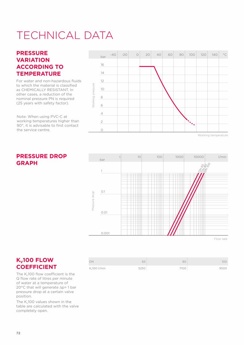
PRESSURE DROP GRAPH
Pre
ssu
re d
rop
Flow rate
bar1 10 100 1000 10000 l/min
1
0.1
0.01
0.001
DN
65
DN
80
DN
100
72
TECHNICAL DATA
-40 -20 0 20 40 60 80 100 120 140 °C
16
14
12
10
8
6
4
2
0
Wo
rkin
g p
ress
ure
Working temperature
barPRESSURE VARIATION ACCORDING TO TEMPERATUREFor water and non-hazardous fluids to which the material is classified as CHEMICALLY RESISTANT. In other cases, a reduction of the nominal pressure PN is required (25 years with safety factor).
KV100 FLOW COEFFICIENTThe Kv100 flow coefficient is the Q flow rate of litres per minute of water at a temperature of 20°C that will generate ∆p= 1 bar pressure drop at a certain valve position.The Kv100 values shown in the table are calculated with the valve completely open.
DN 65 80 100
Kv100 l/min 5250 7100 9500
Note: When using PVC-C at working temperatures higher than 90°, it is advisable to first contact the service centre.
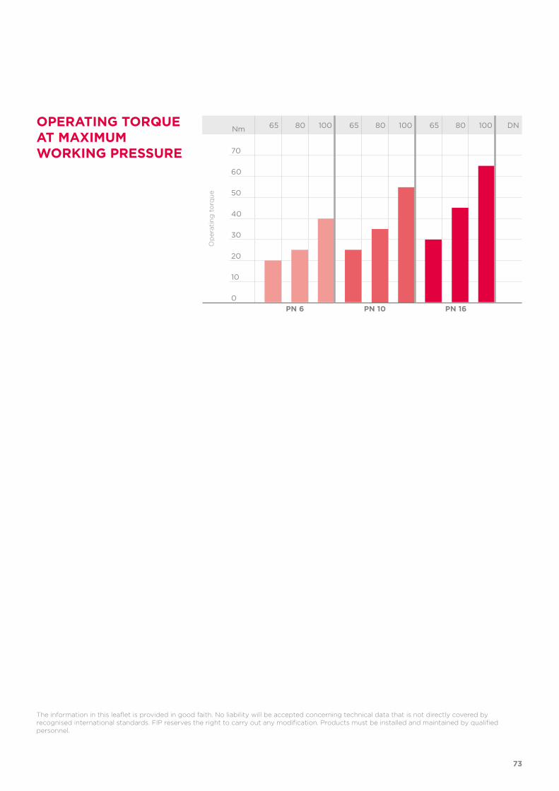
73
The information in this leaflet is provided in good faith. No liability will be accepted concerning technical data that is not directly covered by recognised international standards. FIP reserves the right to carry out any modification. Products must be installed and maintained by qualified personnel.
OPERATING TORQUE AT MAXIMUM WORKING PRESSURE
Nm 65 80 100 65 80 100 65 80 100 DN
70
60
50
40
30
20
10
0
Op
erat
ing
to
rqu
e
PN 6 PN 10 PN 16
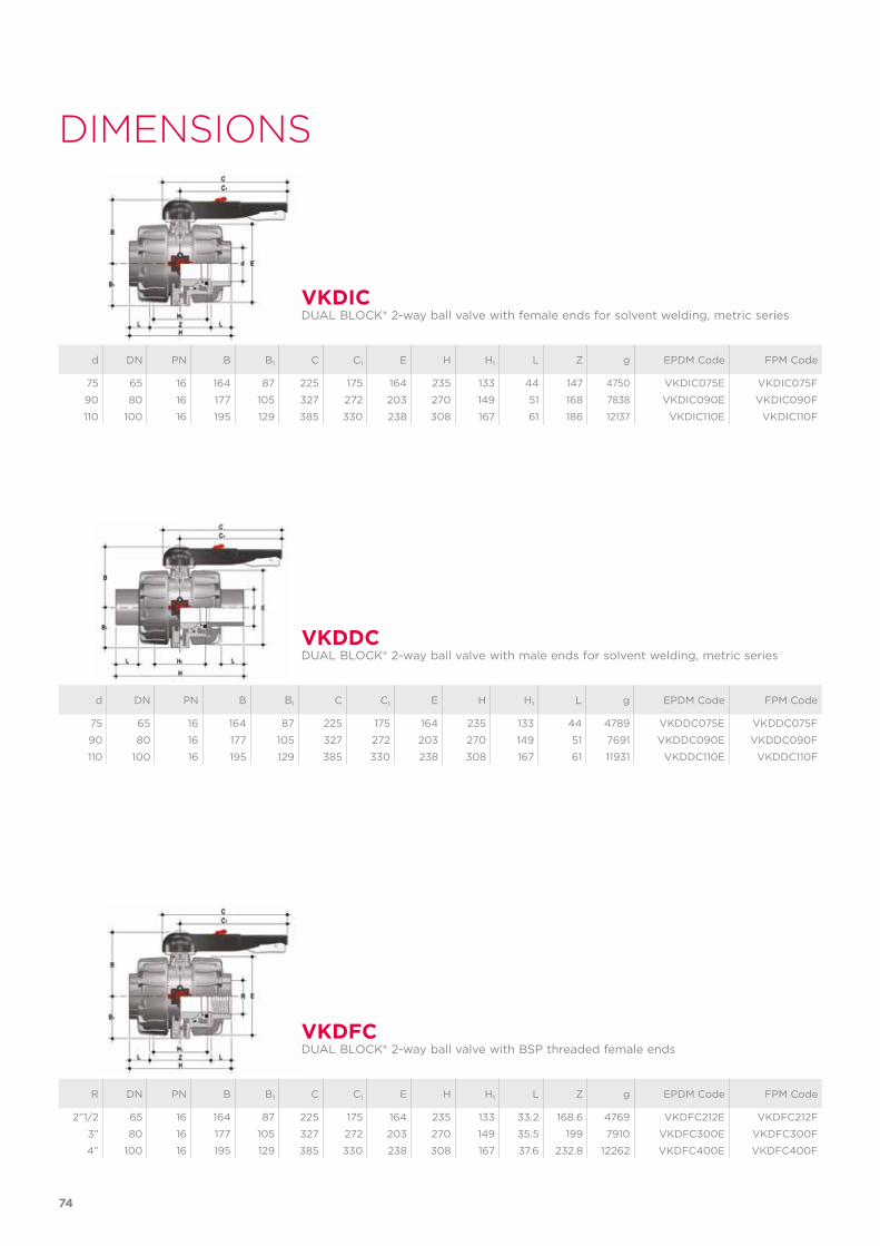
d DN PN B B1 C C1 E H H1 L Z g EPDM Code FPM Code
75 65 16 164 87 225 175 164 235 133 44 147 4750 VKDIC075E VKDIC075F
90 80 16 177 105 327 272 203 270 149 51 168 7838 VKDIC090E VKDIC090F
110 100 16 195 129 385 330 238 308 167 61 186 12137 VKDIC110E VKDIC110F
R DN PN B B1 C C1 E H H1 L Z g EPDM Code FPM Code
2”1/2 65 16 164 87 225 175 164 235 133 33.2 168.6 4769 VKDFC212E VKDFC212F
3” 80 16 177 105 327 272 203 270 149 35.5 199 7910 VKDFC300E VKDFC300F
4” 100 16 195 129 385 330 238 308 167 37.6 232.8 12262 VKDFC400E VKDFC400F
d DN PN B B1 C C1 E H H1 L g EPDM Code FPM Code
75 65 16 164 87 225 175 164 235 133 44 4789 VKDDC075E VKDDC075F
90 80 16 177 105 327 272 203 270 149 51 7691 VKDDC090E VKDDC090F
110 100 16 195 129 385 330 238 308 167 61 11931 VKDDC110E VKDDC110F
VKDIC
VKDFC
VKDDC
DUAL BLOCK® 2-way ball valve with female ends for solvent welding, metric series
DUAL BLOCK® 2-way ball valve with BSP threaded female ends
DUAL BLOCK® 2-way ball valve with male ends for solvent welding, metric series
74
DIMENSIONS
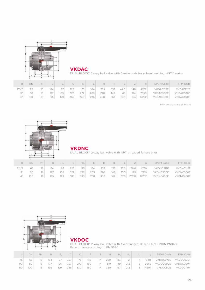
* PPH versions are all PN 10
d DN PN B B1 C C1 E H H1 L Z g EPDM Code FPM Code
2”1/2 65 16 164 87 225 175 164 235 133 44.5 146 4762 VKDAC212E VKDAC212F
3” 80 16 177 105 327 272 203 270 149 48 174 7850 VKDAC300E VKDAC300F
4” 100 16 195 129 385 330 238 308 167 57.5 193 12222 VKDAC400E VKDAC400F
VKDACDUAL BLOCK® 2-way ball valve with female ends for solvent welding, ASTM series
R DN PN B B1 C C1 E H H1 L Z g EPDM Code FPM Code
2”1/2 65 16 164 87 225 175 164 235 133 33.2 168.6 4769 VKDNC212E VKDNC212F
3” 80 16 177 105 327 272 203 270 149 35.5 199 7910 VKDNC300E VKDNC300F
4” 100 16 195 129 385 330 238 308 167 37.6 232.8 12262 VKDNC400E VKDNC400F
VKDNCDUAL BLOCK® 2-way ball valve with NPT threaded female ends
d DN PN B B1 C C1 F f H H1 Sp U g EPDM Code FPM Code
75 65 16 164 87 327 175 145 17 290 133 21 4 6413 VKDOC075E VKDOC075F
90 80 16 177 105 327 272 160 17 310 149 21.5 8 9669 VKDOC090E VKDOC090F
110 100 16 195 129 385 330 180 17 350 167 21.5 8 14697 VKDOC110E VKDOC110F
VKDOCDUAL BLOCK® 2-way ball valve with fixed flanges, drilled EN/ISO/DIN PN10/16.Face to face according to EN 558-1
75
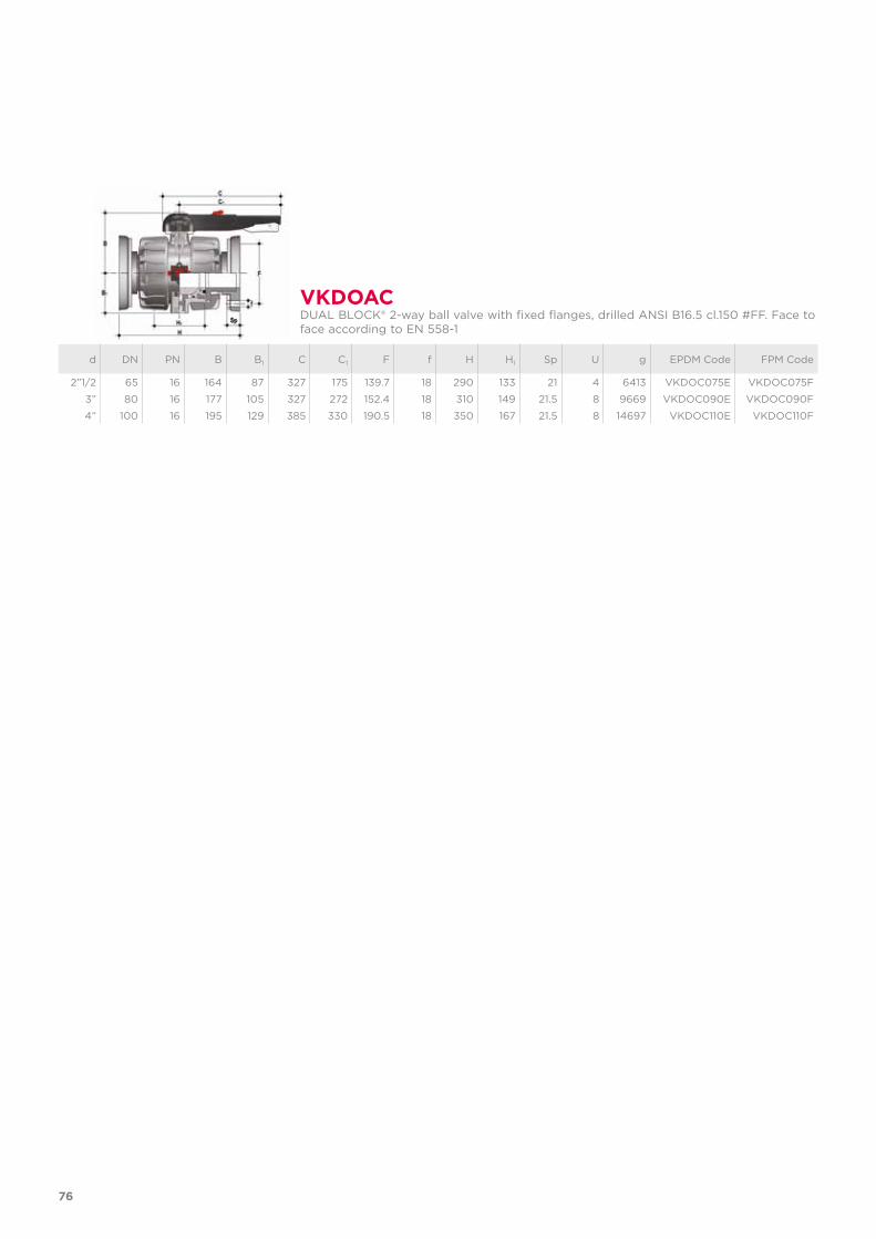
d DN PN B B1 C C1 F f H H1 Sp U g EPDM Code FPM Code
2”1/2 65 16 164 87 327 175 139.7 18 290 133 21 4 6413 VKDOC075E VKDOC075F
3” 80 16 177 105 327 272 152.4 18 310 149 21.5 8 9669 VKDOC090E VKDOC090F
4” 100 16 195 129 385 330 190.5 18 350 167 21.5 8 14697 VKDOC110E VKDOC110F
VKDOACDUAL BLOCK® 2-way ball valve with fixed flanges, drilled ANSI B16.5 cl.150 #FF. Face to face according to EN 558-1
76
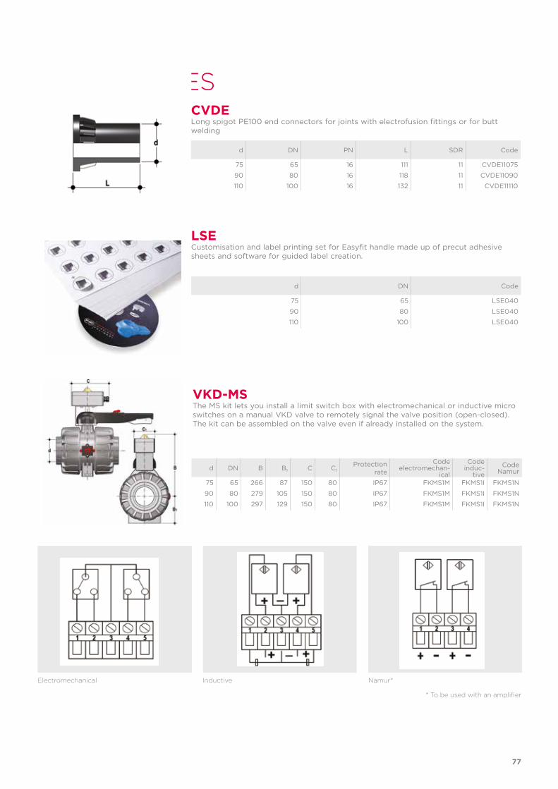
ACCESSORIES
LSECustomisation and label printing set for Easyfit handle made up of precut adhesive sheets and software for guided label creation.
d DN Code
75 65 LSE040
90 80 LSE040
110 100 LSE040
Electromechanical Inductive Namur*
* To be used with an amplifier
VKD-MSThe MS kit lets you install a limit switch box with electromechanical or inductive micro switches on a manual VKD valve to remotely signal the valve position (open-closed). The kit can be assembled on the valve even if already installed on the system.
d DN B B1 C C1Protection
rate
Codeelectromechan-
ical
Codeinduc-
tiveCode
Namur
75 65 266 87 150 80 IP67 FKMS1M FKMS1I FKMS1N
90 80 279 105 150 80 IP67 FKMS1M FKMS1I FKMS1N
110 100 297 129 150 80 IP67 FKMS1M FKMS1I FKMS1N
d DN PN L SDR Code
75 65 16 111 11 CVDE11075
90 80 16 118 11 CVDE11090
110 100 16 132 11 CVDE11110
CVDELong spigot PE100 end connectors for joints with electrofusion fittings or for butt welding
77
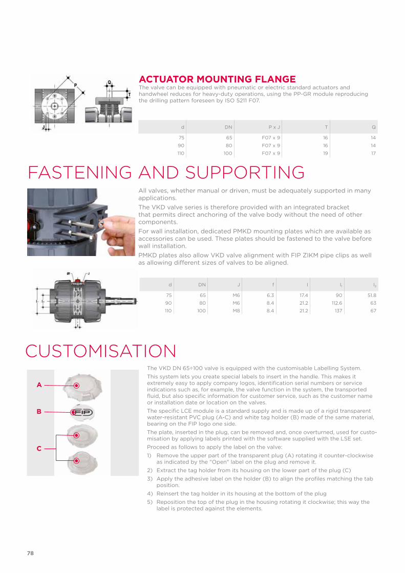
ACTUATOR MOUNTING FLANGEThe valve can be equipped with pneumatic or electric standard actuators and handwheel reduces for heavy-duty operations, using the PP-GR module reproducing the drilling pattern foreseen by ISO 5211 F07.
d DN P x J T Q
75 65 F07 x 9 16 14
90 80 F07 x 9 16 14
110 100 F07 x 9 19 17
FASTENING AND SUPPORTING
d DN J f I I1 I2
75 65 M6 6.3 17.4 90 51.8
90 80 M6 8.4 21.2 112.6 63
110 100 M8 8.4 21.2 137 67
All valves, whether manual or driven, must be adequately supported in many applications. The VKD valve series is therefore provided with an integrated bracket that permits direct anchoring of the valve body without the need of other components.For wall installation, dedicated PMKD mounting plates which are available as accessories can be used. These plates should be fastened to the valve before wall installation. PMKD plates also allow VKD valve alignment with FIP ZIKM pipe clips as well as allowing different sizes of valves to be aligned.
The VKD DN 65÷100 valve is equipped with the customisable Labelling System.This system lets you create special labels to insert in the handle. This makes it extremely easy to apply company logos, identification serial numbers or service indications such as, for example, the valve function in the system, the transported fluid, but also specific information for customer service, such as the customer name or installation date or location on the valves.The specific LCE module is a standard supply and is made up of a rigid transparent water-resistant PVC plug (A-C) and white tag holder (B) made of the same material, bearing on the FIP logo one side.The plate, inserted in the plug, can be removed and, once overturned, used for custo-misation by applying labels printed with the software supplied with the LSE set.Proceed as follows to apply the label on the valve:1) Remove the upper part of the transparent plug (A) rotating it counter-clockwise
as indicated by the "Open" label on the plug and remove it.2) Extract the tag holder from its housing on the lower part of the plug (C)3) Apply the adhesive label on the holder (B) to align the profiles matching the tab
position.4) Reinsert the tag holder in its housing at the bottom of the plug5) Reposition the top of the plug in the housing rotating it clockwise; this way the
label is protected against the elements.
CUSTOMISATION
A
B
C
78
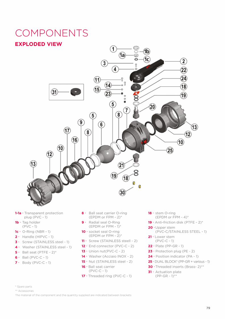
COMPONENTSEXPLODED VIEW
1-1a Transparent protection plug (PVC - 1)1b Tag holder (PVC - 1)1c O-Ring (NBR - 1)2 Handle (HIPVC - 1)3 Screw (STAINLESS steel - 1)4 Washer (STAINLESS steel - 1)5 Ball seat (PTFE - 2)*6 Ball (PVC-C - 1)7 Body (PVC-C - 1)
* Spare parts
** Accessories
The material of the component and the quantity supplied are indicated between brackets
8 Ball seat carrier O-ring (EPDM or FPM - 2)*9 Radial seal O-Ring (EPDM or FPM - 1)*10 socket seal O-ring (EPDM or FPM - 2)*11 Screw (STAINLESS steell - 2)12 End connector (PVC-C - 2)13 Union nut(PVC-C - 2)14 Washer (Acciaio INOX - 2)15 Nut (STAINLESS steel - 2)16 Ball seat carrier (PVC-C - 1)17 Threaded ring (PVC-C - 1)
18 stem O-ring (EPDM or FPM - 4)*19 Anti-friction disk (PTFE - 2)*20 Upper stem (PVC-C/STAINLESS STEEL - 1)21 Lower stem (PVC-C - 1)22 Plate (PP-GR - 1)23 Protection plug (PE - 2)24 Position indicator (PA - 1)25 DUAL BLOCK® (PP-GR + various - 1)30 Threaded inserts (Brass- 2)**31 Actuation plate (PP-GR - 1)**
79
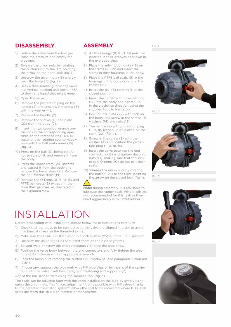
INSTALLATIONBefore proceeding with installation. please follow these instructions carefully:1) Check that the pipes to be connected to the valve are aligned in order to avoid
mechanical stress on the threaded joints.2) Make sure the DUAL BLOCK® union nut lock system (25) is in the FREE position.3) Unscrew the union nuts (13) and insert them on the pipe segments.4) Solvent weld or screw the end connectors (12) onto the pipe ends.5) Position the valve body between the end connectors and fully tighten the union
nuts (13) clockwise with an appropriate wrench.6) Lock the union nuts rotating the button (25) clockwise (see paragraph "union nut
lock").7) If necessary, support the pipework with FIP pipe clips or by means of the carrier
built into the valve itself (see paragraph “fastening and supporting”).Adjust the ball seat carriers using the supplied tool (fig. 3).The seals can be adjusted later with the valve installed on the pipe by simply tight-ening the union nuts. This "micro adjustment", only possible with FIP valves thanks to the patented "Seat stop system", allows the seal to be recovered where PTFE ball seats are worn due to a high number of manoeuvres.
DISASSEMBLY ASSEMBLY1) Isolate the valve from the line (re-
lease the pressure and empty the pipeline).
2) Release the union nuts by rotating the button (25) to the left, pointing the arrow on the open lock (fig. 1).
3) Unscrew the union nuts (13) and ex-tract the body (7) (fig. 2).
4) Before disassembling, hold the valve in a vertical position and open it 45° to drain any liquid that might remain.
5) Open the valve.6) Remove the protection plug on the
handle (2) and unscrew the screw (3) with the washer (4).
7) Remove the handle (2).8) Remove the screws (11) and plate
(22) from the body (7).9) Insert the two supplied wrench pro-
trusions in the corresponding aper-tures on the threaded ring (17), ex-tracting it by rotating counter-clock-wise with the ball seat carrier (16) (fig. 3).
10) Press on the ball (6), being careful not to scratch it, and remove it from the body.
11) Press the upper stem (20) inwards and extract it from the body and remove the lower stem (21). Remove the anti-friction disks (19).
12) Remove the O-Rings (8, 9, 10, 18) and PTFE ball seats (5) extracting them from their grooves, as illustrated in the exploded view.
1) All the O-rings (8, 9, 10, 18) must be inserted in their grooves as shown in the exploded view.
2) Place the anti-friction disks (19) on the stems (20-21) and insert the stems in their housings in the body.
3) Place the PTFE ball seats (5) in the housings in the body (7) and in the carrier (16).
4) Insert the ball (6) rotating it to the closed position.
5) Insert the carrier with threaded ring (17) into the body and tighten up in the clockwise direction using the supplied tool, to limit stop.
6) Position the plate (22) with rack on the body, and screw in the screws (11) washers (14) and nuts (15).
7) The handle (2) with protection plug (1, 1a, 1b, 1c) should be placed on the stem (20) (fig. 4).
8) Screw in the screw (3) with the washer (4) and position the protec-tion plug (1, 1a, 1b, 1c).
9) Insert the valve between the end connectors (12) and tighten the union nuts (13), making sure that the sock-et seal O-rings (10) do not exit their seats.
10) Release the union nuts by rotating the button (25) to the right, pointing the arrow on the closed lock (fig. 1).
Note: during assembly, it is advisable to lubricate the rubber seals. Mineral oils are not recommended for this task as they react aggressively with EPDM rubber.
Fig. 3
Fig. 4
Fig. 2
Fig. 1
80
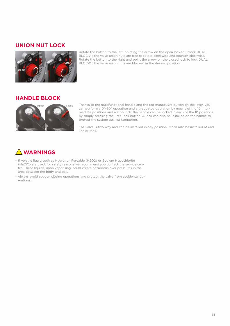
WARNINGS- If volatile liquid such as Hydrogen Peroxide (H2O2) or Sodium Hypochlorite
(NaCIO) are used, for safety reasons we recommend you contact the service cen-tre. These liquids, upon vaporising, could create hazardous over pressures in the area between the body and ball.
- Always avoid sudden closing operations and protect the valve from accidental op-erations.
UNION NUT LOCK
HANDLE BLOCK
Rotate the button to the left, pointing the arrow on the open lock to unlock DUAL BLOCK® : the valve union nuts are free to rotate clockwise and counter-clockwise.Rotate the button to the right and point the arrow on the closed lock to lock DUAL BLOCK® : the valve union nuts are blocked in the desired position.
Thanks to the multifunctional handle and the red manoeuvre button on the lever, you can perform a 0°-90° operation and a graduated operation by means of the 10 inter-mediate positions and a stop lock: the handle can be locked in each of the 10 positions by simply pressing the Free-lock button. A lock can also be installed on the handle to protect the system against tampering.
The valve is two-way and can be installed in any position. It can also be installed at end line or tank.
FREE
LOCK
FREE LOCK
81

TKD DN 10÷50PVC-C
DUAL BLOCK® 3-way ball valve
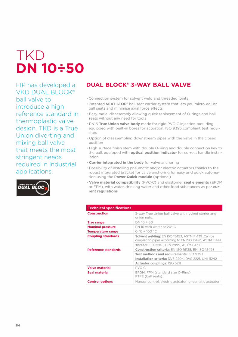
84
Technical specificationsConstruction 3-way True Union ball valve with locked carrier and
union nuts.Size range DN 10 ÷ 50Nominal pressure PN 16 with water at 20° CTemperature range 0 °C ÷ 100 °CCoupling standards Solvent welding: EN ISO 15493, ASTM F 439. Can be
coupled to pipes according to EN ISO 15493, ASTM F 441Thread: ISO 228-1, DIN 2999, ASTM F437
Reference standards Construction criteria: EN ISO 16135, EN ISO 15493Test methods and requirements: ISO 9393Installation criteria: DVS 2204, DVS 2221, UNI 11242Actuator couplings: ISO 5211
Valve material PVC-CSeal material EPDM, FPM (standard size O-Ring);
PTFE (ball seats)
Control options Manual control; electric actuator; pneumatic actuator
TKD
FIP has developed aVKD DUAL BLOCK®ball valve to introduce a high reference standard in thermoplastic valve design. TKD is a True Union diverting and mixing ball valve that meets the most stringent needs required in industrial applications.
DUAL BLOCK® 3-WAY BALL VALVE
• Connection system for solvent weld and threaded joints• Patented SEAT STOP® ball seat carrier system that lets you micro-adjust
ball seats and minimise axial force effects• Easy radial disassembly allowing quick replacement of O-rings and ball
seats without any need for tools• PN16 True Union valve body made for rigid PVC-C injection moulding
equipped with built-in bores for actuation. ISO 9393 compliant test requi-sites
• Option of disassembling downstream pipes with the valve in the closed position
• High surface finish stem with double O-Ring and double connection key to the ball, equipped with optical position indicator for correct handle instal-lation
• Carrier integrated in the body for valve anchoring• Possibility of installing pneumatic and/or electric actuators thanks to the
robust integrated bracket for valve anchoring for easy and quick automa-tion using the Power Quick module (optional)
• Valve material compatibility (PVC-C) and elastomer seal elements (EPDM or FPM), with water, drinking water and other food substances as per cur-rent regulations
DN 10÷50
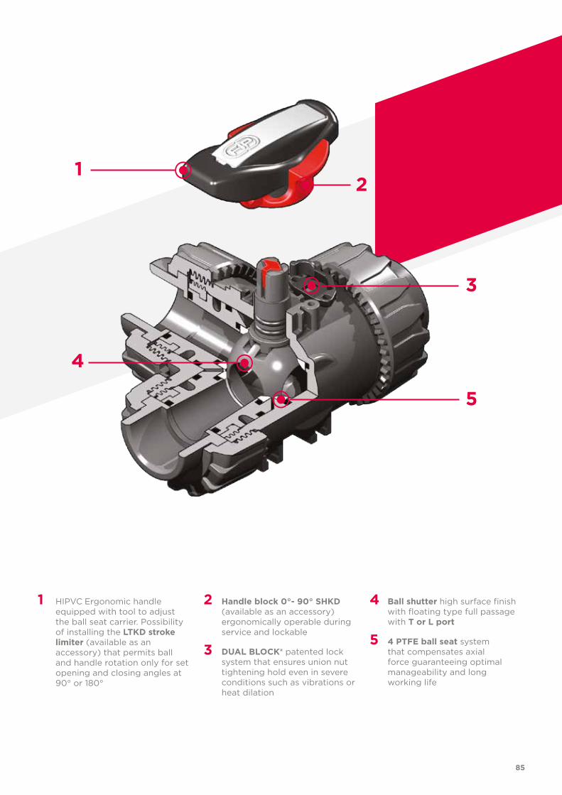
1
4
2
3
5
85
1 HIPVC Ergonomic handle equipped with tool to adjust the ball seat carrier. Possibility of installing the LTKD stroke limiter (available as an accessory) that permits ball and handle rotation only for set opening and closing angles at 90° or 180°
2 Handle block 0°- 90° SHKD (available as an accessory) ergonomically operable during service and lockable
3 DUAL BLOCK® patented lock system that ensures union nut tightening hold even in severe conditions such as vibrations or heat dilation
4 Ball shutter high surface finish with floating type full passage with T or L port
5 4 PTFE ball seat system that compensates axial force guaranteeing optimal manageability and long working life
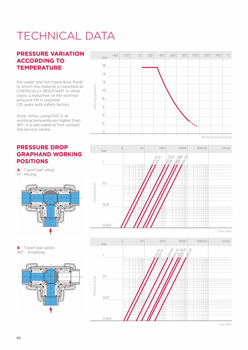
86
TECHNICAL DATA
-40 -20 0 20 40 60 80 100 120 140 °C
16
14
12
10
8
6
4
2
0
Wo
rkin
g p
ress
ure
Working temperature
barPRESSURE VARIATION ACCORDING TO TEMPERATURE
For water and non-hazardous fluids to which the material is classified as CHEMICALLY RESISTANT. In other cases, a reduction of the nominal pressure PN is required (25 years with safety factor).
PRESSURE DROP GRAPHAND WORKING POSITIONS
Pre
ssu
re d
rop
Flow rate
bar1 10 100 1000 10000 l/min
1
0.1
0.01
0.001
DN
10D
N 15
DN
20
DN
25
DN
32
DN
40
DN
50
A - T-port ball valve:0°- Mixing
Pre
ssu
re d
rop
Flow rate
bar1 10 100 1000 10000 l/min
1
0.1
0.01
0.001
DN
10
DN
20
DN
15
DN
25
DN
32
DN
40
DN
50B - T-port ball valve:
90° - Diverting
Note: When using PVC-C at working temperatures higher than 90°, it is advisable to first contact the service centre.
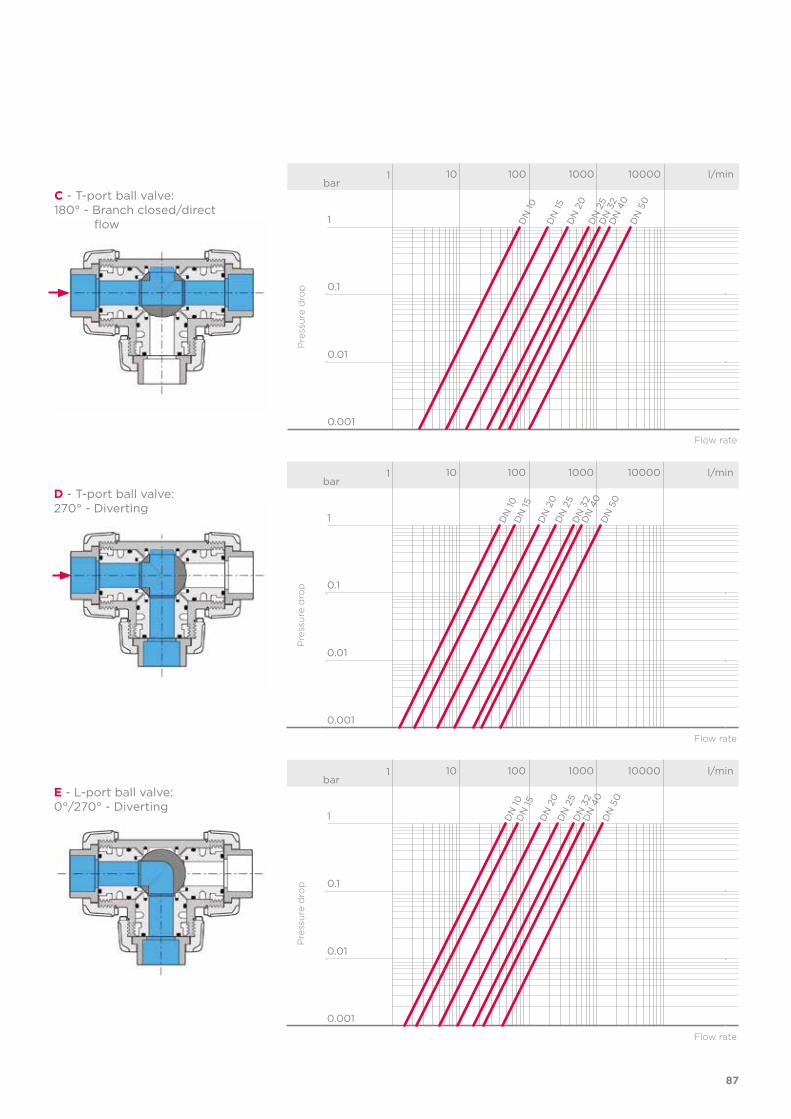
87
Pre
ssu
re d
rop
Flow rate
bar1 10 100 1000 10000 l/min
1
0.1
0.01
0.001
DN
15
DN
10
DN
20
DN
25
DN
32
DN
40
DN
50C - T-port ball valve:
180° - Branch closed/direct flow
Pre
ssu
re d
rop
Flow rate
bar1 10 100 1000 10000 l/min
1
0.1
0.01
0.001
DN
15
DN
10
DN
20
DN
25
DN
32
DN
40
DN
50D - T-port ball valve:
270° - Diverting
Pre
ssu
re d
rop
Flow rate
bar1 10 100 1000 10000 l/min
1
0.1
0.01
0.001
DN
15
DN
10
DN
20
DN
25
DN
32
DN
40
DN
50E - L-port ball valve:
0°/270° - Diverting
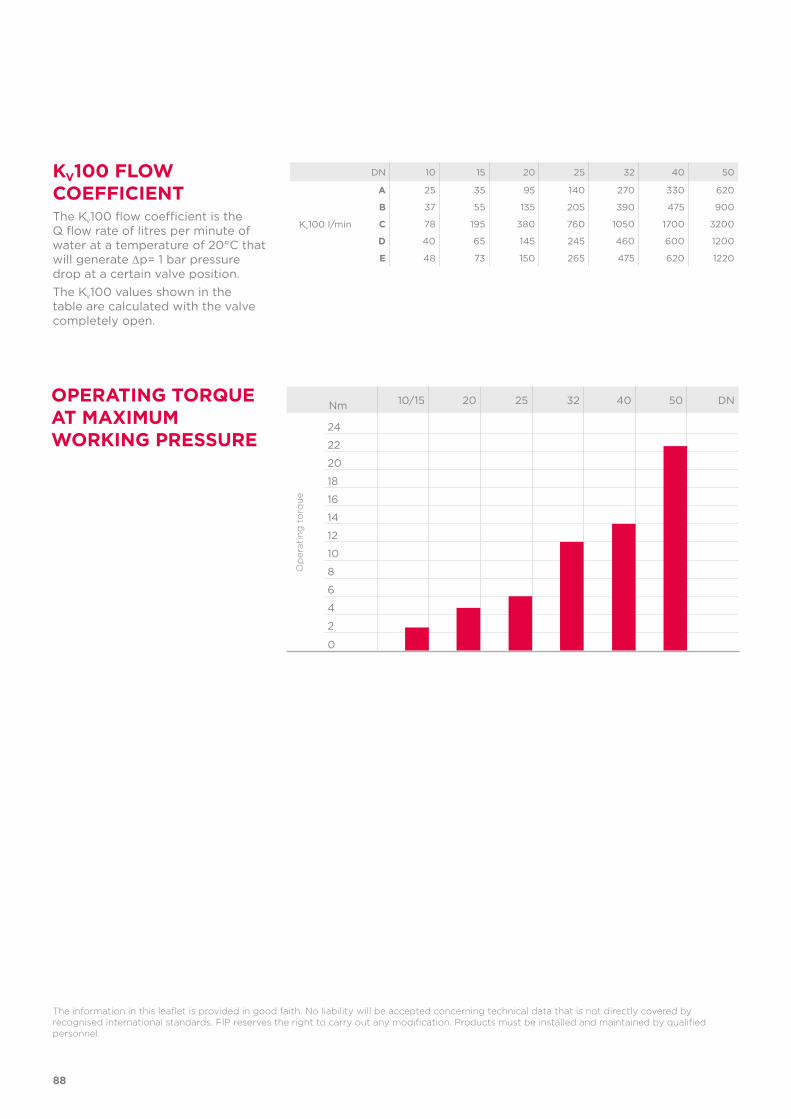
88
DN 10 15 20 25 32 40 50
Kv100 l/min
A 25 35 95 140 270 330 620
B 37 55 135 205 390 475 900
C 78 195 380 760 1050 1700 3200
D 40 65 145 245 460 600 1200
E 48 73 150 265 475 620 1220
KV100 FLOW COEFFICIENTThe Kv100 flow coefficient is the Q flow rate of litres per minute of water at a temperature of 20°C that will generate ∆p= 1 bar pressure drop at a certain valve position.The Kv100 values shown in the table are calculated with the valve completely open.
OPERATING TORQUE AT MAXIMUM WORKING PRESSURE
The information in this leaflet is provided in good faith. No liability will be accepted concerning technical data that is not directly covered by recognised international standards. FIP reserves the right to carry out any modification. Products must be installed and maintained by qualified personnel.
Nm 10/15 20 25 32 40 50 DN
24
22
20
18
16
14
12
10
8
6
4
2
0
Op
erat
ing
to
rqu
e
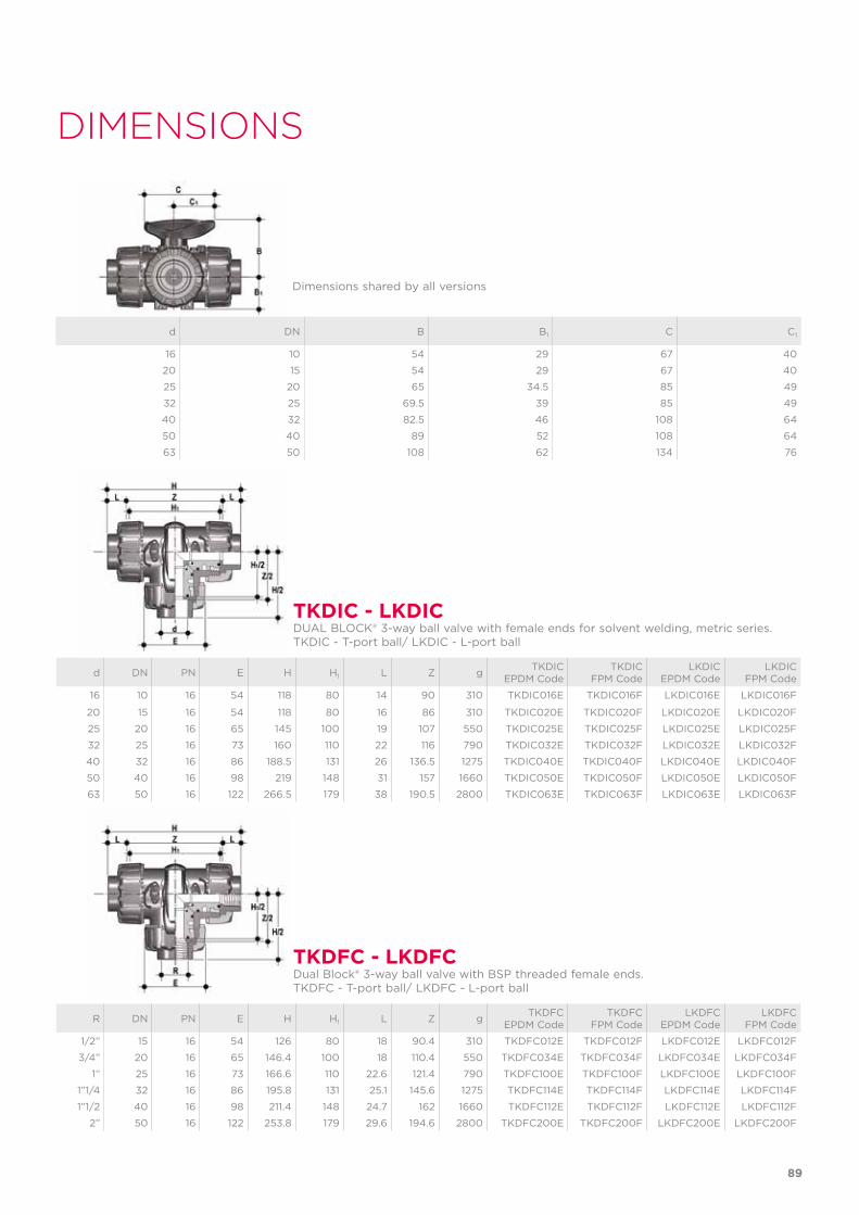
89
d DN PN E H H1 L Z g TKDICEPDM Code
TKDICFPM Code
LKDICEPDM Code
LKDICFPM Code
16 10 16 54 118 80 14 90 310 TKDIC016E TKDIC016F LKDIC016E LKDIC016F
20 15 16 54 118 80 16 86 310 TKDIC020E TKDIC020F LKDIC020E LKDIC020F
25 20 16 65 145 100 19 107 550 TKDIC025E TKDIC025F LKDIC025E LKDIC025F
32 25 16 73 160 110 22 116 790 TKDIC032E TKDIC032F LKDIC032E LKDIC032F
40 32 16 86 188.5 131 26 136.5 1275 TKDIC040E TKDIC040F LKDIC040E LKDIC040F
50 40 16 98 219 148 31 157 1660 TKDIC050E TKDIC050F LKDIC050E LKDIC050F
63 50 16 122 266.5 179 38 190.5 2800 TKDIC063E TKDIC063F LKDIC063E LKDIC063F
R DN PN E H H1 L Z g TKDFCEPDM Code
TKDFCFPM Code
LKDFCEPDM Code
LKDFCFPM Code
1/2” 15 16 54 126 80 18 90.4 310 TKDFC012E TKDFC012F LKDFC012E LKDFC012F
3/4” 20 16 65 146.4 100 18 110.4 550 TKDFC034E TKDFC034F LKDFC034E LKDFC034F
1” 25 16 73 166.6 110 22.6 121.4 790 TKDFC100E TKDFC100F LKDFC100E LKDFC100F
1”1/4 32 16 86 195.8 131 25.1 145.6 1275 TKDFC114E TKDFC114F LKDFC114E LKDFC114F
1”1/2 40 16 98 211.4 148 24.7 162 1660 TKDFC112E TKDFC112F LKDFC112E LKDFC112F
2” 50 16 122 253.8 179 29.6 194.6 2800 TKDFC200E TKDFC200F LKDFC200E LKDFC200F
Dimensions shared by all versions
d DN B B1 C C1
16 10 54 29 67 40
20 15 54 29 67 40
25 20 65 34.5 85 49
32 25 69.5 39 85 49
40 32 82.5 46 108 64
50 40 89 52 108 64
63 50 108 62 134 76
TKDIC - LKDIC
TKDFC - LKDFC
DUAL BLOCK® 3-way ball valve with female ends for solvent welding, metric series. TKDIC - T-port ball/ LKDIC - L-port ball
Dual Block® 3-way ball valve with BSP threaded female ends.TKDFC - T-port ball/ LKDFC - L-port ball
DIMENSIONS
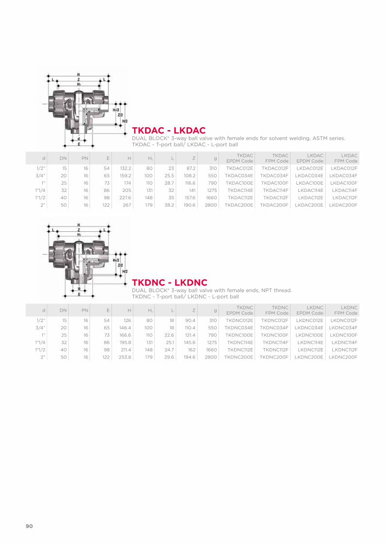
d DN PN E H H1 L Z g TKDACEPDM Code
TKDACFPM Code
LKDACEPDM Code
LKDACFPM Code
1/2” 15 16 54 132.2 80 23 87.2 310 TKDAC012E TKDAC012F LKDAC012E LKDAC012F
3/4” 20 16 65 159.2 100 25.5 108.2 550 TKDAC034E TKDAC034F LKDAC034E LKDAC034F
1” 25 16 73 174 110 28.7 116.6 790 TKDAC100E TKDAC100F LKDAC100E LKDAC100F
1”1/4 32 16 86 205 131 32 141 1275 TKDAC114E TKDAC114F LKDAC114E LKDAC114F
1”1/2 40 16 98 227.6 148 35 157.6 1660 TKDAC112E TKDAC112F LKDAC112E LKDAC112F
2” 50 16 122 267 179 38.2 190.6 2800 TKDAC200E TKDAC200F LKDAC200E LKDAC200F
d DN PN E H H1 L Z g TKDNCEPDM Code
TKDNCFPM Code
LKDNCEPDM Code
LKDNCFPM Code
1/2” 15 16 54 126 80 18 90.4 310 TKDNC012E TKDNC012F LKDNC012E LKDNC012F
3/4” 20 16 65 146.4 100 18 110.4 550 TKDNC034E TKDNC034F LKDNC034E LKDNC034F
1” 25 16 73 166.6 110 22.6 121.4 790 TKDNC100E TKDNC100F LKDNC100E LKDNC100F
1”1/4 32 16 86 195.8 131 25.1 145.6 1275 TKDNC114E TKDNC114F LKDNC114E LKDNC114F
1”1/2 40 16 98 211.4 148 24.7 162 1660 TKDNC112E TKDNC112F LKDNC112E LKDNC112F
2” 50 16 122 253.8 179 29.6 194.6 2800 TKDNC200E TKDNC200F LKDNC200E LKDNC200F
TKDAC - LKDAC
TKDNC - LKDNC
DUAL BLOCK® 3-way ball valve with female ends for solvent welding, ASTM series. TKDAC - T-port ball/ LKDAC - L-port ball
DUAL BLOCK® 3-way ball valve with female ends, NPT thread.TKDNC - T-port ball/ LKDNC - L-port ball
90
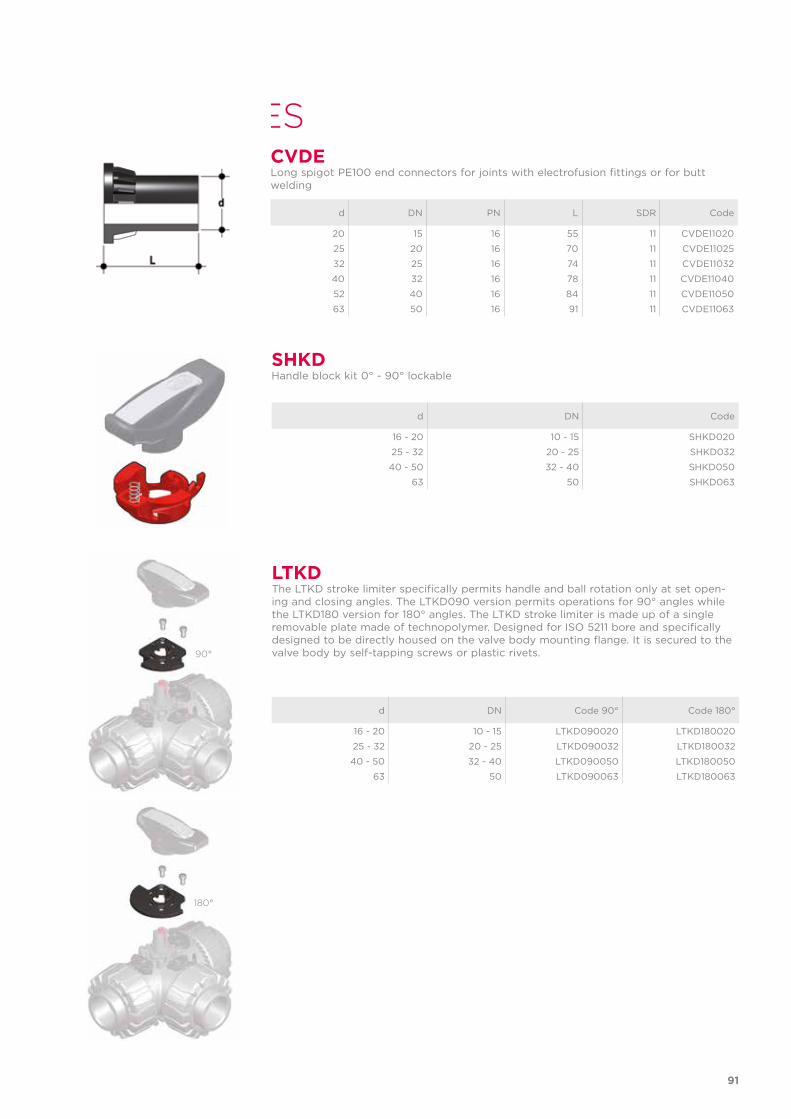
ACCESSORIES
d DN Code 90° Code 180°
16 - 20 10 - 15 LTKD090020 LTKD180020
25 - 32 20 - 25 LTKD090032 LTKD180032
40 - 50 32 - 40 LTKD090050 LTKD180050
63 50 LTKD090063 LTKD180063
LTKDThe LTKD stroke limiter specifically permits handle and ball rotation only at set open-ing and closing angles. The LTKD090 version permits operations for 90° angles while the LTKD180 version for 180° angles. The LTKD stroke limiter is made up of a single removable plate made of technopolymer. Designed for ISO 5211 bore and specifically designed to be directly housed on the valve body mounting flange. It is secured to the valve body by self-tapping screws or plastic rivets.
d DN Code
16 - 20 10 - 15 SHKD020
25 - 32 20 - 25 SHKD032
40 - 50 32 - 40 SHKD050
63 50 SHKD063
SHKDHandle block kit 0° - 90° lockable
90°
180°
d DN PN L SDR Code
20 15 16 55 11 CVDE11020
25 20 16 70 11 CVDE11025
32 25 16 74 11 CVDE11032
40 32 16 78 11 CVDE11040
52 40 16 84 11 CVDE11050
63 50 16 91 11 CVDE11063
CVDELong spigot PE100 end connectors for joints with electrofusion fittings or for butt welding
91
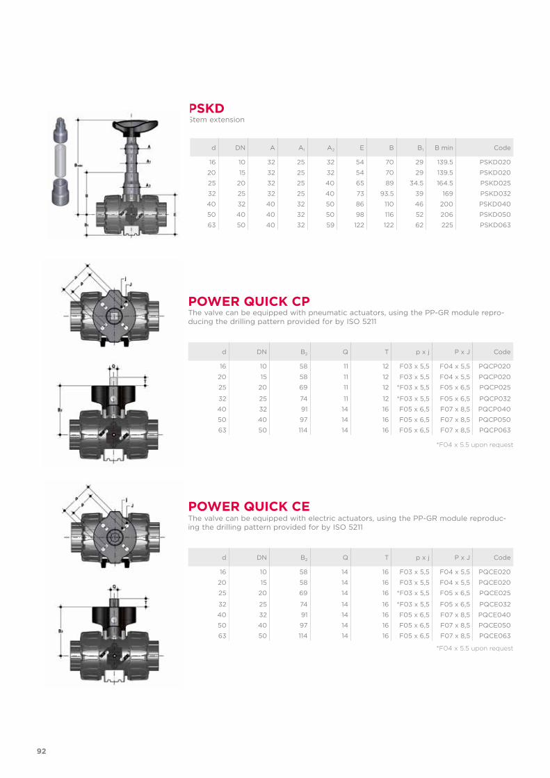
POWER QUICK CEThe valve can be equipped with electric actuators, using the PP-GR module reproduc-ing the drilling pattern provided for by ISO 5211
d DN B2 Q T p x j P x J Code
16 10 58 14 16 F03 x 5,5 F04 x 5,5 PQCE020
20 15 58 14 16 F03 x 5,5 F04 x 5,5 PQCE020
25 20 69 14 16 *F03 x 5,5 F05 x 6,5 PQCE025
32 25 74 14 16 *F03 x 5,5 F05 x 6,5 PQCE032
40 32 91 14 16 F05 x 6,5 F07 x 8,5 PQCE040
50 40 97 14 16 F05 x 6,5 F07 x 8,5 PQCE050
63 50 114 14 16 F05 x 6,5 F07 x 8,5 PQCE063
POWER QUICK CPThe valve can be equipped with pneumatic actuators, using the PP-GR module repro-ducing the drilling pattern provided for by ISO 5211
d DN B2 Q T p x j P x J Code
16 10 58 11 12 F03 x 5,5 F04 x 5,5 PQCP020
20 15 58 11 12 F03 x 5,5 F04 x 5,5 PQCP020
25 20 69 11 12 *F03 x 5,5 F05 x 6,5 PQCP025
32 25 74 11 12 *F03 x 5,5 F05 x 6,5 PQCP032
40 32 91 14 16 F05 x 6,5 F07 x 8,5 PQCP040
50 40 97 14 16 F05 x 6,5 F07 x 8,5 PQCP050
63 50 114 14 16 F05 x 6,5 F07 x 8,5 PQCP063
*F04 x 5.5 upon request
*F04 x 5.5 upon request
d DN A A1 A2 E B B1 B min Code
16 10 32 25 32 54 70 29 139.5 PSKD020
20 15 32 25 32 54 70 29 139.5 PSKD020
25 20 32 25 40 65 89 34.5 164.5 PSKD025
32 25 32 25 40 73 93.5 39 169 PSKD032
40 32 40 32 50 86 110 46 200 PSKD040
50 40 40 32 50 98 116 52 206 PSKD050
63 50 40 32 59 122 122 62 225 PSKD063
PSKDStem extension
92
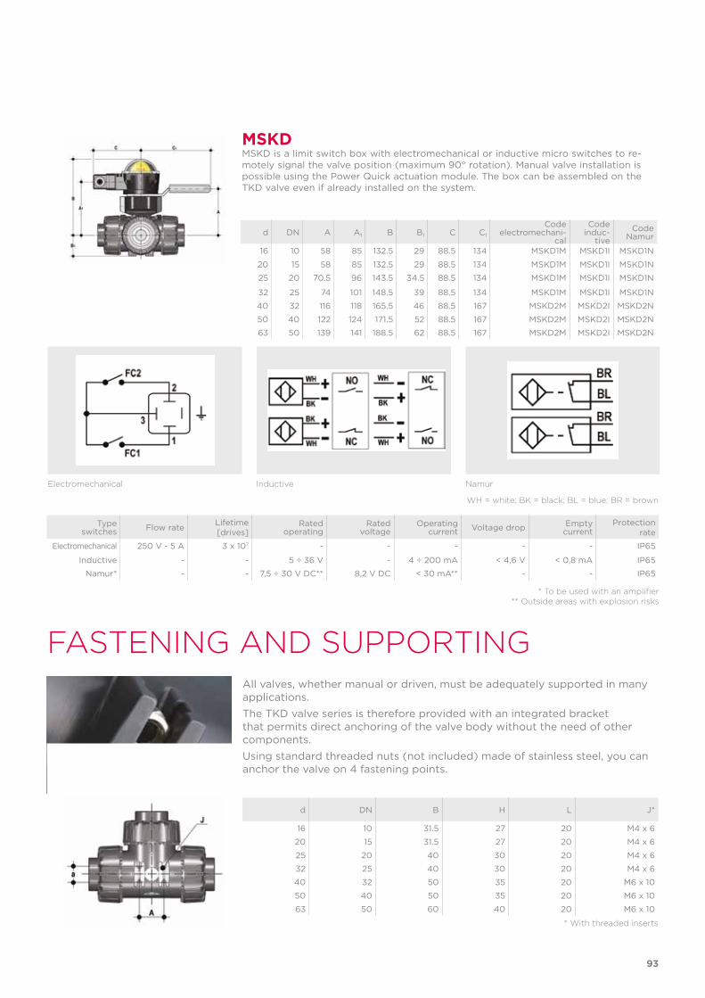
FASTENING AND SUPPORTING
d DN B H L J*
16 10 31.5 27 20 M4 x 6
20 15 31.5 27 20 M4 x 6
25 20 40 30 20 M4 x 6
32 25 40 30 20 M4 x 6
40 32 50 35 20 M6 x 10
50 40 50 35 20 M6 x 10
63 50 60 40 20 M6 x 10
* With threaded inserts
All valves, whether manual or driven, must be adequately supported in many applications. The TKD valve series is therefore provided with an integrated bracket that permits direct anchoring of the valve body without the need of other components. Using standard threaded nuts (not included) made of stainless steel, you can anchor the valve on 4 fastening points.
Type switches Flow rate Lifetime
[drives]Rated
operatingRated
voltageOperating
current Voltage drop Empty current
Protection rate
Electromechanical 250 V - 5 A 3 x 10⁷ - - - - - IP65
Inductive - - 5 ÷ 36 V - 4 ÷ 200 mA < 4,6 V < 0,8 mA IP65
Namur* - - 7,5 ÷ 30 V DC** 8,2 V DC < 30 mA** - - IP65
* To be used with an amplifier** Outside areas with explosion risks
Electromechanical Inductive Namur
WH = white; BK = black; BL = blue; BR = brown
MSKDMSKD is a limit switch box with electromechanical or inductive micro switches to re-motely signal the valve position (maximum 90° rotation). Manual valve installation is possible using the Power Quick actuation module. The box can be assembled on the TKD valve even if already installed on the system.
d DN A A1 B B1 C C1
Codeelectromechani-
cal
Codeinduc-
tiveCode
Namur
16 10 58 85 132.5 29 88.5 134 MSKD1M MSKD1I MSKD1N
20 15 58 85 132.5 29 88.5 134 MSKD1M MSKD1I MSKD1N
25 20 70.5 96 143.5 34.5 88.5 134 MSKD1M MSKD1I MSKD1N
32 25 74 101 148.5 39 88.5 134 MSKD1M MSKD1I MSKD1N
40 32 116 118 165.5 46 88.5 167 MSKD2M MSKD2I MSKD2N
50 40 122 124 171.5 52 88.5 167 MSKD2M MSKD2I MSKD2N
63 50 139 141 188.5 62 88.5 167 MSKD2M MSKD2I MSKD2N
93
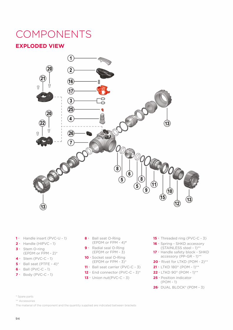
COMPONENTSEXPLODED VIEW
1 Handle insert (PVC-U - 1)2 Handle (HIPVC - 1)3 Stem O-ring (EPDM or FPM - 2)*4 Stem (PVC-C - 1)5 Ball seat (PTFE - 4)*6 Ball (PVC-C - 1)7 Body (PVC-C - 1)
* Spare parts
** Accessories
The material of the component and the quantity supplied are indicated between brackets
8 Ball seat O-Ring (EPDM or FPM - 4)*9 Radial seal O-Ring (EPDM or FPM - 3)10 Socket seal O-Ring (EPDM or FPM - 3)*11 Ball seat carrier (PVC-C - 3)12 End connector (PVC-C - 3)*13 Union nut(PVC-C - 3)
15 Threaded ring (PVC-C - 3)16 Spring - SHKD accessory (STAINLESS steel - 1)**17 Handle safety block - SHKD accessory (PP-GR - 1)**20 Rivet for LTKD (POM - 2)**21 LTKD 180° (POM - 1)**22 LTKD 90° (POM - 1)**25 Position indicator (POM - 1)26 DUAL BLOCK® (POM - 3)
94
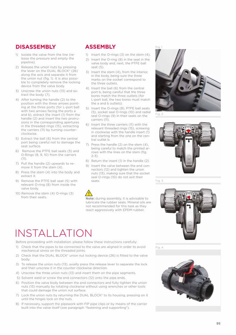
INSTALLATIONBefore proceeding with installation. please follow these instructions carefully:1) Check that the pipes to be connected to the valve are aligned in order to avoid
mechanical stress on the threaded joints.2) Check that the DUAL BLOCK® union nut locking device (26) is fitted to the valve
body.3) To release the union nuts (13), axially press the release lever to separate the lock
and then unscrew it in the counter-clockwise direction.4) Unscrew the three union nuts (13) and insert them on the pipe segments. 5) Solvent weld or screw the end connectors (12) onto the pipe ends.6) Position the valve body between the end connectors and fully tighten the union
nuts (13) manually by rotating clockwise without using wrenches or other tools that could damage the union nut surface.
7) Lock the union nuts by returning the DUAL BLOCK® to its housing, pressing on it until the hinges lock on the nuts.
8) If necessary, support the pipework with FIP pipe clips or by means of the carrier built-into the valve itself (see paragraph “fastening and supporting”).
DISASSEMBLY ASSEMBLY1) Isolate the valve from the line (re-
lease the pressure and empty the pipeline).
2) Release the union nuts by pressing the lever on the DUAL BLOCK® (26) along the axis and separate it from the union nut (fig. 1). It is also possi-ble to completely remove the locking device from the valve body.
3) Unscrew the union nuts (13) and ex-tract the body (7).
4) After turning the handle (2) to the position with the three arrows point-ing at the three ports (for L-port ball with two arrows facing the ports a and b), extract the insert (1) from the handle (2) and insert the two protru-sions in the corresponding apertures in the threaded rings (15), extracting the carriers (11) by turning counter-clockwise.
5) Extract the ball (6) from the central port being careful not to damage the seat surface.
6) Remove the PTFE ball seats (5) and O-Rings (8, 9, 10) from the carriers (11).
7) Pull the handle (2) upwards to re-move it from the stem (4).
8) Press the stem (4) into the body and extract it.
9) Remove the PTFE ball seat (5) with relevant O-ring (8) from inside the valve body.
10) Remove the stem (4) O-rings (3) from their seats.
1) Insert the O-rings (3) on the stem (4).2) Insert the O-ring (8) in the seat in the
valve body and, next, the PTFE ball seat (5).
3) Insert the stem (4), from the interior, in the body, being sure the three marks on the socket correspond to the three outlets.
4) Insert the ball (6) from the central port b, being careful that the three bores match the three outlets (for L-port ball, the two bores must match the a and b outlets).
5) Insert the O-rings (8), PTFE ball seats (5), socket seal O-rings (10) and radial seal O-rings (9) in their seats on the carriers (11).
6) Insert the three carriers (11) with the relevant threaded rings (15), screwing in clockwise with the handle insert (1) and starting from the one on the cen-tral outlet b.
7) Press the handle (2) on the stem (4), being careful to match the printed ar-rows with the lines on the stem (fig. 2-3).
8) Return the insert (1) in the handle (2)9) Insert the valve between the end con-
nectors (12) and tighten the union nuts (13), making sure that the socket seal O-rings (10) do not exit their seats.
Note: during assembly, it is advisable to lubricate the rubber seals. Mineral oils are not recommended for this task as they react aggressively with EPDM rubber.
Fig. 3
Fig. 4
Fig. 2
Fig. 1
95
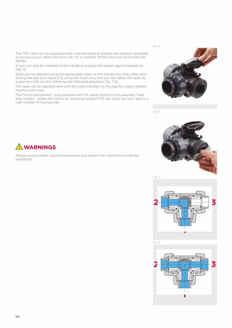
Fig. 5
WARNINGS
The TKD valve can be equipped with a handle block to prevent ball rotation (available as an accessory). When the block (16, 17) is installed, lift the lever (17) and rotate the handle.A lock can also be installed on the handle to protect the system against tampering (fig. 4).Seals can be adjusted using the extractable insert on the handle (fig. 5-6). After posi-tioning the ball as in figure 7-8, using this insert as a tool you can adjust the seals by screwing in the carriers following the indicated sequence (fig. 7-8).The seals can be adjusted later with the valve installed on the pipe by simply tighten-ing the union nuts.This "micro adjustment", only possible with FIP valves thanks to the patented "Seat stop system", allows the seal to be recovered where PTFE ball seats are worn due to a high number of manoeuvres.
Always avoid sudden closing manoeuvres and protect the valve from accidental operations.
Fig. 8
Fig. 7
Fig. 6
1
1
2
2
3
3
96

97

VXE DN 10÷50PVC-C
Easyfit 2-way ball valve
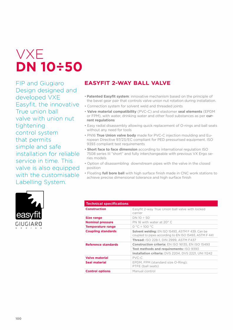
100
Technical specificationsConstruction Easyfit 2-way True Union ball valve with locked
carrierSize range DN 10 ÷ 50Nominal pressure PN 16 with water at 20° CTemperature range 0 °C ÷ 100 °CCoupling standards Solvent welding: EN ISO 15493, ASTM F 439. Can be
coupled to pipes according to EN ISO 15493, ASTM F 441Thread: ISO 228-1, DIN 2999, ASTM F437
Reference standards Construction criteria: EN ISO 16135, EN ISO 15493Test methods and requirements: ISO 9393Installation criteria: DVS 2204, DVS 2221, UNI 11242
Valve material PVC-CSeal material EPDM, FPM (standard size O-Ring);
PTFE (ball seats)
Control options Manual control
VXE
FIP and Giugiaro Design designed anddeveloped VXE Easyfit, the innovative True union ball valve with union nut tightening control system that permitssimple and safe installation for reliable service in time. This valve is also equipped with the customisable Labelling System.
EASYFIT 2-WAY BALL VALVE
• Patented Easyfit system: innovative mechanism based on the principle of the bevel gear pair that controls valve union nut rotation during installation.
• Connection system for solvent weld and threaded joints• Valve material compatibility (PVC-C) and elastomer seal elements (EPDM
or FPM), with water, drinking water and other food substances as per cur-rent regulations
• Easy radial disassembly allowing quick replacement of O-rings and ball seats without any need for tools
• PN16 True Union valve body made for PVC-C injection moulding and Eu-ropean Directive 97/23/EC compliant for PED pressurised equipment. ISO 9393 compliant test requirements
• Short face to face dimension according to international regulation ISO 7508 series III ”short” and fully interchangeable with previous VX Ergo se-ries models
• Option of disassembling downstream pipes with the valve in the closed position
• Floating full bore ball with high surface finish made in CNC work stations to achieve precise dimensional tolerance and high surface finish
DN 10÷50
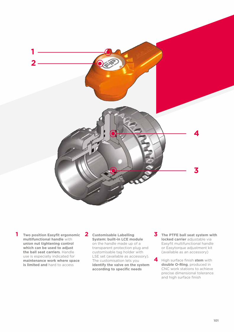
101
1 Two position Easyfit ergonomic multifunctional handle with union nut tightening control which can be used to adjust the ball seat carriers. Handle use is especially indicated for maintenance work where space is limited and hard to access
2 Customisable Labelling System: built-in LCE module on the handle made up of a transparent protection plug and customisable tag holder with LSE set (available as accessory). The customisation lets you identify the valve on the system according to specific needs
3 The PTFE ball seat system with locked carrier adjustable via Easyfit multifunctional handle or Easytorque adjustment kit (available as an accessory)
4 High surface finish stem with double O-Ring, produced in CNC work stations to achieve precise dimensional tolerance and high surface finish
21
4
3
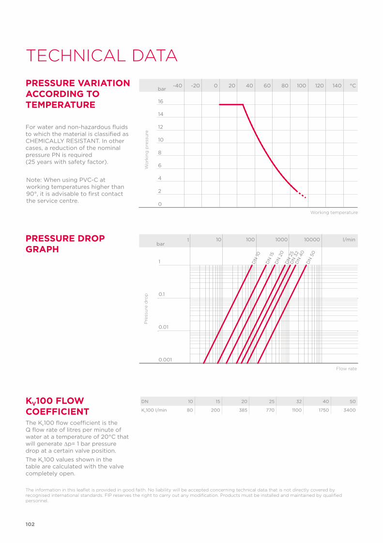
Note: When using PVC-C at working temperatures higher than 90°, it is advisable to first contact the service centre.
102
TECHNICAL DATA
-40 -20 0 20 40 60 80 100 120 140 °C
16
14
12
10
8
6
4
2
0
Wo
rkin
g p
ress
ure
Working temperature
barPRESSURE VARIATION ACCORDING TO TEMPERATURE
For water and non-hazardous fluids to which the material is classified as CHEMICALLY RESISTANT. In other cases, a reduction of the nominal pressure PN is required (25 years with safety factor).
The information in this leaflet is provided in good faith. No liability will be accepted concerning technical data that is not directly covered by recognised international standards. FIP reserves the right to carry out any modification. Products must be installed and maintained by qualified personnel.
PRESSURE DROP GRAPH
Pre
ssu
re d
rop
Flow rate
bar1 10 100 1000 10000 l/min
1
0.1
0.01
0.001
DN
15
DN
10
DN
20
DN
25
DN
32
DN
40
DN
50
KV100 FLOW COEFFICIENTThe Kv100 flow coefficient is the Q flow rate of litres per minute of water at a temperature of 20°C that will generate ∆p= 1 bar pressure drop at a certain valve position.The Kv100 values shown in the table are calculated with the valve completely open.
DN 10 15 20 25 32 40 50
Kv100 l/min 80 200 385 770 1100 1750 3400
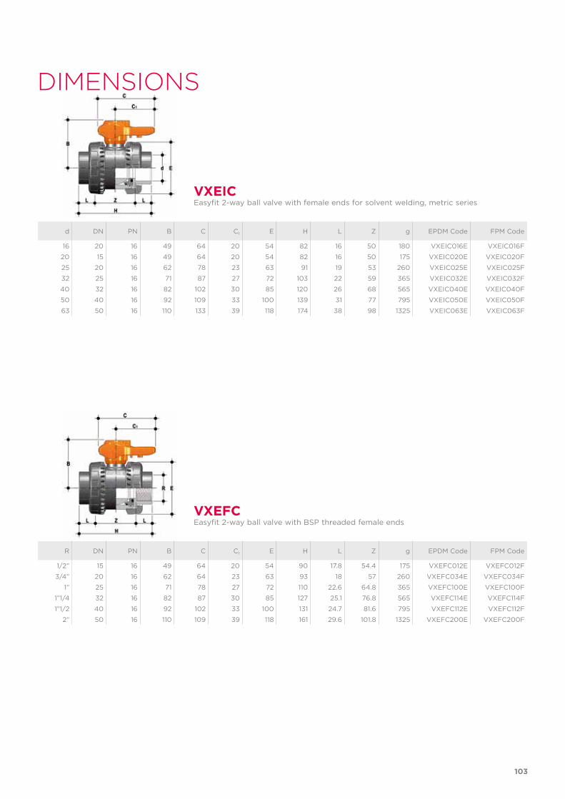
103
d DN PN B C C1 E H L Z g EPDM Code FPM Code
16 20 16 49 64 20 54 82 16 50 180 VXEIC016E VXEIC016F
20 15 16 49 64 20 54 82 16 50 175 VXEIC020E VXEIC020F
25 20 16 62 78 23 63 91 19 53 260 VXEIC025E VXEIC025F
32 25 16 71 87 27 72 103 22 59 365 VXEIC032E VXEIC032F
40 32 16 82 102 30 85 120 26 68 565 VXEIC040E VXEIC040F
50 40 16 92 109 33 100 139 31 77 795 VXEIC050E VXEIC050F
63 50 16 110 133 39 118 174 38 98 1325 VXEIC063E VXEIC063F
R DN PN B C C1 E H L Z g EPDM Code FPM Code
1/2” 15 16 49 64 20 54 90 17.8 54.4 175 VXEFC012E VXEFC012F
3/4” 20 16 62 64 23 63 93 18 57 260 VXEFC034E VXEFC034F
1” 25 16 71 78 27 72 110 22.6 64.8 365 VXEFC100E VXEFC100F
1”1/4 32 16 82 87 30 85 127 25.1 76.8 565 VXEFC114E VXEFC114F
1”1/2 40 16 92 102 33 100 131 24.7 81.6 795 VXEFC112E VXEFC112F
2” 50 16 110 109 39 118 161 29.6 101.8 1325 VXEFC200E VXEFC200F
VXEIC
VXEFC
Easyfit 2-way ball valve with female ends for solvent welding, metric series
Easyfit 2-way ball valve with BSP threaded female ends
DIMENSIONS
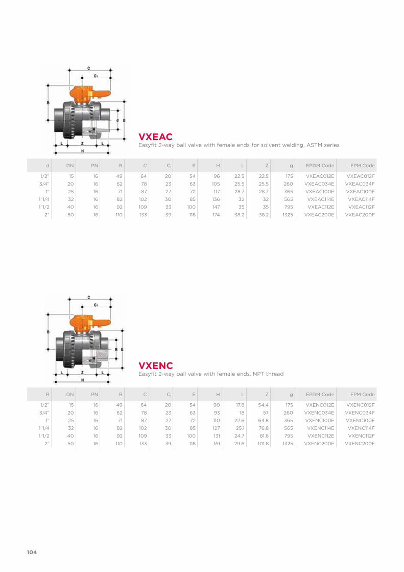
R DN PN B C C1 E H L Z g EPDM Code FPM Code
1/2” 15 16 49 64 20 54 90 17.8 54.4 175 VXENC012E VXENC012F
3/4” 20 16 62 78 23 63 93 18 57 260 VXENC034E VXENC034F
1” 25 16 71 87 27 72 110 22.6 64.8 365 VXENC100E VXENC100F
1”1/4 32 16 82 102 30 85 127 25.1 76.8 565 VXENC114E VXENC114F
1”1/2 40 16 92 109 33 100 131 24.7 81.6 795 VXENC112E VXENC112F
2” 50 16 110 133 39 118 161 29.6 101.8 1325 VXENC200E VXENC200F
VXENCEasyfit 2-way ball valve with female ends, NPT thread
104
d DN PN B C C1 E H L Z g EPDM Code FPM Code
1/2” 15 16 49 64 20 54 96 22.5 22.5 175 VXEAC012E VXEAC012F
3/4” 20 16 62 78 23 63 105 25.5 25.5 260 VXEAC034E VXEAC034F
1” 25 16 71 87 27 72 117 28.7 28.7 365 VXEAC100E VXEAC100F
1”1/4 32 16 82 102 30 85 136 32 32 565 VXEAC114E VXEAC114F
1”1/2 40 16 92 109 33 100 147 35 35 795 VXEAC112E VXEAC112F
2” 50 16 110 133 39 118 174 38.2 38.2 1325 VXEAC200E VXEAC200F
VXEACEasyfit 2-way ball valve with female ends for solvent welding, ASTM series
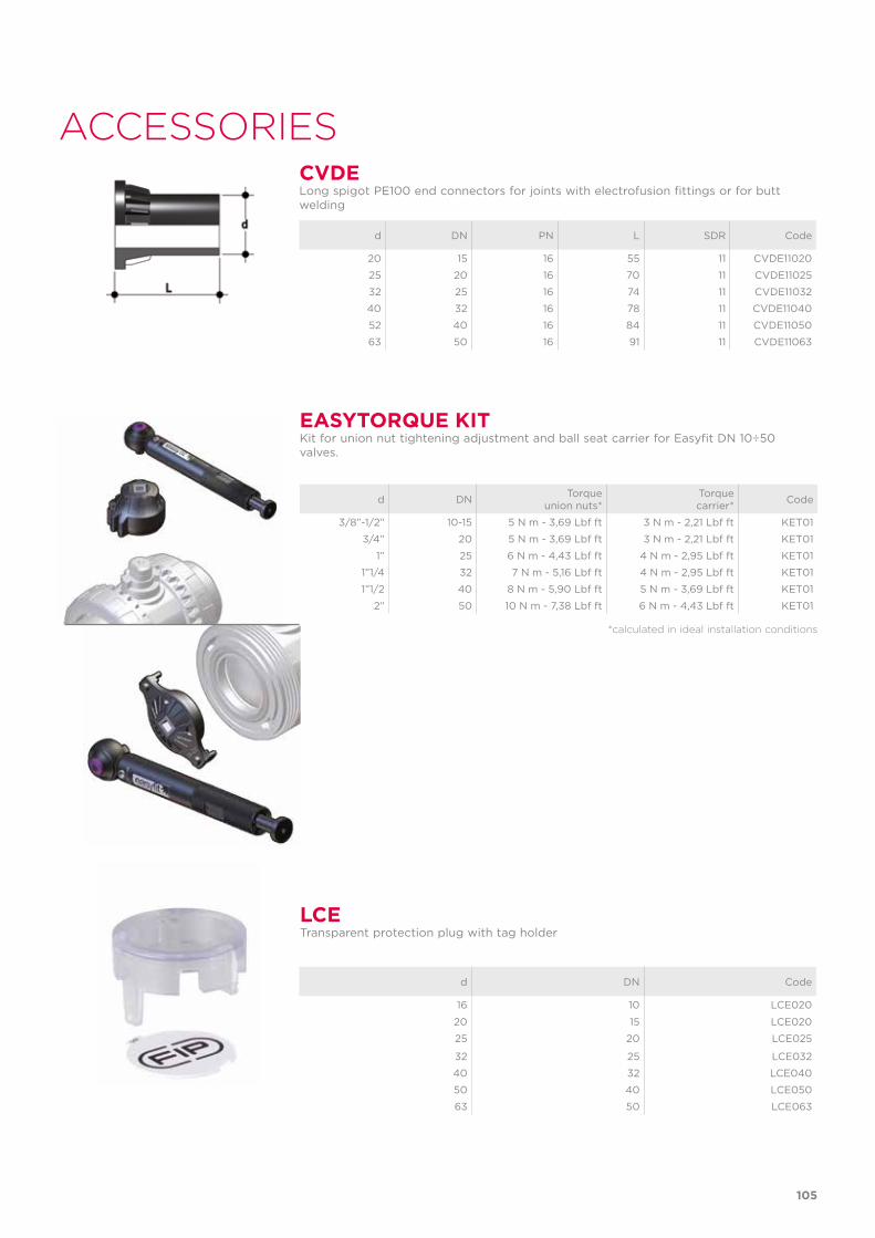
LCETransparent protection plug with tag holder
d DN Code
16 10 LCE020
20 15 LCE020
25 20 LCE025
32 25 LCE032
40 32 LCE040
50 40 LCE050
63 50 LCE063
ACCESSORIES
d DN PN L SDR Code
20 15 16 55 11 CVDE11020
25 20 16 70 11 CVDE11025
32 25 16 74 11 CVDE11032
40 32 16 78 11 CVDE11040
52 40 16 84 11 CVDE11050
63 50 16 91 11 CVDE11063
CVDELong spigot PE100 end connectors for joints with electrofusion fittings or for butt welding
EASYTORQUE KITKit for union nut tightening adjustment and ball seat carrier for Easyfit DN 10÷50 valves.
d DN Torque union nuts*
Torque carrier* Code
3/8”-1/2” 10-15 5 N m - 3,69 Lbf ft 3 N m - 2,21 Lbf ft KET01
3/4” 20 5 N m - 3,69 Lbf ft 3 N m - 2,21 Lbf ft KET01
1” 25 6 N m - 4,43 Lbf ft 4 N m - 2,95 Lbf ft KET01
1”1/4 32 7 N m - 5,16 Lbf ft 4 N m - 2,95 Lbf ft KET01
1”1/2 40 8 N m - 5,90 Lbf ft 5 N m - 3,69 Lbf ft KET01
2” 50 10 N m - 7,38 Lbf ft 6 N m - 4,43 Lbf ft KET01
*calculated in ideal installation conditions
105
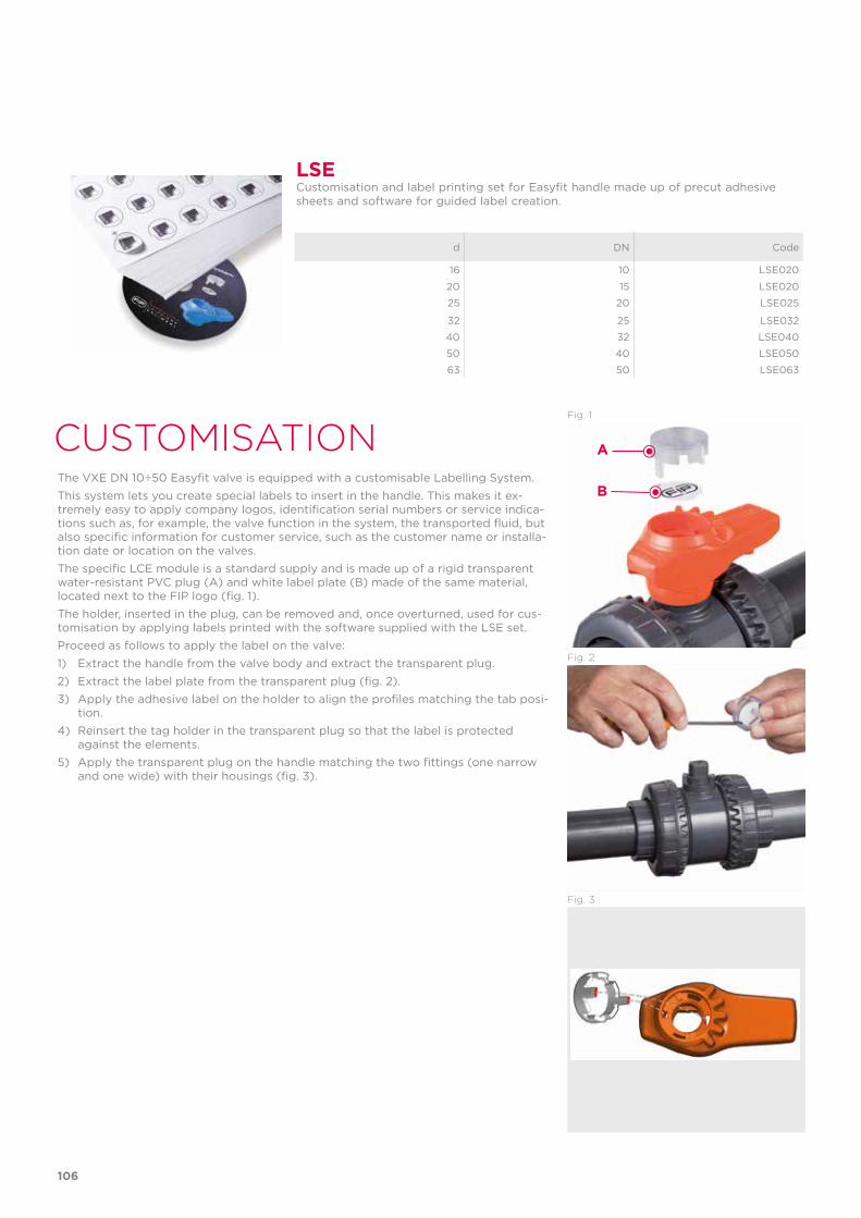
CUSTOMISATION
LSECustomisation and label printing set for Easyfit handle made up of precut adhesive sheets and software for guided label creation.
The VXE DN 10÷50 Easyfit valve is equipped with a customisable Labelling System. This system lets you create special labels to insert in the handle. This makes it ex-tremely easy to apply company logos, identification serial numbers or service indica-tions such as, for example, the valve function in the system, the transported fluid, but also specific information for customer service, such as the customer name or installa-tion date or location on the valves.The specific LCE module is a standard supply and is made up of a rigid transparent water-resistant PVC plug (A) and white label plate (B) made of the same material, located next to the FIP logo (fig. 1). The holder, inserted in the plug, can be removed and, once overturned, used for cus-tomisation by applying labels printed with the software supplied with the LSE set.Proceed as follows to apply the label on the valve:1) Extract the handle from the valve body and extract the transparent plug.2) Extract the label plate from the transparent plug (fig. 2).3) Apply the adhesive label on the holder to align the profiles matching the tab posi-
tion.4) Reinsert the tag holder in the transparent plug so that the label is protected
against the elements.5) Apply the transparent plug on the handle matching the two fittings (one narrow
and one wide) with their housings (fig. 3).
d DN Code
16 10 LSE020
20 15 LSE020
25 20 LSE025
32 25 LSE032
40 32 LSE040
50 40 LSE050
63 50 LSE063
Fig. 1
Fig. 2
Fig. 3
A
B
106
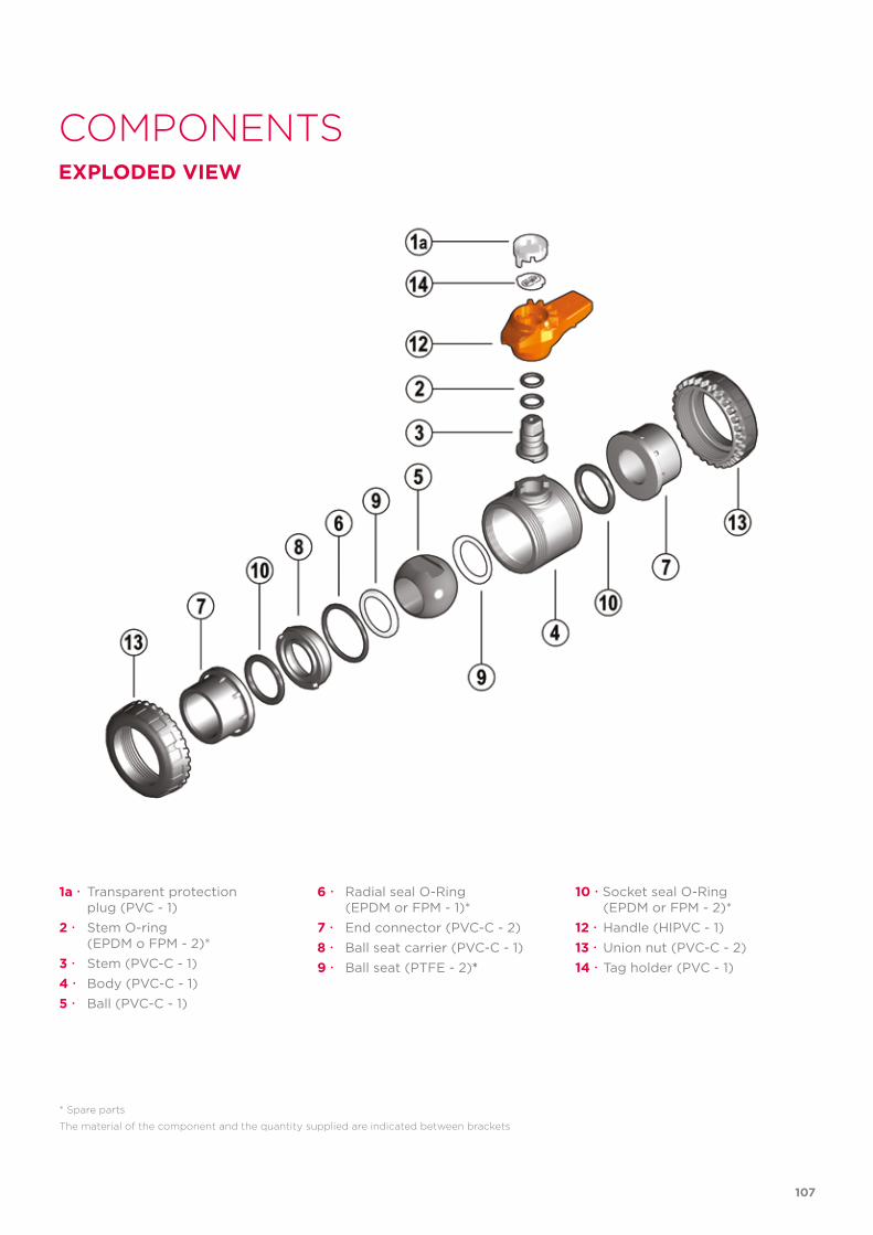
COMPONENTSEXPLODED VIEW
1a Transparent protection plug (PVC - 1)2 Stem O-ring (EPDM o FPM - 2)*3 Stem (PVC-C - 1)4 Body (PVC-C - 1) 5 Ball (PVC-C - 1)
* Spare parts
The material of the component and the quantity supplied are indicated between brackets
6 Radial seal O-Ring (EPDM or FPM - 1)*7 End connector (PVC-C - 2)8 Ball seat carrier (PVC-C - 1)9 Ball seat (PTFE - 2)*
10 Socket seal O-Ring (EPDM or FPM - 2)*12 Handle (HIPVC - 1)13 Union nut (PVC-C - 2)14 Tag holder (PVC - 1)
107
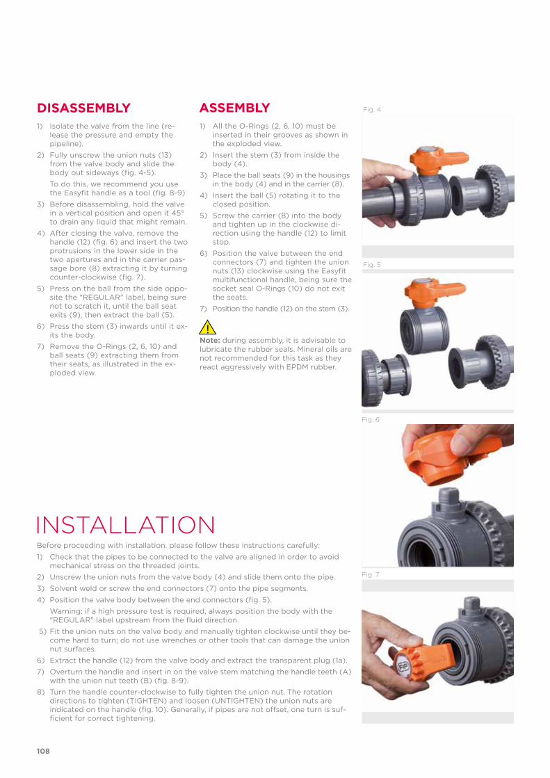
INSTALLATIONBefore proceeding with installation. please follow these instructions carefully:1) Check that the pipes to be connected to the valve are aligned in order to avoid
mechanical stress on the threaded joints.2) Unscrew the union nuts from the valve body (4) and slide them onto the pipe.3) Solvent weld or screw the end connectors (7) onto the pipe segments.4) Position the valve body between the end connectors (fig. 5). Warning: if a high pressure test is required, always position the body with the
"REGULAR" label upstream from the fluid direction. 5) Fit the union nuts on the valve body and manually tighten clockwise until they be-
come hard to turn; do not use wrenches or other tools that can damage the union nut surfaces.
6) Extract the handle (12) from the valve body and extract the transparent plug (1a).7) Overturn the handle and insert in on the valve stem matching the handle teeth (A)
with the union nut teeth (B) (fig. 8-9).8) Turn the handle counter-clockwise to fully tighten the union nut. The rotation
directions to tighten (TIGHTEN) and loosen (UNTIGHTEN) the union nuts are indicated on the handle (fig. 10). Generally, if pipes are not offset, one turn is suf-ficient for correct tightening.
DISASSEMBLY ASSEMBLY1) Isolate the valve from the line (re-
lease the pressure and empty the pipeline).
2) Fully unscrew the union nuts (13) from the valve body and slide the body out sideways (fig. 4-5).
To do this, we recommend you use the Easyfit handle as a tool (fig. 8-9)
3) Before disassembling, hold the valve in a vertical position and open it 45° to drain any liquid that might remain.
4) After closing the valve, remove the handle (12) (fig. 6) and insert the two protrusions in the lower side in the two apertures and in the carrier pas-sage bore (8) extracting it by turning counter-clockwise (fig. 7).
5) Press on the ball from the side oppo-site the "REGULAR" label, being sure not to scratch it, until the ball seat exits (9), then extract the ball (5).
6) Press the stem (3) inwards until it ex-its the body.
7) Remove the O-Rings (2, 6, 10) and ball seats (9) extracting them from their seats, as illustrated in the ex-ploded view.
1) All the O-Rings (2, 6, 10) must be inserted in their grooves as shown in the exploded view.
2) Insert the stem (3) from inside the body (4).
3) Place the ball seats (9) in the housings in the body (4) and in the carrier (8).
4) Insert the ball (5) rotating it to the closed position.
5) Screw the carrier (8) into the body and tighten up in the clockwise di-rection using the handle (12) to limit stop.
6) Position the valve between the end connectors (7) and tighten the union nuts (13) clockwise using the Easyfit multifunctional handle, being sure the socket seal O-Rings (10) do not exit the seats.
7) Position the handle (12) on the stem (3).
Note: during assembly, it is advisable to lubricate the rubber seals. Mineral oils are not recommended for this task as they react aggressively with EPDM rubber.
Fig. 5
Fig. 4
Fig. 6
Fig. 7
108
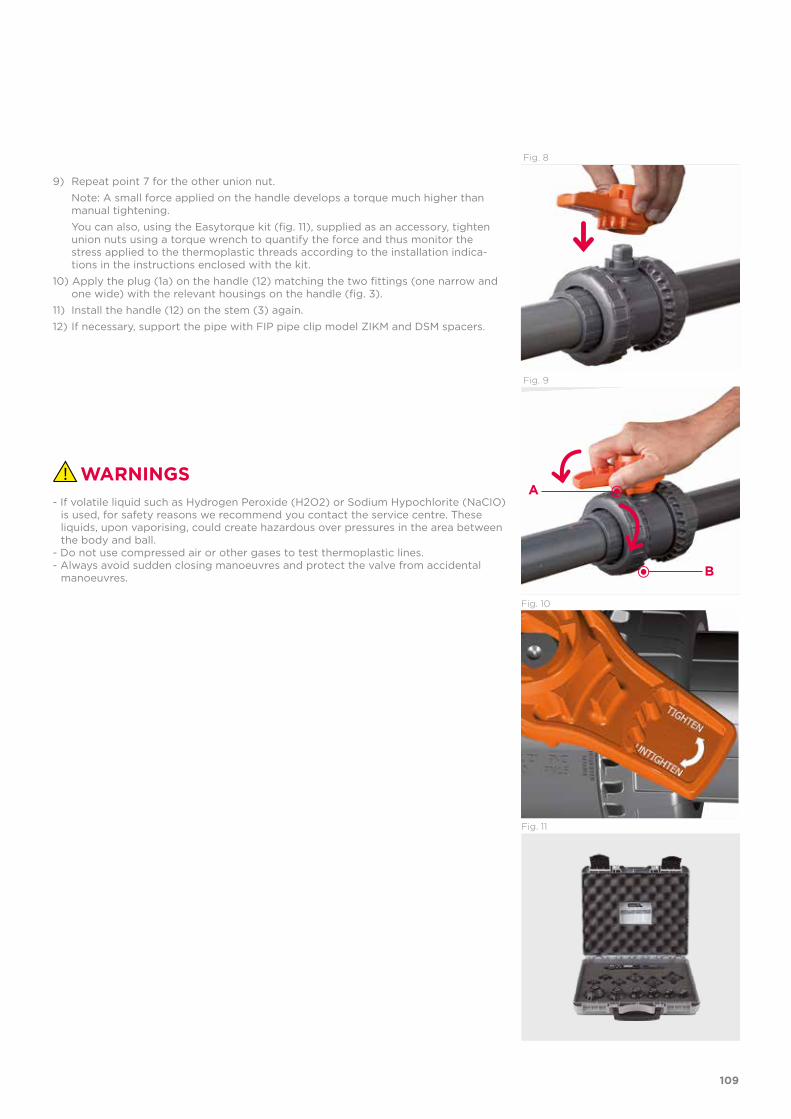
WARNINGS
9) Repeat point 7 for the other union nut. Note: A small force applied on the handle develops a torque much higher than
manual tightening. You can also, using the Easytorque kit (fig. 11), supplied as an accessory, tighten
union nuts using a torque wrench to quantify the force and thus monitor the stress applied to the thermoplastic threads according to the installation indica-tions in the instructions enclosed with the kit.
10) Apply the plug (1a) on the handle (12) matching the two fittings (one narrow and one wide) with the relevant housings on the handle (fig. 3).
11) Install the handle (12) on the stem (3) again.12) If necessary, support the pipe with FIP pipe clip model ZIKM and DSM spacers.
- If volatile liquid such as Hydrogen Peroxide (H2O2) or Sodium Hypochlorite (NaCIO) is used, for safety reasons we recommend you contact the service centre. These liquids, upon vaporising, could create hazardous over pressures in the area between the body and ball.
- Do not use compressed air or other gases to test thermoplastic lines.- Always avoid sudden closing manoeuvres and protect the valve from accidental
manoeuvres.
Fig. 10
Fig. 11
Fig. 8
Fig. 9
A
B
109

VXE DN 65÷100PVC-C
Easyfit 2-way ball valve
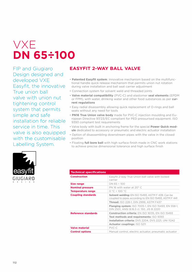
112
Technical specificationsConstruction Easyfit 2-way True Union ball valve with locked
carrierSize range DN 65 ÷ 100Nominal pressure PN 16 with water at 20° CTemperature range 0 °C ÷ 100 °CCoupling standards Solvent welding: EN ISO 15493, ASTM F 439. Can be
coupled to pipes according to EN ISO 15493, ASTM F 441Thread: ISO 228-1, DIN 2999, ASTM F437Flanging system: ISO 7005-1, EN ISO 15493, EN 558-1,DIN 2501, ANSI B.16.5 cl. 150, JIS B 2220
Reference standards Construction criteria: EN ISO 16135, EN ISO 15493Test methods and requirements: ISO 9393Installation criteria: DVS 2204, DVS 2221, UNI 11242Actuator couplings: ISO 5211
Valve material PVC-CControl options Manual control, electric actuator, pneumatic actuator
VXE
FIP and Giugiaro Design designed anddeveloped VXE Easyfit, the innovative True union ball valve with union nut tightening control system that permitssimple and safe installation for reliable service in time. This valve is also equipped with the customisable Labelling System.
EASYFIT 2-WAY BALL VALVE
• Patented Easyfit system: innovative mechanism based on the multifunc-tional handle quick release mechanism that permits union nut rotation during valve installation and ball seat carrier adjustment
• Connection system for solvent weld and threaded joints• Valve material compatibility (PVC-C) and elastomer seal elements (EPDM
or FPM), with water, drinking water and other food substances as per cur-rent regulations
• Easy radial disassembly allowing quick replacement of O-rings and ball seats without any need for tools
• PN16 True Union valve body made for PVC-C injection moulding and Eu-ropean Directive 97/23/EC compliant for PED pressurised equipment. ISO 9393 compliant test requirements
• Valve body with built in anchoring frame for the special Power Quick mod-ule dedicated to accessory or pneumatic and electric actuator installation
• Option of disassembling downstream pipes with the valve in the closed position
• Floating full bore ball with high surface finish made in CNC work stations to achieve precise dimensional tolerance and high surface finish
DN 65÷100
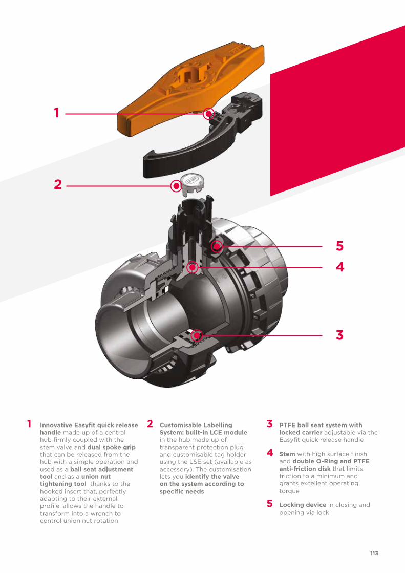
1
113
1 Innovative Easyfit quick release handle made up of a central hub firmly coupled with the stem valve and dual spoke grip that can be released from the hub with a simple operation and used as a ball seat adjustment tool and as a union nut tightening tool thanks to the hooked insert that, perfectly adapting to their external profile, allows the handle to transform into a wrench to control union nut rotation
2 Customisable Labelling System: built-in LCE module in the hub made up of transparent protection plug and customisable tag holder using the LSE set (available as accessory). The customisation lets you identify the valve on the system according to specific needs
3 PTFE ball seat system with locked carrier adjustable via the Easyfit quick release handle
4 Stem with high surface finish and double O-Ring and PTFE anti-friction disk that limits friction to a minimum and grants excellent operating torque
5 Locking device in closing and opening via lock
2
3
45
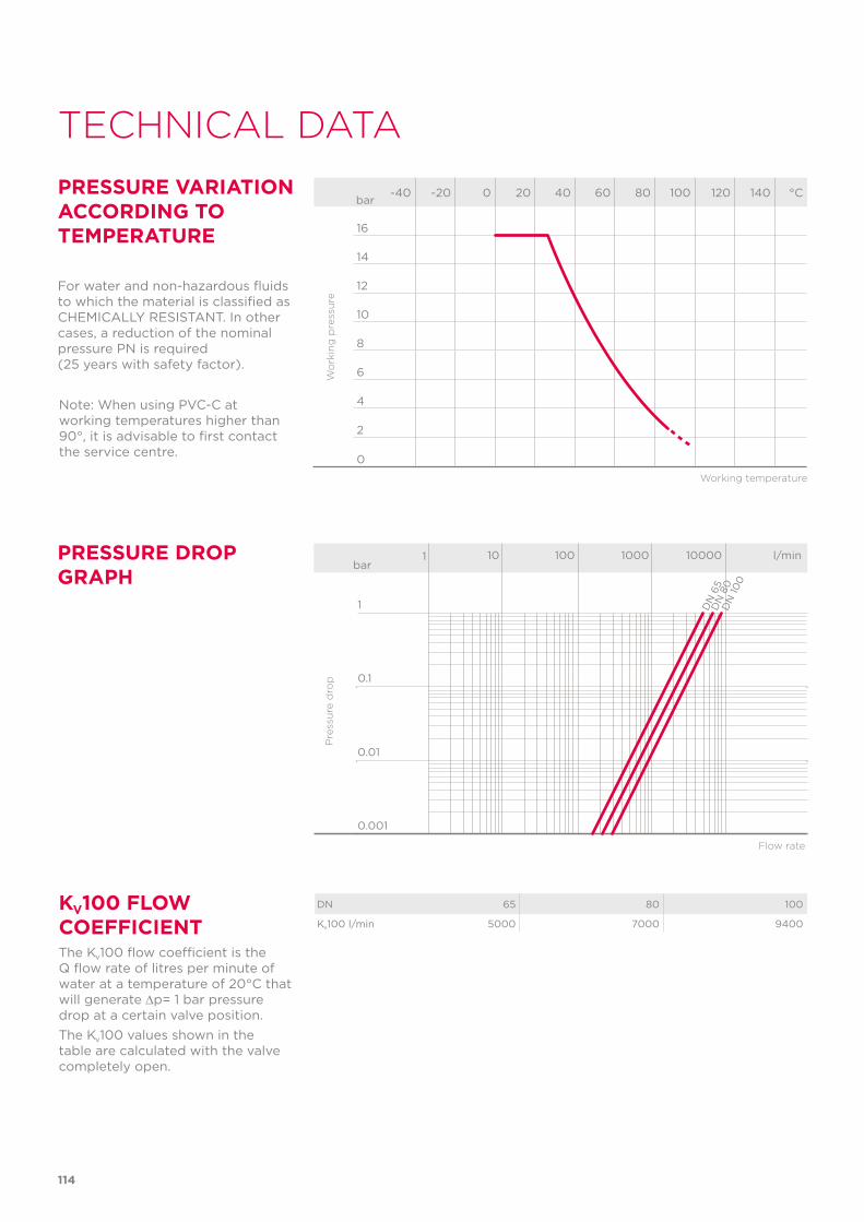
Note: When using PVC-C at working temperatures higher than 90°, it is advisable to first contact the service centre.
114
TECHNICAL DATA
-40 -20 0 20 40 60 80 100 120 140 °C
16
14
12
10
8
6
4
2
0
Wo
rkin
g p
ress
ure
Working temperature
barPRESSURE VARIATION ACCORDING TO TEMPERATURE
For water and non-hazardous fluids to which the material is classified as CHEMICALLY RESISTANT. In other cases, a reduction of the nominal pressure PN is required (25 years with safety factor).
KV100 FLOW COEFFICIENTThe Kv100 flow coefficient is the Q flow rate of litres per minute of water at a temperature of 20°C that will generate ∆p= 1 bar pressure drop at a certain valve position.The Kv100 values shown in the table are calculated with the valve completely open.
PRESSURE DROP GRAPH
Pre
ssu
re d
rop
Flow rate
bar1 10 100 1000 10000 l/min
1
0.1
0.01
0.001
DN
65
DN
80
DN
100
DN 65 80 100
Kv100 l/min 5000 7000 9400
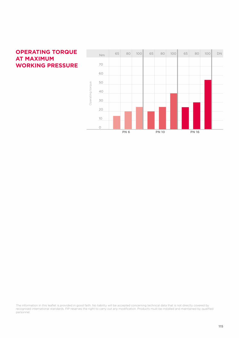
OPERATING TORQUE AT MAXIMUM WORKING PRESSURE
Nm 65 80 100 65 80 100 65 80 100 DN
70
60
50
40
30
20
10
0
Op
erat
ing
to
rqu
e
PN 6 PN 10 PN 16
115
The information in this leaflet is provided in good faith. No liability will be accepted concerning technical data that is not directly covered by recognised international standards. FIP reserves the right to carry out any modification. Products must be installed and maintained by qualified personnel.
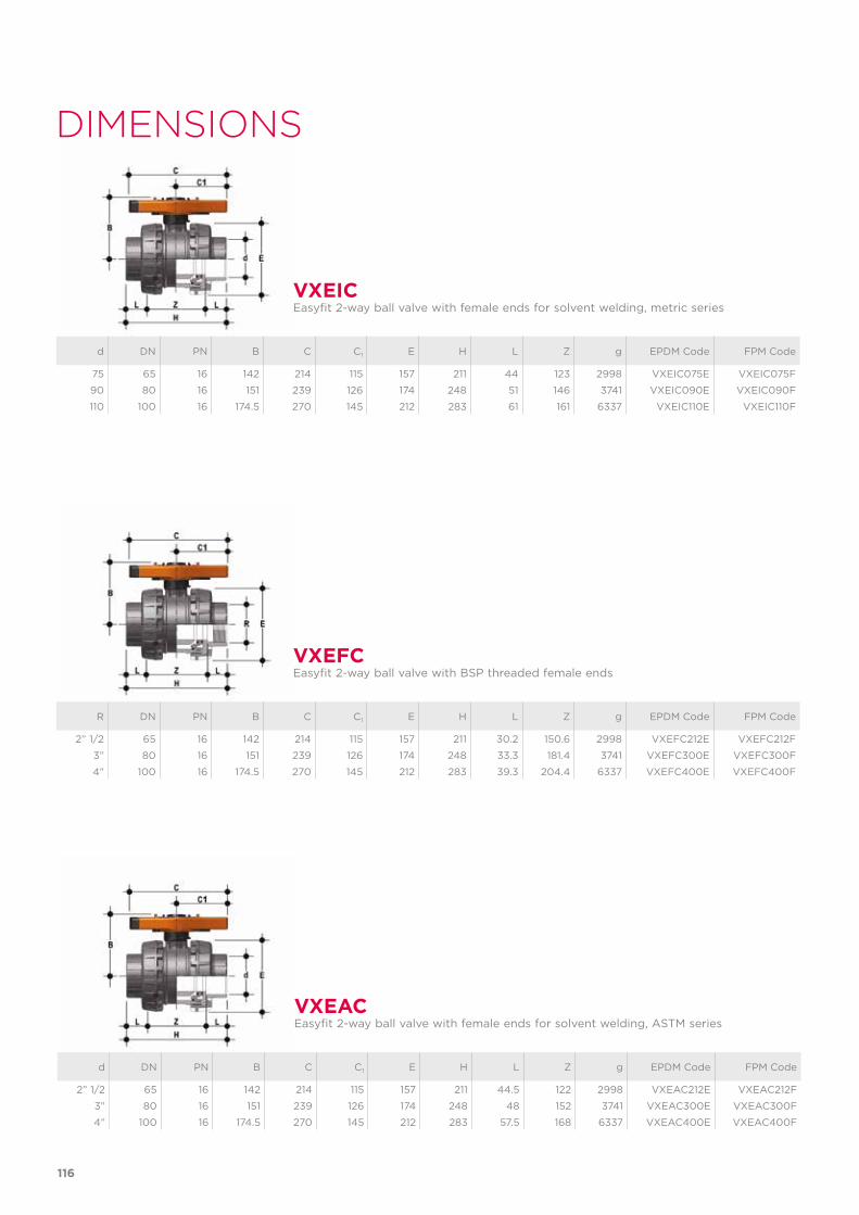
d DN PN B C C1 E H L Z g EPDM Code FPM Code
2” 1/2 65 16 142 214 115 157 211 44.5 122 2998 VXEAC212E VXEAC212F
3” 80 16 151 239 126 174 248 48 152 3741 VXEAC300E VXEAC300F
4” 100 16 174.5 270 145 212 283 57.5 168 6337 VXEAC400E VXEAC400F
VXEACEasyfit 2-way ball valve with female ends for solvent welding, ASTM series
DIMENSIONS
d DN PN B C C1 E H L Z g EPDM Code FPM Code
75 65 16 142 214 115 157 211 44 123 2998 VXEIC075E VXEIC075F
90 80 16 151 239 126 174 248 51 146 3741 VXEIC090E VXEIC090F
110 100 16 174.5 270 145 212 283 61 161 6337 VXEIC110E VXEIC110F
R DN PN B C C1 E H L Z g EPDM Code FPM Code
2” 1/2 65 16 142 214 115 157 211 30.2 150.6 2998 VXEFC212E VXEFC212F
3” 80 16 151 239 126 174 248 33.3 181.4 3741 VXEFC300E VXEFC300F
4” 100 16 174.5 270 145 212 283 39.3 204.4 6337 VXEFC400E VXEFC400F
VXEIC
VXEFC
Easyfit 2-way ball valve with female ends for solvent welding, metric series
Easyfit 2-way ball valve with BSP threaded female ends
116
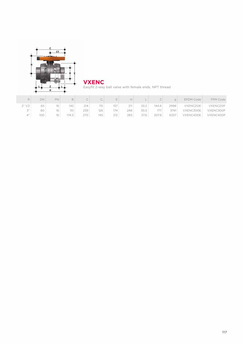
R DN PN B C C1 E H L Z g EPDM Code FPM Code
2” 1/2 65 16 142 214 115 157 211 33.2 144.6 2998 VXENC212E VXENC212F
3” 80 16 151 239 126 174 248 35.5 177 3741 VXENC300E VXENC300F
4” 100 16 174.5 270 145 212 283 37.6 207.8 6337 VXENC400E VXENC400F
VXENCEasyfit 2-way ball valve with female ends, NPT thread
117
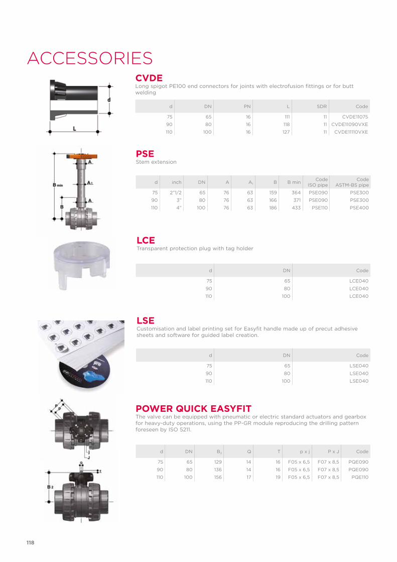
LSE
LCE
Customisation and label printing set for Easyfit handle made up of precut adhesive sheets and software for guided label creation.
Transparent protection plug with tag holder
d inch DN A A1 B B min CodeISO pipe
CodeASTM-BS pipe
75 2”1/2 65 76 63 159 364 PSE090 PSE300
90 3” 80 76 63 166 371 PSE090 PSE300
110 4” 100 76 63 186 433 PSE110 PSE400
PSEStem extension
d DN Code
75 65 LSE040
90 80 LSE040
110 100 LSE040
d DN Code
75 65 LCE040
90 80 LCE040
110 100 LCE040
POWER QUICK EASYFITThe valve can be equipped with pneumatic or electric standard actuators and gearbox for heavy-duty operations, using the PP-GR module reproducing the drilling pattern foreseen by ISO 5211.
d DN B2 Q T p x j P x J Code
75 65 129 14 16 F05 x 6,5 F07 x 8,5 PQE090
90 80 136 14 16 F05 x 6,5 F07 x 8,5 PQE090
110 100 156 17 19 F05 x 6,5 F07 x 8,5 PQE110
ACCESSORIES
d DN PN L SDR Code
75 65 16 111 11 CVDE11075
90 80 16 118 11 CVDE11090VXE
110 100 16 127 11 CVDE11110VXE
CVDELong spigot PE100 end connectors for joints with electrofusion fittings or for butt welding
118
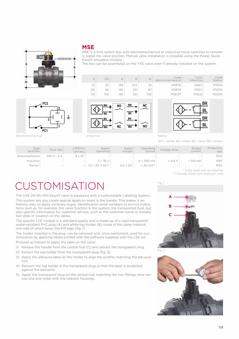
CUSTOMISATIONThe VXE DN 65÷100 Easyfit valve is equipped with a customisable Labelling System. This system lets you create special labels to insert in the handle. This makes it ex-tremely easy to apply company logos, identification serial numbers or service indica-tions such as, for example, the valve function in the system, the transported fluid, but also specific information for customer service, such as the customer name or installa-tion date or location on the valves. The specific LCE module is a standard supply and is made up of a rigid transparent water-resistant PVC plug (A) and white tag holder (B) made of the same material, one side of which bears the FIP logo (fig. 1). The holder, inserted in the plug, can be removed and, once overturned, used for cus-tomisation by applying labels printed with the software supplied with the LSE set.Proceed as follows to apply the label on the valve:1) Release the handle from the central hub (C) and extract the transparent plug.2) Extract the tag holder from the transparent plug (fig. 2).3) Apply the adhesive label on the holder to align the profiles matching the tab posi-
tion.4) Reinsert the tag holder in the transparent plug so that the label is protected
against the elements.5) Apply the transparent plug on the central hub matching the two fittings (one nar-
row and one wide) with the relevant housings.
Fig. 1
Fig. 2
Type switches Flow rate Lifetime
[drives]Rated
operatingRated
voltageOperating
current Voltage drop Empty current
Protection rate
Electromechanical 250 V - 5 A 3 x 10⁷ - - - - - IP65
Inductive - - 5 ÷ 36 V - 4 ÷ 200 mA < 4,6 V < 0,8 mA IP65
Namur* - - 7,5 ÷ 30 V DC** 8,2 V DC < 30 mA** - - IP65
* To be used with an amplifier** Outside areas with explosion risks
Electromechanical Inductive Namur
WH = white; BK = black; BL = blue; BR = brown
MSEMSE is a limit switch box with electromechanical or inductive micro switches to remote-ly signal the valve position. Manual valve installation is possible using the Power Quick Easyfit actuation module.The box can be assembled on the VXE valve even if already installed on the system.
d DN A B B1Code
electromechanicalCode
inductiveCode
Namur
75 65 139 203 79 MSE1M MSE1I MSE1N
90 80 146 210 87 MSE1M MSE1I MSE1N
110 100 166 231 106 MSE2M MSE2I MSE2N
A
B
C
119

COMPONENTSEXPLODED VIEW
1 Easyfit multifunctional handle insert hooked(PP-GR - 1)2 Easyfit multifunctional handle (HIPVC - 1)3 Stem O-Ring (EPDM or FPM - 2)*4 Stem (PVC-C - 1) 5 Ball seat (PTFE - 2)*6 Ball (PVC-C - 1)*7 Body (PVC-C - 1)
* Spare parts
The material of the component and the quantity supplied are indicated between brackets
8 Ball seat O-Ring (EPDM or FPM - 2)*9 Radial seal O-Ring (EPDM or FPM - 1)*10 Socket seal O-Ring (EPDM or FPM - 2)*11 Ball seat carrier (PVC-C - 1)12 End connector (PVC-C - 2)13 Union nut(PVC-C - 2)14 Transparent protection plug (PVC - 1)
15 Central hub (HIPVC - 1)16 Anti-friction disk (PTFE - 1)*17 Tag holder (PVC-U - 1)18 Locking device plate (HIPVC - 1)19 Self-threading screw (STAINLESS steel - 2)
120
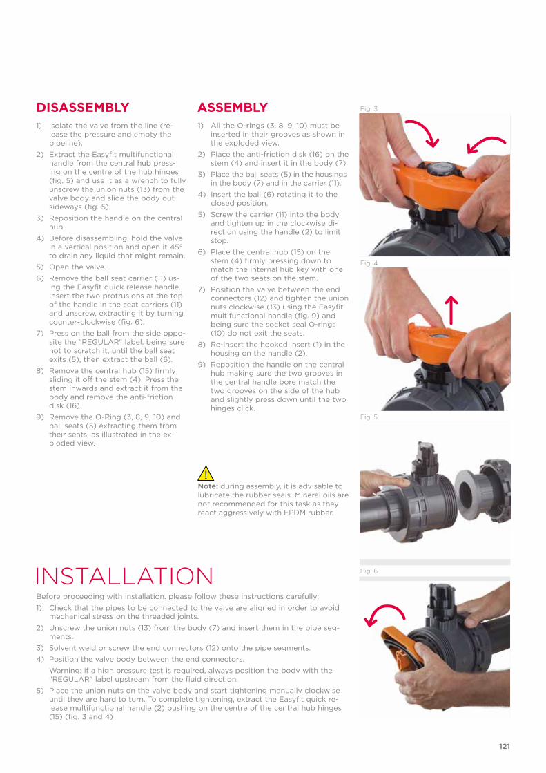
INSTALLATIONBefore proceeding with installation. please follow these instructions carefully:1) Check that the pipes to be connected to the valve are aligned in order to avoid
mechanical stress on the threaded joints.2) Unscrew the union nuts (13) from the body (7) and insert them in the pipe seg-
ments.3) Solvent weld or screw the end connectors (12) onto the pipe segments.4) Position the valve body between the end connectors. Warning: if a high pressure test is required, always position the body with the
"REGULAR" label upstream from the fluid direction.5) Place the union nuts on the valve body and start tightening manually clockwise
until they are hard to turn. To complete tightening, extract the Easyfit quick re-lease multifunctional handle (2) pushing on the centre of the central hub hinges (15) (fig. 3 and 4)
DISASSEMBLY ASSEMBLY1) Isolate the valve from the line (re-
lease the pressure and empty the pipeline).
2) Extract the Easyfit multifunctional handle from the central hub press-ing on the centre of the hub hinges (fig. 5) and use it as a wrench to fully unscrew the union nuts (13) from the valve body and slide the body out sideways (fig. 5).
3) Reposition the handle on the central hub.
4) Before disassembling, hold the valve in a vertical position and open it 45° to drain any liquid that might remain.
5) Open the valve. 6) Remove the ball seat carrier (11) us-
ing the Easyfit quick release handle. Insert the two protrusions at the top of the handle in the seat carriers (11) and unscrew, extracting it by turning counter-clockwise (fig. 6).
7) Press on the ball from the side oppo-site the "REGULAR" label, being sure not to scratch it, until the ball seat exits (5), then extract the ball (6).
8) Remove the central hub (15) firmly sliding it off the stem (4). Press the stem inwards and extract it from the body and remove the anti-friction disk (16).
9) Remove the O-Ring (3, 8, 9, 10) and ball seats (5) extracting them from their seats, as illustrated in the ex-ploded view.
1) All the O-rings (3, 8, 9, 10) must be inserted in their grooves as shown in the exploded view.
2) Place the anti-friction disk (16) on the stem (4) and insert it in the body (7).
3) Place the ball seats (5) in the housings in the body (7) and in the carrier (11).
4) Insert the ball (6) rotating it to the closed position.
5) Screw the carrier (11) into the body and tighten up in the clockwise di-rection using the handle (2) to limit stop.
6) Place the central hub (15) on the stem (4) firmly pressing down to match the internal hub key with one of the two seats on the stem.
7) Position the valve between the end connectors (12) and tighten the union nuts clockwise (13) using the Easyfit multifunctional handle (fig. 9) and being sure the socket seal O-rings (10) do not exit the seats.
8) Re-insert the hooked insert (1) in the housing on the handle (2).
9) Reposition the handle on the central hub making sure the two grooves in the central handle bore match the two grooves on the side of the hub and slightly press down until the two hinges click.
Fig. 5
Fig. 6
Fig. 4
Fig. 3
Note: during assembly, it is advisable to lubricate the rubber seals. Mineral oils are not recommended for this task as they react aggressively with EPDM rubber.
121
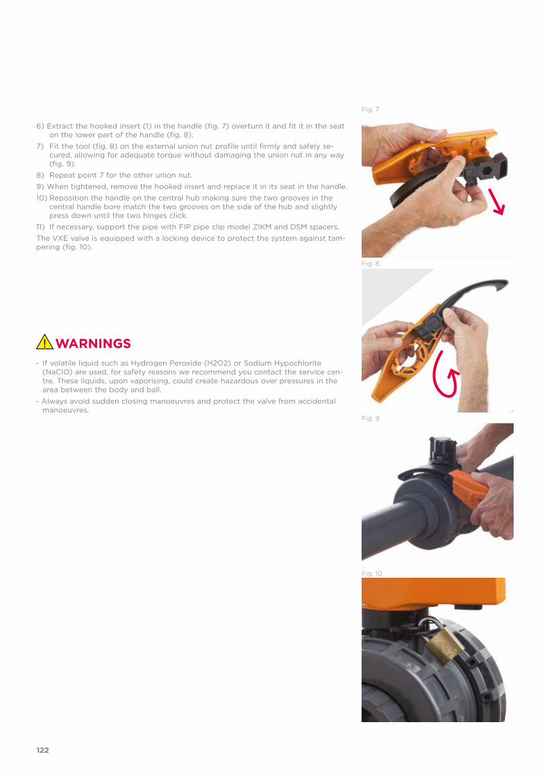
Fig. 8
Fig. 7
Fig. 10
Fig. 9
6) Extract the hooked insert (1) in the handle (fig. 7) overturn it and fit it in the seat on the lower part of the handle (fig. 8).
7) Fit the tool (fig. 8) on the external union nut profile until firmly and safely se-cured, allowing for adequate torque without damaging the union nut in any way (fig. 9).
8) Repeat point 7 for the other union nut.9) When tightened, remove the hooked insert and replace it in its seat in the handle.10) Reposition the handle on the central hub making sure the two grooves in the
central handle bore match the two grooves on the side of the hub and slightly press down until the two hinges click.
11) If necessary, support the pipe with FIP pipe clip model ZIKM and DSM spacers.The VXE valve is equipped with a locking device to protect the system against tam-pering (fig. 10).
WARNINGS- If volatile liquid such as Hydrogen Peroxide (H2O2) or Sodium Hypochlorite
(NaCIO) are used, for safety reasons we recommend you contact the service cen-tre. These liquids, upon vaporising, could create hazardous over pressures in the area between the body and ball.
- Always avoid sudden closing manoeuvres and protect the valve from accidental manoeuvres.
122

123

SXE DN 10÷50PVC-C
Easyfit True Union ball check valve
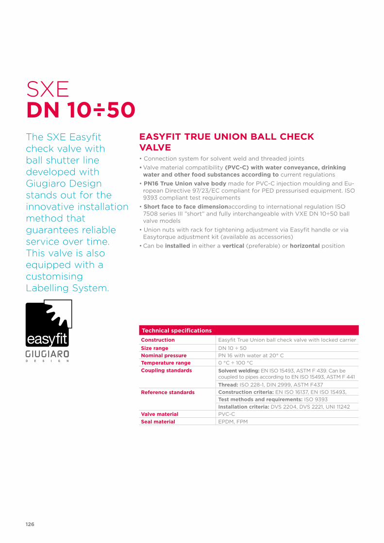
126
Technical specificationsConstruction Easyfit True Union ball check valve with locked carrier
Size range DN 10 ÷ 50Nominal pressure PN 16 with water at 20° CTemperature range 0 °C ÷ 100 °CCoupling standards Solvent welding: EN ISO 15493, ASTM F 439. Can be
coupled to pipes according to EN ISO 15493, ASTM F 441Thread: ISO 228-1, DIN 2999, ASTM F437
Reference standards Construction criteria: EN ISO 16137, EN ISO 15493,Test methods and requirements: ISO 9393Installation criteria: DVS 2204, DVS 2221, UNI 11242
Valve material PVC-CSeal material EPDM, FPM
SXE
The SXE Easyfit check valve with ball shutter line developed with Giugiaro Design stands out for the innovative installation method that guarantees reliable service over time.This valve is alsoequipped with acustomisingLabelling System.
EASYFIT TRUE UNION BALL CHECK VALVE• Connection system for solvent weld and threaded joints• Valve material compatibility (PVC-C) with water conveyance, drinking
water and other food substances according to current regulations• PN16 True Union valve body made for PVC-C injection moulding and Eu-
ropean Directive 97/23/EC compliant for PED pressurised equipment. ISO 9393 compliant test requirements
• Short face to face dimensionaccording to international regulation ISO 7508 series III ”short” and fully interchangeable with VXE DN 10÷50 ball valve models
• Union nuts with rack for tightening adjustment via Easyfit handle or via Easytorque adjustment kit (available as accessories)
• Can be installed in either a vertical (preferable) or horizontal position
DN 10÷50
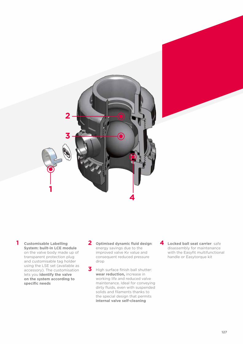
127
1 Customisable Labelling System: built-in LCE module on the valve body made up of transparent protection plug and customisable tag holder using the LSE set (available as accessory). The customisation lets you identify the valve on the system according to specific needs
2 Optimised dynamic fluid design: energy savings due to the improved valve Kv value and consequent reduced pressure drop
3 High surface finish ball shutter: wear reduction, increase in working life and reduced valve maintenance. Ideal for conveying dirty fluids, even with suspended solids and filaments thanks to the special design that permits internal valve self-cleaning
4 Locked ball seat carrier: safe disassembly for maintenance with the Easyfit multifunctional handle or Easytorque kit
2
3
41
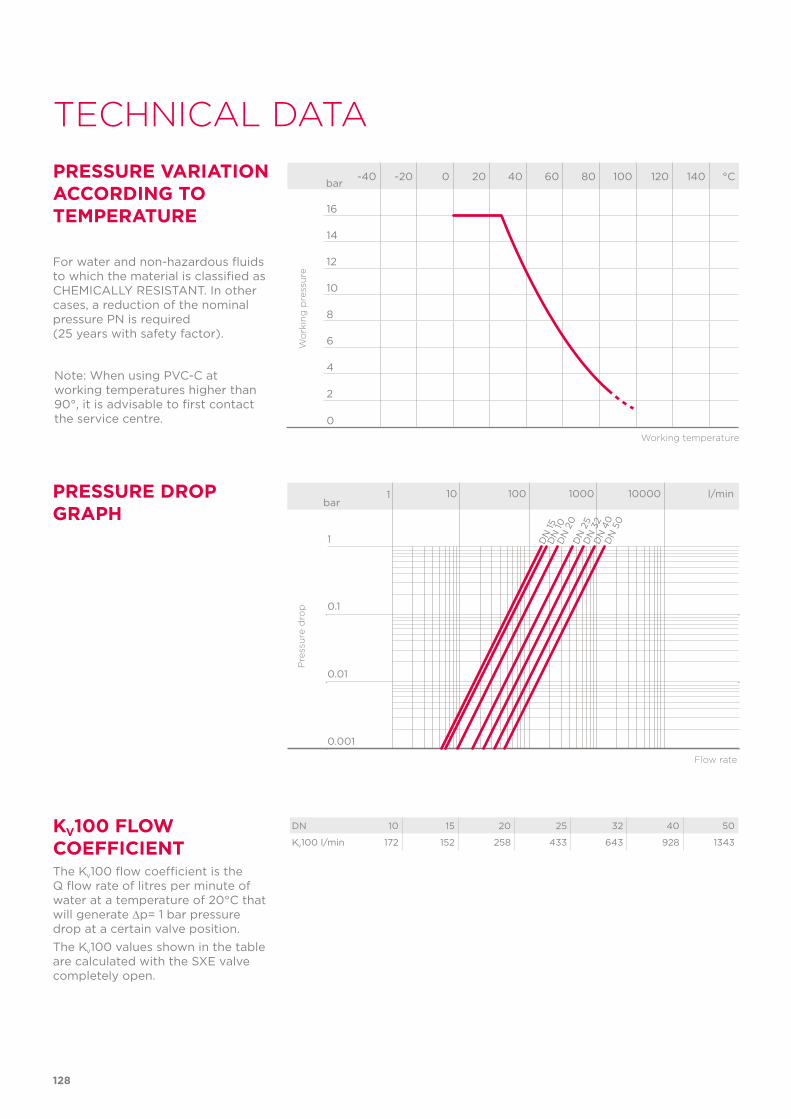
Note: When using PVC-C at working temperatures higher than 90°, it is advisable to first contact the service centre.
128
TECHNICAL DATA
-40 -20 0 20 40 60 80 100 120 140 °C
16
14
12
10
8
6
4
2
0
Wo
rkin
g p
ress
ure
Working temperature
barPRESSURE VARIATION ACCORDING TO TEMPERATURE
For water and non-hazardous fluids to which the material is classified as CHEMICALLY RESISTANT. In other cases, a reduction of the nominal pressure PN is required (25 years with safety factor).
PRESSURE DROP GRAPH
Pre
ssu
re d
rop
Flow rate
bar1 10 100 1000 10000 l/min
1
0.1
0.01
0.001
DN
15D
N 10
DN
20
DN
25
DN
32
DN
40
DN
50
KV100 FLOW COEFFICIENTThe Kv100 flow coefficient is the Q flow rate of litres per minute of water at a temperature of 20°C that will generate ∆p= 1 bar pressure drop at a certain valve position.The Kv100 values shown in the table are calculated with the SXE valve completely open.
DN 10 15 20 25 32 40 50
Kv100 l/min 172 152 258 433 643 928 1343
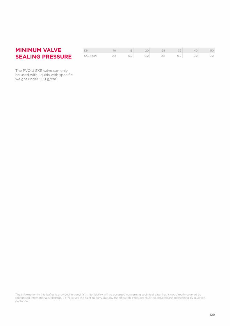
129
The information in this leaflet is provided in good faith. No liability will be accepted concerning technical data that is not directly covered by recognised international standards. FIP reserves the right to carry out any modification. Products must be installed and maintained by qualified personnel.
MINIMUM VALVE SEALING PRESSURE
The PVC-U SXE valve can only be used with liquids with specific weight under 1.50 g/cm3.
DN 10 15 20 25 32 40 50
SXE (bar) 0.2 0.2 0.2 0.2 0.2 0.2 0.2
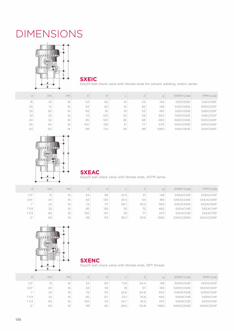
130
d DN PN E H L Z g EPDM Code FPM Code
16 10 16 54 82 14 54 145 SXEIC016E SXEIC016F
20 15 16 54 82 16 50 148 SXEIC020E SXEIC020F
25 20 16 63 91 19 53 190 SXEIC025E SXEIC025F
32 25 16 72 103 22 59 300 SXEIC032E SXEIC032F
40 32 16 85 120 26 68 460 SXEIC040E SXEIC040F
50 40 16 100 139 31 77 675 SXEIC050E SXEIC050F
63 50 16 118 174 38 98 1080 SXEIC063E SXEIC063F
SXEICEasyfit ball check valve with female ends for solvent welding, metric series
DIMENSIONS
d DN PN E H L Z g EPDM Code FPM Code
1/2” 15 16 54 96 22.5 51 148 SXEAC012E SXEAC012F
3/4” 20 16 63 105 25.5 54 190 SXEAC034E SXEAC034F
1” 25 16 72 117 28.7 59.5 300 SXEAC100E SXEAC100F
1”1/4 32 16 85 136 32 72 460 SXEAC114E SXEAC114F
1”1/2 40 16 100 147 35 77 675 SXEAC112E SXEAC112F
2” 50 16 118 174 38.2 97.6 1080 SXEAC200E SXEAC200F
R DN PN E H L Z g EPDM Code FPM Code
1/2” 15 16 54 90 17.8 54.4 148 SXENC012E SXENC012F
3/4” 20 16 63 93 18 57 190 SXENC034E SXENC034F
1” 25 16 72 110 22.6 64.8 300 SXENC100E SXENC100F
1”1/4 32 16 85 127 25.1 76.8 460 SXENC114E SXENC114F
1”1/2 40 16 100 131 24.7 81.6 675 SXENC112E SXENC112F
2” 50 16 118 161 29.6 101.8 1080 SXENC200E SXENC200F
SXEAC
SXENC
Easyfit ball check valve with female ends, ASTM series
Easyfit ball check valve with female ends, NPT thread

d DN PN L SDR Code
20 15 16 55 11 CVDE11020
25 20 16 70 11 CVDE11025
32 25 16 74 11 CVDE11032
40 32 16 78 11 CVDE11040
52 40 16 84 11 CVDE11050
63 50 16 91 11 CVDE11063
CVDELong spigot PE100 end connectors for joints with electrofusion fittings or for butt welding
d DN Code
16 - 20 10 - 15 HAVXE020
25 20 HAVXE025
32 25 HAVXE032
40 32 HAVXE040
52 40 HAVXE050
63 50 HAVXE063
EASYFIT HANDLE DN 10÷50Easyfit multifunctional handle for union nuts tightening SXE-SSE DN 10÷50
EASYTORQUE KITKit for union nut tightening adjustment and ball seat carrier for Easyfit DN 10÷50 valves.
d DN Torque union nuts*
Torque carrier* Code
3/8”-1/2” 10-15 5 N m - 3,69 Lbf ft 3 N m - 2,21 Lbf ft KET01
3/4” 20 5 N m - 3,69 Lbf ft 3 N m - 2,21 Lbf ft KET01
1” 25 6 N m - 4,43 Lbf ft 4 N m - 2,95 Lbf ft KET01
1”1/4 32 7 N m - 5,16 Lbf ft 4 N m - 2,95 Lbf ft KET01
1”1/2 40 8 N m - 5,90 Lbf ft 5 N m - 3,69 Lbf ft KET01
2” 50 10 N m - 7,38 Lbf ft 6 N m - 4,43 Lbf ft KET01
*calculated in ideal installation conditions
131
ACCESSORIES
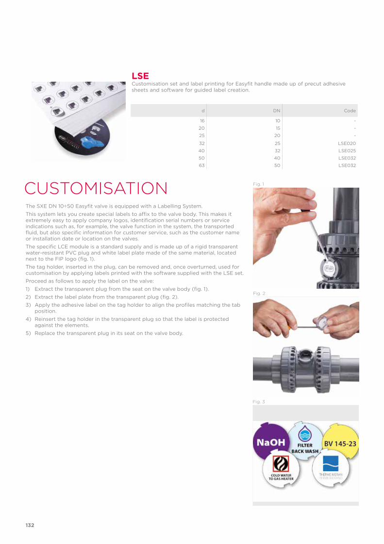
CUSTOMISATIONThe SXE DN 10÷50 Easyfit valve is equipped with a Labelling System. This system lets you create special labels to affix to the valve body. This makes it extremely easy to apply company logos, identification serial numbers or service indications such as, for example, the valve function in the system, the transported fluid, but also specific information for customer service, such as the customer name or installation date or location on the valves.The specific LCE module is a standard supply and is made up of a rigid transparent water-resistant PVC plug and white label plate made of the same material, located next to the FIP logo (fig. 1). The tag holder, inserted in the plug, can be removed and, once overturned, used for customisation by applying labels printed with the software supplied with the LSE set.Proceed as follows to apply the label on the valve:1) Extract the transparent plug from the seat on the valve body (fig. 1).2) Extract the label plate from the transparent plug (fig. 2).3) Apply the adhesive label on the tag holder to align the profiles matching the tab
position.4) Reinsert the tag holder in the transparent plug so that the label is protected
against the elements.5) Replace the transparent plug in its seat on the valve body.
LSECustomisation set and label printing for Easyfit handle made up of precut adhesive sheets and software for guided label creation.
d DN Code
16 10 -
20 15 -
25 20 -
32 25 LSE020
40 32 LSE025
50 40 LSE032
63 50 LSE032
Fig. 1
Fig. 2
Fig. 3
132
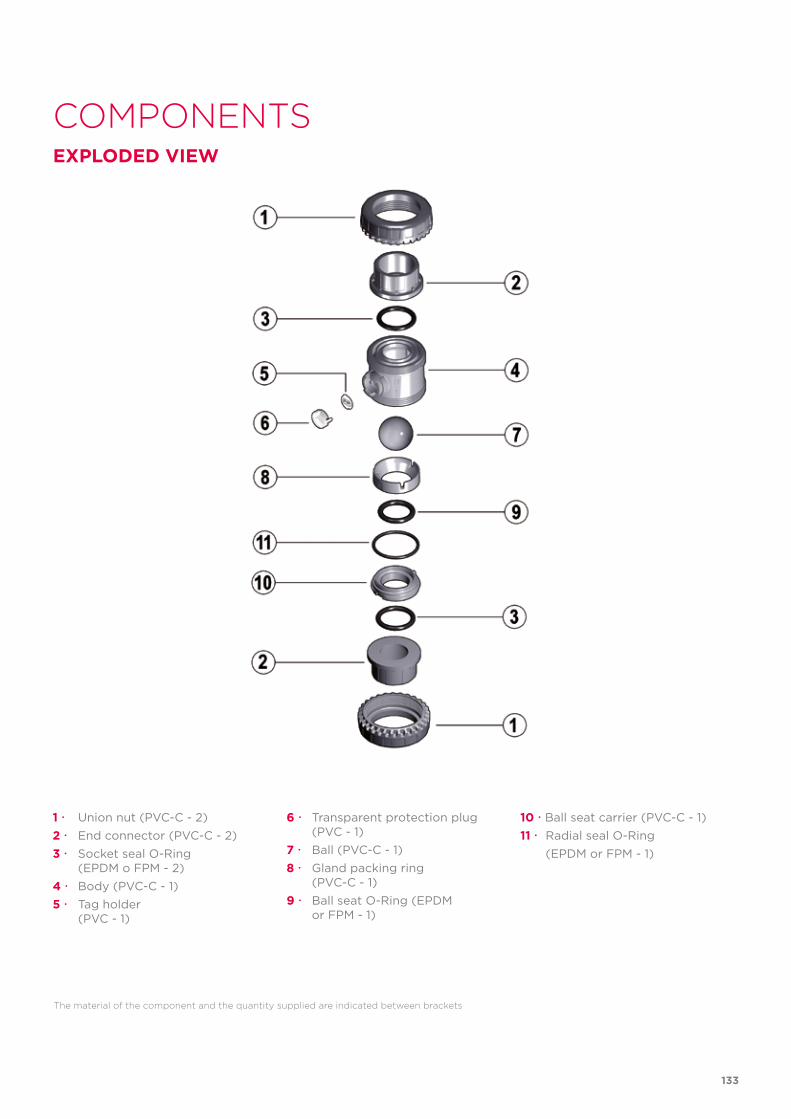
COMPONENTSEXPLODED VIEW
The material of the component and the quantity supplied are indicated between brackets
1 Union nut (PVC-C - 2)2 End connector (PVC-C - 2)3 Socket seal O-Ring (EPDM o FPM - 2)4 Body (PVC-C - 1) 5 Tag holder (PVC - 1)
6 Transparent protection plug (PVC - 1)7 Ball (PVC-C - 1)8 Gland packing ring (PVC-C - 1)9 Ball seat O-Ring (EPDM or FPM - 1)
10 Ball seat carrier (PVC-C - 1)11 Radial seal O-Ring (EPDM or FPM - 1)
133
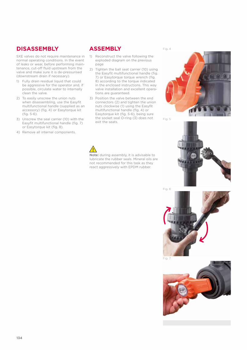
DISASSEMBLY ASSEMBLYSXE valves do not require maintenance in normal operating conditions. In the event of leaks or wear, before performing main-tenance, cut-off fluid upstream from the valve and make sure it is de-pressurised (downstream drain if necessary).1) Fully drain residual liquid that could
be aggressive for the operator and, if possible, circulate water to internally clean the valve.
2) To easily unscrew the union nuts when disassembling, use the Easyfit multifunctional handle (supplied as an accessory) (fig. 4) or Easytorque kit (fig. 5-6).
3) Unscrew the seal carrier (10) with the Easyfit multifunctional handle (fig. 7) or Easytorque kit (fig. 8).
4) Remove all internal components.
1) Reconstruct the valve following the exploded diagram on the previous page
2) Tighten the ball seat carrier (10) using the Easyfit multifunctional handle (fig. 7) or Easytorque torque wrench (fig. 8) according to the torque indicated in the enclosed instructions. This way valve installation and excellent opera-tions are guaranteed.
3) Position the valve between the end connectors (2) and tighten the union nuts clockwise (1) using the Easyfit multifunctional handle (fig. 4) or Easytorque kit (fig. 5-6), being sure the socket seal O-ring (3) does not exit the seats.
Fig. 6
Fig. 7
Fig. 5
Fig. 4
Note: during assembly, it is advisable to lubricate the rubber seals. Mineral oils are not recommended for this task as they react aggressively with EPDM rubber.
134
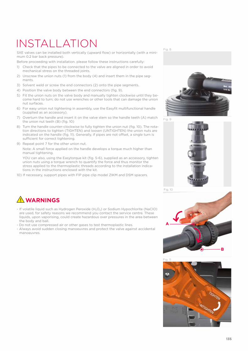
INSTALLATIONSXE valves can be installed both vertically (upward flow) or horizontally (with a mini-mum 0.2 bar back pressure).Before proceeding with installation. please follow these instructions carefully:1) Check that the pipes to be connected to the valve are aligned in order to avoid
mechanical stress on the threaded joints.2) Unscrew the union nuts (1) from the body (4) and insert them in the pipe seg-
ments.3) Solvent weld or screw the end connectors (2) onto the pipe segments.4) Position the valve body between the end connectors (fig. 9).5) Fit the union nuts on the valve body and manually tighten clockwise until they be-
come hard to turn; do not use wrenches or other tools that can damage the union nut surfaces.
6) For easy union nut tightening in assembly, use the Easyfit multifunctional handle (supplied as an accessory).
7) Overturn the handle and insert it on the valve stem so the handle teeth (A) match the union nut teeth (B) (fig. 10)
8) Turn the handle counter-clockwise to fully tighten the union nut (fig. 10). The rota-tion directions to tighten (TIGHTEN) and loosen (UNTIGHTEN) the union nuts are indicated on the handle (fig. 11). Generally, if pipes are not offset, a single turn is sufficient for correct tightening.
9) Repeat point 7 for the other union nut. Note: A small force applied on the handle develops a torque much higher than
manual tightening. YOU can also, using the Easytorque kit (fig. 5-6), supplied as an accessory, tighten
union nuts using a torque wrench to quantify the force and thus monitor the stress applied to the thermoplastic threads according to the installation indica-tions in the instructions enclosed with the kit.
10) If necessary, support pipes with FIP pipe clip model ZIKM and DSM spacers.
Fig. 8
WARNINGS- If volatile liquid such as Hydrogen Peroxide (H2O2) or Sodium Hypochlorite (NaCIO)
are used, for safety reasons we recommend you contact the service centre. These liquids, upon vaporising, could create hazardous over pressures in the area between the body and ball.
- Do not use compressed air or other gases to test thermoplastic lines.- Always avoid sudden closing manoeuvres and protect the valve against accidental
manoeuvres.
Fig. 9
Fig. 11
Fig. 10
A
B
135

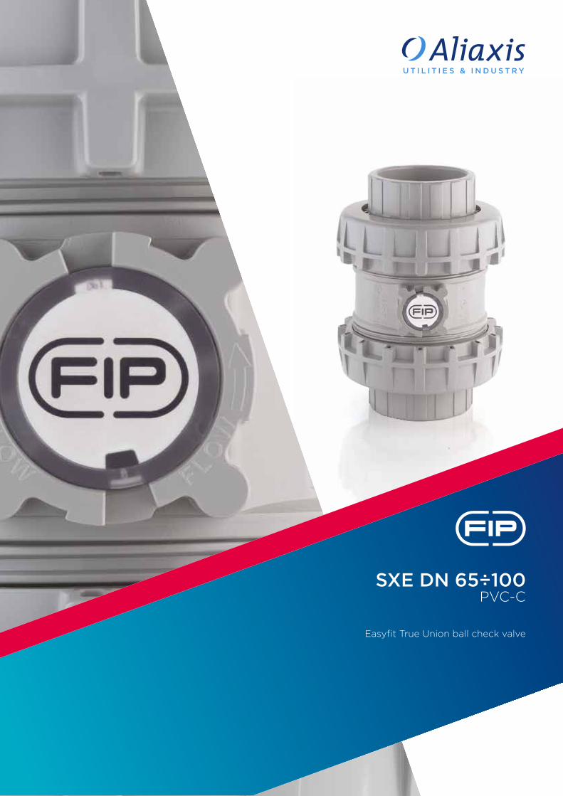
SXE DN 65÷100PVC-C
Easyfit True Union ball check valve
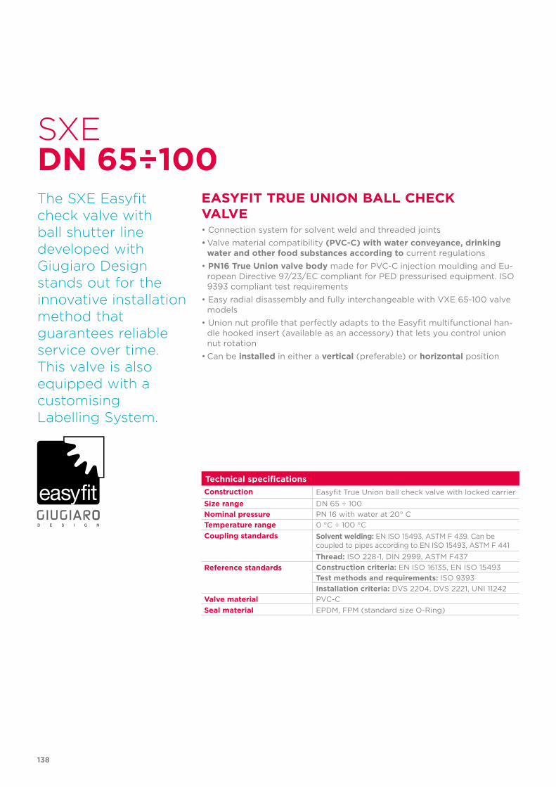
138
Technical specificationsConstruction Easyfit True Union ball check valve with locked carrier Size range DN 65 ÷ 100Nominal pressure PN 16 with water at 20° CTemperature range 0 °C ÷ 100 °CCoupling standards Solvent welding: EN ISO 15493, ASTM F 439. Can be
coupled to pipes according to EN ISO 15493, ASTM F 441Thread: ISO 228-1, DIN 2999, ASTM F437
Reference standards Construction criteria: EN ISO 16135, EN ISO 15493Test methods and requirements: ISO 9393Installation criteria: DVS 2204, DVS 2221, UNI 11242
Valve material PVC-CSeal material EPDM, FPM (standard size O-Ring)
SXE
EASYFIT TRUE UNION BALL CHECK VALVE• Connection system for solvent weld and threaded joints• Valve material compatibility (PVC-C) with water conveyance, drinking
water and other food substances according to current regulations • PN16 True Union valve body made for PVC-C injection moulding and Eu-
ropean Directive 97/23/EC compliant for PED pressurised equipment. ISO 9393 compliant test requirements
• Easy radial disassembly and fully interchangeable with VXE 65-100 valve models
• Union nut profile that perfectly adapts to the Easyfit multifunctional han-dle hooked insert (available as an accessory) that lets you control union nut rotation
• Can be installed in either a vertical (preferable) or horizontal position
DN 65÷100The SXE Easyfitcheck valve with ball shutter line developed withGiugiaro Design stands out for the innovative installation method that guarantees reliable service over time.This valve is alsoequipped with acustomisingLabelling System.
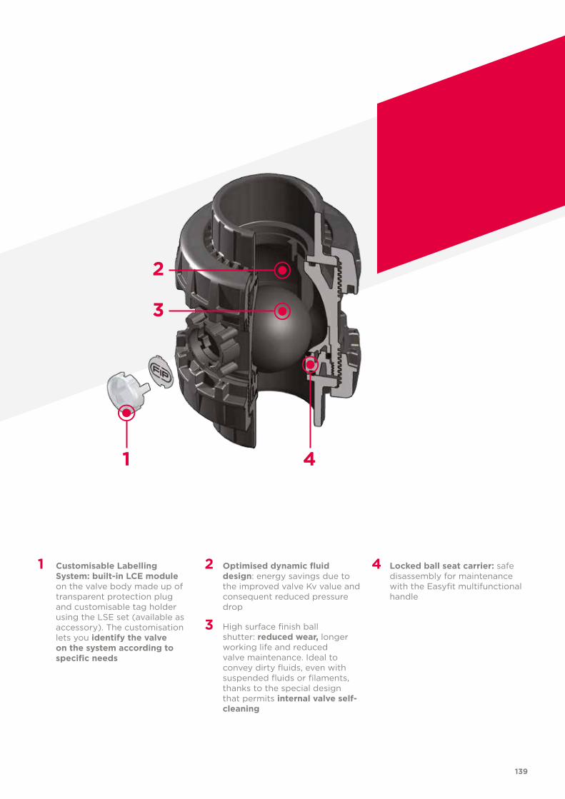
139
1 Customisable Labelling System: built-in LCE module on the valve body made up of transparent protection plug and customisable tag holder using the LSE set (available as accessory). The customisation lets you identify the valve on the system according to specific needs
2 Optimised dynamic fluid design: energy savings due to the improved valve Kv value and consequent reduced pressure drop
3 High surface finish ball shutter: reduced wear, longer working life and reduced valve maintenance. Ideal to convey dirty fluids, even with suspended fluids or filaments, thanks to the special design that permits internal valve self-cleaning
4 Locked ball seat carrier: safe disassembly for maintenance with the Easyfit multifunctional handle
2
3
1 4
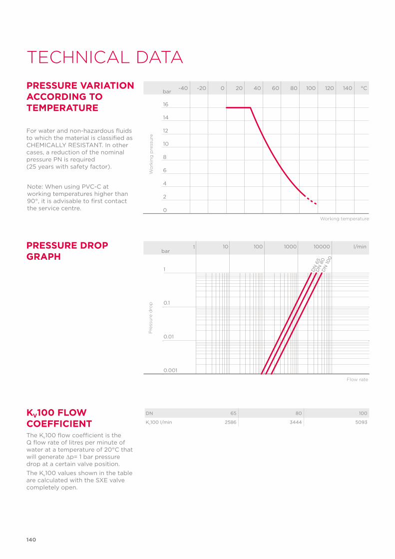
140
TECHNICAL DATA
-40 -20 0 20 40 60 80 100 120 140 °C
16
14
12
10
8
6
4
2
0
Wo
rkin
g p
ress
ure
Working temperature
barPRESSURE VARIATION ACCORDING TO TEMPERATURE
For water and non-hazardous fluids to which the material is classified as CHEMICALLY RESISTANT. In other cases, a reduction of the nominal pressure PN is required (25 years with safety factor).
PRESSURE DROP GRAPH
Pre
ssu
re d
rop
Flow rate
bar1 10 100 1000 10000 l/min
1
0.1
0.01
0.001
DN
65
DN
80
DN
100
KV100 FLOW COEFFICIENTThe Kv100 flow coefficient is the Q flow rate of litres per minute of water at a temperature of 20°C that will generate ∆p= 1 bar pressure drop at a certain valve position.The Kv100 values shown in the table are calculated with the SXE valve completely open.
DN 65 80 100
Kv100 l/min 2586 3444 5093
Note: When using PVC-C at working temperatures higher than 90°, it is advisable to first contact the service centre.
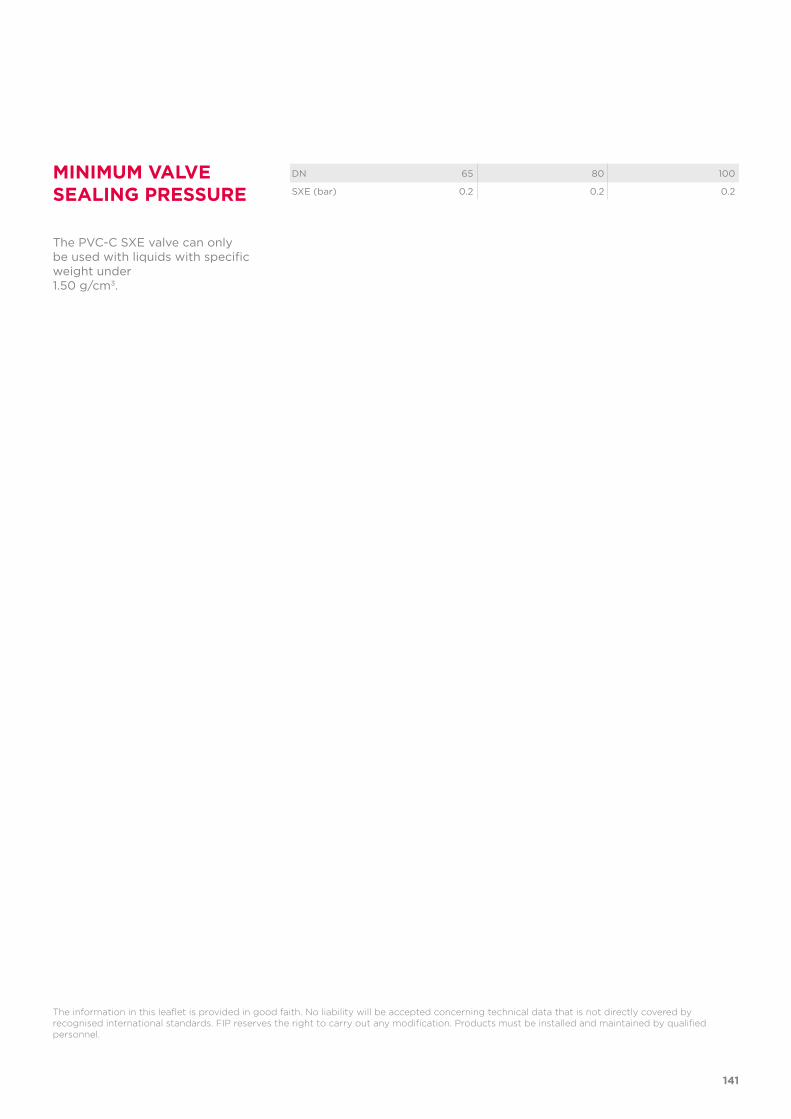
141
The information in this leaflet is provided in good faith. No liability will be accepted concerning technical data that is not directly covered by recognised international standards. FIP reserves the right to carry out any modification. Products must be installed and maintained by qualified personnel.
MINIMUM VALVE SEALING PRESSURE
The PVC-C SXE valve can only be used with liquids with specific weight under 1.50 g/cm3.
DN 65 80 100
SXE (bar) 0.2 0.2 0.2
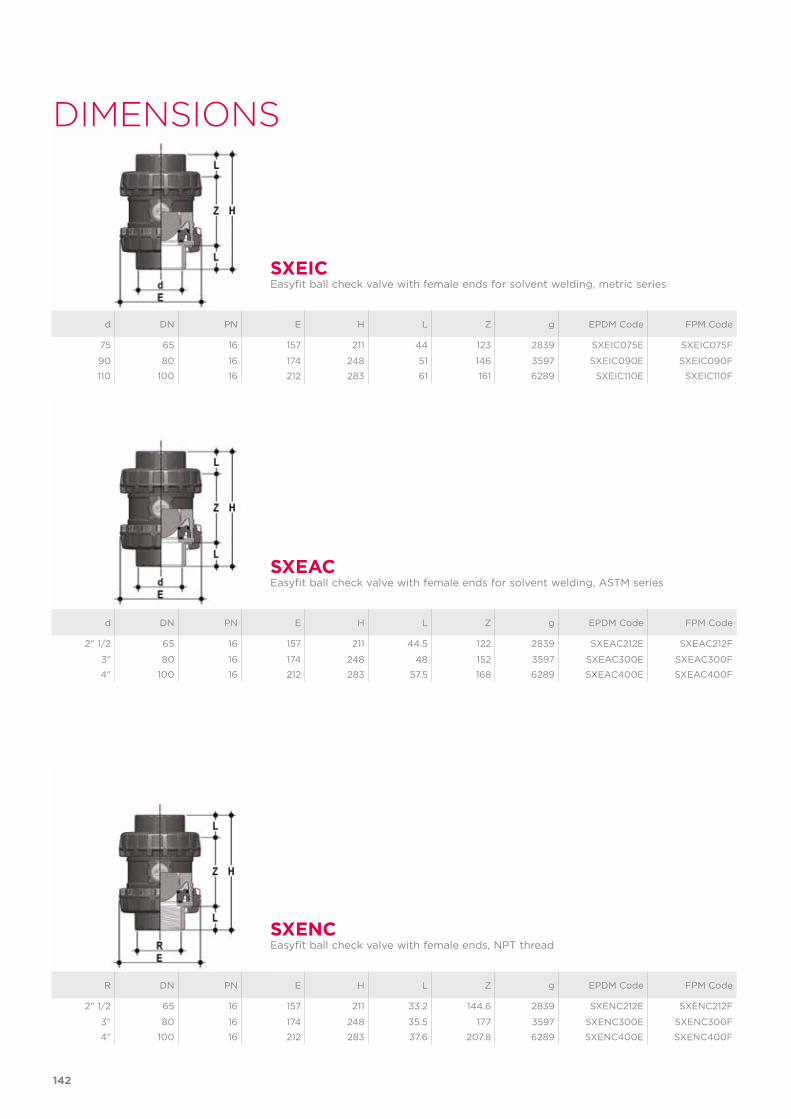
142
d DN PN E H L Z g EPDM Code FPM Code
75 65 16 157 211 44 123 2839 SXEIC075E SXEIC075F
90 80 16 174 248 51 146 3597 SXEIC090E SXEIC090F
110 100 16 212 283 61 161 6289 SXEIC110E SXEIC110F
SXEICEasyfit ball check valve with female ends for solvent welding, metric series
DIMENSIONS
d DN PN E H L Z g EPDM Code FPM Code
2" 1/2 65 16 157 211 44.5 122 2839 SXEAC212E SXEAC212F
3" 80 16 174 248 48 152 3597 SXEAC300E SXEAC300F
4" 100 16 212 283 57.5 168 6289 SXEAC400E SXEAC400F
SXEACEasyfit ball check valve with female ends for solvent welding, ASTM series
R DN PN E H L Z g EPDM Code FPM Code
2" 1/2 65 16 157 211 33.2 144.6 2839 SXENC212E SXENC212F
3" 80 16 174 248 35.5 177 3597 SXENC300E SXENC300F
4" 100 16 212 283 37.6 207.8 6289 SXENC400E SXENC400F
SXENCEasyfit ball check valve with female ends, NPT thread
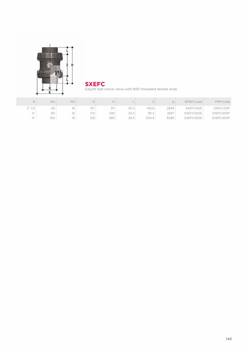
143
R DN PN E H L Z g EPDM Code FPM Code
2" 1/2 65 16 157 211 30.2 150.6 2839 SXEFC212E SXEFC212F
3" 80 16 174 248 33.3 181.4 3597 SXEFC300E SXEFC300F
4" 100 16 212 283 39.3 204.4 6289 SXEFC400E SXEFC400F
SXEFCEasyfit ball check valve with BSP threaded female ends
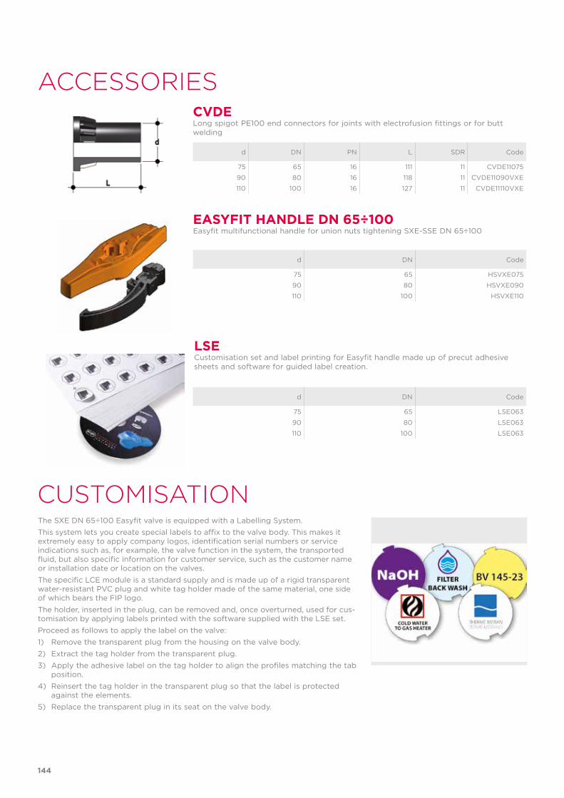
LSECustomisation set and label printing for Easyfit handle made up of precut adhesive sheets and software for guided label creation.
d DN Code
75 65 LSE063
90 80 LSE063
110 100 LSE063
d DN PN L SDR Code
75 65 16 111 11 CVDE11075
90 80 16 118 11 CVDE11090VXE
110 100 16 127 11 CVDE11110VXE
CVDELong spigot PE100 end connectors for joints with electrofusion fittings or for butt welding
d DN Code
75 65 HSVXE075
90 80 HSVXE090
110 100 HSVXE110
EASYFIT HANDLE DN 65÷100Easyfit multifunctional handle for union nuts tightening SXE-SSE DN 65÷100
CUSTOMISATIONThe SXE DN 65÷100 Easyfit valve is equipped with a Labelling System. This system lets you create special labels to affix to the valve body. This makes it extremely easy to apply company logos, identification serial numbers or service indications such as, for example, the valve function in the system, the transported fluid, but also specific information for customer service, such as the customer name or installation date or location on the valves.The specific LCE module is a standard supply and is made up of a rigid transparent water-resistant PVC plug and white tag holder made of the same material, one side of which bears the FIP logo. The holder, inserted in the plug, can be removed and, once overturned, used for cus-tomisation by applying labels printed with the software supplied with the LSE set.Proceed as follows to apply the label on the valve:1) Remove the transparent plug from the housing on the valve body.2) Extract the tag holder from the transparent plug.3) Apply the adhesive label on the tag holder to align the profiles matching the tab
position.4) Reinsert the tag holder in the transparent plug so that the label is protected
against the elements.5) Replace the transparent plug in its seat on the valve body.
144
ACCESSORIES
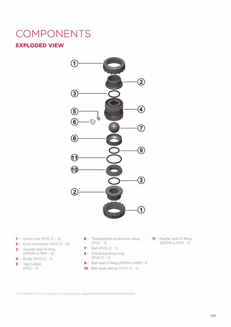
COMPONENTSEXPLODED VIEW
The material of the component and the quantity supplied are indicated between brackets
1 Union nut (PVC-C - 2)2 End connector (PVC-C - 2)3 Socket seal O-ring (EPDM o FPM - 2)4 Body (PVC-C - 1) 5 Tag holder (PVC - 1)
6 Transparent protection plug (PVC - 1)7 Ball (PVC-C - 1)8 Gland packing ring (PVC-C - 1)9 Ball seat O-Ring (EPDM o FPM - 1)10 Ball seat carrier (PVC-C - 1)
11 Radial seal O-Ring (EPDM o FPM - 1)
145
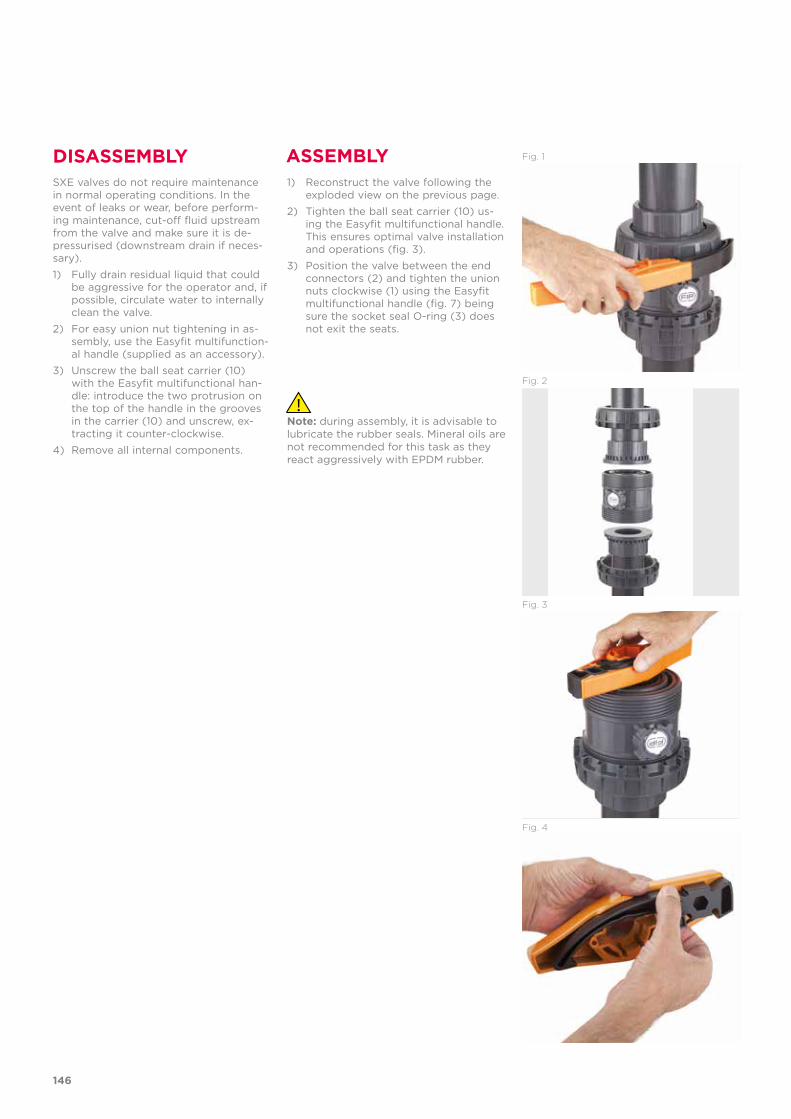
DISASSEMBLY ASSEMBLYSXE valves do not require maintenance in normal operating conditions. In the event of leaks or wear, before perform-ing maintenance, cut-off fluid upstream from the valve and make sure it is de-pressurised (downstream drain if neces-sary).1) Fully drain residual liquid that could
be aggressive for the operator and, if possible, circulate water to internally clean the valve.
2) For easy union nut tightening in as-sembly, use the Easyfit multifunction-al handle (supplied as an accessory).
3) Unscrew the ball seat carrier (10) with the Easyfit multifunctional han-dle: introduce the two protrusion on the top of the handle in the grooves in the carrier (10) and unscrew, ex-tracting it counter-clockwise.
4) Remove all internal components.
1) Reconstruct the valve following the exploded view on the previous page.
2) Tighten the ball seat carrier (10) us-ing the Easyfit multifunctional handle. This ensures optimal valve installation and operations (fig. 3).
3) Position the valve between the end connectors (2) and tighten the union nuts clockwise (1) using the Easyfit multifunctional handle (fig. 7) being sure the socket seal O-ring (3) does not exit the seats.
Note: during assembly, it is advisable to lubricate the rubber seals. Mineral oils are not recommended for this task as they react aggressively with EPDM rubber.
Fig. 3
Fig. 4
Fig. 2
Fig. 1
146
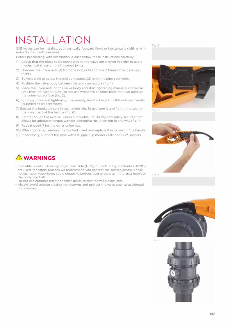
INSTALLATIONFig. 5
Fig. 6
Fig. 7
Fig. 8
SXE valves can be installed both vertically (upward flow) or horizontally (with a mini-mum 0.2 bar back pressure).Before proceeding with installation. please follow these instructions carefully:1) Check that the pipes to be connected to the valve are aligned in order to avoid
mechanical stress on the threaded joints.2) Unscrew the union nuts (1) from the body (4) and insert them in the pipe seg-
ments.3) Solvent weld or screw the end connectors (2) onto the pipe segments.4) Position the valve body between the end connectors (fig. 1). 5) Place the union nuts on the valve body and start tightening manually clockwise
until they are hard to turn. Do not use wrenches or other tools that can damage the union nut surface (fig. 2).
6) For easy union nut tightening in assembly, use the Easyfit multifunctional handle (supplied as an accessory).
7) Extract the hooked insert in the handle (fig. 5) overturn it and fit it in the seat on the lower part of the handle (fig. 6).
8) Fit the tool on the external union nut profile until firmly and safely secured that allows for adequate torque without damaging the union nut in any way (fig. 7).
9) Repeat point 7 for the other union nut.10) When tightened, remove the hooked insert and replace it in its seat in the handle.11) If necessary, support the pipe with FIP pipe clip model ZIKM and DSM spacers.
WARNINGS- If volatile liquid such as Hydrogen Peroxide (H2O2) or Sodium Hypochlorite (NaCIO)
are used, for safety reasons we recommend you contact the service centre. These liquids, upon vaporising, could create hazardous over pressures in the area between the body and ball.
- Do not use compressed air or other gases to test thermoplastic lines.- Always avoid sudden closing manoeuvres and protect the valve against accidental
manoeuvres.
147

FK DN 40÷300 PVC-C
Butterfly valve
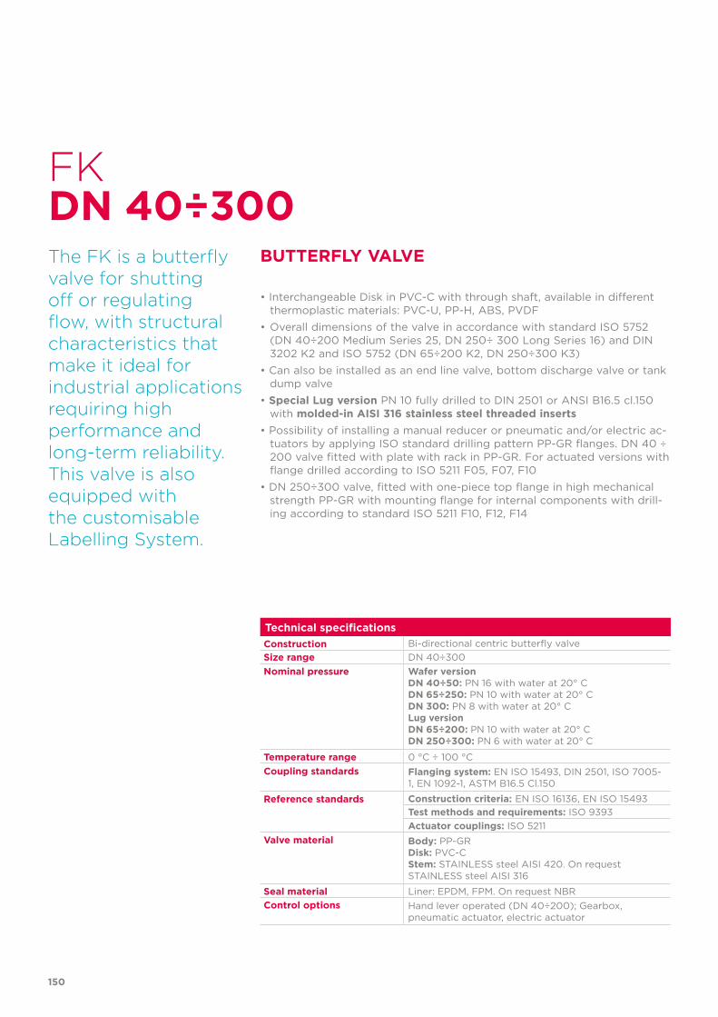
150
Technical specificationsConstruction Bi-directional centric butterfly valveSize range DN 40÷300Nominal pressure Wafer version
DN 40÷50: PN 16 with water at 20° CDN 65÷250: PN 10 with water at 20° CDN 300: PN 8 with water at 20° CLug version DN 65÷200: PN 10 with water at 20° CDN 250÷300: PN 6 with water at 20° C
Temperature range 0 °C ÷ 100 °CCoupling standards Flanging system: EN ISO 15493, DIN 2501, ISO 7005-
1, EN 1092-1, ASTM B16.5 Cl.150
Reference standards Construction criteria: EN ISO 16136, EN ISO 15493Test methods and requirements: ISO 9393Actuator couplings: ISO 5211
Valve material Body: PP-GRDisk: PVC-CStem: STAINLESS steel AISI 420. On request STAINLESS steel AISI 316
Seal material Liner: EPDM, FPM. On request NBRControl options Hand lever operated (DN 40÷200); Gearbox,
pneumatic actuator, electric actuator
FK
The FK is a butterfly valve for shutting off or regulating flow, with structural characteristics that make it ideal for industrial applications requiring high performance and long-term reliability. This valve is also equipped with the customisable Labelling System.
BUTTERFLY VALVE
• Interchangeable Disk in PVC-C with through shaft, available in different thermoplastic materials: PVC-U, PP-H, ABS, PVDF
• Overall dimensions of the valve in accordance with standard ISO 5752 (DN 40÷200 Medium Series 25, DN 250÷ 300 Long Series 16) and DIN 3202 K2 and ISO 5752 (DN 65÷200 K2, DN 250÷300 K3)
• Can also be installed as an end line valve, bottom discharge valve or tank dump valve
• Special Lug version PN 10 fully drilled to DIN 2501 or ANSI B16.5 cl.150 with molded-in AISI 316 stainless steel threaded inserts
• Possibility of installing a manual reducer or pneumatic and/or electric ac-tuators by applying ISO standard drilling pattern PP-GR flanges. DN 40 ÷ 200 valve fitted with plate with rack in PP-GR. For actuated versions with flange drilled according to ISO 5211 F05, F07, F10
• DN 250÷300 valve, fitted with one-piece top flange in high mechanical strength PP-GR with mounting flange for internal components with drill-ing according to standard ISO 5211 F10, F12, F14
DN 40÷300
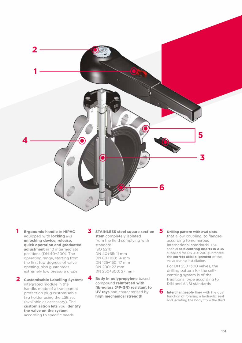
151
1 Ergonomic handle in HIPVC equipped with locking and unlocking device, release, quick operation and graduated adjustment in 10 intermediate positions (DN 40÷200). The operating range, starting from the first few degrees of valve opening, also guarantees extremely low pressure drops
2 Customisable Labelling System: integrated module in the handle, made of a transparent protection plug customisable tag holder using the LSE set (available as accessory). The customisation lets you identify the valve on the system according to specific needs
3 STAINLESS steel square section stem completely isolated from the fluid complying with standard
ISO 5211: DN 40÷65: 11 mm DN 80÷100: 14 mm DN 125÷150: 17 mm DN 200: 22 mm DN 250÷300: 27 mm
4 Body in polypropylene based compound reinforced with fibreglass (PP-GR) resistant to UV rays and characterised by high mechanical strength
5 Drilling pattern with oval slots that allow coupling to flanges according to numerous international standards. The special self-centring inserts in ABS supplied for DN 40÷200 guarantee the correct axial alignment of the valve during installation.
For DN 250÷300 valves, the drilling pattern for the self-centring system is of the traditional type according to DIN and ANSI standards
6 Interchangeable liner with the dual function of forming a hydraulic seal and isolating the body from the fluid
2
3
1
4 5
6
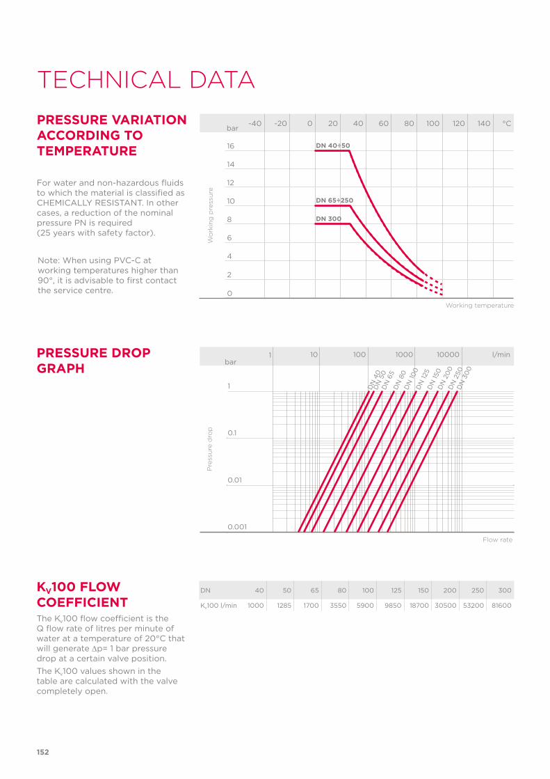
152
TECHNICAL DATA
DN 40 50 65 80 100 125 150 200 250 300
Kv100 l/min 1000 1285 1700 3550 5900 9850 18700 30500 53200 81600
KV100 FLOW COEFFICIENTThe Kv100 flow coefficient is the Q flow rate of litres per minute of water at a temperature of 20°C that will generate ∆p= 1 bar pressure drop at a certain valve position.The Kv100 values shown in the table are calculated with the valve completely open.
PRESSURE DROP GRAPH
Pre
ssu
re d
rop
Flow rate
bar1 10 100 1000 10000 l/min
1
0.1
0.01
0.001
DN
40
DN
50
DN
65
DN
80
DN
100
DN
125
DN
150
DN
20
0D
N 2
50D
N 3
00
-40 -20 0 20 40 60 80 100 120 140 °C
16
14
12
10
8
6
4
2
0
Wo
rkin
g p
ress
ure
Working temperature
barPRESSURE VARIATION ACCORDING TO TEMPERATURE
For water and non-hazardous fluids to which the material is classified as CHEMICALLY RESISTANT. In other cases, a reduction of the nominal pressure PN is required (25 years with safety factor).
DN 40÷50
DN 65÷250
DN 300
Note: When using PVC-C at working temperatures higher than 90°, it is advisable to first contact the service centre.
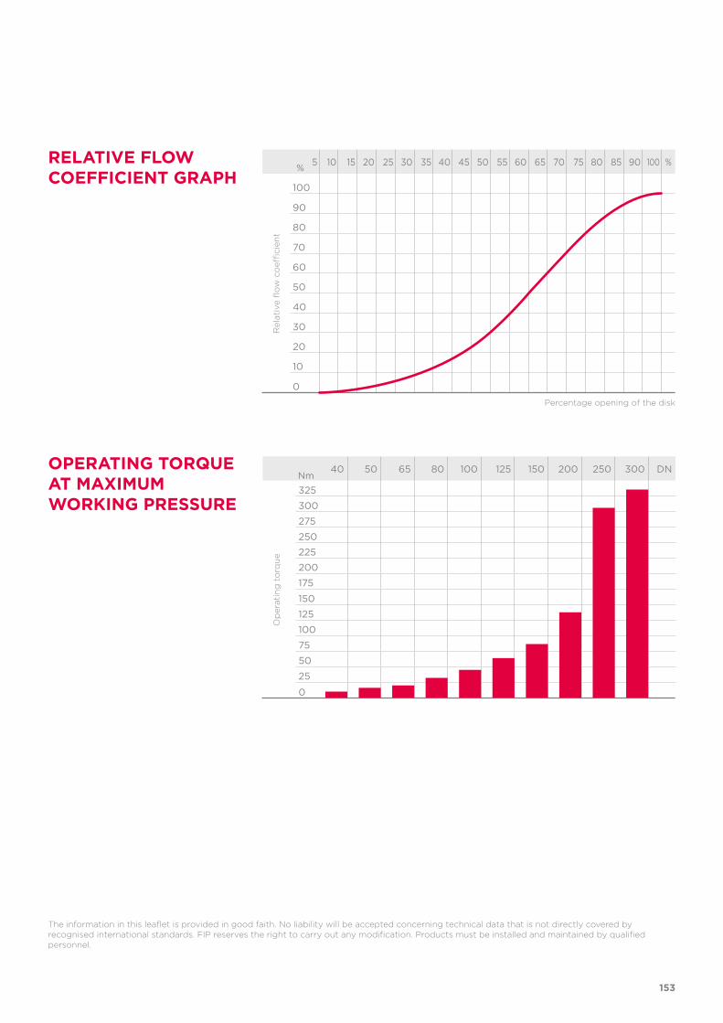
153
The information in this leaflet is provided in good faith. No liability will be accepted concerning technical data that is not directly covered by recognised international standards. FIP reserves the right to carry out any modification. Products must be installed and maintained by qualified personnel.
OPERATING TORQUE AT MAXIMUM WORKING PRESSURE
40 50 65 80 100 125 150 200 250 300 DN
325
300
275
250
225
200
175
150
125
100
75
50
25
0
Op
erat
ing
to
rqu
e
Nm
RELATIVE FLOW COEFFICIENT GRAPH
5 10 15 20 25 30 35 40 45 50 55 60 65 70 75 80 85 90 100 %
100
90
80
70
60
50
40
30
20
10
0
Rel
ativ
e fl
ow
co
effici
ent
Percentage opening of the disk
%
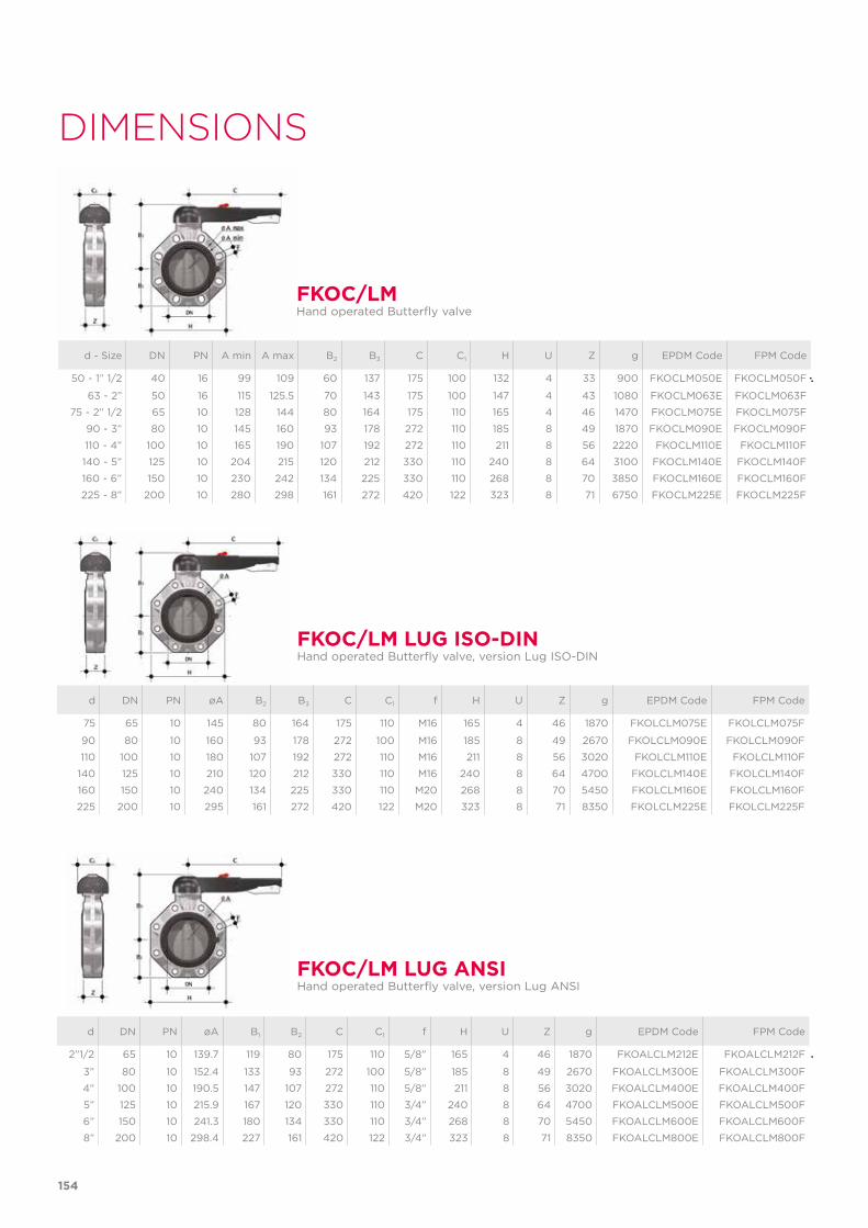
154
DIMENSIONS
d - Size DN PN A min A max B2 B3 C C1 H U Z g EPDM Code FPM Code
50 - 1” 1/2 40 16 99 109 60 137 175 100 132 4 33 900 FKOCLM050E FKOCLM050F
63 - 2” 50 16 115 125.5 70 143 175 100 147 4 43 1080 FKOCLM063E FKOCLM063F
75 - 2” 1/2 65 10 128 144 80 164 175 110 165 4 46 1470 FKOCLM075E FKOCLM075F
90 - 3” 80 10 145 160 93 178 272 110 185 8 49 1870 FKOCLM090E FKOCLM090F
110 - 4” 100 10 165 190 107 192 272 110 211 8 56 2220 FKOCLM110E FKOCLM110F
140 - 5” 125 10 204 215 120 212 330 110 240 8 64 3100 FKOCLM140E FKOCLM140F
160 - 6” 150 10 230 242 134 225 330 110 268 8 70 3850 FKOCLM160E FKOCLM160F
225 - 8” 200 10 280 298 161 272 420 122 323 8 71 6750 FKOCLM225E FKOCLM225F
FKOC/LMHand operated Butterfly valve
d DN PN øA B2 B3 C C1 f H U Z g EPDM Code FPM Code
75 65 10 145 80 164 175 110 M16 165 4 46 1870 FKOLCLM075E FKOLCLM075F
90 80 10 160 93 178 272 100 M16 185 8 49 2670 FKOLCLM090E FKOLCLM090F
110 100 10 180 107 192 272 110 M16 211 8 56 3020 FKOLCLM110E FKOLCLM110F
140 125 10 210 120 212 330 110 M16 240 8 64 4700 FKOLCLM140E FKOLCLM140F
160 150 10 240 134 225 330 110 M20 268 8 70 5450 FKOLCLM160E FKOLCLM160F
225 200 10 295 161 272 420 122 M20 323 8 71 8350 FKOLCLM225E FKOLCLM225F
FKOC/LM LUG ISO-DINHand operated Butterfly valve, version Lug ISO-DIN
d DN PN øA B1 B2 C C1 f H U Z g EPDM Code FPM Code
2”1/2 65 10 139.7 119 80 175 110 5/8” 165 4 46 1870 FKOALCLM212E FKOALCLM212F
3” 80 10 152.4 133 93 272 100 5/8” 185 8 49 2670 FKOALCLM300E FKOALCLM300F
4” 100 10 190.5 147 107 272 110 5/8” 211 8 56 3020 FKOALCLM400E FKOALCLM400F
5” 125 10 215.9 167 120 330 110 3/4” 240 8 64 4700 FKOALCLM500E FKOALCLM500F
6” 150 10 241.3 180 134 330 110 3/4” 268 8 70 5450 FKOALCLM600E FKOALCLM600F
8” 200 10 298.4 227 161 420 122 3/4” 323 8 71 8350 FKOALCLM800E FKOALCLM800F
FKOC/LM LUG ANSIHand operated Butterfly valve, version Lug ANSI
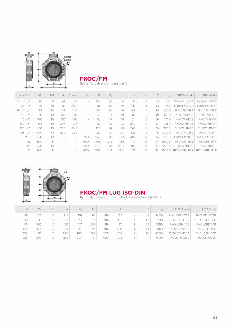
155
d - Size DN PN A min A max øA B1 B2 f H U Z g EPDM Code FPM Code
50 - 1” 1/2 40 16 99 109 - 106 60 19 132 4 33 574 FKOCFM050E FKOCFM050F
63 - 2” 50 16 115 125.5 - 112 70 19 147 4 43 754 FKOCFM063E FKOCFM063F
75 - 2” 1/2 65 10 128 144 - 119 80 19 165 4 46 1000 FKOCFM075E FKOCFM075F
90 - 3” 80 10 145 160 - 133 93 19 185 8 49 1400 FKOCFM090E FKOCFM090F
110 - 4” 100 10 165 190 - 147 107 19 211 8 56 1750 FKOCFM110E FKOCFM110F
140 - 5” 125 10 204 215 - 167 120 23 240 8 64 2550 FKOCFM140E FKOCFM140F
160 - 6” 150 10 230 242 - 180 134 23 268 8 70 3300 FKOCFM160E FKOCFM160F
225 - 8” 200 10 280 298 - 227 161 23 323 8 71 6000 FKOCFM225E FKOCFM225F
280 250 10 - - 350 248 210 22 405 12 114 12000 FKOCFM280E FKOCFM280F
315 300 8 - - 400 305 245 29 475 12 114 19000 FKOCFM315E FKOCFM315F
10” 250 10 - - 350 248 210 25.4 405 12 114 12000 FKOACFM810E FKOACFM810F
12” 300 8 - - 400 305 245 25.4 475 12 114 19000 FKOACFM812E FKOACFM812F
FKOC/FMButterfly valve with bare shaft
d DN PN øA B1 B2 f H U Z g EPDM Code FPM Code
75 65 10 145 119 80 M16 165 4 46 1400 FKOLCFM075E FKOLCFM075F
90 80 10 160 133 93 M16 185 8 49 2200 FKOLCFM090E FKOLCFM090F
110 100 10 180 147 107 M16 211 8 56 2550 FKOLCFM110E FKOLCFM110F
140 125 10 210 167 120 M16 240 8 64 4150 FKOLCFM140E FKOLCFM140F
160 150 10 240 180 134 M20 268 8 70 4900 FKOLCFM160E FKOLCFM160F
225 200 10 295 227 161 M20 323 8 71 7600 FKOLCFM225E FKOLCFM225F
FKOC/FM LUG ISO-DINButterfly valve with bare shaft, version Lug ISO-DIN
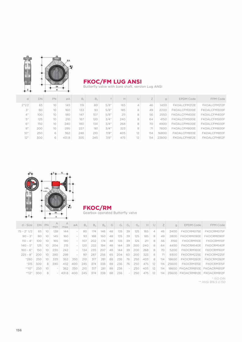
156
d DN PN øA B1 B2 f H U Z g EPDM Code FPM Code
2”1/2 65 10 145 119 80 5/8” 165 4 46 1400 FKOALCFM212E FKOALCFM212F
3” 80 10 160 133 93 5/8” 185 8 49 2200 FKOALCFM300E FKOALCFM300F
4” 100 10 180 147 107 5/8” 211 8 56 2550 FKOALCFM400E FKOALCFM400F
5” 125 10 210 167 120 3/4” 240 8 64 4150 FKOALCFM500E FKOALCFM500F
6” 150 10 240 180 134 3/4” 268 8 70 4900 FKOALCFM600E FKOALCFM600F
8” 200 10 295 227 161 3/4” 323 8 71 7600 FKOALCFM800E FKOALCFM800F
10” 250 6 362 248 210 7/8” 405 12 114 16800 FKOALCFM810E FKOALCFM810F
12” 300 6 431.8 305 245 7/8” 475 12 114 23800 FKOALCFM812E FKOALCFM812F
FKOC/FM LUG ANSIButterfly valve with bare shaft, version Lug ANSI
FKOC/RMGearbox operated Butterfly valve
d - Size DN PN A min
A max øA B2 B5 B6 G G1 G2 G3 H U Z g EPDM Code FPM Code
75 - 2” 1/2 65 10 128 144 - 80 174 146 48 135 39 125 165 4 46 2400 FKOCRM075E FKOCRM075F
90 - 3” 80 10 145 160 - 93 188 160 48 135 39 125 185 8 49 2800 FKOCRM090E FKOCRM090F
110 - 4” 100 10 165 190 - 107 202 174 48 135 39 125 211 8 56 3150 FKOCRM110E FKOCRM110F
140 - 5” 125 10 204 215 - 120 222 194 48 144 39 200 240 8 64 4450 FKOCRM140E FKOCRM140F
160 - 6” 150 10 230 242 - 134 235 207 48 144 39 200 268 8 70 5200 FKOCRM160E FKOCRM160F
225 - 8” 200 10 280 298 - 161 287 256 65 204 60 200 323 8 71 9300 FKOCRM225E FKOCRM225F
*280 250 10 335 362 350 210 317 281 88 236 76 250 405 8 114 18600 FKOCRM280E FKOCRM280F
*315 300 8 390 432 400 245 374 338 88 236 76 250 475 12 114 25600 FKOCRM315E FKOCRM315F
**10” 250 10 - 362 350 210 317 281 88 236 - 250 405 12 114 18600 FKOACRM810E FKOACRM810F
**12” 300 8 - 431.8 400 245 374 338 88 236 - 250 475 12 114 25600 FKOACRM812E FKOACRM812F
* ISO-DIN** ANSI B16.5 cl.150
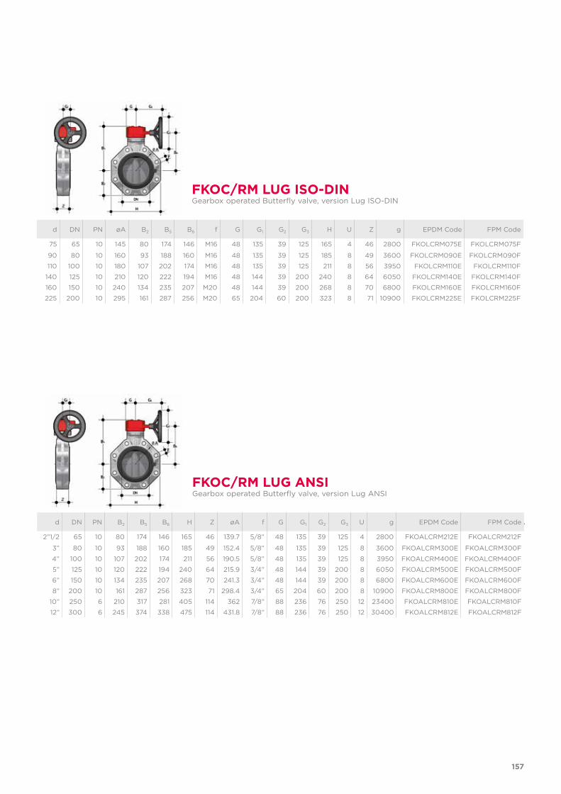
157
FKOC/RM LUG ISO-DINGearbox operated Butterfly valve, version Lug ISO-DIN
d DN PN øA B2 B5 B6 f G G1 G2 G3 H U Z g EPDM Code FPM Code
75 65 10 145 80 174 146 M16 48 135 39 125 165 4 46 2800 FKOLCRM075E FKOLCRM075F
90 80 10 160 93 188 160 M16 48 135 39 125 185 8 49 3600 FKOLCRM090E FKOLCRM090F
110 100 10 180 107 202 174 M16 48 135 39 125 211 8 56 3950 FKOLCRM110E FKOLCRM110F
140 125 10 210 120 222 194 M16 48 144 39 200 240 8 64 6050 FKOLCRM140E FKOLCRM140F
160 150 10 240 134 235 207 M20 48 144 39 200 268 8 70 6800 FKOLCRM160E FKOLCRM160F
225 200 10 295 161 287 256 M20 65 204 60 200 323 8 71 10900 FKOLCRM225E FKOLCRM225F
FKOC/RM LUG ANSIGearbox operated Butterfly valve, version Lug ANSI
d DN PN B2 B5 B6 H Z øA f G G1 G2 G3 U g EPDM Code FPM Code
2”1/2 65 10 80 174 146 165 46 139.7 5/8” 48 135 39 125 4 2800 FKOALCRM212E FKOALCRM212F
3” 80 10 93 188 160 185 49 152.4 5/8” 48 135 39 125 8 3600 FKOALCRM300E FKOALCRM300F
4” 100 10 107 202 174 211 56 190.5 5/8” 48 135 39 125 8 3950 FKOALCRM400E FKOALCRM400F
5” 125 10 120 222 194 240 64 215.9 3/4” 48 144 39 200 8 6050 FKOALCRM500E FKOALCRM500F
6” 150 10 134 235 207 268 70 241.3 3/4” 48 144 39 200 8 6800 FKOALCRM600E FKOALCRM600F
8” 200 10 161 287 256 323 71 298.4 3/4” 65 204 60 200 8 10900 FKOALCRM800E FKOALCRM800F
10” 250 6 210 317 281 405 114 362 7/8” 88 236 76 250 12 23400 FKOALCRM810E FKOALCRM810F
12” 300 6 245 374 338 475 114 431.8 7/8” 88 236 76 250 12 30400 FKOALCRM812E FKOALCRM812F
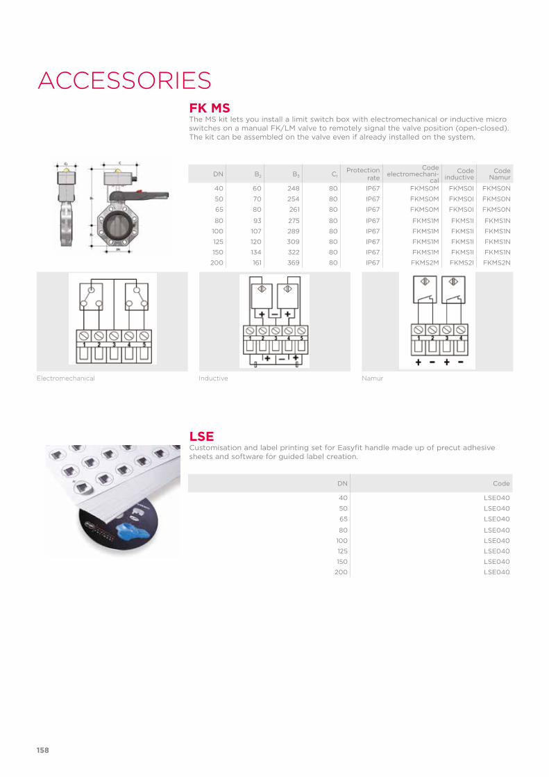
158
FK MS
LSE
ACCESSORIESThe MS kit lets you install a limit switch box with electromechanical or inductive micro switches on a manual FK/LM valve to remotely signal the valve position (open-closed). The kit can be assembled on the valve even if already installed on the system.
Customisation and label printing set for Easyfit handle made up of precut adhesive sheets and software for guided label creation.
DN B2 B3 C1Protection
rate
Codeelectromechani-
calCode
inductiveCode
Namur
40 60 248 80 IP67 FKMS0M FKMS0I FKMS0N
50 70 254 80 IP67 FKMS0M FKMS0I FKMS0N
65 80 261 80 IP67 FKMS0M FKMS0I FKMS0N
80 93 275 80 IP67 FKMS1M FKMS1I FKMS1N
100 107 289 80 IP67 FKMS1M FKMS1I FKMS1N
125 120 309 80 IP67 FKMS1M FKMS1I FKMS1N
150 134 322 80 IP67 FKMS1M FKMS1I FKMS1N
200 161 369 80 IP67 FKMS2M FKMS2I FKMS2N
DN Code
40 LSE040
50 LSE040
65 LSE040
80 LSE040
100 LSE040
125 LSE040
150 LSE040
200 LSE040
Electromechanical Inductive Namur
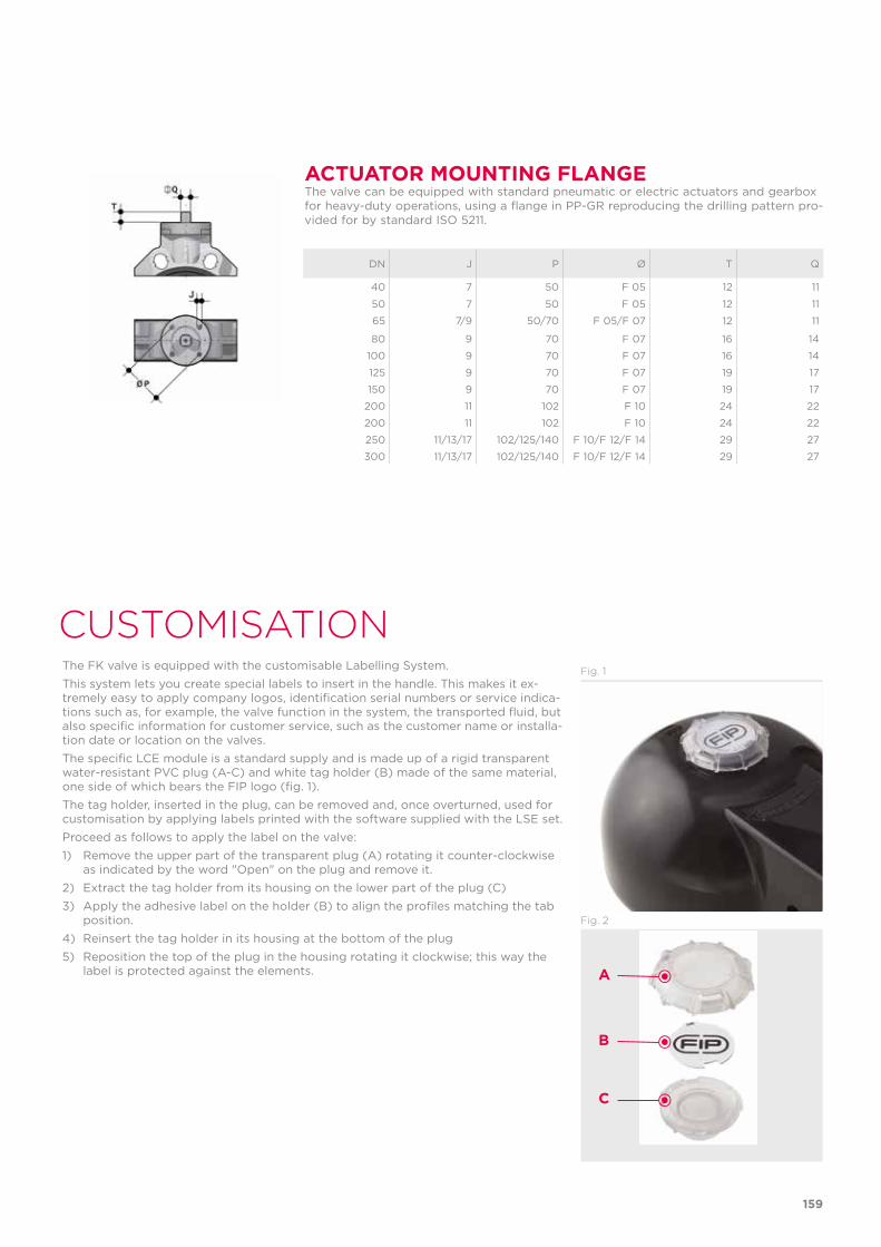
159
ACTUATOR MOUNTING FLANGE The valve can be equipped with standard pneumatic or electric actuators and gearbox for heavy-duty operations, using a flange in PP-GR reproducing the drilling pattern pro-vided for by standard ISO 5211.
DN J P Ø T Q
40 7 50 F 05 12 11
50 7 50 F 05 12 11
65 7/9 50/70 F 05/F 07 12 11
80 9 70 F 07 16 14
100 9 70 F 07 16 14
125 9 70 F 07 19 17
150 9 70 F 07 19 17
200 11 102 F 10 24 22
200 11 102 F 10 24 22
250 11/13/17 102/125/140 F 10/F 12/F 14 29 27
300 11/13/17 102/125/140 F 10/F 12/F 14 29 27
CUSTOMISATIONThe FK valve is equipped with the customisable Labelling System.This system lets you create special labels to insert in the handle. This makes it ex-tremely easy to apply company logos, identification serial numbers or service indica-tions such as, for example, the valve function in the system, the transported fluid, but also specific information for customer service, such as the customer name or installa-tion date or location on the valves.The specific LCE module is a standard supply and is made up of a rigid transparent water-resistant PVC plug (A-C) and white tag holder (B) made of the same material, one side of which bears the FIP logo (fig. 1).The tag holder, inserted in the plug, can be removed and, once overturned, used for customisation by applying labels printed with the software supplied with the LSE set. Proceed as follows to apply the label on the valve:1) Remove the upper part of the transparent plug (A) rotating it counter-clockwise
as indicated by the word "Open" on the plug and remove it.2) Extract the tag holder from its housing on the lower part of the plug (C)3) Apply the adhesive label on the holder (B) to align the profiles matching the tab
position.4) Reinsert the tag holder in its housing at the bottom of the plug 5) Reposition the top of the plug in the housing rotating it clockwise; this way the
label is protected against the elements.
Fig. 1
Fig. 2
A
B
C
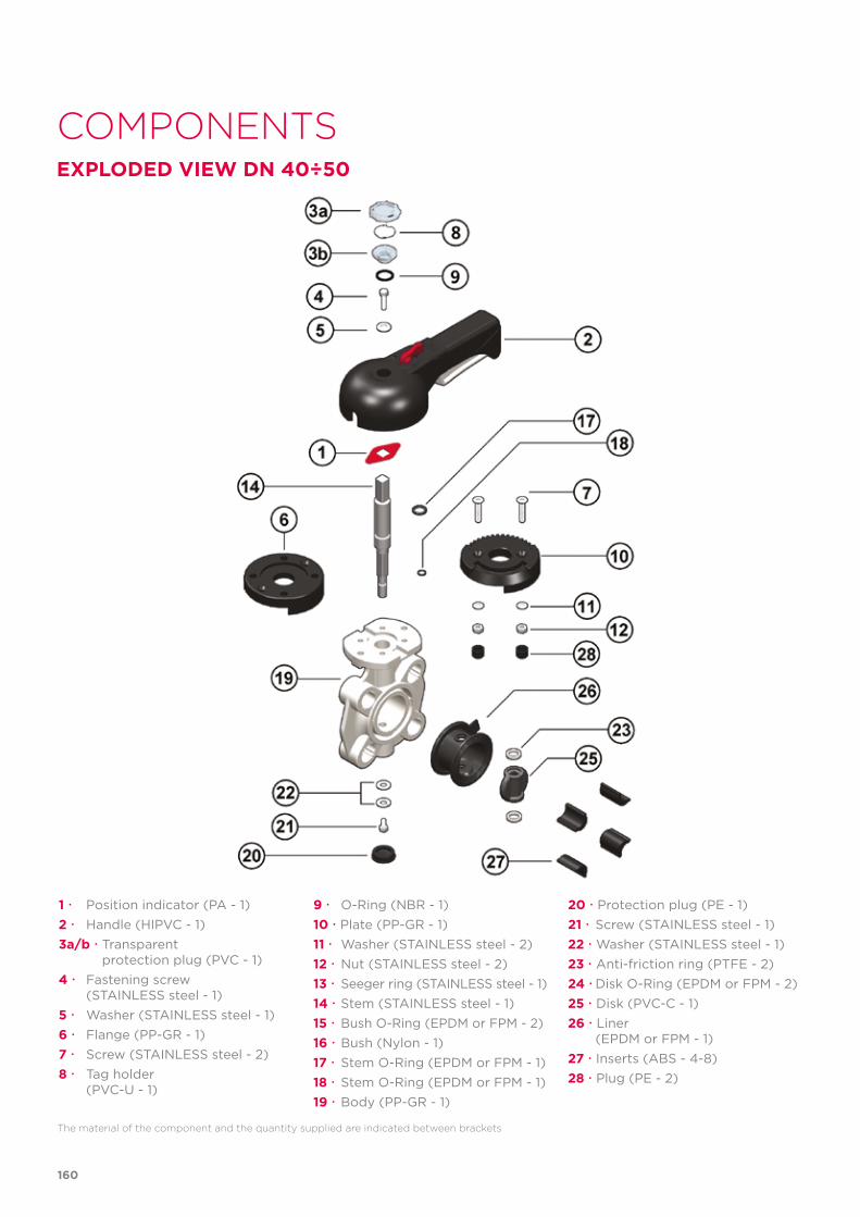
COMPONENTSEXPLODED VIEW DN 40÷50
The material of the component and the quantity supplied are indicated between brackets
1 Position indicator (PA - 1)2 Handle (HIPVC - 1)3a/b Transparent protection plug (PVC - 1)4 Fastening screw (STAINLESS steel - 1)5 Washer (STAINLESS steel - 1)6 Flange (PP-GR - 1)7 Screw (STAINLESS steel - 2)8 Tag holder (PVC-U - 1)
9 O-Ring (NBR - 1)10 Plate (PP-GR - 1)11 Washer (STAINLESS steel - 2)12 Nut (STAINLESS steel - 2)13 Seeger ring (STAINLESS steel - 1)14 Stem (STAINLESS steel - 1)15 Bush O-Ring (EPDM or FPM - 2)16 Bush (Nylon - 1)17 Stem O-Ring (EPDM or FPM - 1)18 Stem O-Ring (EPDM or FPM - 1)19 Body (PP-GR - 1)
20 Protection plug (PE - 1)21 Screw (STAINLESS steel - 1)22 Washer (STAINLESS steel - 1)23 Anti-friction ring (PTFE - 2)24 Disk O-Ring (EPDM or FPM - 2)25 Disk (PVC-C - 1)26 Liner (EPDM or FPM - 1)27 Inserts (ABS - 4-8)28 Plug (PE - 2)
160
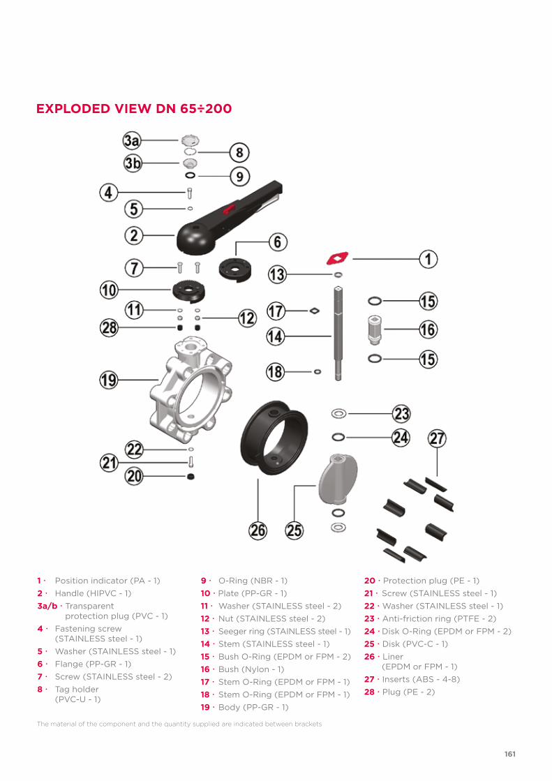
EXPLODED VIEW DN 65÷200
1 Position indicator (PA - 1)2 Handle (HIPVC - 1)3a/b Transparent protection plug (PVC - 1)4 Fastening screw (STAINLESS steel - 1)5 Washer (STAINLESS steel - 1)6 Flange (PP-GR - 1)7 Screw (STAINLESS steel - 2)8 Tag holder (PVC-U - 1)
9 O-Ring (NBR - 1)10 Plate (PP-GR - 1)11 Washer (STAINLESS steel - 2)12 Nut (STAINLESS steel - 2)13 Seeger ring (STAINLESS steel - 1)14 Stem (STAINLESS steel - 1)15 Bush O-Ring (EPDM or FPM - 2)16 Bush (Nylon - 1)17 Stem O-Ring (EPDM or FPM - 1)18 Stem O-Ring (EPDM or FPM - 1)19 Body (PP-GR - 1)
20 Protection plug (PE - 1)21 Screw (STAINLESS steel - 1)22 Washer (STAINLESS steel - 1)23 Anti-friction ring (PTFE - 2)24 Disk O-Ring (EPDM or FPM - 2)25 Disk (PVC-C - 1)26 Liner (EPDM or FPM - 1)27 Inserts (ABS - 4-8)28 Plug (PE - 2)
The material of the component and the quantity supplied are indicated between brackets
161
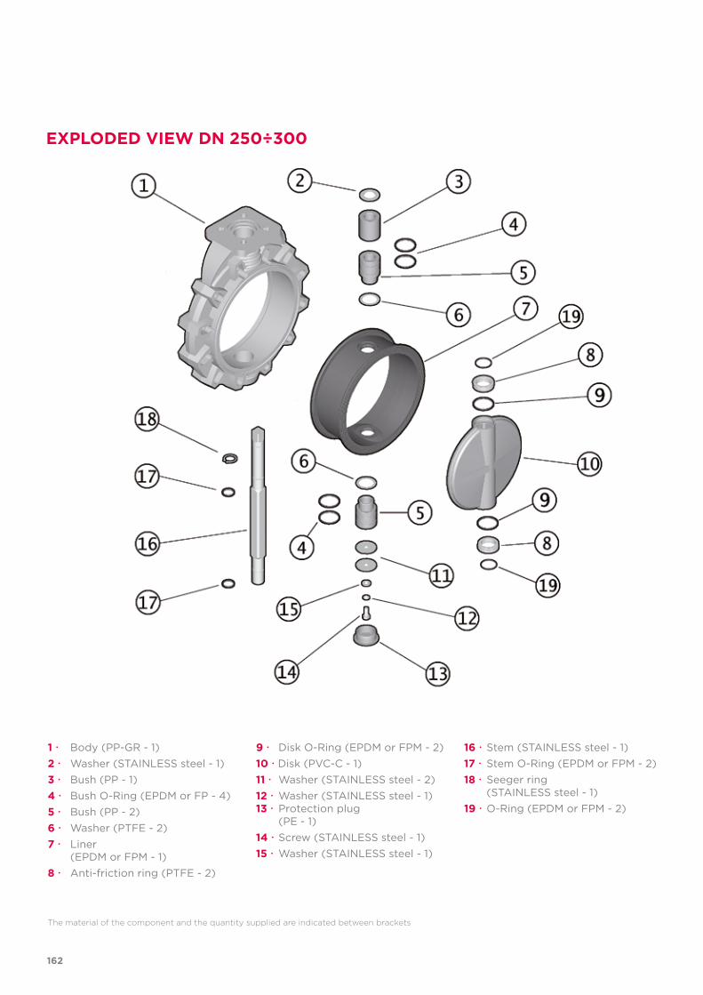
EXPLODED VIEW DN 250÷300
1 Body (PP-GR - 1)2 Washer (STAINLESS steel - 1)3 Bush (PP - 1)4 Bush O-Ring (EPDM or FP - 4)5 Bush (PP - 2)6 Washer (PTFE - 2)7 Liner (EPDM or FPM - 1)8 Anti-friction ring (PTFE - 2)
9 Disk O-Ring (EPDM or FPM - 2)10 Disk (PVC-C - 1)11 Washer (STAINLESS steel - 2)12 Washer (STAINLESS steel - 1)13 Protection plug (PE - 1)14 Screw (STAINLESS steel - 1)15 Washer (STAINLESS steel - 1)
16 Stem (STAINLESS steel - 1)17 Stem O-Ring (EPDM or FPM - 2)18 Seeger ring (STAINLESS steel - 1)19 O-Ring (EPDM or FPM - 2)
The material of the component and the quantity supplied are indicated between brackets
162
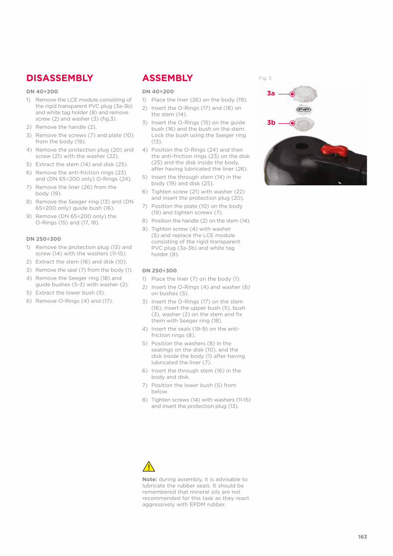
DISASSEMBLY ASSEMBLY Fig. 3
DN 40÷200 1) Place the liner (26) on the body (19).
2) Insert the O-Rings (17) and (18) on the stem (14).
3) Insert the O-Rings (15) on the guide bush (16) and the bush on the stem. Lock the bush using the Seeger ring (13).
4) Position the O-Rings (24) and then the anti-friction rings (23) on the disk (25) and the disk inside the body, after having lubricated the liner (26).
5) Insert the through stem (14) in the body (19) and disk (25).
6) Tighten screw (21) with washer (22) and insert the protection plug (20).
7) Position the plate (10) on the body (19) and tighten screws (7).
8) Position the handle (2) on the stem (14).
9) Tighten screw (4) with washer (5) and replace the LCE module consisting of the rigid transparent PVC plug (3a-3b) and white tag holder (8).
DN 250÷300 1) Place the liner (7) on the body (1).
2) Insert the O-Rings (4) and washer (6) on bushes (5).
3) Insert the O-Rings (17) on the stem (16); insert the upper bush (5), bush (3), washer (2) on the stem and fix them with Seeger ring (18).
4) Insert the seals (19-9) on the anti-friction rings (8).
5) Position the washers (8) in the seatings on the disk (10), and the disk inside the body (1) after having lubricated the liner (7).
6) Insert the through stem (16) in the body and disk.
7) Position the lower bush (5) from below.
8) Tighten screws (14) with washers (11-15) and insert the protection plug (13).
Note: during assembly, it is advisable to lubricate the rubber seals. It should be remembered that mineral oils are not recommended for this task as they react aggressively with EPDM rubber.
DN 40÷200 1) Remove the LCE module consisting of
the rigid transparent PVC plug (3a-3b) and white tag holder (8) and remove screw (2) and washer (3) (fig.3).
2) Remove the handle (2).
3) Remove the screws (7) and plate (10) from the body (19).
4) Remove the protection plug (20) and screw (21) with the washer (22).
5) Extract the stem (14) and disk (25).
6) Remove the anti-friction rings (23) and (DN 65÷200 only) O-Rings (24).
7) Remove the liner (26) from the body (19).
8) Remove the Seeger ring (13) and (DN 65÷200 only) guide bush (16).
9) Remove (DN 65÷200 only) the O-Rings (15) and (17, 18).
DN 250÷300 1) Remove the protection plug (13) and
screw (14) with the washers (11-15).
2) Extract the stem (16) and disk (10).
3) Remove the seal (7) from the body (1).
4) Remove the Seeger ring (18) and guide bushes (5-3) with washer (2).
5) Extract the lower bush (5).
6) Remove O-Rings (4) and (17).
3a
3b
163
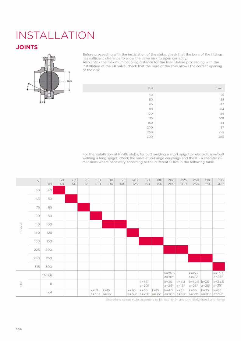
INSTALLATION
Before proceeding with the installation of the stubs, check that the bore of the fittings has sufficient clearance to allow the valve disk to open correctly. Also check the maximum coupling distance for the liner. Before proceeding with the installation of the FK valve, check that the bore of the stub allows the correct opening of the disk.
DN I min.
40 25
50 28
65 47
80 64
100 84
125 108
150 134
200 187
250 225
300 280
For the installation of PP-PE stubs, for butt welding a short spigot or electrofusion/butt welding a long spigot, check the valve-stub-flange couplings and the K - a chamfer di-mensions where necessary according to the different SDR's in the following table.
Short/long spigot stubs according to EN ISO 15494 and DIN 16962/16963 and flange
dDN
5040
6350
7565
9080
110100
125100
140125
160150
180150
200200
225200
250250
280250
315300
50 40
63 50
75 65
90 80
110 100
140 125
160 150
225 200
280 250
315 300
17/17.6k=26.5a=20°
k=15.7a=25°
k=13.3a=25°
11k=35a=20°
k=35a=25°
k=40a=15°
k=32.5a=25°
k=35a=25°
k=34.5a=25°
7.4k=10a=35°
k=15a=35°
k=20a=30°
k=35a=20°
k=15a=35°
k=40a=20°
k=35a=30°
k=55a=30°
k=35a=30°
k=65a=30°
FK
val
veS
DR
JOINTS
164

POSITIONING THE INSERTS
POS. 1
POS. 2
Place the inserts in the holes according to the positions indicated in the table, from the side corresponding to the letters D and DN in order to facilitate the insertion of the stud-bolts and the coupling with the flanges (DN 40 ÷ 200). The self-centring inserts must be inserted in the guides in the slots in the valve body on the side with the writing, with the writing facing upwards, and positioned according to the type of flange drilling, as indicated in the following table:
DN DIN 2501 PN6, EN 1092-1,
BS 4504 PN6, DIN 8063 PN6
DIN 2501 PN10/16, EN 1092-1, BS 4504 PN 10/16, DIN 8063
PN 10/16, EN ISO 15493
BS 10 table A-D-E
Spec D-E
BS 1560 cl.150,
ANSI B16.5 cl.150 *
JIS B 2220 K5
DN 40 Pos. 1 Pos. 2 Pos. 1 Pos. 1 Pos. 1
DN 50 Pos. 1 Pos. 2 Pos. 1 - N/A
DN 65 Pos. 1 Pos. 2 Pos. 1 Pos. 2 Pos. 1
DN 80 Pos. 1 Pos. 2 Pos. 1 Pos. 2 Pos. 1
DN 100 Pos. 1 Pos. 2 Pos. 1 Pos. 2 Pos. 1
DN 125 Pos. 1 Pos. 2 Pos. 1 Pos. 2 Pos. 1
DN 150 Pos. 1 Pos. 2 Pos. 1 Pos. 2 Pos. 1
DN 200 Pos. 1 PN 10 Pos. 2 Pos. 2 Pos. 2 Pos. 1
* DN 50 without inserts** DN 40, 50, 125 without inserts
POSITIONING THE VALVEPosition the valve between two flanged stubs, taking care to respect the installation tolerances Z. It is advisable to always install the valve with the disk partially closed (it must not exit the body) and avoid any misalignment of the flanges, as this would cause leaks.Where possible comply with the following requirements: - Conveying dirty fluids: position the valve with the stem inclined at an angle of 45° to the pipe support plane.- Conveying fluids with sediment: position the valve with the stem parallel to the pipe support plane.- Conveying clean fluids: position the valve with the stem perpendicular to the pipe support plane.
165
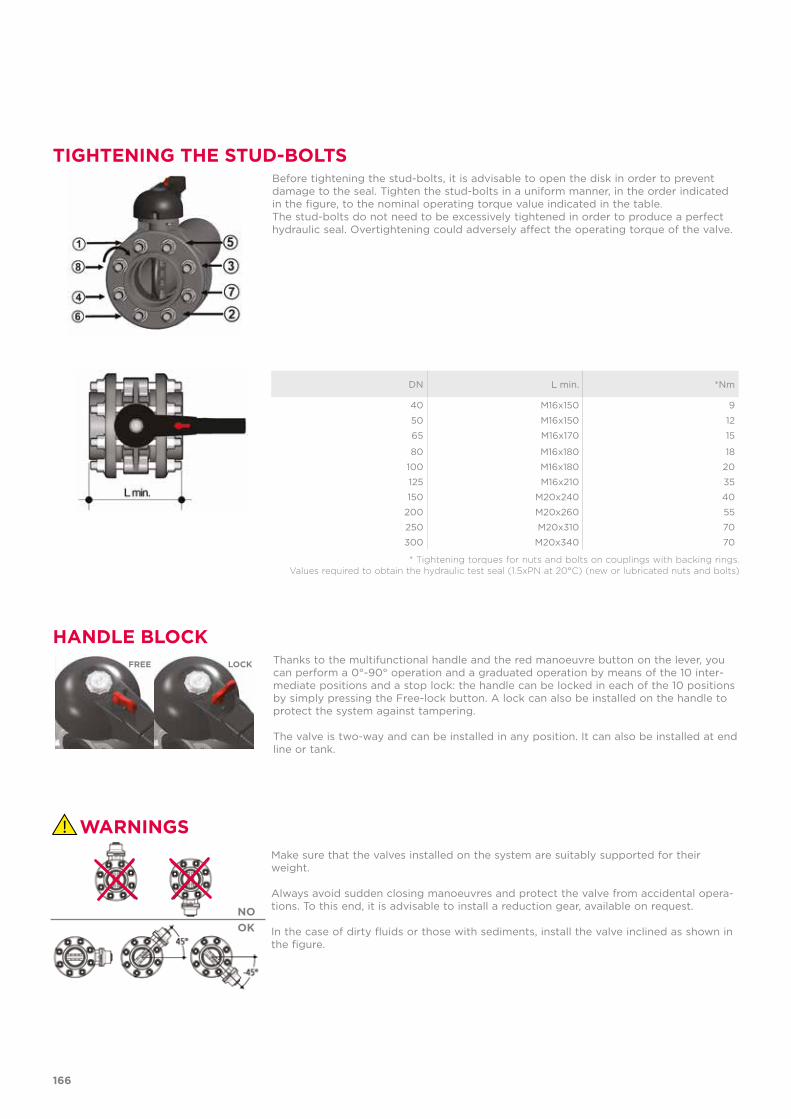
TIGHTENING THE STUD-BOLTSBefore tightening the stud-bolts, it is advisable to open the disk in order to prevent damage to the seal. Tighten the stud-bolts in a uniform manner, in the order indicated in the figure, to the nominal operating torque value indicated in the table. The stud-bolts do not need to be excessively tightened in order to produce a perfect hydraulic seal. Overtightening could adversely affect the operating torque of the valve.
* Tightening torques for nuts and bolts on couplings with backing rings. Values required to obtain the hydraulic test seal (1.5xPN at 20°C) (new or lubricated nuts and bolts)
DN L min. *Nm
40 M16x150 9
50 M16x150 12
65 M16x170 15
80 M16x180 18
100 M16x180 20
125 M16x210 35
150 M20x240 40
200 M20x260 55
250 M20x310 70
300 M20x340 70
HANDLE BLOCK
WARNINGS
Thanks to the multifunctional handle and the red manoeuvre button on the lever, you can perform a 0°-90° operation and a graduated operation by means of the 10 inter-mediate positions and a stop lock: the handle can be locked in each of the 10 positions by simply pressing the Free-lock button. A lock can also be installed on the handle to protect the system against tampering.
The valve is two-way and can be installed in any position. It can also be installed at end line or tank.
Make sure that the valves installed on the system are suitably supported for their weight.
Always avoid sudden closing manoeuvres and protect the valve from accidental opera-tions. To this end, it is advisable to install a reduction gear, available on request.
In the case of dirty fluids or those with sediments, install the valve inclined as shown in the figure.
FREE LOCK
NOOK
166

167

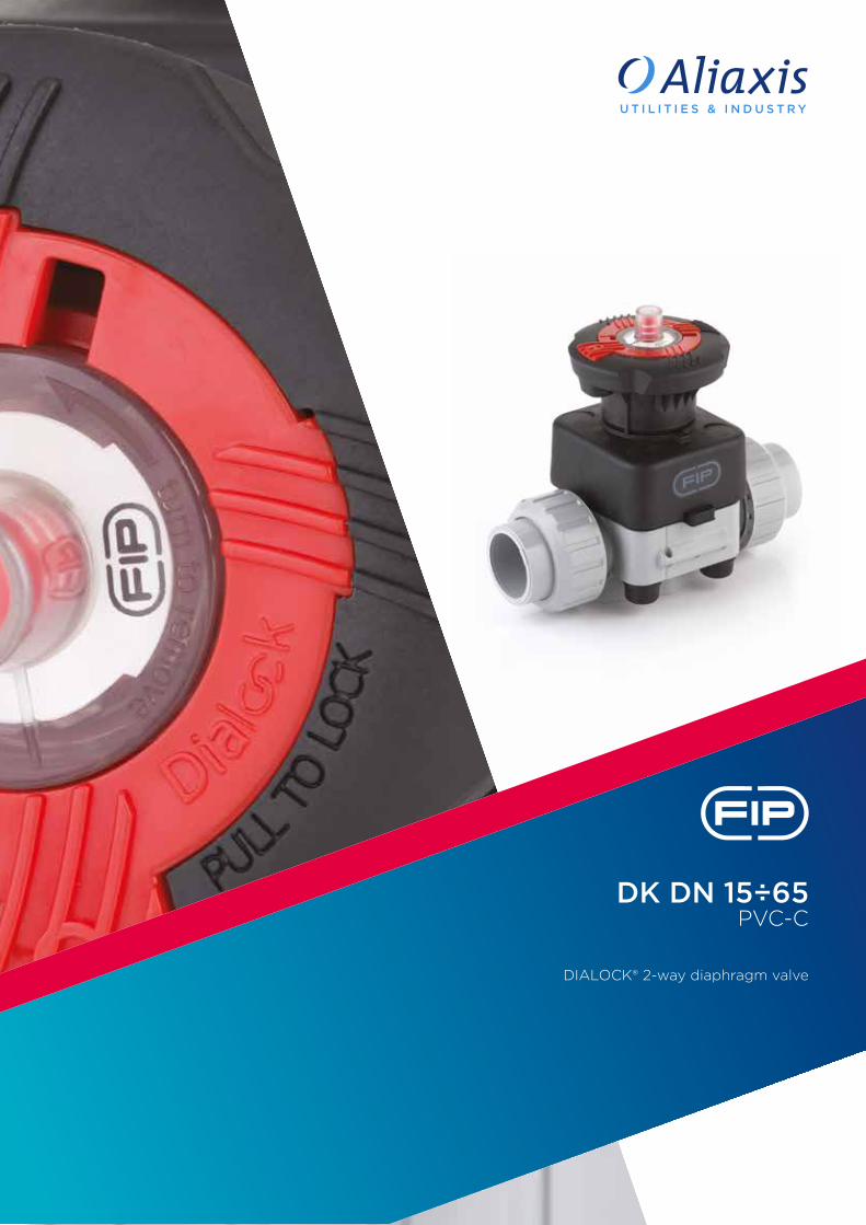
DK DN 15÷65 PVC-C
DIALOCK® 2-way diaphragm valve
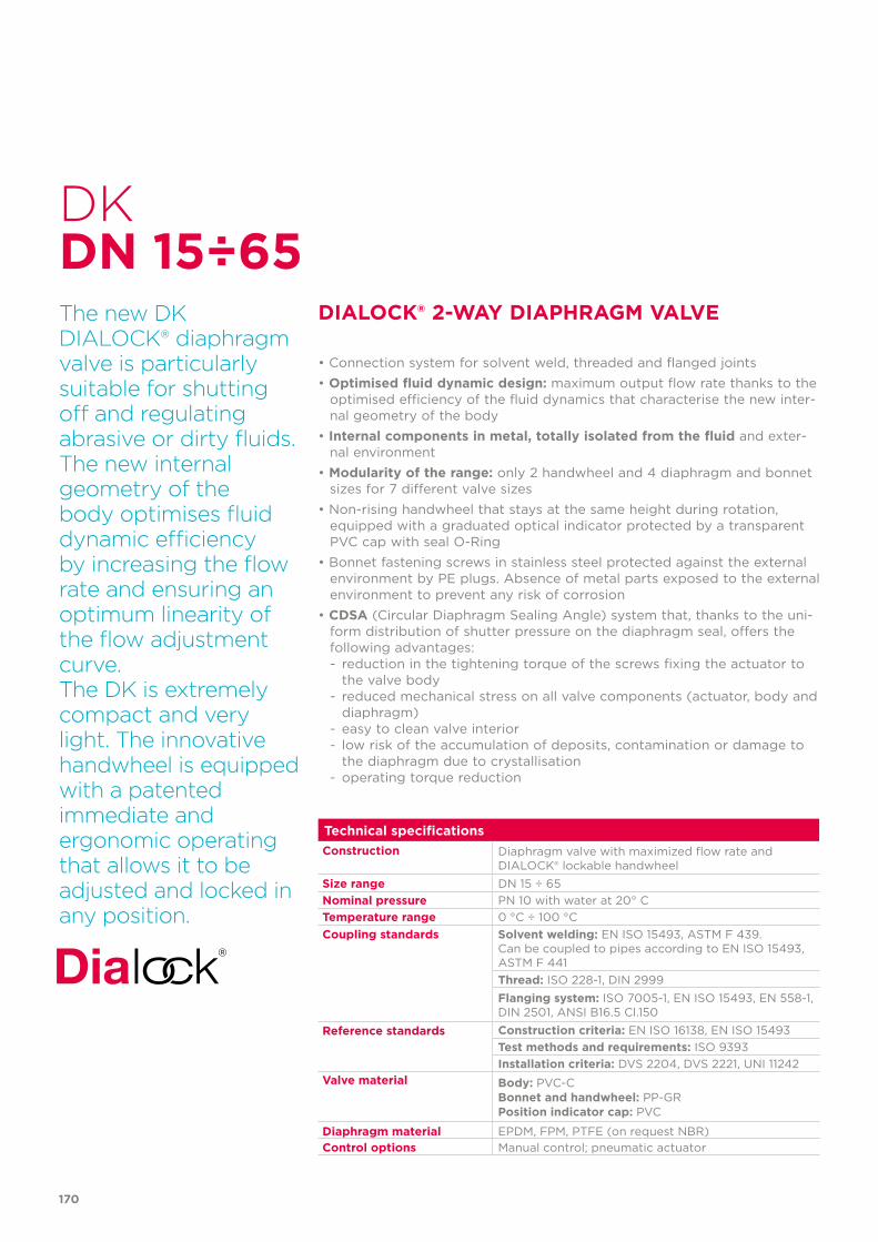
170
Technical specificationsConstruction Diaphragm valve with maximized flow rate and
DIALOCK® lockable handwheelSize range DN 15 ÷ 65Nominal pressure PN 10 with water at 20° CTemperature range 0 °C ÷ 100 °CCoupling standards Solvent welding: EN ISO 15493, ASTM F 439.
Can be coupled to pipes according to EN ISO 15493, ASTM F 441Thread: ISO 228-1, DIN 2999 Flanging system: ISO 7005-1, EN ISO 15493, EN 558-1,DIN 2501, ANSI B16.5 Cl.150
Reference standards Construction criteria: EN ISO 16138, EN ISO 15493Test methods and requirements: ISO 9393Installation criteria: DVS 2204, DVS 2221, UNI 11242
Valve material Body: PVC-CBonnet and handwheel: PP-GRPosition indicator cap: PVC
Diaphragm material EPDM, FPM, PTFE (on request NBR)Control options Manual control; pneumatic actuator
DK
The new DK DIALOCK® diaphragm valve is particularly suitable for shutting off and regulating abrasive or dirty fluids. The new internal geometry of the body optimises fluid dynamic efficiency by increasing the flow rate and ensuring an optimum linearity of the flow adjustment curve. The DK is extremely compact and very light. The innovative handwheel is equipped with a patented immediate and ergonomic operating that allows it to be adjusted and locked in any position.
DIALOCK® 2-WAY DIAPHRAGM VALVE
• Connection system for solvent weld, threaded and flanged joints • Optimised fluid dynamic design: maximum output flow rate thanks to the
optimised efficiency of the fluid dynamics that characterise the new inter-nal geometry of the body
• Internal components in metal, totally isolated from the fluid and exter-nal environment
• Modularity of the range: only 2 handwheel and 4 diaphragm and bonnet sizes for 7 different valve sizes
• Non-rising handwheel that stays at the same height during rotation, equipped with a graduated optical indicator protected by a transparent PVC cap with seal O-Ring
• Bonnet fastening screws in stainless steel protected against the external environment by PE plugs. Absence of metal parts exposed to the external environment to prevent any risk of corrosion
• CDSA (Circular Diaphragm Sealing Angle) system that, thanks to the uni-form distribution of shutter pressure on the diaphragm seal, offers the following advantages:- reduction in the tightening torque of the screws fixing the actuator to
the valve body- reduced mechanical stress on all valve components (actuator, body and
diaphragm)- easy to clean valve interior- low risk of the accumulation of deposits, contamination or damage to
the diaphragm due to crystallisation- operating torque reduction
DN 15÷65
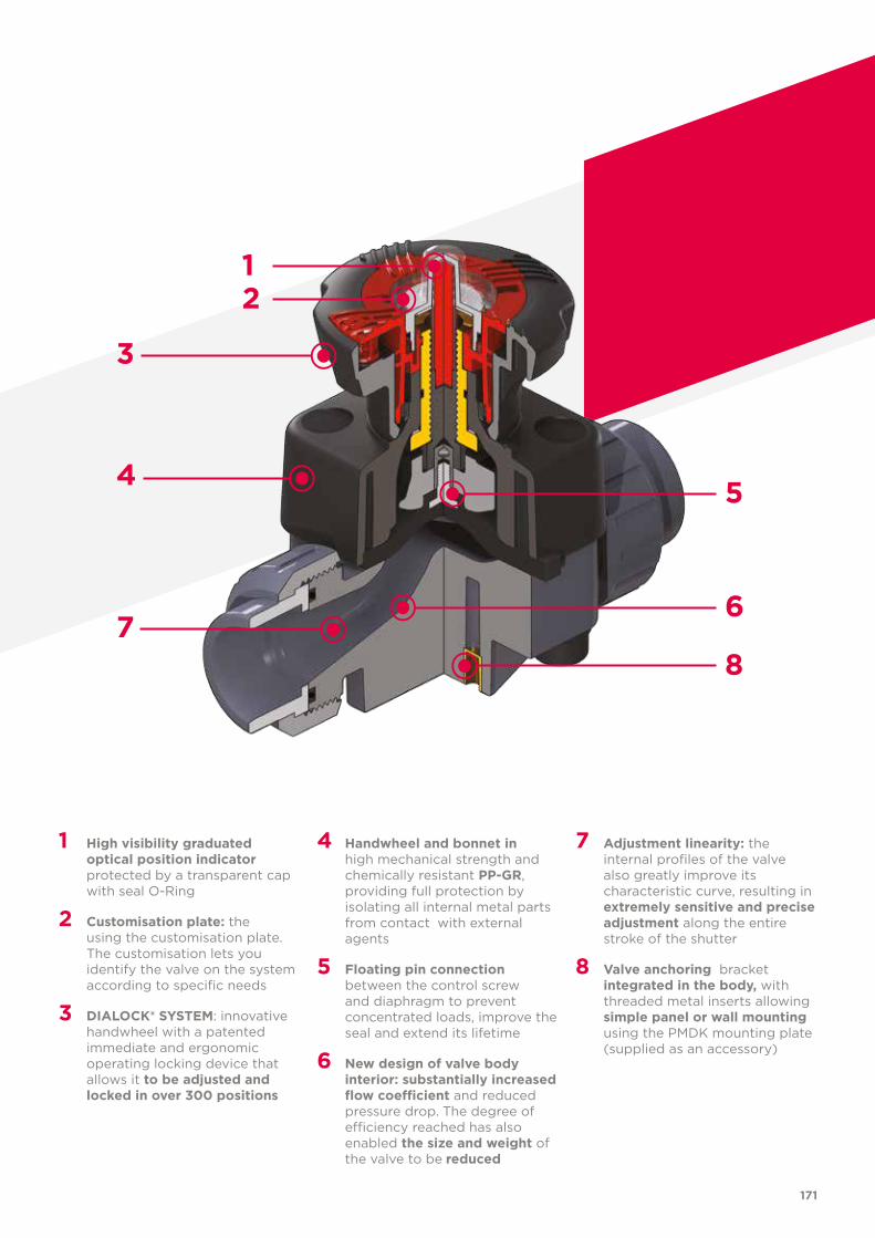
171
1 High visibility graduated optical position indicator protected by a transparent cap with seal O-Ring
2 Customisation plate: the using the customisation plate. The customisation lets you identify the valve on the system according to specific needs
3 DIALOCK® SYSTEM: innovative handwheel with a patented immediate and ergonomic operating locking device that allows it to be adjusted and locked in over 300 positions
4 Handwheel and bonnet in high mechanical strength and chemically resistant PP-GR, providing full protection by isolating all internal metal parts from contact with external agents
5 Floating pin connection between the control screw and diaphragm to prevent concentrated loads, improve the seal and extend its lifetime
6 New design of valve body interior: substantially increased flow coefficient and reduced pressure drop. The degree of efficiency reached has also enabled the size and weight of the valve to be reduced
7 Adjustment linearity: the internal profiles of the valve also greatly improve its characteristic curve, resulting in extremely sensitive and precise adjustment along the entire stroke of the shutter
8 Valve anchoring bracket integrated in the body, with threaded metal inserts allowing simple panel or wall mounting using the PMDK mounting plate (supplied as an accessory)
3
4
7
12
6
8
5
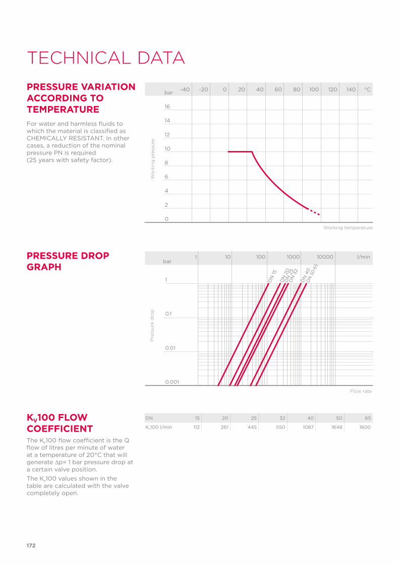
172
TECHNICAL DATA
-40 -20 0 20 40 60 80 100 120 140 °C
16
14
12
10
8
6
4
2
0
Wo
rkin
g p
ress
ure
Working temperature
barPRESSURE VARIATION ACCORDING TO TEMPERATUREFor water and harmless fluids to which the material is classified as CHEMICALLY RESISTANT. In other cases, a reduction of the nominal pressure PN is required (25 years with safety factor).
DN 15 20 25 32 40 50 65
Kv100 l/min 112 261 445 550 1087 1648 1600
KV100 FLOW COEFFICIENTThe Kv100 flow coefficient is the Q flow of litres per minute of water at a temperature of 20°C that will generate ∆p= 1 bar pressure drop at a certain valve position.The Kv100 values shown in the table are calculated with the valve completely open.
Flow rate
PRESSURE DROP GRAPH
Pre
ssu
re d
rop
bar1 10 100 1000 10000 l/min
1
0.1
0.01
0.001
DN
15D
N 2
0D
N 2
5D
N 3
2D
N 4
0D
N 5
0-65
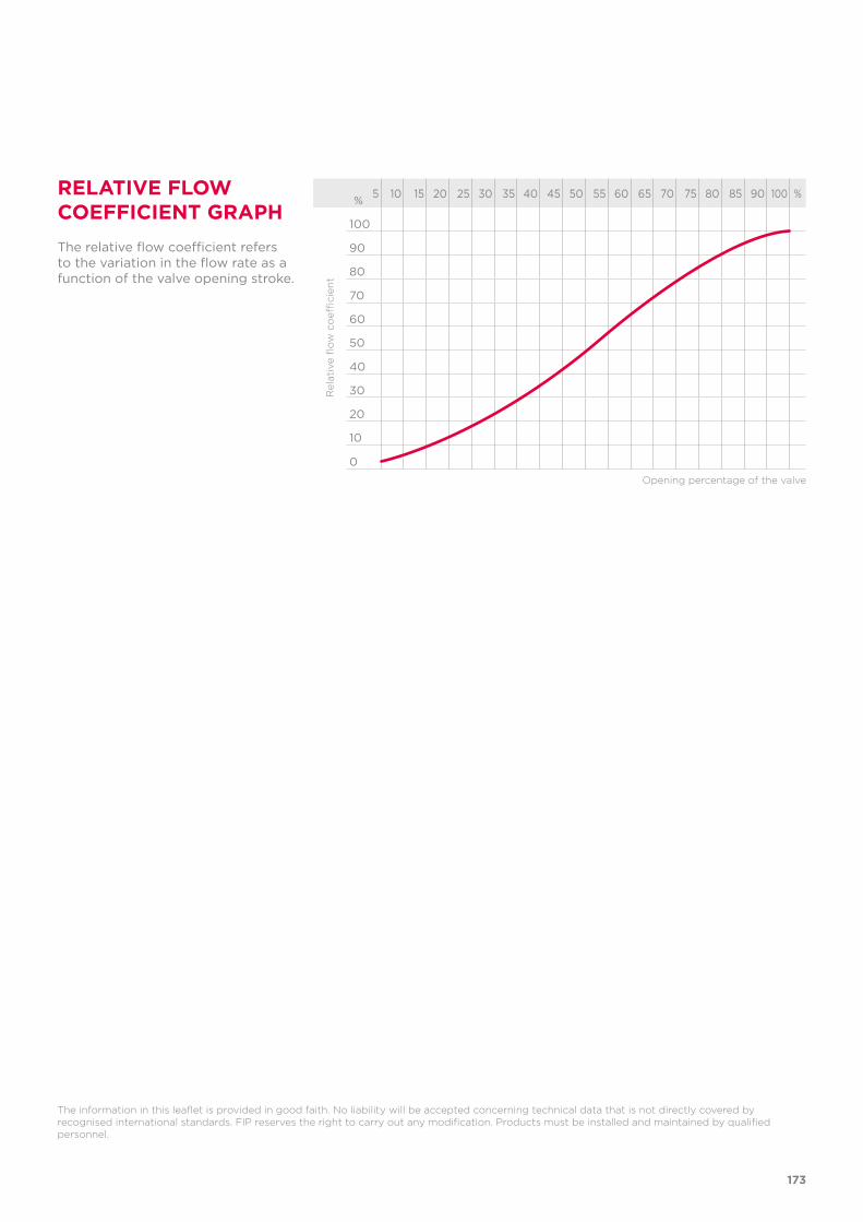
173
5 10 15 20 25 30 35 40 45 50 55 60 65 70 75 80 85 90 100 %
100
90
80
70
60
50
40
30
20
10
0
%
The relative flow coefficient refers to the variation in the flow rate as a function of the valve opening stroke.
The information in this leaflet is provided in good faith. No liability will be accepted concerning technical data that is not directly covered by recognised international standards. FIP reserves the right to carry out any modification. Products must be installed and maintained by qualified personnel.
RELATIVE FLOW COEFFICIENT GRAPH
Rel
ativ
e fl
ow
co
effici
ent
Opening percentage of the valve
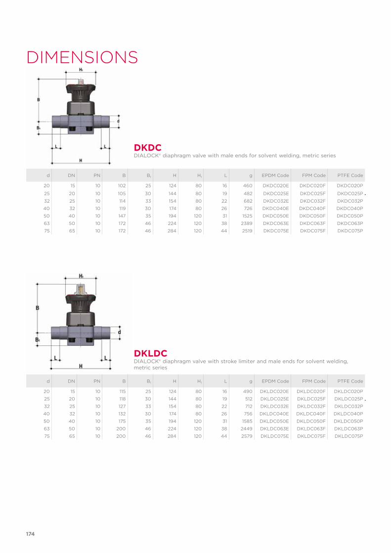
174
DIMENSIONS
d DN PN B B1 H H1 L g EPDM Code FPM Code PTFE Code
20 15 10 102 25 124 80 16 460 DKDC020E DKDC020F DKDC020P
25 20 10 105 30 144 80 19 482 DKDC025E DKDC025F DKDC025P
32 25 10 114 33 154 80 22 682 DKDC032E DKDC032F DKDC032P
40 32 10 119 30 174 80 26 726 DKDC040E DKDC040F DKDC040P
50 40 10 147 35 194 120 31 1525 DKDC050E DKDC050F DKDC050P
63 50 10 172 46 224 120 38 2389 DKDC063E DKDC063F DKDC063P
75 65 10 172 46 284 120 44 2519 DKDC075E DKDC075F DKDC075P
DKDCDIALOCK® diaphragm valve with male ends for solvent welding, metric series
d DN PN B B1 H H1 L g EPDM Code FPM Code PTFE Code
20 15 10 115 25 124 80 16 490 DKLDC020E DKLDC020F DKLDC020P
25 20 10 118 30 144 80 19 512 DKLDC025E DKLDC025F DKLDC025P
32 25 10 127 33 154 80 22 712 DKLDC032E DKLDC032F DKLDC032P
40 32 10 132 30 174 80 26 756 DKLDC040E DKLDC040F DKLDC040P
50 40 10 175 35 194 120 31 1585 DKLDC050E DKLDC050F DKLDC050P
63 50 10 200 46 224 120 38 2449 DKLDC063E DKLDC063F DKLDC063P
75 65 10 200 46 284 120 44 2579 DKLDC075E DKLDC075F DKLDC075P
DKLDCDIALOCK® diaphragm valve with stroke limiter and male ends for solvent welding, metric series
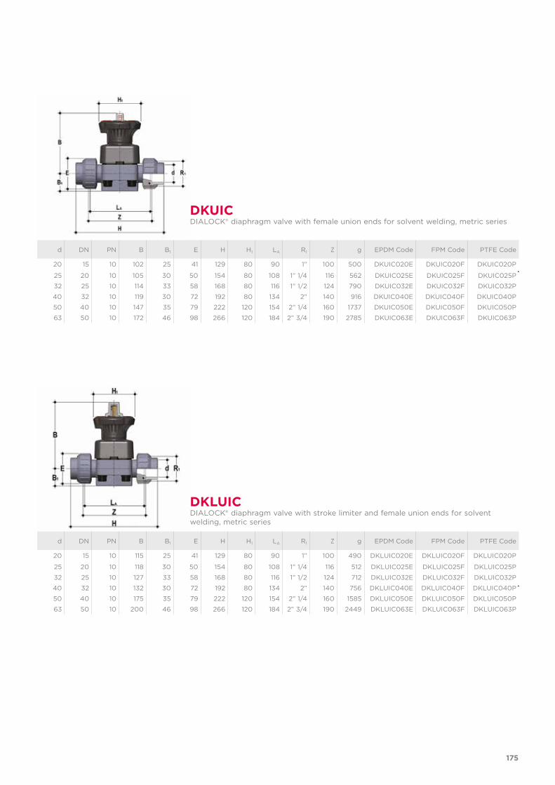
175
d DN PN B B1 E H H1 LA R1 Z g EPDM Code FPM Code PTFE Code
20 15 10 102 25 41 129 80 90 1” 100 500 DKUIC020E DKUIC020F DKUIC020P
25 20 10 105 30 50 154 80 108 1” 1/4 116 562 DKUIC025E DKUIC025F DKUIC025P
32 25 10 114 33 58 168 80 116 1” 1/2 124 790 DKUIC032E DKUIC032F DKUIC032P
40 32 10 119 30 72 192 80 134 2” 140 916 DKUIC040E DKUIC040F DKUIC040P
50 40 10 147 35 79 222 120 154 2” 1/4 160 1737 DKUIC050E DKUIC050F DKUIC050P
63 50 10 172 46 98 266 120 184 2” 3/4 190 2785 DKUIC063E DKUIC063F DKUIC063P
DKUICDIALOCK® diaphragm valve with female union ends for solvent welding, metric series
DKLUIC DIALOCK® diaphragm valve with stroke limiter and female union ends for solvent welding, metric series
d DN PN B B1 E H H1 LA R1 Z g EPDM Code FPM Code PTFE Code
20 15 10 115 25 41 129 80 90 1” 100 490 DKLUIC020E DKLUIC020F DKLUIC020P
25 20 10 118 30 50 154 80 108 1” 1/4 116 512 DKLUIC025E DKLUIC025F DKLUIC025P
32 25 10 127 33 58 168 80 116 1” 1/2 124 712 DKLUIC032E DKLUIC032F DKLUIC032P
40 32 10 132 30 72 192 80 134 2” 140 756 DKLUIC040E DKLUIC040F DKLUIC040P
50 40 10 175 35 79 222 120 154 2” 1/4 160 1585 DKLUIC050E DKLUIC050F DKLUIC050P
63 50 10 200 46 98 266 120 184 2” 3/4 190 2449 DKLUIC063E DKLUIC063F DKLUIC063P
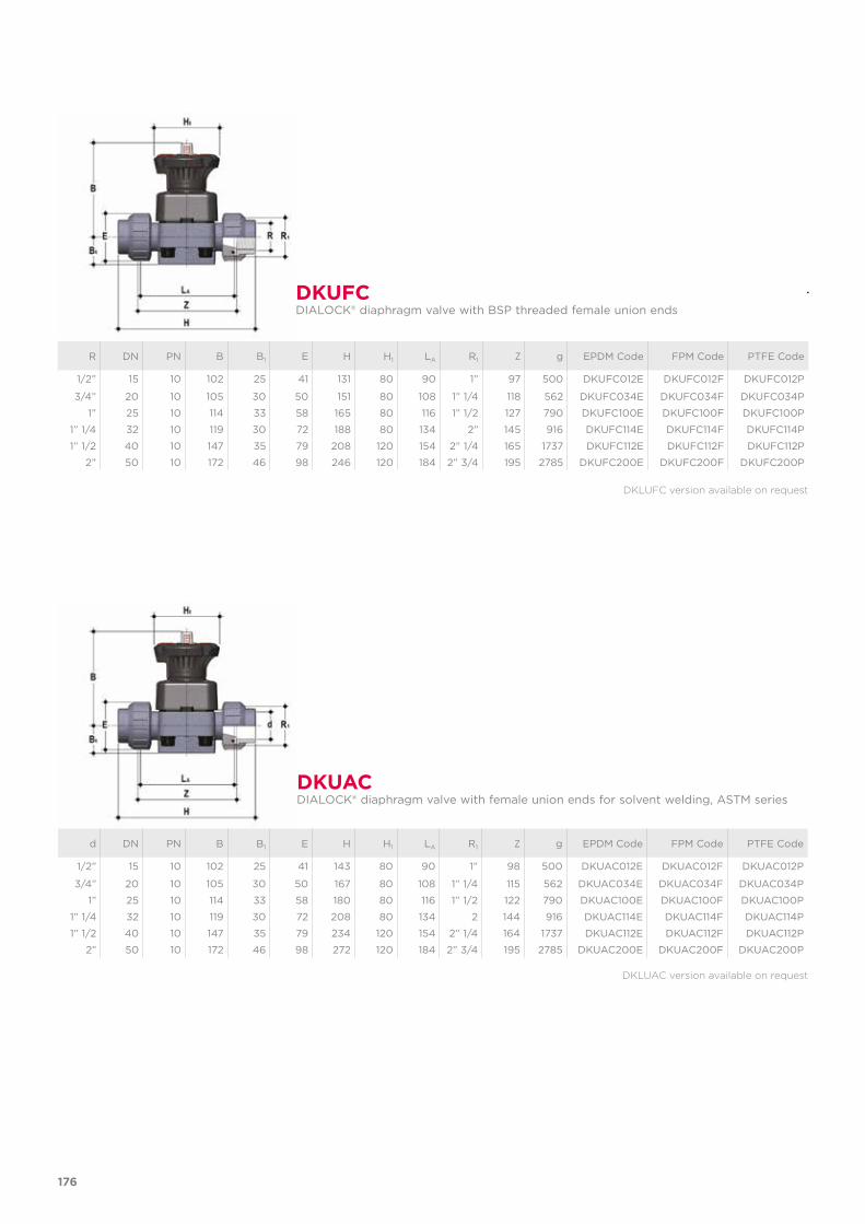
176
R DN PN B B1 E H H1 LA R1 Z g EPDM Code FPM Code PTFE Code
1/2” 15 10 102 25 41 131 80 90 1” 97 500 DKUFC012E DKUFC012F DKUFC012P
3/4” 20 10 105 30 50 151 80 108 1” 1/4 118 562 DKUFC034E DKUFC034F DKUFC034P
1” 25 10 114 33 58 165 80 116 1” 1/2 127 790 DKUFC100E DKUFC100F DKUFC100P
1” 1/4 32 10 119 30 72 188 80 134 2” 145 916 DKUFC114E DKUFC114F DKUFC114P
1” 1/2 40 10 147 35 79 208 120 154 2” 1/4 165 1737 DKUFC112E DKUFC112F DKUFC112P
2” 50 10 172 46 98 246 120 184 2” 3/4 195 2785 DKUFC200E DKUFC200F DKUFC200P
DKUFCDIALOCK® diaphragm valve with BSP threaded female union ends
DKUACDIALOCK® diaphragm valve with female union ends for solvent welding, ASTM series
d DN PN B B1 E H H1 LA R1 Z g EPDM Code FPM Code PTFE Code
1/2” 15 10 102 25 41 143 80 90 1” 98 500 DKUAC012E DKUAC012F DKUAC012P
3/4” 20 10 105 30 50 167 80 108 1” 1/4 115 562 DKUAC034E DKUAC034F DKUAC034P
1” 25 10 114 33 58 180 80 116 1” 1/2 122 790 DKUAC100E DKUAC100F DKUAC100P
1” 1/4 32 10 119 30 72 208 80 134 2 144 916 DKUAC114E DKUAC114F DKUAC114P
1” 1/2 40 10 147 35 79 234 120 154 2” 1/4 164 1737 DKUAC112E DKUAC112F DKUAC112P
2” 50 10 172 46 98 272 120 184 2” 3/4 195 2785 DKUAC200E DKUAC200F DKUAC200P
DKLUFC version available on request
DKLUAC version available on request
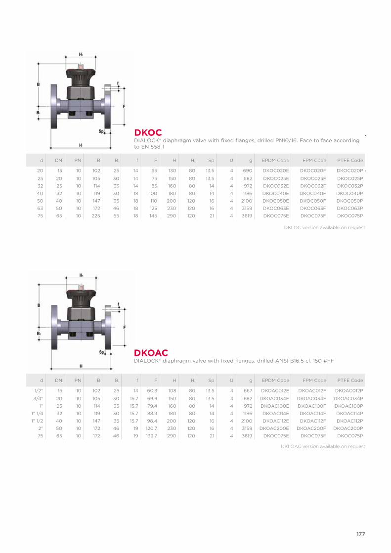
177
d DN PN B B1 f F H H1 Sp U g EPDM Code FPM Code PTFE Code
20 15 10 102 25 14 65 130 80 13.5 4 690 DKOC020E DKOC020F DKOC020P
25 20 10 105 30 14 75 150 80 13.5 4 682 DKOC025E DKOC025F DKOC025P
32 25 10 114 33 14 85 160 80 14 4 972 DKOC032E DKOC032F DKOC032P
40 32 10 119 30 18 100 180 80 14 4 1186 DKOC040E DKOC040F DKOC040P
50 40 10 147 35 18 110 200 120 16 4 2100 DKOC050E DKOC050F DKOC050P
63 50 10 172 46 18 125 230 120 16 4 3159 DKOC063E DKOC063F DKOC063P
75 65 10 225 55 18 145 290 120 21 4 3619 DKOC075E DKOC075F DKOC075P
DKOCDIALOCK® diaphragm valve with fixed flanges, drilled PN10/16. Face to face according to EN 558-1
DKLOC version available on request
DKOACDIALOCK® diaphragm valve with fixed flanges, drilled ANSI B16.5 cl. 150 #FF
DKLOAC version available on request
d DN PN B B1 f F H H1 Sp U g EPDM Code FPM Code PTFE Code
1/2” 15 10 102 25 14 60.3 108 80 13.5 4 667 DKOAC012E DKOAC012F DKOAC012P
3/4” 20 10 105 30 15.7 69.9 150 80 13.5 4 682 DKOAC034E DKOAC034F DKOAC034P
1” 25 10 114 33 15.7 79.4 160 80 14 4 972 DKOAC100E DKOAC100F DKOAC100P
1” 1/4 32 10 119 30 15.7 88.9 180 80 14 4 1186 DKOAC114E DKOAC114F DKOAC114P
1” 1/2 40 10 147 35 15.7 98.4 200 120 16 4 2100 DKOAC112E DKOAC112F DKOAC112P
2” 50 10 172 46 19 120.7 230 120 16 4 3159 DKOAC200E DKOAC200F DKOAC200P
75 65 10 172 46 19 139.7 290 120 21 4 3619 DKOC075E DKOC075F DKOC075P
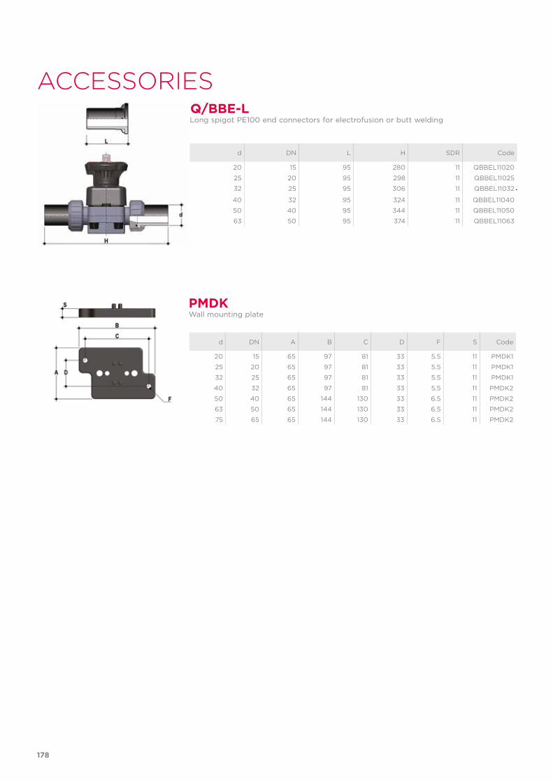
178
PMDK
d DN A B C D F S Code
20 15 65 97 81 33 5.5 11 PMDK1
25 20 65 97 81 33 5.5 11 PMDK1
32 25 65 97 81 33 5.5 11 PMDK1
40 32 65 97 81 33 5.5 11 PMDK2
50 40 65 144 130 33 6.5 11 PMDK2
63 50 65 144 130 33 6.5 11 PMDK2
75 65 65 144 130 33 6.5 11 PMDK2
Wall mounting plate
Q/BBE-LLong spigot PE100 end connectors for electrofusion or butt welding
d DN L H SDR Code
20 15 95 280 11 QBBEL11020
25 20 95 298 11 QBBEL11025
32 25 95 306 11 QBBEL11032
40 32 95 324 11 QBBEL11040
50 40 95 344 11 QBBEL11050
63 50 95 374 11 QBBEL11063
ACCESSORIES
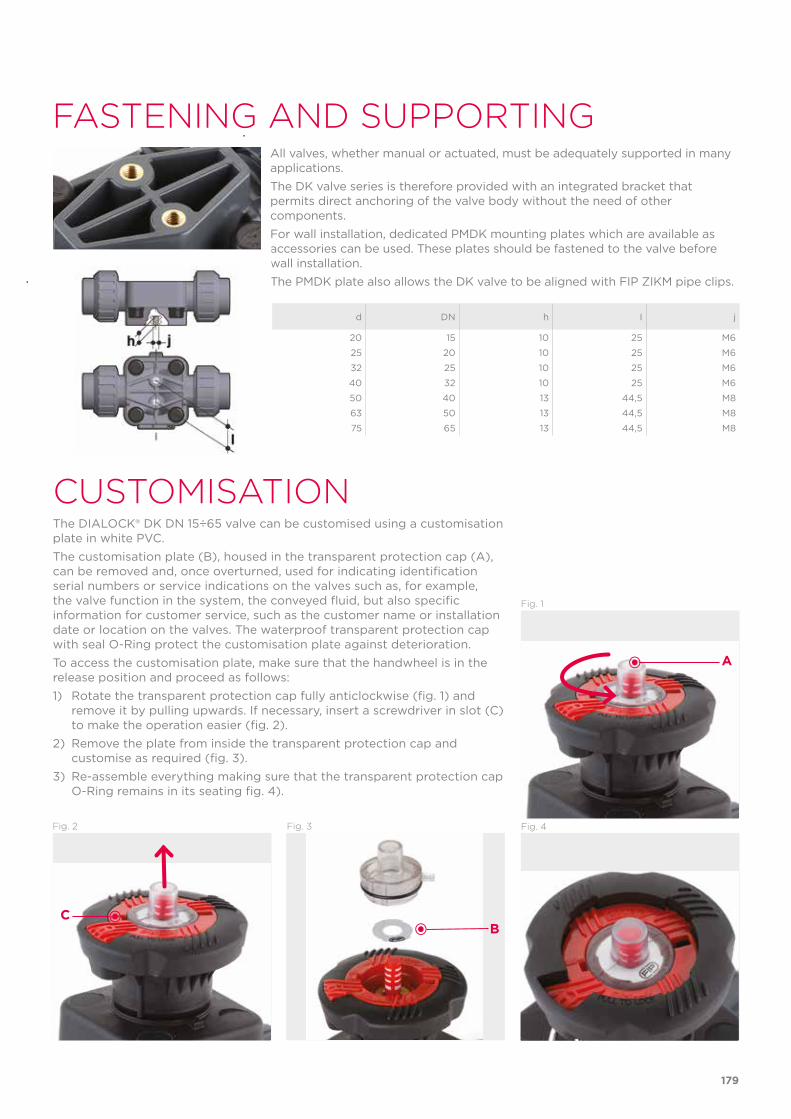
179
FASTENING AND SUPPORTINGAll valves, whether manual or actuated, must be adequately supported in many applications. The DK valve series is therefore provided with an integrated bracket that permits direct anchoring of the valve body without the need of other components.For wall installation, dedicated PMDK mounting plates which are available as accessories can be used. These plates should be fastened to the valve before wall installation. The PMDK plate also allows the DK valve to be aligned with FIP ZIKM pipe clips.
CUSTOMISATIONThe DIALOCK® DK DN 15÷65 valve can be customised using a customisation plate in white PVC. The customisation plate (B), housed in the transparent protection cap (A), can be removed and, once overturned, used for indicating identification serial numbers or service indications on the valves such as, for example, the valve function in the system, the conveyed fluid, but also specific information for customer service, such as the customer name or installation date or location on the valves. The waterproof transparent protection cap with seal O-Ring protect the customisation plate against deterioration.To access the customisation plate, make sure that the handwheel is in the release position and proceed as follows:1) Rotate the transparent protection cap fully anticlockwise (fig. 1) and
remove it by pulling upwards. If necessary, insert a screwdriver in slot (C) to make the operation easier (fig. 2).
2) Remove the plate from inside the transparent protection cap and customise as required (fig. 3).
3) Re-assemble everything making sure that the transparent protection cap O-Ring remains in its seating fig. 4).
Fig. 1
Fig. 2 Fig. 3 Fig. 4
BC
A
d DN h I j
20 15 10 25 M6
25 20 10 25 M6
32 25 10 25 M6
40 32 10 25 M6
50 40 13 44,5 M8
63 50 13 44,5 M8
75 65 13 44,5 M8
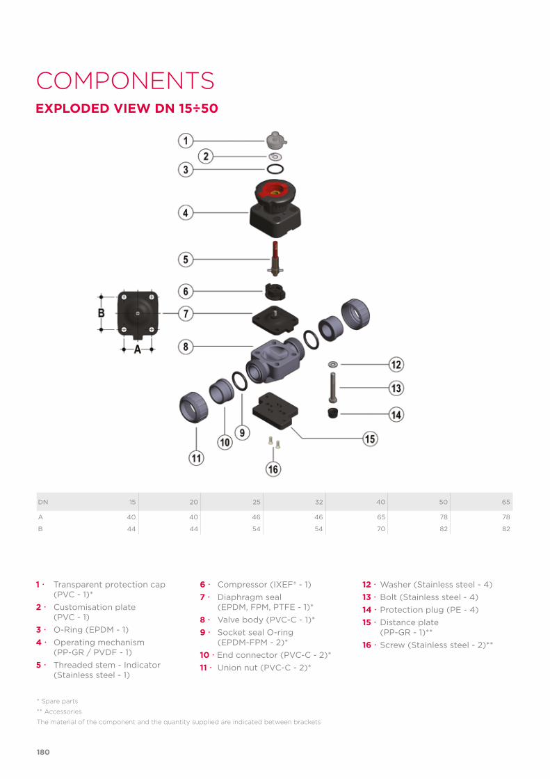
COMPONENTSEXPLODED VIEW DN 15÷50
180
DN 15 20 25 32 40 50 65
A 40 40 46 46 65 78 78
B 44 44 54 54 70 82 82
* Spare parts
** Accessories
The material of the component and the quantity supplied are indicated between brackets
1 Transparent protection cap (PVC - 1)*2 Customisation plate (PVC - 1)3 O-Ring (EPDM - 1)4 Operating mechanism (PP-GR / PVDF - 1) 5 Threaded stem - Indicator (Stainless steel - 1)
6 Compressor (IXEF® - 1)7 Diaphragm seal (EPDM, FPM, PTFE - 1)*8 Valve body (PVC-C - 1)*9 Socket seal O-ring (EPDM-FPM - 2)*10 End connector (PVC-C - 2)*11 Union nut (PVC-C - 2)*
12 Washer (Stainless steel - 4)13 Bolt (Stainless steel - 4)14 Protection plug (PE - 4)15 Distance plate (PP-GR - 1)**16 Screw (Stainless steel - 2)**
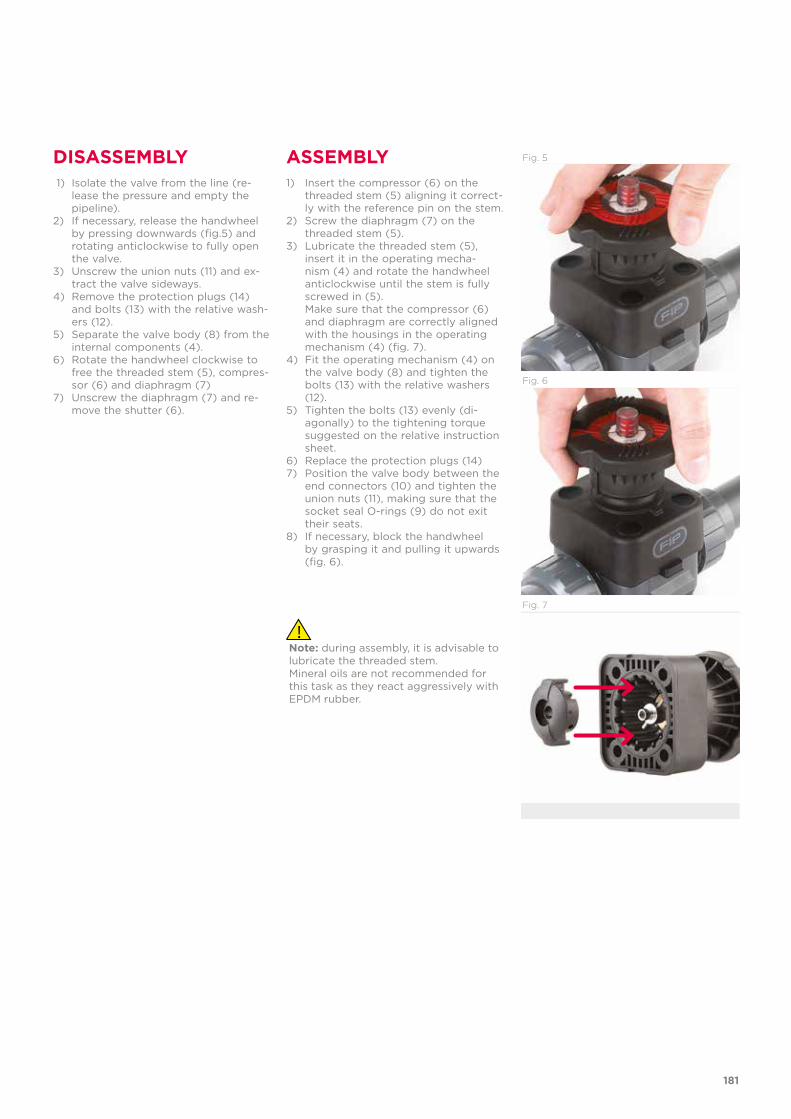
181
Fig. 5
Fig. 6
Fig. 7
DISASSEMBLY ASSEMBLY 1) Isolate the valve from the line (re-
lease the pressure and empty the pipeline).
2) If necessary, release the handwheel by pressing downwards (fig.5) and rotating anticlockwise to fully open the valve.
3) Unscrew the union nuts (11) and ex-tract the valve sideways.
4) Remove the protection plugs (14) and bolts (13) with the relative wash-ers (12).
5) Separate the valve body (8) from the internal components (4).
6) Rotate the handwheel clockwise to free the threaded stem (5), compres-sor (6) and diaphragm (7)
7) Unscrew the diaphragm (7) and re-move the shutter (6).
1) Insert the compressor (6) on the threaded stem (5) aligning it correct-ly with the reference pin on the stem.
2) Screw the diaphragm (7) on the threaded stem (5).
3) Lubricate the threaded stem (5), insert it in the operating mecha-nism (4) and rotate the handwheel anticlockwise until the stem is fully screwed in (5).
Make sure that the compressor (6) and diaphragm are correctly aligned with the housings in the operating mechanism (4) (fig. 7).
4) Fit the operating mechanism (4) on the valve body (8) and tighten the bolts (13) with the relative washers (12).
5) Tighten the bolts (13) evenly (di-agonally) to the tightening torque suggested on the relative instruction sheet.
6) Replace the protection plugs (14)7) Position the valve body between the
end connectors (10) and tighten the union nuts (11), making sure that the socket seal O-rings (9) do not exit their seats.
8) If necessary, block the handwheel by grasping it and pulling it upwards (fig. 6).
Note: during assembly, it is advisable to lubricate the threaded stem. Mineral oils are not recommended for this task as they react aggressively with EPDM rubber.
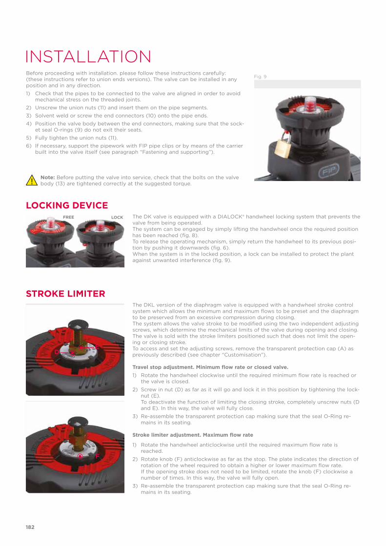
182
DE
F
Fig. 9
INSTALLATIONBefore proceeding with installation. please follow these instructions carefully: (these instructions refer to union ends versions). The valve can be installed in any position and in any direction.1) Check that the pipes to be connected to the valve are aligned in order to avoid
mechanical stress on the threaded joints.2) Unscrew the union nuts (11) and insert them on the pipe segments.3) Solvent weld or screw the end connectors (10) onto the pipe ends.4) Position the valve body between the end connectors, making sure that the sock-
et seal O-rings (9) do not exit their seats.5) Fully tighten the union nuts (11). 6) If necessary, support the pipework with FIP pipe clips or by means of the carrier
built into the valve itself (see paragraph “Fastening and supporting”).
LOCKING DEVICE
STROKE LIMITER
The DK valve is equipped with a DIALOCK® handwheel locking system that prevents the valve from being operated.The system can be engaged by simply lifting the handwheel once the required position has been reached (fig. 8).To release the operating mechanism, simply return the handwheel to its previous posi-tion by pushing it downwards (fig. 6).When the system is in the locked position, a lock can be installed to protect the plant against unwanted interference (fig. 9).
The DKL version of the diaphragm valve is equipped with a handwheel stroke control system which allows the minimum and maximum flows to be preset and the diaphragm to be preserved from an excessive compression during closing.The system allows the valve stroke to be modified using the two independent adjusting screws, which determine the mechanical limits of the valve during opening and closing. The valve is sold with the stroke limiters positioned such that does not limit the open-ing or closing stroke.To access and set the adjusting screws, remove the transparent protection cap (A) as previously described (see chapter “Customisation”).
Travel stop adjustment. Minimum flow rate or closed valve. 1) Rotate the handwheel clockwise until the required minimum flow rate is reached or
the valve is closed.
2) Screw in nut (D) as far as it will go and lock it in this position by tightening the lock-nut (E).
To deactivate the function of limiting the closing stroke, completely unscrew nuts (D and E). In this way, the valve will fully close.
3) Re-assemble the transparent protection cap making sure that the seal O-Ring re-mains in its seating.
Stroke limiter adjustment. Maximum flow rate
1) Rotate the handwheel anticlockwise until the required maximum flow rate is reached.
2) Rotate knob (F) anticlockwise as far as the stop. The plate indicates the direction of rotation of the wheel required to obtain a higher or lower maximum flow rate.
If the opening stroke does not need to be limited, rotate the knob (F) clockwise a number of times. In this way, the valve will fully open.
3) Re-assemble the transparent protection cap making sure that the seal O-Ring re-mains in its seating.
FREE LOCK
Note: Before putting the valve into service, check that the bolts on the valve body (13) are tightened correctly at the suggested torque.

183


VM DN 80÷100 PVC-C
Diaphragm valve
Technical specificationsConstruction Single wear diaphragm valveSize range DN 80 ÷ 100
Nominal pressure PN 10 with water at 20° CPN 6 with water at 20° C (PTFE version)
Temperature range 0 °C ÷ 100 °CCoupling standards Solvent welding: EN ISO 15493, ASTM F 439.
Can be coupled to pipes according to EN ISO 15493
Flanging system: ISO 7005-1, EN ISO 15493, EN 558-1, DIN 2501, ANSI B16.5 Cl.150
Reference standards Construction criteria: EN ISO 16138, EN ISO 15493Test methods and requirements: ISO 9393Installation criteria: DVS 2204, DVS 2221, UNI 11242
Valve material Body: PVC-CBonnet: PP-GRHandwheel: PA-GR
Diaphragm material EPDM, FPM, PTFE (on request NBR)Control options Manual control; pneumatic actuator
VM
The VM is particularly suitable for shutting off and regulating abrasive or dirty fluids. The handwheel control and diaphragm seal provide precise and effective control, while reducing the risk of water hammer to a minimum.
DIAPHRAGM VALVE
• Connection system for solvent weld, threaded and flanged joints• Compact and lightweight construction• High flow coefficient and minimum pressure drop• Internal components in metal totally isolated from the conveyed fluid,
with anti-friction disk to reduce friction to a minimum• Modularity of the range: only 5 diaphragm and bonnet sizes for 9 differ-
ent valve sizes• Handwheel that stays at the same height during rotation
DN 80÷100
186
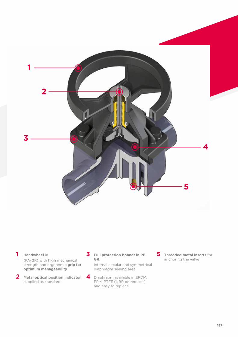
187
1 Handwheel in (PA-GR) with high mechanical
strength and ergonomic grip for optimum manageability
2 Metal optical position indicator supplied as standard
3 Full protection bonnet in PP-GR.
Internal circular and symmetrical diaphragm sealing area
4 Diaphragm available in EPDM, FPM, PTFE (NBR on request) and easy to replace
5 Threaded metal inserts for anchoring the valve
1
3
5
2
4
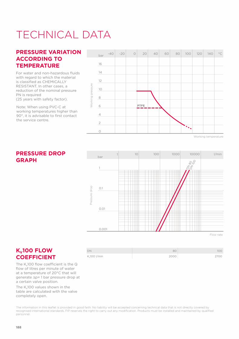
Note: When using PVC-C at working temperatures higher than 90°, it is advisable to first contact the service centre.
PTFE
188
TECHNICAL DATA
-40 -20 0 20 40 60 80 100 120 140 °C
16
14
12
10
8
6
4
2
0
Wo
rkin
g p
ress
ure
Working temperature
barPRESSURE VARIATION ACCORDING TO TEMPERATUREFor water and non-hazardous fluids with regard to which the material is classified as CHEMICALLY RESISTANT. In other cases, a reduction of the nominal pressure PN is required (25 years with safety factor).
KV100 FLOW COEFFICIENTThe Kv100 flow coefficient is the Q flow of litres per minute of water at a temperature of 20°C that will generate ∆p= 1 bar pressure drop at a certain valve position.The Kv100 values shown in the table are calculated with the valve completely open.
The information in this leaflet is provided in good faith. No liability will be accepted concerning technical data that is not directly covered by recognised international standards. FIP reserves the right to carry out any modification. Products must be installed and maintained by qualified personnel.
PRESSURE DROP GRAPH
bar1 10 100 1000 10000 l/min
1
0.1
0.01
0.001
DN
80
DN
100
Pre
ssu
re d
rop
Flow rate
DN 80 100
Kv100 l/min 2000 2700
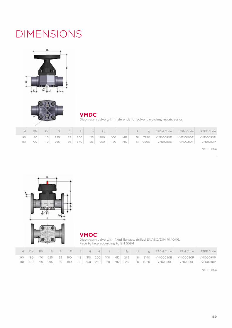
189
DIMENSIONS
d DN PN B B1 H h H1 I J L g EPDM Code FPM Code PTFE Code
90 80 *10 225 55 300 23 200 100 M12 51 7290 VMDC090E VMDC090F VMDC090P
110 100 *10 295 69 340 23 250 120 M12 61 10900 VMDC110E VMDC110F VMDC110P
VMDCDiaphragm valve with male ends for solvent welding, metric series
*PTFE PN6
d DN PN B B1 F f H H1 I J Sp U g EPDM Code FPM Code PTFE Code
90 80 *10 225 55 160 18 310 200 100 M12 21.5 8 9140 VMOC090E VMOC090F VMOC090P
110 100 *10 295 69 180 18 350 250 120 M12 22.5 8 13120 VMOC110E VMOC110F VMOC110P
VMOCDiaphragm valve with fixed flanges, drilled EN/ISO/DIN PN10/16.Face to face according to EN 558-1
*PTFE PN6
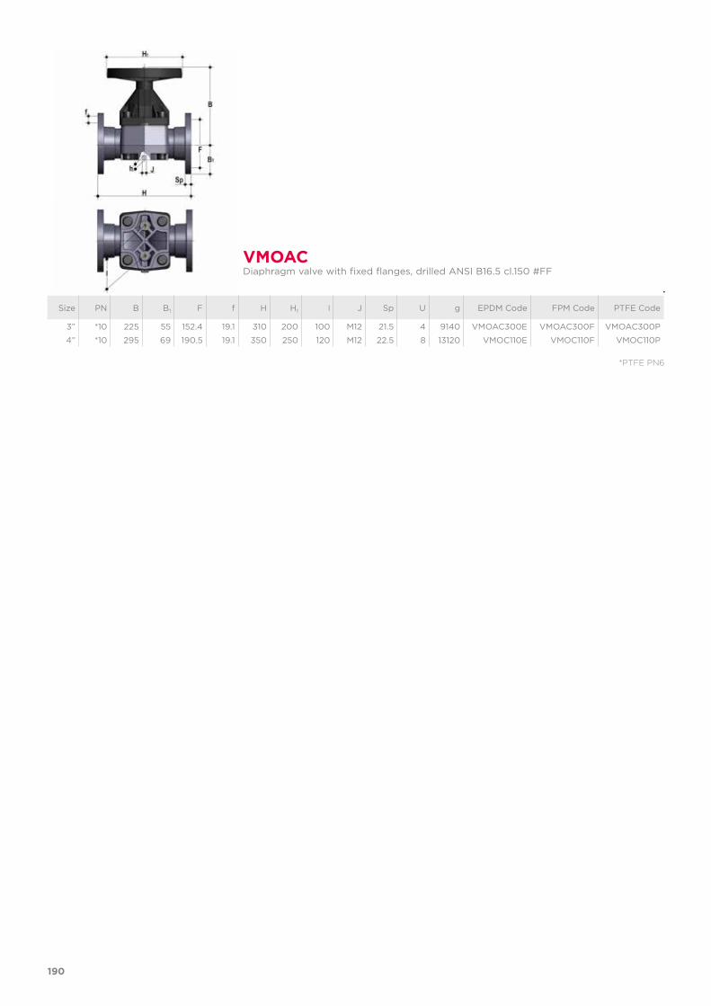
190
VMOACDiaphragm valve with fixed flanges, drilled ANSI B16.5 cl.150 #FF
Size PN B B1 F f H H1 I J Sp U g EPDM Code FPM Code PTFE Code
3” *10 225 55 152.4 19.1 310 200 100 M12 21.5 4 9140 VMOAC300E VMOAC300F VMOAC300P
4” *10 295 69 190.5 19.1 350 250 120 M12 22.5 8 13120 VMOC110E VMOC110F VMOC110P
*PTFE PN6

191
COMPONENTSEXPLODED VIEW
1 Bonnet (PP-GR - 1); Handwheel (PA-GR - 1)2 Indicator - stem (STAINLESS steel - 1)3 Shutter (PBT - 1)
4 Diaphragm (EPDM, FPM, PTFE - 1)5 Body (PVC-C - 1)6 Hexagonal screw (Zinc plated steel - 4)
7 Washer (Zinc plated steel - 4)8 Protection plug (PE - 4)9 Nut (Zinc plated steel - 4)
DN 100DN 80
DN 80 100
A 114 193
B 127 -
The material of the component and the quantity supplied are indicated in brackets.
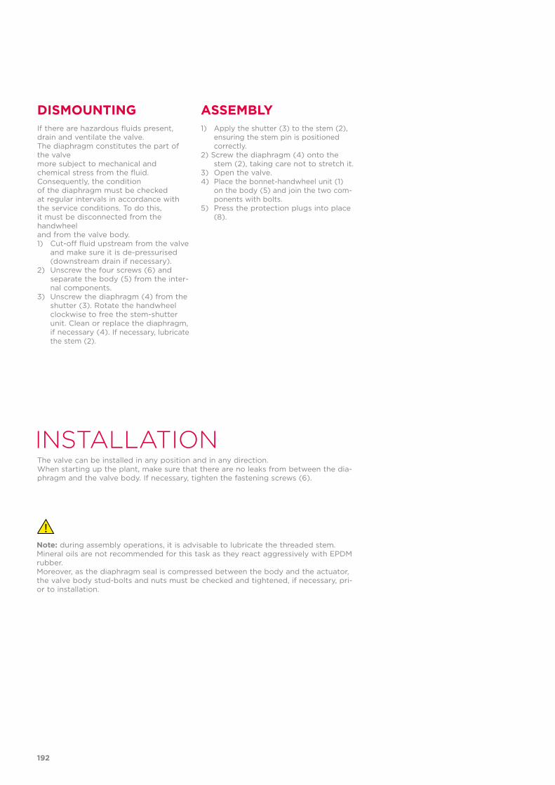
DISMOUNTING ASSEMBLYIf there are hazardous fluids present, drain and ventilate the valve.The diaphragm constitutes the part of the valvemore subject to mechanical andchemical stress from the fluid. Consequently, the conditionof the diaphragm must be checkedat regular intervals in accordance withthe service conditions. To do this,it must be disconnected from the handwheeland from the valve body.1) Cut-off fluid upstream from the valve
and make sure it is de-pressurised (downstream drain if necessary).
2) Unscrew the four screws (6) and separate the body (5) from the inter-nal components.
3) Unscrew the diaphragm (4) from the shutter (3). Rotate the handwheel clockwise to free the stem-shutter unit. Clean or replace the diaphragm, if necessary (4). If necessary, lubricate the stem (2).
1) Apply the shutter (3) to the stem (2), ensuring the stem pin is positioned correctly.
2) Screw the diaphragm (4) onto the stem (2), taking care not to stretch it.
3) Open the valve.4) Place the bonnet-handwheel unit (1)
on the body (5) and join the two com-ponents with bolts.
5) Press the protection plugs into place (8).
INSTALLATIONThe valve can be installed in any position and in any direction.When starting up the plant, make sure that there are no leaks from between the dia-phragm and the valve body. If necessary, tighten the fastening screws (6).
Note: during assembly operations, it is advisable to lubricate the threaded stem. Mineral oils are not recommended for this task as they react aggressively with EPDM rubber.Moreover, as the diaphragm seal is compressed between the body and the actuator, the valve body stud-bolts and nuts must be checked and tightened, if necessary, pri-or to installation.
192

193

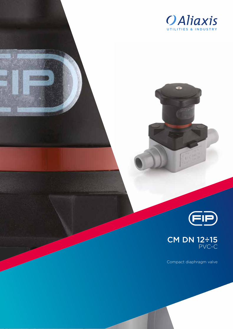
CM DN 12÷15PVC-C
Compact diaphragm valve
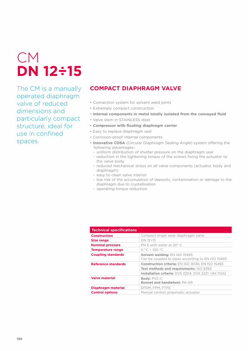
Technical specificationsConstruction Compact single wear diaphragm valveSize range DN 12÷15Nominal pressure PN 6 with water at 20° CTemperature range 0 °C ÷ 100 °CCoupling standards Solvent welding: EN ISO 15493.
Can be coupled to pipes according to EN ISO 15493
Reference standards Construction criteria: EN ISO 16138, EN ISO 15493Test methods and requirements: ISO 9393Installation criteria: DVS 2204, DVS 2221, UNI 11242
Valve material Body: PVC-CBonnet and handwheel: PA-GR
Diaphragm material EPDM, FPM, PTFEControl options Manual control; pneumatic actuator
CM
The CM is a manually operated diaphragm valve of reduced dimensions and particularly compact structure, ideal for use in confined spaces.
COMPACT DIAPHRAGM VALVE
• Connection system for solvent weld joints• Extremely compact construction• Internal components in metal totally isolated from the conveyed fluid• Valve stem in STAINLESS steel • Compressor with floating diaphragm carrier• Easy to replace diaphragm seal• Corrosion-proof internal components• Innovative CDSA (Circular Diaphragm Sealing Angle) system offering the
following advantages::- uniform distribution of shutter pressure on the diaphragm seal- reduction in the tightening torque of the screws fixing the actuator to
the valve body- reduced mechanical stress on all valve components (actuator, body and
diaphragm)- easy to clean valve interior- low risk of the accumulation of deposits, contamination or damage to the
diaphragm due to crystallisation- operating torque reduction
DN 12÷15
196
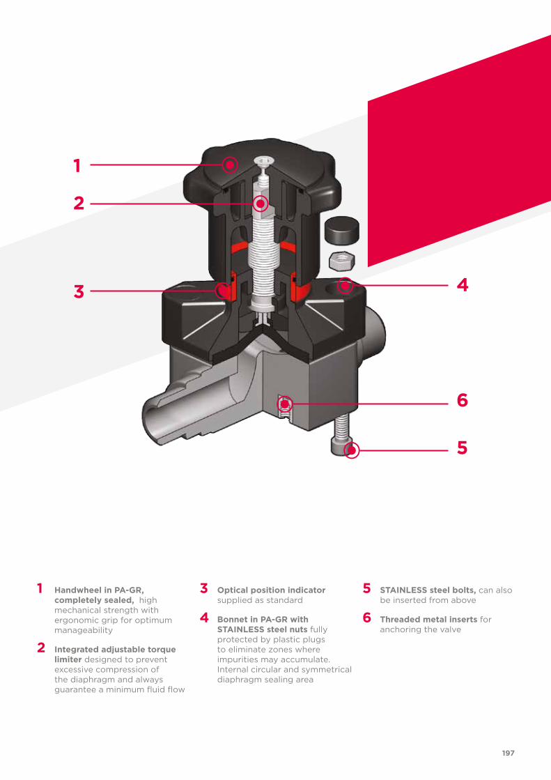
1 Handwheel in PA-GR, completely sealed, high mechanical strength with ergonomic grip for optimum manageability
2 Integrated adjustable torque limiter designed to prevent excessive compression of the diaphragm and always guarantee a minimum fluid flow
3 Optical position indicator supplied as standard
4 Bonnet in PA-GR with STAINLESS steel nuts fully protected by plastic plugs to eliminate zones where impurities may accumulate. Internal circular and symmetrical diaphragm sealing area
5 STAINLESS steel bolts, can also be inserted from above
6 Threaded metal inserts for anchoring the valve
1
2
3
6
5
4
197
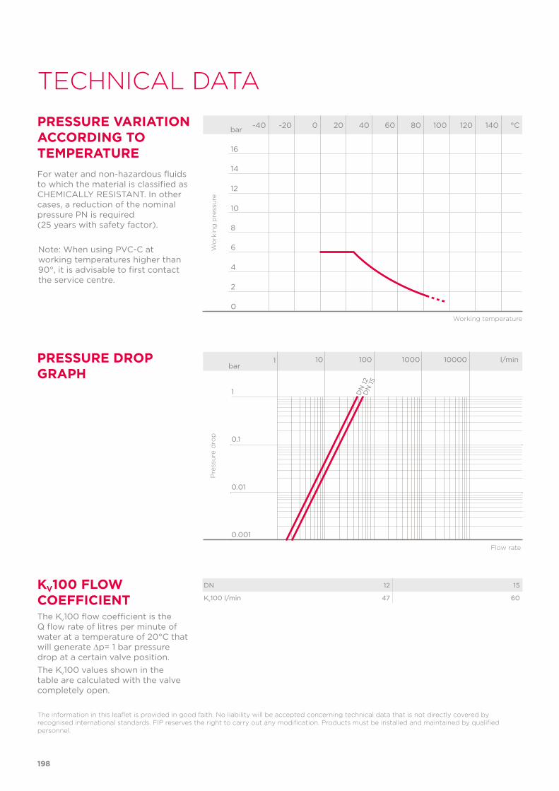
Note: When using PVC-C at working temperatures higher than 90°, it is advisable to first contact the service centre.
198
TECHNICAL DATA
-40 -20 0 20 40 60 80 100 120 140 °C
16
14
12
10
8
6
4
2
0
Wo
rkin
g p
ress
ure
Working temperature
barPRESSURE VARIATION ACCORDING TO TEMPERATUREFor water and non-hazardous fluids to which the material is classified as CHEMICALLY RESISTANT. In other cases, a reduction of the nominal pressure PN is required (25 years with safety factor).
DN 12 15
Kv100 l/min 47 60
KV100 FLOW COEFFICIENTThe Kv100 flow coefficient is the Q flow rate of litres per minute of water at a temperature of 20°C that will generate ∆p= 1 bar pressure drop at a certain valve position.The Kv100 values shown in the table are calculated with the valve completely open.
The information in this leaflet is provided in good faith. No liability will be accepted concerning technical data that is not directly covered by recognised international standards. FIP reserves the right to carry out any modification. Products must be installed and maintained by qualified personnel.
PRESSURE DROP GRAPH
bar1 10 100 1000 10000 l/min
1
0.1
0.01
0.001
DN
12D
N 15
Pre
ssu
re d
rop
Flow rate
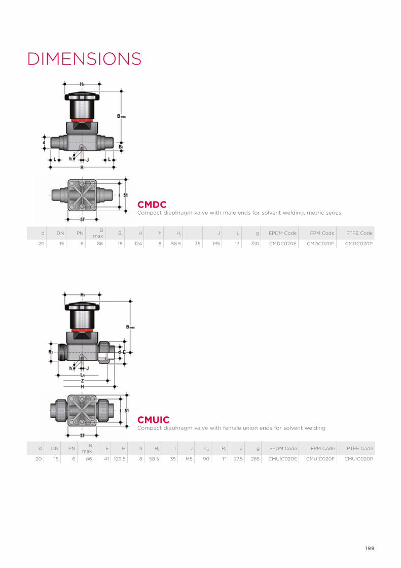
199
d DN PN B max B1 H h H1 I J L g EPDM Code FPM Code PTFE Code
20 15 6 86 15 124 8 58.5 35 M5 17 310 CMDC020E CMDC020F CMDC020P
CMDCCompact diaphragm valve with male ends for solvent welding, metric series
DIMENSIONS
d DN PN B max E H h H1 I J LA R1 Z g EPDM Code FPM Code PTFE Code
20 15 6 86 41 129.5 8 58.5 35 M5 90 1” 97.5 285 CMUIC020E CMUIC020F CMUIC020P
CMUICCompact diaphragm valve with female union ends for solvent welding

200
The material of the component and the quantity supplied are indicated between brackets
COMPONENTSEXPLODED VIEW
1 Body (PVC-C - 1)2 Diaphragm seal (EPDM, FPM, PTFE - 1)5 Fastening screw (STAINLESS steel - 4)6 Washer (STAINLESS steel - 4)7 Shutter (PA-GR - 1)
8 Nut (STAINLESS steel - 1)9 Stem (STAINLESS steel - 1)10 Bonnet (PA-GR - 1)13 Nut (STAINLESS steel - 4)14 Protection plug (POM - 4)15 Optical position indicator (PVDF - 1)
22 O-Ring (NBR - 1)23 Handwheel (PA-GR - 1)24 O-Ring (NBR - 1)25 Bonnet (PA-GR - 1)26 Fastening screw (STAINLESS steel - 1)
DISASSEMBLY ASSEMBLYIf the valve is already installed on the line, shut-off the fluid flow upstream and make sure that there is no pressure. If necessary, fully drain the system down-stream. If there are hazardous fluids pre-sent, drain and ventilate the valve.The diaphragm constitutes the part of the valve more subject to mechani-cal and chemical stress from the fluid. Consequently, the condition of the diaphragm must be checked at regular intervals in accordance with the service conditions. To do this, it must be discon-nected from the handwheel and from the valve body.1) Unscrew the four screws (5) and
separate the body (1) from the inter-nal components.
2) Unscrew the diaphragm (2) from the shutter (7).
3) If necessary, clean or replace the dia-phragm (2).
4) If necessary, lubricate the stem (9).
1) The diaphragm seal (2) must be screwed fully into the compressor (7) in a clockwise direction. If necessary, unscrew slightly in an anticlockwise direction to line up the screw holes.
2) Fix the bonnet (10) to the body (1) using screws (5). Tighten the screws, making sure not to over-compress the diaphragm.
INSTALLATIONThe valve can be installed in any position and in any direction.When starting up the plant, make sure that there are no leaks from between the dia-phragm and the valve body. If necessary, tighten the fastening screws (5).
SETTINGThe valve is factory set to guarantee a permanent seal without requiring any further intervention. To adjust the setting, rotate the handwheel to the required minimum opening position, remove screw (26) using a hex key.Remove the bonnet (25) and rotate the handwheel (23) clockwise until a resistance to the rotation is felt.If necessary, replace the O-Ring (24) in its seating and re-insert the bonnet (25) in the handwheel: the double D connection must fit over the stem (9) and, with a slight twisting action, align the ribs in the bonnet with those on the handwheel. Tighten screw (26) to a sufficiently high torque value. Each turn of the handwheel corresponds to 1.75 mm travel.
201

RV DN 15÷50PVC-C
Sediment strainer
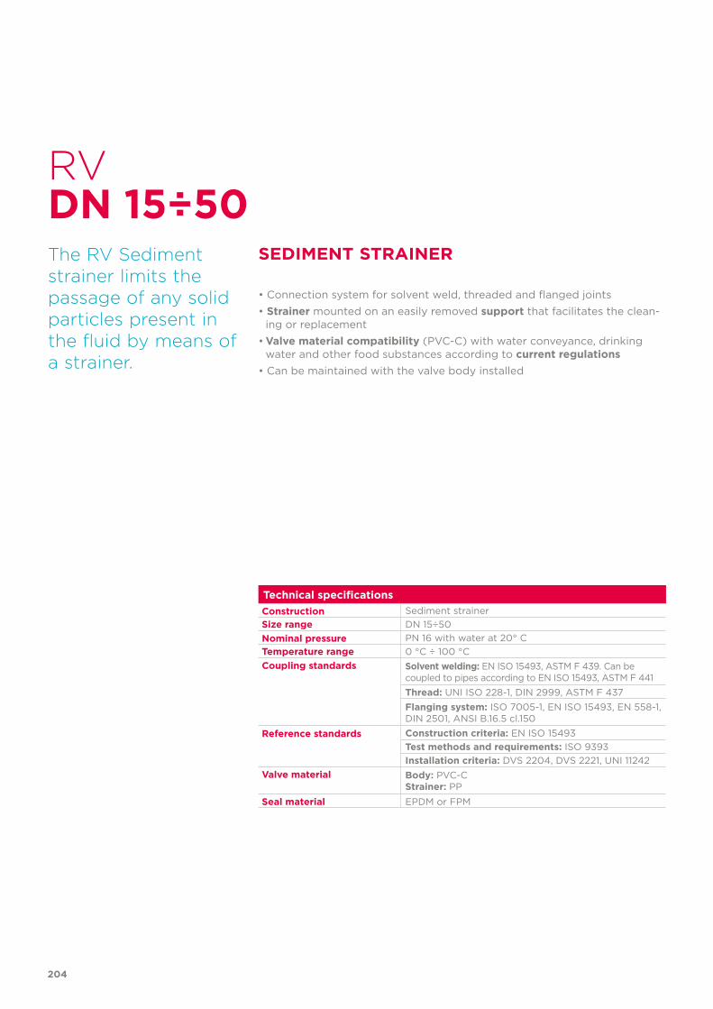
204
Technical specificationsConstruction Sediment strainerSize range DN 15÷50Nominal pressure PN 16 with water at 20° CTemperature range 0 °C ÷ 100 °CCoupling standards Solvent welding: EN ISO 15493, ASTM F 439. Can be
coupled to pipes according to EN ISO 15493, ASTM F 441Thread: UNI ISO 228-1, DIN 2999, ASTM F 437Flanging system: ISO 7005-1, EN ISO 15493, EN 558-1, DIN 2501, ANSI B.16.5 cl.150
Reference standards Construction criteria: EN ISO 15493Test methods and requirements: ISO 9393Installation criteria: DVS 2204, DVS 2221, UNI 11242
Valve material Body: PVC-CStrainer: PP
Seal material EPDM or FPM
RV
The RV Sediment strainer limits the passage of any solid particles present in the fluid by means of a strainer.
SEDIMENT STRAINER
• Connection system for solvent weld, threaded and flanged joints• Strainer mounted on an easily removed support that facilitates the clean-
ing or replacement• Valve material compatibility (PVC-C) with water conveyance, drinking
water and other food substances according to current regulations• Can be maintained with the valve body installed
DN 15÷50
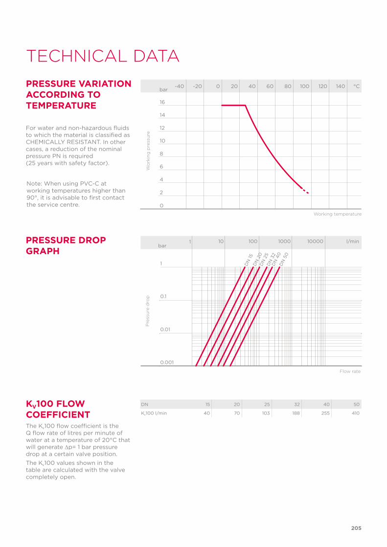
205
TECHNICAL DATA
-40 -20 0 20 40 60 80 100 120 140 °C
16
14
12
10
8
6
4
2
0
Wo
rkin
g p
ress
ure
Working temperature
barPRESSURE VARIATION ACCORDING TO TEMPERATURE
For water and non-hazardous fluids to which the material is classified as CHEMICALLY RESISTANT. In other cases, a reduction of the nominal pressure PN is required (25 years with safety factor).
PRESSURE DROP GRAPH
KV100 FLOW COEFFICIENTThe Kv100 flow coefficient is the Q flow rate of litres per minute of water at a temperature of 20°C that will generate ∆p= 1 bar pressure drop at a certain valve position.The Kv100 values shown in the table are calculated with the valve completely open.
DN 15 20 25 32 40 50
Kv100 l/min 40 70 103 188 255 410
Pre
ssu
re d
rop
Flow rate
bar1 10 100 1000 10000 l/min
1
0.1
0.01
0.001
DN
15D
N 2
0D
N 2
5D
N 3
2D
N 4
0D
N 5
0
Note: When using PVC-C at working temperatures higher than 90°, it is advisable to first contact the service centre.
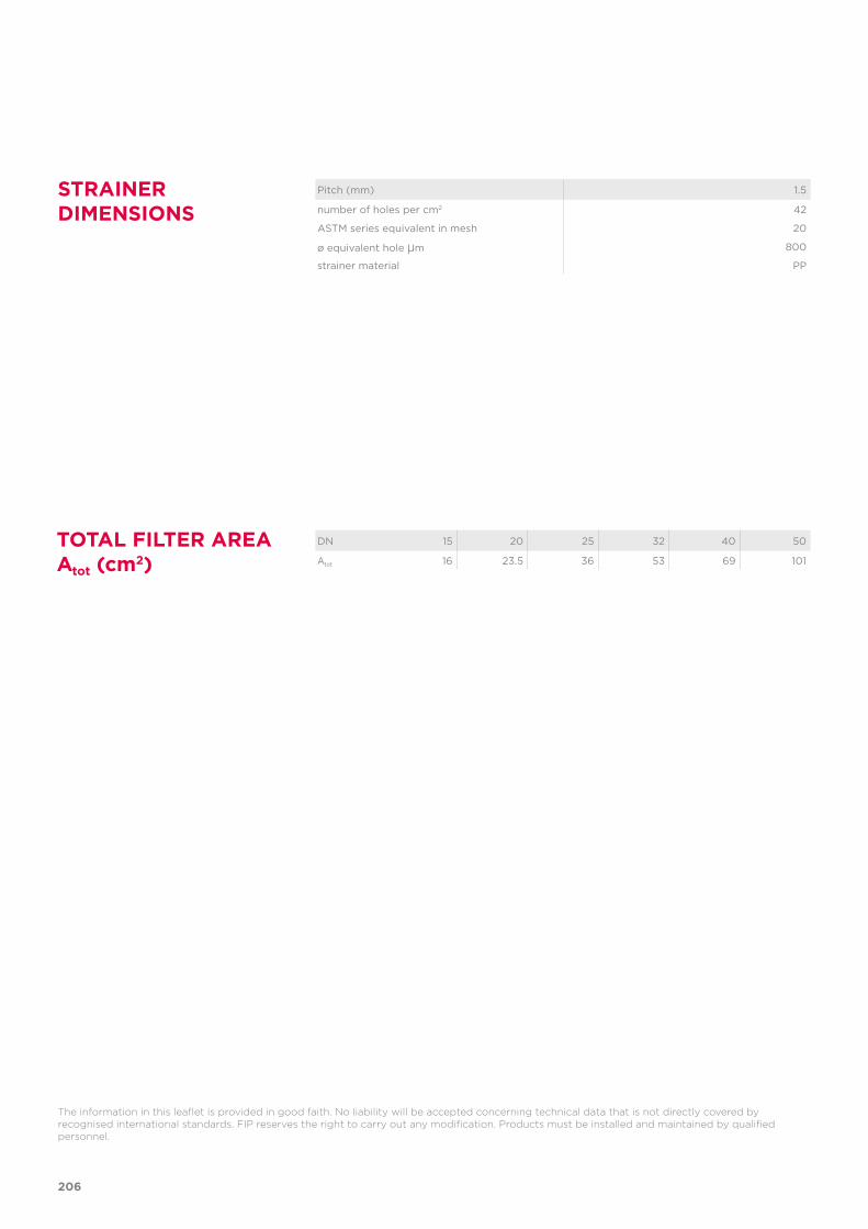
206
The information in this leaflet is provided in good faith. No liability will be accepted concerning technical data that is not directly covered by recognised international standards. FIP reserves the right to carry out any modification. Products must be installed and maintained by qualified personnel.
Pitch (mm) 1.5
number of holes per cm2 42
ASTM series equivalent in mesh 20
ø equivalent hole µm 800
strainer material PP
DN 15 20 25 32 40 50
Atot 16 23.5 36 53 69 101
TOTAL FILTER AREA Atot (cm2)
STRAINER DIMENSIONS
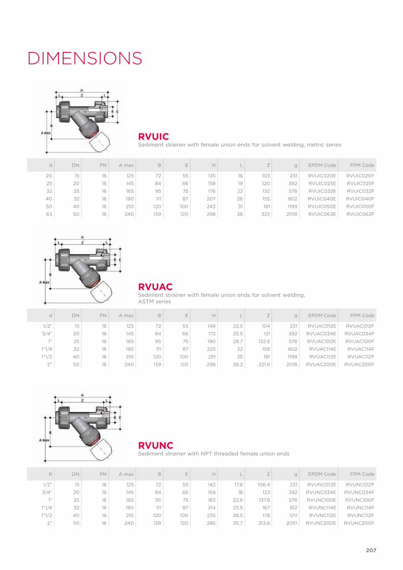
R DN PN A max B E H L Z g EPDM Code FPM Code
1/2” 15 16 125 72 55 142 17.8 106.4 231 RVUNC012E RVUNC012F
3/4” 20 16 145 84 66 159 18 123 392 RVUNC034E RVUNC034F
1” 25 16 165 95 75 183 22.6 137.8 576 RVUNC100E RVUNC100F
1”1/4 32 16 190 111 87 214 23.5 167 812 RVUNC114E RVUNC114F
1”1/2 40 16 210 120 100 235 28.5 178 1211 RVUNC112E RVUNC112F
2” 50 16 240 139 120 285 35.7 213.6 2051 RVUNC200E RVUNC200F
RVUNCSediment strainer with NPT threaded female union ends
d DN PN A max B E H L Z g EPDM Code FPM Code
20 15 16 125 72 55 135 16 103 231 RVUIC020E RVUIC020F
25 20 16 145 84 66 158 19 120 392 RVUIC025E RVUIC025F
32 25 16 165 95 75 176 22 132 576 RVUIC032E RVUIC032F
40 32 16 190 111 87 207 26 155 802 RVUIC040E RVUIC040F
50 40 16 210 120 100 243 31 181 1199 RVUIC050E RVUIC050F
63 50 16 240 139 120 298 38 222 2018 RVUIC063E RVUIC063F
d DN PN A max B E H L Z g EPDM Code FPM Code
1/2” 15 16 125 72 55 149 22.5 104 231 RVUAC012E RVUAC012F
3/4” 20 16 145 84 66 172 25.5 121 392 RVUAC034E RVUAC034F
1” 25 16 165 95 75 190 28.7 132.6 576 RVUAC100E RVUAC100F
1”1/4 32 16 190 111 87 223 32 159 802 RVUAC114E RVUAC114F
1”1/2 40 16 210 120 100 251 35 181 1199 RVUAC112E RVUAC112F
2” 50 16 240 139 120 298 38.2 221.6 2018 RVUAC200E RVUAC200F
RVUIC
RVUAC
Sediment strainer with female union ends for solvent welding, metric series
Sediment strainer with female union ends for solvent welding, ASTM series
DIMENSIONS
207
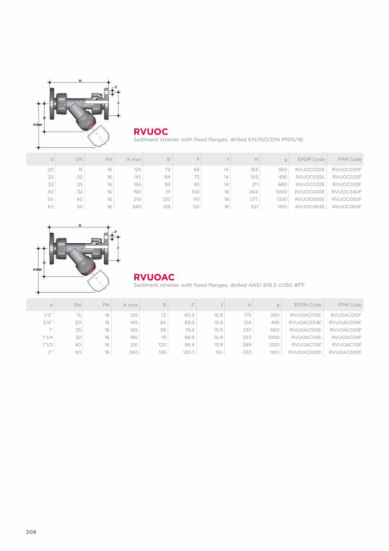
d DN PN A max B F f H g EPDM Code FPM Code
1/2” 15 16 125 72 60.3 15.9 175 360 RVUOAC012E RVUOAC012F
3/4” 20 16 145 84 69.9 15.9 214 495 RVUOAC034E RVUOAC034F
1” 25 16 165 95 79.4 15.9 237 660 RVUOAC100E RVUOAC100F
1”1/4 32 16 190 111 88.9 15.9 253 1000 RVUOAC114E RVUOAC114F
1”1/2 40 16 210 120 98.4 15.9 289 1320 RVUOAC112E RVUOAC112F
2” 50 16 240 139 120.7 19.1 333 1910 RVUOAC200E RVUOAC200F
d DN PN A max B F f H g EPDM Code FPM Code
20 15 16 125 72 65 14 163 360 RVUOC020E RVUOC020F
25 20 16 145 84 75 14 193 495 RVUOC025E RVUOC025F
32 25 16 165 95 85 14 211 660 RVUOC032E RVUOC032F
40 32 16 190 111 100 18 244 1000 RVUOC040E RVUOC040F
50 40 16 210 120 110 18 277 1320 RVUOC050E RVUOC050F
63 50 16 240 139 125 18 331 1910 RVUOC063E RVUOC063F
RVUOAC
RVUOC
Sediment strainer with fixed flanges, drilled ANSI B16.5 cl.150 #FF
Sediment strainer with fixed flanges, drilled EN/ISO/DIN PN10/16.
208
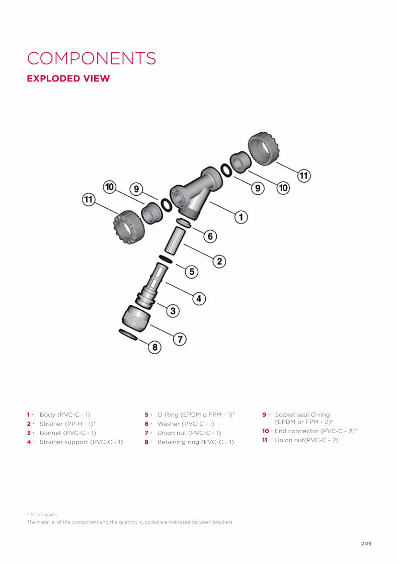
COMPONENTSEXPLODED VIEW
1 Body (PVC-C - 1)2 Strainer (PP-H - 1)*3 Bonnet (PVC-C - 1)4 Strainer support (PVC-C - 1)
* Spare parts
The material of the component and the quantity supplied are indicated between brackets
5 O-Ring (EPDM o FPM - 1)*6 Washer (PVC-C - 1)7 Union nut (PVC-C - 1)8 Retaining ring (PVC-C - 1)
9 Socket seal O-ring (EPDM or FPM - 2)*10 End connector (PVC-C - 2)*11 Union nut(PVC-C - 2)
209
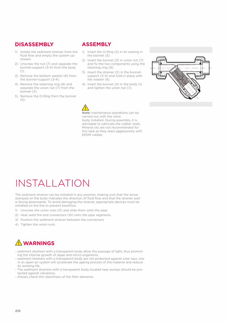
INSTALLATIONThe sediment strainer can be installed in any position, making sure that the arrow stamped on the body indicates the direction of fluid flow and that the strainer part is facing downwards. To avoid damaging the strainer, appropriate devices must be installed on the line to prevent backflow.1) Unscrew the union nuts (11) and slide them onto the pipe.2) Heat weld the end connectors (10) onto the pipe segments.3) Position the sediment strainer between the connectors4) Tighten the union nuts.
1) Insert the O-Ring (5) in its seating in the bonnet (3).
2) Insert the bonnet (3) in union nut (7) and fix the two components using the retaining ring (8).
3) Insert the strainer (2) in the bonnet-support (3-4) and hold in place with the washer (6).
4) Insert the bonnet (3) in the body (1) and tighten the union nut (7).
DISASSEMBLY ASSEMBLY1) Isolate the sediment strainer from the
fluid flow and empty the system up-stream.
2) Unscrew the nut (7) and separate the bonnet-support (3-4) from the body (1).
3) Remove the bottom washer (6) from the bonnet-support (3-4).
4) Remove the retaining ring (8) and separate the union nut (7) from the bonnet (3).
5) Remove the O-Ring from the bonnet (5).
Note: maintenance operations can be carried out with the valvebody installed. During assembly, it is advisable to lubricate the rubber seals. Mineral oils are not recommended for this task as they react aggressively withEPDM rubber.
WARNINGS- sediment strainers with a transparent body allow the passage of light, thus promot-
ing the internal growth of algae and micro-organisms.- sediment strainers with a transparent body are not protected against solar rays. Use
in an open-air system will accelerate the ageing process of the material and reduce its working life.
- The sediment strainers with a transparent body located near pumps should be pro-tected against vibrations.
- Always check the cleanliness of the filter elements.
210

211

212
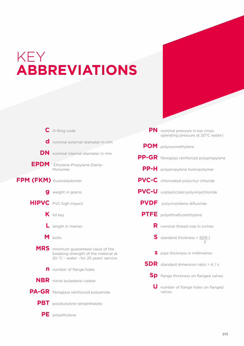
C O-Ring code
d nominal external diameter in mm
DN nominal internal diameter in mm
EPDM Ethylene-Propylene-Diene-Monomer
FPM (FKM) fluoroelastomer
g weight in grams
HIPVC PVC high impact
K lid key
L length in metres M bolts MRS minimum guaranteed value of the
breaking strength of the material at 20 °C - water - for 25 years' service
n number of flange holes
NBR nitrile butadiene rubber
PA-GR fibreglass reinforced polyamide PBT polybutylene terephthalate PE polyethylene
PN nominal pressure in bar (max. operating pressure at 20°C water)
POM polyoxymethylene
PP-GR fibreglass reinforced polypropylene
PP-H polypropylene homopolymer PVC-C chlorinated polyvinyl chloride
PVC-U unplasticized polyvinylchloride
PVDF polyvinylidene difluoride
PTFE polyethrafluorethylene
R nominal thread size in inches
S standard thickness = SDR-1 2
s pipe thickness in millimetres
SDR standard dimension ratio = d / s
Sp flange thickness on flanged valves
U number of flange holes on flanged valves
KEYABBREVIATIONS
213

Co
de
LEV
AR
AC
0
1/2
017
FIP - Formatura Iniezione Polimeri Loc. Pian di Parata, 16015 Casella Genova Italy
Tel. +39 010 9621.1
Fax +39 010 9621.209
www.fipnet.com
PIP
ES,
FIT
TIN
GS
AN
D M
AN
UA
L VA
LVE
SPV
c-c