
Dell studio battery, dell xps battery, dell vostro battery, dell inspiron battery, batterylovers.com


2
Piper Super Cub PA18
INSTRUCTION MANUAL
CONGRATULATIONS ON PURCHASING THE SUPER CUB RTF
Top Gun Park-Flite are proud to present this high performance sport scale model of the popular Super Cub.We feel that this model emulates the style, performance and character of its full size counterpart.
Supplied as a Ready to Fly package with transmitter, LiPo flight battery and charger, this model has beendesigned with the utmost care and attention to detail to produce a light weight, strong, and realistic lookingmodel aeroplane with excellent flying characteristics.
This model is a high performance miniature aircraft that allows novice to intermediate model pilots toperform both scale and aerobatic manoeuvers. The light weight, large wing area and high wing design allowthe model to fly extremely slowly, in a stable manner while still maintaining full control.
These instructions assume a reasonable level of competence for both building and flying and werecommend that the model is flown at a recognised club with frequency control measures and suitable thirdparty insurance.
The owner – pilot of this model should take note of regulations, and local bylaws before flying this aircraft.
Please take time to read through these instructions before commencing assembly. We list operations inorder of works to reduce the risk of damage during assembly.
RTF MODEL

3
WARNING
This R/C aircraft is not a toy and can result in seriousbodily harm, injury and property damage if misused.Fly only in open areas and at preferably BMFA recognisedclubs and sites.
SPECIFICATIONS
WING SPAN: 1060 MM (42”)
LENGTH: 710 MM (28”)
WING AREA: 17 DM_ (264 SQ INCHES)
WEIGHT: 540 G (19 OUNCES)
RADIO: 4 FUNCTION 35MHZ PPM
3 QTY MICRO SERVOS
25 AMP BRUSHLESS ESC
MOTOR: BRUSHLESS OUT RUNNER
9” X 5” PROPELLOR
11.1V 1250MAH LIPO BATTERY
PLEASE READTHROUGH THEWARNINGS BEFOREUSE.An 11.1V 1250 mAh lithiumpolymer (LiPo) battery rated at10C and charger is included aspart of this package and thesecells must be operated with careto prevent the risk of fire.
LiPo Batteries are soft cased andcan be easily damaged by sharpitems, puncturing of the softcasing can cause fires and werecommend that they are storedand handled carefully.
Use only a LiPo rated charger, setto a maximum of 3 cells (11.1v)and 1 amp charge current.
Remove battery from the aircraftand charge on a non flammable,non conductive surface
Due to continual and ongoingproduct development the partsshown in the manual may differfrom those supplied.

4
1. Wing with ailerons connected to factoryinstalled servos
2. Fuselage with motor, Electronic Speed Control(ESC) receiver, two quantity servo, and pushrods.
3. Fin and rudder assembly
4. Horizontal stabiliser (Tail plane) with elevator
5. Main undercarriage assembly mounting plateand wheels
6. 4 function fully proportional 35Mhz transmitter
7. Control horns and back plates for elevator andrudder
8. Tube of adhesive
9. LiPo Battery 3cell 11.1V 1250 mAh (10c)
10. LiPo charger and 12v power lead
11. Propellor – 2 off 9” diameter x 5” pitch withspinner
12. Self adhesive decal sheet.
SECTION 1: KIT CONTENTS AND DESCRIPTION

5
FUSELAGE ASSEMBLY.
Supplied complete and ready foruse. Brushless motor installedand connected to ElectronicSpeed Control (ESC), 35mhzreceiver, rudder, elevator servosconnected to push rods
WING ASSEMBLY.Supplied complete and ready tofit with hinged wing struts,aileron servo, push rods bellcranks and control hornsinstalled.
VERTICAL AND HORIZONTALSTABILISERSVertical Stabiliser (Fin andrudder) with moulded in hinges.Horizontal Stabiliser (tail planeand elevator) with moulded inhinges.
UNDERCARRIAGEASSEMBLY,Ready for use, with mountingplate and wheels.Tail wheel is pre fitted to fin.
6
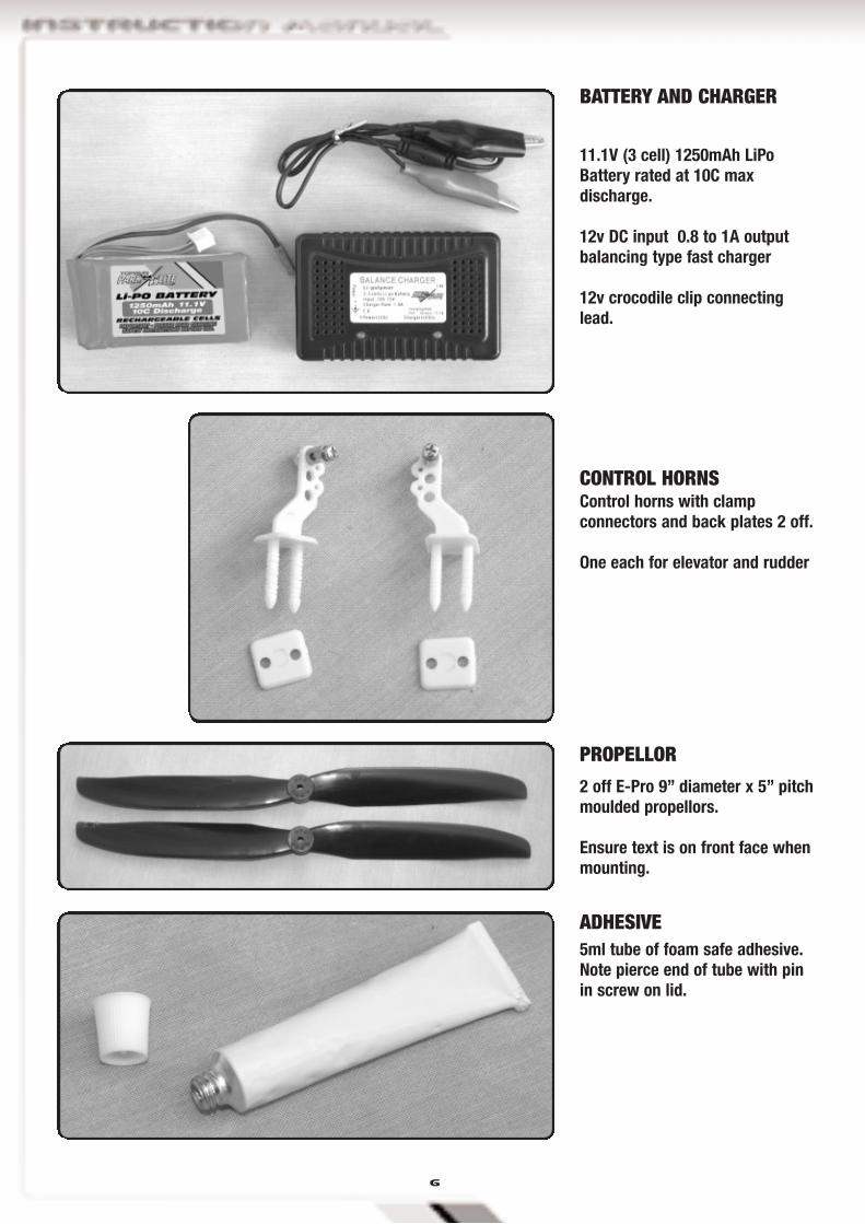
BATTERY AND CHARGER
11.1V (3 cell) 1250mAh LiPoBattery rated at 10C maxdischarge.
12v DC input 0.8 to 1A outputbalancing type fast charger
12v crocodile clip connectinglead.
CONTROL HORNSControl horns with clampconnectors and back plates 2 off.
One each for elevator and rudder
PROPELLOR
2 off E-Pro 9” diameter x 5” pitchmoulded propellors.
Ensure text is on front face whenmounting.
ADHESIVE5ml tube of foam safe adhesive.Note pierce end of tube with pinin screw on lid.

7
SECTION 2: BATTERY AND CHARGER WARNING!
A lithium polymer (LiPo) battery rated at 10Cand charger is included as part of this packageand these cells must be operated with care toprevent the risk of fire.
LiPo Batteries are soft cased and can be easilydamaged by sharp items, puncturing of the softcasing can cause fires and we recommend thatthey are stored and handled carefully.
Use only a LiPo rated charger, set to amaximum of 3 cells (11.1v) and 1 amp chargecurrent.
Remove battery from the aircraft and charge ona non flammable, non conductive surface.
BATTERY AND CHARGER
The Skylane includes a high performance 11.1V (3cell) 1250mAh LiPo Battery rated at 10C maxdischarge.
This must be charged using the dedicated 12v DCinput 0.8 to 1A output fast charger and connectinglead
Connect the crocodile lead connectors to a 12V DCpower source (a 12V car battery is ideal), ensuringthat correct polarity is observed. Red is positive (+)and Black is Negative (-).
Connect the lead into the battery charger. The powerlight will illuminate and all three LED,s will flash asa system check.
Push the white balance plug of the battery into the11.1v charger output socket to commence charging.
The Indicator light changes from amber to greenwhen the charge is complete
A full charge will take between 1 and 2 hours.
8
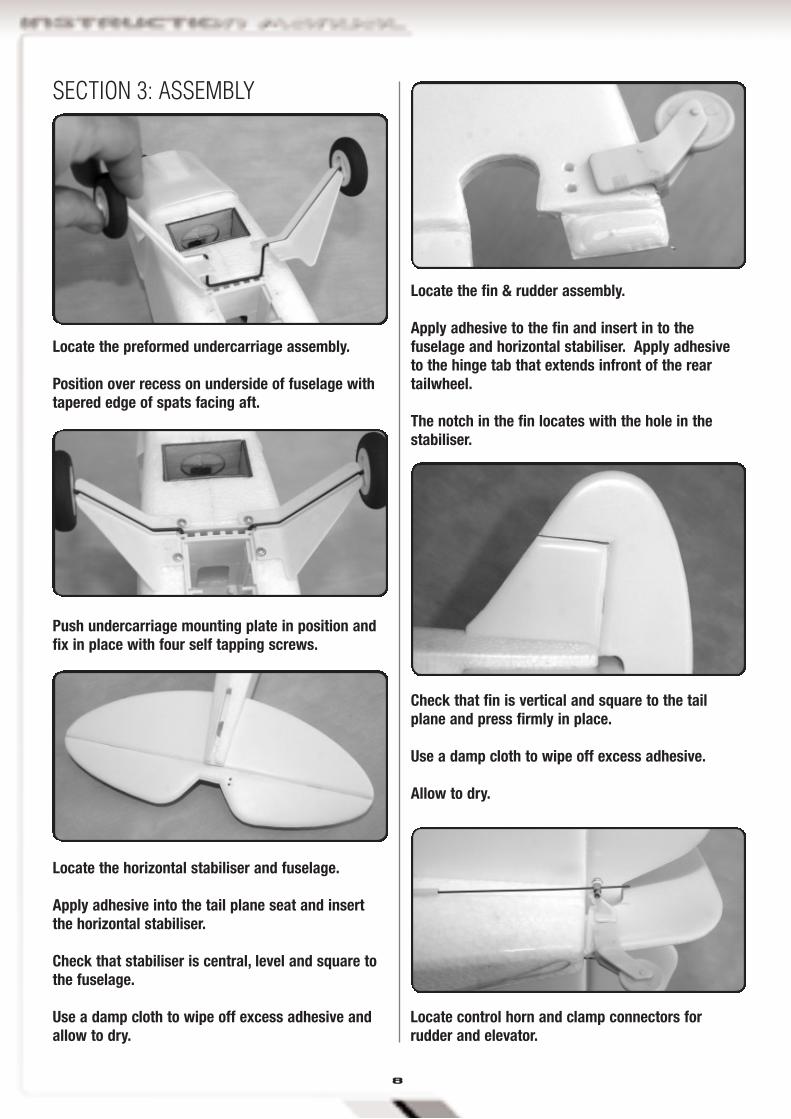
Locate the horizontal stabiliser and fuselage.
Apply adhesive into the tail plane seat and insertthe horizontal stabiliser.
Check that stabiliser is central, level and square tothe fuselage.
Use a damp cloth to wipe off excess adhesive andallow to dry.
SECTION 3: ASSEMBLY
Locate the preformed undercarriage assembly.
Position over recess on underside of fuselage withtapered edge of spats facing aft.
Push undercarriage mounting plate in position andfix in place with four self tapping screws.
Locate the fin & rudder assembly.
Apply adhesive to the fin and insert in to thefuselage and horizontal stabiliser. Apply adhesiveto the hinge tab that extends infront of the reartailwheel.
The notch in the fin locates with the hole in thestabiliser.
Check that fin is vertical and square to the tailplane and press firmly in place.
Use a damp cloth to wipe off excess adhesive.
Allow to dry.
Locate control horn and clamp connectors forrudder and elevator.

9
Slide pushrod wires through clamp connectors.
Push control horn pins through holes in controlsurface.Apply a spot of adhesive to the control horn and itsbackplate before pushing tight to surface and fittingbackplate.
Apply a spot of adhesive to the clamp connectorfixing nut to ensure it does not come loose.
Use a damp cloth to wipe off excess adhesive andallow to dry.
The Suplex 4 is a fully proportional 4 function35Mhz transmitter
The transmitter is supplied in a Mode 2configuration.
Mode 2 is also known as Throttle Left.
The left stick controls Throttle and ruddermovement.
The right stick controls aileron and elevatormovement.
Battery state is indicated by a bank of colouredLED’s. With green for full and red for empty.
As soon as the indicator changes to amber themodel should be landed to allow batteryreplacement.
A red LED indicates dangerously low voltage. Themodel should be landed immediately to replacebatteries before all control is lost.Construction of the Piper PA-18 is now complete
and the following steps can be considered as partof the daily assembly and rigging of the model.
Fix propellor to prop shaft using the M3 aluminiumspinner nut.
Note that washers are fitted to both sides of thepropellor.
The text on the propellor faces forward.
Push the spinner firmly in place.
SECTION 4: TRANSMITTER
10
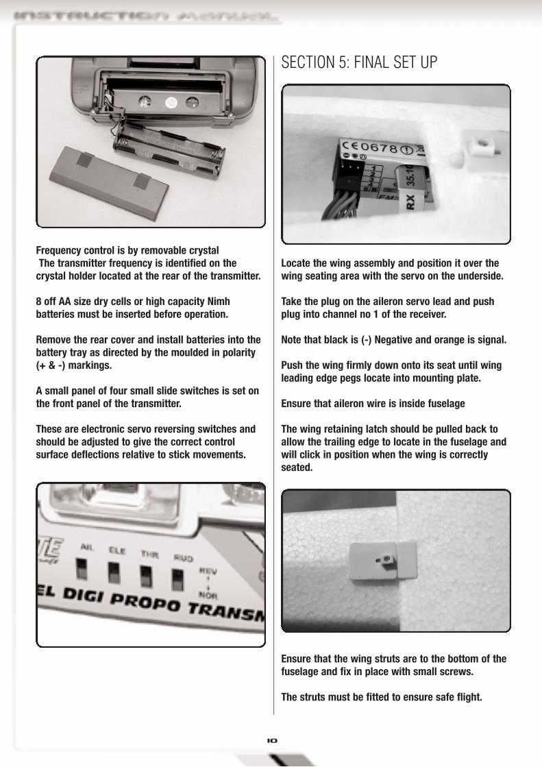
Frequency control is by removable crystalThe transmitter frequency is identified on the
crystal holder located at the rear of the transmitter.
8 off AA size dry cells or high capacity Nimhbatteries must be inserted before operation.
Remove the rear cover and install batteries into thebattery tray as directed by the moulded in polarity(+ & -) markings.
A small panel of four small slide switches is set onthe front panel of the transmitter.
These are electronic servo reversing switches andshould be adjusted to give the correct controlsurface deflections relative to stick movements.
SECTION 5: FINAL SET UP
Locate the wing assembly and position it over thewing seating area with the servo on the underside.
Take the plug on the aileron servo lead and pushplug into channel no 1 of the receiver.
Note that black is (-) Negative and orange is signal.
Push the wing firmly down onto its seat until wingleading edge pegs locate into mounting plate.
Ensure that aileron wire is inside fuselage
The wing retaining latch should be pulled back toallow the trailing edge to locate in the fuselage andwill click in position when the wing is correctlyseated.
Ensure that the wing struts are to the bottom of thefuselage and fix in place with small screws.
The struts must be fitted to ensure safe flight.
11
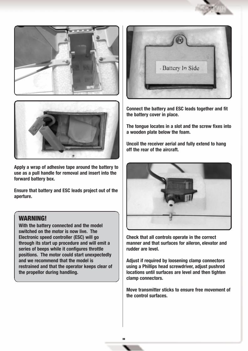
Apply a wrap of adhesive tape around the battery touse as a pull handle for removal and insert into theforward battery box.
Ensure that battery and ESC leads project out of theaperture.
Connect the battery and ESC leads together and fitthe battery cover in place.
The tongue locates in a slot and the screw fixes intoa wooden plate below the foam.
Uncoil the receiver aerial and fully extend to hangoff the rear of the aircraft.
WARNING!With the battery connected and the modelswitched on the motor is now live. TheElectronic speed controller (ESC) will gothrough its start up procedure and will emit aseries of beeps while it configures throttlepositions. The motor could start unexpectedlyand we recommend that the model isrestrained and that the operator keeps clear ofthe propellor during handling.
Check that all controls operate in the correctmanner and that surfaces for aileron, elevator andrudder are level.
Adjust if required by loosening clamp connectorsusing a Phillips head screwdriver, adjust pushrodlocations until surfaces are level and then tightenclamp connectors.
Move transmitter sticks to ensure free movement ofthe control surfaces.
12
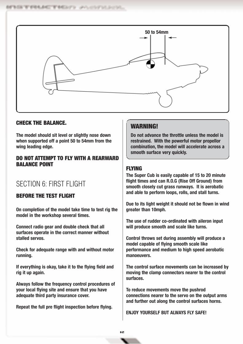
CHECK THE BALANCE.
The model should sit level or slightly nose downwhen supported off a point 50 to 54mm from thewing leading edge.
DO NOT ATTEMPT TO FLY WITH A REARWARDBALANCE POINT
FLYINGThe Super Cub is easily capable of 15 to 20 minuteflight times and can R.O.G (Rise Off Ground) fromsmooth closely cut grass runways. It is aerobaticand able to perform loops, rolls, and stall turns.
Due to its light weight it should not be flown in windgreater than 10mph.
The use of rudder co-ordinated with aileron inputwill produce smooth and scale like turns.
Control throws set during assembly will produce amodel capable of flying smooth scale likeperformance and medium to high speed aerobaticmanoeuvers.
The control surface movements can be increased bymoving the clamp connectors nearer to the controlsurfaces.
To reduce movements move the pushrodconnections nearer to the servo on the output armsand further out along the control surfaces horns.
ENJOY YOURSELF BUT ALWAYS FLY SAFE!
BEFORE THE TEST FLIGHT
On completion of the model take time to test rig themodel in the workshop several times.
Connect radio gear and double check that allsurfaces operate in the correct manner withoutstalled servos.
Check for adequate range with and without motorrunning.
If everything is okay, take it to the flying field andrig it up again.
Always follow the frequency control procedures ofyour local flying site and ensure that you haveadequate third party insurance cover.
Repeat the full pre flight inspection before flying.
50 to 54mm
SECTION 6: FIRST FLIGHT
WARNING!Do not advance the throttle unless the model isrestrained. With the powerful motor propellorcombination, the model will accelerate across asmooth surface very quickly.

13
NOTES:

14

15
When I run the program it doesn’t work or Iget no mouse cursor. I get a blank or funnyscreen or am experiencing graphicalglitches.
Update your graphics drivers from yourmanufacturers website. If you have a GeForcecard go to;http://www.nvidia.comor if you have an ATIcard go to www.ati.comIf you have a different one then you will need tofind your manufacturers website.Make sure you install the driver properly.You must click ‘Continue Anyway’ when or ifWindows throws you a warning. This isnormal.
You may also need to update your motherboarddrivers from your chipset manufacturer. e.g.VIA at www.viaarena.com, Intel, etc. You willneedto find out who the manufacturer of yourmotherboard is. Ask your computermanufacturer or right click on ‘My Computer’ ->‘Properties’ -> ‘Hardware’ tab -> ‘Device Manager’ -> ‘System Devices’. Themanufacturer should be labelled as the AGPor PCI make.
When I use my controller it moveserratically.
Recalibrate the controller. Go to the controllermenu and select your controller.Then click Re-calibrate. Follow the instructionsas they appear. For more information on settingup your controller check out the relevantsection in the manual.
The controls move in the wrong direction.
Go to the controller menu and click on thetoggle switch to reverse the channel on the axisconcerned. For more information on setting upyour controller check out the relevant section inthe manual.
Do I have to put the CD in every time I runthe program?
Yes. It is very common practice forentertainment/multimedia software.The alternative is to force people to buy highcost hardware (i.e. USB controller/interface)with the software.
FAQ’S

TGP0125 FuselageTGP0126 Main WingTGP0127 CowlTGP0128 Landing GearTGP0129 ElevatorTGP0130 RudderTGP0131 Wing StrutsTGP0132 PropellersTGP0133 Super Cub EP Decal
TGP0531 Bell Outrunner Brushless motor TGE0051 Top Gun E-Tronix Brushless 25 amp
TGP0600 Control HornsTGP0601 Quick Link Colla
TGE1000 Top Gun Etronix 8.4g servo TGP0510 Suplex 4 4ch transmitter TGP0516 Top Gun Park-Flite Lipo 12v Charger TGP0517 Adapter for li-po charger TGP0522 Lipo 11.1v 1250mAh 10c Cells
DISTRIBUTORS OF QUALITY MODEL & HOBBY PRODUCTS
Saxon House, Saxon Business Park, Hanbury Road, Bromsgrove, Worcestershire. B60 4AD. EnglandTel: +44 (0) 1527 575349 Fax: + 44 (0) 1527 570536
E-mail: [email protected] site: www.cmldistribution.co.uk
TOP GUN PARK FLITE PIPER PA-18 SUPER CUB SPARE PARTS LIST