
Pipe Valves & Fittings
82
BLOCK 16 DEVELOPMENT PROJECT AMAZON BASIN SPECIFICATION No. PP-1.0.0 SPECIFICATION FOR PIPES, VALVES & FITTINGS Page 1 of 82 TABLE OF CONTENTS SECTION PAGE 1.0 SCOPE 3 2.0 CODE COMPLIANCE 3 3.0 GENERAL REQUIREMENTS 4 4.0 MATERIALS 11 5.0 PIPE WALL THICKNESS AND CORROSION ALLOWANCE 12 6.0 PIPING SUPPORTS 13 7.0 BOLTING 14 8.0 GASKETING 14 REV. No. REVIEWED APPROVED DATE DESCRIPTION 01 Original Issue
description
Informacion valves and fittings
Transcript of Pipe Valves & Fittings

BLOCK 16 DEVELOPMENT PROJECT
AMAZON BASIN
SPECIFICATION No.
PP-1.0.0 SPECIFICATION FOR PIPES, VALVES &
FITTINGS
Page 1 of 82
TABLE OF CONTENTS
SECTION PAGE
1.0 SCOPE 3
2.0 CODE COMPLIANCE 3
3.0 GENERAL REQUIREMENTS 4
4.0 MATERIALS 11
5.0 PIPE WALL THICKNESS AND CORROSION ALLOWANCE 12
6.0 PIPING SUPPORTS 13
7.0 BOLTING 14
8.0 GASKETING 14
REV. No. REVIEWED
APPROVED DATE DESCRIPTION
01 Original Issue

BLOCK 16 DEVELOPMENT PROJECT
AMAZON BASIN
SPECIFICATION No.
PP-1.0.0 SPECIFICATION FOR PIPES, VALVES &
FITTINGS
Page 2 of 82
TABLE OF CONTENTS 8.0 GASKETING 15 CLASS A - 150# Hydrocarbons, Water, Flare 16 CLASS AD - 150# Diesel 25 CLASS AL - 150# Lube Oil, Chemical Services 31 CLASS B - 300# Flowline Laterals 36 CLASS BD - 300# Diesel 43 CLASS C - 600# Hydrocarbons, Water, Flowlines 49 CLASS CD - 600# Diesel 55 CLASS D - 900# Diesel, Flowlines 61 CLASS E - Injection Water 67 CLASS G - 150# Utility Systems 72 CLASS H - 300# Heating Oil 78 CLASS K - 600# Lube Oil, Chemical Injection for Class C and Below 83 CLASS KH -1500# Chemical Injection for Class D and Class L (Tubing) 86 CLASS L -1500# Flowlines (Spool Piece Between Choke Valves) 88 CLASS M - Hydraulic Oil (Between Hydraulic Start-ups and Turbine Generatior 90 CLASS N - Hydraulic Oil (Between Hydraulic Start-ups and Turbines 91 ATTACHMENTS Branch Connection Charts - FIGURES 01A through 01H Instrument Drain and Vent Connections - FIGURE 02A Temperature Indicator Installation - FIGURE 02B Valve Description Code - TABLE 3
BLOCK 16 DEVELOPMENT PROJECT
AMAZON BASIN
SPECIFICATION No.
PP-1.0.0 SPECIFICATION FOR PIPES, VALVES &
FITTINGS
Page 3 of 82
1.0 SCOPE 1.1 This specification defines the minimum requirements for design of piping systems and
supply of pipe, valves and fittings for onshore oil and gas production facilities operated by Repsol-YPF.
1.2 Within this specification the following definitions shall apply: COMPANY: Repsol-YPF or a designated Engineer/Contractor performing work
on behalf of Repsol-YPF. CONTRACTOR: The Contractor, Vendor or Manufacturer selected by COMPANY
to perform the work or provide equipment and services as described in this specification.
INSPECTOR: The individual(s) designated by COMPANY to act on
COMPANY'S behalf for all matters relating to Quality Control, Testing, and Acceptance of the work.
1.3 This specification shall apply to all surface production facilities piping downstream of the
wellhead, except as noted below, including: well flowlines, remote test stations, remote gathering stations, central production facilities, utilities and utility piping, skid mounted piping assemblies, interconnect piping, shop fabricated piping, field routed and field fabricated piping.
1.4 This specification is limited to "sweet" service (.05 psia H2S partial pressure or less) and
operating temperatures above -20°F. 1.5 Surface facilities such as tank farms, pumping stations, and pipeline terminals shall
follow this specification. Liquid pipelines, such as sales oil export or produced liquid which has been gas
separated shall follow this specification up to and including the last valve, battery limit or 300 feet from surface facilities, as designated by COMPANY.
1.6 Mixed phase (gas and liquid) lines outside the fenced facility area as described above,
such as individual well flowlines or combined production from a remote gathering station which has not been gas separated, shall follow ANSI B 31.4. Additional requirements which may apply to lines in this service shall be as specified by COMPANY.
2.0 CODE COMPLIANCE 2.1 All piping systems shall be designed in accordance with ANSI Piping Codes, applicable
sections of the ASME Code, Section VIII, latest editions, and this specification.
BLOCK 16 DEVELOPMENT PROJECT
AMAZON BASIN
SPECIFICATION No.
PP-1.0.0 SPECIFICATION FOR PIPES, VALVES &
FITTINGS
Page 4 of 82
2.2 The following dimensional standards shall apply for all piping drawings and materials: 2.2.1 Flanges ANSI B16.5, API 6B, API 6BX 2.2.2 Welded Fittings ANSI B16.9 and B16.11 2.2.3 Gaskets API 6BX and API 6 2.2.4 Pipe Threads ANSI B2.1 Tapered 2.2.5 Block Valves ANSI B16.10 2.2.6 Control Valves ANSI B16.10 2.2.7 Check Valves ANSI B16.10 2.2.8 High Pressure Pipe, Valves & Fittings API 6A
3.0 GENERAL REQUIREMENTS 3.1 Piping Classes The minimum standards for pipe, valves, and fittings for each service class, are
contained in the piping class sheets "A" through "K". 3.2 Drawings 3.2.1 CONTRACTOR'S piping drawings shall clearly show all piping designed by
CONTRACTOR in plan view and elevation, including all necessary partial plans, additional sections and supplementary details as necessary to fully define all piping.
3.2.2 All piping shall be fully dimensioned to define plan and elevation centerlines,
spool lengths, pipe support locations, piping clearances and pipe spacing. Compass orientation and key plan location shall be included on each piping plan where appropriate. Each section view and elevation detail shall be referenced on the appropriate plan drawing(s).
3.2.3 Piping drawings shall show each line clearly identified as to size, piping class,
fluid service, line number, flow direction and wall thickness schedule. All branch fittings, reducing fittings, non-standard fittings or piping specialty items shall be identified.

BLOCK 16 DEVELOPMENT PROJECT
AMAZON BASIN
SPECIFICATION No.
PP-1.0.0 SPECIFICATION FOR PIPES, VALVES &
FITTINGS
Page 5 of 82
3.2.4 Mechanical flowsheet drawings shall include each line, valve and piping specialty item identification in full, exactly as shown on the piping drawings. Each and every line size, change of line size, piping branch, valve and instrument connection shall be shown on the mechanical flowsheet drawings, with the exception of piping high/low point vents and drains which need not appear on the flowsheets.
3.2.5 Unless otherwise specifically authorized by COMPANY, the materials specified in
the indicated piping class table in these Standard Specifications shall be strictly adhered to in the design, requisitioning, purchasing and fabrication of each piping system. When the specified pipe, valves, fittings or other materials cannot be obtained, or if substitutions are necessary for other valid reasons, substitutions may be permitted with prior written approval by COMPANY. Any additional cost to acquire such substitutes, including impact to design, shall be for CONTRACTOR'S account.
3.2.6 It is the CONTRACTOR'S responsibility to ensure all piping systems are
designed per project requirements. In the event of any conflict between specifications, scope of work or drawings, or any lack of clear definition as to the applicability of any specification or standard, CONTRACTOR shall immediately seek to obtain written clarification from COMPANY. COMPANY approval of CONTRACTOR'S drawings in no case absolves CONTRACTOR for specification deviations contained therein, unless such deviations or assumptions are clearly brought to COMPANY'S attention, and written clarification received.
3.3 Pipe 3.3.1 Pipe wall thickness shall conform to Section 5.0. Piping smaller than 1 1/2"
nominal size shall be Schedule 80 minimum. Piping 2" and above shall be a minimum of standard wall. Stainless steel piping as per Class "AL" is an exception to this.
3.3.2 Piping smaller than 1/2" nominal size shall not be allowed. Line sizes 1-1/4", 2-
1/2", 3-1/2" and 5" shall not be used. Piping 2" and larger shall be butt welded or flanged except as noted in 3.3.4.
3.3.3 In areas of high vibration or pulsation, such as in the vicinity of reciprocating
machinery, all piping (including lube oil piping) shall be socket welded or flanged except as noted in 3.3.4.
3.3.4 Class "G" piping, 3" and smaller may be threaded. 3.3.5 Atmospheric vent, drain, sample and test valve connections 3/4" or less and all
instrument connections 3/4" or less may be threaded as shown in Tables 2A & 2B. Atmospheric vent, drain, sample and test valves are defined as those valves connected to lines or vessels by integral male end connections or by nipples of 3"

BLOCK 16 DEVELOPMENT PROJECT
AMAZON BASIN
SPECIFICATION No.
PP-1.0.0 SPECIFICATION FOR PIPES, VALVES &
FITTINGS
Page 6 of 82
total length or less, and which have no piping, other than instrument piping, connected to the downstream side of the valve.
3.3.6 A sufficient number of flanged connections shall be provided in socket weld
piping to permit disconnection of items such as pumps, exchangers, instruments, isolating valves, etc.
3.3.7 Piping shall be located so as not to present overhead or tripping hazards.
Minimum clear headroom for overhead piping shall be 7'0". 3.3.8 Piping systems shall be designed so that all valves and instruments can be
serviced conveniently. If possible, operating valves shall be accessible at grade or floor level. When this is impractical, ladders, platforms and removable grating sections shall be utilized for improved access. Chain mechanisms for operating valves are allowed.
3.3.9 Without exception, emergency shutdown valves are to be accessible from grade
or floor level and are to be located in clear areas. 3.3.10 All carbon steel pipe nipples 3/4" diameter and smaller for other than air and
utility water systems piping shall be a minimum of Schedule 160 seamless steel pipe. Pipe nipples for stainless steel pipe shall be Schedule 80S. All-threaded nipples shall not be used. A nipple shall be defined as any section of pipe 12" or less in length.
3.3.11 In lines designed to carry sand-laden fluids at erosive velocities, and in lines from
the wellheads to the production manifold where so designated by COMPANY, all turns shall be made with tees and butt weld bull plugs to minimize sand erosion. A purchased cast steel "flow tee" is acceptable.
3.3.12 Temporary startup cone or basket type strainers (screens) shall be provided in
suction lines to mechanical equipment, including, but not necessarily limited to pumps, compressors, and mechanical meters, and shall be located as close as possible to the inlet flanges. Such strainers shall have a minimum of 150% of line flow area with 1/8-inch diameter maximum size perforations, unless otherwise specified by COMPANY.
3.3.13 Branch connections per applicable specification and appropriate valves shall be
provided in the piping systems on both sides of temporary startup strainer locations to allow monitoring of pressure differential during startup.
3.3.14 Branch connections in threaded piping systems shall be made using straight tees
and swage reducers, or reduced outlet tees. 3.3.15 Branch connections in welded lines shall be butt weld straight tees or reducing
tees when the branch line is 2" nominal or larger and is equal to or greater than

BLOCK 16 DEVELOPMENT PROJECT
AMAZON BASIN
SPECIFICATION No.
PP-1.0.0 SPECIFICATION FOR PIPES, VALVES &
FITTINGS
Page 7 of 82
1/2 of the nominal run size. If the branch line is 2" nominal or larger, but less than 1/2 of the run size, welded branch fittings (such as weldolets) shall be used. Branch lines 1-1/2" and smaller shall be connected to runs 1-1/2" and smaller with branch connections as specified in Figures 1A through 1H.
Couplings or other weld-on type branch connection fittings shall not be located on
the weld joints. The distance between welds shall be a minimum of 1" or four times the header pipe thickness, whichever is greater.
3.3.16 3/4" and smaller F.S. threaded couplings, and other threaded branch fittings may
be used as the branch connection for the installation of atmospheric vent, drain, sample, and test valves with male end connections and for instrumentation purposes (i.e. gauge cocks, instrument valves, etc.). See Figures 01, 02A and 02B.
3.3.17 Couplings used for branch connections are to be attached by welding completely
through the total thickness of the pipe wall. 3.3.18 "Stub-in" branch connections shall not be permitted. 3.3.19 Drain connections and valves shall be provided at all low spots in lines. Also,
vent connections and valves shall be provided at all high spots where gas may be trapped. In addition, sample connections with valves shall be installed at appropriate points for sampling of process streams. Sample vent and drain valves shall be 1/2" minimum pipe size and shall be installed in accordance with Figure 02A. All hydrostatic test high point vents and low point drains shall be 3/4" ball valves.
3.3.20 Required changes in pressure ratings in piping systems shall be made at valves,
except as approved by COMPANY. A valve separating two pressure-rated systems shall carry the rating of the higher pressure system.
3.3.21 A control valve station will take the pressure rating change at the outlet of the
block valve downstream of the control valve. 3.3.22 A check valve between two pressure-rated systems shall carry the rating of the
higher pressure system. Note: a check valve shall not be considered a spec-break point.
3.3.23 Laterals for instrument air systems shall have block valves at the header. 3.3.24 Pump suction block valves and all pipe, valves, and fittings between such valves
and the pump suction shall have the same pressure rating as that of the pump discharge piping. In special applications it may be necessary to install certain elements in suction piping that do not have as high a pressure rating as the
BLOCK 16 DEVELOPMENT PROJECT
AMAZON BASIN
SPECIFICATION No.
PP-1.0.0 SPECIFICATION FOR PIPES, VALVES &
FITTINGS
Page 8 of 82
discharge piping. Such installations must be approved in writing by COMPANY'S project engineer, and a relief valve must be installed to protect the suction piping.
3.3.25 Block valves at pump suctions shall be full port. 3.3.26 Teflon tape shall be used on all threaded joints. Care shall be taken to prevent
extension of the tape into the line. 3.3.27 Insulating gaskets or inserts shall be installed when joining piping components of
dissimiliar metals to prevent galvanic corrosion and to isolate and cathodically protect underground pipe, where appropriate.
3.3.28 A test ring or body tap shall be supplied for all check valves in process
hydrocarbon service. 3.4 Valves 3.4.1 It is intended that sufficient valves be installed so that portions of the facility can
be isolated to permit repair of items or equipment without undue interruption of facility operations; e.g., without depressuring or draining major vessels.
3.4.2 CONTRACTOR should be aware that although the listed valves from different
manufacturers for each given class and service are basically intended to be interchangeable, some differences exist. Not all valve models have equivalent temperature ratings. In the case of ball valves, not all models are available in both full port and reduced port versions. In certain classes, valve face-to-face dimensions may differ between manufacturers. Valves with handwheels may vary in size and configuration of the handwheels, which could affect piping layout in congested areas and manifolds. In services where a particular valve model must be used for these or similar reasons, the drawings shall so specify.
3.4.3 In general, ball valves shall be used for on/off hydrocarbon and glycol services
from -20°F to 200°F for sizes 2" and larger. Orbit rising stem ball valves or gate valves shall generally be used for on/off hydrocarbon, glycol or steam services above 200°F. These same conditions shall apply when block valves are required to isolate control valves, liquid level controllers, high and low level shutdowns or alarms and gauge glasses. Globe valves shall generally be used for throttling services; however, the use of gate valves may be considered when large sizes are required if approved by COMPANY.
3.4.4 When purchasing valves, CONTRACTOR shall specify on the purchase order the
design pressure rating and the design temperature as shown on the piping class sheets, which is the equivalent of full class ratings.
3.4.5 Block valves and bypass valves are required for control valves in most cases and
where shown on COMPANY'S drawings. Spools shall be provided to permit
BLOCK 16 DEVELOPMENT PROJECT
AMAZON BASIN
SPECIFICATION No.
PP-1.0.0 SPECIFICATION FOR PIPES, VALVES &
FITTINGS
Page 9 of 82
removing a control valve without removing isolating block valves. A drain valve shall be provided to drain liquids trapped between isolating valves. Bypass valves around control valve stations shall generally be globe valves.
3.4.6 Block valves and bypass valves used with control valves shall be sized in
accordance with API RP-550. 3.4.7 Ball valves shall generally be trunnion mounted in larger sizes, especially in high-
pressure services, and in services where extremely low differential pressures may be encountered. As a guide, ball valves larger than 4" bore size in ANSI 150 and 300 lb. classes, larger than 2" bore size in ANSI 600 lb. class and larger than 1-1/2" bore size in ANSI 900 lb. and higher classes shall generally be trunnion mounted. Floating ball and floating type non-lubricated plug valves may, however, be considered for sizes outside this guideline if approved by COMPANY, provided that the required operating torque is acceptable for the application and that expected differential pressures will be high enough to assure an effective seal.
3.4.8 Ball valves shall generally be provided with solid 316 SS balls and stems. 3.4.9 Valves with primary resilient seals in hydrocarbon and glycol services shall
preferably have secondary metal-to-metal seals. 3.4.10 Unless otherwise indicated, ball valves shall be provided with manual gear
operators in lieu of lever or handwheels as follows: Pressure Rating Valve Bore ANSI 150 lb., 300 lb. 8" and larger ANSI 600 lb. 6" and larger ANSI 900 lb. 4" and larger Gate valves shall be provided with manual gear operators as follows: Pressure Rating Valve Bore ANSI 150 lb., 300 lb. 12" and up ANSI 600 lb., 900 lb. 8" and up 3.4.11 Full opening ball or gate valves shall be used on the suction side of all centrifugal
pumps, on both the suction and discharge side of all reciprocating pumps, on the upstream side of all liquid meters and when minimum pressure drop requirements or other conditions dictate (sphere launching, meter proving, etc.). Full opening valves shall be identified on the drawings with the notation (F.B.) following the valve identification. Valves used on both the inlet or outlet side of relief valves shall be full opening.

BLOCK 16 DEVELOPMENT PROJECT
AMAZON BASIN
SPECIFICATION No.
PP-1.0.0 SPECIFICATION FOR PIPES, VALVES &
FITTINGS
Page 10 of 82
All pipeline valves shall be full open thru-conduit type up to the launcher, receiver
or pipeline terminal in order to allow for passage of pipeline spheres, inspection devices, etc.
3.4.12 Conventional low pressure butterfly valves may be used in water services only,
provided pressures cannot exceed 150 psig. 3.4.13 Lever operated butterfly valves shall have positive detent or lever lock handles. 3.4.14 Power operators shall be provided on all emergency shutdown valves and on
centrifugal compressor inlet and discharge valves, or where noted in the project scope of work.
3.4.15 Gate valves 2" and larger in services above 200°F shall be expanding gate, one-
piece slab-gate, or flexible disc type. Gate valves with power operators shall be one-piece slab-gate or flexible disc type regardless of operating temperatures.
3.4.16 Gate or ball valves, used for atmospheric vent, drain, sample and test services
shall generally be 1/2" threaded type construction, or 3/4" for hydrotest service. 3.4.17 Valves with exposed threaded rising stems, OS&Y type, shall not be used unless
authorized by COMPANY. 3.4.18 Open-ended valves shall be equipped with removable steel plugs, blind flanges,
or nipples with screwed caps. Open-ended socket weld valves shall be threaded at the open end and provided with a removable plug, or shall have an integral forged or welded nipple threaded and capped at the exposed end. When used to close open-ended valves, blind flanges shall be drilled and tapped and equipped with a 1/2" needle valve.
3.4.19 Check valves 2" and larger shall be full bodied, horizontal swing type, except for
reciprocating compressor discharge service where piston-controlled check valves will be used. All check valves 2" and larger shall be furnished with bolted bonnets, and bonnets shall have a 1/2" NPT tap with plug. Clapper stops shall not be attached by means of this bonnet tap.
3.4.20 Check valves smaller than 2" shall be full bodied ball, lift plug or swing type and
shall be serviceable through the bonnet opening. When available, bolted bonnets are preferred.
3.4.21 Swing check valves in hydrocarbon service below 300°F shall be provided with a
primary resilient seal and a secondary metal-to-metal seal. Resilient seals shall be located in the valve body, and the body seat shall be removable. Removable seats and resilient seals shall be serviceable through the bonnet opening.

BLOCK 16 DEVELOPMENT PROJECT
AMAZON BASIN
SPECIFICATION No.
PP-1.0.0 SPECIFICATION FOR PIPES, VALVES &
FITTINGS
Page 11 of 82
3.4.22 All valves in services above 300°F shall have metal-to-metal seats and ring joint or spiral wound 304 SS (Flexitallic type) bonnet gasket.
3.4.23 Every block valve shall be provided with a lever, handle, or handwheel as
necessary to operate the valve. 3.5 Fittings 3.5.1 In general, flanges 900 lb. ANSI and above shall be RTJ. Flanges 600 lb. ANSI
and lower shall be RF, with a serrated spiral finish of 125.500 AARH per ANSI B16.5.
3.5.2 Weld neck flanges are required for all flanged piping for sizes 2" and larger. 3.5.3 Reducing or expanding flanges shall be not used without prior client approval. 3.5.4 Steel flanges used to mate with equipment having cast or ductile flat face flanges
shall have the faces machined flat. The surface finish shall meet the requirements of ANSI B16.5.
3.5.5 API flanges rated at 2000, 3000 or 5000 psi shall be API Type 6B. 3.5.6 All 90° weld ells shall be long radius, unless restricted by available space. If short
radius weld ells are used, they shall be derated to 80% of the calculated allowable working pressure if subject to pulsations. In flowlines (Class "C"), no 90° ells shall be used. Flow tees or target tees shall be used for 90° turns.
3.5.7 Threaded bushings shall not be used in pressure piping systems. 3.5.8 Eccentric reducers installed with the straight side up shall be used when line size
reductions are required for pump suction connections. 3.5.9 Unions in hydrocarbon service shall be integral ground joint steel to steel seats. 3.5.10 All threaded pipe plugs shall be forged steel bull or hex head. Square head pipe
plugs shall not be used.
4.0 MATERIALS 4.1 The materials used for pipe, valves and fittings shall be in accordance with the attached
tables and specifications. One copy of the material test reports for all pipe, valves and fittings shall be shipped with the components and a second copy shipped with the invoice.
4.2 All pipe, valves and fittings shall be new and unused.
BLOCK 16 DEVELOPMENT PROJECT
AMAZON BASIN
SPECIFICATION No.
PP-1.0.0 SPECIFICATION FOR PIPES, VALVES &
FITTINGS
Page 12 of 82
4.3 All pipe and fittings shall have legible mill coding as to ASTM type and grade of material, and mill heat numbers traceable to mill test reports.
4.4 No valves or fittings of brass, aluminum, cast iron, malleable iron, steel-iron or semi-steel
shall be used in hydrocarbon service. All valves shall be furnished with non-asbestos packing and gaskets.
4.5 All piping shall be ASTM A-106 Grade B seamless, except for the lube oil system, which
is stainless steel pipe. In cases where ASTM A-106 Grade B is not available, ASTM A-53 Grade B seamless or API 5L Grade B seamless may be substituted subject to COMPANY's written approval provided at least one of the following conditions applies:
a. In all services, provided the mill analysis data show the manganese to carbon
ratio to be above 4 to 1. All such pipe must be traceable back to the mill. All documentation must be checked by COMPANY before any pipe is used.
b. In all services, provided that specimens taken from each heat to be used meet
the Charpy "V" Notch minimum energy absorption requirement of 15 ft-lbs. at 40°F. Tests to be conducted as described in ASTM A-370.
c. In non-pressured (gravity drain) service and non-critical (fresh water, utility water,
instrument air, and atmospheric tank vent) services, provided such lines are not located on or directly connected to skids containing reciprocating equipment (compressors, engines or pumps).
4.6 Flanges, threaded and socket weld fittings, and other similar forged steel fittings shall be
ASTM A-105. 4.7 Butt weld fittings shall be seamless carbon steel, ASTM A-234 Grade WPB, and shall
have the same nominal wall thickness throughout the elbow, as the pipe to which they attach, except that short radius ells, which have been derated as specified in paragraph 3.5.6 may require a wall thickness greater than that of the connecting pipe.
4.8 Sealant for threaded piping shall be teflon tape or use teflon paste applied beforehand. 4.9 Teflon tape shall not be used on pneumatic tubing installations.
5.0 PIPE WALL THICKNESS AND CORROSION ALLOWANCE 5.1 Pipe thickness schedules shall be per each piping class sheet. The wall thickness is
based on the formula referenced in paragraph 5.4 using ASTM A106 Grade B pipe (or substitute pipe grades provided they have the same allowable stress and construction qualified per paragraph 4.5) with a corrosion allowance of .0625". Stainless piping uses allowables for ASTM A-312 TP316L pipe.

BLOCK 16 DEVELOPMENT PROJECT
AMAZON BASIN
SPECIFICATION No.
PP-1.0.0 SPECIFICATION FOR PIPES, VALVES &
FITTINGS
Page 13 of 82
Wall thickness of piping not covered by the piping class sheets shall be calculated per paragraph 5.4 (unless otherwise required per paragraphs 5.6 or 5.7), including the following cases:
5.1.1 Pipe sizes not covered by the class sheets. 5.1.2 Piping classes not covered by the class sheets. 5.1.3 Materials other than A106 Grade B or qualified substitute. 5.1.4 Services requiring a corrosion/erosion allowance greater than .0625". 5.2 The piping class sheets in several cases specifies a pipe wall heavier than the minimum
required by paragraph 5.4. The intent is to simplify the number of required pipe schedules and to standardize on those which are readily available.
5.3 In no case shall nominal wall thickness be used less than shown in the class sheets or
without COMPANY approval. Corrosion allowance shall be considered as the sum of corrosion, erosion and mechanical allowances, and shall not be less than .0625" without COMPANY approval. For threaded pipe, the mechanical allowance is in addition to the .0625" allowance.
5.4 Wall thickness shall be qualified by Equations 2 and 3a in the ANSI B31.3 Code
Paragraphs 304.1.1 and 304.1.2, utilizing a .0625" corrosion allowance, SE = 20,000 psi and mill under-thickness tolerance of 12-1/2%.
5.5 Maximum allowable working pressure shall be derated at piping design temperatures
above 100°F in accordance with each piping class specification. 5.6 Services where vibration, cyclic pressure or significant thermal and mechanical stresses
are present shall be individually checked for code compliance and good practice may require a wall thickness other than specified in the class sheets. Piping expansion/contraction loops shall be provided as necessary to minimize thermal stresses.
5.7 For specified buried lines and other services as may be designated by COMPANY,
piping shall meet the requirements as per Specification SS-061-50-10.
6.0 PIPING SUPPORTS 6.1 Piping shall be supported as necessary to meet the requirements of the ASME B31.3
Piping Code, Pipe, in general, shall be supported utilizing the supports shown in Brown & Root Specification PP-2.0.0, or other adequate approved supporting methods.
BLOCK 16 DEVELOPMENT PROJECT
AMAZON BASIN
SPECIFICATION No.
PP-1.0.0 SPECIFICATION FOR PIPES, VALVES &
FITTINGS
Page 14 of 82
6.2 In all areas subject to excessive mechanical vibration or line pressure pulsations, including all piping on reciprocating compressor, engine, or pump skids and reciprocating pump discharge lines, piping shall be supported in a manner to minimize vibration.
6.3 Bolting for all u-bolt supports shall be provided with double nuts to prevent loosening. All
u-bolts shall be cadmium plated. 6.4 Pipe supports shall not protrude into walkways or be located in any area that would
create a personnel hazard.
7.0 BOLTING For flanged piping systems, stud bolts, threaded over their length, shall be used. All studs and
nuts shall be cadmium plated. Studs and nuts are specified in each class sheet.
8.0 GASKETING Gaskets are specified in each class sheet. SERVICE Process Hydrocarbons Produced Water Injection Water Flare Pilot and Ignitor Lines RATING 150# ANSI R.F. - Steel MAXIMUM DESIGN TEMPERATURES 300°F (Flare Line Only) Note: Valves need to meet 230°F; 150 psig MAXIMUM DESIGN PRESSURES -20°F to 100°F; 275 psig 150°F; 255 psig 230°F; 150 psig 300°F; 100 psig (Flare Li

BLOCK 16 DEVELOPMENT PROJECT
AMAZON BASIN
SPECIFICATION No.
PP-1.0.0 SPECIFICATION FOR PIPES, VALVES &
FITTINGS
Page 15 of 82
BLOCK 16 DEVELOPMENT PROJECT
AMAZON BASIN
SPECIFICATION No.
PP-1.0.0 SPECIFICATION FOR PIPES, VALVES &
FITTINGS
Page 16 of 82
nes Only) PIPE ASTM A-106 Grade B Seamless 3/4" and smaller nipples - Schedule 160 1-1/2" and smaller pipe - Schedule 80; TE 2" - 3" Schedule 80; BE 4" - 24" pipe - Standard Weight; BE API 5 L, Grade B, ERW 26" - 30" pipe - Standard Weight; BE VALVES Ball Valves
1/2" through 1-1/2" BA-411 1" through 4" BA-113 1" through 4" BA-123 (F.B.) 6" and larger BA-127 (F.B.)
1440 lb. min CWP, carbon steel body, threaded end, regular port, 316SS ball and stem, lever operated WKM, Dynaseal 310, #B-136-CS-02-S1, or equal 150# ANSI carbon steel body, 316SS ball and stem, R.F. flanged end, regular port, lever operated, floating ball WKM, Dynaseal 310, #B-100-CS-02-S1-HL, or equal 150# ANSI carbon steel body, 316SS ball and stem, R.F. flanged end, full port, floating ball, lever operated WKM Dynaseal 310, #B-110-CS-02-S1-HL, or equal 150# ANSI, carbon steel body, 316SS ball and stem, R.F. flanged end, full port, lever operated, gear operated (8" and above) and fire tested trunnion mounted, standard trim WKM Dynaseal 370 CT-21-AAF-23, (full port), or equal (6"-12") Demco Series "V" 10XXXX-1222665, or

BLOCK 16 DEVELOPMENT PROJECT
AMAZON BASIN
SPECIFICATION No.
PP-1.0.0 SPECIFICATION FOR PIPES, VALVES &
FITTINGS
Page 17 of 82
6" and larger BA-117 Check Valves 1-1/2" and smaller CK-821 2" and larger CK-123 1" and larger (Pulsating service) CK-118 2" and larger CK-125
equal (14"-24") 150# ANSI carbon steel body, 316SS ball and stem, R.F. flanged end, reduced port, lever operated, gear operated (8" and above) and fire tested trunnion mounted, standard trim WKM Dynaseal 370 CT-21-AAF-23, (regular port), or equal (6"-12") Grove Fig. B-5, or equal (14"-24") 800#, CWP, carbon steel, screwed end, full opening swing check, resilient and removable seat. Buna-N for the clapper seal and the bonnet seal o-ring. Valve to be able to operate in horizontal or vertical (with flow up) configuration Tom Wheatley Fig. 10A, or equal 150# ANSI, carbon steel, flanged end, bolted bonnet with 1/2" NPT tap, full opening through conduit swing check, resilient and removable seat. Valve to be able to operate in horizontal or vertical (with flow up) configuration Tom Wheatley Fig. 1515, or equal 150# ANSI, carbon steel, body, R.F. flanged end, bolted bonnet, piston controlled gas service check valve Norriseal "Flo-Lift" w/standard trim 150# ANSI, carbon steel body, wafer check, (to mate with R.F. flange), stellite faced disk and seats Mission Duo Check # G155SPF, or equal

BLOCK 16 DEVELOPMENT PROJECT
AMAZON BASIN
SPECIFICATION No.
PP-1.0.0 SPECIFICATION FOR PIPES, VALVES &
FITTINGS
Page 18 of 82
2" and Larger CK-163 Butterfly Valves 3" through 24" BF-120 Gate Valves 1/2" through 1-1/2" GA-211 2" and larger GA-123 (F.B.) Globe Valves 1/2" through 1-1/2"
150# ANSI, carbon steel, flanged end, bolted bonnet with 1/2" NPT tap, full opening swing check, resilient and removable seat, with counterbalance weights. Tom Wheatley, Fig. 1515, or equal. 150# ANSI, carbon steel body, lug style body, C.S. disc with 17-4 stem, reinforced teflon seal, graphite packing, lever operated, gear operated (8" and larger). WKM Dynacentric #A5111-01-S02-13, or equal 2000# CWP, forged carbon steel, screwed end, bolted bonnet, inside screw-rising stem type, wedge gate with hard faced integral seats, handwheel operated Vogt #12161, or equal 150# ANSI, carbon steel, R.F. flanged end, full opening, handwheel operated (through 10" bore size) or gear operated (12" bore size and larger), standard trim, slab gate. Outside screw rising stem type valves to be provided with enclosed stem protector. Visual position indicator to be provided when available (bore size to be specified on COMPANY'S drawings for 12" and larger line sizes) WKM, "Saf-T-Seal", or equal
BLOCK 16 DEVELOPMENT PROJECT
AMAZON BASIN
SPECIFICATION No.
PP-1.0.0 SPECIFICATION FOR PIPES, VALVES &
FITTINGS
Page 19 of 82
GL-211 2" and larger GL-113 Needle Valves 1/2" through 3/4" NE-030 Three-Way Plug Valves 3" and larger PL-119
2000# CWP, forged carbon steel, threaded end, bolted bonnet, inside screw rising stem type, with hard faced integral seat, handwheel operated Vogt #12181, or equal 150# ANSI, carbon steel, R.F. flanged end, handwheel operated, renewable seat Crane 143X, or equal 6000# CWP, 316SS bar stock, soft seat, 1/4" orifice minimum, (3/8" minimum for 3/4" valve), male by female NPT. Specify extended body (L) for installation in check valve bonnets Anderson Greenwood, H1VDS-44QR, or equal (1/2" X 1/2") Anderson Greenwood, H1VDS-66Q, or equal (3/4" X 3/4") (For relief header and atmospheric tank vent header isolation service) 150# ANSI, carbon steel, R.F. flanged end, multiport, PTFE-sleeved plug valve, lever operated (worm gear operator 6" and up). "Transflo" or "wide port" arrangement required to prevent accidental shutoff of vent source. (COMPANY'S project engineer must specify specific MANUFACTURER, figure number and required port arrangement on COMPANY'S piping drawings.)

BLOCK 16 DEVELOPMENT PROJECT
AMAZON BASIN
SPECIFICATION No.
PP-1.0.0 SPECIFICATION FOR PIPES, VALVES &
FITTINGS
Page 20 of 82
Fittings Ells and Tees 1/2" through 1-1/2" 2" and larger Unions 1-1/2" and smaller Couplings 1/2" through 1-1/2" Plugs 1/2" through 1-1/2" 2" and larger Reducers 1/2" through 1-1/2" 2" and larger Flanges 1/2" through 1-1/2" 2" and larger
Tufline, Fig. 037/037EG, Carbon Steel Plug, PTFE-sleeve, or equal 3000# F.S., threaded, ASTM A-105 Butt weld, ASTM A-234 Grade WPB seamless, wall to match pipe 3000#, F.S., steel to steel ground joint seats, ASTM A-105 3000#, F.S. threaded, ASTM A-105 Solid forged steel bar stock, ASTM A-105, 3" long Use caps 3000# F.S., screwed, ASTM A-105 Butt weld, ASTM A-234 Grade WPB seamless, wall to match pipe 150# ANSI R.F. (serrated spiral finish), forged steel, screwed end, ASTM A-105 per ANSI B16.5
BLOCK 16 DEVELOPMENT PROJECT
AMAZON BASIN
SPECIFICATION No.
PP-1.0.0 SPECIFICATION FOR PIPES, VALVES &
FITTINGS
Page 21 of 82
Bolts and Nuts Gaskets Branch Connections
150# ANSI R.F. (serrated spiral finish), weld neck, forged steel, bored to I.D. of pipe, ASTM A-105, per ANSI B16.5. (Flanges 26" and larger shall be per MSS-SP-44) Bolts - ASTM A-193, Grade B7, cadmium plated Nuts - Heavy hexagon, ASTM A-194, Grade 2H, cadmium plated 0.175" thick spiral wound 304 stainless steel and non-asbestos, flexitallic style CG or equal with flexite filler (to be 1/8" thick after full compression), 150# rating. 1/16" Garlock HTC 9850, or equal compressed non-asbestos carbon fiber gasket with nitrile binder (For flat face flanges on valves and equipment) See paragraphs 3.3.13 through 3.3.18 See Figure 01A

BLOCK 16 DEVELOPMENT PROJECT
AMAZON BASIN
SPECIFICATION No.
PP-1.0.0 SPECIFICATION FOR PIPES, VALVES &
FITTINGS
Page 22 of 82
NOTES (1) Some valves noted in this specification may be limited to less than 200°F service temperatures
as indicated by (°F max.), or may require special seat and/or other seal materials to meet the maximum design pressure rating at temperatures above that indicated for the standard materials by (°F std.). The purchaser should always specify the design pressure rating and maximum service temperature when service temperatures may exceed 150°F.
(2) See paragraph 4.5 for conditions under which API 5L Grade B seamless or ASTM A-53 Grade B
seamless may be substituted if ASTM A-106 Grade B is not available. (3) 1-1/2" and smaller pipe will be threaded in this class. (4) Flanged end valves of equivalent size, type, and pressure rating listed in this specification are
intended to be interchangeable with respect to face to face dimensions. However, face to face dimensions of random sizes within a manufacturer's product line listed may vary from those of other manufacturers. It is, therefore, the purchaser's responsibility to check these dimensions and to modify the piping drawings prior to fabrication to compensate for any such dimensional variations for the valves purchased.
(5) Provide full opening valve port when COMPANY's valve designation is followed by the suffix
(F.B.) on either the mechanical flow sheet or the piping drawings. (6) Where short radius ells and tees are specified, piping must be derated to 80% WP in
accordance with paragraph 3.5.6. SERVICE Diesel RATING 150# ANSI R.F. - Steel MAXIMUM DESIGN TEMPERATURE 100°F MAXIMUM DESIGN PRESSURE -20°F TO 100°F; 275 psig PIPE ASTM A-106 Grade B. Seamless 3/4" and smaller nipples - Schedule 160 1" - 1-1/2" pipe - Schedule 80; PE 2" - 30" pipe - Standard Weight, BE API 5L, Grade B, ERW 26"-30" pipe - Standard Weight; BE VALVES Ball Valves

BLOCK 16 DEVELOPMENT PROJECT
AMAZON BASIN
SPECIFICATION No.
PP-1.0.0 SPECIFICATION FOR PIPES, VALVES &
FITTINGS
Page 23 of 82
1/2" through 1-1/2" BA-810 1/2" through 1-1/2" BA-812 1/2" through 1-1/2" BA-822 2" through 4" BA-113 2" through 4" BA-123 (F.B.) 6" and larger BA-127 (F.B.) 6" and larger BA-117
1000 psi CWP, carbon steel body, socketweld X threaded end, regular port, 316SS ball and stem, lever operated Watts C-7503-SS, or equal 1000 psi CWP, carbon steel body, 316SS ball and stem, socketweld end, regular port, lever operated Watts C-7501-SS, or equal 1000 psi CWP, carbon steel body, 316SS ball and stem, socketweld end, full port, lever operated. Watts C-7801-SS, or equal 150# ANSI carbon steel body, 316SS ball and stem, R.F. flanged, regular port, lever operated, floating ball WKM, Dynaseal 310, #B-100-CS-02-S1-HL, or equal 150# ANSI carbon steel body, 316SS ball and stem, R.F. flanged, full port, floating ball, lever operated WKM Dynaseal 310, #B-110-CS-02-S1-HL, or equal 150# ANSI, carbon steel body, 316SS ball and stem, R.F. flanged, full port, lever operated, gear operated (8" and above), and fire tested trunnion mounted, standard trim WKM, Dynaseal 370 CT-21-AAF-23, (full port), or equal (6"-12") Demco series "V" 10XXXX-1222665, or equal (14"-24") 150# ANSI, carbon steel body, 316SS ball and stem, R.F. flanged, reduced port, lever operated, gear operated (8" and above) and fire tested, trunnion mounted, standard trim WKM, Dynaseal 370, CT-21-AAF-23, (Regular Port), or equal (6"-12") Grove Fig. B-5, or equal (14"-24")
BLOCK 16 DEVELOPMENT PROJECT
AMAZON BASIN
SPECIFICATION No.
PP-1.0.0 SPECIFICATION FOR PIPES, VALVES &
FITTINGS
Page 24 of 82
Check Valves 1-1/2" and smaller CK-222 2" and larger CK-123 Gate Valves 1/2" through 1-1/2" GA-212 2" and larger GA-123 (F.B.) Needle Valves 1/2" through 3/4" NE-030
2000 psi, CWP, carbon steel, socketweld end, full opening swing check, resilient and removable seat. Viton-A for the clapper seal and the bonnet seal o-ring. Valve to be able to operated in horizontal or vertical (with flow up) configuration. Tom Wheatley Fig. 12A, or equal 150# ANSI, carbon steel, R.F. flanged, bolted bonnet with 1/2" NPT tap, full opening swing check, resilient and removable seat. Valve to be able to operate in horizontal or vertical (with flow up) configuration. Tom Wheatley Fig. 1515, or equal 2000# CWP, forged carbon steel, socketweld end, bolted bonnet, inside screw-rising stem type, wedge gate with hard faced integral seats, handwheel operated Vogt #SW-12161, or equal 150# ANSI, carbon steel, R.F. flanged, full opening, handwheel operated (through 10" bore size) or gear operated (12" bore size and larger), standard trim, slab gate. Outside screw-rising stem type valves to be provided with enclosed stem protector. Visual position indicator to be provided when available bore size to be specified on COMPANY'S drawings for 12" and larger line sizes). WKM, "Saf-T-Seal", or equal 6000# CWP, 316SS bar stock, soft seat, 1/4" orifice minimum, (3/8" minimum for 3/4" value), male by female npt. Specify extended body (L) for installation in check valve bonnets. Anderson Greenwood, H1VDS-44QR, or equal (1/2" x 1/2") Anderson Greenwood, H1VDS-66Q, or equal (3/4" x 3/4")

BLOCK 16 DEVELOPMENT PROJECT
AMAZON BASIN
SPECIFICATION No.
PP-1.0.0 SPECIFICATION FOR PIPES, VALVES &
FITTINGS
Page 25 of 82
Globe Valves 1/2" through 1-1/2" GL-212 2" and larger GL-113 Fittings Ells and Tees 1/2" through 1-1/2" 2" and larger Couplings 1/2" through 1-1/2" Plugs 1/2" through 1-1/2" 2" and larger Reducers 1/2" through 1-1/2" 2" and larger Unions 1/2" through 1-1/2"
2000# CWP, forged carbon steel, socketweld end, bolted bonnet, inside screw rising stem type, with hard faced integral seat, handwheel operated Vogt #SW12181, or equal 150# ANSI, carbon steel, R.F. Flanged, handwheel operated, renewable seat. Crane 143X, or equal 3000# F.S., socketweld, ASTM A-105 Buttweld, ASTM A-234 Grade WPB seamless, wall to match pipe 3000# F.S. socketweld, ASTM A-105 Solid forged steel bar stock, ASTM A-105, 3" long Use caps 3000# F.S., socketweld, ASTM A-105 Buttweld, ASTM A-234 Grade WPB seamless, wall to match pipe. 3000#, F.S., steel to steel ground joint seats, ASTM A-105
BLOCK 16 DEVELOPMENT PROJECT
AMAZON BASIN
SPECIFICATION No.
PP-1.0.0 SPECIFICATION FOR PIPES, VALVES &
FITTINGS
Page 26 of 82
Flanges 1/2" through 1-1/2" 2" and larger Bolts and Nuts Gaskets Branch Connections
150# ANSI R.F. (serrated spiral finish), forged steel, socketweld, ASTM A-105 per ANSI B16.5 150# ANSI R.F. (serrated spiral finish), weld neck, forged steel, ASTM A-105, per ANSI B16.5 Bolts - ASTM A-193, Grade B7, cadmium plated Nuts - Heavy Hexagon, ASTM A-194, Grade 2H, cadmium plated 0.175" thick spiral wound 304SS and non-asbestos, flexitallic style CG or equal, with flexite filler (to be 1/8" thick after full compression), 150# rating 1/16" Garlock HTC 9850 or equal compressed non-astestos carbon fiber gasket with nitrile binder (For flat face flanges on valves and equipment) See paragraphs 3.3.13 through 3.3.18 See Figure 01AD

BLOCK 16 DEVELOPMENT PROJECT
AMAZON BASIN
SPECIFICATION No.
PP-1.0.0 SPECIFICATION FOR PIPES, VALVES &
FITTINGS
Page 27 of 82
NOTES (1) Some valves noted in this specification may be limited to less than 200°F service temperatures
as indicated by (°F max.), or may require special seat and/or other seal materials to meet the maximum design pressure rating at temperatures above that indicated for the standard materials by (°F std.). The purchaser should always specify the design pressure rating and maximum service temperature when service temperatures may exceed 150°F.
(2) See paragraph 4.5 for conditions under which API 5L Grade B seamless or ASTM A-53 Grade B
seamless may be substituted if ASTM A-106 Grade B is not available. (3) 1-1/2" and smaller pipe will be socketweld in this class. A socketweld cross threaded valve (BA-
810) is specified for instrumentation connections. (4) Flanged end valves of equivalent size, type, and pressure rating listed in this specification are
intended to be interchangeable with respect to face to face dimensions. However, face to face dimensions of random sizes within a manufacturer's product line listed may vary from those of other manufacturers. It is, therefore, the purchaser's responsibility to check these dimensions and to modify the piping drawings prior to fabrication to compensate for any such dimensional variations for the valves purchased.
(5) Provide full opening valve port when COMPANY's valve designation is followed by the suffix
(F.B.) on either the mechanical flow sheet or the piping drawings. (6) Where short radius ells and tees are specified, piping must be derated to 80% WP in
accordance with paragraph 3.5.6. (7) Sufficient unions shall be provided to allow removal of valves. SERVICE Lube Oil, Chemical Services (As Specified) RATING 150# ANSI R.F. - Steel (Note some valves limited to 150 psig maximum pressure) MAXIMUM DESIGN TEMPERATURE 200°F MAXIMUM DESIGN PRESSURES -20 to 100°F; 275 psig 150°F; 255 psig 200°F; (1) 240 psig PIPE ASTM A-312 TP 316L welded 1/2" - 1 1/2" Pipe Sch 10S, PE 2" - 6" Pipe Sch 10S, BE 3/4" and smaller nipples - Schedule 80S

BLOCK 16 DEVELOPMENT PROJECT
AMAZON BASIN
SPECIFICATION No.
PP-1.0.0 SPECIFICATION FOR PIPES, VALVES &
FITTINGS
Page 28 of 82
BALL VALVES
1/2" through 1-1/2" BA-432 2" through 4" BA-133 2" through 4" BA-143 (F.B.) Check Valves 1" through 1-1/2" CK-442 (F.B.) 2" and larger CK-143 Globe Valves 1/2" through 1-1/2" GL-231 1/2" through 1-1/2"
1440# minimum CWP, 316L SS body, ball and stem, Teflon seat and seal, fire tested, socketweld end, regular port, lever operated. Watts, S8351-02-LL, or equal 150# ANSI, R.F. flanged end, 316SS body, ball and stem, Teflon seat and seal, fire tested, floating ball, regular port, lever operated. WKM Dynaseal 310, #B-100-S8-02-S1-HL, or equal 150# ANSI R.F. flanged end, 316SS body, ball and stem, teflon seat and seal, fire tested, floating ball, full port, lever operated. WKM Dynaseal 310, #B-110-S8-02-S1-HL, or equal 1480# CWP, 316L SS, socketweld end, full opening swing check, Viton-A clapper seal and bonnet seal o-ring. Valve shall be able to operated in horizontal or vertical (with flow up) configurations. Texsteam, #1402-SW, or equal 150# ANSI, 316SS, R.F. flanged, bolted bonnet, swing check valve with resilient seat. Valve to be able to operate in horizontal or vertical (with flow up) configurations. Prince, Series 15PF, or equal 1920 PSI minimum CWP, forged 316SS, threaded end, inside screw-rising stem type, hard faced integral seat, bolted bonnet, handwheel operated Vogt #12501, or equal 1920# minimum CWP, forged 316L SS, socketweld end,

BLOCK 16 DEVELOPMENT PROJECT
AMAZON BASIN
SPECIFICATION No.
PP-1.0.0 SPECIFICATION FOR PIPES, VALVES &
FITTINGS
Page 29 of 82
GL-232 2" and larger GL-133 Needle Valves 1/2" NE-030 Fittings Ells and Tees 1-1/2" and smaller 2" and larger Unions Couplings 1-1/2" and smaller Plugs 1-1/2" and smaller 2" and larger Reducers 1/2" through 1-1/2"
bolted bonnet inside screw rising stem type, with hard faced ingetral seat, handwheel operated Vogt #SW-12501, or equal 150# ANSI, 316SS, R.F. flanged end, handwheel operated, integral seat. Powell 2475FE, or equal 6000# CWP, 316SS barstock, soft seat, 1/4" orifice minimum, 1/2" male by 1/2" female NPT. Specify extended body (L) for installation in check valve bonnet. Anderson Greenwood, #H1VDS-44QR, or equal 3000# F.S., socketweld, ASTM A-182 F316L per ANSI B16.11. Buttweld, ASTM A-403 WP 316L, per MSS SP-43. Wall thickness to match pipe. Use flanges for all sizes. Use 3000#, F.S., socketweld, ASTM A-182 Solid bar stock, ASTM A-182 F316L, forged steel, 3" long Use caps. 3000# F.S., socketweld, ASTM A-182, F316L.

BLOCK 16 DEVELOPMENT PROJECT
AMAZON BASIN
SPECIFICATION No.
PP-1.0.0 SPECIFICATION FOR PIPES, VALVES &
FITTINGS
Page 30 of 82
2" and larger Flanges 1-1/2" and smaller 2" and larger Bolts and Nuts Gaskets Branch Connections
Buttweld, ASTM A-403-WP 316L seamless, wall to match pipe 150# ANSI, F.S., R.F. (serrated spiral finish) socketweld, ASTM A-182, F316L per ANSI B16.5 150# ANSI, F.S., R.F. (serrated spiral finish) weld neck, ASTM A-182, F316L per ANSI B16.5 Bolts - ASTM A-193, Grade B7, cadmium plated Nuts - Heavy hexagon, ASTM A-194, Grade 2H, cadmium plated 0.175" thick spiral wound 316SS and non-asbestos, flexitallic style CG or equal, with flexite filler (to be 1/8" thick after full compression), 150# rating 1/16" Garlock HTC 9850, or equal, compressed non-asbestos carbon fiber gasket with nitrile binder (For flat face flanges on valves and equipment) See paragraphs 3.3.13 through 3.3.18. See Figure 01AL

BLOCK 16 DEVELOPMENT PROJECT
AMAZON BASIN
SPECIFICATION No.
PP-1.0.0 SPECIFICATION FOR PIPES, VALVES &
FITTINGS
Page 31 of 82
NOTES (1) Some valves noted in this specification may be limited to less than 200°F service temperatures
as indicated by (°F max.), or may require special seat and/or other seal materials to meet the maximum design pressure rating at temperatures above that indicated for the standard materials by (°F std.). The purchaser should always specify the design pressure rating and maximum service temperature when service temperatures may exceed 150°F.
(2) See paragraph 4.5 for conditions under which API 5L Grade B seamless or ASTM A-53 Grade B
seamless may be substituted if ASTM A-106 Grade B is not available. (3) See paragraph 3.3.10 for definition. Nipples used for the installation of 3/4-inch and smaller
atmospheric vent, drain, sample and test valves as defined in paragraph 3.3.5 (and shown in Figure Q-02A) may be threaded on the downstream end. Such threaded end nipples shall be Schedule 160.
(4) Flanged end valves of equivalent size, type, and pressure rating listed in this specification are
intended to be interchangeable with respect to face to face dimensions. However, face to face dimensions of random sizes within a manufacturer's product line listed may vary from those of other manufacturers. It is, therefore, the purchaser's responsibility to check these dimensions and to modify the piping drawings prior to fabrication to compensate for any such dimensional variations for the valves purchased.
(5) Provide full opening valve port when COMPANY's valve designation is followed by the suffix
(F.B.) on either the mechanical flow sheet or the piping drawings. (6) Where short radius ells and tees are specified, piping must be derated to 80% WP in
accordance with paragraph 3.5.6.

BLOCK 16 DEVELOPMENT PROJECT
AMAZON BASIN
SPECIFICATION No.
PP-1.0.0 SPECIFICATION FOR PIPES, VALVES &
FITTINGS
Page 32 of 82
SERVICE Flowline Laterals RATING 300# ANSI R.F. - Steel MAXIMUM DESIGN TEMPERATURE 200°F MAXIMUM DESIGN PRESSURE -20 to 100°F; 740 psig 150°F; 708 psig 230°F; 665 psig PIPE ASTM A106 Grade B Seamless 3/4" and smaller nipples - Schedule 160 or max. wall thickness; PE 1-1/2" and smaller pipe - Schedule 80; TE 2" - 3" pipe - Schedule 80; BE 4" - 14" pipe - Standard Weight 16" - 24" pipe - Schedule 40 VALVES Ball Valves 1/2" through 1-1/2" BA-411 2" through 4" BA-313 2" through 4" BA-323 (F.B.) 6" through 14" BA-317 6" through 14"
1440# minimum CWP, carbon steel body, 316SS ball and stem, threaded end, regular port, lever operated. WKM, Dynaseal 310, #B-136-CS-02-S1, or equal 300# ANSI, carbon steel body, R.F. flange end, 316SS ball and stem, floating ball, fire tested, regular port, lever operated. WKM Dynaseal 310, #B-120-CS-02-S1-HL, or equal 300# ANSI, carbon steel body, 316SS ball and stem, R.F. flanged, floating ball, full port, fire tested, lever operated. WKM Dynaseal 310, #B-128-CS-02-S1-HL, or equal 300# ANSI, carbon steel body, 316SS ball and stem, R.F. flanged, regular port, lever operated, gear operated (8" and larger), trunnion mounted. WKM Dynaseal 370, CT-21-AAF-23, or equal (6"-12") Grove Fig. B-5, or equal

BLOCK 16 DEVELOPMENT PROJECT
AMAZON BASIN
SPECIFICATION No.
PP-1.0.0 SPECIFICATION FOR PIPES, VALVES &
FITTINGS
Page 33 of 82
BA-327 (F.B.) Check Valves 1" through 1-1/2" CK-821 1" and larger CK-323 1" and larger (Reciprocating Compressor Discharge) CK-318 Gate Valves 1/2" through 1-1/2" GA-211 2" and larger GA-323 (F.B.)
300# ANSI, R.F. flanged end, carbon steel body, ball and stem, full port, lever operated, gear operated (8" and larger), trunnion mounted, standard trim. WKM Dynaseal 370, CT-21-AAF-23, (full port), or equal (6"-12") Demco Series "V", Fig. 10XXX-1222665, or equal 800# CWP, carbon steel, screwed end, full opening swing check, with Viton-A clapper seal and bonnet seal o-ring. Valve shall be able to operate in horizontal or vertical (with flow up) positions. Tom Wheatley Fig. 33, or equal 300# ANSI, carbon steel, R.F. flanged end, bolted bonnet with 1/2" NPT tap, full opening swing check, resilient and replaceable seat. Valve shall be able to operate in horizontal or vertical (with flow up) positions. Tom Wheatley Fig. 1535, or equal 300# ANSI, carbon steel, R.F. flanged end, bolted bonnet, piston controlled gas service check valve. Valve shall be able to operate in horizontal or vertical (with flow up) positions. Norriseal "Flo-Lift" w/standard trim 1975# CWP, forged carbon steel, screwed end, bolted bonnet, inside screw-rising stem type, wedge gate with hard faced seats, handwheel operated Vogt #12161, or equal 300# ANSI, carbon steel, R.F. flanged end, full port, handwheel operated (through 10" bore size) or gear

BLOCK 16 DEVELOPMENT PROJECT
AMAZON BASIN
SPECIFICATION No.
PP-1.0.0 SPECIFICATION FOR PIPES, VALVES &
FITTINGS
Page 34 of 82
Globe Valves 3/4" through 1-1/2" GL-211 2" and larger GL-313 Needle Valves 1/2" through 3/4" NE-030 Fittings Ells and Tees 1/2" through 1-1/2" 2" and larger Unions
operated (12" bore size and larger), standard trim, slab or expanding gate. Outside screw-rising stem type valves to be provided with enclosed stem protector. Visual position indicator to be provided when available. (Bore size to be specified on COMPANY'S drawings for 12" and larger line sizes.) WKM, "Saf-T-Seal", or equal 1975# CWP forged carbon steel, threaded bolted bonnet, inside screw-rising stem type with hard faced integral seat, handwheel operated Vogt #12181, or equal 300# ANSI, carbon steel, R.F. flanged end, bolted bonnet, OS&Y with hard faced integral seat, handwheel operated Powell 3031, or equal 6000# CWP, 316SS bar stock, soft seat, 1/2" orifice minimum, (3/8" minimum for 3/4" valve), male by female NPT. Specify with extended body (L) for installation in check valve bonnet. Anderson Greenwood, #H1VDS-44QR, or equal (1/2" X 1/2") Anderson Greenwood, #H1VDS-66Q, or equal (3/4" X 3/4") 3000# F.S., threaded, ASTM A-105 Buttweld, ASTM A-234 Grade WPB seamless, wall to match pipe
BLOCK 16 DEVELOPMENT PROJECT
AMAZON BASIN
SPECIFICATION No.
PP-1.0.0 SPECIFICATION FOR PIPES, VALVES &
FITTINGS
Page 35 of 82
1-1/2" and smaller Couplings 1/2" through 1-1/2" Plugs 1/2" through 1-1/2" (pipe plugs) 2" and larger Reducers 1/2" through 1-1/2" 2" and larger Flanges 1/2" through 1-1/2" 2" and larger Bolts and Nuts Gaskets
3000#, F.S., steel to steel ground joint seats, ASTM A-105 3000# F.S., threaded, ASTM A-105 Solid forged steel bar stock, ASTM A-105, 3" long Use caps. 3000# F.S., threaded, ASTM A-105 Buttweld, ASTM A-234 Grade WPB seamless, wall to match pipe. 300# ANSI R.F. (serrated spiral finish), forged steel, screwed, ASTM A-105 per ANSI B16.5. 300# ANSI R.F. (serrated spiral finish, weld neck forged steel, ASTM A-105 per ANSI B16.5. Bolts - ASTM A-193, Grade B7, cadmium plated Nuts - Heavy hexagon, ASTM A-194, Grade 2H, cadmium plated 0.175" thick spiral wound 304SS and non-asbestos, flexitallic style CG or equal, with flexite filler (to be 1/8" thick after full compression), 300# rating
BLOCK 16 DEVELOPMENT PROJECT
AMAZON BASIN
SPECIFICATION No.
PP-1.0.0 SPECIFICATION FOR PIPES, VALVES &
FITTINGS
Page 36 of 82
Branch Connections
1/16" Garlock HTC 9850, or equal, compressed non-asbestos carbon fiber gasket with nitrile binder (For flat face flanges on valves and equipment) See paragraphs 3.3.13 through 3.3.18 See Figure 01B

BLOCK 16 DEVELOPMENT PROJECT
AMAZON BASIN
SPECIFICATION No.
PP-1.0.0 SPECIFICATION FOR PIPES, VALVES &
FITTINGS
Page 37 of 82
NOTES (1) Some valves noted in this specification may be limited to less than 200°F service temperatures
as indicated by (°F max.), or may require special seat and/or other seal materials to meet the maximum design pressure rating at temperatures above that indicated for the standard materials by (°F std.). The purchaser should always specify the design pressure rating and maximum service temperature when service temperatures may exceed 150°F.
(2) See paragraph 4.5 for conditions under which API 5L Grade B seamless or ASTM A-53 Grade B
seamless may be substituted if ASTM A-106 Grade B is not available. (3) 1-1/2" and smaller pipe will be threaded in this class. (4) Flanged end valves of equivalent size, type, and pressure rating listed in this specification are
intended to be interchangeable with respect to face to face dimensions. However, face to face dimensions of random sizes within a manufacturer's product line listed may vary from those of other manufacturers. It is, therefore, the purchaser's responsibility to check these dimensions and to modify the piping drawings prior to fabrication to compensate for any such dimensional variations for the valves purchased.
(5) Provide full opening valve port when COMPANY's valve designation is followed by the suffix
(F.B.) on either the mechanical flow sheet or the piping drawings. (6) Where short radius ells and tees are specified, piping must be derated to 80% WP in
accordance with paragraph 3.5.6.
BLOCK 16 DEVELOPMENT PROJECT
AMAZON BASIN
SPECIFICATION No.
PP-1.0.0 SPECIFICATION FOR PIPES, VALVES &
FITTINGS
Page 38 of 82
SERVICE Diesel RATING 300# ANSI R.F. - Steel MAXIMUM DESIGN TEMPERATURE 100°F MAXIMUM DESIGN PRESSURE -20 TO 100°F; 740 psig PIPE ASTM A106 Grade B Seamless 3/4" and smaller nipples - Schedule 160 or maximum wall thickness; PE 1-1/2" and smaller pipe - Schedule 80; PE 2" - 14" pipe - Standard Weight, BE 16" - 24" pipe - Schedule 40, BE Valves Ball Valves 1/2" through 1-1/2" BA-810 1/2" through 1-1/2" BA-812 2" through 4" BA-313 2" through 4" BA-323 (F.B.) 6" through 14" BA-317
1000 psi CWP carbon steel body, 316SS ball and stem, socketweld X threaded end, regular port, lever operated. Watts C-7503-SS, or equal 1000 psi CWP, carbon steel body, 316SS ball and stem, socketweld end, regular port, lever operated. Watts C-7501-SS, or equal 300# ANSI, carbon steel body, R.F. Flanged, 316SS ball and stem, floating ball, fire tested, regular port, lever operated. WKM, Dynaseal 310, #B-120-CS-02-S1-HL, or equal 300# ANSI, carbon steel body, 316SS ball and stem, floating ball, R.F. Flanged, full port, fire tested, lever operated. WKM Dynaseal 310 #B128-CS-02-S1-HL, or equal 300# ANSI, carbon steel body, 316SS ball and stem, R.F. Flanged, regular port, lever operated, gear operated (for 8") trunnion mounted.

BLOCK 16 DEVELOPMENT PROJECT
AMAZON BASIN
SPECIFICATION No.
PP-1.0.0 SPECIFICATION FOR PIPES, VALVES &
FITTINGS
Page 39 of 82
6" through 14" BA-327 (F.B.) Check Valves 1" through 1-1/2" CK-222 2" through 14" CK-323 Gate Valves 1/2" through 1-1/2" GA-212 2" through 14" GA-323 (F.B.)
WKM Dynaseal 370, CT-21-AAF-23, or equal (6"-12") Grove Fig. B-5, or equal 300# ANSI, R.F. Flanged, carbon steel body, 316SS ball and stem, full port, lever operated, gear operated (for 8"), trunnion mounted, standard trim. WKM Dynaseal 370, CT-21-AAF-23, (full port), or equal (6"-12") Demco Series "V", Fig. 10XXX-1222665, or equal 2000 psi CWP, carbon steel, socketweld end, full opening swing check, with Viton-A clapper seal and bonnet seal o-ring. Valve shall be able to operate in horizontal or vertical (with flow up) positions. Tom Wheatley Fig. 36, or equal 300# ANSI, carbon steel, R.F. Flanged, bolted bonnet with 1/2" NPT tap, full opening swing check, resilient and replaceable seat. Valve shall be able to operate in horizontal or vertical (with flow up) positions. Tom Wheatley Fig. 1535, or equal 1975# CWP, forged carbon steel, socketweld end, bolted bonnet, inside screw-rising stem type, wedge gate with hard faced seats, handwheel operated Vogt #SW-12161, or equal. 300# ANSI, carbon steel, R.F. Flanged, full port, handwheel operated (through 10" bore size) or gear operated (12" bore size and larger), standard trim, slab or expanding gate. Outside screw-rising stem type valves to be provided with enclosed stem protector. Visual position indicator to be provided when available. (Bore size to be specified on COMPANY's drawings for 12" and larger line sizes.)

BLOCK 16 DEVELOPMENT PROJECT
AMAZON BASIN
SPECIFICATION No.
PP-1.0.0 SPECIFICATION FOR PIPES, VALVES &
FITTINGS
Page 40 of 82
Globe Valves 3/4" through 1-1/2" GL-212 2" and larger GL-313 Fittings Ells and Tees 1/2" through 1-1/2" 2" and larger Unions 1-1/2" and smaller Couplings 1/2" through 1-1/2" Plugs 1/2" through 1-1/2" (pipe plugs) 2" and larger Reducers 1/2" through 1-1/2" 2" and larger
WKM "Saf-T-Seal", or equal 1975# CWP forged carbon steel, socketweld, bolted bonnet, inside screw-rising stem type with hard faced integral seat, handwheel operated Vogt #SW-12181, or equal 300# ANSI, carbon steel, R.F. Flanged, bolted bonnet, OS&Y with hard faced integral seat, handwheel operated Powell 3031, or equal 3000# F.S., socketweld, ASTM A-105 Buttweld, ASTM A-234 Grade WPB seamless, wall to match pipe 3000# F.S., steel to steel ground joint seats, ASTM A-105, socketweld. 3000# F.S., socketweld, ASTM A-105, 3" long Solid forged steel bar stock, ASTM A-105, 3" long Use caps 3000# F.S., socketwld, ASTM A-105

BLOCK 16 DEVELOPMENT PROJECT
AMAZON BASIN
SPECIFICATION No.
PP-1.0.0 SPECIFICATION FOR PIPES, VALVES &
FITTINGS
Page 41 of 82
Flanges 1/2" through 1-1/2" 2" and larger Bolts and Nuts Gaskets Branch Connections
Buttweld, ASTM A-234 Grade WPB seamless, wall to match pipe 300# ANSI R.F. (serrated spiral finish), forged steel, socketweld, ASTM A-105, per ANSI B16.5 300# ANSI R.F. (serrated spiral finish), weld neck forged steel, ASTM A-105, per ANSI B16.5 Bolts - ASTM A-193, Grade B7, cadmium plated Nuts - Heavy hexagon, ASTM A-194, Grade 2H, cadmium plated 0.175" thick spiral wound 304SS and non-asbestos, flexitallic style CG or equal, with flexite filler (to be 1/8" thick after full compression), 300# rating 1/16" Garlock HTC 9850, or equal, compressed non-asbestos carbon fiber gasket with nitrile binder (For flat face flanges on valves and equipment) See paragraphs 3.3.13 through 3.3.18 See Figure 01BD
BLOCK 16 DEVELOPMENT PROJECT
AMAZON BASIN
SPECIFICATION No.
PP-1.0.0 SPECIFICATION FOR PIPES, VALVES &
FITTINGS
Page 42 of 82
NOTES (1) Some valves noted in this specification may be limited to less than 200°F service temperatures
as indicated by (°F max.), or may require special seat and/or other seal materials to meet the maximum design pressure rating at temperatures above that indicated for the standard materials by (°F std.). The purchaser should always specify the design pressure rating and maximum service temperature when service temperatures may exceed 150°F.
(2) See paragraph 4.5 for conditions under which API 5L Grade B seamless or ASTM A-53 Grade B
seamless may be substituted if ASTM A-106 Grade B is not available. (3) 1-1/2" and smaller pipe will be socketweld in this class. A socketweld X threaded valve (BA-810)
is specified for instrumentation connections. (4) Flanged end valves of equivalent size, type, and pressure rating listed in this specification are
intended to be interchangeable with respect to face to face dimensions. However, face to face dimensions of random sizes within a manufacturer's product line listed may vary from those of other manufacturers. It is, therefore, the purchaser's responsibility to check these dimensions and to modify the piping drawings prior to fabrication to compensate for any such dimensional variations for the valves purchased.
(5) Provide full opening valve port when COMPANY's valve designation is followed by the suffix
(F.B.) on either the mechanical flow sheet or the piping drawings. (6) Where short radius ells and tees are specified, piping must be derated to 80% WP in
accordance with paragraph 3.5.6. (7) Sufficient unions shall be provided to allow removal of valves. SERVICE Process Hydrocarbons Injection Water Flow Lines RATING 600# ANSI R.F. - Steel MAXIMUM DESIGN TEMPERATURE 230°F MAXIMUM DESIGN PRESSURES -20 to 100°F; 1440 psig 150°F; 1415 psig 200°F; 1350 psig 230°F; 800 psig PIPE ASTM A106 Grade B Seamless 3/4" and smaller nipples - Schedule 160 1-1/2" and smaller pipe - Schedule 80; TE 2" - 24" pipe - Schedule 80, BE
BLOCK 16 DEVELOPMENT PROJECT
AMAZON BASIN
SPECIFICATION No.
PP-1.0.0 SPECIFICATION FOR PIPES, VALVES &
FITTINGS
Page 43 of 82
VALVES Ball Valves 1/2" through 1-1/2" BA-411 1" through 1-1/2" BA-613 2" through 24" BA-617 3" through 24" BA-627 (F.B.) Check Valves 3/4" through 1-1/2" CK-421 1" and larger
1440# minimum CWP, carbon steel body, 316SS ball and stem threaded end, regular port, lever operated. WKM, Dynaseal 310, #B-136-CS-02-S1, or equal 600# ANSI, carbon steel body, 316SS ball and stem, R.F. flanged end, regular port, lever operated, floating ball type, fire tested. Jamesbury Style 6600-31-22-36-MT 600# ANSI, carbon steel body, 316SS ball and stem, R.F. flanged end, regular port, trunnion mounted type, lever operated, manual gear operated (6" and larger), fire tested WKM Dynaseal 370, E-4-21-AAF-23, or equal (2"-6") WKM Dynaseal 370, B-3B-21-AAF-23, or equal (8"-12") Grove Fig. B-5, or equal (14" through 24") 600# ANSI, carbon steel body, 316SS ball and stem, R.F. flanged end, full port, lever operated, gear operated (6" and l8"), fire tested, trunnion mounted. WKM Dynaseal 370 E-4-21-AAF-23, or equal (2"-6") WKM Dynaseal 370, B-3B-21-AAF-23, or equal, (8"-12") Grove Fig. B-5, or equal (14"-18") 1440# CWP, carbon steel, threaded end, full opening swing check, with Viton-A clapper seal and bonnet seal o-ring. Valve shall be able to operate in horizontal and vertical (with flow up) positions. Tom Wheatley #10A, or equal 600# ANSI, carbon steel, R.F. flanged end, bolted bonnet

BLOCK 16 DEVELOPMENT PROJECT
AMAZON BASIN
SPECIFICATION No.
PP-1.0.0 SPECIFICATION FOR PIPES, VALVES &
FITTINGS
Page 44 of 82
CK-623 1" and larger (Pulsating Service) CK-618 Gate Valves 1/2" through 1-1/2" GA-211 2" and larger GA-623 (F.B.) Globe Valves 1/2" through 1-1/2" GL-211 2" and larger GL-613
with 1/2" NPT tap, full opening swing check, resilient and replaceable seat. Valve shall be able to operated in horizontal and vertical (with flow up) positions. Tom Wheatley Fig. 1565, or equal 600# ANSI, carbon steel, R.F. flanged end, bolted bonnet, piston controlled check valve. Valve shall be able to operate in horizontal or vertical (with flow up) positions. Norriseal "Flo-Lift" w/standard trim 2000# CWP, forged carbon steel, screwed end, bolted bonnet, inside screw-rising stem type, wedge gate with hard faced seats, handwheel operated Vogt #12161, or equal 600# ANSI, carbon steel, R.F. flanged end, full port, through conduit, handwheel operated (through 6" bore size) or gear operated (8" bore size and larger), standard trim, slab or expanding gate. Outside screw-rising stem type valves to be provided with enclosed stem protector. Visual position indicator to be provided when available. (Bore size to be specified on COMPANY'S drawings for 10" and larger line sizes.) WKM, "Saf-T-Seal", or equal 2000# CWP forged carbon steel, threaded end, bolted bonnet, inside screw-rising stem with hard faced integral seat, handwheel operated Vogt #12181, or equal 600# ANSI, carbon steel, R.F. flanged end, bolted bonnet, OS&Y, hard faced integral seat, handwheel operated Crane 171, or equal

BLOCK 16 DEVELOPMENT PROJECT
AMAZON BASIN
SPECIFICATION No.
PP-1.0.0 SPECIFICATION FOR PIPES, VALVES &
FITTINGS
Page 45 of 82
Needle Valves 1/2" through 3/4" NE-030 Fittings Ells and Tees 1/2" through 1-1/2" 2" and larger Unions 1-1/2" and smaller Couplings 1/2" through 1-1/2" Plugs 1/2" through 1-1/2" 2" and larger Reducers 1/2" through 1-1/2" 2" and larger Flanges
6000# CWP, 316SS bar stock, soft seat, 1/4" orifice minimum, (3/8" minimum for 3/4" valve), male by female NPT. Specify with extended body (L) for installation in check valve bonnet. Anderson Greenwood, #H1VDS-44QR, or equal (1/2" X 1/2") Anderson Greenwood, H1VDS-66Q, or equal (3/4" X 3/4") (See paragraph 3.5.6 for flow lines) 3000# F.S., threaded, ASTM A-105 Buttweld, ASTM A-234 Grade WPB seamless, wall to match pipe 3000# F.S., steel to steel ground joint seats, ASTM A-105 3000# F.S., threaded, ASTM A-105 Solid forged steel bar stock, ASTM A-105, 3" long Use caps 3000# F.S., threaded, ASTM A-105 Buttweld, ASTM A-234 Grade WPB seamless, wall to match pipe

BLOCK 16 DEVELOPMENT PROJECT
AMAZON BASIN
SPECIFICATION No.
PP-1.0.0 SPECIFICATION FOR PIPES, VALVES &
FITTINGS
Page 46 of 82
1/2" through 1-1/2" 2" and larger Bolts and Nuts Gaskets Branch Connections
600# ANSI R.F. (serrated spiral finish), forged steel, screwed or slip-on, ASTM A-105 per ANSI B16.5 600# ANSI R.F. (serrated spiral finish), weld neck, forged steel, ASTM A-105 per ANSI B16.5 Bolts - ASTM A-193, Grade B7, cadmium plated Nuts - Heavy hexagon, ASTM A-194, Grade 2H, cadmium plated 0.175" thick spiral wound 304SS and non-asbestos, flexitallic style CG or equal, with flexite filler (to be 1/8" thick after full compression), 600# rating See paragraphs 3.3.13 through 3.3.18 See Figure 01C

BLOCK 16 DEVELOPMENT PROJECT
AMAZON BASIN
SPECIFICATION No.
PP-1.0.0 SPECIFICATION FOR PIPES, VALVES &
FITTINGS
Page 47 of 82
NOTES (1) Some valves noted in this specification may be limited to less than 200°F service temperatures
as indicated by (°F max.), or may require special seat and/or other seal materials to meet the maximum design pressure rating at temperatures above that indicated for the standard materials by (°F std.). The purchaser should always specify the design pressure rating and maximum service temperature when service temperatures may exceed 150°F.
(2) See paragraph 4.5 for conditions under which API 5L Grade B seamless or ASTM A-53 Grade B
seamless may be substituted if ASTM A-106 Grade B is not available. (3) 1-1/2" and smaller pipe will be threaded in this class. (4) Flanged end valves of equivalent size, type, and pressure rating listed in this specification are
intended to be interchangeable with respect to face to face dimensions. However, face to face dimensions of random sizes within a manufacturer's product line listed may vary from those of other manufacturers. It is, therefore, the purchaser's responsibility to check these dimensions and to modify the piping drawings prior to fabrication to compensate for any such dimensional variations for the valves purchased.
(5) Provide full opening valve port when COMPANY's valve designation is followed by the suffix
(F.B.) on either the mechanical flow sheet or the piping drawings. (6) Where short radius ells and tees are specified, piping must be derated to 80% WP in
accordance with paragraph 3.5.6.

BLOCK 16 DEVELOPMENT PROJECT
AMAZON BASIN
SPECIFICATION No.
PP-1.0.0 SPECIFICATION FOR PIPES, VALVES &
FITTINGS
Page 48 of 82
SERVICE Diesel RATING 600# ANSI R.F. - Steel MAXIMUM DESIGN TEMPERATURE 100°F MAXIMUM DESIGN PRESSURE -20 TO 100°F; 1480 psig PIPE ASTM A106 Grade B Seamless 3/4" and smaller nipples - Schedule 160 1-1/2" and smaller pipe - Schedule 80; PE 2" - 24" pipe - Schedule 80, BE Valves Ball Valves 1/2" through 1-1/2" BA-210 1/2" through 1-1/2" BA-512 2" through 18" BA-617 3" through 18" BA-627 (F.B.)
2000 psi CWP, carbon steel body, 316SS ball and stem, socketweld X threaded, regular port, lever operated. Jamesbury 4M-2236-RT-1, or equal 3000 psi CWP, carbon steel body, 316SS ball and stem, socketweld end, regular port, lever operated. Watts C-7351-03-SS, or equal 600# ANSI, carbon steel body, 316SS ball and stem, R.F. Flanged, regular port, trunnion mounted type, lever operated, manual gear operated (6" and 8"), fire tested. WKM Dynaseal 370, E-4-21-AAF-23, or equal (2"-6") WKM Dynaseal 370, B-3B-21-AAF-23, or equal (8"-12") Grove Fig. B-5, or equal (14"-18") 600# ANSI, carbon steel body, 316SS, ball and stem, R.F. Flanged, full port, lever operated, gear operated (6" and 8"), fire tested, trunnion mounted. WKM Dynaseal 370, E-4-21-AAF-23, or equal (2"-6") WKM Dynaseal 370, B-3B-21-AAF-23, or equal (8"-12") Grove Fig. B-5, or equal (14"-18")
BLOCK 16 DEVELOPMENT PROJECT
AMAZON BASIN
SPECIFICATION No.
PP-1.0.0 SPECIFICATION FOR PIPES, VALVES &
FITTINGS
Page 49 of 82
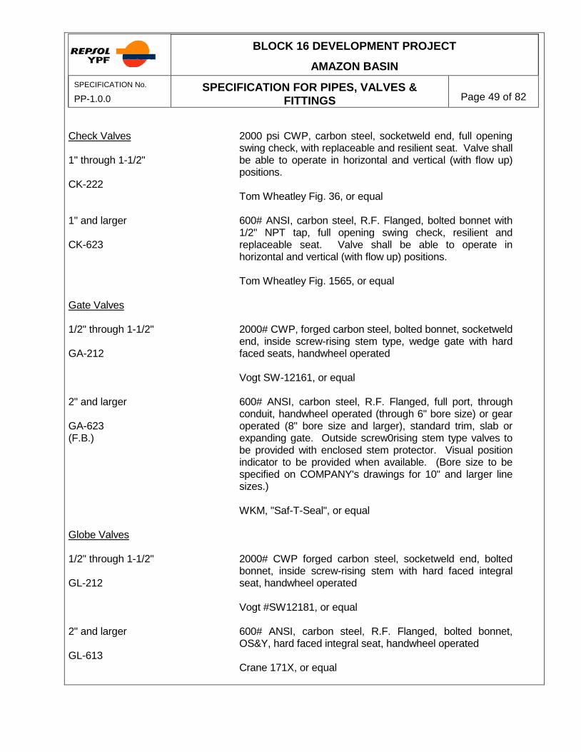
Check Valves 1" through 1-1/2" CK-222 1" and larger CK-623 Gate Valves 1/2" through 1-1/2" GA-212 2" and larger GA-623 (F.B.) Globe Valves 1/2" through 1-1/2" GL-212 2" and larger GL-613
2000 psi CWP, carbon steel, socketweld end, full opening swing check, with replaceable and resilient seat. Valve shall be able to operate in horizontal and vertical (with flow up) positions. Tom Wheatley Fig. 36, or equal 600# ANSI, carbon steel, R.F. Flanged, bolted bonnet with 1/2" NPT tap, full opening swing check, resilient and replaceable seat. Valve shall be able to operate in horizontal and vertical (with flow up) positions. Tom Wheatley Fig. 1565, or equal 2000# CWP, forged carbon steel, bolted bonnet, socketweld end, inside screw-rising stem type, wedge gate with hard faced seats, handwheel operated Vogt SW-12161, or equal 600# ANSI, carbon steel, R.F. Flanged, full port, through conduit, handwheel operated (through 6" bore size) or gear operated (8" bore size and larger), standard trim, slab or expanding gate. Outside screw0rising stem type valves to be provided with enclosed stem protector. Visual position indicator to be provided when available. (Bore size to be specified on COMPANY's drawings for 10" and larger line sizes.) WKM, "Saf-T-Seal", or equal 2000# CWP forged carbon steel, socketweld end, bolted bonnet, inside screw-rising stem with hard faced integral seat, handwheel operated Vogt #SW12181, or equal 600# ANSI, carbon steel, R.F. Flanged, bolted bonnet, OS&Y, hard faced integral seat, handwheel operated Crane 171X, or equal
BLOCK 16 DEVELOPMENT PROJECT
AMAZON BASIN
SPECIFICATION No.
PP-1.0.0 SPECIFICATION FOR PIPES, VALVES &
FITTINGS
Page 50 of 82
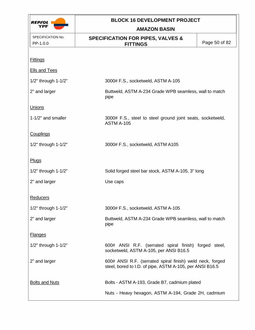
Fittings Ells and Tees 1/2" through 1-1/2" 2" and larger Unions 1-1/2" and smaller Couplings 1/2" through 1-1/2" Plugs 1/2" through 1-1/2" 2" and larger Reducers 1/2" through 1-1/2" 2" and larger Flanges 1/2" through 1-1/2" 2" and larger Bolts and Nuts
3000# F.S., socketweld, ASTM A-105 Buttweld, ASTM A-234 Grade WPB seamless, wall to match pipe 3000# F.S., steel to steel ground joint seats, socketweld, ASTM A-105 3000# F.S., socketweld, ASTM A105 Solid forged steel bar stock, ASTM A-105, 3" long Use caps 3000# F.S., socketweld, ASTM A-105 Buttweld, ASTM A-234 Grade WPB seamless, wall to match pipe 600# ANSI R.F. (serrated spiral finish) forged steel, socketweld, ASTM A-105, per ANSI B16.5 600# ANSI R.F. (serrated spiral finish) weld neck, forged steel, bored to I.D. of pipe, ASTM A-105, per ANSI B16.5 Bolts - ASTM A-193, Grade B7, cadmium plated Nuts - Heavy hexagon, ASTM A-194, Grade 2H, cadmium

BLOCK 16 DEVELOPMENT PROJECT
AMAZON BASIN
SPECIFICATION No.
PP-1.0.0 SPECIFICATION FOR PIPES, VALVES &
FITTINGS
Page 51 of 82
Gaskets Branch Connections
plated 0.175" thick spiral wound 304SS and non-asbestos, flexitallic style CG or equal, with flexite filler (to be 1/8" thick after full compression), 600# rating See paragraph 3.3.13 through 3.3.18 See Figure 01CD

BLOCK 16 DEVELOPMENT PROJECT
AMAZON BASIN
SPECIFICATION No.
PP-1.0.0 SPECIFICATION FOR PIPES, VALVES &
FITTINGS
Page 52 of 82
NOTES (1) Some valves noted in this specification may be limited to less than 200°F service temperatures
as indicated by (°F max.), or may require special seat and/or other seal materials to meet the maximum design pressure rating at temperatures above that indicated for the standard materials by (°F std.). The purchaser should always specify the design pressure rating and maximum service temperature when service temperatures may exceed 150°F.
(2) See paragraph 4.5 for conditions under which API 5L Grade B seamless or ASTM A-53 Grade B
seamless may be substituted if ASTM A-106 Grade B is not available. (3) 1-1/2" and smaller pipe will be socketweld in this class. A socketweld X threaded valve (BA-210)
is specified for instrumentation connections. (4) Flanged end valves of equivalent size, type, and pressure rating listed in this specification are
intended to be interchangeable with respect to face to face dimensions. However, face to face dimensions of random sizes within a manufacturer's product line listed may vary from those of other manufacturers. It is, therefore, the purchaser's responsibility to check these dimensions and to modify the piping drawings prior to fabrication to compensate for any such dimensional variations for the valves purchased.
(5) Provide full opening valve port when COMPANY's valve designation is followed by the suffix
(F.B.) on either the mechanical flow sheet or the piping drawings. (6) Where short radius ells and tees are specified, piping must be derated to 80% WP in
accordance with paragraph 3.5.6.
(7) Sufficient unions shall be provided to allow removal of valves. (8) SERVICE Diesel Flowlines
RATING 900# ANSI R.T.J. - Steel
MAXIMUM DESIGN TEMPERATURE 200
oF
MAXIMUM DESIGN PRESSURE 20 to 100°F; 2220 psig 200°F; 2160 psig PIPE ASTM A106 Grade B Seamless 3/4" and smaller nipples - Schedule 160 1-1/2" and smaller pipe - Schedule 80; PE 2" - 4" pipe - Schedule 80; BE 6" - 24" pipe - Schedule 120; BE Valves

BLOCK 16 DEVELOPMENT PROJECT
AMAZON BASIN
SPECIFICATION No.
PP-1.0.0 SPECIFICATION FOR PIPES, VALVES &
FITTINGS
Page 53 of 82
Ball Valves 1/2" through 1-1/2" BA-512 1/2" through 1-1/2" BA-510 2" through 18" BA-916 2" through 18" BA-926 Check Valves 1/2" through 1-1/2" CK-522 2" and larger CK-926
3000 psi CWP, carbon steel body, 316SS ball and stem, socketweld end, regular port, lever operated. Watts C7351-03-SS-LL, or equal 2500 psi CWP, carbon steel body, 316SS ball and stem, socketweld X threaded, regular port, lever operated Marpac Fig. CS-B790-12-RF-TW 900# ANSI, carbon steel, 316SS ball and stem, R.T.J. flanged end, regular port, lever operated, gear operated (4" and larger), or trunnion mounted ball valve, standard trim. WKM Dynaseal 370, E-4-21-AAF-23, or equal (2"-6") WKM, Dynaseal 370, B-3B-21-AAF-23, or equal (8"-12") Grove Fig. B-5, or equal (14"-18") 900# ANSI, carbon steel, 316SS ball and stem, R.T.J. flanged end, full port, lever operated, gear operated (4" and larger), trunnion mounted ball, standard trim. (Bore size to be specified on COMPANY'S drawings for 10" line sizes and larger). WKM Dynaseal 370, E-4-21-AAF-23, or equal (2"-6") WKM Dynaseal 370, B-3B-21-AAF-23, (full port), or equal (8"-12") Grove Fig. B-5, or equal (14"-18") 3000 psi CWP, carbon steel, socketweld end, full opening swing check, resilient and replaceable seat. Valve shall be able to operate in the horizontal and vertical (with flow up) positions. Tom Wheatley Fig. 36, or equal 900# ANSI, carbon steel, R.T.J. flanged end, full opening swing check, resilient and replaceable seat. Valve shall be

BLOCK 16 DEVELOPMENT PROJECT
AMAZON BASIN
SPECIFICATION No.
PP-1.0.0 SPECIFICATION FOR PIPES, VALVES &
FITTINGS
Page 54 of 82
1" and larger (Pulsating Service) CK-918 Gate Valves 2" and larger GA-916 Globe Valves 1/2" through 3/4" GL-011 1/2" through 1-1/2" GL-012 2" and larger GL-916 Needle Valves 1/2" through 3/4" NE-030
able to perate in horizontal and vertical (with flow up) positions. Tom Wheatley Fig. 1574, or equal 900# ANSI, carbon steel, R.T.J. flanged end, bolted bonnet piston controlled check valve. Valve shall be able to operate in horizontal and vertical (with flow up) positions. Norriseal "Flo-Lift" w/standard trim 900# ANSI carbon steel R.T.J. flanged end, regular port, handwheel operated (through 6" bore size) or gear operated (8" bore size and larger), slab or expanding gate, standard trim. Outside screw-rising stem valves to be furnished with enclosed stem protector. Visual position indicator to be provided when available. (Bore size to be specified on COMPANY'S drawings for 10" line sizes and larger.) WKM, "Saf-T-Seal", or equal 6000 psi CWP, carbon steel, threaded renewable seat, inside screw type, handwheel operated Vogt 3991T, or equal 6000 psi CWP, carbon steel, socketweld end, renewable seat, inside screw type, handwheel operated Vogt SW-3991T, or equal 900# ANSI, carbon steel, R.T.J. flanged end, bolted bonnet, OS&Y with hard faced integral seat, handwheel operated Crane 183, or equal 6000# CWP, 316SS bar stock, soft seat, 1/4" orifice minimum, (3/8" minimum for 3/4" valve), male by female NPT. Specify with extended body for installation in check valve bonnet.
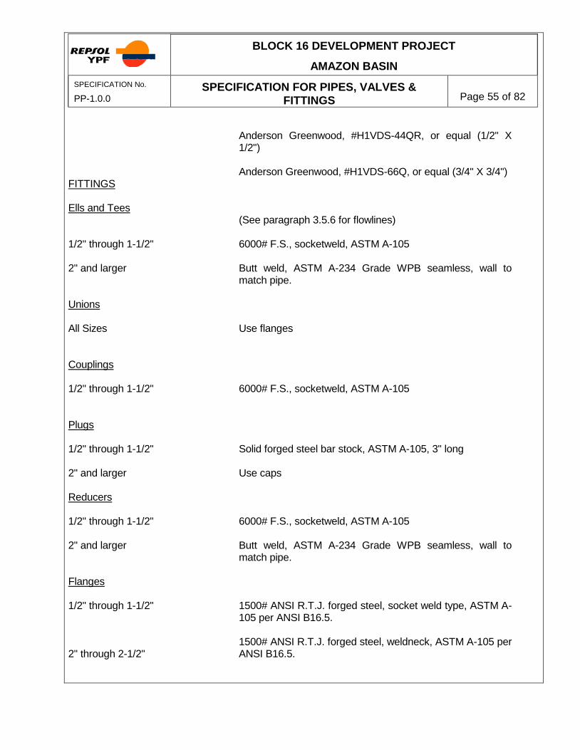
BLOCK 16 DEVELOPMENT PROJECT
AMAZON BASIN
SPECIFICATION No.
PP-1.0.0 SPECIFICATION FOR PIPES, VALVES &
FITTINGS
Page 55 of 82
FITTINGS Ells and Tees 1/2" through 1-1/2" 2" and larger Unions All Sizes Couplings 1/2" through 1-1/2" Plugs 1/2" through 1-1/2" 2" and larger Reducers 1/2" through 1-1/2" 2" and larger Flanges 1/2" through 1-1/2" 2" through 2-1/2"
Anderson Greenwood, #H1VDS-44QR, or equal (1/2" X 1/2") Anderson Greenwood, #H1VDS-66Q, or equal (3/4" X 3/4") (See paragraph 3.5.6 for flowlines) 6000# F.S., socketweld, ASTM A-105 Butt weld, ASTM A-234 Grade WPB seamless, wall to match pipe. Use flanges 6000# F.S., socketweld, ASTM A-105 Solid forged steel bar stock, ASTM A-105, 3" long Use caps 6000# F.S., socketweld, ASTM A-105 Butt weld, ASTM A-234 Grade WPB seamless, wall to match pipe. 1500# ANSI R.T.J. forged steel, socket weld type, ASTM A-105 per ANSI B16.5. 1500# ANSI R.T.J. forged steel, weldneck, ASTM A-105 per ANSI B16.5.

BLOCK 16 DEVELOPMENT PROJECT
AMAZON BASIN
SPECIFICATION No.
PP-1.0.0 SPECIFICATION FOR PIPES, VALVES &
FITTINGS
Page 56 of 82
3" and larger Bolts and Nuts Gaskets Branch Connections
900# ANSI R.T.J. weldneck, forged steel, ASTM A-105 per ANSI B16.5 Bolts - ASTM A-193, Grade B7, cadmium plated Nuts - Heavy hexagon, ASTM A-194, Grade 2H, cadmium plated Class 900, octagonal ring type gasket, annealed 316L SS See paragraphs 3.3.13 through 3.3.18 See Figure 01D

BLOCK 16 DEVELOPMENT PROJECT
AMAZON BASIN
SPECIFICATION No.
PP-1.0.0 SPECIFICATION FOR PIPES, VALVES &
FITTINGS
Page 57 of 82
NOTES (1) Some valves noted in this specification may be limited to less than 200°F service temperatures
as indicated by (°F max.), or may require special seat and/or other seal materials to meet the maximum design pressure rating at temperatures above that indicated for the standard materials by (°F std.). The purchaser should always specify the design pressure rating and maximum service temperature when service temperatures may exceed 150°F.
(2) See paragraph 4.5 for conditions under which API 5L Grade B seamless or ASTM A-53 Grade B
seamless may be substituted if ASTM A-106 Grade B is not available. (3) See paragraph 3.3.11 for definition. Nipples used for the installation of 3/4-inch and smaller
atmospheric vent, drain, sample and test valves as defined in paragraph 3.3.5 (and shown in Figure Q-02A) may be threaded on the downstream end. Such threaded end nipples shall be Schedule 160.
(4) Provide full opening valve port when COMPANY's valve designation is followed by the suffix
(F.B.) on either the mechanical flow sheet or the piping drawings. (5) Where short radius ells and tees are specified, piping must be derated to 80% WP in
accordance with paragraph 3.5.8.

BLOCK 16 DEVELOPMENT PROJECT
AMAZON BASIN
SPECIFICATION No.
PP-1.0.0 SPECIFICATION FOR PIPES, VALVES &
FITTINGS
Page 58 of 82
CLASS "E" SERVICE Injection Water CODE RATING 1500# ANSI R.T.J. - Steel MAXIMUM DESIGN TEMPERATURE 200
oF
MAXIMUM DESIGN PRESSURE** -20 TO 100
oF; 3600 PSIG
150oF; 3540 psig
200oF; 3375 psig
PIPE ASTM A-106 Grade B Seamless 3/4" and smaller nipples - Schedule 160, PE 1-1/2" and smaller pipe - Schedule 160, PE 2" - 16" Pipe - Schedule 160, BE VALVES Ball Valves 1/2" through 1-1/2" Use globe valves or needle valves 2" through 16" 1500# ANSI, carbon steel, R.T.J. flanged regular port, lever or
handwheel operated, (gear operated 4" and larger) trunnion mounted ball valve, standard trim.
BA-1516 WKM Dynaseal 370, E-4-21-AAF-23 (2"-8") Grove Series B-5 (2"-16") 2" through 16" 15000# ANSI carbon steel, R.T.J. flanged end, full port, lever or
handwheel operated (gear operated 4" and larger), trunnion mounted ball valve, standard trim.
BA-1526 Grove, Series B-5 (2"-16") WKM Dynaseal 370, E-4-21-AAF-23 (2"-6") CLASS "E" Check Valves (1) 1/2" through 1'1/2" 3600 psi CWP, carbon steel, socketweld piston check, hard faced
integral seat.

BLOCK 16 DEVELOPMENT PROJECT
AMAZON BASIN
SPECIFICATION No.
PP-1.0.0 SPECIFICATION FOR PIPES, VALVES &
FITTINGS
Page 59 of 82
CK-1512 Vogt, #SW-15701 1-1/2" through 16" 1500#, carbon steel R.T.J. flanged end, full open swing check,
resilient seat. (Purchaser must specify "for vertical flow upward when required by piping configuration.)
CK-1516 Tom Wheatley Fig. 1584 1" and larger 1500# ANSI, carbon steel, R.T.J. flanged end, bolted bonnet,
piston controlled service check valve. Norriseal "Flo-Lift" w/standard trim Gate Valves 1/2" through 1-1/2" 3600 psi CWP, carbon steel, socket weld endes, integral seat,
OS&Y. GA-1512 Vogt #SW1033 2" through 14" 1500# ANSI carbon steel, R.T.J. flanged handwheel operated
(through 6" bore size) or gear operated (8" bore size and larger), flex wedge, standard trim. Outside screw-rising stem valves to be furnished with enclosed stem protector. Visual position indicatior to be provided when available.
GA-1516 Pacific 21555-7-WCB-RJ-(BG) Globe Valves CLASS "E" 1/2" through 1-1/2" 3600 psi CWP, carbon steel, socketweld end, integral hard faced
seat, OS&Y. GL-1512 Vogt SW15821 2"-6" 1500# ANSI, carbon steel, R.T.J. flanged bolted bonnet, integral
seat. GL-1516 Powell 1331-RTJ

BLOCK 16 DEVELOPMENT PROJECT
AMAZON BASIN
SPECIFICATION No.
PP-1.0.0 SPECIFICATION FOR PIPES, VALVES &
FITTINGS
Page 60 of 82
Needle Valves 1/2" through 3/4" 6000 lb. CWP, 316 stainless steel bar stock, soft seat, male by
female NPT, 1/4" orifice minimum (3/8" minimum for 3/4" valve) Anderson Greenwood, HIVDS-44QR (1/2"x1/2") Anderson Green wood, HIVDS 66Q (3/4" x 3/4") FITTINGS Ells and Tess 1/2" through 1-1/2" 6000 lb. F.S., socketweld, ASTM A-105 2" and larger Butt weld, ASTM A-234 Grade WPB seamless, wall to match pipe. Unions All sizes Use Flanges Couplings 1/2" through 1-1/2" 6000 lb. F.S., socketweld, ASTM A-105 Plugs CLASS "E" 1/2" through 1-1/2" Solid forged steel bar stock ATM A-105, 3" long 2" and larger Use caps. Reducers 1/2" through 1-1/2" 6000 lb. F.S., socketweld, ASTM A-105 2" and larger Buttweld, ASTM A-234, Grade WPB, seamless, wall to match pipe FLANGES 1/2" through 1-1/2" 1500# ANSI R.T.J., forged steel socket weld type, ASTM A-105. 2" and larger 1500#ANSI R.T.J. weld neck, forged steel, bored to I.D. of pipe,
ASTM A-105.

BLOCK 16 DEVELOPMENT PROJECT
AMAZON BASIN
SPECIFICATION No.
PP-1.0.0 SPECIFICATION FOR PIPES, VALVES &
FITTINGS
Page 61 of 82
BOLTS AND NUTS Bolts - ASTM A-193, Grade B7, cadmium plated Nuts - heavy hexagon, ASTM A-194, Grade 2H, cadmium plated. GASKETS Class 1500, octagonal ring type gasket, annealed 316L stainless
steel. BRANCH CONNECTIONS See paragraphs 3.3.13 through 3.3.18. See Figure 01E.

BLOCK 16 DEVELOPMENT PROJECT
AMAZON BASIN
SPECIFICATION No.
PP-1.0.0 SPECIFICATION FOR PIPES, VALVES &
FITTINGS
Page 62 of 82
CLASS "E" Notes (1) Some valves noted in this specification may be limited to less than 200
oF service temperatures
as indicated by ( oF max.), or may require special seat and/or other seal materials to meet the
maximum design pressure rating at temperatures above that are indicated for the standard materials by (
oF std.). The purchaser should always specify the design pressure rating and
maximum service temperature when service temperatures may exceed 150oF.
(2) See paragraph 4.5 for conditions under which API 5L Grade B seamless or ASTM A-53 Grade B
seamless may be substituted if ASTM A-106 Grade B is not available. (3) See paragraph 3.3.11 for definition. Nipples used for the installation of 3/4-inch and smaller
atmospheric vent, drain, sample and test valves as defined in paragraph 3.3.5 may be threaded on the downstream end. Such threaded end nipples shall be XXH.
(4) Where short radius ells and tees are specified; piping must be operated to 80% W.P. in
accordance with Paragraph 3.5.8.

BLOCK 16 DEVELOPMENT PROJECT
AMAZON BASIN
SPECIFICATION No.
PP-1.0.0 SPECIFICATION FOR PIPES, VALVES &
FITTINGS
Page 63 of 82
SERVICE Starting Air Firewater Skid Drains Instrument Air Utility Water Potable Water (7) (7) RATING 150# ANSI R.F. Steel (Note some valves limited to 150 psig maximum pressure) MAXIMUM DESIGN TEMPERATURES 150°F MAXIMUM DESIGN PRESSURES -20 to 100°F; 275 psig 150°F; 255 psig PIPE ASTM A106 Grade B Seamless 3" and smaller pipe - Schedule 80; TE or T&C 4" and larger pipe - Standard Weight; BE Note: Potable water and instrument air to be hot dip galvanized. (3" and smaller). VALVES Ball Valves 1/2" through 3" BA-411 2" through 4" BA-113 6" and larger BA-117 2" through 4" BA-123 (F.B.) 6" and larger
1440# minimum CWP, carbon steel body, with 316SS ball and stem, threaded end, fire safe, regular port, lever operated WKM Dynaseal 310, #B-136-CS-02-S1, or equal 150# ANSI carbon steel body, 316SS ball and stem, R.F. flanged end, floating ball, fire safe, regular port, lever operated WKM Dynaseal 310, #B-100-CS-02-S1-HL, or equal 150# ANSI, carbon steel body, 316SS ball and stem, R.F. flanged end, trunnion mounted, fire safe, regular port, lever operated, gear operated (8" and larger). WKM Dynaseal 370, or equal 150# ANSI, carbon steel body, 316SS ball and stem, R.F. flanged end, full port, fire safe, floating ball, lever operated WKM Dynaseal 310, #B-110-CS-02-S1-HL, or equal 150# ANSI, carbon steel body, 316SS ball and stem, R.F.

BLOCK 16 DEVELOPMENT PROJECT
AMAZON BASIN
SPECIFICATION No.
PP-1.0.0 SPECIFICATION FOR PIPES, VALVES &
FITTINGS
Page 64 of 82
BA-127 (F.B.) Butterfly Valves 3" and larger BF-120 Check Valves 1/2" through 3" CK-821 2" and larger CK-123 2" and larger CK-125 Gate Valves 1/2" through 2" GA-411 2" and larger GA-113
flanged end, full port, fire safe, trunnion mounted, lever operated, gear operated (8" and larger). WKM Dynaseal 370 (full port), or equal 150# minimum CWP, lug type Butterfly valve, carbon steel body, for 150# ANSI flanges, 316SS stem, 17-4 disc, lever lock handle (substitute manual gear operator for 8" and larger). May be used only at pressures BELOW 150 psig. WKM A5111-01-S02-13, or equal 800 psig minimum CWP, threaded, carbon steel body, full opening resilient seat check valves. Valve shall be able to operate in the horizontal and vertical (with flow up) positions. Tom Wheatley Fig. 33, or equal 150# ANSI, carbon steel, R.F. flanged, swing check valve with resilient and replaceable seat. Valve shall be able to operate in the horizontal and vertical (with flow up) positions. Tom Wheatley Fig. 1515, or equal 150# ANSI carbon steel wafer type check valve with resilient seal. Valve shall be able to operate in the horizontal and vertical (with flow up) positions. Mission Duo Check #G155SPF, or equal 1440# minimum CWP, forged threaded end, bolted bonnet, inside screw rising stem type, wedge gate with hard faced integral seats, handwheel operated Vogt #12161, or equal 150# ANSI, carbon steel, R.F. flanged end, regular port, handwheel operated (through 10" bore size) or gear operated (12" bore size and larger), renewable seat. Powell 1503N, or equal

BLOCK 16 DEVELOPMENT PROJECT
AMAZON BASIN
SPECIFICATION No.
PP-1.0.0 SPECIFICATION FOR PIPES, VALVES &
FITTINGS
Page 65 of 82
Globe Valves 1/2" through 2" GL-211 3" and larger GL-113 Needle Valves 1/2" through 3/4" NE-030 Fittings (7) Ells and Tees 1/2" through 3" 4" and larger Unions (7) 1/2" through 1-1/2" 2" and larger Couplings (7) 1/2" through 3" Plugs (7) 3" and smaller
1440# minimum CWP, forged carbon steel, threaded, inside screw-rising stem type, hard faced integral seat, bolted bonnet, handwheel operated Vogt #12181, or equal 150# ANSI, carbon steel, R.F. flanged, OS&Y, handwheel operated, renewable seat. Powell #1531, or equal 6000# CWP SS bar stock, soft seat, 1/4" orifice minimum, (3/8" minimum for 3/4" valve), male by female NPT. Specify extended body for installation in check valve bonnets. Anderson Greenwood, #H1VDS-44QR, or equal (1/2" X 1/2") Anderson Greenwood, #H1VDS-66Q, or equal (3/4" X 3/4") 3000# F.S., screwed, ASTM A-105 Butt weld, ASTM A-234 Grade WPB seamless, wall to match pipe 3000# F.S., screwed, ASTM A-105, ground joint, steel to steel seat; or Flexitallic unions. Use flanges 3000# F.S., screwed, ASTM A-105
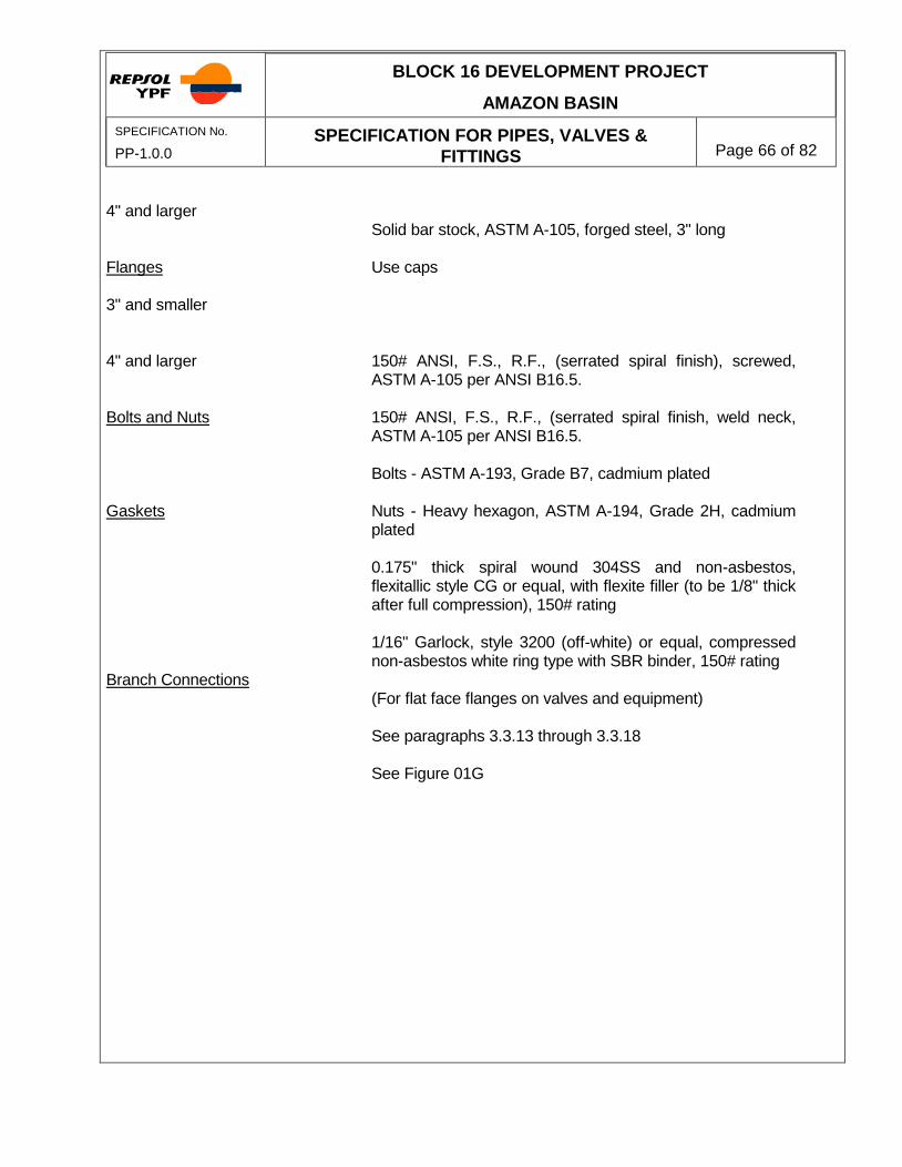
BLOCK 16 DEVELOPMENT PROJECT
AMAZON BASIN
SPECIFICATION No.
PP-1.0.0 SPECIFICATION FOR PIPES, VALVES &
FITTINGS
Page 66 of 82
4" and larger Flanges 3" and smaller 4" and larger Bolts and Nuts Gaskets Branch Connections
Solid bar stock, ASTM A-105, forged steel, 3" long Use caps 150# ANSI, F.S., R.F., (serrated spiral finish), screwed, ASTM A-105 per ANSI B16.5. 150# ANSI, F.S., R.F., (serrated spiral finish, weld neck, ASTM A-105 per ANSI B16.5. Bolts - ASTM A-193, Grade B7, cadmium plated Nuts - Heavy hexagon, ASTM A-194, Grade 2H, cadmium plated 0.175" thick spiral wound 304SS and non-asbestos, flexitallic style CG or equal, with flexite filler (to be 1/8" thick after full compression), 150# rating 1/16" Garlock, style 3200 (off-white) or equal, compressed non-asbestos white ring type with SBR binder, 150# rating (For flat face flanges on valves and equipment) See paragraphs 3.3.13 through 3.3.18 See Figure 01G

BLOCK 16 DEVELOPMENT PROJECT
AMAZON BASIN
SPECIFICATION No.
PP-1.0.0 SPECIFICATION FOR PIPES, VALVES &
FITTINGS
Page 67 of 82
NOTES (1) Some valves noted in this specification may be limited to less than 200°F service temperatures
as indicated by (°F max.), or may require special seat and/or other seal materials to meet the maximum design pressure rating at temperatures above that indicated for the standard materials by (°F std.). The purchaser should always specify the design pressure rating and maximum service temperature when service temperatures may exceed 150°F.
(2) See paragraph 4.5 for conditions under which API 5L Grade B seamless ASTM A-53 Grade B
seamless maybe substituted if ASTM A-106 Grade B is not available. (3) 3" and smaller piping will be threaded in this class. (4) Flanged end valves of equivalent size, type, and pressure rating listed in this specification are
intended to be interchangeable with respect to face to face dimensions. However, face to face dimensions of random sizes within a manufacturer's product line listed may vary from those of other manufacturers. It is, therefore, the purchaser's responsibility to check these dimensions and to modify the piping drawings prior to fabrication to compensate for any such dimensional variations for the valves purchased.
(5) Provide full opening valve port when COMPANY's valve designation is followed by the suffix
(F.B.) on either the mechanical flow sheet or the piping drawings. (6) Where short radius ells and tees are specified, piping must be derated to 80% WP in
accordance with paragraph 3.5.6. (7) For potable water service and instrument air service, all piping shall be hot dip galvanized.

BLOCK 16 DEVELOPMENT PROJECT
AMAZON BASIN
SPECIFICATION No.
PP-1.0.0 SPECIFICATION FOR PIPES, VALVES &
FITTINGS
Page 68 of 82
SERVICE Heating Oils CODE RATING ANSI 300# R.F. Steel MAXIMUM DESIGN TEMPERATURE 650°F MAXIMUM DESIGN PRESSURES -20 to 100°F; 720 psig 550°F; 575 psig 650°F; 535 psig PIPE ASTM A-106 Grade B Seamless 3/4" and smaller nipples - Schedule 160 1-1/2" and smaller pipe - Schedule 80, PE 2" pipe - Schedule 80, BE 3" - 14" - Standard Weight, BE 16" - 18" - Schedule 40, BE

BLOCK 16 DEVELOPMENT PROJECT
AMAZON BASIN
SPECIFICATION No.
PP-1.0.0 SPECIFICATION FOR PIPES, VALVES &
FITTINGS
Page 69 of 82
VALVES Ball Valves 1/2" through 1-1/2" BA-852 (F.B.) 1/2" through 1-1/2" BA-850 2" through 12" BA-353 (F.B.) Check Valves 1-1/2" and smaller CK-252 2" and larger CK-353 Gate Valves 1-1/2" and smaller GA-212 1/2"-1" GA-210
(Do not use for temperatures above maximum indicated) 1000 psi CWP, forged carbon steel body with 316SS ball and stem, full port, socketweld, high temperature metal trim, lever operated Worcester #PT59-4-6-G-G-SW 1000 psi CWP, forged carbon steel body with 316SS ball and stem, reduced port, socketweld X threaded, high temperature metal trim, lever operated Worcester #PT44-4-6-G-G-SWXSE 300# ANSI R.F., flanged, cast carbon steel, high temperature trim, full port, handwheel operated, gear operated (8" and larger)
Orbit No. 1223H8 (800°F) (full opening), or equal
2000# socketweld, forged carbon steel, swing check standard trim, bolted bonnet Vogt #SW4835, or equal 300# ANSI, R.F., flanged, cast carbon steel, bolted bonnet with 1/2" NPT tap, standard trim, special for high temperature service. Lunkenheimer Fig. 3072, or equal 2000# CWP, forged carbon steel, bolted bonnet, inside screw, socketweld ends, with hard faced seats, handwheel operated Vogt #SW12161, or equal 1975# CWP, forged carbon steel, welded bonnet, OS&Y, socketweld x threaded ends, with hard faced seats,

BLOCK 16 DEVELOPMENT PROJECT
AMAZON BASIN
SPECIFICATION No.
PP-1.0.0 SPECIFICATION FOR PIPES, VALVES &
FITTINGS
Page 70 of 82
2" and larger GA-353 Globe Valves 1/2" through 1-1/2" GL-212 2" and larger GL-353 Fittings Ells and Tees 1-1/2" and smaller 2" and larger Unions All Sizes Couplings 1-1/2" and smaller Plugs 1-1/2" and smaller 2" and larger
handwheel operated. 300# ANSI, R.F., flanged, cast carbon steel, handwheel operated, bolted bonnet, OS&Y, gear operated (12" and up). Crane No. 33XU, or equal 2000# CWP, socketweld, forged carbon steel, bolted bonnet, integral hard face seat, handwheel operated Vogt #SW12181, or equal 300# ANSI R.F., flanged cast carbon steel, bolted bonnet, OS&Y, handwheel operated Crane No. 151XU, or equal 3000# F.S., socketweld, ASTM A-105 Butt weld, ASTM A-234 Grade WPB seamless, wall to match pipe Use flanges. 3000# F.S., socketweld, ASTM A-105 Solid round bar stock, F.S., ASTM A-105, 3" long Use caps

BLOCK 16 DEVELOPMENT PROJECT
AMAZON BASIN
SPECIFICATION No.
PP-1.0.0 SPECIFICATION FOR PIPES, VALVES &
FITTINGS
Page 71 of 82
Reducers 1-1/2" and smaller Flanges 1-1/2" and smaller 2" and larger Bolts and Nuts Gaskets Branch Connections
3000# F.S. socketweld, ASTM A-105 300# ANSI R.F., (serrated spiral finish), F.S. socketweld, ASTM A-105 per B16.5 300# ANSI R.F., (serrated spiral finish), F.S. weld neck, ASTM A-105 per B16.5 Bolts - ASTM A-193, Grade B7, cadmium plated Nuts - Heavy hexagon, ASTM A-194, Grade 2H, cadmium plated 0.175" thick spiral wound 304SS and non-asbestos, flexitallic style CG or equal, with flexite filler (to be 1/8" thick after full compression), 300# rating 1/16" Garlock HTC 9850, or equal, compressed non-asbestos carbon fiber gasket with nitrile binder (For flat face flanges on valves and equipment) See paragraphs 3.3.13 through 3.3.18 See Figure 01H

BLOCK 16 DEVELOPMENT PROJECT
AMAZON BASIN
SPECIFICATION No.
PP-1.0.0 SPECIFICATION FOR PIPES, VALVES &
FITTINGS
Page 72 of 82
NOTES 1. Some valves noted in this specification may be limited to less than 200°F service temperatures
as indicated by (°F max.), or may require special seat and/or other seal materials to meet the maximum design pressure rating at temperatures above that indicated for the standard materials by ( °F std.). The purchaser should always specify the design pressure rating and maximum service temperature when service temperatures may exceed 150°F.
2. See paragraph 4.5 for conditions under which API 5L Grade B seamless ASTM A-53 Grade B
seamless maybe substituted if ASTM A-106 Grade B is not available. 3. See paragraph 3.3.11 for definition. Nipples used for the installation of 3/4-inch and smaller
atmospheric vent, drain, sample and test valves as defined in paragraph 3.3.5 (and shown in Figure 02A) may be threaded on both ends. Such threaded end nipples shall be Schedule 160.
4. Flanged end valves of equivalent size, type, and pressure rating listed in this specification are
intended to be interchangeable with respect to face to face dimensions. However, face to face dimensions of random sizes within a manufacturer's product line listed may vary from those of other manufacturers. It is, therefore, the purchaser's responsibility to check these dimensions and to modify the piping drawings prior to fabrication to compensate for any such dimensional variations for the valves purchased.
5. Provide full opening valve port when COMPANY's valve designation is followed by the suffix
(F.B.) on either the mechanical flow sheet or the piping drawings. 6. Where short radius ells and tees are specified, piping must be derated to 80% WP in
accordance with paragraph 3.5.6.

BLOCK 16 DEVELOPMENT PROJECT
AMAZON BASIN
SPECIFICATION No.
PP-1.0.0 SPECIFICATION FOR PIPES, VALVES &
FITTINGS
Page 73 of 82
SERVICE Lube Oil, Chemical Injection (For Class "C" and below) RATING 600# ANSI Class MAXIMUM DESIGN TEMPERATURE 230°F MAXIMUM DESIGN PRESSURES -20 to 100°F; 1440 psig 150°F; 1415 psig 200°F; 1350 psig 230°F; 800 psig TUBING ASTM A-269 TP 316 seamless stainless steel, suitable for bending or flaring, free from
rust or scale, oiled inside and outside, packed flat with ends plugged for shipment. 1/4" and 3/8" - 0.035" wall 1/2" - 0.049" wall 3/4" and 1" - 0.065" wall 1-1/4" and 1-1/2" - 0.095" wall Ball Valves 1/2" through 1-1/2" BA-431 1/2" through 1-1/2" BA-441 (F.B.) Check Valves 1/2" through 1-1/2" CK-441 Globe Valves 1/2" through 1-1/2" GL-231
1440 psi CWP, stainless steel body, ball and stem, threaded end, regular port, lever operated WKM 310, B-136-S8-02-S1, or equal 1440 psi CWP, stainless steel body, ball and stem, threaded end, full port, lever operated WKM 310, B-138-S8-02-S1, or equal 6000 psi CWP, Female NPT ends, 316SS body, poppet check valve, viton seal, 5 psig cracking pressure. Nupro Fig. SS-CH___F___-5 1440 psi CWP, forged stainless steel, threaded end, inside screw-rising stem, bolted bonnet, hard faced integral seat, handwheel operated Vogt #12501, or equal

BLOCK 16 DEVELOPMENT PROJECT
AMAZON BASIN
SPECIFICATION No.
PP-1.0.0 SPECIFICATION FOR PIPES, VALVES &
FITTINGS
Page 74 of 82
Needle Valves 1/2", 3/4" NE-030 Fittings 1-1/2" and down Unions 1-1/2" and down Flanges 1-1/2" and down Bolts and Nuts Gaskets Branch Connections
6000 psi CWP, 316SS bar stock, soft seat, 1/4" orifice minimum (3/8" for 3/4" valve), male by female NPT. Specify extended body (L) for installation in check valve bonnet. Anderson Greenwood H1VDS-44QR, or equal (1/2" X 1/2") Anderson Greenwood H1VDS-66Q, or equal (3/4" X 3/4") Compression type, 316SS, "Swagelok", or equal Compression type, 316SS, "Swagelok", or equal (Used only when connecting to flanged equipment or valves) 600# ANSI R.F. (serrated spiral finish), stainless steel, screwed, ASTM A182 F316L, per ANSI B16.5 Bolts - ASTM A-193, Grade B7, cadmium plated Nuts - Heavy hexagon, ASTM A-194, Grade 2H, cadmium plated 0.175" thick spiral wound 316SS and non-asbestos, flexitallic style CG or equal, with flexite filler (to be 1/8" thick after full compression), 600# rating (Use Swagelok fittings)

BLOCK 16 DEVELOPMENT PROJECT
AMAZON BASIN
SPECIFICATION No.
PP-1.0.0 SPECIFICATION FOR PIPES, VALVES &
FITTINGS
Page 75 of 82
SERVICE Chemical Injection (For Class "D" and Class "L") RATING 1500# ANSI Class MAXIMUM DESIGN TEMPERATURE 300°F MAXIMUM DESIGN PRESSURES -20 to 100°F; 3600 psig 300°F; 3000 psig TUBING ASTM A-269 TP 316 seamless stainless steel, suitable for bending or flaring, free from
rust or scale, oiled inside and outside, packed flat with ends plugged for shipment. 1/4" - 0.035" wall 3/8" - 0.049" wall 1/2" - 0.065" wall 3/4" - 0.095" wall 1" - 0.12" wall Gate Valves 1/2" through 1" GA-531 Check Valves 1/2" through 1" CK-440 Needle Valves 1/2", 3/4" NE-030
3600 psi CWP, stainless steel body, threaded end, OS&Y, bolted bonnet, handwheel operated, solid wedge gate Vogt 15401, or equal 6000 psi CWP, Swagelok tube fitting ends, 316SS body, poppet check valve, viton seal, 5 psig cracking pressure. Nupro Fig. SS-CHS ___-5 6000 psi CWP, 316SS bar stock, soft seat, 1/4" orifice minimum (3/8" for 3/4" valve), male by female NPT. Specify extended body (L) for installation in check valve bonnet. Anderson Greenwood H1VDS-44QR, or equal (1/2" X 1/2") Anderson Greenwood H1VDS-66Q, or equal (3/4" X 3/4")

BLOCK 16 DEVELOPMENT PROJECT
AMAZON BASIN
SPECIFICATION No.
PP-1.0.0 SPECIFICATION FOR PIPES, VALVES &
FITTINGS
Page 76 of 82
Fittings 1" and down Unions 1" and down Flanges 1" and down Bolts and Nuts Gaskets Branch Connections
Compression type, 316SS, "Swagelok", or equal Compression type, 316SS, "Swagelok", or equal (Used only when connecting to flanged equipment or valves) 1500# ANSI R.F. (serrated spiral finish), stainless steel, screwed, ASTM A182 F316L, per ANSI B16.5 Bolts - ASTM A-193, Grade B7, cadmium plated Nuts - Heavy hexagon, ASTM A-194, Grade 2H, cadmium plated 0.175" thick spiral wound 316SS and non-asbestos, flexitallic style CG or equal, with flexite filler (to be 1/8" thick after full compression), 1500# rating (Use Swagelok fittings)
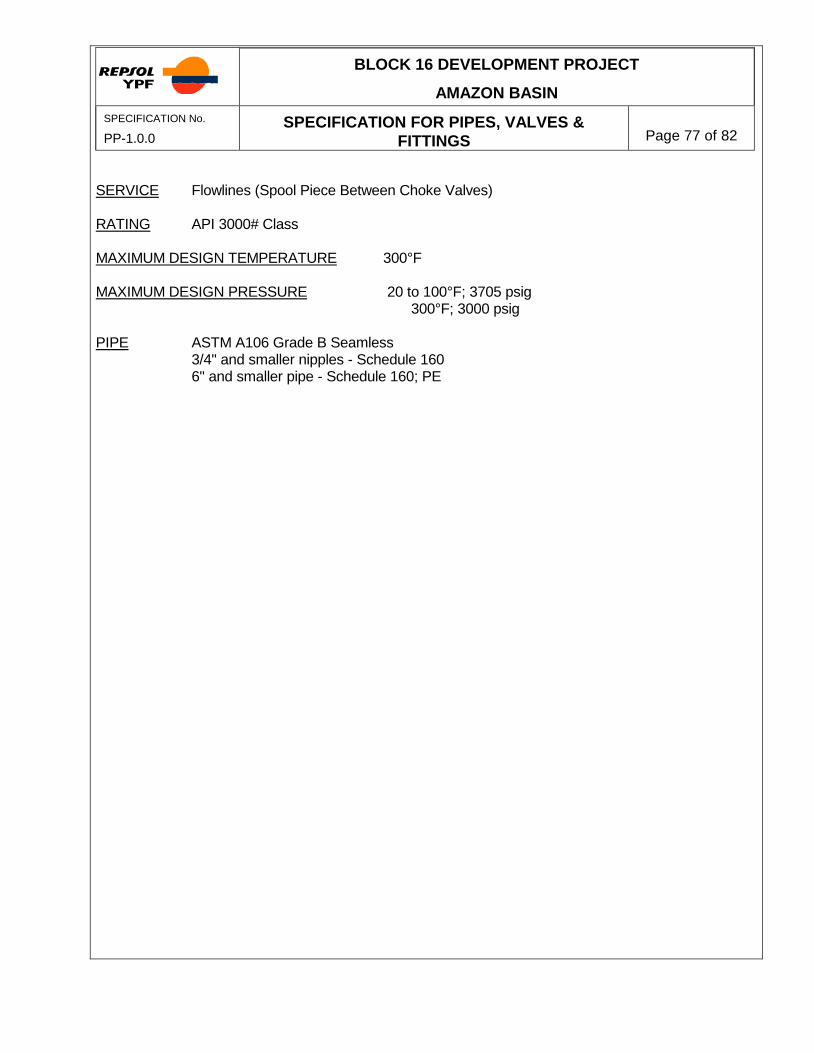
BLOCK 16 DEVELOPMENT PROJECT
AMAZON BASIN
SPECIFICATION No.
PP-1.0.0 SPECIFICATION FOR PIPES, VALVES &
FITTINGS
Page 77 of 82
SERVICE Flowlines (Spool Piece Between Choke Valves) RATING API 3000# Class MAXIMUM DESIGN TEMPERATURE 300°F MAXIMUM DESIGN PRESSURE 20 to 100°F; 3705 psig 300°F; 3000 psig PIPE ASTM A106 Grade B Seamless 3/4" and smaller nipples - Schedule 160 6" and smaller pipe - Schedule 160; PE

BLOCK 16 DEVELOPMENT PROJECT
AMAZON BASIN
SPECIFICATION No.
PP-1.0.0 SPECIFICATION FOR PIPES, VALVES &
FITTINGS
Page 78 of 82
SERVICE Hydraulic Oil (Between Hydraulic Start-ups and Turbine Generators) RATING 300# ANSI MAXIMUM DESIGN TEMPERATURE 200
oF
MAXIMUM DESIGN PRESSURE -20 to 200
oF; 400 psig
PIPE ASTM A-312 TP-316L Welded 1/2" - 1-1/2" Pipe Schedule 40S, PE FITTINGS Ells and Tees 1/2" through 1-1/2" 3000# F.S., socketweld, ASTM A-182, F316L, per ANSI B16.11 Unions Use Flanges for all sizes Couplings 1/2" through 1-1/2" 3000# F.S., socketweld, ASTM A-182, F316L Plugs 1/2" through 1-1/2" Solid bar stock, ASTM A-182, F316L, forged steel, 3" long. Reducers 1/2" through 1-1/2" 3000# F.S., socketweld, ASTM A-182, F316L Flanges 1/2" through 1-1/2" Meeting SAE Code 61 (Provided by Vendor) Bolts and Nuts (Provided by Vendor) Gasket O-Ring (Provided by Vendor) Branch Connections None required

BLOCK 16 DEVELOPMENT PROJECT
AMAZON BASIN
SPECIFICATION No.
PP-1.0.0 SPECIFICATION FOR PIPES, VALVES &
FITTINGS
Page 79 of 82
SERVICE Hydraulic Oil (Between Hydraulic Start-ups and Turbine
Generators) RATING Special - See design ratings below MAXIMUM DESIGN TEMPERATURE 160
oF
MAXIMUM DESIGN PRESSURE -20 to 160
oF; 5200 psig
PIPE ASTM A-312 TP-316 Seamless 1/2" - 1-1/2" Pipe Schedule 160s, PE FITTINGS Ells and Tees 1/2" through 1-1/2" 6000# F.S., socketweld, ASTM A-182, F316L, per ANSI B16.11 Unions Use Flanges for all sizes Couplings 1/2" through 1-1/2" 6000# F.S., socketweld, ASTM A-182, F316L Plugs 1/2" through 1-1/2" Solid bar stock, ASTM A-182, F316L, forged steel, 3" long. Reducers 1/2" through 1-1/2" 6000# F.S., socketweld, ASTM A-182, F316L Flanges 1/2" through 1-1/2" Meeting SAE Code 62 (Provided by Vendor) Bolts and Nuts (Provided by Vendor) Gaskets O-Ring (Provided by Vendor) Branch Connections None required Reducers 1/2" through 1-1/2" 6000# F.S., socketweld, ASTM A-182, F316L

BLOCK 16 DEVELOPMENT PROJECT
AMAZON BASIN
SPECIFICATION No.
PP-1.0.0 SPECIFICATION FOR PIPES, VALVES &
FITTINGS
Page 80 of 82
Flanges 1/2" through 1-1/2" Meeting SAE Code 62 (Provided by Vendor) Bolts and Nuts (Provided by Vendor) Gaskets O-Ring (Provided by Vendor) Branch Connections None required
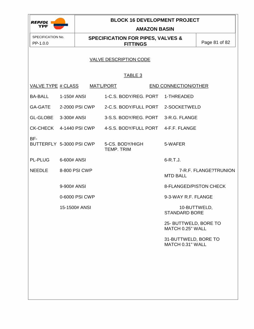
BLOCK 16 DEVELOPMENT PROJECT
AMAZON BASIN
SPECIFICATION No.
PP-1.0.0 SPECIFICATION FOR PIPES, VALVES &
FITTINGS
Page 81 of 82
VALVE DESCRIPTION CODE
TABLE 3
VALVE TYPE # CLASS MAT'L/PORT END CONNECTION/OTHER BA-BALL 1-150# ANSI 1-C.S. BODY/REG. PORT 1-THREADED GA-GATE 2-2000 PSI CWP 2-C.S. BODY/FULL PORT 2-SOCKETWELD GL-GLOBE 3-300# ANSI 3-S.S. BODY/REG. PORT 3-R.G. FLANGE CK-CHECK 4-1440 PSI CWP 4-S.S. BODY/FULL PORT 4-F.F. FLANGE BF- BUTTERFLY 5-3000 PSI CWP 5-CS. BODY/HIGH 5-WAFER TEMP. TRIM PL-PLUG 6-600# ANSI 6-R.T.J. NEEDLE 8-800 PSI CWP 7-R.F. FLANGE?TRUNION
MTD BALL 9-900# ANSI 8-FLANGED/PISTON CHECK 0-6000 PSI CWP 9-3-WAY R.F. FLANGE 15-1500# ANSI 10-BUTTWELD,
STANDARD BORE 25- BUTTWELD, BORE TO
MATCH 0.25" WALL 31-BUTTWELD, BORE TO
MATCH 0.31" WALL

BLOCK 16 DEVELOPMENT PROJECT
AMAZON BASIN
SPECIFICATION No.
PP-1.0.0 SPECIFICATION FOR PIPES, VALVES &
FITTINGS
Page 82 of 82
VALVE DESCRIPTION CODE 70-BUTTWELD, TRUNION
MOUNTED BALL, STANDARD BORE
78-BUTTWELD, TRUNNION
MOUNTED BALL, STANDARD BORE
80-BUTTWELD, SCHEDULE 80
BORE 0-OTHER Note: UG is the designation for underground valves. The other codes do not apply to UG valves.


![kiswok.comkiswok.com/docs/Kiswok Fast Fix.pdfDI valves], cover' also 'available,. 'CM'L-5Æ43552. Ductile Iron Pipe Fittings Sluice Valves IS 153B Cast Iron Pipe Fittings KISWOK FAST](https://static.fdocuments.us/doc/165x107/5b180c797f8b9a37258b7375/fast-fixpdfdi-valves-cover-also-available-cml-5a43552-ductile-iron-pipe.jpg)
