pipe hanger
119
AAA TECHNOLOGY & SPECIALTIES CO., INC. 6219 Brimoore Road, Houston, Texas 77041-5114, U.S.A. Telephone: 713-849-3366; FAX: 713-849-3654 E-mail: [email protected]; Website: hp://www.aaatech.com AAA TECHNOLOGY & SPECIALTIES CO., INC. PRODUCT CATALOG 2012 www.aaatech.com TOTAL SOLUTION SERVICE For the Industrial Piping Marketplace 41 YEARS SERVING INDUSTRY
-
Upload
tuzlucayir -
Category
Documents
-
view
280 -
download
22
Transcript of pipe hanger

AAA TECHNOLOGY & SPECIALTIES CO., INC. 6219 Brittmoore Road, Houston, Texas 77041-5114, U.S.A.
Telephone: 713-849-3366; FAX: 713-849-3654 E-mail: [email protected]; Website: http://www.aaatech.com
A A A T E C H N O L O G Y
& SPECIALTIES CO., INC.
P R O D U C T C A T A L O G
2012
www.aaatech.com
TOTAL SOLUTION SERVICE
For the Industrial Piping Marketplace
4 1 Y E A R S S E R V I N G I N D U S T R Y

713-849-3366 | www.aaatech.com | [email protected] AAA Technology & Specialties Co., Inc. Page 229
TERMS AND CONDITIONS
1. PARTIES: The parties to these terms and conditions of sale are: Buyer, the purchasing
party, and AAA Technology and Specialties Co., Inc., hereinafter referred to as AAAT, the
selling party.
2. CONTROLLING PROVISIONS: These terms and conditions with respect to any sale of
products by AAAT to Buyer whether or not Buyer issues a purchase order for the prod-
ucts. No Waiver, alteration or modification of these terms and conditions whether on
Buyer purchase order or otherwise shall be valid unless the waiver, alteration and modifi-
cation is specially accepted in writing and signed by an authorized representative (Officer)
of AAAT.
3. FREIGHT: Unless otherwise stated, all prices for materials and F.O.B. Point of ship-
ment.
4. PRICES AND DESIGNS: Prices and designs are subject to change without notice. AAAT
is not responsible for typographical errors.
5. DELIVERY: AAAT will make every effort to complete delivery of products as quoted
and as indicated on AAAT’s acceptance of an order from Buyer, however AAAT assumes
no responsibility or liability and will accept no back charge, for loss or damage due to
delays or inability to deliver such products caused by acts of God, war, labor difficulties,
accident, delays of carriers, by contractors or suppliers, inability to obtain materials, or
any other causes beyond the control of AAAT and continues for a period of sixty (60) days,
AAAT by written notice to Buyer, may terminate any such contract of sale of its products
without liability of any nature. Under no circumstances shall AAAT be liable for any
special or consequential damage or for loss, damage, or expense (whether or not based
on negligence) directly or indirectly arising from delays or failure to give notice of delay.
6. DELAYS: Delays due to lack of purchase order issuance or the submittal or required
information or design information which result in inability to meet scheduled dates shall
result in said dates being extended.
7. SHIPMENTS: All products shipped will be carefully examined, counted and packed.
The cost of any special packing or special handling caused by Buyer’s requirements or
requests shall be added to the amount of the order. No claim for storages will be allowed
unless made and properly documented in writing within ten (10) days of receipt of ship-
ment. Claims for products damaged or lost in transit should be made on the carrier, as
AAAT’s responsibility ceases, and title passes, on delivery to the carrier.
8. SPECIAL PRODUCTS: Orders covering special or non standard products are not subject
to cancellation except on such terms as AAAT may specify upon written request from
Buyer.
9. RETURNS: Prior to returning any products to AAAT. All items shipped to AAAT without
permission to do so will not be accepted. All products approved for return to AAAT will
be subject to the following: (a) All material returned must, on its arrival at AAAT’s facili-
ties, be found to be in first-class condition: If not, cost of putting in salable condition will
be deducted from credit memoranda, (b) A handling charge of twenty percent (20%) of
the original price paid by Buyer will be deducted from all credit memoranda issued for
material returned and (c) Transportation charges, if not prepaid, will be deducted from
credit memoranda.
10. WARRANTY: AAAT warrants for one year from the date of shipment all products
AAAT manufactured to the extent that AAAT will replace those having defects in material
or workmanship when used for the purpose and in the manner in which AAAT recom-
mends. Claim for breach of the above warranty must be submitted in writing within thirty
(30) days from the date the material was determined by Buyer to be defective or, in any
event, within twelve (12) months from the date of delivery to the original user, unless
otherwise stated. If AAAT’s examination shall disclose to its satisfaction that the
product’s are defective, and an adjustment is required, the amount of such adjustment
shall not exceed the net sales price of the defective products only and no allowance will
be made for labor or expense of repairing or replacing defective products or workman-
ship or damage resulting from the same. AAAT warrants the products which it sells of
other manufacturers only to the extent that they are warranted to AAAT by the supplier.
Where engineering design or fabrication work is supplied, Buyer’s acceptance of AAAT’s
design or delivery of AAAT’s work shall relieve AAAT of all further obligation, other than
as expressed in AAAT’s product warranty. THIS IS AAAT’S SOLE AND EXCLUSIVE WAR-
TRANTY. AAAT MAKES NO OTHER WARRANTY OF ANY KIND, EXPRESSED OR IMPLIED
AND ALL IMPLIED WARRANTIES OF MERCHANTABILITY AND FITNESS FOR A PARTICULAR
PURPOSE WHICH EXCEED AAAT’S AFORESTATED OBLIGATION ARE HEREBY DESCLAIMED
BY AAAT AND EXCLUDED FROM THIS WARRANTY. IN NO EVENT AND UNDER NO CIRCUM-
STANCES WILL AAAT BE LIABLE FOR PERSINAL INJURY OR PROPERTY DAMAGE ARISING IN
ANY MANNER OUT OF THE USE OR APPLICATION OF THE PRODUCTS AND SERVICES OF
AAAT. UNDER NO CIRCUMSTANCES, AND IN NO EVENT WILL AAAT BE LIABLE FOR CONSE-
QUENTIAL, SPECIAL OR INCIDENTAL DAMAGES WHETHER FOR BREACH OF CONTRACT OR
WARRANTY, NEGLIGENCE OR ANY OTHER TORTUOUS ACT OR OMISSION.
The terms of this warranty can be modified or changed only in writing by an authorized
representative (officer) or AAAT. AAAT neither assumes, nor authorizes any person to
assume for it, any other obligation in connection with the sale of its engineering designs
of products. This warranty shall not apply to any products or parts of products which
been (a) repaired or altered outside of AAAT’s facilities. In any manner: or (b) have been
subjected to misuse, negligence or accidents: or (c) have recommendation. AAAT shall
not be responsible for design errors due to inaccurate or incomplete information supplied
by Buyer or its representatives.
11. PRODUCT APPLICATION AND INDEMNIFICATION: AAAT’s products are strictly in-
tended for installation and service as illustrated or described in its catalog. AAAT is aware
that pipe hanger products have been used successfully for purposes other than for which
they were intended or designed. AAAT also know that on occasion pipe hanger products
have failed when used as tools of erection or for some purpose other than for which they
were designed.
Examples of misapplications which can result in failure include: failure to remove travel
stops before putting the piping system on line, or failure to lock spring hangers into a
solid position prior to hydrostatic testing: the use of a beam clamp on a beam other than
described in the catalog: and the suspension of clevis hangers, one under another, which
can result in an accumulative load greater than the pipe hanger will support. These
instances are by way of example only and are not intended to be all inclusive of the man-
ner in which misapplication may occur.
Pipe hanger products are produced in accordance with industry codes and standards.
Anyone using AAAT hanger products should employ good engineering judgment, follow
industry standard practices, exercise reasonable care and follow all necessary safety
procedures to avoid accidents. AAAT shall not be responsible for any losses or damage
sustained by the Buyer or any other person as a result of misapplication.
Buyer shall defend, indemnify, and save AAAT harmless from any and all liability or al-
leged liability, expenses, including legal fees arising from personal injuries including death
or damage to property caused by reason of improper and/or negligent installation of
pipe hangers designed and fabricated by AAAT.
12. TAXES: The amount of any sales, excise or other taxes, if any, applicable to the prod-
ucts covered by this order, shall be added to the purchase price and shall be paid by
Buyer unless Buyer provides Seller with an exemption certificate acceptable to the taxing
authorities.
13. MINIMUM INVOICE: $50.00 PLUS transportation.
14. TERMS: Cash, net 30 days plus on and one half percent (1 ½%) interest per month on
the unpaid balance thereafter.

713-849-3366 | www.aaatech.com | [email protected] Page 228
PLEASE INQUIRE ABOUT THESE OTHER QUALITY
AAA TECHNOLOGY PRODUCTS
TRI-FOAM™
MOLDED POLYURETHANE FOAM
COLD SHOES AND SADDLES
TRI-CAL™
CALCIUM SILICATE
HOT SHOES AND SADDLES
AAA Technology & Specialties Co., Inc.
TABLE OF CONTENTS
Introduction i
Core Product Categories ii
General Notes iii
Parts Overview 2
EQUAL™ Variable Spring Hangers 15
Series E82 24
Series E268 28
Series E98 32
Series E100 36
Series E110 40
EQUALBALANCE™ Constant Effort Supports 44
Sway Struts 72
Sway Braces 85
Hydraulic Snubbers 89
Hardware – Pipe Hangers and Supports 93
General Hardware 93
Clevis and Band Hangers 130
Pipe Clamps – 2 and 3 Bolt 145
Pipe Rollers Supports 161
Vibration Control – Hold Down Clamps 184
Pipe Shoes 193
TRI*SLIDE™ Low Friction Slide Bearings 216
Corrosion Resistance Products 224
TRI*WEAR™ FRP Wear Pads 224
TRI*COMPOSITE™ – Molded Insulated Supports 225
TRI*GUARD™ - Thermoplastic Supports 227
Terms and Conditions 229

713-849-3366 | www.aaatech.com | [email protected]
AAA Technology & Specialties Co., Inc. Page 227
CORROSION RESISTANCE PRODUCTS
Corrosion between pipe supports and pipe at metal to metal contact points is a common problem in the process industry. TRI•GUARD™ thermoplastic bars placed under the pipe and around U-bolts, when lateral pipe restraint is required, eliminate most metal to metal con-tact and therefore the resultant corrosion. With TRI•GUARD™, water no longer pools on pipe support surfaces under the pipe. Water runs off due to the TRI•GUARD™ shape. TRI•GUARD™ prevents electrical conductivity between the pipe and the pipe support member. TRI•BAR™ can be used at operating temperatures up to 250°F (120°C) and under all pipe diameters up to 48”. TRI•BAR™ is available for higher temperature applications, howev-er corrosion is generally not an issue on higher temperature piping systems. See our TRI•BOLT™ product line for coated U-bolts to be used with TRI•GUARD™ supports when lateral restraint is required.
TRI*GUARD™
DURABLE THERMOPLASTIC SUPPORTS
Nominal Pipe Size
(IN)
U-Bolt Leg C-C "B" (IN)
Bar Length "L" (IN)
Bar Hole Diam
"G" (IN)
Bar Size "D" (IN)
Bar Height "H" (IN)
3/4 1 5/8 3 3/8 3/4 1/32
1 1 3/4 3 1/2 1 7/16
1 1/2 2 3/8 4 1/2 1 7/16
2 2 13/16 4 1/2 1/2 1 7/16
3 4 1/16 6 5/8 1 7/16
4 5 1/16 7 5/8 1 7/16
6 7 3/8 9 11/16 1 7/16
8 9 3/8 11 11/16 1 7/16
10 11 5/8 13 1/2 7/8 1 1/2 11/16
12 13 3/4 16 1 1 1/2 11/16
14 15 17 1 1 1/2 11/16
16 17 19 1 1 1/2 11/16
18 19 1/8 21 1/2 1 1/8 1 1/2 11/16
20 21 1/8 23 1/2 1 1/8 1 1/2 11/16
24 25 1/8 27 1/2 1 1/8 1 1/2 11/16
330 31 1/8 33 1/2 1 1/8 1 1/2 11/16
36 37 1/8 39 1/2 1 1/8 1 1/2 11/16

713-849-3366 | www.aaatech.com | [email protected] Page 226
CORROSION RESISTANCE PRODUCTS
TRI*COMPOSITE
MOLDED INSULATED SUPPORTS CONTINUED
Description Pipe Size
(“) Thickness
(“) Angle
(⁰) Length (“) Material
TW-.75-.25-60-6-V 3/4 1/4 60 6 Vinyl Ester
TW-1.0-.25-90-12-V 1 1/4 90 12 Vinyl Ester
TW-1.5-.25-120-18-E 1 1/2 1/4 120 18 Epoxy
TW-2.0-.25-180-24-V 2 1/4 180 24 Vinyl Ester
TW-2.5-.25-60-6-V 2 1/2 1/4 60 6 Vinyl Ester
TW-3.0-.25-90-12-E 3 1/4 90 12 Epoxy
TW-3.5-.25-120-18-V 3 1/2 1/4 120 18 Vinyl Ester
TW-4.0-.25-180-24-V 4 1/4 180 24 Vinyl Ester
TW-4.5-.25-60-6-E 4 1/2 1/4 60 6 Epoxy
TW-5.0-.25-90-12-V 5 1/4 90 12 Vinyl Ester
TW-6.0-.25-120-18-V 6 1/4 120 18 Vinyl Ester
TW-8.0-.25-180-24-E 8 1/4 180 24 Epoxy
TW-10-.25-60-6-V 10 1/4 60 6 Vinyl Ester
TW-12-.25-90-12-V 12 1/4 90 12 Vinyl Ester
TW-14-.25-120-18-E 14 1/4 120 18 Epoxy
TW-16-.25-180-24-V 16 1/4 180 24 Vinyl Ester
TW-18-.25-60-6-V 18 1/4 60 6 Vinyl Ester
TW-20-.25-90-12-E 20 1/4 90 12 Epoxy
TW-24-.25-120-18-V 24 1/4 120 18 Vinyl Ester
TW-30-.25-180-24-V 30 1/4 180 24 Vinyl Ester
TW-32-.25-60-6-E 32 1/4 60 6 Epoxy
TW-36-.25-90-12-V 36 1/4 90 12 Vinyl Ester
TYPICAL SIZES
SIZE RANGES & COMPOSITION
LENGTH
Standard Pipe Support Lengths: 12”, 18”, 24” (Typical 6” incre-
ments)
Custom Pipe Support Lengths: 6” to 36” (any length in this
range)
Metric Sizes are available.
RADIUS
Standard Radius Angles: 30⁰, 60⁰, 90⁰, 120⁰, 180⁰
Custom Radius Angles: 15⁰ to 360⁰ (any radius in this range)
THICKNESS
Standard Thickness: Pipe sizes ¾” to 22” (1/4”)
Pipe sizes 24” to 36” (3/8”)
Heavy Duty Thickness: 1/2” to 3/4”
MATERIALS
Standard Composites: Fiberglass + Vinyl Ester Resin
Fiberglass + Epoxy Resin
Custom Composites: Fiberglass + Polyimide
Aramid + any above resin
Polypropylene + any above resin
GUIDED SUPPORTS
Types: PTFE or Stainless over Stainless
Graphite over Stainless or Carbon
TO ORDER DESIGNATE AS BELOW:
INTRODUCTION
Mission, Vision and Values AAA Technology and Specialties Co., Inc. was found in 1971 to provide a
"TOTAL SOLUTION SERVICE" to the industrial piping marketplace. Since 1971,
we have supplied pipe support systems to numerous clients throughout the
world in the following industries: power generation, petroleum refining, gas
processing, petro-chemical, pulp and paper, pharmaceutical, brewing, food
processing, pipeline and other related industries.
With our broad background and extensive experience in supplying engineered
pipe support systems, AAA Technology is uniquely qualified to offer our line of
pipe hangers and supports to the industrial market. The innovative design of
our engineered variable spring hangers reflects the extensive experience of
our personnel and their ability to be forward thinkers. Our creative design concepts enable us to respond to our customers’
emergency requirements even with less inventory than our larger competitors. Assembly of hangers from our inventory of
components can be initiated almost immediate and shipment soon follows. The key is innovation and the genuine desire to
provide a superior service and a high quality product to our customers.
AAA Technology & Specialties Co., Inc. i

CORE PRODUCT CATEGORIES
In accordance with our company’s original goal to provide a “TOTAL SOLUTION
SERVICE” to the industrial piping marketplace, AAA Technology provides the
following catalogued products:
EQUAL™ Spring Hangers, Spring Supports, Sway
Struts, Sway Braces & Snubbers
EQUALBALANCE™ Constant Effort Spring Hangers
TRI*FOAM™ molded rigid polyurethane saddles and
supports for cold service
TRI*WOOD™ solid or laminated wood saddles and supports
TRI*CAL™ rigid Calcium Silicate saddles and supports for hot lines
TRI*CORE™ molded polyurethane shields reinforced with fiberglass, vinyl ester and
epoxy resins
TRI*COMPOSITE™ corrosion resistant urethane pipe supports with fiberglass outer
shell
TRI*WEAR™ and TRI*GUARD™ Corrosion Protection Supports including wear pads and
thermoplastics
TRI*SLIDE™ Low Friction Bearings and Supports for cryogenic service
PIPE SHOES (Weld-on, clamp-on, U-bolt-on, non-metallic)
PIPE ROLLERS (Large diameter & high temperature)
Pipe Clamps and Hardware
Vibration Control Restraints (Hold Down Clamps & Wedge Blocks)
Custom Fabrication (Angle Stands, Base Ells, Knee Braces, Field Supports, etc.)
713-849-3366 | www.aaatech.com | [email protected] ii AAA Technology & Specialties Co., Inc. Page 225
CORROSION RESISTANCE PRODUCTS
This is our exclusive premier product where traditional metal pipe supports
do not provide all of the requirements needed for particular applications.
TRI*COMPOSITE™ is a unique product that enhances temperature and
corrosion insulation properties. These Pipe Supports also have greater fire
retardant capabilities than exclusively Polyurethane supports.
TRI*COMPOSITE™ Pipe Supports avoid metal-to-metal contact and can be
used on insulated or un-insulated pipelines. These Pipe Supports act as
insulators and prevent surface corrosion by keeping out moisture, isolating
electrical continuity and have a superior chemical resistance.
Made from Fiberglass reinforced Vinyl Ester or Epoxy resins it provides a
non-conductive surface that has from 35,000 to 45,000 psi compressive
strength and operating temperatures from -60 ⁰F to 500 ⁰F depending on
selected materials. Where required, we can provide Polypropylene, Aramid or Carbon fiber reinforcement to even further enhance the flexure,
impact and vibration resistance or strength of your unique application needs.
Our TRI*COMPOSITE™ Pipe Supports insulates from induced electrical currents that may filter from the ground acting as a barrier that can
cause localized corrosion to your pipeline while also inhibiting electrical shock. It further is lighter speeding up installation and reducing transporta-
tion costs.
Our TRI*COMPOSITE™ Pipe Supports have the fiberglass reinforced matrix bonded to various densities of Polyurethane Foam core. These
combined materials provide greater bearing strengths while at the same time acting as a corrosion, electrical, and insulation barrier.
TRI*COMPOSITE™ Guided Pipe Supports are available for medium and heavy duty rated supports. These are stainless over stainless or PTFE
over stainless as described in our TRI*SLIDE™ guides.
Light Duty TRI*COMPOSITE™ Pipe Support
Our Light Duty composite pipe supports have the selected bearing pad bonded a Polyurethane foam base, typically of 2 lb./in² and 4 lb./in². Base
remains unreinforced and can be surface coated with UV resistant coating or bonded into a continuous foam insulated and shielded pipeline.
Medium Duty TRI*COMPOSITE™ Pipe Support
Our Medium Duty composite pipe supports have the selected bearing pad bonded a Polyurethane foam base, typically of 6 lb./in². These further
have the same fiberglass reinforced matrix encasing longitudinally the Polyurethane foam base which is fused to the bearing pad with UV coating
on exposed foam.
Heavy Duty TRI*COMPOSITE™ Pipe Support
Our Heavy Duty composite pipe supports have the selected bearing pad bonded a Polyurethane foam base, typically poured with 8 lb./in² to 20
lb./in² density foam. These further have the same fiberglass reinforced matrix encasing all sides of the Polyurethane foam base which is also
fused to the bearing pad. Wear pad surface thickness starts at 3/8” up to 20” pipe and increases to 1/2” thick above 24” pipe sizes.
Guided TRI*COMPOSITE™ Pipe Supports
TRI*COMPOSITE™ Pipe Supports are optionally available with our TRI*SLIDE™ Low Friction Slide Bearings that allow axial movement that can
be guided or directionally constrained. Please refer to our TRI*SLIDE™ catalog for types, capacities, and sizing for your slide bearing needs.
TRI*COMPOSITE
MOLDED INSULATED SUPPORTS
CONTINUED…

713-849-3366 | www.aaatech.com | [email protected] Page 224
CORROSION RESISTANCE PRODUCTS
TRI*WEAR
WEAR PADS
TRI*WEAR™ are our premier pipe protection surface pads for are-
as that will be exposed to rubbing, vibration, or small impact load-
ings. TRI*WEAR™ acts as a second skin protection reinforcing the
contact surface. They act as insulators and prevent surface induced
corrosion by keeping out moisture, isolating electrical continuity, and
have superior chemical resistance. TRI*WEAR™ Wear Pads elimi-
nate metal to metal contact and corrosion.
Made from Fiberglass reinforced Vinyl Ester and Epoxy resins,
TRI*WEAR™ Wear Pads provide a non-conductive surface that has
from 35,000 to 45,000 psi compressive strength and operating tem-
peratures from -60⁰F to 500⁰F.
Where required, instead of Fiberglass provide Polypropylene, Ara-
mid or Carbon fiber reinforcement to even further enhance the flex-
ure, impact resistance or strength of your unique application needs.
Please refer to our online catalog for further details and descriptions
of our line of TRI*WEAR™ Wear Pads which come in a multitude of
sizes and angles. Further we provide alternate fibers and resins to
enhance your wear pad requirements.
LENGTH
Standard Wear Pad Lengths: 6”, 12”, 18”, 24” (in 6” increments)
Custom Wear Pad Lengths: 3” to 36” (any length in this range)
Metric Sizes are available.
RADIUS
Standard Radius Angles: 30°, 60°, 90°, 120°, 180°
Custom Radius Angles: 15° to 180° (any radius in this range)
THICKNESS
Standard Thickness: Pipe sizes 3/4” to 22” (1/4”)
Pipe sizes 24” to 36” (3/8”)
MATERIALS
Standard Composites: Fiberglass + Vinyl Ester Resin
Fiberglass + Epoxy Resin
Custom Composites: Fiberglass + Polyimide or Phenolic
Aramid + any above resin
Polypropylene + any above resin
Aramid Fibers: Stronger than steel and impact resistant
Polypropylene Fibers: Great flexibility and abrasion resistance
Epoxy Resins: Strongest resin, high temperature range
TO ORDER DESIGNATE AS BELOW:
GENERAL NOTES
Catalog Data
The outline dimensions and design data contained in this catalog are for reference
only and are not intended for inspection purposes.
Without prior notice, AAA Technology reserves the right to discontinue any item or
change any data, dimensions or design set forth in this catalog.
Units of Measure
For Engineered Spring Hangers, all units of measure are given in both Imperial units and in Metric units. In Imperial units, di-
mension are stated in inches and load/weights are stated in pounds. In Metric units, dimensions are stated in millimeters,
except where otherwise noted, weights are stated in kilograms and loads are stated in Newtons. Metric dimensions are direct
conversions from Imperial standard measurements and do not reflect metric standard material dimensions. For Pipe Support
Hardware, all units of measure are in Imperial units with dimensions stated in inches and loads/weights stated in pounds.
Specifications
AAA Technology's "EQUAL" pipe hangers defined in this catalog meet or exceed the requirements of the American National
Standards Institute/American Society of Mechanical Engineers—Codes for Pressure Piping (ASME B31.1 Code for Power Piping
and ASME B31.3 Code for Chemical Plant and Petroleum Refinery Piping), the Manufacturers Standardization Society Stand-
ards SP-58 and SP-69 and the U.S. Government Federal Specification WWW-H-171 for pipe hangers and supports.
Load Information
The maximum rated loads for hangers are based on a minimum safety factor of 5 or the allowable stress values set forth in
MSS SP-58.
AAA Technology & Specialties Co., Inc. iii

GENERAL NOTES
Below is a breakdown of material specifications for catalog components shown as being carbon steel, chrome-moly or stain-
less steel, as required:
ITEM CARBON STEEL
Structural Shapes, Bar, Rod and Pins SA-36
Forgings ASTM A-668 GRADE C, D OR F
Structural Tubing ASTM A-500 GRADE B
Pipe SA-106 GRADE B AND SA-53 GRADE B
Bolts SA-307 GRADE B OR ASTM A-307 GRADE A
Nuts ASTM A563 GRADE A
ITEM CHROME - MOLY STAINLESS
Plate SA-387 GRADE 11 or 22 SA-240 TYPE 304
Pipe SA-335 GRADE P22 SA-312 GRADE TP304
Rod and Pins ASTM-A-322 GRADE 410 ASTM-A-276 TYPE 304
Bolts SA-193 GRADE 4140 SA-193 GRADE B8 CLASS 1
Nuts SA- 194 GRADE 2-H SA-194 GRADE 8
MATERIAL SPECIFICATION
713-849-3366 | www.aaatech.com | [email protected] iv AAA Technology & Specialties Co., Inc. Page 223
TRI*SLIDE™ LOW FRICTION SLIDE BEARINGS
Additional Construction Options
▲ Holes - If required, holes for bolting the slide bearing to the structure may be specified by the customer. Bolt holes should
not pass though the slide bearing surfaces.
▲ Studs or Anchors - If studs or anchors are to be welded to the backing plate, specify a backing plate thickness equal to at
least the diameter of the stud or anchor.
Recommended Installation Procedure for a TRI*SLIDE Type TSSM High Temp Slide Bearings - A typical TRI*SLIDE™ TSSM slide
bearing will be supplied with a smaller Meehanite® bearing pad for use as the lower element and a larger stainless steel bear-
ing pad for use as the upper element.
1. The lower element should be installed first.
2. The Meehanite® bearing should be covered with a material that will protect it from weld splatter during installation.
3. Once the Meehanite® bearing is properly protected, the backing plate on the lower element should be stitch welded,
use the skip and fill technique.
4. After the lower element has been installed, completely cover the Meehanite® on the lower slide bearing and the stainless
steel upper slide bearing.
5. Once the slide bearing surfaces are properly protected, the backing plate on the upper stainless steel slide bearing
should be stitch welded to the structure. The stainless steel slide bearing may be seal welded, if desired.
6. After welding or other installation methods are concluded, the protective covering must be removed from the Meeha-
nite® surface and the stainless steel slide bearing surface to allow for the desired movement to occur.
How to Specify Type TSSM TRI*SLIDE™ High Temp
Slide Bearings Specify the following items to describe the slide bearings desired:
1. Customer Tag Number (Identifier)
2. Type "TSSM"
3. Define the Upper Element Properties
a. Slide Bearing Length, Width, and Thickness
b. Backing Plate Length, Width, and Thickness
c. Back Plate Material
4. Define the Lower Element Properties
a. Slide Bearing Length, Width, and Thickness
b. Backing Plate Length, Width, and Thickness
c. Backing Plate Material
5. Describe any holes and/or slots required. If any, tagged sketches should be attached to clarify hole and slot locations and
sizes.
6. Describe any studs and/or anchor required. If any, tagged sketches should be attached to clarify stud and anchor locations
and sizes.
For Example: # Tag # 1, Type TSSM
# U, SS Slide Bearing 9", 6",.03", Backing Plate 10", 7", 10 Ga CS Black.
# L, M Slide Bearing 3", 2", .50" Backing Plate 6", 5", 0.25, CS Black.

713-849-3366 | www.aaatech.com | [email protected] Page 222
TRI*SLIDE™ LOW FRICTION SLIDE BEARINGS
To properly size the upper slide bearing element, adhere to following procedure:
1. Start with the required lower slide bearing area that you have determined to be necessary to carry the load. Do not use
the dimensions of the steel frame.
2. To the width required for load, add two times the lateral movement expected. Then add 1" or twenty (20) percent of the
lateral movement, whichever is greater.
3. To the length required for load, add two times the axial movement expected. Then add 1" or twenty (20) percent of the
lateral movement, whichever is greater.
4. For the upper slide bearing element, AAA Technology recommends a backing plate with a 1/2" lip on all sides. A large lip
can be provided upon request. A smaller lip is not recommended since the slide plates are to be welded in place and a
smaller lip may lead to separation of the PTFE from the backing plate upon installation.
5. The upper slide bearing element is made of a 20 gauge stainless steel plate welded to a Carbon Steel backing plate. The
backing plate may be as thin as 10 gauge, but you may specify any thickness you require .
Resistance to Movement The coefficient of friction for the
stainless steel slide bearing over the Meehanite® lower slide
bearing is .15. In other words, when a vertical load of 10,000
pounds is carried on a TRI*SLIDE High Temp Slide Bearing, a
resistance force of 1,500 pounds must be overcome before
movement occurs.
Construction Options
Standard TRI*SLIDE™ high temp slide bearing assemblies are
constructed of the following:
Type TSSM TRI*SLIDE high temp slide bearing options are as follows:
▲ Slide Bearing Thickness = as stated in table above
▲ Backing Plate Thickness = Minimums as above
▲ Backing Plate Materials = Stainless Steel (SS), Carbon Steel without a finish (Black), Carbon Steel with Red Oxide Primer
(Painted), Hot Dip Galvanized Carbon Steel (HDG)
AAA Technology & Specialties Co., Inc. Page 1
AAA TECHNOLOGY & SPECIALTIES CO., INC. PRODUCTS
We do it all!

713-849-3366 | www.aaatech.com | [email protected] Page 2
ENGINEERED HANGER OVERVIEW
EQUAL™ VARIABLE SPRING HANGERS & SUPPORTS
Figs. 82, 268, 98, 100, & 110
TYPE A TYPE B TYPE C TYPE D TYPE E
TYPE F TYPE G
P. 15-43
AAA Technology & Specialties Co., Inc. Page 221
TRI*SLIDE™ LOW FRICTION SLIDE BEARINGS
Recommended Installation Procedure for a TRI*SLIDE™ Type TFSS Slide Bearing
A Typical TRI*SLIDE™ TFSS slide bearing will be supplied with a smaller bearing pad for use as the lower element and a large
Stainless Steel bearing pad for use as the upper element.
1. The lower element should be installed first.
2. The PTFE bearing should be covered with a material that will protect it from weld splatter during installation.
3. Once the PTFE bearing is properly protected, the backing plate on the lower element should be stitch welded. If the back-
ing plate is to be seal welded, use the skip and fill technique. The temperature of the steel, epoxy, and PTFE during weld-
ing is not to exceed 300°F.
4. After the lower element has been installed, completely cover the PTFE on the lower slide bearing and the Stainless Steel
upper slide bearing.
5. Once the slide bearing surfaces are properly protected, the backing plate on the upper Stainless Steel slide bearing should
be stitch welded. The backing plate may be seal welded, if desired.
6. After welding or other installation methods are concluded, the protective covering must be removed from the PTFE sur-
face and Stainless Steel slide bearing surface to allow for the desired movement to occur.
General Specifications
TRI*SLIDE™ high temperature slide bearings are made of a stainless steel upper slide bearing bonded to a steel backing plate
and a Meehanite® lower slide bearing constrained by a steel backing plate and frame. TRI*SLIDE™ high temperature slide
bearings are designed to reduce frictional resistance to movement at support or restraint points in piping systems and process
equipment. When utilized properly, TRI*SLIDE™ high temperature slide bearings will not show any significant wear during the
expected life of the process plate.
Sizing for Loads and Movements
The lower slide bearing element should be sized for the load and the upper slide
bearing element should be sized for the movement. To calculate the minimum
bearing area of the lower high temperature bearing pad in square inches, divide the
load carried by the slide bearing element by the maximum load bearing rating in
pounds per square inch. For a bearing temperature of 700° F and a load of 25,000
lbs., the required lower bearing area would be 25,000 lbs./ 3,000 lbs./in² = 8.333
in². Note also that as the temperature increases, the load carrying capacity of the
slide bearing decreases.
In addition to the dimensions of the high temperature bearing pad calculated
above, 1 1/2" should be added to each of the four sides. In other words, if your
lower bearing was determined to be 4" by 3", the outside of the steel frame con-
taining the side bearing would be 7" by 6". The side bearing backing plate can be
any desired thickness with a minimum of 1/4" recommended. The lower slide bear-
ing pad will be 1/2" thick Meehanite®.
TRI*SLIDE™ HIGH TEMP SLIDE BEARINGS
TYPE TSSM

TRI*SLIDE™ LOW FRICTION SLIDE BEARINGS
Ultraviolet
Testing Time accelerated tests have been conducted to determine the effects of ultraviolet rays on Type TF2 and TFSS slide
bearings and no ill effects of any significance have been found. Once TRI*SLIDE™ slide bearings have been installed, the PTFE
elements are protected from Ultraviolet rays for the most part by the steel backing plates as well as other near by steel and
equipment in the process or power plants.
Installation of TRI*SLIDE Slide Bearings
Type TF2 TRI*SLIDE™ slide bearings consists of two (2) PTFE bearings bonded to backing plates with a lip all the away around
the PTFE bearings. With a 1/2" wide lip, the steel backing plate can be stitch welded or seal welded as desired.
Where Type TF2 TRI*SLIDE™ slide bearings without a "lip" are being installed, extreme care is to be taken to not exceed the
300°F limit during stitch welding. A maximum weld of 1" for every 6" of bearing edge is to be applied.
When excessive heat is applied to the steel, epoxy and PTFE during welding, the steel and the PTFE will separate. Whenever
possible, Type TF2 TRI*SLIDE™ slide bearings without a "lip" should be installed using mechanical attachments or bonding with
an appropriate epoxy. Contact AAA Technology for such recommendations.
In all installations where the backing plate is welded to a structural member to attach the slide bearing, the bearing slide sur-
face must be protected from weld splatter as well as all foreign matter that would scratch or gall the slide surfaces. While
awaiting installation, the PTFE surfaces should be stored where they are not exposed for prolonged periods to the direct rays
of the sun. All PTFE surfaces and Stainless Slide surfaces should have a protective covering until installation is competed.
Recommended Installation Procedure for a TRI*SLIDE Type TF2 Slide Bearing
A Typical TRI*SLIDE™ TF2 slide bearing will be supplied with a smaller bearing pad for use as the lower element and large
bearing pad for use as the upper element.
1. The lower element should be installed first.
2. The PTFE bearing should be covered with a material that will protect it from weld splatter during installation.
3. Once the PTFE bearing is properly protected, the backing plate on the lower element should be stitch welded. If the bear-
ing plate is to be seal welded, use the skip and fill technique. The temperature of the steel, epoxy and PTFE during welding
is not to exceed 300°F.
4. After the lower element has been installed, completely cover the PTFE on the upper slide bearing and the lower slide
bearing.
5. Once the PTFE bearing is properly protected, the backing plate of the upper element should be stitch welded. If the back-
ing plate is to be seal welded, use the skip and fill technique. The temperature of the steel, epoxy and PTFE during welding
is not to exceed 300°F.
6. After welding or other installation methods are concluded the protective covering must be removed from the PTFE surfac-
es to allow for the desired movement to occur.
713-849-3366 | www.aaatech.com | [email protected] Page 220 AAA Technology & Specialties Co., Inc. Page 3
ENGINEERED HANGER OVERVIEW
EQUALBALANCE™ CONSTANT EFFORT SPRING HANGERS & SUPPORTS
S Type
VBS Type V Type VB Type
U Type B Type
D Type
P. 44-69

713-849-3366 | www.aaatech.com | [email protected] Page 4
ENGINEERED SPRING HANGERS & RESTRAINTS OVERVIEW
FIG. 75 LIGHT DUTY SINGLE SPRING HANG-
ER BLACK OR PAINTED FINISH
FIG. 76 LIGHT DUTY DOUBLE SPRING
HANGER BLACK OR PAINTED FINISH
FIG. 77 LIGHT DUTY SINGLE SPRING HANG-
ER HDG FINISH
FIG. 78 LIGHT DUTY DOUBLE SPRING
HANGER HDG FINISH
PAGE 70 PAGE 70 PAGE 71 PAGE 71
FIG. 300 WELDED SWAY STRUT ASSEMBLY FIG. 301 SHORT WELDED SWAY STRUT
ASSEMBLY
FIG. 305 THREADED SWAY STRUT
ASSEMBLY
FIG. 310 PIPE CLAMP FOR SWAY STRUT
ASSEMBLIES
PAGE 72-73 PAGE 74-75 PAGE 76-77 PAGE 78
FIG. 315 THREADED SWAY STRUT
ASSEMBLY, OPTION 1
FIG. 315 THREADED SWAY STRUT
ASSEMBLY, OPTION 2
FIG. 315 THREADED SWAY STRUT
ASSEMBLY, OPTION 3
FIG. 320 THREADED SWAY STRUT
ASSEMBLY WITH FIELD WELDED
EXTENSION
PAGE 79-80 PAGE 79-80 PAGE 79-80 PAGE 81-82
SWAY STRUTS, SWAY BRACES & HYDRAULIC SNUBBERS
How to Specify Type TF2 TRI*SLIDE Slide Bearings
Specify the following items to describe the slide bearings
required:
1. Customer Tag Number (Identifier)
2. Type "TF2"
3. Define the Upper Element Properties
a. Element - Upper
b. Slide Bearing Thickness
c. Backing Plate Thickness
d. Backing Plate Material
e. Width of the Lip
f. Out-to-out dimensions in inches of the Backing
Plate
4. Define the Lower Element Properties
a. Element - Lower
b. Slide bearing thickness
c. Backing plate thickness
d. Backing plate material
e. Width of lip
f. Out-to-out dimensions in inches of the Backing
Plate
5. Describe any holes and slots required, if any (tagged
sketches should be attached to clarify hole and slot locations
and sizes
6. Describe the studs or anchors required, if any (tagged
sketches should be attached to clarify stud and anchor loca-
tions and sizes).
For Example:
▲ Tag #1 Type TF2
▲ U, 09, 13, CS, 50, 9" X 9"
▲ L, 09, 13, CS, 50, 6" X 6"
TRI*SLIDE™ LOW FRICTION SLIDE BEARINGS
How to Specify Type TFSS TRI*SLIDE Slide Bearings
Specify the following items to describe the slide bearings
required:
1. Customer Tag Number (Identifier)
2. Type "TFSS"
3. Define the Upper Element Properties
a. Element - Upper
b. Slide Bearing Thickness
c. Backing Plate Thickness
d. Backing Plate Material
e. Width of the Lip
f. Out-to-out dimensions in inches of the Backing
Plate
4. Define the Lower Element Properties
a. Element - Lower
b. Slide bearing thickness
c. Backing plate thickness
d. Backing plate material
e. Width of lip
f. Out-to-out dimensions in inches of the Backing
Plate
5. Specify Virgin PTFE, if required
6. Describe any holes and slots required, if any (tagged
sketches should be attached to clarify hole and slot locations
and sizes
7. Describe the studs or anchors required, if any (tagged
sketches should be attached to clarify stud and anchor loca-
tions and sizes).
For Example:
▲ Tag #1 Type TFSS
▲ U, 09, 13, CS, 50, 9" X 9"
▲ L, 09, 13, CS, 50, 6" X 6"
AAA Technology & Specialties Co., Inc. Page 219

TRI*SLIDE™ LOW FRICTION SLIDE BEARINGS
Construction Options for Type TF2 Slide Bearing
Standard TF2 slide bearing assemblies are constructed per Table 1 where all thicknesses are specified in hundredths of an
inch.
Type TF2 slide bearing option are as follows:
▲ Slide Bearing Thickness = 06
▲ Backing Plate Thicknesses = 25, 38, 50, 75, 100
▲ Backing Plate Materials = Stainless Steel (SS) Hot Dip Galva-nized Carbon Steel (HDG) & Aluminum (AL).
Construction Option for a Type TFSS
Standard TFSS slide bearing assemblies are constructed per Table 2 where all thicknesses are specified in hundredths of an
inch. Type TFSS slide bearing options are as follows:
▲ Upper Slide Bearing Thickness = 06, 07, 10, 12, 13
▲ Lower Slide Bearing = other Thicknesses of PTFE may be specified as well as any desired thickness of Virgin PTFE
▲ Backing Plate Thicknesses = 25, 375, 50, 75, 100
▲ Backing Plate Materials = Stainless Steel (SS), Hot Dip Galva-nized Carbon Steel (HDG), & Aluminum (AL).
Additional Construction Options
▲ Holes and Slots - If slide bearings are specified at bolted connections, then bolts typically pass through the slide bearings.
One slide bearing, typically the upper, will be slotted to allow for movement along the axis of the slots. The other slide bearing
will have holes in it to fix the bearing in place while the other slide bearing moves over it.
▲ Studs or Anchors - If studs or anchors are to be welded to the backing plate, specify a backing plate thickness equal to at
least the diameter of the stud or anchor.
▲ High Temperature - If the surface temperature at the point of the slide bearing exceeds 300°F, see the brochure TRI*SLIDE™
for High Temperature Applications.
Table 1
Type TF2 Thickness Material
Upper Slide Surface 09 PTFE
Upper Backing Plate 10ga = 13 Carbon Steel = CS
Lower Slide Surface 09 PTFE
Lower Backing Plate 10ga = 13 Carbon Steel = CS
Table 2
Type TFSS Thickness Material
Upper Slide Surface 03 Stainless Steel = SS
Upper Backing Plate 10ga = 13 Carbon Steel = CS
Lower Slide Surface 03 PTFE
Lower Backing Plate 10ga = 13 Carbon Steel = CS
713-849-3366 | www.aaatech.com | [email protected] Page 218 AAA Technology & Specialties Co., Inc. Page 5
RESTRAINTS OVERVIEW
FIG. 325 PIPE CLAMP FOR SWAY STRUT
ASSEMBLY FIGS. 315 & 320
FIG. 330 REPLACEMENT THREADED SWAY
STRUT
FIG. E350 VIBRATION CONTROL AND
SWAY BRACE
FIG. E355 VIBRATION CONTROL AND SWAY
BRACE ASSEMBLY
PAGE 83 PAGE 84 PAGE 85 PAGE 85
FIG. E360 VIBRATION CONTROL AND
SWAY BRACE EXTENDED ASSEMBLY
FIG. E365 VIBRATION CONTROL AND SWAY
BRACE WITH ADJUSTABLE PRELOAD
FIG. E370 VIBRATION CONTROL AND
SWAY BRACE ASSEMBLY WITH
ADJUSTABLE PRELOAD
FIG. E375 VIBRATION CONTROL AND SWAY
BRACE EXTENDED ASSEMBLY WITH AD-
JUSTABLE PRELOAD
PAGE 86 PAGE 86 PAGE 87 PAGE 87
FIG. 380 PIPE CLAMP FOR SWAY BRACE
ASSEMBLY FIGS. E355, E360, E370 & E375
FIG . 385 HYDRAULIC SNUBBER SHORT
ASSEMBLY FIG. 390 HYDRAULIC SNUBBER ASSEMBLY
PAGE 88 PAGE 90 PAGE 90

713-849-3366 | www.aaatech.com | [email protected] Page 6
HANGER PARTS OVERVIEW
FIG. 400 ALL THREAD ROD FIG. 403 MACHINE THREAD RODS
PAGE 93 PAGE 93
FIG. 406 BAR STOCK FIG. 409 STRAIGHT ROD COUPLING FIG. 412 STEEL ROD COUPLING FIGS.415, 415lL, 415S FORGED STEEL
CLEVIS
PAGE 94 PAGE 95 PAGE 95 PAGE 97
FIG 416 CLEVIS PIN FIG. 418 WELDLESS EYE NUT FIG. 421 EYE SOCKET FIGS. 424, 424S, 424L FORGED STEEL
PAGE 97 PAGE 98 PAGE 99 PAGE 100
PIPE HANGER HARDWARE
TRI*SLIDE™ LOW FRICTION SLIDE BEARINGS
Sizing for Loads and Movements
The lower element should be sized for the load and the upper element should be sized for the movement. To design the lower slide bearing element, divide the load carried by the slide bearing element by the allowable pressure given in the following “Bearing Load” charts. For type TF2 the allowable pressure range should be between 750 psi and 2000 psi; for Type TFSS, the allowable pressure range should be between 2000 psi to 4000 psi. For example, for a Type TF2 slide bearing carrying 5,000 pounds, the size of the bearing in square inches could be 5,000/75 = 6.6 in² or it could be 5,000/2,000 = 2.5 in². For Type TF2, many de-signers typically use between 500 psi and 1000 psi giving a slide bearing be-tween 10 in² and 5 in². For Type TFSS, many designers typically use between 2500 psi and 3000 psi giving a slide bearing 2 in² and 1.67 in². Note also that as the temperature increases, the load carrying capacity of the slide bearing de-creases.
To properly size the upper slide bearing element, adhere to the following proce-dure:
1. Start with the size you have determined to be required for the lower ele-ment.
2. To the width required for load, add two time the lateral movement ex-pected. Then add 1" or twenty (20) percent of the lateral movement, which-ever is greater.
3. To the length required for load, add two times the axial movement expected. Then add 1" or twenty (20) percent of the axial movement. Whichever is greater.
4. For both the upper and lower slide bearing elements, AAA Technology recommends a backing plate with a 1/2" lip on all sides. A larger lip can be provided. A smaller lip is not recommended since the slide plates are to be welded in place and a smaller lip may lead to separation of the PTFE from the backing plate because of the heat buildup from welding the back-ing plate to the structure.
AAA Technology & Specialties Co., Inc. Page 217

TRI*SLIDE™ LOW FRICTION SLIDE BEARINGS
Type TF2 and TFSS
General Specifications
TRI*SLIDE™ slide bearings are made of glass filled PTFE bonded to a steel backing plate. TRI*SLIDE™ slide bearings are de-signed to reduce frictional resistance to movement at support or restraint points in piping systems and process equipment. When utilized properly, TRI*SLIDE™ slide bearings will not show any significant wear during the expected life of the process plant.
TRI*SLIDE™ slide bearings are available in two basic styles for normal applications as follows:
Type TF2 (75 psi to 2,000 psi)
Type TF2 is designed for applications where PTFE to PTFE slide bearing surfaces are desired. The Type TF2 Slide bear-ing consists of a 3/32" thick upper and lower PTFE slide bearing element. These slide bearing elements are typically bonded to 10 gauge carbon steel backing plates. The stand-ard process industry practice is to make the upper element larger than the low element by slightly more than the ex-pected maximum movement. In fact, the practice is to in-sure that the bottom element is never left uncovered by the upper element.
Type TFSS (2,000 psi to 4,000 psi)
Type TFSS is designed for application where a polished stainless steel plate moves across a PTFE slide bearing. The Type TFSS slide bearing consists of an upper Stainless Steel element and a lower PTFE element. The upper element is made of a 20 gauge Stainless Steel plate welded to a 10ga carbon steel backing plate and the lower element is made of a 3/32" thick PTFE slide bearing bonded to a 10 gauge carbon steel backing plate. As with Type TF2, the standard process industry practice is to make the stainless steel up-per element larger than the lower PTFE slide bearing element by slightly more than the expected maximum movement.
APPLICATION EXAMPLES
Pipe Shoe with PTFE
713-849-3366 | www.aaatech.com | [email protected] Page 216 AAA Technology & Specialties Co., Inc. Page 7
HANGER PARTS OVERVIEW
FIG. 427 TURNBUCKLE W/ SWIVEL FIG. 430 FABRICATED TURNBUCKLE FIG.433 HEX HEAD MACHINE BOLT FIG. 436 STANDARD HEX NUT
PAGE 100 PAGE 101 PAGE 102 PAGE 102
FIG. 439 HEAVY HEX NUT FIG.442 FLAT ROUND WASHER FIG. 445 LOCK WASHER FIG. 448 SQUARE WASHER
PAGE 103 PAGE 104 PAGE 104 PAGE 105
FIG. 451 BELVELED WASHER FIG. 454 OVERSIZED ROUND WASHER FIGS.457, 457L, 457N EYE ROD (NOT
WELDED) FIGS. 460, 460L, 460N EYE ROD (WELDED)
PAGE 105 PAGE 106 PAGE 107 PAGE 108
FIGS. 463, 463L, 463N LINKED EYE RODS
(NOT WELDED)
FIGS. 466, 466L, 466N LINKED WELDED
EYE ROD (WELDED) FIG. 469 PADDLE EYE ROD FIG. 500 SIDE BEAM BRACKET
PAGE 109 PAGE 110 PAGE 111 PAGE 112

713-849-3366 | www.aaatech.com | [email protected] Page 8
HANGER PARTS OVERVIEW
FIG. 503 ANGLE BRACKET FIG. 506 ADJUSTABLE BEAM FIG. 509 WASHER PLATE FIG. 512 THREADED SIDE BEAM BRACK-
PAGE 113 PAGE 113 PAGE 114 PAGE 114
FIG. 515 BEAM BRACKET FIG. 518 BEAM BRACKET W/HEX HEAD
MACHINE BOLT OR PIN FIG. 521 STRUCTURAL WELDING LUG FIG. 524 HORIZIONTAL TRAVELER
PAGE 115 PAGE 116 PAGE 117 PAGE 118
FIG. 527 CONCRETE ATTACHMENT PLATE
W / BEAM BRACKET
FIG. 530 CONCRETE ATTACHMENT PLATE
W / BEAM BRACKET W / PIN
FIG. 533 CONCRETE ATTACHMENT PLATE
W / WELDING LUG FIG. 542 TOP BEAM CLAMP
PAGE 119 PAGE 120 PAGE 121 PAGE 122
FIG.545 TOP BEAM HOOK FIG.548 THREADED TOP HOOK FIG. 551 CENTER LOAD BEAM CLAMP FIG. 554 STEEL "C" CLAMP W /
LOCKNUT
PAGE 122 PAGE 123 PAGE 123 PAGE 124
PIPE SHOES
(All possible slot options pictured for information purposes only)
FIG. 5500
HEAVY DUTY PIPE SADDLE
Pipe Size R (IN) A (IN) B
C (IN) T (IN) T2 (IN) T3 (IN) WIDE STD.
20 10 20 1/2 20 6 14 3/8 1/2 3/8 ---
22 11 22 20 6 15 3/8 1/2 3/8 ---
24 12 23 1/2 20 6 16 3/8 1/2 3/8 ---
26 13 25 1/2 20 6 17 3/8 1/2 3/8 ---
28 14 27 20 6 18 3/8 1/2 3/8 ---
30 15 29 20 6 19 1/2 5/8 1/2 1/2
32 16 31 20 6 20 1/2 5/8 1/2 1/2
34 17 32 20 6 20 1/2 5/8 1/2 1/2
36 18 34 20 6 22 1/2 5/8 1/2 1/2
38 19 36 20 6 22 1/2 5/8 1/2 1/2
40 20 38 20 6 24 1/2 5/8 1/2 1/2
42 21 40 20 6 26 1/2 5/8 1/2 1/2
48 24 46 20 6 32 1/2 5/8 1/2 1/2
54 27 52 20 6 36 1/2 5/8 1/2 1/2
60 30 58 20 6 40 1/2 5/8 1/2 1/2
APPLICATION: The Fig. 5500 Heavy Duty Pipe Saddle is used to support large diameter pipe.
CONSTRUCTION: The Saddle is constructed of A-36 steel.
FINISH: The Saddle can be provided with a black, painted or hot dip galvanized finish.
OPTIONAL FEATURES: The Saddle can be supplied in different dimensions upon request.
ORDERING: To order specify pipe size, figure number and desired finish.
EXAMPLE: 20” - Fig.5500 - Plain
AAA Technology & Specialties Co., Inc. Page 215
PIPE SHOES
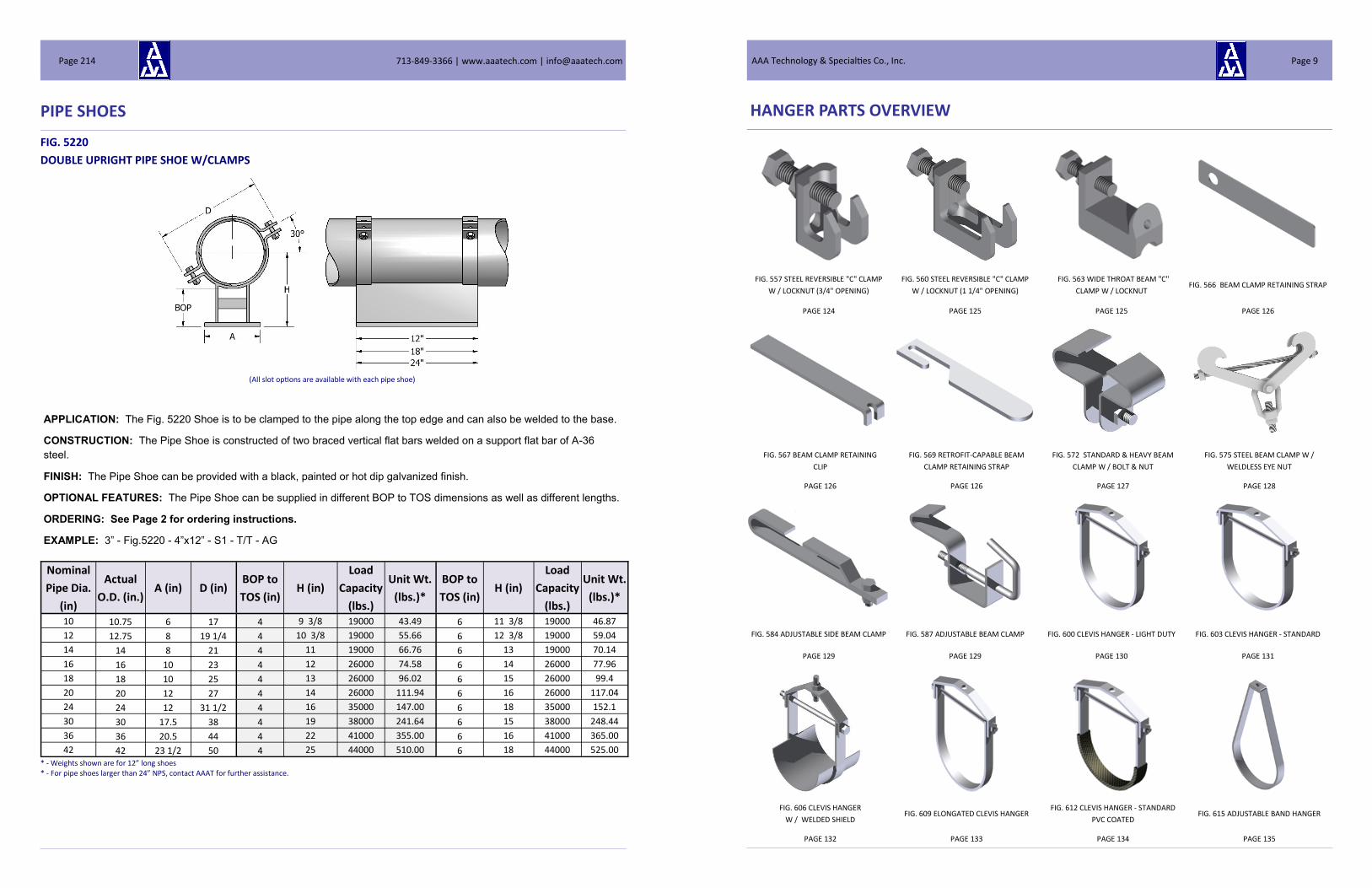
FIG. 5220
DOUBLE UPRIGHT PIPE SHOE W/CLAMPS
* - Weights shown are for 12” long shoes
Nominal
Pipe Dia.
(in)
Actual
O.D. (in.) A (in) D (in)
BOP to
TOS (in) H (in)
Load
Capacity
(lbs.)
Unit Wt.
(lbs.)*
BOP to
TOS (in) H (in)
Load
Capacity
(lbs.)
Unit Wt.
(lbs.)*
10 10.75 6 17 4 9 3/8 19000 43.49 6 11 3/8 19000 46.87
12 12.75 8 19 1/4 4 10 3/8 19000 55.66 6 12 3/8 19000 59.04
14 14 8 21 4 11 19000 66.76 6 13 19000 70.14
16 16 10 23 4 12 26000 74.58 6 14 26000 77.96
18 18 10 25 4 13 26000 96.02 6 15 26000 99.4
20 20 12 27 4 14 26000 111.94 6 16 26000 117.04
24 24 12 31 1/2 4 16 35000 147.00 6 18 35000 152.1
30 30 17.5 38 4 19 38000 241.64 6 15 38000 248.44
36 36 20.5 44 4 22 41000 355.00 6 16 41000 365.00
42 42 23 1/2 50 4 25 44000 510.00 6 18 44000 525.00
APPLICATION: The Fig. 5220 Shoe is to be clamped to the pipe along the top edge and can also be welded to the base.
CONSTRUCTION: The Pipe Shoe is constructed of two braced vertical flat bars welded on a support flat bar of A-36
steel.
FINISH: The Pipe Shoe can be provided with a black, painted or hot dip galvanized finish.
OPTIONAL FEATURES: The Pipe Shoe can be supplied in different BOP to TOS dimensions as well as different lengths.
ORDERING: See Page 2 for ordering instructions.
EXAMPLE: 3” - Fig.5220 - 4”x12” - S1 - T/T - AG
* - For pipe shoes larger than 24” NPS, contact AAAT for further assistance.
(All slot options are available with each pipe shoe)
713-849-3366 | www.aaatech.com | [email protected] Page 214 AAA Technology & Specialties Co., Inc. Page 9
HANGER PARTS OVERVIEW
FIG. 557 STEEL REVERSIBLE "C" CLAMP
W / LOCKNUT (3/4" OPENING)
FIG. 560 STEEL REVERSIBLE "C" CLAMP
W / LOCKNUT (1 1/4" OPENING)
FIG. 563 WIDE THROAT BEAM "C"
CLAMP W / LOCKNUT FIG. 566 BEAM CLAMP RETAINING STRAP
PAGE 124 PAGE 125 PAGE 125 PAGE 126
FIG. 567 BEAM CLAMP RETAINING
CLIP
FIG. 569 RETROFIT-CAPABLE BEAM
CLAMP RETAINING STRAP
FIG. 572 STANDARD & HEAVY BEAM
CLAMP W / BOLT & NUT
FIG. 575 STEEL BEAM CLAMP W /
WELDLESS EYE NUT
PAGE 126 PAGE 126 PAGE 127 PAGE 128
FIG. 584 ADJUSTABLE SIDE BEAM CLAMP FIG. 587 ADJUSTABLE BEAM CLAMP FIG. 600 CLEVIS HANGER - LIGHT DUTY FIG. 603 CLEVIS HANGER - STANDARD
PAGE 129 PAGE 129 PAGE 130 PAGE 131
FIG. 606 CLEVIS HANGER
W / WELDED SHIELD FIG. 609 ELONGATED CLEVIS HANGER
FIG. 612 CLEVIS HANGER - STANDARD
PVC COATED FIG. 615 ADJUSTABLE BAND HANGER
PAGE 132 PAGE 133 PAGE 134 PAGE 135

713-849-3366 | www.aaatech.com | [email protected] Page 10
HANGER PARTS OVERVIEW
FIG. 618 ADJUSTABLE BAND HANGER
W / SWIVEL NUT
FIG. 621 PVC COATED ADJUSTABLE BAND
HANGER W / SWIVEL NUT
FIG. 624 J-HANGER FOR PIPE OR
CONDUIT
FIG. 627 PVC COATED J-HANGER FOR
PIPE OR CONDUIT
PAGE 136 PAGE 137 PAGE 138 PAGE 139
FIG. 639 STRAIGHT J-HOOK FIG. 642 OFFSET J-HOOK FIG. 645 STANDARD PIPE STRAP FIG. 648 FLUSH MOUNT PIPE STRAP
PAGE 140 PAGE 140 PAGE 141 PAGE 141
FIG. 700 STANDARD U-BOLT FIG. 703 LIGHT DUTY U-BOLT FIG. 706 HEAVY DUTY U-BOLT FIG. 712 STANDARD 2-BOLT PIPE CLAMP
PAGE 142 PAGE 143 PAGE 144 PAGE 145
FIG. 715 INTERMEDIATE 2-BOLT PIPE
CLAMP FIG. 718 HEAVY 2-BOLT PIPE CLAMP
FIG. 721 EXTRA HEAVY 2-BOLT PIPE
CLAMP FIG. 724 STANDARD 3-BOLT PIPE CLAMP
PAGE 146 PAGE 147 PAGE 148 PAGE 149
PIPE SHOES
FIG. 5210
DOUBLE UPRIGHT PIPE SHOE W/U-BOLTS
* - Weights shown are for 12” long shoes
Nominal
Pipe Dia.
(in)
Actual
O.D. (in.) A (in) D (in)
BOP to
TOS (in) H (in)
Load
Capacity
(lbs.)
Unit Wt.
(lbs.)*
BOP to
TOS (in) H (in)
Load
Capacity
(lbs.)
Unit Wt.
(lbs.)*
10 10.75 6 14 4 9 3/8 19000 19.77 6 11 3/8 19000 23.15
12 12.75 8 16.75 4 10 3/8 19000 33.18 6 12 3/8 19000 36.56
14 14 8 18 4 11 19000 36.98 6 13 19000 40.36
16 16 10 19.75 4 12 26000 42.18 6 14 26000 45.56
18 18 10 22 4 13 26000 50.78 6 15 26000 54.16
20 20 12 24 4 14 26000 59.76 6 16 26000 64.86
24 24 12 28 4 16 35000 64.36 6 18 35000 69.46
30 30 17 1/2 34 4 19 38000 88.96 6 15 38000 95.76
36 36 20 1/2 40 4 22 41000 112.46 6 16 41000 119.26
42 42 23 1/2 46 4 25 44000 129.57 6 18 44000 136.37
APPLICATION: The Fig. 5210 Shoe is to be clamped to the pipe along the top edge and can also be welded to the base.
CONSTRUCTION: The Pipe Shoe is constructed of two braced vertical flat bars welded on a support flat bar of A-36
steel.
FINISH: The Pipe Shoe can be provided with a black, painted or hot dip galvanized finish.
OPTIONAL FEATURES: The Pipe Shoe can be supplied in different BOP to TOS dimensions as well as different lengths.
ORDERING: See Page 2 for ordering instructions.
EXAMPLE: 3” - Fig. 5210 - 4”x12” - S1 - T/T - AG
* - For pipe shoes larger than 24” NPS, contact AAAT for further assistance.
(All slot options are available with each pipe shoe)
AAA Technology & Specialties Co., Inc. Page 213

PIPE SHOES
FIG. 5200
DOUBLE UPRIGHT PIPE SHOE
* - Weights shown are for 12” long shoes
Nominal
Pipe Dia.
(in)
Actual
O.D. (in.) A (in)
BOP to
TOS (in) H (in)
Load
Capacity
(lbs.)
Unit Wt.
(lbs.)*
BOP to
TOS (in) H (in)
Load
Capacity
(lbs.)
Unit Wt.
(lbs.)*
10 10.75 6 4 9 3/8 19000 11.89 6 11 3/8 19000 15.27
12 12.75 8 4 10 3/8 19000 20.38 6 12 3/8 19000 23.76
14 14 8 4 11 19000 20.38 6 13 19000 23.76
16 16 10 4 12 26000 23.78 6 14 26000 27.16
18 18 10 4 13 26000 23.78 6 15 26000 27.16
20 20 12 4 14 26000 30.56 6 16 26000 35.66
24 24 12 4 16 35000 30.56 6 18 35000 35.66
30 30 17 1/2 4 19 38000 43.36 6 15 38000 50.16
36 36 20 1/2 4 22 41000 48.46 6 16 41000 55.26
42 42 23 1/2 4 25 44000 53.57 6 18 44000 60.37
APPLICATION: The Fig. 5200 Shoe is to be welded to the pipe along the two top edges and can also be welded to the
base.
CONSTRUCTION: The Pipe Shoe is constructed of two braced vertical flat bars welded on a support flat bar of A-36
steel.
FINISH: The Pipe Shoe can be provided with a black, painted or hot dip galvanized finish.
OPTIONAL FEATURES: The Pipe Shoe can be supplied in different BOP to TOS dimensions as well as different lengths.
ORDERING: See Page 2 for ordering instructions.
EXAMPLE: 3” - Fig. 5200 - 4”x12” - S1 - T/T - AG
* - For pipe shoes larger than 24” NPS, contact AAAT for further assistance.
(All slot options are available with each pipe shoe)
713-849-3366 | www.aaatech.com | [email protected] Page 212 AAA Technology & Specialties Co., Inc. Page 11
HANGER PARTS OVERVIEW
FIG. 727 INTERMEDIATE 3-BOLT PIPE FIG. 733 HEAVY 3-BOLT PIPE CLAMP FIG. 733 EXTRA HEAVY 3-BOLT PIPE FIG. 736 STANDARD 3-BOLT ALLOY
PAGE 150 PAGE 151 PAGE 152 PAGE 153
FIG. 739 INTERMEDIATE 3-BOLT ALLOY
PIPE CLAMP
FIG. 748 STANDARD ALLOY YOKE
PIPE CLAMP FIG. 751 HEAVY ALLOY YOKE PIPE CLAMP FIG.754 EXTENSION PIPE OR RISER CLAMP
PAGE 154 PAGE 155 PAGE 156 PAGE 157
FIG. 763 OFFSET PIPE CLAMP FIG. 766 EXTENDED PIPE CLAMP FIG. 800 INSULATION PROTECTION
SHIELD
FIG. 803 RIBBED INSULATION
PROTECTION SHIELD
PAGE 158 PAGE 159 PAGE 160 PAGE 161
FIG. 806 CONTOURED CAST IRON PIPE
ROLLER FIG. 809 CLEVIS ROLLER HANGER FIG. 812 TWO ROD ROLLER TYPE HANGER FIG. 815 ADJUSTABLE SUPPORT ROLLER
PAGE 161 PAGE 162 PAGE 163 PAGE 164
713-849-3366 | www.aaatech.com | [email protected] Page 12
HANGER PARTS OVERVIEW
FIG. 818 ALTERNATE ADJUSTABLE
SUPPORT ROLLER FIG. 821 PIPE ROLLER CHAIR FIG. 824 CAST IRON PIPE ROLL FIG. 827 PIPE ROLLER & STAND
PAGE 165 PAGE 166 PAGE 167 PAGE 168
FIG. 830 ADJUSTABLE PIPE ROLLER &
STAND
FIG. 833 LARGE DIAMETER PIPE ROLLER
SUPPORT STAND
FIGS. 830, 842, 845 ,848, 851, 854, 857
PIPE COVERING PROTECTION SADDLE
1" TO 3" THK. INSULATION
FIG. 860 PIPE SADDLE
PAGE 169 PAGE 170 PAGE 171-173 PAGE 174
FIG. 863 PIPE SADDLE W/ U-BOLT FIG. 866 ADJUSTABLE PIPE SADDLE
SUPPORT FIG. 869 THREADED PIPE STAND
FIG. 900 CONCRETE INSERT PLATE FOR
ANCHOR BOLT
PAGE 175 PAGE 176 PAGE 177 PAGE 178
FIG. 903 CONCRETE INSERT FRAME FOR
ANCHOR BOLT FIG. 909 STEEL SPOT INSERT NUT
FIG. 912 CB-UNIVERSAL CONCRETE
INSERT
FIG. 915 CB-UNIVERSAL CONCRETE
INSERT NUT
PAGE 178 PAGE 179 PAGE 179 PAGE 180
PIPE SHOES
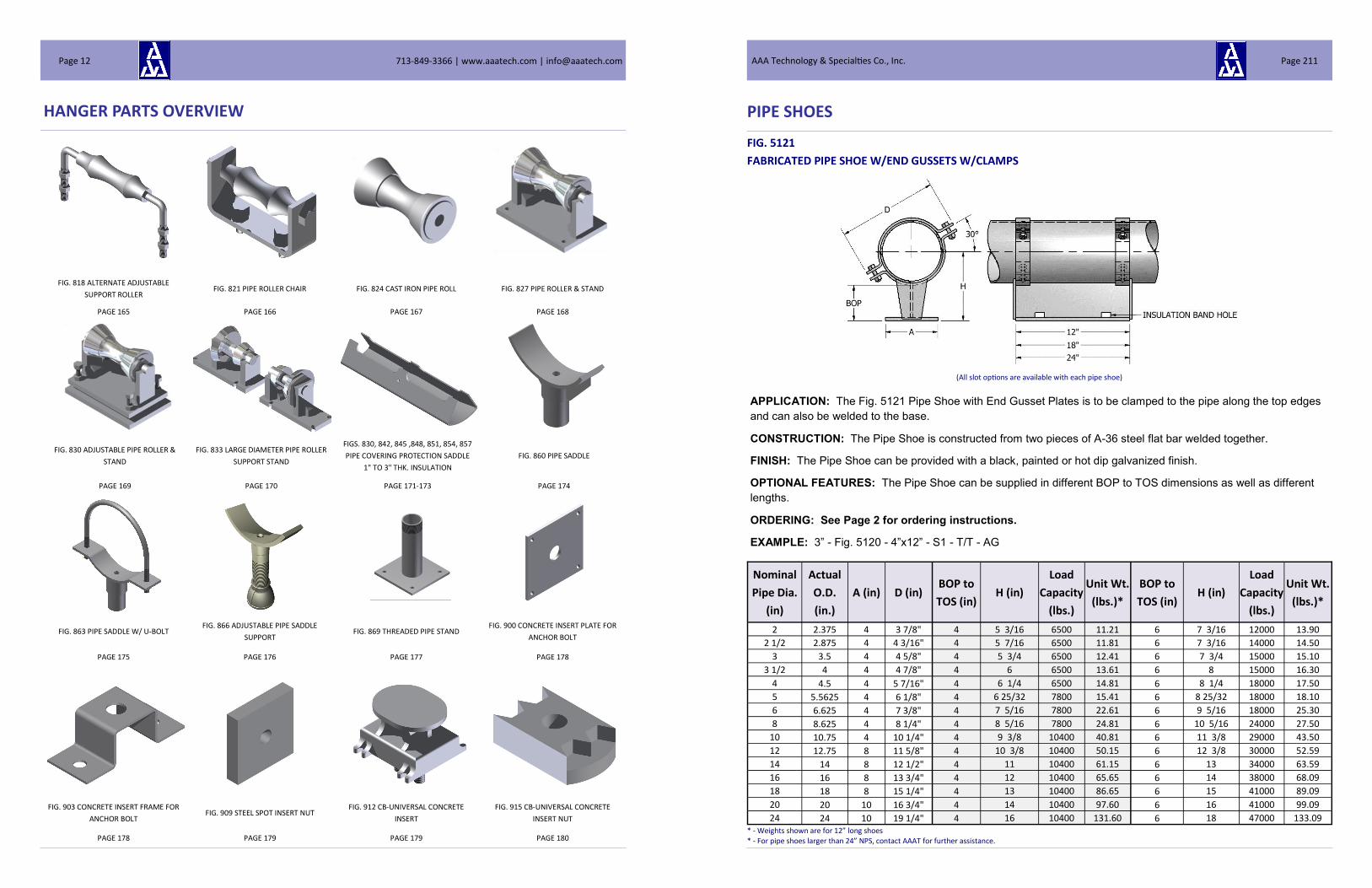
FIG. 5121
FABRICATED PIPE SHOE W/END GUSSETS W/CLAMPS
* - Weights shown are for 12” long shoes
Nominal
Pipe Dia.
(in)
Actual
O.D.
(in.)
A (in) D (in) BOP to
TOS (in) H (in)
Load
Capacity
(lbs.)
Unit Wt.
(lbs.)*
BOP to
TOS (in) H (in)
Load
Capacity
(lbs.)
Unit Wt.
(lbs.)*
2 2.375 4 3 7/8" 4 5 3/16 6500 11.21 6 7 3/16 12000 13.90
2 1/2 2.875 4 4 3/16" 4 5 7/16 6500 11.81 6 7 3/16 14000 14.50
3 3.5 4 4 5/8" 4 5 3/4 6500 12.41 6 7 3/4 15000 15.10
3 1/2 4 4 4 7/8" 4 6 6500 13.61 6 8 15000 16.30
4 4.5 4 5 7/16" 4 6 1/4 6500 14.81 6 8 1/4 18000 17.50
5 5.5625 4 6 1/8" 4 6 25/32 7800 15.41 6 8 25/32 18000 18.10
6 6.625 4 7 3/8" 4 7 5/16 7800 22.61 6 9 5/16 18000 25.30
8 8.625 4 8 1/4" 4 8 5/16 7800 24.81 6 10 5/16 24000 27.50
10 10.75 4 10 1/4" 4 9 3/8 10400 40.81 6 11 3/8 29000 43.50
12 12.75 8 11 5/8" 4 10 3/8 10400 50.15 6 12 3/8 30000 52.59
14 14 8 12 1/2" 4 11 10400 61.15 6 13 34000 63.59
16 16 8 13 3/4" 4 12 10400 65.65 6 14 38000 68.09
18 18 8 15 1/4" 4 13 10400 86.65 6 15 41000 89.09
20 20 10 16 3/4" 4 14 10400 97.60 6 16 41000 99.09
24 24 10 19 1/4" 4 16 10400 131.60 6 18 47000 133.09
APPLICATION: The Fig. 5121 Pipe Shoe with End Gusset Plates is to be clamped to the pipe along the top edges
and can also be welded to the base.
CONSTRUCTION: The Pipe Shoe is constructed from two pieces of A-36 steel flat bar welded together.
FINISH: The Pipe Shoe can be provided with a black, painted or hot dip galvanized finish.
OPTIONAL FEATURES: The Pipe Shoe can be supplied in different BOP to TOS dimensions as well as different
lengths.
ORDERING: See Page 2 for ordering instructions.
EXAMPLE: 3” - Fig. 5120 - 4”x12” - S1 - T/T - AG
* - For pipe shoes larger than 24” NPS, contact AAAT for further assistance.
(All slot options are available with each pipe shoe)
AAA Technology & Specialties Co., Inc. Page 211
PIPE SHOES
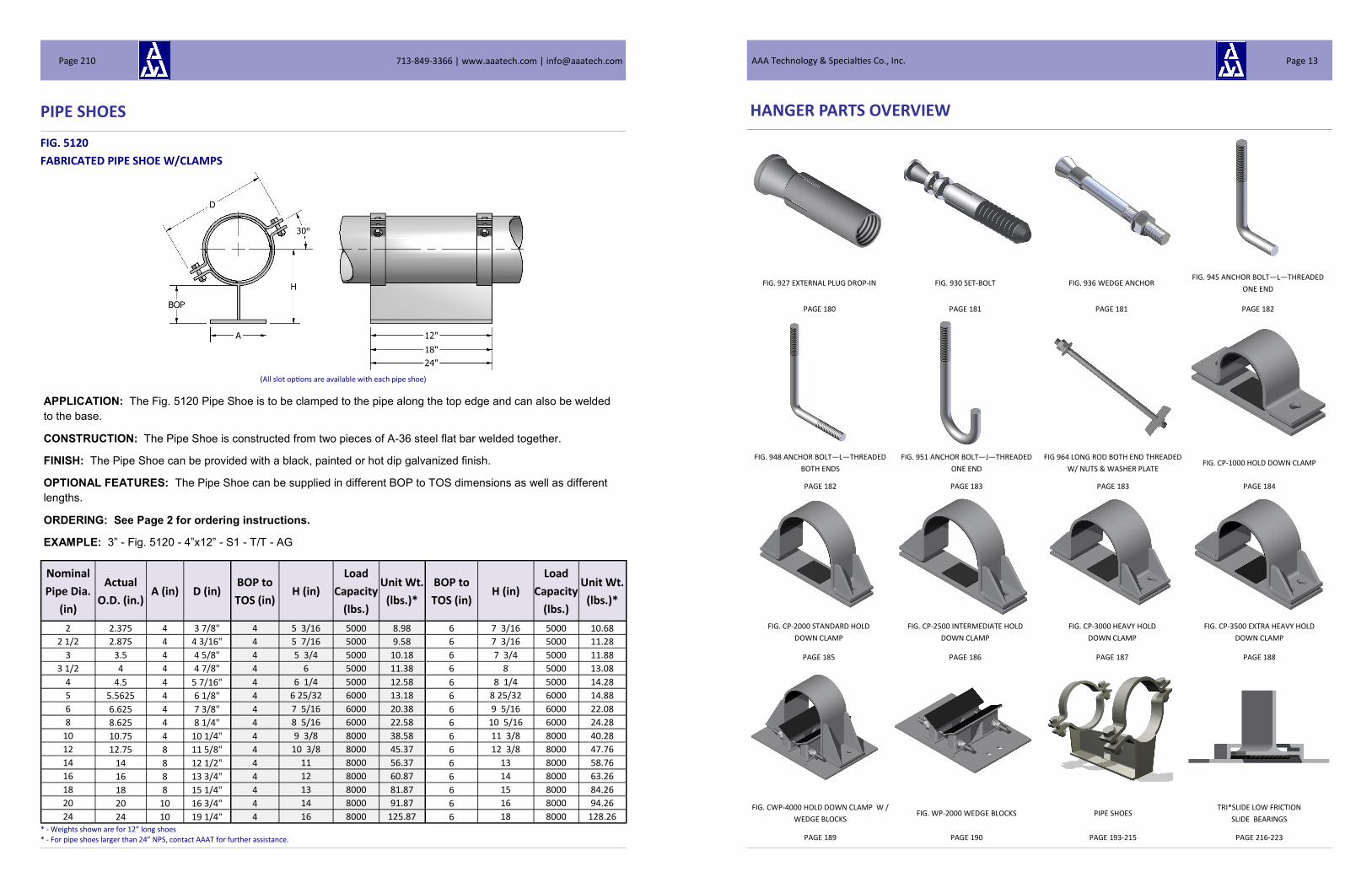
FIG. 5120
FABRICATED PIPE SHOE W/CLAMPS
* - Weights shown are for 12” long shoes
APPLICATION: The Fig. 5120 Pipe Shoe is to be clamped to the pipe along the top edge and can also be welded
to the base.
CONSTRUCTION: The Pipe Shoe is constructed from two pieces of A-36 steel flat bar welded together.
FINISH: The Pipe Shoe can be provided with a black, painted or hot dip galvanized finish.
OPTIONAL FEATURES: The Pipe Shoe can be supplied in different BOP to TOS dimensions as well as different
lengths.
ORDERING: See Page 2 for ordering instructions.
EXAMPLE: 3” - Fig. 5120 - 4”x12” - S1 - T/T - AG
Nominal
Pipe Dia.
(in)
Actual
O.D. (in.) A (in) D (in)
BOP to
TOS (in) H (in)
Load
Capacity
(lbs.)
Unit Wt.
(lbs.)*
BOP to
TOS (in) H (in)
Load
Capacity
(lbs.)
Unit Wt.
(lbs.)*
2 2.375 4 3 7/8" 4 5 3/16 5000 8.98 6 7 3/16 5000 10.68
2 1/2 2.875 4 4 3/16" 4 5 7/16 5000 9.58 6 7 3/16 5000 11.28
3 3.5 4 4 5/8" 4 5 3/4 5000 10.18 6 7 3/4 5000 11.88
3 1/2 4 4 4 7/8" 4 6 5000 11.38 6 8 5000 13.08
4 4.5 4 5 7/16" 4 6 1/4 5000 12.58 6 8 1/4 5000 14.28
5 5.5625 4 6 1/8" 4 6 25/32 6000 13.18 6 8 25/32 6000 14.88
6 6.625 4 7 3/8" 4 7 5/16 6000 20.38 6 9 5/16 6000 22.08
8 8.625 4 8 1/4" 4 8 5/16 6000 22.58 6 10 5/16 6000 24.28
10 10.75 4 10 1/4" 4 9 3/8 8000 38.58 6 11 3/8 8000 40.28
12 12.75 8 11 5/8" 4 10 3/8 8000 45.37 6 12 3/8 8000 47.76
14 14 8 12 1/2" 4 11 8000 56.37 6 13 8000 58.76
16 16 8 13 3/4" 4 12 8000 60.87 6 14 8000 63.26
18 18 8 15 1/4" 4 13 8000 81.87 6 15 8000 84.26
20 20 10 16 3/4" 4 14 8000 91.87 6 16 8000 94.26
24 24 10 19 1/4" 4 16 8000 125.87 6 18 8000 128.26
* - For pipe shoes larger than 24” NPS, contact AAAT for further assistance.
(All slot options are available with each pipe shoe)
713-849-3366 | www.aaatech.com | [email protected] Page 210 AAA Technology & Specialties Co., Inc. Page 13
HANGER PARTS OVERVIEW
FIG. 927 EXTERNAL PLUG DROP-IN FIG. 930 SET-BOLT FIG. 936 WEDGE ANCHOR FIG. 945 ANCHOR BOLT—L—THREADED
ONE END
PAGE 180 PAGE 181 PAGE 181 PAGE 182
FIG. 948 ANCHOR BOLT—L—THREADED
BOTH ENDS
FIG. 951 ANCHOR BOLT—J—THREADED
ONE END
FIG 964 LONG ROD BOTH END THREADED
W/ NUTS & WASHER PLATE FIG. CP-1000 HOLD DOWN CLAMP
PAGE 182 PAGE 183 PAGE 183 PAGE 184
FIG. CP-2000 STANDARD HOLD
DOWN CLAMP
FIG. CP-2500 INTERMEDIATE HOLD
DOWN CLAMP
FIG. CP-3000 HEAVY HOLD
DOWN CLAMP
FIG. CP-3500 EXTRA HEAVY HOLD
DOWN CLAMP
PAGE 185 PAGE 186 PAGE 187 PAGE 188
FIG. CWP-4000 HOLD DOWN CLAMP W /
WEDGE BLOCKS FIG. WP-2000 WEDGE BLOCKS PIPE SHOES
TRI*SLIDE LOW FRICTION
SLIDE BEARINGS
PAGE 189 PAGE 190 PAGE 193-215 PAGE 216-223

713-849-3366 | www.aaatech.com | [email protected] Page 14
HANGER PARTS OVERVIEW
TRI*WEAR™ FRP WEAR PADS TRI*COMPOSITE™ MOLDED INSULATED
SUPPORTS
TRI*GUARD™ DURABLE
THERMOPLASTIC SUPPORTS
PAGE 224 PAGE 225-226 PAGE 227
PIPE SHOES
FIG. 5111
FABRICATED PIPE SHOE W/END GUSSETS w/U-BOLTS
* - Weights shown are for 12” long shoes
APPLICATION: The Fig. 5111 Pipe Shoe with End Gusset Plates is to be clamped to the pipe along the top edges
and can also be welded to the base.
CONSTRUCTION: The Pipe Shoe is constructed from two pieces of A-36 steel flat bar welded together.
FINISH: The Pipe Shoe can be provided with a black, painted or hot dip galvanized finish.
OPTIONAL FEATURES: The Pipe Shoe can be supplied in different BOP to TOS dimensions as well as different
lengths.
ORDERING: See Page 2 for ordering instructions.
EXAMPLE: 3” - Fig. 5110 - 4”x12” - S1 - T/T - AG
Nominal
Pipe Dia.
(in)
Actual
O.D.
(in.)
A (in) D (in) BOP to
TOS (in) H (in)
Load
Capacity
(lbs.)
Unit Wt.
(lbs.)*
BOP to
TOS (in) H (in)
Load
Capacity
(lbs.)
Unit Wt.
(lbs.)*
2 2.375 4 3 7/8" 4 5 3/16 6500 10.25 6 7 3/16 6500 12.94
2 1/2 2.875 4 4 3/16" 4 5 7/16 6500 10.61 6 7 3/16 6500 13.30
3 3.5 4 4 5/8" 4 5 3/4 6500 10.97 6 7 3/4 6500 13.66
3 1/2 4 4 4 7/8" 4 6 6500 11.69 6 8 6500 14.38
4 4.5 4 5 7/16" 4 6 1/4 6500 12.41 6 8 1/4 6500 15.10
5 5.5625 4 6 1/8" 4 6 25/32 7800 12.77 6 8 25/32 7800 15.46
6 6.625 4 7 3/8" 4 7 5/16 7800 17.09 6 9 5/16 7800 19.78
8 8.625 4 8 1/4" 4 8 5/16 7800 18.41 6 10 5/16 7800 21.10
10 10.75 4 10 1/4" 4 9 3/8 10400 28.01 6 11 3/8 10400 30.70
12 12.75 8 11 5/8" 4 10 3/8 10400 35.95 6 12 3/8 10400 38.39
14 14 8 12 1/2" 4 11 10400 42.55 6 13 10400 44.99
16 16 8 13 3/4" 4 12 10400 45.25 6 14 10400 47.69
18 18 8 15 1/4" 4 13 10400 57.85 6 15 10400 60.29
20 20 10 16 3/4" 4 14 10400 64.80 6 16 10400 66.29
24 24 10 19 1/4" 4 16 10400 85.20 6 18 10400 86.69
* - For pipe shoes larger than 24” NPS, contact AAAT for further assistance.
(All slot options are available with each pipe shoe)
AAA Technology & Specialties Co., Inc. Page 209

PIPE SHOES
FIG. 5110
FABRICATED PIPE SHOE w/U-BOLTS
* - Weights shown are for 12” long shoes
Nominal
Pipe Dia.
(in)
Actual
O.D. (in.) A (in) D (in)
BOP to
TOS (in) H (in)
Load
Capacity
(lbs.)
Unit Wt.
(lbs.)*
BOP to
TOS (in) H (in)
Load
Capacity
(lbs.)
Unit Wt.
(lbs.)*
2 2.375 4 3 7/8" 4 5 3/16 5000 8.02 6 7 3/16 5000 9.72
2 1/2 2.875 4 4 3/16" 4 5 7/16 5000 8.29 6 7 3/16 5000 10.08
3 3.5 4 4 5/8" 4 5 3/4 5000 8.74 6 7 3/4 5000 10.44
3 1/2 4 4 4 7/8" 4 6 5000 9.46 6 8 5000 11.16
4 4.5 4 5 7/16" 4 6 1/4 5000 10.18 6 8 1/4 5000 11.88
5 5.5625 4 6 1/8" 4 6 25/32 5000 10.54 6 8 25/32 5000 12.24
6 6.625 4 7 3/8" 4 7 5/16 6000 14.86 6 9 5/16 6000 16.56
8 8.625 4 8 1/4" 4 8 5/16 6000 16.18 6 10 5/16 6000 17.88
10 10.75 4 10 1/4" 4 9 3/8 6000 25.78 6 11 3/8 6000 27.48
12 12.75 8 11 5/8" 4 10 3/8 8000 31.17 6 12 3/8 8000 33.56
14 14 8 12 1/2" 4 11 8000 37.77 6 13 8000 40.16
16 16 8 13 3/4" 4 12 8000 40.47 6 14 8000 42.86
18 18 8 15 1/4" 4 13 8000 53.07 6 15 8000 55.46
20 20 10 16 3/4" 4 14 8000 59.07 6 16 8000 61.46
24 24 10 19 1/4" 4 16 8000 79.47 6 18 8000 81.86
APPLICATION: The Fig. 5110 Pipe Shoe is to be clamped to the pipe along the top edge and can also be welded to
the base.
CONSTRUCTION: The Pipe Shoe is constructed from two pieces of A-36 steel flat bar welded together.
FINISH: The Pipe Shoe can be provided with a black, painted or hot dip galvanized finish.
OPTIONAL FEATURES: The Pipe Shoe can be supplied in different BOP to TOS dimensions as well as different
lengths.
ORDERING: See Page 2 for ordering instructions.
EXAMPLE: 3” - Fig. 5110 - 4”x12” - S1 - T/T - AG
* - For pipe shoes larger than 24” NPS, contact AAAT for further assistance.
(All slot options are available with each pipe shoe)
713-849-3366 | www.aaatech.com | [email protected] Page 208
VARIABLE SPRING HANGERS
EQUAL™ VARIABLE SPRING HANGER GENERAL INFORMATION
WHEN SHOULD SPRING HANGERS BE USED?
Spring hangers should be used when: When pipe at a support location moves up off a rigid support & when it is necessary for support loading to be maintained When pipe at a support location needs to move downward to relieve load on equipment or stresses in the piping system When loads on attached equipment nozzles are limited and a spring hanger would assist in controlling the nozzle loading In other words, spring hangers are used to carry the dead weight of the piping system at a given support while allowing move-ment resulting from thermal expansion or contraction of the piping system. Spring hangers are frequently used at the first pipe support location adjacent to rotating equipment such as turbines, compressors, pumps or expander-compressors. At the-se support locations, the amount of vertical piping movement is typically small. However to enable the loading on the equip-ment to be controlled, a spring hanger is used to apply a support load on the pipe. In all instanced where the use of spring hangers is contemplated, evaluate the alternatives considering factors such as loading on equipment, cost, ease of installation and ease of operation. If spring hangers are the most economical and most satisfactorily solution, then by all means use them.
DESIGN FEATURES
Hanger casings are made of pipe for long life and durability. Spring coils are pre-compressed into the hanger casings reducing the overall casing length and insuring that support loads
can be obtained by making only a small adjustment. The finishes available for hanger casings are primed, painted or hot dipped galvanized. For extremely corrosive service
conditions, SermaGard® coatings are offered. These finish options provide our customers with a full range of choices. Mechanically closed units allow AAA Technology to stock components from which hangers can be easily and quickly as-
sembled for your hanger requirements. Mechanically closed units allow AAA Technology to insure that all components are properly finished and that no welding is required after the finishes are applied.
SPECIFICATIONS
AAA Technology's "EQUAL" brand variable spring supports are designed to meet the requirements of the Manufacturers Standardization Society's MSS SP-58 "Hangers and Supports—Selection and Application" as well as the ASME Codes for Pres-sure Piping. Spring hanger casings to be utilized in corrosive environments are galvanized in accordance with ASTM Specifica-tion A-153 unless the customer opts for the SermaGard® coating.
LOAD SCALE PLATE
A Load Scale Plate is attached to each "EQUAL" variable spring hanger casing directly adjacent to the slot in the casing. The Load Scale Plate contains information such as hanger size, type, figure number, customer Identification tag number, the spring rate, the installed load and the operating load. Installed and Operating position tags are permanently attached to the hanger casings on the Load Scale Plate. The position tags enable field personnel to easily view the position of the bottom of the com-pression plate in the hanger casing at anytime therefore enabling the field personnel immediately define the position of the pipe in the travel range. The travel scale is given in both Imperial and SI units enabling use anywhere in the world. The Load Scale Plates are made of 20 gauge stainless steel and are attached to the spring hanger casings with stainless steel rivets. PRESET PIECES
When customers order variable spring hangers, the installed load is specified. AAA Technology is required to supply the spring hanger preset to the installed position. In such instances, the spring hanger loading will be set in our shop to the customer specified installed load and a preset piece will be placed between to top plate and the compression plate so that the installed load will be maintained. Preset pieces are to be removed after the spring hanger has been installed and the piping system is ready for operation.
AAA Technology & Specialties Co., Inc. Page 15

VARIABLE SPRING HANGERS
TRAVEL STOPS
Travel stop are furnished only upon request. Full travel stops limiting both upward and downward movement may be supplied; or upward or downward travel stops individually may be supplied. Full travel stops effectively convert the hanger assembly to a rigid support until the stops are removed. Upward travel stops restrict upward movement beyond a customer specified point on the travel scale. Downward travel stops restrict downward movement beyond a customer specified point on the trav-el scale and are frequently employed during erection and hydrostatic testing. A red tag is attached to each travel stop to em-phasize the need to remove the travel stops before the piping system is placed in service.
LIFTING LUGS
Upon customer request, lifting lugs may be welded to the hanger casings of designated spring hanger in order to provide a sure means of attachment for lifting during installation. Contact AAA Technology for details.
FIELD ADJUSTMENT
Once the piping and the spring hangers are installed and hydro- tested, the preset bar should be removed from the spring hanger. The compression plate on top of the spring coil should be at the installed load mark on the spring hanger load scale. If the bottom of the compression plate is not at the installed load mark on the spring hanger load scale, then the load should be adjusted so that it is. After the piping system is placed in service, the compres-sion plate should indicate that the load being carried is the designated operating load. If the bottom of the compression plate is not at the operating load mark on the spring hanger load scale, then the load should be adjusted so that the bottom of the compression plate is at the operating load position. To adjust the load carried by the spring hangers types "A", "B", "C", "E", and "G", turn the turnbuckle clockwise or counter clockwise, as necessary, until the bottom of the compression plate lines up with the proper travel tag on the travel scale. For hanger type "D", loosen the lock nut and adjustment the heavy hex nut on top of the pipe stem which sits on the compression plate until the bottom of the compression plate lines up with the proper travel tag on the travel scale. For hanger type "F", turn the load column clockwise or counterclockwise, as necessary, until the bottom of the compression plate lines up with the proper travel tag on the travel scale.
DETERMINING THE HANGER TYPE
The type of variable spring hanger to be used for specific applications depends upon controlling factors such as the amount of head room available, whether the pipe is to be supported from above or from below, the configuration of the structural steel from which the pipe is to be supported, etc. Review the characteristics of the seven standard variable hanger types shown on the next page and select the type that best fits your requirements.
EQUAL™ SPRING HANGER GENERAL INFORMATION
713-849-3366 | www.aaatech.com | [email protected] Page 16
PIPE SHOES
FIG. 5101
FABRICATED PIPE SHOE W/ END GUSSETS
* - Weights shown are for 12” long shoes
Nominal
Pipe Dia.
(in)
Actual
O.D. (in.) A (in)
BOP to
TOS (in) H (in)
Load
Capacity
(lbs.)
Unit Wt.
(lbs.)*
BOP to
TOS (in) H (in)
Load
Capacity
(lbs.)
Unit Wt.
(lbs.)*
2 2.375 4 4 5 3/16 6500 8.81 6 7 3/16 6500 11.50
2 1/2 2.875 4 4 5 7/16 6500 8.81 6 7 3/16 6500 11.50
3 3.5 4 4 5 3/4 6500 8.81 6 7 3/4 6500 11.50
3 1/2 4 4 4 6 6500 8.81 6 8 6500 11.50
4 4.5 4 4 6 1/4 6500 8.81 6 8 1/4 6500 11.50
5 5.5625 4 4 6 25/32 7800 8.81 6 8 25/32 7800 11.50
6 6.625 4 4 7 5/16 7800 8.81 6 9 5/16 7800 11.50
8 8.625 4 4 8 5/16 7800 8.81 6 10 5/16 7800 11.50
10 10.75 4 4 9 3/8 10400 8.81 6 11 3/8 10400 11.50
12 12.75 8 4 10 3/8 10400 14.65 6 12 3/8 10400 17.09
14 14 8 4 11 10400 14.65 6 13 10400 17.09
16 16 8 4 12 10400 14.65 6 14 10400 17.09
18 18 8 4 13 10400 14.65 6 15 10400 17.09
20 20 10 4 14 10400 15.60 6 16 10400 17.09
24 24 10 4 16 10400 15.60 6 18 10400 17.09
APPLICATION: The Fig. 5101 Pipe Shoe with End Gusset Plates is to be welded to the pipe along the top edges
and can also be welded to the base.
CONSTRUCTION: The Pipe Shoe is constructed from two pieces of A-36 steel flat bar welded together.
FINISH: The Pipe Shoe can be provided with a black, painted or hot dip galvanized finish.
OPTIONAL FEATURES: The Pipe Shoe can be supplied in different BOP to TOS dimensions as well as different
lengths.
ORDERING: See beginning of this section for ordering instructions.
EXAMPLE: 3” - Fig.5101 - 4”x12” - S1 - T/T - AG
* - For pipe shoes larger than 24” NPS, contact AAAT for further assistance.
(All slot options are available with each pipe shoe)
AAA Technology & Specialties Co., Inc. Page 207
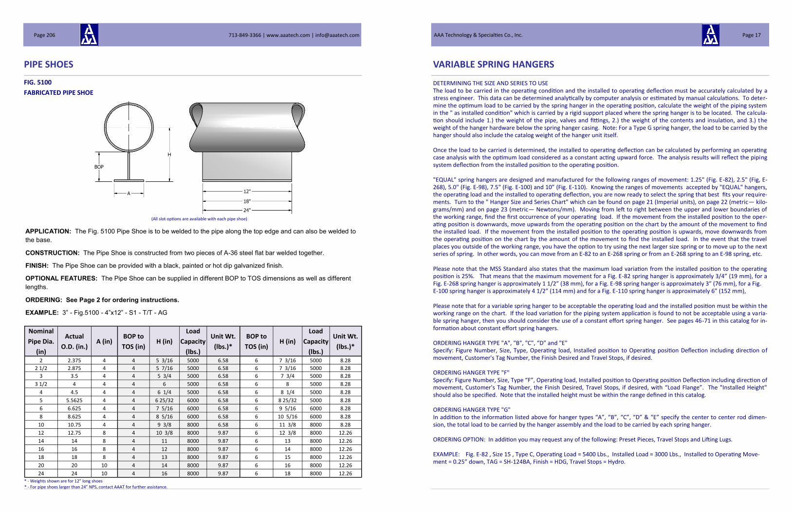
PIPE SHOES
FIG. 5100
FABRICATED PIPE SHOE
* - Weights shown are for 12” long shoes
APPLICATION: The Fig. 5100 Pipe Shoe is to be welded to the pipe along the top edge and can also be welded to
the base.
CONSTRUCTION: The Pipe Shoe is constructed from two pieces of A-36 steel flat bar welded together.
FINISH: The Pipe Shoe can be provided with a black, painted or hot dip galvanized finish.
OPTIONAL FEATURES: The Pipe Shoe can be supplied in different BOP to TOS dimensions as well as different
lengths.
ORDERING: See Page 2 for ordering instructions.
EXAMPLE: 3” - Fig.5100 - 4”x12” - S1 - T/T - AG
Nominal
Pipe Dia.
(in)
Actual
O.D. (in.) A (in)
BOP to
TOS (in) H (in)
Load
Capacity
(lbs.)
Unit Wt.
(lbs.)*
BOP to
TOS (in) H (in)
Load
Capacity
(lbs.)
Unit Wt.
(lbs.)*
2 2.375 4 4 5 3/16 5000 6.58 6 7 3/16 5000 8.28
2 1/2 2.875 4 4 5 7/16 5000 6.58 6 7 3/16 5000 8.28
3 3.5 4 4 5 3/4 5000 6.58 6 7 3/4 5000 8.28
3 1/2 4 4 4 6 5000 6.58 6 8 5000 8.28
4 4.5 4 4 6 1/4 5000 6.58 6 8 1/4 5000 8.28
5 5.5625 4 4 6 25/32 6000 6.58 6 8 25/32 5000 8.28
6 6.625 4 4 7 5/16 6000 6.58 6 9 5/16 6000 8.28
8 8.625 4 4 8 5/16 6000 6.58 6 10 5/16 6000 8.28
10 10.75 4 4 9 3/8 8000 6.58 6 11 3/8 8000 8.28
12 12.75 8 4 10 3/8 8000 9.87 6 12 3/8 8000 12.26
14 14 8 4 11 8000 9.87 6 13 8000 12.26
16 16 8 4 12 8000 9.87 6 14 8000 12.26
18 18 8 4 13 8000 9.87 6 15 8000 12.26
20 20 10 4 14 8000 9.87 6 16 8000 12.26
24 24 10 4 16 8000 9.87 6 18 8000 12.26
* - For pipe shoes larger than 24” NPS, contact AAAT for further assistance.
(All slot options are available with each pipe shoe)
713-849-3366 | www.aaatech.com | [email protected] Page 206
VARIABLE SPRING HANGERS
DETERMINING THE SIZE AND SERIES TO USE The load to be carried in the operating condition and the installed to operating deflection must be accurately calculated by a stress engineer. This data can be determined analytically by computer analysis or estimated by manual calculations. To deter-mine the optimum load to be carried by the spring hanger in the operating position, calculate the weight of the piping system in the " as installed condition" which is carried by a rigid support placed where the spring hanger is to be located. The calcula-tion should include 1.) the weight of the pipe, valves and fittings, 2.) the weight of the contents and insulation, and 3.) the weight of the hanger hardware below the spring hanger casing. Note: For a Type G spring hanger, the load to be carried by the hanger should also include the catalog weight of the hanger unit itself. Once the load to be carried is determined, the installed to operating deflection can be calculated by performing an operating case analysis with the optimum load considered as a constant acting upward force. The analysis results will reflect the piping system deflection from the installed position to the operating position. "EQUAL" spring hangers are designed and manufactured for the following ranges of movement: 1.25" (Fig. E-82), 2.5" (Fig, E-268), 5.0" (Fig. E-98), 7.5" (Fig. E-100) and 10” (Fig. E-110). Knowing the ranges of movements accepted by "EQUAL" hangers, the operating load and the installed to operating deflection, you are now ready to select the spring that best fits your require-ments. Turn to the " Hanger Size and Series Chart" which can be found on page 21 (Imperial units), on page 22 (metric— kilo-grams/mm) and on page 23 (metric— Newtons/mm). Moving from left to right between the upper and lower boundaries of the working range, find the first occurrence of your operating load. If the movement from the installed position to the oper-ating position is downwards, move upwards from the operating position on the chart by the amount of the movement to find the installed load. If the movement from the installed position to the operating position is upwards, move downwards from the operating position on the chart by the amount of the movement to find the installed load. In the event that the travel places you outside of the working range, you have the option to try using the next larger size spring or to move up to the next series of spring. In other words, you can move from an E-82 to an E-268 spring or from an E-268 spring to an E-98 spring, etc. Please note that the MSS Standard also states that the maximum load variation from the installed position to the operating position is 25%. That means that the maximum movement for a Fig. E-82 spring hanger is approximately 3/4” (19 mm), for a Fig. E-268 spring hanger is approximately 1 1/2” (38 mm), for a Fig. E-98 spring hanger is approximately 3” (76 mm), for a Fig. E-100 spring hanger is approximately 4 1/2” (114 mm) and for a Fig. E-110 spring hanger is approximately 6” (152 mm), Please note that for a variable spring hanger to be acceptable the operating load and the installed position must be within the working range on the chart. If the load variation for the piping system application is found to not be acceptable using a varia-ble spring hanger, then you should consider the use of a constant effort spring hanger. See pages 46-71 in this catalog for in-formation about constant effort spring hangers. ORDERING HANGER TYPE "A", "B", "C", “D” and "E" Specify: Figure Number, Size, Type, Operating load, Installed position to Operating position Deflection including direction of movement, Customer's Tag Number, the Finish Desired and Travel Stops, if desired. ORDERING HANGER TYPE "F" Specify: Figure Number, Size, Type “F”, Operating load, Installed position to Operating position Deflection including direction of movement, Customer's Tag Number, the Finish Desired, Travel Stops, if desired, with “Load Flange”. The "Installed Height" should also be specified. Note that the installed height must be within the range defined in this catalog. ORDERING HANGER TYPE "G" In addition to the information listed above for hanger types “A”, “B”, “C”, “D” & “E” specify the center to center rod dimen-sion, the total load to be carried by the hanger assembly and the load to be carried by each spring hanger. ORDERING OPTION: In addition you may request any of the following: Preset Pieces, Travel Stops and Lifting Lugs. EXAMPLE: Fig. E-82 , Size 15 , Type C, Operating Load = 5400 Lbs., Installed Load = 3000 Lbs., Installed to Operating Move-ment = 0.25” down, TAG = SH-124BA, Finish = HDG, Travel Stops = Hydro.
AAA Technology & Specialties Co., Inc. Page 17

APPLICATION DATA
TYPE A
Used where ample headroom is available and where it is desired to locate the spring hanger at a specific elevation. Structural attachment point is at a point above the top of the hanger.
VARIABLE SPRING HANGERS
TYPE B
Used where headroom is limited. Head attachment is a single lug. Typically used in conjunction with Fig. 515 beam bracket, a Fig. 415 steel clevis or back to back angles.
713-849-3366 | www.aaatech.com | [email protected] Page 18
PIPE SHOES
FIG. 5021
SPLIT BEAM PIPE SHOE W/END GUSSETS W/CLAMPS
* - Weights shown are for 12” long shoes
Nominal
Pipe Dia.
(in)
Actual
O.D.
(in.)
A (in) D (in) BOP to
TOS (in) H (in)
Load
Capacity
(lbs.)
Unit Wt.
(lbs.)*
BOP to
TOS (in) H (in)
Load
Capacity
(lbs.)
Unit
Wt.
(lbs.)* 2 2.375 4 3 7/8" 4 5 3/16 6500 11.13 6 7 3/16 6500 13.62
2 1/2 2.875 4 4 3/16" 4 5 7/16 6500 11.93 6 7 3/16 6500 14.22
3 3.5 4 4 5/8" 4 5 3/4 6500 12.33 6 7 3/4 6500 14.82
3 1/2 4 4 4 7/8" 4 6 6500 13.53 6 8 6500 16.02
4 4.5 4 5 7/16" 4 6 1/4 6500 14.73 6 8 1/4 6500 17.22
5 5.5625 4 6 1/8" 4 6 25/32 7800 15.33 6 8 25/32 7800 17.82
6 6.625 4 7 3/8" 4 7 5/16 7800 22.53 6 9 5/16 7800 25.02
8 8.625 4 8 1/4" 4 8 5/16 7800 24.73 6 10 5/16 7800 27.22
10 10.75 4 10 1/4" 4 9 3/8 10400 40.73 6 11 3/8 10400 43.22
12 12.75 6.5 11 5/8" 4 10 3/8 10400 52.28 6 12 3/8 10400 55.40
14 14 6.5 12 1/2" 4 11 10400 63.28 6 13 10400 66.40
16 16 6.5 13 3/4" 4 12 10400 67.78 6 14 10400 70.90
18 18 6.5 15 1/4" 4 13 10400 88.78 6 15 10400 91.90
20 20 8 16 3/4" 4 14 10400 103.23 6 16 10400 110.28
24 24 8 19 1/4" 4 16 10400 137.23 6 18 10400
APPLICATION: The Fig. 5021 Pipe Shoe with End Gusset Plates is to be clamped to the pipe along the top edges
and can also be welded to the base.
CONSTRUCTION: The Pipe Shoe is constructed from a split beam of A-36 steel.
FINISH: The Pipe Shoe can be provided with a black, painted or hot dip galvanized finish.
OPTIONAL FEATURES: The Pipe Shoe can be supplied in different BOP to TOS dimensions as well as different
lengths.
ORDERING: See beginning of this section for ordering instructions.
EXAMPLE: 3” - Fig.5020 - 4”x12” - S1 - T/T - AG
* - For pipe shoes larger than 24” NPS, contact AAAT for further assistance.
(All slot options are available with each pipe shoe)
AAA Technology & Specialties Co., Inc. Page 205

PIPE SHOES
FIG. 5020
SPLIT BEAM PIPE SHOE W/CLAMPS
* - Weights shown are for 12” long shoes
Nominal
Pipe Dia.
(in)
Actual
O.D. (in.) A (in) D (in)
BOP to
TOS (in) H (in)
Load
Capacity
(lbs.)
Unit Wt.
(lbs.)*
BOP to
TOS (in) H (in)
Load
Capacity
(lbs.)
Unit
Wt.
(lbs.)* 2 2.375 4 3 7/8" 4 5 3/16 5000 8.90 6 7 3/16 5000 10.40
2 1/2 2.875 4 4 3/16" 4 5 7/16 5000 9.50 6 7 3/16 5000 11.00
3 3.5 4 4 5/8" 4 5 3/4 5000 10.10 6 7 3/4 5000 11.60
3 1/2 4 4 4 7/8" 4 6 5000 11.30 6 8 5000 12.80
4 4.5 4 5 7/16" 4 6 1/4 5000 12.50 6 8 1/4 5000 14.00
5 5.5625 4 6 1/8" 4 6 25/32 6000 13.10 6 8 25/32 6000 14.60
6 6.625 4 7 3/8" 4 7 5/16 6000 20.30 6 9 5/16 6000 21.80
8 8.625 4 8 1/4" 4 8 5/16 6000 22.50 6 10 5/16 6000 24.00
10 10.75 4 10 1/4" 4 9 3/8 8000 38.50 6 11 3/8 8000 40.00
12 12.75 6.5 11 5/8" 4 10 3/8 8000 47.50 6 12 3/8 8000 48.50
14 14 6.5 12 1/2" 4 11 8000 58.50 6 13 8000 59.50
16 16 6.5 13 3/4" 4 12 8000 63.00 6 14 8000 64.00
18 18 6.5 15 1/4" 4 13 8000 84.00 6 15 8000 85.00
20 20 8 16 3/4" 4 14 8000 97.50 6 16 8000 102.00
24 24 8 19 1/4" 4 16 8000 131.50 6 18 8000 136.00
APPLICATION: The Fig. 5020 Pipe Shoe is to be clamped to the pipe along the top edge and can also be welded
to the base.
CONSTRUCTION: The Pipe Shoe is constructed from a split beam of A-36 steel.
FINISH: The Pipe Shoe can be provided with a black, painted or hot dip galvanized finish.
OPTIONAL FEATURES: The Pipe Shoe can be supplied in different BOP to TOS dimensions as well as different
lengths.
ORDERING: See beginning of this section for ordering instructions.
EXAMPLE: 3” - Fig.5020 - 4”x12” - S1 - T/T - AG
* - For pipe shoes larger than 24” NPS, contact AAAT for further assistance.
(All slot options are available with each pipe shoe)
713-849-3366 | www.aaatech.com | [email protected] Page 204
TYPE C
Used where headroom is limited. Head attachment is side-by-side lugs. Typically used in conjunction with a Fig. 418 weldless eye nut or a Fig. 521 structural welding lug.
TYPE D
Used where the spring hanger is mounted on top of a pair of back-to-back chan-nels. Provides for adjustment of the load by turning the nut at the top of rod
shown above.
TYPE E
Used where the spring hanger is mounted on top of a pair of back-to-back channels.
Provides for adjustments of the load from below the supporting channels by turning
the turnbuckle.
VARIABLE SPRING HANGERS
AAA Technology & Specialties Co., Inc. Page 19

TYPE F
Used where the spring hanger must be placed under the piping to provide support from the floor or a structural member. Typi-cally supplied with a load flange but can also be supplied with a roller.
TYPE G
Used where head room is insufficient to accommodate the spring hanger and the necessary associated hardware. Also used where an interference exists directly above the piping system at the support location. Note if the piping system being support-ed is not centered between the spring hangers each hanger will then carry its proportional load and will be different in magni-
tude.
VARIABLE SPRING HANGERS
713-849-3366 | www.aaatech.com | [email protected] Page 20
PIPE SHOES
Nominal
Pipe Dia.
(in)
Actual
O.D. (in.) A (in) D (in)
BOP to
TOS (in) H (in)
Load
Capacity
(lbs.)
Unit Wt.
(lbs.)*
BOP to
TOS (in) H (in)
Load
Capacity
(lbs.)
Unit
Wt.
(lbs.)* 2 2.375 4 3 7/8" 4 5 3/16 6500 11.13 6 7 3/16 6500 12.66
2 1/2 2.875 4 4 3/16" 4 5 7/16 6500 11.63 6 7 3/16 6500 13.02
3 3.5 4 4 5/8" 4 5 3/4 6500 12.33 6 7 3/4 6500 13.38
3 1/2 4 4 4 7/8" 4 6 6500 13.53 6 8 6500 14.10
4 4.5 4 5 7/16" 4 6 1/4 6500 14.73 6 8 1/4 6500 14.82
5 5.5625 4 6 1/8" 4 6 25/32 7800 15.33 6 8 25/32 7800 15.18
6 6.625 4 7 3/8" 4 7 5/16 7800 22.53 6 9 5/16 7800 19.50
8 8.625 4 8 1/4" 4 8 5/16 7800 24.73 6 10 5/16 7800 20.82
10 10.75 4 10 1/4" 4 9 3/8 10400 40.73 6 11 3/8 10400 30.42
12 12.75 6.5 11 5/8" 4 10 3/8 10400 52.28 6 12 3/8 10400 41.20
14 14 6.5 12 1/2" 4 11 10400 63.28 6 13 10400 47.80
16 16 6.5 13 3/4" 4 12 10400 67.78 6 14 10400 50.50
18 18 6.5 15 1/4" 4 13 10400 88.78 6 15 10400 63.10
20 20 8 16 3/4" 4 14 10400 103.23 6 16 10400 77.48
24 24 8 19 1/4" 4 16 10400 137.23 6 18 10400 97.88
APPLICATION: The Fig. 5011 Pipe Shoe with End Gusset Plates is to be clamped to the pipe along the top edges
and can also be welded to the base.
CONSTRUCTION: The Pipe Shoe is constructed from a split beam of A-36 steel.
FINISH: The Pipe Shoe can be provided with a black, painted or hot dip galvanized finish.
OPTIONAL FEATURES: The Pipe Shoe can be supplied in different BOP to TOS dimensions as well as different
lengths.
ORDERING: See beginning of this section for ordering instructions.
EXAMPLE: 3” - Fig.5011 - 4”x12” - S1 - T/T - AG
FIG. 5011
SPLIT BEAM PIPE SHOE W/END GUSSETS W/U-BOLTS
* - Weights shown are for 12” long shoes * - For pipe shoes larger than 24” NPS, contact AAAT for further assistance.
(All slot options are available with each pipe shoe)
AAA Technology & Specialties Co., Inc. Page 203

Nominal
Pipe Dia.
(in)
Actual
O.D. (in.) A (in) D (in)
BOP to
TOS (in) H (in)
Load
Capacity
(lbs.)
Unit Wt.
(lbs.)*
BOP to
TOS (in) H (in)
Load
Capacity
(lbs.)
Unit
Wt.
(lbs.)* 2 2.375 4 3 7/8" 4 5 3/16 5000 7.94 6 7 3/16 5000 9.44
2 1/2 2.875 4 4 3/16" 4 5 7/16 5000 8.30 6 7 3/16 5000 9.80
3 3.5 4 4 5/8" 4 5 3/4 5000 8.66 6 7 3/4 5000 10.16
3 1/2 4 4 4 7/8" 4 6 5000 9.39 6 8 5000 10.88
4 4.5 4 5 7/16" 4 6 1/4 5000 10.10 6 8 1/4 5000 11.60
5 5.5625 4 6 1/8" 4 6 25/32 6000 10.46 6 8 25/32 6000 11.96
6 6.625 4 7 3/8" 4 7 5/16 6000 14.78 6 9 5/16 6000 16.28
8 8.625 4 8 1/4" 4 8 5/16 6000 16.10 6 10 5/16 6000 17.60
10 10.75 4 10 1/4" 4 9 3/8 8000 25.70 6 11 3/8 8000 27.20
12 12.75 6.5 11 5/8" 4 10 3/8 8000 33.30 6 12 3/8 8000 34.30
14 14 6.5 12 1/2" 4 11 8000 39.90 6 13 8000 40.90
16 16 6.5 13 3/4" 4 12 8000 42.60 6 14 8000 43.60
18 18 6.5 15 1/4" 4 13 8000 55.20 6 15 8000 56.20
20 20 8 16 3/4" 4 14 8000 64.70 6 16 8000 69.20
24 24 8 19 1/4" 4 16 8000 85.10 6 18 8000 89.60
PIPE SHOES
APPLICATION: The Fig. 5010 Pipe Shoe is to be clamped to the pipe along the top edge and can also be welded
to the base.
CONSTRUCTION: The Pipe Shoe is constructed from a split beam of A-36 steel.
FINISH: The Pipe Shoe can be provided with a black, painted or hot dip galvanized finish.
OPTIONAL FEATURES: The Pipe Shoe can be supplied in different BOP to TOS dimensions as well as different
lengths.
ORDERING: See beginning of this section for ordering instructions.
EXAMPLE: 3” - Fig.5010 - 4”x12” - S1 - T/T - AG
FIG. 5010
SPLIT BEAM PIPE SHOE W/U-BOLTS
* - Weights shown are for 12” long shoes * - For pipe shoes larger than 24” NPS, contact AAAT for further assistance.
(All slot options are available with each pipe shoe)
713-849-3366 | www.aaatech.com | [email protected] Page 202
VARIABLE SPRING HANGERS CHART—POUNDS
HA
NG
ER
SIZ
E A
ND
SE
RIE
S S
EL
EC
TIO
N C
HA
RT
LO
AD
TA
BL
E IN
PO
UN
DS
FO
R S
PR
ING
HA
NG
ER
SE
LE
CT
ION
R
OD
DIA
ME
TE
R
WO
RK
ING
RA
NG
E
1/2
" 5
/8"
3/4
" 1
" 1
1/4
" 1
1/2
" 1
3/4
" 2
" 2
1/4
" 2
1/2
" 2
3/4
" 3
" S
PR
ING
DE
FL
EC
TIO
N
INC
HE
S
SP
RIN
G H
AN
GE
R S
IZE
IN
CH
ES
E1
10
E1
00
E9
8
E2
68
E8
2
000
00
0
1
2
3
4
5
6
7
8
9
10
11
12
13
14
15
16
17
18
19
20
21
22
E8
2
E2
68
E9
8
E1
00
E1
10
7
19
45
63
81
105
141
189
252
336
450
600
780
102
0
135
0
180
0
240
0
324
0
450
0
600
0
798
0
106
20 1
41
00 1
87
50 2
50
05
0
0
0
0
0
7
20
47
66
84
109
147
197
263
350
469
625
813
106
3
140
6
187
5
250
0
337
5
468
8
625
0
831
3
110
63 1
46
88 1
95
31 2
60
47
8
22
49
68
88
114
153
205
273
364
488
650
845
110
5
146
3
195
0
260
0
351
0
487
5
650
0
864
5
115
05 1
52
75 2
03
13 2
70
89
9
24
51
71
91
118
159
213
284
378
506
675
878
114
8
151
9
202
5
270
0
364
5
506
3
675
0
897
8
119
48 1
58
63 2
10
94 2
81
31
0
0
0
0
0
10
26
53
74
95
123
165
221
294
392
525
700
910
119
0
157
5
210
0
280
0
378
0
525
0
700
0
931
0
123
90 1
64
50 2
18
75 2
91
73
¼
½
1
1 ½
2
1
1
28
54
76
98
127
170
228
305
406
544
725
943
123
3
163
1
217
5
290
0
391
5
543
8
725
0
964
3
128
33 1
70
38 2
26
56 3
02
14
1
2
30
56
79
101
131
176
236
315
420
563
750
975
127
5
168
8
225
0
300
0
405
0
562
5
750
0
997
5
132
75 1
76
25 2
34
38 3
12
56
1
2
31
58
81
105
136
182
244
326
434
581
775
100
8
131
8
174
4
232
5
310
0
418
5
581
3
775
0
103
08 1
37
18 1
82
13 2
42
19 3
22
98
2
1 ½
1
½
¼
14
34
60
84
108
140
188
252
336
448
600
800
104
0
136
0
180
0
240
0
320
0
432
0
600
0
800
0
106
40 1
41
60 1
88
00 2
50
00 3
33
40
½
1
2
3
4
1
4
35
62
87
111
144
194
260
347
462
619
825
107
3
140
3
185
6
247
5
330
0
445
5
618
8
825
0
109
73 1
46
03 1
93
88 2
57
81 3
43
82
1
5
38
64
89
115
149
200
268
357
476
638
850
110
5
144
5
191
3
255
0
340
0
459
0
637
5
850
0
113
05 1
50
45 1
99
75 2
65
63 3
54
24
1
6
40
66
92
118
153
206
276
368
490
656
875
113
8
148
8
196
9
262
5
350
0
472
5
656
3
875
0
116
38 1
54
88 2
05
63 2
73
44 3
64
66
4
3
2
1
½
17
41
68
95
122
158
212
284
378
504
675
900
117
0
153
0
202
5
270
0
360
0
486
0
675
0
900
0
119
70 1
59
30 2
11
50 2
81
25 3
75
08
¾
1 ½
3
4 ½
6
1
8
43
69
97
125
162
217
291
389
518
694
925
120
3
157
3
208
1
277
5
370
0
499
5
693
8
925
0
123
03 1
63
73 2
17
38 2
89
06 3
85
49
1
9
45
71
100
128
166
223
299
399
532
713
950
123
5
161
5
213
8
285
0
380
0
513
0
712
5
950
0
126
35 1
68
15 2
23
25 2
96
88 3
95
91
2
0
47
73
102
132
171
229
307
410
546
731
975
126
8
165
8
219
4
292
5
390
0
526
5
731
3
975
0
129
68 1
72
58 2
29
13 3
04
69 4
06
33
6
4 ½
3
1 ½
¾
2
1
49
75
105
135
175
235
315
420
560
750
100
0
130
0
170
0
225
0
300
0
400
0
540
0
750
0
100
00 1
33
00 1
77
00 2
35
00 3
12
50 4
16
75
1
2
4
6
8
2
1
50
77
108
138
179
241
323
431
574
769
102
5
133
3
174
3
230
6
307
5
410
0
553
5
768
8
102
50 1
36
33 1
81
43 2
40
88 3
20
31 4
27
17
2
2
53
79
110
142
184
247
331
441
588
788
105
0
136
5
178
5
236
3
315
0
420
0
567
0
787
5
105
00 1
39
65 1
85
85 2
46
75 3
28
13 4
37
59
2
3
55
81
113
145
188
253
339
452
602
806
107
5
139
8
182
8
241
9
322
5
430
0
580
5
806
3
107
50 1
42
98 1
90
28 2
52
63 3
35
94 4
48
01
8
6
4
2
1
24
56
83
116
149
193
259
347
462
616
825
110
0
143
0
187
0
247
5
330
0
440
0
594
0
825
0
110
00 1
46
30 1
94
70 2
58
50 3
43
75 4
58
43
1 ¼
2
½
5
7 ½
1
0
2
5
58
84
118
152
197
264
354
473
630
844
112
5
146
3
191
3
253
1
337
5
450
0
607
5
843
8
112
50 1
49
63 1
99
13 2
64
38 3
51
56 4
68
84
2
6
60
86
121
155
201
270
362
483
644
863
115
0
149
5
195
5
258
8
345
0
460
0
621
0
862
5
115
00 1
52
95 2
03
55 2
70
25 3
59
38 4
79
26
2
7
62
88
123
159
206
276
370
494
658
881
117
5
152
8
199
8
264
4
352
5
470
0
634
5
881
3
117
50 1
56
28 2
07
98 2
76
13 3
67
19 4
89
68
10
7 ½
5
2 ½
1
¼
28
64
90
126
162
210
282
378
504
672
900
120
0
156
0
204
0
270
0
360
0
480
0
648
0
900
0
120
00 1
59
60 2
12
40 2
82
00 3
75
00 5
00
10
1 ½
3
6
9
12
2
8
66
92
129
165
214
288
386
515
686
919
122
5
159
3
208
3
275
6
367
5
490
0
661
5
918
8
122
50 1
62
93 2
16
83 2
87
88 3
82
81 5
10
52
2
9
68
94
131
169
219
294
394
525
700
938
125
0
162
5
212
5
281
3
375
0
500
0
675
0
937
5
125
00 1
66
25 2
21
25 2
93
75 3
90
63 5
20
94
3
0
70
96
134
172
223
300
402
536
714
956
127
5
165
8
216
8
286
9
382
5
510
0
688
5
956
3
127
50 1
69
58 2
25
63 2
99
63 3
98
44 5
31
36
3
1
72
98
137
176
228
306
410
546
728
975
130
0
169
0
221
0
292
5
390
0
520
0
702
0
975
0
130
00 1
72
90 2
30
10 3
05
50 4
06
25 5
41
78
1 ¾
3
½
7
10
½
14
0
00
00
0
1
2
3
4
5
6
7
8
9
10
11
12
13
14
15
16
17
18
19
20
21
22
S
PR
ING
HA
NG
ER
SIZ
E
S
PR
ING
RA
TE
- P
OU
ND
S /
IN
CH
E8
2
30
42
54
70
94
126
168
224
300
400
520
680
900
120
0
160
0
216
0
300
0
400
0
532
0
708
0
940
0
125
00 1
66
70 E
82
E
268
7
15
15
21
27
35
47
63
84
112
150
200
260
340
450
600
800
108
0
150
0
200
0
266
0
354
0
470
0
625
0
833
5
E
268
E9
8
4
7
7.5
1
0.5
1
3.5
1
7.5
2
3.5
3
1.5
4
2
56
75
100
130
170
225
300
400
540
750
100
0
133
0
177
0
235
0
312
5
416
7
E9
8
E
100
5
7
9
11
.6
15
.6
21
28
37
.3
50
66
.6
86
.6
113
.3
150
200
266
.6
360
500
667
867
118
0
156
6.6
208
3.3
277
8.3
E
100
E1
10
3.7
5
5.2
5
6.7
5
8.7
5
11
.75
15
.75
21
28
37
.5
50
65
85
112
.5
150
200
270
375
500
665
885
117
5
156
2.5
208
3.7
5
E1
10
AAA Technology & Specialties Co., Inc. Page 21

AA
A T
EC
HN
OL
OG
Y A
ND
SP
EC
IAL
TIE
S C
O., IN
C.
HA
NG
ER
SIZ
E A
ND
SE
RIE
S S
EL
EC
TIO
N C
HA
RT
LO
AD
TA
BL
E IN
KIL
OG
RA
MS
FO
R S
PR
ING
HA
NG
ER
SE
LE
CT
ION
R
OD
DIA
ME
TE
R
WO
RK
ING
RA
NG
E
1/2
" 5
/8"
3/4
" 1
" 1
1/4
" 1
1/2
" 1
3/4
" 2
" 2
1/4
" 2
1/2
" 2
3/4
" 3
" S
PR
ING
DE
FL
EC
TIO
N
MIL
LIM
ET
ER
S
SP
RIN
G H
AN
GE
R S
IZE
M
ILL
IME
TE
RS
E1
10
E1
00
E9
8
E2
68
E8
2
000
00
0
1
2
3
4
5
6
7
8
9
10
11
12
13
14
15
16
17
18
19
20
21
22
E8
2
E2
68
E9
8
E1
00
E1
10
3
9
20
29
37
48
64
86
114
152
204
272
354
463
612
816
108
9
147
0
204
1
272
2
362
0
481
7
639
6
850
5
113
42
0
0
0
0
0
3
9
21
30
38
49
67
89
119
159
213
283
369
482
638
850
113
4
153
1
212
6
283
5
377
1
501
8
666
2
885
9
118
15
4
10
22
31
40
52
69
93
124
165
221
295
383
501
664
885
117
9
159
2
221
1
294
8
392
1
521
9
692
9
921
4
122
87
4
11
23
32
41
54
72
97
129
171
230
306
398
521
689
919
122
5
165
3
229
7
306
2
407
2
542
0
719
5
956
8
127
60
0
0
0
0
0
5
12
24
34
43
56
75
100
133
178
238
318
413
540
714
953
127
0
171
5
238
1
317
5
422
3
562
0
746
2
992
2
132
33
6.4
1
2.7
2
5.4
3
8.1
5
0.8
5
13
24
34
44
58
77
103
138
184
247
329
428
559
740
987
131
5
177
6
246
7
328
9
437
4
582
1
772
8
102
77 1
37
05
5
14
25
36
46
59
80
107
143
191
255
340
442
578
766
102
1
136
1
183
7
255
1
340
2
452
5
602
1
799
5
106
31 1
41
77
5
14
26
37
48
62
83
111
148
197
264
352
457
598
791
105
5
140
6
189
8
263
7
351
5
467
6
622
2
826
1
109
86 1
46
50
50
.8
38
.1
25
.4
12
.7
6.4
6
15
27
38
49
64
85
114
152
203
272
363
472
617
816
108
9
145
1
196
0
272
2
362
9
482
6
642
3
852
8
113
40 1
51
23
12
.7
25
.4
50
.8
76
.2
101
.6
6
16
28
39
50
65
88
118
157
210
281
374
487
636
842
112
3
149
7
202
1
280
7
374
2
497
7
662
4
879
4
116
94 1
55
95
7
17
29
40
52
68
91
122
162
216
289
386
501
655
868
115
7
154
2
208
2
289
2
385
6
512
8
682
4
906
1
120
49 1
60
68
7
18
30
42
54
69
93
125
167
222
298
397
516
675
893
119
1
158
8
214
3
297
7
396
9
527
9
702
5
932
7
124
03 1
65
41
101
.6
76
.2
50
.8
25
.4
12
.7
8
19
31
43
55
72
96
129
171
229
306
408
531
694
919
122
5
163
3
220
4
306
2
408
2
543
0
722
6
959
3
127
57 1
70
13
19
.1
38
.1
76
.2
114
.3
152
.4
8
20
31
44
57
73
98
132
176
235
315
420
546
714
944
125
9
167
8
226
6
314
7
419
6
558
1
742
7
986
0
131
12 1
74
86
9
20
32
45
58
75
101
136
181
241
323
431
560
733
970
129
3
172
4
232
7
323
2
430
9
573
1
762
7
101
26 1
34
66 1
79
58
9
21
33
46
60
78
104
139
186
248
332
442
575
752
995
132
7
176
9
238
8
331
7
442
3
588
2
782
8
103
93 1
38
21 1
84
31
152
.4
114
.3
76
.2
38
.1
19
.1
10
22
34
48
61
79
107
143
191
254
340
454
590
771
102
1
136
1
181
4
244
9
340
2
453
6
603
3
802
9
106
59 1
41
75 1
89
03
25
.4
50
.8
101
.6
152
.4
203
.2
1
0
23
35
49
63
81
109
147
195
260
349
465
605
791
104
6
139
5
186
0
251
1
348
7
464
9
618
4
823
0
109
26 1
45
29 1
93
76
1
0
24
36
50
64
83
112
150
200
267
357
476
619
810
107
2
142
9
190
5
257
2
357
2
476
3
633
4
843
0
111
92 1
48
84 1
98
49
1
0
25
37
51
66
85
115
154
205
273
366
488
634
829
109
7
146
3
195
0
263
3
365
7
487
6
648
5
863
1
114
59 1
52
38 2
03
21
203
.2
152
.4
101
.6
50
.8
25
.4
11
25
38
53
68
88
117
157
210
279
374
499
649
848
112
3
149
7
199
6
269
4
374
2
499
0
663
6
883
1
117
25 1
55
92 2
07
94
31
.8
63
.5
127
.0
190
.5
254
.0
1
1
26
38
54
69
89
120
161
215
286
383
510
664
868
114
8
153
1
204
1
275
6
382
7
510
3
678
7
903
2
119
92 1
59
46 2
12
66
1
2
27
39
55
70
91
122
164
219
292
391
522
678
887
117
4
156
5
208
7
281
7
391
2
521
6
693
8
923
3
122
58 1
63
01 2
17
39
1
2
28
40
56
72
93
125
168
224
298
400
533
693
906
119
9
159
9
213
2
287
8
399
8
533
0
708
9
943
4
125
25 1
66
55 2
22
12
254
.0
190
.5
127
.0
63
.5
31
.8
13
29
41
57
73
95
128
171
229
305
408
544
708
925
122
5
163
3
217
7
293
9
408
2
544
3
723
9
963
4
127
91 1
70
10 2
26
84
38
.1
76
.2
152
.4
228
.6
304
.8
1
3
30
42
59
75
97
131
175
234
311
417
556
723
945
125
0
166
7
222
3
300
1
416
8
555
7
739
0
983
5
130
58 1
73
64 2
31
57
1
3
31
43
59
77
99
133
179
238
318
425
567
737
964
127
6
170
1
226
8
306
2
425
2
567
0
754
1
100
36 1
33
24 1
77
19 2
36
29
1
4
32
44
61
78
101
136
182
243
324
434
578
752
983
130
1
173
5
231
3
312
3
433
8
578
3
769
2
102
34 1
35
91 1
80
73 2
41
02
1
4
33
44
62
80
103
139
186
248
330
442
590
767
100
2
132
7
176
9
235
9
318
4
442
3
589
7
784
3
104
37 1
38
57 1
84
27 2
45
75
44
.5
88
.9
177
.8
266
.7
355
.6
0
00
00
0
1
2
3
4
5
6
7
8
9
10
11
12
13
14
15
16
17
18
19
20
21
22
S
PR
ING
HA
NG
ER
SIZ
E
S
PR
ING
RA
TE
- K
GS
/ M
M
E8
2
0.5
4
0.7
6
0.9
7
1.2
6
1.6
8
2.2
6
3.0
0
4.0
0
5.3
6
7.1
4
9.3
1
2.1
1
6.1
2
1.4
2
8.6
3
8.6
5
3.6
7
1.4
9
5.0
1
26
.4
167
.9
223
.2
297
.7 E
82
E
268
0
.12
0.2
7
0.2
7
0.3
8
0.4
8
0.6
3
0.8
4
1.1
3
1.5
0
2.0
0
2.6
8
3.5
7
4.6
6
.1
8.0
1
0.7
1
4.3
1
9.3
2
6.8
3
5.7
4
7.5
6
3.2
8
3.9
1
11
.6
148
.8
E
268
E9
8
0.0
6
0.1
4
0.1
4
0.1
9
0.2
4
0.3
1
0.4
2
0.5
6
0.7
5
1.0
0
1.3
4
1.7
9
2.3
3
.0
4.0
5
.4
7.1
9
.6
13
.4
17
.9
23
.8
31
.6
42
.0
55
.8
74
.4
E9
8
E
100
0
.09
0.1
3
0.1
6
0.2
1
0.2
8
0.3
8
0.5
0
0.6
7
0.8
9
1.1
9
1.5
2
.0
2.7
3
.6
4.8
6
.4
8.9
1
1.9
1
5.8
2
1.1
2
8.0
3
7.2
4
9.6
E1
00
E1
10
0.0
7
0.0
9
0.1
2
0.1
6
0.2
1
0.2
8
0.3
8
0.5
0
0.6
7
0.8
9
1.2
1
.5
2.0
2
.7
3.6
4
.8
6.7
8
.9
11
.9
15
.8
21
.0
27
.9
37
.2
E1
10
VARIABLE SPRING HANGERS CHART— KILOGRAMS
713-849-3366 | www.aaatech.com | [email protected] Page 22
PIPE SHOES
FIG. 5001
SPLIT BEAM PIPE SHOE W/ END GUSSETS
* - Weights shown are for 12” long shoes
APPLICATION: The Fig 5001 Pipe Shoe with End Gusset Plates is to be welded to the pipe along the top edges of
the shoe and the gussets and can also be welded to the base.
CONSTRUCTION: The Pipe Shoe is constructed from a split beam of A-36 steel with End Gussets of Plate.
FINISH: The Pipe Shoe can be provided with a black, painted or hot dip galvanized finish.
OPTIONAL FEATURES: The Pipe Shoe can be supplied in different BOP to TOS dimensions as well as different
lengths.
ORDERING: See beginning of this section for ordering instructions.
EXAMPLE: 3” - Fig.5001 - 4”x12” - S1 - T/T - AG
Nominal
Pipe Dia.
(in)
Actual
O.D. (in.) A (in)
BOP to
TOS (in) H (in)
Load
Capacity
(lbs.)
Unit Wt.
(lbs.)*
BOP to
TOS (in) H (in)
Load
Capacity
(lbs.)
Unit Wt.
(lbs.)*
2 2.375 4 4 5 3/16 6500 8.73 6 7 3/16 6500 11.22
2 1/2 2.875 4 4 5 7/16 6500 8.73 6 7 3/16 6500 11.22
3 3.5 4 4 5 3/4 6500 8.73 6 7 3/4 6500 11.22
3 1/2 4 4 4 6 6500 8.73 6 8 6500 11.22
4 4.5 4 4 6 1/4 6500 8.73 6 8 1/4 6500 11.22
5 5.5625 4 4 6 25/32 7800 8.73 6 8 25/32 7800 11.22
6 6.625 4 4 7 5/16 7800 8.73 6 9 5/16 7800 11.22
8 8.625 4 4 8 5/16 7800 8.73 6 10 5/16 7800 11.22
10 10.75 4 4 9 3/8 10400 8.73 6 11 3/8 10400 11.22
12 12.75 6.5 4 10 3/8 10400 16.78 6 12 3/8 10400 19.90
14 14 6.5 4 11 10400 16.78 6 13 10400 19.90
16 16 6.5 4 12 10400 16.78 6 14 10400 19.90
18 18 6.5 4 13 10400 16.78 6 15 10400 19.90
20 20 8 4 14 10400 21.23 6 16 10400 28.28
24 24 8 4 16 10400 21.23 6 18 10400 28.28
* - For pipe shoes larger than 24” NPS, contact AAAT for further assistance.
(All slot options are available with each pipe shoe)
AAA Technology & Specialties Co., Inc. Page 201

PIPE SHOES
Nominal
Pipe Dia.
(in)
Actual
O.D. (in.) A (in)
BOP to
TOS (in) H (in)
Load
Capacity
(lbs.)
Unit Wt.
(lbs.)*
BOP to
TOS (in) H (in)
Load
Capacity
(lbs.)
Unit Wt.
(lbs.)*
2 2.375 4 4 5 3/16 5000 6.50 6 7 3/16 5000 8.00
2 1/2 2.875 4 4 5 7/16 5000 6.50 6 7 3/16 5000 8.00
3 3.5 4 4 5 3/4 5000 6.50 6 7 3/4 5000 8.00
3 1/2 4 4 4 6 5000 6.50 6 8 5000 8.00
4 4.5 4 4 6 1/4 5000 6.50 6 8 1/4 5000 8.00
5 5.5625 4 4 6 25/32 6000 6.50 6 8 25/32 6000 8.00
6 6.625 4 4 7 5/16 6000 6.50 6 9 5/16 6000 8.00
8 8.625 4 4 8 5/16 6000 6.50 6 10 5/16 6000 8.00
10 10.75 4 4 9 3/8 8000 6.50 6 11 3/8 8000 8.00
12 12.75 6.5 4 10 3/8 8000 12.00 6 12 3/8 8000 13.00
14 14 6.5 4 11 8000 12.00 6 13 8000 13.00
16 16 6.5 4 12 8000 12.00 6 14 8000 13.00
18 18 6.5 4 13 8000 12.00 6 15 8000 13.00
20 20 8 4 14 8000 15.50 6 16 8000 20.00
24 24 8 4 16 8000 15.50 6 18 8000 20.00
(All slot options are available with each pipe shoe)
APPLICATION: The Fig 5000 Pipe Shoe is to be welded to the pipe along the top edge and can also be welded to
the base.
CONSTRUCTION: The Pipe Shoe is constructed from a split beam of A-36 steel.
FINISH: The Pipe Shoe can be provided with a black, painted or hot dip galvanized finish.
OPTIONAL FEATURES: The Pipe Shoe can be supplied in different BOP to TOS dimensions as well as different
lengths.
ORDERING: See beginning of this section for ordering instructions.
EXAMPLE: 3” - Fig.5000 - 4”x12” - S1 - T/T - AG
FIG. 5000
SPLIT BEAM PIPE SHOE
* - Weights shown are for 12” long shoes * - For pipe shoes larger than 24” NPS, contact AAAT for further assistance.
713-849-3366 | www.aaatech.com | [email protected] Page 200
VARIABLE SPRING HANGERS CHART—NEWTONS
AA
A T
EC
HN
OL
OG
Y A
ND
SP
EC
IAL
TIE
S C
O., IN
C.
HA
NG
ER
SIZ
E A
ND
SE
RIE
S S
EL
EC
TIO
N C
HA
RT
LO
AD
TA
BL
E IN
NE
WT
ON
S F
OR
SP
RIN
G H
AN
GE
R S
ELE
CT
ION
R
OD
DIA
ME
TE
R
WO
RK
ING
RA
NG
E
1/2
" 5
/8"
3/4
" 1
" 1
1/4
" 1
1/2
" 1
3/4
" 2
" 2
1/4
" 2
1/2
" 2
3/4
" 3
" S
PR
ING
DE
FL
EC
TIO
N
MIL
LIM
ET
ER
S
SP
RIN
G H
AN
GE
R S
IZE
M
ILL
IME
TE
RS
E1
10
E1
00
E9
8
E2
68
E8
2
000
00
0
1
2
3
4
5
6
7
8
9
10
11
12
13
14
15
16
17
18
19
20
21
22
E8
2
E2
68
E9
8
E1
00
E1
10
3
1
85
200
280
360
467
627
841
112
1
149
5
200
2
266
9
347
0
453
7
600
5
800
7
106
76 1
44
12 2
00
17 2
66
89 3
54
97 4
72
40
627
20
834
04
111
22
8
0
0
0
0
0
3
1
89
209
294
374
485
654
876
117
0
155
7
208
6
278
0
361
6
472
8
625
4
834
0
111
21 1
50
13 2
08
53 2
78
01 3
69
78 4
92
11
653
35
868
78
115
86
3
3
6
98
218
302
391
507
681
912
121
4
161
9
217
1
289
1
375
9
491
5
650
8
867
4
115
65 1
56
13 2
16
85 2
89
13 3
84
55 5
11
77
679
47
903
57
120
49
8
4
0
107
227
316
405
525
707
947
126
3
168
1
225
1
300
3
390
6
510
7
675
7
900
8
120
10 1
62
14 2
25
21 3
00
25 3
99
36 5
31
47
705
62
938
31
125
13
3
0
0
0
0
0
44
116
236
329
423
547
734
983
130
8
174
4
233
5
311
4
404
8
529
3
700
6
934
1
124
55 1
68
14 2
33
53 3
11
38 4
14
13 5
51
13
731
73
973
05
129
76
8
6.4
1
2.7
2
5.4
3
8.1
5
0.8
4
9
125
240
338
436
565
756
101
4
135
7
180
6
242
0
322
5
419
5
548
5
725
5
967
5
129
00 1
74
15 2
41
89 3
22
50 4
28
94 5
70
84
757
89
100
77
9 1
34
39
9
5
3
133
249
351
449
583
783
105
0
140
1
186
8
250
4
333
6
433
7
567
1
750
9
100
08 1
33
45 1
80
15 2
50
21 3
33
62 4
43
71 5
90
50
784
00
104
25
7 1
39
03
4
5
3
138
258
360
467
605
810
108
5
145
0
193
1
258
4
344
7
448
4
586
3
775
8
103
42 1
37
89 1
86
16 2
58
58 3
44
74 4
58
52 6
10
21
810
15
107
73
1 1
43
66
9
50
.8
38
.1
25
.4
12
.7
6.4
6
2
151
267
374
480
623
836
112
1
149
5
199
3
266
9
355
9
462
6
605
0
800
7
106
76 1
42
34 1
92
16 2
66
89 3
55
86 4
73
29 6
29
87
836
27
111
20
6 1
48
30
4
12
.7
25
.4
50
.8
76
.2
101
.6
6
2
156
276
387
494
641
863
115
7
154
4
205
5
275
3
367
0
477
3
624
1
825
6
110
09 1
46
79 1
98
17 2
75
26 3
66
98 4
88
10 6
49
57
862
42
114
68
0 1
52
93
9
6
7
169
285
396
512
663
890
119
2
158
8
211
7
283
8
378
1
491
5
642
8
850
9
113
43 1
51
24 2
04
17 2
83
57 3
78
10 5
02
87 6
69
23
888
53
118
15
8 1
57
57
4
7
1
178
294
409
525
681
916
122
8
163
7
218
0
291
8
389
2
506
2
661
9
875
9
116
77 1
55
69 2
10
18 2
91
94 3
89
22 5
17
68 6
88
94
914
69
121
63
2 1
62
20
9
101
.6
76
.2
50
.8
25
.4
12
.7
76
182
302
423
543
703
943
126
3
168
1
224
2
300
3
400
3
520
4
680
6
900
8
120
10 1
60
14 2
16
18 3
00
25 4
00
34 5
32
45 7
08
60
940
80
125
10
6 1
66
84
4
19
.1
38
.1
76
.2
114
.3 1
52
.4
8
0
191
307
431
556
721
965
129
4
173
0
230
4
308
7
411
5
535
1
699
7
925
7
123
44 1
64
58 2
22
19 3
08
62 4
11
46 5
47
26 7
28
31
966
95
128
58
0 1
71
47
4
8
5
200
316
445
569
738
992
133
0
177
5
236
6
317
2
422
6
549
4
718
4
951
0
126
77 1
69
03 2
28
19 3
16
94 4
22
58 5
62
03 7
47
97
993
07
132
05
9 1
76
11
0
8
9
209
325
454
587
761
101
9
136
6
182
4
242
9
325
2
433
7
564
0
737
5
975
9
130
11 1
73
48 2
34
20 3
25
30 4
33
70 5
76
85 7
67
67 1
01
92
2 1
35
53
3 1
80
74
5
152
.4
114
.3
76
.2
38
.1
19
.1
93
218
334
467
601
778
104
5
140
1
186
8
249
1
333
6
444
8
578
3
756
2
100
08 1
33
45 1
77
93 2
40
20 3
33
62 4
44
82 5
91
61 7
87
34 1
04
53
3 1
39
00
7 1
85
38
0
25
.4
50
.8
101
.6 1
52
.4 2
03
.2
9
3
222
343
480
614
796
107
2
143
7
191
7
255
3
342
1
455
9
592
9
775
3
102
58 1
36
78 1
82
38 2
46
21 3
41
98 4
55
94 6
06
43 8
07
04 1
07
14
9 1
42
48
1 1
90
01
5
9
8
236
351
489
632
818
109
9
147
2
196
2
261
6
350
5
467
1
607
2
794
0
105
11 1
40
12 1
86
83 2
52
21 3
50
30 4
67
06 6
21
19 8
26
70 1
09
76
0 1
45
95
9 1
94
65
0
1
02
245
360
503
645
836
112
5
150
8
201
1
267
8
358
5
478
2
621
9
813
1
107
60 1
43
46 1
91
27 2
58
22 3
58
66 4
78
18 6
36
01 8
46
41 1
12
37
5 1
49
43
4 1
99
28
5
203
.2
152
.4
101
.6
50
.8
25
.4
107
249
369
516
663
859
115
2
154
4
205
5
274
0
367
0
489
3
636
1
831
8
110
09 1
46
79 1
95
72 2
64
22 3
66
98 4
89
30 6
50
77 8
66
07 1
14
98
7 1
52
90
8 2
03
92
0
31
.8
63
.5
127
.0 1
90
.5 2
54
.0
1
11
258
374
525
676
876
117
4
157
5
210
4
280
2
375
4
500
4
650
8
850
9
112
58 1
50
13 2
00
17 2
70
23 3
75
34 5
00
42 6
65
59 8
85
77 1
17
60
2 1
56
38
2 2
08
55
0
1
16
267
383
538
689
894
120
1
161
0
214
8
286
5
383
9
511
5
665
0
869
6
115
12 1
53
46 2
04
62 2
76
23 3
83
66 5
11
55 6
80
36 9
05
44 1
20
21
3 1
59
86
0 2
13
18
5
1
20
276
391
547
707
916
122
8
164
6
219
7
292
7
391
9
522
7
679
7
888
8
117
61 1
56
80 2
09
07 2
82
24 3
92
02 5
22
67 6
95
17 9
25
14 1
22
82
9 1
63
33
4 2
17
82
1
254
.0
190
.5
127
.0
63
.5
31
.8
125
285
400
560
721
934
125
4
168
1
224
2
298
9
400
3
533
8
693
9
907
4
120
10 1
60
14 2
13
51 2
88
24 4
00
34 5
33
79 7
09
94 9
44
80 1
25
44
0 1
66
80
8 2
22
45
6
38
.1
76
.2
152
.4 2
28
.6 3
04
.8
1
25
294
409
574
734
952
128
1
171
7
229
1
305
1
408
8
544
9
708
6
926
6
122
59 1
63
47 2
17
96 2
94
25 4
08
70 5
44
91 7
24
75 9
64
51 1
28
05
5 1
70
28
2 2
27
09
1
1
29
302
418
583
752
974
130
8
175
3
233
5
311
4
417
2
556
0
722
8
945
2
125
13 1
66
81 2
22
41 3
00
25 4
17
02 5
56
03 7
39
52 9
84
17 1
30
66
7 1
73
76
1 2
31
72
6
1
33
311
427
596
765
992
133
4
178
8
238
4
317
6
425
2
567
1
737
5
964
4
127
62 1
70
14 2
26
86 3
06
26 4
25
38 5
67
15 7
54
33 1
00
36
133
28
2 1
77
23
5 2
36
36
1
1
38
320
436
609
783
101
4
136
1
182
4
242
9
323
8
433
7
578
3
751
7
983
1
130
11 1
73
48 2
31
31 3
12
27 4
33
70 5
78
27 7
69
10 1
02
35
135
89
3 1
80
70
9 2
40
99
6
44
.5
88
.9
177
.8 2
66
.7 3
55
.6
0
00
00
0
1
2
3
4
5
6
7
8
9
10
11
12
13
14
15
16
17
18
19
20
21
22
S
PR
ING
HA
NG
ER
SIZ
E
S
PR
ING
RA
TE
- N
/ M
M
E8
2
5.3
0
7.4
1
9.5
1
12
.31
16
.51
22
.12
29
.42
39
.23
52
.54
70
.05
91
.1
119
.1
157
.6
210
.2
280
.2
378
.3
525
.4
700
.5
931
.7 1
23
9.9
1
64
6.2
2
18
9.1
2
91
9.4
E
82
E
268
1
.20
2.6
5
2.6
5
3.7
0
4.7
5
6.1
5
8.2
6
11
.06
14
.71
19
.61
26
.27
35
.03
45
.5
59
.5
78
.8
105
.1
140
.1
189
.1
262
.7
350
.3
465
.8
619
.9
823
.1
109
4.5
1
45
9.7
E2
68
E9
8
0.6
0
1.3
3
1.3
3
1.8
5
2.3
8
3.0
8
4.1
3
5.5
3
7.3
6
9.8
1
13
.13
17
.51
22
.8
29
.8
39
.4
52
.5
70
.1
94
.6
131
.3
175
.1
232
.9
310
.0
411
.5
547
.3
729
.9
E9
8
E
100
0
.88
1.2
3
1.5
8
2.0
5
2.7
5
3.6
9
4.9
0
6.5
4
8.7
6
11
.68
15
.2
19
.8
26
.3
35
.0
46
.7
63
.0
87
.6
116
.8
155
.3
206
.6
274
.4
364
.8
486
.6
E
100
E1
10
0.6
6
0.9
3
1.1
9
1.5
4
2.0
6
2.7
6
3.6
8
4.9
0
6.5
7
8.7
6
11
.4
14
.9
19
.7
26
.3
35
.0
47
.3
65
.7
87
.6
116
.5
155
.0
205
.8
273
.6
364
.9
E1
10
AAA Technology & Specialties Co., Inc. Page 23

VARIABLE SPRING HANGERS
SERIES E82
Type A Type B Type C
HANGER
SIZE
LOAD RATING
(LBS)
APPROX UNIT
WEIGHT
(LBS)
ROD DIA.
A (IN)
R.H. TH'D
L'GTH
(IN)
CASING LENGTH
B (IN)
CASING OUT-SIDE DIA.
C (IN)
Z (IN)
MIN. TH'D
ENGAGE
F (IN)
TYPE A TYPE B & C ROD TAKE-OUT
(IN) OVERALL LENGTH X (IN)
ROD EN-
GAGE
G (IN)
H
(IN)
R
(IN)
S
(IN)
T
(IN)
LUG HOLE DIA.
(IN)
TYPE A B & C TYPE A TYPES B & C
E J MIN. MAX MIN. MAX
0 69 8 1/2 3 1/2 5 1/2 4 1 1/4 1 1/8 1 2 7/8 1 1/4 1/4 11/16 5 1/4 8 7 1/4 8 3/4 9 5/8 11 1/8
1 100 9 1/2 3 1/2 5 1/2 4 1 1/4 1 1/8 1 2 7/8 1 1/4 1/4 11/16 5 1/4 8 7 1/4 8 3/4 9 5/8 11 1/8
2 128 10 1/2 3 1/2 5 1/2 4 1 1/4 1 1/8 1 2 7/8 1 1/4 1/4 11/16 5 1/4 8 7 1/4 8 3/4 9 5/8 11 1/8
3 166 12 1/2 3 1/2 5 1/2 5 9/16 1 1/4 1 1/8 1 2 7/8 1 1/4 1/4 11/16 5 1/4 8 7 1/4 8 3/4 9 5/8 11 1/8
4 223 14 1/2 3 1/2 5 1/2 5 9/16 1 1/4 1 1/8 1 2 7/8 1 1/4 1/4 11/16 5 1/4 8 7 1/4 8 3/4 9 5/8 11 1/8
5 299 15 1/2 3 1/2 5 1/2 5 9/16 1 1/4 1 1/8 1 2 7/8 1 1/4 1/4 11/16 5 1/4 8 7 1/4 8 3/4 9 5/8 11 1/8
6 399 22 5/8 4 6 3/4 6 5/8 1 3/8 1 1/4 1 1/8 2 7/8 1 1/4 1/4 13/16 6 1/2 9 1/4 8 3/4 10 1/4 11 12 1/2
7 532 26 5/8 4 6 3/4 6 5/8 1 3/8 1 1/4 1 1/8 2 7/8 1 1/4 1/4 13/16 6 1/2 9 1/4 8 3/4 10 1/4 11 12 1/2
8 713 27 5/8 4 6 3/4 6 5/8 1 3/8 1 1/4 1 1/8 2 7/8 1 1/4 1/4 13/16 6 1/2 9 1/4 8 3/4 10 1/4 11 12 1/2
9 950 57 3/4 4 7 11/16 8 5/8 1 5/8 1 1/2 1 7/16 2 1 1/8 1 1/2 3/8 15/16 7 5/16 10 3/16 10 1/16 11 9/16 12 7/16 13 15/16
10 1235 64 3/4 4 7 11/16 8 5/8 1 5/8 1 1/2 1 7/16 2 1 1/8 1 1/2 3/8 15/16 7 5/16 10 3/16 10 1/16 11 9/16 12 7/16 13 15/16
11 1615 58 3/4 5 7 11/16 8 5/8 1 5/8 1 1/2 1 7/16 2 1 1/8 1 1/2 3/8 15/16 7 5/16 10 3/16 10 1/16 11 9/16 12 7/16 13 15/16
12 2138 60 1 5 7 11/16 8 5/8 1 7/8 1 3/4 1 11/16 3 1 1/2 2 1/2 1 1/4 7 5/16 11 3/16 10 9/16 12 1/16 14 1/16 15 9/16
13 2850 72 1 5 7 11/16 8 5/8 1 7/8 1 3/4 1 11/16 3 1 1/2 2 1/2 1 1/4 7 5/16 11 3/16 10 9/16 12 1/16 14 1/16 15 9/16
14 3800 77 1 1/4 5 9 5/8 8 5/8 2 1/4 2 1/8 2 1/4 3 2 2 1/2 5/8 1 1/2 9 13 1/8 13 1/16 14 9/16 16 7/8 18 3/8
15 5130 92 1 1/4 5 9 5/8 8 5/8 2 1/4 2 1/8 2 1/4 3 2 2 1/2 5/8 1 1/2 9 13 1/8 13 1/16 14 9/16 16 7/8 18 3/8
16 7125 106 1 1/2 6 11 15/16 8 5/8 2 3/4 2 5/8 2 11/16 4 2 1/2 3 3/4 1 3/4 11 3/16 16 7/16 16 1/8 17 5/8 21 3/16 22 11/16
17 9500 128 1 3/4 7 11 15/16 8 5/8 3 2 7/8 2 15/16 5 2 1/2 3 3/4 3/4 2 11 3/16 17 7/16 16 5/8 18 1/8 22 7/16 23 15/16
18 12645 262 2 7 14 3/8 12 3/4 3 1/4 3 1/8 3 5/8 5 3 3 3/4 3/4 2 3/8 13 3/8 19 7/8 19 9/16 21 1/16 25 5/8 27 1/8
19 16805 288 2 1/4 8 14 3/8 12 3/4 3 5/8 3 7/16 3 13/16 5 3 4 1/4 3/4 2 5/8 13 3/8 19 7/8 20 3/16 21 11/16 25 15/16 27 7/16
20 22325 361 2 1/2 9 14 3/8 12 3/4 3 7/8 3 11/16 4 1/16 5 4 4 1/2 3/4 2 7/8 13 3/8 19 7/8 20 11/16 22 3/16 27 3/16 28 11/16
21 29688 408 2 3/4 9 18 1/8 12 3/4 4 1/4 4 1/16 4 11/16 5 4 5 3/4 3 1/8 16 7/8 23 5/8 25 1/16 26 9/16 31 5/16 32 13/16
22 39591 515 3 9 18 1/8 12 3/4 4 1/2 4 5/16 4 11/16 5 4 5 1 3 3/8 16 7/8 23 5/8 25 5/16 26 13/16 31 9/16 33 1/16
1. The casing diameters shown for each spring hanger size are for all types of spring hangers. 2. The casing lengths shown are for Types A, B and C. 3. All Rod Takeout dimensions shown in the table for Type A, B and C spring hangers are calculated with the spring hanger at the top of the move-ment scale. 4. All Minimum Overall Length values shown in the table for Type A, B and C spring hangers are calculated with the spring hanger at the top of the movement scale. All Maximum Overall Length values shown in the table for Type A, B and C spring hangers are calculated with the spring hanger at the bottom of the movement scale. To obtain the actual shipping length, add to the minimum overall length the deflection from the top of the scale (top of the working range) to the preset position.
713-849-3366 | www.aaatech.com | [email protected] Page 24
PIPE SHOES
BASE PLATE DETAIL
L (in)
Single Upright Shoes (e.g. Fig
5000, 5100 etc.)
Double Upright Shoes (e.g. Fig
5200)
Pipe Size Type NG Type AG
or AG2 Type CG Type NG
Type AG
or AG2 Type CG T (in)
2 6 6 3/4 8 1/4 -- -- -- 1/4" or 3/8 or 1/2"
2 1/2 6 6 3/4 8 1/4 -- -- -- 1/4" or 3/8 or 1/2"
3 6 6 3/4 8 1/4 -- -- -- 1/4" or 3/8 or 1/2"
4 6 6 3/4 8 1/4 -- -- -- 1/4" or 3/8 or 1/2"
6 6 6 3/4 8 1/4 -- -- -- 1/4" or 3/8 or 1/2"
8 6 6 3/4 8 1/4 -- -- -- 1/4" or 3/8 or 1/2"
10 6 6 3/4 8 1/4 8 8 3/4 10 1/4 1/4" or 3/8 or 1/2"
12 10 10 3/4 12 1/4 10 10 3/4 12 1/4 1/4" or 3/8 or 1/2"
14 10 10 3/4 12 1/4 10 10 3/4 12 1/4 1/4" or 3/8 or 1/2"
16 10 10 3/4 12 1/4 12 12 3/4 14 1/4 1/4" or 3/8 or 1/2"
18 10 10 3/4 12 1/4 12 12 3/4 14 1/4 1/4" or 3/8 or 1/2"
20 12 12 3/4 14 1/4 14 14 3/4 16 1/4 1/4" or 3/8 or 1/2"
24 12 12 3/4 14 1/4 14 14 3/4 16 1/4 1/4" or 3/8 or 1/2"
30 -- -- -- 19 1/2 20 1/4 21 3/4 1/4" or 3/8 or 1/2"
36 -- -- -- 22 1/2 23 1/4 24 3/4 1/4" or 3/8 or 1/2"
42 -- -- -- 25 1/2 26 1/4 27 3/4 1/4" or 3/8 or 1/2"
Type NG Base Plate
Type AG or AG2 Base Plate
Type CG Base Plate
Different lengths, widths and thicknesses available upon request.
AAA Technology & Specialties Co., Inc. Page 199

PIPE SHOES
SLIDE BEARING OPTION DETAIL
Property T/T - PTFE on PTFE S/T - SS on PTFE S/P - SS on Polyethylene G/G - Graphite on
Graphite
Compressive
Strength 2000 PSI 4000 PSI 1200 PSI 5625 PSI
Maximum Tem-
perature 300° F (150° C) 300° F (150° C) 200° F (95° C) 800° F (430° C)
Option T/T, S/T and S/P
Option G/G
713-849-3366 | www.aaatech.com | [email protected] Page 198
VARIABLE SPRING HANGERS
SERIES E82
Type D Type E
1. The casing diameters shown for each spring hanger size are for all types of spring hangers. 2. The casing lengths shown are for Type D and E spring hangers. 3. All Maximum Overall Length values shown in the table for Type D spring hangers are calculated with the spring hanger at the top of the move-ment scale. All Minimum Overall Length values shown in the table for Type D spring hangers are calculated with the spring hanger at the bottom of the movement scale. To obtain the actual shipping length, subtract from the maximum overall length the deflection from the top of the scale (top of the working range) to the preset position. 4. For Type E spring hangers, the Maximum Overall Length is equal to the Casing Length B.
HANGER
SIZE
LOAD RATING
(LBS)
APPROX. UNIT
WEIGHT (LBS)
ROD DIA.
A (IN)
R.H. TH'D LENGTH
(IN)
CASING LENGTH
B (IN)
CASING OUTSIDE
DIA
MIN. TH'D ENGAGE F
(IN)
ALLOW FOR
NUTS K (IN)
HEIGHT OF SPACER M
(MAX) (IN)
ROD LENGTH Y
(MAX) (IN) X MIN. X MAX
0 69 7 1/2 3 1/2 5 1/2 4 3/4 1 1/4 3 8 1/2 5 3/4 7 1/4
1 100 8 1/2 3 1/2 5 1/2 4 3/4 1 1/4 3 8 1/2 5 3/4 7 1/4
2 128 9 1/2 3 1/2 5 1/2 4 3/4 1 1/4 3 8 1/2 5 3/4 7 1/4
3 166 11 1/2 3 1/2 5 1/2 5 9/16 3/4 1 1/4 3 8 1/2 5 3/4 7 1/4
4 223 13 1/2 3 1/2 5 1/2 5 9/16 3/4 1 1/4 3 8 1/2 5 3/4 7 1/4
5 299 14 1/2 3 1/2 5 1/2 5 9/16 3/4 1 1/4 3 8 1/2 5 3/4 7 1/4
6 399 20 5/8 4 6 3/4 6 5/8 7/8 1 1/2 3 10 7 8 1/2
7 532 24 5/8 4 6 3/4 6 5/8 7/8 1 1/2 3 10 7 8 1/2
8 713 25 5/8 4 6 3/4 6 5/8 7/8 1 1/2 3 10 7 8 1/2
9 950 52 3/4 4 7 11/16 8 5/8 7/8 1 3/4 3 3/16 11 3/16 7 15/16 9 7/16
10 1235 58 3/4 4 7 11/16 8 5/8 7/8 1 3/4 3 5/16 11 3/16 7 15/16 9 7/16
11 1615 53 3/4 5 7 11/16 8 5/8 7/8 1 3/4 3 5/16 11 3/16 7 15/16 9 7/16
12 2138 55 1 5 7 11/16 8 5/8 1 1/2 2 1/4 3 5/16 11 11/16 7 15/16 9 7/16
13 2850 67 1 5 7 11/16 8 5/8 1 1/2 2 1/4 3 3/16 11 11/16 7 15/16 9 7/16
14 3800 72 1 1/4 5 9 5/8 8 5/8 1 5/8 2 1/2 3 7/8 13 7/8 9 7/8 11 3/8
15 5130 83 1 1/4 5 9 5/8 8 5/8 1 5/8 3 3 7/8 14 3/8 9 7/8 11 3/8
16 7125 96 1 1/2 6 11 15/16 8 5/8 1 3/4 3 1/2 4 3/8 17 3/16 12 3/16 13 11/16
17 9500 111 1 3/4 7 11 15/16 8 5/8 2 1/4 4 4 3/8 17 11/16 12 3/16 13 11/16
18 12645 237 2 7 14 3/8 12 3/4 2 1/2 4 9/16 5 7/16 20 11/16 14 5/8 16 1/8
19 16805 259 2 1/4 8 14 3/8 12 3/4 3 1/8 5 5 3/16 21 1/8 14 5/8 16 1/8
20 22325 325 2 1/2 9 14 3/8 12 3/4 3 1/8 5 9/16 5 7/16 21 11/16 14 5/8 16 1/8
21 29688 363 2 3/4 9 18 1/8 12 3/4 4 1/8 6 1/4 5 3/4 26 1/8 18 3/8 19 7/8
22 39591 455 3 9 18 1/8 12 3/4 4 1/2 6 5/8 5 3/4 26 1/2 18 3/8 19 7/8
AAA Technology & Specialties Co., Inc. Page 25
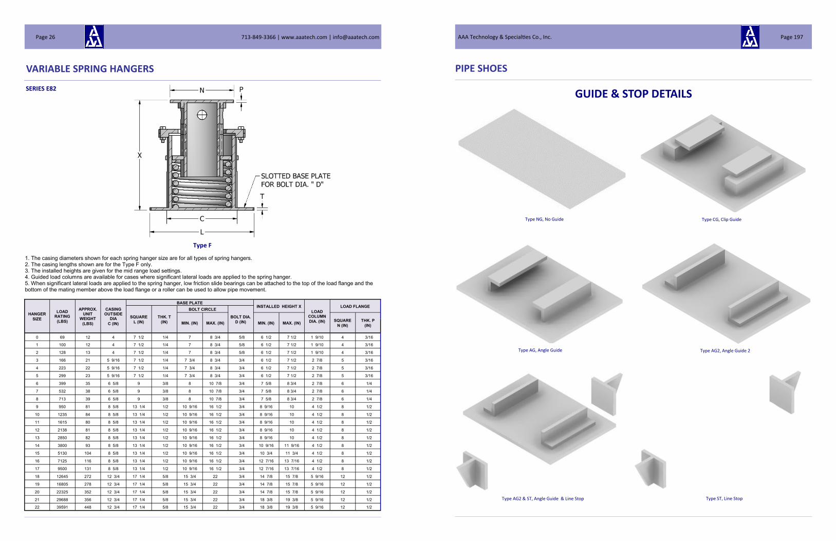
VARIABLE SPRING HANGERS
SERIES E82
Type F
HANGER
SIZE
LOAD RATING
(LBS)
APPROX. UNIT
WEIGHT
(LBS)
CASING OUTSIDE
DIA
C (IN)
BASE PLATE INSTALLED HEIGHT X
LOAD COLUMN
DIA. (IN)
LOAD FLANGE
SQUARE
L (IN)
THK. T
(IN)
BOLT CIRCLE
BOLT DIA.
D (IN) MIN. (IN) MAX. (IN) MIN. (IN) MAX. (IN) SQUARE
N (IN)
THK. P
(IN)
0 69 12 4 7 1/2 1/4 7 8 3/4 5/8 6 1/2 7 1/2 1 9/10 4 3/16
1 100 12 4 7 1/2 1/4 7 8 3/4 5/8 6 1/2 7 1/2 1 9/10 4 3/16
2 128 13 4 7 1/2 1/4 7 8 3/4 5/8 6 1/2 7 1/2 1 9/10 4 3/16
3 166 21 5 9/16 7 1/2 1/4 7 3/4 8 3/4 3/4 6 1/2 7 1/2 2 7/8 5 3/16
4 223 22 5 9/16 7 1/2 1/4 7 3/4 8 3/4 3/4 6 1/2 7 1/2 2 7/8 5 3/16
5 299 23 5 9/16 7 1/2 1/4 7 3/4 8 3/4 3/4 6 1/2 7 1/2 2 7/8 5 3/16
6 399 35 6 5/8 9 3/8 8 10 7/8 3/4 7 5/8 8 3/4 2 7/8 6 1/4
7 532 38 6 5/8 9 3/8 8 10 7/8 3/4 7 5/8 8 3/4 2 7/8 6 1/4
8 713 39 6 5/8 9 3/8 8 10 7/8 3/4 7 5/8 8 3/4 2 7/8 6 1/4
9 950 81 8 5/8 13 1/4 1/2 10 9/16 16 1/2 3/4 8 9/16 10 4 1/2 8 1/2
10 1235 84 8 5/8 13 1/4 1/2 10 9/16 16 1/2 3/4 8 9/16 10 4 1/2 8 1/2
11 1615 80 8 5/8 13 1/4 1/2 10 9/16 16 1/2 3/4 8 9/16 10 4 1/2 8 1/2
12 2138 81 8 5/8 13 1/4 1/2 10 9/16 16 1/2 3/4 8 9/16 10 4 1/2 8 1/2
13 2850 82 8 5/8 13 1/4 1/2 10 9/16 16 1/2 3/4 8 9/16 10 4 1/2 8 1/2
14 3800 93 8 5/8 13 1/4 1/2 10 9/16 16 1/2 3/4 10 9/16 11 9/16 4 1/2 8 1/2
15 5130 104 8 5/8 13 1/4 1/2 10 9/16 16 1/2 3/4 10 3/4 11 3/4 4 1/2 8 1/2
16 7125 116 8 5/8 13 1/4 1/2 10 9/16 16 1/2 3/4 12 7/16 13 7/16 4 1/2 8 1/2
17 9500 131 8 5/8 13 1/4 1/2 10 9/16 16 1/2 3/4 12 7/16 13 7/16 4 1/2 8 1/2
18 12645 272 12 3/4 17 1/4 5/8 15 3/4 22 3/4 14 7/8 15 7/8 5 9/16 12 1/2
19 16805 278 12 3/4 17 1/4 5/8 15 3/4 22 3/4 14 7/8 15 7/8 5 9/16 12 1/2
20 22325 352 12 3/4 17 1/4 5/8 15 3/4 22 3/4 14 7/8 15 7/8 5 9/16 12 1/2
21 29688 356 12 3/4 17 1/4 5/8 15 3/4 22 3/4 18 3/8 19 3/8 5 9/16 12 1/2
22 39591 448 12 3/4 17 1/4 5/8 15 3/4 22 3/4 18 3/8 19 3/8 5 9/16 12 1/2
1. The casing diameters shown for each spring hanger size are for all types of spring hangers. 2. The casing lengths shown are for the Type F only. 3. The installed heights are given for the mid range load settings. 4. Guided load columns are available for cases where significant lateral loads are applied to the spring hanger. 5. When significant lateral loads are applied to the spring hanger, low friction slide bearings can be attached to the top of the load flange and the bottom of the mating member above the load flange or a roller can be used to allow pipe movement.
713-849-3366 | www.aaatech.com | [email protected] Page 26
PIPE SHOES
GUIDE & STOP DETAILS
Type NG, No Guide Type CG, Clip Guide
Type AG, Angle Guide Type AG2, Angle Guide 2
Type AG2 & ST, Angle Guide & Line Stop Type ST, Line Stop
AAA Technology & Specialties Co., Inc. Page 197

SLOT OPTION DETAIL
Type S1, No Slots
Type S2, Expansion Slots
Type S3, Insulation Slots
Type S4, Expansion & Insulation Slots
PIPE SHOES
713-849-3366 | www.aaatech.com | [email protected] Page 196
VARIABLE SPRING HANGERS
SERIES E82
Type G
HANGER
SIZE
LOAD RATING EACH
(LBS)
APPROX ASSEMBLY
WEIGHT
(LBS)
ROD DIA.
A (IN)
R.H. TH'D LENGTH
(IN)
CASING LENGTH
B (IN)
CASING OUTSIDE
DIA
C (IN)
MIN. TH'D ENGAGE-
MENT
F (IN)
ROD TAKE-OUT
N (IN)
CHANNEL
SIZE
MAX C - C
(IN)
SPACE BETWEEN
CHANNELS
W (IN)
BOTTOM OF CASING TO CHANNEL
P (IN)
0 69 30 1/2 3 1/2 5 1/2 4 1 1/8 3 1/16 C3 X 4.1 24 5/8 1 1/2
1 100 32 1/2 3 1/2 5 1/2 4 1 1/8 3 1/16 C3 X 4.1 24 5/8 1 1/2
2 128 34 1/2 3 1/2 5 1/2 4 1 1/8 2 11/16 C3 X 4.1 24 5/8 1 1/2
3 166 38 1/2 3 1/2 5 1/2 5 9/16 1 1/8 2 11/16 C3 X 4.1 30 3/4 1 1/2
4 223 42 1/2 3 1/2 5 1/2 5 9/16 1 1/8 2 5/16 C3 X 4.1 30 3/4 1 1/2
5 299 44 1/2 3 1/2 5 1/2 5 9/16 1 1/8 2 3/8 C3 X 4.1 30 3/4 1 1/2
6 399 56 5/8 4 6 3/4 6 5/8 1 1/4 2 15/16 C3 X 4.1 36 1 2
7 532 65 5/8 4 6 3/4 6 5/8 1 1/4 2 11/16 C3 X 4.1 36 1 2
8 713 67 5/8 4 6 3/4 6 5/8 1 1/4 2 3/4 C3 X 4.1 36 1 2
9 950 128 3/4 4 7 11/16 8 5/8 1 1/2 3 13/16 C4 X 5.4 36 1 1/4 2
10 1235 142 3/4 4 7 11/16 8 5/8 1 1/2 2 7/8 C4 X 5.4 36 1 1/4 2
11 1615 130 3/4 5 7 11/16 8 5/8 1 1/2 3 1/4 C4 X 5.4 36 1 1/4 2
12 2138 138 1 5 7 11/16 8 5/8 1 3/4 2 11/16 C5 X 6.7 36 1 1/2 2
13 2850 162 1 5 7 11/16 8 5/8 1 3/4 3 7/16 C5 X 6.7 36 1 1/2 2
14 3800 172 1 1/4 5 9 5/8 8 5/8 2 1/8 2 11/16 C5 X 6.7 34 1 1/2 2
15 5130 212 1 1/4 5 9 5/8 8 5/8 2 1/8 2 C6 X 10.5 36 2 1/8 2
16 7125 244 1 1/2 6 11 15/16 8 5/8 2 5/8 3 1/8 C8 X 11.5 36 2 1/8 2
17 9500 288 1 3/4 7 11 15/16 8 5/8 2 7/8 3 1/2 C8 X 11.5 36 2 1/8 2
18 12645 566 2 7 14 3/8 12 3/4 3 1/8 2 3/4 C12 X 20.7 42 2 3/8 3
19 16805 618 2 1/4 8 14 3/8 12 3/4 3 7/16 3 3/8 C12 X 20.7 42 2 5/8 3
20 22325 764 2 1/2 9 14 3/8 12 3/4 3 11/16 3 1/4 C12 X 20.7 40 2 7/8 3
21 29688 884 2 3/4 9 18 1/8 12 3/4 4 1/16 3 C15 X 33.9 48 3 1/8 3
22 39591 1098 3 9 18 1/8 12 3/4 4 5/16 3 7/8 C15 X 33.9 48 3 3/8 3
1. The casing diameters shown for each spring hanger size are for all types of spring hangers. 2. The casing lengths shown are for Type G spring hangers. 3. The weights shown for all Type G spring hangers are based upon 24” center-to-center rod dimensions.
*Z = (F + N) - P
AAA Technology & Specialties Co., Inc. Page 27

SERIES E268
Type A Type B Type C
HANGER
SIZE
LOAD RATING
(LBS)
APPROX. UNIT
WEIGHT
(LBS)
ROD DIA.
A (IN)
R.H. TH'D
L'GTH
(IN)
CASING LENGTH
B (IN)
CASING OUT-SIDE DIA.
C (IN)
Z (IN)
MIN. TH'D
ENGAGE
F (IN)
TYPE
A TYPE B & C ROD TAKE-OUT
(IN) OVERALL LENGTH X (IN)
ROD EN-
GAGE
G (IN)
H
(IN)
R
(IN)
S
(IN)
T
(IN)
LUG HOLE DIA.
(IN)
TYPE A B & C TYPE A TYPES B & C
E J MIN. MAX MIN. MAX
0 69 10 1/2 3 1/2 8 1/4 4 1 1/4 1 1/8 1 2 7/8 1 1/4 1/4 11/16 8 10 3/4 10 13 12 3/8 15 3/8
1 100 11 1/2 3 1/2 8 1/4 4 1 1/4 1 1/8 1 2 7/8 1 1/4 1/4 11/16 8 10 3/4 10 13 12 3/8 15 3/8
2 128 12 1/2 3 1/2 8 1/4 4 1 1/4 1 1/8 1 2 7/8 1 1/4 1/4 11/16 8 10 3/4 10 13 12 3/8 15 3/8
3 166 15 1/2 3 1/2 8 3/4 5 9/16 1 1/4 1 1/8 1 2 7/8 1 1/4 1/4 11/16 8 1/2 11 1/4 10 1/2 13 1/2 12 7/8 15 7/8
4 223 18 1/2 3 1/2 8 3/4 5 9/16 1 1/4 1 1/8 1 2 7/8 1 1/4 1/4 11/16 8 1/2 11 1/4 10 1/2 13 1/2 12 7/8 15 7/8
5 299 20 1/2 3 1/2 8 3/4 5 9/16 1 1/4 1 1/8 1 2 7/8 1 1/4 1/4 11/16 8 1/2 11 1/4 10 1/2 13 1/2 12 7/8 15 7/8
6 399 28 5/8 4 8 13/16 6 5/8 1 3/8 1 1/4 1 1/8 2 7/8 1 1/4 1/4 13/16 8 9/16 11 5/16 10 13/16 13 13/16 13 1/16 16 1/16
7 532 31 5/8 4 8 13/16 6 5/8 1 3/8 1 1/4 1 1/8 2 7/8 1 1/4 1/4 13/16 8 9/16 11 5/16 10 13/16 13 13/16 13 1/16 16 1/16
8 713 33 5/8 4 8 13/16 6 5/8 1 3/8 1 1/4 1 1/8 2 7/8 1 1/4 1/4 13/16 8 9/16 11 5/16 10 13/16 13 13/16 13 1/16 16 1/16
9 950 68 3/4 4 11 1/16 8 5/8 1 5/8 1 1/2 1 7/16 2 1 1/8 1 1/2 3/8 15/16 10 11/16 13 9/16 13 7/16 16 7/16 15 13/16 18 13/16
10 1235 74 3/4 4 11 1/16 8 5/8 1 5/8 1 1/2 1 7/16 2 1 1/8 1 1/2 3/8 15/16 10 11/16 13 9/16 13 7/16 16 7/16 15 13/16 18 13/16
11 1615 70 3/4 5 11 1/16 8 5/8 1 5/8 1 1/2 1 7/16 2 1 1/8 1 1/2 3/8 15/16 10 11/16 13 9/16 13 7/16 16 7/16 15 13/16 18 13/16
12 2138 72 1 5 11 1/16 8 5/8 1 7/8 1 3/4 1 11/16 3 1 1/2 2 1/2 1 1/4 10 11/16 14 9/16 13 15/16 16 15/16 17 7/16 20 7/16
13 2850 91 1 5 11 1/16 8 5/8 1 7/8 1 3/4 1 11/16 3 1 1/2 2 1/2 1 1/4 10 11/16 14 9/16 13 15/16 16 15/16 17 7/16 20 7/16
14 3800 96 1 1/4 5 14 1/16 8 5/8 2 1/4 2 1/8 2 1/4 3 2 2 1/2 5/8 1 1/2 13 7/16 17 9/16 17 1/2 20 1/2 21 5/16 24 5/16
15 5130 121 1 1/4 5 14 1/16 8 5/8 2 1/4 2 1/8 2 1/4 3 2 2 1/2 5/8 1 1/2 13 7/16 17 9/16 17 1/2 20 1/2 21 5/16 24 5/16
16 7125 144 1 1/2 6 18 5/8 8 5/8 2 3/4 2 5/8 2 11/16 4 2 1/2 3 3/4 1 3/4 17 7/8 23 1/8 22 13/16 25 13/16 27 7/8 30 7/8
17 9500 172 1 3/4 7 18 5/8 8 5/8 3 2 7/8 2 15/16 5 2 1/2 3 3/4 3/4 2 17 7/8 24 1/8 23 5/16 26 5/16 29 1/8 32 1/8
18 12645 336 2 7 19 3/4 12 3/4 3 1/4 3 1/8 3 5/8 5 3 3 3/4 3/4 2 3/8 18 3/4 25 1/4 24 15/16 27 15/16 31 34
19 16805 382 2 1/4 8 19 3/4 12 3/4 3 5/8 3 7/16 3 13/16 5 3 4 1/4 3/4 2 5/8 18 3/4 25 1/4 25 9/16 28 9/16 31 5/16 34 5/16
20 22325 491 2 1/2 9 19 3/4 12 3/4 3 7/8 3 11/16 4 1/16 5 4 4 1/2 3/4 2 7/8 18 3/4 25 1/4 26 1/16 29 1/16 32 9/16 35 9/16
21 29688 502 2 3/4 9 26 3/4 12 3/4 4 1/4 4 1/16 4 11/16 5 4 5 3/4 3 1/8 25 1/2 32 1/4 33 11/16 36 11/16 39 15/16 42 15/16
22 39591 724 3 9 26 3/4 12 3/4 4 1/2 4 5/16 4 11/16 5 4 5 1 3 3/8 25 1/2 32 1/4 33 15/16 36 15/16 40 3/16 43 3/16
1. The casing diameters shown for each spring hanger size are for all types of spring hangers. 2. The casing lengths shown are for Types A, B and C. 3. All Rod Takeout dimensions shown in the table for Type A, B and C spring hangers are calculated with the spring hanger at the top of the move-ment scale. 4. All Minimum Overall Length values shown in the table for Type A, B and C spring hangers are calculated with the spring hanger at the top of the movement scale. All Maximum Overall Length values shown in the table for Type A, B and C spring hangers are calculated with the spring hanger at the bottom of the movement scale. To obtain the actual shipping length, add to the minimum overall length the deflection from the top of the scale (top of the working range) to the preset position.
VARIABLE SPRING HANGERS
713-849-3366 | www.aaatech.com | [email protected] Page 28
PIPE SHOES
HOW TO ORDER
T-Shoes are ordered by indicating the following dimensions and choices:
Fig. Description of Pipe Shoe
5000 Split Beam T-Shoe
5010 Split Beam T-Shoe w/U-Bolts
5020 Split Beam T-Shoe w/Clamps
5100 Fabricated T-Shoe
5110 Fabricated T-Shoe w/U-Bolts
5120 Fabricated T-Shoe w/Clamps
5200 Double Upright T-Shoe
5210 Double Upright T-Shoe w/U-Bolts
5220 Double Upright T-Shoe w/Clamps
Type Description of Guide Support
NG No Guide
CG Clip Guide
AG Angle Guide
AG2 Angle Guide 2
CG & ST Clip Guide and Line Stop
AG & ST Angle Guide and Line Stop
AG2 & ST Angle Guide 2 and Line Stop
ST Line Stop
Type Description of Slot Options
S1 No Slots
S2 Expansion Slots
S3 Insulation Band Slots
S4 Expansion Slots & Insulation Band Slots
Type Description of Slide Bearings
T/T PTFE on PTFE
S/T Stainless Steel on PTFE
S/P Stainless Steel on Polyethylene
S/G Stainless Steel on Graphite
G/G Graphite on Graphite
B/B Bronze on Bronze
S/M Stainless on Meehanite
Fig. Description of Pipe Shoe with Gusset Plates
5001 Split Beam T-Shoe with End Gusset Plates
5011 Split Beam T-Shoe w/U-Bolts with End Gusset Plates
5021 Split Beam T-Shoe w/Clamps with End Gusset Plates
5101 Fabricated T-Shoe with End Gusset Plates
5111 Fabricated T-Shoe w/U-Bolts with End Gusset Plates
5121 Fabricated T-Shoe w/Clamps with End Gusset Plates
AAA Technology & Specialties Co., Inc. Page 195

PIPE SHOES
SHOE TYPES Choose from three designs of pipe shoe: 1) Split Beam T-Shoe; 2) Fabricated (from flat bar) T-Shoe; or 3) Double Upright T-Shoe. Each design, in turn, can be fabricated : 1)
Plain; 2) With U-Bolts; or 3) With Clamps.
5000 - Split Beam—Plain 5010 - Split Beam with U-Bolts 5020 - Split Beam with Clamps
5100 - Fabricated-Plain 5110 - Fabricated with U-Bolts 5120 - Fabricated with Clamps
5200 - Double Upright—Plain 5210 - Double Upright with U-Bolts 5220 - Double Upright with Clamps
Fig. 5000, 5010, & 5020 SPLIT BEAM T-SHOES
Fig. 5100, 5110, 5120 FABRICATED T-SHOES
Fig. 5200, 5210, & 5220 DOUBLE UPRIGHT T-SHOES
713-849-3366 | www.aaatech.com | [email protected] Page 194
VARIABLE SPRING HANGERS
SERIES E268
Type D Type E
1. The casing diameters shown for each spring hanger size are for all types of spring hangers.
2. The casing lengths shown are for Type D and E spring hangers.
3. All Maximum Overall Length values shown in the table for Type D spring hangers are calculated with the spring hanger at the top of the move-
ment scale. All Minimum Overall Length values shown in the table for Type D spring hangers are calculated with the spring hanger at the bottom
of the movement scale. To obtain the actual shipping length, subtract from the maximum overall length the deflection from the top of the scale (top
of the working range) to the preset position.
4. For Type E spring hangers, the Maximum Overall Length is equal to the Casing Length B.
HANGER
SIZE
LOAD RATING
(LBS)
APPROX. UNIT
WEIGHT
(LBS)
ROD DIA.
A (IN)
R.H. TH'D LENGTH
(IN)
CASING LENGTH
B (IN)
CASING OUTSIDE
DIA
C (IN)
MIN. TH'D ENGAGE F
(IN)
ALLOW FOR
NUTS K (IN)
HEIGHT OF SPACER M
(MAX) (IN)
ROD LENGTH Y
(MAX) (IN) X MIN. X MAX
0 69 9 1/2 3 1/2 8 1/4 4 3/4 1 1/4 4 3/4 12 5/8 8 3/8 11 3/8
1 100 10 1/2 3 1/2 8 1/4 4 3/4 1 1/4 4 3/4 12 5/8 8 3/8 11 3/8
2 128 11 1/2 3 1/2 8 1/4 4 3/4 1 1/4 4 3/4 12 5/8 8 3/8 11 3/8
3 166 14 1/2 3 1/2 8 3/4 5 9/16 3/4 1 1/4 4 3/4 13 1/8 8 7/8 11 7/8
4 223 16 1/2 3 1/2 8 3/4 5 9/16 3/4 1 1/4 4 3/4 13 1/8 8 7/8 11 7/8
5 299 18 1/2 3 1/2 8 3/4 5 9/16 3/4 1 1/4 4 3/4 13 1/8 8 7/8 11 7/8
6 399 25 5/8 4 8 13/16 6 5/8 7/8 1 1/2 4 3/4 13 5/16 8 13/16 11 13/16
7 532 28 5/8 4 8 13/16 6 5/8 7/8 1 1/2 4 3/4 13 5/16 8 13/16 11 13/16
8 713 30 5/8 4 8 13/16 6 5/8 7/8 1 1/2 4 3/4 13 5/16 8 13/16 11 13/16
9 950 62 3/4 4 11 1/16 8 5/8 7/8 1 3/4 5 1/16 15 13/16 11 1/16 14 1/16
10 1235 67 3/4 4 11 1/16 8 5/8 7/8 1 3/4 4 15/16 15 13/16 11 1/16 14 1/16
11 1615 63 3/4 5 11 1/16 8 5/8 7/8 1 3/4 4 15/16 15 13/16 11 1/16 14 1/16
12 2138 64 1 5 11 1/16 8 5/8 1 1/2 2 1/4 5 1/16 16 5/16 11 1/16 14 1/16
13 2850 82 1 5 11 1/16 8 5/8 1 1/2 2 1/4 5 1/16 16 5/16 11 1/16 14 1/16
14 3800 86 1 1/4 5 14 1/16 8 5/8 1 5/8 2 1/2 5 5/8 19 9/16 14 1/16 17 1/16
15 5130 109 1 1/4 5 14 1/16 8 5/8 1 5/8 3 5 5/8 20 1/16 14 1/16 17 1/16
16 7125 130 1 1/2 6 18 5/8 8 5/8 1 3/4 3 1/2 6 1/8 25 1/8 18 5/8 21 5/8
17 9500 155 1 3/4 7 18 5/8 8 5/8 2 1/4 4 6 1/8 25 5/8 18 5/8 21 5/8
18 12645 302 2 7 19 3/4 12 3/4 2 1/2 4 9/16 6 15/16 27 5/16 19 3/4 22 3/4
19 16805 344 2 1/4 8 19 3/4 12 3/4 3 1/8 5 7 3/16 27 3/4 19 3/4 22 3/4
20 22325 440 2 1/2 9 19 3/4 12 3/4 3 1/8 5 9/16 7 3/16 28 5/16 19 3/4 22 3/4
21 29688 452 2 3/4 9 26 3/4 12 3/4 4 1/8 6 1/4 7 1/2 36 26 3/4 29 3/4
22 39591 651 3 9 26 3/4 12 3/4 4 1/2 6 5/8 7 1/2 36 3/8 26 3/4 29 3/4
AAA Technology & Specialties Co., Inc. Page 29

SERIES E268
Type F
HANGER
SIZE
LOAD RATING
(LBS)
APPROX. UNIT
WEIGHT
(LBS)
CASING OUTSIDE
DIA
C (IN)
BASE PLATE INSTALLED HEIGHT X
LOAD COLUMN
DIA. (IN)
LOAD FLANGE
SQUARE
L (IN)
THK. T
(IN)
BOLT CIRCLE
BOLT DIA.
D (IN) MIN. (IN) MAX. (IN) MIN. (IN) MAX. (IN) SQUARE
N (IN)
THK. P
(IN)
0 69 14 4 7 1/2 1/4 7 8 3/4 5/8 9 3/8 12 5/8 1 9/10 4 3/16
1 100 14 4 7 1/2 1/4 7 8 3/4 5/8 9 3/8 12 5/8 1 9/10 4 3/16
2 128 16 4 7 1/2 1/4 7 8 3/4 5/8 9 3/8 12 5/8 1 9/10 4 3/16
3 166 24 5 9/16 7 1/2 1/4 7 3/4 8 3/4 3/4 9 5/8 13 1/2 2 7/8 5 3/16
4 223 26 5 9/16 7 1/2 1/4 7 3/4 8 3/4 3/4 9 5/8 13 1/2 2 7/8 5 3/16
5 299 27 5 9/16 7 1/2 1/4 7 3/4 8 3/4 3/4 9 5/8 13 1/2 2 7/8 5 3/16
6 399 40 6 5/8 9 3/8 8 10 7/8 3/4 9 3/4 13 5/8 2 7/8 6 1/4
7 532 46 6 5/8 9 3/8 8 10 7/8 3/4 9 3/4 13 5/8 2 7/8 6 1/4
8 713 48 6 5/8 9 3/8 8 10 7/8 3/4 9 3/4 13 5/8 2 7/8 6 1/4
9 950 83 8 5/8 13 1/4 1/2 10 9/16 16 1/2 3/4 12 1/8 15 3/8 4 1/2 8 1/2
10 1235 90 8 5/8 13 1/4 1/2 10 9/16 16 1/2 3/4 12 1/8 15 3/8 4 1/2 8 1/2
11 1615 84 8 5/8 13 1/4 1/2 10 9/16 16 1/2 3/4 12 1/8 15 3/8 4 1/2 8 1/2
12 2138 87 8 5/8 13 1/4 1/2 10 9/16 16 1/2 3/4 12 1/8 15 3/8 4 1/2 8 1/2
13 2850 110 8 5/8 13 1/4 1/2 10 9/16 16 1/2 3/4 12 1/8 15 1/2 4 1/2 8 1/2
14 3800 116 8 5/8 13 1/4 1/2 10 9/16 16 1/2 3/4 15 1/4 18 4 1/2 8 1/2
15 5130 122 8 5/8 13 1/4 1/2 10 9/16 16 1/2 3/4 15 1/4 17 3/4 4 1/2 8 1/2
16 7125 140 8 5/8 13 1/4 1/2 10 9/16 16 1/2 3/4 18 5/8 20 7/8 4 1/2 8 1/2
17 9500 164 8 5/8 13 1/4 1/2 10 9/16 16 1/2 3/4 18 5/8 20 3/4 4 1/2 8 1/2
18 12645 319 12 3/4 17 1/4 5/8 15 3/4 22 3/4 20 1/8 22 7/8 5 9/16 12 1/2
19 16805 362 12 3/4 17 1/4 5/8 15 3/4 22 3/4 20 1/8 22 7/8 5 9/16 12 1/2
20 22325 464 12 3/4 17 1/4 5/8 15 3/4 22 3/4 20 3/8 22 7/8 5 9/16 12 1/2
21 29688 496 12 3/4 17 1/4 5/8 15 3/4 22 3/4 26 7/8 28 7/8 5 9/16 12 1/2
22 39591 660 12 3/4 17 1/4 5/8 15 3/4 22 3/4 27 28 5/8 5 9/16 12 1/2
1. The casing diameters shown for each spring hanger size are for all types of spring hangers. 2. The casing lengths shown are for the Type F only. 3. The installed heights are given for the mid range load settings. 4. Guided load columns are available for cases where significant lateral loads are applied to the spring hanger. 5. When significant lateral loads are applied to the spring hanger, low friction slide bearings can be attached to the top of the load flange and the bottom of the mating member above the load flange or a roller can be used to allow pipe movement. 6. Extended load columns are available where taller installed heights are required.
VARIABLE SPRING HANGERS
713-849-3366 | www.aaatech.com | [email protected] Page 30
PIPE SHOES
Pipe Shoes for Ambient and Hot Applications
AAA Technology & Specialty Co., Inc. is proud to provide a complete line of Pipe Shoes and Supports. These pipe shoes are con-
structed in accordance with the rules and regulations specified and defined by the Quality Assurance Procedures for Pipe Sup-
ports Manufactured per ASME B31.1, B31.2, B31.3, B31.4, B31.5, B31.8, B31.9 & B31.11 Piping Codes, the AWS D1.1 and the
MSS SP-58 Standards. Well trained and experienced personal using formal standardized document systems and fabrication
control methods supervise all projects.
The Pipe Shoes and Supports offered
herein are built in three categories:
Split Beam Construction, Welded Flat
Bar or Double Upright Construction in
accordance to your requirements. In
addition, we can supply the Shoe As-
semblies with Lateral Guides and/or
Line Stops as illustrated in the follow-
ing pages.
These shoes can be provided with our
TRI*SLIDE™ slide bearings. For tem-
peratures up to 300 °F (149 °C), we
offer slide bearings of PTFE over PTFE,
Stainless Steel over PTFE and Stainless
Steel over Polyethylene. For temper-
atures above 300 °F (149 °C), we offer
slide bearings of Graphite over Graph-
ite, Stainless Steel over Graphite,
Bronze over Bronze and Stainless
Steel over Meehanite.
For service temperatures from –20 °F
(-29 °C) to 750 °F (399 °C), structural carbon steel will be used in the pipe shoes. For service temperatures below –20 °F (-29 °
C), Charpy Impact Tested carbon steel materials will be use or Stainless Steel, as necessary, will be used. For service tempera-
tures from 751 °F (400 °C) to 1050 °F (566 °C) , alloy steel will be used in the construction of the pipe shoes. Above 1051 °F
(566 °C) , stainless steel will be used in the construction of the pipe shoes.
Please do not hesitate to call AAA Technology & Specialties Co., Inc. to tell us about your requirements so that we can better
serve you.
AAA Technology & Specialties Co., Inc. Page 193

DYNAMIC RESTRAINTS
U-BOLT RESTRAINT
U-2000 SERIES
Availability - 1/2" NPS to 12" NPS
Application -
Primarily to be used for small diameter piping which exerts low pulsation energy.
Provides more contact to piping than a round U-bolt when the Wide Flange Design
is used.
To be used where surrounding clearances limit the use of other types of mechani-
cal restraints.
Can be installed as only one strap, however is most effective when installed in
pairs.
Can be supplied with a Hot Dip Galvanized finish or PTFE Coating.
Supplied with 4 Heavy Hex Nuts.
STANDARD DESIGN OPTIONS
The Vibration Control Restraints described in this bulletin incorporate one of the following two
Elastomeric Bearing Pads:
Elastomeric Preformed Fabric Bearing Pads are bonded to all pipe contact bearing surfaces of the Clamps and Wedge
blocks to reduce structural borne noise, to distribute restraint loadings on the surface of the pipe and reduce localized
stress concentrations.
Elastomeric PTFE Slide Bearing Pads are bonded to all pipe contact bearing surfaces of the Clamps and Wedge blocks to
facilitate pipe movement due to thermal expansion and contraction and to reduce frictional resistance to this movement.
CONSTRUCTION OPTIONS
Material: Carbon Steel A-36 unless environmental conditions dictate otherwise
Finish: Hot Dip Galvanized, Black, Red Oxide Primer, CZ-11 or in accordance with Customer’s Paint Specification
Bearing Pad: Elastomeric Random Fiber, Elastomeric Preformed Fabric Pad, Elastomeric PTFE Slide Bearing Pad
Mounting: Anchor Bolts, Base Plate, Assembly Bolts, Nuts and Washers
HOW TO ORDER
Specify Restraint Type, Nominal Pipe Size or Outside Diameter, Elastomeric Pad Type, Finish, Accessories (i.e. base plate, bolts,
etc.) and the Quantity required.
Example: CP-3000 Restraint, 24”, with Elastomeric PTFE Slide Bearing Pads, Hot Dip Galvanized finish,
steel sole plate for concrete pier installation, anchor bolts, assembly bolts, heavy hex nuts and washers.
713-849-3366 | www.aaatech.com | [email protected] Page 192
VARIABLE SPRING HANGERS
SERIES E268
Type G
HANGER
SIZE
LOAD RATING EACH
(LBS)
APPROX ASSEMBLY
WEIGHT
(LBS)
ROD DIA.
A (IN)
R.H. TH'D LENGTH
(IN)
CASING LENGTH
B (IN)
CASING OUTSIDE
DIA
C (IN)
MIN. TH'D ENGAGE
F (IN)
ROD TAKE-OUT
N (IN)
CHANNEL
SIZE
MAX C - C
(IN)
SPACE BETWEEN
CHANNELS
W (IN)
BOTTOM OF CASING TO CHANNEL
P (IN)
0 69 0 1/2 3 1/2 8 1/4 4 1 1/8 3 1/16 C3 X 4.1 24 5/8 1 1/2
1 100 0 1/2 3 1/2 8 1/4 4 1 1/8 3 1/16 C3 X 4.1 24 5/8 1 1/2
2 128 0 1/2 3 1/2 8 1/4 4 1 1/8 2 11/16 C3 X 4.1 24 5/8 1 1/2
3 166 0 1/2 3 1/2 8 3/4 5 9/16 1 1/8 2 11/16 C3 X 4.1 30 3/4 1 1/2
4 223 0 1/2 3 1/2 8 3/4 5 9/16 1 1/8 2 5/16 C3 X 4.1 30 3/4 1 1/2
5 299 0 1/2 3 1/2 8 3/4 5 9/16 1 1/8 2 3/8 C3 X 4.1 30 3/4 1 1/2
6 399 0 5/8 4 8 13/16 6 5/8 1 1/4 2 15/16 C3 X 4.1 36 1 2
7 532 0 5/8 4 8 13/16 6 5/8 1 1/4 2 11/16 C3 X 4.1 36 1 2
8 713 0 5/8 4 8 13/16 6 5/8 1 1/4 2 3/4 C3 X 4.1 36 1 2
9 950 0 3/4 4 11 1/16 8 5/8 1 1/2 3 13/16 C4 X 5.4 36 1 1/4 2
10 1235 0 3/4 4 11 1/16 8 5/8 1 1/2 2 7/8 C4 X 5.4 36 1 1/4 2
11 1615 0 3/4 5 11 1/16 8 5/8 1 1/2 3 1/4 C4 X 5.4 36 1 1/4 2
12 2138 0 1 5 11 1/16 8 5/8 1 3/4 2 11/16 C5 X 6.7 36 1 1/2 2
13 2850 0 1 5 11 1/16 8 5/8 1 3/4 3 7/16 C5 X 6.7 36 1 1/2 2
14 3800 0 1 1/4 5 14 1/16 8 5/8 2 1/8 2 11/16 C5 X 6.7 34 1 1/2 2
15 5130 0 1 1/4 5 14 1/16 8 5/8 2 1/8 2 C6 X 10.5 36 2 1/8 2
16 7125 0 1 1/2 6 18 5/8 8 5/8 2 5/8 3 1/8 C8 X 11.5 36 2 1/8 2
17 9500 0 1 3/4 7 18 5/8 8 5/8 2 7/8 3 1/2 C8 X 11.5 36 2 1/8 2
18 12645 0 2 7 19 3/4 12 3/4 3 1/8 2 3/4 C12 X 20.7 42 2 3/8 3
19 16805 0 2 1/4 8 19 3/4 12 3/4 3 7/16 3 3/8 C12 X 20.7 42 2 5/8 3
20 22325 0 2 1/2 9 19 3/4 12 3/4 3 11/16 3 1/4 C12 X 20.7 40 2 7/8 3
21 29688 0 2 3/4 9 26 3/4 12 3/4 4 1/16 3 C15 X 33.9 48 3 1/8 3
22 39591 0 3 9 26 3/4 12 3/4 4 5/16 3 7/8 C15 X 33.9 48 3 3/8 3
1. The casing diameters shown for each spring hanger size are for all types of spring hangers. 2. The casing lengths shown are for Type G spring hangers. 3. The weights shown for all Type G spring hangers are based upon 24” center-to-center rod dimensions.
*Z = (F + N) - P
AAA Technology & Specialties Co., Inc. Page 31

VARIABLE SPRING HANGERS
SERIES E98
Type A Type B Type C
HANGER
SIZE
LOAD RATING
(LBS)
APPROX UNIT
WEIGHT
(LBS)
ROD DIA.
A
(IN)
R.H. TH'D
L'GTH
(IN)
CASING LENGTH
B (IN)
CASING OUTSIDE
DIA.
C (IN)
Z (IN)
MIN. TH'D
ENGAGE
F (IN)
TYPE A TYPE B & C ROD TAKE-OUT
(IN) OVERALL LENGTH X (IN)
ROD EN-
GAGE
G (IN)
H
(IN)
R
(IN)
S
(IN)
T
(IN)
LUG HOLE DIA.
(IN)
TYPE A B & C TYPE A TYPES B & C
E J MIN. MAX MIN. MAX
0 69 14 1/2 3 1/2 15 1/2 4 1 1/4 1 1/8 1 2 7/8 1 1/4 1/4 11/16 15 1/4 18 17 1/4 23 1/4 19 5/8 25 5/8
1 100 16 1/2 3 1/2 15 1/2 4 1 1/4 1 1/8 1 2 7/8 1 1/4 1/4 11/16 15 1/4 18 17 1/4 23 1/4 19 5/8 25 5/8
2 128 18 1/2 3 1/2 15 1/2 4 1 1/4 1 1/8 1 2 7/8 1 1/4 1/4 11/16 15 1/4 18 17 1/4 23 1/4 19 5/8 25 5/8
3 166 24 1/2 3 1/2 16 1/2 5 9/16 1 1/4 1 1/8 1 2 7/8 1 1/4 1/4 11/16 16 1/4 19 18 1/4 24 1/4 20 5/8 26 5/8
4 223 27 1/2 3 1/2 16 1/2 5 9/16 1 1/4 1 1/8 1 2 7/8 1 1/4 1/4 11/16 16 1/4 19 18 1/4 24 1/4 20 5/8 26 5/8
5 299 30 1/2 3 1/2 16 1/2 5 9/16 1 1/4 1 1/8 1 2 7/8 1 1/4 1/4 11/16 16 1/4 19 18 1/4 24 1/4 20 5/8 26 5/8
6 399 44 5/8 4 16 5/8 6 5/8 1 3/8 1 1/4 1 1/8 2 7/8 1 1/4 1/4 13/16 16 3/8 19 1/8 18 5/8 24 5/8 20 7/8 26 7/8
7 532 52 5/8 4 16 5/8 6 5/8 1 3/8 1 1/4 1 1/8 2 7/8 1 1/4 1/4 13/16 16 3/8 19 1/8 18 5/8 24 5/8 20 7/8 26 7/8
8 713 64 5/8 4 16 5/8 6 5/8 1 3/8 1 1/4 1 1/8 2 7/8 1 1/4 1/4 13/16 16 3/8 19 1/8 18 5/8 24 5/8 20 7/8 26 7/8
9 950 100 3/4 4 20 7/16 8 5/8 1 5/8 1 1/2 1 7/16 2 1 1/8 1 1/2 3/8 15/16 20 1/16 22 15/16 22
13/16
28
13/16 25 3/16 31 3/16
10 1235 120 3/4 4 20 7/16 8 5/8 1 5/8 1 1/2 1 7/16 2 1 1/8 1 1/2 3/8 15/16 20 1/16 22 15/16 22
13/16
28
13/16 25 3/16 31 3/16
11 1615 104 3/4 5 20 7/16 8 5/8 1 5/8 1 1/2 1 7/16 2 1 1/8 1 1/2 3/8 15/16 20 1/16 22 15/16 22
13/16
28
13/16 25 3/16 31 3/16
12 2138 114 1 5 20 7/16 8 5/8 1 7/8 1 3/4 1 11/16 3 1 1/2 2 1/2 1 1/4 20 1/16 23 15/16 23 5/16 29 5/16 26 13/16 32 13/16
13 2850 150 1 5 20 7/16 8 5/8 1 7/8 1 3/4 1 11/16 3 1 1/2 2 1/2 1 1/4 20 1/16 23 15/16 23 5/16 29 5/16 26 13/16 32 13/16
14 3800 159 1 1/4 5 25 7/8 8 5/8 2 1/4 2 1/8 2 1/4 3 2 2 1/2 5/8 1 1/2 25 1/4 29 3/8 29 5/16 35 5/16 33 1/8 39 1/8
15 5130 178 1 1/4 5 25 7/8 8 5/8 2 1/4 2 1/8 2 1/4 3 2 2 1/2 5/8 1 1/2 25 1/4 29 3/8 29 5/16 35 5/16 33 1/8 39 1/8
16 7125 226 1 1/2 6 34 3/8 8 5/8 2 3/4 2 5/8 2 11/16 4 2 1/2 3 3/4 1 3/4 33 5/8 38 7/8 38 9/16 44 9/16 43 5/8 49 5/8
17 9500 282 1 3/4 7 34 3/8 8 5/8 3 2 7/8 2 15/16 5 2 1/2 3 3/4 3/4 2 33 5/8 39 7/8 39 1/16 45 1/16 44 7/8 50 7/8
18 12645 520 2 7 34 7/16 12 3/4 3 1/4 3 1/8 3 5/8 5 3 3 3/4 3/4 2 3/8 33 7/16 39 15/16 39 5/8 45 5/8 45 11/16 51 11/16
19 16805 614 2 1/4 8 34 7/16 12 3/4 3 5/8 3 7/16 3 13/16 5 3 4 1/4 3/4 2 5/8 33 7/16 39 15/16 40 1/4 46 1/4 46 52
20 22325 826 2 1/2 9 34 7/16 12 3/4 3 7/8 3 11/16 4 1/16 5 4 4 1/2 3/4 2 7/8 33 7/16 39 15/16 40 3/4 46 3/4 47 1/4 53 1/4
21 29688 962 2 3/4 9 47 1/8 12 3/4 4 1/4 4 1/16 4 11/16 5 4 5 3/4 3 1/8 45 7/8 52 5/8 54 1/16 60 1/16 60 5/16 66 5/16
22 39591 1260 3 9 47 1/8 12 3/4 4 1/2 4 5/16 4 11/16 5 4 5 1 3 3/8 45 7/8 52 5/8 54 5/16 60 5/16 60 9/16 66 9/16
1. The casing diameters shown for each spring hanger size are for all types of spring hangers. 2. The casing lengths shown are for Types A, B and C. 3. All Rod Takeout dimensions shown in the table for Type A, B and C spring hangers are calculated with the spring hanger at the top of the move-ment scale. 4. All Minimum Overall Length values shown in the table for Type A, B and C spring hangers are calculated with the spring hanger at the top of the movement scale. All Maximum Overall Length values shown in the table for Type A, B and C spring hangers are calculated with the spring hanger at the bottom of the movement scale. To obtain the actual shipping length, add to the minimum overall length the deflection from the top of the scale (top of the working range) to the preset position.
713-849-3366 | www.aaatech.com | [email protected] Page 32
DYNAMIC RESTRAINTS
THERMAL-DYNAMIC RESTRAINT
with WEGDEBLOCK / SHIMBLOCK
TRW P-2000 Series Wedge block
TRB P-2000 Series Shim block
Availability - 6" NPS to 48" NPS
Application -
To enable complete adjustability in any direction which provides for optimiza-
tion of thermal and dynamic requirements for these restraints.
To control vibrations primarily in pulsation bottles and large diameter piping
which exhibit high pulsation energy and thermal movement.
To provide for load distribution in larger diameter piping or bottles.
To provide for easy access for pipe maintenance and inspection.
To provide for increased horizontal stiffness. To allow for added horizontal
flexibility to compensate for thermal movement, wedge blocks can be inter-
changed with shim blocks.
THERMAL GUIDE BOX CLAMP
BC-1000 SERIES
Availability - 6" NPS to 10" NPS
BC-2000 SERIES
Availability - 12" NPS to 48" NPS
Application -
To control vibrations primarily in piping which is subject to substantial move-
ments from significant changes in temperature.
To allow for horizontal movement while providing vertical dynamic stiffness.
THERMAL GUIDE BOX CLAMP
with SHIMBLOCK
BCSB-1000 SERIES
Availability - 6" NPS to 10" NPS
BCSB-2000 SERIES
Availability - 12" NPS to 48" NPS
Application -
To control vibrations primarily in piping which is subject to substantial move-
ments from significant changes in temperature.
To allow for horizontal movement while providing vertical dynamic stiffness.
To provide easy access for pipe maintenance and inspection, Shim blocks are
incorporated.
To allow for added horizontal stiffness, the Shim block SB-1000 can be re-
placed by a Wedge block WB-3000.
AAA Technology & Specialties Co., Inc. Page 191

VIBRATION CONTROL HOLD DOWN CLAMPS
FIG. WP-2000
WEDGE BLOCKS
PIPE
DIA
A
(in)
B
(in)
C
(in)
D
(in)
E
(in)
F
(in)
G
(in)
H
(in)
I
(in)
J
(in)
K
(in)
6 8 2 1/2 1/4 5/8 3 1/8 6 7/16 12 10 3/8 15 3/4 11
8 8 2 1/2 1/4 5/8 3 1/8 7 7/16 13 10 3/8 16 3/4 12
10 9 3 1/2 1/4 3/4 4 1/8 9 1/2 16 12 3/8 20 1/2 15
12 9 3 1/2 1/4 3/4 4 1/8 10 1/2 17 12 3/8 21 1/2 16
14 9 3 1/2 3/8 3/4 4 1/8 11 1/2 18 12 3/8 22 1/2 17
16 9 3 1/2 3/8 3/4 4 1/8 12 1/8 19 12 3/8 23 1/2 18
18 9 3 1/2 3/8 3/4 4 1/8 13 1/8 20 12 3/8 24 1/2 19
20 10 6 3/8 7/8 4 1/8 14 1/8 26 12 1/2 31 1/4 25
22 10 6 3/8 7/8 4 1/8 15 1/8 27 12 1/2 32 1/4 26
24 10 6 1/2 7/8 4 1/8 16 1/8 28 12 1/2 33 1/4 27
26 10 6 1/2 7/8 4 1/8 17 1/8 29 12 1/2 34 1/4 28
28 10 6 1/2 7/8 4 1/8 18 1/8 30 12 1/2 35 1/4 29
30 12 8 1/2 1/2 1 5 1/8 20 1/8 36 14 1/2 42 35
32 12 8 1/2 1/2 1 5 1/8 21 1/8 37 14 1/2 43 36
34 12 8 1/2 1/2 1 5 1/8 22 1/8 38 14 1/2 44 37
36 12 8 1/2 1/2 1 5 1/8 23 1/8 39 14 1/2 45 38
38 12 8 1/2 1/2 1 5 1/8 24 1/8 40 14 1/2 46 39
40 14 11 1/2 1 1/8 5 1/8 25 1/8 46 16 1/2 52 3/4 45
42 14 11 1/2 1 1/8 5 1/8 26 1/8 47 16 1/2 53 3/4 46
44 14 11 1/2 1 1/8 5 1/8 27 1/8 48 16 1/2 54 3/4 47
46 14 11 1/2 1 1/8 5 1/8 28 1/8 49 16 1/2 55 3/4 48
48 14 11 1/2 1 3/8 5 1/8 29 1/8 50 16 1/2 58 1/4 49
*F = Top of the plate and below the center of pipe
713-849-3366 | www.aaatech.com | [email protected] Page 190
VARIABLE SPRING HANGERS
SERIES E98
Type D Type E
HANGER
SIZE
LOAD RATING
(LBS)
APPROX. UNIT
WEIGHT
(LBS)
ROD DIA.
A (IN)
R.H. TH'D LENGTH
(IN)
CASING LENGTH
B (IN)
CASING OUTSIDE
DIA
C (IN)
MIN. TH'D ENGAGE F
(IN)
ALLOW FOR
NUTS K (IN)
HEIGHT OF SPACER M
(MAX) (IN)
ROD LENGTH Y
(MAX) (IN) X MIN. X MAX
0 69 14 1/2 3 1/2 15 1/2 4 3/4 1 1/4 8 1/2 22 1/4 15 21
1 100 15 1/2 3 1/2 15 1/2 4 3/4 1 1/4 8 1/2 22 1/4 15 21
2 128 17 1/2 3 1/2 15 1/2 4 3/4 1 1/4 8 1/2 22 1/4 15 21
3 166 23 1/2 3 1/2 16 1/2 5 9/16 3/4 1 1/4 8 1/2 23 1/4 16 22
4 223 25 1/2 3 1/2 16 1/2 5 9/16 3/4 1 1/4 8 1/2 23 1/4 16 22
5 299 28 1/2 3 1/2 16 1/2 5 9/16 3/4 1 1/4 8 1/2 23 1/4 16 22
6 399 41 5/8 4 16 5/8 6 5/8 7/8 1 1/2 8 1/2 23 5/8 16 1/8 22 1/8
7 532 49 5/8 4 16 5/8 6 5/8 7/8 1 1/2 8 1/2 23 5/8 16 1/8 22 1/8
8 713 61 5/8 4 16 5/8 6 5/8 7/8 1 1/2 8 1/2 23 5/8 16 1/8 22 1/8
9 950 95 3/4 4 20 7/16 8 5/8 7/8 1 3/4 8 11/16 27 11/16 19 15/16 25 15/16
10 1235 109 3/4 4 20 7/16 8 5/8 7/8 1 3/4 8 13/16 27 11/16 19 15/16 25 15/16
11 1615 94 3/4 5 20 7/16 8 5/8 7/8 1 3/4 8 13/16 27 11/16 19 15/16 25 15/16
12 2138 101 1 5 20 7/16 8 5/8 1 1/2 2 1/4 8 11/16 28 3/16 19 15/16 25 15/16
13 2850 136 1 5 20 7/16 8 5/8 1 1/2 2 1/4 8 13/16 28 3/16 19 15/16 25 15/16
14 3800 142 1 1/4 5 25 7/8 8 5/8 1 5/8 2 1/2 9 3/8 33 7/8 25 3/8 31 3/8
15 5130 164 1 1/4 5 25 7/8 8 5/8 1 5/8 3 9 3/8 34 3/8 25 3/8 31 3/8
16 7125 208 1 1/2 6 34 3/8 8 5/8 1 3/4 3 1/2 9 7/8 43 3/8 33 7/8 39 7/8
17 9500 262 1 3/4 7 34 3/8 8 5/8 2 1/4 4 9 7/8 43 7/8 33 7/8 39 7/8
18 12645 467 2 7 34 7/16 12 3/4 2 1/2 4 9/16 10 5/16 44 1/2 33 15/16 39 15/16
19 16805 553 2 1/4 8 34 7/16 12 3/4 3 1/8 5 10 9/16 44 15/16 33 15/16 39 15/16
20 22325 735 2 1/2 9 34 7/16 12 3/4 3 1/8 5 9/16 10 9/16 45 1/2 33 15/16 39 15/16
21 29688 855 2 3/4 9 47 1/8 12 3/4 4 1/8 6 1/4 11 3/8 58 7/8 46 5/8 52 5/8
22 39591 1109 3 9 47 1/8 12 3/4 4 1/2 6 5/8 11 3/8 59 1/4 46 5/8 52 5/8
1. The casing diameters shown for each spring hanger size are for all types of spring hangers.
2. The casing lengths shown are for Type D and E spring hangers.
3. All Maximum Overall Length values shown in the table for Type D spring hangers are calculated with the spring hanger at the top of the move-
ment scale. All Minimum Overall Length values shown in the table for Type D spring hangers are calculated with the spring hanger at the bottom
of the movement scale. To obtain the actual shipping length, subtract from the maximum overall length the deflection from the top of the scale
(top of the working range) to the preset position.
AAA Technology & Specialties Co., Inc. Page 33

VARIABLE SPRING HANGERS
SERIES E98
Type F
HANGER
SIZE
LOAD RATING
(LBS)
APPROX. UNIT
WEIGHT
(LBS)
CASING OUTSIDE
DIA
C (IN)
BASE PLATE INSTALLED HEIGHT X
LOAD COLUMN
DIA. (IN)
LOAD FLANGE
SQUARE
L (IN)
THK. T
(IN)
BOLT CIRCLE
BOLT DIA.
D (IN) MIN. (IN) MAX. (IN) MIN. (IN) MAX. (IN) SQUARE
N (IN)
THK. P
(IN)
0 69 22 4 7 1/2 1/4 7 8 3/4 5/8 16 5/8 22 1/8 1 9/10 4 3/16
1 100 24 4 7 1/2 1/4 7 8 3/4 5/8 16 5/8 22 1/8 1 9/10 4 3/16
2 128 26 4 7 1/2 1/4 7 8 3/4 5/8 16 5/8 22 1/8 1 9/10 4 3/16
3 166 37 5 9/16 7 1/2 1/4 7 3/4 8 3/4 3/4 17 3/8 23 2 7/8 5 3/16
4 223 41 5 9/16 7 1/2 1/4 7 3/4 8 3/4 3/4 17 3/8 23 2 7/8 5 3/16
5 299 45 5 9/16 7 1/2 1/4 7 3/4 8 3/4 3/4 17 3/8 23 2 7/8 5 3/16
6 399 66 6 5/8 9 3/8 8 10 7/8 3/4 17 1/2 23 1/8 2 7/8 6 1/4
7 532 79 6 5/8 9 3/8 8 10 7/8 3/4 17 1/2 23 1/8 2 7/8 6 1/4
8 713 80 6 5/8 9 3/8 8 10 7/8 3/4 17 1/2 23 1/8 2 7/8 6 1/4
9 950 140 8 5/8 13 1/4 1/2 10 9/16 16 1/2 3/4 21 3/8 25 5/8 4 1/2 8 1/2
10 1235 154 8 5/8 13 1/4 1/2 10 9/16 16 1/2 3/4 21 3/8 25 5/8 4 1/2 8 1/2
11 1615 140 8 5/8 13 1/4 1/2 10 9/16 16 1/2 3/4 21 3/8 25 5/8 4 1/2 8 1/2
12 2138 148 8 5/8 13 1/4 1/2 10 9/16 16 1/2 3/4 21 3/8 25 5/8 4 1/2 8 1/2
13 2850 190 8 5/8 13 1/4 1/2 10 9/16 16 1/2 3/4 21 3/8 26 4 1/2 8 1/2
14 3800 194 8 5/8 13 1/4 1/2 10 9/16 16 1/2 3/4 27 31 4 1/2 8 1/2
15 5130 206 8 5/8 13 1/4 1/2 10 9/16 16 1/2 3/4 27 30 3/4 4 1/2 8 1/2
16 7125 246 8 5/8 13 1/4 1/2 10 9/16 16 1/2 3/4 33 1/2 37 4 1/2 8 1/2
17 9500 292 8 5/8 13 1/4 1/2 10 9/16 16 1/2 3/4 33 1/2 36 3/4 4 1/2 8 1/2
18 12645 558 12 3/4 17 1/4 5/8 15 3/4 22 3/4 35 3/8 39 3/8 5 9/16 12 1/2
19 16805 632 12 3/4 17 1/4 5/8 15 3/4 22 3/4 35 3/8 39 3/8 5 9/16 12 1/2
20 22325 822 12 3/4 17 1/4 5/8 15 3/4 22 3/4 35 3/8 39 3/8 5 9/16 12 1/2
21 29688 890 12 3/4 17 1/4 5/8 15 3/4 22 3/4 48 1/8 51 3/8 5 9/16 12 1/2
22 39591 1140 12 3/4 17 1/4 5/8 15 3/4 22 3/4 48 1/4 51 1/8 5 9/16 12 1/2
1. The casing diameters shown for each spring hanger size are for all types of spring hangers. 2. The casing lengths shown are for Type F only. 3. The installed heights are given for the mid range load settings. 4. Guided load columns are available for cases where significant lateral loads are applied to the spring hanger. 5. When significant lateral loads are applied to the spring hanger, low friction slide bearings can be attached to the top of the load flange and the bottom of the mating member above the load flange or a roller can be used to allow pipe movement. 6. Extended load columns are available where taller installed heights are required.
713-849-3366 | www.aaatech.com | [email protected] Page 34
VIBRATION CONTROL HOLD DOWN CLAMPS
FIG. CWP-4000
HOLD DOWN CLAMP W/ WEDGE BLOCKS
PIPE
DIA
A
(in)
B
(in)
C
(in)
D
(in)
E
(in)
F
(in)
G
(in)
H
(in)
I
(in)
B2
(in)
L
(in)
R
(in)
T
(in)
T2
(in)
W
(in)
6 16 12 1/2 3 1/8 5/8 6 6 13 6 7/16 2 1/2 3 15 3/4 3 7/16 3/8 1/4 11
8 18 14 1/2 3 1/8 5/8 7 6 13 7 7/16 2 1/2 3 16 3/4 4 7/16 3/8 1/4 11
10 21 3/4 17 1/2 4 1/8 3/4 9 7 14 1/4 9 1/2 3 1/2 3 20 1/2 5 1/2 1/2 1/4 14 1/4
12 23 3/4 20 4 1/8 3/4 10 7 14 1/4 10 1/2 3 1/2 3 1/2 21 1/2 6 1/2 1/2 1/4 14 1/4
14 25 21 1/4 4 1/8 3/4 10 5/8 7 14 1/4 11 1/8 3 1/2 3 1/2 22 1/2 7 1/8 1/2 3/8 14 1/4
16 27 23 1/4 4 1/8 3/4 11 5/8 7 14 1/4 12 1/8 3 1/2 3 1/2 23 1/2 8 1/8 1/2 3/8 14 1/4
18 29 25 1/4 4 1/8 3/4 12 5/8 7 14 1/4 13 1/8 3 1/2 3 1/2 24 1/2 9 1/8 1/2 3/8 14 1/4
20 33 1/4 29 1/8 4 1/8 7/8 13 5/8 8 16 1/2 14 1/8 6 4 31 1/4 10 1/8 5/8 3/8 16 1/2
22 35 1/4 31 1/8 4 1/8 7/8 14 5/8 8 16 1/2 15 1/8 6 4 32 1/4 11 1/8 5/8 3/8 16 1/2
24 37 1/4 33 1/8 4 1/8 7/8 15 5/8 8 16 1/2 16 1/8 6 4 33 1/4 12 1/8 5/8 1/2 16 1/2
26 39 1/4 35 1/8 4 1/8 7/8 16 5/8 8 16 1/2 17 1/8 6 4 34 1/4 13 1/8 5/8 1/2 16 1/2
28 41 1/4 37 1/8 4 1/8 7/8 17 5/8 8 16 1/2 18 1/8 6 4 35 1/4 14 1/8 5/8 1/2 16 1/2
30 44 1/2 40 5 1/8 1 19 5/8 10 19 20 1/8 8 1/2 5 42 15 1/8 3/4 1/2 19
32 46 1/2 42 5 1/8 1 20 5/8 10 19 21 1/8 8 1/2 5 43 16 1/8 3/4 1/2 19
34 48 1/2 44 5 1/8 1 21 5/8 10 19 22 1/8 8 1/2 5 44 17 1/8 3/4 1/2 19
36 50 1/2 46 5 1/8 1 22 5/8 10 19 23 1/8 8 1/2 5 45 18 1/8 3/4 1/2 19
38 52 1/2 48 5 1/8 1 23 5/8 10 19 24 1/8 8 1/2 5 46 19 1/8 3/4 1/2 19
40 55 3/4 50 7/8 5 1/8 1 1/8 24 5/8 12 22 25 1/8 11 6 52 3/4 20 1/8 7/8 1/2 22
42 57 3/4 52 7/8 5 1/8 1 1/8 25 5/8 12 22 26 1/8 11 6 53 3/4 21 1/8 7/8 1/2 22
44 59 3/4 54 7/8 5 1/8 1 1/8 26 5/8 12 22 27 1/8 11 6 54 3/4 22 1/8 7/8 1/2 22
46 61 3/4 56 7/8 5 1/8 1 1/8 27 5/8 12 22 28 1/8 11 6 55 3/4 23 1/8 7/8 1/2 22
48 63 3/4 58 7/8 5 1/8 1 3/8 28 5/8 12 22 29 1/8 11 6 58 1/4 24 1/8 7/8 1/2 22
AAA Technology & Specialties Co., Inc. Page 189

VIBRATION CONTROL HOLD DOWN CLAMPS
FIG. CP-3500
EXTRA HEAVY HOLD DOWN CLAMP
PIPE
DIA
A
(in)
B
(in)
C
(in)
D
(in)
E
(in)
F
(in)
G
(in)
H
(in)
R
(in)
T
(in)
T2
(in)
U
(in)
V
(in)
ANCHOR BOLT
(in)
4" 11 3/4 8 3/4 3 1 7/8 6 5/8 7/8 1 1/2 2 7/16 3/8 3/8 3 5 3/4
5" 13 7/8 10 1/2 3 2 13/32 6 3/4 1 1 1/2 3 1/2 1/2 4 5 7/8
6" 15 7/8 12 3 2 15/16 6 3/4 1 1 1/2 3 1/2 1/2 1/2 4 5 7/8
8" 17 7/8 13 7/8 3 3 15/16 6 1 1 1 1/2 4 1/2 1/2 1/2 4 5 7/8
10" 21 1/2 17 1/4 3 1/2 5 7 1 1 1/8 1 3/4 5 9/16 5/8 5/8 5 6 1
12" 23 1/2 19 1/4 3 1/2 6 7 1 1 1/8 1 3/4 6 9/16 5/8 5/8 6 6 1
14" 24 3/4 20 1/2 3 1/2 6 5/8 7 1 1 1/8 1 3/4 7 3/16 5/8 5/8 6 6 1
16" 26 3/4 22 1/2 3 1/2 7 5/8 7 1 1 1/8 1 3/4 8 3/16 5/8 5/8 6 6 1
18" 28 3/4 24 1/2 3 1/2 8 5/8 7 1 1 1/8 1 3/4 9 3/16 5/8 5/8 6 6 1
20" 33 28 1/2 4 9 5/8 8 1 1/4 1 1/4 2 1/4 10 3/16 3/4 3/4 7 7 1 1/8
24" 37 32 1/2 4 11 5/8 8 1 1/4 1 1/4 2 1/4 12 3/16 3/4 3/4 7 7 1 1/8
26" 39 34 1/2 4 12 5/8 8 1 1/4 1 1/4 2 1/4 13 3/16 3/4 3/4 7 7 1 1/8
28" 41 36 1/2 4 13 5/8 8 1 1/4 1 1/4 2 1/4 14 3/16 3/4 3/4 7 7 1 1/8
30" 44 3/4 39 3/4 5 14 5/8 10 1 1/4 1 1/2 2 1/2 15 3/16 7/8 7/8 9 9 1 1/4
32" 46 3/4 40 3/4 5 15 5/8 10 1 1/2 1 1/2 2 1/2 16 3/16 7/8 7/8 9 9 1 1/4
36" 50 3/4 44 3/4 5 17 5/8 10 1 1/2 1 1/2 2 1/2 18 3/16 7/8 7/8 9 9 1 1/4
40" 56 1/2 50 1/2 5 19 5/8 10 1 1/2 1 1/2 2 1/2 20 3/16 1 1 9 9 1 1/4
42" 59 1/4 52 1/4 6 20 5/8 12 1 1/2 1 3/4 3 1/2 21 3/16 1 1 11 11 1 1/2
48" 66 1/4 58 1/4 6 23 5/8 12 1 1/2 1 3/4 3 1/2 24 3/16 1 1/4 1 1/4 11 11 1 1/2
713-849-3366 | www.aaatech.com | [email protected] Page 188
VARIABLE SPRING HANGERS
SERIES E98
Type G
HANGER
SIZE
LOAD RATING EACH
(LBS)
APPROX ASSEMBLY
WEIGHT
(LBS)
ROD DIA.
A (IN)
R.H. TH'D LENGTH
(IN)
CASING LENGTH
B (IN)
CASING OUTSIDE
DIA
C (IN)
MIN. TH'D ENGAGE
F (IN)
ROD TAKE-OUT
N (IN)
CHANNEL
SIZE
MAX C - C
(IN)
SPACE BETWEEN
CHANNELS
W (IN)
BOTTOM OF CASING TO CHANNEL
P (IN)
0 69 41 1/2 3 1/2 15 1/2 4 1 1/8 3 1/16 C3 X 4.1 24 5/8 1 1/2
1 100 43 1/2 3 1/2 15 1/2 4 1 1/8 3 1/16 C3 X 4.1 24 5/8 1 1/2
2 128 47 1/2 3 1/2 15 1/2 4 1 1/8 2 11/16 C3 X 4.1 24 5/8 1 1/2
3 166 58 1/2 3 1/2 16 1/2 5 9/16 1 1/8 2 11/16 C3 X 4.1 30 3/4 1 1/2
4 223 62 1/2 3 1/2 16 1/2 5 9/16 1 1/8 2 5/16 C3 X 4.1 30 3/4 1 1/2
5 299 68 1/2 3 1/2 16 1/2 5 9/16 1 1/8 2 3/8 C3 X 4.1 30 3/4 1 1/2
6 399 94 5/8 4 16 5/8 6 5/8 1 1/4 2 15/16 C3 X 4.1 36 1 2
7 532 110 5/8 4 16 5/8 6 5/8 1 1/4 2 11/16 C3 X 4.1 36 1 2
8 713 134 5/8 4 16 5/8 6 5/8 1 1/4 2 3/4 C3 X 4.1 36 1 2
9 950 204 3/4 4 20 7/16 8 5/8 1 1/2 3 13/16 C4 X 5.4 36 1 1/4 2
10 1235 232 3/4 4 20 7/16 8 5/8 1 1/2 2 7/8 C4 X 5.4 36 1 1/4 2
11 1615 202 3/4 5 20 7/16 8 5/8 1 1/2 3 1/4 C4 X 5.4 36 1 1/4 2
12 2138 220 1 5 20 7/16 8 5/8 1 3/4 2 11/16 C5 X 6.7 36 1 1/2 2
13 2850 290 1 5 20 7/16 8 5/8 1 3/4 3 7/16 C5 X 6.7 36 1 1/2 2
14 3800 302 1 1/4 5 25 7/8 8 5/8 2 1/8 2 11/16 C5 X 6.7 34 1 1/2 2
15 5130 356 1 1/4 5 25 7/8 8 5/8 2 1/8 2 C6 X 10.5 36 2 1/8 2
16 7125 447 1 1/2 6 34 3/8 8 5/8 2 5/8 3 1/8 C8 X 11.5 36 2 1/8 2
17 9500 555 1 3/4 7 34 3/8 8 5/8 2 7/8 3 1/2 C8 X 11.5 36 2 1/8 2
18 12645 976 2 7 34 7/16 12 3/4 3 1/8 2 3/4 C12 X 20.7 42 2 3/8 3
19 16805 1148 2 1/4 8 34 7/16 12 3/4 3 7/16 3 3/8 C12 X 20.7 42 2 5/8 3
20 22325 1512 2 1/2 9 34 7/16 12 3/4 3 11/16 3 1/4 C12 X 20.7 40 2 7/8 3
21 29688 1778 2 3/4 9 47 1/8 12 3/4 4 1/16 3 C15 X 33.9 48 3 1/8 3
22 39591 2286 3 9 47 1/8 12 3/4 4 5/16 3 7/8 C15 X 33.9 48 3 3/8 3
1. The casing diameters shown for each spring hanger size are for all types of spring hangers. 2. The casing lengths shown are for Type G spring hangers. 3. The weights shown for all Type G spring hangers are based upon 24” center-to-center rod dimensions.
*Z = (F + N) - P
AAA Technology & Specialties Co., Inc. Page 35
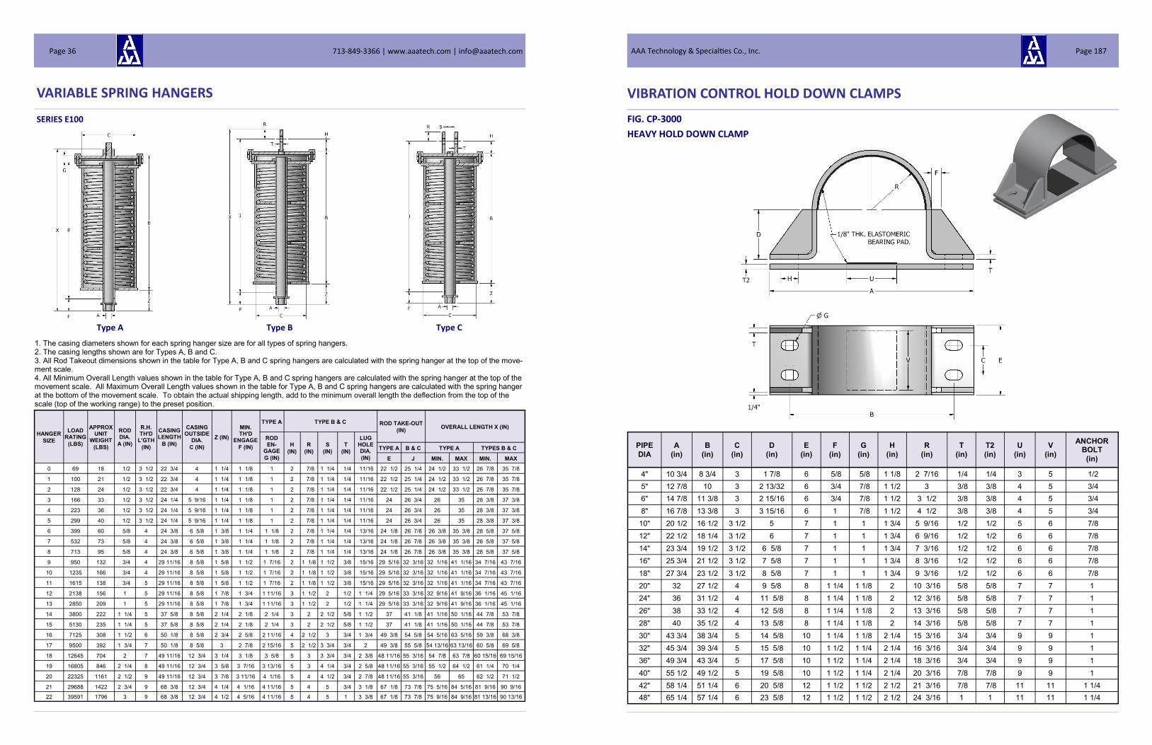
VARIABLE SPRING HANGERS
SERIES E100
Type A Type B Type C
HANGER
SIZE
LOAD RATING
(LBS)
APPROX UNIT
WEIGHT
(LBS)
ROD DIA.
A (IN)
R.H. TH'D
L'GTH
(IN)
CASING LENGTH
B (IN)
CASING OUTSIDE
DIA.
C (IN)
Z (IN)
MIN. TH'D
ENGAGE
F (IN)
TYPE A TYPE B & C ROD TAKE-OUT
(IN) OVERALL LENGTH X (IN)
ROD EN-
GAGE
G (IN)
H
(IN)
R
(IN)
S
(IN)
T
(IN)
LUG HOLE DIA.
(IN)
TYPE A B & C TYPE A TYPES B & C
E J MIN. MAX MIN. MAX
0 69 18 1/2 3 1/2 22 3/4 4 1 1/4 1 1/8 1 2 7/8 1 1/4 1/4 11/16 22 1/2 25 1/4 24 1/2 33 1/2 26 7/8 35 7/8
1 100 21 1/2 3 1/2 22 3/4 4 1 1/4 1 1/8 1 2 7/8 1 1/4 1/4 11/16 22 1/2 25 1/4 24 1/2 33 1/2 26 7/8 35 7/8
2 128 24 1/2 3 1/2 22 3/4 4 1 1/4 1 1/8 1 2 7/8 1 1/4 1/4 11/16 22 1/2 25 1/4 24 1/2 33 1/2 26 7/8 35 7/8
3 166 33 1/2 3 1/2 24 1/4 5 9/16 1 1/4 1 1/8 1 2 7/8 1 1/4 1/4 11/16 24 26 3/4 26 35 28 3/8 37 3/8
4 223 36 1/2 3 1/2 24 1/4 5 9/16 1 1/4 1 1/8 1 2 7/8 1 1/4 1/4 11/16 24 26 3/4 26 35 28 3/8 37 3/8
5 299 40 1/2 3 1/2 24 1/4 5 9/16 1 1/4 1 1/8 1 2 7/8 1 1/4 1/4 11/16 24 26 3/4 26 35 28 3/8 37 3/8
6 399 60 5/8 4 24 3/8 6 5/8 1 3/8 1 1/4 1 1/8 2 7/8 1 1/4 1/4 13/16 24 1/8 26 7/8 26 3/8 35 3/8 28 5/8 37 5/8
7 532 73 5/8 4 24 3/8 6 5/8 1 3/8 1 1/4 1 1/8 2 7/8 1 1/4 1/4 13/16 24 1/8 26 7/8 26 3/8 35 3/8 28 5/8 37 5/8
8 713 95 5/8 4 24 3/8 6 5/8 1 3/8 1 1/4 1 1/8 2 7/8 1 1/4 1/4 13/16 24 1/8 26 7/8 26 3/8 35 3/8 28 5/8 37 5/8
9 950 132 3/4 4 29 11/16 8 5/8 1 5/8 1 1/2 1 7/16 2 1 1/8 1 1/2 3/8 15/16 29 5/16 32 3/16 32 1/16 41 1/16 34 7/16 43 7/16
10 1235 166 3/4 4 29 11/16 8 5/8 1 5/8 1 1/2 1 7/16 2 1 1/8 1 1/2 3/8 15/16 29 5/16 32 3/16 32 1/16 41 1/16 34 7/16 43 7/16
11 1615 138 3/4 5 29 11/16 8 5/8 1 5/8 1 1/2 1 7/16 2 1 1/8 1 1/2 3/8 15/16 29 5/16 32 3/16 32 1/16 41 1/16 34 7/16 43 7/16
12 2138 156 1 5 29 11/16 8 5/8 1 7/8 1 3/4 1 11/16 3 1 1/2 2 1/2 1 1/4 29 5/16 33 3/16 32 9/16 41 9/16 36 1/16 45 1/16
13 2850 209 1 5 29 11/16 8 5/8 1 7/8 1 3/4 1 11/16 3 1 1/2 2 1/2 1 1/4 29 5/16 33 3/16 32 9/16 41 9/16 36 1/16 45 1/16
14 3800 222 1 1/4 5 37 5/8 8 5/8 2 1/4 2 1/8 2 1/4 3 2 2 1/2 5/8 1 1/2 37 41 1/8 41 1/16 50 1/16 44 7/8 53 7/8
15 5130 235 1 1/4 5 37 5/8 8 5/8 2 1/4 2 1/8 2 1/4 3 2 2 1/2 5/8 1 1/2 37 41 1/8 41 1/16 50 1/16 44 7/8 53 7/8
16 7125 308 1 1/2 6 50 1/8 8 5/8 2 3/4 2 5/8 2 11/16 4 2 1/2 3 3/4 1 3/4 49 3/8 54 5/8 54 5/16 63 5/16 59 3/8 68 3/8
17 9500 392 1 3/4 7 50 1/8 8 5/8 3 2 7/8 2 15/16 5 2 1/2 3 3/4 3/4 2 49 3/8 55 5/8 54 13/16 63 13/16 60 5/8 69 5/8
18 12645 704 2 7 49 11/16 12 3/4 3 1/4 3 1/8 3 5/8 5 3 3 3/4 3/4 2 3/8 48 11/16 55 3/16 54 7/8 63 7/8 60 15/16 69 15/16
19 16805 846 2 1/4 8 49 11/16 12 3/4 3 5/8 3 7/16 3 13/16 5 3 4 1/4 3/4 2 5/8 48 11/16 55 3/16 55 1/2 64 1/2 61 1/4 70 1/4
20 22325 1161 2 1/2 9 49 11/16 12 3/4 3 7/8 3 11/16 4 1/16 5 4 4 1/2 3/4 2 7/8 48 11/16 55 3/16 56 65 62 1/2 71 1/2
21 29688 1422 2 3/4 9 68 3/8 12 3/4 4 1/4 4 1/16 4 11/16 5 4 5 3/4 3 1/8 67 1/8 73 7/8 75 5/16 84 5/16 81 9/16 90 9/16
22 39591 1796 3 9 68 3/8 12 3/4 4 1/2 4 5/16 4 11/16 5 4 5 1 3 3/8 67 1/8 73 7/8 75 9/16 84 9/16 81 13/16 90 13/16
1. The casing diameters shown for each spring hanger size are for all types of spring hangers. 2. The casing lengths shown are for Types A, B and C. 3. All Rod Takeout dimensions shown in the table for Type A, B and C spring hangers are calculated with the spring hanger at the top of the move-ment scale. 4. All Minimum Overall Length values shown in the table for Type A, B and C spring hangers are calculated with the spring hanger at the top of the movement scale. All Maximum Overall Length values shown in the table for Type A, B and C spring hangers are calculated with the spring hanger at the bottom of the movement scale. To obtain the actual shipping length, add to the minimum overall length the deflection from the top of the scale (top of the working range) to the preset position.
713-849-3366 | www.aaatech.com | [email protected] Page 36
VIBRATION CONTROL HOLD DOWN CLAMPS
FIG. CP-3000
HEAVY HOLD DOWN CLAMP
PIPE
DIA
A
(in)
B
(in)
C
(in)
D
(in)
E
(in)
F
(in)
G
(in)
H
(in)
R
(in)
T
(in)
T2
(in)
U
(in)
V
(in)
ANCHOR BOLT
(in)
4" 10 3/4 8 3/4 3 1 7/8 6 5/8 5/8 1 1/8 2 7/16 1/4 1/4 3 5 1/2
5" 12 7/8 10 3 2 13/32 6 3/4 7/8 1 1/2 3 3/8 3/8 4 5 3/4
6" 14 7/8 11 3/8 3 2 15/16 6 3/4 7/8 1 1/2 3 1/2 3/8 3/8 4 5 3/4
8" 16 7/8 13 3/8 3 3 15/16 6 1 7/8 1 1/2 4 1/2 3/8 3/8 4 5 3/4
10" 20 1/2 16 1/2 3 1/2 5 7 1 1 1 3/4 5 9/16 1/2 1/2 5 6 7/8
12" 22 1/2 18 1/4 3 1/2 6 7 1 1 1 3/4 6 9/16 1/2 1/2 6 6 7/8
14" 23 3/4 19 1/2 3 1/2 6 5/8 7 1 1 1 3/4 7 3/16 1/2 1/2 6 6 7/8
16" 25 3/4 21 1/2 3 1/2 7 5/8 7 1 1 1 3/4 8 3/16 1/2 1/2 6 6 7/8
18" 27 3/4 23 1/2 3 1/2 8 5/8 7 1 1 1 3/4 9 3/16 1/2 1/2 6 6 7/8
20" 32 27 1/2 4 9 5/8 8 1 1/4 1 1/8 2 10 3/16 5/8 5/8 7 7 1
24" 36 31 1/2 4 11 5/8 8 1 1/4 1 1/8 2 12 3/16 5/8 5/8 7 7 1
26" 38 33 1/2 4 12 5/8 8 1 1/4 1 1/8 2 13 3/16 5/8 5/8 7 7 1
28" 40 35 1/2 4 13 5/8 8 1 1/4 1 1/8 2 14 3/16 5/8 5/8 7 7 1
30" 43 3/4 38 3/4 5 14 5/8 10 1 1/4 1 1/8 2 1/4 15 3/16 3/4 3/4 9 9 1
32" 45 3/4 39 3/4 5 15 5/8 10 1 1/2 1 1/4 2 1/4 16 3/16 3/4 3/4 9 9 1
36" 49 3/4 43 3/4 5 17 5/8 10 1 1/2 1 1/4 2 1/4 18 3/16 3/4 3/4 9 9 1
40" 55 1/2 49 1/2 5 19 5/8 10 1 1/2 1 1/4 2 1/4 20 3/16 7/8 7/8 9 9 1
42" 58 1/4 51 1/4 6 20 5/8 12 1 1/2 1 1/2 2 1/2 21 3/16 7/8 7/8 11 11 1 1/4
48" 65 1/4 57 1/4 6 23 5/8 12 1 1/2 1 1/2 2 1/2 24 3/16 1 1 11 11 1 1/4
AAA Technology & Specialties Co., Inc. Page 187

VIBRATION CONTROL HOLD DOWN CLAMPS
FIG. CP-2500
INTERMEDIATE HOLD DOWN CLAMP
PIPE
DIA
A
(in)
B
(in)
C
(in)
D
(in)
E
(in)
F
(in)
G
(in)
H
(in)
R
(in)
T
(in)
T2
(in)
U
(in)
V
(in)
ANCHOR BOLT
(in)
4" 10 3/4 8 1/4 1 1/2 1 7/8 3 1/2 5/8 3/4 1 1/4 2 7/16 1/4 1/4 3 2 5/8
5" 12 7/8 9 3/4 2 2 13/32 4 3/4 3/4 1 3/8 3 3/8 3/8 4 3 5/8
6" 14 7/8 11 3/8 2 2 15/16 4 3/4 3/4 1 3/8 3 1/2 3/8 3/8 4 3 5/8
8" 16 7/8 13 3/8 2 3 15/16 4 3/4 3/4 1 3/8 4 1/2 3/8 3/8 4 3 5/8
10" 20 1/2 16 1/2 2 5 4 1 7/8 1 1/2 5 9/16 3/8 3/8 5 3 3/4
12" 22 1/2 18 1/2 2 6 4 1 7/8 1 1/2 6 9/16 3/8 3/8 6 3 3/4
14" 23 3/4 19 3/4 2 1/2 6 5/8 5 1 7/8 1 1/2 7 3/16 3/8 3/8 6 4 3/4
16" 25 3/4 21 3/4 2 1/2 7 5/8 5 1 7/8 1 1/2 8 3/16 3/8 3/8 7 4 3/4
18" 27 3/4 23 3/4 2 1/2 8 5/8 5 1 7/8 1 1/2 9 3/16 3/8 3/8 8 4 3/4
713-849-3366 | www.aaatech.com | [email protected] Page 186
VARIABLE SPRING HANGERS
SERIES E100
Type D Type E
1. The casing diameters shown for each spring hanger size are for all types of spring hangers.
2. The casing lengths shown are for Type D and E spring hangers.
3. All Maximum Overall Length values shown in the table for Type D spring hangers are calculated with the spring hanger at the top of the move-
ment scale. All Minimum Overall Length values shown in the table for Type D spring hangers are calculated with the spring hanger at the bottom
of the movement scale. To obtain the actual shipping length, subtract from the maximum overall length the deflection from the top of the scale (top
of the working range) to the preset position.
4. For Type E spring hangers, the Maximum Overall Length is equal to the Casing Length B.
HANGER
SIZE
LOAD RATING
(LBS)
APPROX. UNIT
WEIGHT
(LBS)
ROD DIA.
A (IN)
R.H. TH'D LENGTH
(IN)
CASING LENGTH
B (IN)
CASING OUTSIDE
DIA
C (IN)
MIN. TH'D ENGAGE F
(IN)
ALLOW FOR
NUTS K (IN)
HEIGHT OF SPACER M
(MAX) (IN)
ROD LENGTH Y
(MAX) (IN) X MIN. X MAX
0 69 17 1/2 3 1/2 22 3/4 4 3/4 1 1/4 12 1/4 31 3/4 21 1/2 30 1/2
1 100 20 1/2 3 1/2 22 3/4 4 3/4 1 1/4 12 1/4 31 3/4 21 1/2 30 1/2
2 128 22 1/2 3 1/2 22 3/4 4 3/4 1 1/4 12 1/4 31 3/4 21 1/2 30 1/2
3 166 30 1/2 3 1/2 24 1/4 5 9/16 3/4 1 1/4 12 1/4 33 1/4 23 32
4 223 33 1/2 3 1/2 24 1/4 5 9/16 3/4 1 1/4 12 1/4 33 1/4 23 32
5 299 36 1/2 3 1/2 24 1/4 5 9/16 3/4 1 1/4 12 1/4 33 1/4 23 32
6 399 54 5/8 4 24 3/8 6 5/8 7/8 1 1/2 12 1/4 33 5/8 23 1/8 32 1/8
7 532 64 5/8 4 24 3/8 6 5/8 7/8 1 1/2 12 1/4 33 5/8 23 1/8 32 1/8
8 713 85 5/8 4 24 3/8 6 5/8 7/8 1 1/2 12 1/4 33 7/16 22 15/16 31 15/16
9 950 119 3/4 4 29 11/16 8 5/8 7/8 1 3/4 12 9/16 39 28 1/4 37 1/4
10 1235 149 3/4 4 29 11/16 8 5/8 7/8 1 3/4 12 7/16 39 28 1/4 37 1/4
11 1615 124 3/4 5 29 11/16 8 5/8 7/8 1 3/4 12 9/16 39 28 1/4 37 1/4
12 2138 140 1 5 29 11/16 8 5/8 1 1/2 2 1/4 12 7/16 39 1/2 28 1/4 37 1/4
13 2850 188 1 5 29 11/16 8 5/8 1 1/2 2 1/4 12 9/16 39 1/2 28 1/4 37 1/4
14 3800 198 1 1/4 5 37 5/8 8 5/8 1 5/8 2 1/2 13 1/8 47 11/16 36 3/16 45 3/16
15 5130 210 1 1/4 5 37 5/8 8 5/8 1 5/8 3 13 1/8 48 3/16 36 3/16 45 3/16
16 7125 282 1 1/2 6 50 1/8 8 5/8 1 3/4 3 1/2 13 5/8 60 11/16 48 3/16 57 3/16
17 9500 352 1 3/4 7 50 1/8 8 5/8 2 1/4 4 13 5/8 61 3/16 48 3/16 57 3/16
18 12645 631 2 7 49 11/16 12 3/4 2 1/2 4 9/16 14 11/16 61 1/4 47 11/16 56 11/16
19 16805 760 2 1/4 8 49 11/16 12 3/4 3 1/8 5 14 7/16 61 11/16 47 11/16 56 11/16
20 22325 1045 2 1/2 9 49 11/16 12 3/4 3 1/8 5 9/16 14 11/16 62 1/4 47 11/16 56 11/16
21 29688 1280 2 3/4 9 68 3/8 12 3/4 4 1/8 6 1/4 15 1/8 83 15/16 68 11/16 77 11/16
22 39591 1620 3 9 68 3/8 12 3/4 4 1/2 6 5/8 15 1/8 84 5/16 68 11/16 77 11/16
AAA Technology & Specialties Co., Inc. Page 37

VARIABLE SPRING HANGERS
SERIES E100
Type F
HANGER
SIZE
LOAD RATING
(LBS)
APPROX. UNIT
WEIGHT
(LBS)
CASING OUTSIDE
DIA
C (IN)
BASE PLATE INSTALLED HEIGHT X
LOAD COLUMN
DIA. (IN)
LOAD FLANGE
SQUARE
L (IN)
THK. T
(IN)
BOLT CIRCLE
BOLT DIA.
D (IN) MIN. (IN) MAX. (IN) MIN. (IN) MAX. (IN) SQUARE
N (IN)
THK. P
(IN)
0 69 30 4 7 1/2 1/4 7 8 3/4 5/8 23 7/8 31 5/8 1 9/10 4 3/16
1 100 34 4 7 1/2 1/4 7 8 3/4 5/8 23 7/8 31 5/8 1 9/10 4 3/16
2 128 36 4 7 1/2 1/4 7 8 3/4 5/8 23 7/8 31 5/8 1 9/10 4 3/16
3 166 50 5 9/16 7 1/2 1/4 7 3/4 8 3/4 3/4 25 1/8 33 2 7/8 5 3/16
4 223 56 5 9/16 7 1/2 1/4 7 3/4 8 3/4 3/4 25 1/8 33 2 7/8 5 3/16
5 299 63 5 9/16 7 1/2 1/4 7 3/4 8 3/4 3/4 25 1/8 33 2 7/8 5 3/16
6 399 92 6 5/8 9 3/8 8 10 7/8 3/4 25 1/4 33 1/8 2 7/8 6 1/4
7 532 110 6 5/8 9 3/8 8 10 7/8 3/4 25 1/4 33 1/8 2 7/8 6 1/4
8 713 116 6 5/8 9 3/8 8 10 7/8 3/4 25 1/4 33 1/8 2 7/8 6 1/4
9 950 197 8 5/8 13 1/4 1/2 10 9/16 16 1/2 3/4 30 5/8 36 7/8 4 1/2 8 1/2
10 1235 218 8 5/8 13 1/4 1/2 10 9/16 16 1/2 3/4 30 5/8 36 7/8 4 1/2 8 1/2
11 1615 196 8 5/8 13 1/4 1/2 10 9/16 16 1/2 3/4 30 5/8 36 7/8 4 1/2 8 1/2
12 2138 209 8 5/8 13 1/4 1/2 10 9/16 16 1/2 3/4 30 5/8 36 7/8 4 1/2 8 1/2
13 2850 268 8 5/8 13 1/4 1/2 10 9/16 16 1/2 3/4 30 5/8 37 1/2 4 1/2 8 1/2
14 3800 272 8 5/8 13 1/4 1/2 10 9/16 16 1/2 3/4 38 3/4 45 4 1/2 8 1/2
15 5130 290 8 5/8 13 1/4 1/2 10 9/16 16 1/2 3/4 38 3/4 44 3/4 4 1/2 8 1/2
16 7125 352 8 5/8 13 1/4 1/2 10 9/16 16 1/2 3/4 48 3/8 54 1/8 4 1/2 8 1/2
17 9500 420 8 5/8 13 1/4 1/2 10 9/16 16 1/2 3/4 48 3/8 53 3/4 4 1/2 8 1/2
18 12645 797 12 3/4 17 1/4 5/8 15 3/4 22 3/4 50 5/8 57 7/8 5 9/16 12 1/2
19 16805 902 12 3/4 17 1/4 5/8 15 3/4 22 3/4 50 5/8 57 7/8 5 9/16 12 1/2
20 22325 1180 12 3/4 17 1/4 5/8 15 3/4 22 3/4 50 7/8 57 7/8 5 9/16 12 1/2
21 29688 1284 12 3/4 17 1/4 5/8 15 3/4 22 3/4 69 3/8 75 7/8 5 9/16 12 1/2
22 39591 1620 12 3/4 17 1/4 5/8 15 3/4 22 3/4 69 1/2 75 5/8 5 9/16 12 1/2
1. The casing diameters shown for each spring hanger size are for all types of spring hangers. 2. The casing lengths shown are for the Type F only. 3. The installed heights are given for the mid range load settings. 4. Guided load columns are available for cases where significant lateral loads are applied to the spring hanger. 5. When significant lateral loads are applied to the spring hanger, low friction slide bearings can be attached to the top of the load flange and the bottom of the mating member above the load flange or a roller can be used to allow pipe movement. 6. Extended load columns are available where taller installed heights are required.
713-849-3366 | www.aaatech.com | [email protected] Page 38
VIBRATION CONTROL HOLD DOWN CLAMPS
FIG. CP-2000
STANDARD HOLD DOWN CLAMP
PIPE
DIA
A
(in)
B
(in)
C
(in)
D
(in)
E
(in)
F
(in)
G
(in)
R
(in)
T
(in)
T2
(in)
U
(in)
V
(in)
ANCHOR BOLT
(in)
4" 9 3/4 7 3/4 1 1/2 1 7/8 3 1/2 5/8 3/4 2 7/16 1/4 1/4 3 2 5/8
5" 11 5/8 9 1/8 2 2 13/32 4 3/4 3/4 3 3/8 3/8 4 3 5/8
6" 13 5/8 10 3/4 2 2 15/16 4 3/4 3/4 3 1/2 3/8 3/8 4 3 5/8
8" 15 5/8 12 3/4 2 3 15/16 4 3/4 3/4 4 1/2 3/8 3/8 4 3 5/8
10" 19 15 3/4 2 5 4 1 7/8 5 9/16 3/8 3/8 5 3 3/4
12" 21 17 3/4 2 6 4 1 7/8 6 9/16 3/8 3/8 6 3 3/4
14" 22 1/4 19 2 1/2 6 5/8 5 1 7/8 7 3/16 3/8 3/8 6 4 3/4
16" 24 1/4 21 2 1/2 7 5/8 5 1 7/8 8 3/16 3/8 3/8 7 4 3/4
18" 26 1/4 23 2 1/2 8 5/8 5 1 7/8 9 3/16 3/8 3/8 8 4 3/4
AAA Technology & Specialties Co., Inc. Page 185

VIBRATION CONTROL HOLD DOWN CLAMPS
FIG. CP-1000
HOLD DOWN CLAMP
PIPE
DIA
A
(in)
B
(in)
C
(in)
D
(in)
E
(in)
G
(in)
V
(in)
U
(in)
R
(in)
T
(in)
T2
(in)
W
(in)
ANCHOR
BOLT
1/2" 4 1/8 2 3/4 5/8 1/4 1 1/4 3/8 1 7/8 9/16 1/16 1/8 1/16 5/16"
3/4" 4 5/16 2 7/8 5/8 3/8 1 1/4 3/8 1 7/8 21/32 3/32 1/8 3/32 5/16"
1" 5 1/16 3 1/4 3/4 1/2 1 1/2 3/8 1 1 25/32 3/32 1/8 3/32 3/8"
1-1/4" 5 7/16 3 5/8 3/4 11/16 1 1/2 7/16 1 1 1/2 31/32 1/8 1/8 1/8 3/8"
1-1/2" 5 11/16 3 7/8 3/4 13/16 1 1/2 7/16 1 1 1/2 1 3/32 1/8 1/8 1/8 3/8"
2" 6 1/8 4 3/8 1 1 1/16 2 1/2 1 2 1 11/32 1/8 1/8 1/8 7/16"
2-1/2" 7 1/8 5 1/8 1 1/4 1 5/16 2 1/2 9/16 2 2 1/2 1 19/32 3/16 3/16 1/8 1/2"
3" 8 3/4 6 1/2 1 1/2 1 5/8 3 3/4 2 3 1 29/32 1/4 1/4 1/8 5/8"
3-1/2" 9 1/4 7 1 1/2 1 7/8 3 3/4 2 3 2 5/32 1/4 1/4 1/8 5/8"
4" 9 3/4 7 1/2 1 1/2 2 1/8 3 3/4 2 3 2 13/32 1/4 1/4 1/8 5/8"
713-849-3366 | www.aaatech.com | [email protected] Page 184
VARIABLE SPRING HANGERS
HANGER
SIZE
LOAD RATING EACH
(LBS)
APPROX ASSEMBLY
WEIGHT
(LBS)
ROD DIA.
A (IN)
R.H. TH'D LENGTH
(IN)
CASING LENGTH
B (IN)
CASING OUTSIDE
DIA
C (IN)
MIN. TH'D ENGAGE
F (IN)
ROD TAKE-OUT
N (IN)
CHANNEL
SIZE
MAX C - C
(IN)
SPACE BETWEEN
CHANNELS
W (IN)
BOTTOM OF CASING TO CHANNEL
P (IN)
0 69 47 1/2 3 1/2 22 3/4 4 1 1/8 3 1/16 C3 X 4.1 24 5/8 1 1/2
1 100 53 1/2 3 1/2 22 3/4 4 1 1/8 3 1/16 C3 X 4.1 24 5/8 1 1/2
2 128 57 1/2 3 1/2 22 3/4 4 1 1/8 2 11/16 C3 X 4.1 24 5/8 1 1/2
3 166 72 1/2 3 1/2 24 1/4 5 9/16 1 1/8 2 11/16 C3 X 4.1 30 3/4 1 1/2
4 223 78 1/2 3 1/2 24 1/4 5 9/16 1 1/8 2 5/16 C3 X 4.1 30 3/4 1 1/2
5 299 84 1/2 3 1/2 24 1/4 5 9/16 1 1/8 2 3/8 C3 X 4.1 30 3/4 1 1/2
6 399 120 5/8 4 24 3/8 6 5/8 1 1/4 2 15/16 C3 X 4.1 36 1 2
7 532 140 5/8 4 24 3/8 6 5/8 1 1/4 2 11/16 C3 X 4.1 36 1 2
8 713 182 5/8 4 24 3/8 6 5/8 1 1/4 2 3/4 C3 X 4.1 36 1 2
9 950 252 3/4 4 29 11/16 8 5/8 1 1/2 3 13/16 C4 X 5.4 36 1 1/4 2
10 1235 312 3/4 4 29 11/16 8 5/8 1 1/2 2 7/8 C4 X 5.4 36 1 1/4 2
11 1615 262 3/4 5 29 11/16 8 5/8 1 1/2 3 1/4 C4 X 5.4 36 1 1/4 2
12 2138 298 1 5 29 11/16 8 5/8 1 3/4 2 11/16 C5 X 6.7 36 1 1/2 2
13 2850 394 1 5 29 11/16 8 5/8 1 3/4 3 7/16 C5 X 6.7 36 1 1/2 2
14 3800 414 1 1/4 5 37 5/8 8 5/8 2 1/8 2 11/16 C5 X 6.7 34 1 1/2 2
15 5130 448 1 1/4 5 37 5/8 8 5/8 2 1/8 2 C6 X 10.5 36 2 1/8 2
16 7125 595 1 1/2 6 50 1/8 8 5/8 2 5/8 3 1/8 C8 X 11.5 36 2 1/8 2
17 9500 735 1 3/4 7 50 1/8 8 5/8 2 7/8 3 1/2 C8 X 11.5 36 2 1/8 2
18 12645 1304 2 7 49 11/16 12 3/4 3 1/8 2 3/4 C12 X 20.7 42 2 3/8 3
19 16805 1562 2 1/4 8 49 11/16 12 3/4 3 7/16 3 3/8 C12 X 20.7 42 2 5/8 3
20 22325 2132 2 1/2 9 49 11/16 12 3/4 3 11/16 3 1/4 C12 X 20.7 40 2 7/8 3
21 29688 2628 2 3/4 9 68 3/8 12 3/4 4 1/16 3 C15 X 33.9 48 3 1/8 3
22 39591 3308 3 9 68 3/8 12 3/4 4 5/16 3 7/8 C15 X 33.9 48 3 3/8 3
1. The casing diameters shown for each spring hanger size are for all types of spring hangers. 2. The casing lengths shown are for Type G spring hangers. 3. The weights shown for all Type G spring hangers are based upon 24” center-to-center rod dimensions.
SERIES E100
Type G
*Z = (F + N) - P
AAA Technology & Specialties Co., Inc. Page 39

VARIABLE SPRING HANGERS
SERIES E110
Type A Type B Type C
HANGER
SIZE
LOAD RATING
(LBS)
APPROX. UNIT
WEIGHT
(LBS)
ROD DIA.
A
(IN)
R.H. TH'D
L'GTH
(IN)
CASING LENGTH
B (IN)
CASING OUT-SIDE DIA.
C (IN)
Z (IN)
MIN. TH'D
ENGAGE
F (IN)
TYPE A TYPE B & C ROD TAKE-OUT
(IN) OVERALL LENGTH X (IN)
ROD EN-
GAGE
G (IN)
H
(IN)
R
(IN)
S
(IN)
T
(IN)
LUG HOLE DIA.
(IN)
TYPE A B & C TYPE A TYPES B & C
E J MIN. MAX MIN. MAX
0 69 22 1/2 3 1/2 29 11/16 4 1 1/4 1 1/8 1 2 7/8 1 1/4 1/4 11/16 29 7/16 32 3/16 31 7/16 43 7/16 33 13/16 45 13/16
1 100 26 1/2 3 1/2 29 11/16 4 1 1/4 1 1/8 1 2 7/8 1 1/4 1/4 11/16 29 7/16 32 3/16 31 7/16 43 7/16 33 13/16 45 13/16
2 128 30 1/2 3 1/2 29 11/16 4 1 1/4 1 1/8 1 2 7/8 1 1/4 1/4 11/16 29 7/16 32 3/16 31 7/16 43 7/16 33 13/16 45 13/16
3 166 42 1/2 3 1/2 31 11/16 5 9/16 1 1/4 1 1/8 1 2 7/8 1 1/4 1/4 11/16 31 7/16 34 3/16 33 7/16 45 7/16 35 13/16 47 13/16
4 223 45 1/2 3 1/2 31 11/16 5 9/16 1 1/4 1 1/8 1 2 7/8 1 1/4 1/4 11/16 31 7/16 34 3/16 33 7/16 45 7/16 35 13/16 47 13/16
5 299 50 1/2 3 1/2 31 11/16 5 9/16 1 1/4 1 1/8 1 2 7/8 1 1/4 1/4 11/16 31 7/16 34 3/16 33 7/16 45 7/16 35 13/16 47 13/16
6 399 76 5/8 4 31 13/16 6 5/8 1 3/8 1 1/4 1 1/8 2 7/8 1 1/4 1/4 13/16 31 9/16 34 5/16 33 13/16 45 13/16 36 1/16 48 1/16
7 532 94 5/8 4 31 13/16 6 5/8 1 3/8 1 1/4 1 1/8 2 7/8 1 1/4 1/4 13/16 31 9/16 34 5/16 33 13/16 45 13/16 36 1/16 48 1/16
8 713 126 5/8 4 31 13/16 6 5/8 1 3/8 1 1/4 1 1/8 2 7/8 1 1/4 1/4 13/16 31 9/16 34 5/16 33 13/16 45 13/16 36 1/16 48 1/16
9 950 164 3/4 4 38 19/32 8 5/8 1 5/8 1 1/2 1 7/16 2 1 1/8 1 1/2 3/8 15/16 38 7/32 41 3/32 40 15/16 52 15/16 43 5/16 55 5/16
10 1235 212 3/4 4 38 19/32 8 5/8 1 5/8 1 1/2 1 7/16 2 1 1/8 1 1/2 3/8 15/16 38 7/32 41 3/32 40 15/16 52 15/16 43 5/16 55 5/16
11 1615 172 3/4 5 38 19/32 8 5/8 1 5/8 1 1/2 1 7/16 2 1 1/8 1 1/2 3/8 15/16 38 7/32 41 3/32 40 15/16 52 15/16 43 5/16 55 5/16
12 2138 198 1 5 38 19/32 8 5/8 1 7/8 1 3/4 1 11/16 3 1 1/2 2 1/2 1 1/4 38 7/32 42 3/32 41 7/16 53 7/16 44 15/16 56 15/16
13 2850 268 1 5 38 19/32 8 5/8 1 7/8 1 3/4 1 11/16 3 1 1/2 2 1/2 1 1/4 38 7/32 42 3/32 41 7/16 53 7/16 44 15/16 56 15/16
14 3800 285 1 1/4 5 49 8 5/8 2 1/4 2 1/8 2 1/4 3 2 2 1/2 5/8 1 1/2 48 3/8 52 1/2 52 7/16 64 7/16 56 1/4 68 1/4
15 5130 292 1 1/4 5 49 8 5/8 2 1/4 2 1/8 2 1/4 3 2 2 1/2 5/8 1 1/2 48 3/8 52 1/2 52 7/16 64 7/16 56 1/4 68 1/4
16 7125 390 1 1/2 6 65 15/32 8 5/8 2 3/4 2 5/8 2 11/16 4 2 1/2 3 3/4 1 3/4 64 23/32 69 31/32 69 11/16 81 11/16 74 11/16 86 11/16
17 9500 502 1 3/4 7 65 15/32 8 5/8 3 2 7/8 2 15/16 5 2 1/2 3 3/4 3/4 2 64 23/32 70 31/32 70 3/16 82 3/16 75 15/16 87 15/16
18 12645 888 2 7 64 7/16 12 3/4 3 1/4 3 1/8 3 5/8 5 3 3 3/4 3/4 2 3/8 63 7/16 69 15/16 69 5/8 81 5/8 75 11/16 87 11/16
19 16805 1078 2 1/4 8 64 7/16 12 3/4 3 5/8 3 7/16 3 13/16 5 3 4 1/4 3/4 2 5/8 63 7/16 69 15/16 70 1/4 82 1/4 76 88
20 22325 1496 2 1/2 9 64 7/16 12 3/4 3 7/8 3 11/16 4 1/16 5 4 4 1/2 3/4 2 7/8 63 7/16 69 15/16 70 3/4 82 3/4 77 1/4 89 1/4
21 29688 1882 2 3/4 9 89 1/16 12 3/4 4 1/4 4 1/16 4 11/16 5 4 5 3/4 3 1/8 87 13/16 94 9/16 96 108 102 1/4 114 1/4
22 39591 2332 3 9 89 1/16 12 3/4 4 1/2 4 5/16 4 11/16 5 4 5 1 3 3/8 87 13/16 94 9/16 96 1/4 108 1/4 102 1/2 114 1/2
1. The casing diameters shown for each spring hanger size are for all types of spring hangers. 2. The casing lengths shown are for Types A, B and C. 3. All Rod Takeout dimensions shown in the table for Type A, B and C spring hangers are calculated with the spring hanger at the top of the move-ment scale. 4. All Minimum Overall Length values shown in the table for Type A, B and C spring hangers are calculated with the spring hanger at the top of the movement scale. All Maximum Overall Length values shown in the table for Type A, B and C spring hangers are calculated with the spring hanger at the bottom of the movement scale. To obtain the actual shipping length, add to the minimum overall length the deflection from the top of the scale (top of the working range) to the preset position.
713-849-3366 | www.aaatech.com | [email protected] Page 40
PIPE SUPPORTS and HARDWARE
FIG. 951
ANCHOR BOLT—J—THREADED ONE END
APPLICATION: Anchor Bolt–J–Threaded One End is designed to be hooked or hung from the flange of a beam or purlin. The J-Hook can also be hooked through an angle or tee member for support and the other end of the J-Hook can be used as a hanger rod. CONSTRUCTION: An Anchor Bolt–J–Threaded One End is fur-nished in diameters from 3/8” through 3/4”. The standard thread lengths for each rod diameter are listed in the table. FINISHES AVAILABLE: Black, Hot Dip Galvanized or Electro-Plated. ORDERING: Specify figure number, rod diameter, length, name and finish, if other than black. EXAMPLE: Fig. 951, 5/8” diameter, 28” long, Anchor Bolt–J–
ROD DIA.
"A" (IN) RAD. "B" (IN) C (IN)
MAX. REC.
LOAD (LBS)
3/8 1/2 2 1/2 240
1/2 5/8 2 1/2 440
5/8 3/4 2 1/2 705
3/4 7/8 2 1/2 1050
AAA Technology & Specialties Co., Inc. Page 183
FIG. 954 LONG ROD BOTH END THREAD W/ NUTS & WASHER PLATE
APPLICATION: To support the use on back to back Channel, Beam
or Angle and Rigid .
CONSTRUCTION: Carbon Steel. Nuts, round washer, rod and
washer plate.
FINISHES AVAILALE: Stainless Steel, Hot Dip Galvanized, Electro-
Plated or Painted.
ORDERING: Specify figure number. C-C dimension x “L “ Length x
Rod Dia., name and finish, if other than black.
ROD DIA.
(IN) A B
WASHER
PLATE
APPROX
WT./FT
3/8 3/4 1 1/2 1/4 X 3 SQ. 3.015
1/2 1 1 1/2 1/4 X 3 SQ. 3.448
5/8 1 1/4 1 7/8 3/8 X 3 SQ. 5.225
3/4 1 1/2 2 1/4 3/8 X 4 SQ. 7.200
7/8 1 3/4 2 5/8 1/2 X 4 SQ. 9.740
1 2 3 1/2 X 4 SQ. 10.76
1 1/8 2 1/4 3 3/8 1/2 X 4 SQ. 11.95
1 1/4 2 1/2 3 3/4 1/2 X 5 SQ. 15.04
1 1/2 3 4 1/2 3/4 X 5 SQ. 22.69
1 3/4 3 4 1/4 3/4 X 5 SQ. 27.05
2 3 1/2 5 3/4 X 6 SQ. 34.95
2 1/4 3 1/2 5 3/4 3/4 X 6 SQ. 41.39
2 1/2 4 6 1/2 3/4 X 6 SQ. 48.91
2 3/4 4 1/2 7 1/4 3/4 X 6 SQ. 57.64
3 5 7 3/4 X 6 SQ. 68.15
3 1/4 5 1/2 7 3/4 3/4 X 6 SQ. 79.33
3 1/2 6 8 1/2 3/4 X 6 SQ. 93.79 * ROD DIA. X L X C-C Dimension.

PIPE SUPPORTS and HARDWARE
FIG. 945
ANCHOR BOLT—L—THREADED ONE END
FIG. 948
ANCHOR BOLT—L—THREADED BOTH ENDS
APPLICATION: Anchor Bolt – L – Threaded One End is designed to be embedded in concrete and used as an attachment point for equip-ment, pipe supports or structural steel. CONSTRUCTION: An Anchor Bolt – L – Threaded One End is fur-nished in diameters from 3/8” through 1 1/2”. The standard thread lengths for each rod diameter are listed in the table. FINISHES AVAILABLE: Black, Hot Dip Galvanized or Electro-Plated. ORDERING: Specify figure number, rod diameter, length, name and finish, if other than black. EXAMPLE: Fig. 945, 5/8” diameter, 28” long, Anchor Bolt – L – Threaded One End, HDG.
APPLICATION: Anchor Bolt – L – Threaded Both Ends is designed for the short end to be bolted through a structural member and the long end to be used as a hanger rod. CONSTRUCTION: An Anchor Bolt – L – Threaded Both Ends is furnished in diameters from 3/8” through 7/8”. The standard thread lengths for each rod diameter are listed in the table. FINISHES AVAILABLE: Black, Hot Dip Galvanized or Electro-Plated. ORDERING: Specify figure number, rod diameter, short leg length, long leg length, name and finish, if other than black. EXAMPLE: Fig. 948, 1/2” diameter, short = 8” long, Long = 18” long, Anchor Bolt – L – Threaded Both Ends, HDG.
ROD DIA. A (IN) B (IN)
3/8 2 2 1/2
1/2 2 2 1/2
5/8 2 1/2 2 1/2
3/4 2 3/4 2 1/2
7/8 3 2 1/2
1 3 1/2 3
1 1/8 4 3 1/2
1 1/4 4 1/2 4
1 1/2 5 1/4 4
ROD DIA. LENGTH
THREAD LENGTH
SHORT END
(IN)
THREAD LENGTH LONG
END (IN)
3/8 - 7/8 4" - 8" 1 1/2 1 1/2
3/8 - 7/8 8" & up 1 1/2 2 1/2
713-849-3366 | www.aaatech.com | [email protected] Page 182
HANGER
SIZE
LOAD RATING
(LBS)
APPROX. UNIT
WEIGHT
(LBS)
ROD DIA.
A (IN)
R.H. TH'D LENGTH
(IN)
CASING LENGTH
B (IN)
CASING OUTSIDE
DIA
C (IN)
MIN. TH'D ENGAGE F
(IN)
ALLOW FOR
NUTS K (IN)
HEIGHT OF SPACER M
(MAX) (IN)
ROD LENGTH Y
(MAX) (IN) X MIN. X MAX
0 69 20 1/2 3 1/2 29 11/16 4 3/4 1 1/4 16 1/4 38 11/16 25 7/16 37 7/16
1 100 23 1/2 3 1/2 29 11/16 4 3/4 1 1/4 16 1/4 38 11/16 25 7/16 37 7/16
2 128 27 1/2 3 1/2 29 11/16 4 3/4 1 1/4 16 1/4 38 11/16 25 7/16 37 7/16
3 166 37 1/2 3 1/2 31 11/16 5 9/16 3/4 1 1/4 16 1/4 40 11/16 27 7/16 39 7/16
4 223 40 1/2 3 1/2 31 11/16 5 9/16 3/4 1 1/4 16 1/4 40 11/16 27 7/16 39 7/16
5 299 45 1/2 3 1/2 31 11/16 5 9/16 3/4 1 1/4 16 1/4 40 11/16 27 7/16 39 7/16
6 399 68 5/8 4 31 13/16 6 5/8 7/8 1 1/2 16 1/4 41 1/16 27 9/16 39 9/16
7 532 85 5/8 4 31 13/16 6 5/8 7/8 1 1/2 16 1/4 41 1/16 27 9/16 39 9/16
8 713 113 5/8 4 31 13/16 6 5/8 7/8 1 1/2 16 1/4 40 7/8 27 3/8 39 3/8
9 950 148 3/4 4 38 19/32 8 5/8 7/8 1 3/4 16 11/16 47 39/43 34 3/16 46 3/16
10 1235 190 3/4 4 38 19/32 8 5/8 7/8 1 3/4 16 13/16 47 39/43 34 3/16 46 3/16
11 1615 155 3/4 5 38 19/32 8 5/8 7/8 1 3/4 16 13/16 47 39/43 34 3/16 46 3/16
12 2138 178 1 5 38 19/32 8 5/8 1 1/2 2 1/4 16 13/16 48 35/86 34 3/16 46 3/16
13 2850 240 1 5 38 19/32 8 5/8 1 1/2 2 1/4 16 11/16 48 35/86 34 3/16 46 3/16
14 3800 256 1 1/4 5 49 8 5/8 1 5/8 2 1/2 17 1/8 59 1/16 44 9/16 56 9/16
15 5130 263 1 1/4 5 49 8 5/8 1 5/8 3 17 1/8 59 9/16 44 9/16 56 9/16
16 7125 350 1 1/2 6 65 15/32 8 5/8 1 3/4 3 1/2 17 5/8 76 2/63 60 9/16 72 9/16
17 9500 452 1 3/4 7 65 15/32 8 5/8 2 1/4 4 17 5/8 76 25/47 60 9/16 72 9/16
18 12645 800 2 7 64 7/16 12 3/4 2 1/2 4 9/16 18 5/16 76 59 7/16 71 7/16
19 16805 971 2 1/4 8 64 7/16 12 3/4 3 1/8 5 18 1/16 76 7/16 59 7/16 71 7/16
20 22325 1345 2 1/2 9 64 7/16 12 3/4 3 1/8 5 9/16 18 5/16 77 59 7/16 71 7/16
21 29688 1694 2 3/4 9 89 1/16 12 3/4 4 1/8 6 1/4 19 1/8 104 5/8 86 3/8 98 3/8
22 39591 2100 3 9 89 1/16 12 3/4 4 1/2 6 5/8 19 1/8 105 86 3/8 98 3/8
VARIABLE SPRING HANGERS
SERIES E110
Type D Type E
1. The casing diameters shown for each spring hanger size are for all types of spring hangers.
2. The casing lengths shown are for Type D and E spring hangers.
3. All Maximum Overall Length values shown in the table for Type D spring hangers are calculated with the spring hanger at the top of the move-
ment scale. All Minimum Overall Length values shown in the table for Type D spring hangers are calculated with the spring hanger at the bottom
of the movement scale. To obtain the actual shipping length, subtract from the maximum overall length the deflection from the top of the scale (top
of the working range) to the preset position.
4. For Type E spring hangers, the Maximum Overall Length is equal to the Casing Length B.
AAA Technology & Specialties Co., Inc. Page 41

VARIABLE SPRING HANGERS
SERIES E110
HANGER
SIZE
LOAD RATING
(LBS)
WEIGHT APPROX
EACH (LBS)
CASING OUTSIDE
DIA
C (IN)
BASE PLATE INSTALLED HT. X
LOAD COLUMN
DIA. (IN)
LOAD FLANGE
SQUARE L
(IN) THK. T (IN)
BOLT CIRCLE
BOLT DIA.
D (IN) MIN. (IN) MAX. (IN) MIN. (IN) MAX. (IN) SQUARE N
(IN) THK. (IN)
0 69 30 4 7 1/2 1/4 7 8 3/4 5/8 31 1/8 37 1/8 1 9/10 4 3/16
1 100 34 4 7 1/2 1/4 7 8 3/4 5/8 31 1/8 37 1/8 1 9/10 4 3/16
2 128 36 4 7 1/2 1/4 7 8 3/4 5/8 31 1/8 37 1/8 1 9/10 4 3/16
3 166 50 5 9/16 7 1/2 1/4 7 3/4 8 3/4 3/4 32 7/8 39 2 7/8 5 3/16
4 223 56 5 9/16 7 1/2 1/4 7 3/4 8 3/4 3/4 32 7/8 39 2 7/8 5 3/16
5 299 63 5 9/16 7 1/2 1/4 7 3/4 8 3/4 3/4 32 7/8 39 2 7/8 5 3/16
6 399 92 6 5/8 9 3/8 8 10 7/8 3/4 33 39 1/8 2 7/8 6 1/4
7 532 110 6 5/8 9 3/8 8 10 7/8 3/4 33 39 1/8 2 7/8 6 1/4
8 713 116 6 5/8 9 3/8 8 10 7/8 3/4 33 39 1/8 2 7/8 6 1/4
9 950 197 8 5/8 13 1/4 1/2 10 9/16 16 1/2 3/4 39 7/8 44 1/8 4 1/2 8 1/2
10 1235 218 8 5/8 13 1/4 1/2 10 9/16 16 1/2 3/4 39 7/8 44 1/8 4 1/2 8 1/2
11 1615 196 8 5/8 13 1/4 1/2 10 9/16 16 1/2 3/4 39 7/8 44 1/8 4 1/2 8 1/2
12 2138 209 8 5/8 13 1/4 1/2 10 9/16 16 1/2 3/4 39 7/8 44 1/8 4 1/2 8 1/2
13 2850 268 8 5/8 13 1/4 1/2 10 9/16 16 1/2 3/4 39 7/8 45 4 1/2 8 1/2
14 3800 272 8 5/8 13 1/4 1/2 10 9/16 16 1/2 3/4 50 1/2 55 4 1/2 8 1/2
15 5130 290 8 5/8 13 1/4 1/2 10 9/16 16 1/2 3/4 50 1/2 54 3/4 4 1/2 8 1/2
16 7125 352 8 5/8 13 1/4 1/2 10 9/16 16 1/2 3/4 63 1/4 67 1/4 4 1/2 8 1/2
17 9500 420 8 5/8 13 1/4 1/2 10 9/16 16 1/2 3/4 63 1/4 66 3/4 4 1/2 8 1/2
18 12645 797 12 3/4 17 1/4 5/8 15 3/4 22 3/4 65 7/8 71 3/8 5 9/16 12 1/2
19 16805 902 12 3/4 17 1/4 5/8 15 3/4 22 3/4 65 7/8 71 3/8 5 9/16 12 1/2
20 22325 1180 12 3/4 17 1/4 5/8 15 3/4 22 3/4 66 1/8 71 3/8 5 9/16 12 1/2
21 29688 1284 12 3/4 17 1/4 5/8 15 3/4 22 3/4 90 5/8 95 3/8 5 9/16 12 1/2
22 39591 1620 12 3/4 17 1/4 5/8 15 3/4 22 3/4 90 3/4 95 1/8 5 9/16 12 1/2
1. The casing diameters shown for each spring hanger size are for all types of spring hangers. 2. The casing lengths shown are for the Type F only. 3. The installed heights are given for the mid range load settings. 4. Guided load columns are available for cases where significant lateral loads are applied to the spring hanger. 5. When significant lateral loads are applied to the spring hanger, low friction slide bearings can be attached to the top of the load flange and the bottom of the mating member above the load flange or a roller can be used to allow pipe movement.
Type F
713-849-3366 | www.aaatech.com | [email protected] Page 42
PIPE SUPPORTS and HARDWARE
FIGS. 930
SET BOLT
SIZE MIN DEPTH (IN) THREAD STD. BOX STD. CTN. WT EA
1/4 x 3/4 1 3/8 5/8 100 1000 0.02
1/4 x 2 1/4 1 3/8 7/8 100 500 0.02
1/4 x 3 3/4 1 3/8 1 100 500 0.04
3/8 x 2 1/4 1 5/8 5/8 50 250 0.06
3/8 x 3 1 5/8 1 3/8 50 250 0.08
3/8 x 3 3/4 1 5/8 1 3/8 50 250 0.11
3/8 x 6 1 5/8 2 1/2 50 50 0.16
1/2 x 2 3/4 1 7/8 7/8 50 250 0.14
1/2 x 4 1/4 1 7/8 1 7/8 25 125 0.24
1/2 x 5 1/4 1 7/8 2 25 50 0.28
BOLT DIA. &
LENGTH
THREAD
LENGTH A (IN) MIN DEPTH (IN) T WT EA
1/4 x 1 3/4 3/4 1 1/8 .065 0.032
1/4 x 2 1/4 7/8 1 1/8 .065 0.037
1/4 x 3 7/8 1 1/8 .065 0.052
3/8 x 2 1/4 1 1/8 1 3/4 .095 0.087
3/8 x 2 3/4 1 1/8 1 3/4 .095 0.105
3/8 x 3 1 1/8 1 3/4 .095 0.11
3/8 x 3 1/2 1 1/8 1 3/4 .095 0.125
3/8 x 3 3/4 1 1/8 1 3/4 .095 0.13
3/8 x 5 1 1/8 1 3/4 .095 0.172
1/2 x 2 3/4 1 1/4 2 1/4 .095 0.18
1/2 x 3 3/4 1 1/4 2 1/4 .095 0.24
1/2 x 4 1/2 1 1/4 2 1/4 .095 0.3
1/2 x 5 1/2 1 1/4 2 1/4 .095 0.34
1/2 x 7 1 1/4 2 1/4 .095 0.44
5/8 x 3 1/2 1 5/8 2 7/8 .095 0.4
5/8 x 4 1/2 1 5/8 2 7/8 .095 0.54
5/8 x 5 1 5/8 2 7/8 .095 0.57
5/8 x 6 1 5/8 2 7/8 .095 0.64
FIGS. 936
WEDGE ANCHOR
APPLICATION: The Fig. 930 Special Flush Shell is preferred where large quantities of shells are to be installed with power hammers. It has a tapered chucking end for mounting on a hammer chuck. After the shell is installed, the chucking end is broken off flush with the surface by hitting the chuck laterally or by striking the shell with a hammer after the chuck is removed. Cuttings pass through the shell and chuck. The chuck does not need to be removed for cleaning, thus drilling time is greatly reduced. ORDERING: Specify figure number, rod diameter and name.
APPLICATION: Wedge Anchors are designed to be embedded in concrete and used as an attachment point for equipment, pipe supports or structural steel. CONSTRUCTION: A Wedge Anchor is furnished in diameters from 1/4” through 1” and in lengths from 1 3/4” to 9”. Wedge anchors are constructed of carbon steel and are zinc plated for corrosion re-sistance. FINISHES AVAILABLE: Zinc Plated. ORDERING: Specify figure number, item number, name and finish. EXAMPLE: Fig. 936, 58-6, Wedge Anchor, zinc.
AAA Technology & Specialties Co., Inc. Page 181

PIPE SUPPORTS and HARDWARE
FIGS. 915
CB-UNIVERSAL CONCRETE INSERT NUT
FIGS. 927
EXTERNAL PLUG DROP-IN
ROD DIA. (IN) MAX. REC. LOAD
(LBS)* WT EA
3/8 610 1.3
1/2 1130 1.3
5/8 1140 1.3
3/4 1140 1.3
7/8 1140 1.3
SIZE (IN) DRILL DI-AMETER
MIN DEPTH
(IN)
THREAD
DEPTH (IN) WT EA
1/4 3/8 1 1/4 7/16 0.02
3/8 1/2 1 7/8 5/8 0.06
1/2 5/8 2 3/8 8/21 0.12
5/8 7/8 33 1 3/16 0.32
3/4 1 3 1/2 1 3/8 0.48
APPLICATION: Fig. 915 CB-Universal Concrete Insert Nuts are to be used with Fig. 912 CB-Universal Concrete Inserts in order to attach threaded rods or bolts. CONSTRUCTION: A CB-Universal Concrete Insert Nut is construct-ed of carbon steel and is furnished in diameters from 3/8” through 7/8”. FINISHES AVAILABLE: Black or Electro-Plated. ORDERING: Specify figure number, rod diameter and name. EXAMPLE: Fig. 915, 1/2” diameter, CB-Universal Concrete Insert
APPLICATION: Fig. 927 Self-Drilling Flush Shells are widely used on new construction by plumbing, heating, ventilating and electrical con-tractors to fasten fixtures and equipment to walls, ceilings and floors. ORDERING: Specify figure number, rod diameter and name. EXAMPLE: Fig. 927, 3/8”, Self-Drilling Flush Shell.
713-849-3366 | www.aaatech.com | [email protected] Page 180
VARIABLE SPRING HANGERS
SERIES E110
HANGER
SIZE
LOAD RATING EACH
(LBS)
WEIGHT APPROX TOTAL
(LBS)
ROD DIA.
A (IN)
R.H. TH'D
L'GTH (IN)
CASING LENGTH
B (IN)
CASING OUTSIDE
DIA
C (IN)
MIN. TH'D ENGAGE
F (IN)
ROD TAKE-OUT
N (IN)
CHANNEL
SIZE
MAX C - C
(IN)
SPACE BETWEEN
CHANNELS
W (IN)
EDGE TO CHANNEL P
(IN)
0 69 53 1/2 3 1/2 29 11/16 4 1 1/8 3 1/16 C3 X 4.1 24 5/8 1 1/2
1 100 59 1/2 3 1/2 29 11/16 4 1 1/8 3 1/16 C3 X 4.1 24 5/8 1 1/2
2 128 67 1/2 3 1/2 29 11/16 4 1 1/8 2 11/16 C3 X 4.1 24 5/8 1 1/2
3 166 86 1/2 3 1/2 31 11/16 5 9/16 1 1/8 2 11/16 C3 X 4.1 30 3/4 1 1/2
4 223 92 1/2 3 1/2 31 11/16 5 9/16 1 1/8 2 5/16 C3 X 4.1 30 3/4 1 1/2
5 299 102 1/2 3 1/2 31 11/16 5 9/16 1 1/8 2 3/8 C3 X 4.1 30 3/4 1 1/2
6 399 148 5/8 4 31 13/16 6 5/8 1 1/4 2 15/16 C3 X 4.1 36 1 2
7 532 182 5/8 4 31 13/16 6 5/8 1 1/4 2 11/16 C3 X 4.1 36 1 2
8 713 238 5/8 4 31 13/16 6 5/8 1 1/4 2 3/4 C3 X 4.1 36 1 2
9 950 310 3/4 4 38 19/32 8 5/8 1 1/2 3 13/16 C4 X 5.4 36 1 1/4 2
10 1235 394 3/4 4 38 19/32 8 5/8 1 1/2 2 7/8 C4 X 5.4 36 1 1/4 2
11 1615 324 3/4 5 38 19/32 8 5/8 1 1/2 3 1/4 C4 X 5.4 36 1 1/4 2
12 2138 374 1 5 38 19/32 8 5/8 1 3/4 2 11/16 C5 X 6.7 36 1 1/2 2
13 2850 498 1 5 38 19/32 8 5/8 1 3/4 3 7/16 C5 X 6.7 36 1 1/2 2
14 3800 530 1 1/4 5 49 8 5/8 2 1/8 2 11/16 C5 X 6.7 34 1 1/2 2
15 5130 554 1 1/4 5 49 8 5/8 2 1/8 2 C6 X 10.5 36 2 1/8 2
16 7125 731 1 1/2 6 65 15/32 8 5/8 2 5/8 3 1/8 C8 X 11.5 36 2 1/8 2
17 9500 935 1 3/4 7 65 15/32 8 5/8 2 7/8 3 1/2 C8 X 11.5 36 2 1/8 2
18 12645 1642 2 7 64 7/16 12 3/4 3 1/8 2 3/4 C12 X 20.7 42 2 3/8 3
19 16805 1984 2 1/4 8 64 7/16 12 3/4 3 7/16 3 3/8 C12 X 20.7 42 2 5/8 3
20 22325 2732 2 1/2 9 64 7/16 12 3/4 3 11/16 3 1/4 C12 X 20.7 40 2 7/8 3
21 29688 3456 2 3/4 9 89 1/16 12 3/4 4 1/16 3 C15 X 33.9 48 3 1/8 3
22 39591 4268 3 9 89 1/16 12 3/4 4 5/16 3 7/8 C15 X 33.9 48 3 3/8 3
1. The casing diameters shown for each spring hanger size are for all types of spring hangers. 2. The casing lengths shown are for Type G spring hangers. 3. The weights shown for all Type G spring hangers are based upon 24” center-to-center rod dimensions.
Type G
*Z = (F + N) - P
AAA Technology & Specialties Co., Inc. Page 43

EQUALBALANCE™ CONSTANT EFFORT SUPPORTS
An EQUALBALANCE™ Hanger is a reliable counter-balance with the counterbalance force imposed by a spring coil. By using varying lever arms and spring coil load variation, an accurate constant supporting force is obtained. EQUALBALANCE™ Hang-ers provide constant support forces for piping systems which move vertically due to thermal expansion or contraction and where the transfer of support load to adjacent hangers and/or equipment is not acceptable. These hangers have been thoroughly time-tested as evidenced by years of successful operation in a large number of steam gen-erating stations, oil refineries and chemical plants throughout the world. EQUALBALANCE™ hangers are available in seven different types and a broad variety of sizes to accommodate a wide range of loads, movements and hanger arrangements. CONSTRUCTION
All EQUALBALANCE™ Hangers are manufactured in conformance with government regulations and industry codes where applica-ble. Among these are the American Society of Mechanical Engineers’ - Codes for Pressure Piping (ASME B31.1 Code for Power Piping and ASME B31.3 Code for Chemical Plant and Petroleum Refinery Piping), the Manufacturers Standardization Society Standards SP-58 and SP-69 and the U.S. Government Federal Specification WWW-H-171 for pipe hangers and supports. Materials and workmanship of the High Quality along with conservative designs are used to improve the operating life of the EQUALBALANCE™ Hangers in severe service applications. Spring coils of a conservative design are used to guard against any relaxation while in use. All pivot points including lower load rod pivot, are equipped with lifetime, low-friction bearings mounted in accurately constructed and machined frames and assemblies.
TRAVEL STOPS
Each EQUALBALANCE™ Hanger has built-in upper and lower stops to limit the travel a minimum of 12.5% beyond the specified actual travel range. Further, the hanger is pinned at the preset position (initial travel position) for the purpose of facilitating installation at a specified position and making it a rigid hanger for the purposes of hydrostatic testing. Please be aware that the EQUALBALANCE™ Hanger will only function properly when the temporary stop has been removed and the hanger load rod is adjusted properly to enable the unit to operate within the specified range of travel. A movement indicator arrow, attached to the movable pivot arm, indicates the travel position at all times. HYDROSTATIC TEST LOADS
Each EQUALBALANCE™ Hanger is capable of supporting hydrostatic test loads equal to 1.5 times the largest tabulated load for that hanger size range.
LOAD ADJUSTMENT
Each EQUALBALANCE™ Hanger is supplied with a load adjusting nut which permits up to a 10% increase or decrease in load-carrying capacity. However, since each EQUALBALANCE™ Hanger is tested on a hydraulic press in our plant and pre-set to a specified load and tested over the range of movement specified by our customer, it is recommended that no field load adjust-ment be made until it is determined by stress analysis or load cell that a change is necessary. In the event that changes are made, the balance of loads and pipe stresses may be altered. Please remember that turnbuckle adjustments only change the position of the load arm and do not affect the supporting force of the EQUALBALANCE™ hanger.
LOW FRICTION
BEARING
LOAD ROD
HOLE FOR
REMOVABLE
TOP PIN
SPRING ROD
SPRING CASING
SPRING COIL
713-849-3366 | www.aaatech.com | [email protected] Page 44
PIPE SUPPORTS and HARDWARE
FIG. 909
STEEL SPOT INSERT NUT
FIG. 912
CB-UNIVERSAL CONCRETE INSERT
APPLICATION: Fig. 909 Steel Spot Insert Nuts are to be used with Fig. 906 Steel Spot Concrete Inserts in order to attach threaded rods or bolts. CONSTRUCTION: A Steel Spot Insert Nut is constructed of carbon steel and is furnished in diameters from 1/4” through 7/8”. FINISHES AVAILABLE: Electro-Plated. ORDERING: Specify figure number, rod diameter and name. EXAMPLE: Fig. 909, 5/8” diameter, Steel Spot Insert Nut.
APPLICATION: Fig. 912 CB-Universal Concrete Insert is designed to be embedded in concrete ceilings and used as an attachment point for equipment, pipe supports or structural steel. INSTALLATION: To install this unit properly, place the insert face down on the concrete form and nail it in place. Reinforcing rods may be placed through the open area at the top of the insert. Insert Fig. 915 Concrete Insert Nuts in the open area at the base of the insert and turn them 90° to seat them properly. Then thread the hanger rods into the Fig. 915 Concrete Insert Nuts until they are tightly in place. Fig. 915 Concrete Insert Nuts must be ordered separately. CONSTRUCTION: A Fig. 912 CB-Universal Concrete Insert is con-structed of malleable iron and is furnished in diameters from 3/8” through 7/8”. FINISHES AVAILABLE: Black or Electro-Plated. ORDERING: Specify figure number, rod diameter and name. EXAMPLE: Fig. 912, 5/8” diameter, CB-Universal Concrete Insert.
ROD DIA. (IN) MAX. REC. LOAD
(LBS)* WT EA
1/4 240 0.08
3/8 600 0.13
1/2 600 0.12
5/8 600 0.11
3/4 600 0.1
7/8 600 0.09
ROD DIA. (IN) MAX. REC.
LOAD (LBS)* WT EA
3/8 610 1.3
1/2 1130 1.3
5/8 1140 1.3
3/4 1140 1.3
7/8 1140 1.3
AAA Technology & Specialties Co., Inc. Page 179

PIPE SUPPORTS and HARDWARE
FIG. 900
CONCRETE INSERT PLATE FOR ANCHOR BOLT
ANCHOR BOLT
DIA. A (IN)
MIN. EMBED.
(IN)
MAX. REC. LOAD (LBS) (IN 3000 LB. HARD
ROCK CON-
CRETE)
5/8 3 3 1/2 1810
3/4 3 3 1/2 2710
7/8 3 4 3770
1 3 4 4960
APPLICATION: Fig. 900 Concrete Insert Plate for Anchor Bolt is designed to be embedded in concrete and used as an attachment point for equipment, pipe supports or structural steel. CONSTRUCTION: A Concrete Insert Plate for Anchor Bolt is fur-nished in diameters from 5/8” through 1 1/2”. FINISHES AVAILABLE: Electro-Plated. ORDERING: Specify figure number, rod diameter and name. EXAMPLE: Fig. 900, 5/8” diameter, Concrete Insert Plate for Anchor Bolt.
FIG. 903
CONCRETE INSERT FRAME FOR ANCHOR BOLT
APPLICATION: Fig. 903 Concrete Insert Frame for Anchor Bolt is designed to be embedded in concrete and used as an attachment point for equipment, pipe supports or structural steel. CONSTRUCTION: A Concrete Insert Frame for Anchor Bolt is fur-nished in diameters from 3/8” through 7/8”. FINISHES AVAILABLE: Electro-Plated. ORDERING: Specify figure number, rod diameter and name. EXAMPLE: Fig. 903, 5/8” diameter, Concrete Insert Frame for An-chor Bolt.
ANCHOR
BOLT DIA.
DESIGN LOAD - VERTICAL DESIGN LOAD DESIGN LOAD 45O "E" EMBED. DEPTH
(IN)
DE MIN. (IN) HARD ROCK
(LBS)
LT. WT.
(LBS)
HARD ROCK
(LBS)
LT. WT.
(LBS)
HARD ROCK
(LBS)
LT. WT.
(LBS)
3/8 1255 753 978 733 777 525 3 1/2 2
1/2 2321 1392 978 733 980 679 3 1/2 2
5/8 780 468 1278 958 688 445 4 2
3/4 1346 806 1278 958 927 619 4 2 1/2
7/8 2321 1392 1278 958 1166 803 4 6
713-849-3366 | www.aaatech.com | [email protected] Page 178
EQUALBALANCE™ CONSTANT EFFORT SUPPORTS
STANDARD HANGERS
The dimensions shown on the following pages are for convenience in selecting the proper type and size EQUALBALANCE™ hangers for your specific requirement. Depending upon the customers’ special requirements, the dimensions of the hanger manufactured may be slightly different than the dimensions provided in the catalog. Load to be carried, actual travel and di-rection of travel influence the physical design features of the final hanger. Since the load supporting capacity of all sizes of EQUALBALANCE™ hangers is inversely proportional to the travel magnitude, specifying more travel than necessary will result in a larger and more expensive hanger than actually required.
SPECIAL HANGERS
The drawings and tabulated data on the following pages depict the hanger designs which cover a large percentage of installa-tions. In addition, a number of typical industrial constant spring hanger applications are shown on pages 4 and 5. If constant designs other than those illustrated in this catalog are required, our staff will be pleased to develop custom designs for your review and approval.
In addition to the types and sizes of EQUALBALANCE™ hangers shown in detail in this catalog, the following can also be fur-nished upon request: A. Hangers to handle loads and/or travels beyond the standard ranges shown on pages 52-54. B. EQUALBALANCE™ hangers with neoprene-coated coils and galvanized
exposed surfaces can be provided for use in corrosive environments. C. Custom top connections. D. Extra long lower load rods. E. Custom gap turnbuckles. F. Nonstandard materials. G. Custom load rod connections.
INSTALLATION and SETTING
EQUALBALANCE™ hangers can be installed by an average field worker with little to no difficulty. Placing the hangers in position and adjusting them to carry the desired load at the desired position is easily accom-plished. All suspension style EQUALBALANCE™ hangers are designed so that the top connection can be removed in the field and can be bolted or welded separately to the supporting structure or suspended from rods. The hanger frame and casing can then be easily attached by reinserting the removable pin or pins.
All EQUALBALANCE™ hangers have upper and lower stops to limit travel. Hangers with downward travel (pipe moves downward from installed to operating) will be locked (pinned) in the installed position in order to handle the hydrostatic test loading. Hangers with upward travel (pipe moves upward from installed to operating) will be locked (pinned) in the installed position which eliminates the necessity of pulling the hanger to the bottom of the travel when connecting the load rod in the field. All hydrostatic tests should be performed with the con-stant locked in the installed position. If desired, EQUALBALANCE™ hangers can be supplied locked at any desired point in the total travel range. Just specified the desire locking location when ordering. In all cases, the lock pin can easily be removed by hand by adjusting the turnbuckle on the load carrying rod until the pin is loose. This lock must be removed at the final adjust-ment or the hanger will not function.
After the hydrostatic test is performed, the final adjustment should consist of turning the turnbuckle so that the hanger is not resting on the travel stop in the installed position. An inspection should be made after the system is in service to insure that the travel indicator is located at the operating position on the travel scale.
AAA Technology & Specialties Co., Inc. Page 45

EQUALBALANCE™ CONSTANT EFFORT SUPPORTS
When the supported piping system is required to be re-hydro tested after start-up, all EQUALBALANCE™ hangers should be re-pinned in the installed position. All hangers should be adjusted, by the turnbuckle, until the pin holes are aligned and the pin can be re-inserted. In a piping system where “cold spring” must be utilized to align a piping system or to pre-stress it, plan-ning ahead is encouraged so that the line can be supported before, during and after the cold spring exercise by adjusting the turnbuckle within its limits. Larger opening turnbuckles are available upon request. EQUALBALANCE™ hangers are supplied with 6” turnbuckles, unless the customer requests a longer opening.
TRAVEL INDICATION
The indicator arrow (mounted on the pivot arm) and travel indicator plate (illustrated below) mounted on the hanger frame indicate the position of travel. The arrow should point to a point on the travel indicator plate under all operating conditions.
For hangers with downward travel as the pipe moves from installed to operating, the indicator arrow must be near the top of the range when the load rod is properly adjusted for the installed position. For hangers with upward travel as the pipe moves from installed to operating, the indicator arrow must be near the bottom of the range when the load rod is properly adjusted for the installed position.
713-849-3366 | www.aaatech.com | [email protected] Page 46 AAA Technology & Specialties Co., Inc. Page 177
PIPE SUPPORTS and HARDWARE
FIG. 869
THREADED STAND PIPE
STAND PIPE
SIZE
APPROX
WT./100 A B T H
1 416 1” 5” 1/4” 7/16”
1 1/4” 474 1” 6” 1/4” 7/16”
1 1/2” 519 1” 6” 1/4” 7/16”
2” 562 1” 6” 3/8” 7/16”
2 1/2” 880 1 1/8” 7 1/2” 1/2” 9/16”
3” 905 1 1/8” 7 1/2” 1/2” 9/16”
4” 1627 1 1/4” 9” 5/8” 11/16”
6” 2976 1 1/2” 11” 3/4” 13/16”
APPLICATION: FIG.869 provides a threaded
support base for various adjustable application.
CONSTRUCTION: Carbon Steel and Stainless
Steel.
FINISHES AVAILALE: Stainless Steel, Hot Dip
Galvanized, Electro-Plated or Painted.
ORDERING: Specify figure number, pipe size,
length, name and finish, if other than black.

PIPE SUPPORTS and HARDWARE
713-849-3366 | www.aaatech.com | [email protected] Page 176
FIG. 866
AJUSTABLE PIPE SADDLE SUPPORT
PIPE SIZE MIN
A
MAX
A
PIPE SIZE
B
PIPE SIZE
C
APPROX.
WT./100
2 1/2” 7” 11 1/2” 1 1/2” 2” 453
3” 7 5/16” 11 13/16” 1 1/2” 2” 466
3 1/2” 7 9/16” 12 1/16” 1 1/2” 2” 482
4” 10 1/4” 14 3/4” 2 1/2” 3” 1248
5” 11 1/16” 15 9/16” 2 1/2” 3” 1282
6” 11 9/16” 16 1/16” 2 1/2” 3” 1343
8” 13 9/16 18 1/16” 2 1/2” 3” 1583
10” 14 5/8” 19 1/8” 2 1/2” 3” 1665
12” 15 5/8” 20 1/8” 2 1/2” 3” 1800
14” 18 7/8” 23 3/8” 3” 4” 2761
16” 19 7/8” 24 3/8” 3” 4” 2900
18” 22 1/4” 26 3/4” 4” 6” 4468
20” 23 1/4” 27 3/4” 4” 6” 4663
22” 24 1/4” 28 3/4” 4” 6” 4848
24” 26 1/2” 31” 4” 6” 5218
26” 27 1/2” 32” 4” 6” 4520
30” 29 5/8” 34 1/8” 4” 6” 6295
32” 30 5/8” 35 1/8” 4” 6” 6478
36” 32 5/8” 37 1/8” 4” 6” 6856
APPLICATION: Similar to FIG. 860 and 863 To support hori-
zontal pipe from floor stanchion. Stanchion pipe must fit over
straight threaded shank that permits adjustment after installa-
tion.
CONSTRUCTION: Carbon Steel saddle, pipe, special cast iron
reducer, and assembled.
FINISHES AVAILALE: Stainless Steel, Hot Dip Galvanized,
Electro-Plated or Painted.
ORDERING: Specify figure number, pipe size, name and finish,
if other than black.
EQUALBALANCE™ CONSTANT EFFORT SUPPORTS
FIELD LOAD ADJUSTMENT
The support load on each EQUALBALANCE™ hanger is set on a hydraulic press and calibrated with a load cell before shipment. Adjustment of the hanger load will modify the load supported by the hanger and may invalidate the design engineer’s stress calculations. However, in order to provide for cases where the load to be supported is different from the specified load or where a change in hanger location becomes necessary, the EQUALBALANCE™ hanger is provided with a load adjustment mechanism on the tail of the spring rod. Field adjustment can increase or decrease the specified load by as much as 10%. As a result, an EQUALBALANCE™ hanger carrying 2,000 lbs. can be field adjusted to carry loads from 1,800 to 2,200 lbs. To adjust the load, loosen the jam nut to which the load sleeve is attached. Turn the main spring rod nut clockwise to increase the load and counter clockwise to decrease the load. When the jam nut is returned to its original position against the main nut, the amount of load adjustment can be read from the position of the indicator on the load scale. When adjustment is completed the jam nut must again be tightened snuggly.
The extreme end of the spring rod is equipped with a permanent stop to pre-vent the complete removal of both the jam nut and sleeve, and the main spring rod nut. Under no circumstances should an attempt be made to re-move these nuts from the end of the spring rod.
AAA Technology & Specialties Co., Inc. Page 47

EQUALBALANCE™ CONSTANT EFFORT SUPPORTS
S-TYPE
D-TYPE B-TYPE
713-849-3366 | www.aaatech.com | [email protected] Page 48 AAA Technology & Specialties Co., Inc. Page 175
PIPE SUPPORTS and HARDWARE
FIG. 863
PIPE SADDLE U-BOLT
PIPE SIZE A B C STOCK
SIZE
APPROX
WT./100 D
4” 3 13/16” 2 3/8” 2 1/2” 3/8” X 4” 620 1/2”
5” 4 3/16” 2 3/8” 2 1/2” 3/8” X 4” 660 1/2”
6” 4 7/8” 2 3/8” 2 1/2” 3/8” X 4” 835 5/8”
8” 6 15/16” 2 3/8” 2 1/2” 3/8” X 4” 1120 5/8”
10” 7 15/16” 2 3/8” 2 1/2” 3/8” X 4” 1400 3/4”
12” 9 1/8” 2 3/8” 2 1/2” 3/8” X 4” 1800 7/8”
14” 10 1/2” 2 7/8” 3” 1/2” X 6” 2930 7/8”
16” 11 1/2” 2 7/8” 3” 1/2” X 6” 3225 7/8”
18” 13 1/2” 3 3/4” 4” 1/2” X 6” 3960 1”
20” 14 1/2” 3 3/4” 4” 1/2” X 6” 4309 1”
22” 15 1/2” 3 3/4” 4” 1/2” X 5” 4660 1”
24” 17 1/2” 3 3/4” 4” 1/2” X 6” 5188 1”
26” 15 1/2” 3 3/4” 4” 1/2” X 6” 5520 1”
30” 20 5/8” 3 3/4” 4” 5/8” X 6” 6948 1”
32” 21 5/8” 3 3/4” 4” 5/8” X 6” 7327 1”
36” 23 5/8” 3 3/4” 4” 5/8” X 6” 8046 1”
APPLICATION: Equivalent to Fig. 860 except U-bolt provided
for retaining pipe.
CONSTRUCTION: Carbon Steel.
FINISHES AVAILALE: Stainless Steel, Hot Dip Galvanized,
Electro-Plated or Painted.
ORDERING: Specify figure number, pipe size, name and finish,
if other than black.

PIPE SUPPORTS and HARDWARE
713-849-3366 | www.aaatech.com | [email protected] Page 174
FIG. 860
PIPE SADDLE
PIPE SIZE A B C STOCK
SIZE
APPROX
WT./100
1 1/2” 2 1/4” 1” 1” 1/4” X 1 3/4” 127
2” 2 7/16” 1” 1” 1/4” X 1 3/4” 131
2 1/2” 2 11/16” 1 1/2” 1 1/2” 1/4” X 2 1/2” 149
3” 3” 1 1/2” 1 1/2” 1/4” X 2 1/2” 162
3 1/2” 3 1/4” 1 1/2” 1 1/2” 1/4” X 2 1/2” 178
4” 3 13/16” 2 3/8” 2 1/2” 3/8” X 4” 455
5” 4 3/16” 2 3/8” 2 1/2” 3/8” X 4” 489
6” 4 7/8” 2 3/8” 2 1/2” 3/8” X 4” 550
8” 6 15/16” 2 3/8” 2 1/2” 3/8” X 4” 790
10” 7 15/16” 2 3/8” 2 1/2” 3/8” X 4” 872
12” 9 1/8” 2 3/8” 2 1/2” 3/8” X 4” 1007
14” 10 1/2” 2 7/8” 3” 1/2” X 4” 1541
16” 11 1/2” 2 7/8” 3” 1/2” X 4” 1680
18” 13 1/2” 3 3/4” 4” 1/2” X 5” 2220
20” 14 1/2” 3 3/4” 4” 1/2” X 5” 2415
22” 15 1/2” 3 3/4” 4” 1/2” X 5” 2600
24” 17 1/2” 3 3/4” 4” 1/2” X 5” 2970
26” 15 1/2” 3 3/4” 4” 1/2” X 5” 3172
30” 20 5/8” 3 3/4” 4” 5/8” X 5” 4047
32” 21 5/8” 3 3/4” 4” 5/8” X 5” 4230
36” 23 5/8” 3 3/4” 4” 5/8” X 5” 4608
APPLICATION: To support horizontal pipe from floor stan-
chion. Stanchion pipe must fit over pipe saddle shank. Use a
floor flange or steel plate welded for securing stanchion to
floor.
CONSTRUCTION: Carbon Steel.
FINISHES AVAILALE: Stainless Steel, Hot Dip Galvanized,
Electro-Plated or Painted.
ORDERING: Specify figure number, pipe size, name and
finish, if other than black.
EQUALBALANCE™ CONSTANT EFFORT SUPPORTS
V-TYPE VB-TYPE
VBS-TYPE U-TYPE
AAA Technology & Specialties Co., Inc. Page 49

EQUALBALANCE™ CONSTANT EFFORT SUPPORTS
SIZE TOTAL TRAVEL (Inches)
1 1/2 2 2 1/2 3 3 1/2 4 4 1/2 5 5 1/2 6 6 1/2 7 7 1/2 8 8 1/2 9 9 1/2 10 10 1/2
1 134 167
101 126
80 100
67 84
57 72
50 63
45 56
40 50
37 46
34 42
31 39
29 36
27 33
25 31
24 30
22 28
21 26
20 25
19 24
2 207 155 124 103 89 78 69 62 56 52 48 44 41 39 36 34 33 31 30
3 256 192 154 128 110 96 85 77 70 64 59 55 51 48 45 43 40 38 37
4 325 244 195 162 139 122 108 97 89 81 75 70 65 61 57 54 51 49 46
5 403 303 242 202 173 151 134 121 110 101 93 86 81 76 71 67 64 61 58
6 512 384 307 256 219 192 171 154 140 128 118 110 102 96 90 85 81 77 73
7 630 473 378 315 270 236 210 189 172 158 145 135 126 118 111 105 99 95 90
8 787 590 472 393 337 295 262 236 215 197 182 169 157 148 139 131 124 118 112
9 984 738 590 492 422 369 328 295 268 246 227 211 197 185 174 164 155 148 141
10 1230 923 738 615 527 461 410 369 335 308 284 264 246 231 217 205 194 185 176
11 1550 1163 930 775 664 581 517 465 423 388 358 332 310 291 274 258 245 233 221
12 1869 1402 1122 935 801 701 623 561 510 467 431 401 374 351 330 312 295 280 267
13 2003 1503 1202 1002 859 751 668 601 546 501 462 429 401 376 354 334 316 301 286
14 2135 1602 1281 1068 915 801 712 641 582 534 493 458 427 400 377 356 337 320 305
15 2249 1687 1350 1125 964 844 750 675 613 562 519 482 450 422 397 375 355 337 321
16 2361 1771 1417 1181 1012 886 787 708 644 590 545 506 472 443 417 394 373 354 337
17 2657 1993 1594 1329 1139 997 886 797 725 664 613 569 531 498 469 443 420 399 380
18 2952 2214 1771 1476 1265 1107 984 886 805 738 681 633 590 554 521 492 466 443 422
19 3247 2436 1948 1624 1392 1218 1082 974 886 812 749 696 649 609 573 541 513 487 464
20 3543 2657 2126 1771 1518 1329 1181 1063 966 886 818 759 709 664 625 590 559 531 506
21 3936 2952 2362 1968 1687 1476 1312 1181 1073 984 908 843 787 738 695 656 621 590 562
22 4329 3247 2598 2165 1855 1624 1443 1299 1181 1082 999 928 866 812 764 722 684 649 618
23 4723 3543 2834 2362 2024 1771 1574 1417 1288 1181 1090 1012 945 886 834 787 746 709 675
24 5117 3838 3070 2558 2193 1919 1706 1535 1395 1279 1181 1096 1023 959 903 853 808 768 731
25 4244 3395 2829 2425 2122 1886 1698 1543 1415 1306 1213 1132 1061 999 943 893 849 808
26 4650 3720 3100 2657 2325 2066 1860 1691 1550 1431 1328 1240 1162 1094 1033 979 930 886
27 5240 4192 3493 2994 2620 2329 2096 1905 1747 1612 1497 1397 1310 1233 1164 1103 1048 998
28 5830 4664 3887 3331 2915 2591 2332 2120 1943 1794 1666 1555 1458 1372 1296 1227 1166 1110
29 6273 5018 4182 3585 3137 2788 2509 2281 2091 1930 1792 1673 1568 1476 1394 1321 1255 1195
30 6716 5373 4477 3838 3358 2985 2686 2442 2239 2066 1919 1791 1679 1580 1492 1414 1343 1279
31 5934 4945 4239 3709 3297 2967 2697 2473 2282 2119 1978 1854 1745 1648 1562 1484 1413
32 6494 5412 4639 4059 3608 3247 2952 2706 2498 2319 2165 2030 1910 1804 1709 1624 1546
33 7085 5904 5061 4428 3936 3543 3221 2952 2725 2530 2362 2214 2084 1968 1865 1771 1687
34 7675 6396 5482 4797 4264 3838 3489 3198 2952 2741 2558 2399 2257 2132 2020 1919 1827
35 8298 6915 5927 5186 4610 4149 3772 3458 3192 2964 2766 2593 2441 2305 2184 2075 1976
36 8922 7435 6373 5576 4956 4461 4055 3717 3431 3186 2974 2788 2624 2478 2348 2230 2124
37 9604 8003 6860 6003 5336 4802 4365 4002 3694 3430 3201 3001 2825 2668 2527 2401 2287
38 10286 8572 7347 6429 5714 5143 4675 4286 3956 3674 3429 3214 3025 2857 2707 2572 2449
39 11073 9228 7909 6921 6152 5537 5033 4614 4259 3955 3691 3460 3257 3076 2914 2768 2636
40 11860 9884 8472 7413 6589 5930 5391 4942 4562 4236 3953 3706 3488 3295 3121 2965 2824
EQUALBALANCE™ Hang-
er
Selection Table
Hanger Size Selection Instructions: Find the desired total travel on the top data row of the table below. From the desired total travel, move
down the load column to the first load equal to or larger than the required load. The correct hanger size will be found in the 'size' column
horizontally across to the far left from this load. Although each EQUALBALANCE™ hanger will accommodate a small amount of travel beyond
its rated total travel, it is good design to select a hanger that provides a larger travel than expected. In cases where travel cannot be accurate-
ly calculated, a more generous total travel should be used to size the hanger.
713-849-3366 | www.aaatech.com | [email protected] Page 50
PIPE SUPPORTS and HARDWARE
FIGS. 842, 845, 848, 851, 854 & 857
PIPE COVERING PROTECTION SADDLE CONTINUED
PIPE DIA
(IN) FIG. NO.
ACTUAL THICK-
NESS OF COVERING
(IN)
HANGER ROLLER SIZE (FIG 812, 815,
821)
HANGER ROLLER SIZE (FIG
809)
HANGER ROLLER SIZE (FIG
827, 830)
CENTER-LINE OF PIPE TO OUTSIDE OF SAD-
DLE
CENTER-LINE OF PIPE TO CENTER-LINE OF
ROLL, (FIG. 809, 812,
815, 821)
CENTER-LINE OF PIPE TO CENTER-LINE OF
ROLL, (FIG.
827, 830)
WT EA
MAX REC LOAD
(LBS)
6 848 2 10 12 8-10 5 1/2 6 1/2 6 1/2 5.4 1800
6 851 2 1/2 10 12 8-10 6 1/16 7 1/16 7 1/4 6.85 1800
6 854 3 12 12 8-10 6 9/16 7 5/8 7 5/8 7.69 1800
6 857 1 1/8 14 16 12-14 7 5/8 9 1/8 8 3/4 10.24 1800
8 845 1 1/2 10 12 8-10 6 7 1/8 7 1/16 5.82 1800
8 848 2 12 12 8-10 6 1/2 7 5/8 7 9/16 6.41 1800
8 851 2 11/16 12 14 8-10 7 1/4 8 5/16 8 5/16 7.21 1800
8 854 6 1/8 14 16 12-14 7 5/8 9 1/8 8 3/4 9.14 1800
8 857 4 1/8 16 18 12-14 8 11/16 10 1/8 9 7/8 10.24 1800
10 845 1 9/16 12 14 8-10 7 1/4 8 5/16 8 5/16 6.66 1800
10 848 2 1/16 14 16 12-14 7 5/8 9 1/16 8 13/16 8.57 1800
10 851 2 9/16 14 16 12-14 8 3/16 9 5/8 9 5/16 8.91 1800
10 854 3 1/16 16 18 16-20 8 7/8 10 1/4 10 11.1 1800
10 857 4 1/16 18 20 16-20 9 11/16 11 5/16 11 1/8 14.1 1800
12 845 1 1/2 14 16 12-14 8 1/16 9 5/8 9 1/4 7.61 5000
12 848 2 1/16 16 18 16-20 8 13/16 10 3/16 10 8.73 5000
12 851 2 5/8 16 18 16-20 9 1/8 10 11/16 10 1/2 9.69 5000
12 854 3 1/16 18 20 16-20 9 11/16 11 5/16 11 11.38 5000
12 857 4 1/8 20 --- 16-20 10 13/16 12 3/8 12 3/16 14.2 5000
14 845 1 1/2 16 18 12-14 8 7/8 10 3/16 10 1/16 7.67 5000
14 848 2 16 18 16-20 9 1/4 10 3/4 10 11/16 9.43 5000
14 851 2 1/2 18 20 16-20 9 3/4 11 5/16 11 3/16 9.69 5000
14 854 3 18 20 16-20 10 1/4 11 7/8 11 5/8 11.82 5000
14 857 4 20 --- 24 11 7/16 13 1/8 12 5/8 18.48 7200
16 845 1 1/2 18 20 16-20 9 7/8 11 3/8 11 1/8 8.35 5000
16 848 2 18 20 16-20 10 1/4 11 7/8 11 9/16 10 5000
16 851 2 1/2 20 --- 16-20 10 7/8 12 7/16 12 3/16 14.62 7200
16 854 3 24 --- 24 11 3/16 13 1/8 12 7/16 18.17 7200
16 857 4 24 --- 24 12 5/16 14 3/16 12 3/16 21.8 7200
18 845 1 1/2 20 --- 16-20 10 7/8 12 1/2 12 3/16 8.92 5000
18 848 2 20 --- 24 11 1/2 13 1/16 12 11/16 13.19 7200
18 851 2 1/2 24 --- 24 12 13 15/16 13 1/16 16.89 7200
18 854 3 24 --- 24 12 5/16 14 1/4 13 5/8 18.2 7200
18 857 4 24 --- 24 13 1/2 15 7/16 14 3/4 21.95 7200
20 845 1 1/2 24 --- 24 11 3/4 13 11/16 13 1/16 13.76 7200
20 848 2 24 --- 24 12 5/16 14 1/4 13 5/8 14.98 7200
20 851 2 1/2 24 --- 24 12 7/8 14 13/16 14 3/16 16.79 7200
20 854 3 24 --- 24 13 1/2 15 1/2 14 3/4 18.4 7200
20 857 4 30 --- 30 14 3/16 16 5/8 18 7/8 22.83 7200
24 845 1 1/2 30 --- 30 13 5/8 16 1/16 15 1/4 16.05 7200
24 848 2 30 --- 30 14 3/16 16 5/8 15 3/4 17.62 7200
24 851 2 1/2 30 --- 30 14 3/4 17 3/16 16 7/16 18.75 7200
24 854 3 30 --- 30 15 3/8 17 13/16 17 19.72 7200
24 857 4 30 --- 30 16 9/16 19 19 1/4 23.14 7200
AAA Technology & Specialties Co., Inc. Page 173

PIPE SUPPORTS and HARDWARE
PIPE DIA
(IN) FIG. NO.
ACTUAL THICKNESS OF COVER-
ING (IN)
HANGER ROLLER SIZE (FIG 812, 815,
821)
HANGER ROLLER SIZE (FIG
809)
HANGER ROLLER SIZE (FIG
827, 830)
CENTER-LINE OF PIPE TO OUTSIDE
OF SADDLE
(IN)
CENTER-LINE OF PIPE TO CENTER-LINE OF
ROLL, (FIG. 809, 812,
815, 821)
CENTER-LINE OF PIPE TO CENTER-LINE OF
ROLL, (FIG.
827, 830)
WT EA
MAX REC LOAD
(LBS)
3/4 842 7/8 2 2 1/2 2-3 1/2 1 9/16 1 15/16 2 1/4 0.93 1200
3/4 845 1 25/54 3 3 1/2 2-3 1/2 2 1/8 5 5/8 2 7/8 1.74 1200
3/4 848 2 1/16 4 5 2-3 1/2 2 3/4 3 3/8 3 3/8 2.6 1200
1 842 1 1/16 2 1/2 3 2-3 1/2 1 13/16 2 1/4 2 7/16 0.93 1200
1 845 1 9/16 3 4 2-3 1/2 2 7/16 2 15/16 3 1.74 1200
1 848 2 1/8 4 5 2-3 1/2 2 7/8 6 1/2 3 1/2 2.6 1200
1 1/4 842 7/8 2 1/2 3 2-3 1/2 1 15/16 2 1/2 2 9/16 1.32 1200
1 1/4 845 1 5/8 3 1/2 5 2-3 1/2 2 9/16 3 1/8 3 3/16 1.82 1200
1 1/4 848 2 1/16 5 5 2-3 1/2 3 1/16 3 11/16 3 11/16 2.6 1200
1 1/2 842 1 3 3 1/2 2-3 1/2 2 1/8 2 5/8 2 11/16 1.32 1200
1 1/2 845 1 1/2 3 1/2 5 2-3 1/2 2 11/16 3 1/4 3 5/16 1.82 1200
1 1/2 848 2 5/16 5 6 4-6 6 7/16 4 1/8 3 7/8 2.75 1800
1 1/2 851 2 13/16 7 7 4-6 3 13/16 4 5/8 4 1/2 3.01 1800
2 842 1 1/16 3 1/2 4 2-3 1/2 2 7/16 3 3 1/16 1.34 1200
2 845 1 9/16 4 5 2-3 1/2 2 7/8 3 1/2 3 9/16 1.98 1200
2 848 2 1/8 5 6 4-6 3 11/16 4 3/8 4 3/16 2.8 1800
2 851 2 5/8 7 7 4-6 3 15/16 4 3/4 4 3/4 3.18 1800
2 854 3 1/8 8 8 4-6 4 11/16 5 1/2 5 1/4 3.97 1800
2 1/2 842 1 1/16 5 5 2-3 1/2 2 11/16 3 1/4 3 5/16 1.34 1200
2 1/2 845 1 7/8 6 6 4-6 3 3/4 4 1/8 3 15/16 1.98 1200
2 1/2 848 2 5/16 7 7 4-6 3 15/16 4 5/8 4 1/2 2.8 1800
2 1/2 851 2 7/8 7 7 4-6 4 7/16 4 1/4 5 3.2 1800
2 1/2 854 3 3/8 10 10 4-6 4 15/16 4 3/4 5 1/2 3.98 1800
3 842 1 5 5 2-3 1/2 2 15/16 3 1/2 3 9/16 1.48 1200
3 845 1 9/16 6 6 4-6 3 1/2 4 3/16 4 1/4 2.08 1800
3 848 2 1/16 7 7 4-6 4 1/8 4 7/8 4 11/16 2.9 1800
3 851 2 9/16 8 8 4-6 4 11/16 5 3/8 5 5/16 3.01 1800
3 854 3 1/16 10 10 8-10 5 5 15/16 6 1/16 4.49 1800
3 1/2 842 1 1/4 6 6 4-6 3 7/16 4 3 15/16 1.48 1200
3 1/2 845 1 13/16 7 7 4-6 4 4 11/16 4 1/2 2.08 1800
3 1/2 848 2 1/4 8 8 4-6 4 3/8 5 3/16 5 2.9 1800
3 1/2 851 2 3/4 10 10 8-10 4 13/16 5 3/4 5 11/16 3.43 1800
3 1/2 854 3 5/16 10 10 8-10 5 1/2 6 7/16 6 3/8 4.49 1800
4 842 1 1/16 6 6 4-6 3 9/16 4 3/16 4 3/16 1.58 1800
4 845 1 9/16 7 7 4-6 3 7/8 4 11/16 4 3/4 2.14 1800
4 848 2 1/16 8 8 4-6 4 11/16 5 1/2 5 1/4 2.95 1800
4 851 2 9/16 10 10 8-10 5 1/8 6 1/16 6 3.43 1800
4 854 3 1/16 10 10 8-10 5 9/16 6 1/2 6 5/8 4.49 1800
4 857 4 1/16 14 104 8-10 6 9/16 7 11/16 7 9/16 6.09 1800
5 842 1 7 7 4-6 4 1/8 4 13/16 4 3/4 2.62 1800
5 845 1 1/2 8 8 4-6 4 1/2 5 5/16 5 3/8 3.3 1800
5 848 2 10 10 8-10 4 15/16 5 7/8 6 1/8 3.45 1800
5 851 2 9/16 12 12 8-10 5 9/16 6 1/2 6 5/8 6.85 1800
5 854 3 1/16 12 12 8-10 6 1/8 7 1/16 7 1/4 4.49 1800
5 857 4 3/16 14 14 8-10 7 3/16 8 1/4 8 3/16 6.09 1800
6 842 1 8 8 4-6 4 9/16 5 3/8 5 1/4 3.82 1800
6 845 1 1/2 8 10 8-10 5 1/16 5 7/8 6 4.28 1800
FIGS. 842, 845, 848, 851, 854 & 857
PIPE COVERING PROTECTION SADDLE CONTINUED
713-849-3366 | www.aaatech.com | [email protected] Page 172
EQUALBALANCE™ CONSTANT EFFORT SUPPORTS
SIZE TOTAL TRAVEL (Inches)
11 11 1/2 12 12 1/2 13 13 1/2 14 14 1/2 15 15 1/2 16 16 1/2 17 17 1/2 18 18 1/2 19 19 1/2 20
1 18 23
17 22
17 21
16 20
15 19
15 19
14 18
14 17
13 17
13 16
13 16
12 15
12 15
11 14
11 14
11 14
11 13
10 13
10 13
2 28 27 26 25 24 23 22 21 21 20 19 19 18 18 17 17 16 16 16
3 35 33 32 31 30 28 27 26 26 25 24 23 23 22 21 21 20 20 19
4 44 42 41 39 37 36 35 34 32 31 30 30 29 28 27 26 26 25 24
5 55 53 50 48 47 45 43 42 40 39 38 37 36 35 34 33 32 31 30
6 70 67 64 61 59 57 55 53 51 50 48 47 45 44 43 42 40 39 38
7 86 82 79 76 73 70 68 62 63 61 59 57 56 54 53 51 50 48 47
8 107 103 98 94 91 87 84 81 79 76 74 72 69 67 66 64 62 61 59
9 134 128 123 118 114 109 105 102 98 95 92 89 87 84 82 80 78 76 74
10 168 160 154 148 142 137 132 127 123 119 115 112 109 105 103 100 97 95 92
11 211 202 194 186 179 172 166 160 155 150 145 141 137 133 129 126 122 119 116
12 255 244 234 224 216 208 200 193 187 181 175 170 165 160 156 152 148 144 140
13 273 261 250 240 231 223 215 207 200 194 188 182 177 172 167 162 158 154 150
14 291 279 267 256 246 237 229 221 214 207 200 194 188 183 178 173 169 164 160
15 307 293 281 270 260 250 241 233 225 218 211 204 198 193 187 182 178 173 169
16 322 308 295 283 272 262 253 244 236 229 221 215 208 202 197 191 186 182 177
17 362 347 332 319 307 295 285 275 266 257 249 242 234 228 221 215 210 204 199
18 403 385 369 354 341 328 316 305 295 286 277 268 260 253 246 239 233 227 221
19 443 424 406 390 375 361 348 336 325 314 304 295 287 278 271 263 256 250 244
20 483 462 443 425 409 394 380 366 354 343 332 322 313 304 295 287 280 273 266
21 537 513 492 472 454 437 422 407 394 381 369 358 347 337 328 319 311 303 295
22 590 565 541 520 500 481 464 448 433 419 406 394 382 371 361 351 342 333 325
23 644 616 590 567 545 525 506 489 472 457 443 429 417 405 394 383 373 363 354
24 698 667 640 614 590 569 548 529 512 495 480 465 451 439 426 415 404 394 384
25 772 738 707 679 653 629 606 585 566 548 531 514 499 485 472 459 447 435 424
26 845 809 775 744 715 689 664 641 620 600 581 564 547 531 517 503 489 477 465
27 953 911 873 838 806 776 749 723 699 676 655 635 616 599 582 566 552 537 524
28 1060 1014 972 933 897 864 833 804 777 752 729 707 686 666 648 630 614 598 583
29 1141 1091 1046 1004 965 929 896 865 836 809 784 760 738 717 697 678 660 643 627
30 1221 1168 1119 1075 1033 995 959 926 895 867 840 814 790 768 746 726 707 689 672
31 1349 1290 1236 1187 1141 1099 1060 1023 989 957 927 899 873 848 824 802 781 761 742
32 1476 1412 1353 1299 1249 1203 1160 1120 1082 1047 1015 984 955 928 902 878 855 833 812
33 1610 1540 1476 1417 1363 1312 1265 1222 1181 1143 1107 1074 1042 1012 984 957 932 908 886
34 1744 1669 1599 1535 1476 1421 1371 1323 1279 1238 1199 1163 1129 1096 1066 1037 1010 984 959
35 1886 1804 1729 1660 1596 1537 1482 1431 1383 1338 1297 1257 1220 1185 1153 1121 1092 1064 1037
36 2028 1939 1859 1784 1716 1652 1593 1538 1487 1439 1394 1352 1312 1275 1239 1206 1174 1144 1115
37 2183 2088 2001 1921 1847 1779 1715 1656 1601 1549 1501 1455 1412 1372 1334 1298 1264 1231 1201
38 2338 2236 2143 2057 1978 1905 1837 1773 1714 1659 1607 1558 1513 1469 1429 1390 1353 1319 1286
39 2517 2407 2307 2215 2129 2051 1977 1909 1846 1786 1730 1678 1628 1582 1538 1498 1457 1420 1384
40 2696 2578 2471 2372 2281 2196 2118 2045 1977 1913 1853 1797 1744 1694 1647 1603 1561 1521 1483
EQUALBALANCE™ Hang-
er
Selection Table
Hanger Size Selection Instructions: Find the desired total travel on the top data row of the table below. From the desired total travel, move
down the load column to the first load equal to or larger than the required load. The correct hanger size will be found in the 'size' column
horizontally across to the far left from this load. Although each EQUALBALANCE™ hanger will accommodate a small amount of travel beyond
its rated total travel, it is good design to select a hanger that provides a larger travel than expected. In cases where travel cannot be accurate-
ly calculated, a more generous total travel should be used to size the hanger.
AAA Technology & Specialties Co., Inc. Page 51

EQUALBALANCE™ CONSTANT EFFORT SUPPORTS
EQUALBALANCE™ Hang-
er
Selection Table
SIZE Total Travel (Inches)
2 1/2 3 3 1/2 4 4 1/2 5 5 1/2 6 6 1/2 7 7 1/2 8 8 1/2 9 9 1/2 10 10 1/2 11
41 12753 10628 9109 7971 7085 6377 5797 5314 4905 4555 4251 3985 3751 3543 3356 3188 3036 2898
42 13645 11371 9746 8528 7580 6822 6202 5685 5248 4873 4548 4264 4013 3790 3591 3411 3249 3101
43 14748 12290 10534 9218 8193 7374 6704 6145 5672 5267 4916 4609 4338 4097 3881 3687 3511 3352
44 15744 13120 11246 9840 8747 7872 7156 6560 6055 5623 5248 4920 4631 4373 4143 3936 3749 3578
45 14171 12147 10628 9447 8503 7730 7086 6540 6073 5668 5314 5002 4724 4475 4251 4049 3865
46 15132 12970 11349 10088 9079 8254 7566 6984 6485 6053 5674 5341 5044 4778 4540 4323 4127
47 16225 13907 12169 10817 9735 8850 8113 7488 6954 6490 6084 5726 5408 5124 4868 4636 4425
48 17318 14844 12989 11546 10391 9446 8659 7993 7422 6927 6494 6112 5773 5469 5196 4948 4723
49 18718 16044 14039 12479 11231 10210 9359 8639 8022 7487 7019 6606 6239 5911 5615 5348 5105
50 20117 17243 15088 13412 12070 10973 10059 9285 8622 8047 7544 7100 6706 6353 6035 5748 5487
51 20994 17993 15744 13995 12595 11450 10496 9689 8997 8397 7872 7409 6997 6629 6298 5998 5725
52 21867 18743 16400 14578 13120 11927 10933 10092 9371 8747 8200 7718 7289 6905 6560 6248 5964
53 22892 19622 17169 15261 13735 12487 11446 10566 9811 9157 8585 8080 7631 7229 6868 6541 6243
54 23917 20500 17938 15944 14350 13045 11958 11038 10250 9567 8969 8441 7972 7553 7175 6833 6523
55 26513 22725 19885 17675 15908 14462 13257 12237 11363 10605 9942 9358 8838 8373 7954 7575 7231
56 21525 19133 17220 15655 14350 13246 12300 11480 10763 10129 9567 9063 8610 8200 7827
57 24088 21412 19270 17519 16059 14823 13765 12847 12044 11336 10706 10142 9635 9176 8759
58 26550 23600 21240 19309 17700 16338 15171 14160 13275 12494 11800 11179 10620 10114 9655
59 29058 25829 23246 21133 19372 17882 16604 15497 14529 13674 12914 12235 11623 11070 10566
60 31860 28320 25488 23171 21240 19606 18206 16992 15930 14993 14160 13415 12744 12137 11585
61 35400 31467 28320 25745 23600 21785 20229 18880 17700 16659 15733 14905 14160 13486 12873
62 38350 34089 30680 27891 25567 23600 21914 20453 19175 18047 17044 16147 15340 14610 13945
63 42792 38037 34233 31121 28528 26333 24452 22822 21396 20137 19019 18018 17117 16302 15561
64 47011 41787 37608 34189 31340 28930 26863 25072 23505 22123 20894 19794 18804 17909 17095
65 51431 45716 41144 37404 34287 31650 29389 27430 25715 24203 22858 21655 20572 19593 18702
66 56252 50002 45002 40911 37501 34617 32144 30001 28126 26472 25001 23685 22501 21429 20455
67 42648 39367 36555 34118 31986 30104 28432 26936 25589 24370 23263
68 47979 44288 41125 38383 35984 33868 31986 30303 28787 27417 26170
69 53310 49209 45694 42648 39983 37631 35540 33669 31986 30463 29078
70 58641 54130 50264 46913 43981 41394 39094 37036 35185 33509 31986
71 65749 60691 56356 52599 49312 46411 43833 41526 39449 37571 35863
72 72857 67253 62449 58286 54643 51428 48571 46015 43714 41633 39740
73 81743 75455 70065 65394 61307 57701 54495 51627 49046 46710 44587
74 90627 83656 77680 72502 67970 63972 60418 57238 54376 51787 49433
75 82250 76767 71969 67735 63972 60605 57575 54833 52341
76 91388 85295 79965 75261 71080 67339 63972 60925 58156
77 93826 87962 82787 78188 74073 70369 67018 63972
78 98623 92822 87665 83051 78899 75142 71726
79 97142 92029 87428 83265 79480
80 98090 93419 89173
81 98866
Hanger Size Selection Instructions: Find the desired total travel on the top data row of the table below. From the desired total travel, move
down the load column to the first load equal to or larger than the required load. The correct hanger size will be found in the 'size' column
horizontally across to the far left from this load. Although each EQUALBALANCE™ hanger will accommodate a small amount of travel beyond
its rated total travel, it is good design to select a hanger that provides a larger travel than expected. In cases where travel cannot be accurate-
ly calculated, a more generous total travel should be used to size the hanger.
713-849-3366 | www.aaatech.com | [email protected] Page 52
PIPE SUPPORTS and HARDWARE
FIGS. 842, 845, 848, 851, 854 & 857
PIPE COVERING PROTECTION SADDLE—1” TO 3”
THICK INSULATION
APPLICATION: Insulation Protection Saddles are used to: 1.) Prevent pipe insulation from being crushed at pipe support locations, and 2.) Mini-mize heat losses by providing for the application of a continuous outer weather tight covering over the insulation and the saddle. CONSTRUCTION: The saddles are made from steel plate, shaped to fit to the shape of the outside of the insulation. The edges of the saddles are turned so that they are radial to the pipe centerline for maximum strength. The edges are notched out at the pipe to saddle contact points so as to provide for a minimum of bearing against the pipe and therefore a minimum of heat loss. All saddles are supplied in 12” lengths. For pipe diame-ters of 10” or smaller, Insulation Protection Saddles will be supplied with two edges only. For pipe diameters of 12” or larger, Insulation Protection Saddles will be supplied with two edges and a welded-in center plate. INSTALLATION: It is advisable to spot weld each Insulation Protection Saddle to the piping system at the time of installation in order to insure that the saddle is held in place during piping system operation. Insulation Protection Saddles are not to be allowed to move with respect to the pipe and the combined pipe and saddle are to move in unison as the pipe expands or contracts due to temperature changes in the piping. LOADS: When a Insulation Protection Saddle is used in conjunction with a pipe roll, the maximum load given for the pipe roll also applies to the saddle. In the event that a saddle is to be used on a flat bearing surface, contact AAA Technology for the appropriate load ratings. SPECIALS: Saddles of special materials, lengths or construction can be furnished upon request. NOTE: When ordering Insulation Protection Saddles and Pipe Rolls, remember that the size of the pipe roll must be larger than the nominal diame-ter of the pipe. The pipe roll must be purchased to fit the outside diameter of the Insulation Protection Saddle. See size/selection chart in the pipe roll section for sizing assistance. FINISHES AVAILABLE: Black, Hot Dip Galvanized, Electro-Plated or Painted. Stainless Steel Insulation Protection Saddles are available by spe-cial order. ORDERING: Specify figure number, name, Insulation O.D. and finish, if other than black. EXAMPLE: Fig. 842, Insulation Protection Saddle, Insulation O.D.= 8.625, HDG.
AAA Technology & Specialties Co., Inc. Page 171

PIPE SUPPORTS and HARDWARE
APPLICATION: Fig. 833 Roller Support Stand is used to support heavy piping where; significant movement along the axis of the heavy piping at the support location occurs due to thermal expansion or contraction of the piping; no vertical adjustment is required. A Roller Support Stand is designed to be bolted or welded to the supporting structural member. CONSTRUCTION: A Fig. 833 Roller Support and stand consists of an inner and outer wheel with a stainless steel rod and carbon steel plate base. FINISH: The Roller Support can be provided with a black, paint-ed or hot dip galvanized finish. ORDERING: Specify figure number (Fig. 833), pipe diameter, non-standard options, if other than desired finish. EXAMPLE: Fig. 833, 48", Roller Support, HDG.
FIG. 833
LARGE DIAMETER PIPE ROLLER SUPPORT STAND
NOMINAL PIPE DIA.
(IN)
"A"
(IN) "C" (IN)
"D"
(IN)
"W"
(IN)
"E"
(IN)
"L"
(IN)
BOLT DIA.
(IN)
APPROX. UNIT WT
EA (LBS)
36 8 7 13/16 3 5 1/2 13 3/4 175
42 8 7 13/16 3 5 1 13 3/4 175
44 8 7 13/16 3 5 1 13 3/4 175
46 8 7 13/16 3 5 1 13 3/4 175
48 8 10 13/16 4 6 1 1/2 16 3/4 250
54 8 10 13/16 4 6 1 1/2 16 3/4 250
56 8 11 13/16 4 6 2 17 3/4 325
60 8 11 13/16 5 7 2 3/8 17 7/8 325
64 8 12 13/16 5 7 2 7/8 18 7/8 400
72 8 14 13/16 6 8 3 20 7/8 550
713-849-3366 | www.aaatech.com | [email protected] Page 170
EQUALBALANCE™ CONSTANT EFFORT SUPPORTS
Hanger Size Selection Instructions: Find the desired total travel on the top data row of the table below. From the desired total travel, move
down the load column to the first load equal to or larger than the required load. The correct hanger size will be found in the 'size' column
horizontally across to the far left from this load. Although each EQUALBALANCE™ hanger will accommodate a small amount of travel beyond
its rated total travel, it is good design to select a hanger that provides a larger travel than expected. In cases where travel cannot be accurate-
ly calculated, a more generous total travel should be used to size the hanger.
EQUALBALANCE™ Hang-
er
Selection Table
SIZE Total Travel (Inches)
11 1/2 12 12 1/2 13 13 1/2 14 14 1/2 15 15 1/2 16 16 1/2 17 17 1/2 18 18 1/2 19 19 1/2 20
41 2772 2657 2551 2453 2362 2277 2199 2126 2057 1993 1932 1875 1822 1771 1723 1678 1635 1594
42 2966 2843 2729 2624 2527 2437 2353 2274 2201 2132 2067 2007 1949 1895 1844 1795 1749 1706
43 3206 3073 2950 2836 2731 2634 2543 2458 2379 2304 2235 2169 2107 2048 1993 1941 1891 1844
44 3423 3280 3149 3028 2916 2811 2714 2624 2539 2460 2385 2315 2249 2187 2128 2072 2018 1968
45 3697 3543 3401 3270 3149 3037 2932 2834 2743 2657 2577 2501 2429 2362 2298 2238 2180 2126
46 3947 3783 3632 3492 3363 3243 3131 3026 2929 2837 2751 2670 2594 2522 2454 2389 2328 2270
47 4233 4056 3894 3744 3606 3477 3357 3245 3140 3042 2950 2863 2781 2704 2631 2562 2496 2434
48 4518 4330 4156 3997 3849 3711 3583 3464 3352 3247 3149 3056 2969 2886 2808 2734 2664 2598
49 4883 4680 4492 4320 4160 4011 3873 3744 3623 3510 3403 3303 3209 3120 3035 2955 2880 2808
50 5248 5029 4828 4642 4471 4311 4162 4023 3894 3772 3658 3550 3449 3353 3262 3176 3095 3018
51 5476 5248 5038 4844 4665 4498 4343 4198 4063 3936 3817 3704 3599 3499 3404 3315 3230 3149
52 5704 5467 5248 5046 4859 4686 4524 4373 4232 4100 3976 3859 3749 3644 3546 3453 3364 3280
53 5972 5723 5494 5283 5087 4905 4736 4578 4431 4292 4162 4040 3924 3815 3712 3615 3522 3434
54 6239 5979 5740 5519 5315 5125 4948 4783 4629 4484 4348 4221 4100 3986 3878 3776 3679 3588
55 6916 6628 6363 6118 5892 5681 5485 5303 5132 4971 4821 4679 4545 4419 4299 4186 4079 3977
56 7487 7175 6888 6623 6378 6150 5938 5740 5555 5381 5218 5065 4920 4783 4654 4532 4415 4305
57 8378 8029 7708 7412 7137 6882 6645 6423 6216 6022 5840 5668 5506 5353 5208 5071 4941 4818
58 9235 8850 8496 8169 7867 7586 7324 7080 6852 6638 6436 6247 6069 5900 5741 5589 5446 5310
59 10107 9686 9298 8941 8610 8302 8016 7749 7499 7264 7044 6837 6642 6457 6283 6117 5961 5812
60 11082 10620 10195 9803 9440 9103 8789 8496 8222 7965 7724 7496 7282 7080 6889 6707 6535 6372
61 12313 11800 11328 10892 10489 10114 9766 9440 9135 8850 8582 8329 8091 7867 7654 7453 7262 7080
62 13339 12783 12272 11800 11363 10957 10579 10227 9897 9588 9297 9024 8766 8522 8292 8074 7867 7670
63 14884 14264 13693 13167 12679 12226 11805 11411 11043 10698 10374 10069 9781 9509 9252 9009 8778 8558
64 16351 15670 15043 14465 13929 13432 12968 12536 12132 11753 11396 11061 10745 10447 10164 9897 9643 9402
65 17889 17144 16458 15825 15239 14694 14188 13715 13272 12858 12468 12101 11756 11429 11120 10827 10550 10286
66 19566 18751 18001 17308 16667 16072 15518 15001 14517 14063 13637 13236 12858 12500 12163 11843 11539 11250
67 22251 21324 20471 19684 18955 18278 17647 17059 16509 15993 15508 15052 14622 14216 13832 13468 13122 12794
68 25033 23990 23030 22144 21324 20562 19853 19192 18573 17992 17447 16934 16450 15993 15561 15151 14763 14394
69 27814 26655 25589 24605 23693 22847 22059 21324 20636 19991 19385 18815 18278 17770 17290 16835 16403 15993
70 30595 29321 28148 27065 26063 25132 24265 23456 22700 21990 21324 20697 20105 19547 19019 18518 18043 17592
71 34304 32875 31560 30346 29222 28178 27206 26300 25451 24656 23909 23206 22543 21916 21324 20763 20230 19725
72 38012 36429 34971 33626 32381 31224 30148 29143 28203 27321 26493 25714 24980 24286 23629 23007 22418 21857
73 42648 40871 39237 37727 36330 35033 33825 32697 31642 30654 29725 28850 28026 27248 26511 25814 25152 24523
74 47284 45314 43501 41828 40279 38840 37501 36251 35081 33985 32955 31986 31072 30209 29393 28619 27885 27188
75 50065 47979 46060 44289 42648 41125 39707 38383 37145 35984 34894 33868 32900 31986 31122 30303 29526 28788
76 55627 53310 51177 49209 47386 45694 44118 42648 41272 39982 38771 37630 36555 35540 34579 33669 32806 31986
77 61191 58641 56295 54130 52125 50264 48530 46913 45399 43981 42648 41394 40211 39094 38037 37036 36087 35185
78 68607 65749 63119 60691 58443 56356 54413 52599 50902 49312 47817 46411 45085 43833 42648 41526 40461 39449
79 76024 72857 69942 67252 64761 62449 60295 58285 56405 54643 52987 51428 49959 48571 47258 46015 44835 43714
80 85296 81742 78472 75454 72659 70065 67648 65394 63284 61306 59449 57700 56052 54495 53022 51626 50303 49045
81 94567 90627 87002 83656 80557 77680 75002 72502 70163 67970 65911 63972 62144 60418 58785 57238 55771 54376
AAA Technology & Specialties Co., Inc. Page 53

EQUALBALANCE™ CONSTANT EFFORT SUPPORTS
SIZE TOTAL TRAVEL
(IN)
STD. ROD
DIA. (IN) B (IN) E (IN) F (IN) G (IN) K (IN) P (IN) Q (IN)
APPROX. UNIT WEIGHT
(LBS.)
1 - 9 1 1/2 - 20 1/2 & 5/8 5 9/16 12 3/16 3 11/16 2 7/8 2 5/8 9/16 7/8 35
10 - 24 1 1/2 -20 1/2 - 1 1/4 9 5/8 15 1/2 4 1/4 4 1/8 3 3/8 7/8 1 1/4 135
25 - 30 2 - 20 5/8 - 1 1/4 11 3/4 16 9/16 4 5/8 4 5/8 3 5/8 1 1 3/8 180
31 - 34 2 1/2 - 20 3/4 - 1 1/4 12 3/4 17 9/16 5 1/16 4 5/8 4 1/8 1 3/16 1 1/2 255
35 - 44 2 1/2 - 20 3/4 - 2 14 24 5/8 6 1/8 6 1/4 5 5/8 1 7/16 2 390
45 - 50 3 - 20 1 - 2 1/4 14 28 7/8 6 1/2 6 1/2 5 5/8 1 9/16 2 530
S TYPE
SINGLE SUSPENSION
The Type S EQUALBALANCE™ single suspension point hanger is designed for use with a single rod or welding lug top connection. When the S-type EQUALBALANCE™ hanger is suspended by a single rod, the entire hanger can be rotated 360º to avoid interference. When headroom is limited, an alternate top connection, a lug, can be furnished which attaches directly to the building structure. The Type S EQUALBALANCE™ hanger is available for support loads from 19 lbs. through 20,117 lbs. and for total travels from 1 1/2 through 20 inches.
T = Total Travel
Units with total travels up to and including 6” are furnished with
6” turnbuckles. Units with total travels over 6” are furnished
with 12” turnbuckles. The “V” dimension will be 3” for units
with 6” turnbuckles and 6” for units with 12” turnbuckles.
713-849-3366 | www.aaatech.com | [email protected] Page 54
PIPE SUPPORTS and HARDWARE
FIG. 830
ADJUSTABLE PIPE ROLLER & STAND
APPLICATION: A Fig. 830 Adjustable Pipe Roller and Stand is used to support piping where 1.) significant movement along the axis of the piping at the support location occurs due to thermal expansion or contraction of the piping, 2.) support is to be provided from a beam or other structural member located below the piping and 3.) vertical adjustment of the pipe roll is necessary and relatively easy to accom-plish. This Adjustable Pipe Roller and Stand allows axial movement of the piping with virtually a negligible amount of frictional resistance to the movement. Vertical adjustment is achieved by turning the ad-justment bolts up or down on the base. A Fig. 830 Adjustable Pipe Roller and Stand is designed to be bolted or welded to the supporting structural members. CONSTRUCTION: A Fig. 830 Adjustable Pipe Roller and Stand con-sists of a Fig. 824 Cast Iron Pipe Roll, four Adjusting Screws with lock nuts for securing in final position and a Base Plate with a slot to ena-ble anchorage to the supporting structure. NOTE: See size selection chart for assistance in determining the appropriate Pipe Roller and Stand number for your application. FINISHES AVAILABLE: Black, Hot Dip Galvanized, Electro-Plated or Painted. ORDERING: Specify figure number, Pipe Roller and Stand number, name and finish, if other than black. EXAMPLE: Fig. 830, No. 2, Adjustable Pipe Roller and Stand, HDG.
NOM. PIPE
DIA. (IN) A (IN) B (IN) C MIN (IN) C MAX (IN) D (IN) E WT EA
MAX REC
LOAD (LBS)
2 6 7/8 6 4 3/4 5 5/8 3 7/8 1 11 390
2 1/2 6 7/8 6 5 5 7/8 3 7/8 1 11 390
3 6 7/8 6 5 5/16 6 9/16 3 7/8 1 11 390
3 1/2 6 7/8 6 5 9/16 6 7/16 3 7/8 1 11 390
4 8 1/2 6 6 3/16 7 7/16 5 1/8 1 13.1 950
5 8 1/2 6 6 3/4 8 5 1/8 1 13.1 950
6 8 1/2 6 7 1/4 8 1/2 5 1/8 1 13.1 950
8 10 1/2 7 1/2 10 1/8 11 11/16 7 3/8 1 29 2100
10 10 1/2 7 1/2 11 3/16 12 3/4 7 3/8 1 29 2100
12 12 1/2 8 1/4 12 3/4 14 1/8 9 1/2 1 40 3075
14 12 1/2 8 1/4 13 3/8 14 3/8 9 1/2 1 40 3075
16 14 5/8 10 15 3/8 17 1/4 11 1/8 1 63.84 4980
18 14 5/8 10 16 3/8 18 1/4 11 1/8 1 63.84 4980
20 14 5/8 10 17 3/8 19 1/4 11 1/8 1 63.84 4980
24 15 3/4 10 19 1/4 21 1/4 12 1/4 1 71 6100
30 19 1/2 10 3/4 14 7/16 26 11/16 15 3/4 1 125.28 7500
AAA Technology & Specialties Co., Inc. Page 169

PIPE SUPPORTS and HARDWARE
FIG. 827
PIPE ROLLER & STAND
NOM. PIPE DIA.
(IN) C (IN) D (IN) E (IN) F (IN) G (IN) H (IN) J (IN) K (IN) M (IN) WT EA
MAX REC LOAD
(LBS)
2 6 8 3/8 3 11/16 6 3/8 1 1 3/4 9/16 3 3/8 4 5.08 390
2 1/2 6 8 3/8 3 15/16 6 3/8 1 1 3/4 9/16 3 3/8 4 5.08 390
3 6 8 3/8 4 1/4 6 3/8 1 1 3/4 9/16 3 3/8 4 5.08 390
3 1/2 6 8 3/8 4 1/2 6 3/8 1 1 3/4 9/16 3 3/8 4 5.08 390
4 6 9 7/8 5 7 7/8 1 2 9/16 4 3/4 4 1/4 6.31 650
5 6 9 7/8 5 9/16 7 7/8 1 2 9/16 4 3/4 4 1/4 6.31 950
6 6 9 7/8 6 1/16 7 7/8 1 2 9/16 4 3/4 4 1/4 6.31 950
8 8 8 5/8 8 13/16 4 1 3 3/8 11/16 7 5 13.65 2100
10 8 8 5/8 9 7/8 4 1 3 3/8 11/16 7 5 13.65 2100
12 8 11 11 7/16 5 3/4 1 3 7/8 13/16 9 6 21 3075
14 8 11 12 1/16 5 3/4 1 3 7/8 13/16 9 6 21 3075
16 10 12 3/8 13 5/8 6 3/4 1 4 1/4 13/16 10 3/8 6 1/2 34.23 4980
18 10 12 3/8 14 11/16 6 3/4 1 4 1/4 13/16 10 3/8 6 1/2 34.23 4980
20 10 12 3/8 15 11/16 6 3/4 1 4 1/4 13/16 10 3/8 6 1/2 34.23 4980
24 10 13 1/2 17 11/16 7 1/2 1 4 3/8 13/16 11 1/2 6 1/2 40 6100
30 10 17 21 3/4 10 1 5 1/8 1 1/16 14 1/4 7 3/4 71.32 7500
36 12 20 25 3/4 12 1 5 3/4 1 3/8 17 9 147 12000
42 12 20 28 7/8 12 1 5 3/4 1 3/8 17 9 147 12000
APPLICATION: A Fig. 827 Pipe Roller and Stand is used to support piping where 1.) significant movement along the axis of the piping at the support location occurs due to thermal expansion or contraction of the piping, 2.) support is to be provided from a beam or other structur-al member located below the piping and 3.) vertical adjustment of the pipe roll is not necessary. This Pipe Roller and Stand allows axial movement of the piping with virtually a negligible amount of frictional resistance to the movement. Vertical adjustment can only be achieved by shimming under the stand at the time of installation. A Fig. 827 Pipe Roller and Stand is designed to be bolted or welded to the supporting structural member. CONSTRUCTION: A Fig. 827 Pipe Roller and Stand consists of a Fig. 824 Cast Iron Pipe Roll, a base fabricated of carbon steel plate and a carbon steel roll rod. With the Cast Iron Pipe Roll properly positioned on the roll rod, the roll rod rests securely in the “V” notch in the steel support frame. NOTE: See size selection chart for assistance in determining the appropriate Pipe Roller and Stand number for your application. FINISHES AVAILABLE: Black, Hot Dip Galvanized, Electro-Plated or Painted. ORDERING: Specify figure number, Pipe Roller and Stand number, name and finish, if other than black. EXAMPLE: Fig. 827, No. 2, Pipe Roller and Stand, electro-plated.
713-849-3366 | www.aaatech.com | [email protected] Page 168
EQUALBALANCE™ CONSTANT EFFORT SUPPORTS
S TYPE
SINGLE SUSPENSION
DIMENSIONS "H" AND "L"
ROD DIAMETER (IN)
DIM. 1/2 5/8 3/4 1 1 1/4 1 1/2 1 3/4 2 2 1/4 2 1/2 2 3/4
H 3/4 1 1/8 1 1/4 1 1/2 2 2 1/4 2 3/8 3 3 3 3
L 4 3/8 4 5/8 4 7/8 5 1/2 6 1/4 6 3/4 7 1/2 8 8 3/4 9 9 7/8
Dimension "L" to be e=incased by 3" for 12" gap turnbuckle.
DIMENSION "A"
SIZE TOTAL TRAVEL (IN)
1 1/2 2 2 1/2 3 4 5 6 7 8 9 10 11 12 13 14
1 - 9 6 5/8 6 5/16 6 5 5/8 5 4 3/8 3 11/16 3 9/16 3 9/16 3 9/16 3 9/16 3 9/16 3 9/16 3 9/16 3 9/16
10 - 24 8 7/16 8 1/8 7 3/4 7 7/16 6 13/16 6 3/16 5 1/2 4 7/8 4 3/8 4 3/8 4 3/8 4 3/8 4 3/8 4 3/8 4 3/8
25 - 30 10 3/4 10 7/16 10 1/16 9 7/16 8 13/16 8 3/16 7 1/2 6 7/8 6 1/4 5 9/16 5 5 5 5
31 - 34 12 9/16 12 1/4 11 5/8 11 10 3/8 9 11/16 9 1/16 8 7/16 7 3/4 7 1/8 6 1/2 5 13/16 5 11/16
35 - 44 13 13/16 13 1/2 12 7/8 12 1/4 11 9/16 10 15/16 10 5/16 9 5/8 9 8 3/8 7 3/4 7 1/16 6 7/16
45 - 50 14 5/8 14 13 3/8 12 11/16 12 1/16 11 7/16 10 3/4 10 1/8 9 1/2 8 13/16 8 3/16 7 9/16
*Dimension "A" is for down travel (cold to hot). For up travel, Increase dimension by length of total travel
DIMENSION "N"
SIZE TOTAL TRAVEL (IN)
1 1/2 2 2 1/2 3 4 5 6 7 8 9 10 11 12 13 14
1 - 9 11/16 1 1/16 1 9/16 1 15/16 2 13/16 3 11/16 4 9/16 5 7/16 6 5/16 7 1/16 7 15/16 8 13/16 9 11/16 10 9/16 11 7/16
10 - 24 1 1/4 1 5/8 2 2 1/4 3 3 5/8 4 3/8 5 1/8 5 3/4 6 1/2 7 1/8 7 7/8 8 1/2 9 1/4 9 7/8
25 - 30 1 9/16 1 13/16 2 3/16 2 13/16 3 9/16 4 3/16 4 13/16 5 9/16 6 3/16 6 13/16 7 9/16 8 11/16 8 13/16 9 9/16
31 - 34 1 13/16 2 3/16 2 15/16 3 9/16 4 5/16 5 1/16 5 11/16 6 7/16 7 1/16 7 13/16 8 7/16 9 3/16 9 15/16
35 - 44 1 1/2 1 7/8 2 1/2 3 1/8 3 3/4 4 3/8 5 5 5/8 6 1/4 6 7/8 7 1/2 8 1/8 8 3/4
45 - 50 2 2 5/8 3 3/8 4 4 5/8 5 1/4 6 6 5/8 7 1/4 7 7/8 8 5/8 9 1/4
DIMENSION "D" (MAXIMUM)
SIZE TOTAL TRAVEL (IN)
1 1/2 2 2 1/2 3 4 5 6 7 8 9 10 11 12 13 14
1 - 9 16 9/16 16 15/16 17 7/16 17 13/16 18 11/16 19 9/16 20 7/16 21 5/16 22 3/16 22 15/16 23 13/16 24 11/16 25 9/16 26 7/16 27 5/16
10 - 24 21 21 3/8 21 3/4 22 22 3/4 23 3/8 24 1/8 24 7/8 25 1/2 26 1/4 26 7/8 27 5/8 28 1/4 29 29 5/8
25 - 30 22 3/4 23 23 3/8 24 24 3/4 25 3/4 26 26 3/4 27 3/8 28 28 3/4 29 7/8 30 32 3/16
31 - 34 24 7/16 24 13/16 25 9/16 26 3/16 26 15/16 27 11/16 28 5/16 29 1/16 29 11/16 30 7/16 31 1/16 31 13/16 32 9/16
35 - 44 32 1/4 32 5/8 33 1/4 33 7/8 34 1/2 35 1/8 35 3/4 36 3/8 37 37 5/8 38 1/4 38 7/8 39 1/2
45 - 50 37 3/8 38 38 3/4 39 3/8 40 40 5/8 41 3/8 42 42 5/8 43 1/4 44 44 5/8
DIMENSION "C"
SIZE TOTAL TRAVEL (IN)
1 1/2 2 2 1/2 3 4 5 6 7 8 9 10 11 12 13 14
1 - 9 1 9/16 1 9/16 1 9/16 1 9/16 1 9/16 1 9/16 1 9/16 2 2 11/16 3 5/16 3 15/16 4 5/8 5 1/4 5 7/8 6 5/8
10 - 24 1 9/16 1 9/16 1 1/2 1 1/2 1 1/2 1 1/2 1 1/2 1 1/2 1 5/8 2 5/16 2 15/16 3 9/16 4 1/4 4 7/8 5 1/2
25 - 30 2 7/16 2 7/16 2 7/16 2 7/16 2 7/16 2 1/2 2 7/16 2 7/16 2 3/16 2 7/16 2 1/2 3 1/8 3 3/4 4 3/8
31 - 34 3 1/2 3 1/2 3 1/2 3 1/2 3 1/2 3 1/2 3 1/2 3 1/2 3 1/2 3 1/2 3 1/2 3 1/2 4
35 - 44 3 11/16 3 11/16 3 11/16 3 11/16 3 11/16 3 11/16 3 11/16 3 11/16 3 11/16 3 11/16 3 11/16 3 11/16 3 11/16
45 - 50 4 5/16 4 5/16 4 5/16 4 5/16 4 5/16 4 5/16 4 5/16 4 5/16 4 5/16 4 5/16 4 5/16 4 5/16
AAA Technology & Specialties Co., Inc. Page 55
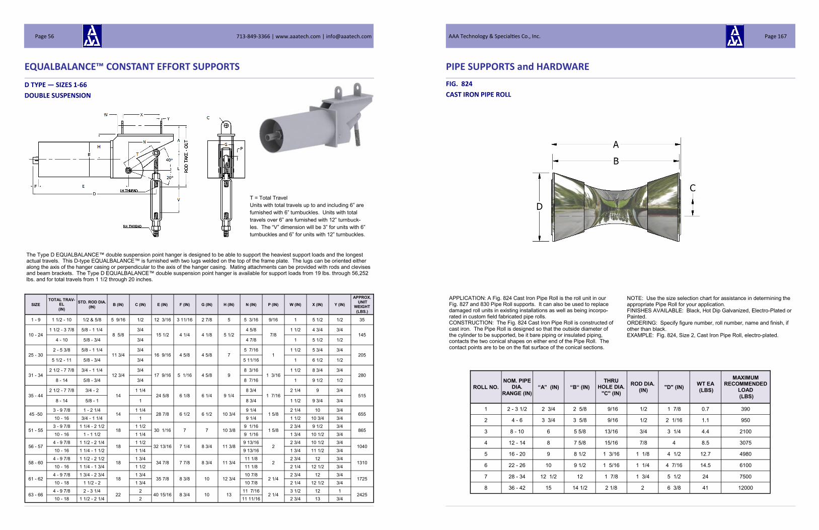
EQUALBALANCE™ CONSTANT EFFORT SUPPORTS
SIZE
TOTAL TRAV-EL
(IN)
STD. ROD DIA.
(IN) B (IN) C (IN) E (IN) F (IN) G (IN) H (IN) N (IN) P (IN) W (IN) X (IN) Y (IN)
APPROX. UNIT
WEIGHT
(LBS.)
1 - 9 1 1/2 - 10 1/2 & 5/8 5 9/16 1/2 12 3/16 3 11/16 2 7/8 5 5 3/16 9/16 1 5 1/2 1/2 35
10 - 24 1 1/2 - 3 7/8 5/8 - 1 1/4
8 5/8 3/4
15 1/2 4 1/4 4 1/8 5 1/2 4 5/8
7/8 1 1/2 4 3/4 3/4
145 4 - 10 5/8 - 3/4 3/4 4 7/8 1 5 1/2 1/2
25 - 30 2 - 5 3/8 5/8 - 1 1/4
11 3/4 3/4
16 9/16 4 5/8 4 5/8 7 5 7/16
1 1 1/2 5 3/4 3/4
205 5 1/2 - 11 5/8 - 3/4 3/4 5 11/16 1 6 1/2 1/2
31 - 34 2 1/2 - 7 7/8 3/4 - 1 1/4
12 3/4 3/4
17 9/16 5 1/16 4 5/8 9 8 3/16
1 3/16 1 1/2 8 3/4 3/4
280 8 - 14 5/8 - 3/4 3/4 8 7/16 1 9 1/2 1/2
35 - 44 2 1/2 - 7 7/8 3/4 - 2
14 1 1/4
24 5/8 6 1/8 6 1/4 9 1/4 8 3/4
1 7/16 2 1/4 9 3/4
515 8 - 14 5/8 - 1 1 8 3/4 1 1/2 9 3/4 3/4
45 -50 3 - 9 7/8 1 - 2 1/4
14 1 1/4
28 7/8 6 1/2 6 1/2 10 3/4 9 1/4
1 5/8 2 1/4 10 3/4
655 10 - 16 3/4 - 1 1/4 1 9 1/4 1 1/2 10 3/4 3/4
51 - 55 3 - 9 7/8 1 1/4 - 2 1/2
18 1 1/2
30 1/16 7 7 10 3/8 9 1/16
1 5/8 2 3/4 9 1/2 3/4
865 10 - 16 1 - 1 1/2 1 1/4 9 1/16 1 3/4 10 1/2 3/4
56 - 57 4 - 9 7/8 1 1/2 - 2 1/4
18 1 1/2
32 13/16 7 1/4 8 3/4 11 3/8 9 13/16
2 2 3/4 10 1/2 3/4
1040 10 - 16 1 1/4 - 1 1/2 1 1/4 9 13/16 1 3/4 11 1/2 3/4
58 - 60 4 - 9 7/8 1 1/2 - 2 1/2
18 1 3/4
34 7/8 7 7/8 8 3/4 11 3/4 11 1/8
2 2 3/4 12 3/4
1310 10 - 16 1 1/4 - 1 3/4 1 1/2 11 1/8 2 1/4 12 1/2 3/4
61 - 62 4 - 9 7/8 1 3/4 - 2 3/4
18 1 3/4
35 7/8 8 3/8 10 12 3/4 10 7/8
2 1/4 2 3/4 12 3/4
1725 10 - 18 1 1/2 - 2 1 3/4 10 7/8 2 1/4 12 1/2 3/4
63 - 66 4 - 9 7/8 2 - 3 1/4
22 2
40 15/16 8 3/4 10 13 11 7/16
2 1/4 3 1/2 12 1
2425 10 - 18 1 1/2 - 2 1/4 2 11 11/16 2 3/4 13 3/4
D TYPE — SIZES 1-66
DOUBLE SUSPENSION
The Type D EQUALBALANCE™ double suspension point hanger is designed to be able to support the heaviest support loads and the longest actual travels. This D-type EQUALBALANCE™ is furnished with two lugs welded on the top of the frame plate. The lugs can be oriented either along the axis of the hanger casing or perpendicular to the axis of the hanger casing. Mating attachments can be provided with rods and clevises and beam brackets. The Type D EQUALBALANCE™ double suspension point hanger is available for support loads from 19 lbs. through 56,252 lbs. and for total travels from 1 1/2 through 20 inches.
T = Total Travel
Units with total travels up to and including 6” are
furnished with 6” turnbuckles. Units with total
travels over 6” are furnished with 12” turnbuck-
les. The “V” dimension will be 3” for units with 6”
turnbuckles and 6” for units with 12” turnbuckles.
713-849-3366 | www.aaatech.com | [email protected] Page 56
PIPE SUPPORTS and HARDWARE
FIG. 824
CAST IRON PIPE ROLL
APPLICATION: A Fig. 824 Cast Iron Pipe Roll is the roll unit in our Fig. 827 and 830 Pipe Roll supports. It can also be used to replace damaged roll units in existing installations as well as being incorpo-rated in custom field fabricated pipe rolls. CONSTRUCTION: The Fig. 824 Cast Iron Pipe Roll is constructed of cast iron. The Pipe Roll is designed so that the outside diameter of the cylinder to be supported, be it bare piping or insulated piping, contacts the two conical shapes on either end of the Pipe Roll. The contact points are to be on the flat surface of the conical sections.
NOTE: Use the size selection chart for assistance in determining the appropriate Pipe Roll for your application. FINISHES AVAILABLE: Black, Hot Dip Galvanized, Electro-Plated or Painted. ORDERING: Specify figure number, roll number, name and finish, if other than black. EXAMPLE: Fig. 824, Size 2, Cast Iron Pipe Roll, electro-plated.
ROLL NO.
NOM. PIPE DIA.
RANGE (IN) “A” (IN) “B“ (IN)
THRU HOLE DIA.
"C" (IN)
ROD DIA.
(IN) "D" (IN)
WT EA
(LBS)
MAXIMUM RECOMMENDED
LOAD
(LBS)
1 2 - 3 1/2 2 3/4 2 5/8 9/16 1/2 1 7/8 0.7 390
2 4 - 6 3 3/4 3 5/8 9/16 1/2 2 1/16 1.1 950
3 8 - 10 6 5 5/8 13/16 3/4 3 1/4 4.4 2100
4 12 - 14 8 7 5/8 15/16 7/8 4 8.5 3075
5 16 - 20 9 8 1/2 1 3/16 1 1/8 4 1/2 12.7 4980
6 22 - 26 10 9 1/2 1 5/16 1 1/4 4 7/16 14.5 6100
7 28 - 34 12 1/2 12 1 7/8 1 3/4 5 1/2 24 7500
8 36 - 42 15 14 1/2 2 1/8 2 6 3/8 41 12000
AAA Technology & Specialties Co., Inc. Page 167
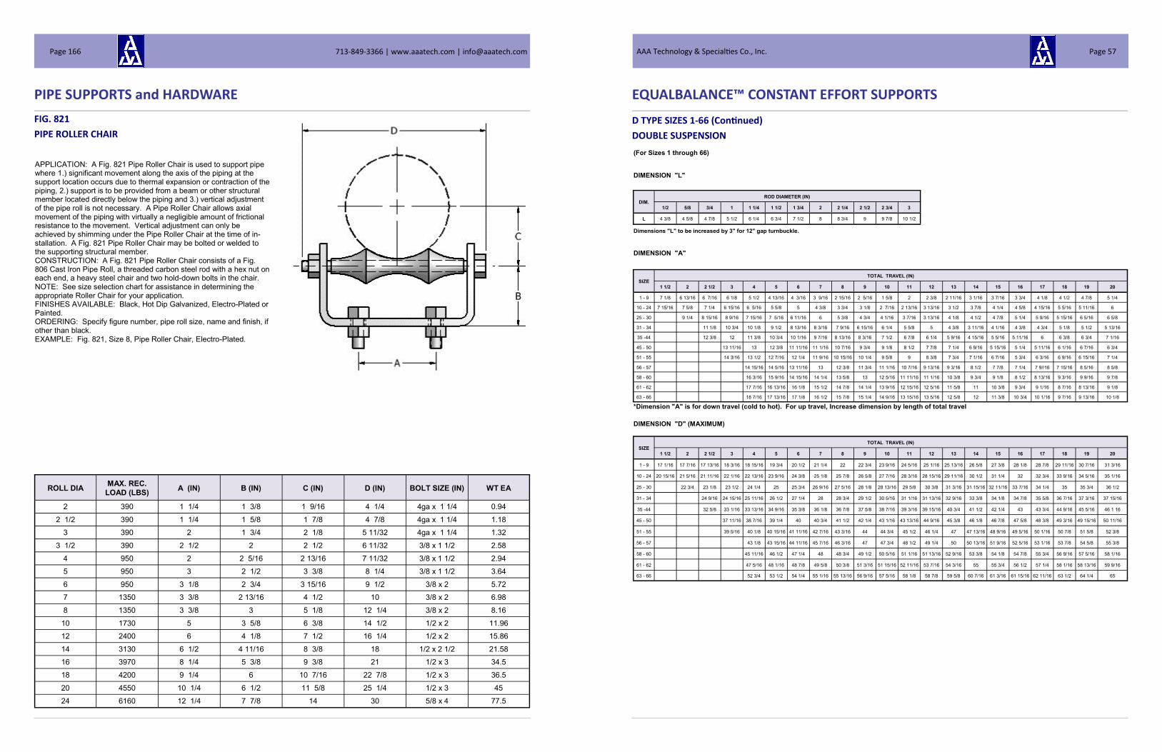
PIPE SUPPORTS and HARDWARE
FIG. 821
PIPE ROLLER CHAIR
APPLICATION: A Fig. 821 Pipe Roller Chair is used to support pipe where 1.) significant movement along the axis of the piping at the support location occurs due to thermal expansion or contraction of the piping, 2.) support is to be provided from a beam or other structural member located directly below the piping and 3.) vertical adjustment of the pipe roll is not necessary. A Pipe Roller Chair allows axial movement of the piping with virtually a negligible amount of frictional resistance to the movement. Vertical adjustment can only be achieved by shimming under the Pipe Roller Chair at the time of in-stallation. A Fig. 821 Pipe Roller Chair may be bolted or welded to the supporting structural member. CONSTRUCTION: A Fig. 821 Pipe Roller Chair consists of a Fig. 806 Cast Iron Pipe Roll, a threaded carbon steel rod with a hex nut on each end, a heavy steel chair and two hold-down bolts in the chair. NOTE: See size selection chart for assistance in determining the appropriate Roller Chair for your application. FINISHES AVAILABLE: Black, Hot Dip Galvanized, Electro-Plated or Painted. ORDERING: Specify figure number, pipe roll size, name and finish, if other than black. EXAMPLE: Fig. 821, Size 8, Pipe Roller Chair, Electro-Plated.
ROLL DIA MAX. REC.
LOAD (LBS) A (IN) B (IN) C (IN) D (IN) BOLT SIZE (IN) WT EA
2 390 1 1/4 1 3/8 1 9/16 4 1/4 4ga x 1 1/4 0.94
2 1/2 390 1 1/4 1 5/8 1 7/8 4 7/8 4ga x 1 1/4 1.18
3 390 2 1 3/4 2 1/8 5 11/32 4ga x 1 1/4 1.32
3 1/2 390 2 1/2 2 2 1/2 6 11/32 3/8 x 1 1/2 2.58
4 950 2 2 5/16 2 13/16 7 11/32 3/8 x 1 1/2 2.94
5 950 3 2 1/2 3 3/8 8 1/4 3/8 x 1 1/2 3.64
6 950 3 1/8 2 3/4 3 15/16 9 1/2 3/8 x 2 5.72
7 1350 3 3/8 2 13/16 4 1/2 10 3/8 x 2 6.98
8 1350 3 3/8 3 5 1/8 12 1/4 3/8 x 2 8.16
10 1730 5 3 5/8 6 3/8 14 1/2 1/2 x 2 11.96
12 2400 6 4 1/8 7 1/2 16 1/4 1/2 x 2 15.86
14 3130 6 1/2 4 11/16 8 3/8 18 1/2 x 2 1/2 21.58
16 3970 8 1/4 5 3/8 9 3/8 21 1/2 x 3 34.5
18 4200 9 1/4 6 10 7/16 22 7/8 1/2 x 3 36.5
20 4550 10 1/4 6 1/2 11 5/8 25 1/4 1/2 x 3 45
24 6160 12 1/4 7 7/8 14 30 5/8 x 4 77.5
713-849-3366 | www.aaatech.com | [email protected] Page 166
EQUALBALANCE™ CONSTANT EFFORT SUPPORTS
D TYPE SIZES 1-66 (Continued)
DOUBLE SUSPENSION
(For Sizes 1 through 66)
DIMENSION "L"
DIM. ROD DIAMETER (IN)
1/2 5/8 3/4 1 1 1/4 1 1/2 1 3/4 2 2 1/4 2 1/2 2 3/4 3
L 4 3/8 4 5/8 4 7/8 5 1/2 6 1/4 6 3/4 7 1/2 8 8 3/4 9 9 7/8 10 1/2
Dimensions "L" to be increased by 3" for 12" gap turnbuckle.
DIMENSION "A"
SIZE TOTAL TRAVEL (IN)
1 1/2 2 2 1/2 3 4 5 6 7 8 9 10 11 12 13 14 15 16 17 18 19 20
1 - 9 7 1/8 6 13/16 6 7/16 6 1/8 5 1/2 4 13/16 4 3/16 3 9/16 2 15/16 2 5/16 1 5/8 2 2 3/8 2 11/16 3 1/16 3 7/16 3 3/4 4 1/8 4 1/2 4 7/8 5 1/4
10 - 24 7 15/16 7 5/8 7 1/4 6 15/16 6 5/16 5 5/8 5 4 3/8 3 3/4 3 1/8 2 7/16 2 13/16 3 13/16 3 1/2 3 7/8 4 1/4 4 5/8 4 15/16 5 5/16 5 11/16 6
25 - 30 9 1/4 8 15/16 8 9/16 7 15/16 7 5/16 6 11/16 6 5 3/8 4 3/4 4 1/16 3 7/16 3 13/16 4 1/8 4 1/2 4 7/8 5 1/4 5 9/16 5 15/16 6 5/16 6 5/8
31 - 34 11 1/8 10 3/4 10 1/8 9 1/2 8 13/16 8 3/16 7 9/16 6 15/16 6 1/4 5 5/8 5 4 3/8 3 11/16 4 1/16 4 3/8 4 3/4 5 1/8 5 1/2 5 13/16
35 -44 12 3/8 12 11 3/8 10 3/4 10 1/16 9 7/16 8 13/16 8 3/16 7 1/2 6 7/8 6 1/4 5 9/16 4 15/16 5 5/16 5 11/16 6 6 3/8 6 3/4 7 1/16
45 - 50 13 11/16 13 12 3/8 11 11/16 11 1/16 10 7/16 9 3/4 9 1/8 8 1/2 7 7/8 7 1/4 6 9/16 5 15/16 5 1/4 5 11/16 6 1/16 6 7/16 6 3/4
51 - 55 14 3/16 13 1/2 12 7/16 12 1/4 11 9/16 10 15/16 10 1/4 9 5/8 9 8 3/8 7 3/4 7 1/16 6 7/16 5 3/4 6 3/16 6 9/16 6 15/16 7 1/4
56 - 57 14 15/16 14 5/16 13 11/16 13 12 3/8 11 3/4 11 1/16 10 7/16 9 13/16 9 3/16 8 1/2 7 7/8 7 1/4 7 9//16 7 15/16 8 5/16 8 5/8
58 - 60 16 3/16 15 9/16 14 15/16 14 1/4 13 5/8 13 12 5/16 11 11/16 11 1/16 10 3/8 9 3/4 9 1/8 8 1/2 8 13/16 9 3/16 9 9/16 9 7/8
61 - 62 17 7/16 16 13/16 16 1/8 15 1/2 14 7/8 14 1/4 13 9/16 12 15/16 12 5/16 11 5/8 11 10 3/8 9 3/4 9 1/16 8 7/16 8 13/16 9 1/8
63 - 66 18 7/16 17 13/16 17 1/8 16 1/2 15 7/8 15 1/4 14 9/16 13 15/16 13 5/16 12 5/8 12 11 3/8 10 3/4 10 1/16 9 7/16 9 13/16 10 1/8
*Dimension "A" is for down travel (cold to hot). For up travel, Increase dimension by length of total travel
DIMENSION "D" (MAXIMUM)
SIZE TOTAL TRAVEL (IN)
1 1/2 2 2 1/2 3 4 5 6 7 8 9 10 11 12 13 14 15 16 17 18 19 20
1 - 9 17 1/16 17 7/16 17 13/16 18 3/16 18 15/16 19 3/4 20 1/2 21 1/4 22 22 3/4 23 9/16 24 5/16 25 1/16 25 13/16 26 5/8 27 3/8 28 1/8 28 7/8 29 11/16 30 7/16 31 3/16
10 - 24 20 15/16 21 5/16 21 11/16 22 1/16 22 13/16 23 9/16 24 3/8 25 1/8 25 7/8 26 5/8 27 7/16 28 3/16 28 15/16 29 11/16 30 1/2 31 1/4 32 32 3/4 33 9/16 34 5/16 35 1/16
25 - 30 22 3/4 23 1/8 23 1/2 24 1/4 25 25 3/4 26 9/16 27 5/16 28 1/8 28 13/16 29 5/8 30 3/8 31 3/16 31 15/16 32 11/16 33 7/16 34 1/4 35 35 3/4 36 1/2
31 - 34 24 9/16 24 15/16 25 11/16 26 1/2 27 1/4 28 28 3/4 29 1/2 30 5/16 31 1/16 31 13/16 32 9/16 33 3/8 34 1/8 34 7/8 35 5/8 36 7/16 37 3/16 37 15/16
35 -44 32 5/8 33 1/16 33 13/16 34 9/16 35 3/8 36 1/8 36 7/8 37 5/8 38 7/16 39 3/16 39 15/16 40 3/4 41 1/2 42 1/4 43 43 3/4 44 9/16 45 5/16 46 1 16
45 - 50 37 11/16 38 7/16 39 1/4 40 40 3/4 41 1/2 42 1/4 43 1/16 43 13/16 44 9/16 45 3/8 46 1/8 46 7/8 47 5/8 48 3/8 49 3/16 49 15/16 50 11/16
51 - 55 39 5/16 40 1/8 40 15/16 41 11/16 42 7/16 43 3/16 44 44 3/4 45 1/2 46 1/4 47 47 13/16 48 9/16 49 5/16 50 1/16 50 7/8 51 5/8 52 3/8
56 - 57 43 1/8 43 15/16 44 11/16 45 7/16 46 3/16 47 47 3/4 48 1/2 49 1/4 50 50 13/16 51 9/16 52 5/16 53 1/16 53 7/8 54 5/8 55 3/8
58 - 60 45 11/16 46 1/2 47 1/4 48 48 3/4 49 1/2 50 5/16 51 1/16 51 13/16 52 9/16 53 3/8 54 1/8 54 7/8 55 3/4 56 9/16 57 5/16 58 1/16
61 - 62 47 5/16 48 1/16 48 7/8 49 5/8 50 3/8 51 3/16 51 15/16 52 11/16 53 7/16 54 3/16 55 55 3/4 56 1/2 57 1/4 58 1/16 58 13/16 59 9/16
63 - 66 52 3/4 53 1/2 54 1/4 55 1/16 55 13/16 56 9/16 57 5/16 58 1/8 58 7/8 59 5/8 60 7/16 61 3/16 61 15/16 62 11/16 63 1/2 64 1/4 65
AAA Technology & Specialties Co., Inc. Page 57

EQUALBALANCE™ CONSTANT EFFORT SUPPORTS
D TYPE — SIZES 67-74
DOUBLE SUSPENSION
DIMENSION "L"
DIM. ROD DIA. (IN)
1 1/4 1 1/2 1 3/4 2 2 1/4 2 1/2 2 3/4 3 3 1/4 3 1/2 3 3/4 4
L 6 1/4 6 3/4 7 1/2 8 8 3/4 9 9 7/8 10 1/2 11 1/2 11 3/4 12 1/2 13 1/4
Dimensions "L" to be increased by 3" for 12" gap turnbuckle.
Rod Take-out = L + A*
DIMENSION "A"
SIZE TOTAL TRAVEL (IN)
6 7 8 9 10 11 12 13 14 15 16 17 18 19 20
67 - 70 19 3/8 18 3/4 18 1/8 17 1/2 16 13/16 16 3/16 15 9/16 14 7/8 14 1/4 13 5/8 13 12 5/16 11 11/16 11 1/16 10 3/8
71 - 72 20 5/8 20 19 3/8 18 3/4 18 1/16 17 7/16 16 3/4 16 1/8 15 1/2 14 7/8 14 1/4 13 9/16 12 15/16 12 5/16
73 - 74 21 3/4 21 1/8 20 1/2 19 13/16 19 3/16 18 9/16 17 15/16 17 1/4 16 5/8 16 15 3/8 14 11/16 14 1/16 13 7/16 12 3/4
Dimensions "A" is for down travel (cold to hot). For up travel, increase dimension by length of total travel.
DIMENSION "C" DIMENSION "I" AND "N"
SIZE TOTAL TRAVEL (IN)
DIM. TOTAL TRAVEL (IN)
6 - 15 16 17 18 19 20 6 - 15 16 17 18 19 20
67 - 70 14 3/8 15 3/8 16 3/8 17 3/8 18 3/8 19 3/8 I 14 7/8 15 7/8 16 7/8 17 7/8 18 7/8 19 7/8
N 13 15/16 14 15/16 15 15/16 16 15/16 17 15/16 18 15/16
71 - 72 15 3/8 16 3/8 17 3/8 18 3/8 19 3/8 20 3/8 I 14 7/8 15 7/8 16 7/8 17 7/8 18 7/8 19 7/8
N 14 3/16 15 3/16 16 3/16 17 3/16 18 3/16 19 3/16
73 - 74 16 3/8 17 3/8 18 3/8 19 3/8 20 3/8 21 3/8 I 14 7/8 15 7/8 16 7/8 17 7/8 18 7/8 19 7/8
N 14 13/16 15 13/16 16 13/16 17 13/16 18 13/16 19 13/16
SIZE
TOTAL TRAVEL
(IN)
STD. ROD
DIA. (IN) B (IN) E (IN) F (IN) G (IN) H (IN) J (IN) P (IN) Q (IN) U (IN) W (IN)
APPROX. UNIT WT
(LBS.)
67 6 - 20 1 3/4 - 3 22 46 1/4 9 1/2 10 7/16 2 1/8 3/4 2 1/4 2 1/2 1 3/4 7 2475
68 6 - 20 1 3/4 - 3 22 47 9 1/2 10 7/16 2 1/8 3/4 2 1/4 2 1/2 1 3/4 7 2500
69 6 - 20 1 3/4 - 3 1/4 22 50 9 1/2 10 7/16 2 1/8 3/4 2 1/4 2 1/2 1 3/4 7 2550
70 6 - 20 2 - 3 1/2 20 51 1/8 9 1/2 10 7/16 2 1/8 3/4 2 1/4 2 1/2 1 3/4 7 2565
71 6 - 20 2 - 3 1/2 20 55 1/8 9 7/8 12 9/16 2 3/8 1 2 1/2 3 2 1/4 8 7/16 3180
72 6 - 20 2 - 3 3/4 18 58 1/4 9 7/8 12 9/16 2 3/8 1 2 1/2 3 2 1/4 8 7/16 3380
73 6 - 20 2 1/4 - 4 18 53 3/8 10 5/8 12 9/16 2 5/8 1 2 5/8 3 2 1/4 8 7/16 3800
74 6 - 20 2 1/4 - 4 24 54 5/8 10 5/8 12 9/16 2 5/8 1 2 5/8 3 2 1/4 8 7/16 4500
T = Total Travel
Units with total travels up to and including 6” are
furnished with 6” turnbuckles. Units with total
travels over 6” are furnished with 12” turnbuckles.
The “V” dimension will be 3” for units with 6” turn-
buckles and 6” for units with 12” turnbuckles.
713-849-3366 | www.aaatech.com | [email protected] Page 58
PIPE SUPPORTS and HARDWARE
FIG. 818
ALTERNATE ADJUSTABLE PIPE ROLLER
APPLICATION: A Fig. 818 Alternate Adjustable Support Roller is used to support piping where 1.) significant movement along the axis of the piping at the support location occurs due to thermal expansion or contraction of the piping, 2.) support is to be provided from a beam or other structural member located immediately below the piping and 3.) limited vertical adjustment of the pipe roll is necessary or desira-ble. An Alternate Adjustable Support Roller allows axial movement of the piping with virtually a negligible amount of frictional resistance to the movement. Vertical adjustment is achieved by changing the ele-vation of the adjustment nuts above and below the structural member to which the support rods are attached. Vertical adjustment is limited to the threads on the support rods. CONSTRUCTION: A Fig. 818 Alternate Adjustable Support Roller consists of a Fig. 806 Cast Iron Pipe Roll, a carbon steel roll rod bent on both ends to provide vertical legs for support and four nuts. NOTE: See size selection chart for assistance in determining the appropriate Alternate Adjustable Support Roller for your application. FINISHES AVAILABLE: Black, Hot Dip Galvanized, Electro-Plated or Painted. ORDERING: Specify figure number, pipe roll size, name and finish, of other than black. EXAMPLE: Fig. 818, Size 4, Alternate Adjustable Support Roller,
ROLL DIA MAX. REC.
LOAD (LBS) A (IN) B (IN) C (IN) D (IN)
ROLLER
LENGTH (IN) WT EA
2 300 4 1/2 3/8 4 1/2 2 5/8 1 5/8 0.6
2 1/2 600 5 1/2 4 1/2 3 1/8 1 15/16 0.95
3 600 6 1/8 1/2 4 1/2 6 3/4 2 1/4 1.2
3 1/2 600 6 1/2 1/2 4 1/2 4 1/4 2 9/16 1.3
4 700 7 3/8 1/2 4 1/2 4 3/4 2 13/16 1.5
5 700 8 1/2 5/8 4 1/2 5 13/16 3 7/16 2.8
6 1000 10 3/4 4 1/2 6 7/8 4 1/16 4.235
8 1300 12 7/8 5 1/4 8 7/8 5 1/8 6.3
10 1700 14 7/8 5 1/2 11 6 3/8 10
12 2300 16 7/8 6 13 7 5/16 12.7
14 3075 17 1/2 1 1/8 7 14 1/4 8 5/16 22
16 3075 19 1 1/4 8 16 1/4 9 1/2 28
AAA Technology & Specialties Co., Inc. Page 165

PIPE SUPPORTS and HARDWARE
FIG. 815
ADJUSTABLE SUPPORT ROLLER
ROLL DIA MAX. REC.
LOAD (LBS) A (IN) B (IN) C (IN) D (IN) H (IN) WT EA
2 600 3/8 4 3/8 2 7/8 12 1 9/16 1.45
2 1/2 600 1/2 5 1/8 3 1/8 12 1 7/8 2.535
3 700 1/2 5 5/8 3 3/4 12 2 1/8 2.735
3 1/2 750 1/2 5 7/8 3 7/8 12 2 1/2 2.85
4 750 1/2 7 4 3/4 12 2 13/16 4.32
5 750 5/8 8 1/8 5 3/4 12 3 3/8 4.78
6 1070 3/4 9 3/4 6 7/8 12 3 15/16 7.705
7 1070 3/4 10 1/2 8 12 4 1/2 8.41
8 1350 7/8 12 1/8 8 7/8 12 5 1/8 12.205
10 1730 7/8 14 11 12 3 1/4 13.95
12 2400 7/8 15 3/4 13 12 7 5/16 17.93
14 3130 1 1/8 17 3/4 14 1/4 18 8 3/8 27.545
16 3970 1 1/4 20 9/16 16 7/8 18 9 1/2 33.34
18 4200 1 1/4 22 18 5/16 18 10 7/16 36
20 4550 1 1/4 24 200 1/4 18 11 1/2 46.6
24 6160 1 1/2 28 3/4 24 1/4 24 13 13/16 81.22
30 7290 1 3/4 35 5/8 30 1/4 24 17 1/4 109.22
APPLICATION: A Fig. 815 Adjustable Support Roller is used to sup-port piping where 1.) significant movement along the axis of the pip-ing at the support location occurs due to thermal expansion or con-traction of the piping, 2.) support is to be provided from a beam or other structural member located below the piping and 3.) significant vertical adjustment of the pipe roll is necessary or desirable. An Ad-justable Support Roller allows axial movement of the piping with virtu-ally a negligible amount of frictional resistance to the movement. Vertical adjustment is achieved by changing the elevation of the ad-justment nuts above and below the structural member to which the support rods are attached. CONSTRUCTION: A Fig. 815 Adjustable Support Roller consists of a Fig. 806 Cast Iron Pipe Roll, two cast iron sockets, one on each end as shown in the picture, a carbon steel roll rod, two pieces of all thread rod (length = “D” dimension) and eight nuts. NOTE: See size selection chart for assistance in determining the appropriate Adjustable Support Roller for your application. FINISHES AVAILABLE: Black, Hot Dip Galvanized, Electro-Plated or Painted. ORDERING: Specify figure number, pipe roll size, name and finish, if other than black. EXAMPLE: Fig. 815, Size 8, Adjustable Support Roller, HDG.
713-849-3366 | www.aaatech.com | [email protected] Page 164
EQUALBALANCE™ CONSTANT EFFORT SUPPORTS
D TYPE—SIZES 67-74 (Continued)
DOUBLE SUSPENSION
Rod Take-out = A* - K
SIZE
TOTAL TRAVEL
(IN)
STD. ROD
DIA. (IN) B (IN) E (IN) F (IN) G (IN) H(IN) J (IN) K (IN) M (IN) Q (IN) U (IN) Z (IN)
APPROX. UNIT WT
(LBS.)
75 7 - 20 2 1/2 - 4 23 15/16 47 9 1/2 27 3 5/8 1 1/4
3 x Rod Dia.
(Min.)
18 5 2 3/4 5 5300
76 7 - 20 2 1/2 - 4 1/4 23 15/16 50 9 1/2 27 3 5/8 1 1/4 18 5 2 3/4 5 5700
77 7 1/2 - 20 2 3/4 - 4 1/4 23 15/16 51 1/8 9 1/2 27 3 5/8 1 1/4 18 5 2 3/4 5 5720
78 8 - 20 2 3/4 - 4 1/4 23 15/16 55 1/8 9 7/8 27 3 5/8 1 1/4 16 5 2 3/4 5 5800
79 9 - 20 3 - 4 1/4 23 15/16 58 1/4 9 7/8 27 3 5/8 1 1/4 16 5 2 3/4 5 6400
80 10 - 20 3 1/4 - 4 1/4 23 15/16 53 3/8 10 5/8 27 3 5/8 1 1/4 16 5 2 3/4 5 6670
81 11 - 20 3 1/4 - 4 1/4 26 15/16 54 5/8 10 5/8 30 3 5/8 1 1/2 19 5 2 3/4 5 6950
DIMENSION "D" (MAXIMUM)
SIZE TOTAL TRAVEL (IN)
6 7 8 9 10 11 12 13 14 15 16 17 18 19 20
67 60 3/8 61 1/8 61 7/8 62 5/8 63 7/16 64 3/16 64 15/16 65 11/16 66 1/2 67 1/4 68 68 3/4 69 1/2 70 5/16 71 1/16
68 61 1/8 61 7/8 62 5/8 63 3/8 64 3/16 64 15/16 65 11/16 66 1/2 67 1/4 68 68 3/4 69 1/2 70 5/16 71 1/16 71 13/16
69 64 1/8 64 7/8 65 5/8 66 3/8 67 3/16 67 15/16 68 11/16 69 1/2 70 1/4 71 71 3/4 72 1/2 73 5/16 74 1/16 74 13/16
70 65 1/4 66 66 3/4 67 1/2 68 5/16 69 1/16 69 13/16 70 9/16 71 3/8 72 1/8 72 7/8 73 5/8 74 7/16 75 3/16 75 15/16
71 69 9/16 70 3/8 71 1/8 71 7/8 72 11/16 73 7/16 74 3/16 74 15/16 75 3/4 76 1/2 77 1/4 78 78 3/4 79 9/16 80 1/4
72 72 11/16 73 1/2 74 1/4 75 75 3/4 76 9/16 77 5/16 78 1/16 78 13/16 79 9/16 80 3/8 81 1/8 81 7/8 82 11/16 83 7/16
73 68 9/16 69 3/8 70 1/8 70 7/8 71 5/8 72 7/16 73 3/16 73 15/16 74 11/16 75 1/2 76 1/4 77 77 3/4 78 9/16 79 5/16
74 69 7/8 70 5/8 71 3/8 72 1/8 72 15/16 73 11/16 74 7/16 75 3/16 76 76 3/4 77 1/2 78 1/4 79 1/16 79 13/16 80 9/16
D TYPE—SIZES 75-81
DOUBLE SUSPENSION
T = Total Travel
Units with total travels up to and including 6” are
furnished with 6” turnbuckles. Units with total
travels over 6” are furnished with 12” turnbuckles.
The “V” dimension will be 3” for units with 6” turn-
buckles and 6” for units with 12” turnbuckles.
AAA Technology & Specialties Co., Inc. Page 59

EQUALBALANCE™ CONSTANT EFFORT SUPPORTS
DIMENSION "C" DIMENSION "I" AND "N"
SIZE
TOTAL TRAVEL
DIM.
TOTAL TRAVEL
MIN. TO
15 16 17 18 19 20
MIN. TO
15 16 17 18 19 20
75 - 77 17 7/8 18 7/8 19 7/8 20 7/8 21 7/8 22 7/8 I 14 7/8 15 7/8 16 7/8 17 7/8 18 7/8 19 7/8
N 13 7/8 14 7/8 15 7/8 16 7/8 17 7/8 18 7/8
78 - 79 18 7/8 19 7/8 20 7/8 21 7/8 22 7/8 23 7/8 I 14 7/8 15 7/8 16 7/8 17 7/8 18 7/8 19 7/8
N 13 5/8 14 5/8 15 5/8 16 5/8 17 5/8 18 5/8
80 - 81 19 7/8 20 7/8 21 7/8 22 7/8 23 7/8 24 7/8 I 14 7/8 15 7/8 16 7/8 17 7/8 18 7/8 19 7/8
N 13 5/8 14 5/8 15 5/8 16 5/8 17 5/8 18 5/8
For travels over 15", dimensions "I" & "N" are approximate. These dimensions will vary to match the top connections.
DIMENSION "A"
SIZE
TOTAL TRAVEL (IN)
7 8 9 10 11 12 13 14 15 16 17 18 19 20
75 31 29 1/4 27 1/4 26 1/2 26 25 1/4 24 3/4 24 21 3/4 22 1/4 22 9/16 22 15/16 23 3/4 24 1/8
76 31 27 3/4 26 3/4 26 1/2 25 1/2 25 1/4 24 3/4 24 21 1/4 22 1/4 22 9/16 22 15/16 23 1/4 23 5/8
77 31 27 3/4 26 3/4 26 25 1/2 24 3/4 24 3/4 24 21 1/4 20 3/4 22 9/16 22 15/16 23 1/4 23 5/8
78 32 1/4 30 3/4 30 1/2 29 28 1/4 28 1/4 27 1/2 25 1/4 24 3/4 25 1/16 25 7/16 25 3/4 26 1/8
79 30 3/4 30 30 28 3/4 27 3/4 27 1/2 25 3/4 24 1/4 25 1/16 25 7/16 25 3/4 26 1/8
80 32 31 1/2 30 1/4 29 3/4 29 27 3/4 27 1/4 27 9/16 26 15/16 27 1/4 27 5/8
81 30 1/2 29 3/4 29 1/4 29 28 1/4 26 3/4 27 9/16 27 15/16 28 1/4 27 5/8
Dimension "A" is for down travel (cold to hot). For up travel, increase dimension by length of total travel.
DIMENSION "D"
SIZE
TOTAL TRAVEL (IN)
7 8 9 10 11 12 13 14 15 16 17 18 19 20
75 61 7/8 62 5/8 63 3/8 64 3/16 64 15/16 65 11/16 66 7/16 67 1/4 68 68 3/4 69 1/2 70 5/16 71 1/16 71 13/16
76 64 7/8 65 5/8 66 3/8 67 3/16 67 15//16 68 11/16 69 7/16 70 1/4 71 71 3/4 72 1/2 73 5/16 74 1/16 74 13/16
77 66 3/4 67 1/2 68 5/16 69 1/16 69 13/16 70 9/16 71 3/8 72 1/8 72 7/8 73 5/16 74 7/16 75 3/16 75 15/16
78 71 1/8 71 7/8 72 5/8 73 7/16 74 3/16 74 15/16 75 3/4 76 1/2 77 1/4 78 78 13/16 79 9/16 80 5/16
79 75 75 3/4 76 9/16 77 5/16 78 1/16 78 13/16 79 5/8 80 3/8 81 1/8 81 7/8 82 5/8 83 7/16
80 71 5/8 72 7/16 73 3/16 73 15/16 74 3/4 75 1/2 76 1/4 77 77 3/4 78 9/16 79 5/16
81 73 11/16 74 7/16 75 3/16 76 76 3/4 77 1/2 78 1/4 79 1/16 79 13/16 80 9/16
D TYPE—SIZES 75-81 (Continued)
DOUBLE SUSPENSION
DIMENSION "Y"
ROD DIA. 2 1/2 2 3/4 3 3 1/4 3 1/2 3 3/4 4 4 1/4
75 - 80 8 8 9 9 10 10 11 11
81 8 1/2 8 1/2 9 1/2 9 1/2 11 11 12 12
713-849-3366 | www.aaatech.com | [email protected] Page 60
PIPE SUPPORTS and HARDWARE
FIG. 812
TWO ROD ROLL TYPE HANGER
ROLL DIA MAX. REC.
LOAD A (IN) B (IN) C (IN) D (IN) E (IN) F (IN) H (IN) J (IN) WT EA
2 600 3/8 4 3/8 5 5/8 2 7/8 5/8 3/8 1 9/16 3/4 0.76
2 1/2 660 1/2 5 1/8 6 1/2 3 1/8 7/8 1/2 1 7/8 7/8 1.185
3 700 1/2 5 5/8 7 3 3/4 7/8 1/2 2 1/8 7/8 1.385
3 1/2 750 1/2 5 7/8 7 1/4 3 7/8 7/8 1/2 2 1/2 7/8 1.5
4 750 5/8 7 8 9/16 4 3/4 7/8 1/2 2 13/16 1 2.11
5 750 5/8 8 1/8 9 3/4 5 3/4 7/8 5/8 3 3/8 1 1/8 2.57
6 1070 3/4 9 3/4 11 5/8 6 7/8 1 3/4 3 15/16 1 3/8 4.395
7 1070 3/4 10 1/2 12 1/2 8 1 3/4 4 1/2 1 5/8 5.16
8 1350 7/8 12 1/8 14 1/4 8 7/8 1 1/8 7/8 5 1/8 1 1/2 7.425
10 1730 7/8 14 16 1/4 11 1 1/8 7/8 6 1/4 1 3/4 9.17
12 2400 7/8 15 3/4 18 13 1 1/8 7/8 7 5/16 2 13.15
14 3130 1 17 3/4 20 1/2 14 1/4 1 3/8 1 8 3/8 2 5/8 18.745
16 3970 1 20 9/16 23 3/8 16 7/8 1 3/8 1 9 1/2 2 5/8 24.54
18 4200 1 22 14 7/8 18 5/16 1 3/8 1 10 7/16 2 3/4 27.2
20 4550 1 1/4 24 27 20 1/4 1 1/2 1 1/4 11 1/2 3 32
24 6160 1 1/2 28 3/4 32 24 1/4 1 3/4 1 1/4 13 13/16 3 5/8 54
30 7290 1 3/4 35 5/8 39 3/4 30 1/4 2 1/8 1 1/4 17 1/4 4 1/2 82
APPLICATION: A Fig. 812 Two Rod Roll Type Hanger is used to support piping where 1.) significant movement along the axis of the piping at the support location occurs due to thermal expansion or contraction of the piping, 2.) support is to be provided by two rods attached to a structural member above the pipe and 3.) substantial vertical adjustment of the pipe roll is necessary or desirable. A Roll Type Hanger allows axial movement of the piping with virtually a neg-ligible amount of frictional resistance to the movement. In addition, the support remains virtually vertical resulting in very little angular rotation of the support rod. Vertical adjustment is achieved by chang-ing the elevation of the adjustment nuts and is only limited by the amount of threading on the hanger rods. CONSTRUCTION: A Fig. 812 Two Rod Roll Type Hanger consists of a Fig. 806 Cast Iron Pipe Roll, two cast iron sockets, one on each end as shown in the picture, and a carbon steel roll rod. NOTE: See size selection chart for assistance in determining the appropriate Two Rod Roll Type Hanger for your application. FINISHES AVAILABLE: Black, Hot Dip Galvanized, Electro-Plated or Painted. ORDERING: Specify figure number, roll size, name and finish, if other than black. NOTE: Hanger rods and nuts are to be ordered separately. EXAMPLE: Fig. 812, Size 6, Two Rod Roll Type Hanger, HDG.
AAA Technology & Specialties Co., Inc. Page 163

PIPE SUPPORTS and HARDWARE
FIG. 809
CLEVIS ROLLER HANGER
APPLICATION: A Fig. 809 Clevis Roller Hanger is used to support piping where 1.) significant movement along the axis of the piping at the support location occurs due to thermal expansion or contraction of the piping, 2.) support is to be provided by one rod attached to the structural member above the piping, 3.) a limited amount of vertical adjustment of the pipe roll is necessary or desirable and 4.) the sup-port loads are relatively small. A Roller Hanger allows significant axial movement of the piping along the axis of the piping with virtually a negligible amount of frictional resistance to the movement. In addi-tion, the support remains virtually vertical resulting in very little angu-lar rotation of the support rod. Vertical adjustment is achieved by changing the elevation of the adjustment nuts above and below the top of the yoke and is limited to the distance between the pipe’s out-side surface and the bottom end of the hanger rod. CONSTRUCTION: A Fig. 809 Clevis Roller Hanger consists of a Fig. 806 Cast Iron Pipe Roll, a carbon steel yoke, a threaded carbon steel roll rod and hex nuts on each end of the roll rod. NOTE: See size selection chart for assistance in determining the appropriate Clevis Roller Hanger for your application. FINISHES AVAILABLE: Black, Hot Dip Galvanized, Electro-Plated or Painted. ORDERING: Specify figure number, roll size, name and finish, if other than black. NOTE: Hanger rod and nuts are to be ordered separately. EXAMPLE: Fig. 809, Size 4, Clevis Roller Hanger, Painted.
ROLL DIA MAX. REC.
LOAD (LBS) A (IN) B (IN) C (IN) F (IN) STEEL SIZE
ROLL ROD
DIA. (IN) WT EA
2 150 1/2 4 15/16 1 9/16 2 7/8 8ga x 1 1/4 3/8 1.14
2 1/2 225 1/2 5 13/16 1 7/8 3 1/4 8ga x 1 1/4 3/8 1.47
3 310 1/2 6 7/16 2 1/8 3 13/16 8ga x 1 1/4 1/2 1.62
3 1/2 390 1/2 7 1/8 2 1/2 4 5/16 3ga x 1 1/2 1/2 2.76
4 475 5/8 7 5/8 2 13/16 4 7/8 3ga x 1 1/2 1/2 3.16
5 685 5/8 9 1/8 3 3/8 5 7/8 3ga x 2 5/8 4.62
6 780 3/4 10 5/16 3 15/16 7 3ga x 2 3/4 6.08
7 780 3/4 10 13/16 4 1/2 8 3ga x 2 3/4 7.59
8 780 7/8 12 11/16 5 1/8 9 3/8 x 2 7/8 11.83
10 965 7/8 15 6 1/4 11 1/8 3/8 x 2 1/2 7/8 17.29
12 965 1 17 7 3/8 13 1/2 x 2 7/8 22.5
14 1200 1 1/8 19 5/8 8 3/8 14 1/4 1/2 x 2 1/2 7/8 33
16 1200 1 1/4 21 5/8 9 3/8 16 1/4 1/2 x 3 7/8 46
18 1400 1 1/4 23 3/4 10 1/2 18 1/4 1/2 x 3 7/8 50.5
20 1600 1 3/8 25 7/8 11 5/8 20 1/4 1/2 x 3 7/8 65
713-849-3366 | www.aaatech.com | [email protected] Page 162
EQUALBALANCE™ CONSTANT EFFORT SUPPORTS
B TYPE
HORIZONTAL BASE
The horizontal base Type B EQUALBALANCE™ hanger is designed for use in limited headroom applications where available structural support members are above and close to the pipe. The B-type EQUALBALANCE™ may be mounted on top of the supporting steel or inverted beneath the support steel in a trapeze arrangement. The load rod connection is a bushing or a spherical bearing if desired to permit the support rod to swing in both directions. The EQUALBALANCE™ Type B hanger is available for support loads from 26 lbs. through 90,627 lbs. and for total trav-els from 1 1/2 through 20 inches.
SIZE
TOTAL TRAVEL
J (IN)
STD. ROD
DIA. (IN) B (IN) C (IN) E (IN) F (IN) G (IN) H (IN) O (IN) M (IN) N (IN) X (IN)
APPROX. UNIT
WEIGHT
(LBS.)
1 - 9 1 1/2 - 20 1/2 & 5/8 5 9/16 4 5/8 12 3/16 3 11/16 2 7/8 9/16 4 1/4 2 1 5/16 1/4 40
10 - 24 2 - 20 1/2 - 1 8 5/8 6 15 1/2 4 1/4 4 1/8 9/16 5 3/4 2 1 5/8 3/8 120
25 - 30 3 - 20 5/8 - 1 11 3/4 7 1/2 16 9/16 4 5/8 4 5/8 9/16 6 1/4 2 1/2 1 13/16 3/8 220
31 - 34 3 - 20 5/8 - 1 1/4 12 3/4 8 3/8 17 9/16 5 1/16 4 5/8 13/16 7 2 1/2 2 1/16 3/8 275
35 - 44 4 - 20 5/8 - 1 1/2 14 8 1/2 24 5/8 6 1/8 6 1/4 13/16 8 1/2 3 2 1/2 1/2 475
45 - 50 4 - 20 3/4 - 1 3/4 14 9 28 7/8 6 1/2 6 1/2 13/16 8 3/4 3 3 1/2 540
51 - 55 4 - 20 1 - 2 18 10 5/8 30 1/16 7 7 13/16 9 1/4 4 3 3/16 5/8 825
56 - 57 5 - 20 1 1/4 - 2 18 11 1/2 32 13/16 7 1/4 8 7/8 1 1/16 12 1/2 4 3 7/16 3/4 1165
58 - 60 5 - 20 1 1/4 - 2 1/4 18 11 5/8 34 7/8 7 7/8 8 7/8 1 1/16 12 1/2 4 1/2 3 5/8 3/4 1500
61 - 62 6 - 20 1 1/2 - 2 1/4 18 12 7/8 35 7/8 8 3/8 10 1 1/16 13 1/2 4 1/2 3 7/8 1 1550
63 - 66 6 - 20 1 1/2 - 2 3/4 22 13 3/4 40 15/16 8 3/4 10 1 1/16 13 1/2 5 4 1/16 1 2175
67 6 - 20 2 - 3 22 14 46 1/4 9 1/2 10 1/2 1 1/16 13 1/2 5 4 3/8 1 2475
68 6 - 20 2 - 3 1/4 22 14 47 9 1/2 10 1/2 1 1/16 13 1/2 5 4 3/8 1 2500
69 6 - 20 2 - 3 1/4 22 14 50 9 1/2 10 1/2 1 1/16 13 1/2 5 4 3/8 1 2550
70 6 - 20 2 1/4 - 3 1/2 20 14 51 1/8 9 1/2 10 1/2 1 1/16 13 1/2 5 4 3/8 1 2565
71 6 - 20 2 1/4 - 3 1/2 20 14 55 1/8 9 7/8 12 1/2 1 3/8 16 3/4 6 4 3/4 1 1/4 3180
72 6 - 20 2 1/2 - 3 1/4 18 14 58 1/4 9 7/8 12 1/2 1 3/8 16 3/4 6 4 3/4 1 1/4 3380
73 6 - 20 2 1/2 - 4 18 14 53 3/8 10 5/8 12 9/16 1 3/8 16 3/4 6 5 1/8 1 1/4 3800
74 6 - 20 2 3/4 - 4 1/4 24 15 1/2 54 5/8 10 5/8 12 9/16 1 3/8 16 3/4 6 5 1/8 1 1/4 4500
T = Total Travel
Units with total travels up to and including 6” are
furnished with 6” turnbuckles. Units with total
travels over 6” are furnished with 12” turnbuckles.
The “V” dimension will be 3” for units with 6” turn-
buckles and 6” for units with 12” turnbuckles.
AAA Technology & Specialties Co., Inc. Page 61

EQUALBALANCE™ CONSTANT EFFORT SUPPORTS
V TYPE
VERTICAL
The Type V EQUALBALANCE™ single suspension point hanger is designed for use with a single rod or welding lug top connection and can be used when space limitations restrict the use of a model with a horizontal spring casing. When the V-type EQUALBALANCE™ hanger is suspend-ed by a single rod, the entire hanger can be rotated 360º to avoid interference. When headroom is limited, an alternate top connection, a lug, can be furnished which attaches directly to the building structure. The Type V EQUALBALANCE™ hanger is available for loads from 10 lbs. through 90,627 lbs. and for travels from 1 1/2 through 20 inches.
SIZE
TOTAL TRAVEL
(IN)
STD. ROD
DIA. (IN) A* (IN) B (IN) E (IN) F (IN) G (IN) K (IN) P (IN) Q (IN)
APPROX. UNIT WEIGHT
(LBS.)
1 - 9 1 1/2 - 2 3/8 1/2 - 5/8
3 9/16 5 9/16 10 7/8 3 11/16 2 15/16 2 5/8 9/16 7/8 35 2 1/2 - 20 1/2
10 - 24 2 - 3 7/8 5/8 - 1
4 1/8 9 5/6 13 7/8 4 1/4 4 3/16 3 3/8 7/8 1 1/4 145 4 - 20 5/8 - 3/4
25 - 30 2 - 5 7/8 5/8 - 1 1/4
5 11 3/4 14 3/4 4 5/8 4 5/8 3 5/8 1 1 3/8 180 6 - 20 5/8 - 3/4
31 - 34 3 - 6 7/8 5/8 1 1/4
5 11/16 12 3/4 15 1/2 5 1/16 4 5/8 4 1/8 1 3/16 1 1/2 245 7 - 20 5/8 - 1
35 - 44 3 - 6 3/8 1 - 1 3/4
6 7/16 14 22 1/8 6 1/8 6 1/4 5 5/8 1 7/16 2 410 6 1/2 - 20 5/8 - 1 1/4
45 - 50 4 - 7 7/8 1 1/4 - 1 3/4
7 1/8 14 26 6 1/2 6 1/2 5 5/8 1 9/16 2 615 8 - 20 1 - 1 1/4
51 - 55 4 - 8 3/8 1 1/4 - 2
7 9/16 16 26 7/8 7 7 5 1/2 1 9/16 2 1/4 740 8 1/2 - 20 1 1/4 - 1 1/2
56 - 57 5 - 9 3/8 1 1/2 - 2
8 1/2 18 29 3/8 7 3/8 8 7/8 5 1/2 2 2 1/4 990 9 1/2 - 20 1 1/4 - 1 1/2
58 - 60 5 - 8 7/8 1 3/4 - 2 1/4
9 1/16 18 31 1/4 7 7/8 8 7/8 6 1/8 2 2 1/2 1185 9 - 20 1 1/4 - 1 3/4
61 - 62 6 - 10 7/8 1 3/4 - 2 1/4
10 1/4 18 32 8 3/8 10 7 1/4 2 1/4 2 3/4 1600 11 - 20 1 1/4 - 1 3/4
63 - 66 6 - 10 7/8 2 - 2 3/4
11 1/4 22 36 7/8 8 3/4 10 7 5/8 2 1/4 3 2400 11 - 20 1 1/2 - 2 1/4
67 - 70 6 - 11 7/8 2 1/4 - 3 1/4
12 5/16 22 48 3/4 9 1/2 10 1/2 7 3/4 2 1/4 3 1/2 2540 12 - 20 2 1/4 - 3 1/4
71 - 72 6 - 12 7/8 2 1/2 - 3 3/4
13 1/2 20 58 1/2 9 7/8 12 1/2 8 3/8 2 1/2 4 3355 13 - 20 2 - 2 3/4
73 - 74 6 - 12 7/8 2 3/4 - 4
14 5/8 18 49 1/2 10 5/8 12 1/2 8 5/8 2 5/8 4 1/4 4475 13 - 20 2 1/4 - 3
The “V” dimension will be
3” for units with 6” turn-
buckles and 6” for units
with 12” turnbuckles.
The “W” dimension is equal
to the Total Travel.
713-849-3366 | www.aaatech.com | [email protected] Page 62
PIPE SUPPORTS and HARDWARE
FIG. 803
RIBBED INSULATION PROTECTION
SHIELD
FIG. 806
CONTOURED CAST IRON PIPE ROLL
APPLICATION: Fig. 803 Ribbed Insulation Protection Shields are used to distribute a concentrated support load over a larger area and thereby prevent the crushing of insulation at the support point. The ribs in a Fig. 803 Ribbed Insulation Protection Shield are intended to provide resistance against the hanger strap moving along the length of the shield. CONSTRUCTION: Depending upon the outside diameter of the insu-lated piping, the shield is rolled from carbon steel ranging in thickness from 12 gauge to 18 gauge. ALTERNATIVES: AAA Technology offers Urethane Pipe Saddles, TRI*FOAM™ supports, as well as machined Wood Blocks, TRI*CAL supports, for the support of chilled water and refrigeration piping. Contact AAA Technology for details. FINISHES AVAILABLE: Black, Hot Dip Galvanized, Electro-Plated or Painted. ORDERING: Specify figure number, exact outside diameter of insu-lated line by length of shield desired, name and finish, if other than black. EXAMPLE: Fig. 803, 8.625” Dia. X 12” long, Ribbed Insulation Pro-tection Shield, Electro-Plated.
APPLICATION: A Fig. 806 Cast Iron Pipe Roll is the roll unit in our Fig. 809, 812, 815 and 821 Roller Hanger/Chair units. It can also be used to replace damaged roll units in existing installations as well as being incorporated in custom field fabricated pipe rolls. CONSTRUCTION: The Fig. 806 Pipe Roll is constructed of Cast Iron. The contoured portion of the pipe roll is intended to fit the out-side diameter of the pipe diameters shown in the tables given below. NOTE: Use size selection chart for assistance in determining the appropriate pipe roll for your application. Note that different sizes are used for the same resultant outside pipe diameter depending upon the type or style of hanger or chair unit you have selected. FINISHES AVAILABLE: Black, Hot Dip Galvanized, Electro-Plated or Painted. ORDERING: Specify figure number, nominal pipe diameter, name and finish, if other than black. EXAMPLE: Fig. 806, Nom. Pipe Dia. 10, Cast Iron Pipe Roll, galva-nized.
SHIELD
SIZE
SHIELD ID
"A" (IN)
SHIELD THK.
"T" (IN)
SHIELD LENGTH
"L" (IN)
SPACING BETWEEN
RIBS (IN) WT EA
1 2.38 18 ga. 8 2 0.44
2 2.62 18 ga. 8 2 0.49
3 2.88 18 ga. 8 2 0.52
4 3.50 18 ga. 8 2 0.63
5 4.00 18 ga. 8 2 0.72
6 4.50 18 ga. 8 2 0.8
7 5.00 18 ga. 8 2 0.9
8 5.56 18 ga. 8 2 1
9 6.00 18 ga. 8 2 1.08
10 6.63 18 ga. 12 2 1.2
11 7.65 18 ga. 12 2 2.05
12 8.63 18 ga. 18 2 2.3
13 9.63 18 ga. 18 2 2.2
14 10.75 18 ga. 24 2 2.9
NOM. PIPE DIA. / INSU-
LATION
O.D. (IN)
ACTUAL
O.D. (IN) C (IN) F (IN) WT EA
1 1 23/73 1 1/2 15/32 0.12
1 1/4 1 33/50 1 7/8 15/32 0.15
1 1/2 1 9/10 2 1/8 15/32 0.17
2 2 3/8 2 19/31 15/32 0.35
2 1/2 2 7/8 3 1/8 33/64 0.53
3 3 1/2 3 3/4 9/16 0.66
3 1/2 4 4 3/16 9/16 0.64
4 4 1/2 4 3/4 9/16 0.8
5 5 9/16 5 13/16 3/4 1.15
6 5 5/8 6 7/8 13/16 1.96
7 7 5/8 7 29/32 13/16 2.28
8 8 5/8 8 15/16 15/16 2.96
10 10 3/4 11 1/16 1 5.47
12 12 3/4 13 1 1/16 7
14 14 14 1/4 1 3/16 13.75
16 16 16 1/4 1 3/16 19.24
18 18 18 1/4 1 1/4 29
20 20 20 1/4 1 7/16 27
24 24 24 1/4 1 5/8 42.66
30 30 30 1/4 1 7/8 88
AAA Technology & Specialties Co., Inc. Page 161

PIPE SUPPORTS and HARDWARE
FIG. 800
INSULATION PROTECTION SHIELD
SHIELD ID
"R" (IN)
SHIELD THK.
"T" (IN)
SHIELD LENGTH
"L" (IN) WT EA
2.38 24 ga 12 0.31
2.88 24 ga 12 0.37
3.50 18 ga. 12 0.9
4.00 18 ga 12 0.95
4.50 18 ga 12 1.1
5.00 18 ga 12 1.25
5.56 18 ga 12 1.4
6.63 18 ga 12 1.65
7.65 18 ga 12 1.9
8.63 18 ga 12 2.1
9.63 18 ga 12 2.35
10.75 18 ga 12 2.65
11.75 18 ga 12 2.95
12.75 18 ga 12 3.15
14.00 16 ga 12 4.45
15.00 16 ga 12 4.46
16.00 16 ga 12 4.9
17.00 16 ga 12 5.15
18.00 16 ga 12 5.5
19.00 16 ga 12 5.7
20.00 16 ga 12 6.35
21.00 16 ga 12 6.45
22.00 16 ga 12 6.6
23.00 16 ga 12 7
24.00 16 ga 12 7.85
26.00 16 ga 12 7.9
27.00 16 ga 12 8.05
28.00 16 ga 12 8.6
APPLICATION: Fig. 800 Insulation Protection Shields are used to distribute a concentrated support load over a larger area and thereby prevent the crushing of insulation at the support point. Fig. 800 Insu-lation Protection Shields are commonly used on refrigeration and chilled water lines covered with either fiber glass or foam insulation. Since there is no pipe-to-support contact, condensation or ice does not form as found when pipe shoes or clamps are attached directly to the pipe. CONSTRUCTION: Depending upon the outside diameter of the insu-lated piping, the shield is rolled from carbon steel ranging in thickness from 12 gauge to 18 gauge. ALTERNATIVES: AAA Technology offers Urethane Pipe Saddles, TRI*FOAM supports, as well as machined Wood Blocks, TRI*CAL supports, for the support of chilled water and refrigeration piping. Contact AAA Technology for details. FINISHES AVAILABLE: Black, Hot Dip Galvanized, Electro-Plated or Painted. ORDERING: Specify figure number, exact outside diameter of insu-lated line by length of shield desired, name and finish, if other than black. EXAMPLE: Fig. 800, 12.625” Dia. X 14” long, Insulation Protection Shield, HDG.
713-849-3366 | www.aaatech.com | [email protected] Page 160
EQUALBALANCE™ CONSTANT EFFORT SUPPORTS
V TYPE
VERTICAL
DIMENSION "H" AND "L"
DIM. ROD DIA. (IN)
1/2 5/8 3/4 1 1 1/4 1 1/2 1 3/4 2 2 1/4 2 1/2 2 3/4 3 3 1/4 3 1/2 3 3/4 4
H 3/4 1 1/8 1 1/4 1 1/2 2 2 1/4 2 3/8 3 3 3 3 3 1/2 N/A N/A N/A N/A
L 4 3/8 4 5/8 4 7/8 5 1/2 6 1/4 6 3/4 7 1/2 8 8 3/4 9 9 7/8 10 1/2 11 1/2 11 3/4 12 1/2 13 1/4
Dimensions "L" to be increased by 3" for 12" gap turnbuckle.
DIMENSION "N"
SIZE TOTAL TRAVEL (IN)
1 1/2 2 3 4 5 6 7 8 9 10 11 12 13 14 15 16 17 18 19 20
1 - 9 5 9/16 6 1/8 4 13/16 5 9/16 6 5/16 7 1/16 7 7/8 8 5/8 9 3/8 10 3/16 10 15/16 11 11/16 12 7/16 13 1/4 14 14 3/4 15 1/2 16 5/16 17 1/16 17 13/16
10 - 24 6 3/16 7 3/8 5 9/16 6 5/16 7 1/16 7 7/8 8 5/8 9 3/8 10 3/16 10 15/16 11 11/16 12 7/16 13 1/4 14 14 3/4 15 1/2 16 5/16 17 1/16 17 13/16
25 - 30 8 9 5/8 11 1/8 12 3/4 7 1/16 7 7/8 8 5/8 9 3/8 10 3/16 10 15/16 11 11/16 12 7/16 13 1/4 14 14 3/4 15 1/2 16 5/16 17 1/16 17 13/16
31 - 34 9 5/8 11 1/8 12 3/4 14 3/8 7 7/8 8 5/8 9 3/8 10 3/16 10 15/16 11 11/16 12 7/16 13 1/4 14 14 3/4 15 1/2 16 5/16 17 1/16 17 13/16
35 -44 10 11 3/8 12 13/16 14 1/4 8 5/8 9 3/8 10 1/8 10 7/8 11 11/16 12 7/16 13 3/16 14 14 3/4 15 1/2 16 5/16 17 1/16 17 13/16 18 9/16
45 - 50 11 3/8 12 13/16 14 1/4 15 5/8 9 3/8 10 1/8 10 7/8 11 11/16 12 7/16 13 3/16 14 14 3/4 15 1/2 16 5/16 17 1/16 17 13/16 18 9/16
51 - 55 11 13/16 13 1/8 14 7/16 15 3/4 17 11 11 13/16 12 9/16 13 5/16 14 1/16 14 7/8 15 5/8 16 3/8 17 3/16 17 15/16 18 11/16 19 7/16
56 - 57 13 1/8 14 7/16 15 3/4 17 18 5/16 11 13/16 12 9/16 13 5/16 14 1/16 14 7/8 15 5/8 16 3/8 17 3/16 17 15/16 18 11/16 19 7/16
58 - 60 13 1/2 14 11/16 15 15/16 17 1/8 11 7/8 12 11/16 13 7/16 14 3/16 14 15/16 15 3/4 16 1/2 17 1/4 18 18 13/16 19 9/16 20 5/16
61 - 62 14 5/8 15 13/16 16 15/16 18 1/8 19 1/4 13 7/16 14 3/16 14 15/16 15 3/4 16 1/2 17 1/4 18 18 13/16 19 9/16 20 5/16
63 - 66 14 11/16 15 3/4 16 7/8 18 19 1/8 14 3/16 14 15/16 15 3/4 16 1/2 17 1/4 18 18 3/4 19 1/2 20 5/16 21 1/16
67 - 70 15 7/8 17 18 1/16 20 3/8 20. 1/4 21 1/2 15 13/16 16 9/16 17 3/8 18 1/8 18 7/8 19 5/8 20 7/16 21 3/16 21 15/16
71 - 72 15 7/8 17 18 1/8 19 1/4 20 3/8 21 1/2 22 9/16 16 9/16 17 3/8 18 1/8 18 7/8 19 5/8 20 7/16 21 3/16 21 15/16
73 - 74 15 7/8 17 18 1/8 19 1/4 20 3/8 21 1/2 22 9/16 16 9/16 17 3/8 18 1/8 18 7/8 19 5/8 20 7/16 21 3/16 21 15/16
SHORT TRAVEL STANDARD TRAVEL DIMENSION "D" (MAXIMUM)
SIZE TOTAL TRAVEL (IN)
1 1/2 2 3 4 5 6 7 8 9 10 11 12 13 14 15 16 17 18 19 20
1 - 9 20 5/16 20 13/16 21 21 5/8 22 1/4 22 15/16 23 9/16 24 3/16 24 13/16 25 1/2 26 1/8 26 3/4 27 7/16 28 1/16 28 11/16 29 3/8 30 30 5/8 31 1/4 31 15/16
10 - 24 24 7/8 25 7/8 25 9/16 26 3/16 26 7/8 27 1/2 28 1/8 28 3/4 29 7/16 30 1/16 30 3/4 31 3/8 32 32 5/8 33 5/16 33 15/16 34 9/16 35 3/16 35 7/8
25 - 30 28 3/8 30 1/16 31 11/16 33 3/8 29 9/16 30 3/16 30 13/16 31 3/4 32 32 5/8 34 13/16 34 13/16 34 11/16 35 5/16 36 36 5/8 37 1/4 37 15/16 38 9/16
31 - 34 32 1/8 33 3/4 35 7/16 37 1/16 32 1/8 32 3/4 33 7/16 34 1/16 34 11/16 35 5/16 36 36 5/8 37 1/4 37 15/16 38 9/16 39 3/16 39 13/16 40 1/2
35 -44 39 9/16 40 7/8 42 3/16 43 1/2 40 1/4 40 7/8 41 9/16 42 3/16 42 13/16 43 7/16 44 1/8 44 3/4 45 3/8 46 1/16 46 11/16 47 3/16 48 48 5/8
45 - 50 45 5/8 46 15/16 48 1/4 49 9/16 46 1/8 46 13/16 47 7/16 48 1/16 48 11/16 49 3/8 50 50 5/8 51 5/16 51 15/16 52 9/16 53 3/16 53 7/8
51 - 55 47 1/4 48 3/8 49 9/16 50 11/16 51 13/16 49 3/8 50 50 5/8 51 1/4 51 15/16 52 9/16 53 3/16 53 7/8 54 1/2 55 1/8 55 3/4 56 7/16
56 - 57 51 3/4 52 7/8 54 1/16 55 3/16 56 5/16 53 5/8 54 1/4 54 3/4 55 7/16 56 3/16 56 13/16 57 1/2 58 1/8 58 3/4 59 3/8 60
58 - 60 54 9/16 55 9/16 56 9/16 57 9/16 56 1/16 56 11/16 57 5/16 57 15/16 58 5/8 59 1/4 59 7/8 60 9/16 61 3/16 61 13/16 62 1/2 63 1/8
61 - 62 58 58 15/16 59 7/8 60 13/16 61 3/4 59 7/16 60 1/16 60 3/4 61 3/8 62 62 11/16 63 5/16 63 15/16 64 5/8 65 1/4
63 - 66 64 1/16 64 15/16 65 13/16 66 1/16 69 7/16 68 7/16 66 9/16 67 1/4 67 7/8 68 1/2 69 3/16 69 13/16 70 3/16 70 13/16 71 1/2
67 - 70 75 13/16 76 11/16 77 1/2 78 3/8 79 1/4 80 1/2 78 3/8 79 79 5/8 80 1/4 80 7/8 81 9/16 82 3/16 82 13/16 83 1/2
71 - 72 84 5/16 85 3/16 86 86 7/8 87 3/4 88 5/8 89 1/2 87 1/2 88 1/8 88 3/4 89 3/8 90 1/16 90 11/16 91 3/8 92
73 - 74 82 7/16 81 5/8 83 5/16 84 1/8 85 85 7/8 86 3/4 85 7/8 86 1/4 86 7/8 87 1/2 88 5/16 88 13/16 89 1/2 90 1/8
SHORT TRAVEL STANDARD TRAVEL
SIZE
SHORT TRAVEL (IN) STANDARD TRAVEL (IN)
TOTAL TRAVEL (IN) W (IN) a (deg) TRAV. ARC (deg)
b TOTAL TRAVEL (in) W (IN) a (deg) b (deg)
1 - 9 1 1/2 - 2 3/8 1.57 x T 40 40 2 1/2 - 10 T 40 60
10 - 24 2 - 3 7/8 1.57 x T 40 40 4 - 10 T 40 60
25 - 30 2 - 5 7/8 2.29 x T 46 24 6 - 11 T 40 60
31 - 34 3 - 6 7/8 2.29 x T 46 24 7 - 14 T 40 60
35 -44 3 - 6 3/8 1.93 x T 43 30 6 1/2 - 14 T 40 60
45 - 50 4 - 7 7/8 1.93 x T 43 30 8 - 14 T 40 60
51 - 55 4 - 8 3/8 1.72 x T 41 35 8 1/2 - 14 T 40 60
56 - 57 5 - 9 3/8 1.72 x T 41 35 9 1/2 - 14 T 40 60
58 - 60 5 - 8 7/8 1.57 x T 40 40 9 - 14 T 40 60
61 - 62 6 - 10 7/8 1.49 x T 39 43 11 - 18 T 40 60
63 - 66 6 - 10 7/8 1.41 x T 38 45 11 - 18 T 40 60
67 - 70 6 - 11 7/8 1.41 x T 38 45 12 - 20 T 40 60
71 - 72 6 - 12 7/8 1.41 x T 38 45 13 - 20 T 40 60 73 - 74 6 - 12 7/8 1.41 x T 38 45 13 - 20 T 40 60
These dimensions may be interpolated, except across short and standard travel separation line.
AAA Technology & Specialties Co., Inc. Page 63

VB TYPE
VERTICAL BASE
EQUALBALANCE™ CONSTANT EFFORT SUPPORTS
The vertical VB-type EQUALBALANCE™ base-type hanger is designed for use when dimensional limitations restrict the use of a horizontal type hanger. The VB-type EQUALBALANCE™ hanger may be mounted on top of the supporting steel or two units may be inverted and used in a trapeze configuration, as shown on the applications page. Attachment to the structure may be made by either bolting or welding. The VB-type EQUALBALANCE™ is available for loads from 10 lbs. through 37,501 lbs. and for total travels from 1 1/2 through 20 inches.
SIZE TOTAL TRAVEL
(IN)
STD. ROD DIA.
(IN) B (IN) C (IN) E (IN) F (IN) G (IN) H (IN) J (IN) K (IN) M (IN) Q (IN) X (IN) Y (IN) Z (IN)
APPROX UNIT
WEIGHT
(LBS.)
1 - 9 3 - 20 1/2 & 5/8 5 9/16 10 5/8 8 3 11/16 2 15/16 9/16 3 1/4 6 1/2 3/4 9 1/4 10 1/2 1 40
10 - 24 3 - 4 7/8 1/2 - 3/4
9 5/8 13 3/8 11 4 1/4 4 3/16 9/16 4 1/4 8 1/2 3/4 12 1/2 13 1/2 1 170 5 - 20 1/2 - 3/4
25 - 30 3 - 6 5/8 - 1
11 3/4 14 13 1/2 4 5/8 4 5/8 11/16 5 1/2 11 1 15 1/2 3/4 17 1/2 1 1/4 275 6 1/4 - 20 1/2 - 3/4
31 - 34 3 1/2 - 8 1/8 3/4 - 1 1/4
12 3/4 14 3/4 16 1/4 5 1/16 4 5/8 11/16 6 1/4 12 1/2 1 17 1/2 3/4 19 1/2 1 1/4 310 8 1/4 - 20 1/2 - 1
35 - 44 3 1/2 - 7 1/8 1 - 1 1/2
14 21 1/8 16 1/4 6 1/8 6 3/16 15/16 6 1/4 12 1/2 1 3/8 17 5/8 1 20 3/8 1 1/4 450 7 1/4 - 20 5/8 - 1 1/4
45 - 50 4 - 8 5/8 1 1/4 - 1 3/4
14 25 17 1/2 6 1/2 6 1/4 15/16 6 3/4 13 1/2 1 1/2 19 1 22 1 1/2 550 8 3/4 - 20 1 - 1 1/4
51 - 55 5 - 8 5/8 1 1/4 - 2
16 25 7/8 19 1/2 7 7 15/16 7 1/2 15 1 1/2 22 1/4 1 25 1/4 1 1/2 905 8 3/4 - 20 1 - 1 1/2
56 - 57 6 - 9 7/8 1 1/2 - 2
18 28 1/8 21 3/4 7 1/4 8 7/8 1 1/16 8 16 1 3/4 25 1 1/4 28 1/2 2 1010 10 - 20 1 1/4 - 1 1/2
58 - 60 6 - 8 7/8 1 3/4 - 2 1/4
18 30 22 7 7/8 8 7/8 1 1/16 8 16 1 3/4 25 1/4 1 1/4 28 3/4 2 1155 9 - 20 1 1/4 - 1 3/4
61 - 62 6 - 12 7/8 1 3/4 - 2 1/4
18 30 3/4 26 8 3/8 10 1 1/4 8 1/2 17 1 7/8 28 1/8 1 1/4 31 7/8 2 1/2 1600 13 - 20 1 1/4 - 1 3/4
63 - 66 6 - 11 7/8 1 3/4 - 2 3/4
22 35 5/8 26 8 3/4 10 1 3/8 9 1/2 19 2 30 1 1/4 34 2 1/2 2400 12 - 20 1 1/2 - 2
The “V” dimension will be 3” for units
with 6” turnbuckles and 6” for units
with 12” turnbuckles.
The “W” dimension is equal to the
Total Travel.
713-849-3366 | www.aaatech.com | [email protected] Page 64
PIPE SUPPORTS and HARDWARE
FIG. 766
EXTENDED PIPE CLAMP
PIPE DIA.
(IN) A (IN) B (IN) C (IN) D (IN) E (IN) F (IN)
BAR STOCK
DIM. G (IN) H (IN) WT EA
3/4 4 7/16 1 9/16 1/8 2 1/4 3 1/8 3/8 3/16 x 1 1/4 4 1/2 1.85
1 4 11/16 1 13/16 1/8 2 1/2 3 5/8 3/8 3/16 x 1 1/4 5 2.34
1 1/4 5 2 1/16 1/8 2 3/4 4 1/8 3/8 3/16 x 1 1/4 5 1/2 2.4
1 1/2 5 1/4 2 3/16 1/8 2 7/8 4 3/8 3/8 3/16 x 1 1/4 5 3/4 2.45
2 6 2 9/16 1/8 3 7/16 5 1/8 1/2 1/4 x 1 1/4 6 7/8 3.13
2 1/2 7 1/4 2 13/16 1/8 3 11/16 5 5/8 1/2 1/4 x 1 1/4 7 3/8 4.2
3 7 7/8 3 3/8 1/8 4 1/8 6 3/4 1/2 1/4 x 1 1/4 8 1/4 4.47
3 1/2 8 3/4 3 1/2 1/8 4 3/8 7 1/2 1/4 x 1 1/4 8 3/4 4.74
4 9 1/4 3 11/16 1/8 4 9/16 7 3/8 1/2 1/4 x 1 1/2 9 1/8 4.9
5 10 1/2 4 5/16 1/8 5 7/16 8 5/8 5/8 1/4 x 2 10 7/8 5.32
6 12 1/2 4 7/8 1/8 6 9 3/4 5/8 1/4 x 2 12 11.15
8 14 5/8 5 7/8 1/8 7 11 3/4 5/8 1/4 x 2 14 12.65
APPLICATION: Fig. 766 Extended Pipe Clamps are recommended for the support of general service piping where minimal thermal movement of the pipe is anticipated and where the support attach-ment points are nearby structure to which the legs of the Extended Pipe Clamps can be welded. The maximum recommended service temperature for this pipe clamp is 650°F. CONSTRUCTION: Fig. 766 Extended Pipe Clamps are made from carbon steel plate or bar stock and are provided with two bolts and nuts. FINISHES AVAILABLE: Black, Hot Dip Galvanized, Electro-Plated or Painted. ORDERING: Specify figure number, nominal pipe diameter, name and finish, if other than black. EXAMPLE: Fig. 766, 3 1/2”, Extended Pipe Clamp, Painted.
AAA Technology & Specialties Co., Inc. Page 159

PIPE SUPPORTS and HARDWARE
FIG. 763
OFFSET PIPE CLAMP
APPLICATION: Fig. 763 Offset Pipe Clamps are recommended for the support of general service piping where little or no insulation is required and where the support attachment point is a nearby wall or floor. The maximum recommended service temperature for this pipe clamp is 650 °F. CONSTRUCTION: Fig. 763 Offset Pipe Clamps are made from car-bon steel plate or bar stock and are provided with two bolts and nuts. For easy attachment to the floor or wall, holes for bolts are provided in the feet. See the data table for the diameter of the holes in each size clamp. FINISHES AVAILABLE: Black, Hot Dip Galvanized, Electro-Plated or Painted. ORDERING: Specify figure number, nominal pipe diameter, name and finish, if other than black. EXAMPLE: Fig. 763, 3”, Offset Pipe Clamp, Painted.
PIPE DIA. (IN) MAX. REC.
LOAD (LBS) A (IN) B (IN)
BAR STOCK
DIM. C (IN)
BOLT HOLE
DIA. D (IN)
BOLT DIA. & LENGTH E
(IN) WT EA
3/4 200 7 3/16 2 1/2 1/4 x 1 1/4 7/16 3/8 x 1 1.25
1 200 7 9/16 2 5/8 1/4 x 1 1/4 7/16 3/8 x 1 1.33
1 1/4 200 7 7/8 2 13/16 1/4 x 1 1/4 7/16 3/8 x 1 1.42
1 1/2 200 8 1/4 2 15/16 1/4 x 1 1/4 7/16 3/8 x 1 1.49
2 410 9 1/8 3 3/16 1/4 x 1 1/4 7/16 3/8 x 1 2.03
2 1/2 410 10 1/2 3 7/16 1/4 x 1 1/4 7/16 3/8 x 1 2.25
3 410 11 1/8 3 3/4 1/4 x 1 1/4 7/16 3/8 x 1 2.5
3 1/2 410 1 5/8 4 1/4 x 1 1/4 7/16 3/8 x 1 2.75
4 600 12 1/2 4 1/4 1/4 x 1 1/2 9/16 1/2 x 1 1/2 3.68
5 600 13 3/4 4 3/4 1/4 x 1 1/2 9/16 1/2 x 1 1/2 4.25
6 850 16 1/2 5 5/16 3/8 x 1 1/2 9/16 1/2 x 1 1/2 6.8
8 850 18 5/8 6 5/16 3/8 x 1 1/2 9/16 1/2 x 1 1/2 8.2
713-849-3366 | www.aaatech.com | [email protected] Page 158
EQUALBALANCE™ CONSTANT EFFORT SUPPORTS
VB TYPE
VERTICAL BASE DIMENSION "A"
SIZE TOTAL TRAVEL (IN)
3 4 5 6 7 8 9 10 11 12 13 14 15 16 17 18 19 20
1 - 9 3 11/16 4 5/16 5 5 5/8 6 1/4 6 15/16 7 1/2 8 3/16 8 13/16 9 1/2 10 1/8 10 3/4 11 3/8 12 1/16 12 11/16 13 5/16 14 14 5/8
10 - 24 5 1/16 6 1/16 5 5/16 6 6 5/8 7 1/4 7 15/16 8 9/16 9 3/16 9 13/16 10 1/2 11 1/8 11 3/4 12 3/8 13 1/16 13 11/16 14 3/8 15
25 - 30 7 7/16 9 1/8 10 3/4 12 3/8 7 9/16 8 3/16 8 7/8 9 1/2 10 1/8 10 3/4 11 7/16 12 1/16 12 11/16 13 3/8 14 14 5/8 15 5/16 15
15/16
31 - 34 8 5/8 9 7/16 11 1/8 12 3/4 14 3/8 16 1/16 9 1/8 9 3/4 10 3/8 11 1/16 11 11/16 12 5/16 12 15/16 13 9/16 14 1/4 14 7/8 15 9/16 16 3/16
35 -44 7 5/16 8 5/8 10 11 1/4 12 9/16 8 5/8 9 5/16 9 15/16 10 9/16 11 1/4 11 7/8 12 1/2 13 1/8 13 13/16 14 7/16 15 1/16 15 3/4 16 3/8
45 - 50 8 5/8 10 11 1/4 12 9/16 13 15/16 9 3/4 10 7/16 11 1/16 11 3/4 12 3/8 13 13 5/8 14 1/4 14 15/16 15 9/16 16 1/4 16 7/8
51 - 55 9 1/2 10 5/8 11 3/4 12 7/8 10 1/2 11 1/8 11 3/4 12 7/16 13 1/16 13 11/16 14 5/16 15 15 5/8 16 1/4 16 7/8 17 9/16
56 - 57 10 7/8 12 13 1/8 14 5/16 11 5/8 12 1/4 12 15/16 13 9/16 14 3/16 14 13/16 15 1/2 16 1/8 16 3/4 17 7/16 18 1/16
58 - 60 10 11/16 11 11/16 12 11/16 11 3/16 11 13/16 12 7/16 13 1/16 13 3/4 14 3/8 15 15 11/16 16 5/16 16 15/16 17 9/16 18 1/4
61 - 62 10 7/8 11 13/16 12 3/4 13 11/16 14 5/8 15 9/16 16 1/2 13 5/8 14 1/4 14 7/8 15 9/16 16 3/16 16 13/16 17 1/2 18 1/8
63 - 66 10 1/2 11 5/16 12 13/16 13 1/16 13 15/16 14 13/16 13 13 5/8 14 1/4 14 7/8 15 9/16 16 3/16 16 13/16 17 1/2 18 1/8
*Dimension "A" is for down travel (cold to hot). For up travel, Increase dimension by length of total travel
SHORT TRAVEL STANDARD TRAVEL DIMENSION "N" (ARM IN UP POSITION)
SIZE TOTAL TRAVEL (IN)
3 4 5 6 7 8 9 10 11 12 13 14 15 16 17 18 19 20
1 - 9 4 13/16 5 9/16 6 5/16 7 1/16 7 7/8 8 5/8 9 3/8 10 3/16 10 15/16 11 11/16 12 7/16 13 1/4 14 14 3/4 15 1/2 16 5/16 17 1/16 17
13/16
10 - 24 7 5/16 8 9/16 6 5/16 7 1/16 7 7/8 8 5/8 9 3/8 10 3/16 10 15/16 11 11/16 12 7/16 13 1/4 14 14 3/4 15 1/2 16 5/16 17 1/16 17
13/16
25 - 30 9 9/16 11 1/8 12 3/4 14 3/8 7 7/8 8 5/8 9 3/8 10 3/16 10 15/16 11 11/16 12 7/16 13 1/4 14 14 3/4 15 1/2 16 5/16 17 1/16 17
13/16
31 - 34 9 9/16 11 1/8 12 3/4 14 3/8 15 15/16 17 9/16 9 3/8 10 3/16 10 15/16 11 11/16 12 7/16 13 1/4 14 14 3/4 15 1/2 16 5/16 17 1/16 17
13/16
35 -44 10 11 7/16 12 13/16 14 3/16 15 5/8 9 3/8 10 1/8 10 7/8 11 11/16 12 7/16 13 3/16 14 14 3/4 15 1/2 16 1/4 17 1/16 17 13/16 18 9/16
45 - 50 11 7/16 12 13/16 14 3/16 15 5/8 17 1/16 10 1/8 10 7/8 11 11/16 12 7/16 13 3/16 14 14 3/4 15 1/2 16 1/4 17 1/16 17 13/16 18 9/16
51 - 55 13 1/8 14 7/16 15 3/4 17 11 11 13/16 12 9/16 13 5/16 14 1/16 14 7/8 15 5/8 16 3/8 17 3/16 17 15/16 18 11/16 19 7/16
56 - 57 14 7/16 15 3/4 17 18 5/16 11 13/16 12 9/16 13 5/16 14 1/16 14 7/8 15 5/8 16 3/8 17 3/16 17 15/16 18 11/16 19 7/16
58 - 60 14 3/4 15 15/16 17 1/8 11 7/8 12 11/16 13 7/16 14 3/16 14 15/16 15 3/4 16 1/2 17 1/4 18 18 13/16 19 9/16 20 5/16
61 - 62 14 5/8 15 3/4 16 15/16 18 1/8 19 1/4 20 7/16 21 9/16 14 15/16 15 3/4 16 1/2 17 1/4 18 18 13/16 19 9/16 20 5/16
63 - 66 14 5/8 15 3/4 16 7/8 18 19 1/8 20 1/4 14 15/16 15 3/4 16 1/2 17 1/4 18 18 3/4 19 1/2 20 5/16 21 1/16
SHORT TRAVEL STANDARD TRAVEL DIMENSION "W"
SIZE
SHORT TRAVEL (IN) STANDARD TRAVEL (IN)
TOTAL TRAVEL (IN) W (IN) a (deg) TRAV. ARC (deg)
b TOTAL TRAVEL (IN) W (IN) a (deg)
TRAV. ARC
(deg) b
1 - 9 - - - - 3 - 10 T 40 60 10 - 24 3 - 4 7/8 1.57 x T 40 40 5 - 10 T 40 60 25 - 30 3 - 6 2.29 x T 46 24 6 1/4 - 11 T 40 60 31 - 34 3 1/2 - 8 1/8 2.29 x T 46 24 8 1/4 - 14 T 40 60 35 -44 3 1/2 - 7 1/8 1.93 x T 43 30 7 1/4 - 14 T 40 60 45 - 50 4 - 8 5/8 1.93 x T 43 30 8 3/4 - 14 T 40 60 51 - 55 5 - 8 5/8 1.72 x T 41 35 8 3/4 - 14 T 40 60 56 - 57 6 - 9 7/8 1.72 x T 41 35 10 - 14 T 40 60 58 - 60 6 - 8 7/8 1.57 x T 40 40 9 - 14 T 40 60 61 - 62 6 - 12 7/8 1.49 x T 39 43 13 - 18 T 40 60 63 - 66 6 - 11 7/8 1.41 x T 38 45 12 - 18 T 40 60
DIMENSION "L"
SIZE ROD SIZE
1/2 5/8 3/4 1 1 1/4 1 1/2 1 3/4 2 2 1/4 2 1/2 2 3/4 1 - 9 9 11/16 9 15/16
10 - 24 11 11 1/4 11 1/2 12 1/8 25 - 30 11 9/16 11 13/16 12 1/16 12 11/16 31 - 34 12 15/16 13 3/16 13 13/16 14 9/16 35 -44 13 13/16 14 1/16 14 11/16 15 7/16 15 15/16 45 - 50 16 11/16 17 7/16 17 15/16 18 11/16 51 - 55 16 15/16 17 11/16 18 3/16 18 15/16 19 7/16 56 - 57 18 11/16 19 3/16 19 15/16 20 7/16 58 - 60 19 1/4 19 3/4 20 1/2 21 21 3/4 61 - 62 20 1/2 21 1/4 21 3/4 22 1/2 63 - 66 21 1/4 22 22 1/2 23 1/4 23 1/2 24 3/8
Dimension "L" to be increased by 3" for 12" gap turnbuckle.
AAA Technology & Specialties Co., Inc. Page 65

VBS TYPE
VERTICAL BASE STANCHION
EQUALBALANCE™ CONSTANT EFFORT SUPPORTS
The Type VBS EQUALBALANCE™ vertical base stanchion is designed for use when the footprint of the hanger must be small and the pipe must be supported from below with a strut or from above the supporting structure. The Type VBS EQUALBALANCE™ support may be attached to the supporting structure, either by bolting or welding. The Type VBS EQUALBALANCE™ support is available for loads from 19 lbs. through 37,501 lbs. and travels from 1 1/2 through 20 inches.
SIZE
TOTAL TRAVEL
(IN) B (IN) C (IN) E (IN) F (IN) G (IN) H (IN) J (IN) K (IN) M (IN) P (IN) S (IN) X (IN) Y (IN)
APPROX. UNIT
WEIGHT
(LBS.)
1 - 9 3 - 10 5 9/16 10 7/8 7 3/4 3 11/16 2 15/16 9/16 11 6 1/2 5/8 9 3/4 1/2 1/4 16 5/16 42
10 - 24 3 - 10 9 5/8 13 7/8 9 3/4 4 1/4 4 3/16 9/16 14 8 1/2 5/8 12 3/4 7/8 1/2 20 1/4 160
25 - 30 3 - 11 11 3/4 14 11/16 13 4 5/8 4 5/8 11/16 18 1/2 11 1 16 1/2 1 1/8 3/4 20 3/4 210
31 - 34 3 1/2 - 14 12 3/4 15 1/2 14 1/2 5 1/16 4 5/8 11/16 22 3/4 12 1/2 1 20 3/4 1 3/8 3/4 22 1/2 280
35 - 44 3 1/2 - 14 14 22 1/8 15 1/4 6 1/8 6 1/4 15/16 23 12 1/2 1 3/8 20 1/4 1 3/4 1 29 7/8 460
45 - 50 4 - 14 14 25 15/16 16 1/2 6 1/2 6 1/2 15/16 23 13 1/2 1 1/2 20 2 1 34 700
51 - 55 5 - 14 16 26 7/8 18 7 7 15/16 28 1/4 15 1 1/2 25 1/4 2 1 35 3/8 840
56 - 57 6 - 14 18 29 3/8 19 1/2 7 1/4 8 7/8 1 1/16 29 1/2 16 1 3/4 26 2 1/2 1 1/4 38 3/8 1130
58 - 60 6 - 14 18 31 1/8 19 1/2 7 7/8 8 7/8 1 1/16 30 1/2 16 1 3/4 27 2 1/2 1 1/4 40 3/8 1365
61 - 62 6 - 18 18 31 13/16 20 3/4 8 3/8 10 1 1/4 33 1/2 17 1 7/8 29 3/4 2 3/4 1 1/4 41 5/8 1800
63 - 66 6 - 18 22 35 13/16 23 8 3/4 10 1 3/8 34 19 2 30 2 3/4 1 1/2 47 1/8 2715
“V” dimensions should be set to suit
adjustment requirements.
713-849-3366 | www.aaatech.com | [email protected] Page 66
PIPE SUPPORTS and HARDWARE
FIG. 754
EXTENSION PIPE OR RISER CLAMP
APPLICATION: Fig. 754 Extension Pipe or Riser Pipe Clamps are recommended for the support and/or restraint of vertical steel pipes. A Fig. 754 Extension Pipe or Riser Pipe Clamp is designed to attach to the pipe and to rest on a structural member or floor; it is not de-signed to have hanger rods attached to it to support the pipe. Note that the maximum recommended service temperature for this pipe clamp is 650 °F. The clamp should be bolted to the pipe just below support lugs or other attachment that can carry a shear load. Placing the clamp just below adequate support lugs will prevent movement of the clamp along the pipe should the frictional resistance between the clamp and the pipe not be sufficient to support the pipe. See the table of torque values that are provided as a guide for tightening the bolts on the clamp. CONSTRUCTION: Fig. 754 Extension Pipe or Riser Pipe Clamps consists of two carbon steel flat bars bent to shape and held together by two carbon steel bolts. FINISHES AVAILABLE: Black, Hot Dip Galvanized, Electro-Plated or Painted. ORDERING: Specify figure number, nominal pipe diameter, name and finish, if other than black. EXAMPLE: Fig. 754, 8”, Extension Pipe or Riser Pipe Clamp, HDG.
PIPE DIA (IN) MATERIAL
SIZE A (IN) C-C (IN) WT EA
MAX REC
LOAD
1/2 8ga x 1.0 8 5/8 2 1/8 0.88 220
3/4 8ga x 1.0 8 13/16 2 5/16 0.92 220
1 8ga x 1.0 9 1/16 2 5/8 0.94 220
1 1/4 8ga x 1.0 9 7/16 2 15/16 1.00 250
1 1/2 8ga x 1.0 10 3 7/16 1.04 250
2 8ga x 1.0 10 9/16 4 1.14 300
2 1/2 3ga x 1.0 11 1/8 4 9/16 1.60 400
3 3ga x 1.0 11 13/16 5 1/4 1.70 500
3 1/2 3ga x 1.0 13 6 2.06 600
4 3ga x 1.0 13 5/8 6 5/8 2.20 750
5 3ga x 1.5 14 1/8 7 5/8 3.40 1500
6 3ga x 1.5 15 3/8 8 7/8 3.72 1600
8 3/8 x 1.5 18 5/8 12 7.22 2500
10 3/8 x 2.0 21 14 1/2 10.94 2500
12 1/2 x 2.0 22 3/4 16 3/4 16.10 2700
14 1/2 x 2.0 24 17 7/8 17.00 2700
16 5/8 x 2.5 26 21 29.16 2900
18 5/8 x 2.5 28 23 1/8 31.91 2900
20 5/8 x 2.5 30 25 35.00 2900
24 5/8 x 2.5 36 3/4 27 41.00 8150
AAA Technology & Specialties Co., Inc. Page 157

PIPE SUPPORTS and HARDWARE
FIG. 751
HEAVY DUTY ALLOY YOKE PIPE
CLAMP
PIPE DIA.
RANGE (IN)
MAX. REC. LOAD (LBS.) 950°F -
1050°F
MAX. REC. LOAD (LBS.)
1075°F
MAX. REC. LOAD (LBS.)
1100°F
B (IN) C (IN) D (IN) E (IN) F (IN) G (IN) H (IN) WT EA
8 5/8 - 10 13/16 12500 12000 11500 10 1/4 2 1/4 5 14 1 3/4 1 15 1/4 72
10 7/8 - 12 13/16 15500 15000 14500 11 3/4 2 1/4 5 15 1/4 2 1 1/8 17 3/4 103
12 7/8 - 14 1/8 15500 15000 14500 12 1/2 2 1/4 5 16 2 1 1/8 19 1/4 110
14 3/16 - 16 1/8 20000 19200 18500 13 3/4 2 1/2 6 17 1/2 2 1/4 1 1/4 22 167
16 3/16 - 18 1/8 20000 19200 18500 14 3/4 2 1/2 6 18 1/2 2 1/4 1 1/4 24 180
18 3/16 - 20 1/4 23700 22700 21900 16 2 3/4 6 1/2 20 2 1/2 1 3/8 26 1/2 228
20 5/16 - 22 1/4 23700 22700 21900 17 2 3/4 6 1/2 21 2 1/2 1 3/8 28 1/2 246
22 5/16 - 24 1/4 29000 28000 27000 18 1/2 3 7 22 3/4 2 3/4 1 1/2 30 3/4 325
24 5/16 - 26 1/4 29000 28000 27000 19 1/2 3 7 23 3/4 2 3/4 1 1/2 32 3/4 340
26 5/16 - 28 1/4 29000 28000 27000 20 1/2 3 7 24 3/4 2 3/4 1 1/2 34 3/4 355
28 5/16 - 30 1/4 29000 28000 27000 21 1/2 3 7 25 3/4 2 3/4 1 1/2 36 3/4 369
APPLICATION: Fig. 751 Heavy Duty Alloy Yoke Pipe Clamps are recommended for the support of hot piping with 4” to 6” of insulation where the support loads are large in magnitude. Note that the maxi-mum recommended service temperature for this pipe clamp is 1,100°F. CONSTRUCTION: Fig. 751 Heavy Duty Alloy Yoke Pipe Clamps consists of a chrome molybdenum steel frame and a stainless steel U-bolt. FINISHES AVAILABLE: Black. ORDERING: Specify figure number, nominal pipe diameter and name. EXAMPLE: Fig. 751, 16”, Heavy Duty Alloy Yoke Pipe Clamp.
713-849-3366 | www.aaatech.com | [email protected] Page 156
EQUALBALANCE™ CONSTANT EFFORT SUPPORTS
VBS TYPE
VERTICAL BASE STANCHION
DIMENSION "A"
SIZE TOTAL TRAVEL (IN)
3 4 5 6 7 8 9 10 11 12 13 14 15 16 17 18
1 - 9 3 7/16 4 1/16 4 11/16 5 3/8 6 6 5/8 7 5/16 7 15/16
10 - 24 4 1/2 4 3/16 4 13/16 5 1/2 6 1/8 6 3/4 7 7/16 8 1/16
25 - 30 6 11/16 8 5/16 10 6 3/16 6 13/16 7 7/16 8 1/8 8 3/4 9 3/8
31 - 34 7 1/16 8 11/16 10 3/8 12 7 1/16 7 11/16 8 3/8 9 9 5/8 10 1/4 10 15/16 11 9/16
35 -44 6 5/16 7 5/8 8 15/16 10 1/4 7 7 5/8 8 5/16 8 15/16 9 9/16 10 3/16 10 7/8 11 1/2
45 - 50 7 5/8 8 15/16 10 1/4 11 5/8 8 1/8 8 13/16 9 7/16 10 1/16 10 11/16 11 3/8 12
51 - 55 8 1/2 9 5/8 10 3/4 11 15/16 9 1/2 10 1/8 10 3/4 11 3/8 12 1/16 12 11/16
56 - 57 9 5/8 10 3/4 11 15/16 13 10 3/8 11 11 5/8 12 5/16 12 15/16
58 - 60 9 7/16 10 7/16 11 7/16 9 15/16 10 9/16 11 3/16 11 13/16 12 1/2 13 1/8
61 - 62 9 5/8 10 9/16 11 1/2 12 7/16 13 3/8 11 1/16 11 11/16 12 3/8 13 13 5/8 14 1/4 14 15/16 15 9/16
63 - 66 9 3/16 10 1/16 10 15/16 11 13/16 12 11/16 11 1/16 11 11/16 12 3/8 13 13 5/8 14 1/4 14 15/16 15 9/16
*Dimension "A" is for down travel (cold to hot). For up travel, Increase dimension by length of total travel
SHORT TRAVEL STANDARD TRAVEL DIMENSION "D"
SIZE TOTAL TRAVEL (IN)
3 4 5 6 7 8 9 10 11 12 13 14 15 16 17 18
1 - 9 18 18 5/8 19 1/4 19 15/16 20 9/16 21 3/16 21 7/8 22 1/2
10 - 24 22 5/8 22 5/16 22 15/16 23 5/8 24 1/4 24 7/8 25 9/16 26 3/16
25 - 30 26 27 5/8 29 5/16 25 1/2 26 1/8 26 3/4 27 7/16 28 1/16 28 11/16
31 - 34 27 5/8 29 1/4 30 15/16 32 9/16 27 5/8 28 1/4 28 15/16 29 9/16 30 3/16 30 13/16 31 1/2 32 1/8
35 -44 34 9/16 35 7/8 37 3/16 38 1/2 35 1/4 35 7/8 36 9/16 37 3/16 37 13/16 38 7/16 39 1/8 39 3/4
45 - 50 40 1/16 41 3/8 42 11/16 39 7/8 40 9/16 41 1/4 41 7/8 42 1/2 43 1/8 43 13/16 44 7/16
51 - 55 42 3/8 43 1/2 44 5/8 45 13/16 43 3/8 44 44 5/8 45 1/4 45 15/16 46 9/16
56 - 57 46 1/4 47 3/8 48 9/16 49 5/8 47 47 5/8 48 1/4 48 15/16 49 9/16
58 - 60 48 7/16 49 7/16 50 7/16 48 15/16 49 9/16 50 3/16 50 13/16 51 1/2 52 1/8
61 - 62 49 13/16 50 3/4 51 11/16 52 5/8 53 9/16 51 1/4 51 7/8 52 9/16 53 3/16 53 13/16 54 7/16 55 1/8 55 3/4
63 - 66 53 3/4 54 5/8 52 1/2 56 3/8 57 1/4 55 5/8 56 1/4 56 15/16 57 9/16 58 3/16 58 13/16 59 1/2 60 1/8
SHORT TRAVEL STANDARD TRAVEL
DIMENSION "N" (ARM IN UP POSITION)
SIZE TOTAL TRAVEL (IN)
3 4 5 6 7 8 9 10 11 12 13 14 15 16 17 18
1 - 9 4 13/16 5 9/16 6 5/16 7 1/16 7 7/8 8 5/8 9 3/8 10 3/16
10 - 24 7 5/16 5 9/16 6 5/16 7 1/16 7 7/8 8 5/8 9 3/8 10 3/16
25 - 30 9 9/16 11 1/8 12 3/4 7 1/16 7 7/8 8 5/8 9 3/8 10 3/16 10 15/16
31 - 34 10 3/8 11 1/8 12 3/4 14 3/8 7 7/8 8 5/8 9 3/8 10 3/16 10 15/16 11 11/16 12 7/16 13 1/4
35 -44 13 1/4 11 7/16 12 13/16 14 3/16 8 5/8 9 3/8 10 1/8 10 7/8 11 11/16 12 7/16 13 3/16 14
45 - 50 11 7/16 12 13/16 14 3/16 15 5/8 9 3/8 10 1/8 10 7/8 11 11/16 12 7/16 13 3/16 14
51 - 55 13 1/8 14 7/16 15 3/4 17 11 11 13/16 12 9/16 13 5/16 14 1/16 14 7/8
56 - 57 14 7/16 15 3/4 17 18 5/16 11 13/16 12 9/16 13 5/16 14 1/16 14 7/8
58 - 60 14 3/4 15 15/16 17 1/8 11 7/8 12 11/16 13 7/16 14 3/16 14 15/16 15 3/4
61 - 62 14 5/8 15 3/4 16 15/16 18 1/8 19 1/4 13 7/16 14 3/16 14 15/16 15 3/4 16 1/2 17 1/4 18 18 13/16
63 - 66 14 5/8 15 3/4 16 7/8 18 19 1/8 14 3/16 14 15/16 15 3/4 16 1/2 17 1/4 18 18 3/4 19 1/2
SHORT TRAVEL STANDARD TRAVEL DIMENSION "W"
SIZE
SHORT TRAVEL (IN) STANDARD TRAVEL (IN)
TOTAL TRAVEL (IN) W (IN) a (deg) TRAV. ARC (deg) b TOTAL TRAVEL (IN) W (IN) a (deg) TRAV. ARC
(deg) b
1 - 9 - - - - 3 - 10 T 40 60
10 - 24 3 - 3 7/8 1.57 x T 40 40 4 - 10 T 40 60
25 - 30 3 - 5 7/8 2.29 x T 46 24 6 - 11 T 40 60
31 - 34 3 1/2 - 6 7/8 2.29 x T 46 24 7 - 14 T 40 60
35 -44 3 1/2 - 6 3/8 1.93 x T 43 30 6 1/2 - 14 T 40 60
45 - 50 4 - 7 7/8 1.93 x T 43 30 8 - 14 T 40 60
51 - 55 5 - 8 3/8 1.72 x T 41 35 8 1/2 - 14 T 40 60
56 - 57 6 - 9 3/8 1.72 x T 41 35 9 1/2 - 14 T 40 60
58 - 60 6 - 8 7/8 1.57 x T 40 40 9 - 14 T 40 60
61 - 62 6 - 10 7/8 1.49 x T 39 43 11 - 18 T 40 60
63 - 66 6 - 10 7/8 1.41 x T 38 45 11 - 18 T 40 60
These dimensions may be interpolated, except across short and standard travel separation line.
Dimension "A" is for down travel (cold to hot), For up travel, decrease dimension by length of total travel.
For 3 1/2" total travel.
AAA Technology & Specialties Co., Inc. Page 67
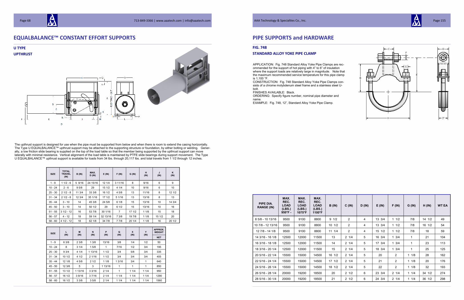
U TYPE
UPTHRUST
EQUALBALANCE™ CONSTANT EFFORT SUPPORTS
The upthrust support is designed for use when the pipe must be supported from below and when there is room to extend the casing horizontally. The Type U EQUALBALANCE™ upthrust support may be attached to the supporting structure or foundation, by either bolting or welding. Gener-ally, a low friction slide bearing is supplied on the top of the load table so that the member being supported by the upthrust support can move laterally with minimal resistance. Vertical alignment of the load table is maintained by PTFE slide bearings during support movement. The Type U EQUALBALANCE™ upthrust support is available for loads from 34 lbs. through 20,117 lbs. and total travels from 1 1/2 through 12 inches.
SIZE
TOTAL TRAVEL
(IN) B (IN)
MAX.
D (IN) E (IN) F (IN) G (IN)
H
(IN)
J
(IN)
K
(IN)
1 - 9 1 1/2 - 6 5 9/16 24 15/16 12 1/4 3 11/16 8 9/16 6 9
10 - 24 2 - 6 9 5/8 29 15 1/2 4 1/4 10 9/16 6 10
25 - 30 2 1/2 - 8 11 3/4 33 3/8 16 1/2 4 5/8 13 11/16 8 12 1/2
31 - 34 2 1/2 - 8 12 3/4 35 1/16 17 1/2 5 1/16 13 13/16 8 13
35 - 44 3 - 10 14 45 3/8 24 5/8 6 1/8 15 13/16 10 14 3/4
45 - 50 3 - 10 14 50 1/2 29 6 1/2 15 13/16 10 16
51 - 55 3 1/2 - 12 16 53 7/8 30 1/16 7 17 1/2 1 1/8 15 18
56 - 57 4 - 12 18 59 1/4 32 13/16 7 3/8 19 7/8 1 1/8 15 1/2 20
58 - 60 4 1/2 - 12 18 62 1/8 34 7/8 7 7/8 20 1/4 1 1/8 16 20 1/2
SIZE L
(IN)
M
(IN)
N
(IN)
P
(IN)
Q
(IN)
X
(IN)
Y
(IN)
APPROX. WEIGHT
NET
1 - 9 6 3/8 2 3/8 1 3/8 13/16 3/8 1/4 1/2 50
10 - 24 8 3 1/4 1 5/8 1 7/16 1/2 3/4 195
25 - 30 9 3/4 4 1/4 1 13/16 1 1/2 3/4 5/8 3/4 335
31 - 34 10 1/2 4 1/2 2 1/16 1 1/2 3/4 3/4 3/4 405
35 - 44 12 1/8 4 5/8 2 1/2 1 1/8 1 3/16 3/4 1 640
45 - 50 12 3/8 5 3 1 13/16 1 1 1 850
51 - 55 13 1/2 1 13/16 3 3/16 2 1/4 1 1 1/4 1 1/4 950
56 - 57 16 1/2 3 9/16 3 7/16 2 1/4 1 1/4 1 1/4 1 1/4 1290
58 - 60 16 1/2 3 3/8 3 5/8 2 1/4 1 1/4 1 1/4 1 1/4 1560
713-849-3366 | www.aaatech.com | [email protected] Page 68
PIPE SUPPORTS and HARDWARE
FIG. 748
STANDARD ALLOY YOKE PIPE CLAMP
PIPE DIA.
RANGE (IN)
MAX. REC. LOAD (LBS.) 950°F -
MAX. REC. LOAD (LBS.)
1075°F
MAX. REC. LOAD (LBS.)
1100°F
B (IN) C (IN) D (IN) E (IN) F (IN) G (IN) H (IN) WT EA
8 5/8 - 10 13/16 9500 9100 8800 9 1/2 2 4 13 3/4 1 1/2 7/8 14 1/2 49
10 7/8 - 12 13/16 9500 9100 8800 10 1/2 2 4 13 3/4 1 1/2 7/8 16 1/2 54
12 7/8 - 14 1/8 9500 9100 8800 11 1/4 2 4 15 1/2 1 1/2 7/8 18 59
14 3/16 - 16 1/8 12500 12000 11500 13 2 1/4 5 16 3/4 1 3/4 1 21 104
16 3/16 - 18 1/8 12500 12000 11500 14 2 1/4 5 17 3/4 1 3/4 1 23 113
18 3/16 - 20 1/4 12500 12000 11500 15 2 1/4 5 18 3/4 1 3/4 1 25 125
20 5/16 - 22 1/4 15500 15000 14500 16 1/2 2 1/4 5 20 2 1 1/8 28 162
22 5/16 - 24 1/4 15500 15000 14500 17 1/2 2 1/4 5 21 2 1 1/8 20 176
24 5/16 - 26 1/4 15500 15000 14500 18 1/2 2 1/4 5 22 2 1 1/8 32 193
26 5/16 - 28 1/4 20000 19200 18500 20 2 1/2 6 23 3/4 2 1/4 1 1/4 34 1/2 274
28 5/16 - 30 1/4 20000 19200 18500 21 2 1/2 6 24 3/4 2 1/4 1 1/4 36 1/2 298
APPLICATION: Fig. 748 Standard Alloy Yoke Pipe Clamps are rec-ommended for the support of hot piping with 4” to 6” of insulation where the support loads are relatively large in magnitude. Note that the maximum recommended service temperature for this pipe clamp is 1,100 °F. CONSTRUCTION: Fig. 748 Standard Alloy Yoke Pipe Clamps con-sists of a chrome molybdenum steel frame and a stainless steel U-bolt. FINISHES AVAILABLE: Black. ORDERING: Specify figure number, nominal pipe diameter and name. EXAMPLE: Fig. 748, 12”, Standard Alloy Yoke Pipe Clamp.
AAA Technology & Specialties Co., Inc. Page 155

PIPE SUPPORTS and HARDWARE
FIG. 739
INTERMEDIATE 3-BOLT ALLOY PIPE
CLAMP
NOM. PIPE DIA.
(IN)
MAX. REC. LOAD (LBS.)
950°F
MAX. REC. LOAD (LBS.)
1000°F
MAX. REC. LOAD (LBS.)
1050°F
"A" CTRLINE TO BOLT
(IN)
"B" CTRLINE TO END
(IN)
"C" GAP
(IN)
"D" CTRLINE TO TOP
BOLT (IN)
"E" CTRLINE TO TOP
(IN)
F (IN) "G" Th
(IN)
"G" W
(IN) WT EA
2 2400 1800 1400 2 5/8 3 5/8 1 6 5/8 7 5/8 3/4 3/8 2 7.49
2 1/2 3600 2700 2100 3 4 1/8 1 1/8 7 8 1/8 7/8 3/8 2 1/2 10.36
3 3600 2700 2100 3 3/8 4 1/2 1 1/8 7 3/8 7 1/2 7/8 3/8 3 11.81
3 1/2 3600 2700 2100 3 5/8 4 3/4 1 1/8 7 5/8 8 3/4 7/8 3/8 3 13.01
4 4700 3500 2700 4 1/4 5 1/2 1 1/4 8 1/4 9 1/2 1 1/2 3 19.20
5 4700 3500 2700 4 3/4 6 1 1/4 8 3/4 10 1 1/2 3 20.58
6 4700 3500 2700 5 3/8 6 5/8 1 1/4 10 3/8 11 5/8 1 1/2 3 23.02
8 7600 5650 4400 7 8 5/8 1 1/2 12 13 5/8 1 1/4 3/4 4 55.46
10 7600 5650 4400 8 9 5/8 1 1/2 13 12 1 1/4 3/4 4 56.53
12 7600 5650 4400 9 10 5/8 1 1/2 14 15 5/8 1 1/4 3/4 4 66.29
14 7600 5650 4400 9 3/4 11 3/8 1 1/2 14 3/4 16 3/8 1 1/4 3/4 4 70.11
16 7600 5650 4400 10 3/4 12 1/4 1 1/2 15 3/4 17 3/8 1 1/4 3/4 4 75.21
18 7600 5650 4400 11 3/4 13 1/4 1 1/2 16 3/4 18 3/8 1 1/4 3/4 4 80.51
20 9500 7050 5450 13 14 3/4 1 3/4 18 19 7/8 1 1/2 3/4 6 134.79
24 11000 8150 6300 15 1/2 17 1/4 1 3/4 20 1/2 22 1/4 1 1/2 1 6 201.60
26 11000 8150 6300 16 1/2 18 1/4 1 3/4 21 1/2 23 3/4 1 1/2 1 6 213.92
28 11000 8150 6300 17 1/2 19 3/4 1 3/4 22 1/2 24 3/4 1 1/2 1 6 226.23
30 14500 10750 8300 18 3/4 21 2 1/8 23 3/4 26 1 3/4 1 8 315.67
32 14500 10750 8300 19 3/4 22 2 1/8 24 3/4 27 1 3/4 1 8 329.82
34 14500 10750 8300 20 3/4 23 2 1/8 25 3/4 28 1 3/4 1 8 343.97
36 14500 10750 8300 21 3/4 24 2 1/8 26 3/4 29 1 3/4 1 8 358.69
42 14500 10750 8300 24 3/4 27 2 1/8 29 3/4 32 1 3/4 1 8 401.14
APPLICATION: Fig. 739 Intermediate 3-Bolt Alloy Pipe Clamps are recommended for the support of hot piping with insulation when the temperature exceeds 750°F and is less than 1050°F. Fig. 739 Inter-mediate 3-Bolt Alloy Pipe Clamps have been designed to carry loads larger in magnitude than the Fig. 736 Standard 3-Bolt Alloy Pipe Clamp. The 3 bolt design enables the attachment to the pipe clamp outside of the insulation. For high temperature piping with thick insu-lation and a loading larger than this clamp will carry, a Fig. 742 or 745 3-Bolt Alloy Pipe Clamp may be used. If the temperature and loads dictate, Alloy Yoke Clamps, Fig. 748 or 751, may be used. The se-lection of the proper 3-Bolt Pipe Clamp depends upon the tempera-ture of the piping system and load to be carried. The loads shown on the data chart are listed for 950°F, 1000°F and 1050°F service. CONSTRUCTION: Fig. 739 Intermediate 3-Bolt Alloy Pipe Clamps are made from ASTM A387-Gr. 22 steel plate or bar stock and are provided with three alloy bolts and nuts. FINISHES AVAILABLE: Black. ORDERING: Specify figure number, nominal pipe diameter, name. EXAMPLE: Fig. 739, 12”, Intermediate 3-Bolt Alloy Pipe Clamp.
713-849-3366 | www.aaatech.com | [email protected] Page 154
EQUALBALANCE™ CONSTANT EFFORT SUPPORTS
DIMENSION "A" *
SIZE TOTAL TRAVEL (IN)
1 1/2 2 2 1/2 3 3 1/2 4 4 1/2 5 5 1/2 6 6 1/2
1 - 9 10 1/4 11 1/4 12 1/4 13 1/4 14 1/4 15 1/4 16 1/4 17 1/4 18 1/4 19 1/4
10 - 24 15 3/8 16 3/8 17 3/8 18 3/8 19 3/8 20 3/8 21 3/8 22 3/8 23 3/8
25 - 30 19 20 21 22 23 24 25 26 27
31 - 34 21 22 23 24 25 26 27 28 29
35 -44 22 1/4 23 1/4 24 1/4 25 1/4 26 1/4 27 1/4 28 1/4 29 1/4
45 - 50 23 3/4 24 3/4 25 3/4 26 3/4 27 3/4 28 3/4 29 3/4 30 3/4
51 - 55 27 28 29 30 31 32 33
56 - 57 28 3/8 29 3/8 30 3/8 31 3/8 32 3/8 33 3/8
58 -60 30 7/16 31 7/16 32 7/16 33 7/16 34 7/16
*Dimension "A" is for down travel (cold to hot). For up travel, Increase dimension by length of total travel
SHORT TRAVEL STANDARD TRAVEL
DIMENSION "A" *
SIZE TOTAL TRAVEL (IN)
7 7 1/2 8 8 1/2 9 9 1/2 10 10 1/2 11 11 1/2 12
1 - 9
10 - 24
25 - 30 28 29 30
31 - 34 30 31 32
35 -44 30 1/4 31 1/4 32 1/4 33 1/4 34 1/4 35 1/4 36 1/4
45 - 50 31 3/4 32 3/4 33 3/4 34 3/4 35 3/4 36 3/4 37 3/4
51 - 55 34 35 36 37 38 39 40 41 42 43 44
56 - 57 34 3/8 35 3/8 36 3/8 37 3/8 38 3/8 39 3/8 40 3/8 41 3/8 42 3/8 43 3/8 44 3/8
58 -60 35 7/16 36 7/16 37 7/16 38 7/16 39 7/16 40 7/16 41 7/16 42 7/8 43 7/16 44 7/16 '45 7/16
*Dimension "A" is for down travel (cold to hot). For up travel, Increase dimension by length of total travel
U TYPE (Continued)
UPTHRUST
DIMENSION "C"
SIZE TOTAL TRAVEL (IN)
1 1/2 2 2 1/2 3 3 1/2 4 4 1/2 5 5 1/2 6 6 1/2
1 - 9 5 5 1/2 6 6 1/2 7 7 1/2 8 8 1/2 9 9 1/2
10 - 24 7 5/8 8 1/8 8 5/8 9 1/8 9 5/8 10 1/8 10 5/8 11 1/8 11 5/8
25 - 30 9 3/8 9 7/8 10 3/8 10 7/8 11 3/8 11 7/8 12 3/8 12 7/8 13 3/8
31 - 34 10 1/2 11 11 1/2 12 12 1/2 13 13 1/2 14 14 1/2
35 -44 11 11 1/2 12 12 1/2 13 13 1/2 14 14 1/2
45 - 50 11 7/8 12 3/8 12 7/8 13 3/8 13 7/8 14 3/8 14 7/8 15 3/8
51 - 55 13 1/2 14 14 1/2 15 15 1/2 16 16 1/2
56 - 57 14 1/2 15 15 1/2 16 16 1/2 17
58 -60 15 9/16 16 1/16 16 9/16 17 1/16 17 9/16
SHORT TRAVEL STANDARD TRAVEL
DIMENSION "C"
SIZE TOTAL TRAVEL (IN)
7 7 1/2 8 8 1/2 9 9 1/2 10 10 1/2 11 11 1/2 12
1 - 9
10 - 24
25 - 30 13 7/8 14 3/8 14 7/8
31 - 34 15 15 1/2 16
35 -44 15 15 1/2 16 16 1/2 17 17 1/2 18
45 - 50 15 7/8 16 3/8 16 7/8 17 3/8 17 7/8 18 3/8 18 7/8
51 - 55 17 17 1/2 18 18 1/2 19 19 1/2 20 20 1/2 21 21 1/2 22
56 - 57 17 1/2 18 18 1/2 19 19 1/2 20 20 1/2 21 21 1/2 22 22 1/2
58 -60 18 1/16 18 9/16 19 1/16 19 9/16 20 1/16 20 9/16 21 1/16 21 9/16 22 1/16 22 9/16 23 1/16
AAA Technology & Specialties Co., Inc. Page 69

LIGHT DUTY SPRING HANGERS
FIG. 75
LIGHT DUTY SINGLE SPRING HANGER
BLACK OR PAINT FINISH
FIG. 76
LIGHT DUTY DOUBLE SPRING HANGER
BLACK OR PAINT FINISH
APPLICATION: Light Duty Single Spring Hangers are recommended for supporting piping systems where the load to be carried is of a small magnitude and thermal movement must be allowed. For applications where movements exceed the allowed movements, two or more spring hangers can be used in series or a light-duty double spring can be used. For applications where loads exceed the allowed loads for the light duty spring hangers, select a Fig. E-82 or Fig. E-268 engineered spring hanger. CONSTRUCTION: Light Duty Single Spring Hangers are constructed of carbon steel. FINISHES AVAILABLE: Black or Painted ORDERING: Specify figure number, Hanger Size, name and finish, if other than black.
HANGER
SIZE
MAX. LOAD RATING
(LBS)
MAX.
MVMNT (IN)
SPRING CONST.
(LBS/IN)
APRX WT.
EACH (LBS)
ROD DIA.
A (IN)
ROD TAKEOUT LENGTH
E (IN)
CASING OUTSIDE
DIA.
D (IN)
CASING LENGTH
C (IN)
SHIPPING LENGTH
B (IN)
1 46 6 7.7 4.38 3/8 9 1/2 3 1/2 9 7/8 10 13/16
2 131 5 26.2 6.35 3/8 10 1/2 3 1/2 10 5/8 11 11/16
3 220 4 55 10.27 1/2 10 5/8 3 1/2 10 7/8 12 1/8
APPLICATION: Light Duty Double Spring Hangers are recommended for supporting piping systems where the load to be carried is of a small magnitude and thermal movement must be allowed. For applications where movements exceed the allowed movements, two or more spring hangers can be used in series. For applications where loads exceed the allowed loads for the light duty spring hangers, select a Fig. E-268 or Fig. E-98 engineered spring hanger. CONSTRUCTION: Light Duty Double Spring Hangers are constructed of carbon steel. FINISHES AVAILABLE: Black or Painted ORDERING: Specify figure number, Hanger Size, name and finish, if other than black.
HANGER
SIZE
MAX. LOAD RATING
(LBS)
MAX.
MVMNT (IN)
SPRING CONST.
(LBS/IN)
APPRX WT.
EACH (LBS)
ROD DIA.
A (IN)
ROD TAKE-OUT LENGTH
E (IN)
CASING OUTSIDE
DIA.
D (IN)
CASING LENGTH
C (IN)
SHIPPING LENGTH
B (IN)
1 46 3 15.4 2.5 3/8 5 1/4 3 1/2 5 7/16 6 9/16
2 131 2 1/2 52.5 3.63 3/8 5 1/4 3 1/2 5 13/16 6 9/16
3 220 2 110 5.87 1/2 5 5/8 3 1/2 6 7 1/8
713-849-3366 | www.aaatech.com | [email protected] Page 70
PIPE SUPPORTS and HARDWARE
FIG. 736
STANDARD 3-BOLT ALLOY PIPE
CLAMP
NOM. PIPE
DIA. (IN)
MAX. REC. LOAD (LBS.)
950°F
MAX. REC. LOAD (LBS.)
1000°F
MAX. REC. LOAD (LBS.)
1050°F
"A" CTRLINE TO BOLT
(IN)
"B" CTRLINE TO END
(IN)
"C" GAP
(IN)
"D" CTRLINE TO TOP
BOLT (IN)
"E" CTRLINE
TO TOP F (IN)
"G" Th
(IN)
"G" W
(IN) WT EA
3/4 1550 1100 810 1 1/4 2 1/2 3 1/16 3 3/4 1/2 1/4 1 1.46
1 1580 1120 830 1 7/16 2 1/8 1/2 3 3/16 3 13/16 1/2 1/4 1 1.51
1 1/4 2000 1410 1050 1 9/16 2 1/2 1 4 1/8 4 7/8 5/8 1/4 1 1/4 2.57
1 1/2 2000 1410 1050 1 5/8 2 5/8 1 4 1/8 4 7/8 5/8 1/4 1 1/4 2.62
2 1930 1360 1010 2 2 7/8 1 5 1/8 5 7/8 5/8 1/4 1 1/4 2.88
2 1/2 1860 1300 970 2 5/16 3 1/8 1 5 3/8 6 1/8 5/8 1/4 1 1/4 3.02
3 1720 1210 900 2 5/8 3 1/4 1 5 7/8 6 11/16 5/8 1/4 1 1/4 3.21
3 1/2 1620 1190 880 3 1/8 3 7/8 1 6 1/4 7 1/8 5/8 1/4 1 1/4 3.46
4 3800 2990 2200 3 1/2 4 1/2 1 6 1/2 7 5/8 3/4 3/8 2 8.39
5 3400 2410 1790 4 1/8 5 1/16 1 7 8 1/8 3/4 3/8 2 9.08
6 3750 2650 1980 4 5/8 6 1/8 1 3/8 8 1/2 9 15/16 7/8 3/8 2 1/2 13.51
8 2850 2040 1520 5 3/4 7 1/8 1 3/8 9 1/2 10 15/16 7/8 3/8 2 1/2 15.16
10 3900 2770 2060 7 1/4 8 1/4 1 3/8 10 5/8 12 1 1/2 2 1/2 23.32
12 3750 2650 1970 8 1/8 9 7/8 2 12 3/8 13 7/8 1 1/2 2 1/2 26.61
14 3800 2800 2050 9 1/8 10 5/8 2 12 11/16 14 3/8 1 1/4 5/8 3 44.21
16 3800 2800 2050 10 1/8 11 5/8 2 13 11/16 15 3/8 1 1/4 5/8 3 47.54
18 3750 2750 2050 11 1/8 12 5/8 2 14 11/16 16 3/8 1 1/4 5/8 3 50.86
20 4650 3550 2620 12 3/8 14 2 15 7/8 17 5/8 1 3/8 3/4 3 72.16
24 3950 2900 2150 14 3/8 16 1/8 2 17 7/8 19 1/2 1 3/8 3/4 3 80.12
26 4500 3300 2450 15 3/4 17 1/4 2 20 1/2 22 1 1/4 3/4 4 101.10
28 4500 3300 2450 16 3/4 18 1/4 2 21 1/2 23 1 1/4 3/4 4 106.41
30 4000 3300 2450 18 19 3/4 2 23 24 3/4 1 1/2 3/4 4 122.81
APPLICATION: Fig. 736 Standard 3-Bolt Alloy Pipe Clamps are rec-ommended for the support of hot piping with insulation when the tem-perature exceeds 750°F and is less than 1050°F. Fig. 736 Standard 3-Bolt Alloy Pipe Clamps have been designed to carry loads that are not large in magnitude. The 3 bolt design enables the attachment to the pipe clamp outside of the insulation. For high temperature piping with thick insulation and a loading larger than this clamp will carry, a Fig. 739, 742 or 745 3-Bolt Alloy Pipe Clamp may be used. If the temperature and loads dictate, Alloy Yoke Clamps, Fig. 748 or 751, may be used. The selection of the proper 3-Bolt Pipe Clamp depends upon the temperature of the piping system and load to be carried. The loads shown on the data chart are listed for 950°F, 1000°F and 1050°F service. CONSTRUCTION: Fig. 736 Standard 3-Bolt Alloy Pipe Clamps are made from ASTM A387-Gr. 22 steel plate or bar stock and are provid-ed with three alloy bolts and nuts. FINISHES AVAILABLE: Black. ORDERING: Specify figure number, nominal pipe diameter, name. EXAMPLE: Fig. 736, 8”, Standard 3-Bolt Alloy Pipe Clamp.
AAA Technology & Specialties Co., Inc. Page 153

PIPE SUPPORTS and HARDWARE
FIG. 733
EXTRA HEAVY 3-BOLT PIPE CLAMP
APPLICATION: Fig. 733 Extra Heavy 3-Bolt Pipe Clamps are recom-mended for the support of hot piping with insulation. Fig. 733 Extra Heavy 3-Bolt Pipe Clamps have been designed to carry loads that are larger in magnitude than can be carried by the Fig. 730 Heavy 3-Bolt Pipe Clamp. The 3 bolt design enables the attachment to the pipe clamp outside of the insulation. For high temperature piping with thick insulation and a loading larger than this clamp will carry, contact AAA Technology for a custom fabricated clamp to fit your require-ments. If the temperature dictates, a Fig. 736, 739, 742 or 745 Alloy 3-Bolt Pipe Clamp may be an option for your application. The selec-tion of the proper 3-Bolt Pipe Clamp depends upon the temperature of the piping system and load to be carried. Alloy pipe clamps and stainless steel pipe clamps are also available. The loads shown on the data chart are listed for 750°F and 650°F service. CONSTRUCTION: Fig. 733 Extra Heavy 3-Bolt Pipe Clamps are made from carbon steel plate or bar stock and are provided with three bolts and nuts. FINISHES AVAILABLE: Black, Hot Dip Galvanized, Electro-Plated or Painted. ORDERING: Specify figure number, nominal pipe diameter, name and finish, if other than black. EXAMPLE: Fig. 733, 10”, Extra Heavy 3-Bolt Pipe Clamp, HDG.
NOM. PIPE
DIA. (IN)
MAX LOAD
650°F
MAX LOAD
750°F
"A" CTRLINE TO BOLT
(IN)
"B" CTRLINE TO END
(IN)
"C" GAP (IN)
"D" CTRLINE TO TOP BOLT
(IN)
"E" CTRLINE TO
TOP END
(IN)
F (IN) "G" Th
(IN)
"G" W
(IN) WT EA
1 1900 1690 1 5/8 2 3/8 1 4 5/8 5 3/8 5/8 5/16 2 4.13
1 1/4 1900 1690 1 3/4 2 1/2 1 4 3/4 5 1/2 5/8 5/16 2 4.30
1 1/2 2300 2050 2 2 3/4 1 1/8 4 3/4 5 1/2 3/4 3/8 2 6.17
2 2300 2050 2 5/16 3 1 1/8 5 7/16 6 3/16 3/4 3/8 2 6.70
2 1/2 2300 2050 2 1/2 3 3/8 1 1/8 5 11/16 6 7/16 3/4 3/8 2 7.07
3 2300 2050 3 1/16 3 7/8 1 1/8 6 3/16 6 15/16 3/4 3/8 2 7.65
3 1/2 2300 2050 3 3/8 4 1/4 1 1/8 6 9/16 7 3/8 3/4 3/8 2 8.13
4 3600 2700 3 3/4 4 3/4 1 3/4 7 1/8 7 7/8 7/8 3/8 2 9.41
5 3600 2700 4 3/16 5 3/16 1 3/4 7 5/8 8 3/8 7/8 3/8 2 10.05
6 4500 4000 5 3/16 6 1/4 1 3/4 8 15/16 10 1/4 1 1/2 2 1/2 18.79
8 6000 5300 6 3/8 7 3/8 2 10 1/8 11 3/8 1 1/8 5/8 2 1/2 27.62
10 6750 6000 7 3/8 9 2 1/4 11 3/8 13 1/8 1 1/4 5/8 3 1/2 43.81
12 7000 6250 8 5/8 10 1/4 2 1/2 12 9/16 14 5/16 1 3/8 5/8 3 1/2 55.96
14 9500 8450 9 5/8 11 5/8 2 1/2 13 1/2 15 1/2 1 1/2 3/4 4 77.85
16 10000 8920 10 7/8 13 1/8 3 14 7/8 17 1/8 1 3/4 3/4 4 1/2 98.23
18 13800 12300 12 1/2 14 1/2 3 1/2 16 1/4 18 1/4 2 1 4 134.50
20 15300 13650 13 1/2 16 3 1/2 17 1/4 19 3/4 2 1 5 169.91
24 16300 14500 15 1/2 18 1/2 3 1/2 19 1/4 22 5/16 2 1 6 220.74
26 17500 15600 16 7/8 20 7/8 3 1/2 25 1/4 29 5/8 2 1/4 1 7 307.04
28 18000 16000 18 7/8 23 3/8 4 27 1/4 31 5/8 2 1/4 1 7 331.00
30 20500 18250 19 7/8 24 3/8 4 1/4 28 1/4 32 3/4 2 1/4 1 8 383.86
32 23750 21150 21 3/4 26 3/4 4 1/4 31 35 3/4 2 1/2 1 1/4 8 522.98
34 25000 22250 23 3/8 28 3/8 4 1/4 32 1/2 37 1/2 2 1/2 1 1/2 7 575.12
36 28000 25000 24 5/8 30 4 1/2 34 3/4 40 1/8 2 3/4 1 1/2 8 724.55
42 32300 28750 29 35 1/2 4 1/2 35 3/8 40 3/4 2 3/4 1 1/2 9 873.05
713-849-3366 | www.aaatech.com | [email protected] Page 152
LIGHT DUTY SPRING HANGERS
FIG. 77
LIGHT DUTY SINGLE SPRING HANGER
HDG FINISH
FIG. 78
LIGHT DUTY DOUBLE SPRING HANGER
HDG FINISH
APPLICATION: Light Duty Single Spring Hangers are recommended for supporting piping systems where the load to be carried is of a small magnitude and thermal movement must be allowed. The corrosion resistant model is hot dip galvanized and then mechanically closed. No welding is performed on the components after galvanizing. For applications where movements exceed the allowed movements, two or more spring hangers can be used in series or a light duty double spring can be used. For applications where loads exceed the allowed loads for the light duty spring hangers, select a Fig. E-82 or Fig. E-268 engi-neered spring hanger. CONSTRUCTION: Light Duty Single Spring Hangers are constructed of carbon steel. FINISHES AVAILABLE: HDG ORDERING: Specify figure number, Hanger Size, name and finish, if other than black. EXAMPLE: Fig. 77, Size 2, Light Duty Single Spring Hanger, HDG
HANGER
SIZE
MAX. LOAD RATING
(LBS)
MAX.
MVMNT (IN)
SPRING CONST.
(LBS/IN)
APRX WT.
EACH (LBS)
ROD DIA.
A (IN)
ROD TAKEOUT LENGTH
E (IN)
CASING OUTSIDE
DIA.
D (IN)
CASING LENGTH
C (IN)
SHIPPING LENGTH
B (IN)
1 46 3 15.4 2.75 3/8 5 1/4 3 1/2 5 7/16 6 9/16
2 131 2 1/2 52.5 3.93 3/8 5 1/4 3 1/2 5 13/16 6 9/16
3 220 2 110 6.27 1/2 5 5/8 3 1/2 6 7 1/8
HANGER
SIZE
MAX. LOAD RATING
(LBS)
MAX.
MVMNT (IN)
SPRING CONST.
(LBS/IN)
APRX WT.
EACH (LBS)
ROD DIA.
A (IN)
ROD TAKEOUT LENGTH
E (IN)
CASING OUTSIDE
DIA.
D (IN)
CASING LENGTH
C (IN)
SHIPPING LENGTH
B (IN)
1 46 6 7.7 4.63 3/8 9 1/2 3 1/2 9 7/8 10 13/16
2 131 5 26.2 6.65 3/8 10 1/2 3 1/2 10 5/8 11 11/16
3 220 4 55 10.67 1/2 10 5/8 3 1/2 10 7/8 12 1/8
APPLICATION: Light Duty Double Spring Hangers are recommended for supporting piping systems where the load to be carried is of a small magnitude and thermal movement must be allowed. The corrosion resistant model is hot dip galvanized and then mechanically closed. No welding is performed on the components after galvanizing. For applications where movements exceed the allowed movements, two or more spring hangers can be used in series. For applications where loads exceed the allowed loads for the light duty spring hangers, select a Fig. E-268 or Fig. E-98 engineered spring hanger. CONSTRUCTION: Light Duty Double Spring Hangers are constructed of carbon steel. FINISHES AVAILABLE: HDG ORDERING: Specify figure number, Hanger Size, name and finish, if other than black. EXAMPLE: Fig. 78, Size 1, Light Duty Double Spring Hanger, HDG
AAA Technology & Specialties Co., Inc. Page 71

STRUTS
FIG. 300 WELDED SWAY STRUT ASSEMBLY
DIMENSIONAL DATA
SWAY STRUT
SIZE
MAX. RATED
TENSION LOAD
(LBS)
ROD END EXTENSION PIECE REAR BRACKET
NOM. PIN/STUD DIA.
T (IN)
WELD
SIZE X (IN)
C - C LENGTH
MIN. (IN)
MAX. ADJUST-
MENT (IN) DIA. (IN)
PADDLE RADIUS MAX. R
(IN)
FL (IN) FR (IN) PIPE DIA. (IN) LENGTH
MIN. L (IN)
TAKE OUT A
(IN)
H
(IN)
W
(IN)
GAP
(G)
0 738 1/2 3/4 1 7/8 3 7/8 1/2 XS 10 1/4 1 1/4 1 1/4 1 1/4 9/16 3/8 1/8 16 2
1/2 1434 3/4 1 2 1/4 4 1/4 1 S160 10 1/2 1 3/4 1 1/2 1 1/4 21/32 1/2 1/4 17 2
1 5950 1 1 3/8 2 5/8 4 5/8 1 1/4 S160 11 2 1/4 2 1 1/2 25/32 5/8 1/4 18 1/4 2
2 9750 1 1/4 1 1/2 2 13/16 4 13/16 1 1/2 S160 11 3/4 2 1/2 2 1/4 2 29/32 3/4 9/32 19 3/8 2
3 11900 1 1/2 1 1/2 2 15/16 5 7/16 2 XXS 13 2 3/4 2 5/8 2 1/4 1 1/32 1 7/16 21 3/8 2 1/2
4 19350 1 3/4 2 1/4 5 15/16 8 7/16 2 1/2 XXS 13 3/4 3 1/2 3 3/4 3 1 19/32 1 1/4 9/16 28 1/8 2 1/2
5 22800 2 2 1/4 5 3/4 8 3/4 2 1/2 S160 14 3/4 3 1/2 3 3/4 3 1 19/32 1 1/4 3/8 29 1/4 3
6 27600 2 1/4 2 1/2 6 3/4 9 3/4 3 XXS 15 3/4 4 1/2 5 3 3/4 1 25/32 1 1/2 5/8 32 1/4 3
7 40850 2 1/2 3 8 1/16 11 9/16 3 S160 16 1/2 5 7 7 2 7/32 1 3/4 7/16 36 1/8 3 1/2
8 46200 3 3 8 5/16 11 15/16 4 XXS 18 5 7 7 2 7/32 1 3/4 21/32 38 1/8 3 1/2
9 64400 3 1/2 3 1/4 8 9/16 12 1/16 4 S120 19 3/4 5 3/4 8 8 2 13/32 2 7/16 40 3/8 3 1/2
10 95950 4 3/4 4 3/4 10 1/2 14 5 XS 23 3/4 7 1/2 10 10 3 7/16 2 3/4 3/8 48 1/4 3 1/2
11 138700 5 3/4 6 5/16 14 1/16 17 7/16 6 XS 26 3/4 9 1/2 13 13 4 5/16 3 3/4 7/16 58 1/4 3 1/2
*Please refer to F. 310 for Dimension K.
713-849-3366 | www.aaatech.com | [email protected] Page 72
PIPE SUPPORTS and HARDWARE
FIG. 730
HEAVY 3-BOLT PIPE CLAMP
APPLICATION: Fig. 730 Heavy 3-Bolt Pipe Clamps are recommend-ed for the support of hot piping with insulation. Fig. 730 Heavy 3-Bolt Pipe Clamps have been designed to carry loads that are larger in magnitude than can be carried by the Fig. 727 Intermediate 3-Bolt Pipe Clamp. The 3 bolt design enables the attachment to the pipe clamp outside of the insulation. For high temperature piping with thick insulation and a loading larger than this clamp will carry, a Fig. 733 3-Bolt Pipe Clamp may be used. If the temperature dictates, a Fig. 736, 739, 742 or 745 Alloy 3-Bolt Pipe Clamp may be used. The selection of the proper 3 Bolt Pipe Clamp depends upon the tempera-ture of the piping system and load to be carried. Alloy pipe clamps and stainless steel pipe clamps are also available. The loads shown on the data chart are listed for 750°F and 650°F service. CONSTRUCTION: Fig. 730 Heavy 3-Bolt Pipe Clamps are made from carbon steel plate or bar stock and are provided with three bolts and nuts. FINISHES AVAILABLE: Black, Hot Dip Galvanized, Electro-Plated or Painted. ORDERING: Specify figure number, nominal pipe diameter, name and finish, if other than black. EXAMPLE: Fig. 730, 12”, Heavy 3-Bolt Pipe Clamp, HDG.
NOM. PIPE
DIA. (IN)
MAX LOAD
650°F
MAX LOAD
750°F
"A" CTRLINE TO BOLT
(IN)
"B" CTRLINE TO END
(IN)
"C" GAP (IN)
"D" CTRLINE TO TOP BOLT
(IN)
"E" CTRLINE TO
TOP END
(IN)
F (IN) "G" Th
(IN)
"G" W
(IN) WT EA
1/2 1200 1080 1 5/16 1 13/16 1 2 9/16 3 1/16 1/2 1/4 1 1/2 1.71
3/4 1200 1080 1 7/16 1 15/16 1 2 9/16 3 1/16 1/2 1/4 1 1/2 1.76
1 1200 1080 1 9/16 2 1/16 1 2 11/16 3 1/4 1/2 1/4 1 1/2 1.86
1 1/4 1200 1080 1 3/4 2 5/16 1 2 3/4 3 3/8 1/2 1/4 1 1/2 1.97
1 1/2 1900 1720 2 2 7/16 1 1/8 4 9/16 5 1/8 11/16 5/16 2 6.76
2 1900 1720 2 5/16 2 15/16 1 1/8 5 7/16 6 1/4 11/16 5/16 2 7.43
2 1/2 1900 1720 2 1/2 3 3/16 1 1/8 5 11/16 6 3/8 11/16 5/16 2 7.65
3 1900 1720 3 1/16 3 3/4 1 1/8 6 3/16 6 15/16 11/16 5/16 2 8.18
3 1/2 1900 1720 3 3/8 4 3/16 1 1/8 6 9/16 7 3/8 11/16 5/16 2 8.58
4 3000 2700 3 3/4 4 5/8 1 3/4 7 1/8 7 7/8 3/4 3/8 2 8.62
5 3000 2700 4 3/16 5 3/16 2 7 5/8 8 3/8 3/4 3/8 2 9.24
6 3500 3150 5 3/16 6 3/8 2 8 3/4 9 7/8 1 3/8 2 1/2 14.94
8 4800 4300 6 3/8 7 1/2 2 9 7/8 11 1 1/8 1/2 2 1/2 22.76
10 5400 4900 7 3/8 8 5/8 2 11 1/8 12 3/8 1 1/4 1/2 3 1/2 35.28
12 5400 4900 8 3/8 9 5/8 2 12 1/8 13 3/8 1 1/4 1/2 3 1/2 38.38
14 5400 4900 9 1/2 11 2 1/4 13 1/8 14 5/8 1 3/8 3/4 3 59.96
16 5400 4900 10 1/2 12 2 1/4 14 1/8 15 5/8 1 3/8 3/4 3 63.94
18 6500 5900 11 1/2 13 2 1/4 15 1/8 16 5/8 1 1/2 3/4 3 1/2 77.99
20 6500 5900 12 3/8 14 3/8 2 1/4 16 1/2 18 1 1/2 3/4 3 1/2 83.76
24 6500 5900 15 16 5/8 2 1/4 18 5/8 20 1/4 1 1/2 7/8 4 119.27
26 6500 5900 16 1/4 18 1/2 2 1/2 20 1/2 22 7/8 1 1/2 7/8 4 130.01
28 6500 5900 18 20 1/2 2 1/2 22 1/4 24 7/8 1 1/2 7/8 4 140.17
30 9600 8750 19 21 3/4 2 3/4 24 26 7/8 1 3/4 1 5 210.00
32 10500 9500 21 1/8 23 1/8 2 3/4 25 1/2 28 5/8 1 3/4 1 6 261.13
34 11600 10500 22 25 1/2 3 1/4 28 1/4 31 7/8 1 3/4 1 6 283.53
36 12400 11300 23 26 1/2 3 1/4 29 1/4 32 7/8 1 3/4 1 6 294.57
42 12400 11300 29 32 3/4 3 1/4 35 3/8 39 3/8 1 3/4 1 6 349.34
AAA Technology & Specialties Co., Inc. Page 151

PIPE SUPPORTS and HARDWARE
FIG. 727
INTERMEDIATE 3-BOLT PIPE CLAMP
APPLICATION: Fig. 727 Intermediate 3-Bolt Pipe Clamps are recom-mended for the support of hot piping with insulation. Fig. 727 Inter-mediate 3-Bolt Pipe Clamps have been designed to carry loads that are larger in magnitude than can be carried by the Fig. 724 Standard 3-Bolt Pipe Clamp. The 3 bolt design enables the attachment to the pipe clamp outside of the insulation. For high temperature piping with thick insulation and a loading larger than this clamp will carry, a Fig. 730 or 733 3-Bolt Pipe Clamp may be used. If the temperature dic-tates, a Fig. 736, 739, 742 or 745 Alloy 3-Bolt Pipe Clamp may be used. The selection of the proper 3-Bolt Pipe Clamp depends upon the temperature of the piping system and load to be carried. Alloy pipe clamps and stainless steel pipe clamps are also available. The loads shown on the data chart are listed for 750°F and 650°F service. CONSTRUCTION: Fig. 727 Standard 3-Bolt Pipe Clamps are made from carbon steel plate or bar stock and are provided with three bolts and nuts. FINISHES AVAILABLE: Black, Hot Dip Galvanized, Electro-Plated or Painted. ORDERING: Specify figure number, nominal pipe diameter, name and finish, if other than black. EXAMPLE: Fig. 727, 8”, Intermediate 3-Bolt Pipe Clamp, HDG.
NOM. PIPE
DIA. (IN)
MAX LOAD
650°F
MAX LOAD
750°F
"A" CTRLINE TO BOLT
(IN)
"B" CTRLINE TO END
(IN)
"C" GAP (IN)
"D" CTRLINE TO TOP BOLT
(IN)
"E" CTRLINE TO
TOP END
(IN)
F (IN) "G" Th
(IN)
"G" W
(IN) WT EA
1/2 950 850 1 1/8 1 5/8 5/8 2 3/8 2 7/8 3/8 3/16 1 0.77
3/4 950 850 1 1/4 1 3/4 5/8 2 3/8 2 7/8 3/8 3/16 1 0.80
1 950 850 1 3/8 1 7/8 5/8 2 1/2 3 3/8 3/16 1 0.84
1 1/4 950 850 1 9/16 2 1/8 5/8 2 9/16 3 1/8 3/8 3/16 1 0.91
1 1/2 1540 1380 1 13/16 2 1/4 1 1/16 4 3/8 4 7/8 5/8 1/4 1 1/4 2.54
2 1540 1380 2 1/8 2 3/4 1 1/16 5 1/4 5 7/8 5/8 1/4 1 1/4 2.87
2 1/2 1540 1380 2 5/16 2 15/16 1 1/16 5 1/2 6 1/8 5/8 1/4 1 1/4 2.98
3 1540 1380 2 7/8 3 1/2 1 1/16 6 6 11/16 5/8 1/4 1 1/4 3.24
3 1/2 1540 1380 3 3/16 3 15/16 1 1/16 6 3/8 7 1/8 3/4 1/4 1 1/4 4.42
4 2500 2230 3 1/2 4 3/8 1 1/16 6 7/8 7 5/8 3/4 5/16 2 7.24
5 2500 2230 3 15/16 4 15/16 1 1/16 7 3/8 8 1/8 3/4 5/16 2 7.86
6 2860 2550 5 6 1/8 1 7/16 8 1/2 9 5/8 7/8 3/8 2 11.33
8 2860 2550 6 7 1/8 1 7/16 9 1/2 10 5/8 7/8 3/8 2 12.66
10 3240 2880 7 8 1/4 1 7/16 10 3/4 12 1 1/2 2 1/2 23.25
12 3240 2880 8 9 1/4 1 7/16 11 3/4 13 1 1/2 2 1/2 25.46
14 4300 3830 9 1/8 10 5/8 2 12 3/4 14 1/4 1 1/4 5/8 3 44.08
16 4300 3830 10 1/8 11 5/8 2 13 3/4 15 1/4 1 1/4 5/8 3 47.40
18 4300 3830 11 1/8 12 5/8 2 14 3/4 16 1/4 1 1/4 5/8 3 50.72
20 5480 4900 12 3/8 14 2 16 1/8 17 5/8 1 3/8 3/4 3 72.16
24 4500 4010 14 1/2 16 1/8 2 18 1/8 19 5/8 1 3/8 3/4 3 80.28
26 4250 3800 15 3/4 18 2 1/4 20 22 1/4 1 3/8 3/4 3 87.34
28 5800 5100 17 1/2 20 2 1/4 21 3/4 24 1/4 1 3/8 3/4 4 119.20
30 7400 6600 18 1/2 21 1/4 2 1/2 23 1/2 26 1/4 1 3/8 3/4 5 154.96
32 8200 7300 19 5/8 22 5/8 2 1/2 25 28 1 1/2 3/4 6 192.86
34 9800 8700 21 1/2 25 3 27 3/4 31 1/4 1 3/4 1 5 238.37
36 10400 9300 22 1/2 26 3 28 3/4 32 1/4 1 3/4 1 5 247.58
713-849-3366 | www.aaatech.com | [email protected] Page 150
STRUTS
MAXIMUM RATED COMPRESSION LOAD (KIPS)*
SWAY STRUT
SIZE
C-C
@MIN
LENGTH 2'-0" 2"-6" 3'-0" 3'-6" 4'-0" 4'-6" 5'-0" 5'-6" 6'-0" 7'-0" 8'-0" 9'-0" 10'-0" 11'-0" 12'-0" 13'-0" 14'-0"
0 0.738 0.738 0.738 0.738 0.604
1/2 1.434 1.434 1.434 1.434 1.434 1.434 1.434 1.434 1.361
1 5.95 5.95 5.95 5.95 5.95 5.95 5.57 5.19 4.424 3.658 2.708
2 9.75 9.75 9.75 9.75 9.75 9.75 9.75 9.75 8.77 7.791 5.783 4.45 3.71
3 11.9 11.9 11.9 11.9 11.9 11.9 11.9 11.9 11.9 11.9 10.69 8.21 6.5 5.25 4.32
4 19.35 19.35 19.35 19.35 19.35 19.35 19.35 19.35 19.35 19.35 15.56 12.41 10.06 8.26 6.91 5.86
5 22.8 22.8 22.8 22.8 22.8 22.8 22.8 22.8 22.8 22.8 22.8 18.24 14.59 11.84 9.745 8.145 6.845
MAXIMUM RATED COMPRESSION LOAD (KIPS)*
SWAY STRUT
SIZE
C-C
@MIN
LENGTH 9'-0" 10'-0" 11'-0" 12'-0" 13'-0" 14'-0" 15'-0" 16'-0" 17'-0" 18'-0" 19'-0" 20'-0" 21-0" 22'-0" 23'-0" 24'-0" 25'-0"
6 27.6 27.6 26.77 22.27 18.72 15.92 13.67 11.87 11.87
7 40.85 36.49 30.49 25.59 20.99 17.59 14.89 12.69 10.89 9.391
8 46.2 46.2 46.2 46.2 46.2 46.2 43.45 37.85 34.6 30.05 26.25 23.05 20.3 17.95
9 64.4 64.4 61.52 54.92 48.32 42.12 36.52 31.42 34.6 23.62 20.62 18.12 16.02 14.02 12.62
10 95.95 85.28 80.98 76.28 70.88 65.28 59.38 53.68 34.6 43.08 38.38 33.88 30.28 26.88 23.88 21.58 19.28 17.38
11 138.7 124.4 120 115.2 109.8 104 98.03 91.43 34.6 77.83 71.23 64.83 59.03 53.43 48.43 43.63 39.23 35.23
APPLICATION: Welded Sway Strut Assemblies are used in power plant and process plants of all types to restrain movement of piping in one direction while allowing for movement lateral to the axis of the sway strut. A Welded Sway Strut allows for adjustment of the length in the field at the time of installation. See the installation instructions below for assistance in determining the required sway strut fit-up length. APPLICABLE CODES AND STANDARDS: Welded Sway Struts are manufactured in accordance with the requirements of the U.S. Government and the power and process industries. These include the Federal Specification WW-H-171E, Manufacturers Standardization Society MSS-SP-58, ASME B31.1, B31.3 and B31.5 piping codes. FEATURES: • Handles both compressive and tensile loads • Requires minimal maintenance • Provides up to 3 1/2” field adjustment (plus or minus) at time of installation • Provides for + or – 5° combined angular rotation and misalignment • Field adjustment accomplished by extending the rod connected to the paddle on one end of the strut until the unit is rigid and welding the rod to the exten-sion piece SELECTING THE CORRECT SIZE SWAY STRUT 1. Given the tension load, go to the dimensional table on the regular assembly data sheet. Select the sway strut that has a tension load rating equal to or slightly larger than the design tension load. 2. Given the compression load, go to the maximum rated compression loads table on the regular assembly data sheet. Select the sway strut that has a com-pression load rating equal to or slightly larger than the design compression load. 3. Determine the required C – C dimension. If the unit being specified is option 1, subtract the “A” dimension from the total length to determine the C – C length. If the unit being specified is option 2, subtract two times the “A” dimension from the total length to determine the C – C length. If the unit being speci-fied is option 3, subtract the “A” dimension for the rear bracket and the “K” dimension for the clamp from the total length to determine the C – C length. 4. Given the desired C – C dimension, determine whether the short welded assembly or the regular length assembly is required. Note that if a short welded sway strut is selected, the C – C dimension must be equal to or greater than the minimum C – C and less than or equal to the maximum C – C. If a regular welded sway strut is selected, the C – C dimension must be equal to or greater than the minimum C – C and less than or equal to the length of the smallest maximum rated compression load shown in the charts. CONSTRUCTION: A-36 Carbon Steel, Special materials available on request. FINISHES AVAILABLE: Carbon Steel - Black, Painted or Hot Dip Galvanized. Stainless Steel – Plain (Special). ORDERING: Specify figure number (Fig. 300), name (Welded Sway Strut Assembly), sway strut size (0 through 11), “C-C” dimension, design tension load, design compression load, option number (1, 2 or 3), pipe diameter, if applicable, material, if other than carbon steel, and finish. EXAMPLE: Fig. 300 Welded Sway Strut Assembly, Size 3, C-C = 8’-0”, Tension Load = 10,000 lbs., Compression Load = 7,500 lbs., Option #3, 10” Pipe Dia., HDG. INSTALLATION: 1. Weld rear bracket to the structure, 2. Install strut clamp around pipe for option 3 or weld rear bracket to other member for option 2, 3. Insert loose rod end into the extension piece, 4. Attach one rod end to the rear bracket and the other to the strut clamp,
AAA Technology & Specialties Co., Inc. Page 73

STRUTS
FIG. 301 SHORT WELDED SWAY STRUT ASSEMBLY
DIMENSIONAL DATA
SWAY STRUT
SIZE
MAX. RATED
TENSION LOAD
(LBS)
ROD END EXTENSION PIECE REAR BRACKET
NOM. PIN/STUD DIA.
T (IN)
WELD SIZE X
(IN)
C - C
LENGTH (IN)
DIA. (IN)
PADDLE RADIUS MAX. R
(IN)
FL (IN) FR (IN) PIPE DIA.
(IN)
LENGTH MIN.
L (IN) TAKE OUT A
(IN)
H
(IN)
W
(IN)
GAP
(G) MIN MAX MIN MAX
0 738 1/2 3/4 1 7/8 3 3/8 1/2 XS 3 1/2 10 5/8 1 1/4 1 1/4 1 1/4 9/16 3/8 1/8 8 3/4 15 7/8
1/2 1434 3/4 1 2 1/4 3 3/4 1 S160 3 1/2 10 7/8 1 3/4 1 1/2 1 1/4 21/32 1/2 1/4 9 1/2 16 7/8
1 5950 1 1 3/8 2 5/8 4 1/8 1 1/4 S160 3 1/2 11 3/8 2 1/4 2 1 1/2 25/32 5/8 1/4 10 1/4 181/8
2 9750 1 1/4 1 1/2 2 13/16 4 5/16 1 1/2 S160 3 1/2 12 1/8 2 1/2 2 1/4 2 29/32 3/4 9/32 10 5/8 19 1/4
3 11900 1 1/2 1 1/2 2 15/16 4 7/16 2 XXS 3 1/2 13 7/8 2 3/4 2 5/8 2 1/4 1 1/32 1 7/16 10 7/8 21 1/4
4 19350 1 3/4 2 1/4 5 15/16 7 7/16 2 1/2 XXS 3 1/2 14 5/8 3 1/2 3 3/4 3 1 19/32 1 1/4 9/16 16 7/8 28
5 22800 2 2 1/4 5 3/4 7 1/4 2 1/2 S160 3 1/2 16 1/8 3 1/2 3 3/4 3 1 19/32 1 1/4 3/8 16 1/2 29 1/8
6 27600 2 1/4 2 1/2 6 3/4 8 1/4 3 XXS 3 1/2 17 1/8 4 1/2 5 3 3/4 1 25/32 1 1/2 5/8 18 1/2 32 1/8
7 40850 2 1/2 3 8 1/16 9 9/16 3 S160 3 1/2 18 3/8 5 7 7 2 7/32 1 3/4 7/16 21 1/8 36
8 46200 3 3 8 5/16 9 13/16 4 XXS 3 1/2 19 7/8 5 7 7 2 7/32 1 3/4 21/32 21 5/8 38
9 64400 3 1/2 3 1/4 8 9/16 10 1/16 4 S120 3 1/2 21 5/8 5 3/4 8 8 2 13/32 2 7/16 22 1/8 40 1/4
10 95950 4 3/4 4 3/4 10 1/2 12 5 XS 3 1/2 25 3/4 7 1/2 10 10 3 7/16 2 3/4 3/8 26 48 1/4
11 138700 5 3/4 6 5/16 14 1/16 15 9/16 6 XS 3 1/2 28 3/4 9 1/2 13 13 4 5/16 3 3/4 7/16 33 1/8 58 3/8
*Please refer to F. 310 for Dimension K.
713-849-3366 | www.aaatech.com | [email protected] Page 74
PIPE SUPPORTS and HARDWARE
FIG. 724
STANDARD 3-BOLT PIPE CLAMP
APPLICATION: Fig. 724 Standard 3-Bolt Pipe Clamps are recom-mended for the support of hot piping with insulation. Fig. 724 Stand-ard 3-Bolt Pipe Clamps have been designed to carry loads that are not large in magnitude. The 3 bolt design enables the attachment to the pipe clamp outside of the insulation. For high temperature piping with thick insulation and a loading larger than this clamp will carry, a Fig. 727, 730 or 733 3-Bolt Pipe Clamp may be used. If the tempera-ture dictates, a Fig. 736, 739, 742 or 745 Alloy 3-Bolt Pipe Clamp may be used. The selection of the proper 3-Bolt Pipe Clamp depends upon the temperature of the piping system and load to be carried. Alloy pipe clamps and stainless steel pipe clamps are also available. The loads shown on the data chart are listed for 750°F and 650°F service. CONSTRUCTION: Fig. 724 Standard 3-Bolt Pipe Clamps are made from carbon steel plate or bar stock and are provided with three bolts and nuts. FINISHES AVAILABLE: Black, Hot Dip Galvanized, Electro-Plated or Painted. ORDERING: Specify figure number, nominal pipe diameter, name and finish, if other than black.
NOM. PIPE
DIA. (IN)
MAX LOAD
650°F
MAX LOAD
750°F
"A" CTRLINE TO BOLT
(IN)
"B" CTRLINE TO END
(IN)
"C" GAP (IN)
"D" CTRLINE TO TOP BOLT
(IN)
"E" CTRLINE TO
TOP END
(IN)
F (IN) "G" Th
(IN)
"G" W
(IN) WT EA
1/2 300 270 1 1/8 1 3/4 5/8 4 1/8 4 3/4 3/8 1/8 1 0.73
3/4 300 270 1 1/4 1 7/8 5/8 4 1/4 4 7/8 3/8 1/8 1 0.76
1 300 270 1 3/8 2 5/8 4 3/8 5 3/8 1/8 1 0.78
1 1/4 300 270 1 9/16 2 1/8 5/8 4 1/2 5 1/8 3/8 1/8 1 0.82
1 1/2 620 550 1 5/8 2 1/4 5/8 4 5/8 5 1/4 1/2 3/16 1 1/4 1.68
2 620 550 2 1/8 2 3/4 5/8 5 1/8 5 3/4 1/2 3/16 1 1/4 1.85
2 1/2 620 550 2 5/8 3 1/4 5/8 5 5/8 6 1/4 1/2 3/16 1 1/4 2.01
3 620 550 2 7/8 3 1/2 5/8 5 7/8 6 1/2 1/2 3/16 1 1/4 2.13
3 1/2 620 550 3 3/16 3 13/16 3/4 6 1/8 6 13/16 1/2 3/16 1 1/4 2.28
4 850 750 3 5/8 4 3/8 3/4 6 5/8 5 1/8 5/8 1/4 1 1/4 3.19
5 850 750 4 3/16 4 15/16 7/8 7 1/8 5 5/8 5/8 1/4 1 1/4 3.53
6 1900 1675 5 5 7/8 1 8 8 7/8 3/4 5/16 2 8.70
8 1900 1675 6 1/8 7 1 9 1/8 10 3/4 5/16 2 9.89
10 2400 2100 7 7/16 8 1/2 1 1/8 10 3/8 11 3/8 7/8 3/8 2 1/2 16.79
12 2400 2100 8 7/16 9 1/2 1 1/8 11 3/8 12 3/8 7/8 3/8 2 1/2 18.44
14 2400 2100 9 1/8 10 1/4 1 1/8 12 13 7/8 3/8 2 1/2 19.50
16 2400 2100 10 1/8 11 1/4 1 1/8 13 14 7/8 3/8 2 1/2 21.16
18 3000 2650 11 3/8 12 5/8 1 1/4 14 1/4 15 3/8 1 1/2 3 36.81
20 3000 2650 12 3/8 14 1 3/8 16 1/4 17 5/8 1 1/8 1/2 3 42.97
24 3000 2650 14 1/2 16 1/8 1 1/2 18 1/4 19 3/4 1 1/4 1/2 3 50.34
26 3450 3000 15 3/4 17 3/8 1 1/2 19 1/2 21 1 1/4 1/2 4 68.36
28 3450 3000 16 3/4 18 1/2 1 1/2 20 1/2 22 1 1/4 1/2 4 72.04
30 3450 3000 17 3/4 19 3/4 1 1/2 21 1/2 23 1 1/4 1/2 4 76.00
AAA Technology & Specialties Co., Inc. Page 149

PIPE SUPPORTS and HARDWARE
FIG. 721
EXTRA HEAVY 2-BOLT PIPE CLAMP
APPLICATION: Fig. 721 Extra Heavy 2-Bolt Pipe Clamps are recom-mended for the support of hot or cold piping where little or no insula-tion is required on the piping and the loads to be carried are larger in magnitude than can be safely carried by Fig. 712 Standard 2-Bolt Pipe Clamps, Fig. 715 Intermediate 2-Bolt Pipe Clamps or Fig. 718 Heavy 2 Bolt Pipe Clamps. For insulated low temperature piping, AAA Technology’s TRI*FOAM™ rigid urethane saddles may be used with a Fig. 728 Extra Heavy 2-Bolt Pipe Clamp should the loads be large enough to require it rather than a Fig. 712, a Fig. 715 or a Fig. 718. For high temperature piping with thick insulation, a Fig. 724, 727, 730 or 733 3-Bolt Pipe Clamp may be used. If the temperature dictates, a Fig. 736, 739, 742 or 745 Alloy 3-Bolt Pipe Clamp may be used. The selection of the proper Double Bolt Pipe Clamp depends upon the temperature of the piping system and load to be carried. CONSTRUCTION: Fig. 721 Extra Heavy 2-Bolt Pipe Clamps are made from carbon steel plate or bar stock and are provided with two bolts and nuts. FINISHES AVAILABLE: Black, Hot Dip Galvanized, Electro-Plated or Painted. ORDERING: Specify figure number, nominal pipe diameter, name and finish, if other than black. EXAMPLE: Fig. 721, 12”, Extra Heavy 2-Bolt Pipe Clamp, HDG.
NOM. PIPE
DIA. (IN)
MAX LOAD
650°F
MAX LOAD
750°F
"A" CTRLINE
TO BOLT (IN)
"B" CTRLINE
TO END (IN) "C" GAP (IN) F (IN)
"G" Th
(IN)
"G" W
(IN) WT EA
1 2000 1750 1 3/4 2 5/8 3/4 5/8 5/16 2 3.1
1 1/4 2000 1750 1 15/16 2 13/16 3/4 5/8 5/16 2 3.3
1 1/2 2000 1750 2 7/16 3 5/16 3/4 5/8 5/16 2 3.7
2 2750 2420 3 3 7/8 3/4 3/4 3/8 2 5.8
2 1/2 2750 2420 3 1/4 4 3/16 13/16 3/4 3/8 2 6.1
3 2750 2420 3 11/16 4 5/8 13/16 3/4 3/8 2 6.6
3 1/2 2750 2420 3 7/8 4 7/8 13/16 3/4 3/8 2 6.95
4 3500 3100 4 3/8 5 7/16 1 7/8 3/8 2 8.35
5 3500 3100 5 6 1/8 1 7/8 3/8 2 9.2
6 4850 4300 6 1/8 7 3/8 1 1/8 1 1/2 2 1/2 17
8 4850 4300 7 1/8 8 1/4 1 1/8 1 1/2 2 1/2 19.05
10 6000 5300 8 3/4 10 1/4 1 1/4 1 1/4 5/8 2 1/2 31.4
12 8700 7650 9 7/8 11 5/8 1 1/4 1 1/2 3/4 3 55.7
14 9100 8000 10 3/4 12 1/2 1 3/8 1 1/2 3/4 3 1/2 65.45
16 9100 8000 12 13 3/4 1 1/2 1 1/2 3/4 3 1/2 70.7
18 13800 12100 13 1/4 15 1/4 1 1/2 1 3/4 3/4 6 123.2
20 15200 13400 14 3/4 16 3/4 1 3/4 2 1 5 159.7
22 15200 13400 16 18 1 3/4 2 1 5 187.6
24 16200 14250 17 1/8 19 1/4 1 3/4 2 1 6 209
26 16200 14250 18 1/8 20 1/4 1 7/8 2 1 8 280.3
28 16200 14250 19 1/8 21 1/4 1 7/8 2 1 8 294.5
30 20500 18000 20 1/4 22 1/2 2 1/8 2 1/4 1 1/4 7 350.25
32 20500 18000 21 1/2 23 7/8 2 1/8 2 1/4 1 1/4 8 415.15
34 20500 18000 22 1/2 24 7/8 2 1/8 2 1/4 1 1/4 8 432.85
36 32300 28300 23 3/4 26 2 1/4 3 1 1/2 8 587.05
42 32300 28300 27 1/4 29 3/4 2 1/4 3 1 1/2 9 731.5
713-849-3366 | www.aaatech.com | [email protected] Page 148
STRUTS
APPLICATION: Welded Sway Strut Assemblies are used in power plant and process plants of all types to restrain movement of piping in one direction while allowing for movement lateral to the axis of the sway strut. A Welded Sway Strut allows for adjustment of the length in the field at the time of installation. See the installation instructions below for assistance in determining the required sway strut fit-up length. APPLICABLE CODES AND STANDARDS: Welded Sway Struts are manufactured in accordance with the requirements of the U.S. Government and the power and process industries. These include the Federal Specification WW-H-171E, Manufacturers Standardization Society MSS-SP-58, ASME B31.1, B31.3 and B31.5 piping codes. FEATURES: • Handles both compressive and tensile loads • Requires minimal maintenance • Provides up to 3 1/2” field adjustment (plus or minus) at time of installation • Provides for + or – 5° combined angular rotation and misalignment • Field adjustment accomplished by extending the rod connected to the paddle on one end of the strut until the unit is rigid and welding the rod to the exten-sion piece SELECTING THE CORRECT SIZE SWAY STRUT 1. Given the tension load, go to the dimensional table on the regular assembly data sheet. Select the sway strut that has a tension load rating equal to or slightly larger than the design tension load. 2. Given the compression load, go to the maximum rated compression loads table on the regular assembly data sheet. Select the sway strut that has a com-pression load rating equal to or slightly larger than the design compression load. 3. Determine the required C – C dimension. If the unit being specified is option 1, subtract the “A” dimension from the total length to determine the C – C length. If the unit being specified is option 2, subtract two times the “A” dimension from the total length to determine the C – C length. If the unit being speci-fied is option 3, subtract the “A” dimension for the rear bracket and the “K” dimension for the clamp from the total length to determine the C – C length. 4. Given the desired C – C dimension, determine whether the short welded assembly or the regular length assembly is required. Note that if a short welded sway strut is selected, the C – C dimension must be equal to or greater than the minimum C – C and less than or equal to the maximum C – C. If a regular welded sway strut is selected, the C – C dimension must be equal to or greater than the minimum C – C and less than or equal to the length of the smallest maximum rated compression load shown in the charts. CONSTRUCTION: A-36 Carbon Steel, Special materials available on request. FINISHES AVAILABLE: Carbon Steel - Black, Painted or Hot Dip Galvanized. Stainless Steel – Plain (Special). ORDERING: Specify figure number (Fig. 301), name (Short Welded Sway Strut Assembly), sway strut size (0 through 11), “C-C” dimension, design tension load, design compression load, option number (1, 2 or 3), pipe diameter, if applicable, material, if other than carbon steel, and finish. EXAMPLE: Fig. 301 Short Welded Sway Strut Assembly, Size 3, C-C = 8’-0”, Tension Load = 10,000 lbs., Compression Load = 7,500 lbs., Option #3, 10” Pipe Dia., HDG. INSTALLATION: 1. Weld rear bracket to the structure, 2. Install strut clamp around pipe for option 3 or weld rear bracket to other member for option 2, 3. Insert loose rod end into the extension piece, 4. Attach one rod end to the rear bracket and the other to the strut clamp, 5. Align the strut so that the components between the pinned connections form a straight line and weld the loose rod end to the extension piece.
MAXIMUM RATED COMPRESSION LOAD (KIPS)*
SWAY STRUT
SIZE
C-C
@MIN
LENGTH 2'-0" 2"-6" 3'-0" 3'-6" 4'-0" 4'-6" 5'-0" 5'-6" 6'-0" 7'-0" 8'-0" 9'-0" 10'-0" 11'-0" 12'-0" 13'-0" 14'-0"
0 0.738 0.738 0.738 0.738 0.604
1/2 1.434 1.434 1.434 1.434 1.434 1.434 1.434 1.434 1.361
1 5.95 5.95 5.95 5.95 5.95 5.95 5.57 5.19 4.424 3.658 2.708
2 9.75 9.75 9.75 9.75 9.75 9.75 9.75 9.75 8.77 7.791 5.783 4.45 3.71
3 11.9 11.9 11.9 11.9 11.9 11.9 11.9 11.9 11.9 11.9 10.69 8.21 6.5 5.25 4.32
4 19.35 19.35 19.35 19.35 19.35 19.35 19.35 19.35 19.35 19.35 15.56 12.41 10.06 8.26 6.91 5.86
5 22.8 22.8 22.8 22.8 22.8 22.8 22.8 22.8 22.8 22.8 22.8 18.24 14.59 11.84 9.745 8.145 6.845
MAXIMUM RATED COMPRESSION LOAD (KIPS)*
SWAY STRUT
SIZE
C-C
@MIN
LENGTH 9'-0" 10'-0" 11'-0" 12'-0" 13'-0" 14'-0" 15'-0" 16'-0" 17'-0" 18'-0" 19'-0" 20'-0" 21-0" 22'-0" 23'-0" 24'-0" 25'-0"
6 27.6 27.6 26.77 22.27 18.72 15.92 13.67 11.87 11.87
7 40.85 36.49 30.49 25.59 20.99 17.59 14.89 12.69 10.89 9.391
8 46.2 46.2 46.2 46.2 46.2 46.2 43.45 37.85 34.6 30.05 26.25 23.05 20.3 17.95
9 64.4 64.4 61.52 54.92 48.32 42.12 36.52 31.42 34.6 23.62 20.62 18.12 16.02 14.02 12.62
10 95.95 85.28 80.98 76.28 70.88 65.28 59.38 53.68 34.6 43.08 38.38 33.88 30.28 26.88 23.88 21.58 19.28 17.38
11 138.7 124.4 120 115.2 109.8 104 98.03 91.43 34.6 77.83 71.23 64.83 59.03 53.43 48.43 43.63 39.23 35.23
AAA Technology & Specialties Co., Inc. Page 75

STRUTS
FIG. 305 THREADED SWAY STRUT ASSEMBLY
DIMENSIONAL DATA - FIG. 305 THREADED SWAY STRUT ASSEMBLY
SWAY
STRUT SIZE
MAX. RATED TENSION
LOAD
(LBS)
ROD END EXTENSION PIECE REAR BRACKET
NOM. PIN/STUD DIA.
(IN)
C - C MIN.
[See # 1] (IN) ROD END
DIA. (IN)
PADDLE RADIUS
MAX. (IN) F (IN) PIPE DIA. (IN)
LENGTH W
MIN. (IN)
TAKE OUT A
(IN) D (IN) Q (IN) GAP (S)
0 738 1/2 3/4 3 3/4 1/2 STD 8 3/4 1 1/4 1 1/4 1 1/4 9/16 3/8 16 1/4
1/2 1434 3/4 1 4 1/8 3/4 STD 9 1/4 1 3/4 1 1/2 1 1/4 21/32 1/2 17 1/2
1 5950 1 1 3/8 4 3/4 1 1/4 XS 9 1/4 2 1/4 2 1 1/2 25/32 5/8 18 3/4
2 9750 1 1/4 1 1/2 5 7/16 1 1/2 XS 9 5/8 2 1/2 2 1/4 2 29/32 3/4 20 1/2
3 11900 1 1/2 1 1/2 6 1/8 2 XS 10 1/2 2 3/4 2 5/8 2 1/4 1 1/32 1 22 3/4
4 19350 1 3/4 2 1/4 8 3/16 2 1/2 XS 11 1/8 3 1/2 3 3/4 3 1 19/32 1 1/4 27 1/2
5 22800 2 2 1/4 8 1/2 2 1/2 XS 11 1/2 3 1/2 3 3/4 3 1 19/32 1 1/4 28 1/2
6 27600 2 1/4 2 1/2 9 1/8 3 XS 13 4 1/2 5 3 3/4 1 25/32 1 1/2 31 1/4
7 40850 2 1/2 3 10 3/4 3 1/2XS 13 1/2 5 7 7 2 7/32 1 3/4 35
8 46200 3 3 11 4 XS 14 1/2 5 7 7 2 7/32 1 3/4 36 1/2
9 64400 3 1/2 3 1/4 11 7/8 5 XS 15 3/4 5 3/4 8 8 2 13/32 2 39 1/2
10 95950 4 3/4 4 3/4 14 1/8 6 XS 18 1/2 7 1/2 10 10 3 7/16 2 3/4 46 3/4
11 145400 5 3/4 6 5/16 19 1/4 8 XS 20 1/2 9 1/2 13 13 4 5/16 3 3/4 59
#1 Shorter C-C dimension available with reduced adjustment.
*Please refer to F. 310 for Dimension K.
713-849-3366 | www.aaatech.com | [email protected] Page 76
PIPE SUPPORTS and HARDWARE
FIG. 718
HEAVY 2-BOLT PIPE CLAMP
APPLICATION: Fig. 718 Heavy 2-Bolt Pipe Clamps are recommend-ed for the support of hot or cold piping where little or no insulation is required on the piping and the loads to be carried are larger in magni-tude than can be safely carried by Fig. 712 Standard 2-Bolt Pipe Clamps or Fig. 715 Intermediate 2-Bolt Pipe Clamps. For insulated low temperature piping, AAA Technology’s TRI*FOAM™ rigid ure-thane saddles may be used with a Fig. 718 Heavy 2-Bolt Pipe Clamp should the loads be large enough to require it rather than a Fig. 712 or a Fig. 715. For high temperature piping with thick insulation, a Fig. 724, 727, 730 or 733 3-Bolt Pipe Clamp may be used. If the tempera-ture dictates, a Fig. 736, 739, 742 or 745 Alloy 3-Bolt Pipe Clamp may be used. The selection of the proper Double Bolt Pipe Clamp depends upon the temperature of the piping system and load to be carried. CONSTRUCTION: Fig. 718 Heavy 2-Bolt Pipe Clamps are made from carbon steel plate or bar stock and are provided with two bolts and nuts. FINISHES AVAILABLE: Black, Hot Dip Galvanized, Electro-Plated or Painted. ORDERING: Specify figure number, nominal pipe diameter, name and finish, if other than black. EXAMPLE: Fig. 718, 10”, Heavy 2-Bolt Pipe Clamp, HDG.
NOM. PIPE
DIA. (IN)
MAX LOAD
650°F
MAX LOAD
750°F
"A" CTRLINE
TO BOLT (IN)
"B" CTRLINE
TO END (IN) "C" GAP (IN) F (IN)
"G" Thk.
(IN)
"G" Width
(IN)
WT. EA.
(LBS)
1 1200 1050 1 7/16 2 5/16 3/4 1/2 1/4 1 1/2 1.62
1 1/4 1200 1050 1 5/8 2 1/2 3/4 1/2 1/4 1 1/2 1.75
1 1/2 1200 1050 2 1/8 3 3/4 1/2 1/4 1 1/2 1.99
2 1900 1700 2 5/8 3 1/2 3/4 1/2 5/16 2 3.4
2 1/2 1900 1700 2 13/16 3 11/16 13/16 5/8 5/16 2 4.13
3 1900 1700 3 1/4 4 1/8 13/16 5/8 5/16 2 4.58
3 1/2 1900 1700 3 7/16 4 5/16 13/16 5/8 5/16 2 4.8
4 1900 1700 3 13/16 4 11/16 7/8 3/4 5/16 2 1/2 7.1
5 1900 1700 4 3/8 5 5/16 7/8 3/4 5/16 2 1/2 7.93
6 3500 3100 5 5/16 6 3/8 1 7/8 1/2 2 12.12
8 3500 3100 6 3/8 7 5/8 1 7/8 1/2 2 14.17
10 4900 4300 7 7/8 9 3/8 1 1/8 1 1/8 5/8 2 23.75
12 4900 4300 9 10 3/4 1 1/8 1 1/8 5/8 2 26.49
14 6500 5700 9 3/4 11 5/8 1 1/4 1 1/8 3/4 3 1/2 51.87
16 6500 5700 10 7/8 12 3/4 1 3/8 1 1/8 3/4 3 1/2 56.72
18 6500 5700 11 7/8 13 3/4 1 3/8 1 1/4 3/4 3 1/2 64.01
20 6500 5700 13 1/4 15 3/8 1 1/2 1 3/8 3/4 3 1/2 78.94
24 10000 8900 15 3/8 17 1 1/2 1 1/2 7/8 5 133.79
26 10000 8900 16 3/8 18 3/8 1 3/4 1 5/8 7/8 5 148.02
28 10000 8900 17 3/8 19 3/8 1 3/4 1 5/8 7/8 5 155.77
30 11600 10300 18 3/8 20 1/2 2 1 3/4 1 5 185.02
32 11600 10300 19 1/2 21 5/8 2 1 3/4 1 5 194.59
34 11600 10300 20 1/2 22 5/8 2 1 3/4 1 5 203.44
36 11600 10300 21 5/8 23 3/4 2 1/8 1 3/4 1 5 213.71
42 11600 10300 25 1/4 26 3/4 2 1/8 1 3/4 1 6 283.01
AAA Technology & Specialties Co., Inc. Page 147

PIPE SUPPORTS and HARDWARE
FIG. 715
INTERMEDIATE 2-BOLT PIPE CLAMP
APPLICATION: Fig. 715 Intermediate 2-Bolt Pipe Clamps are recom-mended for the support of hot or cold piping where little or no insula-tion is required on the piping and the loads to be carried are larger in magnitude than can be safely carried by Fig. 712 Standard 2-Bolt Pipe Clamps. For insulated low temperature piping, AAA Technolo-gy’s TRI*FOAM™ rigid urethane saddles may be used with a Fig. 715 Intermediate 2-Bolt Pipe Clamp should the loads be large enough to require it rather than a Fig. 712. For high temperature piping with thick insulation, a Fig. 724, 727, 730 or 733 3-Bolt Pipe Clamp may be used. If the temperature dictates, a Fig. 736, 739, 742 or 745 Alloy 3-Bolt Pipe Clamp may be used. The selection of the proper 3-Bolt Pipe Clamp depends upon the temperature of the piping system and load to be carried. Alloy pipe clamps and stainless steel pipe clamps are also available. CONSTRUCTION: Fig. 715 Intermediate 2-Bolt Pipe Clamps are made from carbon steel plate or bar stock and are provided with two bolts and nuts. FINISHES AVAILABLE: Black, Hot Dip Galvanized, Electro-Plated or Painted. ORDERING: Specify figure number, nominal pipe diameter, name and finish, if other than black. EXAMPLE: Fig. 715, 10”, Intermediate 2-Bolt Pipe Clamp, HDG.
NOM. PIPE
DIA. (IN)
MAX LOAD
650°F
MAX LOAD
750°F
"A" CTRLINE
TO BOLT (IN)
"B" CTRLINE
TO END (IN) "C" GAP (IN) F (IN)
"G" Th
(IN)
"G" W
(IN) WT EA
1/2 850 755 1 1/4 1 7/8 5/8 3/8 3/16 1 1/2 0.87
3/4 850 755 1 5/16 1 7/8 5/8 3/8 3/16 1 1/2 0.89
1 850 755 1 3/8 1 7/8 5/8 3/8 3/16 1 1/2 0.91
1 1/4 850 755 1 7/16 2 1/4 5/8 3/8 3/16 1 1/2 1.05
1 1/2 1000 890 1 3/4 2 1/2 5/8 3/8 3/16 1 1/2 1.17
2 1500 1330 2 1/2 3 3/4 4/9 1/4 2 2.53
2 1/2 1500 1330 2 3/4 3 1/2 3/4 4/7 1/4 2 3.36
3 1500 1330 3 1/8 3 3/4 3/4 4/7 1/4 2 3.61
3 1/2 1500 1330 3 3/8 4 3/4 4/7 1/4 2 3.82
4 1500 1330 3 3/4 4 3/4 7/8 2/3 1/4 2 6.71
5 1500 1330 4 5/16 5 1/8 7/8 2/3 1/4 2 7.1
6 2500 2225 5 1/8 6 1/4 1 7/8 7/16 2 11.78
8 2500 2225 6 1/4 7 1/4 1 7/8 7/16 2 13.55
10 3500 3125 7 3/4 8 3/4 1 1/8 1 9/16 2 20.64
12 3500 3125 8 3/4 10 1 1/8 1 9/16 2 23.21
14 4600 4100 9 1/2 10 3/4 1 1/4 1 5/8 3 35.21
16 4600 4100 10 5/8 12 1/8 1 3/8 1 5/8 3 39.22
18 4600 4100 11 3/4 13 5/16 1 3/8 1 1/8 11/16 3 82.85
20 4600 4100 12 7/8 14 1/4 1 1/2 1 1/4 11/16 3 91.43
24 4900 4350 15 1/4 17 1 1/2 1 3/8 3/4 3 77.14
26 4900 4350 16 1/4 18 1/2 1 3/4 1 1/2 3/4 4 103.73
28 4900 4350 17 1/4 19 1/2 1 3/4 1 1/2 3/4 4 109.03
30 4900 4350 18 1/4 20 1/2 2 1 5/8 3/4 4 119.16
32 7000 6250 19 1/4 22 2 1 3/4 7/8 5 173.82
34 7000 6250 20 1/4 23 2 1 3/4 7/8 5 181.57
36 7000 6250 21 1/2 24 1/4 2 1/8 1 3/4 7/8 5 191.3
42 7000 6250 25 3/4 28 3/4 2 1/8 1 3/4 7/8 6 261.9
713-849-3366 | www.aaatech.com | [email protected] Page 146
STRUTS
MAXIMUM RATED COMPRESSION LOAD (KIPS)
SWAY STRUT
SIZE
C - C
@MIN
LENGTH 2'-0" 2'-6" 3'-0" 3'-6" 4'-0" 4'-6" 5'-0' 5'-6" 6'-0" 7'-0" 8'-0" 9'-0" 10'-0" 11'-0" 12'-0" 13'-0" 14'-0"
0 0.738 0.738 0.631 0.477
1/2 1.434 1.434 1.434 1.434 1.434 1.283 1.033
1 5.95 5.95 5.95 5.95 5.55 5.151 4.39 3.628 3.121 2.615 1.966
2 9.75 9.75 9.375 9.75 9.75 9.75 8.825 7.9 6.864 5.829 4.411 3.438 2.818
3 11.9 11.9 11.9 11.9 11.9 11.9 11.9 11.9 11.9 11.9 10.14 7.965 6.375 5.105 4.105
4 19.35 19.35 19.35 19.35 19.35 19.35 19.35 19.35 19.35 17.15 14.2 11.55 9.503 7.903 6.703 5.753 5.353
5 22.8 22.8 22.8 22.8 22.8 22.8 22.8 22.8 21.32 17.47 14.02 11.32 9.271 7.671 6.421 5.421
MAXIMUM RATED COMPRESSION LOAD (KIPS)
SWAY STRUT
SIZE
C - C
@MIN
LENGTH 9'-0" 10'-0" 11'-0" 12'-0" 13'-0" 14'-0" 15'-0" 16'-0" 17'-0" 18'-0" 19'-0" 20'-0" 21'-0" 22'-0" 23'-0" 24'-0" 25'-0"
6 27.6 26.96 22.78 19.08 15.88 13.38 11.38 9.734 8.384 7.184
7 40.65 38.76 34.06 29.46 25.26 21.46 18.36 15.76 13.66 11.96 10.46 9.16 8.06
8 46.2 46.2 46.2 42.96 37.91 33.16 28.91 24.96 21.66 18.91 16.56 14.56 12.86 11.36 10.21 9.165
9 64.4 64.4 64.4 64.4 64.4 63.34 57.54 51.84 46.44 41.54 36.94 32.74 29.04 25.94 23.24 20.84 18.74 16.74
10 95.95 95.95 95.95 95.95 95.95 95.95 95.95 90.3 83.6 76.9 70.2 63.9 58 52.7 47.6 42.9 38.7 35.1
11 145.4 145.4 145.4 145.4 145.4 145.4 145.4 145.4 145.4 145.4 145.4 137.6 129.6 121.6 113.6 105.8 98.47 91.27
APPLICATION: Threaded Sway Strut Assemblies are used in power plants and process plants of all types to restrain movement of piping in one direction while allowing for movement lateral to the axis of the sway strut. A Threaded Sway Strut allows for adjustment of the length in the field at the time of installa-tion. See the installation instructions below for assistance in determining the required sway strut fit-up length. APPLICABLE CODES AND STANDARDS: Threaded Sway Struts are manufactured in accordance with the requirements of the U.S. Government and the power and process industries. These include the Federal Specification WW-H-171E, Manufacturers Standardization Society MSS-SP-58, ASME B31.1, B31.3 and B31.5 piping codes. FEATURES: • Handles both compressive and tensile loads • Requires minimal maintenance • Provides up to 3 1/2” field adjustment (plus or minus) at time of installation • Provides for + or – 5° combined angular rotation and misalignment • Field adjustment accomplished by rotating the extension piece in one direction to shorten the assembly and in the other direction to lengthen the assembly. Once the desired length is achieved, the lock nut is to be locked to eliminate further length changes resulting from vibration, etc. SELECTING THE CORRECT SIZE SWAY STRUT 1. Given the tension load, go to the dimensional table on the threaded sway strut assembly data sheet. Select the sway strut that has a tension load rating equal to or slightly larger than the design tension load. 2. Given the compression load, go to the maximum rated compression loads table on the threaded sway strut assembly data sheet. Select the sway strut that has a compression load rating equal to or slightly larger than the design compression load. 3. Determine the required C – C dimension. If the unit being specified is option 1, subtract the “A” dimension from the total length to determine the C – C length. If the unit being specified is option 2, subtract two times the “A” dimension from the total length to determine the C – C length. If the unit being speci-fied is option 3, subtract the “A” dimension for the rear bracket and the “K” dimension for the clamp from the total length to determine the C – C length. 4. Given the desired C – C dimension, verify that the C – C dimension for the selected sway strut is equal to or greater than the minimum C – C and less than or equal to the length of the smallest maximum rated compression load shown ni the charts. CONSTRUCTION: A-36 Carbon Steel, Special materials available on request. FINISHES AVAILABLE: Carbon Steel - Black, Painted or Hot Dip Galvanized. Stainless Steel – Plain (Special). ORDERING: Specify figure number (Fig. 305), name (Threaded Sway Strut Assembly), sway strut size (0 thru 11), “C-C” dimension, design tension load, design compression load, option number (1, 2 or 3), pipe diameter, if applicable, material, if other than carbon steel, and finish. EXAMPLE: Fig. 305 Threaded Sway Strut Assembly, Size 2, C-C = 5’-0”, Tension Load = 9,000 lbs., Compression Load = 7,500 lbs., Option #3, 6” Pipe Dia., HDG. INSTALLATION: 1. Weld rear bracket to the structure, 2. Install strut clamp around pipe for option 3 or weld rear bracket to other member for option 2, 3. Insert rod ends into the extension piece and turn the rod ends equally until the C – C dimension equals the distance between the pin connections in the rear bracket(s) and/or the strut clamp, 4. Attach one rod end to the rear bracket and the other to the strut clamp or rear bracket, as applicable, 5. Align the strut so that the components between the pinned connections form a straight line and are tight. To achieve the tightened condition, rotate the extension piece until the strut components are snug.
AAA Technology & Specialties Co., Inc. Page 77

STRUTS
FIG. 310 PIPE CLAMP FOR SWAY STRUT ASSEMBLIES
APPLICATION: These pipe clamps are for use with Sway Strut Assem-blies Figs. 300, 301, and 305. FEATURES: • Maximum design temperature is 650°F • Design angle maximum is 5° SELECTING THE CORRECT SWAY STRUT CLAMP: Once the sway strut assembly has been properly sized and select, the clamp can be easily specified by stating the figure number of the clamp followed by a dash and the sway strut size (1-10). That has a tension load rating equal to or slightly larger than the design tension load. CONSTRUCTION: A-36 Carbon Steel, Special materials available on request. FINISHES AVAILABLE: Carbon Steel - Black, Painted or Hot Dip Gal-vanized. ORDERING: Specify name (Pipe Clamp for Sway Strut Assembly), Fig. 310 - sway strut size (0 through 11), pipe diameter, material, if other than carbon steel, and finish. EXAMPLE: Pipe Clamp for Sway Strut Assembly, Fig. 310 – 5, 6” Pipe
NOM. PIPE
DIA.
CLAMP TAKE OUT DIMENSION "K" FOR SWAY STRUT ASSEMBLY FIGS. 300, 301, & 305
SPECIFY PART NUMBER FIG. 310 - FOLLOWED BY THE SWAY STRUT SIZE
1 2 3 4 5 6 7 8 9 10 11
3/4 5 1/8
1 5 1/4
1 1/4 5 1/2
1 1/2 5 1/2
2 6 1/4 6 7
2 1/2 6 1/4 6 1/2 7
3 6 1/4 6 1/2 7 7 7 1/8 7 5/8
3 1/2 6 1/2 6 3/4 7 1/4 7 1/4 7 3/8 7 7/8
4 6 3/4 7 7 1/2 8 8 1/2 8 1/2
5 7 3/8 7 5/8 8 1/8 8 5/8 9 1/8 9 1/8
6 7 7/8 8 1/8 8 5/8 9 1/8 8 7/8 10 1/2 10 1/2 10 3/4
8 8 7/8 9 1/8 9 5/8 10 1/8 9 7/8 11 1/2 12 1/4 12 13
10 9 7/8 10 1/8 10 5/8 11 1/8 10 7/8 12 1/2 13 1/4 13 1/4 14 1/4 16 1/4
12 10 7/8 11 1/8 11 5/8 12 1/2 12 5/8 13 1/2 14 1/4 14 1/4 15 1/2 17 1/4
14 11 1/2 11 3/4 12 1/4 12 3/4 13 1/4 14 1/4 14 3/4 15 16 1/4 18
16 12 1/2 12 3/4 13 1/4 13 3/4 14 1/4 15 3/4 15 3/4 16 1/2 17 1/4 19 1/4
18 13 1/2 13 3/4 14 1/4 15 15 1/4 16 3/4 16 3/4 17 1/2 18 1/2 20 1/4
20 14 1/2 14 3/4 15 1/4 16 16 1/4 17 3/4 18 1/4 18 1/2 20 21 1/2 25
24 16 1/2 16 3/4 17 1/4 18 18 1/4 20 1/4 20 3/4 21 1/4 22 23 3/4 26 1/8
30 21 3/4 22 23 3/4 23 3/4 24 1/4 25 1/4 26 3/4 29 1/4
36 24 3/4 25 26 3/4 27 27 1/4 28 3/4 30 33
40 34 1/2
713-849-3366 | www.aaatech.com | [email protected] Page 78
PIPE SUPPORTS and HARDWARE
FIG. 712
STANDARD 2-BOLT PIPE CLAMP
APPLICATION: Fig. 712 Standard 2-Bolt Pipe Clamps are recom-mended for the support of hot or cold piping where little or no insula-tion is required on the piping and the loads to be carried are not large in magnitude. For insulated low temperature piping, AAA Technolo-gy’s TRI*FOAM™ rigid urethane saddles may be used with a Fig. 712 Standard Pipe Clamp for loads of a lower magnitude and with a Fig. 715, 718 or 721 2-Bolt Pipe Clamp for loads of a larger magnitude. For high temperature piping with thick insulation, a Fig. 724, 727, 730 or 733 3-Bolt Pipe Clamp may be used. If the temperature dictates, a Fig. 736, 739, 742 or 745 Alloy 3-Bolt Pipe Clamp may be used. The selection of the proper 3-Bolt Pipe Clamp depends upon the tempera-ture of the piping system and load to be carried. Alloy pipe clamps and stainless steel pipe clamps are also available. CONSTRUCTION: Fig. 712 Standard 2-Bolt Pipe Clamps are made from carbon steel plate or bar stock and are provided with two bolts and nuts. FINISHES AVAILABLE: Black, Hot Dip Galvanized, Electro-Plated or Painted. ORDERING: Specify figure number, nominal pipe diameter, name and finish, if other than black.
NOM. PIPE
DIA. (IN)
MAX LOAD
650°F
MAX LOAD
750°F
"A" CTRLINE
TO BOLT (IN)
"B" CTRLINE
TO END (IN) "C" GAP (IN) F (IN)
"G" Th
(IN)
"G" W
(IN) WT EA
1/2 500 445 1 1/8 1 3/4 3/8 5/16 1/8 1 0.41
3/4 500 445 1 3/16 1 3/4 3/8 5/16 1/8 1 0.42
1 500 445 1 1/4 1 3/4 3/8 5/16 1/8 1 0.44
1 1/4 500 445 1 5/16 2 1/8 3/8 5/16 1/8 1 0.5
1 1/2 800 715 1 5/8 2 1/4 3/8 5/16 1/8 1 0.53
2 1040 930 2 1/8 2 3/4 1/2 3/8 1/4 1 1.18
2 1/2 1040 930 2 5/8 3 1/4 1/2 1/2 1/4 1 1.65
3 1040 930 2 7/8 3 1/2 1/2 1/2 1/4 1 1.78
3 1/2 1040 930 3 3/16 3 13/16 1/2 1/2 1/4 1 1.9
4 1040 930 3 5/8 4 3/8 5/8 5/8 1/4 1 1/4 3
5 1040 930 4 3/16 4 7/8 5/8 5/8 1/4 1 1/4 3.29
6 1600 1440 5 5 7/8 3/4 3/4 3/8 1 1/2 6.88
8 1600 1440 6 1/8 6 7/8 3/4 3/4 3/8 1 1/2 7.87
10 2480 2200 7 7/16 8 1/2 1 7/8 1/2 2 15.8
12 2480 2200 8 7/16 9 1/2 1 7/8 1/2 2 17.64
14 3050 2730 9 1/4 10 1/2 1 1/8 7/8 1/2 2 1/2 23.19
16 3050 2730 10 1/4 11 1/2 1 1/8 7/8 1/2 2 1/2 25.4
18 3050 2730 11 5/8 13 1 1/4 1 5/8 2 1/2 36.12
20 3050 2730 12 3/4 14 1 3/8 1 1/8 5/8 2 1/2 40.69
24 3250 2900 15 16 7/8 1 5/8 1 1/4 5/8 3 58.22
26 3250 2900 16 18 1 5/8 1 1/2 5/8 4 88.23
28 3250 2900 17 19 1/4 1 5/8 1 1/2 5/8 4 93.36
30 3250 2900 19 20 7/8 2 1 1/2 5/8 4 99.14
AAA Technology & Specialties Co., Inc. Page 145

PIPE SUPPORTS and HARDWARE
FIG. 706
HEAVY DUTY U-BOLT
NOM. PIPE
DIA. (IN)
MAX LOAD
650°F
MAX LOAD
750°F A (IN) B (IN) C (IN) D (IN) E WT EA
1/2 480 430 1/4 15/16 1 3/16 2 1/2 2 1/8 0.12
3/4 480 430 1/4 1 1/8 1 3/8 2 5/8 2 1/8 0.13
1 480 430 1/4 1 3/8 1 5/8 2 3/4 2 1/8 0.14
1 1/4 1200 1090 3/8 1 3/4 2 1/16 2 7/8 2 1/4 0.26
1 1/2 1200 1090 3/8 2 2 3/8 3 2 1/2 0.3
2 1200 1090 3/8 2 7/16 2 13/16 3 1/4 2 1/2 0.33
2 1/2 2200 2020 1/2 2 15/16 3 7/16 3 3/4 3 0.85
3 2200 2020 1/2 3 9/16 4 1/16 4 3 0.96
3 1/2 2200 2020 1/2 4 1/16 4 9/16 4 1/4 3 1.03
4 2200 2020 1/2 4 9/16 5 1/16 4 1/2 3 1.11
5 2200 2020 1/2 5 5/8 6 1/8 5 3 1.24
6 3600 3230 5/8 6 3/4 7 3/8 6 1/8 3 3/4 2.2
8 3600 3230 5/8 8 3/4 9 3/8 7 1/8 3 3/4 2.45
10 5400 4830 3/4 10 7/8 11 5/8 8 3/8 4 4.79
12 7500 6730 7/8 12 7/8 13 3/4 9 5/8 4 1/4 7.8
14 7500 6730 7/8 14 1/8 15 10 1/4 4 1/4 8.5
16 7500 6730 7/8 16 1/8 17 11 1/4 4 1/4 9.35
18 9900 8850 1 18 1/8 19 1/8 12 5/8 4 3/4 13.5
20 9900 8850 1 20 1/8 21 1/8 13 5/8 4 3/4 14.6
24 9900 8850 1 24 1/8 25 1/8 15 5/8 4 3/4 17
28 9900 8850 1 28 1/8 29 1/8 17 5/8 4 3/4 18.8
30 9900 8850 1 30 1/8 31 1/8 18 5/8 4 3/4 20.2
36 9900 8850 1 36 1/8 37 1/8 21 5/8 4 3/4 23.2
APPLICATION: Fig. 706 Heavy Duty U-Bolts are used to secure piping to structural members. When the piping is below the structural member, the U-Bolt provides vertical support and restricts lateral movement while allowing for axial movement of the piping. When the piping system is above the structural member, the U-Bolt restricts lateral movement and upward movement while allowing axial move-ment of the piping. CONSTRUCTION: A Fig. 706 U-Bolt is provided with heavy standard hex nuts. The Heavy Duty U-Bolt is made of SA-36 carbon steel, however, for special requirements, it can be made of alloy or stainless steel, as needed. FINISHES AVAILALE: Black, Hot Dip Galvanized, Electro-Plated or Painted. ORDERING: Specify figure number, nominal pipe diameter, name and finish, if other than black. EXAMPLE: Fig. 706, 4”, Heavy Duty U-Bolt.
713-849-3366 | www.aaatech.com | [email protected] Page 144
STRUTS
SWAY STRUT
SIZE
MAX. RATED
TENSION LOAD
(LBS)
ROD END REAR BRACKET
NOM. PIN/STUD DIA.
(IN)
EXTENSION PIECE C - C
ROD END
DIA. (IN)
PADDLE RADIUS
(IN) F (IN)
TAKE OUT
A (IN) H (IN) W (IN) N (IN)
PIPE DIA.
(IN)
LENGTH L
MIN. (IN)
LENGTH L
MAX. (IN) MIN. (IN) MAX. (IN)
A 650 3/4 5/8 3 7/16 1 2 7/8 1 1/4 1/4 0.374 1 9 5/8 53 1/8 15 1/2 60
B 1500 1 1 3/8 4 7/16 2 1/8 5 3 5/8 1/2 0.749 1 1/2 10 1/8 99 1/8 19 108
C 4500 1 1 3/8 4 7/16 2 1/8 5 3 5/8 1/2 0.749 2 10 1/8 111 1/8 19 120
1 8000 1 1/4 1 1/2 4 13/16 2 1/2 4 1/2 3 3/4 0.999 2 11 3/8 110 3/8 21 120
2 11630 1 1/2 1 1/2 5 2 1/2 4 1/2 3 3/4 0.999 2 1/2 11 3/8 110 21 3/8 120
3 15700 1 3/4 2 5 3/4 3 1/4 5 3/8 3 9/16 1 1.249 2 1/2 11 3/8 108 1/2 22 7/8 120
4 20700 2 2 6 3 1/4 5 3/8 3 9/16 1 1.249 3 14 108 26 120
5 27200 2 1/4 2 1/2 6 3/4 4 6 1/8 4 1/4 1 1/4 1.499 3 14 106 1/2 27 1/2 120
6 33500 2 1/2 3 7 5/8 5 7 7/8 5 3/8 1 3/4 1.749 4 14 104 3/4 29 1/4 120
7 68200 3 3 1/2 8 3/4 5 3/4 9 1/8 6 1/4 2 1.999 4 15 102 1/2 37 1/2 120
8 120000 4 4 3/4 11 7 1/4 14 8 3/4 2 1/4 2.499 6 17 1/4 98 39 1/4 120
FIG. 315 THREADED SWAY STRUT ASSEMBLY (ALTERNATE DESIGNS)
OPTION 1
OPTION 2
OPTION 3
*Please refer to F. 325 for Dimension K.
AAA Technology & Specialties Co., Inc. Page 79

STRUTS
FIG. 315 THREADED SWAY STRUT ASSEMBLY (ALTERNATE DESIGN) CONTINUED
APPLICATION: Threaded Sway Strut Assemblies are used in power plant and process plants of all types to restrain movement of piping in one direction while allowing for movement lateral to the axis of the sway strut. A Threaded Sway Strut allows for adjustment of the length in the field at the time of installation. See the installation instructions below for assistance in determining the required sway strut fit-up length. APPLICABLE CODES AND STANDARDS: Threaded Sway Struts are manufactured in accordance with the requirements of the U.S. Government and the power and process industries. These include the Federal Specification WW-H-171E, Manufacturers Standardization Society MSS-SP-58, ASME B31.1, B31.3 and B31.5 piping codes. FEATURES: • Handles both compressive and tensile loads • Requires minimal maintenance • Provides up to 3 1/2” field adjustment (plus or minus) • Provides for + or – 5° combined angular rotation and misalignment • Field adjustment accomplished by rotating the extension piece in one direction to shorten the assembly and in the other direction to lengthen the assembly. Once the desired length is achieved, the lock nut is to be locked to eliminate further length changes resulting from vibration, etc. SELECTING THE CORRECT SIZE SWAY STRUT 1. Given the tension load, go to the load and dimension table on the threaded sway strut assembly data sheet. Select the sway strut that has a load rating equal to or slightly larger than the design tension and compression load. 2. Determine the required C – C dimension. If the unit being specified is option 1, subtract the “A” dimension from the total length to determine the C – C length. If the unit being specified is option 2, subtract two times the “A” dimension from the total length to determine the C – C length. If the unit being specified is option 3, subtract the “A” dimension for the rear bracket and the “K” dimension for the clamp from the total length to deter-mine the C – C length. 3. Given the desired C – C dimension, verify that the C – C dimension for the selected sway strut is equal to or greater than the minimum C – C and less than or equal to the maximum C – C shown in the tables. CONSTRUCTION: A-36 Carbon Steel, Special materials available on request. FINISHES AVAILABLE: Carbon Steel - Black, Painted or Hot Dip Galvanized. Stainless Steel – Plain (Special) ORDERING: Specify figure number (Fig. 315G), name (Threaded Sway Strut Assembly Alternate), sway strut size (A, B, C and 1 through 8), “C-C” dimension, design compression and tension loads, option number (1, 2 or 3), pipe diameter, if applicable, material, if other than carbon steel, and finish. EXAMPLE: Fig. 315G Threaded Sway Strut Assembly Alternate, Size 2, C-C = 5’-0”, Design Compression and Tension Load = 9,000 lbs., Option #3, 6” Pipe Dia., HDG. INSTALLATION: 1. Weld rear bracket to the structure, 2. Install strut clamp around pipe for option 3 or weld rear bracket to other member for option 2, 3. Insert rod ends into the extension piece and turn the rod ends equally until the C – C dimension equals the distance between the pin connections in the rear bracket(s) and/or the strut clamp, 4. Attach one rod end to the rear bracket and the other to the strut clamp or rear bracket, as applicable, 5. Align the strut so that the components between the pinned connections form a straight line and are tight. To achieve the tightened condition, rotate the extension piece until the strut components are snug. 6. Tighten the lock nut.
713-849-3366 | www.aaatech.com | [email protected] Page 80
PIPE SUPPORTS and HARDWARE
FIG. 703
LIGHT DUTY U-BOLT
APPLICATION: Fig. 703 Light Duty U-Bolts are used to secure piping to structural members. When the piping is below the structural mem-ber, the U-Bolt provides vertical support and restricts lateral move-ment while allowing for axial movement of the piping. When the pip-ing system is above the structural member, the U-Bolt restricts lateral movement and upward movement while allowing axial movement of the piping. CONSTRUCTION: A Fig. 703 U-Bolt is provided with two standard hex nuts. The Light Duty U-Bolt is made of SA-36 carbon steel, how-ever, for special requirements, it can be made of alloy or stainless steel, as needed. FINISHES AVAILALE: Black, Hot Dip Galvanized, Electro-Plated or Painted. ORDERING: Specify figure number, nominal pipe diameter, name and finish, if other than black.
NOM. PIPE DIA. MAX REC LOAD
(LBS) A (IN) B (IN) C (IN) D (IN) E WT EA
1/2 485 1/4 15/16 1 3/16 1 15/16 1 3/4 6
3/4 485 1/4 1 1/8 1 3/8 2 1/16 1 3/4 7
1 485 1/4 1 3/8 1 5/8 2 3/16 1 3/4 7
1 1/4 485 1/4 1 11/16 1 15/16 2 3/8 1 3/4 8
1 1/2 485 1/4 2 2 1/4 2 7/16 1 3/4 9
2 485 1/4 2 7/16 2 11/16 2 11/16 1 3/4 10
2 1/2 1220 3/8 2 15/16 3 5/16 3 1/16 2 28
3 1220 3/8 3 9/16 3 15/16 3 3/8 2 31
3 1/2 1220 3/8 4 1/16 4 7/16 3 5/8 2 35
4 1220 3/8 4 9/16 4 15/16 3 7/8 2 38
5 1220 3/8 5 5/8 6 4 9/16 2 1/4 45
6 2260 1/2 6 3/4 7 1/4 5 1/16 2 1/4 95
8 2260 1/2 8 3/4 9 1/4 6 1/16 2 1/4 117
10 3620 5/8 10 7/8 11 1/2 7 1/4 2 1/2 227
AAA Technology & Specialties Co., Inc. Page 143

PIPE SUPPORTS and HARDWARE
FIG. 700
STANDARD U-BOLT
NOM PIPE DIA MAX REC LOAD
(LBS) A (IN) B (IN) C (IN) D (IN) E (IN) WT EA
1/2 580 1/4 7/8 1 1/8 2 1/2 2 1/2 0.1
3/4 580 1/4 1 1/8 1 3/8 2 5/8 2 1/2 0.1
1 580 1/4 1 3/8 1 5/8 2 3/4 2 1/2 0.1
1 1/4 1460 3/8 1 3/4 2 1/8 2 7/8 2 1/2 0.26
1 1/2 1460 3/8 2 2 3/8 3 2 1/2 0.28
2 1460 3/8 2 1/2 2 7/8 3 1/4 2 1/2 0.32
2 1/2 2700 1/2 3 3 1/2 3 3/4 3 0.7
3 2700 1/2 3 5/8 4 1/8 4 3 0.76
3 1/2 2700 1/2 4 1/16 4 9/16 4 1/4 3 0.8
4 2700 1/2 4 5/8 5 1/8 4 1/2 3 0.86
5 2700 1/2 5 5/8 6 1/8 5 3 1
6 4320 5/8 6 3/4 7 3/8 6 1/8 3 3/4 1.98
8 4320 5/8 8 3/4 9 3/8 7 1/8 3 3/4 2.26
10 6460 3/4 10 7/8 11 5/8 8 3/8 4 3.94
12 9960 7/8 12 7/8 13 3/4 9 5/8 4 1/4 6.4
14 9960 7/8 14 1/8 15 10 1/4 4 1/4 8.3
16 9960 7/8 16 1/8 17 11 1/4 4 1/4 9.2
18 11800 1 18 1/8 19 1/8 12 5/8 4 3/4 13.5
20 11800 1 20 1/8 21 1/8 13 5/8 4 3/4 14.6
22 11800 1 22 1/8 23 1/8 14 5/8 4 3/4 16
24 11800 1 24 1/8 25 1/8 15 5/8 4 3/4 16.9
30 11800 1 30 1/8 31 1/8 18 5/8 4 3/4 19.1
36 11800 1 36 1/8 37 1/8 21 5/8 4 3/4 23.2
APPLICATION: Fig. 700 U-Bolts are used to secure piping to struc-tural members. When the piping is below the structural member, the U-Bolt provides vertical support and restricts lateral movement while allowing for axial movement. When the piping system is above the structural member, the U-Bolt restricts lateral movement and upward movement while allowing axial movement of the piping. Custom U-Bolts can be ordered to allow the pipe to be clamped down to a struc-tural member tightly. CONSTRUCTION: A Fig. 700 U-Bolt is provided with four standard hex nuts and has a longer straight threaded length than the Fig. 703 Light Duty U-Bolt. The Standard U-Bolt is made of SA-36 carbon steel, however, for special requirements, it can be made of alloy or stainless steel, as needed. FINISHES AVAILABLE: Black, Hot Dip Galvanized, Electro-Plated or Painted. ORDERING: Specify figure number, nominal pipe diameter, name and finish, if other than black. EXAMPLE: Fig. 700, 6”, Standard U-Bolt.
713-849-3366 | www.aaatech.com | [email protected] Page 142
STRUTS
FIG. 320 THREADED SWAY STRUT ASSEMBLY WITH FIELD-
WELDED EXTENSION PIECE (ALTERNATE DESIGN)
SWAY STRUT
SIZE
MAX. RATED
TENSION LOAD
(LBS)
ROD END REAR BRACKET
NOM. PIN/STUD DIA.
(IN)
EXTENSION PIECE C - C
ROD END
DIA. (IN)
PADDLE RADIUS
(IN) F (IN)
TAKE OUT
A (IN) H (IN) W (IN) N (IN)
PIPE DIA.
(IN)
LENGTH L
MIN. (IN)
LENGTH L
MAX. (IN) MIN. (IN) MAX. (IN)
A 650 3/4 5/8 2 11/16 1 2 7/8 1 1/4 1/4 0.374 1 6 3/4 54 5/8 12 1/8 60
B 1500 1 1 3/8 3 11/16 2 1/8 5 3 5/8 1/2 0.749 1 1/2 7 1/16 88 5/8 14 7/16 96
C 4500 1 1 3/8 3 11/16 2 1/8 5 3 5/8 1/2 0.749 2 7 1/16 88 5/8 14 7/16 96
1 8000 1 1/4 1 1/2 4 1/8 2 1/2 4 1/2 3 3/4 0.999 2 8 1/4 87 3/4 16 1/2 96
2 11630 1 1/2 1 1/2 4 1/4 2 1/2 4 1/2 3 3/4 0.999 2 1/2 8 3/8 87 1/2 16 7/8 96
3 15700 1 3/4 2 5 3 1/4 5 3/8 3 9/16 1 1.249 2 1/2 8 3/8 86 18 3/8 96
4 20700 2 2 5 1/4 3 1/4 5 3/8 3 9/16 1 1.249 3 10 85 1/2 20 1/2 96
5 27200 2 1/4 2 1/2 6 4 6 1/8 4 1/4 1 1/4 1.499 3 10 84 22 96
6 33500 2 1/2 3 6 7/8 5 7 7/8 5 3/8 1 3/4 1.749 4 10 82 1/4 23 3/4 96
7 68200 3 3 1/2 8 5 3/4 9 1/8 6 1/4 2 1.999 4 12 80 28 96
8 120000 4 4 3/4 10 1/4 7 1/4 14 8 3/4 2 1/4 2.499 6 14 1/4 75 1/2 34 3/4 96
*Please refer to F. 325 for Dimension K.
AAA Technology & Specialties Co., Inc. Page 81

STRUTS
FIG. 320 THREADED SWAY STRUT ASSEMBLY WITH FIELD-
WELDED EXTENSION PIECE (ALTERNATE DESIGN) CONTINUED
APPLICATION: Threaded Sway Strut Assemblies are used in power plant and process plants of all types to restrain movement of piping in one direction while allowing for movement lateral to the axis of the sway strut. A Threaded Sway Strut with a Field Welded Extension Piece allows for maximum adjustment of the length in the field at the time of installation. The Extension Piece can be shipped without one threaded end piece weld-ed to the pipe. The “W” length can be determined in the field, the pipe cut to the desired length and the threaded end piece welded to the pipe. See the installation instructions below for assistance in determining the required sway strut fit-up length. APPLICABLE CODES AND STANDARDS: Threaded Sway Struts are manufactured in accordance with the requirements of the U.S. Government and the power and process industries. These include the Federal Specification WW-H-171E, Manufacturers Standardization Society MSS-SP-58, ASME B31.1, B31.3 and B31.5 piping codes. FEATURES: • Handles both compressive and tensile loads • Requires minimal maintenance • Provides maximum field adjustment (plus or minus) • Provides for + or – 5° combined angular rotation and misalignment • Field adjustment accomplished by rotating the extension piece in one direction to shorten the assembly and in the other direction to lengthen the assembly. Once the desired length is achieved, the lock nut is to be locked to eliminate further length changes resulting from vibration, etc. SELECTING THE CORRECT SIZE SWAY STRUT 1. Given the tension load, go to the load and dimension table on the threaded sway strut assembly data sheet. Select the sway strut that has a load rating equal to or slightly larger than the design tension and compression load. 2. Determine the required C – C dimension. If the unit being specified is option 1, subtract the “A” dimension from the total length to determine the C – C length. If the unit being specified is option 2, subtract two times the “A” dimension from the total length to determine the C – C length. If the unit being specified is option 3, subtract the “A” dimension for the rear bracket and the “K” dimension for the clamp from the total length to deter-mine the C – C length. 3. Given the desired C – C dimension, verify that the C – C dimension for the selected sway strut is equal to or greater than the minimum C – C and less than or equal to the maximum C – C shown in the tables. CONSTRUCTION: A-36 Carbon Steel, Special materials available on request. FINISHES AVAILABLE: Carbon Steel - Black, Painted or Hot Dip Galvanized. Stainless Steel – Plain (Special) ORDERING: Specify figure number (Fig. 320), name (Threaded Sway Strut with Field Welded Extension Piece), sway strut size (A, B, C and 1 through 8), desired “C-C” dimension, design compression and tension loads, option number (1, 2 or 3), pipe diameter, if applicable, material, if oth-er than carbon steel, and finish. EXAMPLE: Fig. 320 Threaded Sway Strut with Field Welded Extension Piece, Size 2, C-C = 6’-0”, Design Compression and Tension Load = 9,000 lbs., Option #3, 6” Pipe Dia., HDG. INSTALLATION: 1. Weld rear bracket to the structure, 2. Install strut clamp around pipe for option 3 or weld rear bracket to other member for option 2, 3. Insert rod ends into the extension piece on one end and turn the rod end until half of the threads have gone into the extension piece. Then insert the other rod end into the loose threaded piece and turn the rod end until half of the threads have gone into the threaded piece. 4. Attach one rod end to the rear bracket and the other to the strut clamp or rear bracket, as applicable, 5. Align the strut so that the components between the pinned connections form a near straight line. Then mark the length at which the extension piece is to be cut. Once it is cut, then weld the threaded piece to the extension piece. 6. Then align the strut so that the components between the pinned connections form a straight line and rotate the extension piece until the compo-nents of the strut are snug.
713-849-3366 | www.aaatech.com | [email protected] Page 82
PIPE SUPPORTS and HARDWARE
FIG. 645
STANDARD PIPE STRAP
FIG. 648
FLUSH MOUNT PIPE STRAP
APPLICATION: A Standard Pipe Strap is recommended for supporting a piping system with fittings vertically or horizontally to walls or ceilings. CONSTRUCTION: A Standard Pipe Strap consists of a piece of carbon steel shaped to the proper configuration as shown in the diagram above. FINISHES AVAILABLE: Electro-Plated and Hot Dip Galvanized. ORDERING: Specify figure number, nominal pipe diameter, name and finish. EXAMPLE: Fig. 645, 3 1/2”, Std. Pipe Strap, HDG.
APPLICATION: A Flush Mount Pipe Strap is recommended for supporting a piping system with fittings vertically or horizontally to walls or ceilings when the mount is desired to be flush with the wall or ceiling. CONSTRUCTION: A Flush Mount Pipe Strap consists of a piece of carbon steel shaped to the proper configuration as shown in the diagram above. FINISHES AVAILABLE: Electro-Plated and Hot Dip Galvanized. ORDERING: Specify figure number, nominal pipe diameter, name and finish.
NOM PIPE DIA MAX REC LOAD
(LBS) A (IN) B (IN) C (IN) D (IN) HOLE DIA. (IN) WT EA
1/2 410 2 5/8 3/4 1 7/8 1 5/32 7/32 0.04
3/4 410 2 3/4 13/16 2 1 5/16 7/32 0.07
1 410 3 3/8 7/8 2 5/8 1 1/2 9/32 0.09
1 1/4 410 4 1/4 1 3 1/4 1 7/8 9/32 0.1
1 1/2 410 4 3/8 1 3/16 3 3/8 2 1/8 9/32 0.13
2 410 5 1 7/16 4 2 5/8 9/32 0.18
2 1/2 610 6 1/4 1 11/16 4 3/4 3 1/8 11/32 0.26
3 610 7 1/4 2 5 3/4 3 3/4 11/32 0.32
4 725 8 3/8 2 1/2 6 7/8 4 3/4 11/32 0.4
6 725 11 1/8 3 5/8 9 5/8 6 7/8 11/32 0.75
NOM PIPE DIA MAX REC LOAD
(LBS) A (IN) B (IN) C (IN) D (IN) HOLE DIA. (IN) WT EA
1/2 410 4 1/8 5/16 2 7/8 3/4 7/16 20
3/4 410 4 5/16 7/16 3 15/16 7/16 23
1 410 4 9/16 9/16 3 3/8 1 1/8 7/16 25
1 1/4 410 4 15/16 11/16 3 3/4 1 1/2 7/16 29
1 1/2 410 5 3/16 13/16 4 1/4 1 5/8 7/16 32
2 410 5 3/4 1 1/16 4 3/4 2 1/4 7/16 37
2 1/2 610 6 1/4 1 9/16 5 1/4 2 3/4 7/16 100
3 610 6 7/8 1 5/8 5 7/8 3 3/8 7/16 116
3 1/2 610 7 3/8 1 7/8 6 3/8 3 7/8 7/16 128
4 725 8 3/8 2 1/8 7 4 3/8 9/16 157
5 725 9 7/16 2 5/8 7 7/8 5 3/8 9/16 188
6 725 10 1/2 3 3/16 8 7/8 6 7/16 9/16 230
8 900 14 4 1/4 11 1/2 8 3/8 11/16 440
AAA Technology & Specialties Co., Inc. Page 141

PIPE SUPPORTS and HARDWARE
FIG. 639
STRAIGHT J-HOOK
FIG. 642
OFFSET J-HOOK
NOM PIPE DIA MAX REC LOAD A C D MATERIAL SIZE E WT EA
1/2 350 6 3/8 5 9/16 1/4 x 1 1/4 0.55
3/4 350 6 1/2 5 9/16 1/4 x 1 1/4 0.59
1 350 6 11/16 5 9/16 1/4 x 1 1/4 0.82
1 1/4 350 6 13/16 5 9/16 1/4 x 1 1/4 0.84
1 1/2 600 6 15/16 5 9/16 1/4 x 1 1/2 1.09
2 600 7 3/16 5 9/16 1/4 x 1 1/2 1.15
2 1/2 600 7 7/16 5 9/16 1/4 x 1 1/2 1.23
3 600 7 3/4 5 9/16 1/4 x 1 1/2 1.9
3 1/2 600 8 5 9/16 1/4 x 1 1/2 1.48
4 600 8 1/4 5 9/16 1/4 x 1 1/2 1.58
NOM PIPE
DIA
MAX REC
LOAD (LBS) A (IN) B (IN) C (IN) D (IN)
MATERIAL
SIZE E G WT EA
1/2 350 6 3/8 1 5/8 5 9/16 1/4 x 1 1/4 1 0.55
3/4 350 6 1/2 1 11/16 5 9/16 1/4 x 1 1/4 1 0.59
1 350 6 11/16 1 15/16 5 9/16 1/4 x 1 1/4 1 0.82
1 1/4 350 6 13/16 2 1/16 5 9/16 1/4 x 1 1/4 1 0.84
1 1/2 600 6 15/16 2 7/16 5 9/16 1/4 x 1 1/2 1 1.09
2 600 7 3/16 2 7/16 5 9/16 1/4 x 1 1/2 1 1.15
2 1/2 600 7 7/16 2 11/16 5 9/16 1/4 x 1 1/2 1 1.23
3 600 7 3/4 3 5 9/16 1/4 x 1 1/2 1 1.39
3 1/2 600 8 3 1/4 5 9/16 1/4 x 1 1/2 1 1.48
4 600 8 1/4 3 1/2 5 9/16 1/4 x 1 1/2 1 1.58
5 700 10 4 3/16 6 1/4 9/16 1/4 x 2 1 2.4
6 700 11 4 11/16 7 9/16 1/4 x 2 1 2.8
APPLICATION: A Straight J-Hook is recommended for supporting a non-insulated piping system from a wall or similar adjacent member when no clearance is required. CONSTRUCTION: A Straight J-Hook consists of a piece of carbon steel shaped to the proper con-figuration as shown in the diagram above. FINISHES AVAILABLE: Electro-Plated and Hot Dip Galvanized. ORDERING: Specify figure number, nominal pipe diameter, name and finish. EXAMPLE: Fig. 639, 2”, Straight J-Hook, HDG.
APPLICATION: An Offset J-Hook is recommended for supporting a non-insulated piping system from a wall or similar adjacent member when there is a clearance of 1”. CONSTRUCTION: An Offset J-Hook consists of a piece of carbon steel shaped to the proper configuration as shown in the diagram above. FINISHES AVAILABLE: Electro-Plated and Hot Dip Galvanized. ORDERING: Specify figure number, nominal pipe diameter, name and finish.
713-849-3366 | www.aaatech.com | [email protected] Page 140
STRUTS
FIG. 325 PIPE CLAMP FOR SWAY STRUT ASSEMBLY FIGS. 315 & 320
APPLICATION: These pipe clamps are for use with Sway Strut Assem-blies Figs. 315 and 320. FEATURES: • Maximum design temperature is 650°F • Design angle maximum is 5° SELECTING THE CORRECT SWAY STRUT CLAMP: Once the sway strut assembly has been properly sized and select, the clamp can be easily specified by stating the figure number of the clamp followed by a dash and the sway strut size (1-10). that has a tension load rating equal to or slightly larger than the design tension load. CONSTRUCTION: A-36 Carbon Steel, Special materials available on request. FINISHES AVAILABLE: Carbon Steel - Black, Painted or Hot Dip Galva-nized. ORDERING: Specify name (Pipe Clamp for Sway Strut Assembly), Fig. 325 - sway strut size (A, B, C, or 1-8), pipe diameter, material, if other than carbon steel, and finish. EXAMPLE: Pipe Clamp for Sway Strut Assembly, Fig. 325–5, 6” Pipe
NOM. PIPE DIA. (IN)
CLAMP TAKE OUT DIMENSION "K" FOR SWAY STRUT ASSEMBLIES 315 & 320
SPECIFY PART NUMBER 325- FOLLOWED BY THE SWAY STRUT SIZE
A B & C 1 & 2 3 & 4 5 6 7 8
3/4 2 7/16
1 2 9/16
1 1/4 2 11/16
1 1/2 4 1/8
2 5 1/8 6 3/8 6 3/8
2 1/2 5 3/8 7 7 8 1/8
3 5 15/16 7 7 8 1/8
3 1/2 6 3/16 7 7 8 1/8 10
4 6 1/2 7 1/4 7 1/4 8 3/8 10
5 7 3/4 7 3/4 7 3/4 9 1/8 10
6 8 3/8 8 3/8 8 3/8 10 10 11 7/8
8 9 3/8 9 3/8 9 3/8 11 1/4 11 1/4 12 5/8
10 10 1/2 10 1/2 10 1/2 12 3/4 12 3/4 14 1/4 14 1/4 16 1/4
12 11 7/8 11 7/8 13 7/8 13 7/8 15 3/8 15 3/8 17 1/4
14 12 5/8 12 5/8 14 1/2 14 1/2 16 16 1/4 18
16 13 5/8 13 5/8 15 1/4 15 1/4 17 1/8 17 1/2 19
18 14 5/8 14 5/8 16 3/8 16 3/8 18 1/4 18 1/2 20 1/4
20 15 3/4 15 3/4 17 3/4 17 3/4 19 1/4 19 3/4 21 1/2
24 18 1/8 18 1/8 19 7/8 19 7/8 21 3/4 21 3/4 24
30 21 1/4 21 1/4 23 23 25 25 28
36 24 24 26 1/2 26 1/2 28 1/8 28 1/8 31 1/4
AAA Technology & Specialties Co., Inc. Page 83

STRUTS
FIG. 330 REPLACEMENT THREADED SWAY STRUT
DIMENSIONAL DATA - FIG. 330 REPLACEMENT THREADED SWAY STRUT
SWAY STRUT
SIZE
MAXIMUM RATED
TENSION LOAD (LBS)
ROD END EXTENSION PIECE
NOMINAL PIN/STUD
DIA. (IN)
C - C
ROD END DIA.
(IN) T
PADDLE RADIUS
MAX. (IN) F (IN)
PIPE
DIA. (IN)
LENGTH L MINIMUM
(IN)
MIN.
(IN)
MAX.
(IN)
0 738 1/2 3/4 3 3/4 1/2 STD 8 3/4 3/8 16 1/4 3'-0"
1/2 1434 3/4 1 4 1/8 3/4 STD 9 1/4 1/2 17 1/2 4'-6"
1 5950 1 1 3/8 4 3/4 1 1/4 XS 9 1/4 5/8 18 3/4 7'-0"
2 9750 1 1/4 1 1/2 5 7/16 1 1/2 XS 9 5/8 3/4 20 1/2 9'-0"
3 11900 1 1/2 1 1/2 6 1/8 2 XS 10 1/2 1 22 3/4 11'-0"
4 19350 1 3/4 2 1/4 8 3/16 2 1/2 XS 11 1/8 1 1/4 27 1/2 14'-0"
5 22800 2 2 1/4 8 1/2 2 1/2 XS 11 1/2 1 1/4 28 1/2 14'-0"
6 27600 2 1/4 2 1/2 9 1/8 3 XS 13 1 1/2 31 1/4 17'-0"
7 40850 2 1/2 3 10 3/4 3 1/2XS 13 1/2 1 3/4 35 20'-0"
8 46200 3 3 11 4 XS 14 1/2 1 3/4 36 1/2 23'-0"
9 64400 3 1/2 3 1/4 11 7/8 5 XS 15 3/4 2 39 1/2 25'-0"
10 95950 4 3/4 4 3/4 14 1/8 6 XS 18 1/2 2 3/4 46 3/4 25'-0"
11 145400 5 3/4 6 5/16 19 1/4 8 XS 20 1/2 3 3/4 59 25'-0"
APPLICATION: Replacement threaded Sway Strut Assemblies are used in power plants and process plants of all types. When design constraints enable the replacement of snubbers with rigid sway struts, these replacement units offer a viable alternative which restricts movement of piping in one direction while allowing for movement lateral to the axis of the sway strut. A Replacement Threaded Sway Strut allows for adjustment of the length in the field at the time of installation. APPLICABLE CODES AND STANDARDS: Replacement Threaded Sway Struts are manufactured in accordance with the requirements of the U.S. Government and the power and process industries. These include the Federal Specification WW-H-171E, Manufacturers Standardization Society MSS-SP-58, ASME B31.1, B31.3 and B31.5 piping codes. FEATURES: • Handles both compressive and tensile loads • Requires minimal maintenance • Provides up to 3 1/2” field adjustment (plus or minus) • Provides for + or – 5° combined angular rotation and misalignment • Field adjustment accomplished by rotating the extension piece in one direction to shorten the assembly and in the other direction to lengthen the assembly. Once the desired length is achieved, the lock nut is to be locked to eliminate further length changes resulting from vibration, etc. SELECTING THE CORRECT SIZE REPLACEMENT SWAY STRUT 1. Determine the pin diameter of the unit to be replaced. 2. Find the same pin diameter on the Replacement Sway Strut data sheet and note the replacement sway strut size. 3. For this replacement sway strut size, check the tension load rating. The rated load must be greater that the load carried by the unit being re-placed. 4. Then check the compression load rating. Use the Compression Load Table for Fig. 305. The rated load must be greater that the load carried by the unit being replaced. 5. Determine the required C — C dimension and verify that the C – C length is equal to or greater than the minimum length and equal to or less than the maximum length shown in the Replacement Sway Strut data sheet. CONSTRUCTION: A-36 Carbon Steel, Special materials available on request. FINISHES AVAILABLE: Carbon Steel - Black, Painted or Hot Dip Galvanized. Stainless Steel – Plain (Special) ORDERING: Specify figure number (Fig. 330), name (Replacement Threaded Sway Strut), sway strut size (0 through 11), “C-C” dimension, design tension load, design compression load, material, if other than carbon steel, and finish. EXAMPLE: Fig. 330 Replacement Threaded Sway Strut, Size 2, C-C = 5’-0”, Tension Load = 9,000 lbs., Compression Load = 7,500 lbs., HDG. INSTALLATION: 1. Insert rod ends into the extension piece and turn the rod ends equally until the C – C dimension equals the distance between the pin connections in the rear bracket(s) and/or the strut clamp, 2. Attach one rod end to the rear bracket and the other to the strut clamp or rear bracket, as applicable, 3. Align the strut so that the components between the pinned connections form a straight line and are tight. To achieve the tightened condition, rotate the extension piece until the strut components are snug. 4. Tighten the lock nut.
713-849-3366 | www.aaatech.com | [email protected] Page 84
PIPE SUPPORTS and HARDWARE
FIG. 627
PVC COATED J-HANGER FOR PIPE OR
CONDUIT
NOM. PIPE
DIA.
MAX. REC.
LOAD (LBS.) A (IN) B (IN) C (IN) D (IN) E (IN) F (IN) WT EA
1/2 400 3/8 2 5/8 1 3/4 7/16 1 1/2 1 15/16 0.18
3/4 400 3/8 2 7/8 1 7/8 7/16 1 11/16 2 1/8 0.21
1 400 3/8 2 15/16 1 15/16 7/16 1 13/16 2 15/16 0.22
1 1/4 400 3/8 3 1/4 2 7/16 2 1/16 2 5/8 0.25
1 1/2 400 3/8 3 9/16 2 3/16 7/16 2 7/16 2 7/8 0.27
2 400 3/8 3 11/16 2 1/8 7/16 2 9/16 3 1/16 0.29
2 1/2 500 1/2 4 7/16 2 7/16 9/16 3 3/16 3 5/8 0.64
3 500 1/2 4 13/16 2 9/16 9/16 3 1/2 4 1/16 0.72
3 1/2 500 1/2 5 1/8 2 5/8 9/16 3 3/4 4 3/8 0.84
4 550 5/8 6 1/8 3 3/16 9/16 4 5/8 5 3/16 1.38
5 550 5/8 6 3/4 3 1/4 9/16 5 1/16 5 3/4 1.62
6 600 3/4 7 3/4 3 9/16 9/16 5 13/16 6 5/8 2.49
8 760 7/8 9 3/16 3 15/16 9/16 6 15/16 8 2.91
10 760 7/8 10 3/4 3 7/8 9/16 7 5/8 9 1/8 3.15
APPLICATION: A PVC Coated J-Hanger for Pipe or Conduit is rec-ommended for the suspension of non-insulated piping systems where: 1.) electrolysis between the pipe and the hanger are of a con-cern or 2.) noise and/or vibration of the piping system is a problem. The side closure bolt enables contractors to easily insert pipe into the hanger and make the closure. CONSTRUCTION: A PVC Coated J-Hanger for Pipe or Conduit con-sists of a piece of carbon steel shaped to the proper configuration and a side bolt with a nut. The support strap is coated with PVC to a point just above the centerline of the pipe. FINISHES AVAILABLE: Electro-Plated before shaped then PVC coated. ORDERING: Specify figure number, nominal pipe diameter and name. EXAMPLE: Fig. 627, 2 1/2 ”, PVC Coated J-Hanger.
AAA Technology & Specialties Co., Inc. Page 139

PIPE SUPPORTS and HARDWARE
FIG. 624
J-HANGER FOR PIPE OR CONDUIT
APPLICATION: A J-Hanger for Pipe or Conduit is recommended for the suspension of non-insulated piping systems or insulated piping systems with an insulation protection shield. The side closure bolt enables contractors to easily insert pipe into the hanger and make the closure. CONSTRUCTION: A J-Hanger for Pipe or Conduit consists of a piece of carbon steel shaped to the proper configuration and a side bolt with a nut. FINISHES AVAILABLE: Electro-Plated. ORDERING: Specify figure number, nominal pipe diameter and name.
NOM. PIPE
DIA.
MAX. REC.
LOAD (LBS.) A (IN) B (IN) C (IN) D (IN) E (IN) F (IN) WT EA
1/2 400 3/8 2 5/8 1 3/4 7/16 1 1/2 1 15/16 0.18
3/4 400 3/8 2 7/8 1 7/8 7/16 1 11/16 2 1/8 0.21
1 400 3/8 2 15/16 1 15/16 7/16 1 13/16 2 15/16 0.22
1 1/4 400 3/8 3 1/4 2 7/16 2 1/16 2 5/8 0.25
1 1/2 400 3/8 3 9/16 2 3/16 7/16 2 7/16 2 7/8 0.27
2 400 3/8 3 11/16 2 1/8 7/16 2 9/16 3 1/16 0.29
2 1/2 500 1/2 4 7/16 2 7/16 9/16 3 3/16 3 5/8 0.64
3 500 1/2 4 13/16 2 9/16 9/16 3 1/2 4 1/16 0.72
3 1/2 500 1/2 5 1/8 2 5/8 9/16 3 3/4 4 3/8 0.84
4 550 5/8 6 1/8 3 3/16 9/16 4 5/8 5 3/16 1.38
5 550 5/8 6 3/4 3 1/4 9/16 5 1/16 5 3/4 1.62
6 600 3/4 7 3/4 3 9/16 9/16 5 13/16 6 5/8 2.49
8 760 7/8 9 3/16 3 15/16 9/16 6 15/16 8 2.91
10 760 7/8 10 3/4 3 7/8 9/16 7 5/8 9 1/8 3.15
713-849-3366 | www.aaatech.com | [email protected] Page 138
SWAY BRACES
FIG. E350 VIBRATION CONTROL AND SWAY BRACE
SWAY BRACE
SIZE
FOR USE WITH PIPE
DIA.
PRELOAD
(LBS)
SPRING RATE (LBS/
IN)
MAX FORCE
(LBS)
WEIGHT
(LBS)
ROD DIA.
B (IN)
NOM. PIN DIA.
T (IN)
ROD TAKE OUT
E (IN)
R
(IN)
OVERALL LENGTH
L (IN)
M
(IN)
N
(IN)
CASING
O.D.
C (IN)
LENGTH P
(IN)
1 1 to 2 1/2 50 50 200 19 3/4 1/2 14 7/16 1 1/8 19 3/16 7 15/16 1 4 1/2 8 3/8
2 3 to 4 150 150 600 22 1 1/2 15 5/16 1 1/8 20 1/16 8 7/16 1 4 1/2 8 3/4
3 5 to 8 450 450 1800 31 1 5/8 17 11/16 1 3/8 22 15/16 8 7/16 1 4 1/2 10 7/8
4 10 to 14 900 900 3600 72 1 1/4 3/4 19 5/8 1 5/8 25 5/8 9 5/16 1 1/2 6 5/8 12 3/16
5 16 to 20 1350 1350 5400 89 1 1/2 3/4 22 5/8 1 3/4 28 5/8 9 3/4 1 1/2 6 5/8 14 5/8
6 24 to 40 1800 1800 7200 108 1 1/2 1 25 1/16 2 31 5/16 9 3/4 1 1/2 6 5/8 16 13/16
This sway brace consists of a sway brace unit with a single lug on top and a connector rod with a thrust nut, a lock nut and a rod coupling. This unit can be attached to the existing sway brace hardware. ORDERING: Specify figure number (Fig. E350), name (Vibration Control and Sway Brace), sway brace size (1 through 6), material, if other than carbon steel, and finish.
FIG. E355 VIBRATION CONTROL AND SWAY BRACE ASSEMBLY
This sway brace consists of a rear bracket, a sway brace unit with a single lug on the top, a connector rod with a thrust nut, a lock nut and a rod coupling, a male rod extension piece with a lock nut and a sway brace pipe clamp. The C-C length must be equal to or greater than the minimum length in the table below and equal to or greater than the maximum length in the table below. ORDERING: Specify figure number (Fig. E355), name (Vibration Control and Sway Brace), sway brace size (1 through 6), “C-C” dimension, pipe diameter, material, if other than carbon steel, and finish.
SWAY BRACE "C-C" DIMENSION
SWAY BRACE SIZE 1 2 3 4 5 6
E 355 MIN 1'-9 13/16" 1'-11 9/16" 2'-1 15/16" 2'-4 5/8" 2'-7 3/4" 2'-10 3/16"
MAX 3'-1 1/4" 3'-9 5/8" 4'-0" 4'-8 1/4" 5'-5 3/4" 5'-1 7/8"
AAA Technology & Specialties Co., Inc. Page 85

SWAY BRACES
FIG. E360 VIBRATION CONTROL AND
SWAY BRACE EXTENDED ASSEMBLY
FIG. E365 VIBRATION CONTROL AND SWAY BRACE WITH
ADJUSTABLE PRELOAD
This sway brace consists of a rear bracket, a sway brace unit with a single lug on the top, a connector rod with a thrust nut, a lock nut and a rod coupling, a male rod extension piece with a pipe extension piece, a male adaptor rod, a lock nut and a sway brace pipe clamp. The C-C length must be equal to or greater than the minimum length in the table below and equal to or greater than the maximum length in the table below. ORDERING: Specify figure number (Fig. E360), name (Vibration Control and Sway Brace), sway brace size (1 through 6), “C-C” dimension, pipe diameter, material, if other than carbon steel, and finish.
SWAY BRACE "C-C" DIMENSION
SWAY BRACE SIZE 1 2 3 4 5 6
E 360
MIN 2'-2 7/16" 2'-4 15/16" 2'-7 3/16" 2'-11 1/8" 3'-3 1/2" 3'-5 15/16"
MAX 6'-7 3/4" 8'-3 1/8" 8'-2" 8'-7 3/4" 9'-7 3/4" 8'-6 1/8"
Extension Piece 1" Sch 160 1 1/4" Sch 160 1 1/4" Sch 160 1 1/2" Sch 160 2" XXS 2" XXS
This sway brace consists of a male rod extension piece with an adjustment nut, a lock nut, a sway brace unit, a connector rod with a thrust nut, a lock nut and a rod coupling. This unit can be attached to the existing sway brace hardware. This unit allows for preload adjustment. The adjustment nut can be turned until the desire preload is shown by the indicator. The thrust nut should also be turned until it is in contact with the spring plate. Lock nuts should then be tightened against the thrust nut and the adjustment nut. ORDERING: Specify figure number (Fig. E365), name (Vibration Control and Sway Brace with Adjustable Preload), sway brace size (1 through 6), desired “L” dimension, material, if other than carbon steel, and finish. EXAMPLE: Fig. E365 Vibration Control and Sway Brace with Adjust-able Preload, Size 2, L = 24”, HDG.
SWAY BRACE
SIZE
FOR USE WITH PIPE
DIA.
PRELOAD
(LBS)
SPRING RATE (LBS/
IN)
MAX FORCE
(LBS)
WEIGHT
(LBS)
ROD DIA.
B (IN)
NOM. PIN DIA.
T (IN)
ROD TAKE OUT
E (IN)
F
(IN)
OVERALL LENGTH
L (IN)
M
(IN)
N
(IN)
CASING
O.D.
C (IN)
LENGTH P
(IN)
1 1 to 2 1/2 50 50 200 19 3/4 1/2 20 6 1/2 24 9/16 7 15/16 1 4 1/2 8 3/8
2 3 to 4 150 150 600 23 1 1/2 20 7/8 6 1/2 25 7/16 8 7/16 1 4 1/2 8 3/4
3 5 to 8 450 450 1800 32 1 5/8 23 7/8 7 3/8 28 15/16 8 7/16 1 4 1/2 10 7/8
4 10 to 14 900 900 3600 75 1 1/4 3/4 26 1/2 8 5/16 32 5/16 9 5/16 1 1/2 6 5/8 12 3/16
5 16 to 20 1350 1350 5400 91 1 1/2 3/4 29 1/2 8 5/16 35 3/16 9 3/4 1 1/2 6 5/8 14 5/8
6 24 to 40 1800 1800 7200 112 1 1/2 1 32 3/4 9 5/16 38 5/8 9 3/4 1 1/2 6 5/8 16 13/16
713-849-3366 | www.aaatech.com | [email protected] Page 86
PIPE SUPPORTS and HARDWARE
FIG. 621
PVC COATED ADJUSTABLE BAND
HANGER W/ SWIVEL NUT
APPLICATION: A PVC Coated Adjustable Band Hanger with Swivel Nut provides for vertical support of small diameter piping systems. The elevation of the piping system may be altered by adjusting the position of the swivel nut on the hanger rod at the top of the hanger. Temporary support is not required for the piping while elevation changes are being made. The swivel nut is knurled to provide a grip-ping surface for the use of pliers when adjusting the elevation of the pipe. The nut has a retainer to keep it from dropping out of the ring while it is in the open position being fitted onto the pipe. The PVC coating prevents electrolysis between the pipe and the hanger and it reduces transmitted noise and vibration. CONSTRUCTION: An Adjustable Band Hanger with a Swivel Nut consists of a piece of carbon steel shaped to the proper configuration and a swivel nut. The support strap is coated with PVC to a point just above the centerline of the pipe. FINISHES AVAILABLE: Galvanized before shaped then PVC coated. ORDERING: Specify figure number, nominal pipe diameter and name. EXAMPLE: Fig. 621, 3”, PVC Coated Adjustable Band Hanger w/
NOM. PIPE
DIA.
MAX. REC.
LOAD (LBS.) A STD. (IN) A NFPA (IN) B (IN) C (IN) D (IN) E (IN) STEEL SIZE WT EA
1/2 400 3/8 3/8 0 1 5/8 3 1/8 1 3/16 18ga x 5/8 0.08
3/4 400 3/8 3/8 0 1 9/16 3 1/8 1 1/16 18ga x 5/8 0.08
1 600 3/8 3/8 0 1 3/4 3 3/8 1 1/16 18ga x 5/8 0.08
1 1/4 600 3/8 3/8 0 1 11/16 3 3/4 7/8 18ga x 5/8 0.1
1 1/2 600 3/8 3/8 0 1 13/16 3 7/8 7/8 18ga x 5/8 0.1
2 600 3/8 3/8 0 2 1/2 4 1/4 1 5/16 18ga x 5/8 0.12
2 1/2 600 1/2 3/8 0 2 3/4 5 3/4 1 1/4 14 ga. x 3/4 0.32
3 600 1/2 3/8 0 3 1/8 6 1 1/8 14 ga. x 3/4 0.35
3 1/2 600 1/2 3/8 0 3 5/8 6 3/4 1 1/2 14 ga. x 3/4 0.39
4 1000 5/8 3/8 0 3 7/8 7 3/8 1 1/4 13ga x 3/4 0.43
5 1000 5/8 1/2 0 6 1/8 9 1 3/8 12ga x 1 0.65
6 1250 3/4 1/2 0 5 5/16 9 3/8 2 12ga x 1 1.09
8 1250 3/4 1/2 0 6 15/16 12 1/4 2 5/8 11ga x 1 1.24
AAA Technology & Specialties Co., Inc. Page 137
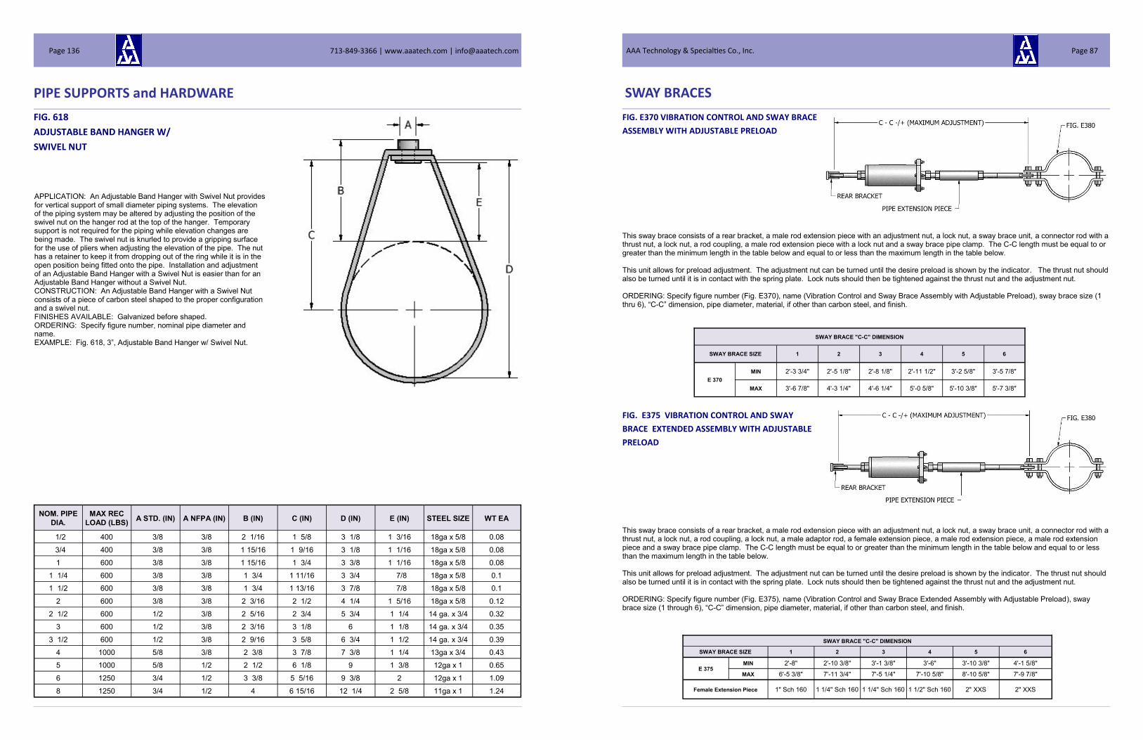
PIPE SUPPORTS and HARDWARE
FIG. 618
ADJUSTABLE BAND HANGER W/
SWIVEL NUT
NOM. PIPE
DIA.
MAX REC
LOAD (LBS) A STD. (IN) A NFPA (IN) B (IN) C (IN) D (IN) E (IN) STEEL SIZE WT EA
1/2 400 3/8 3/8 2 1/16 1 5/8 3 1/8 1 3/16 18ga x 5/8 0.08
3/4 400 3/8 3/8 1 15/16 1 9/16 3 1/8 1 1/16 18ga x 5/8 0.08
1 600 3/8 3/8 1 15/16 1 3/4 3 3/8 1 1/16 18ga x 5/8 0.08
1 1/4 600 3/8 3/8 1 3/4 1 11/16 3 3/4 7/8 18ga x 5/8 0.1
1 1/2 600 3/8 3/8 1 3/4 1 13/16 3 7/8 7/8 18ga x 5/8 0.1
2 600 3/8 3/8 2 3/16 2 1/2 4 1/4 1 5/16 18ga x 5/8 0.12
2 1/2 600 1/2 3/8 2 5/16 2 3/4 5 3/4 1 1/4 14 ga. x 3/4 0.32
3 600 1/2 3/8 2 3/16 3 1/8 6 1 1/8 14 ga. x 3/4 0.35
3 1/2 600 1/2 3/8 2 9/16 3 5/8 6 3/4 1 1/2 14 ga. x 3/4 0.39
4 1000 5/8 3/8 2 3/8 3 7/8 7 3/8 1 1/4 13ga x 3/4 0.43
5 1000 5/8 1/2 2 1/2 6 1/8 9 1 3/8 12ga x 1 0.65
6 1250 3/4 1/2 3 3/8 5 5/16 9 3/8 2 12ga x 1 1.09
8 1250 3/4 1/2 4 6 15/16 12 1/4 2 5/8 11ga x 1 1.24
APPLICATION: An Adjustable Band Hanger with Swivel Nut provides for vertical support of small diameter piping systems. The elevation of the piping system may be altered by adjusting the position of the swivel nut on the hanger rod at the top of the hanger. Temporary support is not required for the piping while elevation changes are being made. The swivel nut is knurled to provide a gripping surface for the use of pliers when adjusting the elevation of the pipe. The nut has a retainer to keep it from dropping out of the ring while it is in the open position being fitted onto the pipe. Installation and adjustment of an Adjustable Band Hanger with a Swivel Nut is easier than for an Adjustable Band Hanger without a Swivel Nut. CONSTRUCTION: An Adjustable Band Hanger with a Swivel Nut consists of a piece of carbon steel shaped to the proper configuration and a swivel nut. FINISHES AVAILABLE: Galvanized before shaped. ORDERING: Specify figure number, nominal pipe diameter and name. EXAMPLE: Fig. 618, 3”, Adjustable Band Hanger w/ Swivel Nut.
713-849-3366 | www.aaatech.com | [email protected] Page 136
SWAY BRACES
FIG. E370 VIBRATION CONTROL AND SWAY BRACE
ASSEMBLY WITH ADJUSTABLE PRELOAD
FIG. E375 VIBRATION CONTROL AND SWAY
BRACE EXTENDED ASSEMBLY WITH ADJUSTABLE
PRELOAD
This sway brace consists of a rear bracket, a male rod extension piece with an adjustment nut, a lock nut, a sway brace unit, a connector rod with a thrust nut, a lock nut, a rod coupling, a male rod extension piece with a lock nut and a sway brace pipe clamp. The C-C length must be equal to or greater than the minimum length in the table below and equal to or less than the maximum length in the table below. This unit allows for preload adjustment. The adjustment nut can be turned until the desire preload is shown by the indicator. The thrust nut should also be turned until it is in contact with the spring plate. Lock nuts should then be tightened against the thrust nut and the adjustment nut. ORDERING: Specify figure number (Fig. E370), name (Vibration Control and Sway Brace Assembly with Adjustable Preload), sway brace size (1 thru 6), “C-C” dimension, pipe diameter, material, if other than carbon steel, and finish.
This sway brace consists of a rear bracket, a male rod extension piece with an adjustment nut, a lock nut, a sway brace unit, a connector rod with a thrust nut, a lock nut, a rod coupling, a lock nut, a male adaptor rod, a female extension piece, a male rod extension piece, a male rod extension piece and a sway brace pipe clamp. The C-C length must be equal to or greater than the minimum length in the table below and equal to or less than the maximum length in the table below. This unit allows for preload adjustment. The adjustment nut can be turned until the desire preload is shown by the indicator. The thrust nut should also be turned until it is in contact with the spring plate. Lock nuts should then be tightened against the thrust nut and the adjustment nut. ORDERING: Specify figure number (Fig. E375), name (Vibration Control and Sway Brace Extended Assembly with Adjustable Preload), sway brace size (1 through 6), “C-C” dimension, pipe diameter, material, if other than carbon steel, and finish.
SWAY BRACE "C-C" DIMENSION
SWAY BRACE SIZE 1 2 3 4 5 6
E 370
MIN 2'-3 3/4" 2'-5 1/8" 2'-8 1/8" 2'-11 1/2" 3'-2 5/8" 3'-5 7/8"
MAX 3'-6 7/8" 4'-3 1/4" 4'-6 1/4" 5'-0 5/8" 5'-10 3/8" 5'-7 3/8"
SWAY BRACE "C-C" DIMENSION
SWAY BRACE SIZE 1 2 3 4 5 6
E 375 MIN 2'-8" 2'-10 3/8" 3'-1 3/8" 3'-6" 3'-10 3/8" 4'-1 5/8"
MAX 6'-5 3/8" 7'-11 3/4" 7'-5 1/4" 7'-10 5/8" 8'-10 5/8" 7'-9 7/8"
Female Extension Piece 1" Sch 160 1 1/4" Sch 160 1 1/4" Sch 160 1 1/2" Sch 160 2" XXS 2" XXS
AAA Technology & Specialties Co., Inc. Page 87

SWAY BRACES
FIG. 380 PIPE CLAMP FOR SWAY BRACE ASSEM-
BLY FIGS. E355, E360, E370 and E375
APPLICATION: These pipe clamps are for use with Sway Brace Assemblies Figs. E355, E360, E370, & E375. FEATURES: • Maximum design temperature is 650°F • Design angle maximum is 5° • SELECTING THE CORRECT SWAY STRUT CLAMP: Once the sway brace assembly has been properly sized and selected, the clamp can be easily specified by stating the figure number of the clamp followed by a dash and the sway brace size (1-6). CONSTRUCTION: A-36 Carbon Steel, Special materials available on request. FINISHES AVAILABLE: Carbon Steel - Black, Painted or Hot Dip Galvanized. ORDERING: Specify name (Pipe Clamp for Sway Brace Assembly), Fig. E380 - sway brace size (0-6), pipe diameter, material, if other than carbon steel, and finish. EXAMPLE: Pipe Clamp for Sway Brace Assembly, Fig. E380–4, 12” Pipe Dia., HDG.
NOM. PIPE DIA.
(IN)
CLAMP TAKE OUT DIMENSION "K" IN INCHES FOR
SWAY BRACE ASSEMBLIES E355, E360, E370 & E375
SPECIFY PART NUMBER E380- FOLLOWED BY THE SWAY BRACE SIZE
1 2 3 4 5 6
1 5 3/4
1 1/4 5 7/8 5 7/8 6 1/4
1 1/2 6 6 6 3/8 6 1/2
2 6 1/4 6 1/4 6 5/8 6 3/4 6 3/4 6 3/4
2 1/2 6 1/2 6 1/2 6 7/8 7 7 7
3 6 3/4 6 3/4 7 1/8 7 1/4 7 1/4 7 1/4
3 1/2 7 7 7 3/8 7 1/2 7 1/2 7 1/2
4 7 1/4 7 1/4 7 5/8 7 3/4 7 3/4 7 3/4
5 7 7/8 8 1/4 8 3/8 8 3/8 8 3/8
6 8 3/8 8 3/4 8 7/8 8 7/8 8 7/8
8 9 3/8 9 3/4 9 7/8 9 7/8 9 7/8
10 10 3/8 10 3/4 10 7/8 10 7/8 10 7/8
12 11 3/8 11 3/4 11 7/8 11 7/8 11 7/8
14 12 12 3/8 12 1/2 12 1/2 12 1/2
16 13 13 3/8 13 1/2 13 1/2 13 1/2
18 14 14 3/8 14 1/2 14 1/2 14 1/2
20 15 15 3/8 15 1/2 15 1/2 15 1/2
22 16 16 3/8 16 1/2 16 1/2 16 1/2
24 17 17 3/8 17 1/2 17 1/2 17 1/2
26 18 3/8 18 1/2 18 1/2 18 1/2
28 19 3/8 19 1/2 19 1/2 19 3/4
30 20 3/8 20 1/2 20 1/2 20 3/4
32 21 1/2 21 1/2 21 3/4
34 22 1/2 22 1/2 22 3/4
36 23 1/2 23 1/2 23 7/8
38 24 1/2 25 3/8
40 25 1/2 26 3/8
42 26 3/4 27 3/8
713-849-3366 | www.aaatech.com | [email protected] Page 88
PIPE SUPPORTS and HARDWARE
FIG. 615
ADJUSTABLE BAND HANGER
NOM. PIPE
DIA.
MAX REC
LOAD (LBS) A STD. (IN) B (IN) C (IN) D (IN) E (IN) STEEL SIZE WT EA
3/8 610 3/8 1 3/16 2 1/4 2 5/8 1 7/16 16 ga. x 7/8 0.10
1/2 610 3/8 1 3/16 2 1/8 2 5/8 13/16 16 ga. x 7/8 0.10
3/4 610 3/8 1 1/8 2 2 5/8 3/4 16 ga. x 7/8 0.10
1 610 3/8 1 5/16 2 1/8 2 7/8 1 16 ga. x 7/8 0.12
1 1/4 610 3/8 1 3/8 2 1/2 3 3/8 1 1/16 16 ga. x 7/8 0.12
1 1/2 610 3/8 1 9/16 2 1/2 3 1/2 1 1/4 16 ga. x 7/8 0.14
2 610 3/8 1 3/4 2 1/2 3 3/4 1 7/16 14 ga. x 1 0.16
2 1/2 970 1/2 1 5/8 3 1/2 5 1 1/8 14 ga. x 1 0.28
3 970 1/2 1 1/2 3 5/8 5 1/2 1 1/8 1/8 x 1 0.38
3 1/2 970 1/2 1 1/2 4 5/8 6 3/4 1 1/8 1/8 x 1 0.42
4 1130 5/8 1 1/2 4 3/8 6 3/4 1 1/8 1/8 x 1 1/4 0.60
5 1130 5/8 2 3/16 5 5/8 8 1/2 1 3/4 1/8 x 1 1/4 0.70
6 1600 3/4 2 3/8 5 7/8 9 1/4 1 13/16 1/8 x 1 1/2 1.34
8 1800 3/4 2 3/8 7 7/8 12 1/4 1 5/8 1/8 x 1 3/4 1.64
APPLICATION: An Adjustable Band Hanger without Swivel Nut pro-vides for vertical support of small diameter piping systems. The ele-vation of the piping system may be altered by adjusting the position of the hex nuts on the hanger rod at the top of the hanger. Temporary support is not required for the piping while elevation changes are being made. CONSTRUCTION: An Adjustable Band Hanger without a swivel nut consists of a piece of carbon steel shaped to the proper configuration. NOTE: Fig. 615 does not include nuts as shown in picture. FINISHES AVAILALE: Galvanized before shaped. ORDERING: Specify figure number, nominal pipe diameter and name. EXAMPLE: Fig. 615, 4”, Adjustable Band Hanger w/o Swivel Nut.
AAA Technology & Specialties Co., Inc. Page 135
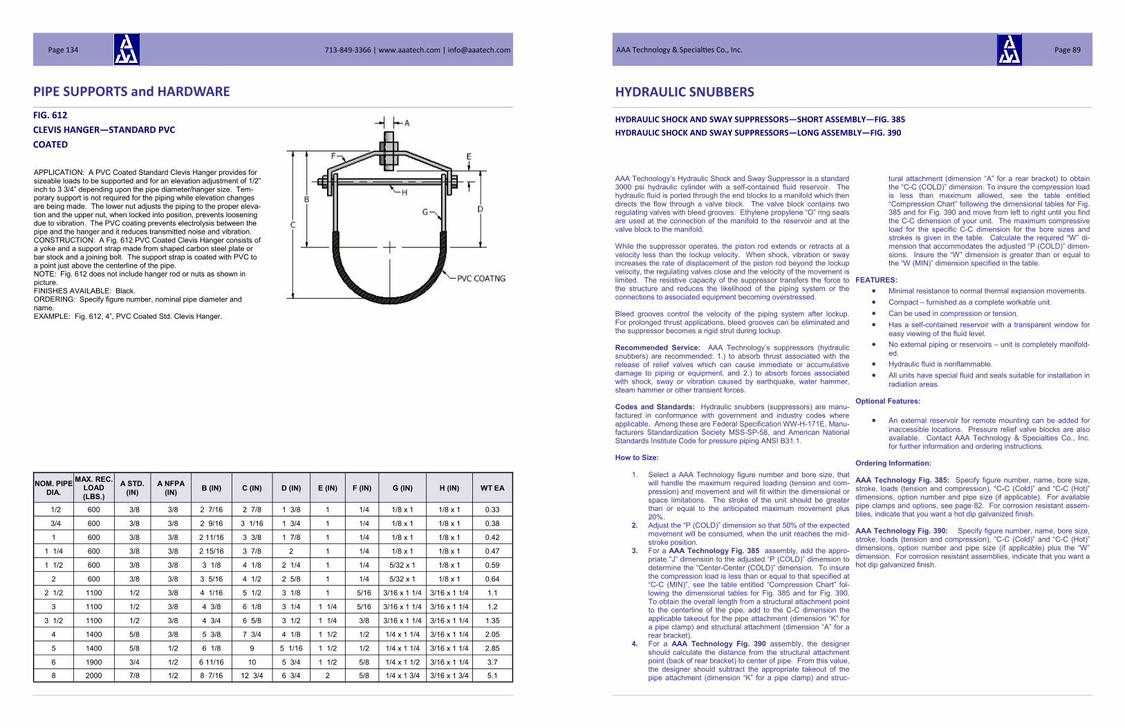
PIPE SUPPORTS and HARDWARE
FIG. 612
CLEVIS HANGER—STANDARD PVC
COATED
APPLICATION: A PVC Coated Standard Clevis Hanger provides for sizeable loads to be supported and for an elevation adjustment of 1/2” inch to 3 3/4” depending upon the pipe diameter/hanger size. Tem-porary support is not required for the piping while elevation changes are being made. The lower nut adjusts the piping to the proper eleva-tion and the upper nut, when locked into position, prevents loosening due to vibration. The PVC coating prevents electrolysis between the pipe and the hanger and it reduces transmitted noise and vibration. CONSTRUCTION: A Fig. 612 PVC Coated Clevis Hanger consists of a yoke and a support strap made from shaped carbon steel plate or bar stock and a joining bolt. The support strap is coated with PVC to a point just above the centerline of the pipe. NOTE: Fig. 612 does not include hanger rod or nuts as shown in picture. FINISHES AVAILABLE: Black. ORDERING: Specify figure number, nominal pipe diameter and name. EXAMPLE: Fig. 612, 4”, PVC Coated Std. Clevis Hanger.
NOM. PIPE
DIA.
MAX. REC. LOAD
(LBS.)
A STD.
(IN)
A NFPA
(IN) B (IN) C (IN) D (IN) E (IN) F (IN) G (IN) H (IN) WT EA
1/2 600 3/8 3/8 2 7/16 2 7/8 1 3/8 1 1/4 1/8 x 1 1/8 x 1 0.33
3/4 600 3/8 3/8 2 9/16 3 1/16 1 3/4 1 1/4 1/8 x 1 1/8 x 1 0.38
1 600 3/8 3/8 2 11/16 3 3/8 1 7/8 1 1/4 1/8 x 1 1/8 x 1 0.42
1 1/4 600 3/8 3/8 2 15/16 3 7/8 2 1 1/4 1/8 x 1 1/8 x 1 0.47
1 1/2 600 3/8 3/8 3 1/8 4 1/8 2 1/4 1 1/4 5/32 x 1 1/8 x 1 0.59
2 600 3/8 3/8 3 5/16 4 1/2 2 5/8 1 1/4 5/32 x 1 1/8 x 1 0.64
2 1/2 1100 1/2 3/8 4 1/16 5 1/2 3 1/8 1 5/16 3/16 x 1 1/4 3/16 x 1 1/4 1.1
3 1100 1/2 3/8 4 3/8 6 1/8 3 1/4 1 1/4 5/16 3/16 x 1 1/4 3/16 x 1 1/4 1.2
3 1/2 1100 1/2 3/8 4 3/4 6 5/8 3 1/2 1 1/4 3/8 3/16 x 1 1/4 3/16 x 1 1/4 1.35
4 1400 5/8 3/8 5 3/8 7 3/4 4 1/8 1 1/2 1/2 1/4 x 1 1/4 3/16 x 1 1/4 2.05
5 1400 5/8 1/2 6 1/8 9 5 1/16 1 1/2 1/2 1/4 x 1 1/4 3/16 x 1 1/4 2.85
6 1900 3/4 1/2 6 11/16 10 5 3/4 1 1/2 5/8 1/4 x 1 1/2 3/16 x 1 1/4 3.7
8 2000 7/8 1/2 8 7/16 12 3/4 6 3/4 2 5/8 1/4 x 1 3/4 3/16 x 1 3/4 5.1
713-849-3366 | www.aaatech.com | [email protected] Page 134
AAA Technology’s Hydraulic Shock and Sway Suppressor is a standard 3000 psi hydraulic cylinder with a self-contained fluid reservoir. The hydraulic fluid is ported through the end blocks to a manifold which then directs the flow through a valve block. The valve block contains two regulating valves with bleed grooves. Ethylene propylene “O” ring seals are used at the connection of the manifold to the reservoir and at the valve block to the manifold. While the suppressor operates, the piston rod extends or retracts at a velocity less than the lockup velocity. When shock, vibration or sway increases the rate of displacement of the piston rod beyond the lockup velocity, the regulating valves close and the velocity of the movement is limited. The resistive capacity of the suppressor transfers the force to the structure and reduces the likelihood of the piping system or the connections to associated equipment becoming overstressed. Bleed grooves control the velocity of the piping system after lockup. For prolonged thrust applications, bleed grooves can be eliminated and the suppressor becomes a rigid strut during lockup. Recommended Service: AAA Technology’s suppressors (hydraulic snubbers) are recommended: 1.) to absorb thrust associated with the release of relief valves which can cause immediate or accumulative damage to piping or equipment, and 2.) to absorb forces associated with shock, sway or vibration caused by earthquake, water hammer, steam hammer or other transient forces. Codes and Standards: Hydraulic snubbers (suppressors) are manu-factured in conformance with government and industry codes where applicable. Among these are Federal Specification WW-H-171E, Manu-facturers Standardization Society MSS-SP-58, and American National Standards Institute Code for pressure piping ANSI B31.1. How to Size:
1. Select a AAA Technology figure number and bore size, that
will handle the maximum required loading (tension and com-pression) and movement and will fit within the dimensional or space limitations. The stroke of the unit should be greater than or equal to the anticipated maximum movement plus 20%.
2. Adjust the “P (COLD)” dimension so that 50% of the expected movement will be consumed, when the unit reaches the mid-stroke position.
3. For a AAA Technology Fig. 385 assembly, add the appro-priate “J” dimension to the adjusted “P (COLD)” dimension to determine the “Center-Center (COLD)” dimension. To insure the compression load is less than or equal to that specified at “C-C (MIN)”, see the table entitled “Compression Chart” fol-lowing the dimensional tables for Fig. 385 and for Fig. 390. To obtain the overall length from a structural attachment point to the centerline of the pipe, add to the C-C dimension the applicable takeout for the pipe attachment (dimension “K” for a pipe clamp) and structural attachment (dimension “A” for a rear bracket).
4. For a AAA Technology Fig. 390 assembly, the designer should calculate the distance from the structural attachment point (back of rear bracket) to center of pipe. From this value, the designer should subtract the appropriate takeout of the pipe attachment (dimension “K” for a pipe clamp) and struc-
tural attachment (dimension “A” for a rear bracket) to obtain the “C-C (COLD)” dimension. To insure the compression load is less than maximum allowed, see the table entitled “Compression Chart” following the dimensional tables for Fig. 385 and for Fig. 390 and move from left to right until you find the C-C dimension of your unit. The maximum compressive load for the specific C-C dimension for the bore sizes and strokes is given in the table. Calculate the required “W” di-mension that accommodates the adjusted “P (COLD)” dimen-sions. Insure the “W” dimension is greater than or equal to the “W (MIN)” dimension specified in the table.
FEATURES:
Minimal resistance to normal thermal expansion movements.
Compact – furnished as a complete workable unit.
Can be used in compression or tension.
Has a self-contained reservoir with a transparent window for
easy viewing of the fluid level.
No external piping or reservoirs – unit is completely manifold-
ed.
Hydraulic fluid is nonflammable.
All units have special fluid and seals suitable for installation in
radiation areas. Optional Features:
An external reservoir for remote mounting can be added for
inaccessible locations. Pressure relief valve blocks are also available. Contact AAA Technology & Specialties Co., Inc. for further information and ordering instructions.
Ordering Information: AAA Technology Fig. 385: Specify figure number, name, bore size, stroke, loads (tension and compression), “C-C (Cold)” and “C-C (Hot)” dimensions, option number and pipe size (if applicable). For available pipe clamps and options, see page 82. For corrosion resistant assem-blies, indicate that you want a hot dip galvanized finish. AAA Technology Fig. 390: Specify figure number, name, bore size, stroke, loads (tension and compression), “C-C (Cold)” and “C-C (Hot)” dimensions, option number and pipe size (if applicable) plus the “W” dimension. For corrosion resistant assemblies, indicate that you want a hot dip galvanized finish.
HYDRAULIC SNUBBERS
HYDRAULIC SHOCK AND SWAY SUPPRESSORS—SHORT ASSEMBLY—FIG. 385
HYDRAULIC SHOCK AND SWAY SUPPRESSORS—LONG ASSEMBLY—FIG. 390
AAA Technology & Specialties Co., Inc. Page 89

HYDRAULIC SNUBBERS
FIG. 385 HYDRAULIC SNUBBER
SHORT ASSEMBLY
CYLINDER MAX. RATED
LOAD (LBS)
REAR BRACKET
W L4
L5
M
THREAD C-C MIN
**
R
MAX
GAP
G
NOMINAL PIN/STUD
DIA. P BORE
SIZE STROKE
WEIGHT
(LBS)
TAKE OUT
L3 H MIN MID MAX
LENGTH
L6
SIZE
H2
3/4 5 738 19 1 1/4 1 1/4 1 1/4 1 5/8 15 7/8 18 3/8 20 7/8 1 7/16 1 5/8 1/2-20 NF-3A 17 1/2 3/4 9/16 3/8
3/4 10 738 24 1 1/4 1 1/4 1 1/4 1 5/8 23 3/8 23 3/8 33 3/8 1 7/16 1 5/8 1/2-20 NF-3A 25 3/4 9/16 3/8
1 5 1434 23 1 3/4 1 1/2 1 1/4 2 1/8 16 3/4 19 1/4 21 3/4 1 11/16 1 3/4 5/8-18 NF-3A 18 7/8 1 21/32 1/2
1 10 1434 28 1 3/4 1 1/2 1 1/4 2 1/8 24 1/4 29 1/4 34 1/4 1 11/16 1 3/4 5/8-18 NF-3A 26 3/8 1 21/32 1/2
1 1/2 5 3900 31 2 1/4 2 1 1/2 2 3/4 18 7/8 21 3/8 23 7/8 3 5/16 1 3/8 3/4-16 UNF 21 5/8 1 1/4 25/32 5/8
1 1/2 10 3900 38 2 1/4 2 1 1/2 2 3/4 26 3/8 31 3/8 36 3/8 3 5/16 1 3/8 3/4-16 UNF 29 1/8 1 1/4 25/32 5/8
1 1/2 15 3900 44 2 1/4 2 1 1/2 2 3/4 33 7/8 41 3/8 48 7/8 3 5/16 1 3/8 3/4-16 UNF 36 5/8 1 1/4 25/32 5/8
1 1/2 20 3900 51 2 1/4 2 1 1/2 2 3/4 41 3/8 51 3/8 61 3/8 3 5/16 1 3/8 3/4-16 UNF 44 1/8 1 1/4 25/32 5/8
2 5 7000 42 2 1/2 2 1/4 2 3 3/8 19 1/8 21 5/8 24 1/8 3 9/16 1 3/4 1 - 14 NF 22 1/2 1 1/2 29/32 3/4
2 10 7000 51 2 1/2 2 1/4 2 3 3/8 26 5/8 31 5/8 36 5/8 3 9/16 1 3/4 1 - 14 NF 30 1 1/2 29/32 3/4
2 15 7000 60 2 1/2 2 1/4 2 3 3/8 34 1/8 41 5/8 49 1/8 3 9/16 1 3/4 1 - 14 NF 37 1/2 1 1/2 29/32 3/4
2 20 7000 69 2 1/2 2 1/4 2 3 3/8 41 5/8 51 5/8 61 5/8 3 9/16 1 3/4 1 - 14 NF 45 1 1/2 29/32 3/4
2 1/2 5 11000 55 2 3/4 2 5/8 2 1/4 3 1/2 20 5/8 23 1/8 25 5/8 3 13/16 2 1/8 1 1/4 - 12 UNF 24 1/8 1 1/2 1 1/32 1
2 1/2 10 11000 66 2 3/4 2 5/8 2 1/4 3 1/2 28 1/8 33 1/8 38 1/8 3 13/16 2 1/8 1 1/4 - 12 UNF 31 5/8 1 1/2 1 1/32 1
2 1/2 15 11000 77 2 3/4 2 5/8 2 1/4 3 1/2 35 5/8 43 1/8 50 5/8 3 13/16 2 1/8 1 1/4 - 12 UNF 39 1/8 1 1/2 1 1/32 1
2 1/2 20 11000 88 2 3/4 2 5/8 2 1/4 3 1/2 43 1/8 53 1/8 63 1/8 3 13/16 2 1/8 1 1/4 - 12 UNF 46 5/8 1 1/2 1 1/32 1
3 1/4 5 17600 95 3 1/2 3 3/4 3 4 25 27 1/2 30 4 5/16 2 7/8 1 3/4 - 12 UN 29 2 1/4 1 19/32 1 1/4
3 1/4 10 17600 112 3 1/2 3 3/4 3 4 32 7/8 37 7/8 42 7/8 4 5/16 2 7/8 1 3/4 - 12 UN 36 7/8 2 1/4 1 19/32 1 1/4
3 1/4 15 17600 130 3 1/2 3 3/4 3 4 40 3/4 48 1/4 55 3/4 4 5/16 2 7/8 1 3/4 - 12 UN 44 3/4 2 1/4 1 19/32 1 1/4
3 1/4 20 17600 147 3 1/2 3 3/4 3 4 48 5/8 58 5/8 68 5/8 4 5/16 2 7/8 1 3/4 - 12 UN 52 5/8 2 1/4 1 19/32 1 1/4
4 5 28200 126 4 1/2 5 3 3/4 4 1/4 25 3/4 28 1/4 30 3/4 4 9/16 3 1/4 2 - 12 UN 30 2 1/2 1 25/32 1 1/2
4 10 28200 147 4 1/2 5 3 3/4 4 1/4 33 1/4 38 1/4 43 1/4 4 9/16 3 1/4 2 - 12 UN 37 1/2 2 1/2 1 25/32 1 1/2
4 15 28200 168 4 1/2 5 3 3/4 4 1/4 40 3/4 48 1/4 55 3/4 4 9/16 3 1/4 2 - 12 UN 45 2 1/2 1 25/32 1 1/2
4 20 28200 189 4 1/2 5 3 3/4 4 1/4 48 1/4 58 1/4 68 1/4 4 9/16 3 1/4 2 - 12 UN 52 1/2 2 1/2 1 25/32 1 1/2
5 5 44000 220 5 7 7 5 1/4 28 3/8 31 1/4 33 3/4 5 5/16 4 2 1/2 - 12 UN 34 3 2 7/32 1 3/4
5 10 44000 253 5 7 7 5 1/4 36 1/4 41 1/4 46 1/4 5 5/16 4 2 1/2 - 12 UN 41 1/2 3 2 7/32 1 3/4
5 15 44000 287 5 7 7 5 1/4 43 3/4 51 1/4 58 3/4 5 5/16 4 2 1/2 - 12 UN 49 3 2 7/32 1 3/4
5 20 44000 321 5 7 7 5 1/4 51 1/4 61 1/4 71 1/4 5 5/16 4 2 1/2 - 12 UN 56 1/2 3 2 7/32 1 3/4
6 5 63600 332 5 3/4 8 8 5 3/4 31 5/8 34 1/8 36 5/8 5 13/16 4 3/4 3 - 12 UN 37 3/8 3 1/4 2 13/32 2
6 10 63600 376 5 3/4 8 8 5 3/4 39 1/8 44 1/8 49 1/8 5 13/16 4 3/4 3 - 12 UN 44 7/8 3 1/4 2 13/32 2
6 15 63600 421 5 3/4 8 8 5 3/4 46 5/8 54 1/8 61 5/8 5 13/16 4 3/4 3 - 12 UN 52 3/8 3 1/4 2 13/32 2
6 20 63600 465 5 3/4 8 8 5 3/4 54 1/8 64 1/8 74 1/8 5 13/16 4 3/4 3 - 12 UN 59 7/8 3 1/4 2 13/32 2
8 5 113000 684 7 1/2 10 10 8 38 40 1/2 43 6 13/16 6 1/4 4 - 12 UN 46 4 3/4 3 7/16 2 3/4
8 10 113000 755 7 1/2 10 10 8 45 1/2 50 1/2 55 1/2 6 13/16 6 1/4 4 - 12 UN 53 1/2 4 3/4 3 7/16 2 3/4
8 15 113000 828 7 1/2 10 10 8 53 60 1/2 68 6 13/16 6 1/4 4 - 12 UN 61 4 3/4 3 7/16 2 3/4
8 20 113000 900 7 1/2 10 10 8 60 1/2 70 1/2 50 1/2 6 13/16 6 1/4 4 - 12 UN 68 1/2 4 3/4 3 7/16 2 3/4
10 5 187900 1308 9 1/2 13 13 9 1/2 45 1/16 47 9/16 50 1/16 8 3/8 7 4 1/2 - 12 UN 54 9/16 6 1/3 4 5/16 3 3/4
10 10 187900 1419 9 1/2 13 13 9 1/2 52 9/16 57 9/16 62 9/16 8 3/8 7 4 1/2 - 12 UN 62 1/16 6 1/3 4 5/16 3 3/4
10 15 187900 1529 9 1/2 13 13 9 1/2 60 1/16 67 9/16 75 1/16 8 3/8 7 4 1/2 - 12 UN 69 9/16 6 1/3 4 5/16 3 3/4
10 20 187900 1640 9 1/2 13 13 9 1/2 57 9/16 77 9/16 87 9/16 8 3/8 7 4 1/2 - 12 UN 77 1/16 6 1/3 4 5/16 3 3/4
713-849-3366 | www.aaatech.com | [email protected] Page 90
PIPE SUPPORTS and HARDWARE
FIG. 609
ELONGATED CLEVIS HANGER
APPLICATION: An Elongated Clevis Hanger for Insulated Lines is used to support insulated piping and will accommodate a 2” thickness of insulation on 3/4” to 1 1/2” piping and a 4” thickness of insulation on 2” and larger piping. The insulation is applied around and over the clamp itself. An Elongated Clevis Hanger provides for elevation ad-justment of 1 1/16” to 3” depending upon the pipe size, hanger size and insulation thickness. Temporary support is not required for the piping while elevation changes are being made. CONSTRUCTION: A Fig. 609 Elongated Clevis Hanger for Insulated Lines consists of a yoke and a support strap made from shaped car-bon steel plate or bar stock and a joining bolt. NOTE: Fig. 609 does not include hanger rod or nuts as shown in the picture. FINISHES AVAILABLE: Black, Hot Dip Galvanized, Electro-Plated or Painted. ORDERING: Specify figure number, nominal pipe diameter, name and finish, if other than black. EXAMPLE: Fig. 609, 8”, Elongated Clevis Hanger for Insulated Lines, HDG.
NOM. PIPE
DIA.
MAX. REC.
LOAD (LBS.)
A
(IN)
B
(IN)
C
(IN)
D
(IN)
E
(IN)
F
(IN)
G
(IN) WT EA
1/2 610 3/8 3 13/16 4 1/4 3 7/16 13ga x 7/8 12ga x 7/8 0.30
3/4 610 3/8 3 3/4 4 3/16 2 15/16 7/16 13ga x 7/8 12ga x 7/8 0.33
1 610 3/8 4 1/8 4 3/4 3 5/16 5/8 13ga x 7/8 12ga x 7/8 0.34
1 1/4 610 3/8 4 7/16 5 1/4 3 5/8 7/8 13ga x 7/8 12ga x 7/8 0.39
1 1/2 610 3/8 4 3/4 5 3/4 3 15/16 1 1/16 12ga x 7/8 12ga x 7/8 0.47
2 610 3/8 7 1/4 8 7/16 6 7/16 1 1/4 12ga x 7/8 12ga x 7/8 0.65
2 1/2 1130 1/2 8 13/16 10 3/16 7 3/4 1 15/16 9ga x 1 3/16 10ga x 1 3/16 1.25
3 1130 1/2 9 10 3/4 7 15/16 1 3/4 9ga x 1 3/16 10ga x 1 3/16 1.34
4 1430 5/8 10 1/8 12 3/8 8 13/16 2 1/8 8ga x 1 3/16 10ga x 1 3/16 1.92
5 1430 5/8 9 7/8 12 9/16 8 7/16 1 7/16 4ga x1 1/4 8ga x 1 1/4 2.58
6 1940 3/4 10 7/8 14 1/8 9 1/4 1 3/4 3ga x 1 1/2 8ga x 1 1/2 3.36
8 2000 3/4 12 1/4 16 9/16 10 7/16 1 7/8 3ga x 1 3/4 8ga x 1 3/4 5.08
10 3600 7/8 14 1/2 19 7/8 12 1/2 2 1/4 3/8 x 1 3/4 3ga x 1 3/4 9.08
12 3800 7/8 15 7/8 22 1/4 13 39/50 2 13/16 3/8 x 2 3ga x 2 11.54
14 4200 1 19 1/2 26 1/2 15 7/8 2 1/8 1/2 x 2 1/4 x 2 14.80
16 4800 1 23 31 17 1/8 2 5/8 1/2 x 2 1/2 1/4 x 2 1/2 21.00
18 4800 1 24 3/4 33 3/4 19 1/4 3 1/4 1/2 x 2 1/2 1/4 x 2 1/2 24.35
*Please refer to F. 603 for Dimension H.
AAA Technology & Specialties Co., Inc. Page 133

PIPE SUPPORTS and HARDWARE
FIG. 606
CLEVIS HANGER W/ WELDED SHIELD
PIPE SIZE THICKNESS OF PIPE INSULATION (IN)
1/2" 1" 1 1/2" 2" 2 1/2" 3"
1/2 1 1/2 2 1/2 3 1/2 5 6 7
3/4 2 3 3 1/2 5 6 7
1 2 3 4 5 6 7
1 1/4 2 1/2 3 1/2 4 5 6 7
1 1/2 2 1/2 3 1/2 5 6 7 8
2 3 4 5 6 7 8
2 1/2 3 1/2 5 6 7 8 10
3 4 5 6 7 8 10
3 1/2 5 6 7 8 10 10
4 5 6 7 8 10 10
5 6 7 8 10 10 12
6 7 8 10 10 12 12
8 10 10 12 12 14 16
10 12 12 14 16 16 18
12 14 16 16 18 18 20
14 16 16 18 18 20 20
16 18 18 20 20 24 24
APPLICATION: Fig. 606 Clevis Hangers with Welded Shields are used to support insulated piping while preventing the crushing of the insulation or vapor barrier by the clevis hangers. Elevation adjust-ment is provided for as with a Standard Clevis Hanger. Temporary support is not required for the piping while elevation changes are being made. CONSTRUCTION: A Fig. 606 Clevis Hanger with Welded Shield is a combination of the Fig. 603 Clevis Hanger and the Fig. 800 Insulation Protection Shield. The Insulation Protection Shield is rolled carbon steel plate and the Clevis Hanger consists of a yoke and a support strap made from shaped carbon steel plate or bar stock and a joining bolt. NOTE: Fig. 606 does not include hanger rod or nuts as shown in the picture. FINISHES AVAILABLE: Black, Hot Dip Galvanized, Electro-Plated or Painted. ORDERING: Specify figure number, nominal pipe diameter from chart, name and finish, if other than black. EXAMPLE: Fig. 606, 10”, Clevis Hanger with Welded Shield, HDG.
713-849-3366 | www.aaatech.com | [email protected] Page 132
HYDRAULIC SNUBBERS
FIG. 390 HYDRAULIC SNUBBER ASSEMBLY
CYLINDER MAX* RATED LOADS
(LBS)
REAR BRACKET L5
F M
C-C MIN
**
FEMALE PIPE EXT.
PIECE
R
MAX
GAP
G
NOM. PIN/STUD
DIA.
P
L4
MIN
THREAD
BORE
SIZE
STRO
KE
TAKE OUT
H W MIN MID MAX LENGTH
L6
SIZE
H2
3/4 5 738 1 1/4 1 1/4 1 1/4 15 7/8 18 3/8 20 7/8 5 1/2 1 7/16 29 5/8 1/2 - STD 3/4 9/16 3/8 8 1/4 1 5/8 1/2-20 NF-3A
3/4 10 738 1 1/4 1 1/4 1 1/4 23 3/8 23 3/8 33 3/8 5 1/2 1 7/16 37 1/8 1/2 - STD 3/4 9/16 3/8 8 1/4 1 5/8 1/2-20 NF-3A
1 5 1434 1 3/4 1 1/2 1 1/4 16 3/4 19 1/4 21 3/4 5 3/4 1 11/16 31 1/8 3/4 STD 1 21/32 1/2 8 5/8 1 3/4 5/8-18 NF-3A
1 10 1434 1 3/4 1 1/2 1 1/4 24 1/4 29 1/4 34 1/4 5 3/4 1 11/16 38 5/8 3/4 STD 1 21/32 1/2 8 5/8 1 3/4 5/8-18 NF-3A
1 1/2 5 3900 2 1/4 2 1 1/2 18 7/8 21 3/8 23 7/8 6 1/4 3 5/16 34 1 1/4 XS 1 1/4 25/32 5/8 8 7/8 1 3/8 3/4 - 16 UNF
1 1/2 10 3900 2 1/4 2 1 1/2 26 3/8 31 3/8 36 3/8 6 1/4 3 5/16 41 1/2 1 1/4 XS 1 1/4 25/32 5/8 8 7/8 1 3/8 3/4 - 16 UNF
1 1/2 15 3900 2 1/4 2 1 1/2 33 7/8 41 3/8 48 7/8 6 1/4 3 5/16 49 1 1/4 XS 1 1/4 25/32 5/8 8 7/8 1 3/8 3/4 - 16 UNF
1 1/2 20 3900 2 1/4 2 1 1/2 41 3/8 51 3/8 61 3/8 6 1/4 3 5/16 56 1/2 1 1/4 XS 1 1/4 25/32 5/8 8 7/8 1 3/8 3/4 - 16 UNF
2 5 7000 2 1/2 2 1/4 2 19 1/8 21 5/8 24 1/8 6 7/8 3 9/16 36 1/4 1 1/2 XS 1 1/2 29/32 3/4 9 1/4 1 3/4 1 - 14 NF
2 10 7000 2 1/2 2 1/4 2 26 5/8 31 5/8 36 5/8 6 7/8 3 9/16 42 3/4 1 1/2 XS 1 1/2 29/32 3/4 9 1/4 1 3/4 1 - 14 NF
2 15 7000 2 1/2 2 1/4 2 34 1/8 41 5/8 49 1/8 6 7/8 3 9/16 50 1/4 1 1/2 XS 1 1/2 29/32 3/4 9 1/4 1 3/4 1 - 14 NF
2 20 7000 2 1/2 2 1/4 2 41 5/8 51 5/8 61 5/8 6 7/8 3 9/16 57 3/4 1 1/2 XS 1 1/2 29/32 3/4 9 1/4 1 3/4 1 - 14 NF
2 1/2 5 11000 2 3/4 2 5/8 2 1/4 20 5/8 23 1/8 25 5/8 7 1/2 3 13/16 38 2XS 1 1/2 1 1/32 1 9 7/8 2 1/8 1 1/4 - 12 UNF
2 1/2 10 11000 2 3/4 2 5/8 2 1/4 28 1/8 33 1/8 38 1/8 7 1/2 3 13/16 45 1/2 2XS 1 1/2 1 1/32 1 9 7/8 2 1/8 1 1/4 - 12 UNF
2 1/2 15 11000 2 3/4 2 5/8 2 1/4 35 5/8 43 1/8 50 5/8 7 1/2 3 13/16 53 2XS 1 1/2 1 1/32 1 9 7/8 2 1/8 1 1/4 - 12 UNF
2 1/2 20 11000 2 3/4 2 5/8 2 1/4 43 1/8 53 1/8 63 1/8 7 1/2 3 13/16 60 1/2 2XS 1 1/2 1 1/32 1 9 7/8 2 1/8 1 1/4 - 12 UNF
3 1/4 5 17600 3 1/2 3 3/4 3 25 27 1/2 30 9 3/4 4 5/16 45 1/2 2 1/2 XS 2 1/4 1 19/32 1 1/4 10 3/4 2 7/8 1 3/4 - 12 UN
3 1/4 10 17600 3 1/2 3 3/4 3 32 7/8 37 7/8 42 7/8 9 3/4 4 5/16 53 3/8 2 1/2 XS 2 1/4 1 19/32 1 1/4 10 3/4 2 7/8 1 3/4 - 12 UN
3 1/4 15 17600 3 1/2 3 3/4 3 40 3/4 48 1/4 55 3/4 9 3/4 4 5/16 61 1/4 2 1/2 XS 2 1/4 1 19/32 1 1/4 10 3/4 2 7/8 1 3/4 - 12 UN
3 1/4 20 17600 3 1/2 3 3/4 3 48 5/8 58 5/8 68 5/8 9 3/4 4 5/16 69 1/8 2 1/2 XS 2 1/4 1 19/32 1 1/4 10 3/4 2 7/8 1 3/4 - 12 UN
4 5 28200 4 1/2 5 3 3/4 25 3/4 28 1/4 30 3/4 10 5/8 4 9/16 47 7/8 3XS 2 1/2 1 25/32 1 1/2 11 1/2 3 1/4 2 - 12 UN
4 10 28200 4 1/2 5 3 3/4 .33 1/4 38 1/4 43 1/4 10 5/8 4 9/16 55 3/8 3XS 2 1/2 1 25/32 1 1/2 11 1/2 3 1/4 2 - 12 UN
4 15 28200 4 1/2 5 3 3/4 40 3/4 48 1/4 55 3/4 10 5/8 4 9/16 62 7/8 3XS 2 1/2 1 25/32 1 1/2 11 1/2 3 1/4 2 - 12 UN
4 20 28200 4 1/2 5 3 3/4 48 1/4 58 1/4 68 1/4 10 5/8 4 9/16 70 3/8 3XS 2 1/2 1 25/32 1 1/2 11 1/2 3 1/4 2 - 12 UN
5 5 44000 5 7 7 28 3/8 31 1/4 33 3/4 12 3/8 5 5/16 53 3/8 4XS 3 2 7/32 1 3/4 12 1/4 4 2 1/2 - 12 UN
5 10 44000 5 7 7 36 1/4 41 1/4 46 1/4 12 3/8 5 5/16 60 7/8 4XS 3 2 7/32 1 3/4 12 1/4 4 2 1/2 - 12 UN
5 15 44000 5 7 7 43 3/4 51 1/4 58 3/4 12 3/8 5 5/16 68 3/8 4XS 3 2 7/32 1 3/4 12 1/4 4 2 1/2 - 12 UN
5 20 44000 5 7 7 51 1/4 61 1/4 71 1/4 12 3/8 5 5/16 75 7/8 4XS 3 2 7/32 1 3/4 12 1/4 4 2 1/2 - 12 UN
6 5 63600 5 3/4 8 8 31 5/8 34 1/8 36 5/8 13 1/4 5 13/16 58 5XS 3 1/4 2 13/32 2 13 1/8 4 3/4 3 - 12 UN
6 10 63600 5 3/4 8 8 39 1/8 44 1/8 49 1/8 13 1/4 5 13/16 65 1/2 5XS 3 1/4 2 13/32 2 13 1/8 4 3/4 3 - 12 UN
6 15 63600 5 3/4 8 8 46 5/8 54 1/8 61 5/8 13 1/4 5 13/16 73 5XS 3 1/4 2 13/32 2 13 1/8 4 3/4 3 - 12 UN
6 20 63600 5 3/4 8 8 54 1/8 64 1/8 74 1/8 13 1/4 5 13/16 80 1/2 5XS 3 1/4 2 13/32 2 13 1/8 4 3/4 3 - 12 UN
8 5 113000 7 1/2 10 10 38 40 1/2 43 16 6 13/16 69 1/4 6XS 4 3/4 3 7/16 2 3/4 15 1/4 6 1/4 4 - 12 UN
8 10 113000 7 1/2 10 10 45 1/2 50 1/2 55 1/2 16 6 13/16 76 3/4 6XS 4 3/4 3 7/16 2 3/4 15 1/4 6 1/4 4 - 12 UN
8 15 113000 7 1/2 10 10 53 60 1/2 68 16 6 13/16 84 1/4 6XS 4 3/4 3 7/16 2 3/4 15 1/4 6 1/4 4 - 12 UN
8 20 113000 7 1/2 10 10 60 1/2 70 1/2 80 1/2 16 6 13/16 91 3/4 6XS 4 3/4 3 7/16 2 3/4 15 1/4 6 1/4 4 - 12 UN
10 5 187900 9 1/2 13 13 45 1/16 47 9/16 50 1/16 20 1/8 8 3/8 81 15/16 8XS 6 5/16 4 5/16 3 3/4 16 3/4 7 4 1/2 - 12 UN
10 10 187900 9 1/2 13 13 52 9/16 57 9/16 62 9/16 20 1/8 8 3/8 89 7/16 8XS 6 5/16 4 5/16 3 3/4 16 3/4 7 4 1/2 - 12 UN
10 15 187900 9 1/2 13 13 60 1/16 67 9/16 75 1/16 20 1/8 8 3/8 96 15/16 8XS 6 5/16 4 5/16 3 3/4 16 3/4 7 4 1/2 - 12 UN
10 20 187900 9 1/2 13 13 67 9/16 77 9/16 87 9/16 20 1/8 8 3/8 104 7/16 8XS 6 5/16 4 5/16 3 3/4 16 3/4 7 4 1/2 - 12 UN
AAA Technology & Specialties Co., Inc. Page 91

HYDRAULIC SNUBBERS
CYLINDER
BORE
SIZE
STROKE
(IN) @MIN 32” 36” 40” 44” 48” 52” 56” 60” 64” 68” 72” 76”
3/4 5 520 275 190 125 75
1 5 1434 1100 855 710 565 465 390 345
10 765 325 215 185 140 120
CYLINDER
BORE
SIZE
STROKE
(IN) @MIN 3’ - 0” 4’ - 0” 5’ - 0” 6’ - 0” 7’ - 0” 8’ - 0” 9’ - 0” 10’ - 0” 11’ - 0” 12’ - 0” 13’ - 0” 14’ - 0” 15’ - 0”
1 1/2
5 3200 2450 1760 1180 800 560
10 1400 860 440 240
15 350 100
2
5 7000 6050 4850 3750 2800 2050 1550
10 4500 3300 2400 1650 1400
15 2300 1500 950 550
20 1400 900 450
2 1/2
5 11000 10000 8650 7400 6000 4800 3400
10 9300 8200 6700 5400 4600 3200 2600
15 6400 5000 3800 2800 2000 1600
20 3700 2600 1700 1200 900
3 1/4
5 17600 17600 17600 17600 17200 14900 12600 10200
10 17600 17600 16500 14200 12000 9900 7800
15 16800 14200 11700 8400 7700 6100 5000
20 14400 11850 9500 7600 6000 4700 4000
4
5 28200 28200 28200 28200 26350 23950 21600 19000
10 28200 27600 25200 22500 20000 17700 15400
15 25200 22250 19300 16800 14600 12450 10500
20 23000 19600 16200 14100 12000 10000 8300
5
5 44000 44000 44000 44000 43000 40400 37000 33800 30600
10 44000 43800 41100 38300 35300 32300 29100 26000
15 43400 40400 37000 33800 30600 27400 24500 21400
20 36700 32600 29100 26000 23000 20400 17800
6
5 63600 63600 63600 63600 63600 63600 61600 58200 54800
10 63600 63600 63600 61100 58800 53400 51400 47400
15 63600 60200 57600 53000 49400 45600 42000
20 60500 56200 51800 47800 43600 40000 36800
8
5 113000 113000 113000 113000 113000 113000 113000 111000 108000
10 113000 113000 113000 113000 110000 106000 102000 97500
15 113000 113000 108000 103000 98300 93500 88800
20 112500 107000 102000 96000 90000 84000 78000
10
5 159000 155000 151000 146500 142000 137500 133000 128000 123000 118000
10 148000 143300 138800 134000 129500 125000 120000 115000 110500
15 143500 131600 125500 120000 114500 109500 104000 98500
20 131000 116500 110500 104500 99000 93000 87000
FIG. 385 & FIG. 390 COMPRESSION CHART
MAXIMUM RATED COMPRESSION LOADS (LBS)**
Interpolate for lengths not listed. **Do not use unit in compression if no maximum rating is shown.
713-849-3366 | www.aaatech.com | [email protected] Page 92
PIPE SUPPORTS and HARDWARE
FIG. 603
CLEVIS HANGER—STANDARD
NOM. PIPE
DIA.
MAX. REC. LOAD
(LBS.) A STD. (IN) B (IN) C (IN) D (IN) E (IN) F (IN) G (IN) H (IN) WT EA
1/2 610 3/8 1 11/16 2 1/16 15/16 7/16 13 ga x 7/8 13 ga x 7/8 1/4 0.18
3/4 610 3/8 1 11/16 2 9/16 15/16 7/16 13 ga x 7/8 13 ga x 7/8 1/4 0.18
1 610 3/8 2 1/16 2 11/16 1 1/4 5/8 13 ga x 7/8 13 ga x 7/8 1/4 0.22
1 1/4 610 3/8 2 1/2 3 3/16 1 11/16 7/8 13 ga x 7/8 13 ga x 7/8 1/4 0.26
1 1/2 610 3/8 2 7/8 3 11/16 2 1/16 1 1/16 12 ga x 7/8 12 ga x 7/8 1/4 0.34
2 610 3/8 3 5/16 4 7/16 2 1/2 1 8/31 12 ga x 7/8 12 ga x 7/8 1/4 0.38
2 1/2 1130 1/2 4 1/2 5 7/8 3 3/8 1 15/16 9ga x 1 3/16 10ga x 1 3/16 5/16 0.86
3 1130 1/2 4 3/4 6 1/2 3 11/16 1 3/4 9ga x 1 3/16 10ga x 1 3/16 5/16 0.96
3 1/2 1130 1/2 5 7/8 7 15/16 4 13/16 2 9/16 8ga x 1 3/16 10ga x 1 3/16 3/8 1.14
4 1430 5/8 5 15/16 8 3/16 4 9/16 2 1/8 8ga x 1 3/16 10ga x 1 3/16 1/2 1.26
5 1430 5/8 5 11/16 8 7/16 4 5/16 1 7/16 4ga x1 1/4 8ga x 1 1/4 1/2 2.04
6 1940 3/4 3 13/16 10 1/8 5 3/16 1 3/4 3ga x 1 1/2 8ga x 1 1/2 1/2 2.80
7 2000 3/4 7 13/16 11 5/8 6 3/16 2 3ga x 1 1/2 8ga x 1 1/2 1/2 3.24
8 2000 3/4 8 1/16 12 7/16 6 1/4 1 7/8 3ga x 1 3/4 8ga x 1 3/4 1/2 4.46
10 3600 7/8 10 15 7/16 8 2 1/4 3/8 x 1 3/4 3ga x 1 3/4 3/4 8.06
12 3800 7/8 11 9/16 18 9 9/16 2 13/16 3/8 x 2 3ga x 2 3/4 10.37
14 4200 1 12 9/16 19 9/16 10 9/16 2 9/16 1/2 x 2 1/4 x 2 7/8 14.80
16 4600 1 13 15/16 21 15/16 11 15/16 2 13/16 1/2 x 2 1/2 1/4 x 2 1/2 1 21.00
18 4800 1 16 25 13 7/8 3 3/4 1/2 x 2 1/2 1/4 x 2 1/2 1 1/8 24.40
20 4800 1 1/4 17 1/2 27 1/2 15 1/8 3 3/4 5/8 x 3 3/8 x 3 1 1/4 47.00
24 4800 1 1/4 19 3/4 31 3/4 17 3/8 4 5/8 x 3 3/8 x 3 1 1/4 54.00
30 6000 1 1/4 24 1/8 39 1/8 21 1/2 4 3/4 5/8 x 3 3/8 x 3 1 1/4 69.50
APPLICATION: A standard Clevis Hanger provides for sizeable loads to be supported and for an elevation adjustment of 1/2” to 3 3/4” depending upon the pipe diameter/hanger size. Temporary support is not required for the piping while elevation changes are being made. The lower nut adjusts the piping to the proper elevation and the upper nut, when locked into position, prevents loosening due to vibration. CONSTRUCTION: A Fig. 603 standard Clevis Hanger consists of a yoke and a support strap made from shaped carbon steel plate or bar stock and a joining bolt. NOTE: Fig. 603 does not include hanger rod or nuts as shown in picture. FINISHES AVAILABLE: Black, Hot Dip Galvanized, Electro-Plated or Painted. ORDERING: Specify figure number, nominal pipe diameter, name, and finish, if other than black.
AAA Technology & Specialties Co., Inc. Page 131

PIPE SUPPORTS and HARDWARE
FIG. 600
CLEVIS HANGER—LIGHT DUTY
APPLICATION: A Light Duty Clevis Hanger provides for small vertical loads to be supported and for elevation adjustment of 1 1/16” to 2 1/4” depending upon the pipe diameter/hanger size. Temporary support is not required for the piping while elevation changes are being made. The lower nut adjusts the piping to the proper elevation and the upper nut, when locked into position, prevents loosening due to vibration. CONSTRUCTION: A Fig. 600 Light Duty Clevis Hanger consists of a yoke and a support strap made from shaped carbon steel plate or bar stock and a joining bolt. NOTE: Fig. 600 does not include hanger rod or nuts as shown in picture. FINISHES AVAILALE: Black, Hot Dip Galvanized, Electro-Plated or Painted. ORDERING: Specify figure number, nominal pipe diameter, name and finish, if other than black. EXAMPLE; Fig. 600, 2 1/2”, Light Duty Clevis Hanger, HDG.
NOM. PIPE
DIA.
MAX. REC. LOAD
(LBS.) A (IN) B (IN) C (IN) D (IN) E (IN)
STEEL
SIZE F
STEEL
SIZE G BOLT H (IN) WT EA
3/8 150 3/8 2 7/16 2 7/8 2 1/16 1 1/16 16 ga x 7/8 16 ga x 7/8 1/4 0.11
1/2 150 3/8 2 7/16 2 7/8 2 1/16 1 1/16 16 ga x 7/8 16 ga x 7/8 1/4 0.13
3/4 250 3/8 2 11/16 3 3/16 2 5/16 1 1/8 16 ga x 7/8 16 ga x 7/8 1/4 0.28
1 250 3/8 2 5/8 3 5/16 2 1/4 1 1/8 16 ga x 7/8 16 ga x 7/8 1/4 0.31
1 1/4 250 3/8 3 1/16 3 7/8 2 11/16 1 5/16 16 ga x 7/8 16 ga x 7/8 1/4 0.33
1 1/2 250 3/8 3 1/4 4 1/8 2 7/8 1 3/16 13 ga x 7/8 16 ga x 7/8 1/4 0.36
2 250 3/8 3 13/16 5 3 7/8 1 5/8 13 ga x 7/8 13 ga x 7/8 1/4 0.37
2 1/2 350 1/2 4 1/4 5 1/16 3 11/16 1 7/16 1/8 x 1 1/4 1/8 x 1 1/4 1/4 0.89
3 350 1/2 4 1/4 6 3 11/16 1 1/4 1/8 x 1 1/4 1/8 x 1 1/4 1/4 0.98
3 1/2 350 1/2 4 1/2 6 1/2 3 15/16 1 3/16 1/8 x 1 1/4 1/8 x 1 1/4 5/16 1.07
4 400 5/8 5 9/16 7 13/16 4 13/16 2 1/4 3/16 x 1 1/4 1/8 x 1 1/4 3/8 1.3
713-849-3366 | www.aaatech.com | [email protected] Page 130
PIPE SUPPORTS and HARDWARE
APPLICATION: All Thread Rod is the most versatile type of hanger rod. Since All Thread Rod is threaded for the entire length of the rod, it may be cut to any length and used without additional thread-ing being required. CONSTRUCTION: All Thread Rod is made of mild low carbon steel, SA-36, and is available in 6 ft., 10 ft. and 20 ft. lengths. FINISHES AVAILALE: Black, Hot Dip Galvanized, Electro-Plated or Painted. ORDERING: Specify figure number, rod diameter X rod length, name and finish, if other than black. EXAMPLE: Fig. 400, 3/8” diameter X 10 ft. long, All Thread Rod,
FIG. 403 - Right Hand Threads Both Ends FIG. 403L - Left Hand Threads Both Ends FIG. 403RL - Right Hand Threads one end, Left Hand Threads other end. APPLICATION: Machine Thread Rod is designed to be used as a hanger rod and is threaded on each end to allow adjustment of overall hanger length when used with end attachments like Fig. 424 Turnbuckles, Fig. 418 Eyenuts, etc. CONSTRUCTION: Machine Thread Rod is furnished in diameters from 3/8 inch through 4 inches. The standard thread lengths for each rod diameter are listed in the table. Machine Thread Rod can be furnished in any specified length. Machine Thread Rod shorter than 16 inches will be furnished in All Thread Rod. FINISHES AVAILABLE: Black, Hot Dip Galvanized, Electro-Plated or Painted. ORDERING: Specify figure number, rod diameter X rod length, name and finish, if other than black. EXAMPLE: Fig. 403RL, 5/8” diameter X 38” long, Machine Thread Rod, HDG.
ROD DIA
MAX. REC. LOAD LBS., 650
F
MAX. REC. LOAD LBS., 750
F Wt PER FT.
1/4 240 215 0.12
3/8 610 540 0.29
1/2 1130 1010 0.53
5/8 1810 1610 0.85
3/4 2710 2420 1.22
7/8 3770 3360 1.65
1 4960 4420 2.21
1 1/8 6230 5560 2.80
1 1/4 8000 7140 3.55
1 1/2 11630 10370 5.10
1 3/4 15700 14000 8.16
2 20700 18460 10.68
2 1/4 28200 24260 13.32
2 1/2 3350 29880 16.68
2 3/4 41580 37066 20.88
3 50580 45085 26.04
ROD DIA
STD. ROD THREAD
LENGTH
MAX. REC. LOAD LBS.,
650 F
MAX. REC. LOAD LBS.,
750 F WT EA
3/8 2 1/2 610 540 0.44
1/2 2 1/2 1130 1010 0.79
5/8 2 1/2 1810 1610 1.27
3/4 3 2710 2420 1.83
7/8 3 1/2 3770 3360 2.48
1 4 4960 4420 3.31
1 1/8 4 1/2 6230 5560 4.20
1 1/4 5 8000 7140 5.33
1 1/2 6 11630 10370 7.65
1 3/4 7 15700 14000 12.24
2 8 20700 18460 16.02
2 1/4 9 27200 24260 19.98
2 1/2 10 33500 29880 25.02
2 3/4 11 41600 37104 31.32
3 12 50600 45131 39.06
FIG. 400
ALL THREAD ROD
FIG. 403
MACHINE THREADED ROD
AAA Technology & Specialties Co., Inc. Page 93

PIPE SUPPORTS and HARDWARE
FIG. 406
BAR STOCK
ROD DIA.
MAX. REC. LOAD LBS.,
650 F
MAX. REC. LOAD LBS.,
750 F Wt PER FT.
1/4 240 215 0.17
3/8 610 510 0.38
1/2 1130 940 0.67
5/8 1810 1510 1.04
3/4 2710 2260 1.50
7/8 3770 3150 2.04
1 4960 4150 2.67
1 1/8 6230 5560 3.38
1 1/4 8000 6660 4.17
1 1/2 11630 9700 6.01
1 3/4 15700 14000 8.18
2 20700 18460 10.68
2 1/4 27200 24260 13.52
2 1/2 33500 29880 16.69
2 3/4 41600 37104 20.21
3 50600 45131 24.05
APPLICATION: Bar Stock is used for hanger rod applications and can be cut to any length and threaded on the jobsite. CONSTRUCTION: Bar Stock is made of mild low carbon steel, SA-36, and is available in 6 ft., 10 ft. and 20 ft. lengths. FINISHES AVAILALE: Black, Hot Dip Galvanized, Electro-Plated or Painted. ORDERING: Specify figure number, rod diameter X rod length, name and finish, if other than black. EXAMPLE: Fig. 406, 5/8” diameter X 6 ft. long, Bar Stock, painted.
713-849-3366 | www.aaatech.com | [email protected] Page 94
PIPE SUPPORTS and HARDWARE
FIG. 587
ADJUSTABLE BEAM CLAMP
FIG. 584
ADJUSTABLE SIDE BEAM CLAMP
APPLICATION: Fig. 584 Adjustable Side Beam Clamps are recom-mended for use in suspending hanger rods from the edge of the over-head support beams. The support members are I-beams or wide flange beams. CONSTRUCTION: A Fig. 584 Adjustable Side Beam Clamp consists of two bent flat bars as shown in the diagram above. One end of one flat bar is hooked and the other end of the flat bar has a hole and a slot punched in it as shown. The second flat bar is offset as shown in the diagram and has a hole and a slot punched in it as shown. Both bent flat bars are attached with a bolt and hex nut as shown. The flat bars are carbon steel. FINISHES AVAILABLE: Black, Hot Dip Galvanized or Electro-Plated. ORDERING: Specify figure number, rod diameter, width and thick-ness of flange, name and finish, if other than black. EXAMPLE: Fig. 584, 5/8”, Flange width = 5.25” & thickness = .330”,
SIZE STOCK SIZE A (IN) B (IN)
1 1 1/4 X 1/4 3/8 5/16
2 1 1/4 X 1/4 1/2 5/16
3 1 1/2 X 3/8 5/8 7/16
4 2 X 3/8 3/4 1/2
5 2 1/2 X 1/2 7/8 9/16
ROD DIA.
A (IN) MATERIAL
FLANGE WIDTH
MIN
FLANGE WIDTH
MAX B (IN) C (IN)
MAX. REC. LOAD
(LBS)
WT EA
0.375 3ga x 1 1/4 3.5 8 2 3/4 1 300 0.98
0.5 3ga x 1 1/2 3.5 8 2 3/4 1 700 1.38
0.625 3ga x 1 3/4 3.5 8 2 3/4 7/8 1000 1.86
APPLICATION: Fig. 587 Adjustable Beam Clamps are recommend-ed for use in suspending hanger rods from the center of overhead support beams. The support members are I-beams or wide flange beams with a flange width from 3 1/2” to 8” and a flange thickness up to 1/2”. CONSTRUCTION: A Fig. 587 Adjustable Beam Clamp consists of one bent flat bar and one bent rod as shown in the diagram above. One end of the flat bar is bent to hook around the flange member and the one end of the rod is bent to hook around the other edge of the flange member. The flat bar and rod are made of carbon steel. FINISHES AVAILABLE: Black, Hot Dip Galvanized or Electro-Plated. ORDERING: Specify figure number, rod diameter, name and finish, if other than black. EXAMPLE: Fig. 587, 1/2”, Adjustable Beam Clamp, HDG.
AAA Technology & Specialties Co., Inc. Page 129

FIG. 575
STEEL BEAM CLAMP W/ WELDLESS EYE NUT
PIPE SUPPORTS and HARDWARE
APPLICATION: Fig. 575 Steel Beam Clamps are made of Carbon Steel Plate and Weldless Eye Nuts. The clamping effect is produced by the hooking action of the arms, while the locking effect is provided by the through bolt located directly below the flange. CONSTRUCTION: A Fig. 575 Steel Beam Clamp with Weldless Eye Nut consists of two Carbon Steel hook units connected at the bottom by a support bolt, a through bolt, hex nut, and weldless eye nut. All components are made of carbon steel. FINISHES AVAILABLE: Black, Hot Dip Galvanized or Electro-Plated. ORDERING: Specify figure number, rod size, name and finish. EXAMPLE: Fig. 575, 3, Steel Beam Clamp with Weldless Eye Nut,
CLAMP
SIZE
MAX. ROD
SIZE A
(IN)
MAX. RECOM.
LOAD (LBS)**
BEAM
WIDTH
(IN)
WEIGHT
(LBS)
MAX.
FLANGE
THICKNESS
1 3/4 2710 3 - 8 5.5 0.60
2 1 4960 3 - 8 5.5 0.60
3 1 4960 4 - 11 9 0.60
4 1 4960 4 - 12 29 1.03
5 1 4960 11 - 15 33.25 1.03
6 1 1/2 11500 4 - 12 29 1.03
7 1 1/2 11500 11 - 15 33.25 1.03
8 2 11500 4 - 15 29 1.03
ROD TAKEOUT “E” FOR WIDTH OF BEAM CLAMP
SIZE 3 4 5 6 7 8 9 10 11 12 13 14 15
1 5 3/16 5 1/8 5 4 13/16 4 3/8 3 15/16 —— —— —— —— —— —— ——
2 5 3/16 5 1/8 5 4 13/16 4 3/8 3 15/16 —— —— —— —— —— —— ——
3 —— 8 1/4 8 1/8 8 1/8 7 7/8 7 3/4 7 3/8 7 6 1/2 —— —— —— ——
4 —— 8 5/8 8 5/8 8 1/2 8 3/8 8 1/8 7 7/8 7 5/8 7 6 3/4 —— —— ——
5 —— —— —— —— —— —— —— —— 9 1/2 9 1/4 8 7/8 8 3/8 7 7/8
6 —— 8 5/8 8 5/8 8 1/2 8 3/8 8 1/8 7 7/8 7 5/8 7 6 3/4 —— —— ——
7 —— —— —— —— —— —— —— —— 9 3/4 9 1/2 9 1/8 8 3/4 8 1/8
8 —— 11 5/8 11 1/2 11 1/2 11 3/8 11 1/8 10 7/8 10 3/4 10 1/2 10 —— —— ——
** Based on the allowable stresses shown in the ASME B31.1 Power Piping Code.
713-849-3366 | www.aaatech.com | [email protected] Page 128
PIPE SUPPORTS and HARDWARE
FIG. 412
STEEL ROD COUPLING
APPLICATION: Steel Rod Couplings are used to connect two hanger rods of the same diameter. The coupling is tapped right hand straight U.S. standard thread. CONSTRUCTION: Steel Rod Couplings are made of steel. FINISHES AVAILALE: Black or Electro-Plated. ORDERING: Specify figure number, rod diameter, name and finish, if other than black.
FIG. 409
STRAIGHT ROD COUPLING
APPLICATION: Straight Rod Couplings are used to connect two hanger rods of the same diameter. The opening in the middle of the coupling provides for visual inspection of the rod engagement. CONSTRUCTION: Straight Rod Couplings are made of malleable iron. FINISHES AVAILALE: Black or Electro-Plated. ORDERING: Specify figure number, rod diameter, name and finish, if other than black. EXAMPLE: Fig. 409, 5/8” diameter, Straight Rod Coupling, painted.
ROD TAP-
PING DIA
MAX. REC.
LOAD (LBS)
OVERALL
LENGTH (L) WT EA
1/4 230 7/8 0.02
3/8 610 1 3/4 0.11
1/2 1130 1 3/4 0.10
5/8 1810 2 1/8 0.18
3/4 2710 2 1/4 0.28
7/8 3770 2 1/2 0.55
1 4960 2 3/4 0.71
ROD DIA L W
MAX. REC. LOAD
(LBS.) WT EA
1/4 7/8 3/8 230 0.02
3/8 1 3/4 5/8 610 0.11
1/2 1 3/4 11/16 1130 0.10
5/8 2 1/8 13/16 1810 0.18
3/4 2 1/4 1 2710 0.28
7/8 2 1/2 1 1/4 3770 0.55
1 2 3/4 1 3/8 4960 0.71
1 1/8 3 1 1/2 6230 0.86
1 1/4 3 1 5/8 8000 0.95
1 1/2 3 1/2 2 11630 1.88
1 3/4 5 1/4 2 3/4 15700 6.14
2 6 3 20700 7.95
2 1/4 6 3 20700 10.10
2 1/2 7 1/2 3 1/2 33500 15.83
2 3/4 7 1/2 3 1/2 33500 25.00
3 8 4 1/2 50600 36.00
3 1/4 9 5 60500 37.26
3 1/2 10 1/4 5 3/8 71260 48.59
3 3/4 11 5 3/4 82900 59.18
4 11 1/2 6 1/8 95500 69.92
AAA Technology & Specialties Co., Inc. Page 95

PIPE SUPPORTS and HARDWARE
FIG. 415
FORGED STEEL CLEVIS
FIG. 415 - Right Hand Tap Thread FIG. 415L - Left Hand Tap Thread FIG. 415WP - Right Hand Tap Thread With Pin FIG. 415LWP - Left Hand Tap Thread With Pin APPLICATION: Fig. 415 Forged Steel Clevises are used to attach hanger rods to pipe lugs, T-shapes, angles and other structural members. The most typical use of a Fig. 415 Forged Steel Clevis is with a Welding Lug, Fig. 521. Fig. 415 Forged Steel Clevis will support at least the same load that the at-tached hanger rod will support. CONSTRUCTION: Fig. 415 Forged Steel Clevises are made of Drop Forged Carbon Steel and are threaded at the connec-tion to the hanger rod. Pins are made of mild carbon steel and supplied with a cotter pin. FINISHES AVAILALE: Black, Hot Dip Galvanized, Electro-Plated or Painted. ORDERING: Specify figure number, name, rod diameter and finish, if other than black. EXAMPLE: Fig. 415WP, Forged Steel Clevis, 1 1/4” rod diam-eter, 1” grip, 1 1/4” pin, HDG.
TAP DIA
A
MAX. REC. LOAD (LBS.)
650 F
MAX. REC. LOAD (LBS.)
750 F
B C D E F PIN DIA
P G H
MAX.
GRIP
SIZE
NO.
WT EA W/ OUT
PIN
WT EA
W/ PIN
3/8 730 572 3 9/16 1 7/16 5/8 1 3 3/16 1/2 5/16 1 1/16 1/2 2 0.9 1
1/2 1350 1057 3 9/16 1 7/16 5/8 1 1/8 3 1/16 5/8 5/16 1 1/16 1/2 2 0.7 0.9
5/8 2160 1695 3 9/16 1 7/16 5/8 1 1/4 2 15/16 3/4 5/16 1 1/16 5/8 2 0.7 0.9
3/4 3230 2530 4 2 7/8 1 3/4 3 1/4 7/8 3/8 1 1/4 3/4 2 1/2 2.5 3
7/8 4480 3508 4 2 7/8 1 7/8 3 1/8 1 3/8 1 1/4 7/8 2 1/2 2.5 3.4
1 5900 4620 5 1/16 3 1 5/16 2 1/4 4 1/16 1 1/8 1/2 1 1/2 1 3 4 5.1
1 1/8 6230 5560 5 1/16 3 1 5/16 2 3/8 3 15/16 1 1/4 1/2 1 1/2 1 1/4 3 391 548
1 1/4 9500 7440 5 1/16 3 1 5/16 2 1/2 3 13/16 1 3/8 1/2 1 1/2 1 1/4 3 3.8 5.5
1 1/2 13800 10807 6 3 1/2 1 5/8 3 4 1/2 1 5/8 1/2 1 3/4 1 1/2 3 1/2 6 8.5
1 3/4 18600 14566 6 4 1 3/4 3 1/2 4 1/4 1 7/8 1/2 2 2 1/2 4 8 12.9
2 24600 19265 7 5 2 1/4 4 5 1/4 2 1/4 5/8 2 1/2 2 1/2 5 16 23.3
2 1/4 32300 25295 8 6 2 3/4 4 3/4 6 2 1/2 3/4 3 2 1/2 6 26 35.1
2 1/2 39800 31169 8 6 2 3/4 4 3/4 6 2 3/4 3/4 3 2 1/2 6 25.5 36
2 3/4 49400 38687 9 7 3 6 7 3 7/8 3 1/2 2 1/2 7 36 5
3 60100 47066 9 7 3 6 7 3 1/4 7/8 3 1/2 2 1/2 7 35 51.5
3 1/4 71900 56307 10 1/8 8 4 6 8 1/8 3 1/2 1 1/2 4 4 8 90 116
3 1/2 84700 66331 10 1/8 8 4 6 8 1/8 3 3/4 1 1/2 4 4 8 88 118
3 3/4 98500 77139 10 1/8 8 4 6 8 1/8 4 1 1/2 4 4 8 86 120
4 113400 88807 10 1/8 8 4 6 8 1/8 4 1/4 1 1/2 4 4 8 84 122
713-849-3366 | www.aaatech.com | [email protected] Page 96
PIPE SUPPORTS and HARDWARE
APPLICATION: Fig. 551 Standard or Heavy Beam Clamps are rec-ommended for use in suspending hanger rods from the center of an overhead support beam. CONSTRUCTION: A Fig. 551 Standard or Heavy Beam Clamp con-sists of two bent flat bars as shown in the diagram above. One end of each flat bar is hooked and the other is bent and a hole is punched in the flat bar. Both bent flat bars are attached with a support bolt and hex nut to which a hanger rod can be attached. FINISHES AVAILABLE: Black, Hot Dip Galvanized or Electro-Plated. ORDERING: Specify figure number, type, width of flange, name and finish, if other than black. EXAMPLE: Fig. 551, type 4, Flange width = 8”, Standard Beam Clamp, HDG.
FLANGE
WIDTH
MAX FLANGE
THICKNESS
B (IN)
STANDARD
B (IN)
HEAVY
C (IN)
STANDARD
C (IN)
HEAVY
BOLT SIZE
STANDARD
BOLT SIZE
HEAVY
WT EA
STANDARD
WT EA
HEAVY
4 1/2 1 3/8 2 1/4 1/2 3/4 3/8 5/8 0.91 3.82
5 5/8 1 3/8 2 1/4 1/2 3/4 3/8 5/8 1 4.35
6 3/4 1 3/8 2 1/4 1/2 3/4 3/8 5/8 1.15 4.52
7 7/8 1 3/8 2 1/4 1/2 3/4 3/8 5/8 1.29 4.84
8 7/8 1 3/8 2 1/4 1/2 3/4 3/8 5/8 1.44 5.1
9 1 1 3/8 2 1/4 1/2 3/4 3/8 5/8 —— 5.83
10 1 1 3/8 2 1/4 1/2 3/4 3/8 5/8 —— 6.25
11 1 1 3/8 2 1/4 1/2 3/4 3/8 5/8 —— 6.67
12 1 1 3/8 2 1/4 1/2 3/4 3/8 5/8 —— 7.09
FIG. 572
STANDARD & HEAVY BEAM CLAMP W/ BOLT & NUT
AAA Technology & Specialties Co., Inc. Page 127

PIPE SUPPORTS and HARDWARE
FIG. 566
BEAM CLAMP RETAINING STRAP
TYPE ROD DIA. (IN) HOLE DIA B (IN)
1 3/8 7/16 Specify
1a 1/2 9/16 Specify
2 5/8 11/16 Specify
2a 3/4 13/16 Specify
3 3/8 - 7/8 Specify Specify
ROD DIA. A (IN) LENGTH (IN)
3/8 Specify
1/2 Specify
APPLICATION: Fig. 566 Beam Clamp Retaining Straps are recom-mended for use with various types of beam clamps in order to provide a more secure means of fastening to the structural member. CONSTRUCTION: A Fig. 566 Beam Clamp Retaining Strap consists of a bent flat bar with a hook on one end and an attachment hole for the support rod or the beam clamp in the other end of the flat bar. FINISHES AVAILABLE: Electro-Plated. ORDERING: Specify figure number, type, name and finish. EXAMPLE: Fig. 566, 2, Beam Clamp Retaining Strap, Electro-Plated.
APPLICATION: Fig. 569 Retrofit Capable Beam Clamp Retaining Straps are recommended for use with various types of beam clamps in order to provide a more secure means of fastening to the structural member. This design enables the installation of the unit on a retrofit basis. NFPA #13 requires the use of retaining straps with all beam clamps installed in regions susceptible to earthquakes. CONSTRUCTION: A Fig. 569 Retrofit Capable Beam Clamp Retain-ing Strap consists of a bent flat bar with a hook on one end and an attachment hole for the support rod or the beam clamp in the other end of the flat bar. FINISHES AVAILABLE: Electro-Plated. ORDERING: Specify figure number, rod diameter, name and finish. EXAMPLE: Fig. 569, 1/2”, Retrofit Capable Beam Clamp Retaining Strap, Electro-Plated.
FIG. 569
RETROFIT-CAPABLE BEAM CLAMP
RETAINING STRAP
FIG. 567
BEAM CLAMP RETAINING CLIP
WT EA (LBS)
MATERIAL LENGTH “L”
4 1/2" 6 8 10 12 14
11GA X 1 1/4 0.22 0.3 0.36 0.44 0.48 0.66
APPLICATION: Fig. 567 C Clamp Retaining Clip is designed for use with Figs. 554, 557, 560, & 563 to eliminate movement of the beam clamp due to vibration. MATERIAL: Carbon Steel FINISHES AVAILABLE: Plain or Electro-Plated. ORDERING: Specify figure number, length and finish. EXAMPLE: Fig. 567, 10”, Electro-Plated.
713-849-3366 | www.aaatech.com | [email protected] Page 126
PIPE SUPPORTS and HARDWARE
FIG. 416
CLEVIS PIN
PIN DIA (A) MAX LOAD
650°F
MAX LOAD
750°F L W C D
COTTER PIN
SIZE WT EA
1/2 730 572 2 7/8 2 1/8 3/8 5/32 1/8 X 1 1/4 0.12
5/8 1350 1057 3 1/8 2 3/8 3/8 5/32 1/8 X 1 1/4 0.18
3/4 2160 1691 3 5/8 2 7/8 3/8 7/32 3/16 X 1 1/2 0.29
7/8 3230 2529 4 3 1/4 3/8 7/32 3/16 X 1 1/2 0.47
1 4480 3508 4 3 1/4 3/8 7/32 3/16 X 2 0.67
1 1/8 5900 4620 4 3/4 4 3/8 7/32 3/16 X 2 1.00
1 3/8 9500 7439 5 3/8 4 3/8 1/2 9/32 1/4 X 2 2.10
1 5/8 13800 10805 6 5 1/2 9/32 1/4 X 2 3.30
1 7/8 18600 14564 7 1/8 5 7/8 5/8 11/32 3/8 X 3 4.80
2 1/4 24600 19262 7 1/8 5 7/8 5/8 11/32 3/8 X 4 7.20
2 1/2 32300 25291 7 5/8 6 3/8 5/8 11/32 3/8 X 4 9.30
2 3/4 39800 31163 7 7/8 6 5/8 5/8 11/32 3/8 X 4 12.50
3 49400 38680 8 1/4 6 3/4 3/4 17/32 1/2 X 5 16.60
3 1/4 60100 47058 8 1/2 7 3/4 17/32 1/2 X 5 20.00
3 1/2 71900 56298 8 3/4 7 1/4 3/4 17/32 1/2 X 5 23.90
3 3/4 84700 66320 9 1/2 8 3/4 17/32 1/2 X 6 25.10
4 98500 77125 9 3/4 8 1/4 3/4 17/32 1/2 X 6 34.80
AAA Technology & Specialties Co., Inc. Page 97

PIPE SUPPORTS and HARDWARE
FIG. 418
WELDLESS EYE NUT
FIG. 418 - Right Hand Tap Thread FIG. 418L - Left Hand Tap Thread APPLICATION: A Fig. 418 Weldless Eye Nut is used to join a rod to a pinned connection. A Fig. 418 Weldless Eye Nut will support at least the full load which the attached hanger rod will support. A weldless eye nut attached to straight threaded hanger rod provides the same functionality as a Fig. 457 or 460 Eye Rod. CONSTRUCTION: Fig. 418 and 418L Weldless Eye Nuts are made of Drop Forged Carbon Steel and are available for rod diameters of 1/4” through 2 3/4”. FINISHES AVAILALE: Black, Hot Dip Galvanized, Electro-Plated or Painted. ORDERING: Specify figure number, rod diameter, name and finish, if other than black.
ROD DIA
A
MAX REC LOAD, LBS.
650 F
MAX REC LOAD, LBS.
750 F WT EA B C D E F G
3/8 610 540 0.23 1 1/4 13/16 3/8 1 9/16 1 5/8
1/2 1130 1010 0.55 1 1/4 13/16 3/8 1 9/16 1 5/8
5/8 1810 1610 0.52 1 1/2 1 3/16 1/2 2 1 3/8 11/16
3/4 2710 2420 1.70 1 1/2 1 3/16 1/2 2 1 3/8 11/16
7/8 3770 3360 1.70 2 1 13/16 3/4 2 3/8 1 15/16 1
1 4960 4420 1.70 2 1 13/16 3/4 2 3/8 1 15/16 1
1 1/8 6230 5560 3.70 2 1/2 1 13/16 1 3 3/8 2 3/8 1 1/4
1 1/4 8000 7140 3.50 2 1/2 1 13/16 1 3 3/8 2 3/8 1 1/4
1 1/2 11630 10370 3.50 2 1/2 1 13/16 1 3 3/8 2 3/8 1 1/4
1 3/4 15700 14000 16.40 4 4 1 1/2 6 1/4 4 2 1/4
2 20700 18460 15.95 4 4 1 1/2 6 1/4 4 2 1/4
2 1/4 27200 24260 15.40 4 4 1 1/2 6 1/4 4 2 1/4
2 1/2 33500 29880 14.90 4 4 1 1/2 6 1/4 4 2 1/4
2 3/4 41580 37066 14.50 4 4 1 1/2 6 1/4 4 2 1/4
713-849-3366 | www.aaatech.com | [email protected] Page 98
PIPE SUPPORTS and HARDWARE
FIG. 563
WIDE THROAT BEAM “C” CLAMP W/
LOCKNUT
FIG. 560
STEEL REVERSIBLE “C” CLAMP W/
LOCKNUT (1 1/4” OPENING)
ROD DIA. A
(IN) B (IN) C (IN) D (IN) E (IN) F (IN)
MAX. REC. LOAD
(LBS)*
WT
EA
ROD TAKEOUT
(IN)
3/8 1 3/16 1 1/4 1 7/16 1 610 0.33 7/8
1/2 1 1/2 1 1/4 1 9/16 1 1/4 1130 0.61 3/4
5/8 1 1/2 1 1/4 1 9/16 1 1/4 1130 0.61 5/8
ROD DIA. A
(IN) B (IN) C (IN) D (IN) E (IN)
MAX. REC. LOAD
WT EA
ROD TAKEOUT
(IN)
3/8 1 11/16 3/4 29/32 3/8 400 0.34 3/8
1/2 1 11/16 1 1/8 7/8 3/8 500 0.5 5/8
5/8 2 1/4 1 1/4 1 1/2 600 0.53 5/8
3/4 2 3/8 1 1/4 1 1/8 9/16 800 0.86 1/2
APPLICATION: Reversible C-Type Beam Clamps with Lock Nuts are used to mechanically attach hanger rods to sup-porting structural members where the welding of Beam Brackets or Side Beam Brackets is not desired or allowed. The structural member may be I beams, wide flange beams, channels, tees or angles where the thickness does not ex-ceed 1 1/4”. The locking nut when tightened prevents loos-ening of the “set screw” from vibration. In piping systems where vibration is of a concern, the Reversible C-Type Beam Clamp with Locknut is highly recommended. The offset design permits unlimited rod adjustment. The hanger rod may be threaded completely through the clamp. The open design allows easy inspection of the thread engage-ment. CONSTRUCTION: Reversible C-Type Beam Clamps are made of carbon steel. Hardened steel cup point “set screws” with carbon steel locknuts are also provided. FINISHES AVAILABLE: Black, Electro-Plated or HDG. ORDERING: Specify figure number, rod diameter, name and finish. EXAMPLE: Fig. 560, 3/4”, Reversible C-Type Beam Clamp
APPLICATION: Wide Throat Top Beam “C” Clamps with Lock Nuts are used to mechanically attach hanger rods to supporting structural members where wider throats are required for proper attachment. This design is particularly useful under roofs with bar joists. This “C” Clamp must be used with the set screw on the bottom side of the beam. CONSTRUCTION: Wide Throat Top Beam “C” Clamps with Locknuts are made of carbon steel. Hardened steel cup point “set screws” with carbon steel locknuts are also provided. FINISHES AVAILABLE: Black, Electro-Plated or HDG. ORDERING: Specify figure number, rod diameter, name and finish. EXAMPLE: Fig. 563, 1/2”, Wide Throat Top Beam “C” Clamp with
AAA Technology & Specialties Co., Inc. Page 125

FIG. 554
STEEL “C” CLAMP W/ LOCKNUT
PIPE SUPPORTS and HARDWARE
FIG. 557
STEEL REVERSIBLE “C” CLAMP W/
LOCKNUT (3/4” OPENING)
APPLICATION: Steel C-Clamps with Lock Nuts are used to mechani-cally attach hanger rods to supporting structural members where the welding of Beam Brackets or Side Beam Brackets is not desired or allowed. The structural member may be I beams, wide flange beams, channels, tees or angles where the thickness does not exceed 3/4”. The locking nut when tightened prevents loosening of the “set screw” from vibration. In piping systems where vibration is of a concern, the Steel C-Clamp with Lock Nut is highly recommended. CONSTRUCTION: Steel C-Clamps are made of carbon steel. Hard-ened steel cup point “set screws” with carbon steel lock nuts are also provided. FINISHES AVAILABLE: Black, Electro-Plated or HDG. ORDERING: Specify figure number, rod diameter, name and finish. EXAMPLE: Fig. 554, 5/8”, Steel C-Clamp with Lock Nut, HDG.
APPLICATION: Reversible C-Type Beam Clamps with Lock Nuts are used to mechanically attach hanger rods to supporting structural members where the welding of Beam Brackets or Side Beam Brack-ets is not desired or allowed. The structural member may be I beams, wide flange beams, channels, tees or angles where the thick-ness does not exceed 3/4”. The locking nut when tightened prevents loosening of the “set screw” from vibration. In piping systems where vibration is of a concern, the Reversible C-Type Beam Clamp with Lock Nut is highly recommended. The offset design permits unlimited rod adjustment. The hanger rod may be threaded completely through the clamp. The open design allows easy inspection of the thread engagement. CONSTRUCTION: Reversible C-Type Beam Clamps are made of carbon steel. Hardened steel cup point “set screws” with carbon steel locknuts are also provided. FINISHES AVAILABLE: Black, Electro-Plated or HDG. ORDERING: Specify figure number, rod diameter, name and finish. EXAMPLE: Fig. 557, 1/2”, Reversible C-Type Beam Clamp with Lock Nut, HDG.
MAX. PIPE
DIA.
ROD DIA. A
(IN) B (IN) C (IN) D (IN)
MAX. REC. LOAD
WT EA
2 3/8 2 3/8 2 3/8 5/8 400 0.40
3 1/2 1/2 2 3/8 2 3/8 5/8 500 0.50
5 5/8 2 5/16 2 3/8 3/4 550 0.60
6 3/4 2 5/16 2 3/8 3/4 630 0.68
8 7/8 3 5/16 3 1 3/8 1200 1.88
ROD DIA. A
(IN) B (IN) C (IN) D (IN) E (IN) F (IN)
MAX. REC. LOAD
(LBS)*
WT
EA
ROD TAKEOUT
(IN)
3/8 1 3/16 3/4 1 7/16 1 610 0.28 7/8
1/2 1 1/2 3/4 1 9/16 1 1/4 1130 0.55 3/4
5/8 1 1/2 3/4 1 9/16 1 1/4 1130 0.55 5/8
713-849-3366 | www.aaatech.com | [email protected] Page 124
PIPE SUPPORTS and HARDWARE
FIG. 421
EYE SOCKET
APPLICATION: A Fig. 421 Eye Socket is used to join a right hand threaded rod to a pinned connection such as a split ring hanger or various building attachments. CONSTRUCTION: Fig. 421 Eye Sockets are made of malleable iron and are available for rod diameters of 1/4” through 7/8”. FINISHES AVAILALE: Black or Electro-Plated. ORDERING: Specify figure number, rod diameter, name and finish, if other than black. EXAMPLE: Fig. 421, 3/4” Eye Socket.
PIPE DIA
(IN)
ROD DIA
A (IN) B (IN) E (IN)
MAX. REC. LOAD
WT EA
3/8 1/4 1/4 1 3/8 230 0.05
1/2 - 2 3/8 1/4 1 5/16 610 0.07
2 1/2 - 3 1/2 1/2 1/4 1 1/2 1000 0.14
4 - 5 5/8 3/8 1 3/4 1400 0.22
6 3/4 1/2 2 1/8 2200 0.32
8 7/8 1/2 2 3/8 2300 0.53
AAA Technology & Specialties Co., Inc. Page 99

FIG. 424
FORGED STEEL TURNBUCKLE
PIPE SUPPORTS and HARDWARE
FIG. 427
TURNBUCKLE W/ SWIVEL—SHORT
PATTERN
ROD
DIA
MAX REC
LOADS, LBS, 650
F
MAX REC
LOADS, LBS, 750
F
WT EA
(IN) A (IN) B (IN)
ROD TAKE OUT
(IN)
3/8 610 540 0.42 9/16 7 1/8 3.00
1/2 1130 1010 0.65 3/4 7 1/2 3.00
5/8 1810 1610 0.98 15/16 7 7/8 3.00
3/4 2710 2420 1.50 1 1/8 8 1/4 3.00
7/8 3770 3360 1.90 1 5/16 8 5/8 3.00
1 4960 4420 2.60 1 1/2 9 3.00
1 1/8 6230 5560 4.00 1 9/16 9 1/8 3.00
1 1/4 8000 7140 4.50 1 9/16 9 1/8 3.00
1 1/2 11630 10370 6.40 1 7/8 9 3/4 3.00
1 3/4 15700 14000 11.00 2 3/16 10 3/8 3.00
2 20700 18460 14.90 2 1/2 11 3.00
2 1/4 27200 24260 19.60 3 3/4 13 1/2 3.00
2 1/2 33500 29880 26.90 3 3/4 13 1/2 3.00
APPLICATION: Fig. 424, 424S, and 424L Forged Steel Turnbuckles are used to connect two threaded hanger rods and to provide for rela-tional adjustment of the hanger rod ends to or from each other. Turn-buckles are tapped right hand thread on one end and left hand thread on the other end. Thus, when the turnbuckle is twisted clockwise about the rod centerlines, the two hanger rod ends are pulled closer together and when the turnbuckle is twisted counterclockwise, the rod ends are moved apart from each other. CONSTRUCTION: Turnbuckles are made of Drop Forged Carbon Steel and are available for rod diameters of 3/8” to 3”. The Fig. 424S provides for 3” of adjustment and is only available for rod diameters 1/2” through 1”. Fig. 424 provides for 6” of adjustment and Fig. 424L provides for 12” of adjustment. FINISHES AVAILALE: Black, Hot Dip Galvanized, Electro-Plated or Painted. ORDERING: Specify figure number, rod diameter, name and finish, if other than black.
APPLICATION: Fig. 427 Turnbuckles with Swivel – Short Pattern are used to connect a threaded hanger rod and a split ring hanger. CONSTRUCTION: Turnbuckles with swivels are made of malleable iron. FINISHES AVAILABLE: Black or Electro-Plated. ORDERING: Specify figure number, rod diameter, name and finish, if other than black. EXAMPLE: Fig. 427, ½”, Turnbuckle with Swivel, Electro-plated.
PIPE
DIA (IN)
ROD DIA
(IN) B (IN) C (IN) D (IN)
MAX REC
LOAD
LBS
WT EA
1/2 - 2 3/8 2 3 3/4 7/16 610 28
2 1/2 - 3 1/2
1/2 2 3 3/4 7/16 725 31
4 - 5 5/8 2 1/2 5 9/16 710 72
6 3/4 2 1/2 5 9/16 860 70
713-849-3366 | www.aaatech.com | [email protected] Page 100
PIPE SUPPORTS and HARDWARE
FIG. 551
CENTER LOAD BEAM CLAMP
FIG. 548
THREADED TOP HOOK
APPLICATION: Fig. 548 Threaded Top Hooks are recommended for use over back to back angles or the top chord of metal bar joists. CONSTRUCTION: A Fig. 548 Threaded Top Hook consists of a bent flat bar with a hook on one end and a threaded attachment hole for the support rod in the middle of the flat bar. The washer and nut are provided separately. FINISHES AVAILABLE: Black, Hot Dip Galvanized or Electro-Plated. ORDERING: Specify figure number, nominal pipe diameter, name and finish, if other than black.
APPLICATION: Fig. 551 Center Load beam Clamps are recommend-ed for use in suspending hanger rods from the center of an overhead support beam. CONSTRUCTION: A Fig. 551 Center Load Beam Clamp consists of two bent flat bars as shown in the diagram. One end of each flat bar is hooked and the other is bent and a hole is punched in the flat bar. Both bent flat bars are attached with a support bolt and hex nut to a which a hanger rod can be attached. FINISHES AVAILABLE: Black, Hot Dip Galvanized or Electro-Plated. ORDERING: Specify figure number, type, width of flange, name and finish, if other than black. EXAMPLE: Fig. 551, type 4, Flange width = 8”, Center Load Beam Clamp, HDG.
NOM. PIPE DIA. MAX. REC. LOAD
(LBS) ROD DIA. A (IN)
1/2 - 4 300 3/8
5 & 6 600 3/4
TYPE MAX. REC.
LOAD (LBS) A (IN) B* (IN)
BOLT DIA.
D (IN)
5 1000 5/8 1 1/8 1/2
6 3000 7/8 1 5/8 3/4
AAA Technology & Specialties Co., Inc. Page 123

PIPE SUPPORTS and HARDWARE
FIG. 542
TOP BEAM CLAMP
NOM. PIPE DIA.
RANGE (IN)
MAX. REC.
LOAD (LBS)
EYEROD DIA.
A (IN)
HOOK ROD
DIA. B (IN) WT EA
1/2 - 2 610 3/8 3/8 0.38
2 /12 - 3 1/2 940 1/2 1/2 0.67
4 & 5 940 5/8 1/2 0.67
6 940 3/4 1/2 0.67
TYPE MAX. REC.
LOAD (LBS) A (IN) B (IN) C (IN)
1 300 3/8 5/16 1
2 500 1/2 3/8 1
3 700 5/8 7/16 1
4 1000 3/4 1/2 1 1/2
5 2000 7/8 9/16 1 1/2
FIG. 545
TOP BEAM HOOK
APPLICATION: Fig. 542 Top Beam Clamps are recommended for use on the top flange of standard wide flange beams, I-beams and roof trusses where the top flange thickness does not exceed .81”. Custom Top Beam Clamps can be provided through special order. CONSTRUCTION: A Fig. 542 Top Beam Clamp consists of an at-tachment rod, a washer, a lock washer and a standard hex nut, all made of SA-36 carbon steel. FINISHES AVAILABLE: Black, Hot Dip Galvanized or Electro-Plated. ORDERING: Specify figure number, nominal pipe diameter, name and finish, if other than black. EXAMPLE: Fig. 542, 4”, Top Beam Clamp.
APPLICATION: Fig. 545 Top Beam Hooks are recommended for use on the top flange of standard wide flange beams, I-beams, tees and angle trusses. Top Beam Hooks are not recommended where up-ward movement of the pipe may occur from surge or seismic loading. CONSTRUCTION: A Fig. 545 Top Beam Hook consists of a bent flat bar with a hook on one end and an attachment hole for the support rod in the other end of the flat bar. FINISHES AVAILABLE: Black, Hot Dip Galvanized or Electro-Plated. ORDERING: Specify figure number, type, name and finish, if other than black. EXAMPLE: Fig. 545, 4, Top Beam Hook, HDG.
713-849-3366 | www.aaatech.com | [email protected] Page 122
PIPE SUPPORTS and HARDWARE
FIG. 430
FABRICATED TURNBUCKLE
ROD DIA A MAX. REC.
LOAD (LBS.)
C = 6" WT EA
(LBS.)
C = 12" WT
EA (LBS.)
C = 18" WT
EA (LBS.)
C = 24" WT
EA (LBS.) B
1 4960 2.30 3.62 4.94 6.26 1 3/8
1 1/8 6230 2.87 4.37 5.87 7.37 1 9/16
1 1/4 8000 3.73 5.54 7.36 9.17 1 7/8
1 1/2 11630 6.46 9.70 12.94 16.18 2 1/8
1 3/4 15700 9.43 13.94 18.44 22.95 2 3/8
2 20700 12.13 17.14 22.14 27.15 2 3/4
2 1/4 27200 15.45 21.21 28.96 32.72 3
2 1/2 33500 20.08 27.23 34.39 41.54 3 1/4
2 3/4 41580 25.00 33.33 41.66 49.99 3 1/2
3 50580 32.85 44.10 55.36 66.62 3 3/4
3 1/4 60480 44.85 61.35 77.85 94.35 4 1/8
3 1/2 71280 50.14 65.57 81.01 96.44 4 3/8
3 3/4 82890 60.42 79.44 98.47 117.49 4 5/8
4 95400 70.32 91.34 112.37 133.39 4 7/8
4 1/4 109000 73.84 95.91 117.99 140.06 5 1/8
APPLICATION: Fig. 430 Fabricated Turnbuckles are used to connect two threaded hanger rods and to provide for relational adjustment of the hanger rod ends to or from each other. Fabricated Turnbuckles provide right hand threads on one end and left hand threads on the other end. Thus, when the turnbuckle is twisted clockwise about the rod centerlines, the two hanger rod ends are pulled closer together and when the turn-buckle is twisted counterclockwise, the rod ends are moved apart from each other. Adjustments of 6”, 12”, 18” and 24” are available. CONSTRUCTION: Turnbuckles are made of carbon steel pipe and heavy hex nuts and are available for rod diameters of 1” to 4 1/4”. FINISHES AVAILALE: Black, Hot Dip Galvanized, Electro-Plated or Painted. ORDERING: Specify figure number, rod diameter, name and finish, if other than black. EXAMPLE: Fig. 430, 2 1/4”, Fabricated Turnbuckle, HDG.
AAA Technology & Specialties Co., Inc. Page 101

PIPE SUPPORTS and HARDWARE
FIG. 433
HEX HEAD MACHINE BOLT
FIG. 436
STANDARD HEX NUT
APPLICATION: Standard Hex Nuts can be used with Hex Head Ma-chine Bolts, Flange Bolts and hanger rods. CONSTRUCTION: All Standard Hex Nuts are furnished with right hand threads unless otherwise specified. FINISHES AVAILALE: Black, Hot Dip Galvanized, Electro-Plated or Painted. ORDERING: Specify figure number, nut size, name and finish, if other than black. EXAMPLE: Fig. 436, 3/4” Standard Hex Nut, HDG.
APPLICATION: These bolts are used in all types of fastening applica-tions and are stocked in various lengths in diameters of 3/8” through 2”. CONSTRUCTION: Hex Head Machine Bolts are furnished in SA-307, Gr. B. FINISHES AVAILABLE: Black, Hot Dip Galvanized, Electro-Plated or Painted. ORDERING: Specify figure number, bolt diameter X bolt length, name (Hex Head Machine Bolt) and finish, if other than black. EXAMPLE: Fig. 433, 3/8” X 2 1/2” long, Hex Head Bolt, Electro-
DIA. OF
BOLT
LENGTH OF BOLT (IN.)
2 2 1/4 2 1/2 2 3/4 3 3 1/4 3 1/2 3 3/4 4 5
5/8 36 38 40 42 44 46 48 50 52 60
3/4 57 60 62 65 68 71 74 77 80 92
7/8 86 90 94 99 103 107 111 115 118 135
1 127 133 138 143 148 153 158 163 169 190
ROD DIA
(IN)
WIDTH ACROSS
FLATS (IN)
WIDTH ACROSS
CORNERS
THICKNESS
(IN) WT EA
1/4 7/16 0.505 0.219 0.01
5/16 1/2 0.577 0.266 0.01
3/8 9/16 0.65 0.328 0.01
7/16 11/16 0.794 0.375 0.03
1/2 3/4 0.866 0.438 0.03
9/16 7/8 1.01 0.484 0.06
5/8 15/16 1.083 0.547 0.07
3/4 1 1/8 1.299 0.641 0.19
7/8 1 5/16 1.516 0.750 0.19
1 1 1/2 1.732 0.859 0.28
1 1/8 1 11/16 1.949 0.969 0.40
1 1/4 1 7/8 2.165 1.063 0.54
1 3/8 2 1/16 2.382 1.172 0.73
1 1/2 2 1/4 2.598 1.290 0.94
713-849-3366 | www.aaatech.com | [email protected] Page 102
PIPE SUPPORTS and HARDWARE
FIG. 533
CONCRETE ATTACHMENT PLATE W/ WELDING LUG
APPLICATION: Concrete Single Lug Plates are used in conjunction with Fig. 415 Forged Steel Clevises to attach pipe hanger rods to concrete ceilings. Fig. 533 provides for limited vertical adjustment of the hanger rod and allows for rotation about the axis of the pin. CONSTRUCTION: Carbon Steel - A-36, Special materials available on request. FINISHES AVAILABLE: Carbon Steel - Black, Painted or Hot Dip Galvanized. Stainless Steel – Plain ORDERING: Specify figure number (Fig. 533), name (concrete single lug plate), rod diameter and finish. EXAMPLE: Fig. 533 concrete single lug plate, 1 1/4" dia. rod, HDG.
ROD
DIA. (IN.)
MAX. REC. LOAD
(LBS.)
WT EA A (IN) B (IN) C (IN) D (IN) F (IN) G (IN) H (IN) R (IN) T (IN) U (IN) W (IN)
1/2 1350 11.1 1 8 10 5 9/16 3/8 1 1/2 1 1/4 1/4 5/8 2 1/2
5/8 2160 14.6 1 8 10 5 9/16 1/2 1 1/2 1 1/4 1/4 3/4 2 1/2
3/4 3230 14.8 1 8 10 5 11/16 1/2 1 1/2 1 1/4 3/8 7/8 2 1/2
7/8 44480 22 1 8 10 5 11/16 3/4 2 1 1/4 3/8 1 2 1/2
1 5900 31.9 2 8 12 6 13/16 3/4 2 1 1/2 1/2 1 1/8 3
1 1/4 9500 43.8 2 8 12 6 15/16 1 3 2 5/8 1 3/8 4
1 1/2 13800 45.6 2 8 12 6 1 1/8 1 3 2 1/2 3/4 1 5/8 5
1 3/4 18600 55.7 2 8 12 6 1 3/8 1 1/4 3 2 1/2 3/4 1 7/8 5
2 24600 58.2 2 8 12 6 1 3/8 1 1/4 4 3 3/4 2 1/4 6
AAA Technology & Specialties Co., Inc. Page 121

PIPE SUPPORTS and HARDWARE
FIG. 530
CONCRETE ATTACHMENT PLATE W/
BEAM BRACKET W/ PIN
ROD
DIA. (IN.)
MAX. REC. LOAD
(LBS.)
WT EA A (IN) B (IN) C (IN) D (IN) F (IN) G (IN) H (IN) R (IN) T (IN) U W (IN)
3/8 610 11.87 1 8 10 5 9/16 3/8 2 7/8 1/4 1/2 x 2 1/2 2
1/2 1130 12.01 1 8 10 5 9/16 3/8 2 7/8 1/4 5/8 x 2 1/2 2
5/8 1810 15.75 1 8 10 5 9/16 1/2 2 7/8 1/4 3/4 x 2 3/4 2
3/4 2710 16.99 1 8 10 5 11/16 1/2 2 1 1/8 3/8 7/8 x 4 2 1/2
7/8 3770 18.14 1 8 10 5 11/16 1/2 3 1 1/4 3/8 1 x 4 2 1/2
1 4960 37.01 2 8 12 6 13/16 3/4 3 1 1/2 1/2 1 1/8 x 5 3
1 1/8 6230 37.9 2 8 12 6 15/16 3/4 3 1 3/4 5/8 1 1/4 x 5 3
1 1/4 8000 40.72 2 8 12 6 15/16 3/4 3 2 5/8 1 3/8 x 5 3/8 4
1 1/2 11630 60 2 8 12 6 1 1/8 1 4 2 1/2 3/4 1 5/8 x 6 5
APPLICATION: Concrete Clevis Plates are used to attach pipe hang-er rods to concrete ceilings where rotational flexibility at the clevis plate is desired. Fig. 530 provides for vertical adjustment of the hang-er rod. CONSTRUCTION: Carbon Steel - A-36, Special materials available upon request. FINISHES AVAILABLE: Carbon Steel - Black, Painted, or Hot Dipped Galvanized. Stainless Steel - Plain. ORDERING: Specify figure number (Fig. 530), name (concrete clevis plate), rod size, and finish. EXAMPLE: Fig. 530 concrete clevis plate, 1/2” dia. rod, HDG.
713-849-3366 | www.aaatech.com | [email protected] Page 120
PIPE SUPPORTS and HARDWARE
FIG. 439
HEAVEY HEX NUT
APPLICATION: Heavy Hex Nuts can be used with Hex Head Machine Bolts, Flange Bolts, and hanger rods. CONSTRUCTION: All Heavy Hex Nuts are furnished with right hand threads unless otherwise specified. FINISHES AVAILALE: Black, Hot Dip Galvanized, Electro-Plated or Painted. ORDERING: Specify figure number, nut size, name and finish, if other than black. EXAMPLE: Fig. 439, 1/2” Heavy Hex Nut, Electro-Plated.
ROD DIA (IN)
WIDTH ACROSS
FLATS (IN)
WIDTH ACROSS
CORNERS
THICKNESS
(IN) WT EA
1/4 1/2 0.577 0.234 0.03
1/3 9/16 0.65 0.297 0.03
3/8 11/16 0.794 0.359 0.03
4/9 3/4 0.866 0.422 0.05
1/2 7/8 1.01 0.484 0.07
4/7 15/16 1.083 0.547 0.10
5/8 1 1/16 1.227 0.609 0.12
3/4 1 1/4 1.443 0.734 0.20
7/8 1 7/16 1.66 0.859 0.30
1 1 5/8 1.876 0.984 0.43
1 1/8 1 13/16 2.093 1.109 0.59
1 1/4 2 2.309 1.219 0.79
1 3/8 2 3/16 2.526 1.355 1.02
1 1/2 2 3/8 2.742 1.469 1.31
1 5/8 2 9/16 2.959 1.594 1.62
1 3/4 2 3/4 3.175 1.719 2.04
1 7/8 2 15/16 3.392 1.844 2.41
2 3 1/8 3.608 1.969 2.99
2 1/4 3 1/2 4.041 2.203 4.19
2 1/2 3 7/8 4.474 2.453 5.64
2 3/4 4 1/4 4.907 2.703 7.38
3 4 5/8 5.34 2.953 9.50
3 1/4 5 5.774 3.188 11.94
3 1/2 5 3/8 6.207 3.438 15.26
3 3/4 5 3/4 6.64 3.688 18.12
4 6 1/8 7.073 3.875 21.80
AAA Technology & Specialties Co., Inc. Page 103

PIPE SUPPORTS and HARDWARE
FIG. 442
FLAT ROUND WASHER
FIG. 445
LOCK WASHER
ROD DIA (IN) O.D. (IN) ID (IN) WT EA
1/4 3/4 5/16 0.01
3/8 1 7/16 0.02
1/2 1 3/8 9/16 0.04
5/8 1 3/4 11/16 0.08
3/4 2 13/16 0.11
7/8 2 1/4 15/16 0.15
1 2 1/2 1 1/16 0.19
1 1/8 2 3/4 1 1/4 0.22
1 1/4 3 1 3/8 0.26
1 1/2 3 1/2 1 5/8 0.39
1 3/4 4 1 7/8 0.65
2 4 1/2 2 1/8 0.93
2 1/4 4 3/4 2 3/8 1.16
2 1/2 5 2 5/8 1.45
2 3/4 5 1/4 2 7/8 1.82
3 5 1/2 3 1/8 2.27
ROD DIA (IN) OD (IN) WT EA
1/4 3/8 0.01
3/8 11/16 0.01
1/2 7/8 0.01
5/8 1 0.02
3/4 1 1/4 0.03
7/8 1 3/8 0.07
1 1 1/2 0.10
1 1/2 2 1/4 0.28
1 3/4 2 5/8 0.32
2 2 3/4 0.39
2 1/4 3 3/8 0.47
2 1/2 3 5/8 0.51
2 3/4 4 1/8 0.65
3 4 3/8 0.70
APPLICATION: Flat Round Washers are often used as spacers and may also be used to bridge oversized holes when attaching hanger rods or bolts to structural members. CONSTRUCTION: Steel Round Washers are made of SA-36 mild low carbon steel and are available for 1/4” through 1 1/2” diameter bolts or hanger rods. FINISHES AVAILABLE: Black, Hot Dip Galvanized, Electro-Plated or Painted. ORDERING: Specify figure number, size of bolt or hanger rod, name and finish, if other than black. EXAMPLE: Fig. 442, 1/2”, Flat Round Washer, HDG.
APPLICATION: Lock Washers are placed under closure nuts in order to provide axial tension on a nut and thereby reduce the likelihood of the nut becoming loose. CONSTRUCTION: Lock Washers are made of SA-36 mild low carbon steel and are available for 1/4” through 3/4” diameter bolts or hanger rods. FINISHES AVAILABLE: Black, Hot Dip Galvanized, Electro-Plated or Painted. ORDERING: Specify figure number, size of bolt or hanger rod, name and finish, if other than black. EXAMPLE: Fig. 445, 1/2”, Lock Washer, electro-plated.
713-849-3366 | www.aaatech.com | [email protected] Page 104
PIPE SUPPORTS and HARDWARE
FIG. 527
CONCRETE ATTACHMENT PLATE W/
BEAM BRACKET
ROD DIA
(IN)
MAX. REC. LOAD
(LBS.) WT EA A (IN) B (IN) C (IN) D (IN) E (IN) F (IN) G (IN) W (IN)
3/8 610 11.66 1 8 10 5 2 1/4 9/16 3/8 2
1/2 1130 11.66 1 8 10 5 2 1/4 9/16 3/8 2
5/8 1810 15.16 1 8 10 5 2 1/4 9/16 1/2 2
3/4 2710 16.12 1 8 10 5 2 1/4 11/16 1/2 2 1/2
7/8 3770 16.73 1 8 10 5 3 1/8 11/16 1/2 2 1/2
1 4960 34.99 2 8 12 6 3 1/2 13/16 3/4 3
APPLICATION: Concrete Rod Attachment Plates are used to attach pipe hanger rods to concrete ceilings. Fig. 527 provides for limited vertical adjustment of the hanger rod. CONSTRUCTION: Carbon Steel - A-36, Special materials available upon request. FINISHES AVAILABLE: Carbon Steel - Black, Painted, or Hot Dipped Galvanized. Stainless Steel - Plain. ORDERING: Specify figure number (Fig. 527), name (concrete rod attachment plate), rod size, and finish. EXAMPLE: Fig. 527 concrete rod attachment plate, 1/2” dia. rod, HDG.
AAA Technology & Specialties Co., Inc. Page 119

PIPE SUPPORTS and HARDWARE
FIG. 524
HORIZONTAL TRAVELER
APPLICATION: Fig, 524 Horizontal Traveler facilitates the supporting of piping systems subject to linear horizontal movements where head-room is limited. Design for use with EQUAL Variable Spring Hangers or Constant Supports it can also be used in conjunction with a rigid type hanger assembly. ORDERING: Specify figure number, size number, name and "H" di-mension. If required, Horizontal Travelers will be designed for special loads, travels or dual directional travel, upon request. EXAMPLE: Fig. 524, Size 3, Horizontal Traveler, H = 1 1/8".
SIZE MAXIMUM
LOAD WT A (IN) B (IN) C (IN) D (IN) H MAX (IN) L (IN) T (IN) W (IN)
1 3880 15 2 1/2 1 5/8 5 3/8 2 1/2 1 1/8 15 1/8 3/4 4 5/8
2 6300 37 3 1/2 2 5/8 7 7/8 3 1/2 1 3/8 16 3/8 3/4 6 7/8
3 11700 69 5 3 10 1/2 5 1 3/4 17 7/8 1 8 7/16
4 21000 102 6 3 1/2 12 1/2 6 2 3/8 19 1/8 1 1/2 9 7/8
713-849-3366 | www.aaatech.com | [email protected] Page 118
PIPE SUPPORTS and HARDWARE
FIG. 448
SQUARE WASHER
FIG. 451
BEVELED WASHER
ROD DIA
(IN)
HOLE DIA
(IN) A (IN) B (IN) WT EA
3/8 7/16 2 1/4 0.27
1/2 9/16 2 1/4 0.27
5/8 11/16 2 1/2 1/4 0.47
3/4 13/16 2 1/2 1/4 0.42
7/8 15/16 3 3/8 0.82
1 1 1/8 4 3/8 1.60
BOLT DIA A (IN) B (IN) C (IN) WT EA
3/8 1 1/4 11/32 5/32 0.09
1/2 1 1/4 11/32 5/32 0.09
5/8 1 1/2 13/32 5/32 0.14
3/4 1 1/2 15/32 7/32 0.16
7/8 2 9/16 7/32 0.34
APPLICATION: Square Washers are used on back-to-back channels or angles for supporting pipe with rods or U-Bolts. A Square Washer is a lighter version of the Figure 509 Washer Plate. CONSTRUCTION: Square Washer are made of carbon steel with the hole located in the center of the plate. FINISHES AVAILABLE: Black, Hot Dip Galvanized, Electro-Plated or Painted. ORDERING: Specify figure number, rod diameter, name and finish, if other than black.
APPLICATION: Beveled Washers are designed to match the taper of the flange of an I-beam or channel in order to provide a perpendicular surface for a nut or a bolt to seat properly. CONSTRUCTION: Beveled Washers are made of malleable iron and are available for 3/8” through 7/8” diameter bolts or hanger rods. FINISHES AVAILABLE: Black, Hot Dip Galvanized, Electro-Plated or Painted. ORDERING: Specify figure number, size of bolt or hanger rod, name and finish, if other than black.
AAA Technology & Specialties Co., Inc. Page 105

PIPE SUPPORTS and HARDWARE
FIG. 454
OVERSIZED ROUND WASHER
APPLICATION: Oversized Round Washers are often used as spac-ers and may also be used to bridge oversized holes when attaching hanger rods or bolts to structural members. They provide a greater bearing surface than regular flat round washers, but not as much load bearing capacity as square washers. CONSTRUCTION: Oversized Round Washers are made of SA-36 mild low carbon steel and are available for 1/4” through 1/2” diameter bolts or hanger rods. FINISHES AVAILABLE: Electro-Plated. ORDERING: Specify figure number, size of bolt or hanger rod, name. EXAMPLE: Fig. 454, 1/2”, Oversized Round Washer.
ROD DIA (IN) ID (IN) OD (IN) WT EA
1/4 5/16 1 1/2 0.03
3/8 7/16 1 1/2 0.03
1/2 9/16 2 0.03
713-849-3366 | www.aaatech.com | [email protected] Page 106
PIPE SUPPORTS and HARDWARE
FIG. 521
STRUCTURAL WELDING LUG, SHORT
FIG. 522
STRUCTURAL WELDING LUG, LONG
ROD DIA
(IN)
PIN OR BOLT DIA
(IN) A (IN) B (IN) D (IN) F (IN)
G (SHORT
LUG) (IN)
G (LONG LUG)
(IN)
H (SHORT
LUG)
(IN)
MAX. REC. LOAD 650°F
LBS.
MAX. REC. LOAD 750°F
LBS.
WT EA (SHORT
LUG)
WT EA (LONG
LUG)
H (LONG LUG)
(IN)
3/8 1/2 2 1/2 1/4 9/16 1 1/4 1 1/2 3 2 3/4 1350 1057 0.50 0.74 4 1/4
1/2 5/8 2 1/2 1/4 11/16 1 1/4 1 1/2 3 2 3/4 1350 1057 0.48 0.73 4 1/4
5/8 3/4 2 1/2 1/4 13/16 1 1/4 1 1/2 3 2 3/4 2160 1692 0.46 0.72 4 1/4
3/4 7/8 2 1/2 3/8 15/16 1 1/4 1 1/2 3 2 3/4 3230 2530 0.6 1 4 1/4
7/8 1 3 3/8 1 1/8 1 1/4 2 3 3 1/4 4480 3508 0.74 0.98 4 1/4
1 1 1/8 3 1/2 1 1/4 1 1/2 2 3 3 1/2 5900 4620 1.2 1.6 4 1/2
1 1/8 1 1/4 3 1 1 3/8 1 1/2 3 4 3 1/2 6230 6230 1.6 2.5 4 1/2
1 1/4 1 3/8 4 5/8 1 1/2 2 3 4 5 9500 7440 3 3.7 6
1 1/2 1 5/8 5 3/4 1 3/4 2 1/2 3 4 1/2 5 1/2 13800 10807 4.8 6.4 7
1 3/4 1 7/8 5 3/4 2 2 1/2 3 4 1/2 5 1/2 18600 14566 4.7 6.3 7
2 2 1/4 6 3/4 2 3/8 3 4 4 1/2 7 24600 19265 7.2 8.8 7 1/2
2 1/4 2 1/2 6 3/4 2 5/8 3 4 1/2 —— 7 1/2 32300 25295 7.6 —— ——
2 1/2 2 3/4 8 1 2 7/8 4 4 1/2 —— 8 1/2 39800 31169 15.5 —— ——
2 3/4 3 8 1 3 1/8 4 4 1/2 —— 8 1/2 49400 38687 15.1 —— ——
3 3 1/4 8 1 3 3/8 4 5 —— 9 60100 47066 16 —— ——
APPLICATION: A Fig. 521 or 522 Welding Lug is commonly used for welding to the underside of a structural member in order to provide an attachment to the structure for a Type “C” Variable Spring Hanger or a Fig. 415 Forged Steel Clevis. In addition, a Fig. 521 or 522 Welding Lug is sometimes welded to the outer surface of a pipe to facilitate the attachment to the pipe of a Fig. 415 Forged Steel Clevis. Side by side Fig. 521 or 522 Welding Lugs may also be used to provide an attachment for a Type “B” Variable Spring Hanger, a Fig. 418 Weld-less Eye Nut or a Fig. 457 or 460 Eye Rod. The Fig. 521 and 522 Welding Lugs are sized to insure that the load carrying capability of the lug equals or exceeds the load carrying capability of the bolt. CONSTRUCTION: A Fig. 521 or 522 Welding Lug is made from SA-36 carbon steel plate to the dimensions given in the table. FINISHES AVAILABLE: Black, Hot Dip Galvanized, Electro-Plated or Painted. ORDERING: Specify figure number, name, bolt diameter to be ac-commodated and finish, if other than black. EXAMPLE: Fig. 521 or Fig. 522, Welding Lug, 1 1/2” bolt diameter.
AAA Technology & Specialties Co., Inc. Page 117

PIPE SUPPORTS and HARDWARE
FIG. 518
WELDED BEAM BRACKET W/ HEX
HEAD MACHINE BOLT OR PIN
APPLICATION: Beam Brackets with Hex Head Machine Bolts when welded to the bottom flange of the I Beam, takes full advantage of the load carrying capability of the beam. It also allows the attached rod to swing in all directions according to the movement of the piping sup-ported. CONSTRUCTION: Beam Brackets with Hex Head Machine Bolts are manufactured of wrought steel. FINISHES AVAILABLE: Black, Hot Dip Galvanized, Electro-Plated or Painted. ORDERING: Specify figure number, rod diameter, name and finish, if other than black. EXAMPLE: Fig. 518, 3/8”, Beam Bracket with Hex Head Machine Bolt.
ROD DIA
(IN) BOLT SIZE
MAX LOAD
650°F
MAX LOAD
750°F B (IN) C (IN) D (IN) E (IN) F (IN) W (IN)
WT EA W/
BOLT
3/8 1/2 x 2 1/2 730 572 1/4 1 1/4 2 7/8 2 7/8 2 1.20
1/2 5/8 x 2 1/2 1350 1057 1/4 1 1/4 2 7/8 2 7/8 2 1.30
5/8 3/4 x 2 3/4 2160 1692 1/4 1 1/4 2 7/8 2 7/8 2 1.60
3/4 7/8 x 4 3230 2530 3/8 1 7/8 3 1/8 2 1 1/8 2 1/2 2.80
7/8 1 x 4 4480 3508 3/8 2 4 1/4 3 1 1/4 2 1/2 3.90
1 1 1/8 x 5 5900 4620 1/2 2 1/2 4 1/2 3 1 1/2 3 6.30
1 1/8 1 1/4 x 5 6200 5900 5/8 2 1/4 4 3/4 3 1 3/4 4 7 1/2
1 1/4 1 3/8 x 5 3/8 9500 7440 5/8 2 1/2 5 3 2 4 10.20
1 1/2 1 5/8 x 6 13800 10807 3/4 3 6 1/2 4 2 1/2 5 19.00
1 3/4 1 7/8 x 6 7/8 18600 14566 3/4 3 3/4 7 3/4 5 2 3/4 5 24.20
2 2 1/4 x 6 7/8 24600 19265 3/4 3 1/2 8 1/4 5 3 1/4 6 30.60
2 1/4 2 1/2 x 7 3/8 32300 25295 3/4 3 1/2 9 1/2 6 3 1/2 6 36.80
2 1/2 2 3/4 x 7 5/8 39800 31169 3/4 3 3/4 9 3/4 6 3 3/4 6 39.70
2 3/4 3 x 7 49400 38687 1 3 3/4 10 6 4 6 40.80
3 3 1/4 x 7 60100 47066 1 3 3/4 11 7 4 7 46.70
713-849-3366 | www.aaatech.com | [email protected] Page 116
PIPE SUPPORTS and HARDWARE
FIG. 457
EYE ROD
FIG. 457 - Right Hand Thread FIG. 457L - Left Hand Thread FIG. 457N - Not Threaded APPLICATION: A Fig. 457 Eye Rod provides a means of attachment without the use of a Weldless Eye Nut. A Fig. 457 Eye Rod and a Fig. 518 Beam Bracket with a Hex Head Machine Bolt are frequently used for the upper attachment of pipe hanger assemblies. CONSTRUCTION: Eye Rods (not welded) are available in diameters of 3/8” through 2 1/2”. The inside diameter of the eye is designed to accommodate a bolt with a diameter equal to the value shown in the table column “A”. Eye Rods are furnished with the standard thread lengths shown in the table column “B”. Eye Rods can be furnished in any length, so long as adequate threading can be provided on the straight rod. FINISHES AVAILABLE: Black, Hot Dip Galvanized, Electro-Plated or Painted. ORDERING: Specify figure number, rod diameter X Eye Rod length (center of eye to tip of rod), name and finish, if other than black. ORDERING NOTE: Specify if non-standard thread lengths are re-quired. EXAMPLE: Fig. 457, 3/4” diameter X 18” long, Eye Rod (not welded),
ROD DIA
(IN) A (IN) B (IN) C (ID) (IN)
MAX. REC. LOAD LBS. FOR SER-
VICE
TEMPS.
3/8 2 1/2 4 1/4 1/2 240
1/2 2 1/2 4 1/4 5/8 440
5/8 2 1/2 4 1/2 3/4 705
3/4 3 5 1/2 7/8 1050
7/8 3 1/2 6 1/2 1 1470
1 4 7 1/4 1 1/8 1940
1 1/8 4 1/2 7 3/4 1 1/4 2430
1 1/4 5 8 1/4 1 3/8 3120
1 1/2 6 10 1 5/8 4650
1 3/4 7 12 2 1/4 6380
2 8 14 2 1/2 8280
2 1/4 9 15 1/2 2 3/4 10900
2 1/2 10 17 3 13400
AAA Technology & Specialties Co., Inc. Page 107

PIPE SUPPORTS and HARDWARE
FIG. 460
WELDED EYE ROD
ROD DIA
(IN) A (IN) B (IN) C (ID) (IN)
MAX. REC. LOAD
LBS. FOR SERVICE TEMPS.
650F
MAX. REC. LOAD
LBS. FOR SERVICE TEMPS.
750F
3/8 2 1/2 4 1/4 1/2 610 540
1/2 2 1/2 4 1/4 5/8 1130 1010
5/8 2 1/2 4 1/2 3/4 1810 1610
3/4 3 5 1/2 7/8 2710 2420
7/8 3 1/2 6 1/2 1 3770 3360
1 4 7 1/4 1 1/8 4960 4420
1 1/8 4 1/2 7 3/4 1 1/4 6230 5560
1 1/4 5 8 1/4 1 3/8 8000 7140
1 1/2 6 10 1 5/8 11630 10370
1 3/4 7 12 2 1/4 18600 14566
2 8 14 2 1/2 24600 19265
2 1/4 9 15 1/2 2 3/4 32300 25295
2 1/2 10 17 3 39800 31169
FIG. 460 - Right Hand Thread FIG. 460L - Left Hand Thread FIG. 460N - Not Threaded APPLICATION: Welded Eye Rods are specified where loads exceed the recommended ratings for Eye Rods (non-welded). A Fig. 460 Eye Rod and a Fig. 518 Beam Bracket with a Hex Head Machine Bolt are frequently used for the upper attachment of pipe hanger assemblies. CONSTRUCTION: Welded Eye Rods are manufactured identically to the non-welded type except that the eye is seal welded giving the eye rod a significantly higher load rating.
713-849-3366 | www.aaatech.com | [email protected] Page 108
PIPE SUPPORTS and HARDWARE
FIG. 515
WELDED BEAM BRACKET
APPLICATON: Beam Brackets are designed to provide for the eco-nomical attachment of hanger rods to beams regardless of beam size. CONSTRUCTION: Beam Brackets are manufactured of wrought steel. FINISHES AVAILABLE: Black, Hot Dip Galvanized, Electro-Plated or Painted. ORDERING: Specify figure number, rod diameter, name and finish, if other than black.
ROD DIA A
(IN)
MAX LOAD
650°F
MAX LOAD
750°F B (IN) C (IN) D (IN) E (IN) W (IN) WT EA
3/8 730 572 1/4 1 1/4 2 7/8 1 7/8 2 0.96
1/2 1350 1057 1/4 1 1/4 2 7/8 1 3/4 2 0.96
5/8 2160 1692 1/4 1 1/4 2 7/8 1 3/4 2 0.96
3/4 3230 2530 3/8 1 7/8 3 1/8 1 3/4 2 1/2 1.90
7/8 4480 3508 3/8 2 4 1/4 3 2 1/2 2.50
1 5900 4620 1/2 2 1/2 4 1/2 3 3 4.30
1 1/8 6200 5900 5/8 2 1/4 4 3/4 3 4 8
1 1/4 9500 7440 5/8 2 1/2 5 3 4 8.10
1 1/2 13800 10807 3/4 3 6 1/2 4 5 15.60
1 3/4 18600 14566 3/4 3 3/4 7 3/4 5 5 18.70
2 24600 19265 3/4 3 1/2 8 1/4 5 6 22.80
2 1/4 32300 25295 3/4 3 1/2 9 1/2 6 6 26.40
2 1/2 39800 31169 3/4 3 3/4 9 3/4 6 6 26.70
2 3/4 49400 38687 1 3 3/4 10 5 3/4 6 26.80
3 60100 47066 1 3 3/4 11 6 1/4 7 32.60
AAA Technology & Specialties Co., Inc. Page 115

PIPE SUPPORTS and HARDWARE
FIG.509
WASHER PLATE
APPLICATION: Washer Plates are used on back to back channels or angles for supporting pipe with rods or U-Bolts. CONSTRUCTION: Washer Plates are made of carbon steel with the hole located in the center of the plate. FINISHES AVAILABLE: Black, Hot Dip Galvanized, Electro-Plated or Painted. ORDERING: Specify figure number, rod diameter, name and finish, if other than black. EXAMPLE: Fig. 509, 5/8”, Washer Plate
ROD DIA. C (IN) D (IN) H DIA. (IN) WT EA
3/8 3 1/4 1/2 0.60
1/2 3 1/4 5/8 0.60
5/8 3 3/8 3/4 0.90
3/4 4 3/8 7/8 1.60
7/8 4 1/2 1 2.20
1 4 1/2 1 1/4 2.10
1 1/8 4 1/2 1 3/8 2.23
1 1/4 5 1/2 1 1/2 3.30
1 1/2 5 3/4 1 3/4 1.80
1 3/4 5 3/4 2 1.47
2 6 3/4 2 1/4 1.50
2 1/4 6 3/4 2 1/2 6.60
2 1/2 6 3/4 2 3/4 6.40
2 3/4 6 3/4 3 6.20
3 6 3/4 3 1/4 5.90
PIPE DIA ROD
SIZE (IN) A (IN) B (IN) C (IN)
MAX. REC. LOAD
WT EA
1/2 thru 4 3/8 2 3/4 1 1/2 1 1/4 300 0.14
*Safety Factor of 5
APPLICATION: Threaded Side Beam Brackets are used to attach hanger rod to the side of wood, concrete or steel members. Thread-ed Side Beam Brackets are attached to a support structure by bolting. The offset design allows for virtually unlimited thread adjustment. The rod diameter that can be supported from this bracket is 3/8”. To attach the bracket to support member for 1/2” through 2” pipe, use a 3/8” fastener. To attach the bracket to support member for 2 1/2” through 4” pipe, use a 1/2” fastener. CONSTRUCTION: Threaded Side Beam Brackets are cut from car-bon steel flat bar with holes centered and punched. FINISHES AVAILABLE: Black or Electro-Plated. ORDERING: Specify figure number, name and finish, if other than black. EXAMPLE: Fig. 512, 2” pipe, Threaded Side Beam Bracket.
FIG.512
THREADED SIDE BEAM BRACKET
713-849-3366 | www.aaatech.com | [email protected] Page 114
PIPE SUPPORTS and HARDWARE
FIG. 463
LINKED EYE RODS, NOT WELDED
APPLICATION: Linked Eye Rods are designed to pro-vide for the universal joint styled movement at the point where the eye rods are linked. Given two hinged or universal joint styled points in a hanger assembly, hori-zontal movement of the piping system will be allowed without causing the hanger rod to be bent. CONSTRUCTION: Linked Eye Rods - Not Welded are a combination of two standard non-welded Eye Rods linked together at the eyes, forming one complete unit. FINISHES AVAILLABLE: Black, Hot Dip Galvanized, Electro-Plated or Painted. ORDERING: Specify figure number, rod diameter, lengths “A”, “B” & “C”, name and finish, if other than black. EXAMPLE: Fig. 463, 3/4” diameter rod, “A” = 48”, “B” = 30”, “C” = 18”, Linked Eye Rods – Not Welded, HDG.
ROD DIA (IN) D (IN)
MAX. REC. LOAD LBS.
FOR SERVICE
TEMPS. 650F
MAX. REC. LOAD LBS.
FOR SERVICE
TEMPS. 750F
3/8 2 1/2 610 540
1/2 2 1/2 1130 1010
5/8 2 1/2 1810 1610
3/4 3 2710 2420
7/8 3 1/2 3770 3360
1 4 4960 4420
1 1/8 4 1/2 6230 5560
1 1/4 5 8000 7140
1 1/2 6 11630 10370
1 3/4 7 18600 14566
2 8 24600 19265
2 1/4 9 32300 25295
2 1/2 10 39800 31169
AAA Technology & Specialties Co., Inc. Page 109

PIPE SUPPORTS and HARDWARE
FIG. 466
LINKED EYE RODS, WELDED
ROD DIA (IN) D (IN)
MAX. REC. LOAD LBS.
FOR SERVICE
TEMPS. 650F
MAX. REC. LOAD LBS.
FOR SERVICE
TEMPS. 750F
3/8 2 1/2 610 540
1/2 2 1/2 1130 1010
5/8 2 1/2 1810 1610
3/4 3 2710 2420
7/8 3 1/2 3770 3360
1 4 4960 4420
1 1/8 4 1/2 6230 5560
1 1/4 5 8000 7140
1 1/2 6 11630 10370
1 3/4 7 18600 14566
2 8 24600 19265
2 1/4 9 32300 25295
2 1/2 10 39800 31169
APPLICATION: Linked Welded Eye Rods are designed to provide for the universal joint styled movement at the point where the eye rods are linked. Given two hinged or universal joint styled points in a hanger assembly, horizontal movement of the piping system will be al-lowed without causing the hanger rod to be bent. CONSTRUCTION: Linked Welded Eye Rods are a combination of two standard Welded Eye Rods linked together at the eyes, forming one complete unit. FINISHES AVAILLABLE: Black, Hot Dip Galvanized, Electro-Plated or Painted. ORDERING: Specify figure number, rod diameter, lengths “A”, “B” & “C”, name and finish, if other than black. EXAMPLE: Fig. 466, 1” diameter rod, “A” = 66”, “B” = 30”, “C” = 36”, Linked Welded Eye Rods, HDG.
713-849-3366 | www.aaatech.com | [email protected] Page 110
PIPE SUPPORTS and HARDWARE
FIG. 503
ANGLE BRACKET
FIG. 506
ADJUSTABLE BEAM ATTACHMENT
Size A (IN) B (IN) HOLE
SIZE
MAX REC
LOAD WT EA
1 3 2 11/16 180 0.43
2 4 3 11/16 180 0.59
3 3 2 11/16 390 0.87
4 4 3 11/16 390 1.18
5 6 4 11/16 180 0.83
6 6 4 11/16 190 1.65
Rod Dia A
(IN)
B (IN) C (IN) D (IN) E (IN) F (IN) STOCK
SIZE
Max. Rec. Load
Lbs.
WT EA
3/8 2 3/4 3 7/8 4 7/8 7/16 2 1/8 1/4 X 1 1/4 610 0.53
1/2 3 1/8 4 3/4 6 9/16 2 5/16 3/8 X 1 1/2 1130 1.29
5/8 3 1/8 4 3/4 6 9/16 2 3/16 3/8 X 1 1/2 1810 1.28
3/4 3 11/16 6 1/4 7 3/4 11/16 2 11/16 1/2 X 2 2710 1.96
7/8 3 3/4 6 3/8 8 1/4 13/16 2 1/2 1/2 X 2 3770 2.82
APPLICATION: Angle Brackets are used to attach hanger rod to the side of beams, columns or joists, etc. Angle Brackets are attached to a support structure by bolting. CONSTRUCTION: Angle Brackets are cut from flat bar and bent to a right angle. Holes are punched as shown on the sketch. FINISHES AVAILABLE: Black, Hot Dip Galvanized, Electro-Plated or Painted. ORDERING: Specify figure number, size, name and finish, if other than black.
APPLICATION: Adjustable Beam Attachments are used to attach hanger rod to the bottom flange of beams, etc. Adjustable Beam Attachments are attached to a support structure by bolting and pro-vide for vertical adjustment of the hanger rod. CONSTRUCTION: Adjustable Beam Attachments are cut from flat bar and bent to shape. Holes are punched as shown on the sketch. FINISHES AVAILABLE: Black, Hot Dip Galvanized, Electro-Plated or Painted. ORDERING: Specify figure number, rod diameter, name and finish, if other than black. EXAMPLE: Fig. 506, 5/8” dia. Rod, Adjustable Beam Attachment,
AAA Technology & Specialties Co., Inc. Page 113

PIPE SUPPORTS and HARDWARE
FIG. 500
SIDE BEAM BRACKET
APPLICATION: Side Beam Brackets are used to attach hanger rod to the side of beams, columns and joists, etc. Side Beam Brackets are attached to a support structure by bolting or welding. CONSTRUCTION: Side Beam Brackets are cut from carbon steel angle with holes centered and punched. FINISHES AVAILABLE: Black, Hot Dip Galvanized, Electro-Plated or Painted. ORDERING: Specify figure number, rod diameter, name and finish, if other than black.
Rod Dia
(IN)
MAX LOAD, LOG
SCREW,
LBS
MAX LOAD,
BOLT TO STEEL,
LBS
For Pipe
Sizes A (IN) B (IN) C (IN) D (IN) E (IN) G (IN)
HOLES
(IN) WT EA
3/8 390 580 3/4" to 2" 7/8 1 3/8 1 7/8 1 1/4 1 1/4 1/4 7/16 0.25
1/2 640 960 2 1/2" to 3
1/2" 1 3/16 1 7/8 2 3/8 1 5/8 1 1/2 1/4 9/16 0.4
3/4 830 2500 6" 1 11/16 2 1/2 3 1/4 2 1/8 2 3/8 13/16 1.07
7/8 830 3600 8" to 12" 2 3 3 3/4 2 1/2 2 1/2 15/16 1.64
713-849-3366 | www.aaatech.com | [email protected] Page 112
PIPE SUPPORTS and HARDWARE
FIG. 469
PADDLE EYE ROD
ROD DIA
A (IN)
MAX. REC. LOAD
(LBS.)
WT EA,
MIN , LBS
WT/FT ADDITION-
AL L B (IN) D (IN) E (IN) H (IN)
WITH STD. THREAD L
(MIN.) (IN) R (IN) T (IN) W (IN)
1 1/2 11630 10 6 6 12 2 1 7/8 17 2 1/2 3/4 5
1 3/4 15700 13 8 6 1/2 12 2 1/4 2 1/8 17 2 1/2 3/4 5
2 20700 18 11 7 1/2 12 2 3/4 2 3/8 18 2 3/4 1 5 1/2
2 1/4 27200 22 14 7 3/4 12 3 2 5/8 18 2 3/4 1 5 1/2
2 1/2 33500 27 17 8 1/2 12 3 1/4 2 7/8 19 3 1 1/2 5
2 3/4 41580 35.9 20 9 12 3 3/4 3 1/8 19 3 1 1/2 5
3 1/4 60480 54.7 28 11 1/2 12 4 3 5/8 21 3 1/2 1 1/2 7
3 1/2 71280 97.3 33 11 1/2 15 4 3/4 3 7/8 24 3 1/2 2 7
3 3/4 82890 80 37 12 3/4 15 5 4 1/8 25 3 3/4 2 7 1/2
4 95400 97 43 14 1/4 15 5 4 3/8 26 4 1/4 2 8 1/2
4 1/4 109000 127 48 15 1/2 18 5 1/4 4 5/8 30 4 3/4 2 9 1/2
4 1/2 123000 131 54 14 1/2 18 5 3/4 4 7/8 30 4 1/4 2 1/2 8 1/2
4 3/4 138000 154 60 15 3/4 18 5 3/4 5 1/8 31 4 3/4 2 1/2 9 1/2
5 154000 175 67 17 1/2 18 6 1/4 5 3/8 32 5 2 1/2 10
APPLICATION: Paddle Eye Rods are designed for service where extreme loading is required and are ideally suited for use with our large Variable or Constant Effort Spring hangers. CONSTRUCTION: Paddle Eye Rods are available in diameters of 1 1/2” through 5”, and are fabricated from SA-36 plate and bar stock. Threads are UNC, class 2 fit, 4 threads per inch for 2 1/2” diameter and larger. A special bearing may be pressed into the paddle to allow for universal movement. FINISHES AVAILABLE: Black, Hot Dip Galvanized, Electro-Plated or Painted. ORDERING: Specify figure number, rod diameter X Eye Rod length (center of eye to tip of rod), name, with or without Bearing and finish, if other than black.
AAA Technology & Specialties Co., Inc. Page 111


![DOUBLE SUCTION FLOOR-MOUNTED PUMPS ... PIPE HANGER (TYPICAL) INSTALL HANGER AS CLOSE TO PIPE ELBOW AS POSSIBLE (TYPICAL) 1/2" [15mm] FLEXIBLE CONNECTOR SUCTION DIFFUSER WITH BUILT-IN](https://static.fdocuments.us/doc/165x107/5afdaf247f8b9a68498d380e/double-suction-floor-mounted-pumps-pipe-hanger-typical-install-hanger-as-close.jpg)