Pipe bracket spacing and support of Arranging fixed points ... · COOL-FIT ABS Plus pipe ... 200...
11
215 Pipe bracket spacing and support of pipelines General Pipe support for plastics pipes Plastic pipe systems should be installed using supports designed for use with plastics and should then be in- stalled taking care not to damage or over stress the pipe. Arranging Loose Brackets What is a loose pipe bracket? A loose pipe bracket is a bracket which allows axial movement of the pipe, to allow stress free compensa- tion of temperature changes and compensation of any other operating condition changes. The inner diameter of the bracket should be larger than the outside diameter of the pipe to allow free movement of the pipe. The inner edges of the brackets should be free from any sharp contours which could damage the plastic. If the brackets’ inside diameter is not larger than the pipe then the bracket should not be fully tightened, thus allowing the pipe to move. Another method is to use brackets with spacers which also avoids clamping the bracket on the pipe. Spacer to avoid clamping Axial movement of the pipeline must not be prevented by fittings placed next to pipe brackets or by any other component affecting the diameter of the pipe. Sliding brackets and hanging brackets permit the pipe to move in different directions. Attaching a sliding block to the base of the pipe bracket permits free movement of the pipe along a flat supporting surface. Sliding and hanging brackets are needed in situations where the pipeline changes direction and free movement of the pipe must be allowed. Arranging fixed points What is a fixed point? A fixed pipe bracket is a bracket which prevents the pipe from moving in any direction. The aim of which is to control system stresses caused by temperature changes. NOTICE Construction of fixpoint This should not be done by simply clamping the bracket onto the outside of the pipe! This can cause deformation and physical damage to the pipe, damage that sometimes only lat- er becomes visible. • It should be done either by using pipe brackets located between two fittings or a double bracket must be used.(double-sided fixed point). • Placing a pipe bracket immediately adja- cent to a fitting restricts movement due to changes in length to one direction (one-sid- ed fixed point). double-sided fixed point one-sided fixed point Information: Pipe brackets must be robust and mounted firmly to be able to take up the forces arising from changes in length in the pipeline. Hanging brackets or KLIP-IT pipe brack- ets are unsuitable for use as fixed points. KLIP-IT pipe brackets These robust plastic pipe brackets can be used not only under rigorous operating conditions, but also where the pipework is subject to aggressive media or atmospheric conditions. They may be used for all materials of pipes. Don't use KLIP-IT pipe brackets as fixed points!
Transcript of Pipe bracket spacing and support of Arranging fixed points ... · COOL-FIT ABS Plus pipe ... 200...

215
Pipe bracket spacing and support ofpipelinesGeneralPipe support for plastics pipesPlastic pipe systems should be installed using supportsdesigned for use with plastics and should then be in-stalled taking care not to damage or over stress thepipe.Arranging Loose BracketsWhat is a loose pipe bracket?A loose pipe bracket is a bracket which allows axialmovement of the pipe, to allow stress free compensa-tion of temperature changes and compensation of anyother operating condition changes.
The inner diameter of the bracket should be larger thanthe outside diameter of the pipe to allow free movementof the pipe. The inner edges of the brackets should befree from any sharp contours which could damage theplastic. If the brackets’ inside diameter is not larger thanthe pipe then the bracket should not be fully tightened,thus allowing the pipe to move.
Another method is to use brackets with spacers whichalso avoids clamping the bracket on the pipe.
Spacer to avoid clamping
Axial movement of the pipeline must not be preventedby fittings placed next to pipe brackets or by any othercomponent affecting the diameter of the pipe.
Sliding brackets and hanging brackets permit the pipeto move in different directions. Attaching a sliding blockto the base of the pipe bracket permits free movementof the pipe along a flat supporting surface. Sliding andhanging brackets are needed in situations where thepipeline changes direction and free movement of thepipe must be allowed.
Arranging fixed pointsWhat is a fixed point?A fixed pipe bracket is a bracket which prevents thepipe from moving in any direction. The aim of whichis to control system stresses caused by temperaturechanges.
NOTICE
Construction of fixpointThis should not be done by simply clampingthe bracket onto the outside of the pipe! Thiscan cause deformation and physical damageto the pipe, damage that sometimes only lat-er becomes visible.• It should be done either by using pipe
brackets located between two fittings or adouble bracket must be used.(double-sidedfixed point).
• Placing a pipe bracket immediately adja-cent to a fitting restricts movement due tochanges in length to one direction (one-sid-ed fixed point).
double-sided fixed point
one-sided fixed point
Information:Pipe brackets must be robust and mounted firmly to beable to take up the forces arising from changes in lengthin the pipeline. Hanging brackets or KLIP-IT pipe brack-ets are unsuitable for use as fixed points.KLIP-IT pipe bracketsThese robust plastic pipe brackets can be used not onlyunder rigorous operating conditions, but also where thepipework is subject to aggressive media or atmosphericconditions. They may be used for all materials of pipes.Don't use KLIP-IT pipe brackets as fixed points!

216
d 16 to d32 d 40 to d 160
d 90 to d 400
Starting from the dimension d90 the KLIP-IT bracketsmust be installed standing, like shown in the assemblyexamples. The support distances given in the following,specified for the KLIP-IT tubing clamps, apply only tothis mounting method.
Pipe brackets for cold insulation (MIP)
Open handle
Insert pipeClose handle with quick-action clamp
Assemble insulation1. Take off foil2. Press area of contact
Move insulation into the bracket. Attention! Make sure the insula-tor is positioned correctly.
Tighten the screw

217
Coat areas of contact with adhesive and bond them
Using the tables for pipe bracket spacingPlastic pipelines need to be supported at certain inter-vals depending on several factors: the material, the av-erage pipe wall temperature, the density of the medi-um transported and the size and wall thickness of thepipe. Determining the spacing between pipe brackets isbased on the permissible deflection of the pipe betweenconsecutive brackets.
Information:The values given in the tables apply only to pipelineswhich are freely movable in the axial direction.
Pipelines which are fastened tightly in the axial direc-tion (fixed installations) must be checked for buckling.In most cases, this leads to a reduction of the maximuminner pressure and shorter distances between the sup-port brackets. Furthermore, the forces that act on thefixed points must also be taken into consideration. Forassistance, please contact your nearest GF representa-tive.
218
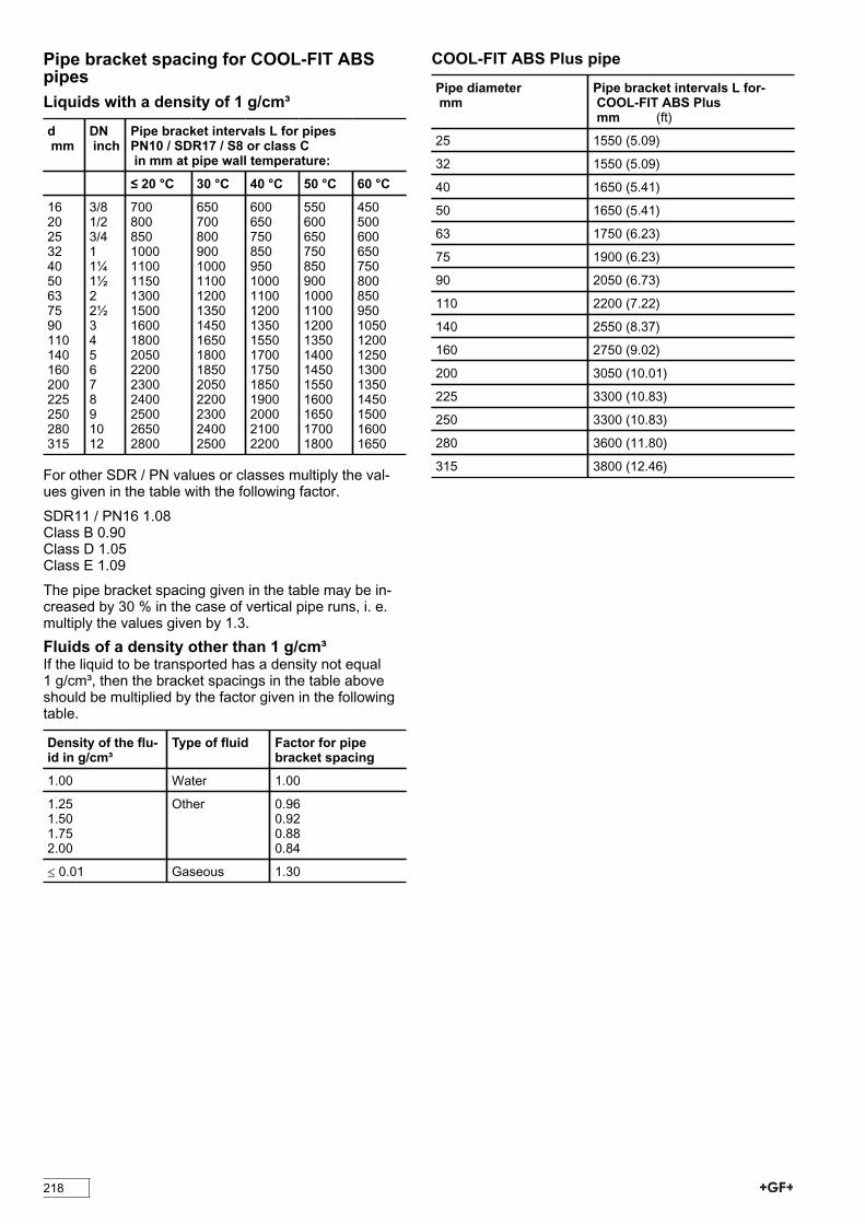
Pipe bracket spacing for COOL-FIT ABSpipesLiquids with a density of 1 g/cm³d mm
DN inch
Pipe bracket intervals L for pipes PN10 / SDR17 / S8 or class C in mm at pipe wall temperature:
≤ 20 °C 30 °C 40 °C 50 °C 60 °C
162025324050637590110140160200225250280315
3/81/23/411¼1½22½34567891012
70080085010001100115013001500160018002050220023002400250026502800
6507008009001000110012001350145016501800185020502200230024002500
600650750850950100011001200135015501700175018501900200021002200
55060065075085090010001100120013501400145015501600165017001800
450500600650750800850950105012001250130013501450150016001650
For other SDR / PN values or classes multiply the val-ues given in the table with the following factor.
SDR11 / PN16 1.08Class B 0.90Class D 1.05Class E 1.09
The pipe bracket spacing given in the table may be in-creased by 30 % in the case of vertical pipe runs, i. e.multiply the values given by 1.3.Fluids of a density other than 1 g/cm³If the liquid to be transported has a density not equal1 g/cm³, then the bracket spacings in the table aboveshould be multiplied by the factor given in the followingtable.
Density of the flu-id in g/cm³
Type of fluid Factor for pipebracket spacing
1.00 Water 1.00
1.251.501.752.00
Other 0.960.920.880.84
≤ 0.01 Gaseous 1.30
COOL-FIT ABS Plus pipePipe diameter mm
Pipe bracket intervals L for- COOL-FIT ABS Plus mm (ft)
25 1550 (5.09)
32 1550 (5.09)
40 1650 (5.41)
50 1650 (5.41)
63 1750 (6.23)
75 1900 (6.23)
90 2050 (6.73)
110 2200 (7.22)
140 2550 (8.37)
160 2750 (9.02)
200 3050 (10.01)
225 3300 (10.83)
250 3300 (10.83)
280 3600 (11.80)
315 3800 (12.46)

219
Pipe bracket spacing for PE pipesLiquids with a density of 1 g/cm³d mm
Pipe bracket intervals L for pipes SDR 11 in mm at pipe wall temperature:
≤20 °C 30 °C 40 °C 50 °C 60 °C
16 20 25 32 40 50 63 75 90
110 125 140 160 180 200 225 250 280 315 355 400 450500
500 575 650 750 900 1050 1200 13501500 1650 1750 1900 2050 2150 2300 2450 2600 2750 29003100330035503900
450550600750850100011501300145016001700185019502050220023502500265028003000315034003650
45050055065075090010501200135015001600175018501950210022502400255027002900305033003500
40045055065075085010001100125014501550165017501850200021502300240025502750290031003350
350400500550650750900
1000115013001400150016001750190020502100220023502550270029003100
For other SDR multiply the values given in the table withthe following factor:
SDR 17 and SDR 17.6 with 0.91SDR 7.4 with 1.07
The pipe bracket spacing given in the table may be in-creased by 30 % in the case of vertical pipe runs, i. e.multiply the values given by 1.3.Fluids of a density other than 1 g/cm³If the liquid to be transported has a density not equal1 g/cm³, then the bracket spacing in the table aboveshould be multiplied by the factor of the following table.
Density of the flu-id in g/cm³
Type of fluid Factor for pipebracket spacing
1.00 Water 1.00
1.251.501.752.00
Other 0.960.920.880.84
≤ 0.01 Gaseous 1.30 for SDR111.21 for SDR7.4

220
Pipe bracket spacing for PP pipesPP-H pipes with liquids with a density of 1 g/cm³d mm
Pipe bracket intervals L for SDR 11 pipes in mm at pipe wall temperature:
≤20 °C 30 °C 40 °C 50 °C 60 °C 70 °C 80 °C
16 650 625 600 575 550 525 500
20 700 675 650 625 600 575 550
25 800 775 750 725 700 675 650
32 950 925 900 875 850 800 750
40 1100 1075 1050 1000 950 925 875
50 1250 1225 1200 1150 1100 1050 1000
63 1450 1425 1400 1350 1300 1250 1200
75 1550 1500 1450 1400 1350 1300 1250
90 1650 1600 1550 1500 1450 1400 1350
110 1850 1800 1750 1700 1600 1500 1400
125 2000 1950 1900 1800 1700 1600 1500
140 2100 2050 2000 1900 1800 1700 1600
160 2250 2200 2100 2000 1900 1800 1700
180 2350 2300 2200 2100 2000 1900 1800
200 2500 2400 2300 2200 2100 2000 1900
225 2650 2550 2450 2350 2250 2150 2000
250 2800 2700 2600 2500 2400 2300 2150
315 3150 3050 2950 2850 2700 2600 2450
355 3350 3250 3150 3000 2850 2750 2600
400 3550 3450 3350 3200 3050 2900 2750
450 3800 3700 3600 3450 3300 3100 2950
500 4100 4000 3850 3700 3500 3350 3150
For other SDR multiply the values given in the table withthe following factor:
SDR17 and SDR17.6 with 0.91
The pipe bracket spacing given in the table may be in-creased by 30 % in the case of vertical pipe runs, i. e.multiply the values given by 1.3.PP-H pipes with fluids of a density other than 1g/cm³If the liquid to be transported has a density not equal1 g/cm³, then the bracket spacing in the table aboveshould be multiplied by the factor given in the followingtable.
Density of the flu-id in g/cm³
Type of fluid Factor for pipebracket spacing
1.00 Water 1.00
1.251.501.752.00
Other 0.960.920.880.84
≤ 0.01 Gaseous 1.30 for SDR111.47 for SDR17.6 andSDR17

221
PP-R pipes with liquids with a density of 1 g/cm³d mm
Pipe bracket intervals L for SDR 11 pipes in mm at pipe wall temperature:
≤20 °C 30 °C 40 °C 50 °C 60 °C 70 °C 80 °C
16 500 475 450 425 425 400 375
20 525 500 500 475 450 425 425
25 600 575 575 550 525 500 500
32 725 700 675 650 650 600 575
40 825 800 800 750 725 700 650
50 950 925 900 875 825 775 750
63 1100 1075 1050 1025 975 925 900
75 1150 1150 1100 1050 1000 975 950
90 1250 1200 1150 1150 1100 1050 1000
110 1400 1350 1300 1300 1200 1125 1050
125 1500 1450 1450 1350 1300 1200 1150
140 1600 1550 1500 1450 1350 1275 1200
160 1700 1650 1600 1500 1450 1350 1300
180 1750 1750 1650 1600 1500 1425 1350
200 1900 1800 1750 1650 1600 1500 1450
225 2000 1900 1850 1750 1700 1600 1500
250 2100 2050 1950 1900 1800 1700 1600
315 2350 2300 2200 2150 2050 1950 1850
355 2500 2425 2350 2250 2125 2050 1950
400 2650 2575 2500 2400 2275 2175 2050
450 2850 2775 2700 2575 2475 2325 2200
500 3075 3000 2875 2775 2625 2500 2350
For other SDR multiply the values given in the table withthe following factor:
SDR17 and SDR17.6 with 0.91
The pipe bracket spacing given in the table may be in-creased by 30 % in the case of vertical pipe runs, i. e.multiply the values given by 1.3.PP-R pipes with fluids of a density other than 1g/cm³If the liquid to be transported has a density not equal1 g/cm³, then the bracket spacing in the table aboveshould be multiplied by the factor given in the followingtable.
Density of the flu-id in g/cm³
Type of fluid Factor for pipebracket spacing
1.00 Water 1.00
1.251.501.752.00
Other 0.960.920.880.84
≤ 0.01 Gaseous 1.30 for SDR111.47 for SDR17.6 andSDR17

222
Pipe bracket spacing for PVC pipesPVC-U pipes with liquids with a density of 1 g/cm³d DN Pipe bracket intervals L for SDR21 / S 10 /
PN10 pipes in mm at pipe wall temperature:
mm inch ≤20 °C 30 °C 40 °C 50 °C 60 °C 16 2025 32 40 50 63 75 90 110 125 140 160 180 200 225 250 280 315 355 400
3/8 ½ ¾ 1 1¼ 1½ 2 2½3 4 -5 6 --8-1012 14 16
950 1100 1200 1350 1450 1600 1800 2000 2200 2400 2550 2700 2900 3100 3250 3450 3650 3750 4100 4300 4600
900 1050 1150 1300 1400 1550 1750 1900 2100 2300 2450 2600 2800 2950 3150 3300 3500 3700 3900 4200 4450
850 1000 1050 1250 1350 1500 1700 1850 2000 2250 2400 2500 2700 2850 3000 3200 3350 3550 3750 4000 4250
750 900 950 1100 1250 1400 1550 1700 1850 2050 2200 2300 2500 2650 2800 2950 3100 3300 3500 3700 3950
600 700 750 900 1000 11501300 1450 1550 1750 1850 1950 2100 2200 23502500 2600 2750 2950 3100 3300
For other SDR / PN multiply the values given in the ta-ble with the following factor:SDR51 / S25 / PN4 with 0.83SDR34.3 / S16.7 / PN6 with 0.90SDR13.6 / S 6.3 / PN16 with 1.08SDR11 / S 5 / PN20 with 1.15
The pipe bracket spacing given in the table may be in-creased by 30 % in the case of vertical pipe runs, i. e.multiply the values given by 1.3.PVC-U pipes with fluids of a density other than1 g/cm³If the liquid to be transported has a density not equal1 g/cm³, then the bracket spacing in the table aboveshould be multiplied by the factor given in the followingtable.
Density of the flu-id in g/cm³
Type of fluid Factor for pipebracket spacing
1.00 Water 1.00
1.251.501.752.00
Other 0.960.920.880.84
≤ 0.01 Gaseous 1.42 for SDR21 / S8 / PN101.30 for SDR13.6 / S6.3 / PN161.20 for SDR11 / S5 / PN20
223
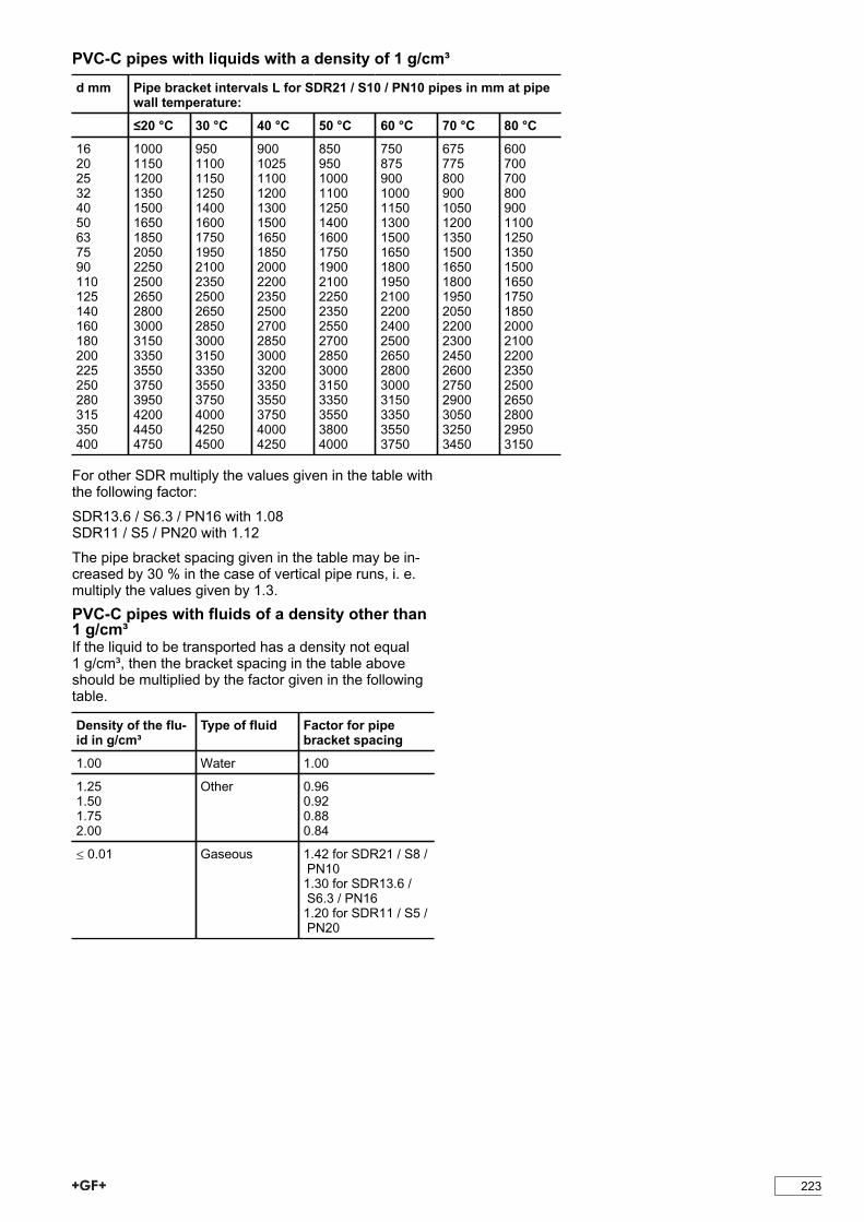
PVC-C pipes with liquids with a density of 1 g/cm³d mm Pipe bracket intervals L for SDR21 / S10 / PN10 pipes in mm at pipe
wall temperature: ≤20 °C 30 °C 40 °C 50 °C 60 °C 70 °C 80 °C
16 20 25 32 40 50 63 75 90 110 125 140 160 180 200 225 250 280 315 350 400
1000 1150 1200 1350 1500 1650 1850 2050 2250 2500 2650 2800 3000 3150 3350 3550 3750 3950 4200 4450 4750
950 1100 1150 1250 1400 1600 1750 1950 2100 2350 2500 2650 2850 3000 3150 3350 3550 3750 4000 4250 4500
900 1025 1100 1200 1300 1500 1650 1850 2000 2200 2350 2500 2700 2850 3000 3200 3350 3550 3750 4000 4250
850 950 1000 1100 1250 1400 1600 1750 1900 2100 2250 2350 2550 2700 2850 3000 3150 3350 3550 3800 4000
750 875 900 1000 1150 1300 1500 1650 1800 1950 2100 2200 2400 2500 2650 2800 3000 3150 3350 3550 3750
675 775 800 900 1050 1200 1350 1500 1650 1800 1950 2050 2200 2300 2450 2600 2750 2900 3050 3250 3450
600 700 700 800 900 1100 1250 1350 1500 1650 1750 1850 2000 2100 2200 23502500 2650 2800 2950 3150
For other SDR multiply the values given in the table withthe following factor:
SDR13.6 / S6.3 / PN16 with 1.08SDR11 / S5 / PN20 with 1.12
The pipe bracket spacing given in the table may be in-creased by 30 % in the case of vertical pipe runs, i. e.multiply the values given by 1.3.PVC-C pipes with fluids of a density other than1 g/cm³If the liquid to be transported has a density not equal1 g/cm³, then the bracket spacing in the table aboveshould be multiplied by the factor given in the followingtable.
Density of the flu-id in g/cm³
Type of fluid Factor for pipebracket spacing
1.00 Water 1.00
1.251.501.752.00
Other 0.960.920.880.84
≤ 0.01 Gaseous 1.42 for SDR21 / S8 / PN101.30 for SDR13.6 / S6.3 / PN161.20 for SDR11 / S5 / PN20

224
Pipe bracket spacing for PVDF pipesLiquids with a density of 1 g/cm³d mm
Pipe bracket spacing L for pipes PN16 / SDR21 in mm at pipe wall temperature:
≤20 °C 30 °C 40 °C 50 °C 60 °C 70 °C 80 °C 100 °C 120 °C 140 °C
16 20 25 32 40 50
725 850 950 1100 1200 1400
700 800 900 1050 1150 1350
650 750 850 1000 1100 1300
600 750 800 950 1050 1200
575700 750 9001000 1150
550650 700 850 950 1100
500 600 675 800 900 1000
450500 600 700 750 900
400450 500 600 650 750
300 400 450 500 550 600
d mm
Pipe bracket spacing L for pipes PN10 / SDR33 in mm at pipe wall temperature:
≤20 °C 30 °C 40 °C 50 °C 60 °C 70 °C 80 °C 100 °C 120 °C 140 °C
63 75 90 110 125 140 160 180 200 225 250 280 315 355 400 450
1400 1500 1600 1800 1900 2000 2150 2300 2400 2550 2650 2850 3000 3200 34003650
1350 1450 1550 1750 1850 1950 2100 2200 2350 2500 2600 2750 2950 3100 33003550
1300 1400 1500 1700 1800 1900 2050 2150 2250 2400 2500 2650 2850 3000 32003450
1250 1350 1450 1650 1700 1800 1950 2050 2150 2300 2400 2550 2750 2850 30503300
1200 1300 1400 1550 1650 1750 1850 1950 2100 2200 2300 2450 2600 2750 29503200
1150125013501500160017001800190020002100220023502500265028003000
1100120013001450150016001700180019002000210022502400250026502850
950105011001250135014501550160017001800190020002150225024002600
8008509501100120012501350140015001600170018001900200021002250
650700850950100010501150120013001400150016001650175018001900
For other PN / SDR multiply the values given in the ta-ble (diameter ≥ d63) with the following factor:PN16 / SDR33 with 1.08
Pipe bracket spacing for lines running vertically can beincreased by 30 % with respect to the values in the ta-ble, i. e. table values multiplied by 1.3.Fluids of a density other than 1 g/cm³If the liquid to be transported has a density not equal1 g/cm³, then the bracket spacing in the table aboveshould be multiplied by the factor given in the followingtable.
Density of thefluid in g/cm³
Type of fluid Factor for pipe brack-et spacing
1.00 Water 1.00
1.251.501.752.00
Other 0.960.920.880.84
≤ 0.01 Gaseous 1.48 for SDR33 / PN101.36 for SDR21 / PN16

225
Pipe bracket spacing plastics pipes in car-riers
Continuous support may be more economical andpracticable than pipe brackets for horizontal or verticalpipework, especially for small diameter pipes and in ar-eas with high temperatures.
In order to avoid inadmissible loadings on the pipeline-s ensure during assembling an overlapping of the carri-ers in the pipe brackets.
The following table indicates the spacing distanceswhen using carriers. These values apply regardless ofthe type of piping material or the temperature.
d mm
Spacing of supports when using carri-ers mm
16 20 25 32 40 50 63 75 90 110
1600 1750 1900 2000 2150 2300 2500 2600 2750 2900