
Pins & Bushings1 - i.b5z.neti.b5z.net/i/u/1126586/i/Danly PDF/PinsBushingsInch.pdf · are designed...
44
PINS & BUSHINGS – INCH PINS & BUSHINGS – INCH PINS & BUSHINGS – INCH TRUSTED SOLUTIONS AND INNOVATION Steel, Bronze & Self-Lubricating Friction & Ball Bearing Components
Transcript of Pins & Bushings1 - i.b5z.neti.b5z.net/i/u/1126586/i/Danly PDF/PinsBushingsInch.pdf · are designed...

www.danly.com
PINS & BUSHINGS – INCHPINS & BUSHINGS – INCHPINS & BUSHINGS – INCH
TRUSTED SOLUTIONS AND INNOVATION
Steel, Bronze &Self-Lubricating
Friction & BallBearing Components

www.danly.com PINS & BUSHINGS – INCH
Strategically located to serve you betterDanly IEM, a division of Connell Limited Partnership, is a global leader in die sets and diecomponent products. Our vast product line includes many well known brand names such asDanly Die Set®, IEM® and Punchrite®. Known for high quality and exceptional service, theDanly IEM products are readily available through our global network of distributors and directsales personnel. With the global reach of Danly IEM, feel confident that wherever your dies arebuilt or running, you can rely on Danly IEM for all your die component needs. Put the Danly IEMnetwork to work for you. Call us today. We’ve got the service you’ve been looking for.
Included in our full line offering are both inch and metric size die sets and die components thatare designed to numerous die standards including ISO, NAAMS, JIS and many large automotiveand appliance manufacturers' standards. The complete product offering includes:
• Ball bearing and friction style die sets including custom and catalog sets• Machined plate• Guide posts & bushings• ISO and JIS Die springs• In-die tapping units for both mechanical and hydraulic presses• FormathaneTM Urethane springs, strippers, sheets, bars, rods and die cover film• Diemakers’ supplies such as pry bars, hoist rings, clamps and fasteners• Standard and self-lubricating wear product including wear plate, wear strips, gibs,
keeper plates and guide blocks• Cam units, including Milfab®, MiniTM, Aerial and Die Mount styles• AccubendTM Rotary Benders• Standard and Ball lock punches and retainers• Coil Safe• Air presses• Spool type pad retainers• Nitrogen gas springs
®
Our facility has been Registered by Underwriters Laboratories, Inc.to the International Organization for Standardization ISO 9000Series Standards for Quality."Registered by UL to ISO 9001."
®
ISO 9001: 2000A6707A3044

i
www.danly.comPINS & BUSHINGS CONTENTS
General Information ii
Plain Bearing Guide PostsPress Fit Commercial & Precision Guide Posts 2Demountable Commercial & Precision Guide Posts 4Removable Precision Guide Posts 6Oversize Shoulder Press Fit Guide Posts 7
Plain Bearing BushingsDemountable Bronze, Bronze-Plated & Steel Bushings
(Extra Long, Standard and Short Shoulder Series) 8Demountable Self-Lubricating Bushings 10Demountable Low Profile Bronze-Plated Bushings 12Oversize Shoulder Demountable Bushings 13Press Fit Bushings 14Press Fit Self-Lubricating Straight Bushings 15Press Fit Self-Lubricating Shoulder Bushings 16Demountable Bosses 17
Ball Bearing ComponentsBall Bearing Cages 18Ball Bearing Press Fit Guide Posts 19Ball Bearing Demountable Guide Posts 20Ball Bearing Demountable Bushings 22Ball Bearing Straight Sleeve Bushings 23
Mold ComponentsMold Components - Guide Posts 24Mold Components - Self-Lubricating Ejector Bushings 26
Selection GuidesBall Bearing Components Selection Guide 27Type I Component Selection Guide 28Type II & III Component Selection Guide 30Type II & III Bushing & Ball Cage Selection Guide 32
Technical InformationBall Bearing Components Technical Information 34Plain Bearing Components Technical Information 35Clamp Dimensions for Demountable Posts and Bushings 36
PAGE NUMBER

ii
www.danly.com
As the premier die set manufacturer, we offer a complete line of catalog die sets as wellas custom complex and simple sets. For replacement parts and for those customers wanting toassemble their own sets, an extensive line of catalog guide posts and bushings in both plainbearing and ball bearing styles is available for immediate delivery.
Our plain bearing guide posts are available in press fit, demountable and removablestyles. The press fit and demountable styles are available in commercial and precision series.Precision guide posts are hardened, ground and hard chrome plated to provide an exceptionallysmooth, hard wearing surface as well as providing resistance to corrosion, less friction andmaintenance of close working fits.
Our plain bearing bushings are available in press fit and demountable styles and areequipped with figure 8 oil grooves and lubrication fittings. Our demountable bushings areavailable in three profiles, standard, short and extra long shoulder to give optimum flexibility indie set design. The bushings are also available in steel, bronze, bronze-plated and self-lubricatingmaterials and are ideally suited for running with commercial and precision posts. All demountablebushings are pre-fitted to the same diameter guide posts to ensure that the bushings and guideposts of the same diameter are completely interchangeable.
Demountable posts and bushings are tap fit into location and seat flush with the groundface of the punch holder or die shoe. They are held in place with toe clamps and screws whichprovide perfect alignment of the post and bushing with the bore perpendicular to the groundsurface of the punch holder or shoe. The clamp and screws provide four times the holdingpower compared to pressed-in components, yet they can be easily removed and assembledthus simplifying die building and maintenance.
The ball bearing system includes press fit and demountable guide posts, press fit sleeveand demountable bushings as well as ball cages. The ball bearing guide posts are manufacturedfrom hardened steel to assure free rolling of balls and high wear resistance. Each post is drilledand tapped at the bottom for mounting of the ball cage washer assembly. This unique mountingmethod permits the ball cage, except when under pre-load, to freely rotate 360 degrees aroundthe guide post thus eliminating scoring or tracking of the guide post surface. The ball bearingsare arranged in the cage in a spiral pattern which also minimizes tracking or grooving andassures uniform wear.
General Information

1
General Information
Our demountable bushings and guide postsprovide ease of assembly.
Demountable bushings are secured to thepunch holder with our clamps and screws,proving four times the holding power ofpressed-in bushings.
Special equipment spins ball bearings inplace, then our ball cages move on to rigidquality inspection.
Unlike others, the ball bearings in our cagesare spun a full 360° into place for maximumprotection from accidental ball dislodgement.
Specially-designed spiral patterns are drilledinto our ball cages to control tracking andgrooving.
OURS OTHERS

2
Press FitCommercial and Precision Guide Posts
Press fit guide posts are available in commercial and precisionseries. Both series are manufactured from high quality hardened steeland finish ground for a high precision finish and ideally suited forrunning with steel, bronze or self-lubricating bushings. The precisionseries has a hard chrome finish providing an exceptionally smooth,hard wearing surface thus reducing friction between the post andbearing. Utilizing the precision microme guide posts will greatlyimprove the accuracy and working life of die sets as well as provideadditional corrosion resistance.
Product Features
NOTES:
♦ See page 35 for die setboring specifications.
DIMENSIONS:
*C = 1" for 5-0414-1,5-0614-1 & 5-0614-5
**C = 1 ¾" for part numberswhere L is less than orequal to 7", C=2" for partnumbers where L=7 ½"or greater
5-0820-5
Diameter Length Precision Commercial A (in) L (in) Part Number Part Number
1/2 3 1/2 5-0414-1 — 1/2 4 5-0416-1 — 1/2 4 1/4 5-0417-1 — 1/2 4 1/2 5-0418-1 — 1/2 4 3/4 5-0419-1 — 1/2 5 5-0420-1 — 1/2 5 1/4 5-0421-1 — 1/2 5 1/2 5-0422-1 — 5/8 4 5-0516-1 — 5/8 4 1/4 5-0517-1 — 5/8 4 1/2 5-0518-1 — 5/8 4 3/4 5-0519-1 — 5/8 5 5-0520-1 — 5/8 5 1/2 5-0522-1 — 5/8 6 5-0524-1 — 3/4 3 1/2 5-0614-1 5-0614-5 3/4 4 5-0616-1 5-0616-5 3/4 4 1/4 5-0617-1 5-0617-5 3/4 4 1/2 5-0618-1 5-0618-5 3/4 4 3/4 5-0619-1 5-0619-5 3/4 5 5-0620-1 5-0620-5 3/4 5 1/2 5-0622-1 5-0622-5 3/4 6 5-0624-1 5-0624-5 3/4 7 — 5-0628-5 3/4 8 — 5-0632-5 7/8 4 5-0716-1 5-0716-5 7/8 4 1/4 5-0717-1 5-0717-5 7/8 4 1/2 5-0718-1 5-0718-5 7/8 4 3/4 5-0719-1 5-0719-5 7/8 5 5-0720-1 5-0720-5 7/8 5 1/4 5-0721-1 5-0721-5 7/8 5 1/2 5-0722-1 5-0722-5 7/8 5 3/4 5-0723-1 5-0723-5 7/8 6 5-0724-1 5-0724-5 7/8 6 1/2 5-0726-1 5-0726-5 7/8 7 5-0728-1 5-0728-5 7/8 7 1/2 5-0730-1 5-0730-5 7/8 8 5-0732-1 5-0732-5
1/2
3/4
5/8
7/8
Press Fit Dimensions Press fit Press fit
Diameter A Diameter D Length C(in) (in) (in)1/2 0.5017 1 1/8* 5/8 0.6267 1 1/83/4 0.752 1 1/8*7/8 0.877 1 1/41 1.002 1 1/2
1 1/4 1.2525 1 3/41 1/2 1.5025 1 3/4 - 2**1 3/4 1.7525 2 1/4
2 2.0025 2 1/22 1/2 2.503 3 1/2
3 3.003 3 1/2

3
Diameter Length Precision Commercial A (in) L (in) Part Number Part Number
Press FitCommercial and Precision Guide Posts
1 3/4 6 5-1424-1 5-1424-51 3/4 6 1/2 5-1426-1 5-1426-51 3/4 7 5-1428-1 5-1428-51 3/4 7 1/2 5-1430-1 5-1430-51 3/4 8 5-1432-1 5-1432-51 3/4 8 1/2 5-1434-1 5-1434-51 3/4 9 5-1436-1 5-1436-51 3/4 10 5-1440-1 5-1440-51 3/4 11 5-1444-1 5-1444-51 3/4 12 5-1448-1 5-1448-51 3/4 14 5-1456-1 5-1456-5
2 6 5-1624-1 5-1624-52 6 1/2 5-1626-1 5-1626-52 7 5-1628-1 5-1628-52 7 1/2 5-1630-1 5-1630-52 8 5-1632-1 5-1632-52 8 1/2 5-1634-1 5-1634-52 9 5-1636-1 5-1636-52 10 5-1640-1 5-1640-52 11 5-1644-1 5-1644-52 12 5-1648-1 5-1648-52 13 5-1652-1 5-1652-52 14 5-1656-1 5-1656-52 17 5-1668-1 5-1668-52 20 5-1680-1 5-1680-5
2 1/2 8 5-2032-1 5-2032-52 1/2 8 1/2 5-2034-1 5-2034-52 1/2 9 5-2036-1 5-2036-52 1/2 10 5-2040-1 5-2040-52 1/2 11 5-2044-1 5-2044-52 1/2 12 5-2048-1 5-2048-52 1/2 13 5-2052-1 5-2052-52 1/2 14 5-2056-1 5-2056-52 1/2 17 5-2068-1 5-2068-52 1/2 20 5-2080-1 5-2080-5
3 8 5-2432-1 5-2432-53 8 1/2 5-2434-1 5-2434-53 9 5-2436-1 5-2436-53 10 5-2440-1 5-2440-53 11 5-2444-1 5-2444-53 12 5-2448-1 5-2448-53 13 5-2452-1 5-2452-53 14 5-2456-1 5-2456-53 17 5-2468-1 5-2468-53 20 5-2480-1 5-2480-5
Diameter Length Precision Commercial A (in) L (in) Part Number Part Number
1 3/4
2 1/2
3
2
1 4 5-0816-1 5-0816-51 4 1/4 5-0817-1 5-0817-51 4 1/2 5-0818-1 5-0818-51 4 3/4 5-0819-1 5-0819-51 5 5-0820-1 5-0820-51 5 1/4 5-0821-1 5-0821-51 5 1/2 5-0822-1 5-0822-51 5 3/4 5-0823-1 5-0823-51 6 5-0824-1 5-0824-51 6 1/2 5-0826-1 5-0826-51 7 5-0828-1 5-0828-51 7 1/2 5-0830-1 5-0830-51 8 5-0832-1 5-0832-51 8 1/2 5-0834-1 5-0834-51 9 5-0836-1 5-0836-51 10 5-0840-1 5-0840-51 11 5-0844-1 5-0844-51 12 5-0848-1 5-0848-5
1 1/4 4 1/2 5-1018-1 5-1018-51 1/4 4 3/4 5-1019-1 5-1019-51 1/4 5 5-1020-1 5-1020-51 1/4 5 1/4 5-1021-1 5-1021-51 1/4 5 1/2 5-1022-1 5-1022-51 1/4 5 3/4 5-1023-1 5-1023-51 1/4 6 5-1024-1 5-1024-51 1/4 6 1/2 5-1026-1 5-1026-51 1/4 7 5-1028-1 5-1028-51 1/4 7 1/2 5-1030-1 5-1030-51 1/4 8 5-1032-1 5-1032-51 1/4 8 1/2 5-1034-1 5-1034-51 1/4 9 5-1036-1 5-1036-51 1/4 10 5-1040-1 5-1040-51 1/4 11 5-1044-1 5-1044-51 1/4 12 5-1048-1 5-1048-51 1/2 4 1/2 5-1218-1 5-1218-51 1/2 4 3/4 5-1219-1 5-1219-51 1/2 5 5-1220-1 5-1220-51 1/2 5 1/4 5-1221-1 5-1221-51 1/2 5 1/2 5-1222-1 5-1222-51 1/2 5 3/4 5-1223-1 5-1223-51 1/2 6 5-1224-1 5-1224-51 1/2 6 1/2 5-1226-1 5-1226-51 1/2 7 5-1228-1 5-1228-51 1/2 7 1/2 5-1230-1 5-1230-51 1/2 8 5-1232-1 5-1232-51 1/2 8 1/2 5-1234-1 5-1234-51 1/2 9 5-1236-1 5-1236-51 1/2 10 5-1240-1 5-1240-51 1/2 11 5-1244-1 5-1244-51 1/2 12 5-1248-1 5-1248-51 1/2 13 — 5-1252-51 1/2 14 — 5-1256-51 1/2 15 — 5-1260-5
1
1 1/2
1 1/4

4
Demountable Commercialand Precision Guide Posts
5-0820-6
Press fit guide posts are available in commercial and precisionseries. Both series are manufactured from high quality hardenedsteel and finish ground for a high precision finish and ideally suitedfor running with steel, bronze or self-lubricating bushings. Theprecision series have a hard chrome finish providing an exceptionallysmooth, hard wearing surface thus reducing friction between the postand bearing. Utilizing the precision microme guide posts will greatlyimprove the accuracy and working life of die sets as well as provideadditional corrosion resistance.
Demountable posts are tap fit and held in place with toe clampsand screws. They can be removed and assembled multiple timeswithout damaging or distorting the mounting holes in the die set thussimplifying die building and maintenance. Demountable posts arealso used to replace press fit posts when the press fit hole has beendamaged and the straight pin no longer fits securely in the hole.
Product Features
NOTES:
♦ All demountable guide posts aresupplied with mounting clampsand screws. See pages 36 & 37for clamping dimensions or toorder additional toe clamps ormounting screws.
♦ Length of post must be specifiedfrom shoulder, not overall length.Add thickness of die holder toF dimension to find L dimensionof assembled set.
♦ Dimension X is the minimumdistance between inside surfaceof shoe and holder with bushingshoulder resting on screw head.The dimension varies with shoulderand short shoulder bushings.
Post Shoulder Shoulder Press Fit Minimum Shut Height X (in)Diameter A Diameter B Length D Length E Bushing Style
(in) (in) (in) (in) Shoulder Short Shoulder 7/8 1 3/16 0.193 15/16 2 23/64 1 27/64
1 1 5/16 0.193 1 3/16 2 23/64 1 27/641 1/4 1 9/16 0.250 1 3/16 2 3/4 1 9/161 1/2 1 7/8 0.250 1 9/16 2 3/4 1 9/161 3/4 2 1/4 0.250 1 11/16 2 3/4 1 3/4
2 2 1/2 0.250 1 15/16 2 3/4 1 3/42 1/2 3 1/32 0.250 1 15/16 3 1/4 1 3/4
3 3 1/2 0.250 2 7/16 3 1/4 1 3/4

5
Demountable Commercialand Precision Guide Posts
Working Diameter A Length F Precision Commercial
(in) (in) Part Number Part Number7/8 2 3/4 5-0711-6 5-0711-77/8 3 5-0712-6 5-0712-77/8 3 1/4 5-0713-6 5-0713-77/8 3 1/2 5-0714-6 5-0714-77/8 3 3/4 5-0715-6 5-0715-77/8 4 5-0716-6 5-0716-77/8 4 1/4 5-0717-6 5-0717-77/8 4 1/2 5-0718-6 5-0718-77/8 4 3/4 5-0719-6 5-0719-77/8 5 1/4 5-0721-6 5-0721-77/8 5 3/4 5-0723-6 5-0723-77/8 6 1/4 5-0725-6 5-0725-77/8 6 3/4 5-0727-6 5-0727-71 2 1/2 5-0810-6 5-0810-71 2 3/4 5-0811-6 5-0811-71 3 5-0812-6 5-0812-71 3 1/4 5-0813-6 5-0813-71 3 1/2 5-0814-6 5-0814-71 3 3/4 5-0815-6 5-0815-71 4 5-0816-6 5-0816-71 4 1/4 5-0817-6 5-0817-71 4 1/2 5-0818-6 5-0818-71 5 5-0820-6 5-0820-71 5 1/2 5-0822-6 5-0822-71 6 5-0824-6 5-0824-71 6 1/2 5-0826-6 5-0826-71 7 5-0828-6 5-0828-71 7 1/2 5-0830-6 5-0830-7
1 1/4 2 3/4 5-1011-6 5-1011-71 1/4 3 5-1012-6 5-1012-71 1/4 3 1/4 5-1013-6 5-1013-71 1/4 3 1/2 5-1014-6 5-1014-71 1/4 3 3/4 5-1015-6 5-1015-71 1/4 4 5-1016-6 5-1016-71 1/4 4 1/4 5-1017-6 5-1017-71 1/4 4 3/4 5-1019-6 5-1019-71 1/4 5 1/4 5-1021-6 5-1021-71 1/4 5 3/4 5-1023-6 5-1023-71 1/4 6 1/4 5-1025-6 5-1025-71 1/4 6 3/4 5-1027-6 5-1027-71 1/4 7 1/4 5-1029-6 5-1029-71 1/4 8 1/4 5-1033-6 5-1033-71 1/4 9 1/4 5-1037-6 5-1037-71 1/4 10 1/4 5-1041-6 5-1041-71 1/2 2 3/4 5-1211-6 5-1211-71 1/2 3 5-1212-6 5-1212-71 1/2 3 1/4 5-1213-6 5-1213-71 1/2 3 1/2 5-1214-6 5-1214-71 1/2 3 3/4 5-1215-6 5-1215-71 1/2 4 5-1216-6 5-1216-71 1/2 4 1/4 5-1217-6 5-1217-71 1/2 4 3/4 5-1219-6 5-1219-7
1
1 1/2
7/8
1 1/4
1 1/2 5 1/4 5-1221-6 5-1221-71 1/2 5 3/4 5-1223-6 5-1223-71 1/2 6 1/4 5-1225-6 5-1225-71 1/2 6 3/4 5-1227-6 5-1227-71 1/2 7 1/4 5-1229-6 5-1229-71 1/2 8 1/4 5-1233-6 5-1233-71 1/2 9 1/4 5-1237-6 5-1237-71 1/2 10 1/4 5-1241-6 5-1241-71 3/4 3 1/2 5-1414-6 5-1414-71 3/4 4 5-1416-6 5-1416-71 3/4 4 1/2 5-1418-6 5-1418-71 3/4 5 5-1420-6 5-1420-71 3/4 5 1/2 5-1422-6 5-1422-71 3/4 6 5-1424-6 5-1424-71 3/4 6 1/2 5-1426-6 5-1426-71 3/4 7 1/2 5-1430-6 5-1430-71 3/4 8 1/2 5-1434-6 5-1434-71 3/4 9 1/2 5-1438-6 5-1438-71 3/4 11 1/2 5-1446-6 5-1446-7
2 3 1/2 5-1614-6 5-1614-72 4 5-1616-6 5-1616-72 4 1/2 5-1618-6 5-1618-72 5 5-1620-6 5-1620-72 5 1/2 5-1622-6 5-1622-72 6 5-1624-6 5-1624-72 6 1/2 5-1626-6 5-1626-72 7 1/2 5-1630-6 5-1630-72 8 1/2 5-1634-6 5-1634-72 9 1/2 5-1638-6 5-1638-72 10 1/2 5-1642-6 5-1642-72 11 1/2 5-1646-6 5-1646-72 14 1/2 5-1658-6 5-1658-72 17 1/2 5-1670-6 5-1670-7
2 1/2 4 1/2 5-2018-6 5-2018-72 1/2 5 5-2020-6 5-2020-72 1/2 5 1/2 5-2022-6 5-2022-72 1/2 6 1/2 5-2026-6 5-2026-72 1/2 7 1/2 5-2030-6 5-2030-72 1/2 8 1/2 5-2034-6 5-2034-72 1/2 9 1/2 5-2038-6 5-2038-72 1/2 10 1/2 5-2042-6 5-2042-72 1/2 13 1/2 5-2054-6 5-2054-72 1/2 16 1/2 5-2066-6 5-2066-7
3 4 1/2 5-2418-6 5-2418-73 5 5-2420-6 5-2420-73 5 1/2 5-2422-6 5-2422-73 6 1/2 5-2426-6 5-2426-73 7 1/2 5-2430-6 5-2430-73 8 1/2 5-2434-6 5-2434-73 9 1/2 5-2438-6 5-2438-73 10 1/2 5-2442-6 5-2442-73 13 1/2 5-2454-6 5-2454-73 16 1/2 5-2466-6 5-2466-7
Working Diameter A Length F Precision Commercial
(in) (in) Part Number Part Number
3
2
1 3/4
2 1/2
1 1/2

6
Removable PrecisionGuide Posts
5-0820-4
Removable guide posts are easily assembled and disassembledand are designed for use in applications where it is desirable tosharpen the die while still mounted in the die set. The posts areinstalled into the die set and locked into place with a steel taper lockpin. The lock pin can be driven out for easy post removal. Removableposts have a microme finish and are ideally suited for running withsteel, bronze or self-lubricating bushings. They are manufactured fromhigh quality hardened steel and finish ground for a high precisionfinish. The hard chrome finish provides an exceptionally smooth,hard wearing surface thus reducing friction between the post andbearing. Utilizing the microme guide posts will greatly improve theaccuracy and working life of die sets as well as provide additionalcorrosion resistance.
Product Features
NOTES:
♦ All removable guide posts areshipped with taper pin.
PostDiameter A Length L Precision
(in) (in) Part Number
1 3/4 6 1/2 5-1426-4
1 3/4 7 5-1428-41 3/4 7 1/2 5-1430-4
1 3/4 8 5-1432-4
1 3/4 8 1/2 5-1434-4
1 3/4 9 5-1436-4
1 3/4 10 5-1440-4
1 3/4 11 5-1444-4
1 3/4 12 5-1448-4
1 3/4 14 5-1456-4
2 6 5-1624-4
2 6 1/2 5-1626-4
2 7 5-1628-4
2 7 1/2 5-1630-42 8 5-1632-4
2 8 1/2 5-1634-4
2 9 5-1636-4
2 10 5-1640-4
2 11 5-1644-4
2 12 5-1648-4
2 13 5-1652-4
2 14 5-1656-4
2 17 5-1668-4
2 20 5-1680-4
1 3/4
2
PostDiameter A Length L Precision
(in) (in) Part Number
1 1/4 7 1/2 5-1030-4
1 1/4 8 5-1032-4
1 1/4 8 1/2 5-1034-4
1 1/4 9 5-1036-4
1 1/4 10 5-1040-4
1 1/4 11 5-1044-4
1 1/4 12 5-1048-41 1/2 4 1/2 5-1218-4
1 1/2 4 3/4 5-1219-4
1 1/2 5 5-1220-4
1 1/2 5 1/4 5-1221-4
1 1/2 5 1/2 5-1222-4
1 1/2 5 3/4 5-1223-4
1 1/2 6 5-1224-4
1 1/2 6 1/2 5-1226-4
1 1/2 7 5-1228-4
1 1/2 7 1/2 5-1230-4
1 1/2 8 5-1232-4
1 1/2 8 1/2 5-1234-41 1/2 9 5-1236-4
1 1/2 10 5-1240-4
1 1/2 11 5-1244-4
1 1/2 12 5-1248-4
1 3/4 6 5-1424-4
1 1/4
1 1/2
PostDiameter A Length L Precision
(in) (in) Part Number
1 4 5-0816-4
1 4 1/4 5-0817-4
1 4 1/2 5-0818-4
1 4 3/4 5-0819-4
1 5 5-0820-4
1 5 1/4 5-0821-4
1 5 1/2 5-0822-41 5 3/4 5-0823-4
1 6 5-0824-4
1 6 1/2 5-0826-4
1 7 5-0828-4
1 7 1/2 5-0830-4
1 8 5-0832-4
1 8 1/2 5-0834-4
1 9 5-0836-4
1 1/4 4 1/2 5-1018-4
1 1/4 4 3/4 5-1019-4
1 1/4 5 5-1020-4
1 1/4 5 1/4 5-1021-41 1/4 5 1/2 5-1022-4
1 1/4 5 3/4 5-1023-4
1 1/4 6 5-1024-4
1 1/4 6 1/2 5-1026-4
1 1/4 7 5-1028-4
1 1/4
1

7
Oversize Shoulder Press FitGuide Posts
These oversize shoulder guide posts are manufactured from highquality hardened steel and often used with oversize shoulder bushingsshown on page 13. The press fit diameters of these posts are thesame as the press fit of the outside diameters of the oversize shoulderbushings, thus the same hole may be bored through the punch anddie holder. The press fit diameters are 0.0075" oversize to allowgrinding stock to fit the bored hole.
Product Features
5-0820-3
Post Press Fit Press Fit Working Overall Commercial Diameter A Diameter B Length C Length D Length L Part (in) (in) (in) (in) (in) Number
1 1 1/2 1 1/2 3 4 1/2 5-0818-31 1 1/2 1 1/2 3 1/2 5 5-0820-31 1 1/2 1 1/2 4 5 1/2 5-0822-31 1 1/2 1 1/2 4 1/2 6 5-0824-31 1 1/2 1 1/2 5 6 1/2 5-0826-31 1 1/2 1 1/2 5 1/2 7 5-0828-31 1 1/2 1 1/2 6 7 1/2 5-0830-31 1 1/2 1 1/2 6 1/2 8 5-0832-3
1 1/4 1 3/4 2 3 5 5-1020-31 1/4 1 3/4 2 3 1/2 5 1/2 5-1022-31 1/4 1 3/4 2 4 6 5-1024-31 1/4 1 3/4 2 4 1/2 6 1/2 5-1026-31 1/4 1 3/4 2 5 7 5-1028-31 1/4 1 3/4 2 5 1/2 7 1/2 5-1030-31 1/4 1 3/4 2 6 8 5-1032-31 1/4 1 3/4 2 6 1/2 8 1/2 5-1034-31 1/4 1 3/4 2 7 9 5-1036-31 1/2 2 2 3/8 4 5/8 7 5-1228-31 1/2 2 2 3/8 5 1/8 7 1/2 5-1230-31 1/2 2 2 3/8 5 5/8 8 5-1232-31 1/2 2 2 3/8 6 1/8 8 1/2 5-1234-31 1/2 2 2 3/8 6 5/8 9 5-1236-31 1/2 2 2 3/8 7 1/8 9 1/2 5-1238-31 1/2 2 2 3/8 7 5/8 10 5-1240-31 3/4 2 1/4 2 7/8 4 5/8 7 1/2 5-1430-31 3/4 2 1/4 2 7/8 5 1/8 8 5-1432-31 3/4 2 1/4 2 7/8 5 5/8 8 1/2 5-1434-31 3/4 2 1/4 2 7/8 6 1/8 9 5-1436-31 3/4 2 1/4 2 7/8 6 5/8 9 1/2 5-1438-31 3/4 2 1/4 2 7/8 7 1/8 10 5-1440-3
2 2 1/2 3 3/8 4 5/8 8 5-1632-32 2 1/2 3 3/8 5 5/8 9 5-1636-32 2 1/2 3 3/8 6 5/8 10 5-1640-32 2 1/2 3 3/8 7 5/8 11 5-1644-32 2 1/2 3 3/8 8 5/8 12 5-1648-32 2 1/2 3 3/8 9 5/8 13 5-1652-3
2 1/2 3 1/4 3 7/8 5 1/8 9 5-2036-32 1/2 3 1/4 3 7/8 6 1/8 10 5-2040-32 1/2 3 1/4 3 7/8 7 1/8 11 5-2044-32 1/2 3 1/4 3 7/8 8 1/8 12 5-2048-32 1/2 3 1/4 3 7/8 9 1/8 13 5-2052-32 1/2 3 1/4 3 7/8 10 1/8 14 5-2056-3
2 1/2 3 1/4 3 7/8
2 2 1/2 3 3/8
1 3/4 2 1/4 2 7/8
1 1/2 2 2 3/8
1 1/4 1 3/4 2
1 1 1/2 1 1/2

8
Demountable BushingsBronze, Bronze-Plated & Steel
These demountable bushings are available in three profiles:standard, short and extra long shoulder to give optimum flexibility indie set design. The bushings are also available in steel, bronze andbronze-plated materials and are ideally suited for running withcommercial and precision posts. All demountable bushings areprefitted to the same diameter guide posts to ensure that the bushingsand guide posts of the same diameter are completely interchangeable.
Demountable bushings are tap fit into location and seat flush withthe ground face of the punch holder. The bushings are held in placewith toe clamps and screws which provide perfect alignment of thebushing with the bore perpendicular to the ground surface of the punchholder. The clamp and screws provide four times the holding powercompared to pressed-in bushings, yet they can be easily removedand assembled thus simplifying die building and maintenance.
All bushings are equipped with figure 8 oil grooves and lubricationfittings.
The bronze and bronze-plated demountable bushings offer superiorresistance to seizure, the major cause of bushing wear. They arerecommended in high speed applications and in applications withhide side thrust loads.
Product Features
NOTES:
♦ All demountable bushings are supplied with mountingclamps and screws. See pages 36 & 37 for clampingdimensions or to order additional toe clamps ormounting screws.
6-08-28 & 6-08-56
Post Bushing Diameters Press Fit Shoulder Overall Steel BronzeDiameter Length E Length F Length L Part Plated Part
A (in) B (in) C (in) C1(in) (in) (in) (in) Number Number1 1 1/2 1.720 1.845 15/16 3 3 15/16 6-08-56 6-08-28
1 1/4 1 3/4 1.940 2.095 1 1/8 3 4 1/8 6-10-56 6-10-281 1/2 2 2.190 2.345 1 3/16 3 4 3/16 6-12-56 6-12-281 3/4 2 1/4 2.503 2.658 1 3/8 3 4 3/8 6-14-56 6-14-28
2 2 1/2 2.909 3.064 1 5/8 3 4 5/8 6-16-56 6-16-282 1/2 3 1/4 3.659 3.814 1 7/8 3 4 7/8 6-20-56 6-20-28
3 3 3/4 4.190 4.283 1 7/8 3 4 7/8 6-24-56 6-24-28EXTR
A L
ON
G S
HO
ULD
ER

9
Demountable BushingsBronze, Bronze-Plated & Steel
6-08-64 & 6-08-48
6-08-23 & 6-08-63
Post Bushing Diameters Press Fit Shoulder Overall Steel Bronze BronzeDiameter Length E Length F Length L Part Plated Part Part
A (in) B (in) C (in) C1(in) (in) (in) (in) Number Number Number3/4 1 1/8 1.175 1.300 11/16 1 3/4 2 7/16 6-06-64 — —7/8 1 3/8 1.422 1.547 11/16 1 3/4 2 7/16 6-07-64 — —1 1 1/2 1.720 1.845 15/16 1 3/4 2 11/16 6-08-64 6-08-24 6-08-48
1 1/4 1 3/4 1.940 2.095 1 1/8 2 3 1/8 6-10-64 6-10-24 6-10-481 1/2 2 2.190 2.345 1 3/16 2 3 3/16 6-12-64 6-12-24 6-12-481 3/4 2 1/4 2.503 2.658 1 3/8 2 3 3/8 6-14-64 6-14-24 6-14-48
2 2 1/2 2.909 3.064 1 5/8 2 3 5/8 6-16-64 6-16-24 6-16-482 1/2 3 1/4 3.659 3.814 1 7/8 2 1/2 4 3/8 6-20-64 6-20-24 6-20-48
3 3 3/4 4.190 4.283 1 7/8 2 1/2 4 3/8 6-24-64 6-24-24 6-24-48
STA
ND
AR
D S
HO
ULD
ER
Post Bushing Diameters Press Fit Shoulder Overall Steel BronzeDiameter Length E Length F Length L Part Plated Part
A (in) B (in) C (in) C1(in) (in) (in) (in) Number Number3/4 1 1/8 1.175 1.300 11/16 3/4 1 7/16 6-06-63 —7/8 1 3/8 1.422 1.547 11/16 3/4 1 7/16 6-07-63 —1 1 1/2 1.720 1.845 15/16 13/16 1 3/4 6-08-63 6-08-23
1 1/4 1 3/4 1.940 2.095 1 1/8 13/16 1 15/16 6-10-63 6-10-231 1/2 2 2.190 2.345 1 3/16 13/16 2 6-12-63 6-12-231 3/4 2 1/4 2.503 2.658 1 3/8 1 2 3/8 6-14-63 6-14-23
2 2 1/2 2.909 3.064 1 5/8 1 2 5/8 6-16-63 6-16-232 1/2 3 1/4 3.659 3.814 1 7/8 1 2 7/8 6-20-63 6-20-23
3 3 3/4 4.190 4.283 1 7/8 1 2 7/8 6-24-63 6-24-23
SHO
RT
SHO
ULD
ER

10
GS100-15G
Demountable Self-LubricatingBushings
These demountable self-lubricating bushings are available instandard and short profiles and are ideally suited for running withcommercial and precision posts. They are manufactured from castaluminum bronze material and are prefitted to the same diameterguide posts to ensure that the bushings and guide posts of the samediameter are interchangeable.
Self-lubricating bushings contain graphite plugs which areimpregnated with oil. When the bushings reach 80-90°F as a resultof friction between the bushing and guide post, oil is drawn from theplug thus lubricating the wear surface. A dark smear pattern is createdon the wear surface as the oil and graphite are imbedded into thebronze or steel grain. This provides the lubrication necessary forcontinuous performance of the tool.
Demountable bushings are tap fit into location and seat flush withthe ground face of the punch holder. The bushings are held in placewith toe clamps and screws which provide perfect alignment of thebushing with the bore perpendicular to the ground surface of thepunch holder. The clamp and screws provide four times the holdingpower compared to pressed-in bushings, yet they can be easilyremoved and assembled thus simplifying die building and maintenance.
Product Features
Post Bushing Diameters Press Fit Shoulder Overall Self-LubricatingDiameter Length E Length F Length L Part
A (in) B (in) C (in) C1 (in) (in) (in) (in) Number1 1 1/2 1 9/16 1 3/4 1 3/8 1/2 1 7/8 GS100-15G1 1 1/2 1 9/16 1 3/4 2 3/8 1/2 2 7/8 GS100-23G
1 1/4 1 3/4 1 15/16 2 1/8 1 7/8 1/2 2 3/8 GS125-19G1 1/4 1 3/4 1 15/16 2 1/8 2 7/8 1/2 3 3/8 GS125-27G1 1/2 2 1 3/16 2 3/8 1 7/8 1/2 2 3/8 GS150-19G1 1/2 2 1 3/16 2 3/8 2 7/8 1/2 3 3/8 GS150-27G1 3/4 2 1/4 2 7/16 2 5/8 2 3/8 1/2 2 7/8 GS175-23G1 3/4 2 1/4 2 7/16 2 5/8 3 3/8 1/2 3 7/8 GS175-31G
2 2 1/2 2 3/4 2 15/16 2 3/8 1/2 2 7/8 GS200-23G2 2 1/2 2 3/4 2 15/16 3 3/8 1/2 3 7/8 GS200-31G
2 1/2 3 1 3/16 3 3/8 2 5/8 3/8 3 GS250-24G2 1/2 3 1 3/16 3 3/8 3 5/8 3/8 4 GS250-32G2 1/2 3 1 3/16 3 3/8 4 5/8 3/8 5 GS250-40G
3 3 1/2 3 11/16 3 7/8 2 5/8 3/8 3 GS300-24G3 3 1/2 3 11/16 3 7/8 3 5/8 3/8 4 GS300-32G3 3 1/2 3 11/16 3 7/8 4 5/8 3/8 5 GS300-40G3 3 1/2 3 11/16 3 7/8 5 5/8 3/8 6 GS300-48G
3 3/4 4 1/2 4 11/16 4 7/8 6 5/8 3/8 7 GS375-56G4 1/2 5 1/2 5 11/16 5 7/8 4 5/8 3/8 5 GS450-40G4 1/2 5 1/2 5 11/16 5 7/8 7 5/8 3/8 8 GS450-64G
SHO
RT
SHO
ULD
ER
1 1 1/2 1 9/16 1 3/4
1 1/2 2 1 3/16 2 3/8
2 2 1/2 2 3/4 2 15/16
4 1/2 5 1/2 5 11/16 5 7/8
3 3 1/2 3 11/16 3 7/8
1 3/4 2 1/4 2 7/16 2 5/8
1 1/4 1 3/4 1 15/16 2 1/8
2 1/2 3 1 3/16 3 3/8
1/2
1/2
1/2
3/8
3/8
1/2
1/2
3/8

11
Demountable Self-LubricatingBushings
NOTES:
♦ Until the lubrication processbegins, a light 20 wt. oil should beapplied to pre-lube the wearsurface of the bushing.
♦ All demountable bushings aresupplied with mounting clampsand screws. See pages 36 & 37for clamping dimensions or toorder additional toe clamps ormounting screws.
GD100
Post Bushing Diameters Press Fit Shoulder Overall Self-LubricatingDiameter Length E Length F Length L Part
A (in) B (in) C (in) C1 (in) (in) (in) (in) Number1 1 1/2 1 3/4 1 27/32 15/16 1 3/4 2 11/16 GD100
1 1/4 1 3/4 1 15/16 2 3/32 1 1/8 2 3 1/8 GD1251 1/2 2 2 3/16 2 11/32 1 3/16 2 3 3/16 GD1501 3/4 2 1/4 2 1/2 2 21/32 1 3/8 2 3 3/8 GD175
2 2 1/2 2 29/32 3 1/16 1 5/8 2 3 5/8 GD2002 1/2 3 1/4 3 21/32 3 13/16 1 7/8 2 1/2 4 3/8 GD250
3 3 3/4 4 3/16 4 9/32 1 7/8 2 1/2 4 3/8 GD300
STA
ND
AR
D S
HO
ULD
ER

12
6-0807-27
These bronze-plated low profile demountable bushings aredesigned so that the main body of the bushing is contained within thepunch holder while only a minimum of the bushing projects below thepunch holder and into the die area. With minimal bushing projection,this model is ideal for dies running in presses with automatic transferdevices. Since the bushings do not need removed during grinding, itis well suited for applications that require often die sharpening. Allbushings are also equipped with oil grooves and lubrication fittings.
Demountable bushings are tap fit into location and seat flush withthe ground face of the punch holder. The bushings are held in placewith toe clamps and screws which provide perfect alignment of thebushing with the bore perpendicular to the ground surface of the punchholder. The clamp and screws provide four times the holding powercompared to pressed-in bushings, yet they can be easily removedand assembled thus simplifying die building and maintenance.
Product Features
Demountable Low ProfileBronze-Plated Bushings
NOTES:
♦ All demountable bushings aresupplied with mounting clampsand screws. See pages 36 & 37for clamping dimensions or toorder additional toe clamps ormounting screws.
Post Bushing Diameters Press Fit Shoulder Overall Bronze-PlatedDiameter Length E Length F Length L Part
A (in) B (in) C (in) C1 (in) (in) (in) (in) Number1 1 1/2 1.845 1.593 7/8 1/2 1 3/8 6-0807-271 1 1/2 1.845 1.593 1 3/8 1/2 1 7/8 6-0811-271 1 1/2 1.845 1.593 2 3/8 1/2 2 7/8 6-0819-27
1 1/4 1 3/4 2.095 1.843 7/8 1/2 1 3/8 6-1007-271 1/4 1 3/4 2.095 1.843 1 7/8 1/2 2 3/8 6-1015-271 1/4 1 3/4 2.095 1.843 2 7/8 1/2 3 3/8 6-1023-271 1/2 2 2.345 2.062 1 7/8 1/2 2 3/8 6-1215-271 1/2 2 2.345 2.062 2 7/8 1/2 3 3/8 6-1223-271 3/4 2 1/4 2.658 2.312 2 3/8 1/2 2 7/8 6-1419-271 3/4 2 1/4 2.658 2.312 3 3/8 1/2 3 7/8 6-1427-27
2 2 1/2 3.064 2.625 2 3/8 1/2 2 7/8 6-1619-272 2 1/2 3.064 2.625 3 3/8 1/2 3 7/8 6-1627-27
2 1/2 3 3.814 3.062 2 5/8 1/2 3 1/8 6-2021-272 1/2 3 3.814 3.062 3 5/8 1/2 4 1/8 6-2029-272 1/2 3 3.814 3.062 4 5/8 1/2 5 1/8 6-2037-27
1 1 1/2 1.845 1.593
1 1/4 1 3/4 2.095 1.843
2 1/2 3 3.814 3.062
1 3/4 2 1/4 2.658 2.312
1 1/2 2 2.345 2.062
2 2 1/2 3.064 2.625 1/2
1/2
1/2
1/2
1/2
1/2
13
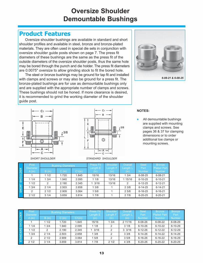
Oversize ShoulderDemountable Bushings
NOTES:
♦ All demountable bushingsare supplied with mountingclamps and screws. Seepages 36 & 37 for clampingdimensions or to orderadditional toe clamps ormounting screws.
Oversize shoulder bushings are available in standard and shortshoulder profiles and available in steel, bronze and bronze-platedmaterials. They are often used in special die sets in conjunction withoversize shoulder guide posts shown on page 7. The press fitdiameters of these bushings are the same as the press fit of theoutside diameters of the oversize shoulder posts, thus the same holemay be bored through the punch and die holder. The press fit diametersare 0.0075" oversize to allow grinding stock to fit the bored hole.
The steel or bronze bushings may be ground for tap fit and installedwith clamps and screws or may also be ground for a press fit. Thebronze-plated bushings are for use as demountable bushings onlyand are supplied with the appropriate number of clamps and screws.These bushings should not be honed. If more clearance is desired,it is recommended to grind the working diameter of the shoulderguide post.
Product Features
6-08-21 & 6-08-25
SHORT SHOULDER STANDARD SHOULDER
Post Bushing Diameters Press Fit Shoulder Overall Steel BronzeDiameter Length E Length F Length L Part Plated Part
A (in) B (in) C (in) C1(in) (in) (in) (in) Number Number1 1 1/2 1.720 1.845 15/16 13/16 1 3/4 6-08-25 6-08-21
1 1/4 1 3/4 1.940 2.095 1 1/8 13/16 1 15/16 6-10-25 6-10-211 1/2 2 2.190 2.345 1 3/16 13/16 2 6-12-25 6-12-211 3/4 2 1/4 2.503 2.658 1 3/8 1 2 3/8 6-14-25 6-14-21
2 2 1/2 2.909 3.064 1 5/8 1 2 5/8 6-16-25 6-16-212 1/2 3 1/4 3.659 3.814 1 7/8 1 2 7/8 6-20-25 6-20-21
SHO
RT
SHO
ULD
ER
Post Bushing Diameters Press Fit Shoulder Overall Steel Bronze BronzeDiameter Length E Length F Length L Part Plated Part Part
A (in) B (in) C (in) C1(in) (in) (in) (in) Number Number Number1 1 1/2 1.720 1.845 15/16 1 3/4 2 11/16 6-08-26 6-08-22 6-08-29
1 1 1/4 1 3/4 1.940 2.095 1 1/8 2 3 1/8 6-10-26 6-10-22 6-10-291 1 1/2 2 2.190 2.345 1 3/16 2 3 3/16 6-12-26 6-12-22 6-12-291 1 3/4 2 1/4 2.503 2.658 1 3/8 2 3 3/8 6-14-26 6-14-22 6-14-29
2 2 1/2 2.909 3.064 1 5/8 2 3 5/8 6-16-26 6-16-22 6-16-292 1/2 3 1/4 3.659 3.814 1 7/8 2 1/2 4 3/8 6-20-26 6-20-22 6-20-29ST
AN
DA
RD
SH
OU
LDER

14
Press Fit Bushings
These press fit bushings are available in short shoulder, shortsleeve and long sleeve profiles. Manufactured from high qualityhardened steel, the bushings are finish ground for a press fit. Bushings1 ¾" in diameter and smaller are finish ground 0.0006" under listedinside diameters to allow for honing at assembly. Bushings with insidediameters 2" and larger are finished ground to decimal diameters. Allbushings are also equipped with oil grooves and lubrication fittings.
Product Features
6-08-03 & 6-08-01
Post Outside OverallDiameter A Diameter B Length L Part
(in) (in) (in) Number1/2 13/16 3 6-04-35/8 1 3 6-05-33/4 1 1/8 3 6-06-37/8 1 3/8 3 6-07-31 1 1/2 3 6-08-3
1 1/4 1 3/4 3 6-10-31 1/2 2 3 6-12-31 3/4 2 1/4 3 6-14-3
2 2 1/2 3 6-16-32 1/2 3 1/4 3 6-20-3
EXTR
A L
ON
G S
LEEV
E
Post Outside OverallDiameter A Diameter B Length L Part
(in) (in) (in) Number1/2 13/16 1 1/2 6-04-15/8 1 1 1/2 6-05-13/4 1 1/8 1 3/4 6-06-17/8 1 3/8 1 3/4 6-07-11 1 1/2 1 3/4 6-08-1
1 1/4 1 3/4 2 6-10-11 1/2 2 2 6-12-1
SHO
RT
SLEE
VE
Post Press Fit Bushing Press Fit Shoulder OverallDiameter A Diameter B Diameter C Length E Length F Length L Part
(in) (in) (in) (in) (in) (in) Number1/2 13/16 1.062 11/16 13/16 1 1/2 6-04-615/8 1 1.218 11/16 13/16 1 1/2 6-05-613/4 1 1/8 1.375 15/16 13/16 1 3/4 6-06-617/8 1 3/8 1.625 15/16 13/16 1 3/4 6-07-61SH
OR
T SH
OU
LDER
15
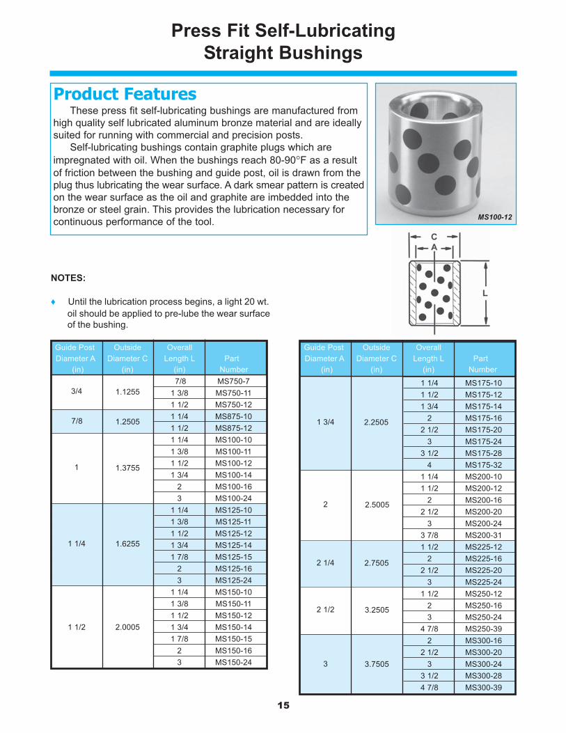
Press Fit Self-LubricatingStraight Bushings
These press fit self-lubricating bushings are manufactured fromhigh quality self lubricated aluminum bronze material and are ideallysuited for running with commercial and precision posts.
Self-lubricating bushings contain graphite plugs which areimpregnated with oil. When the bushings reach 80-90°F as a resultof friction between the bushing and guide post, oil is drawn from theplug thus lubricating the wear surface. A dark smear pattern is createdon the wear surface as the oil and graphite are imbedded into thebronze or steel grain. This provides the lubrication necessary forcontinuous performance of the tool.
Product Features
MS100-12
NOTES:
♦ Until the lubrication process begins, a light 20 wt.oil should be applied to pre-lube the wear surfaceof the bushing.
1.1255 7/8 MS750-7 3/4 1.1255 1 3/8 MS750-11 3/4 1.1255 1 1/2 MS750-12 7/8 1.2505 1 1/4 MS875-10 7/8 1.2505 1 1/2 MS875-12
1 1.3755 1 1/4 MS100-101 1.3755 1 3/8 MS100-111 1.3755 1 1/2 MS100-121 1.3755 1 3/4 MS100-141 1.3755 2 MS100-161 1.3755 3 MS100-24
1 1/4 1.6255 1 1/4 MS125-101 1/4 1.6255 1 3/8 MS125-111 1/4 1.6255 1 1/2 MS125-121 1/4 1.6255 1 3/4 MS125-141 1/4 1.6255 1 7/8 MS125-151 1/4 1.6255 2 MS125-161 1/4 1.6255 3 MS125-241 1/2 2.0005 1 1/4 MS150-101 1/2 2.0005 1 3/8 MS150-111 1/2 2.0005 1 1/2 MS150-121 1/2 2.0005 1 3/4 MS150-141 1/2 2.0005 1 7/8 MS150-151 1/2 2.0005 2 MS150-16
3 MS150-24
Guide Post Outside OverallDiameter A Diameter C Length L Part
(in) (in) (in) Number
1
1 1/2
7/8
1 1/4
1.2505
1.6255
2.0005
1.3755
3/4 1.12551 3/4 2.2505 1 1/4 MS175-101 3/4 2.2505 1 1/2 MS175-121 3/4 2.2505 1 3/4 MS175-141 3/4 2.2505 2 MS175-161 3/4 2.2505 2 1/2 MS175-201 3/4 2.2505 3 MS175-241 3/4 2.2505 3 1/2 MS175-281 3/4 2.2505 4 MS175-32
2 2.5005 1 1/4 MS200-102 2.5005 1 1/2 MS200-122 2.5005 2 MS200-162 2.5005 2 1/2 MS200-202 2.5005 3 MS200-242 2.5005 3 7/8 MS200-31
2 1/4 2.7505 1 1/2 MS225-122 1/4 2.7505 2 MS225-162 1/4 2.7505 2 1/2 MS225-202 1/4 2.7505 3 MS225-242 1/2 3.2505 1 1/2 MS250-122 1/2 3.2505 2 MS250-162 1/2 3.2505 3 MS250-242 1/2 3.2505 4 7/8 MS250-39
3 3.7505 2 MS300-163 3.7505 2 1/2 MS300-203 3.7505 3 MS300-243 3.7505 3 1/2 MS300-283 3.7505 4 7/8 MS300-39
Guide Post Outside OverallDiameter A Diameter C Length L Part
(in) (in) (in) Number
2 1/2
2
3
2 1/4
1 3/4
3.2505
2.5005
2.2505
2.7505
3.7505

16
Post Press Fit Outside Press Fit Overall Self-Diameter Diameter Diameter Length Length Lubricating
A (in) B (in) C (in) E (in) L (in) Part No.
3/4 1.1255 1.30 11/16 7/8 S750-7G3/4 1.1255 1.30 1 3/16 1 3/8 S750-11G3/4 1.1255 1.30 1 11/16 1 7/8 S750-15G3/4 1.1255 1.30 2 3/16 2 3/8 S750-19G3/4 1.1255 1.30 2 11/16 2 7/8 S750-23G3/4 1.1255 1.30 3 3/16 3 3/8 S750-27G3/4 1.1255 1.30 3 11/16 3 7/8 S750-31G3/4 1.1255 1.30 4 3/16 4 3/8 S750-35G3/4 1.1255 1.30 4 11/16 4 7/8 S750-39G7/8 1.2505 1.43 11/16 7/8 S875-7G7/8 1.2505 1.43 1 3/16 1 3/8 S875-11G7/8 1.2505 1.43 1 11/16 1 7/8 S875-15G7/8 1.2505 1.43 2 3/16 2 3/8 S875-19G7/8 1.2505 1.43 2 11/16 2 7/8 S875-23G7/8 1.2505 1.43 3 3/16 3 3/8 S875-27G7/8 1.2505 1.43 3 11/16 3 7/8 S875-31G7/8 1.2505 1.43 4 3/16 4 3/8 S875-35G1 1.3755 1.55 11/16 7/8 S1000-7G1 1.3755 1.55 1 3/16 1 3/8 S1000-11G1 1.3755 1.55 1 11/16 1 7/8 S1000-15G1 1.3755 1.55 2 3/16 2 3/8 S1000-19G1 1.3755 1.55 2 11/16 2 7/8 S1000-23G1 1.3755 1.55 3 3/16 3 3/8 S1000-27G1 1.3755 1.55 3 11/16 3 7/8 S1000-31G1 1.3755 1.55 4 3/16 4 3/8 S1000-35G1 1.3755 1.55 4 11/16 4 7/8 S1000-39G1 1.3755 1.55 5 11/16 5 7/8 S1000-47G
1 1/4 1.6255 1.80 11/16 7/8 S1250-7G1 1/4 1.6255 1.80 1 3/16 1 3/8 S1250-11G1 1/4 1.6255 1.80 1 11/16 1 7/8 S1250-15G1 1/4 1.6255 1.80 2 3/16 2 3/8 S1250-19G1 1/4 1.6255 1.80 2 11/16 2 7/8 S1250-23G1 1/4 1.6255 1.80 3 3/16 3 3/8 S1250-27G1 1/4 1.6255 1.80 3 11/16 3 7/8 S1250-31G1 1/4 1.6255 1.80 4 3/16 4 3/8 S1250-35G
Press Fit Self-LubricatingShoulder Bushings
These press fit self-lubricating bushings are manufactured fromhigh quality self lubricated aluminum bronze material and are ideallysuited for running with commercial and precision posts.
Self-lubricating bushings contain graphite plugs which areimpregnated with oil. When the bushings reach 80-90°F as a resultof friction between the bushing and guide post, oil is drawn from theplug thus lubricating the wear surface. A dark smear pattern is createdon the wear surface as the oil and graphite are imbedded into thebronze or steel grain. This provides the lubrication necessary forcontinuous performance of the tool.
Product Features
S1000-34G
1 1/4 1.6255 1.80 4 11/16 4 7/8 S1250-39G1 1/4 1.6255 1.80 5 11/16 5 7/8 S1250-47G1 1/2 2.0005 2.18 11/16 7/8 S1500-7G1 1/2 2.0005 2.18 1 3/16 1 3/8 S1500-11G1 1/2 2.0005 2.18 1 11/16 1 7/8 S1500-15G1 1/2 2.0005 2.18 2 3/16 2 3/8 S1500-19G1 1/2 2.0005 2.18 2 11/16 2 7/8 S1500-23G1 1/2 2.0005 2.18 3 3/16 3 3/8 S1500-27G1 1/2 2.0005 2.18 3 11/16 3 7/8 S1500-31G1 1/2 2.0005 2.18 4 3/16 4 3/8 S1500-35G1 1/2 2.0005 2.18 4 11/16 4 7/8 S1500-39G1 1/2 2.0005 2.18 5 11/16 5 7/8 S1500-47G
2 2.5005 2.68 1 3/16 1 3/8 S2000-11G2 2.5005 2.68 1 11/16 1 7/8 S2000-15G2 2.5005 2.68 2 3/16 2 3/8 S2000-19G2 2.5005 2.68 2 11/16 2 7/8 S2000-23G2 2.5005 2.68 3 3/16 3 3/8 S2000-27G2 2.5005 2.68 3 11/16 3 7/8 S2000-31G2 2.5005 2.68 4 3/16 4 3/8 S2000-35G2 2.5005 2.68 4 11/16 4 7/8 S2000-39G2 2.5005 2.68 5 11/16 5 7/8 S2000-47G
2 1/2 3.2505 3.43 1 3/16 1 3/8 S2500-11G2 1/2 3.2505 3.43 1 11/16 1 7/8 S2500-15G2 1/2 3.2505 3.43 2 3/16 2 3/8 S2500-19G2 1/2 3.2505 3.43 2 11/16 2 7/8 S2500-23G2 1/2 3.2505 3.43 3 3/16 3 3/8 S2500-27G2 1/2 3.2505 3.43 3 11/16 3 7/8 S2500-31G2 1/2 3.2505 3.43 4 3/16 4 3/8 S2500-35G2 1/2 3.2505 3.43 4 11/16 4 7/8 S2500-39G2 1/2 3.2505 3.43 5 11/16 5 7/8 S2500-47G
3 3.7505 3.99 3 3/16 3 3/8 S3000-27G3 3.7505 3.99 3 11/16 3 7/8 S3000-31G3 3.7505 3.99 4 11/16 4 7/8 S3000-39G3 3.7505 3.99 5 11/16 5 7/8 S3000-47G
Post Press Fit Outside Press Fit Overall Self-Diameter Diameter Diameter Length Length Lubricating
A (in) B (in) C (in) E (in) L (in) Part No.
3 3.7505 3.99
1 1/2 2.0005 2.18
2 1/2 3.2505 3.43
2 2.5005 2.68
1 1/4 1.6255 1.80
7/8 1.2505 1.43
1 1/4 1.6255 1.80
1 1.3755 1.55
3/4 1.1255 1.30
17
6-16-19
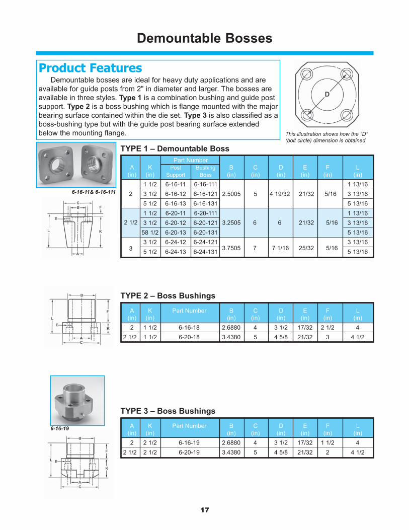
Demountable Bosses
Demountable bosses are ideal for heavy duty applications and areavailable for guide posts from 2" in diameter and larger. The bosses areavailable in three styles. Type 1 is a combination bushing and guide postsupport. Type 2 is a boss bushing which is flange mounted with the majorbearing surface contained within the die set. Type 3 is also classified as aboss-bushing type but with the guide post bearing surface extendedbelow the mounting flange.
Product Features
TYPE 1 – Demountable Boss
This illustration shows how the “D”(bolt circle) dimension is obtained.
TYPE 2 – Boss Bushings
TYPE 3 – Boss Bushings
6-16-11& 6-16-111
Part NumberA K Post Bushing B C D E F L
(in) (in) Support Boss (in) (in) (in) (in) (in) (in)(in)2 1 1/2 6-16-11 6-16-111 2.5005 5 4 19/32 21/32 5/16 1 13/16
3 1/2 6-16-12 6-16-121 3 13/165 1/2 6-16-13 6-16-131 5 13/16
2 1/2 1 1/2 6-20-11 6-20-111 3.2505 6 6 21/32 5/16 1 13/163 1/2 6-20-12 6-20-121 3 13/16
58 1/2 6-20-13 6-20-131 5 13/163 3 1/2 6-24-12 6-24-121 3.7505 7 7 1/16 25/32 5/16 3 13/16
5 1/2 6-24-13 6-24-131 5 13/16
2
3
2.5005 5 4 19/32 21/32 5/16
3.7505 7 7 1/16 25/32 5/16
2 1/2 3.2505 6 6 21/32 5/16
A K Part Number B C D E F L(in) (in) (in) (in) (in) (in) (in) (in)2 1 1/2 6-16-18 2.6880 4 3 1/2 17/32 2 1/2 4
2 1/2 1 1/2 6-20-18 3.4380 5 4 5/8 21/32 3 4 1/2
A K Part Number B C D E F L(in) (in) (in) (in) (in) (in) (in) (in)2 2 1/2 6-16-19 2.6880 4 3 1/2 17/32 1 1/2 4
2 1/2 2 1/2 6-20-19 3.4380 5 4 5/8 21/32 2 4 1/2

18
Ball Bearing Cages
6-0808-822
Ball cages are manufactured from a heat treated aluminum alloywhich provides tough, wear resistant qualities. The ball bearings arevacuum degassed quality, fatigue resistant steel and are inspectedto ensure roundness, smoothness and dimensional conformance.The ball bearings are arranged in the cage in a spiral pattern tominimize tracking or grooving and assure uniform wear. Ball cagesare mounted to drilled and tapped guide posts by a special washerassembly which permits the cage to rotate freely around the guidepost when not under pre-load.
Product Features
TYPE IFor Type I
Ball BearingBushing Assembly
TYPE IIFor Type II and Type III
Ball BearingBushing Assemblies
Posts Length Type I Type IIDiameter C S X Part Part
O (in) (in) (in) (in) Number Number1 3/4 4 3/4 2 7/16 1/4 — 6-1419-8221 3/4 5 1/4 2 15/16 1/4 — 6-1421-8221 3/4 5 3/4 3 7/16 1/4 — 6-1423-8221 3/4 6 1/4 3 15/16 1/4 — 6-1425-8221 3/4 6 3/4 4 7/16 1/4 — 6-1427-822
2 3 1 3/16 1/4 6-1612-821 —2 3 1/2 1 7/16 1/4 6-1614-821 —2 3 3/4 1 15/16 1/4 — 6-1615-8222 4 1/2 2 5/16 1/4 — 6-1618-8222 5 1/4 2 11/16 1/4 — 6-1621-8222 5 5/8 3 1/16 1/4 — 6-1623-8222 6 3 7/16 1/4 — 6-1624-8222 6 1/2 3 15/16 1/4 — 6-1626-8222 7 4 7/16 1/4 — 6-1628-8222 7 1/2 4 15/16 1/4 — 6-1630-822
2 1/2 4 1 11/16 3/8 6-2016-821 —2 1/2 5 3/4 3 3/8 — 6-2023-8222 1/2 6 1/2 3 3/8 3/8 — 6-2026-8222 1/2 7 1/4 3 3/4 3/8 — 6-2029-8222 1/2 7 3/4 4 1/4 3/8 — 6-2031-8222 1/2 8 1/4 4 3/4 3/8 — 6-2033-8222 1/2 8 3/4 5 1/4 3/8 — 6-2035-822
3 4 1 11/16 3/8 6-2416-821 —3 5 3/4 3 3/8 — 6-2423-8223 6 1/2 3 3/8 3/8 — 6-2426-8223 7 1/4 3 3/4 3/8 — 6-2429-8223 7 3/4 4 1/4 3/8 — 6-2431-8223 8 1/4 4 3/4 3/8 — 6-2433-8223 8 3/4 5 1/4 3/8 — 6-2435-822
3 3/8
2 1/2 3/8
2 1/4
1 3/4 1/4
Posts Length Type I Type IIDiameter C S X Part Part
O (in) (in) (in) (in) Number Number1 1 1/2 7/16 3/16 6-0806-821 —1 2 11/16 3/16 6-0808-821 —1 2 1 1/16 3/16 — 6-0808-8221 2 1/2 1 5/16 3/16 — 6-0810-8221 3 1 9/16 3/16 — 6-0812-8221 3 1/4 1 13/16 3/16 — 6-0813-8221 3 1/2 2 1/16 3/16 — 6-0814-8221 3 3/4 2 5/16 3/16 — 6-0815-822
1 1/4 1 1/2 7/16 3/16 6-1006-821 —1 1/4 2 11/16 3/16 6-1008-821 —1 1/4 2 3/4 1 7/16 3/16 — 6-1011-8221 1/4 3 1/4 1 11/16 3/16 — 6-1013-8221 1/4 3 3/4 1 15/16 3/16 — 6-1015-8221 1/4 4 2 3/16 3/16 — 6-1016-8221 1/4 4 1/4 2 7/16 3/16 — 6-1017-8221 1/4 4 3/4 2 15/16 3/16 — 6-1019-8221 1/2 2 11/16 1/4 6-1208-821 —1 1/2 2 1/2 15/16 1/4 6-1210-821 —1 1/2 2 3/4 1 7/16 1/4 — 6-1211-8221 1/2 3 1/2 1 13/16 1/4 — 6-1214-8221 1/2 4 1/4 2 3/16 1/4 — 6-1217-8221 1/2 4 1/2 2 7/16 1/4 — 6-1218-8221 1/2 5 2 15/16 1/4 — 6-1220-8221 1/2 5 1/2 3 7/16 1/4 — 6-1222-8221 1/2 6 3 15/16 1/4 — 6-1224-8221 3/4 2 1/2 15/16 1/4 6-1410-821 —1 3/4 3 1 3/16 1/4 6-1412-821 —1 3/4 3 1/4 1 11/16 1/4 — 6-1413-8221 3/4 4 2 1/16 1/4 — 6-1416-822
1 3/16
1 1/4 3/16
1 1/2 1/4
1 3/4 1/4

19
Ball BearingPress Fit Guide Posts
Precision ball bearing guide posts are manufacturedfrom hardened steel to assure free rolling of balls andhigh wear resistance. Each post is drilled and tappedat the bottom for mounting of the ball cage washerassembly. This unique mounting method permits theball cage, except when under pre-load, to freely rotate360 degrees around the guide post thus eliminatingscoring or tracking of the guide post surface.
Product Features
NOTES:
♦ Ball Cage washer assembly sold separatelyand dependent on Type I, II or III assemblymethods. Refer to page 34 for washerassembly part numbers.
5-0820-82
Diameter Length PartO (in) L (in) Number
1 3 1/4 5-0813-821 3 3/4 5-0815-821 4 1/4 5-0817-821 4 1/2 5-0818-821 4 3/4 5-0819-821 5 5-0820-821 5 1/4 5-0821-821 5 1/2 5-0822-821 5 3/4 5-0823-821 6 5-0824-821 6 1/2 5-0826-821 7 5-0828-821 7 1/2 5-0830-821 8 5-0832-821 8 1/2 5-0834-821 9 5-0836-82
1 1/4 4 1/4 5-1017-821 1/4 4 3/4 5-1019-821 1/4 5 1/4 5-1021-821 1/4 5 1/2 5-1022-821 1/4 5 3/4 5-1023-821 1/4 6 5-1024-821 1/4 6 1/2 5-1026-821 1/4 7 5-1028-821 1/4 7 1/2 5-1030-821 1/4 8 5-1032-821 1/4 8 1/2 5-1034-821 1/4 9 5-1036-821 1/4 10 5-1040-821 1/4 11 5-1044-821 1/4 12 5-1048-821 1/2 4 1/4 5-1217-821 1/2 5 5-1220-821 1/2 5 3/4 5-1223-821 1/2 6 5-1224-821 1/2 6 1/2 5-1226-821 1/2 7 5-1228-82
1 1/4
1
1 1/2
Diameter Length PartO (in) L (in) Number1 1/2 7 1/2 5-1230-821 1/2 8 5-1232-821 1/2 8 1/2 5-1234-821 1/2 9 5-1236-821 1/2 9 1/2 5-1238-821 1/2 10 5-1240-821 1/2 10 1/2 5-1242-821 1/2 11 5-1244-821 1/2 11 1/2 5-1246-821 1/2 12 5-1248-821 1/2 12 1/2 5-1250-821 1/2 13 5-1252-821 1/2 14 5-1256-821 3/4 5 5-1420-821 3/4 5 3/4 5-1423-821 3/4 6 1/2 5-1426-821 3/4 7 5-1428-821 3/4 7 1/2 5-1430-821 3/4 8 5-1432-821 3/4 8 1/2 5-1434-821 3/4 9 5-1436-821 3/4 9 1/2 5-1438-821 3/4 10 5-1440-821 3/4 10 1/2 5-1442-821 3/4 11 5-1444-821 3/4 11 1/2 5-1446-821 3/4 12 5-1448-821 3/4 12 1/2 5-1450-821 3/4 13 5-1452-821 3/4 14 5-1456-821 3/4 15 5-1460-821 3/4 17 5-1468-82
2 5 3/4 5-1623-822 6 1/2 5-1626-822 7 1/4 5-1629-822 7 1/2 5-1630-822 7 3/4 5-1631-82
1 3/4
2
1 1/2
2 8 5-1632-822 8 1/2 5-1634-822 9 5-1636-822 9 1/2 5-1638-822 10 5-1640-822 10 1/2 5-1642-822 11 5-1644-822 11 1/2 5-1646-822 12 5-1648-822 12 1/2 5-1650-822 13 5-1652-822 14 5-1656-822 15 5-1660-822 16 5-1664-822 17 5-1668-822 18 5-1672-82
2 1/2 8 5-2032-822 1/2 8 3/4 5-2035-822 1/2 9 1/2 5-2038-822 1/2 10 5-2040-822 1/2 11 5-2044-822 1/2 12 5-2048-822 1/2 13 5-2052-822 1/2 14 5-2056-822 1/2 17 5-2068-822 1/2 18 5-2072-822 1/2 20 5-2080-82
3 8 1/2 5-2434-823 9 1/4 5-2437-823 10 5-2440-823 11 5-2444-823 12 5-2448-823 13 5-2452-823 14 5-2456-823 17 5-2468-823 20 5-2480-82
Diameter Length PartO (in) L (in) Number
2 1/2
3
2

20
Ball Bearing DemountableGuide Posts
5-0813-826
Precision ball bearing guide posts are manufactured from hardenedsteel to assure free rolling of balls and high wear resistance. Eachpost is drilled and tapped at the bottom for mounting of the ball cagewasher assembly. This unique mounting method permits the ball cage,except when under pre-load, to freely rotate 360 degrees around theguide post thus eliminating scoring or tracking of the guide postsurface.
Demountable posts are tap fit and held in place with toe clampsand screws. They can be removed and assembled multiple timeswithout damaging or distorting the mounting holes in the die set thussimplifying die building and maintenance. Demountable posts arealso used to replace press fit posts when the press fit hole has beendamaged and the straight pin no longer fits securely in the hole.
Product Features
NOTES:
♦ All Ball Cage washer assemblysold separately and dependent onType I, II or III assembly methods.Refer to page 34 for washerassembly part numbers.
♦ All demountable guide posts aresupplied with mounting clampsand screws. See pages 36 & 37for clamping dimensions or toorder additional toe clamps ormounting screws.

21
Ball Bearing DemountableGuide Posts
1 1 5/16 1 3/16 2 1/2 5-0810-8261 1 5/16 1 3/16 2 3/4 5-0811-8261 1 5/16 1 3/16 3 5-0812-8261 1 5/16 1 3/16 3 1/4 5-0813-8261 1 5/16 1 3/16 3 1/2 5-0814-8261 1 5/16 1 3/16 3 3/4 5-0815-8261 1 5/16 1 3/16 4 5-0816-8261 1 5/16 1 3/16 4 1/4 5-0817-8261 1 5/16 1 3/16 4 1/2 5-0818-8261 1 5/16 1 3/16 4 3/4 5-0819-8261 1 5/16 1 3/16 5 1/4 5-0821-8261 1 5/16 1 3/16 5 3/4 5-0823-8261 1 5/16 1 3/16 6 1/4 5-0825-8261 1 5/16 1 3/16 6 3/4 5-0827-8261 1 5/16 1 3/16 7 1/4 5-0829-8261 1 5/16 1 3/16 7 3/4 5-0831-826
1 1/4 1 9/16 1 3/16 3 1/4 5-1013-8261 1/4 1 9/16 1 3/16 3 1/2 5-1014-8261 1/4 1 9/16 1 3/16 3 3/4 5-1015-8261 1/4 1 9/16 1 3/16 4 5-1016-8261 1/4 1 9/16 1 3/16 4 1/4 5-1017-8261 1/4 1 9/16 1 3/16 4 1/2 5-1018-8261 1/4 1 9/16 1 3/16 4 3/4 5-1019-8261 1/4 1 9/16 1 3/16 5 1/4 5-1021-8261 1/4 1 9/16 1 3/16 5 3/4 5-1023-8261 1/4 1 9/16 1 3/16 6 1/4 5-1025-8261 1/4 1 9/16 1 3/16 6 3/4 5-1027-8261 1/4 1 9/16 1 3/16 7 1/4 5-1029-8261 1/4 1 9/16 1 3/16 7 3/4 5-1031-8261 1/4 1 9/16 1 3/16 8 3/4 5-1035-8261 1/4 1 9/16 1 3/16 9 3/4 5-1039-8261 1/4 1 9/16 1 3/16 10 3/4 5-1043-8261 1/2 1 7/8 1 7/16 3 1/4 5-1213-8261 1/2 1 7/8 1 7/16 3 1/2 5-1214-8261 1/2 1 7/8 1 7/16 3 3/4 5-1215-8261 1/2 1 7/8 1 7/16 4 5-1216-8261 1/2 1 7/8 1 7/16 4 1/4 5-1217-8261 1/2 1 7/8 1 7/16 4 1/2 5-1218-8261 1/2 1 7/8 1 7/16 5 5-1220-8261 1/2 1 7/8 1 7/16 5 1/2 5-1222-8261 1/2 1 7/8 1 7/16 6 5-1224-8261 1/2 1 7/8 1 7/16 6 1/2 5-1226-8261 1/2 1 7/8 1 7/16 7 5-1228-8261 1/2 1 7/8 1 7/16 7 1/2 5-1230-8261 1/2 1 7/8 1 7/16 8 5-1232-8261 1/2 1 7/8 1 7/16 8 1/2 5-1234-8261 1/2 1 7/8 1 7/16 9 5-1236-8261 1/2 1 7/8 1 7/16 9 1/2 5-1238-8261 1/2 1 7/8 1 7/16 10 5-1240-8261 1/2 1 7/8 1 7/16 10 1/2 5-1242-8261 1/2 1 7/8 1 7/16 11 5-1244-8261 1/2 1 7/8 1 7/16 11 1/2 5-1246-8261 1/2 1 7/8 1 7/16 12 1/2 5-1250-8261 3/4 2 1/4 1 11/16 3 3/4 5-1415-8261 3/4 2 1/4 1 11/16 4 5-1416-8261 3/4 2 1/4 1 11/16 4 1/4 5-1417-8261 3/4 2 1/4 1 11/16 4 1/2 5-1418-8261 3/4 2 1/4 1 11/16 4 3/4 5-1419-8261 3/4 2 1/4 1 11/16 5 1/4 5-1421-826
Diameter Diameter Press Fit WorkingO B Length Length Part
(in) (in) E1 (in) F1 (in) Number
1 1/4 1 9/16 1 3/16
1 3/4 2 1/4 1 11/16
1 1/2 1 7/8 1 7/16
1 1 5/16 1 3/16
1 3/4 2 1/4 1 11/16 5 3/4 5-1423-8261 3/4 2 1/4 1 11/16 6 1/4 5-1425-8261 3/4 2 1/4 1 11/16 6 3/4 5-1427-8261 3/4 2 1/4 1 11/16 7 1/4 5-1429-8261 3/4 2 1/4 1 11/16 7 3/4 5-1431-8261 3/4 2 1/4 1 11/16 8 1/4 5-1433-8261 3/4 2 1/4 1 11/16 8 3/4 5-1435-8261 3/4 2 1/4 1 11/16 9 1/4 5-1437-8261 3/4 2 1/4 1 11/16 9 3/4 5-1439-8261 3/4 2 1/4 1 11/16 10 1/4 5-1441-8261 3/4 2 1/4 1 11/16 10 3/4 5-1443-8261 3/4 2 1/4 1 11/16 11 1/4 5-1445-8261 3/4 2 1/4 1 11/16 12 1/4 5-1449-8261 3/4 2 1/4 1 11/16 13 1/4 5-1453-8261 3/4 2 1/4 1 11/16 14 1/4 5-1457-8261 3/4 2 1/4 1 11/16 15 1/4 5-1461-826
2 2 1/2 1 15/16 4 1/4 5-1617-8262 2 1/2 1 15/16 4 1/2 5-1618-8262 2 1/2 1 15/16 4 3/4 5-1619-8262 2 1/2 1 15/16 5 5-1620-8262 2 1/2 1 15/16 5 1/4 5-1621-8262 2 1/2 1 15/16 5 1/2 5-1622-8262 2 1/2 1 15/16 5 3/4 5-1623-8262 2 1/2 1 15/16 6 5-1624-8262 2 1/2 1 15/16 6 1/2 5-1626-8262 2 1/2 1 15/16 7 5-1628-8262 2 1/2 1 15/16 7 1/2 5-1630-8262 2 1/2 1 15/16 8 5-1632-8262 2 1/2 1 15/16 8 1/2 5-1634-8262 2 1/2 1 15/16 9 5-1636-8262 2 1/2 1 15/16 9 1/2 5-1638-8262 2 1/2 1 15/16 10 5-1640-8262 2 1/2 1 15/16 10 1/2 5-1642-8262 2 1/2 1 15/16 11 5-1644-8262 2 1/2 1 15/16 12 5-1648-8262 2 1/2 1 15/16 13 5-1652-8262 2 1/2 1 15/16 14 5-1656-8262 2 1/2 1 15/16 15 5-1660-8262 2 1/2 1 15/16 16 5-1664-826
2 1/2 3 1/32 1 15/16 6 5-2024-8262 1/2 3 1/32 1 15/16 6 1/2 5-2026-8262 1/2 3 1/32 1 15/16 7 5-2028-8262 1/2 3 1/32 1 15/16 8 5-2032-8262 1/2 3 1/32 1 15/16 9 5-2036-8262 1/2 3 1/32 1 15/16 10 5-2040-8262 1/2 3 1/32 1 15/16 11 5-2044-8262 1/2 3 1/32 1 15/16 12 5-2048-8262 1/2 3 1/32 1 15/16 15 5-2060-8262 1/2 3 1/32 1 15/16 18 5-2072-826
3 3 1/2 2 7/16 6 5-2424-8263 3 1/2 2 7/16 6 1/2 5-2426-8263 3 1/2 2 7/16 7 1/2 5-2430-8263 3 1/2 2 7/16 8 1/2 5-2434-8263 3 1/2 2 7/16 9 1/2 5-2438-8263 3 1/2 2 7/16 10 1/2 5-2442-8263 3 1/2 2 7/16 11 1/2 5-2446-8263 3 1/2 2 7/16 14 1/2 5-2458-8263 3 1/2 2 7/16 17 1/2 5-2470-826
Diameter Diameter Press Fit WorkingO B Length Length Part
(in) (in) E1 (in) F1(in) Number
2 1/2 3 1/32 1 15/16
1 3/4 2 1/4 1 11/16
2 2 1/2 1 15/16
3 3 1/2 2 7/16

22
Ball BearingDemountable Bushings
6-0807-85
These demountable bushings are tap fit into location and seatflush with the ground face of the punch holder. The bushings areheld in place with toe clamps and screws which provide perfectalignment of the bushing with the bore perpendicular to the groundsurface of the punch holder. The clamp and screws provide fourtimes the holding power compared to pressed-in bushings, yet theycan be easily removed and assembled thus simplifying die buildingand maintenance.
Product Features
Post OverallDiameter Bushing Diameters Length E Length F Length Part
(in) A (in) B (in) C (in) C1 (in) (in) (in) L1 (in) Number1 1 3/8 1 7/8 2 1/8 2.283 1 3/16 1 1/4 2 7/16 6-0805-851 1 3/8 1 7/8 2 1/8 2.283 1 3/16 1 3/4 2 15/16 6-0807-851 1 3/8 1 7/8 2 1/8 2.283 1 3/16 2 1/4 3 7/16 6-0809-851 1 3/8 1 7/8 2 1/8 2.283 1 3/16 2 3/4 3 15/16 6-0811-85
1 1/4 1 5/8 2 1/8 2 3/8 2.533 1 3/16 1 3/4 2 15/16 6-1007-851 1/4 1 5/8 2 1/8 2 3/8 2.533 1 3/16 2 1/4 3 7/16 6-1009-851 1/4 1 5/8 2 1/8 2 3/8 2.533 1 3/16 2 3/4 3 15/16 6-1011-851 1/2 1 7/8 2 1/2 2 7/8 3.033 1 7/16 1 1/2 2 15/16 6-1206-851 1/2 1 7/8 2 1/2 2 7/8 3.033 1 7/16 2 1/4 3 11/16 6-1209-851 1/2 1 7/8 2 1/2 2 7/8 3.033 1 7/16 3 4 7/16 6-1212-851 1/2 1 7/8 2 1/2 2 7/8 3.033 1 7/16 3 1/2 4 15/16 6-1214-851 3/4 2 1/8 2 3/4 3 1/8 3.283 1 11/16 1 3/4 3 7/16 6-1407-851 3/4 2 1/8 2 3/4 3 1/8 3.283 1 11/16 2 1/2 4 3/16 6-1410-851 3/4 2 1/8 2 3/4 3 1/8 3.283 1 11/16 3 1/4 4 15/16 6-1413-85
2 2 1/2 3 1/4 3 5/8 3.783 1 15/16 2 3 15/16 6-1608-852 2 1/2 3 1/4 3 5/8 3.783 1 15/16 2 3/4 4 11/16 6-1611-852 2 1/2 3 1/4 3 5/8 3.783 1 15/16 3 1/2 5 7/16 6-1614-852 2 1/2 3 1/4 3 5/8 3.783 1 15/16 4 1/4 6 3/16 6-1617-852 2 1/2 3 1/4 3 5/8 3.783 1 15/16 5 6 15/16 6-1620-85
2 1/2 3 3 3/4 4 1/8 4.283 1 15/16 4 5 15/16 6-2016-852 1/2 3 3 3/4 4 1/8 4.283 1 15/16 4 3/4 6 11/16 6-2019-852 1/2 3 3 3/4 4 1/8 4.283 1 15/16 5 1/2 7 7/16 6-2022-85
3 1/2 4 1/4 4 3/4 4.908 1 15/16 4 5 15/16 6-2416-853 3 1/2 4 1/4 4 3/4 4.908 1 15/16 4 3/4 6 11/16 6-2419-853 3 1/2 4 1/4 4 3/4 4.908 1 15/16 5 1/2 7 7/16 6-2422-85
1 1/4 1 5/8 2 1/8 2 3/8 2.533 1 3/16
1 3/41 3/4 2 1/8 2 3/4 3 1/8 3.283 1 11/16
2 1/2 3 3 3/4 4 1/8 4.283 1 15/16
3 3 1/2 4 1/4 4 3/4 4.908 1 15/16
2 2 1/2 3 1/4 3 5/8 3.783 1 15/16
1 1/2 1 7/8 2 1/2 2 7/8 3.033 1 7/16
1 1 3/8 1 7/8 2 1/8 2.283 1 3/16

23
6-0814-86
Ball BearingStraight Sleeve Bushings
Straight sleeve bushings are manufactured from high qualityhardened steel and the bushings are finish ground for a press fit.Like all ball bearing components, these straight sleeve bushings arecompletely interchangeable.
Product Features
INSTALLATION INSTRUCTIONS
In order to avoid the bushing close-in which occurs as a result of press-fit, these bushings should be retained with Danly Bushing Mount. When soinstalled, it is not necessary to hone the bushing bore after installation, andthe bushing fit will be correct.
APPLICATION OF DANLY BUSHING MOUNT1. Degrease bushing OD and die shoe bore with alcohol, acetone or other
volatile solvent and wipe dry.2. Apply Bushing Mount sparingly and wring bushing into die shoe.3. Allow a 4-hour cure at 72° F. Do not disturb bushing until cure is complete.
DANLY BUSHING MOUNT: Part number 9-60-82
1 3/4 2 1/8 2 3/4 6 6-1424-861 3/4 2 1/8 2 3/4 7 6-1428-861 3/4 2 1/8 2 3/4 8 6-1432-861 3/4 2 1/8 2 3/4 9 6-1436-86
2 2 1/2 3 1/4 4 6-1616-862 2 1/2 3 1/4 4 3/4 6-1619-862 2 1/2 3 1/4 5 1/2 6-1622-862 2 1/2 3 1/4 6 1/4 6-1625-862 2 1/2 3 1/4 7 6-1628-862 2 1/2 3 1/4 8 6-1632-862 2 1/2 3 1/4 9 6-1636-862 2 1/2 3 1/4 10 6-1640-86
2 1/2 3 3 3/4 6 6-2024-862 1/2 3 3 3/4 6 3/4 6-2027-862 1/2 3 3 3/4 7 1/2 6-2030-862 1/2 3 3 3/4 8 1/2 6-2034-862 1/2 3 3 3/4 9 1/2 6-2038-862 1/2 3 3 3/4 10 1/2 6-2042-86
3 3 1/2 4 1/4 6 6-2424-863 3 1/2 4 1/4 6 3/4 6-2427-863 3 1/2 4 1/4 7 1/2 6-2430-863 3 1/2 4 1/4 8 1/2 6-2434-863 3 1/2 4 1/4 9 1/2 6-2438-863 3 1/2 4 1/4 10 1/2 6-2442-86
PostDiameter Bushing Diameters Length Part
(in) A (in) B (in) L2 (in) Number
2 1/2 3 3 3/4
1 3/4 2 1/8 2 3/4
2 2 1/2 3 1/4
3 3 1/2 4 1/4
1 1 3/8 1 7/8 2 1/2 6-0810-861 1 3/8 1 7/8 3 6-0812-861 1 3/8 1 7/8 3 1/2 6-0814-861 1 3/8 1 7/8 4 6-0816-861 1 3/8 1 7/8 4 1/2 6-0818-861 1 3/8 1 7/8 5 6-0820-86
1 1/4 1 5/8 2 1/8 3 6-1012-861 1/4 1 5/8 2 1/8 3 1/2 6-1014-861 1/4 1 5/8 2 1/8 4 6-1016-861 1/4 1 5/8 2 1/8 4 1/2 6-1018-861 1/4 1 5/8 2 1/8 5 6-1020-861 1/4 1 5/8 2 1/8 6 6-1024-861 1/2 1 7/8 2 1/2 3 6-1212-861 1/2 1 7/8 2 1/2 3 3/4 6-1215-861 1/2 1 7/8 2 1/2 4 1/2 6-1218-861 1/2 1 7/8 2 1/2 5 6-1220-861 1/2 1 7/8 2 1/2 5 1/2 6-1222-861 1/2 1 7/8 2 1/2 6 6-1224-861 1/2 1 7/8 2 1/2 7 6-1228-861 1/2 1 7/8 2 1/2 8 6-1232-861 3/4 2 1/8 2 3/4 3 1/2 6-1414-861 3/4 2 1/8 2 3/4 4 1/4 6-1417-861 3/4 2 1/8 2 3/4 5 6-1420-861 3/4 2 1/8 2 3/4 5 1/2 6-1422-86
PostDiameter Bushing Diameters Length Part
(in) A (in) B (in) L2 (in) Number
1 1/4 1 5/8 2 1/8
1 3/4 2 1/8 2 3/4
1 1 3/8 1 7/8
1 1/2 1 7/8 2 1/2

24
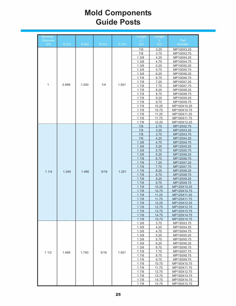
Mold ComponentsGuide Posts
Mold component products include a hardened & ground steelguide post ideally suited for running with the self-lubricating moldbushing shown on page 26.
Product Features
MP875x3.25
Nominal Length LengthDiameter L1 L Part
(in) D (in) A (in) B (in) C (in) (in) (in) Number 3/4 0.749 0.990 3/16 0.751 7/8 1.75 MP750X1.75 3/4 0.749 0.990 3/16 0.751 7/8 2.25 MP750X2.25 3/4 0.749 0.990 3/16 0.751 7/8 2.75 MP750X2.75 3/4 0.749 0.990 3/16 0.751 7/8 3.25 MP750X3.25 3/4 0.749 0.990 3/16 0.751 7/8 3.75 MP750X3.75 3/4 0.749 0.990 3/16 0.751 1 3/8 4.25 MP750X4.25 3/4 0.749 0.990 3/16 0.751 1 3/8 4.75 MP750X4.75 3/4 0.749 0.990 3/16 0.751 1 3/8 5.25 MP750X5.25 3/4 0.749 0.990 3/16 0.751 1 7/8 5.75 MP750X5.75 3/4 0.749 0.990 3/16 0.751 1 7/8 6.25 MP750X6.25 3/4 0.749 0.990 3/16 0.751 1 7/8 6.75 MP750X6.75 3/4 0.749 0.990 3/16 0.751 1 7/8 7.25 MP750X7.25 3/4 0.749 0.990 3/16 0.751 1 7/8 7.75 MP750X7.75 3/4 0.749 0.990 3/16 0.751 1 7/8 9.25 MP750X9.25 7/8 0.874 1.115 1/4 0.876 7/8 1.75 MP875X1.75 7/8 0.874 1.115 1/4 0.876 7/8 2.25 MP875X2.25 7/8 0.874 1.115 1/4 0.876 7/8 2.75 MP875X2.75 7/8 0.874 1.115 1/4 0.876 7/8 3.25 MP875X3.25 7/8 0.874 1.115 1/4 0.876 7/8 3.75 MP875X3.75 7/8 0.874 1.115 1/4 0.876 1 3/8 4.25 MP875X4.25 7/8 0.874 1.115 1/4 0.876 1 3/8 4.75 MP875X4.75 7/8 0.874 1.115 1/4 0.876 1 3/8 5.25 MP875X5.25 7/8 0.874 1.115 1/4 0.876 1 3/8 5.75 MP875X5.75 7/8 0.874 1.115 1/4 0.876 1 7/8 6.25 MP875X6.25 7/8 0.874 1.115 1/4 0.876 1 7/8 6.75 MP875X6.75 7/8 0.874 1.115 1/4 0.876 1 7/8 7.25 MP875X7.25 7/8 0.874 1.115 1/4 0.876 1 7/8 7.75 MP875X7.75 7/8 0.874 1.115 1/4 0.876 1 7/8 8.25 MP875X8.25 7/8 0.874 1.115 1/4 0.876 1 7/8 8.75 MP875X8.75 7/8 0.874 1.115 1/4 0.876 1 7/8 10.75 MP875X10.75 7/8 0.874 1.115 1/4 0.876 1 7/8 12.25 MP875X12.25
1 0.999 1.240 1/4 1.001 7/8 1.75 MP100X1.751 0.999 1.240 1/4 1.001 7/8 2.25 MP100X2.251 0.999 1.240 1/4 1.001 7/8 2.75 MP100X2.75
7/8 0.874 1.115 1/4 0.876
1 0.999 1.240 1/4 1.001
3/4 0.749 0.990 3/16 0.751
25
Mold ComponentsGuide Posts
1 0.999 1.240 1/4 1.001 7/8 3.25 MP100X3.251 0.999 1.240 1/4 1.001 7/8 3.75 MP100X3.751 0.999 1.240 1/4 1.001 1 3/8 4.25 MP100X4.251 0.999 1.240 1/4 1.001 1 3/8 4.75 MP100X4.751 0.999 1.240 1/4 1.001 1 3/8 5.25 MP100X5.251 0.999 1.240 1/4 1.001 1 3/8 5.75 MP100X5.751 0.999 1.240 1/4 1.001 1 3/8 6.25 MP100X6.251 0.999 1.240 1/4 1.001 1 7/8 6.75 MP100X6.751 0.999 1.240 1/4 1.001 1 7/8 7.25 MP100X7.251 0.999 1.240 1/4 1.001 1 7/8 7.75 MP100X7.751 0.999 1.240 1/4 1.001 1 7/8 8.25 MP100X8.251 0.999 1.240 1/4 1.001 1 7/8 8.75 MP100X8.751 0.999 1.240 1/4 1.001 1 7/8 9.25 MP100X9.251 0.999 1.240 1/4 1.001 1 7/8 9.75 MP100X9.751 0.999 1.240 1/4 1.001 1 7/8 10.25 MP100X10.251 0.999 1.240 1/4 1.001 1 7/8 10.75 MP100X10.751 0.999 1.240 1/4 1.001 1 7/8 11.25 MP100X11.251 0.999 1.240 1/4 1.001 1 7/8 11.75 MP100X11.751 0.999 1.240 1/4 1.001 1 7/8 12.25 MP100X12.25
1 1/4 1.249 1.490 5/16 1.251 7/8 2.75 MP125X2.751 1/4 1.249 1.490 5/16 1.251 7/8 3.25 MP125X3.251 1/4 1.249 1.490 5/16 1.251 7/8 3.75 MP125X3.751 1/4 1.249 1.490 5/16 1.251 7/8 4.25 MP125X4.251 1/4 1.249 1.490 5/16 1.251 1 3/8 4.75 MP125X4.751 1/4 1.249 1.490 5/16 1.251 1 3/8 5.25 MP125X5.251 1/4 1.249 1.490 5/16 1.251 1 3/8 5.75 MP125X5.751 1/4 1.249 1.490 5/16 1.251 1 3/8 6.25 MP125X6.251 1/4 1.249 1.490 5/16 1.251 1 7/8 6.75 MP125X6.751 1/4 1.249 1.490 5/16 1.251 1 7/8 7.25 MP125X7.251 1/4 1.249 1.490 5/16 1.251 1 7/8 7.75 MP125X7.751 1/4 1.249 1.490 5/16 1.251 1 7/8 8.25 MP125X8.251 1/4 1.249 1.490 5/16 1.251 1 7/8 8.75 MP125X8.751 1/4 1.249 1.490 5/16 1.251 1 7/8 9.25 MP125X9.251 1/4 1.249 1.490 5/16 1.251 1 7/8 9.75 MP125X9.751 1/4 1.249 1.490 5/16 1.251 1 7/8 10.25 MP125X10.251 1/4 1.249 1.490 5/16 1.251 1 7/8 10.75 MP125X10.751 1/4 1.249 1.490 5/16 1.251 1 7/8 11.25 MP125X11.251 1/4 1.249 1.490 5/16 1.251 1 7/8 11.75 MP125X11.751 1/4 1.249 1.490 5/16 1.251 1 7/8 12.25 MP125X12.251 1/4 1.249 1.490 5/16 1.251 1 7/8 12.75 MP125X12.751 1/4 1.249 1.490 5/16 1.251 1 7/8 13.75 MP125X13.751 1/4 1.249 1.490 5/16 1.251 1 7/8 14.75 MP125X14.751 1/4 1.249 1.490 5/16 1.251 1 7/8 15.75 MP125X15.751 1/2 1.499 1.740 5/16 1.501 1 3/8 3.75 MP150X3.751 1/2 1.499 1.740 5/16 1.501 1 3/8 4.25 MP150X4.251 1/2 1.499 1.740 5/16 1.501 1 3/8 4.75 MP150X4.751 1/2 1.499 1.740 5/16 1.501 1 3/8 5.25 MP150X5.251 1/2 1.499 1.740 5/16 1.501 1 3/8 5.75 MP150X5.751 1/2 1.499 1.740 5/16 1.501 1 3/8 6.25 MP150X6.251 1/2 1.499 1.740 5/16 1.501 1 3/8 6.75 MP150X6.751 1/2 1.499 1.740 5/16 1.501 1 7/8 7.75 MP150X7.751 1/2 1.499 1.740 5/16 1.501 1 7/8 8.75 MP150X8.751 1/2 1.499 1.740 5/16 1.501 1 7/8 9.75 MP150X9.751 1/2 1.499 1.740 5/16 1.501 1 7/8 10.75 MP150X10.751 1/2 1.499 1.740 5/16 1.501 1 7/8 11.75 MP150X11.751 1/2 1.499 1.740 5/16 1.501 1 7/8 12.75 MP150X12.751 1/2 1.499 1.740 5/16 1.501 1 7/8 13.75 MP150X13.751 1/2 1.499 1.740 5/16 1.501 1 7/8 14.75 MP150X14.751 1/2 1.499 1.740 5/16 1.501 1 7/8 15.75 MP150X15.75
Nominal Length LengthDiameter L1 L Part
(in) D (in) A (in) B (in) C (in) (in) (in) Number
1 1/4 1.249 1.490 5/16 1.251
1 0.999 1.240 1/4 1.001
1 1/2 1.499 1.740 5/16 1.501

26
ME1000L
Mold Components –Self-Lubricating Ejector Bushings
Mold component products feature self-lubricating aluminum bronzebushings ideally suited for running with the MP line of Guide Posts.
These self-lubricating bushings contain graphite plugs which areimpregnated with oil. When the bushings reach 80-90°F as a result offriction between the bushing and guide post, oil is drawn from the plugthus lubricating the wear surface. A dark smear pattern is created onthe wear surface as the oil and graphite are imbedded into the bronzeor steel grain. This provides the lubrication necessary for continuousperformance of the tool.
Product Features
Part Nom.Number I.D. D (in) A (in) B (in) C (in) L1 (in) L (in)ME750 3/4 .751 1.1255 1.124 1.302 1 1 1/2ME875 7/8 .876 1.2505 1.249 1.427 1 1 1/2
ME1000 1 1.001 1.3755 1.374 1.552 1 1/8 1 3/4ME1000L 1 1.001 1.3755 1.374 1.552 1 5/8 2ME1250 1 1/4 1.251 1.6255 1.624 1.802 1 1/8 1 3/4
ME1250L 1 1/4 1.251 1.6255 1.624 1.802 1 7/8 2 1/2ME1500 1 1/2 1.501 2.0005 1.999 2.177 1 1/8 1 3/4
ME1500L 1 1/2 1.501 2.0005 1.999 2.177 1 7/8 2 1/2ME2000 2 2.001 2.5005 2.499 2.687 1 5/8 2 1/4
1 1.001 1.3755 1.374 1.552
1 1/4 1.251 1.6255 1.624 1.802
1 1/2 1.501 2.0005 1.999 2.177

27
Ball Bearing ComponentsSelection Guide
Type IFull Pre-Load
Throughout Stroke
Type I component assembliesensure that all ball bearingsremain in constant contact withthe guide post and bushingthroughout the entire press stroke.This assembly is recommendedfor higher speed, short strokedies.
Type IIPre-Load Relived
or Partially Relieved
Type II component assemblies aredesigned so the ball cage neverleaves the bushing; however theguide post disengages thebushing at the beginning of eachstroke. This assembly is oftenpreferred as pinch points areeliminated and foreign mattercannot get inside the assemblyand damage the components.This assembly is often utilized inmedium and long stroke dies.
Type IIITotal Disengagementof Cage from Bushing
Type III component assembliesare designed so the ball cagetotally disengages from thebushing. This assembly is utilizedon long stroke applications.
Product FeaturesFor proper post, bushing and cage selection, the operating conditions
of the die must be taken into consideration. Factors such as pressspeed, shut height, stroke length and operating environment all playa role in selecting the appropriate operating condition to give the bestperformance possible of your components. The operating conditionsinclude full pre-load, pre-load relieved and total disengagement.

28
Type IComponent Selection Guide
PRESS FIT POSTS1. Calculate L, the desired guide post length, using one of the following 2 formulas:
Assembly with Straight Sleeve Bushings: L=T-U2-ZAssembly with Demountable Bushings: L=T-U1-Z-J+E
2. Select a post length from the catalog that is equal to L calculated above. If the calculated L value is not astandard catalog length, you have two options. Choose the next longest length and cut off to the calculated Ldimension or select a shorter length and recess the post in the punch holder to obtain correct L dimension.Note: Press fit length should be equal to or greater than the diameter of the guide post.
DEMOUNTABLE POSTS1. Calculate F1, the desired guide post length, using one of the following 2 formulas:
Assembly with Straight Sleeve Bushings: F1=T-U2-Z-K (Note F+J+K+Y<T)Assembly with Demountable Bushing: F1=T-U1-Z-J+E-K (Note L2+K+Y<T)
2. Select a post length from the catalog that is equal to F1 calculated above. If the calculated F1 value is not astandard catalog length, choose a catalog length that is close to but less than the calculated F1.Note: Demountable posts cannot be cut off.
BUSHING & CAGE SELECTIONSelection of a Type 1 ball bearing bushing and cage assembly
is based on the required stroke and the guide post diameter.1. Determine the guide post diameter required and the stroke required.2. Using the selection chart on page 29, find the desired stroke. Move down this column to the colored square on
the horizontal line opposite the required post diameter.3. Select the required bushing length which is listed to the left of the selected square in the columns labeled
demountable shoulder and straight sleeve.Note: For applications with no off-center loading, select the bushing with the shortest overall length from theselection chart. However for longer stroke applications or where side-loading may be present select thebushing with the longest possible length to provide optimal guidance.
4. Select the required cage length which is also listed to the left of the selected square in the column labeled“Ball Cage.”Note: Shut height permitting, select the longest cage length possible for optimal performance.
NOTES:
♦ If die grind is not required, stroke may beincreased by the amount of die grind allowance,dimension X, found in the right most column ofthe selection chart.
NOTES:
♦ A die set designed for a particular stroke may beused in any press of lesser stroke but never inany press where the stroke is greater thanoriginally chosen.
Post Diam. Z E U1 U2
(in) (in) (in) (in) (in)1 5/16 1 3/16 1/16 1/8
1 1/4 5/16 1 3/161 1/2 3/8 1 7/161 3/4 3/8 1 11/16
2 3/8 1 15/162 1/2 1/2 1 15/16
3 1/2 1 15/16
1/16 1/8

29
Type IComponent Selection Guide
30
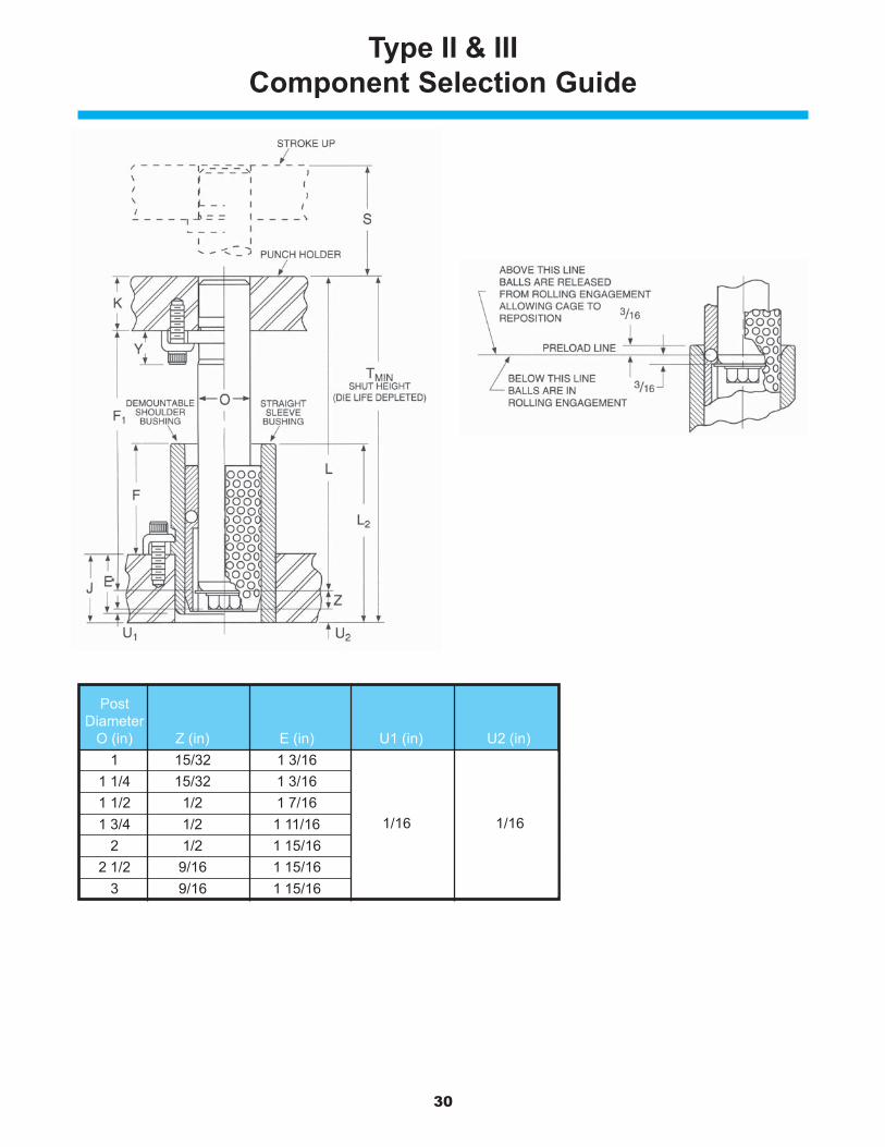
Type II & IIIComponent Selection Guide
PostDiameter
O (in) Z (in) E (in) U1 (in) U2 (in)1 15/32 1 3/16
1 1/4 15/32 1 3/161 1/2 1/2 1 7/161 3/4 1/2 1 11/16 1/16 1/16
2 1/2 1 15/162 1/2 9/16 1 15/16
3 9/16 1 15/16
1/16 1/16

31
Type II & IIIComponent Selection Guide
PRESS FIT POSTS1. Calculate L, the desired guide post length, using one of the following 2 formulas:
Assembly with Straight Sleeve Bushings: L=T-U2-ZAssembly with Demountable Bushings: L=T-U1-Z-J+E
2. Select a post length from the catalog that is equal to L calculated above. If the calculated L valueis not a standard catalog length, you have two options. Choose the next longest length and cut offto the calculated L dimension or select a shorter length and recess the post in the punch holder toobtain correct L dimension.Note: Press fit length should be equal to or greater than the diameter of the guide post.
DEMOUNTABLE POSTS1. Calculate F1, the desired guide post length, using one of the following 2 formulas:
Assembly with Straight Sleeve Bushings: F1=T-U2-Z-K (Note F+J+K+Y<T)Assembly with Demountable Bushings: F1=T-U1-Z-J+E-K (Note L2+K+Y<T)
2. Select a post length from the catalog that is equal to F1 calculated above. If the calculated F1 valueis not a standard catalog length, choose a catalog length that is close to but less than thecalculated F1.Note: Demountable posts cannot be cut off.
BUSHING & CAGE SELECTIONSelection of a Type II and Type III ball bearing bushing and cage assembly
is based on the required stroke and the guide post diameter.1. Determine the guide post diameter required and the stroke required.2. Determine the desired operating condition or the extent to which the cage leaves the bushing.3. Determine if a demountable or straight sleeve bushing is to be used.4. Using the selection chart on pages 32 & 33, find the desired stroke (S). Move down this column to
the colored square on the horizontal line opposite the required post diameter. Find the coloredsquare in the desired operating condition.
5. Select the required bushing length which is listed to the left of the selected square in the columnslabeled demountable shoulder or straight sleeve.Note: For applications with no off-center loading, select the bushing with the shortest overalllength from the selection chart. However for longer stroke applications or where side-loading maybe present select the bushing with the longest possible length to provide optimal guidance.
6. Select the required cage length which is also listed to the left of the selected square in the columnlabeled “Ball Cage.”Note: Shut height permitting, select the longest cage length possible for optimal performance.
NOTES:
♦ A die set designed for a particular stroke may beused in any press of lesser stroke but never inany press where the stroke is greater thanoriginally chosen.

32
Type II & IIIBushing & Ball Cage Selection Guide
CAUTION
Be sure bushing does not strike punch holder at minimumshut height. If this condition exists, use shorter bushing andcorresponding ball cage.
NOTES:
♦ Sleeve Bushing: L2 + K must be less than T
♦ Shoulder Bushing: J + F + K must be less than T
♦ Demountable Bushing: Maximum F = T - J - K
♦ Sleeve Bushing: Maximum L2 = T - K 3 1 15/16
Nom. Ball Bushing BallPost Demountable Shoulder Straight Sleeve Cage
Diam.O E F L1 U1 L2 U2 C1 1 3/16 1 1/4 2 7/16 1/16 2 1/2 1/8 2
1 3/4 2 15/16 3 2 1/2
2 1/4 3 7/16 3 1/2 3
2 3/4 3 15/16 4 3 1/4
– – 4 1/2 3 1/2
– – 5 3 3/4
1 1/4 1 3/16 1 3/4 2 15/16 1/16 3 1/8 2 3/4
2 1/4 3 7/16 3 1/2 3 1/4
2 3/4 3 15/16 4 3 3/4
– – 4 1/2 4
– – 5 4 1/4
– – 6 4 3/4
1 1/2 1 7/16 1 1/2 2 15/16 1/16 3 1/8 2 3/4
2 1/4 3 11/16 3 3/4 3 1/2
3 4 7/16 4 1/2 4 1/4
3 1/2 4 15/16 5 4 1/2
– – 6 5
– – 7 5 1/2
– – 8 6
1 3/4 1 11/16 1 3/4 3 7/16 1/16 3 1/2 1/8 3 1/4
2 1/2 4 3/16 4 1/4 4
3 1/4 4 15/16 5 4 3/4
– – 6 5 1/4
– – 7 5 3/4
– – 8 6 1/4
– – 9 6 3/4
2 1 15/16 2 3 15/16 1/16 4 1/8 3 3/4
2 3/4 4 11/16 4 3/4 4 1/2
3 1/2 5 7/16 5 1/2 5 1/4
4 1/4 6 3/16 6 1/4 5 5/8
5 6 15/16 7 6
– – 8 6 1/2
– – 9 7
– – 10 7 1/2
2 1/2 1 15/16 4 5 15/16 1/16 6 1/8 5 3/4
4 3/4 6 11/16 6 3/4 6 1/2
5 1/2 7 7/16 7 1/2 7 1/4
– – 8 1/2 7 3/4
– – 9 1/2 8 1/4
– – 10 1/2 8 3/4
3 1 15/16 4 5 15/16 1/16 6 1/8 5 3/4
4 3/4 6 11/16 6 3/4 6 1/2
5 1/2 7 7/16 7 1/2 7 1/4
– – 8 1/2 7 3/4
– – 9 1/2 8 1/4
– – 10 1/2 8 3/4
1 1 3/16
1 1/4 1 3/16
1 1/2 1 7/16
1 3/4 1 11/16
2 1 15/16
2 1/2 1 15/16
1/16 1/8
1/16
1/16
1/16
1/16
1/16
1/16
1/8
1/8
1/8
1/8
1/8
1/8
COLOR CODE FOR SELECTION GUIDEType II and III components provide
Type I operating conditions
Partial Pre-load
Pre-load Relieved
Unlimited stroke cageleaves bushing

33
Type II & IIIBushing & Ball Cage Selection Guide
1/2
1 1 1/
2
2 2 1/
2
3 3 1/
2
4 4 1/
2
5 5 1/
2
6 6 1/
2
7 7 1/
2
8 9 10 11 12 13 14 15 16
7/8
1 1/8
3
3 1/4
3 1/2
3 3/4
1 1/4
1 1/2
3 3/4
4
4 1/4
4 3/4
1 1/4
1 5/8
4 1/4
4 1/2
5
5 1/2
6
1 1/2
1 7/8
4 3/4
5 1/4
5 3/4
6 1/4
6 3/4
1 3/4
1 1/8
5 1/4
5 5/8
6
6 1/2
7
7 1/2
2 11/16
3 1/16
7 1/4
7 3/4
8 1/4
8 3/4
2 11/16
3 1/16
7 1/4
7 3/4
8 1/4
8 3/4
1 3/8
1 3/4
2 1/2
3 7/16
3 7/16
STROKE “S” AT MINIMUM SHUT HEIGHT (DIE LIFE DEPLETED)V
2
2 1/2
3
3 1/4
3 1/2
3 3/4
2 3/4
3 1/4
3 3/4
4
4 1/4
4 3/4
2 3/4
3 2/3
4 1/4
4 1/2
5
5 1/2
6
3 1/4
4
4 3/4
5 1/4
5 3/4
6 1/4
6 3/4
3 3/4
4 1/2
5 1/4
5 5/8
6
6 1/2
7
7 1/2
5 3/4
6 1/2
7 1/4
7 3/4
8 1/4
8 3/4
5 3/4
6 1/2
7 1/4
7 3/4
8 1/4
8 3/4
BallCage
C
2
2 1/4
33
34
Ball Bearing ComponentsTechnical Information
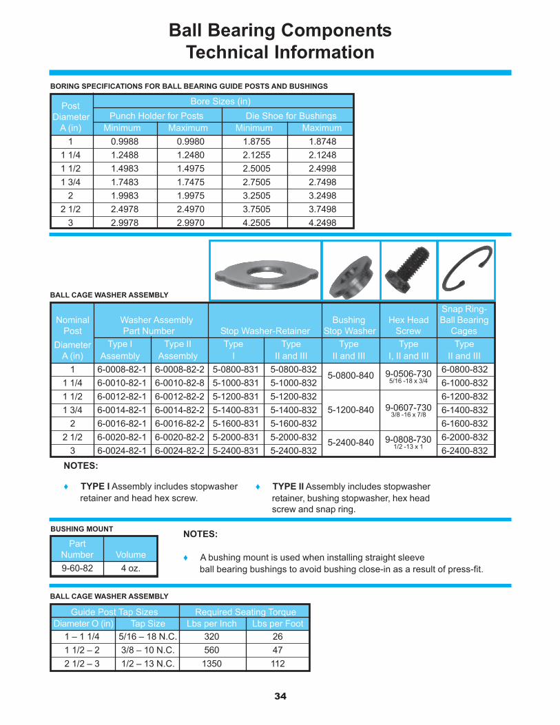
BORING SPECIFICATIONS FOR BALL BEARING GUIDE POSTS AND BUSHINGS
BUSHING MOUNT
BALL CAGE WASHER ASSEMBLY
NOTES:
♦ A bushing mount is used when installing straight sleeveball bearing bushings to avoid bushing close-in as a result of press-fit.
BALL CAGE WASHER ASSEMBLY
NOTES:
♦ TYPE I Assembly includes stopwasherretainer and head hex screw.
♦ TYPE II Assembly includes stopwasherretainer, bushing stopwasher, hex headscrew and snap ring.
Snap Ring-Nominal Washer Assembly Bushing Hex Head Ball Bearing
Post Part Number Stop Washer-Retainer Stop Washer Screw CagesDiameter Type I Type II Type Type Type Type Type
A (in) Assembly Assembly I II and III II and III I, II and III II and III1 6-0008-82-1 6-0008-82-2 5-0800-831 5-0800-832 5-0800-840 9-0506-730 6-0800-832
1 1/4 6-0010-82-1 6-0010-82-8 5-1000-831 5-1000-832 6-1000-8321 1/2 6-0012-82-1 6-0012-82-2 5-1200-831 5-1200-832 5-1200-840 9-0607-730 6-1200-8321 3/4 6-0014-82-1 6-0014-82-2 5-1400-831 5-1400-832 6-1400-832
2 6-0016-82-1 6-0016-82-2 5-1600-831 5-1600-832 6-1600-8322 1/2 6-0020-82-1 6-0020-82-2 5-2000-831 5-2000-832 5-2400-840 9-0808-730 6-2000-832
3 6-0024-82-1 6-0024-82-2 5-2400-831 5-2400-832 6-2400-832
5-0800-840
5-1200-840
5-2400-840
9-0506-7305/16 -18 x 3/4
9-0607-7303/8 -16 x 7/8
9-0808-7301/2 -13 x 1
Post Bore Sizes (in)
Diameter Punch Holder for Posts Die Shoe for BushingsA (in) Minimum Maximum Minimum Maximum
1 0.9988 0.9980 1.8755 1.87481 1/4 1.2488 1.2480 2.1255 2.12481 1/2 1.4983 1.4975 2.5005 2.49981 3/4 1.7483 1.7475 2.7505 2.7498
2 1.9983 1.9975 3.2505 3.24982 1/2 2.4978 2.4970 3.7505 3.7498
3 2.9978 2.9970 4.2505 4.2498
Guide Post Tap Sizes Required Seating Torque Diameter O (in) Tap Size Lbs per Inch Lbs per Foot
1 – 1 1/4 5/16 – 18 N.C. 320 261 1/2 – 2 3/8 – 10 N.C. 560 472 1/2 – 3 1/2 – 13 N.C. 1350 112
PartNumber Volume9-60-82 4 oz.
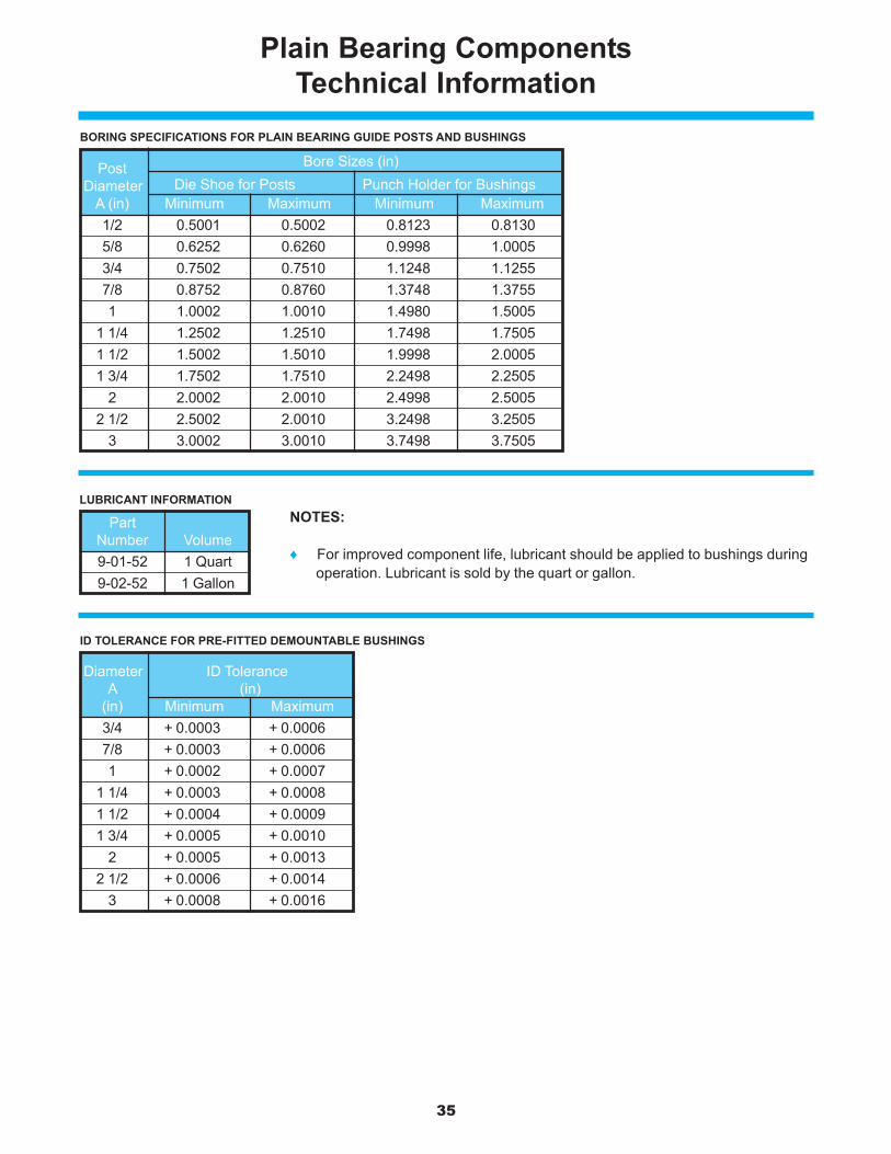
35
Plain Bearing ComponentsTechnical Information
LUBRICANT INFORMATION
ID TOLERANCE FOR PRE-FITTED DEMOUNTABLE BUSHINGS
NOTES:
♦ For improved component life, lubricant should be applied to bushings duringoperation. Lubricant is sold by the quart or gallon.
BORING SPECIFICATIONS FOR PLAIN BEARING GUIDE POSTS AND BUSHINGS
Post Bore Sizes (in)
Diameter Die Shoe for Posts Punch Holder for BushingsA (in) Minimum Maximum Minimum Maximum1/2 0.5001 0.5002 0.8123 0.81305/8 0.6252 0.6260 0.9998 1.00053/4 0.7502 0.7510 1.1248 1.12557/8 0.8752 0.8760 1.3748 1.37551 1.0002 1.0010 1.4980 1.5005
1 1/4 1.2502 1.2510 1.7498 1.75051 1/2 1.5002 1.5010 1.9998 2.00051 3/4 1.7502 1.7510 2.2498 2.2505
2 2.0002 2.0010 2.4998 2.50052 1/2 2.5002 2.0010 3.2498 3.2505
3 3.0002 3.0010 3.7498 3.7505
PartNumber Volume9-01-52 1 Quart9-02-52 1 Gallon
Diameter ID ToleranceA (in)
(in) Minimum Maximum3/4 + 0.0003 + 0.00067/8 + 0.0003 + 0.00061 + 0.0002 + 0.0007
1 1/4 + 0.0003 + 0.00081 1/2 + 0.0004 + 0.00091 3/4 + 0.0005 + 0.0010
2 + 0.0005 + 0.00132 1/2 + 0.0006 + 0.0014
3 + 0.0008 + 0.0016
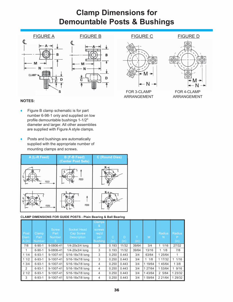
36
Clamps&
Screw Socket Head screwsPost Clamp Part Cap Screw req'd Radius Radius
Diam. Part Number Description per C D T M N PA (in) Number S Bushing (in) (in) (in) (in)7/8 6-90-1 9-0806-41 1/4-20x3/4 long 3 0.193 11/32 39/64 3/4 1 1/16 27/321 6-90-1 9-0806-41 1/4-20x3/4 long 3 0.193 11/32 39/64 13/16 1 1/8 7/8
1 1/4 6-93-1 9-1007-41 5/16-18x7/8 long 3 0.250 0.443 3/4 63/64 1 25/64 11 1/2 6-93-1 9-1007-41 5/16-18x7/8 long 3 0.250 0.443 3/4 1 1/8 1 17/32 1 1/161 3/4 6-93-1 9-1007-41 5/16-18x7/8 long 4 0.250 0.443 3/4 1 19/64 1 45/64 1 3/8
2 6-93-1 9-1007-41 5/16-18x7/8 long 4 0.250 0.443 3/4 1 27/64 1 53/64 1 9/162 1/2 6-93-1 9-1007-41 5/16-18x7/8 long 4 0.250 0.443 3/4 1 43/64 2 5/64 1 23/32
3 6-93-1 9-1007-41 5/16-18x7/8 long 4 0.250 0.443 3/4 1 59/64 2 21/64 1 29/32
Clamp Dimensions forDemountable Posts & Bushings
NOTES:
♦ Figure B clamp schematic is for partnumber 6-98-1 only and supplied on lowprofile demountable bushings 1-1/2"diameter and larger. All other assembliesare supplied with Figure A style clamps.
♦ Posts and bushings are automaticallysupplied with the appropriate number ofmounting clamps and screws.
FIGURE A FIGURE B
CLAMP DIMENSIONS FOR GUIDE POSTS - Plain Bearing & Ball Bearing
FIGURE C FIGURE D
S FOR 3-CLAMP FOR 4-CLAMPARRANGEMENT ARRANGEMENT
A (L-R Feed) B (F-B Feed) C (Round Dies)(Center Post Sets)
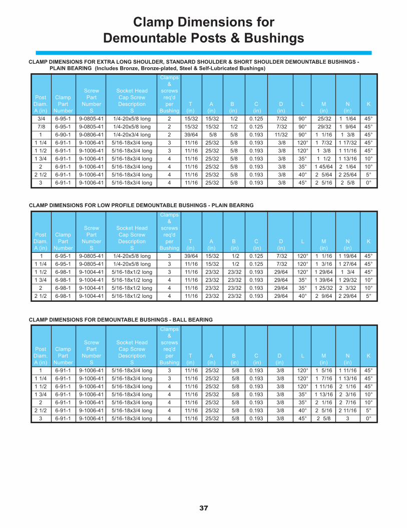
37
Clamp Dimensions forDemountable Posts & Bushings
CLAMP DIMENSIONS FOR EXTRA LONG SHOULDER, STANDARD SHOULDER & SHORT SHOULDER DEMOUNTABLE BUSHINGS -PLAIN BEARING (Includes Bronze, Bronze-plated, Steel & Self-Lubricated Bushings)
CLAMP DIMENSIONS FOR LOW PROFILE DEMOUNTABLE BUSHINGS - PLAIN BEARING
CLAMP DIMENSIONS FOR DEMOUNTABLE BUSHINGS - BALL BEARING
Clamps&
Screw Socket Head screwsPost Clamp Part Cap Screw req'd
Diam. Part Number Description per T A B C D L M N KA (in) Number S S Bushing (in) (in) (in) (in) (in) (in) (in)
1 6-91-1 9-1006-41 5/16-18x3/4 long 3 11/16 25/32 5/8 0.193 3/8 120° 1 5/16 1 11/16 45°1 1/4 6-91-1 9-1006-41 5/16-18x3/4 long 3 11/16 25/32 5/8 0.193 3/8 120° 1 7/16 1 13/16 45°1 1/2 6-91-1 9-1006-41 5/16-18x3/4 long 4 11/16 25/32 5/8 0.193 3/8 120° 1 11/16 2 1/16 45°1 3/4 6-91-1 9-1006-41 5/16-18x3/4 long 4 11/16 25/32 5/8 0.193 3/8 35° 1 13/16 2 3/16 10°
2 6-91-1 9-1006-41 5/16-18x3/4 long 4 11/16 25/32 5/8 0.193 3/8 35° 2 1/16 2 7/16 10°2 1/2 6-91-1 9-1006-41 5/16-18x3/4 long 4 11/16 25/32 5/8 0.193 3/8 40° 2 5/16 2 11/16 5°
3 6-91-1 9-1006-41 5/16-18x3/4 long 4 11/16 25/32 5/8 0.193 3/8 45° 2 5/8 3 0°
Clamps&
Screw Socket Head screwsPost Clamp Part Cap Screw req'd
Diam. Part Number Description per T A B C D L M N KA (in) Number S S Bushing (in) (in) (in) (in) (in) (in) (in)
1 6-95-1 9-0805-41 1/4-20x5/8 long 3 39/64 15/32 1/2 0.125 7/32 120° 1 1/16 1 19/64 45°1 1/4 6-95-1 9-0805-41 1/4-20x5/8 long 3 11/16 15/32 1/2 0.125 7/32 120° 1 3/16 1 27/64 45°1 1/2 6-98-1 9-1004-41 5/16-18x1/2 long 3 11/16 23/32 23/32 0.193 29/64 120° 1 29/64 1 3/4 45°1 3/4 6-98-1 9-1004-41 5/16-18x1/2 long 4 11/16 23/32 23/32 0.193 29/64 35° 1 39/64 1 29/32 10°
2 6-98-1 9-1004-41 5/16-18x1/2 long 4 11/16 23/32 23/32 0.193 29/64 35° 1 25/32 2 3/32 10°2 1/2 6-98-1 9-1004-41 5/16-18x1/2 long 4 11/16 23/32 23/32 0.193 29/64 40° 2 9/64 2 29/64 5°
Clamps&
Screw Socket Head screwsPost Clamp Part Cap Screw req'd
Diam. Part Number Description per T A B C D L M N KA (in) Number S S Bushing (in) (in) (in) (in) (in) (in) (in) 3/4 6-95-1 9-0805-41 1/4-20x5/8 long 2 15/32 15/32 1/2 0.125 7/32 90° 25/32 1 1/64 45° 7/8 6-95-1 9-0805-41 1/4-20x5/8 long 2 15/32 15/32 1/2 0.125 7/32 90° 29/32 1 9/64 45°
1 6-90-1 9-0806-41 1/4-20x3/4 long 2 39/64 5/8 5/8 0.193 11/32 90° 1 1/16 1 3/8 45°1 1/4 6-91-1 9-1006-41 5/16-18x3/4 long 3 11/16 25/32 5/8 0.193 3/8 120° 1 7/32 1 17/32 45°1 1/2 6-91-1 9-1006-41 5/16-18x3/4 long 3 11/16 25/32 5/8 0.193 3/8 120° 1 3/8 1 11/16 45°1 3/4 6-91-1 9-1006-41 5/16-18x3/4 long 4 11/16 25/32 5/8 0.193 3/8 35° 1 1/2 1 13/16 10°
2 6-91-1 9-1006-41 5/16-18x3/4 long 4 11/16 25/32 5/8 0.193 3/8 35° 1 45/64 2 1/64 10°2 1/2 6-91-1 9-1006-41 5/16-18x3/4 long 4 11/16 25/32 5/8 0.193 3/8 40° 2 5/64 2 25/64 5°
3 6-91-1 9-1006-41 5/16-18x3/4 long 4 11/16 25/32 5/8 0.193 3/8 45° 2 5/16 2 5/8 0°

38
Notes

www.danly.com
In person and on-line,service we deliver & you can rely on.
www.danly.comAccessing CAD templates and technical information for all standard parts has never beeneasier! The website is also the fastest way to select just the right product, check product avail-ability, find the latest product information, and contact product experts with questions. Orderscan be placed on-line 24/7 with or without typing in a singe part number! Best of all, the websiteis customizable to fit your company. Contact Danly IEM about the best ways the Internet canbe used to simplify and streamline your purchasing.
In personLooking for one-on-one assistance in selecting the proper components for your application?Danly IEM’s skilled sales and engineering staff will gladly work with you to ensure properselection and installation of our products. Our R&D engineering department is continuallyworking with customers to develop innovative new products to meet the changing needs oftoday’s manufacturing customers.
DeliveryWhether you purchase on-line or in person, you will receive the same reliable service DanlyIEM is known for. We understand the demanding schedules of die builders and productionpersonnel and have developed efficient manufacturing processes to shorten product lead timesas well as put inventory on our shelves so you can have it in your facility when you need it.
PINS & BUSHINGS – INCH

www.danly.com
DANLY IEM6779 Engle Road, Suite ACleveland, OH 44130
WITHIN THE USA & CANADACALL: 800-243-2659FAX: 800-833-2659
OUTSIDE THE USA & CANADACALL: 001-216-898-6280FAX: 001-216-898-6278
PINS & BUSHINGS – INCH
© 2003 Danly IEM, A Division of Connell Limited Partnership. All rights reserved. FORM 561 REV 9/03