Pin Mux Utility for ARM MPU Processors - Texas Instruments Wiki
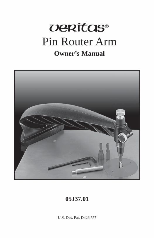
Pin Router ArmOwner’s Manual
05J37.01
U.S. Des. Pat. D426,557

2
Pin Router Arm 05J37.01
SAFETY RULES ...........................................................................................4
INTRODUCTION ..........................................................................................6
SET-UP ............................................................................................................. 7
ASSEMBLY ....................................................................................................7
INSTALLATION ..............................................................................................9
GENERAL USE ..........................................................................................11
COPY WORK ..............................................................................................14
TEMPLATES ................................................................................................14
INLAY WORK .............................................................................................. 16
CREATING FITTED CAVITIES ....................................................................18
TROUBLESHOOTING .................................................................................19
SIGN WORK .................................................................................................20
REVERSED IMAGES ..................................................................................21
MOUNTING TO OTHER ROUTER TABLES ............................... 22
VERITAS® ROUTER BIT JACK .......................................................... 23
3

These safety instructions are meant to complement those that came with your power tool. We suggest that you reread those, in addition to
those listed here before you begin to use this product. To use this product safely, always follow both sets of safety and general instructions.
Safety Rules
1. Read the manual. Learn the tool’s applications and limitations as well as the specifi c hazards related to the tool.
2. Use common sense. If an action appears to be unsafe, it likely is. 3. Wear eye protection. Everyday eyeglasses only have impact-resistant
lenses; they are not safety glasses. Also use a face or dust mask if the cutting operation is dusty. Visitors should also wear the same protection.
4. Wear hearing protection. 5. Wear proper apparel. Avoid wearing loose clothing, gloves, ties, rings
and bracelets as these can get caught in moving parts.6. Do not work under the infl uence of drugs, alcohol, or medication.
Drugs, alcohol, medication and lack of sleep cause impaired judgment and coordination and should not be combined with power tool operation.
7. Use in appropriate environment. Power tools should be used only in dry, clean and well-lit environments. Exposure to rain or use in the presence of fl ammable liquids or gases could result in damage or injury.
8. Keep workplace clean. Cluttered areas and benches invite accidents. 9. Practice proper maintenance. Keep all tools sharp, clean and well
lubricated for the best and safest results. Sharp bits, cutters and blades minimize stalling, kickback, and burning. They perform faster, better and safer than dull bits.
10. Keep safety guards in place and in working order.11. Do not use damaged tools. A damaged tool that does not operate
correctly is a safety hazard and should be fi xed before any further use. 12. Service the product properly. Use only identical replacement parts
when servicing. 13. Use the right tool. Don’t force a small tool or attachment to do the
job of a heavy-duty tool. 14. Don’t force tool. It will do the job better and safer at the rate for
which it was designed. 15. Use correct power supply. Never use a power source for which this
tool was not designed. It could cause serious injury. If the tool is equipped with a three-prong plug, it should be plugged into a three-hole electric receptacle. An adapter should be properly grounded.
4
16. Keep cord away from heat, oil and sharp edges. 17. Never carry tool by cord. 18. Do not carry plugged-in tool with fi nger on switch.19. Do not yank cord to disconnect from receptacle. 20. Unplug tool when changing bits. Always disconnect the tool from
the power source when changing bits, cutters or blades.21. Insert the shank or arbor of the bit (or mandrel or other accessory as
far as possible into the chuck (or collet). Then check to see if it has bottomed out, or if the radius in the corner where the shank meets the body is in contact with the chuck. In either case, raise the bit slightly to clear it so that the chuck can be tightened securely.
22. Remove adjusting keys and wrenches before use. 23. Keep hands away from moving parts. Hands and fi ngers should be
kept away from moving parts until they have come to a complete stop and the power has been disconnected.
24. Make sure the bit is not in contact with the workpiece before the power is turned on.
25. All external contours should be routed in a counterclockwise direction. All internal contours should be routed in a clockwise direction.
26. When raising a spinning router bit into a workpiece it is recommended to use the Veritas® Bit Jack as it allows you to control the workpiece with both hands. A foot pedal also allows you to raise and lower the bit as required.
27. Wait until the cutter attains full speed before cutting.28. Feed work into the cutter against the direction of cut.29. When working with a raised bit, carefully feed the workpiece into the
spinning bit until contact is made. 30. Hold the workpiece fi rmly against table. 31. When freehand pin routing, always hold the workpiece securely with
both hands. Move it fairly slowly, but without hesitation, to create as smooth a cut as possible. As with most freehand activities, a bit of practice does much to improve the end product.
32. Do not leave tool until it comes to a complete stop. 33. Store idle tools. When not in use, power tools should be stored in
a dry area, elevated and locked so that they are out of the reach of children.
34. Always ensure that there is a minimum of 1/8" between the top of the bit and the bottom of the guide pin. Even though the pins are made of aluminum, contact between spinning bit and pin should be avoided.
5
IntroductionThe Veritas® Pin Router Arm, when combined with the Veritas® Router Table (and most other router tables), allows a plunge router to be used as a pin router. The solid cast-aluminum arm rigidly holds the guide pin in place, while the clamping mechanism ensures secure attachment as well as easy installation and removal of the pin router arm.
Essentially, pin routing uses stationary pins to guide a template, which is attached to the workpiece to be routed. Because the rotating bit does not come into contact with the template, templates stay accurate and can be reused. Unlike conventional pin routers, the guide pin on the Veritas® Pin Router Arm is suspended from an overhead arm and a standard plunge router is mounted under a table. This inverted design makes it safer to operate, since the workpiece acts as a safety shield, keeping fi ngers away from the cutting area. The pin router arm also makes it easier to follow a template, since the guide pin is always in view. Pin routing goes further
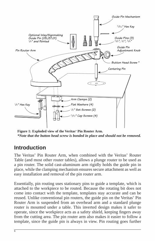
Figure 1: Exploded view of the Veritas® Pin Router Arm.*Note that the button head screw is bonded in place and should not be removed.
Pin Router Arm
1/4" Hex Key
Optional Inlay/SignmakingGuide Pin (05J37.01)1/4" and Pointed
Guide Pin Mechanism
3/32" Hex Key
Guide Pins (3)3/8", 1/2", 3/4"
Guide Pin Adjustment Knob
Button Head Screw *
Centering Pin
Arm Clamps (2)
Flat Washers (4)1/2" Set Screws (2)
5/16" Cap Screws (4)
6

than just making it easy to copy items; it also simplifi es the process of making templates, inlaying work and making relief or incised signs.
Full benefi t of the pin router arm can be achieved when it is used in conjunction with the Veritas® Bit Jack (see page 23 for more information). The pin router arm can be used without the bit jack for external template routing; however, because of the diffi culty in raising a rotating bit into a workpiece, attempting internal contours without the bit jack is not recommended.
The arm provides at least 12" of clearance to the router bit. This means that you can rout contours to the center of a 2' diameter workpiece.
As with any power tool accessory, you should read all instructions fi rst to be sure that you get the most from the tool while operating it safely. You should familiarize yourself with all associated equipment before learning to use the pin router arm.
Set-Up
Assembly
As delivered, the Veritas® Pin Router Arm requires some assembly.
1. Use the included 1/4" hex key to install one 1/2" set screw in each arm clamp so that they are flush (Figure 2).
Figure 2: Installing set screws in arm clamp.
Arm Clamp
1/2" Set Screw
1/4" Hex Key
7
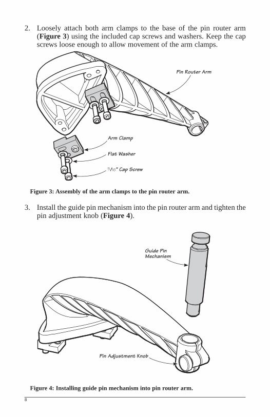
2. Loosely attach both arm clamps to the base of the pin router arm (Figure 3) using the included cap screws and washers. Keep the cap screws loose enough to allow movement of the arm clamps.
Figure 3: Assembly of the arm clamps to the pin router arm.
3. Install the guide pin mechanism into the pin router arm and tighten the pin adjustment knob (Figure 4).
Figure 4: Installing guide pin mechanism into pin router arm.
Arm Clamp
Flat Washer
5/16" Cap Screw
Pin Router Arm
Guide PinMechanism
Pin Adjustment Knob
8

Installation
The following procedure is for installing the Veritas® Pin Router Arm to the Veritas® Router Table. For installing the arm to other tables, see Mounting to Other Router Tables.
1. Install the centering pin in your router, with the drilled end exposed. The centering pin has a stepped shaft to accommodate either a 1/4" or a 1/2" collet.
2. Raise the router such that the centering pin projects through the router table (Figure 5).
Figure 5: Placing centering pin in router collet.
3. Install the 3/8" guide pin into the guide pin mechanism using the 3/32" hex key (Figure 6). Ensure that it is fully seated before tightening the set screw.
Figure 6: Installing 3/8" guide pin.
Centering Pin(hole up)
3/32" Hex Key
3/8" Guide Pin
9

4. Place the pin router arm on the uppermost left-hand corner of the router table, as shown in Figure 7, with the guide pin in the hole of the centering pin. Ensure that the arm sits fl at on its base. (You may have to raise or lower either the guide pin or the router.)
Figure 7: Installing pin router arm on centering pin. Note: side of router table with the shortest distance between router and table edge is to the front.
Note: The Veritas® Router Table Top is manufactured with a slight crown so that it will not sag under the weight of the router. This ensures that the area of your workpiece that is in contact with the bit is always constant and predictable. A side result of this crown is that the pin router arm may be angled slightly upward when installed, leaving the axis of the bit and the guide pin at a very slight angle to each other. This may cause some binding between centering pin and guide pin during set-up, but will not affect the accuracy of the tool, as the points of intersection between the bit and guide pin will remain concentric.
5. Adjust each arm clamp so that the edge of the rebated corner is butted against the edge of the router table. Tighten the cap screws securely in place using the 1/4" hex key (Figure 8).
Figure 8: Securing the arm clamps.
6. Tighten the 1/2" set screws using the 1/4" hex key. Note that the set screws do not have to be extremely tight to prevent the arm from moving in use and to keep it secured to the table top. The set screw tips will leave a small impression in the bottom of the router table. This will help with registration on subsequent installations.
Centering PinShor
t Sid
e
Set Screw
Arm Clamp
Cap Screw
1/4" Hex Key
10

7. Raise and lower the guide pin or router centering pin to verify that the two are perfectly concentric. Readjust the arm if this is not the case.
After this initial set-up, it should now be possible to remove the pin router arm by simply loosening the set screws, and to replace it in the exact same location without requiring the use of the centering pin (providing the router is not removed from the router table in the interim). However, we recommend that you use the centering pin for the fi rst few installations before you consider dispensing with this step.
General Use
1. Install the appropriate sized router bit and matching guide pin. The supplied guide pins are 3/8", 1/2" and 3/4" in diameter. An optional 1/4" guide pin (05J37.10) is available separately. For most work, you will want to use a compatibly sized bit. Depending on the shape of the piece to be copied, you may want to use a fairly small guide pin/bit diameter in order to get as much detail as possible (because inside corners are limited by the guide pin/bit radius).
2. Set the router or bit jack to give the desired depth of cut. To rout through a workpiece, your bit should be set slightly higher than the top surface of your workpiece. For pocket routing, your bit should be set to your desired depth.
3. If it is not already so, turn the knob on the top of the guide pin mechanism so that the pin is free to spring to its lowered position (Figure 9). Loosen the guide pin adjustment knob and set the pin position. While the arm itself is very stiff, the router table has some flexibility.
Always ensure that there is a minimum
of 1/8" between the top of the bit and the bottom of the guide pin. Even though the pins are made of aluminum, contact between spinning bit and pin should be avoided!
Figure 9: Ensure minimum 1/8" clearance between top of bit and bottom of guide pin.
1/8" Min.
Guide Pinin lowered position
Router Bitin raised position
11
Once the bit height and pin position have been set, you are ready to use the pin router arm.
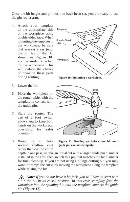
4. Attach your template to the appropriate side of the workpiece using double-sided tape. When mounting the template to the workpiece, be sure that weaker areas (e.g., the thin leg on the "A" shown in Figure 10) are securely attached to the workpiece. This will reduce the chance of breaking these parts during routing.
5. Lower the bit.
6. Place the workpiece on the router table, with the template in contact with the guide pin.
7. Start the router. The use of a foot switch allows you to keep both hands on the workpiece, providing for safer operation.
8. Raise the bit. Take several shallow cuts rather than cut the entire depth in one pass, or take an initial cut with a larger guide pin diameter installed in the arm, then switch to a pin that matches the bit diameter for final clean-up. If you are not using a plunge-cutting bit, you may want to "ramp" the cut in by moving the workpiece along the template while raising the bit.
Note: If you do not have a bit jack, you will have to start with the bit in its raised position. In this case, carefully feed the
workpiece into the spinning bit until the template contacts the guide pin (Figure 11).
Figure 11: Feeding workpiece into bit until guide pin contacts template.
Template
Double-SidedTape
Workpiece
12
Figure 10: Mounting a workpiece.
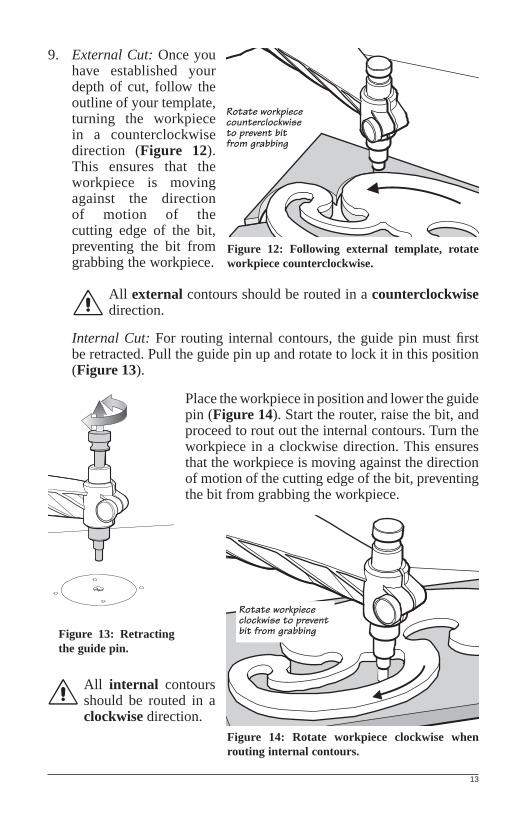
9. External Cut: Once you have established your depth of cut, follow the outline of your template, turning the workpiece in a counterclockwise direction (Figure 12). This ensures that the workpiece is moving against the direction of motion of the cutting edge of the bit, preventing the bit from grabbing the workpiece.
All external contours should be routed in a counterclockwise direction.
Internal Cut: For routing internal contours, the guide pin must fi rst be retracted. Pull the guide pin up and rotate to lock it in this position (Figure 13).
Place the workpiece in position and lower the guide pin (Figure 14). Start the router, raise the bit, and proceed to rout out the internal contours. Turn the workpiece in a clockwise direction. This ensures that the workpiece is moving against the direction of motion of the cutting edge of the bit, preventing the bit from grabbing the workpiece.
All internal contours should be routed in a clockwise direction.
Rotate workpiece counterclockwise to prevent bitfrom grabbing
Rotate workpiece clockwise to prevent bit from grabbing
13
Figure 12: Following external template, rotate workpiece counterclockwise.
Figure 13: Retracting the guide pin.
Figure 14: Rotate workpiece clockwise when routing internal contours.

Copy Work
Often it is desirable to copy an odd-shaped piece for repair work or to copy a design for repeated decorative accents. You may use the original piece as your template. Mount it to a spacer to ensure that it will not come in contact with the bit (Figure 15). If you are going to make several copies of an original, you may want to fi rst use the pin router to create a template (see Templates) from some durable material in order to preserve the original from possible damage.
Figure 15: Copying.
Templates
Almost any suitable original can be used as a template. Even delicate or valuable items can be used as they can be offset from the workpiece such that there is no danger of the bit contacting them (see Copy Work). Items such as drawing templates can also be used.
Templates may be made from plywood or masonite, and cut to shape using a scrollsaw or a bandsaw. The template should be from 1/4" to 1/2" thick to ensure good contact with the guide pin. Usually, the template contour should be exactly what you want to achieve; no offsetting is required (as would be with guide bushing templates). There are some cases, such as inlay routing (see page 16), where an offset template is required. Drawing the shape on paper fi rst, then sticking it to the template material will help you cut the shape precisely.
Template edges and contours should be fairly smooth. Because the pin router arm will make an accurate copy of the template, any bumps or dents on your template will show up on your workpiece.
3/8" Guide Pin
3/8" Router Bit
Part to be copied
Spacer
Copied workpiece
14

If you already have a number of templates created for guide bushing routing (with their associated offset), you can use these with the pin router arm. All you have to do is respect the original size difference between bit and bushing when you convert the bit and pin method. For example, if the template was created to use a 3/4" guide bushing and a 5/8" bit, use the 3/4" guide pin in the pin router arm and 5/8" bit in your router.
If you are going to be routing the workpiece face up, such as when routing completely through the workpiece, you should place the template so that you see the design as you want it to be. However, there are times when templates must be mounted to the back of your workpiece, such as when surface routing letters for a sign. This means that you will be looking at a template that is the mirror image of what you want (Figure 16).
Figure 16: For routing into the face of a workpiece, the template must be reversed.
If you are routing with the workpiece face down, you should place the template so that you see a mirror image of what you want (i.e., place the template face down as well).
Mounting the template to the workpiece can be done in a number of ways; however, for most jobs double-sided tape is suffi cient. If you are going to be doing a lot of repetitive work, you may consider buying or building a vacuum fi xture. These are described in a number of router books.
Pattern cut into front face of workpiece.
Pattern cut through template. Template mounted
to back face of workpiece.
15

Inlay Work
With the optional Inlay/Signmaking guide pin (05J37.10), the Veritas® Pin Router Arm makes inlay routing as easy as 1-2-3. We do, however, suggest that you experiment on some scrap workpieces to become familiar with the procedure and check your set-up.
1. Make a template. This template will act as your internal guide. It should be a female of the shape you will be inlaying, and have a contour that is offset 1/4" larger than the final inlay size since the 1/4" bit used to follow the internal shape of the template will leave the inside routed section smaller all around (Figure 17).
Figure 17: Typical template, note offset from desired shape.
Templates with fl oating sections (e.g., the center of the letter "A") will need to be mounted on a backing piece to hold the parts in position (Figure 18). Equally important, the backing piece should be at least 3/8" thick so that through cuts can be made to inlaying material later.
Figure 18: Template with floating section.
1/4" Offset fromdesired inlay shape
Template
Inlay
05J37.10
1/4"
Floating Section
Template
Backing Piece
16

If you already have a number of templates created for guide bushing routing (with their associated offset), you can use these with the pin router arm. All you have to do is respect the original size difference between bit and bushing.
Almost any suitable original can be used as a template. Even delicate or valuable items can be used as they can be offset from the workpiece such that there is no danger of the bit contacting them (see Creating Fitted Cavities). Items such as drawing templates can also be used.
2. Cut cavity. Secure the template to the back of the workpiece that is to receive the inlay. Use the 3/4" guide pin and a 1/4" bit. Set the bit height for the depth of the cavity to slightly less than the thickness of your inlay to leave a sanding allowance to bring the two pieces perfectly flush. Adjust the guide pin so that it is slightly above the workpiece (or backing piece if used). Rout the perimeter of the workpiece cavity (turning the workpiece clockwise) before removing any internal waste (Figure 19).
3. Cut insert/inlay piece. When cutting the inlay, both the inlay material and the template must be attached to a dividing spacer to keep pieces from floating around freely after cutting. After sandwiching the three pieces, replace the 3/4" guide pin with the optional inlay/signmaking guide pin (05J37.10), with the 1/4" end exposed. Set the bit height so that it cuts through the inlay material but not through the spacer material (Figure 20). Rout the inlay in a clockwise direction and remove Figure 20: Cutting the inlay.
Figure 19: Cutting the cavity.
3/4" Guide Pin
1/4" Guide PinTemplate
Backer
1/4" Router BitInlay
Cavity1/4" Router Bit
Workpiece
Template
17

it from the spacer material. Carefully sand edges to remove any whiskers (but not round the edge) and you will have a piece that fi ts perfectly in the cavity.
Note: Keep in mind that no corner radius can be less than 3/8".
Notes on obtaining perfect inlays: It is vital that the guide pins be exactly concentric with the bit. Take extra care when installing the pin router arm. The router bit must cut exactly 1/4" in diameter. A bit cutting oversize will result in loose inlays, while an undersize bit will result in oversize inlays. When cutting the inlay piece, ensure that the pin is always in contact with the template; losing contact with the template will cause unsightly undercuts in the inlay. If you still do not obtain perfect fi tting inlays, see Troubleshooting.
Creating Fitted Cavities
The pin router arm can also be used to fi t an odd-shaped piece of hardware or existing inlay into a cavity, using a variation of the procedure above. Mount the part you want to inlay onto the back of a piece of 1/2" to 3/4" thick material. Because this piece will become the template for future work, you may want to use hardwood or plywood. Remember the same limitation exists here as when making your own inlay; no corner radius can be less than 3/8". If your original has fairly thin edges, you may want to use a spacer in order to ensure the guide pin has good contact with the part (Figure 21a).
Figure 21a: Making a template from an original part to be inlaid.
Use the 1/4" guide pin and 1/4" bit to cut the required cavity in the template material. The depth of the template cavity should be at least 1/4", but not through; otherwise, the part being traced will come free. This will make a template that is 1/4" offset from the original part. As was explained in
1/4" Guide Pin
Template
1/4" Router Bit
Part to be inset.
Spacer
1/4" Minimum
18

Step 2, Cut Cavity, with the 3/4" guide pin and 1/4" bit installed, use the template you just created to cut the cavity for the original part. The original part should fi t snugly (Figure 21b).
Figure 21b: Using template to cut cavity for inlaid part.
Troubleshooting
Even following the preceding instructions may not result in exactly the results you want. This can be due to a number of reasons, including bits that are not exactly the same size as the guide pins or slightly off center installation of the arm. Careful set-up and creating test pieces are your best protection.
The following suggestions may help resolve some problems you may encounter.
1. Cavity too large (inlay too small). Wrap a layer of tape around the 3/4" guide pin before cutting the cavity. This will increase the offset between the template and the cavity, making the cavity smaller by the thickness of the tape. Avoid overlapping the tape on the pin.
2. Cavity too small (inlay too big). Wrap a layer of tape around the 1/4" guide pin before cutting the inlay. This will increase the offset between the template and the inlay, making the inlay smaller by the thickness of the tape. Again, avoid overlapping the tape on the pin.
3. Corners don’t match. This is likely due to a template corner radius that is smaller than 3/8".
4. Gaps between inlay and cavity. Likely, the pin was not in contact with the template at some point while cutting the inlay. You might also want to check for bumps in the profile of the template.
Template
Workpiece
3/4" Guide Pin
Cavity1/4" Router Bit
19

Sign Work
A pin router shines in signmaking since it is generally easier to move the workpiece than the router. Freehand "one-offs" can be routed or more structured templates can be used for repetitive work.
For a "one-off", you’ll need a mirror image of your sign design. See Reversed Images for how this is easily done. Attach your design to the back of your workpiece. Install an engraving bit of your choice in your router and adjust it to the depth of cut you need. Install the optional pointed signmaking guide pin (05J37.10) into the pin router arm. Adjust the pin height so that it is very nearly touching the workpiece (move the workpiece around to ensure the pin won’t jam against it).
Turn the router on and raise the bit into the workpiece, holding the workpiece with both hands. Move the workpiece slowly to create as smooth a cut as possible.
Figure 22: Freehand signmaking.
Note: It is possible to raise a spinning bit into a workpiece without a bit jack, but we don’t recommend it. With a bit jack, it is a piece of cake. You control the workpiece with both hands and use a foot
pedal to raise and lower the bit as required, letting you move from one letter to another without removing either hand from your work.
Tip & Safety Note: Remember that there is nothing but your own strength resisting the cutting forces when freehand pin routing, and these can be in unpredictable directions. Always hold the workpiece
securely with both hands, moving it fairly slowly, but without hesitation, to create as smooth a cut as possible. As with most freehand activities, a bit of practice does much to improve the end product. We suggest you develop this on some practice signs, fi rst in a clear soft wood such a knot-free poplar, cedar or pine.
20

Trace along the lines and clean up the internal cavity to achieve incised lettering; trace outside the lines and remove external waste to achieve relief (or raised) lettering. Waste areas can either be routed off free hand or later removed with a small hand plane or chisel.
Figure 23: Relief lettering.
If you intend to create several copies of the same design, the process is changed. The fi rst difference is that you’ll need to make a mirror-image template from 1/2" to 3/4" thick hardwood or plywood. Create your artwork as you want it to be (no mirror image) and attach it (right-side up) to the back of your template material. Use a 1/4" bit to rout the template to a depth of 1/8". Note that the result is a mirror track of the sign you want. Switch the signmaking guide pin end for end, leaving the 1/4" pin end exposed to match the bit size used to cut the template. Change the bit to an engraving bit of your choice. Attach your workpiece to the template. Engage the pin in the groove in the template and rout away, lowering the bit before disengaging the pin between letters.
Reversed Images
Making a mirror image is a simple matter with the help of modern technology. You can photocopy your image on clear acetate or use a hot iron to transfer the toner from a photocopy (ink side down!) onto another piece of paper. The toner in photocopiers is thermoplastic, meaning that it will melt with heat. Another way to create a mirror image is to design your sign on a computer and use the "fl ip horizontal" feature. A computer-generated design also eliminates the headaches of laying out the text, giving you more time to spend in the shop than at the drawing board.
Waste area removedby freehand routing.
Engraved outlineof letters.
Outer edge left tokeep workpiece stableduring routing.
21

Mounting to Other Router Tables
The Veritas® Pin Router Arm is designed to be mounted from the corner of the Veritas® Router Table. It is nevertheless possible to mount it to other tables; however, this may require some modifi cation of the table. Also, the ability to quickly remove the arm may be compromised.
If your table dimensions happen to match those shown in Figure 24, you may be able to mount the pin router arm as described earlier.
Figure 24: Dimensions of Veritas® Router Table.
If not, you will have to modify your table to accommodate the arm clamps. Drill 3/8" holes through the table as indicated in Figure 25. The locations for these holes are with respect to the bit center.
Figure 25: Mounting hole dimensions.
24"
12"
Pin Router Armmounted to thiscorner of the table
Router bit axis
9 3/8"
16"
3/4" 8 5/8"
Pin Router Armmounting holes3/8" diameter
3/4"
5 1/4"
12 1/2"
9 7/8"
Router bit axis
22

Veritas® Router Bit Jack, 05J24.20, .21, .22, & .40
(No longer available.)
Sign and inlay routing can be best achieved when the pin router arm is used in conjunction with the Veritas® Router Bit Jack. The bit jack opens up a third dimension (vertical) to the router table system by being able to raise a plunge router by actuating either a lever or a foot pedal. This allows you to safely raise the bit into your workpiece, take a controlled cut, and lower the bit at the end of the cut, leaving your hands free to control your work. Because of the diffi culty in raising a rotating bit into a workpiece, attempting internal contours without the bit jack is not recommended.
Figure 26: Pin router arm mounted with bit jack.
The bit jack has two further advantages for inlay routing. It makes accurate bit height adjustment easy and allows you to take progressive cuts without resetting fi nal cut height.
A ball detent micro-adjust mechanism allows for fi ne vertical adjustments. You don’t have to peer under the router table to check anything; each click of the knob raises or lowers the bit in 0.002" increments. A shop-made foot pedal simplifi es the process of making repeated passes at different heights without delay or adjustment.
23

Contact your Veritas® dealer for information on other Veritas® Router Table accessories.
814 Proctor AvenueOgdensburg, New York
13669-2205 USA
1090 Morrison DriveOttawa, OntarioK2H 1C2 Canada
426© Veritas Tools Inc. 2011
INS-140 Rev. CPrinted in Canada
![retromodelisme.com · 2007. 10. 28. · RACER Parts GALLOP in the 4WDS bags Q'ty Part Used in Instruction 6] 5] 8] 19] Front Upper Sus. Arm Pin Front Rower Sus. Arm Pin Front Damper](https://static.fdocuments.us/doc/165x107/6112586b515f21565a302d39/2007-10-28-racer-parts-gallop-in-the-4wds-bags-qty-part-used-in-instruction.jpg)