
Pin Cylinder: Single Acting, Spring Return
10
Ejector Application Examples A short-stroke miniature cylinder with a shorter overall length The installation space can be significantly reduced because this cylinder can be recessed directly into a machine or installed on a panel. Thus, the machine can be made more compact. Rod end cap can now be ordered with the cylinder. Applicable for the change of the rod end shape (-XAm) (Simple Specials) R p. 6 One-touch fitting can be connected. (Panel mount type) 16 mm bore size is now available. (Changed from the existing product: 15 mm) It is not necessary to order a rod end cap for the applicable cylinder separately. ø2 One-touch fitting, miniature fitting, and speed controller can be connected. Specifications and dimensions are the same as the existing product. ø2 One-touch fitting Clamper CJPS16 15Z T Example Rod end cap Nil Without cap T Rod end cap (Flat type) U Rod end cap (Round type) Gripper Stopper Actual size RoHS CAT.ES20-265A CJP Series Pin Cylinder: Single Acting, Spring Return ø4, ø6, ø10, ø16
Transcript of Pin Cylinder: Single Acting, Spring Return
Ejector
Application Examples
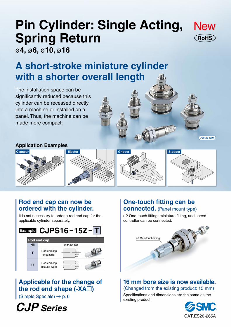
A short-stroke miniature cylinder with a shorter overall lengthThe installation space can be significantly reduced because this cylinder can be recessed directly into a machine or installed on a panel. Thus, the machine can be made more compact.
Rod end cap can now be ordered with the cylinder.
Applicable for the change of the rod end shape (-XAm)
(Simple Specials) R p. 6
One-touch fitting can be connected. (Panel mount type)
16 mm bore size is now available.(Changed from the existing product: 15 mm)
It is not necessary to order a rod end cap for the applicable cylinder separately.
ø2 One-touch fitting, miniature fitting, and speed controller can be connected.
Specifications and dimensions are the same as the existing product.
ø2 One-touch fitting
Clamper
CJPS16 15Z TExample
Rod end capNil Without cap
TRod end cap
(Flat type)
URod end cap (Round type)
Gripper Stopper
Actual size
RoHS
CAT.ES20-265A
CJP Series
Pin Cylinder: Single Acting, Spring Returnø4, ø6, ø10, ø16
MoistureControl TubeIDK Series
Pin Cylinder: Single Acting, Spring Return
ø4, ø6, ø10, ø16CJP Series
Embedded typePanel mount type
Made to Order (ø6 to ø16)(For details, refer to pages 6 and 7.)
SpecificationsSymbolSingle acting, Spring return
∗1 When rod end is threaded∗ For details about the hose nipple (accessory), refer to page 8.
Symbol Specifications
XAm Change of rod end shape
XC17 Pin cylinder with rod quenched
XC22 Fluororubber seals
B 15CJP
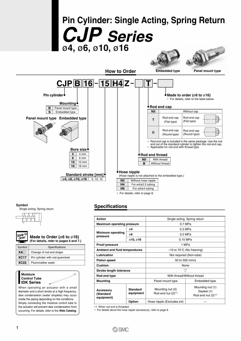
How to Order
Pin cylinder
16 H4 Z T
MountingB Panel mount type
S Embedded type
Bore size4 4 mm
6 6 mm
10 10 mm
16 16 mm
Standard stroke [mm]ø4, ø6, ø10, ø16 5, 10, 15
Rod end threadNil With thread
B Without thread
∗ For details, refer to the table below.Made to order (ø6 to ø16)
Hose nipple(Hose nipple is not attached to the embedded type.)
Nil Without hose nipple
H4 For ø4/ø2.5 tubing
H6 For ø6/ø4 tubing
∗ For details, refer to page 8.
Rod end capNil Without cap
TRod end cap
(Flat type)Rod end cap (Flat type)
URod end cap (Round type)
Rod end cap (Round type)
∗ Rod end cap is included in the same package. Use the rod end nut of the standard cylinder to tighten the rod end cap.
∗ Applicable for rod end with thread type
Embedded type Panel mount type
Action Single acting, Spring return
Maximum operating pressure 0.7 MPa
Minimum operating pressure
ø4 0.3 MPa
ø6 0.2 MPa
ø10, ø16 0.15 MPa
Proof pressure 1 MPa
Ambient and fluid temperatures –10 to 70°C (No freezing)
Lubrication Not required (Non-lube)
Piston speed 50 to 500 mm/s
Cushion None
Stroke length tolerance +1.0 0
Rod end type With thread/Without thread
Mounting Panel mount type Embedded type
Accessory(Standard equipment)
Standard equipment
Mounting nut (2)Rod end nut (2)∗1
Mounting nut (1)Gasket (1)
Rod end nut (2)∗1
Option Hose nipple (Excludes ø4) —
When operating an actuator with a small diameter and a short stroke at a high frequency, dew condensation (water droplets) may occur inside the piping depending on the conditions.Simply connecting the moisture control tube to the actuator will prevent dew condensation from occurring. For details, refer to the Web Catalog.
1
Pin Cylinder: Single Acting, Spring Return CJP Series
[N]
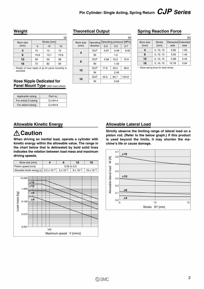
∗ Weight of hose nipple (4 g) for panel mounting is excluded.
[N]
∗ Same spring force for each stroke
[g]
Spring Reaction Force
Hose Nipple Dedicated for Panel Mount Type (With fixed orifice)
Weight Theoretical Output
Bore size[mm]
Stroke [mm]
5 10 15
4 10 13 15
6 10.6 13.1 15.6
10 28 33 38
16 72 82 92
Bore size[mm]
Operatingdirection
Operating pressure [MPa]
0.3 0.5 0.7
4OUT 0.97 3.48 6.00
IN 1.0
6OUT 4.56 10.2 15.9
IN 1.42
10OUT 17.6 33.3 49.0
IN 2.45
16OUT 44.5 84.7 124.9
IN 5.04
Applicable tubing Part no.
For ø4/ø2.5 tubing CJ-5H-4
For ø6/ø4 tubing CJ-5H-6
Bore size[mm]
Stroke[mm]
Retracted side
Extended side
4 5, 10, 15 2.80 1.00
6 5, 10, 15 3.92 1.42
10 5, 10, 15 5.98 2.45
16 5, 10, 15 15.78 5.04
When driving an inertial load, operate a cylinder with kinetic energy within the allowable value. The range in the chart below that is delineated by bold solid lines indicates the relation between load mass and maximum driving speeds.
Caution
Allowable Kinetic Energy
0.001100
Maximum speed V [mm/s]
0.010
0.100
1.000
10.000
Load
mas
s [k
g]
ø4
ø16ø10
ø6
Bore size [mm] 4 6 10 16Piston speed [m/s] 0.05 to 0.5
Allowable kinetic energy [J] 0.5 x 10⁻³ 3 x 10⁻³ 8 x 10⁻³ 19 x 10–3
Strictly observe the limiting range of lateral load on a piston rod. (Refer to the below graph.) If this product is used beyond the limits, it may shorten the ma-chine’s life or cause damage.
Allowable Lateral Load
Stroke ST [mm]
Allo
wab
le la
tera
l loa
d W
[N]
0.0
0.1
0.2
0.3
0.4
0.5
0.6
0.7
10 155
ø4
ø6
ø16
ø10
2
oieu qyr w t
CJP Series
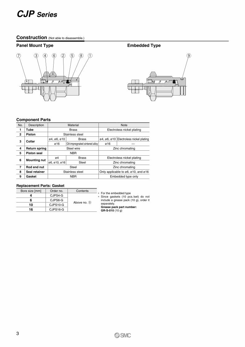
Construction (Not able to disassemble.)
Panel Mount Type Embedded Type
Component Parts
∗ For the embedded type∗ Since gaskets (10 pcs./set) do not
include a grease pack (10 g), order it separately.Grease pack part number: GR-S-010 (10 g)
Replacement Parts: GasketBore size [mm] Order no. Contents
4 CJPS4-G
Above no. o6 CJPS6-G
10 CJPS10-G
16 CJPS16-G
No. Description Material Note
1 Tube Brass Electroless nickel plating
2 Piston Stainless steel
3 Collarø4, ø6, ø10 Brass ø4, ø6, ø10 Electroless nickel plating
ø16 Oil-impregnated sintered alloy ø16 —
4 Return spring Steel wire Zinc chromating
5 Piston seal NBR
6 Mounting nutø4 Brass Electroless nickel plating
ø6, ø10, ø16 Steel Zinc chromating
7 Rod end nut Steel Zinc chromating
8 Seal retainer Stainless steel Only applicable to ø6, ø10, and ø16
9 Gasket NBR Embedded type only
3
øQ
C0.3
10
11.5
ZS
F6
7.5
7 7 B
C
ZS
F EAH
13 (12)
R
H7.5
3
C0.3
MM
W
NN ø
G
(Hose nipple)Mounting dimensions of CJ-5H-6. ( ) denotes the dimensions of CJ-5H-4.
Without rod end threadCJPB4-�-B
Without rod end threadCJPB�-�-B
10
11.5
ZS
6
7.5
6
7 7 B
C
Z
A EøG
d9
RH7.5
3 W K
NN
MM
ø2
øQ
Without rod end threadCJPS4-�-B
Without rod end threadCJPS�-�-B
FF
SH
Exhaust port
M2
x 0.
4
M8
x 1
ø6.
5
3
ø2
Exhaust port
ø8.
5 (ø
6.5)
M5
x 0.
8
ø6: C0.5ø10, ø16: C1
Exhaust port
ø0.
8
ø6: C0.5ø10, ø16: C1
Exhaust port M8
x 1
ø6.
5 m
ax.
ø0.
4
3.5M2
x 0.
4
Pin Cylinder: Single Acting, Spring Return CJP Series
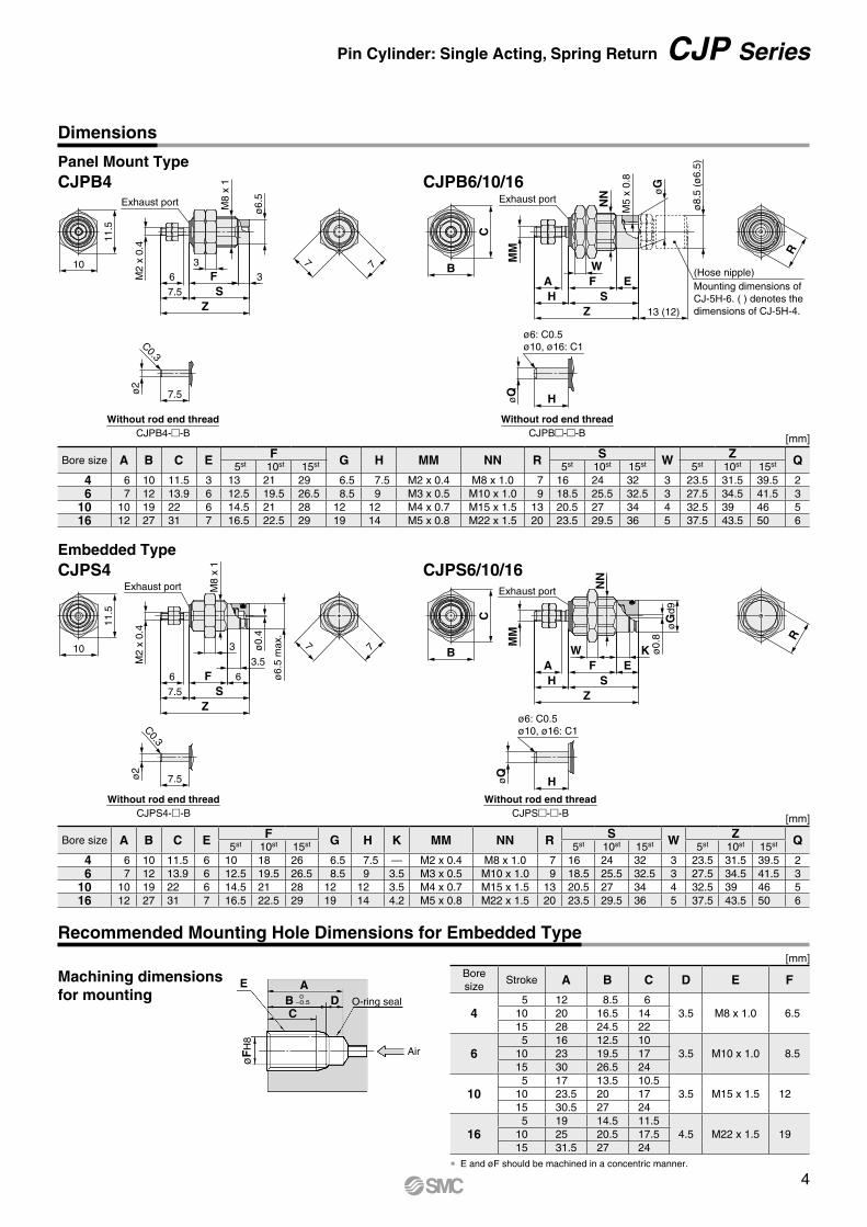
Recommended Mounting Hole Dimensions for Embedded Type
Panel Mount Type
Embedded Type
CJPB4
CJPS4
CJPB6/10/16
CJPS6/10/16
∗ E and øF should be machined in a concentric manner.
[mm]
[mm]
[mm]
Air
E A
C
øF
H8
B D 0−0.5 O-ring seal
Dimensions
Bore size A B C E F G H K MM NN R S W Z Q5st 10st 15st 5st 10st 15st 5st 10st 15st
4 6 10 11.5 6 10 18 26 6.5 7.5 — M2 x 0.4 M8 x 1.0 7 16 24 32 3 23.5 31.5 39.5 26 7 12 13.9 6 12.5 19.5 26.5 8.5 9 3.5 M3 x 0.5 M10 x 1.0 9 18.5 25.5 32.5 3 27.5 34.5 41.5 3
10 10 19 22 6 14.5 21 28 12 12 3.5 M4 x 0.7 M15 x 1.5 13 20.5 27 34 4 32.5 39 46 516 12 27 31 7 16.5 22.5 29 19 14 4.2 M5 x 0.8 M22 x 1.5 20 23.5 29.5 36 5 37.5 43.5 50 6
Bore size A B C E F G H MM NN R S W Z Q5st 10st 15st 5st 10st 15st 5st 10st 15st
4 6 10 11.5 3 13 21 29 6.5 7.5 M2 x 0.4 M8 x 1.0 7 16 24 32 3 23.5 31.5 39.5 26 7 12 13.9 6 12.5 19.5 26.5 8.5 9 M3 x 0.5 M10 x 1.0 9 18.5 25.5 32.5 3 27.5 34.5 41.5 3
10 10 19 22 6 14.5 21 28 12 12 M4 x 0.7 M15 x 1.5 13 20.5 27 34 4 32.5 39 46 516 12 27 31 7 16.5 22.5 29 19 14 M5 x 0.8 M22 x 1.5 20 23.5 29.5 36 5 37.5 43.5 50 6
Bore size
Stroke A B C D E F
45 12 8.5 6
3.5 M8 x 1.0 6.510 20 16.5 1415 28 24.5 22
65 16 12.5 10
3.5 M10 x 1.0 8.510 23 19.5 1715 30 26.5 24
105 17 13.5 10.5
3.5 M15 x 1.5 1210 23.5 20 1715 30.5 27 24
165 19 14.5 11.5
4.5 M22 x 1.5 1910 25 20.5 17.515 31.5 27 24
Machining dimensions for mounting
4
L
N
øD
MMA
C0.5
W
RR
MM
øD
N
L
A
W
B
d
C
H B
C
H
d
Material: Polyacetal [mm]
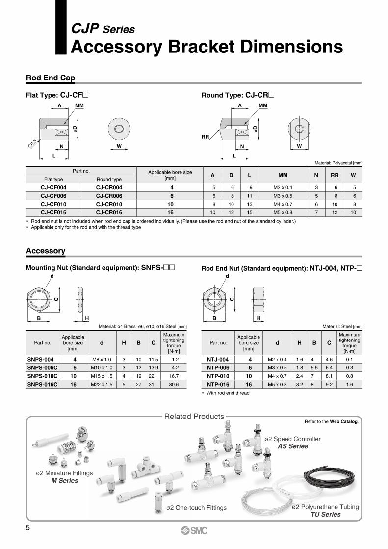
Rod End Cap
Accessory
Flat Type: CJ-CFm Round Type: CJ-CRm
Part no. Applicable bore size[mm] A D L MM N RR W
Flat type Round type
CJ-CF004 CJ-CR004 4 5 6 9 M2 x 0.4 3 6 5
CJ-CF006 CJ-CR006 6 6 8 11 M3 x 0.5 5 8 6
CJ-CF010 CJ-CR010 10 8 10 13 M4 x 0.7 6 10 8
CJ-CF016 CJ-CR016 16 10 12 15 M5 x 0.8 7 12 10
Mounting Nut (Standard equipment): SNPS-mm Rod End Nut (Standard equipment): NTJ-004, NTP-m
Material: ø4 Brass ø6, ø10, ø16 Steel [mm] Material: Steel [mm]
∗ Rod end nut is not included when rod end cap is ordered individually. (Please use the rod end nut of the standard cylinder.)∗ Applicable only for the rod end with the thread type
∗ With rod end thread
Part no.Applicable bore size
[mm]d H B C
Maximum tightening
torque[N·m]
SNPS-004 4 M8 x 1.0 3 10 11.5 1.2
SNPS-006C 6 M10 x 1.0 3 12 13.9 4.2
SNPS-010C 10 M15 x 1.5 4 19 22 16.7
SNPS-016C 16 M22 x 1.5 5 27 31 30.6
Part no.Applicable bore size
[mm]d H B C
Maximum tightening
torque[N·m]
NTJ-004 4 M2 x 0.4 1.6 4 4.6 0.1
NTP-006 6 M3 x 0.5 1.8 5.5 6.4 0.3
NTP-010 10 M4 x 0.7 2.4 7 8.1 0.8
NTP-016 16 M5 x 0.8 3.2 8 9.2 1.6
ø2 Miniature FittingsM Series
Related Products
ø2 Polyurethane TubingTU Series
ø2 Speed ControllerAS Series
Refer to the Web Catalog.
ø2 One-touch Fittings
5
CJP Series
Accessory Bracket Dimensions
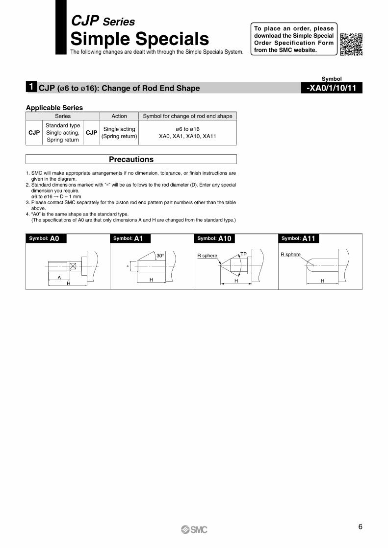
1. SMC will make appropriate arrangements if no dimension, tolerance, or finish instructions are given in the diagram.
2. Standard dimensions marked with “∗” will be as follows to the rod diameter (D). Enter any special dimension you require.ø6 to ø16 R D – 1 mm
3. Please contact SMC separately for the piston rod end pattern part numbers other than the table above.
4. “A0” is the same shape as the standard type. (The specifications of A0 are that only dimensions A and H are changed from the standard type.)
Precautions
Applicable Series
Symbol: A1Symbol: A0 Symbol: A10 Symbol: A11
Symbol
CJP (ø6 to ø16): Change of Rod End Shape1
AH
30°
∗
H
Series Action Symbol for change of rod end shape
CJPStandard typeSingle acting, Spring return
CJPSingle acting
(Spring return)ø6 to ø16
XA0, XA1, XA10, XA11
CJP Series
Simple SpecialsThe following changes are dealt with through the Simple Specials System.
TP
H
R sphere R sphere
H
-XA0/1/10/11
To place an order, please download the Simple Special Order Specification Form from the SMC website.
6
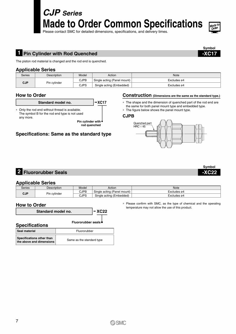
Construction (Dimensions are the same as the standard type.)
The piston rod material is changed and the rod end is quenched.
Applicable Series
XC17Standard model no.
Pin cylinder with rod quenched
∗ Only the rod end without thread is available. The symbol B for the rod end type is not used any more.
∗ The shape and the dimension of quenched part of the rod end are the same for both panel mount type and embedded type.
∗ The figure below shows the panel mount type.
How to Order
Specifications: Same as the standard type
CJPB
Symbol
-XC17Pin Cylinder with Rod Quenched1
Symbol
-XC22Fluororubber Seals2
Series Description Model Action Note
CJP Pin cylinderCJPB Single acting (Panel mount) Excludes ø4
CJPS Single acting (Embedded) Excludes ø4
CJP Series
Made to Order Common SpecificationsPlease contact SMC for detailed dimensions, specifications, and delivery times.
Applicable Series
XC22
Fluororubber seals
Standard model no.
How to Order
Specifications
∗ Please confirm with SMC, as the type of chemical and the operating temperature may not allow the use of this product.
Series Description Model Action Note
CJP Pin cylinderCJPB Single acting (Panel mount) Excludes ø4CJPS Single acting (Embedded) Excludes ø4
Seal material Fluororubber
Specifications other than the above and dimensions
Same as the standard type
Quenched partHRC ≈ 45
7

Piping
The following fittings are recommended for this cylinder connection. However, there may be a case where the piston speed exceeds 500 mm/s even with the recom-mended fittings for this cylinder. Use a speed controller in such cases.
∗ Please be aware that cylinder speed may slow down on the retracting side when using the above One-touch fittings and miniature fittings with a cylinder bore size of ø16.
Caution
∗ For details about One-touch fittings, miniature fittings and speed controllers (applicable tubing O.D. ø2 only), refer to the Web Catalog.Also, for details about speed controllers (applicable tubing O.D. ø3.2 to ø6), refer to the Web Catalog.
∗ Refer to the Fittings and Tubing Precautions (Web Catalog) for handling One-touch fittings.
In addition to the above fittings and hose nipples, the below fittings can also be attached to the cylinder.When using the below fittings, be sure to provide a speed controller after adjusting it to 500 mm/s or less.
Recommended Speed Controller
Hose nippleCJ-5H-4(For ø4/ø2.5 tubing)
CJ-5H-6(For ø6/ø4 tubing)
Mounting
Do not use it in such a way that a load could be applied to the piston rod during the retraction.The spring that is built into the cylinder provides only enough force to retract the piston rod. Thus, if a load is applied, the piston rod may not be able to retract to the end of the stroke.
Caution
Specific Product PrecautionsBe sure to read this before handling the products. Please consult with SMC for the use other than the specifications.
CJP Series
Cylinderbore size
Applicabletubing O.D.
Fitting typeConnection
threadModel
ø43.2
One-touch fitting
M3 x 0.5KQ2m23-M3G
4 KQ2m04-M3G
ø6ø10ø16
3.2
M5 x 0.8
KQ2m23-M5m4 KQ2m04-M5m6 KQ2m06-M5m
ø6.5
7
15.5
34
8.5
8
16.5
3
4
ø1.8 ø2.5
Width acrossflats 8
Width acrossflats 7
Gasket GasketM5 x 0.8 M5 x 0.8ø0.8ø0.8
Applicabletubing O.D. [mm]
Connectionthread
Elbow typemeter-in
Universal typemeter-in
In-line typemeter-in
ø2M3 AS1211F-M3-02 —
AS1002F-02M5 AS1211F-M5E-02A —
ø3.2M3 AS1211F-M3-23 AS1311F-M3-23
AS1002F-23M5 AS1211F-M5E-23A AS1311F-M5E-23A
ø4M3 AS1211F-M3-04 AS1311F-M3-04
AS1002F-04M5 AS1211F-M5E-04A AS1311F-M5E-04A
ø6 M5 AS1211F-M5E-06A AS1311F-M5E-06A AS1002F-06
Cylinderbore size
Applicabletubing O.D.
Fitting typeConnection
threadModel
ø4
ø2
One-touch fittingM3 x 0.5
KQ2m02-M3GMiniature fitting M-3AU-2
ø6ø10ø16
One-touch fitting
M5 x 0.8
KQ2m02-M5NMiniature fitting M-5AU-2
ø4/2.5 Dedicated hose nipple(with fixed orifice)
CJ-5H-4ø6/4 CJ-5H-6
8 A
Safety Instructions Be sure to read the “Handling Precautions for SMC Products” (M-E03-3) and “Operation Manual” before use.
CautionSMC products are not intended for use as instruments for legal metrology.Measurement instruments that SMC manufactures or sells have not been qualified by type approval tests relevant to the metrology (measurement) laws of each country. Therefore, SMC products cannot be used for business or certification ordained by the metrology (measurement) laws of each country.
Compliance Requirements
∗1) ISO 4414: Pneumatic fluid power – General rules relating to systems. ISO 4413: Hydraulic fluid power – General rules relating to systems. IEC 60204-1: Safety of machinery – Electrical equipment of machines. (Part 1: General requirements) ISO 10218-1: Manipulating industrial robots – Safety. etc.
Caution indicates a hazard with a low level of risk which, if not avoided, could result in minor or moderate injury.Caution:Warning indicates a hazard with a medium level of risk which, if not avoided, could result in death or serious injury.Warning:
Danger : Danger indicates a hazard with a high level of risk which, if not avoided, will result in death or serious injury.
Warning Caution1. The compatibility of the product is the responsibility of the
person who designs the equipment or decides its specifications.Since the product specified here is used under various operating conditions, its compatibility with specific equipment must be decided by the person who designs the equipment or decides its specifications based on necessary analysis and test results. The expected performance and safety assurance of the equipment will be the responsibility of the person who has determined its compatibility with the product. This person should also continuously review all specifications of the product referring to its latest catalog information, with a view to giving due consideration to any possibility of equipment failure when configuring the equipment.
2. Only personnel with appropriate training should operate machinery and equipment.The product specified here may become unsafe if handled incorrectly. The assembly, operation and maintenance of machines or equipment including our products must be performed by an operator who is appropriately trained and experienced.
3. Do not service or attempt to remove product and machinery/equipment until safety is confirmed.1. The inspection and maintenance of machinery/equipment should only be
performed after measures to prevent falling or runaway of the driven objects have been confirmed.
2. When the product is to be removed, confirm that the safety measures as mentioned above are implemented and the power from any appropriate source is cut, and read and understand the specific product precautions of all relevant products carefully.
3. Before machinery/equipment is restarted, take measures to prevent unexpected operation and malfunction.
4. Contact SMC beforehand and take special consideration of safety measures if the product is to be used in any of the following conditions. 1. Conditions and environments outside of the given specifications, or use
outdoors or in a place exposed to direct sunlight.2. Installation on equipment in conjunction with atomic energy, railways, air
navigation, space, shipping, vehicles, military, medical treatment, combustion and recreation, or equipment in contact with food and beverages, emergency stop circuits, clutch and brake circuits in press applications, safety equipment or other applications unsuitable for the standard specifications described in the product catalog.
3. An application which could have negative effects on people, property, or animals requiring special safety analysis.
4. Use in an interlock circuit, which requires the provision of double interlock for possible failure by using a mechanical protective function, and periodical checks to confirm proper operation.
1. The product is provided for use in manufacturing industries.The product herein described is basically provided for peaceful use in manufacturing industries. If considering using the product in other industries, consult SMC beforehand and exchange specifications or a contract if necessary. If anything is unclear, contact your nearest sales branch.
Limited warranty and Disclaimer/Compliance RequirementsThe product used is subject to the following “Limited warranty and Disclaimer” and “Compliance Requirements”.Read and accept them before using the product.
Limited warranty and Disclaimer1. The warranty period of the product is 1 year in service or 1.5 years after
the product is delivered, whichever is first.∗2)
Also, the product may have specified durability, running distance or replacement parts. Please consult your nearest sales branch.
2. For any failure or damage reported within the warranty period which is clearly our responsibility, a replacement product or necessary parts will be provided. This limited warranty applies only to our product independently, and not to any other damage incurred due to the failure of the product.
3. Prior to using SMC products, please read and understand the warranty terms and disclaimers noted in the specified catalog for the particular products.
∗2) Vacuum pads are excluded from this 1 year warranty.A vacuum pad is a consumable part, so it is warranted for a year after it is delivered. Also, even within the warranty period, the wear of a product due to the use of the vacuum pad or failure due to the deterioration of rubber material are not covered by the limited warranty.
1. The use of SMC products with production equipment for the manufacture of weapons of mass destruction (WMD) or any other weapon is strictly prohibited.
2. The exports of SMC products or technology from one country to another are governed by the relevant security laws and regulations of the countries involved in the transaction. Prior to the shipment of a SMC product to another country, assure that all local rules governing that export are known and followed.
These safety instructions are intended to prevent hazardous situations and/or equipment damage. These instructions indicate the level of potential hazard with the labels of “Caution,” “Warning” or “Danger.” They are all important notes for safety and must be followed in addition to International Standards (ISO/IEC)∗1), and other safety regulations.
Safety Instructions


![€¦ · 01| Pneumatic Cylinder Reference Data [1] - 2 Mini Pin Cylinder / AJP [1] - 14 Guide Unit / KGUA [1] - 16 Small Pin Cylinder / ACP [1] - 18 Direct Mount Type Cylinder / ACD](https://static.fdocuments.us/doc/165x107/6080b044e1a5e33150326e21/01-pneumatic-cylinder-reference-data-1-2-mini-pin-cylinder-ajp-1-14-guide.jpg)