
PIM International Vol 7 No 2 June 2013 Sp
84
-
Upload
joao-pedro-sousa -
Category
Documents
-
view
24 -
download
6
description
PIM vol7
Transcript of PIM International Vol 7 No 2 June 2013 Sp


WorldwideGlobal manufacturer of nodular and spherical aluminum powders, pre-alloyed aluminum powders, and aluminum premixes for PM
www.ampal-inc.com www.poudres-hermillon.com
In the AmericasSupplier of carbonyl iron and atomized stainless steel powders
for the MIM and PM industriesUnited States Metal Powders, Incorporated 408 U.S. Highway 202, Flemington, New Jersey 08822 USATel: +1 (908) 782 5454 Fax: +1 (908) 782 3489 email: [email protected]

June 2013 Powder Injection Moulding International 1
For the metal, ceramic and carbide injection moulding industries
Publisher & editorial officesInovar Communications Ltd 2 The Rural Enterprise CentreBattlefield Enterprise ParkShrewsbury SY1 3FE, United Kingdom Tel: +44 (0)1743 454990Fax: +44 (0)1743 469909Email: [email protected]: www.pim-international.com
Managing Director and Editor Nick Williams Tel: +44 (0)1743 454991 Fax: +44 (0)1743 469909Email: [email protected]
Publishing DirectorPaul Whittaker Tel: +44 (0)1743 454992 Fax: +44 (0)1743 469909Email: [email protected] Consulting Editors Professor Randall M GermanAssociate Dean of Engineering, Professor of Mechanical Engineering, San Diego State University, USA
Dr Yoshiyuki KatoKato Professional Engineer Office, Yokohama, Japan
Dr Professor Frank PetzoldtDeputy Director, Fraunhofer IFAM, Bremen, Germany
Bernard Williams Consultant, Shrewsbury, UK
Advertising Jon Craxford, Advertising Director Tel: +44 (0) 207 1939 749 Fax: +44 (0) 1242 291 482 E-mail: [email protected]
SubscriptionsPowder Injection Moulding International is published on a quarterly basis. The annual subscription charge for four issues is £115.00 including shipping. Rates in € and US$ are available on application.
Accuracy of contentsWhilst every effort has been made to ensure the accuracy of the information in this publication, the publisher accepts no responsibility for errors or omissions or for any consequences arising there from. Inovar Communications Ltd cannot be held responsible for views or claims expressed by contributors or advertisers, which are not necessarily those of the publisher.
Advertisements Although all advertising material is expected to conform to ethical standards, inclusion in this publication does not constitute a guarantee or endorsement of the quality or value of such product or of the claims made by its manufacturer.
Reproduction, storage and usage Single photocopies of articles may be made for personal use in accordance with national copyright laws. Permission of the publisher and payment of fees may be required for all other photocopying.
All rights reserved. Except as outlined above, no part of this publication may be reproduced, stored in a retrieval system, or transmitted in any form or by any means, electronic, photocopying or otherwise, without prior permission of the publisher and copyright owner.
Design and productionInovar Communications Ltd Printed byCambrian Printers, Aberystwyth, United Kingdom
ISSN 1753-1497
Vol. 7, No. 2 June 2013
© 2013 Inovar Communications Ltd.
Cover image A view of the molybdenum hot zone in a MIM 3045 series furnace manufactured by Elnik Systems
Interest in PIM technology shows no sign of slowing At the recent PM China 2013 exhibition, Shanghai, the level of visitor interest in PIM technology can be seen as a positive indicator of the growing acceptance of the process in China. PIM International’s exhibition booth was at times overwhelmed with enthusiastic and well informed end-users, parts manufacturers, researchers and industry suppliers, all keen to use PIM technology to deliver solutions to a wide range of markets.
Whilst there are voices urging caution, with warnings that a change away from MIM parts in the next generation of mobile devices could lead to overcapacity, it is clear that the technology is continuing to make progress with new applications worldwide. In this issue, for example, we present a review of the status of the MIM of soft magnetic materials (page 33). The advantages of PIM processing, in terms of both the net-shape manufacturing of difficult to machine materials and superior magnetic properties, has resulted in high levels of interest from end-users in the automotive, aerospace and electronics sectors.
PIM International also attended the MPIF’s MIM2013 conference earlier in the year in Orlando, Florida. This event once again maintained its reputation as an essential destination for those wishing to network with leading industry suppliers and producers from around the world. Travelling on to St Louis, Missouri, we visited one of North America’s fastest growing MIM producers, Megamet Solid Metals (page 43).
In the world of batch furnaces for MIM, Elnik Systems has been supplying the industry for nearly 20 years and, as the next generation takes the helm of this family firm, we profile the company and share its insights into the industry (page 51).
We also publish two technical papers looking at the effects of powder size and chemistry on 316L MIM parts under different sintering atmospheres (page 67) and review the processing and applications of MIM components with hollow-sphere additions (page 73).
Nick WilliamsManaging Director and Editor
| contents page | news | events | advertisers’ index | email |
Powder Injection Moulding International March 20132 Vol. 7 No. 1

| contents page | news | events | advertisers’ index | email |
June 2013 Powder Injection Moulding International 3Vol. 7 No. 2
June 2013
In this issue33 MIM soft magnetic materials: Processing,
properties and applications MIM has long been recognised as an effective route for
the manufacture of soft magnetic components. In addition to the advantages that net shape manufacturing brings for materials that can be both expensive and difficult to machine, MIM processing also offers improved magnetic properties and a greater freedom in materials selection. Dr David Whittaker reviews the processing, properties and applications for a group of materials that is attracting increasing interest from end-user industries.
43 Megamet: Expansion and diversification at one of North America’s fastest growing MIM firms The US MIM industry continues to enjoy exceptional levels of growth thanks to strong demand from the region’s two largest consumers of MIM parts, the firearms and medical device sectors. Megamet Solid Metals Inc. is one of the fastest growing North American MIM companies, with its success to-date achieved on the back of a strong relationship with the firearms industry. PIM International visited the company and reports on a steadily expanding operation that has its sights set on creating above-average growth through diversification into new markets.
51 Elnik Systems: The next generation takes the helm at a leading innovator in batch furnace technology for MIM Elnik Systems is widely recognised as a market leader in the production of batch debind and sintering furnaces for MIM, with the company’s MIM 3000 system operating for nearly 20 years at the heart of MIM production facilities worldwide. As Stefan Joens succeeds his father Claus in the day to day running of the business, we profile the company and shares its management team’s insights into the MIM business.
18 39 614528
Technical papers
67 Effects of powder size and chemistry on densification and properties of 316L MIM parts made under different sintering atmospheres A Coleman, K Murray, M Kearns, T Tingskog, B Sanford, E Gonzalez & M Agyeman
73 MIM components with hollow-sphere additions: production, properties and market potential J Weise, J Baumeister, F Petzoldt
Regular features5 Industry news
66 Global PIM patents
80 Events guide, Advertisers’ index
59 PIM at the Hannover Fair 2013: Producers promote PIM technology to a global audience Powder Injection Moulding may produce only a tiny fraction of the total demand for industrial components, but in recent years the number of PIM companies exhibiting at Germany’s Hannover Fair has been steadily growing. Bernard Williams toured the three exhibition halls focusing on “Industrial Supply” for PIM International and reports on what MIM and CIM producers had on offer.

Powder Injection Moulding International June 20134 © 2013 Inovar Communications Ltd Vol. 7 No. 2
| contents page | news | events | advertisers’ index | email |Industry News
Visit www.IpsenUSA.com/TITANDS to learn more about TITAN DS.
Backed by 65 years of thermal processing expertise, Ipsen’s new sintering and debinding furnace, TITAN® DS, upholds our reputation for quality. Ipsen delivers the best through better performance and better features for less cost, bringing the MIM and Powder Metallurgy industry one step forward.
Benefits
• Reduced door-to-door cycle time
• Unbeatable price-to-volume ratio for specialized MIM furnaces
• Precise process control for consistent part quality
• Short delivery time with rapid start-up
• One global standard
• Modular design for ease of production flow optimization Technical Information
• Work zone size: 915 mm x 915 mm x 1,220 mm (36” x 36” x 48”)
• Hearth gross load weight capacity: 2,700 kg (6,000 lbs)
• Maximum operating temperature: 1,400°C (2,550°F)
• Temperature uniformity: better than +/- 5°C (+/- 10°F)
• Ultimate vacuum level: < 7 Pa (50 microns)
• Nitrogen, hydrogen and argon partial pressure for operation up to 13 mbar (10 Torr)
• Internal nitrogen or argon gas cooling up to 2 bar
• Rated power of VRT 240 kVA
• 3 heat trim zones
www.IpsenUSA.com/TITANDS
TITAN® DS delivers the best in…debinding and sintering.
Debind & Sinter

June 2013 Powder Injection Moulding International 5Vol. 7 No. 2 © 2013 Inovar Communications Ltd
| contents page | news | events | advertisers’ index | email |
Industry NewsTo submit news for inclusion in Powder Injection Moulding International please contact Nick Williams [email protected]
Visit www.IpsenUSA.com/TITANDS to learn more about TITAN DS.
Backed by 65 years of thermal processing expertise, Ipsen’s new sintering and debinding furnace, TITAN® DS, upholds our reputation for quality. Ipsen delivers the best through better performance and better features for less cost, bringing the MIM and Powder Metallurgy industry one step forward.
Benefits
• Reduced door-to-door cycle time
• Unbeatable price-to-volume ratio for specialized MIM furnaces
• Precise process control for consistent part quality
• Short delivery time with rapid start-up
• One global standard
• Modular design for ease of production flow optimization Technical Information
• Work zone size: 915 mm x 915 mm x 1,220 mm (36” x 36” x 48”)
• Hearth gross load weight capacity: 2,700 kg (6,000 lbs)
• Maximum operating temperature: 1,400°C (2,550°F)
• Temperature uniformity: better than +/- 5°C (+/- 10°F)
• Ultimate vacuum level: < 7 Pa (50 microns)
• Nitrogen, hydrogen and argon partial pressure for operation up to 13 mbar (10 Torr)
• Internal nitrogen or argon gas cooling up to 2 bar
• Rated power of VRT 240 kVA
• 3 heat trim zones
www.IpsenUSA.com/TITANDS
TITAN® DS delivers the best in…debinding and sintering.
Debind & Sinter
Three TITAN DS MIM furnaces to Asian producerIpsen Inc, based in Cherry Valley, Illinois, USA, has reported that it has delivered three Titan DS debinding and sintering furnaces to a leading MIM manufacturer in Southeast Asia within a short twelve week time span. Built on the Titan platform, Ipsen’s Titan DS furnace is specially designed for applications in the MIM and PM industries. These are the second, third and fourth Ipsen Titan DS furnaces that this company has purchased.
The modular Titan DS system is skid-mounted and can be installed in days, states the manufacturer, adding that its small footprint, manufacturing versatility and operational efficiency make this an easy addition to any manufacturing cell.
www.ipsenusa.com/titan_ds
Boeing applies to patent binderless Metal Injection Moulding processThe Boeing Company, the world’s largest aerospace company and leading manufacturer of commercial jetliners and defence, space and security systems, has applied for a US Patent (20120237385, September 20, 2012) for a metal injection moulding process, which reportedly does away with binders. The patent claims that without the use of plastic binders green Metal Injection Moulded (MIM) parts can be produced devoid of the residual binders found in the conven-tional MIM process leading to better dimensional tolerances after sintering. The process also claims to produce parts with an improved surface finish and by eliminating the debinding stage will make MIM parts quicker and cheaper to produce than conventional MIM. Although applications for the binderless MIM process, especially in the aerospace sector, are not specified, one of the aims of the process will undoubtedly be to produce components beyond the limitations of current debind/MIM technology, particularly in terms of size and shape.
Conventional MIM has evolved whereby a fine metal or alloy powder is mixed with a plastic binder, the latter typi-cally 30 to 40% by weight in the mix, to produce a feedstock that can be injection moulded into a mould cavity. Highly complex-shaped parts can be produced in this way, but because the binder has to be removed from the injection moulded parts, thick cross sections can present debinding problems and will involve long debinding times. Hence smaller, relatively thin-walled MIM parts have been favoured by the MIM industry because of the ease of removing the binder, and the shorter times needed for debinding.
The new binderless MIM process described in the patent application disclosure involves a fill hopper containing the metal powder, which feeds into an injection conduit linked to a two-part die set containing the die cavities. The powder being fed through the injection conduit is subjected to ultrasonic vibrations imparted by an ultrasonic transducer, which is in contact with the moulding die. The vibrations are said to facilitate the “fluid” flow of the powder particles into the die cavities in the two-part mould. The ultrasonic vibration of the MIM die is also said to compact the binder-less powder to produce the required moulded green part. After moulding the MIM die can be separated to remove the green parts, which can then be subjected to sintering and/or other post moulding steps. The patent application gives no indication of powder particle size or particle shape suitable for the binderless MIM process.
www.boeing.com
Industry News

Powder Injection Moulding International June 20136 © 2013 Inovar Communications Ltd Vol. 7 No. 2
| contents page | news | events | advertisers’ index | email |
Catamold®
Imagination is the only limit!
BASF SEGBU Carbonyl Iron Powder and Metal SystemsPowder Injection Molding G-CA/MI – J51367056 Ludwigshafen, GermanyPhone: +49 621 60 52835E-mail: [email protected]: www.basf.de/catamold
Discover the amazing possibilities of metal and ceramic components manufacturing using Power Injection Molding with Catamold® and BASF.
With Catamold®, conventional injection molding machines can be used to produce geometrically demanding components economically. You can do injection molding of metal and ceramic feedstock as easily as plastic. And this opens up new means of producing complex components that provide economic and technical benefi ts in sectors ranging from Automotive, Consumer Products, and Mechanical Engineering to Medical Products and Communications/Electronics.
Take advantage of the new diversity in Powder Injection Molding with Catamold®.Get in touch with us – we’ll be glad to help you on the road to success.
®= registered trademark of BASF SE
[ Catamold® – Inject your ideas ]
892_Catamold_Anzeige_210x297.indd 1 21.08.2008 16:43:11 Uhr

June 2013 Powder Injection Moulding International 7Vol. 7 No. 2 © 2013 Inovar Communications Ltd
| contents page | news | events | advertisers’ index | email | Industry News
Special Furnace Equipment is our Business- Sintering Furnaces for the PM as Low-, Medium- and Hightemp.
- MIM-Applications Debinding and Sintering Equipment
- Sinter-Forging Plants
- Powder Reduction Furnaces
- Calzination Furnaces
- Tungsten Carburisation Plants
- Protective Gas Generators
- Rotary-hearth Furnaces
- Drum-type Rotary Furnaces
- Multi-tube Powder Reduction Furnaces
- Sintering of Aluminum
- Annealing Furnaces
- Computer-supported Process Visualisation
- Maintenance Service and Spare parts
Cremer Thermoprozessanlagen GmbH Tel: +49 2421 96830-0 www.cremer-ofenbau.deAuf dem Flabig 5 D-52355 Düren Fax: +49 2421 63735 [email protected]
Catamold®
Imagination is the only limit!
BASF SEGBU Carbonyl Iron Powder and Metal SystemsPowder Injection Molding G-CA/MI – J51367056 Ludwigshafen, GermanyPhone: +49 621 60 52835E-mail: [email protected]: www.basf.de/catamold
Discover the amazing possibilities of metal and ceramic components manufacturing using Power Injection Molding with Catamold® and BASF.
With Catamold®, conventional injection molding machines can be used to produce geometrically demanding components economically. You can do injection molding of metal and ceramic feedstock as easily as plastic. And this opens up new means of producing complex components that provide economic and technical benefi ts in sectors ranging from Automotive, Consumer Products, and Mechanical Engineering to Medical Products and Communications/Electronics.
Take advantage of the new diversity in Powder Injection Molding with Catamold®.Get in touch with us – we’ll be glad to help you on the road to success.
®= registered trademark of BASF SE
[ Catamold® – Inject your ideas ]
892_Catamold_Anzeige_210x297.indd 1 21.08.2008 16:43:11 Uhr
Voll Will Ti, located in Tainan, Taiwan, is an established producer of titanium based products, ranging from simple tubing for high spec bicycle frames to titanium alloy cycle hubs, titanium sheet and titanium components for surgical instruments.
The company reports that it is now also offering a range of titanium alloy components made by Metal Injection Moulding (MIM) and claims to be the only producer in Taiwan capable of manufacturing MIM titanium parts. Applications include a range of telecommunications parts, parts for electronic equipment such as MIM heat sinks and MIM parts for hard disk drives, as well as titanium watch cases and titanium carbide wear parts and tools.
The company also produces MIM stainless steel and ceramic injection moulded components.
www.vollwillti.com
Voll Will Ti embraces titanium Metal Injection Moulding
New Catamold materials announcedBASF SE, based in Ludwigshafen, Germany, has launched two new Catamold products for customers in the Metal Injection Moulding industry. The company states that the two cost-effective stainless steel variants, Catamold 17-4PH K and Catamold 316L K, allow metal parts to be manufac-tured at lower cost but with the same high quality and performance.
Thanks to a new formulation, BASF has improved efficiency in the production process. “We’re passing on this economy of scale to our customers,” says Dr Matthias Pfeiffer, who is responsible for global Business Management for Catamold. “Thanks to the lower feedstock costs, our customers will be able to exploit new markets and be more competitive in the face of competing technologies.”
The new products are available around the globe, even for industrial-scale projects, and technical support is offered in all regions by an expert team.
As announced in December 2012, a new Catamold plant will go into operation in Kuanyin, Taiwan in the second half of 2013. A few months ago,
the Technical Service Lab for Catamold in Ludwigshafen was joined by another application technology lab in Shanghai, China. “These investments reflect our commitment to driving growth in the Metal Injection Moulding industry,” stated Dr. Stefan Koser, Vice President Metal Systems at BASF.
At the PM China 2013 Expo, April 26-28, Shanghai, BASF presented its latest grades, which are targeted at various industries including electronics, automotive, consumer goods, medical and communication technology. “The Asian market is one of the major growth drivers for the metal systems business for BASF. Through the investments, we will be able to offer reliable, quality products supported by local production, technical service and development teams, to help our customers address industry challenges such as the need for better production efficiency and more environmentally-friendly solutions,” stated Dr Steven Hung, Head of Regional Business Management Metal Systems Asia Pacific.
www.basf.com/catamold

Powder Injection Moulding International June 20138 © 2013 Inovar Communications Ltd Vol. 7 No. 2
| contents page | news | events | advertisers’ index | email |
The molybdenum hot zone is the heart of every MIM furnace and with proper design, combined with efficient heating elements, such hot zones guarantee a very clean environment and ensure that high temperatures are achieved while shield packs minimise heat loss. Well-designed hot zones, state Austria’s Plansee SE, have a long service life, offer short heating and cooling cycles and distribute heat evenly.
The company is continuously improving the energy efficiency and performance of its hot zones for high-temperature furnaces, which are manufactured with its creep-resistant molybdenum alloys and lightweight construction methods.
Plansee now reports that it has done extensive work with the design of its MIM hot zone doors, which are opened and closed several times between cycles. With other designs, states the company, two hands are necessary to open the door to the hot zone and prior to opening the door it is necessary to disengage the actuating mechanism for the shutter assembly that enables rapid cooling. Multi-step processes like these can increase the possibility of operator error but are unavoidable with many of the current designs.
With its new design, Plansee states that it is no longer necessary
to disengage and reengage the door fastenings when opening and closing the doors. When the door is closed, the fastening mechanism automatically engages thanks to the counterweighted handle and ensures a tight seal.
The new hot zones also benefit from preinstalled shutters. Typically, the fastening assembly for the cooling shutter mechanism is supplied separately and has to be installed on-site. The shutters and related guide rods are now preinstalled to enable a simpler installation, with the new shutters also further reducing heat loss.
Plansee also states that it has a new design for the door of the retort which reduces thermal deformation, the main reason why such doors can be difficult to open. Reinforcing structural angles on both the inside and outside of the retort door have increased resistance to warping. The door is manually affixed to the retort and held in place with a series of hooks located on both sides of the retort. These specially designed counterweighted hooks employ the use of the door’s own weight to provide a tight seal against the retort opening, ensuring atmosphere integrity.
www.plansee.com
Industry News
Contacts:William R. Mossner
Dwight WebsterAdvanced Metalworking
Practices, LLC401 Industrial Drive
Carmel, IN 46032, USCarmel, IN 46032, USAe-mail: [email protected]
Phone: +1 317 843 1499Fax: +1 317 843 9359
www.advancedmetalworking.com
Feedstock for Metal Injection Molding
ISO 9001:2008 certifiedSupplier of quality feedstock ADVAMET Feedstock production from 25 lb to 1700 lb in one batchCan supply customers with lower cost, off-the-shelf, standard 4605 Alloy Steel and 17-4 PH Stainless Supplier of Customized feedstock made from numerous Supplier of Customized feedstock made from numerous ferrous and non-ferrous metals and alloys.
High Quality Feedstocks since 1988 - longer than any other supplier
At Advanced Metalworking Practices feedstock production is our only business. Our products are used widely for applications in industries such as medical andorthodontic, electronics, hardware and sporting goods.
®
At Advanced Metalworking Practices feedstock
production is our only business. Our products are
used widely for applications in industries such as
medical and orthodontic, electronics, hardware
and sporting goods.
4511 West 99th Street Carmel IN 46032USA
Phone: +1 317 337 0441Fax: +1 317 337 [email protected]
Feedstock production from 25 to 1700 lb in one batch
Off-the-shelf standard 4605 Alloy Steel and 17-4 PH stainless
ISO 9001:2008 Certified
Customized feedstock made from numerous ferrous and non-ferrous metals and alloys
MIM FEEDSTOCK:
Advanced Metalworking Practices, LLC
ADVAMET®
Plansee simplifies MIM hot zone door operation
Metal hot zone for MIM furnaces
Hot zone door with preinstalled shutters
The door of the retort

June 2013 Powder Injection Moulding International 9Vol. 7 No. 2 © 2013 Inovar Communications Ltd
| contents page | news | events | advertisers’ index | email |
EPSON ATMIX CORPORATION
• Low Alloy Steel
• High Alloy Steel
• Stainless Steel
• Magnetic Materials
• Granulated Powder
JAPANMr. Numasawa, Ryo [email protected]
ASIA and OCEANIAMr. Yoshida, [email protected]
CHINAMr. Ota, [email protected]
U.S.A and SOUTH AMERICAMr. Pelletiers, Tom [email protected]
EUDr. Pyrasch, Dieter [email protected]
KOREAMr. Yun, [email protected]
Finer Powder Production
Cleaner Powder Production
Shape Control of Powders

Powder Injection Moulding International June 201310 © 2013 Inovar Communications Ltd Vol. 7 No. 2
| contents page | news | events | advertisers’ index | email |Industry News
On the leading edge of metal powder manufacture
Sandvik Osprey Limited
Milland Road Neath SA11 1NJ UK Phone: +44 (0)1639 634121 Fax: +44 (0)1639 630100 www.smt.sandvik.com/metalpowder e-mail: [email protected]
With over 35 years’ experience in gas atomisation, Sandvik Osprey offers the world’s widest range of high quality, spherical metal powders for use in Metal Injection Moulding. Our products are used in an increasingly diverse range of applications including automotive, consumer electronics, medical and aerospace.
Our extensive product range includes stainless steels, nickel based superalloys, master alloys, tool steels, cobalt alloys, low alloy steels and binary alloys.
Using gas atomised powders can enhance your productivity and profitability: contact our technical sales team today for more information.
The European Powder Metallurgy Association (EPMA) has announced that Philippe Gundermann, CEO of Aubert et Duval, has been elected as the association’s new President. Some 30 member companies met in Munich on May 3 2013 for the association’s 24th Annual General Assembly.
At the General Assembly retiring President Ingo Cremer, Cremer Thermoprozessanlagen GmbH, presented a review of the last six years of his presidency. Gundermann then concluded, “We would like to thank Ingo Cremer for his work on behalf of EPMA over his last two-terms as President against some very difficult external conditions.” Gundermann also outlined his vision for the future direction of the EPMA.
Jonathan Wroe, EPMA Executive Director, gave an update of the EPMA’s activities over the past twelve months, reporting that the EPMA had a stable membership base and
European Powder Metallurgy Association elects new president
produced a better than anticipated positive financial result in 2012. “We are looking forward to further growth in both the PM industry and the association, where we will be assisted by the newly launched European Additive Manufacturing Group (EAMG),” he stated.
The EPMA Council was re-elected with two changes. Dr Rainer Link, GKN Sintermetals, replaces the retiring Volker Arnhold and Jody Turin, Bodycote AB, joins the Council as the new representative for the HIP sector. Peter Kjeldsteen, Sintex A/S, was elected to take over as Treasurer.
Gundermann started his career in metallurgy 20 years ago in the non-ferrous sector, joining the ERAMET Group in the area of cobalt powder production. As CEO of Eurotungstene he developed knowledge in hardmetal technology and cobalt, copper, nickel and rhenium powder processing before being appointed CEO
of Erasteel in 2007, and then Aubert & Duval in 2009. Here he maintained a strong focus on superalloys and high-speed steel powders as well as hipped parts.
Retiring President Ingo Cremer was elected in 2007 as the fourth President of the EPMA following Cesar Molins, Lothar Albano-Müller and Per Lindskog.
www.epma.com
Retiring EPMA President Ingo Cremer with new President Philipoe Gundermann and former President Cesar Molins

June 2013 Powder Injection Moulding International 11Vol. 7 No. 2 © 2013 Inovar Communications Ltd
| contents page | news | events | advertisers’ index | email | Industry News
On the leading edge of metal powder manufacture
Sandvik Osprey Limited
Milland Road Neath SA11 1NJ UK Phone: +44 (0)1639 634121 Fax: +44 (0)1639 630100 www.smt.sandvik.com/metalpowder e-mail: [email protected]
With over 35 years’ experience in gas atomisation, Sandvik Osprey offers the world’s widest range of high quality, spherical metal powders for use in Metal Injection Moulding. Our products are used in an increasingly diverse range of applications including automotive, consumer electronics, medical and aerospace.
Our extensive product range includes stainless steels, nickel based superalloys, master alloys, tool steels, cobalt alloys, low alloy steels and binary alloys.
Using gas atomised powders can enhance your productivity and profitability: contact our technical sales team today for more information.
See us at:
March 4-6, Orlando

Powder Injection Moulding International June 201312 © 2013 Inovar Communications Ltd Vol. 7 No. 2
| contents page | news | events | advertisers’ index | email |Industry News
Novamet Specialty Products Corp.681 Lawlins Road, Suite 10Wyckoff, NJ 07481, USATEL: +1 201 891 7976 FAX: +1 201 891 9467EMAIL: [email protected]
www.novametcorp.com
High Purity Spherical Nickel Powderstailored for MIM
Type 4SP nickel powder is a high purity, spherical nickel
powder that is ideal for making powder metal parts
where high sintered density and controlled shrinkage are
important.
With excellent consistency, narrow PSD and spherical
morphology, Type 4SP-10 nickel powder is the ideal choice
for the metal injection molding (MIM) industry.
d10 d50 d90Tapped Density
SNP-400 4.4 11.4 25.2 5.57
4SP-10 3.0 6.3 11.2 5.48
SNP-20+ 10 7.2 11.4 17.1 5.45
SNP+20 12.6 20.8 34.6 5.37
Parmatech Corporation, headquartered in Petaluma, California, USA, is celebrating its 40th anniversary in business this year. Parmatech was founded in San Rafael, California, in 1973 by four entrepreneurs specifically to develop and commercialise Powder Injection Moulding (PIM) technology that showed great promise for producing ceramic capillaries for the booming semiconductor industry. In 1980 the company was granted the first MIM patent and given exclusive manufacturing and licensing rights.
MIM quickly found a niche in typewriter and dot matrix printer components and new markets followed, from disk drive components to parts for firearms. The technology, states Parmatech, really took off after it won two prestigious design awards from the Metal Powder Industry Federation (MPIF) for a 2-inch diameter ring-shaped screw seal used in the flap mechanism of Boeing 707 and 727 airliners (Fig. 1) and for niobium-based alloy parts used in a Rocketdyne rocket thrust system (Fig. 2).
Parmatech celebrates 40th anniversaryParmatech was acquired by ATW
in 2003 from Carpenter Technology, which had purchased the company in 1995. In 2009, Parmatech acquired the Proform Metal Injection Molding operation of Morgan Advanced Ceramics (MAC) to add an East Coast presence to augment and complement its California-based MIM operation.
“It gives me a tremendous amount of pleasure to be celebrating this milestone with Parmatech,” said
Peter C. Frost, President and CEO of ATW Companies. “The company has received accolades and awards for its innovative approaches for its entire existence and I am looking forward to expanding even further the library of successful solutions we have developed for our customers.”
Parmatech is planning several events to mark the anniversary, including celebrations honouring its customers, vendors, and employees.
www.parmatech.com
Fig. 2 A MIM niobium alloy rocket burner system, winner of a 1979 MPIF Award of Achievement
Fig. 1 A MIM pure nickel airliner flap screw seal, winner of a 1979 MPIF Award of Distinction

June 2013 Powder Injection Moulding International 13Vol. 7 No. 2 © 2013 Inovar Communications Ltd
| contents page | news | events | advertisers’ index | email | Industry News
Continues MIM pusher Furnace (Made in Germany)
• Elino manufactures continues MIM furnaces (approved technology) having low carbon level and complete debinding in stainless steel without water injection system.
• Elino continues MIM furnaces also consume 3-4 times less process gas and cost effect worldwide.
• Best ever corrosion resistance in stainless steel parts is achieved by Elino pusher MIM furnace worldwide.
ELINO INDUSTRIE-OFENBAU GMBH
Zum Mühlengraben 16-1852355 Düren - Germany
Tel: -+49 (0)2421 - 69020Fax: +49 (0)2421 - [email protected]
Powder Metal Sintering - Brazing - Metal Injection Molding - Hard Metal Reduction - Activated Carbon - Calcining - Annealing
Continues MIM Pusher Furnace
ECO-MIM sintering
ECO-MIM one step debinding + pre-sintering
Rotary drum Furnace Multitube-Pusher Furnace
ECO-MIM one step debinding batch furnace (Made in Germany)
• One-step complete debinding unit including pre-sintering up to 900°C
• Convection system i.e. temperature homogeneity better than ±5 °C
• Special off gas burner unit (environment friendly) • Changeable process gases
e.g. H2, N2, N2-H2, Ar, Air etc.
ECO sintering batch furnace (PM/CIM/MIM (Made in Germany)
• up to 1450 °C with temperature accuracy of ±3 °C • Clean sintering i.e. energy/cost saving • Process gases N2, H2, Ar, N2-H2 partial pressure
or slight over pressure and vacuum• Vacuum up to 10-5 with Tubular pump
Since 1933 ELINO INDUSTRIE-OFENBAU GMBH has been delivering custom-specific heat treatment equipment. Elino has delivered more than 4,000 furnaces worldwide, tailor-made high-tech systems providing renown German quality & reliability.
Elino’s wide product range consist of batch & continuous (gas fired or electrically heated) furnaces completly “Made in Germany“
• with temperatures up to 2.600°C• with atmospheres being toxic, aggressive, vacuum, high pressure, flammable,
reducing and neutral • with product sizes from nanometers to tons
Elino’s very well equipped testing laboratory allows for material experimentation and process validation of in middle-scale furnaces to define relevant application parameters. Together with customers a huge number of new methods of production as well as new products were deve-loped in the laboratory and successfully brought into the market.
halbe Seite PM Conferenz.indd 1 16.11.2012 11:42:05
Tungsten industry develops conflict minerals legislation compliance frameworkA working group of tungsten refiners, supported by the International Tungsten Industry Association (ITIA), London, UK, and the Refractory Metals Association (RMA), Princeton, New Jersey, USA, has established an initiative that provides a mechanism for industry members to demonstrate their compliance with Security and Exchange Commission regulations under Section 1502 of the Dodd-Frank Wall Street Reform and Consumer Protection Act. The initiative will be administered by the Tungsten Industry Conflict Materials Council (TI-CMC).
Under the initiative, as monitored by the TI-CMC, assurances will be provided to the tungsten supply chain that conflict minerals, as defined in the regulations, processed at the smelter/refinery level are in compliance with those regulations. This Initiative offers a straightforward approach for firms that must make declarations on their supply chains.
The initiative is based on the recognition that refiners, pivotally positioned as they are in the tungsten supply chain, can best determine the source of tungsten materials made available to the global marketplace.
Tungsten raw materials such as wolframite must undergo a complex refining process before they can be used in downstream products for industries such as automotive, aerospace, machinery and electronics. Tungsten refining is an involved chemical or pyrometallurgical process far beyond the means of artisanal operations in regions covered by the new legislation, a fact specific to tungsten on which the approach of the initiative is based.
Firms participating in the initiative must adhere to a supplier code of conduct, and if inquiry reveals that materials originated in concerned regions, the framework under the Initiative is consistent with the due diligence guidelines of the Organisation for Economic Cooperation and Development.
The RMA will manage the infrastructure of the initiative. It will be open to all interested tungsten firms, whether or not they are members of ITIA or RMA. The TI-CMC programme (www.ti-cmc.org) focuses on refiner behaviour and policies and is the most reasonable approach to addressing the legislation’s objectives. Development of the Initiative’s infrastructure is underway and is expected to be complete by mid-summer 2013.
For more information contact James R Dale, TI-CMC acting administrator, email [email protected].
www.itia.infowww.mpif.org
To submit news to Powder Injection Moulding International contact Nick Williams: [email protected]
Submitting News

Powder Injection Moulding International June 201314 © 2013 Inovar Communications Ltd Vol. 7 No. 2
| contents page | news | events | advertisers’ index | email |Industry News
Powders for MIM
HeadquartersEuropean Office
• Carbonyl iron powder
• Gas atomized powder
• Water atomized powder
German OfficeYUELONG GmbHTel: +49 681 8390 9269Fax: +49 681 9384 947Email: [email protected]
Jiangxi Yuean Superfine Metal Co., LtdTel: +86 797 8772566 Fax: +86 797 8772255 www.yueanmetal.com
European DistributorPMC tecTel: +49 3947 776 320Fax: +49 3947 776 330
American DistributorUnited States Metal Powders Inc.Tel: +1 908 782 5454Fax: +1 908 782 3489
Liquidmetal Technologies Inc. (LTI) based in Rancho Santa Margarita, California, USA, has been developing amorphous alloy manufacturing technology for more than two decades. The company has developed a unique manufacturing process which it calls Liquid Metal Injection Moulding to compete with conventional powder based Metal Injection Moulding for a range of amorphous Zr-based alloy components aimed originally at the medical sector, but now also at the aerospace and defence sectors.
In 2012 LTI completed the first successful transition of a prototype part into commercial production with the shipment of a large order of specialised parts from its certified manufacturing partner. Additionally, LTI reports that ten liquidmetal prototypes are actively being evaluated by customers including one application for a next generation
Liquid Metal Injection Moulding technology makes slow progress for LTI
golf club design. The golf clubs will feature the “pure energy transfer” of liquidmetal amorphous alloy, which is said to allow for “long, forgiving shots off the tee.” The company also sold some of its patented technology rights to Apple and Swatch in 2010. However, despite the reported successes, LTI is struggling to stem financial losses. The company had a net loss of $14 million on revenues of $591,000 in 2012 compared to a loss of $6.9 million on revenues of $572,000 in 2011.
Among the amorphous alloys produced by LTI is zirconium-titanium which has a density of 6.0 g/cm3 and is reported to be 250% stronger than commonly used titanium alloys such as Ti-6Al-4V. LTI has been working with Engel to develop a special liquid metal injection moulding machine, which uses a plunger to push feedstock into the mould cavity, as opposed to a reciprocating screw now
widely used in plastic and powder based injection moulding.
When the mould opens, a robot places a metal ingot into a heating chamber located on one side of the tool. The heated metal is then pushed into a mould by a plunger where it is formed under a vacuum. After the robot pulls out of the heating chamber, it picks up a set of finished parts from the cavity-side of the mould. The parts are placed on a conveyer where the tree-like runners are automatically de-gated. Sprues and runners are fed back into the system.
The current machines are designed for 100 g or less shot charges per cycle. Shrinkage is reported to be just 0.2%, a significant difference from the Metal Injection Moulding process. The liquid MIM process also avoids other time-consuming processing steps such as debinding and sintering used in conventional Powder Injection Moulding.
www.liquidmetal.com

June 2013 Powder Injection Moulding International 15Vol. 7 No. 2 © 2013 Inovar Communications Ltd
| contents page | news | events | advertisers’ index | email | Industry News
How do you make PIM parts stronger?
Download a FREE white paper now at www.avure.com/pim
With post-sinter hot isostatic pressing, not only do you get stronger PIM parts, but now the process is more efficient and cost effective than ever with Uniform Rapid Cooling from Avure Technologies.
Maximum density for superior strength and durabilityZero internal porosity means less machining and better surface finishExclusive Uniform Rapid Cooling for fast, economical batch processing
Uniform Rapid Cooling reduces cycle times by up to 70%, dramatically cutting the per-unit cost of HIPing PIM parts. Up to three cycles can be completed in a single 8-hour shift.
Improved tensile strengthMaximum hardnessGreater corrosion resistanceMinimal grain growth and distortion.
The Global Leader in Isostatic Processing
High-capacity units for up to 500 lbs. per cycle (if required, larger models can process thousands of pounds per cycle)
Compact models for up to 55 lbs. per cycle
The white paper describes current and future trends in hot isostatic pressing. You’ll also receive a data sheet on uniform rapid cooling.
üü
ü
üü
üü
Avure 2012 Right hander full page.indd 1 1/26/2012 10:18:45 AM

Powder Injection Moulding International June 201316 © 2013 Inovar Communications Ltd Vol. 7 No. 2
| contents page | news | events | advertisers’ index | email |Industry News
STOCK CODE:000969
NEW PLANT TO PROVIDE AT&M WITH A TOTAL CAPACITY OF 4000 TONS OF ULTRA-FINE POWDER FROM EARLY SPRINGTIME 2013
AT&M Co., Ltd Powdered Metal DivisionNo. 76 Xueyuannanlu HaidianBeijing,100081, ChinaTel:+86(10)-62443881Email:[email protected]://www.atmcn.com
Sales Agent in EuropeTel: +49(0)211.30 13 91 35E-mail: [email protected]
Water atomised 17-4PH (AT&M standard) Watter atomised 17-4PH (shape optimized)
Ultra-fine powders series: stainless steel, superalloylow alloy steel, high-speed steel, soft magenetic alloy
AT&M at least wish to give a simple hint to typical particle size like d50≈10 µm.
C
M
Y
CM
MY
CY
CMY
K
AT&M 2013.pdf 1 31/01/2013 15:12
Air entrapment in Sigmasoft. Besides position and size the simulation also informs about actual pressure and temperature in the air bubble
The behaviour of trapped air in a PIM mould is often unclear and its position in parts has a huge influence on the quality of the final injection moulded products. Sigma Engineering GmbH, based in Aachen, Germany, states that unsuspected air entrapments can appear and have a negative influence on final part quality, with their real position, shape and consequences usually only becoming visible in the finished part. With the process oriented simulation of the company’s Sigmasoft package such problems can now be reliably predicted from the beginning of the part and mould development. The system’s upgraded venting option allows users to compare different venting solutions and to evaluate their efficiency based on physical factors for MIM and CIM applications, as well as plastic, thermoset and elastomeric materials.
The company states that the negative effects of trapped air are numerous, “Besides problems during
Simulation software minimises part defects caused by air entrapments
filling and mechanical weak spots caused by air bubbles inside the part, they are a main reason for visible streaks and burn marks on the surface for plastics; for elastomers and thermosets the high temperature of the entrapped air starts an early cross-linking reaction, which leads to further part defects; in applications with complex inserts entrapped air corrupts the adhesion between polymer and insert or leads to part defects as soon as they come loose from the insert and are transported into other regions by the melt. Therefore air entrapments have to be identified as soon as possible and eliminated actively before steel is cut,” explained the company.
“Usually the exact position and size of air entrapments cannot be determined until the first parts are produced and corrections are only possible over subsequent constructional changes on the mould. The process simulation with Sigmasoft makes it possible to give an accurate
prediction of entrapped air and air bubbles as well as of their movement through the melt in critical regions of the part before the mould is built. Thus it allows an evaluation of their consequences for the part quality. Counter-actions can be taken early in the development process and at low costs. However process simulation is also beneficial for existing production processes. It is an adequate tool to detect the real cause for burn marks or other defects. Vague presumptions are replaced by clear facts.”
www.sigmasoft.de

June 2013 Powder Injection Moulding International 17Vol. 7 No. 2 © 2013 Inovar Communications Ltd
| contents page | news | events | advertisers’ index | email |
US Government’s Chief Manufacturing Officer to present Keynote at PowderMet2013The Metal Powder Industries Federation (MPIF) has announced that the chief spokesperson for President Obama’s proposed new $1 billion initiative for a National Network for Manufacturing Innovation (NNMI) will be the keynote presenter at the PowderMet2013 International Conference on Powder Metallurgy & Particulate Materials, Chicago, USA, June 24-27.
Michael F Molnar, Director - Advanced Manufacturing National Program Office, Chief Manufacturing Officer - National Institute of Standards and Technology (NIST), United States Department of Commerce, will deliver a presentation entitled “US Manufacturing: More Important Now than Ever” at the conference’s opening general session, on Tuesday, June 25.
Molnar is responsible for NNMI planning and coordination of manufacturing research and services programs and serves the White House, the Department of Commerce and other US agencies on technical and policy issues related to manufacturing.
In his presentation, Molnar will explore the design of manufacturing institute hubs, as nodes of the proposed NNMI, as a means to accelerate US innovation. As announced by the US President, NNMI is a network of industry-led manufacturing institutes, each chartered in a competitively selected topic. The pilot manufacturing institute is in the area of additive manufacturing, or direct manufacturing, which has the potential to usher in a third digitally-enabled manufacturing revolution.
www.mpif.org
We’ve got what it takes to outperform our competition and we’ll prove it with a FREE TRIAL RUN IN FULL SIZEPRODUCTION FURNACES BEFORE PURCHASE!
• Energy efficient, uses less process gas, electricity and handling time
• Process any metal with any binder
• Process in H2, N2, Ar or Vacuum
107 Commerce Road | Cedar Grove, NJ 07009 USA+1.973.239.6066 | [email protected]
www.elnik.com
Elnik Systems puts more cutting edge technology into our debind and sintering equipment so you get more quality and cost-efficiency out of it.
Don’t take our word for it. Let the results
speak for themselves.
Call uS today!
Michael F Molnar, Director, Advanced Manufacturing National Program Office and Chief Manufacturing Officer, National Institute of Standards and Technology (NIST)
PPM offers specialised MIM powder blendsPacific Particulate Materials Ltd (PPM) based in Port Moody, British Columbia, Canada, is producing customised powder blends for Metal Injection Moulding feedstock based on a wide range of blend compositions.
One group of powder blends covers iron-, nickel- and/or copper-base materials, whilst a second group covers hard materials. The latter includes tungsten carbide with cobalt and/or nickel binder as well as the lighter weight titanium carbide-based hard materials.
www.ppm.bc.ca
Industry News

Powder Injection Moulding International June 201318 © 2013 Inovar Communications Ltd Vol. 7 No. 2
| contents page | news | events | advertisers’ index | email |Industry News
Telecom MIM titanium parts produced by Voll Will Ti are used in hard-disk drives, TiC tools as well as Ti and stainless steel watch cases.
CM Furnaces, long recognized as an industrial leader in performance-proven, hightemperature fully continuous sintering furnaces for MIM, CIM and traditional pressand sinter now OFFERS YOU A CHOICE, for maximum productivity andelimination of costly down time.
Choose one of our exclusive BATCH hydrogen atmosphere Rapid Temp furnaces.Designed for both debinding and sintering, these new furnaces assure economical,simple and efficient operation.
OR... choose our continuous high temperature sintering furnaces with completeautomation and low hydrogen consumption.
CONTACT US for more information on our full line of furnaces with yourchoice of size, automation, atmosphere capabilities and
temperature ranges up to 3100˚F / 1700˚C.
E-Mail:[email protected]
Web Site:http://www.cmfurnaces.com
FURNACES INC.103 Dewey Street Bloomfield, NJ 07003-4237
Tel: 973-338-6500 Fax: 973-338-1625
Pacific Northwest National Laboratory researchers developed a new binder for use in titanium powder injection moulding
New titanium binder system recognised with innovation awardResearchers at the United States Department of Energy’s Pacific Northwest National Laboratory (PNNL), Richland, Washington, USA, have developed an organic binder system that, it is claimed, reduces the impurities in reactive metals, allowing them to be utilised more effectively in the Powder Injection Moulding process.
Standard binders, state the researchers, can introduce oxygen, nitrogen or carbon into the metal as impurities, which can result in impacts to their mechanical properties. It is claimed that the PNNL developed method uses a novel binder system that leaves very few impurities when it is completely burned up during a later stage of fabrication.
The innovation also reduces or eliminates the swelling, cracking or other distortions to the component that can result from traditional binders used in Powder Injection
Moulding processes. The result is a faster production time and lower costs.
PNNL’s work will be recognised with a 2013 TechConnect National Innovation Award at the TechConnect National Innovation Summit in Washington, D.C. later this month. The PNNL research team includes Eric Nyberg, Kevin Simmons and former staff member Scott Weil.
The TechConnect Innovation awards are given annually to top early-stage innovations from around the world by TechConnect, a global outreach and development organisation based in Austin, Texas. TechConnect honours technologies based on the potential impact they will have on specific industrial sectors.
“Titanium is strong and corrosion resistant, making it ideally suited to the automotive, aerospace, chemical production and biomedical implant or equipment industries,” stated PNNL Commercialisation Manager Eric Lund. “However, until now, use of
injection moulding to produce titanium components has been severely limited by the introduction of impurities with the binders, which then degrade the component properties.”
www.pnnl.gov

June 2013 Powder Injection Moulding International 19Vol. 7 No. 2 © 2013 Inovar Communications Ltd
| contents page | news | events | advertisers’ index | email |
AMETEK Specialty Metal Products – Reading Alloys is a leader inproducing specialty alloys and fine powders. The company uses avariety of manufacturing processes to produce titanium powdersthat meet ISO 9001 / AS 9100 requirements.
The company utilizes a new plasma manufacturing methodwhich combines an established powder manufacturing processwith the Plasma Spheroidization (PS) process to offer customersan alternative high volume, spherical titanium powder productionprocess.
HDH Powders: Greater Control of PSD
• Available in Ti Sponge, CP Ti, Ti-6AL-4V Standard (Grade 5)& ELI (Grade 23)
• Particle sized from 45 microns (325 mesh) to 500 microns(35 mesh)
• Solid, angular, block or sponge morphology
PS Powders: Free Flowing• Available in CP Ti, Ti-6AL-4V Standard (Grade 5) & ELI (Grade 23)• Particle sized from 45 microns (325 mesh) to 500 microns
(35 mesh)• Spherical morphology, tight PSD, no satellites, agglomerates or
entrapped argon
Powder Metallurgy Applications• Plasma Spray/Coating• Cold Isostatic Pressing / Sintering• Hot Isostatic Presssing• Metal Injection Moulding• Additive Manufacturing
Markets Served• Medical Device • Thin Film (Sputtering Target) • Feedstock• Electronics • Net Shape
AMETEK-Reading Alloys | 220 Old West Penn Ave. | Robesonia, PA 19551 | Phone: (+1) 610.693.5822www.ametekmetals.com | [email protected] | © 2012, by AMETEK, Inc. All rights reserved.
SEM image (x20) of PS Ti powder, 35 mesh(500 microns ) x 45 mesh (355 microns)
Morphology: PS CP Titanium Powder(99%+ spherical)
Your Premier Source forHydride–Dehydride (HDH)and Plasma Spheroidized (PS)Titanium Powders.
Morphology: HDH CP Titanium Powder
SEM image (x100) of HDH CP Ti Powder,70 mesh (212µm) x 100 mesh (150µm)
Morphology: HDH Sodium ReducedTitanium Sponge Powder
SEM image (x100) of HDH Sodium ReducedTi Sponge Powder, 70 mesh (212µm)
x 100 mesh (150µm)
Morphology: HDH MagnesiumReduced Titanium Sponge Powder
SEM image (x100) of HDH MagnesiumReduced Ti Sponge Powder, 70 mesh
(212µm) x 100 mesh (150µm)
RAI-116 PIM AD:Layout 1 8/28/12 8:24 AM Page 1

Powder Injection Moulding International June 201320 © 2013 Inovar Communications Ltd Vol. 7 No. 2
| contents page | news | events | advertisers’ index | email |Industry NewsInduction-heated quick-sinter system
patent pending
FCT Anlagenbau GmbH Hönbacher Str. 10 Tel. +49 3675 / 7484-0 email: [email protected] D-96515 Sonneberg Fax +49 3675 / 7484-44 web: www.fct-anlagenbau.de
Induction-heated quick-sinter systempatent pending
FCT Anlagenbau GmbH Hönbacher Str. 10 Tel. +49 3675 / 7484-0 email: [email protected] D-96515 Sonneberg Fax +49 3675 / 7484-44 web: www.fct-anlagenbau.de
In the course of technical development in the area of sinter plants, quick-heating systems are demanded more and more often to make production of high-performance ceramics parts more economic. The focus is on designing the procedure‘s steps so that continuous and plannable production of high piece numbers is possible in short processing steps to achieve best economic efficiency.FCT Anlagenbau, one of the leading providers of high-temperature plants, has now developed an innovative plant concept with which end-contour-near sinter parts that can be subjected to a brief heating or cooling cycle can be produced at large piece numbers. This plant concept was first presented to a specialist audience with great success at Ceramitec 2012 in Munich. The plant, for which a patent is pending, is available for test runs at the technical school of FCT.The high-performance induction furnace FCI 600/150-100-SP was developed for production of MiM parts, parts of carbide, sinter parts of ceramics or for silicon infiltration of CFC components.As compared to conventional plants, this trend-setting production concept convinces with its continuous multi-chamber system in module build that permits flexible adjustment. Production is possible in inert gas atmosphere and/or in vacuum operation. Quick heating rates by inductive heating permit short cycle times. Added to this are energy savings of about 30 percent - an important contribution in respect of sustainability. Lower life time costs are achieved by lower maintenance costs both in material effort and maintenance effort. An independent parts geometry of the products is possible by use of crucibles as carriers.
For more information please contact us.

June 2013 Powder Injection Moulding International 21Vol. 7 No. 2 © 2013 Inovar Communications Ltd
| contents page | news | events | advertisers’ index | email | Industry News
Powdersyou can trust.
www.cartech.com
MIMHIPPTA
BrazeLaser Cladding
Additive ManufacturingThermal SprayPM Millforms
The Powder Metallurgy Association of India (PMAI) has announced dates and issued a call for papers for its PM-14 International Conference on Powder Metallurgy and Particulate Materials & Exhibition. The popular event will take place January 23-25, 2014 in Chennai, India.
Chennai has been an automo-tive hub since the 1960s with large manufacturers of auto parts as well as hundreds of SMEs in Ambattur and Guindy.
A comprehensive technical programme will include MIM and CIM materials and processing. PM-14 will also include a special session focussing on PM in the development of functionally gradient components, parts that are made up of different materials, each performing a specific function.
Organisers of the event have requested that abstracts of papers for oral presentation as well as posters should be submitted no later than October 30, 2013.
www.pmai.in/pm14
Euro PM2013 Congress & Exhibition Technical Programme now availableThe European Powder Metallurgy Association (EPMA) has announced the publication of the technical programme for the Euro PM2013 Congress & Exhibition, September 15-18, Gothenburg, Sweden.
The conference will focus on all areas of Powder Metallurgy and will include a number of special interest seminars as well as over 250 oral and poster presentations. A number of EPMA Working Group and special Sector Group meetings are scheduled to coincide with the event.
Running in parallel with the technical programme will be an industry orientated exhibition representing the full PM supply chain including equipment manufacturers, raw materials suppliers and ancillary PM services.
Euro PM2013 will take place at the Svenska Mässan, situated in Gothenburg’s city centre. “This will be an ideal location for the European PM community and related sectors to join together to network and discuss potential business opportunities in
2013,” stated Andrew Almond, EPMA’s Marketing Manager.
Delegates registering for the event, organised by the European Powder Metallurgy Association (EPMA), will also be able to take the opportunity to participate in Special Interest Seminars of invited papers on:
• New and Innovative Applications of PM Hot Isostatic Pressing
• Novel Coating Technologies for Machining and Wear Applications
• Quality and Productivity in Metal Injection Moulding
• New Alloying Methods for PM Low Alloyed Steels
• State of the Art and Emerging Markets for Additive Manufacturing.
The Euro PM2013 Congress & Exhibition Technical Programme, containing technical paper abstracts, exhibition listings, social events, factory tours and registration forms, is now available from the EPMA website.
www.epma.com/pm2013
Call for Papers:PM-14 Chennai

Powder Injection Moulding International June 201322 © 2013 Inovar Communications Ltd Vol. 7 No. 2
| contents page | news | events | advertisers’ index | email |Industry News
MIM steel cylinder housing used in high security locksDOM Sicherheittechnik, based in Cologne, Germany, has been producing high security locking systems for more than 60 years for a wide variety of end-user markets.
Included in the compa-ny’s “diamant” locking system is an innovative steel body unit with 21 rotating disks and a cylinder case that is produced in high strength steel by Metal Injec-tion Moulding. The high strength MIM cylinder is said to have raised the level of protection of the diamant system against drilling, pulling and picking. DOM diamante double cylinders can be locked and unlocked from both sides in the double entry version.
www.dom-sicherheitstechnik.com
EPMA launches new European Additive Manufacturing GroupAs a result of discussions between members of the European Powder Metallurgy Association (EPMA) who are active across the Additive Manufacturing (AM) supply chain, it has been formally agreed that the EPMA will launch a new sectoral group with immediate effect.
To be called the European Additive Manufacturing Group (EAMG) its objectives will be fourfold:
• To increase the awareness of the Additive Manufacturing technology, with a special focus on metal powder based products
• To enable the benefits of joint action, for example through research programmes, workshops, benchmarking and exchange of knowledge
• To improve the understanding of the benefits of metal based AM technology by end users, designers, mechanical engineers, metallurgists and students
• To assist in the development of International standards for the AM Sector.
There will be two co-chairmen of the group and in the first instance these will be Ralf Carlström of Höganäs AB Sweden and Claus Aumund-Kopp from Fraunhofer IFAM, Germany. They will coordinate activities in several areas including conferences and workshops, promotional activities, technical research programs and training and standardisation work.
It is anticipated that the EAMG will hold meetings regularly and it will be open to companies and organisations across the supply chain who are or will become members of the EPMA.
www.epma.com
CERAMIC INJECTION MOULDING (CIM)
MACHINING AND FINISHING
From powder to finished product
www.hardex.fr
Technical Ceramics
DRY PRESSING
6 Chemin des plantes 70150 MARNAY
FRANCETel: +33 (0)3.84.31.95.40 Fax: +33 (0)3.84.31.95.49
Email: [email protected]
The DOM diamant high security lock incorporating a MIM cylinder case

June 2013 Powder Injection Moulding International 23Vol. 7 No. 2 © 2013 Inovar Communications Ltd
| contents page | news | events | advertisers’ index | email | Industry News
PM Tooling System The EROWA PM tooling system is the standard interface of the press tools between thetoolshop and the powder press machine.Its unrivalled resetting time also enablesyou to produce small series at a profit.
www.erowa.com
The latest issue of Powder Metallurgy Review, the magazine for the PM industry, has just been published and is available to download free of charge from www.ipmd.net.
This 80 page issue includes exclusive articles on developments in the HIP of large scale products by Dr Stephen J Mashl and a review of recent advances in powder compaction
Powder Metallurgy Review: Summer 2013 issue out now
technology by Professor Dr-Ing Paul Beiss.
Nearly 3000 digital copies of the Spring 2013 issue of Powder Metallurgy Review have been downloaded from ipmd.net, bringing total circulation including print copies to more than 5500 copies.
To download your digital edition of Powder Metallurgy Review, visit www.ipmd.net/pmreview
H.C. Starck achieves successful 2012 despite economic slowdownH.C. Starck has reported 2012 sales of €862.9 million, slightly lower than the strong sales of €883.2 million reported in 2011. As of December 31 2012 the company had 2,926 employees, some 65% of which based in Europe, 22% in North America and 15% in Asia.
“After a very strong fiscal year 2011, growth has slowed down in 2012. Especially in the second half of the year, global economy cooled down and our customers were somehow reluctant to place new orders. Nevertheless, H.C. Starck was able to expand its market position in all major industries, maintain its sales at the level of the previous year despite falling metal prices, and achieve the second best result in the last ten years,” stated Andreas Meier, Chairman of the H.C. Starck Executive Board.
In 2012, H.C. Starck was able to strengthen its powder business by gaining market share for high capacity tantalum powders and by significantly expanding its niobium business. H.C. Starck reports that the company has successfully expanded into the rapidly growing market of high temperature furnaces with the production of highly complex heat shields and crucibles made of molyb-denum and tungsten for sapphire furnaces used in LED production.
In 2012 the company invested a double-digit million euro sum in the expansion of its Asia business and in the targeted expansion of production capacities at its German sites.
H.C. Starck has also announced that it plans to continue expanding its local presence in Asia. In 2011, the company formed a joint venture with the largest Chinese tungsten mine operator, Jiangxi Rare Metals Tungsten Holding Group Co. Ltd. (JXTC). The joint venture will begin operations in late 2013 and supply the Asian market with high-quality tungsten products.
www.hcstarck.com

Powder Injection Moulding International June 201324 © 2013 Inovar Communications Ltd Vol. 7 No. 2
| contents page | news | events | advertisers’ index | email |Industry News
Focus on production efficiency at Arburg’s Technology Days 2013 Over 5,500 trade visitors from 47 countries, more than ever before, visited Arburg’s “Technology Days” from March 13-16. This international event for the injection moulding industry, which included over 40 exhibits, focused entirely on the subject of production efficiency. Innovative applications, new products and specialist presentations on current injection moulding topics kept the visitors up-to-date and gave them numerous and diverse new ideas on cost-effective part production to take home with them.
Arburg states that the Efficiency Arena exhibition was particularly well received. Here, at eight stations covering the entire value-added chain, Arburg and selected partners provided visitors with individual advice and practical tips for increasing injection moulding efficiency at their own production facilities.
“I’m delighted that, despite the forthcoming major international K trade fair and wintry weather conditions, we have once again been able to present our innovative injection moulding solutions to several thousand guests from all over the world,” stated Michael Hehl, Managing Partner and spokesperson for the Arburg Management Team. “Since the first Technology Days in 1999, around 54,500 trade visitors have come to Lossburg; with currently over 5,500 we have thus easily cracked the 50,000 mark.”
Around 41% of visitors came from outside Germany. The largest group of visitors came from Switzerland and the USA, followed by France, the Czech Republic, Italy and Poland.
www.arburg.com
PH PHOENIX SCIENTIFIC INDUSTRIES
PHOENIX SCIENTIFIC INDUSTRIES
Apex Business Park Hailsham BN27 3JU, UK
Tel: +44 (0)1323 449001 Fax: +44 (0)1323 449002
[email protected] www.psiltd.co.uk
T
Concept design to engineering reality
Europe’s specialist engineers for design and manufacture of innovative materials processing systems Atomisers Hot/Cold Gas Water Vacuum Gas Recycling Powder Classifiers Trial Powder Service Melt Spinners Wire Casters
Over 5,500 trade visitors from 47 countries attended the 2013 Technology Days event at Arburg
To submit news to Powder Injection Moulding International contact Nick Williams: [email protected]
Submitting News

June 2013 Powder Injection Moulding International 25Vol. 7 No. 2 © 2013 Inovar Communications Ltd
| contents page | news | events | advertisers’ index | email | Industry News
Dates now fixed for Indian Ceramics 2014It has been confirmed that Indian Ceramics 2014 will take place from February 26 to 28 2014 in Ahmedabad. Like its sister event, Munich’s Ceramitec, Indian Ceramics covers the entire spectrum of the industry, from classic ceramics to raw materials and technical ceramics. In 2014 over 170 exhibitors and more than 5,000 visitors are expected to attend.
Within the framework of Indian Ceramics 2013, Messe München GmbH acquired the rights for the Indian Ceramics trade show, now a successfully established brand on the Indian market. In 2014 Indian Ceramics will be held for the first time under the management of Messe München´s subsidiary, MMI India. Gerhard Gerritzen, Managing Director of Messe München GmbH, underlined the importance of Indian Ceramics, “Indian Ceramics is now an established event in the Indian market and also a key tool for us in supporting our customers in an up-and-coming foreign market. Also it is an important vehicle for promoting our trade show Ceramitec within the sector in India.”
www.indian-ceramics.com
The latest timepieces and jewellery items were on display at BaselWorld 2013 (April 25 - May 2) with many brands favouring Ceramic Injection Moulded (CIM) cases and bezels to create lighter scratch resistant models, or to produce a glossy bezel on a matte case or vice versa. CIM users included TAG Heuer, Corum, Rado, Omega, Rolex, Hublot, Girard-Perregaux, Wempe and others.
Rado of Switzerland showed a number of high-tech black, white and platinum-look plasma treated chrono-graphs using its precision Ceramic Injection Moulding technology to produce ultra-thin or larger one-piece cases used in the HyperChrome range, the D-Star range and the limited edition R-One, of which just 300 timepieces were produced in 2012.
Omega showed its all black sleek and sporty Speed-master, which uses a black zirconium oxide dial that is complemented by a matching 44.25 mm brushed and polished CIM case, as well as black sub-dials that distin-guish the timepiece from its legendary predecessor Moon-watch. Rolex presented its Cosmograph Daytona timepiece in a heavy platinum case with a ceramic bezel. German watchmaker Wempe released a new model Zeitmeister Fliegeuhr Keramik using a round 44 mm diameter case also made from black zirconium oxide. Girard-Perregaux is offering its Hawk range with black ZrO2 CIM casing said to have hardness of 1400 HV (as opposed to 180 HV for a stainless steel case). The CIM casing is hypoallergenic and heat reflecting.
Swatch has added a number of Irony brands made by MIM to its collection including Lady (Denim Girl, Be Surprised and Black Russian) since 2013. Swatch has also introduced a Night Glows collection for its Irony models which feature black and gold tones.
www.baselworld.com
New PIM timepieces on show at BaselWorld 2013

Powder Injection Moulding International June 201326 © 2013 Inovar Communications Ltd Vol. 7 No. 2
| contents page | news | events | advertisers’ index | email |Industry News
. C O . U K
Mixing for Metal Injection Moulding?
• Winkworth Laboratory/Production Z (Sigma) blade mixers - proven in Metal Injection Moulding • Used by Researchers and in Production - worldwide• Complete process control and monitoring• Easy Clean – just 5 minutes – batch to batch• Designed and Made in England
For more information about Winkworth Sigma Z Mixers
Call Sales on: +44 (0)118 988 3551
W: www.mixer.co.uk
Laboratory/Production Z Blade
Mixers
New MZ 7
Sigma Mixer
PowderMet 2013, the International Conference on Powder Metallurgy and Particulate Materials, takes place from June 24–27 in Chicago, USA.
Organised by the Metal Powder Industries Federation (MPIF), the conference’s Technical Programme sees over 175 worldwide industry experts presenting the latest developments in Powder Metallurgy. In addition, a number of management-focused sessions/programmes will be offered throughout the conference for MPIF members.
A parallel trade exhibition features 100 booths showcasing leading suppliers of Powder Metallurgy and particulate materials processing equipment, powders, and products.
Pick PM Day: A special programme for end-usersWith the aim of attracting potential users of PM technology to the event, a special program for current or prospective users of PM components who have not previously attended a PowderMet conference is being organised. This Pick PM Day, which is free to qualified invited guests, will be held Wednesday, June 26.
This full-day event will offer a brief yet thorough introduction to the technology of PM, delivered by a distinguished group of PM experts who will cover these topics: Introduction to PM, Material Standards and Properties, Design of PM Parts, and Making the Move to PM.
Award-Winning PM PartsWinners of MPIF's 2013 PM Design Excellence Awards will be announced at a luncheon on Wednesday, June 26. The annual competition features application based award categories such as automotive (engine, transmission, chassis), aerospace, lawn & garden/off-highway, hand tool/recreation, industrial motors/controls & hydraulics, hardware/appliances, medical/dental, and electronic/electrical. All parts submitted in this year's competition will be on display at the trade exhibition during the entire conference.
www.mpif.org
Stage set for PowderMet 2013, Chicago
Chicago once again plays host to the MPIF’s annual PowderMet conference and exhibition
To submit news to Powder Injection Moulding International contact Nick Williams: [email protected]
Submitting News

June 2013 Powder Injection Moulding International 27Vol. 7 No. 2 © 2013 Inovar Communications Ltd
| contents page | news | events | advertisers’ index | email | Industry News
www.wittmann-group.comworld of innovation
Headquarters:WITTMANN BATTENFELD GmbH
Wiener Neustädter Straße 81|A-2542 KottingbrunnTel.: +43 (0) 2252 404-0|Fax.: +43 (0) 2252 404-1062
EcoPower55 – 300 t
all-electric
clean
energy-e�cient
all-electric.energy-efficient.
clean.
Morgan Crucible has combined its two divisions Morgan Ceramics and Morgan Engineered Materials to create a unified business under the new name Morgan Advanced Materials.
The simplified structure completes the company’s journey over recent years to create a unified and coherent “one Morgan” business that better reflects its activities in a wide range of technically demanding, high perfor-mance engineering applications. The change will allow the Group to promote its full range of products and technolo-gies more effectively and help position it for continued growth in its chosen markets in the energy, transport, healthcare, electronics, petrochemical and industrial sectors.
“We are creating a consistent ‘One Morgan’ business that will enable us to serve our customers better by widening the depth and breadth of expertise available to each project,” stated Mark Robertshaw, CEO. “By continuing to streamline our activities we are more efficient and in a good position to accelerate profitable growth.”
Morgan Advanced Materials is a world leader in the design and manufacture of performance materials engineered as high specification
Morgan Crucible unifies operations to provide a broader, more comprehensive product offering to its customers
components, assemblies and systems. Morgan works with major players in its chosen markets where its materials science and applications engineering skills can solve technically demanding challenges.
Much of its business involves the design and manufacturer of precision-engineered bespoke parts developed in close collaboration with customers to help them make step change improvements in the performance of their products, some of which operate in extreme environments. The business thrives on innovation and its technical teams are constantly pushing the boundaries of performance and cost to achieve customers’ goals.
The new name retains the history, strength and reassurance of the Morgan brand whilst better reflecting the Group’s current activities and focus for future growth. The change to Morgan Advanced Materials is effective from March 27 2013 and will be applied throughout the Group over the following six months. As changes take place, customers, suppliers and other key stakeholders will be kept fully informed.
www.morganadvancedmaterials.com
Sales at GKN for the three months ended 31 March 2013 totalled £1,891 million, a 9% increase over the compa-rable period in 2012 (£1,742 million).
GKN’s Powder Metallurgy Division, which includes a major MIM facility in Bad Langensalza, Germany, reported broadly flat first quarter 2013 sales of £235 million. After including restruc-turing charges of £4 million, trading profit was £20 million.
Trading profit reduced slightly to £139 million, and included a £23 million charge for restructuring and a £19 million contribution from acquisitions. Trading margin was 7.4%, or 8.6% excluding the restructuring charges. Profit before taxation was £119 million, a 4% reduction over the comparable period in 2012.
Trading margin was 8.5%, or 10.2%
GKN sales up 9% in first quarter 2013excluding restructuring. In 2012 the division reported sales of £874 million for the year, with profit of £87 million, trading margin for 2012 was reported at 10%.
Nigel Stein, Chief Executive, GKN plc, stated, "We have met our expecta-tions for the first quarter against the backdrop of challenging end markets. Last year’s acquisition, GKN Aerospace Engine Systems [formerly Volvo Aero], is performing well against our restructuring and integration plan and made a strong financial contribution. With restructuring charges now largely behind us, we expect the remainder of the year to show improvement, supported by our market leadership positions, advanced technology and extensive global footprint."
www.gkn.com

Powder Injection Moulding International June 201328 © 2013 Inovar Communications Ltd Vol. 7 No. 2
| contents page | news | events | advertisers’ index | email |Industry News
William Beckett Plastics Ltd (WBP Ltd), based in Sheffield, UK, is a leading manufacturer of specialised cutting tool packaging. The company has twice won the UK’s Queen’s Award for Enterprise in International Trade, the latest awarded in 2012 for substantial increases in sales to its two biggest markets, the USA and Germany, over the past three years. With its 40 year history expertise in plastic injec-tion moulding, blow moulding and thermo forming, WBP Ltd considered it a natural step to expand its core competences even further with the introduction of new technologies such as Metal Injection Moulding (MIM).
The company was first introduced to MIM through the Mercury Centre at the University of Sheffield (see June 2012 issue of PIM International), and over the past three years WBP Ltd and the Mercury Centre have worked together with the aid of a grant from the Knowledge Transfer Partnerships (KTP). The grant made it possible for the Mercury Centre to provide WBP Ltd with the required knowledge and expertise to embark on using MIM technology for the development and manufacture of high quality, high performance products primarily aimed at the aerospace and medical equip-ment sectors.
William Beckett, Managing Director, said at the launch of Beckett MIM in November last year that WBP Ltd has significantly benefited from the knowledge and enthusiasm of the research team at the University of Sheffield’s Mercury Centre, which he said has enhanced the company’s knowledge of the Metal Injection Moulding process, ensuring future growth and success in the market-place. The new Beckett MIM venture was also showcased during a recent visit by UK Deputy Prime Minister, Nick Clegg, to see how companies such as WBP Ltd benefit from Regional Growth Fund grants (Fig. 1).
The new MIM company will continue its links with the Mercury Centre and has appointed research associate in the KTP grant, Lukas Jiranek, as Technical Manager of Beckett MIM. The partnership with the University of Sheffield and the Mercury Centre was also important in order to receive a grant from Regional Growth Funding for the relocation of the new MIM company to a site also within the Sheffield region and for assistance with the purchase of new machinery. Currently, the metal injection moulding operation is carried out on two Arburg Allrounder PIM machines having 35 ton and
60 ton clamping forces, which are located at WBP Ltd’s plastic injection moulding factory in Sheffield, together with water debinding equipment. The sintering is being done in atmosphere/high vacuum furnaces at the Mercury Centre. The Centre also provides the necessary materials analysis and testing equipment needed for the new MIM operation. The relocation to a new production site is expected to take place within the next 12 months.
Beckett MIM embarked on a second KTP project in January 2013 with the aim to further develop the MIM process for production of even more complex geometries and for the use of high-performance alloys. Jiranek told PIM International that the aim of the previous KTP Project was, “to develop a MIM process for the batch production of components including the development of new materials, and establishing processing parameters for feedstock mixing, moulding, de-binding and sintering.” Various development and evaluation projects have already been carried out including the produc-tion of an Inconel 713C metal injection moulded superalloy impeller (Fig. 2) for the energy sector. For their first customer in this sector, Beckett MIM was able to reduce the manufacturing cost of a Stainless Steel impeller by nearly 70% compared with a machined part.
Another key area for Beckett MIM will be titanium, and one MIM Ti alloy part evaluated was a fastener for
New UK MIM company targets aerospace and medical applications
Fig. 1 Nick Clegg, the UK’s Deputy Prime Minister (left) with William Beckett, Managing Director, William Beckett Plastics Ltd, at the launch of Becket MIM
Fig. 2 Metal injection moulded superalloy impeller with 55 mm OD, and height of 40 mm developed by Mercury Centre and Beckett MIM Ltd for the energy sector

June 2013 Powder Injection Moulding International 29Vol. 7 No. 2 © 2013 Inovar Communications Ltd
| contents page | news | events | advertisers’ index | email | Industry News
potential aerospace applications. Here the company also worked with the Mercury Centre to develop and patent a MIM process for producing a Ti6Al4V fastener that offered 20% weight savings (Fig. 3). Beckett MIM was able to meet the stringent mechanical properties demanded for both exterior and interior aircraft MIM fastener applications through a patented thermo-mechanical treatment process. The MIM process in combination with thermo-mechanical treatment is said to produce the tailored, refined grain size in the Ti6Al4V alloy microstructure shown in Fig. 4. Becket MIM recently filed a patent for a combined process of metal injection moulding, burnishing and thread rolling that can produce threads on titanium fasteners without the need for machining. The technology for the unique manufacturing route for the lightweight Ti MIM fastener is expected to be utilised for other projects.
The research partnership between Beckett MIM and the Mercury Centre also optimised Ti alloy MIM processing with strict controls to prevent oxygen and carbon pick-up during all MIM stages. A suitable binder system with clean debinding method was developed with a balanced sintering cycle in argon or high vacuum. The specialised feedstock material for MIM is produced in-house, in addition to commercially available feedstocks also used at Beckett MIM. The process produces a fully dense, lightweight sintered component with optional hollow section and a refined grain microstructure.
The company has been active in the development of various different advanced processes such as the use of an over-moulding process for large scale production of complex or bi-metal MIM parts. The company is also investigating the production of larger MIM parts using sinter joining or sinter brazing techniques.
www.BeckettMIM.com
Fig. 3 Metal injection moulded Ti6Al4V aerospace fasteners with internal hexagon developed by Beckett MIM
Fig. 4 Tailored grain structure (right) achieved using Beckett MIM’s thermo-mechanical treatment
Fig. 5 Green Metal Injection Moulded parts at Beckett MIM
At eMBe we have the products and services to help you “shape up” your metal or ceramic powder. Develop your products with us by using our lab and our experience in additives design for sintering materials.
eMBe is a leading additive supplier for the ceramic and powder metal industry in Europe. Our services focus on product development and product innovation to continuously meet our customers` evolving needs.
Find our products applicable for
Ceramic Injection Moulding Embemould® C and Embemould® K 83
Metal Injection Moulding
Embemould® Metalfeedstocks
Compaction and Porosity Embelube®
Embemould and Embelube are registered trademarks
To learn more, please contact us
eMBe Products & Service GmbH Gemeindewald 7
86672 Thierhaupten, Germany tel.: +49 8271 421988-3 fax: +49 8271 421988-4
[email protected] www.embe-products.com

Powder Injection Moulding International June 201330 © 2013 Inovar Communications Ltd Vol. 7 No. 2
| contents page | news | events | advertisers’ index | email |Industry News
Megamet Solid Metals, Inc. 13748 Shoreline Ct. East
Earth City, MO 63045
Your Preferred Choice for
Metal Injection Molded Parts
www.megamet.com [email protected]
314.739.4499
ISO 9001:2008 Registered
High levels of interest in MIM and CIM reported at the PM China 2013 exhibitionThe 2013 China (Shanghai) International Power Metallurgy Exhibition and Conference took place from April 26-28 at the Everbright Convention Centre in Shanghai, China. Now in its 6th year, the 2013 exhibition proved to be significantly larger than the previous event in 2012 and attracted a large number of exhibition visitors from throughout China and further afield.
Inovar Communications Ltd exhibited at the event with its publications Powder Metallurgy Review and Powder Injection Moulding International. Jon Craxford, Advertising Sales Director, stated, “The volume and quality of visitors at this year’s show was outstanding and by the end of the second day of the exhibition more than 1500 copies of our publications had been collected from our stand. As the only international publications for PM and PIM to be present at this important event we were delighted with the levels of interest in both our print and on-line products.”
Arburg launches 50th anniversary celebrations in ShanghaiArburg kicked of its celebrations for 50 years of involvement in Powder Injection Moulding with a gala dinner during the PM China 2013 exhibition and conference. In addition to a traditional Chinese banquet and a diverse range of entertainment, a number of short presentations were made by the company’s customers and partners in Asia.
The opening ceremony of the PM China 2013 Exhibition, Shanghai
Arburg’s Uwe Haupt presents a case study at the company’s gala dinner in Shanghai

June 2013 Powder Injection Moulding International 31Vol. 7 No. 2 © 2013 Inovar Communications Ltd
| contents page | news | events | advertisers’ index | email |
Metal Powder Industries FederationAPMI International mpif.org/PowderMet2013
Ad_A4_Layout 1 11/8/2012 3:08 PM Page 1
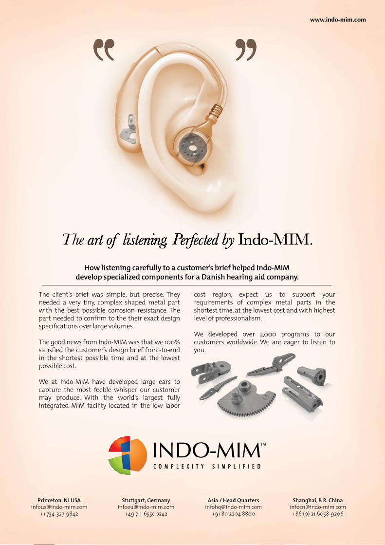
Powder Injection Moulding International June 201332 © 2013 Inovar Communications Ltd Vol. 7 No. 2
| contents page | news | events | advertisers’ index | email |

June 2013 Powder Injection Moulding International 33Vol. 7 No. 2 © 2013 Inovar Communications Ltd
| contents page | news | events | advertisers’ index | email |
MIM soft magnetic materials: Processing, properties and applications
Metal Injection Moulding has long been recognised as an effective route for the manufacture of soft magnetic components. In addition to the advantages that net shape manufacturing brings for materials that can be both expensive and difficult to machine, MIM processing also offers improved magnetic properties and a greater freedom in materials selection. Dr David Whittaker reviews the processing, properties and applications for a group of materials that is attracting increasing interest from end-user industries.
MIM soft magnetic materials
Soft magnetic components already represent an important area of applica-tion for Metal Injection Moulding (MIM) and there are encouraging signs that their importance will increase further. The main drivers for the use of MIM in processing of soft magnetic materials are:
• The higher achievable sintered density levels, compared with conventional press/sinter PM, ensure enhanced levels of key soft magnetic properties such as low coercivity
• MIM’s net shape capability ensures high material utilisation in applica-tions that often utilise relatively expensive material types
• Emerging designs of magnetic devices are increasingly calling for soft magnetic cores with the type of 3-dimensional shape complexity that MIM is ideally placed to deliver (Fig. 1)
• The miniaturisation of certain electrical devices has opened up opportunities for µMIM.
The unique characteristics of MIM processing also offer a number of benefits, as compared with processing of soft magnets from wrought feedstocks or, even, by conventional
press and sinter PM. Firstly, the use of two-colour MIM allows the incorpora-tion of soft magnetic and non-magnetic materials within the same part.
Secondly, the lack of plastic deformation in the processing of the powder content of the MIM feedstock avoids the work hardening of certain soft magnetic material grades and therefore extends the range of allowable compositions. This lack of deformation in the MIM product can also, on some occasions, allow the final
annealing treatment to be eliminated from the required processing route.
This article will return to these issues in later sections. In the following sections a brief introduction to soft magnetism and the magnetic proper-ties of key importance will be given, the leading soft magnetic material types, being processed by MIM, will be identified and discussed and published information on processing require-ments for these materials will be briefly reviewed.
Fig. 1 This print wheel is the heart of a 24 dot matrix printer head manufactured from a 3% silicon iron soft magnetic alloy (Courtesy Parmaco Metal Injection Molding AG)

Powder Injection Moulding International June 201334 © 2013 Inovar Communications Ltd Vol. 7 No. 2
| contents page | news | events | advertisers’ index | email |MIM soft magnetic materials
The relative behaviours of the two material types are shown in their magnetic hysteresis curves, as in Fig. 2 [1]. Soft magnetic materials have much narrower hysteresis curves. The typical hysteresis curve for soft magnetic materials, Fig. 3 [1], identifies the magnetic properties that are of significance in all applications:
• The maximum permeability (µmax), which is the slope of the line from the origin to the knee of the initial B-H magnetisation curve. This parameter defines how quickly the material is magnetised in the presence of an applied field and should preferably be as high as possible.
• The maximum induction (Bm), which is the maximum value
of induced magnetism in a DC hysteresis loop. This parameter is dependent on the magnetising field applied and data are gener-ally reported at specific levels of magnetising field, for example in MPIF Materials Standard 35, Metal Injection Molded Parts (2), at 1,990 A/m and 39,800 A/m. Bm is a measure of how much magnetic flux per unit volume the material can deliver. Again, Bm is desired to be as high as possible.
• The coercive field or coercivity (Hc), which is the DC magnet-ising field required to restore magnetic induction to zero. For soft magnetic materials, Hc should be as low as possible. For components that form part of an electromechanical convertor, the power that has to be applied for the complete switching process is related to Hc.
In materials that are processed by MIM (or press/sinter PM, for that matter), high sintered density emerges as a parameter that favours good soft magnetic properties, as defined by the desired levels of the above magnetic properties. The beneficial influence of high sintered density is shown in Fig. 4 [3].
Also, grain size is an important microstructural parameter. Grain boundaries restrict magnetic domain wall movement; therefore, finer grain size means a higher number of grain
Fig. 2 Hysteresis curves for hard and soft magnetic materials [1]
Fig. 3 Soft magnetic hysteresis curve [1]
Fig. 4 Magnetic properties of Fe-3% Si.10 [3]
Fig. 5 Effects of sintering temperature on density, hardness and carbon content of metal injection moulded Sendust alloy compacts using gas and water atomised powders [8]
In addition, developed standards and applicable quality control methods for MIM soft magnetic materials will be considered, along with current market penetration, application examples and finally future prospects for further growth in the demand for MIM soft magnetic parts will be discussed.
Important properties in soft magnetic applicationsSoft magnetic alloys are materials that are relatively easily magnetised and demagnetised in the presence of an external magnetic field, in contrast to hard (permanent) magnetic materials that, once magnetised, need a significant applied field to demagnetise them.
Sintering Temperature °F
Sintering Temperature °C
Co
erci
ve f
ield
, A/m
Mag
net
ic In
du
ctio
n, t
esla
Den
sity
, kg
/m2
2100 2200 2300 2400 2500 2600
1100 1150 1200 1250 1300 1350 1400
1.6
1.4
1.2
1.0
0.8
0.6
0.4
0.2
7400
7200
7000
6800
200
180
160
140
120
100
80
60
40
Bm
Br
Hc
Rel
ativ
e d
ensi
ty (
%)
Har
dn
ess
(HRC
watergas
Powder
100
95
90
85
80
55
50
45
40
35
0.025
0.02
0.015
0.01
0.005
0
Car
bo
n c
on
ten
t (m
ass%
)
1453 1473 1513 1513 1533 1553
Sintering temperature (K)

June 2013 Powder Injection Moulding International 35Vol. 7 No. 2 © 2013 Inovar Communications Ltd
| contents page | news | events | advertisers’ index | email | MIM soft magnetic materials
boundaries and a higher coercivity [3]. The general rule of thumb is that larger grains promote more favourable magnetic properties.
In addition to the above parameters, for high frequency applications, core or iron losses should be as low as possible, as these losses represent an inefficiency in the system. Core losses can be sub-divided into two constituent parts, hysteresis losses and eddy current losses. Hysteresis losses can be minimised by keeping the hysteresis loop as narrow as possible, i.e. Hc as low as possible. In the soft magnetic materials of interest here, low eddy current losses generally go hand-in-hand with high electrical resistivity.
For operating conditions at higher temperatures, the Curie point or Curie temperature can also be an important parameter. The Curie point is the temperature above which the material loses its ferromagnetic properties.
For particular applications, other parameters may also come into play including corrosion resistance and mechanical strength.
Soft magnetic material typesBecause of their electron configura-tions, paths and spins, which are beyond the scope of this review to discuss, the exhibiting of ferromagnetic properties is restricted to alloys based on the elements of the Fe group i.e. Fe, Ni and Co.
In addition to plain iron, the alloy types which find use in MIM soft magnets can be categorised as follows:
Fe-P alloys Phosphorus can be added to plain iron, at around the 1 wt% level to improve permeability. Also, the addition of phosphorus and molybdenum to create higher sintering activity (ferrite phase sintering) and promote higher sintered density and pore rounding and, hence, an improvement in both mechanical and magnetic properties in conventional press/sinter PM has been discussed in a recent conference paper [4].
Low alloy steels Low alloy steels incorporating other alloying additions to increase mechan-ical strength. For instance the grade MIM-2200, included in MPIF Standard 35, includes additions of around 2% Ni and 1.0% max. Si.
Fig. 7 The dependence of the coercive force of the concentration of phosphorus in the materials of Fe-7% Si-P, sintered at a temperature of: ●- 800°C; ▲ - 900°C; ∆ - 1000°C; × - 1100°C; ○ 1200°C [8]
Fig. 6 Dependence of nitrogen concentration with the concentration of phosphorus in iron, phosphorus-doped and sintered in a nitrogen gas (him. analysis) [8]
Fe-Si alloys These alloys exhibit low core losses and high electrical resistivity in AC and DC applications. These alloys readily work harden in conventional processing and even in conventional PM compaction and, for this reason, the silicon content is often restricted to 3% maximum. However, this restric-tion does not apply in MIM and work on Fe-6.5%Si has been reported (5) and at least one leading MIM supplier includes an Fe-9% material in its catalogue.
Fe-Ni alloys, or“Permalloys”These alloys have high permeability and low coercivity and are used in motors, switches and relays and for magnetic shielding applications. Permalloys are used at two different Ni levels, 50 wt% and 80 wt%, and there is also a “molybdenum permalloy” grade (80% Ni, 4% Mo, balance Fe). The 80% Ni grade has a higher permeability than the 50% Ni grade.
Fe-Co alloysThe 50% Co grade, also known as Permendur, is the most commonly used alloy in this family. Fe-Co alloys produce the highest magnetic satura-tion, surpassing that of pure iron, and are suitable for small components required to carry high magnetic flux densities. These alloys are notoriously brittle and difficult to machine in conventional processing and are often colloquially known as crack alloys (6). To aid machinability in conventional processing, a 2% vanadium addition is often made to this alloy. Processing by either MIM or press/sinter PM allows this addition to be omitted, therefore generating some material cost savings.
Ferritic stainless steels These steels, for example 430L combine good magnetic response with corrosion resistance and are suitable for applications in a corrosive environ-ment where protective coatings are not a practical option.
Co
nce
ntr
atio
n n
itro
gen
**1
00, w
t.%
Concentration P, wt.%
Concentration P, wt.%
Hc,
A/m

Powder Injection Moulding International June 201336 © 2013 Inovar Communications Ltd Vol. 7 No. 2
| contents page | news | events | advertisers’ index | email |MIM soft magnetic materials
Processing considerations Early guidelines for the processing of MIM soft magnetic parts were set out over 20 years ago in a publication from Chaman Lall [7].
From this publication and other sources, it can be defined that critical challenges in the processing of soft magnets, in order to optimise magnetic properties, are that:
• The effects of work hardening during the forming process must be removed from the final product. These effects make soft magnets “harder” in magnetic terms (i.e. higher coercivity) as well as in mechanical property terms.
• A coarse final grain size should be generated.
• As high a density level as possible should be generated in the final product.
• The levels of a number of residual elements, such as C, O, N and S, should be as low as possible in the final product.
In the processing of soft magnets from wrought feedstocks and, even, by the conventional press/sinter PM route, the first two of these challenges are generally met by using a final annealing heat treatment.
In MIM processing, however, work hardening does not occur in forming and therefore annealing is not required for the first of these reasons. Also, published work [5] has shown that grain growth can be generated by using a high sintering temperature. Thus, elimination of the separate annealing treatment is possible.
The work reported by Bulger and Zhang [1], summarised in Tables 1 to
Ni Powder Used Condition Carbon
Added? Bmax (gauss) µmax
Coarse As-sintered Yes 4267 25266
Coarse As-sintered No 4616 30450
Coarse With HIP Yes 4793 28590
Coarse With HIP No 4926 26470
CoarseWith HIP &
annealYes 4700 34010
CoarseWith HIP &
annealNo 4860 27160
Fine As-sintered No 6061 31540
Table 3 Moly Permalloy magnetic properties [1]
AlloyTheoretical
density (g/cc)
CarbonAdded?
Density (No HIP)
(g/cc)% theoretical
Density (w/ HIP) (g/cc)
% theoretical
Fe-50% Co 8.30Yes 7.82 94.2% 8.12 97.8%
No 7.84 94.4% 8.12 97.8%
Fe-3% Si 7.65Yes 7.58 99.1% 7.56 98.8%
No 7.56 98.8% 7.56 98.8%
Moly Permalloy(coarse powder
8.65Yes 7.15 81.7% 7.44 85.0%
No 7.23 82.6% 7.53 86.1%
Moly Permalloy(fine powder)
8.65 No 7.88 91.1%
Table 4 Density results [1]
Condition Carbon added? Bmax (gauss) µmax
As-sintered Yes 14.17 3270
As-sintered No 14.53 3527
With HIP Yes 13.36 2683
With HIP No 13.98 2816
With HIP & anneal Yes 13.98 3066
With HIP & anneal No 14.01 2980
Table 1 Fe-3%Si magnetic properties [1]
Condition Carbon added? Bmax (gauss) µmax
As-sintered Yes 19.33 3997
As-sintered No 19.63 4940
With HIP Yes 20.63 4400
With HIP No 21.19 5553
With HIP & anneal Yes 20.91 4860
With HIP & anneal No 20.56 3603
Table 2 Fe-50%Co magnetic properties [1]

June 2013 Powder Injection Moulding International 37Vol. 7 No. 2 © 2013 Inovar Communications Ltd
| contents page | news | events | advertisers’ index | email |
The concept of adding carbon to the initial material mix as an aid to reducing the oxygen level in sintering has also been explored by a number of authors, with variable results being reported.
The addition of carbon black for this purpose was a further processing variant reported by Bulger and Zhang [1]. Their results, shown in Tables 1 to 3, indicate that the approach did not offer a general benefit for the range of MIM soft magnetic grades studied and needs to be justified on a case-by-case basis. On the other hand, Miura and Kang [5] showed the benefits of using a high-carbon carbonyl iron powder in reducing as-sintered oxygen levels in Fe-50%Ni products. Fig. 8 shows the effectiveness of this approach in dramatically reducing as-sintered oxygen content while avoiding any significant increase in as-sintered carbon content.
MIM soft magnetic materials
3, indicated that the inclusion of a final annealing treatment in the MIM processing of Fe-3%Si, Fe-50%Co and Molybdenum Permalloy gave mixed results with the majority, in fact, showing a negative influence on magnetic properties.
For most soft magnetic grades, high sintered density can be achieved in MIM products directly from high temperature sintering, for example as shown in Fig. 5 [5]. However, recent attention has also been paid to assessing the potential benefits of a post-sintering Hot Isostatic Pressing (HIP) treatment to create further densification. This issue was also reported on by Bulger and Zhang [1]. Their results, presented in Table 4, suggest that HIP did show improvements in magnetic properties when as-sintered MIM materials had appreciable residual closed porosity that could be eliminated.
Turning to the final processing challenge on the list, the classical approach devoted careful attention to sintering atmosphere selection, particularly with regard to controlling final oxygen contents.
Traditionally, the preferred atmos-pheres have been dry hydrogen or vacuum [7]. However, recent work by Dorogina and Balakirev [8] has shown that plain iron and Fe-Si alloys can be effectively sintered in a 95%N2/5%H2 atmosphere if a phosphorus addi-tion of around 0.5% is made to the material mix. Fig. 6 shows how this addition can dramatically reduce the concentration of nitrogen absorbed from the sintering atmosphere and Fig. 7 shows the consequent lowering of coercivity of Fe-7%Si at high sintering temperatures.
Standards and quality control procedures The only established industry standard that refers to soft magnetic MIM grades is the MPIF Standard 35 “Metal Injection Molded Parts”, 2007 Edition (2). This standard covers the following grades:
• MIM 2200 (Fe, 2%Ni, 1% max Si)• MIM-Fe-3%Si• MIM-Fe50%Ni• MIM-Fe50%Co• MIM-430L (ferritic stainless steel)
The typical magnetic properties, quoted in this standard for these grades, are shown in Table 5. The standard also quotes typical mechan-ical properties.
Commercial equipment is available for the measurement of magnetic properties of sintered MIM parts.Full characterisation of the DC or
Fig. 9 Magnetising coil and parts holder for magnetic saturation measurement [9]
Fig. 10 Sensor arrangement for coercive force measurement [9]
Fig. 8 Effect of powder type on impurity contents of metal injection moulded Fe–50Ni compacts [5]

Powder Injection Moulding International June 201338 © 2013 Inovar Communications Ltd Vol. 7 No. 2
| contents page | news | events | advertisers’ index | email |MIM soft magnetic materials
AC hysteresis loops can be carried out, but it is a rather cumber-some method and is generally only used during the sampling process for a new component application. However, specialised characterisation equipment can be used for the rapid measurement of magnetic saturation, Fig. 9, or coercivity, Fig. 10 [9].
Established markets and applicationsThe proportions of MIM parts made from soft magnetic materials and the leading application types vary significantly between the different geographical regions of the global industry.
The data published by the JPMA [10] give a representative picture of the
position in Asia. As can be seen from Fig. 11, magnetic materials accounted for around 15% of total MIM produc-tion (by weight) in 2011.
The equivalent data for Europe, Fig. 12, show that soft magnetic grades make up around 5% of MIM material usage [11].
In North America, a recent survey of MIMA members [12] has indicated that the soft magnetic material MIM market share is at an intermediate level of around 7% by weight.
The key to these variations in penetration levels lies in the different market application sectors that the different geographical regions serve with MIM products. Previously published data have been presented, for instance in [13], that show IT and communications equipment to be the most important customer sectors in Asia, the automotive sector to be the dominant application sector in Europe (with a low level of IT activity) and most of the North American business to be split fairly evenly between automotive, mechanical equipment and medical sectors, with a relatively small contribution from IT applications.
Fig. 13 A MIM dot matrix printer yoke manufactured from Permendur (Courtesy Nippon Piston Ring, Japan)
Fig. 14 Another example of a MIM Permendur dot matrix printer yoke (Courtesy Epson Atmix Corporation, Japan)
Stainless steel 60.40%
Magnetic materials 15.30%
Fe-Ni base alloy 11.40%
Low alloy steel 3.30%
Heavy alloy 3.20%
Tool steel 2.60%
Others 3.80%
MIM materials in Japan, 2011
Fig. 11 Breakdown of MIM materials usage in Japan, 2011, showing the importance of soft magnetic materials (Data JPMA)
Stainless steel 50%
Soft magnetic materials
5%
Titanium 1%
Low alloyed steels 25%
Others 19%
MIM materials in Europe
Fig. 12 Breakdown of MIM materials usage in Europe, as presented at the PM2012 World Congress [11]
Material Typical Values
Designation Magnetic Properties
Code, as-sintered
MaximumPermeability
µ max
Hc
A/mBr T
B25
TB100
T
MIM-2200 2,000 120 0.8 1.45 2.0
MIM-Fe50%NiGrade 1Grade 2
47,50027,000
1016
1.01.0
1.41.4
1.51.5
MIM-Fe-3%SiGrade 1Grade 2
8,5006,000
5680
1.21.2
1.451.45
1.951.90
MIM-Fe-50%Co 5,200 120 1.4 2.0 2.2
MIM-430L 1,500 140 0.55 1.15 1.58
Table 5 Typical magnetic properties for soft magnetic grades

June 2013 Powder Injection Moulding International 39Vol. 7 No. 2 © 2013 Inovar Communications Ltd
| contents page | news | events | advertisers’ index | email | MIM soft magnetic materials
IT applicationsIn the IT sector, applications for MIM soft magnets can be found, for example, in printers and disk drives.
Dot matrix printer yokes (Figs. 1, 13 and 14) are a main driver of demand for MIM soft magnets, particularly in Asia. These parts are frequently made from Permendur (Fe-50%Co). Although dot matrix printers may seem like yesterday’s technology to many in the western world, there is still a deep-rooted demand in commercial printers and in consumer goods in developing countries. There was a reported softening of demand for these parts in 2012, but this market is now recovering in 2013.
Other examples of MIM soft magnetic applications in the IT/communications sector are conven-
tional hard disk drive parts, such as the three miniature Fe-Ni parts (Fig. 16), each weighing less than 1 g, which won an MPIF Overseas Grand Prize for AMT, Singapore. These parts were used in the world’s first 1.8 inch hard disk drive. One of these MIM parts maintained the distance between the magnet housing plates, guides and spring locators, while the other two parts functioned inside the magnet housing.
Automotive applicationsIn the automotive sector, there are many MIM soft magnet applications for actuators, sensors, motors and solenoids in the growing number of electromechanically activated auxiliary systems e.g. braking, traction, stability and other control systems.
A particularly important automotive application is the solenoid armature in the diesel engine common-rail fuel injector system. In [3] it was identi-fied that a MIM Fe-3%Si armature compared favourably with a wrought Fe-2.5%Si armature in terms of magnetic properties. Fe-Co alloys are also used in this type of application to generate high forces in small volumes and to minimise switching times. This type of application is well-established in both Europe and North America and Japanese MIM suppliers are becoming increasingly interested in them as they seek to combat over-reliance on printer yokes. Fig. 17 shows fuel injector parts produced by Nippon Piston Ring of Japan.
This MIM soft magnetic solenoid base manufactured by Indo-US MIM Tec (P) Ltd (Indo-MIM) offers the combination of excellent magnetic properties and high corrosion resistance. Manufactured from MIM Fe3%Si, the component is 10 mm x 28 mm x 31mm and weighs 17 g.
In the customer’s development of the part, MIM was attractive not only because of the non-availability of requisite material in wrought form, but also because of the number of process steps that alternative manufacturing routes required. These included an initial stamping, after which magnetic pins had to be welded to non-magnetic circular
sheet metal, which then had to be electroless nickel plated. All these processes increased manufacturing costs and decreased the quality of the component. The perpendicularity of the pins was difficult to maintain since the pins were being welded on to the sheet metal.
The requirement was close toler-ances added to the suitability of the part for MIM. The core and cavity in the tool accommodated the nine pins, which eliminated the welding and stamping operations, improving the final product. Indo-MIM states that it created a multi cavity tool to further improve efficiencies in high volume production.
Case Study: Solenoid base
Fig. 16 MIM soft magnetic Fe-Ni hard disk drive parts used in the world’s first 1.8 inch hard disk drive which won an MPIF Grand Prize in 1993 and was an early success for MIM technology in high volume soft magnetic applications
Fig. 15 A MIM Fe3%Si solenoid base (Courtesy Indo-MIM, India)
Fig. 17 MIM injector parts for an automotive fuel control system manufactured from PB Permalloy 47%Ni-Fe (Courtesy Nippon Piston Ring, Japan)

Powder Injection Moulding International June 201340 © 2013 Inovar Communications Ltd Vol. 7 No. 2
| contents page | news | events | advertisers’ index | email |MIM soft magnetic materials
General engineering applicationsMIM soft magnet uses in general (mechanical) engineering applications include:-
• The pole, manufactured from Permalloy (Fe-80%Ni), was produced by AMT, Singapore (Fig. 18). This pole is part of the instrumentation unit used in a valve system, utilised in the power, oil and gas industries and in pulp and paper plants.
• This body assembly, also produced by AMT, Singapore, is part of the control unit used in a valve system (Fig. 19). Such valves are normally used in the power, oil and gas industries and pulp and paper plants. The material is alloy 52 (50%Ni-Fe).
use of the capabilities of “2-colour” MIM for the incorporation of materials with different properties in a single component.
The MikroMag demonstrator, already cited above, combines materials with soft magnetic and hard magnetic properties. Reference [3] cited applications, such as motor rotors, which combine a non-magnetic hub with a magnetic outside diameter.
Future prospects for MIM soft magnetic productsAlthough MIM soft magnets have already generated significant market penetration, there are pointers towards new growth opportunities.
New opportunities for MIM soft
Fig. 19 This MIM body assembly is part of the control unit used in a valve system. MIM enabled the integration of four conventional components into one, thereby enhancing performance and leading to a 30% cost saving. (Courtesy Advanced Materials Technologies Pte Ltd, Singapore)
Fig. 18 This MIM Permalloy (80% Ni-Fe) pole is part of the instrumentation unit used in a valve system. These poles have extremely high magnetic permeability (Courtesy Advanced Materials Technologies Pte Ltd, Singapore)
Fig. 21 Low thermal expansion MIM parts for measurement systems that are used for determining the pressure inside cylinders. Material: 42%Ni-Fe (Courtesy Epson Atmix Corporation, Japan)
• The demonstrator part, developed in a collaborative German project, MikroMag, which involved Siemens as the end-user. This part (Fig. 20) makes use of multi-component MIM by overmoulding the soft magnetic sensor outside the rotary encoder. Applications, identified within Siemens products, include tooling identification in automatic machining centres.
• These low thermal expansion metal parts (Fig. 21), produced by Epson Atmix, Japan, are from measurement units used for determination of pressure inside cylinders. The material is Fe-42%Ni.
There are a number of examples in the market of applications that make
Fig. 20 This MikroMag demonstration part combines materials with soft magnetic and hard magnetic properties. Applications include tooling identification in automatic machining centres. The part makes use of multi-component MIM

June 2013 Powder Injection Moulding International 41Vol. 7 No. 2 © 2013 Inovar Communications Ltd
| contents page | news | events | advertisers’ index | email |
magnetic parts can be expected from the continuing growth in electro-mechanically activated automotive systems. Around a decade ago, reference [3] predicted that these new components would include solenoids, motors and sensors and that, for instance, the number of sensors per vehicle might increase from 100 to 300.
At that time, it was widely assumed that vehicle battery technology would need to migrate to 42 volts to power this increase in devices and, indeed, reference [3] was from a 42-volt tech-nology session at the SAE Congress. In fact, since then, means have been found of tackling the increased demand with existing 12/14 volt systems and so the migration to 42 volts has not materialised, but the predicted increase in devices has happened and continues to happen.
One automotive application that has not yet been introduced but continues to be “touted” is the replacement of mechanical engine valve activa-tion, using camshafts connected to crankshaft rotation through an engine timing system, with electromagnetic valve actuation.
Information technology and high frequency power electronics are predicted to offer high growth potential for soft magnetic applications (14).
The aerospace sector may also offer growing market opportunities, as it seeks to introduce “more electric aircraft” concepts that will replace hydraulic or pneumatic actuation with electromagnetic actuation in many on-board systems. As part of these developments, generators will be placed inside aero-engines on the main engine shafts.
The extension of opportunities for 2-colour MIM technology can be expected. For instance, a recently filed patent from Bosch (15) for an electro-magnetically actuable valve, calls for
the manufacture of magnet armatures for fuel injection that comprise soft magnetic sectors separated by webs of insulating (ceramic) material to reduce eddy current losses. This development is expected to contribute to improved fuel efficiency and reduced emissions.
New opportunities for µ-MIM can also be anticipated as micro-
electro-mechanical systems (MEMS) are commercialised (16). These systems will integrate devices such as micro-reactors, micro-mixers, micro-actuators and micro-sensors.
AuthorDavid WhittakerDW Associates231 Coalway RoadWolverhampton WV3 7NGUnited KingdomTel/Fax: +44 1902 338498Email: [email protected]
References[1] M Bulger and H Zhang, “Processing of MIM Soft Magnetic Alloys”, Paper at PowderMet 2012, Nashville, Tennessee, 10-13 June, 2012.
[2] MPIF Standard 35, Metal Injection Molded Parts, 2007 edition, MPIF, Princeton, New Jersey, USA.
[3] M N Gross and M L Anderson, “Soft Magnetic MIM Parts for Diesel Engines”, SAE Paper 2003-01-0445, 2003 SAE World Congress, Detroit, Michigan, March 3-6, 2003, taken What is Powder Metallurgy (MPIF) 2002.
[4] K Dollmeier, I W Donaldson and P Sokolowski, Paper at PM-13 India.
[5] H Miura and H Kang, “Application of metal injection moulding to soft magnetic materials”, Powder Metallurgy, Vol.56, No.1 (February 2013), p. 38-45.
MIM soft magnetic materials
[6] M J Dougan, “High Performance Sintered Soft Magnetic Materials”, Paper at World PM Congress 2010.
[7] C Lall, “Soft magnetism – Fundamentals for Powder Metallurgy and Metal Injection Molding”, MPIF, Princeton, New Jersey, USA.
[8] G A Dorogina and V F Balakirev, “Nitrogen Gas as the Atmosphere for Sintering of Soft Magnetic Materials Based on Iron”, Proceedings of World PM Congress 2010, Volume 5.
[9] P Sansieri, Paper at PowderMet 2012, Nashville, Tennessee, 10-13 June, 2012.
[10] 2011 Report for the MIM market, JPMA.
[11] F Petzoldt, Powder Injection Moulding International, Vol. 6, No. 4, December 2012, p. 47.
[12] Private communication from B Dionne.
[13] D Whittaker, “Powder injection moulding looks to automotive applications for growth and stability”, Powder Injection Moulding International, Vol. 1, No. 2, June 2007, p. 14-22.
[14] UK PM Foresight Report: The PM Industry in the UK – the next ten years.
[15] US Patent Publication US20120305816 A1.
[16] K Nishiyabu, K Okubo and S Tanaka, “Filling Behaviour and Magnetic Properties of Fe-45Ni Permalloy Micro-MIM Parts”, Paper at Euro PM2012, Session on Powder Injection Moulding - Special Materials 2.
“The aerospace sector may also offer growing market opportunities, as
it seeks to introduce “more electric aircraft” concepts that will replace
hydraulic or pneumatic actuation with electromagnetic actuation”

Powder Injection Moulding International June 201342 © 2013 Inovar Communications Ltd Vol. 7 No. 2
| contents page | news | events | advertisers’ index | email |

June 2013 Powder Injection Moulding International 43Vol. 7 No. 2 © 2013 Inovar Communications Ltd
| contents page | news | events | advertisers’ index | email |
Megamet: Expansion and diversification at one of North America’s fastest growing MIM firmsThe US MIM industry continues to enjoy exceptional levels of growth thanks to strong demand from the region’s two largest consumers of MIM parts, the firearms and medical device sectors. Megamet Solid Metals Inc. is one of the fastest growing North American MIM companies, with its success to-date achieved on the back of a strong relationship with the firearms industry. Nick Williams visited the company and reports on a steadily expanding operation that has its sights set on creating above-average growth through diversification into new markets.
Megamet Solid Metals
Located in Earth City, a commercial region on the outskirts of St Louis, Missouri, Megamet Solid Metals Inc. is one of North America’s fastest growing manufacturers of MIM parts. Megamet is part of the CIC Group Inc., a privately owned holding company comprising a diverse range of businesses, from thermal spray specialists to metal fabricators for the oil and gas industry and one of the world’s largest producer of heat recovery steam generators. Together the companies in the group generated sales in excess of $1 billion in 2012. Megamet is one of the smallest but fastest growing companies in the group.
The history of MegametThe precursor to the current business was formed in the late 1980s as Megamet Industries with the intention of creating a business as a MIM feedstock provider. This was still a relatively early period in terms of the commercialisation of MIM in North America and a time when the concept of purchasing MIM feedstock from a third-party, as an alternative to
in-house development or technology licensing, was a relatively new concept. In Europe, BASF was also developing its Catamold system with similar intentions, a product that became commercially available in the early 1990s.
It was during the efforts to commercialise the company’s
feedstock system that MIM part and tool production commenced as a route to generate revenue. The company, however, had only limited success and the plan to sell its MIM feedstock, which was based on catalytic binder removal, was eventually abandoned.
It was in May 2002 that the CIC Group took the opportunity
Fig. 1 Exterior view of Megamet’s 35,000 ft2 MIM plant in Earth City, Missouri

Powder Injection Moulding International June 201344 © 2013 Inovar Communications Ltd Vol. 7 No. 2
| contents page | news | events | advertisers’ index | email |Megamet Solid Metals
to acquire Megamet Industries, renaming it Megamet Solid Metals. As well as discontinuing feedstock manufacturing, the company ceased all tool manufacturing operations and made the decision to focus solely on MIM parts production.
It took around five years from the acquisition of Megamet Industries for CIC to turn the company into a financially and technologically feasible concern. The business model was completely re-evaluated, staff appraised and equipment upgraded or replaced. “By 2008 we were in a good place,” stated Bruce Dionne, Megamet’s General Manager and Vice-President. “Our operation was both viable and technically sound with a growing client base.”
A plant designed for growth In 2010 Megamet relocated to a larger facility close to its original premises in Earth City. The current 35,000 ft2 of floor space gave the company’s management the freedom to design both the administrative and production facilities to meet the future needs of the business. The facility currently operates three shifts, five days a week.
Dionne stated, “Moving to these new premises allowed us to design our facility around our growth plans. As a result, new capacity can be easily added with zero disruption to existing production. Our new manufacturing area has all services pre-installed and ready for connection with new equipment as it is required. This
includes space for a significantly increased number of injection moulding machines, plus additional batch debinding, batch sintering, and continuous pusher sintering furnaces.” Dionne added, “Our parent company has recognised what has been achieved at Megamet since it was purchased and has been supportive of our planned investments in capacity.”
Injection moulding currently takes place using four machines, one of which operates with a 6-axis robot and indexing conveyor system for the efficient production of high volume parts. Investment plans for the injection moulding facility are well underway, with a new Arburg machine soon to be delivered. “We are about to trial a new Arburg Allrounder machine with a view to increasing our capacity in-line with our strategic vision for the coming years. The machine, fitted with robotic part handling capabilities, is expected to help further improve our operational efficiency as well as our ability to process smaller components to even higher tolerances,” Dionne told PIM International.
In 2008 Megamet acquired its first continuous furnace, a CM Furnaces pusher furnace, supplementing the existing range of batch debinding and sintering furnaces, also manufactured by CM Furnaces. “It has always been our intention to grow in a fashion that allows both small and large jobs to be processed in the most efficient way possible. We typically manufacture parts with annual production volumes that range from 5000 to 500,000 so a combination of batch and continuous sintering solutions works very well for us,” commented Dionne.
In September 2012 a second continuous pusher furnace was installed in order to meet the strong year on year growth that the company has enjoyed since the completion of its restructuring in 2008. Dionne stated, “We now run one of our continuous furnaces with a hydrogen atmosphere for stainless steels and the other with a nitrogen atmosphere for low alloy steels. These materials make up the majority of our output, with low alloy steels accounting for around 60% of production and stainless steels 40%.” Soft magnetic materials are also processed, however these currently account for less than 2% of production.
First stage debinding takes place in one of several CM catalytic batch debinding furnaces. For second stage
Fig. 2 A section of the injection moulding area at Megamet
Fig. 3 Catalytic debinding ovens

June 2013 Powder Injection Moulding International 45Vol. 7 No. 2 © 2013 Inovar Communications Ltd
| contents page | news | events | advertisers’ index | email | Megamet Solid Metals
debinding and sintering the company operates a number of bottom loading batch sintering furnaces together with a range of smaller front loading sintering furnaces.
An example of the very practical approach that is taken at Megamet to increase efficiency and capacity is an innovative loading and unloading system for its bottom loading batch sintering furnaces. The system, which allows a furnace load to be removed whilst it is still warm and quickly be replaced with a new load, has significantly reduced turnaround time, thereby adding valuable additional capacity to the plant.
In-house finishing operationsMegamet has an extensive in-house machining and finishing capability and it regards such secondary operations as crucial in order to deliver a flexible and efficient service to customers. The finishing area includes multiple 3-axis CNC machining centres, a number of drilling, reaming and tapping machines, five coining presses, surface grinding stations and various other systems for the finishing of MIM parts. Local suppliers are used for heat treatment and surface finishing such as black oxide coating.
Megamet also machines all its custom alumina setters in-house, as well as performing tool maintenance. The fabrication of new and replacement injection moulding tools is out-sourced to external suppliers.
The advantages of purchasing feedstock One of the keys to the company’s transformation, believes Dionne, was the decision to adopt BASF’s Catamold feedstock system when the company was acquired by CIC Group. “This move left us free to focus on the most fundamental area of our business – MIM parts production.”
Dionne told PIM International that the company’s decision to purchase feedstock from an external source not only streamlined operations by eliminating the need for additional staff, equipment and laboratory facilities but also helped the company through some of the recent crises that affected materials supply to the industry.
“Thanks to the resources of BASF, the world’s largest chemical company, we experienced no production delays or materials shortages during episodes that proved very challenging for many in the MIM industry; namely the nickel powder shortages that resulted from industrial action and the MIM grade ferrous powder shortages that followed the Japanese earthquake and tsunami of 2011. We also received all necessary supplies of nitric acid for the catalytic debinding process after an explosion in May 2012 at a chemical plant in El Dorado, Arkansas, which dramatically affected global supply. The MIM industry is a very minor consumer of nitric acid, and therefore low priority for suppliers in the case of severe shortages, however BASF exerted its influence to ensure that supply was
maintained to its Catamold customers, thereby ensuring that MIM part production could be maintained. There is no other vendor who could have achieved this,” stated Dionne. “There is, of course, the benefit of also being able to assure potential customers that our material is manufactured and supplied by such a major global corporation, with all the assurances of quality, batch to batch consistency and security of supply that this brings.”
Megamet’s quality programme is certified to ISO 9001:2008 and obtaining ISO 13485 for the manufacture of medical devices is a current priority. Equipment in the on-site laboratory includes an optical gauging system, an optical comparator, a Leco carbon analyser, a magnetic particle inspection machine, a dye penetrant
Fig. 4 A view of two continuous pusher furnaces, with batch furnaces in the background
Fig. 5 Brown MIM parts entering a continuous pusher furnace

Powder Injection Moulding International June 201346 © 2013 Inovar Communications Ltd Vol. 7 No. 2
| contents page | news | events | advertisers’ index | email |Megamet Solid Metals
inspection station, Rockwell hardness testing systems, and a positive material identification system.
Management team and growth strategyMegamet’s management team has set ambitious growth targets for the coming years and recent performance clearly shows the company’s potential. “In a period of four years we will have increased our sales from $3 million to beyond $10 million and anticipate that within five years sales will surpass $20 million. This growth has been achieved thanks to a number of factors. We have a great team of very competent people in place, we’ve been recognised with numerous MPIF
awards and we have significantly increased our visibility thanks to an on-going marketing effort. My election as President of the Metal Injection Molding Association (MIMA) in 2011 also raised our profile significantly within the North American MIM industry,” stated Dionne.
Dionne joined Megamet in 2005 as Sales Manager, having previously worked in two other divisions of CIC. “As with any growing business, our jobs required us to perform a number of roles, from project management to qualifying tooling, engineering development and customer service.” Within three years he was appointed General Manager.
Another key member of the Megamet team is Phil McCalla, who
joined the company only a few months after Dionne as Project Manager. A well-known face within the North American MIM industry, he is now the company’s Operations Manager and also serves as Chairman of MIMA’s Standards Committee.
Dionne told PIM International, “One of Megamet’s big strengths is the fact that so many of our people are graduate engineers. This, combined with the fact that many have long standing positions within the corporation, brings a depth of knowledge of the MIM business and the technology that simply cannot be gained any other way. Richard Louis, who leads our sales team, also has a background in engineering. This is invaluable when building strong relationships with customers.”
Megamet’s parent company, CIC Group Inc., is an employee-owned company, a structure that is widely credited with delivering a number of advantages including a greater ability to retain an experienced and motivated staff, increased employee engagement, greater levels of productivity and a longer term approach to business planning and investments.
Markets for MIMThe firearms industry in the US has for many years been a major user of North American MIM components, with recent figures estimating that more than 40% of MIM components (by weight) produced in the region are for firearms applications. Like many other MIM firms in the US, Megamet has firmly established itself as a trusted supplier to the industry.
Commenting on the current surge in demand for firearms in the US, Dionne told PIM International, “In recent times there has been a clear spike in firearms sales at election time. As a result of the fear that some form of legislation could be passed in the coming years, sales of guns and ammunition have increased at unprecedented levels. As the situation currently stands, and because of a lack of the necessary support for new legislation in Congress, it is expected that uncertainty will remain for the remainder of the President’s second term and the frenzy will continue.”
The unprecedented demand for MIM components for firearms placed extreme pressure on the capacity of
Fig. 6 Batch furnaces of various sizes at Megamet
Fig. 7 A view of part of the machining and finishing area

June 2013 Powder Injection Moulding International 47Vol. 7 No. 2 © 2013 Inovar Communications Ltd
| contents page | news | events | advertisers’ index | email | Megamet Solid Metals
many MIM producers who supply this sector. Dionne commented, “As we see it, gun manufacturers know that this is a spike in demand and as such they are not investing in additional capacity. It is an ideal situation for the gun industry, with demand outstripping supply and gun prices rising. We therefore do not see a need to increase our immediate capacity as a direct response to this spike. Our ongoing expansion will take place as part of our strategic growth plan that will bring an increase in the range of parts produced for both the firearms industry and other markets.”
Within the US firearms industry, Dionne believes that there are still significant growth opportunities for MIM. “We have helped companies that have never used MIM to adopt the process, dramatically increasing their success and profitability and securing them as loyal and committed customers. There are still huge opportunities for MIM in this sector, especially amongst the aftermarket producers where there simply isn’t the understanding of what MIM can offer them in terms of innovation and profitability.”
Megamet also supplies a number of other industry sectors and is actively pursuing new opportunities. “We are taking advantage of our growing reputation in the firearms industry to strengthen our position, whilst also leveraging our reputation to expand into other segments. Our focus outside of firearms is to grow our share in the industrial and medical segments by finding unique niches that value our innovative engineering services,” stated Dionne.
To achieve this goal Megamet is increasing its participation in manufacturing exhibitions across a range of end-user sectors and is in the process of developing a new website that will position the business as a supplier to a wider range of industries. The company’s sales efforts are primarily focussed on North America, however it is stated that a number of enquiries from further afield are being considered.
The company is also pursuing a number of opportunities relating to the in-house development of products that utilise MIM components. Dionne stated, “Innovation has been a cornerstone of our success and we see opportunities in the market where we can design products that solve unmet needs. In such cases we
Fig. 8 A selection of MIM parts in the green and as-sintered state
Fig. 9 MIM parts for a 1911 pistol
Fig. 10 MIM components manufactured by Megamet for the AR-15 rifle

Powder Injection Moulding International June 201348 © 2013 Inovar Communications Ltd Vol. 7 No. 2
| contents page | news | events | advertisers’ index | email |Megamet Solid Metals
Fig. 16 Parts used in a hand tool (Photo MPIF)
2003: Open centre impellerA 2003 MPIF Award of Distinction in the Industrial Motors/Controls category was awarded to Megamet for a complex 316L stainless steel impeller (Fig. 11) that is a critical component in an industrial sensor. An eddy-current device, the impeller measures the flow of hazardous materials in chemical processing plants. It is injection moulded to produce all features except for the hub, which is reamed for the required press-fit diameter and concentricity. The part is made to a minimum density of 7.9 g/cm3 and meets a minimum yield strength of 26,000 psi. Investment casting was originally considered but PM provided improved dimensional accuracy and a very substantial cost savings. The part is still in production today.
Fig. 14 Upswept safety grip (Photo MPIF)
Fig. 13 Rifle handle components (Photo MPIF)Fig. 12 Trigger guard (Photo MPIF)
Megamet’s MPIF award winning parts
2007: Trigger guard Winner of the 2007 MPIF Grand Prize in the Hand Tools/Recreation category was a MIM rifle trigger guard (Fig. 12) manufactured by Megamet for Modern Muzzleloading, Inc. The MIM guard supports the trigger group and hammer in the “quick detachable trigger” mecha-nism in a 50 caliber muzzle-loading hunting rifle.
The material selected for this project was BASF Catamold 42CrMo4, which meets AISI/SAE 4140 specifica-tions. Produced to a density of 7.4 g/cm3, the 88 g MIM steel part has an as-sintered tensile strength of 94,250 psi and a 58,000 psi yield strength. The part is held to critical dimensions of +/-0.005 inches.
Secondary operations for this part included reaming three holes, tapping
two screw holes and deburring. The part is provided to the customer in the as sintered condition and the customer applies the black oxide surface finish. The MIM process offered substantial cost savings.
2009: Rifle handle body and yokeMegamet received the 2009 MPIF Award of Distinction in the Aero-space/Military category for a MIM handle body and yoke (Fig. 13) for Colt Canada Corporation.
Made from 4140 low-alloy steel to a density of 7.4 g/cm3, the parts are core components in a folding-front-grip assembly that attaches to the Picatinny Rail system used on modern military rifles.
Challenges presented by the geometric complexity of the parts are efficiently and cost-effectively solved by the MIM process. Post-sintering operations included coining, reaming, and tapping. The components are quenched and tempered to a 45-50 Rockwell C hardness range. Parts are supplied to the customer with a manganese phosphate finish.
Fig. 15 Rifle rear sight (Photo MPIF)
The annual Design Excellence Awards from the Metal Powder Industries Federation (MPIF) have for many decades served to promote PM and MIM technology. Megamet has won a number of awards for its MIM components, all of which illustrate the advantages that the process can offer to end-users.
Fig. 11 Open centre impeller

June 2013 Powder Injection Moulding International 49Vol. 7 No. 2 © 2013 Inovar Communications Ltd
| contents page | news | events | advertisers’ index | email | Megamet Solid Metals
then brand those products and use a partner to sell and distribute them.” Megamet currently has a product with three patent applications pending which will utilise six MIM components and discussions are underway with potential distribution partners.
MIMA and the challenges ahead for the industryDionne is an enthusiastic supporter of the Metal Injection Moulding Association (MIMA), one of the six trade associations of North America’s Metal Powder Industries Federation (MPIF). Through his role as President of MIMA, and a member of the MPIF’s Board of Governors, he is an active participant in the association’s activities, one of which has been the organisation of the annual MIM conference, which he co-chaired in 2011 and 2012. Such work, he suggested, has had a significant and positive impact on the industry’s awareness of Megamet.
Dionne told PIM International, “MIMA is a very active association that is steadily enjoying a growth in interest from both US and overseas companies active in MIM, including parts producers and industry suppliers. As well as organising the annual international MIM conference, held each spring, and actively promoting MIM technology via our mimaweb.org website, the association has set itself the goal of increasing awareness of the MIM industry as a place that offers great career opportunities.”
Dionne explained that it is frequently commented upon that there is a distinct lack of awareness
of the MIM industry and its technology among graduates leaving college and university, making it especially hard to attract them to work in this sector. “Finding talented young engineers is tough. Thankfully we have been able to develop great people in-house, but we believe that more can be done to promote the potential of our industry to offer graduates a dynamic and successful career. We at Megamet are lucky to have a relationship with the nearby Missouri University of Science and Technology, which introduces PM and MIM through its engineering classes. As a result we have recently benefited from taking on a young metallurgical engineer. We have also worked with the university on a number of research projects and benefit from being able to use its facilities as neces-sary, an example being for SEM work.”
Contact Bruce G. DionneVice President - General ManagerMegamet Solid Metals, Inc.13748 Shoreline Ct. East Earth City, Missouri 63045 United States Tel: +1 314 801 6914Email: [email protected]
2010: Pistol upswept grip safety part Megamet won a 2010 MPIF Award of Distinction for an upswept grip safety part (Fig. 14) used in the 1911 style 45-caliber pistol made by Colt’s Manufacturing Company, LLC. The complex MIM 17-4 PH stainless steel part is produced to a density of 7.6 g/cm3.
The upswept design of the grip safety part, which was traditionally investment cast, would previ-ously require extensive secondary machining. Switching to the MIM process reduced customer lead times and provided exceptional cost savings, in addition to increasing production rates and producing a more uniform part. Colt performed a 10,000-cycle test to qualify the part.
2011: Rifle rear sightA rear sight (Fig. 15) used on sporting and military rifles such as the AR-15, M4, and M16 models, received the MPIF 2011 Award of Distinction in the Aerospace/Military category. Made by Megamet for Yankee Hill Machine Co., Inc., the nickel steel MIM part features very close tolerances and a complex geometry requiring an elaborate tool design.
The sight allows the shooter to target objects at ranges up to 200 yards by using the larger aperture, and to target objects at longer ranges by flipping the sight down and using the smaller aperture. The part is made to a density of 7.5 g/cm3 and has an as-sintered ultimate tensile strength of 55,000 psi. Choosing the MIM process over investment casting provides a 40% cost saving. Secondary operations are limited to tapping and nitride finishing.
2012: Cable-tie hand tool assemblyMegamet won the 2012 MPIF Award of Distinction in the recreation category for a cable-tie hand tool assembly of six 17-4 PH stainless steel MIM parts (pinion, nosepiece, pawl gripper, insertable rack, cutoff cam, and short link) made for HellermannTyton (Fig. 16). Made to a density of 7.6 g/cm3, the parts are produced to net shape with only four requiring minor secondary operations such as reaming and coining.
Fig. 17 MIM surgical jaw components manufactured by Megamet

Powder Injection Moulding International June 201350 © 2013 Inovar Communications Ltd Vol. 7 No. 2
| contents page | news | events | advertisers’ index | email |Industry News
POWDER METALLURGYPOWDER
METALLURGYREVIEWipmd.net
Inovar Communications Ltd
for the world of

June 2013 Powder Injection Moulding International 51Vol. 7 No. 2 © 2013 Inovar Communications Ltd
| contents page | news | events | advertisers’ index | email |
Elnik Systems: The next generation takes the helm at a leading innovator in batch furnace technology for MIM
Elnik Systems is widely recognised as a market leader in the production of batch debind and sintering furnaces for MIM, with the company’s MIM 3000 system operating for nearly 20 years at the heart of numerous MIM production facilities worldwide. As Stefan Joens succeeds his father Claus in the day to day running of the business, PIM International’s Nick Williams profiles the company and shares its management team’s insights into the global MIM business.
Fig. 1 A view of the 20,000 ft2 Elnik Systems / DSH facility in Cedar Grove, New Jersey
Elnik Systems
Batch sintering furnaces manufactured by Elnik Systems, based in Cedar Grove, New Jersey, USA, have over a period of nearly 20 years become a common sight when visiting MIM production plants, primarily in Europe and the Americas but also in Asia. As a result, the distinctive blue livery of the company’s furnaces is for many as synonymous with the MIM industry as the yellow and green livery of Arburg’s injection moulding machines.
This leading position is in part thanks to the company’s presence in the MIM industry in the early 1990s, a time of great change for the industry. MIM was starting to enjoy profitability for the first time and major new high volume applications such as airbag and disk drive components reflected a growing acceptance of MIM by end-users.
In 1992 BASF launched its new feedstock system, Catamold, which allowed MIM technology to be embraced by an even wider group of parts manufacturers and end-users. It was shortly after this that Elnik Systems commenced its development of a “one-step” debind and sinter partial pressure furnace specifically to meet the needs of the growing MIM
market. The system, MIM 3000, was launched in 1995 and provided a cost-effective alternative to the two-furnace technology then being used. The global MIM industry thrived throughout the 1990s, growing from sales of around $100 million to more than $700 million by the end of the decade. This rapid expansion in parts sales was mirrored by investments in production capacity, securing positions as key
industry suppliers for those equipment manufacturers who participated in this formative period for the industry.
The history of Elnik SystemsThe history of Elnik Systems can be traced back to 1969 when Elnik Instruments, Inc. was established in Hackensack, New Jersey, as a subsidiary of W H Joens & Co. GmbH,

Powder Injection Moulding International June 201352 © 2013 Inovar Communications Ltd Vol. 7 No. 2
| contents page | news | events | advertisers’ index | email |Elnik Systems
based in Germany. The company was initially involved in the sale and service of temperature recording devices used on manufacturing equipment such as furnaces, injection moulding machines and twin screw extruders. In 1982 the company decided to focus its efforts on the manufacture of complete vacuum furnace systems and within three years thirty furnaces had been built for the Raytheon Company in Waltham, Massachusetts, USA.
Demand for custom vacuum furnaces was increasing at a rapid pace and by 1986 Elnik Systems was formed. The company has since enjoyed steady growth, moving into new 20,000 ft2 premises in Cedar Grove in 1999. As well as housing the furnace construc-tion and administration areas, the facility also houses DSH Technologies,
an affiliate of Elnik that offers both toll sintering services and MIM technical support. The company employs 35 people in Cedar Grove and at its Californian field service office.
Elnik Systems has to-date manu-factured and installed around 560 furnaces, of which around 280 are dedicated MIM furnaces. Other applica-tions include heat treating, brazing and annealing. Of the installed MIM furnaces, 39% are in North America, 7% in South America, 40% in Europe and 14% are in Asia.
In the last decade annual sales have grown from $5 million to more than $10 million and there is confidence that the company will continue to grow and enjoy the same success over the next ten years.
The evolution of Elnik’s batch debind and sinter technologyElnik’s primary furnace system for the second stage debinding and sintering of MIM parts, the MIM 3000, has evolved over the years as a result of on-going research activities and the experience of maintaining and servicing such a large number of MIM furnaces worldwide.
Stefan Joens, Vice President of Elnik Systems, explained to PIM Interna-tional, “The initial furnace developed by Elnik to remove the second stage binder and then sinter the parts was in retrospect a great crutch for the latest state of the art MIM 3000 units sold today. The first MIM furnace was built in 1995 and since then, through heavy in-house use of the equipment at DSH Technologies and also working together with our customer base, we have made significant improvements and innovations in gas flow, tempera-ture uniformity and accuracy, process control automation, hotzone and retort strength, and durability. The automatic cleaning processes for the binder traps and the vacuum pump, which are the areas that see the heaviest flow of binder, have been enhanced and the user friendliness and record keeping of all process parameters for FDA, medical and aeronautic requirements have been developed to meet the necessary standards.”
Elnik states that its system was the first all refractory metal furnace with partial pressure operation from 10 mbar to 800 mbar for hydrogen, nitrogen or argon, with laminar gas flow via an internal retort to remove the second stage binder and then sinter the MIM parts, all in one process step. This shortened process time from what was typically more than 30 hours to around 20 hours.
The Accu-Temp systemThe Accu-Temp control system used on Elnik’s furnaces, states the company, ensures a more uniform temperature within the retort of the furnace, mini-mising variations in size and density anywhere inside the retort.
“Six zone temperature control with our proprietary Accu-Temp thermocouple correction program enables the furnace to have a very tight temperature control of +/- 1°C and uniformity inside the workspace of +/-
Fig. 2 A view of a series 3045 MIM furnace under construction at Elnik Systems
Fig. 3 The machine shop at Elnik’s manufacturing facility in Cedar Grove, New Jersey

June 2013 Powder Injection Moulding International 53Vol. 7 No. 2 © 2013 Inovar Communications Ltd
| contents page | news | events | advertisers’ index | email | Elnik Systems
3-5°C in order to process parts close to the solidus temperature, thereby increasing the density of the MIM parts to the highest levels,” stated Stefan Joens.
Laminar gas flowAnother feature of Elnik’s furnaces, states the company, is the use of laminar gas flow technology, providing efficient and effective gas management for debinding and sintering. Laminar gas flow is achieved at partial pres-sures between turbulent and molecular flow, enabling gas molecules to flow at sufficient velocity to allow the gas to move smoothly over surface irregularities and obstructions. Elnik’s furnaces are designed specifically around laminar flow and this enables the moving of a significant quantity of molecules per unit time from one place to another, ensuring the efficient debinding of MIM parts and guaran-teeing that all parts are covered with a sufficient volume of gas flow.
Development supported by DSH Technologies DSH Technologies, a wholly owned subsidiary of Elnik Systems, is regarded as one of the company’s greatest assets. DSH was created from the research and development activities of Elnik from the period when it was building vacuum furnaces for the defence and other industries. Claus Joens, Elnik’s founder and President, told PIM International, “When we started to produce furnaces for the processing of MIM parts and the furnaces became a success we were asked by various customers to sign Non-Disclosure Agreements. We therefore separated the research and development function and founded DSH Technologies, LLC, through which we were then able to sign NDA agree-ments and we still have many in place today.”
DSH, which stands for debind, sinter and heattreat, is housed in the same building as Elnik and operates produc-tion scale equipment that includes two MIM 3045 batch debind and sintering furnaces, a catalytic debind oven (CD-3045) and a solvent debind system (SD-3045). It also has a laboratory water debinding system at its disposal.
DSH is additionally equipped with a quality inspection laboratory where it has all the necessary equipment such
as a helium pycnometer for density measurement, a carbon analyser, metallographic equipment and scales, dimensional measuring and other common laboratory equipment.
Dr Satya Banerjee, Project Manager/Chief Metallurgist at DSH Technologies, has over 25 years of industrial experience, of which more than 20 have been in developing mate-rials, processes and products as well as setting up laboratory and production equipment in the MIM Industry.
Banerjee explained to PIM Inter-national, “DSH provides Elnik with a channel to prove the processing of MIM parts to potential customers who may be new to this technology. We are able to demonstrate that Elnik’s debind and sinter equipment works on their poten-
tial MIM parts before a commitment is made to purchase the equipment.”
Stefan Joens added, “The primary reason that we continue to provide real, functioning innovative improve-ments to our product line is the fact that concepts are tested out in the production MIM 3045 furnaces at DSH for a three to six month period to ensure proper functionality. Having a full debinding and sintering service operating in the same building as the manufacturer of our furnaces is an unbeatable approach. Testing production sized concepts removes the transitional challenges faced when scaling up from laboratory or R&D sized equipment in testing centres.”
Fig. 4 A completed GraphMIM 3045 series furnace
Fig. 5 Partial view of the DSH toll sintering facility showing two Elnik MIM 3045 batch debind and sintering furnaces and a catalytic debinding oven

Powder Injection Moulding International June 201354 © 2013 Inovar Communications Ltd Vol. 7 No. 2
| contents page | news | events | advertisers’ index | email |Elnik Systems
Helping new producers enter the marketAs well as its toll-sintering operations and a role in furnace development, Elnik’s DSH operation also functions as a research and development resource and consulting firm for third parties. “We partner with existing or potential customers involved in the processing of new parts, including those for medical, aerospace and automotive applications as well as those focused on specific materials, including materials for high temperature applications. By providing our customers, or any other MIM parts producers, with the ability to rent our equipment by lot or contract, DSH has become a reliable and efficient partner for processing short term require-ments or the occasional overcapacity situation. Moreover, customers just entering the MIM industry often utilise DSH to run their parts until their own in house requirements justify the
purchase of such equipment,” stated Banerjee.
“When a customer then takes the step to purchase a furnace, we can transfer the process parameters achieved at DSH so that the learning curve for the customer is significantly shortened. When furnaces are delivered there are no surprises and production can start immediately.”
Elnik and DSH have contact on a regular basis with those looking to establish MIM operations and the company is therefore in a good position to understand the pitfalls and challenges of such ventures. When commenting on what advice is given to potential customers in such a position Banerjee explained, “To start up a MIM manufacturing facility requires a bare minimum of $2 million investment capital for all the required equipment, plus at least a year’s worth of working capital of another $1 to $1.5 million. You also need to to employ someone
that understands the science behind MIM, as well as the science of metal-lurgy. If you are going to do this on your own and do not have the necessary MIM experience you should plan for another two or more years of learning from your mistakes without making money. Or you should hire a consultant, like DSH, in order to save the time and money spent on learning from your mistakes.”
“We have in the last few years helped a number of companies start up and venture into the MIM industry from the ground up. More and more newcomers to this industry want to get into manufacturing MIM parts quickly and they realise that the shortest way to success is to work with an estab-lished consulting firm to get to the end game quickly.”
DSH has set up complete MIM manufacturing companies with all the required equipment from feedstock preparation, injection moulding, first stage debinding, second step debinding/sintering, coining and all necessary laboratory tools. “We have also provided the complete layout of a facility, supervised the construction phase and provided all of the start-up training to ensure a successful start, shortening the time from concept to full production,” stated Banerjee.
Stefan Joens added, “When consid-ering such a venture it is also essential to understand your numbers; know what throughput you need in order to be productive and profitable and work
Fig. 6 A view of the molybdenum hot zone in a MIM 3045 series furnace manufactured by Elnik Systems
Fig. 8 A CD3045, catalytic debinding oven from Elnik Systems
Fig. 7 Elnik’s automated trap/muffler cleaning system reduces manual cleaning time and increases available production time. Left, automatic cleaning valves and right, a screen view of the controls for automatic trap cleaning

June 2013 Powder Injection Moulding International 55Vol. 7 No. 2 © 2013 Inovar Communications Ltd
| contents page | news | events | advertisers’ index | email | Elnik Systems
with open-minded, innovative people and employees that have a critical eye and have the ability to think through the life of a MIM part from start to finish.”
Elnik’s view of the MIM industryThe prediction of the team at Elnik is that the MIM industry will certainly continue to grow over the next five to ten years. “New players are entering the market because MIM, at its core, is a process that offers cost savings, something that is increasingly being recognised by companies from other metalworking industries. They will need to look to MIM technology in order to remain competitive and to retain their core customer base,” stated Stefan Joens.
“One of the biggest impacts today on the MIM industry, particularly in the USA, is what will happen with regards to gun regulations. Gun related parts are a very large portion of the overall MIM market and have been a major factor behind the recent boom in MIM parts production. Telecom manufacturers are also going to start jumping on the band wagon. Apple and Samsung are leading the way, utilising MIM as a crucial process step in the manufacture of their products. Smartphones and tablets are strongly becoming the way for many companies to perform their normal business operations and the greater the demand for these types of products, the greater the demand for small, complex shaped parts will be and MIM is a very good manufacturing process for this.”
In terms of regional developments, Elnik sees great potential in countries that do not currently have MIM operations on the scale of those that can be found in Europe, Asia and the Americas. Claus Joens told PIM International, “Australia, New Zealand and South Africa are beginning to utilise the vast array of titanium resources nestled beneath their soils and as this mining and development continues to grow, titanium will continue to become a more used material. Controlling material cost and oxygen absorption will be the biggest challenge to help make titanium the material of tomorrow.”
In terms of efficiency gains in the wider MIM process, the Elnik team
believe that there are opportunities for improvement in all areas of MIM processing. “Better quality control throughout each process step will help to eliminate problems before it is too late. Green MIM parts, for example, need to be effectively monitored and evaluated for defects. This is a very crucial stage in the MIM part life. It is the difference between being able to start over or wasting the part and money.” Automation throughout the process will improve productivity, particularly when used for the staging of small green parts. In terms of
our own equipment for debinding and sintering, we keep making improvements according to the needs of our customers. As an example we have recently added documenting capabilities to our catalytic debinding and sintering equipment to meet the Quality Document Control requirements for medical device, aerospace and automotive applications.”
Elnik has also developed a catalytic
debinding oven that can be used to process both MIM and CIM parts, utilising programmable control of gas flow, oven temperature ramping, acid flow and temperature controls.
Generational changeElnik Systems has reached another milestone in its history as company founder Claus Joens takes a step back from the management of the busi-ness and hands the reins to his son Stefan. With more than ten years of experience at Elnik in a range of roles,
the family is looking to the future with optimism.
Stefan Joens told PIM International, “At the age of 14, I began to work in the factory doing any small job I was allowed to do. My father always made our staff aware that I needed to leave each day with all my fingers and toes. Over the years of gaining the employees’ trust and working together, I was able to acquire valuable knowledge in
‘In terms of efficiency gains in the wider MIM process, the Elnik team believe that there are opportunities for improvement in all areas of MIM
processing.’
Fig. 9 The management team at Elnik Systems / DSH. Left, Claus Joens, founder and President of Elnik Systems. Centre Stefan Joens, Vice-President of Elnik Systems and right, Dr. Satya Banerjee, General Manager/Chief Metallurgist at DSH Technologies

Powder Injection Moulding International June 201356 © 2013 Inovar Communications Ltd Vol. 7 No. 2
| contents page | news | events | advertisers’ index | email |Elnik Systems
just about every department of the company from stock room support, to machining and sheet metal support, hot-zone and retort assembly to engineering design. This experience gives me the ability to relate to all employees throughout the company, understand their daily activities and effectively lead them to success.”
As part of the more recent preparations to take over the running of the business, Stefan spent most of 2011 at the Fraunhofer IFAM Institute in Bremen, Germany, one of Europe’s leading centres for PIM research and development. Stefan explained,
“Working at IFAM was an amazing experience. All the people that I had the opportunity to work with were great educators and understood their skills and objectives well. The exposure I had to every step of the MIM process, and many other metal powder part processing technologies, was eye opening. Having performed all tasks related to producing MIM parts, from calculations of feedstock ingredients to mixing, injection moulding and finishing processes has given me a significant understanding of our existing and future customers’ day to day business processes.”
“Ever since I was young, other than wanting to be a baseball player, astronaut or race car driver, I had always thought I would be in a position to take over the reins of this company and continue the legacy that my father has built. But as many people of my generation, I initially wanted to earn my living and develop a career for myself elsewhere. After college, I spent almost five years working with families and businesses planning for the future. But this was not the satisfying life-long career that I had hoped. I wanted to be able to utilise the technical/analytical side of my brain too. Fortunately, Claus
and I are both hard wired to figure out how things work. What ultimately drew me back to Elnik was the ability to utilise the skills I have developed in my prior career of gaining trust and working hand in hand with customers to analyse a situation and develop a plan to achieve a specific goal, and the ability to go back into our shop and get my hands dirty working with our engineers and manufacturing team in order to meet the goals and requirements of our customers.”
Commenting on the transition, Claus Joens told PIM International, “I will stay on for the next few years in
order to make sure that the transition to the next generation goes smoothly and benefits all of our customers. Beyond that it is my intention to plan and develop additional improvements to our MIM furnaces. There is a drive to make binder removal a greener process, as well as to speed it up. I also plan to become more active in the industry’s committees, such as the MPIF/MIMA and the MIM Expertenkreis in Germany. This way I will still be at the pulse of this industry, which I have found to be one of the most fascinating manufacturing technologies.”
Claus Joens also stated that his R&D efforts will be focused on opportunities for titanium MIM. “I also plan to concentrate on and develop improved processing parameters for the debinding and sintering of MIM titanium parts using our DSH sintering facility. We are already in the process of analysing titanium test bars to see the quality of the parts when they are processed under high vacuum or flowing argon gas, or a combination of both. I also have an interest in becoming involved in the efforts of countries such as Australia, New Zealand and South Africa to promote the use of titanium for MIM parts.”
‘We are already in the process of analysing titanium test bars to see the quality of the parts when they
are processed under high vacuum or flowing argon gas, or a combination
of both’
Looking to the futureAs the MIM batch furnace sector becomes increasingly competitive, the members of the management team at Elnik are confident that they will be able to maintain the company’s position as a market leader.
“MIM vacuum furnaces are being developed by more and more furnace manufacturers as they find the need to diversify their portfolio of products. Elnik has for nearly 20 years, however, been the leading innovator in batch furnace manufacture for the MIM industry. My vision for the future is to continue to be a partner for our customers to rely on. Our goal is not just to manufacture a MIM or any furnace and sell it to the world, but to develop and maintain long standing relationships that rely on honesty, integrity and no nonsense business traits. Many of our customers state their systems are the workhorses of their production facility. A major objective is therefore to ensure that we continue to have the skills and talent to develop systems that meet the developing needs of our customers,” concluded Stefan Joens.
Contact Stefan Joens Vice-President, Elnik Systems107 Commerce Road Cedar Grove, NJ 07009, USA Tel: +1 973 239 6066 ext.211Email: [email protected] www.elnik.com
Satyajit (Satya) Banerjee, Ph.D.Project Manager/Chief MetallurgistDSH Technologies, LLC107 Commerce RoadCedar Grove, NJ 07009, USATel: +1 973 239 7792 Ext 17Email: [email protected]

June 2013 Powder Injection Moulding International 57Vol. 7 No. 2 © 2013 Inovar Communications Ltd
| contents page | news | events | advertisers’ index | email | Elnik Systems
www.epma.com/pm2013Dev
elop
ing
the
Pow
der
Met
allu
rgy
Futu
re
european powdermetallurgy association
EURO PM2013CONGRESS & EXHIBITION15 - 18 September 2013Svenska Mässan, The Swedish Exhibition and Congress Centre, Gothenburg, Sweden
An all topic powder metallurgy event focusing on:
• Structural Parts PM• Hard Materials and Diamond Tools• Hot Isostatic Pressing• New Materials and Applications• Powder Injection Moulding• NEW for 2013 Additive Manufacturing
Technical Programme Available NowNew for 2013 Additive Manufacturing Sessions

Powder Injection Moulding International June 201358 © 2013 Inovar Communications Ltd Vol. 7 No. 2
| contents page | news | events | advertisers’ index | email |MIM Superalloys
C
M
Y
CM
MY
CY
CMY
K
APMA2013-B.pdf 1 17/01/2013 14:42

June 2013 Powder Injection Moulding International 59Vol. 7 No. 2 © 2013 Inovar Communications Ltd
| contents page | news | events | advertisers’ index | email | PIM at the Hannover Fair 2013
Powder Injection Moulding at the Hannover Fair 2013: Producers promote PIM technology to a global audience
Powder Injection Moulding (PIM) may produce only a tiny fraction of the total demand for industrial components, but in recent years the number of PIM companies exhibiting at Germany’s Hannover Fair has been steadily growing. Bernard Williams toured the three exhibition halls focusing on “Industrial Supply” for Powder Injection Moulding International and reports on what MIM and CIM producers had on offer.
This year’s Hannover Fair took place from April 8-12 2013 and once again confirmed its status as the world’s largest industrial trade fair with 6550 exhibitors from 62 countries, the strongest in ten years despite the weak economic situation in Europe. The Fair attracted around 225,000 visitors over its five open days with a high percentage of industry professionals, top buyers and decision-makers taking the opportunity to see the latest technological innovations, and the supply of industrial products. Industrial Supply, or Industrial Subcontracting, was just one of five core topics for the 2013 Hannover Fair which also included Industrial Automation and IT, Energy and Environmental Technology, Fluid Power and Power Transmis-sion, Manufacturing Technology and Services, and Research and Develop-ment with exhibits spread over some 27 halls.
The Hannover Fair also confirmed its pivotal role as an international hub for economic policy with this year’s event attracting political leaders from Gemany and around the world. The fair nominates a country partner each year with this year’s partner being the
Russian Federation. Around 160 exhibi-tors from Russia participated plus a further 200 speakers at supporting events. Never before has Russia been so strongly represented at an interna-tional trade fair. It was therefore fitting that President Wladimir Putin joined with German Chancellor Angela Merkel in opening the fair and touring many
of the exhibition halls. China too saw a considerable increase in exhibitors at the Hannover Fair, none more so than in the Industrial Supply halls where a surprising number of Chinese companies exhibited forged, cast, machined, and Powder Metallurgy (PM)components, including Metal Injection Moulding (MIM).
Fig. 1 German Chancellor Angela Merkel with Russian President Wladimir Putin touring the Hannover Fair 2013

Powder Injection Moulding International June 201360 © 2013 Inovar Communications Ltd Vol. 7 No. 2
| contents page | news | events | advertisers’ index | email |PIM at the Hannover Fair 2013
Industrial supplyAs a global sourcing event, the Industrial Supply exhibitors in the three large halls (4, 5 and 6) showed how closely the subcontracting industry is involved in the customers’ planning and production processes. The exhibiting companies showed components manufactured by different processes for a wide range of applica-tions and solutions-oriented products, new materials including lightweight construction, engineering ceramics, and eco-friendly, resource-conserving production processes. Visitors were
able to benefit from the synergies from technologies being shown in nearby halls, and the interdisciplinary exchange between the various themes of the Hannover Fair through daily forums.
Recent trends and innovations in the efficient use of materials and resources was a central theme at the Hannover Fair, including how new materials and manufacturing technology could be integrated into existing products and processes. The fair therefore allowed even a relatively small but innovative industry sector such as Metal Injection Moulding to reach out to the widest possible audience from a wide spectrum of industrial interest. There is little wonder that the number
of MIM companies from around the world participating at the Hannover Fair has been increasing in recent years. PIM International toured the Industrial Supply halls and met with MIM exhibitors.
OBE Ohnmacht & Baumgärtner GmbHOBE Ohnmacht & Baumgärtner GmbH, based in Ispringen, southern Germany, is a family company specialising in producing spectacle frame parts by machining. OBE introduced MIM technology over 15 years ago as an alternative to machining for complex shapes such as frame hinges. The
company’s MIM production has expanded considerably in recent years into other industry sectors such a luxury goods and medical instruments. With the recent completion of its accreditation for ISO TC 16949 quality control, OBE also plans to develop applications for MIM in the automotive sector. OBE specialises in stainless steel and titanium MIM parts, the latter as far back as when its MIM operation was started in 1996. The company addi-tionally plans to apply its long standing expertise in titanium MIM production for new aerospace applications.
Frank Schroeder and Helmut Will on the OBE stand at Hannover told PIM International that the company’s MIMplus operation had achieved a
12% growth in sales in 2012 with 2013 expected to show similar growth. They saw the Hannover Fair as a way to educate people about MIM technology to a broad audience. “Less than half the people who visit our stand have ever heard of Metal Injection Moulding,” said Will. The company displayed a wide range of MIM parts, and demonstrated the benefit of manufacturing tiny security MIM screws in a presentation on the stand.
Advanced Materials Technologies (AMT)Advanced Materials Technologies is the materials arm of Accuron Technology in Singapore and is one of Asia’s biggest MIM and CIM manufacturers with a production capacity of around 500 tonnes/year. David Au, General Manager at AMT, said that the company has been exhibiting at the Hannover Fair for the past seven years, and had gained valu-able contacts and business from the large number of visitors to the Indus-trial Supply halls over this period. Au told PIM International that the company had achieved modest growth in 2012, and sees 2013 going the same way.
One of the key markets for AMT in Asia is the electronics sector. However, rapid evolution of 3C products, plus the increasing competition from MIM producers in other Asian countries, is making this sector increasingly challenging. Medical devices and the automotive sector are also strong markets for AMT, stated Au. MIM parts are, for example, produced for automotive hydraulic systems, for fuel management and for sensors and actuators. The company had on display a number of award winning MIM parts
Fig. 2 Helmut Will shows a number of MIM parts produced by OBE Ohnmacht & Baumgärtner GmbH
Fig. 3 Frank Schroeder uses a case to demonstrate the different stages of MIM component production
‘trends and innovations in the efficient use of materials and
resources was a central theme at the Hannover Fair’

June 2013 Powder Injection Moulding International 61Vol. 7 No. 2 © 2013 Inovar Communications Ltd
| contents page | news | events | advertisers’ index | email | PIM at the Hannover Fair 2013
including the 0.5 micron gold coated 17-4 PH stainless steel Flagstaff Nose (or EMI nose shield) which serves as an external connector for a high performance fibre optic module, shown centre right in Fig. 4. High strength MIM components used in an industrial printer module made from stainless steel 440C having a yield strength of over 1600 MPa were also on display. These MIM printer parts won an Award of Distinction in the 2012 MPIF Powder Metallurgy Design Excellence awards.
Sintex A/SBased in Hobro, Denmark, Sintex A/S is a relatively young Powder Metallurgy company which began life in 1997 following a spin-off from
Grundfos A/S. It exploits the materials and process technology developed at Grundfos for use outside of the pump industry. Sintex is still partly owned by Grundfos, which currently takes around 60% of PM production, and the company today employs around 160 people for the production of PM parts, sintered filters, permanent and soft magnetic parts, and since 2007 MIM parts. “We are at the Hannover Fair to broaden our customer base and to establish ourselves as a key player in the European MIM industry,” said Rikke Rasmussen, Key Account Manager at Sintex. MIM has helped the company in this respect not only for complex shaped components for high efficiency pumps for its parent company, but
also for a wide variety of applications including parts for automotive airbags, drive units, gears for electro-motors, brake parts, etc.
On show at the Sintex stand were an impressive line of MIM parts for pumps, such as the end plates shown at different stages of production (Fig. 6), a complex shaped MIM stain-less pump fitting with the MIM part shown in-situ (Fig. 7), and a stainless MIM part produced in a single opera-tion that replaced a part previously made by deep drawing requiring 14 different process steps. The company currently focuses exclusively on stain-less steel for MIM production.
Fig. 4 Selection of MIM parts that have received awards in recent years on display at the Hannover Fair
Fig. 5 David Au (left) and Raphael Chee on the Advanced Materials Technologies stand
Fig. 6 Pump end plates at various stages of MIM production Fig. 7 MIM pump component moulded in thread and its application in-situ

Powder Injection Moulding International June 201362 © 2013 Inovar Communications Ltd Vol. 7 No. 2
| contents page | news | events | advertisers’ index | email |PIM at the Hannover Fair 2013
Taiwan Powder Technologies Taiwan Powder Technologies (TPT) was established as a dedicated metal injection moulding company in 2001 focusing primarily on the growing market for electronic products in Asia. Hammer Lin, Managing Director, told PIM International that TPT had established a new MIM operation in Suzhou, near Shanghai, mainland China in 2012, and the two plants now employ over 500 people making it one of the largest MIM companies in Asia. “China is an important market for us which is why we established the new MIM plant in Suzhou,” said Lin.
The company has over 300 active moulds mainly for stainless steel MIM components used in 3C mobile phones and laptops, with over 70% of production exported. However, the many rapid changes taking place in the 3C phone sector requires TPT to cope with fluctuating demand and design changes. “We have a strong R&D team at TPT to keep up with the ever changing requirements from the
electronics sector,” said Lin. “Manu-facturing and maintaining our own moulding tools is an important factor in keeping pace with these changes.” The company exports some MIM parts, such as for power tools, to Europe and was recently accredited to ISO TC 16949 for the production of automotive MIM parts. Diversification into the automotive and other industry sectors is the key reason for participation at the Hannover Fair, said Lin. On display on the TPT stand were a selection of MIM components for power tools, lock parts, medical instruments, and electronics/communications.
Eversun Precision Manufacturing LtdEversun Precision Manufacturing Ltd is based in Qingdao, Shandong Province, on the east coast of China, and was one of the first commercial MIM operations in the country. Wang Jin told PIM International that the company moved into a new 2000 m2 facility in 2012, which houses three powder injection moulding machines-
the largest having a clamping force of 120 tons, two batch furnaces and a Cremer continuous furnace. Eversun currently employs 35 people in MIM production and received ISO 9001 accreditation for the new plant in March 2013. The company has over 150 active moulds for MIM components covering a wide range of materials from low alloy steels, stainless steels, tool steels, hardmetals, soft magnetic parts, and controlled expansion alloys such as Kovar and Invar. Application areas include medical instruments, electronics, power tools, fuel injector for small petrol engines, to name just a few. “Although production quantities of 200,000 pieces or more per year are attractive for Eversun, we do not set a lower limit to the annual quantities. If a project is small sized but can give us a toehold in the market for new applica-tions then we are willing to take it on,” stated Wang. Eversun also produces a range of plastic moulded products for the automotive, electronics, medical and consumer markets.
Fig. 8 Hammer Lin, Managing Director at Taiwan Powder Technologies points to a tiny MIM hanger part for a mobile phone which has a UTS of 2000 MPa
Fig. 9 Selection of MIM parts produced by TPT for a variety of end-user sectors
Fig.10 Wang Jin, Director (left) and Li Zhen Qiang, Chief Engineer and partner at Eversun Precision Manufacturing
Fig. 11 Broad range of MIM components on the Eversun display at Hannover

June 2013 Powder Injection Moulding International 63Vol. 7 No. 2 © 2013 Inovar Communications Ltd
| contents page | news | events | advertisers’ index | email | PIM at the Hannover Fair 2013
Ecrimesa/MimecrisaEcrimesa, based in Santander, Spain, is a long established manufacturer of investment castings and machined parts and MIM was introduced into its product portfolio in the early 1990s. Its MIMecrisa operation, also in Santander, was one of the first in the world to install a continuous debind/sintering furnace built by Cremer and the company now operates three such continuous furnaces in addition to batch furnaces. Begona Camus, Marketing Manager, told PIM International that a new Elnik Systems furnace was installed in December 2012 for special alloys and small parts. She stated that the MIM operation had made up most of the lost ground in sales since the recession in 2007, with a steady growth in exports in recent years. Direct exports, mainly to European Union countries, account for more than 70% of sales, she said. “The Hannover Fair is an ideal venue to establish contact with potential customers for a wide variety of industry sectors.”
Camus said that the biggest MIM part currently in production weighs some 300 g but that the average weight of MIM parts is closer to 10 g. Some 30% of MIM parts are destined for the automotive sector, with other markets including locks, textile equipment, aerospace, watches, firearms and defence. The range of materials used for MIM covers iron-nickel, low-alloy steels, tool steels, stainless steels, and special alloys for wear and corrosion resistance.
Mimest srlThis was the first time at the Hannover Fair for Mimest srl, a relative newcomer to Europe’s MIM industry. The company was established on a modern technology park on the outskirts of Pergine Valsugana in the Trento region of northern Italy in 2005 by four engineers eager to “realise the potential for MIM in Italy” with the initial target being biomedial implants. Mimest is today part of a group of companies that includes New Cast Services Srl based in Modena which
produces components by Additive Manufacturing.
Matteo Perina, CEO, told PIM International that Mimest had doubled its sales in 2012 to €1.5 million with the number of employees now standing at 12. “We are already running out of space at our current site, and we will move the MIM operation to a larger facility at nearby Rovereto during 2013. We will be investing in two new injection moulding machines and a new batch sintering furnace,” said Perina.
Early efforts focused on the biomedical sector such as a MIM knee prosthesis made from CrMo alloy (ASTM F75). Perina stated that the MIM knee prosthesis is much easier to polish than the cast component. However, much of the company’s growth has come from MIM titanium alloy fixation parts used for holding in place frame structures for repairing broken limbs, etc. The lightweight titanium parts shown in Fig. 15 are produced in three different sizes - small, medium and large. Additional growth markets include firearm parts
Fig. 12 Selection of MIM parts produced by MIMecrisa on show at the Hannover Fair
Fig. 13 MIMecrisa watch cases displayed at HannoverFig. 15 Metal injection moulded titanium alloy fixation parts developed by Mimest in various sizes
Fig. 14 Matteo Perina, CEO of Mimest

Powder Injection Moulding International June 201364 © 2013 Inovar Communications Ltd Vol. 7 No. 2
| contents page | news | events | advertisers’ index | email |PIM at the Hannover Fair 2013
such as titanium triggers, and MIM titanium parts for upmarket cameras.
GKN Sinter Metals returns to Hannover FairGKN Sinter Metals is the largest Powder Metallurgy producer worldwide with more than 30 global locations and approximately 6,500 employees. At the Hannover Fair the company focused on promoting metal injection moulding components
manufactured at its plant in Bad Langensalza, Germany. MIM Sales Manager Hannes Steidl told PIM International that GKN Sinter Metals has been absent from the fair for a number of years, but decided again to participate as part of the company’s drive to diversify away from automotive MIM parts into broader non-automotive markets. The automotive MIM sector has provided the company with strong growth in recent years through
increasing demand for high volume, complex shaped MIM parts, such as vanes, levers and adjustment rings used in turbocharger systems, and automotive MIM parts used in body and chassis applications.
“As we are fast in design and flexible in supply not only automo-tive customers but also industrial customers come to us more and more. The non-automotive focus of the Hannover Fair is an ideal place
Fig. 16 Hannes Steidl (left) and Wolfgang Nöll (right) on the GKN Sinter Metal stand at the 2013 Hannover Fair
Fig. 17 Examples of MIM components developed at Bad Langensalza. Apart from automotive applications the broad product range also covers a high number of industrial markets, like components for medical-, mechatronic- and furniture industry or household appliances
Technical papers and features
published in PIM International are
also available for download from our
website, for the full list please visit
www.pim-international.com
Instant access to features & technical papers
Powder Injection Moulding International’s
PDF StorePDF Store
Missed anything?
www.pim-international.com

June 2013 Powder Injection Moulding International 65Vol. 7 No. 2 © 2013 Inovar Communications Ltd
| contents page | news | events | advertisers’ index | email |
can have diameters as small as 0.8 mm when used in 6 mm diameter microdrives. CIM parts are also produced for other applications such as thread guides, nozzles, and a new type of CIM ZrO2 dental drill having three-lip drill geometry for implant work.
MIM was introduced seven years later in 2000 and an impressive array of MIM gears used in Maxon drive systems was on show at the Hannover Fair. The gears are mainly produced from heat treatable low alloy steels and 42CrMo4 materials; nickel-free stainless steel gears for medical and dental applications, 316L and 17-4PH stainless and FeSi3 for soft magnetic applications. Maxon has introduced high precision MIM cog wheels, planet carriers and internal gears into its wide range of planetary and spur gearheads, as well as customer gearheads produced to a specific design. Apart from the in-house requirement for MIM parts, Maxon Motor also produces MIM parts for the automotive sector, jewellery and watches, hand tools, office machinery, locks, medical and dental tools and aviation. One example of a MIM wheel and pinion part is used in a gearhead in an airline air conditioning unit.
PIM at the Hannover Fair 2013
for us to diversify our product base by making contact with potential end users from a wider industrial base,” said Steidl. “There is a general lack of knowledge about the MIM process and design engineers in all sectors need to be better informed and to recognise the potential of the process,” he added. GKN Sinter Metals has already reported some successes for stainless steel MIM parts for orthopaedic knee joints used in artificial limbs, surgical tools, and laboratory equipment. Another success area has been the development of low alloy steel MIM parts for internal gear hub transmissions for bicycles.
Maxon Motor GmbHMaxon Motor GmbH in Sexau, southern Germany, is the MIM and CIM manufacturing base for the Maxon Motor Group, a family concern located in Sachseln, central Switzerland, and one of the world’s leading producers of precision drive systems.
The drive systems included several thousand different types of brushed and brushless DC motors containing a diverse range of gearheads, spindle drives, sensors and much more. Dirk Zimmermann, Managing Director of the Sexau CIM and MIM operation in Sexau told PIM Interna-tional that around 60% of the plant’s output goes into the
Maxon drive systems. “We started manufacturing CIM parts 20 years ago to produce the tiny and often intricate shape CIM structures, such as axes, shafts and pinion gears used in planetary and special gearheads made from zirconia and alumina feedstock,” said Zimmermann. Maxon CIM shafts
Fig. 20 Selection of metal injection moulded parts on display at the Maxon Motor stand at Hannover Fair 2013
Fig. 19 Selection of ceramic injection moulded parts on display at the Maxon Motor stand
Fig. 18 (from left to right) Walter Kuhn, Product Manager, PIM, Ralf Wernet, Process Engineering PIM, and Dirk Zimmermann, Managing Director, on the Maxon Motor stand at Hannover
‘Maxon has introduced high precision MIM cog
wheels, planet carriers and internal gears into its wide range of planetary and spur
gearheads’

Powder Injection Moulding International June 201366 © 2013 Inovar Communications Ltd Vol. 7 No. 2
| contents page | news | events | advertisers’ index | email |Global PIM Patents
Global PIM Patents
The following abstracts of PIM-related patents have been derived from the European Patent Organisation databases of patents from throughout the world.
DE102008032540 (A1) SHAPED ARTICLE WITH NON-TRANSLUCENT AND TRANSLUCENT REGIONS, E.G. OPERATING ELEMENT FOR AUTOMOBILE INTERIOR, HAS NON-TRANSLUCENT REGIONS FORMED FROM CERAMIC Inventor(s): Schmidt Harald, BMW AG, GermanyPublication date: 2010-01-14 This patent describes a shaped article having at least one translucent region and at least one non-translucent. The non-translucent regions (and preferably also the translucent regions) are of ceramic.
Independent claims are included for three methods for producing the shaped article, involving: (1) shaping a ceramic moulding composition for each of the non-translucent and translucent regions by multi-component injection to give a green body for both the non-translucent and translucent regions
and (after binder removal) sintering the green body; (2) injection moulding a ceramic moulding composition for the non-translucent or translucent regions to give a green body, having at least one opening into which an insert for the other of the non-translucent or translucent regions is fitted; (3) co-pressing dry compressed blanks for the non-translucent regions and dry compressed blanks for the translucent regions, followed by sintering the blanks together.
JP2010216066 (A) COMB SET FOR COMBING MACHINE Inventor(s): Stutz Ueli et al, Maschin-enfabrik Rieter Ag, SwitzerlandPublication date: 2010-09-30 This patent outlines a top comb for a combing machine which further enhances combing efficiency. The
design of the top comb for the combing machine has a carrier to which a comb set, having a number of teeth arranged adjacent to each other, is attached.
The comb set has a dimension of 40-70 teeth/cm, advantageously 50-65 teeth/cm. The comb set is manufactured to final shape by powder injection moulding (PIM).
CN 101670438 (A) METAL INJECTION MOULDING PRODUCT AND CARBON CONTROL METHOD THEREOF IN MANUFACTURING PROCESS Publication date: 2010-03-17 Inventor(s): Kang Jun et al, Shenzhen Zhucheng Specialty, MalaysiaThe invention relates to a metal injection moulding product which contains material ingredients and a moulding agent ingredient, wherein the material ingredients comprise 90-95% of iron powder, 2-5% of nickel powder and 0.5-1% of molybdenum powder.
The moulding agent ingredient contains paraffin wax, low density polyethylene, polypropylene, carnauba wax and stearic acid. The adjustment range of the moulding agent content is 6.0% to 8.0%.
The carbon content range of a finally sintered product can be effectively controlled by adapting the percentages and the contents of the materials, and therefore, the carbon content is controlled easily and accurately. In addition, the moulding agent has the advantages of easy removal, environment protection, good fluidity and shaping effect, and the like.
The quenched product has even and uniform internal and external hardness and the processed product is ensured not to deform easily.
JP2010032237 (A)TEMPERATURE SENSOR Inventor(s): Noguchi Takashi et al, Worldwing Co Ltd, JapanPublication date: 2010-02-12 This patent describes a temperature sensor offering excellent durability, electrical insulation properties and temperature measurement responsiveness.
The temperature sensor is configured so that a thermocouple is installed in a protective tube made of ceramic such as alumina. The ceramic protective tube that is formed by injection moulding includes: a base part with a constant thickness; a tapered portion that is continuous to the base part and becomes gradually thinner toward a distal end; the distal end that is continuous to the tapered
portion and is the thinnest portion; and a flange part provided near the boundary between the base part and the tapered portion.
The thermocouple includes: copper-constantan wires; a glass bead for coating the junction of these wires; and a connector. The glass bead is pushed and fixed in the distal end of the ceramic protective tube with a filler mainly made of silicone resin (SiO<SB>2</SB>)

June 2013 Powder Injection Moulding International 67Vol. 7 No. 2 © 2013 Inovar Communications Ltd
| contents page | news | events | advertisers’ index | email | Technical Paper
Optimisation of particle size is always a consideration in relation to cost and performance. There is a perception that finer grades of powder will enable early onset of sintering, leading to higher density and Imbaby et al. [1] demonstrated that 80% -5 µm 316L powder could be sintered to >97% density at temperatures as low as 1200°C in a N2 atmosphere. However, a separate study [2] on 17-4 PH stainless steel demonstrated that in the as sintered and heat treated condition, there was little effect of particle size distribution on surface finish, porosity and tensile strength. Indeed under the same processing conditions a 90% -10 µm powder led to significantly higher porosity and lower strength levels compared with coarser starting powders up to -32 µm in size. This study examines a range of prealloyed (PA) 316L powder sizes and also includes a 316L feedstock made using a 3.3x concentration master alloy (MA) powder blended with Carbonyl Iron Powder (CIP). Previous work has shown that using stainless steel or low alloy steel MA powders can be beneficial in terms of improving density and mechanical properties of finished parts and also in reducing distortion during sintering [3-5]. Other than choosing a PA powder with a fine particle size, using a MA/CIP blend is another way of reducing the average particle size and thereby improving surface finish.
The 316L chemistry specification (UNS SD31603) is very broad which means that the properties of alloys at the extremes of the range may be expected to vary significantly. 316L is nominally regarded as a fully austenitic alloy but depending on absolute
Effects of powder size and chemistry on densification and properties of 316L MIM parts made under different sintering atmospheres Andrew Coleman1, Keith Murray1, Martin Kearns1, Toby A Tingskog1, Bob Sanford2, Erainy Gonzalez2 & Michael Agyeman3
1 Sandvik Osprey Ltd., Red Jacket Works, Milland Road, Neath, SA11 1NJ, UK. 2 TCK S.A., Zona Franca Industrial de Las Americas, Santo Domingo, Dominican Republic.3 Dept. of Materials Engineering, Swansea University, Singleton Park, Swansea, SA2 8PP, UK.
316L stainless steel is one of the most popular alloys used in Metal Injection Moulding (MIM) today. It exhibits high corrosion resistance, ductility and good polishing characteristics but has lower strength and hardness than heat treatable stainless steels such as 17-4 PH, 420 and 440C. It tends to be used therefore in applications where an attractive surface finish is required, such as consumer products like wrist watches and where superior corrosion properties are essential, for example medical instruments and dental components. Here, the high sintered density achievable with 316L enables high standards of hygiene by minimising surface porosity where contaminants could otherwise accumulate. In this study we set out to examine a number of aspects of materials and process parameters on the properties of 316L.Our study examines prealloy powders with high and low Ni levels within the broad 316L specification and arange of particle sizes ranging from 90% - 10 µm to 80% - 22 µm. A 316L variant made using a master alloy route is also evaluated alongside the prealloys in different sintering atmospheres: vacuum, nitrogen, hydrogen and cracked ammonia. Results are discussed in terms of prevailing sintering mechanisms.
levels of Cr, Ni and Mo and the Cr/Ni ratio, some ferritic phases may persist in the final microstructure. In some applications, for example medical applications where parts may be used in the vicinity of high powered magnets (e.g. MRI scanners), it is essential that components are non-magnetic and have no residual δ-ferrite. Increasing the Ni content in the range of 10-14% will promote the formation of austenite ensuring a fully austenitic microstructure after sintering. Previous work [2, 6] has shown that the presence of δ-ferrite in 17-4 PH can promote densification during sintering but has a deleterious effect on tensile properties. The influence of Ni content was therefore included in this study.
The relatively low strength level of 316L limits its range of applications and some studies [7] have examined the benefits of sintering in N2 rather than the more typical vacuum or H2 environments. Early studies indicated that for low carbon stainless steels, sintering in H2 was the optimum choice in order to ensure the reduction of silicon and chromium oxides, which are otherwise stable at high temperatures [8]. A more recent study demonstrated that the there was no evidence of quality differences between 316L parts sintered in H2 and vacuum and suggested that sintering in cheaper graphite furnaces under vacuum would be preferable in industry [9]. In both studies, sintering in N2 resulted in nitrogen adsorption which reduced density but improved yield strength [8, 9]. Further work showed that sintering in cracked ammonia (NH3) at low temperatures (1020°C) using very fine (D50 ~ 4.4 µm) 316L powder increased the hardness of 316L to 95 HRB without

Powder Injection Moulding International June 201368 © 2013 Inovar Communications Ltd Vol. 7 No. 2
| contents page | news | events | advertisers’ index | email |Technical Paper
reducing the density or its corrosion resistance [7]. Cracked ammonia is of interest to MIM companies for use as an alternative to pure hydrogen in continuous furnaces.
This study examines the effect of particle size distribution and sintering atmosphere on metallurgical and mechanical properties of MIM 316L tensile bars produced using gas atomised powder. Additional 316L MIM components produced using MA + CIP powder and high Ni content 316L were also analysed to determine their separate effects on properties.
Experimental procedureThe 316L PA and MA powders used in this study were manufactured by Sandvik Osprey Ltd. using proprietary gas atomisation technology. The BC CIP powder was manufactured by Sintez Ltd. Compositions and particle size distributions of the different starting materials are shown in Tables 1 and 2 respectively. It is notable that the oxygen level in gas atomised powders increases as expected with decreasing particle size. Nitrogen also increases but the trend is less pronounced.
AlloyParticle Size Distribution (µm) Oxygen
Content, %Nitrogen
Content, %Shrink up
factor D10 D50 D90
316L Low Ni 90% -10 µm 2.71 5.44 9.82 0.19 0.10 20.0%
316L Low Ni 90% -16 µm 3.45 8.15 15.83 0.15 0.09 18.0%
316L Low Ni 90% -22 µm 4.02 9.67 20.12 0.11 0.09 16.0%
316L Low Ni 80% -22 µm 3.94 11.84 28.17 0.11 0.08 16.0%
316L High Ni 90% -22 µm 3.81 10.47 21.88 0.29 0.08 16.0%
316L MA 90% -22 µm 3.09 8.49 20.66 0.21 0.3017.4%
Sintez CIP BC Grade 3.0 6.2 14.0 0.38 0.008
Element (weight %)
Fe Cr Ni Mo Mn Si C P S O N
316L spec Bal 16-18 10-14 2-3 <2 <1 <0.03 <0.04 <0.03 - -
316L Bal 17.0 10.4 2.2 1.6 0.6 0.018 0.03 0.018 - -
316L High Ni Bal 17.6 13.5 2.3 1.7 0.7 0.015 0.03 0.018 - -
316L MA Bal 53.0 37.6 7.2 0.38 0.97 0.011 0.005 0.004 0.16 0.30
Sintez BC CIP Bal - - - - - 0.021 - 0.01 0.38 0.008
Table 1 Chemical compositions of gas atomised 316L PA & MA powders and CIP
Table 2 Particle size distribution properties for 316L Low Ni, 316L High Ni and MA powder
Feedstock and parts manufacture316L feedstocks were prepared by TCK using their proprietary wax/polymer binder system. Powder loading was adjusted to achieve a suitable melt viscosity to optimise mould filling and MIM component density. Green parts were subject to an initial solvent debind followed by a thermal debind at 500°C before sintering in hydrogen, vacuum, nitrogen or cracked ammonia atmospheres. For sintering runs in N2, vacuum and cracked ammonia, the hold temperature was 1360°C for 1 hour. The hold temperature was slightly higher for the H2 sintering run at 1370°C, again with a holding time of 1 hour.
Standard metallographic techniques were used to prepare samples for microstructural analysis. Electrolytic etching was carried out for ~10 s at 1.5 V using an etchant consisting of three parts HNO3 and 2 parts H2O.
DilatometryTo complement sintering studies, dilatometric testing was carried out at HJE Company, Inc. on selected samples in different atmospheres. Fig. 1 shows the dilatometric response of PA 316L MIM parts sintered in dry N2 and in Ar-5%H2. In dry N2, no shrinkage occurs before ~800°C when an expansion “hump” (~1%) is observed from 800°C to 1000°C followed by sintering shrinkage to 1300°C. When sintered in Ar-5%H2, the shrinkage starts at lower temperatures and there is no expansion between 800 and 1000°C. It is believed that competing processes of expansion due to phase change of residual ferrite to austenite and oxidation on the one hand and sintering shrinkage on the other can explain these trends [10]. Expansion due to phase change is assumed to occur in all cases but the sample heated to 1000°C in Ar-5%H2 shows no net expansion suggesting that H2 is effective in preventing oxidation and encouraging the onset of earlier shrinkage.
The part sintered in Ar-5%H2 was non-magnetic after heating to 1000°C indicating that phase transformation to austenite is complete. It may also be noted that the final shrinkage of 90% -22 µm low Ni > 90% -22 µm high Ni > 80% -22 µm low Ni 316L.
Fig. 1 Dilatometric response of 316L variants in N2 and Ar-5%H2
atmospheres

June 2013 Powder Injection Moulding International 69Vol. 7 No. 2 © 2013 Inovar Communications Ltd
| contents page | news | events | advertisers’ index | email | Technical Paper
ResultsMetallographic analysis and density measurementsFig. 2 shows a plot of percentage theoretical density as a function of particle size and sintering atmosphere for 316L MIM components sintered at 1370°C in H2 and 1360°C in vacuum, N2 and cracked ammonia. The density levels for the 90% -10 µm samples were somewhat lower than the levels obtained for the other particle size ranges. Similar results were obtained for 316L sintered in H2 and vacuum atmospheres and highest values (>99% theoretical density) were observed for parts produced from 80% -22 µm powder. Conversely, when 316L was sintered in atmospheres containing nitrogen (N2 and cracked ammonia) the absolute density values are much lower and this time, a finer powder produces higher densities. The highest density achieved in cracked ammonia of 7.67 g/cm3
Fig. 2 % Theoretical density values for 316L MIM tensile bars
Fig. 3 Polished microstructure of surfaces for 316L Low Ni parts sintered in vacuum at 1360°C and H2 at 1370°C and produced using powder of particle size distribution a) 90% -10 µm, b) 90% -16 µm, c) 90% -22 µm and d) 80% -22 µm
Fig. 4 Vacuum sintered 90% -22 µm 316L Low Ni alloy. Etchant reveals microstructure consisting of an austentite matrix with islands of δ-ferrite at grain boundaries (blue arrows) and possibly sigma phase (red arrows)
(using 90% -10 µm powder), is only 96% of theoretical density. The high Ni 316L variant showed the lowest density with the highest result of 94% theoretical density being achieved by sintering in H2. Finally, the 316L MA variant only shows high density (98.6% theoretical) when sintered in H2.
Porosity measurements on both the surface and cross-section of tensile bars showed the same trends as observed in Fig. 2. Fig. 3 shows a selection of polished microstructures for 316L parts sintered in vacuum and H2 atmospheres. The parts produced using 90% -10 µm powder show higher porosity consisting of a large number of fine pores distributed among larger pores. As the particle size of the powder increases, fine pores are removed leaving only larger pores.
Fig. 4 is an etched microstructure showing a phase distribution typical of 316L Low Ni sintered in H2 and vacuum atmospheres.
Fig. 5 Polished and etched microstructure of vacuum sintered a) 90% -22 μm 316L High Ni and b) 90% -22 μm MA. Both show a fully austenitic microstructure with a large number of pores
(a)
(a)(b)
(b)
(c)
(d)

Powder Injection Moulding International June 201370 © 2013 Inovar Communications Ltd Vol. 7 No. 2
| contents page | news | events | advertisers’ index | email |Technical Paper
This consists of an austenitic matrix with islands of δ-ferrite, indicated by the red arrows in the figure, and darker regions which are believed to be sigma phase.
The 316L High Ni and MA parts, when sintered in H2 and vacuum, exhibit a wholly austenitic microstructure, as shown in Fig. 5a and b respectively. However, a large number of pores were visible in both which reflects the low theoretical density values (<95%) shown in Fig. 2.
For parts sintered in N2 containing atmospheres, only austenite is visible, even for the 316L Low Ni variant. Fig. 6 shows examples of 80% -22 µm 316L Low Ni microstructures sintered in a) nitrogen and b) cracked ammonia. The large number of pores reflects the respective values of 93% and 94% theoretical density shown in Fig. 2.
ChemistryThe oxygen, nitrogen and carbon contents measured in sintered parts are shown in Fig. 7 a-c respectively. The trend in oxygen content in the 316L Low Ni variants was similar in all atmospheres with lower levels measured in parts made with coarser (lower surface area) powder. Across all sintering atmospheres and particle sizes the oxygen content in 316L Low Ni falls in the range 0.045-0.14%. This range of values is lower than measured in the 316L High Ni variants for all sintering atmospheres: The lowest oxygen values were recorded for MA parts sintered in cracked ammonia and vacuum atmospheres. The starting oxygen level of 0.16% in the MA and 0.38% in the CIP suggests reduction has been highly effective.
In all cases the measured nitrogen content is highest in parts sintered in N2, followed by cracked ammonia. Parts sintered in N2
contained from 0.28% N for parts made from 80% -22 μm powder up to 0.38% N for parts made from 90% -10 μm powder. It appears, not surprisingly, that powders with higher surface area adsorb more nitrogen.
The carbon levels in the vacuum and N2 sintered parts are generally lower than other atmospheres suggesting that in these cases carbon is the primary reductant for surface oxygen rather than hydrogen in other atmospheres. In several cases the carbon value exceeds the specification max of 0.03%. It is suspected that in these cases, sintering has commenced before binder removal has been completed. For example, the MA/CIP variant sintered in vacuum exhibits very high C and in this case the fine CIP is expected to drive early densification.
Mechanical propertiesFig. 8 shows hardness values for 316L samples sintered in different atmospheres. For each particle size variant, sintering in N2 gives highest hardness values and as particle size decreases, hardness increases. This matches the trend shown in Fig. 2 where density increases with decreasing particle size range. The nitrogen content of parts sintered in N2 increases from an initial level of <0.1% to 0.32%, 0.28%, 0.28% and 0.27% for 90% -10 µm, 90% -16 µm, 90% -22 µm and 80% -22 µm, respectively. Of the other sintering atmospheres, parts sintered in H2 showed the highest hardness values reaching peak hardness at 90% -22 µm. Sintering in vacuum reduced the hardness by ~15 Hv, compared with parts sintered in H2, independent of particle size. Parts sintered in cracked ammonia show increasing hardness with reducing particle size, matching the trend observed for density in Fig. 2 but even at 90% -10 µm the hardness value was lower than the H2 sintered parts.
Fig. 9 shows 0.2% proof stress values as a function of sintering atmosphere and particle size. It can be seen that sintering in N2 enhances proof stress by ~100 MPa compared with H2 sintered
Fig. 7 a) Oxygen, b) Nitrogen and c) Carbon content of as-sintered 316L. Note vacuum sintered MA has %C of 0.16%
Fig. 6 Polished and etched microstructure of 80% -22μm 316L Low Ni sintered in a) nitrogen and b) cracked ammonia, showing austenite with a large number of pores
(a)
(b)
(a)
(b)
(c)

June 2013 Powder Injection Moulding International 71Vol. 7 No. 2 © 2013 Inovar Communications Ltd
| contents page | news | events | advertisers’ index | email | Technical Paper
parts, which showed the highest strength levels of the non nitrogen containing sintering atmospheres. It is interesting to note the result for the MA variant in vacuum, which shows higher strength than the H2 sintered part, even though the latter has a much higher sintered density. Fig. 7 shows this probably relates to the very high C level in the vacuum sintered part indicating that vacuum is ineffective in removing binder decomposition products from the fine MA part. The high Ni variant generally exhibits lowest proof strength associated with the absence of ferrite and low density.
Similar trends for ultimate tensile strength (UTS) values to those of hardness were observed and are shown in Fig. 10. Elongation results, not shown here, reveal no significant effect of particle size but sintering atmosphere is very influential: H2 sintered parts exhibit 70% elongation, vacuum sintered ~43% and N2 sintered parts ~33% average elongation.
DiscussionThe 316L results support earlier findings by the authors that, as in the case of 17-4 PH in the as sintered state, there was little effect of particle size on mechanical properties at a given sintering temperature: the exception is the finest powder (90% -10 µm), where significantly lower strength levels are observed [2]. Similar strength levels can therefore be achieved with coarser powders (up to 80% -22 µm) at typical sintering temperatures. For PA 316L low Ni, high density and low surface porosity can be achieved across the range of particle sizes studied.
The choice of sintering atmosphere is influential in controlling final interstitial chemistry and therefore properties. For coarse grades, the difference in density between the parts sintered in H2
and vacuum is small but this difference increases with decreasing particle size. Parts produced with 90% -10 µm powder and sintered in H2 reach 98% whereas parts sintered in vacuum reach only 97% of theoretical density. The results may be compared with those of Muterle et al [11] which showed slightly higher density and strength values could be achieved by sintering gas atomised powder at 1380°C.
The general trend in decreasing density with finer particle size distribution is thought to be due to the entrapment of fine pores during the early stages of sintering before the onset of grain growth. This is reflected in the high level of fine pores visible in the polished microstructures shown in Fig 3. However this alone does not account for the increasing difference in density between parts sintered in vacuum and H2 as the particle size decreases. Another influential factor is the presence of higher levels of stable chrome and silicon oxides on powder particle surfaces [8]. For parts sintered in H2, most of the oxides may be reduced facilitating grain growth but in vacuum some oxides may remain, pinning grain boundaries during the latter stages of densification and resulting in a lower final density. The difficulty with this explanation is that based on the Hall-Petch relationship between grain size and mechanical properties, one would expect the parts produced with finer powder to exhibit higher yield strength but the results shown in Fig. 9 do not reflect this. In the case of parts sintered in vacuum there is either no change in 0.2% PS with increasing particle size, whilst for parts sintered in H2 the 0.2% PS increases with increasing particle size. However, there is a further factor to consider in the form of differences in porosity and its distribution. Only in the case of high Ni 316L sintered in vacuum is the typical yield strength for 316L (MPIF Standard 36) not achieved. Sintering in N2 as opposed to other atmospheres yielded lower density values but significantly enhanced mechanical properties for each particle size distribution, with the finest particle size distribution giving the highest density and mechanical properties. It is known from previous studies that
nitrogen adsorption occurs when sintering these alloys in N2 and the same is observed in this study: the fine powder with greatest surface area adsorbed most nitrogen during sintering resulting in the highest strength at the expense of some ductility. It is assumed that nitrogen adsorption impedes densification by promoting the formation of austenite at key boundary diffusion zones, thereby retarding diffusional processes.
A similar trend to that seen when sintering in N2 is observed in cracked ammonia, although higher densities were reached but with lower mechanical properties. The reducing effect of hydrogen from cracked ammonia is believed to assist in densification. The results for 90% -10 µm powder sintered in cracked ammonia are
Fig. 8 Hardness values for 316L samples sintered in various atmospheres
Fig. 9 0.2% Proof Stress values for 316L samples sintered in different atmospheres. Dashed lines show min & typical 0.2% PS values according to the MPIF35 Standard
Fig. 10 Ultimate tensile strength values for 316L samples sintered in different atmospheres. Dashed lines show min & typical UTS values according to the MPIF35 Standard

Powder Injection Moulding International June 201372 © 2013 Inovar Communications Ltd Vol. 7 No. 2
| contents page | news | events | advertisers’ index | email |Technical Paper
comparable with those observed previously [7] when sintering at 1360°C and support the theory that reducing the particle size is advantageous to achieve high final N and therefore strength levels.
The Ni content in 316L clearly has a significant impact on densification and properties: in all cases density and mechanical properties are lower for the high Ni variant (13.5% Ni), compared with the low Ni variant (10.4% Ni). Nickel promotes austenite formation during sintering and in all cases, sintered parts showed no magnetic response suggesting the absence of delta-ferrite. Diffusion rates in austenite are much lower than in ferrite and it is therefore unsurprising that slower densification, lower density and correspondingly low mechanical properties are seen. This compromise may be necessary when residual magnetism must be avoided and in some cases post-sinter HIP may be adopted to remove porosity.
The results obtained for the MA + CIP route are lower than would have been expected based on past studies [4] and it is possible that differences in CIP characteristics between the two studies may be influential. It is certainly evident that to maximise the properties obtained when using the MA route, sintering in H2 is essential. The density level reached in H2 is ~4% higher than in vacuum. Detailed discussion is beyond the scope of the paper, but the MA route can offer benefits in terms of part stability and reduced distortion [3-5].
Conclusions The influence of particle size distribution, nickel content and PA vs MA upon densification of 316L in different sintering atmospheres has been examined:
• In terms of densification, the most effective sintering atmosphere for all variants is H2 followed by vacuum. Either of these is far superior to N2 or cracked ammonia. The role of H2 in reducing surface oxides to permit rapid diffusion contrasts with N2, which retards densification by stabilising austenite and forming chrome nitrides.
• Adopting high Ni within the 316L specification to ensure that parts are non-magnetic for use in medical environments reduces the amount of δ-ferrite, which in turn retards densification and compromises mechanical properties.
• The densification of 316L MA is generally inferior to PA except in a H2 environment. H2 appears to be essential in reducing surface oxides on CIP in particular.
• As found in an earlier study on 17-4 PH, perhaps counter-intuitively, the finest PA grade shows worst densification owing to early entrapment of fine porosity during sintering. Coarser, more cost effective grades of powder show greatest densification.
AcknowledgementsThanks are due to Mr Joe Strauss of HJE for helpful discussions on interpretation of dilatometry data.
References[1] M. Imbaby, K. Jiang and I. Chang, “Fabrication of 316L Stainless Steel Micro Parts by Soft Lithography and Powder Metallurgy”. Materials Letters Vol. 62 (2008), 4213-4216[2] K. Murray, A. J. Coleman, T. A. Tingskog and D. T. Whychell Sr, “Effect of Particle Size Distribution on Processing and Properties of MIM 17-4PH”, Int. J. of Powder Metall., Vol 47, Issue 4 (2011) 21-27[3] T. A. Tingskog, G. J. Del Corso, M. L. Schmidt and D. T. Whychell, “ Diffusion of Alloying Elements During Sintering of MIM Master Alloys”, Advances in Powder Metallurgy and Particulate Materials - 2002. Proceedings of the 2002 International Conference on Powder Metallurgy and Particulate Materials, Part 10, 156[4] P. A. Davies, G.R. Dunstan, D.F. Heaney and T.J. Mueller, “Comparison of Master Alloy and Pre-Alloyed 316L Stainless Steel Powders For Metal Injection Molding (MIM)”, PM2TEC 2004 World Congress, MPIF, Chicago, IL[5] A. J. Coleman, K. Murray, M.A. Kearns, T.A. Tingskog, B. Sanford and E. Gonzalez, “Effect of Particle Size Distribution on Processing and Properties of Metal Injection Moulded 4140 and 4340”, PowderMet 2007 Conference Proceedings. (2011)[6] H. O. Gulsoy, S. Ozbek and T. Baykara, “Microstructural and Mechanical Properties of Injection Moulded Gas and Water Atomised 17-4PH Stainless Steel Powder”, Powder Metallurgy, Vol. 50, No. 2, (2007) 120-126[7] L. H. Cheng and K.S. Hwang, “316L Stainless Steel with High Hardness and Strength”, 2009 PMAROC Conf. Proceedings[8] S. Banerjee and C. J. Jones, “A Comparison of Techniques for Processing Powder Metal Injection Molded 17-4PH Materials”, 2008 World Congress of Powder Metallurgy, Washington DC[9] S. Krug and S. Zachmann, “Influence of Sintering Conditions and Furnace Technology on Chemical and Mechanical Properties of Injection Moulded 316L”, Powder Injection Moulding International, Vol. 3, No. 4 (2009) 66-70[10] J. T. Strauss, Consultants Corner, Int. J. Powder Metallurgy, 48(4), 2012[11] P. V. Muterle, M. Perina and A. Molinari, “Mechanical Properties and Corrosion Resistance of vacuum sintered MIM 316L Stainless Steel containing delta Ferrite”, Powder Injection Moulding International Vol. 4 No. 2, (2010) 66-70

June 2013 Powder Injection Moulding International 73Vol. 7 No. 2 © 2013 Inovar Communications Ltd
| contents page | news | events | advertisers’ index | email | Technical Paper
MIM components with hollow-sphere additions: production, properties and market potential Jörg Weise, Joachim Baumeister and Frank Petzoldt
Fraunhofer-Institute for Manufacturing Technology and Advanced Materials IFAM Wiener Strasse 12, Bremen D-28359 Germany Email: [email protected]
Additions of hollow glass or ceramic micro spheres can be used to reduce the density of metal injection moulded components to almost half of the density of the corresponding compact alloy. Feasibility of the technology has been demonstrated for alloys like Fe99.7, FeCu3, FeNi36 or 316L. The resulting composites exhibit high specific stiffness, very good vibration damping, high capability of crash energy absorption and the possibility of adapting the Young’s modulus. Examples of potential MIM components containing hollow micro sphere additions are acoustic components, crash elements for high energy loads and light-weight parts. Furthermore, hollow sphere additions can be used to substitute expensive metal powders. The presented paper describes the production process, provides an overview of mechanical properties and discusses potential market benefits.
The addition of hollow spheres into materials such as polymers or ceramics has been known for decades and aims mostly at the reduction of specific weight and on the decrease of thermal capacity and conductivity. It leads to highly porous composites and is currently used in various fields, for example for the production of deep-sea exploration equipment, for pressure-resistant isolation materials, for radar domes or sandwiches [1]. The main difference to other porous materials is the fine, reproducible and strictly closed porosity constituted by the integrated hollow spheres and the high resistance against mechanical loads such as water pressure in the deep sea environment. In addition, the hollow spheres can improve curing and shrinkage behaviour of the matrix materials
Fig. 1 Left: micro hollow glass spheres 3M-S60HS, right: cenospheres Fillite 160
(e.g. plaster) and in certain cases even lead to cost reduction, especially, if low-grade hollow sphere types are used.
Hollow spheres are often purposefully produced from polymers, glass (Fig. 1, left), or ceramic. Other sphere types like the so-called cenospheres (Fig. 1, right) are by-products from the combustion processes in energy plants. Commonly, the sphere diameter size is in the range of 20-200 microns. The inherent crush strength can vary widely, depending on the sphere type, ranging from 1 to 200 MPa. This allows application in high-pressure environments and also in high-pressure production processes like polymer injection moulding.
In comparison with polymer and ceramic matrices the integration

Powder Injection Moulding International June 201374 © 2013 Inovar Communications Ltd Vol. 7 No. 2
| contents page | news | events | advertisers’ index | email |Technical Paper
of hollow spheres into metals is still not well established - though different methods like melt infiltration [2, 3] or PM techniques [4] have been investigated by several research groups. The main technological challenges are the high pressures and temperatures currently encountered in metal component production. For low melting matrix alloys like aluminium, hollow spheres can be integrated into the metal matrix by stirring techniques or by melt infiltration of sintered preforms made from the spheres [4]. For alloys with higher melting temperatures those techniques cannot be used because the combined thermal and mechanical loads of the processes will lead to sphere destruction. For sinterable alloys PM techniques can be an alternative approach. Among those techniques metal injection moulding (MIM) is especially well-suited for the integration of hollow spheres into metal matrices. The high binder content of the feedstock prevents de-mixing of metal powder and hollow spheres, which exhibit typically real densities of less than 1 g/cm3. Furthermore, the moulding of the green parts is done at relatively low pressures and the globular shape of the hollow spheres contributes positively to the flow behaviour of the feedstock.
Processing and structuresMicro hollow spheres like, for example, cenospheres or 3M-micro glass bubbles [5] can be regarded as simple additives to the MIM-feedstock. So, conventional moulding machines and sintering furnaces can be used for the production of near-net-shape products with some adaption of process parameters. Preparation of the feedstock starts by mixing the binder components and the metal powders first, with the subsequent addition of the comparatively fragile hollow spheres. Violent feedstock processing with high shear or abrasive forces should be avoided. In injection experiments, varying hollow sphere volume additions of up to 60 vol% of the final sintered component were used. No de-mixing of the feedstock was observed in the green parts even though the mean size of metal powder and hollow spheres differed by a factor of up to 10 (see below). Fig. 2 shows an example of a FeNi36 feedstock with integrated 3M-S60HS hollow glass micro spheres after injection.
The main challenge for the integration of hollow spheres into MIM-components (example in Fig. 3, top) is found in the high process temperatures during sintering. Most commercial sphere types show thermal stability only up to temperatures less or close to typical sintering temperatures. For example, the softening point of 3M borosilicate glass spheres is reached at 600°C, the flow point 105dPas (Poise) at 1000°C. Nevertheless, such spheres can be used for the integration into matrix alloys, which sinter at temperatures of 900°C and higher if certain dispositions are made. Especially, the metal powder and the sintering conditions have to be chosen in a way that the softened hollow spheres are mechanically stabilised by the sintering metal powder skeleton. For this reason relatively small powder sizes are preferred in which the hollow spheres are closely embedded and which start sintering at lower temperatures compared to coarse powder batches. The softened hollow spheres will adapt to the emerging surrounding grain structure (Fig. 3, bottom, and Fig. 4) and partly shrink following the shrinkage of the surrounding metal. The feasibility of this approach was proven via test productions with diverse alloys like Fe99.7%, FeNi2, FeCu3, FeNi50 or FeNi36 sintered at temperatures between 900°C and 1000°C and incorporating S60HS and IM30K micro hollow glass spheres (Fig. 5, left). If sintering temperatures of more than 1000°C are needed the application of cenospheres like Fillite 106 [5] with a higher thermal but lower mechanical stability is recommended (Fig. 5, middle). The effect of the softening of
Fig. 2 S60HS glass spheres integrated in FeNi36-feedstock (SEM of surface of broken green sample) [6]
Fig. 3 Top: Sintered MIM components with integrated hollow glass micro spheres, Bottom: Metallographic section of Fe99.7% -MIM component sintered at 900°C with micro hollow glass spheres (softening point 600°C)
Fig. 4 Schematic comparison on the interaction of the softening hollow sphere with cir-cumjacent fine and coarse metal powder during sintering

June 2013 Powder Injection Moulding International 75Vol. 7 No. 2 © 2013 Inovar Communications Ltd
| contents page | news | events | advertisers’ index | email | Technical Paper
the hollow spheres will influence the overall sintering shrinkage and has to be taken into account in mould design and feedstock composition.
It is even possible to use spheres that collapse completely during the sintering process. This is demonstrated by the comparison of the fracture surfaces shown in Fig. 5. In the case of the FeNi36 component with glass spheres, sintered at 1000°C, and of the 316L component with Fillite cenospheres, sintered at 1200°C, the hollow spheres have retained their shape. In comparison the S60HS glass spheres in a 316L component sintered at 1200°C have mainly collapsed. However, impressions of their original shape are maintained (Fig. 5, right). The result is a component with a specific adjustable porosity.
PropertiesIntegrating hollow spheres into metal matrices means integration of non metallic particles and porosity at the same time. It has to be expected that such materials will combine features of particle reinforced metal matrix composites (pMMC) and metal foams [8, 9]. Indeed, they exhibit low densities and reduced thermal diffusivity and conductivity. Also, the thermal expansion of the material is changed by the addition of the hollow spheres (Table 1).
MIM components with integrated hollow spheres are near-net-shape products. If necessary, machining can easily be done by means of cutting, drilling, threading (Fig. 6) and grinding. The roughness of machined surfaces is higher than that of the compact alloys and in the size range of the used hollow elements. Because of the closed porosity metal composites with integrated hollow spheres are very well suited for typical coating techniques. Various tests showed that the corrosion behaviour differs only slightly from that of the compact matrix alloys (Fig. 7).
MIM components with hollow sphere additions show reduced Young’s moduli and for higher amounts of integrated spheres pronounced stress plateaus in compression (Fig. 8, top). Therefore, such materials can be used, like metal foams, for crash energy absorption. This is true also for high deformation rates (Fig. 8, bottom). The rate dependency of the deformation stress is mainly determined by the rate dependency of the matrix alloy. In contrast to conventional metal foams the mechanical behaviour is controlled not only by the porosity but also by the mechanical interplay of matrix alloy and hollow spheres. This provides a larger parameter range for the adjustment of material properties. Similar to pMMC and metal foams, metals with integrated hollow spheres show reduced tensile elongation (Fig. 9). As demonstrated by the examples in Table 2 the tensile behaviour is significantly affected by the mechanical interplay of matrix and sphere type. A careful matching of the composite constituents has, therefore, to be done in order to obtain the desired mechanical behaviour.
Similar to metal foams and pMMC the MIM-produced
Fig. 5 Comparison of SEM pictures of the fracture surface tensile tests specimens with hollow sphere additions: FeNi36+S60HS (left, [7]), 316L with Fillite 106 (centre) and 316L with S60HS (right)
Fig. 6 Thread in a test MIM-component with hollow glass sphere additions
Fig. 7 Polarisation curves for 316L steel with/without S60HS hollow spheres
CompositionThermal expansion
Remarks
FeNi36 1.6*10-6 K-1
Typical values for the components: FeNi36: 1.72*10-6 K-1 Borosilicate glass: 3.3*10-6 K-1
FeNi36 + 5 wt% S60HS 2.0*10-6 K-1
FeNi36 + 10 wt% S60HS 2.9*10-6 K-1
Table 1 Thermal expansion of FeNi36 with integrated hollow spheres

Powder Injection Moulding International June 201376 © 2013 Inovar Communications Ltd Vol. 7 No. 2
| contents page | news | events | advertisers’ index | email |Technical Paper
composites with integrated hollow spheres exhibit good vibration absorption capability and can be assigned to the group of high damping metals. As demonstrated in Fig. 10 the loss factor increases with increasing sphere content.
Market potential and outlook Polymers and ceramic materials with additions of hollow micro spheres can be found in mass production as well as in special niche products. In contrast, similar materials based on metal matrices are still at the beginning of their technological and commercial development. The main reason for this is the generally more difficult and expensive technology for the hollow sphere integration into metals.
Metal injection moulding offers a relatively facile approach for integration of spheres into the metal matrix. The spheres can be considered as simple additives to feedstock. MIM offers furthermore low process pressures and the ability to produce near-net-shape products. Another advantage of the MIM process is the adaptability to 2K-component production. Looking at the market of closed porous metal foam products one realises that the metal foams are almost never used alone. They are usually embedded in other compact materials e.g. casted or extruded aluminium structures or polymer housings. Such a combination of porous and non-porous parts can easily be done using the 2K-MIM technology (Fig. 11).
Considering the densities and mechanical properties of MIM steel components with integrated hollow spheres, they might offer an interesting alternative to MIM components made from light metals, especially, as the sintering process is much easier in comparison to, for example, aluminium alloys. Because of their high vibration damping capability several niche markets can be expected: vibration damping in harsh environments (elevated temperatures, large temperature changes, high mechanical loads) and mechanical components for high-end acoustical systems like pick-ups of record players or parts of hi-fi racks. Future products might also be found for the absorption of deformation energy with high loads in limited spaces, for example, at junction points of car components. The reduced thermal conductivity can be exploited for reducing unwanted heat-transfer at mountings near exhaust sections, for example.
Last but not least the integration of the low-priced hollow spheres can simply be used to reduce the cost of MIM-components. This is especially feasible if the component design is not exclusively determined by strength considerations but also by other aspects like visual appearance, ergonomics or fluid dynamics. MIM steel powders are currently offered at minimum prices of €5/kg, equating to around €35/litre. In comparison, the high-grade S60HS micro hollow glass spheres can be obtained for only €15/litre, which translates to a material cost reduction of almost 60%. The reduction of material costs is even higher for sphere types like Fillite 106, which can be purchased for less than €2/litre.
Matrix and sphere typeSolid matrix With integrated hollow spheres
ρ [g/cm3] A [%] ρ [g/cm3] A [%] ρ [g/cm3] A [%]
Fe99,7+S60HS glass spheres 7.7 40 4-5 <0.1 3-4 <0.1
Fe99,7+W160 Cenospheres 7.7 40 4-5 2-3 3-4 <1
FeNi36+S60HS glass spheres 8.1 53.2 5-6 4-6 4-5 2-3
316L+S60HS glass spheres 7.7 46 5-6 10-12 4-5 6-8
Fig. 8 Comparison of compressive stress-strain characteristics for Fe99.7% with S60HS sphere additions. Top: different contents of S60HS, bottom: 10% S60HS content for different strain rates [10]
Fig. 9 Tensile stress-strain curves of FeNi36 alloy with different additions of S60HS spheres
Table 2 Comparison of the fracture elongations under tensile load of different iron based alloys with integrated hollow spheres

June 2013 Powder Injection Moulding International 77Vol. 7 No. 2 © 2013 Inovar Communications Ltd
| contents page | news | events | advertisers’ index | email | Technical Paper
References[1] J. Bibin, C. P. Reghunadhan Nair, Update on syntactic foams, iSmithers, Shawbury, 2010, ISBN-10: 1847351204.[2] J. Weise, O. Yezerska, M. Busse, M. Haesche, V. Zanetti-Bueckmann, M. Schmitt, Mater. Sci. Eng. Techn. 11 (2007) 901-906.[3] P. K. Rohatgi, N. Gupta, B. F. Schultz, D. D. Luong, The Synthesis, compressive properties, and applications of metal matrix Syntactic foams, JOM Vol. 63, No.2 (2011) 36-42.[4] J. Weise, J. Baumeister, O. Yezerska, G.B. Derner Silva, N. Salk, Adv. Eng. Mater. 12 (2010) 7, p. 604-608.[5] Supplied by Omya GmbH Cologne, Germany[6] J. Weise, N. Salk, U. Jehring, J. Baumeister, D. Lehmhus, M. A. Bayoumi: Influence of the powder size upon the properties of syntactic invar foams produced by means of metal injection moulding, Adv. Eng. Mater. 15 (2013) 3, p. 118-122.[7] J. Weise, J. Baumeister, N. Salk, F. Possamai de Souza, 18th Symposium Verbundwerkstoffe und Werkstoffverbunde Chemnitz, Syntactic foams based on invar alloy with integrated micro hollow glass spheres, DGM Series Werkstoffe und werkstofftechnische Anwendungen, Vol. 41, 2011, p. 519-524.[8] T.W. Clyne, F. Simancik (eds.) Metal matrix composites and metallic foams, Euromat 99, Vol. 5, Wiley-VCH Weinheim 2000[9] M.F. Ashby, A. Evans, N.A. Fleck, L.J. Gibson, J. W. Hutchinson, H. N. G. Wadley: Metal foams - a design guide, Butterworth-Heinemann, Boston 2000. [10] L. Peroni, M. Scapin, M. Avalle, J. Weise, D. Lehmhus: Dynamic mechanical behaviour of syntactic iron foams with glass microspheres. Materials Science and Engineering A, Vol. 552, 30 August 2012, p. 364-375
Fig. 10 Comparison of the loss factor, k, of FeNi36 with integrated S60HS-spheres with other materials
Fig. 11 Metallographic section of component with 304L component produced by means of 2K-MIM, parts of the component have integrated hollow spheres

| contents page | news | events | advertisers’ index | email |
www.pim-international.com
Powder Injection Moulding International is the
only publication dedicated to serving the global
PIM industry, comprising the metal (MIM),
ceramic (CIM) and carbide injection moulding
sectors. Don’t miss the latest commercial and
technological developments from this dynamic
high-growth industry.......
PIM International: the only publication dedicated to covering the global PIM industry
For in-depth coverage of the PIM industry....
• Exclusive PIM industry news
• Specially commissioned features
• Company visits
• Technical papers
• plus conference reports, patents and much more
Subscriptions are £115 for 4 issues. For more
information visit www.pim-international.com/subscribe
Inovar Communications Ltd Tel: +44 (0)1743 454990
2 The Rural Enterprise Centre, Battlefield Enterprise Park Fax: +44 (0)1743 469909
Shrewsbury SY1 3FE, United Kingdom [email protected]
2013 house advert PIM International.indd 1 14/01/2013 10:20:46

| contents page | news | events | advertisers’ index | email |
June 2013 Powder Injection Moulding International 79Vol. 7 No. 2 March 2013 Powder Injection Moulding InternationalSubscribe on-line at www.pim-international.com
Or mail to: Inovar Communications Ltd2, The Rural Enterprise Centre, Battlefield Enterprise ParkShrewsbury SY1 3FE, United KingdomEmail: [email protected] Tel: +44 (0)1743 454 990
Fax to: +44 (0)1743 469 909
PIMI June 13
There’s no better way to stay informed about developments in the global MIM & CIM industries
SUBSCRIPTION OPTIONS
ONE YEAR SUBSCRIPTION: £115 SUBSCRIPTION + ALL BACK ISSUES: £495
CONTACT DETAILS
Title ........................ Forename ...............................................................Family name .......................................................................
Job title/position ..................................................................................................................................................................................
Organisation .........................................................................................................................................................................................
Full address ..........................................................................................................................................................................................
.................................................................................................................................................................................................................
Postcode....................................................................................Country ...........................................................................................
Tel: .............................................................................................Fax: ...................................................................................................
E-mail: ....................................................................................................................................................................................................
SUBSCRIPTION PERIOD Powder Injection Moulding International is published on a quarterly basis. The subscription fee is £115.00 for one year (four issues). Your subscription will commence with the next available issue unless otherwise stated below.
Please start subscription with issue: ........................................................... PAYMENT OPTIONS
Please invoice me. I understand that subscriptions will not start until full payment is made.
Please charge my credit card as follows: VISA MasterCard American Express
Name on card: ..................................................................................................................................................
Card number: ....................................................................................................................................................
Expiry date: .......................................................................................3/4 Digit security code .....................
Signature: ...........................................................................................Date: .......................................................
The magazine for the MIM & CIM industries
• One year subscription to PIM International • Includes over 280 pages of industry news,
technology and market information each year!• Price includes airmail shipping• Published quarterly (4 issues per year)
• One year subscription to PIM International • The complete set of back issues (since March 2007) • Includes over 1,500 pages of industry news,
technology and market information!• Price includes airmail shipping

Powder Injection Moulding International June 201380 © 2013 Inovar Communications Ltd Vol. 7 No. 2
| contents page | news | events | advertisers’ index | email |
Advertisers’ Index2013Plansee SeminarJune 3–7 Reutte, Austria www.plansee-seminar.com
PowderMet 2013 International Conference on Powder Metallurgy & Particulate Materials June 24–27 Chicago, USA www.mpif.org
Euro PM2013 Congress and ExhibitionSeptember 15-18 Gothenburg, Sweden www.epma.com
APMA 2013 International PM Conference and ExhibitionNovember 3-6 Xiamen, China www.apma2013.com
2013 International Titanium Powder Processing, Consolidation and Metallurgy ConferenceDecember 2-4 Waikato, New Zealandwww.tida.co.nz
2014HIP 2014, 11th International HIP ConferenceJune 9 -13, 2014 Stockholm, Swedenwww.hip14.se
PM2014 World Congress May 18–22 Orlando, Florida, USAwww.mpif.org
Events GuideAmetek - Reading Alloys 19
Advanced Metalworking Practices, LLC 8
APMA 2013 Conference 58
Arburg GmbH & Co. KG Outside back cover
AT&M 16
Atmix 9
Avure Technologies 15
BASF SE 6
Carpenter Powder 21
Centorr Vacuum 24
CM Furnaces, Inc. 18
Cremer Thermoprozessanlagen GmbH 7
Elino Industrie-Ofenbau GmbH 13
Elnik Systems 17
eMBe Products & Services GmbH 29
Euro PM2013 (EPMA) 57
Erasteel 2
Erowa 23
FCT Anlagenbau GmbH 20
Formatec Ceramics 26
Hardex 22
Indo MIM 32
Ipsen Inc 4
LÖMI GmbH 5
Megamet Solid Metals, Inc 30
Novamet Specialty Products Corp 12
PM2014 World Congress (MPIF) Inside back cover
Powder Metallurgy Review 50
PowderMet 2013 (MPIF) 31
Phoenix Scientific Industries Ltd 24
Sandvik Osprey Ltd 11
Sunrock Ceramics 25
TAV 10
Titanium Industry Development Association 42
Tisoma 22
United States Metal Powders, Inc. Inside front cover
Winkworth 26
Wittmann Battenfeld GmbH 27
Yuelong Powder 14
Events / Advertisers
PIM International has firmly established itself as the key source of industry news and information covering all aspects of PIM.
Our ever growing readership includes component producers, end-users, industry suppliers and researchers. As such, we provide an essential platform for any company involved in this sector to demonstrate its expertise to this rapidly growing market.
To discuss advertising opportunities contact:Jon Craxford, Advertising Sales Director Tel: +44 (0) 207 1939 749Email: [email protected]
The most effective way to reach the global PIM community
Advertise in PIM International


ARBURG GmbH + Co KGPostfach 11 09 · 72286 Lossburg / GermanyTel.: +49 (0) 74 46 33-0Fax: +49 (0) 74 46 33 33 65e-mail: [email protected] w
ww
.arb
urg.
com
Five decades of PIM power! This means technological advances and
practical expertise for your high-quality series production. With internationally acclaimed specialists
and sophisticated technology. With competent partners and a dedicated PIM laboratory, in which
Visit us at Euro PM 2013
September 15-18, 2013
Booth # 11
Gothenburg, Sweden