
Pilot’s Operating Handbook and FAA Approved Airplane...
32
Cirrus Design Section 9 SR22 / SR22T Supplements P/N 13772-135 1 of 32 Pilot’s Operating Handbook and FAA Approved Airplane Flight Manual Supplement for the GFC 700 Automatic Flight Control System (Aircraft Serials w/ Perspective Avionics Only) Including optionally installed Electronic Stability and Protection (ESP), Underspeed Protection (USP), and Hypoxia Detection and Automatic Descent functions. When the GFC 700 Automatic Flight Control System is installed on the aircraft, this POH Supplement is applicable and must be inserted in the Supplements Section of the basic Pilot’s Operating Handbook. This document must be carried in the airplane at all times. Information in this supplement adds to, supersedes, or deletes information in the basic Pilot’s Operating Handbook. • Note • This POH Supplement Change, dated Revision 04: 09-08-14, supersedes and replaces the Revision 03 release of this POH Supplement dated 12-14-10. Revision 04: 09-08-14
Transcript of Pilot’s Operating Handbook and FAA Approved Airplane...

Cirrus Design Section 9SR22 / SR22T Supplements
P/N 13772-135 1 of 32
Pilot’s Operating Handbook and
FAA Approved Airplane Flight Manual
Supplement
for the
GFC 700 Automatic Flight Control System(Aircraft Serials w/ Perspective Avionics Only)
Including optionally installed Electronic Stability and Protection(ESP), Underspeed Protection (USP), and Hypoxia Detection andAutomatic Descent functions.
When the GFC 700 Automatic Flight Control System is installed on theaircraft, this POH Supplement is applicable and must be inserted inthe Supplements Section of the basic Pilot’s Operating Handbook.This document must be carried in the airplane at all times. Informationin this supplement adds to, supersedes, or deletes information in thebasic Pilot’s Operating Handbook.
• Note •
This POH Supplement Change, dated Revision 04: 09-08-14,supersedes and replaces the Revision 03 release of this POHSupplement dated 12-14-10.
Revision 04: 09-08-14

2 of 32 P/N 13772-135
Section 9 Cirrus DesignSupplements SR22 / SR22T
Section 1 - GeneralThe aircraft is equipped with a Garmin GFC 700 Automatic FlightControl System (AFCS) which is fully integrated within the CirrusPerspective Integrated Avionics System architecture. Refer to Section7 - System Description and the Cirrus Perspective Pilot’s Guide foradditional description of the AFCS and operating procedures..
Determining status of Autopilot Underspeed Protection (USP)and Hypoxia Detection and Automatic Descent
If Perspective System software load 0764-09 or later is installed, theaircraft has these functions installed. Software load is displayed in theupper RH corner of the first MFD screen presented after power-up.
Determining status of Electronic Stability and Protection (ESP)
If the aircraft is equipped with ESP (software load 0764-09 or later), itis identified and displayed on the second MFD splash screenpresented after power-up. This page will state “This aircraft isequipped with Electronic Stability & Protection” if installed.
Software load 0764-20 or later also supports Discrete-Triggered LowSpeed ESP.
Section 2 - Limitations1. The appropriate revision of the Cirrus Perspective Cockpit
Reference Guide (p/n 190-00821-XX, where X can be any digitfrom 0 to 9) must be immediately available to the pilot during flight.The system software version stated in the reference guide must beappropriate for the system software version displayed on theequipment.
2. Minimum Autopilot Speed ..................................................80 KIAS
3. Maximum Autopilot Speed ...............................................185 KIAS
4. Autopilot Minimum-Use-Height:
a. Takeoff and Climb................................................400 feet AGL
b. Enroute and Descent.........................................1000 feet AGL
c. Approach (GP or GS Mode) ............ Higher of 200 feet AGL or Approach MDA, DA, DH.
d. Approach (IAS, VS, PIT or ALT Mode)...Higher of 400 feetAGL or Approach MDA.
5. Yaw Damper must be turned off for takeoff and landing.
Revision 04: 09-08-14

Cirrus Design Section 9SR22 / SR22T Supplements
P/N 13772-135 3 of 32
6. The Autopilot may not be engaged beyond the EngagementLimits. If the Autopilot is engaged beyond the command limits (upto engagement limits), it will be rolled or pitched to within thecommand limits and an altitude loss of 1000 feet or more can beexpected while attitude is established in the selected mode.
7. The Autopilot and Flight Director will not command pitch or rollbeyond the Command Limits.
8. Use of VNAV is not supported during an approach with a teardropcourse reversal. VNAV will be disabled at the beginning of theteardrop.
9. For aircraft with optional USP or optional Discrete-Triggered LowSpeed ESP, if Stall Warning is inoperative, Autopilot UnderspeedProtection will not be provided in Altitude Critical Modes (ALT, GS,GP, TO and GA), and Low Speed ESP will not be available.
Axis Autopilot Engagement Limit
Pitch ± 30°
Roll ± 75°
Axis Autopilot Command Limit
FD Pitch Command Limits +20°, -15°
FD Roll Command Limits ± 25°
Revision 04: 09-08-14

4 of 32 P/N 13772-135
Section 9 Cirrus DesignSupplements SR22 / SR22T
Section 3 - Emergency Procedures
Autopilot Malfunction
Refer to Electric Trim/Autopilot Failure abnormal procedure in thebasic POH. Do not reengage the Autopilot until the malfunction hasbeen identified and corrected. The Autopilot may be disconnected by:
1. Pressing the A/P DISC on the control yoke.,
or
2. Pulling the AP SERVOS circuit breaker on MAIN BUS 1.
Altitude lost during a roll or pitch axis Autopilot malfunction andrecovery:
Flight Phase Bank Angle Altitude Loss
Climb 45° 300 ft
Cruise 45° 300 ft
Maneuvering 45° 300 ft
Descent 45° 300 ft
Approach 45° 70 ft
Revision 04: 09-08-14

Cirrus Design Section 9SR22 / SR22T Supplements
P/N 13772-135 5 of 32
Section 3A - Abnormal Procedures
Altitude Miscompare
ALT MISCOMP Caution
For dual ADC installations, altitude difference is greater than 200 feetbetween ADC1 and ADC2.
1. Altitude............. CROSS-CHECK ADC1 against Standby Altimeter
2. ADC2 ................................................................................ SELECT
a. Press SENSOR softkey on PFD, followed by ADC2 softkey
b. Expect USING ADC2 message on PFD
3. Altitude............. CROSS-CHECK ADC2 against Standby Altimeter
4. ADC ............................................................ SELECT more reliable
a. Press SENSOR softkey, then select the ADC that provided themost reliable altitude indication
Airspeed Miscompare
IAS MISCOMP Caution
For dual ADC installations, airspeed difference is greater than 7 knotsbetween ADC1 and ADC2.
1. Airspeed........... CROSS-CHECK ADC1 against Standby Airspeed Indicator
2. ADC2 ................................................................................ SELECT
a. Press SENSOR softkey on PFD, followed by ADC2 softkey
b. Expect USING ADC2 message on PFD
3. Airspeed........... CROSS-CHECK ADC2 against Standby Airspeed Indicator
4. ADC ............................................................ SELECT more reliable
a. Press SENSOR softkey, then select the ADC that provided themost reliable airspeed indication
ALT MISCOMP
IAS MISCOMP
Revision 04: 09-08-14

6 of 32 P/N 13772-135
Section 9 Cirrus DesignSupplements SR22 / SR22T
Heading Miscompare
HDG MISCOMP Caution
For dual AHRS installations, heading difference is greater than 6°between AHRS 1 and AHRS 2.
1. Heading....... CROSS-CHECK AHRS1 against Magnetic Compass
2. AHRS2 ..............................................................................SELECT
a. Press SENSOR softkey on PFD, followed by AHRS2 softkey
b. Expect USING AHRS2 message on PFD
3. Altitude ........ CROSS-CHECK AHRS2 against Magnetic Compass
4. AHRS .......................................................... SELECT more reliable
a. Press SENSOR softkey, then select the AHRS that providedthe most reliable heading indication
Pitch Miscompare
PIT MISCOMP Caution
For dual AHRS installations, pitch difference is greater than 5°between AHRS 1 and AHRS 2. Flight Director, Autopilot, and ESP (ifinstalled) will not be available when pitch miscompare exists.
1. Pitch ......CROSS-CHECK AHRS1 against Stdby Attitude Indicator
2. AHRS2 ..............................................................................SELECT
a. Press SENSOR softkey on PFD, followed by AHRS2 softkey
b. Expect USING AHRS2 message on PFD
3. Pitch ......CROSS-CHECK AHRS2 against Stdby Attitude Indicator
4. AHRS .......................................................... SELECT more reliable
a. Press SENSOR softkey, then select the AHRS that providedthe most reliable pitch indication
5. UNRELIABLE AHRS CIRCUIT BREAKER............................PULL
Pulling circuit breaker for unreliable AHRS will clear miscomparecondition, but will result in 'NO PIT/ROLL/HDG COMPARE'
HDG MISCOMP
PIT MISCOMP
Revision 04: 09-08-14

Cirrus Design Section 9SR22 / SR22T Supplements
P/N 13772-135 7 of 32
advisory since backup source is not available for comparison.Flight Director, Autopilot and ESP will become available whenunreliable AHRS CB is pulled.
Roll Miscompare
ROLL MISCOMP Caution
For dual AHRS installations, roll (bank) difference is greater than 6°between AHRS 1 and AHRS 2.
1. Roll........CROSS-CHECK AHRS1 against Stdby Attitude Indicator
2. AHRS2.............................................................................. SELECT
a. Press SENSOR softkey on PFD, followed by AHRS2 softkey
b. Expect USING AHRS2 message on PFD
3. Roll........CROSS-CHECK AHRS2 against Stdby Attitude Indicator
4. AHRS.......................................................... SELECT more reliable
a. Press SENSOR softkey, then select the AHRS that providedthe most reliable roll indication
5. UNRELIABLE AHRS CIRCUIT BREAKER............................ PULL
Pulling circuit breaker for unreliable AHRS will clear miscomparecondition, but will result in 'NO PIT/ROLL/HDG COMPARE'advisory since backup source is not available for comparison.Flight Director, Autopilot and ESP will become available whenunreliable AHRS CB is pulled.
Autopilot Miscompare
AP MISCOMP Caution
Autopilot miscompare, Autopilot is not available.
1. Continue flight without Autopilot or isolate and remove theunreliable sensor to clear the MISCOMP as described for ROLL orPIT MISCOMP checklists to restore the autopilot.
ROLL MISCOMP
AP MISCOMP
Revision 04: 09-08-14

8 of 32 P/N 13772-135
Section 9 Cirrus DesignSupplements SR22 / SR22T
Autopilot and PFD Using Different AHRSs
AP/PFD AHRS Caution
The Autopilot and PFD are using different Attitude and HeadingReference Systems.
1. Continue flight without Autopilot. Monitor Standby Instruments.Pilot may manually select other AHRS if installed.
No Autopilot ADC Modes Available
NO ADC MODES Caution
Autopilot air data modes are not available.
1. Autopilot may only be engaged in pitch (PIT) mode.
No Autopilot Vertical Modes Available
NO VERT MODES Caution
Autopilot vertical modes are not available.
1. Autopilot may only be engaged in lateral mode.
Altitude Selection Deviation
ALTITUDE SEL Advisory
The pilot has programmed the Autopilot to climb or descend away fromthe selected altitude. Typically done unintentionally.
1. Altitude Selection ................................CORRECT, AS REQUIRED
AP/PFD AHRS
NO ADC MODES
NO VERT MODES
ALTITUDE SEL
Revision 04: 09-08-14

Cirrus Design Section 9SR22 / SR22T Supplements
P/N 13772-135 9 of 32
Course Selection Track Error
COURSE SEL Advisory
The pilot has selected an Autopilot mode (ROL) and engaged a NAVmode (VLOC or GPS) and the current aircraft track will not interceptthe selected course. Typically done unintentionally.
1. Course Heading..................................CORRECT, AS REQUIRED
Autopilot Hypoxia Detection System (Optional)
ARE YOU ALERT? Advisory
No pilot activity has been detected over a prescribed interval of time,interval decreases as altitude increases.
1. Actuate any Integrated Avionics System softkey or knob to resetsystem.
HYPOXIA ALERT Caution
No pilot response to the ARE YOU ALERT? annunciation detectedafter one minute.
1. Actuate any Integrated Avionics System softkey or knob to resetsystem.
COURSE SEL
ARE YOU ALERT?
HYPOXIA ALERT
Revision 04: 09-08-14

10 of 32 P/N 13772-135
Section 9 Cirrus DesignSupplements SR22 / SR22T
AUTO DESCENT Warning
No pilot response to the HYPOXIA ALERT annunciation detected afterone minute. Warning remains until pilot responds. Automatic descentbegins after one minute of unanswered Warning. Once it begins,automatic descent will commence to 14,000 feet for 4 minutes, then to12,500 feet thereafter. Once descent begins, only a decouple of theAutopilot will interrupt this process.
1. If within 60 seconds of AUTO DESCENT Warning (prior todescent):
a. Actuate Integrated Avionics System softkey or knob to reset.
2. If greater than 60 seconds of AUTO DESCENT Warning:
a. Autopilot............................................................ DISCONNECT
b. Situation..................................................................... ASSESS
• WARNING •
Pilot should carefully asses aircraft state, altitude, location,and physiological fitness to maintain continued safe flight.
c. ATC.............................................COMMUNICATE SITUATION
d. ALT Bug ....................................................... RESET to desired
e. Autopilot.....................................................................ENGAGE
If hypoxia suspect:
f. Oxygen Masks or Cannulas .............................................DON
g. Oxygen System .................................................................. ON
h. Oxygen Flow Rate .................................................. MAXIMUM
i. Blood Oxygen Saturation Level ................................... CHECK
AUTO DESCENT
Revision 04: 09-08-14
Cirrus Design Section 9SR22 / SR22T Supplements
P/N 13772-135 11 of 32
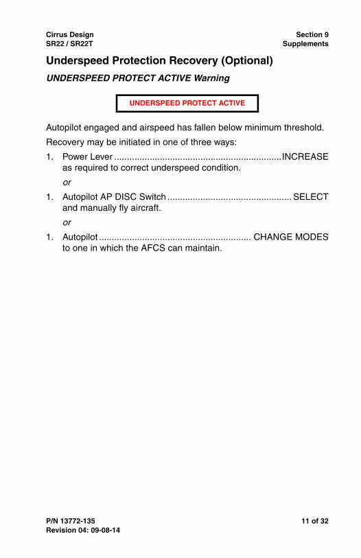
Underspeed Protection Recovery (Optional)
UNDERSPEED PROTECT ACTIVE Warning
Autopilot engaged and airspeed has fallen below minimum threshold.
Recovery may be initiated in one of three ways:
1. Power Lever ..................................................................INCREASEas required to correct underspeed condition.
or
1. Autopilot AP DISC Switch ................................................. SELECTand manually fly aircraft.
or
1. Autopilot ............................................................ CHANGE MODESto one in which the AFCS can maintain.
UNDERSPEED PROTECT ACTIVE
Revision 04: 09-08-14

12 of 32 P/N 13772-135
Section 9 Cirrus DesignSupplements SR22 / SR22T
Section 4 - Normal Procedures• Note •
Normal operating procedures for the GFC 700 AutomaticFlight Control System are described in the Cirrus PerspectivePilot’s Guide.
PreFlight Inspection
1. A self test is performed upon power application to the AFCS. Aboxed AFCS annunciator will appear on the PFD in white text on ared background, followed by a boxed PFT in black text on a whitebackground. Successful completion is identified by all ModeController annunciations illuminating for two seconds.
Before Taxiing
1. Manual Electric Trim...............................................................TEST
Press the AP DISC button down and hold while commanding trim.Trim should not operate either nose up or nose down.
2. Autopilot ..............................................ENGAGE (press AP button)
3. Autopilot Override ..................................................................TESTMove flight controls fore, aft, left and right to verify that theAutopilot can be overpowered.
4. Autopilot ........................................DISENGAGE (press AP button)
5. Trim ................................................................ SET FOR TAKEOFF
Enabling/Disabling ESP (Optional)
1. Turn the large FMS Knob to select the AUX page group
2. Turn the small FMS Knob to select the System Setup Page.
3. Press the SETUP 2 Softkey.
4. Press the FMS Knob momentarily to activate the flashing cursor.
5. Turn the large FMS Knob to highlight the ‘Status’ field in theStability & Protection Box.
6. Turn the small FMS Knob to select ‘ENABLED’ or ‘DISABLED’.
7. Press the FMS Knob momentarily to remove the flashing cursor.
Revision 04: 09-08-14

Cirrus Design Section 9SR22 / SR22T Supplements
P/N 13772-135 13 of 32
Temporary Interrupt of ESP (Optional)
Although ESP is only provided when AFCS Autopilot is disengaged,the AFCS and its servos are the source of ESP guidance. When theAP Disconnect button is pressed and held, the servos will provide noESP control force feedback. Upon release of the AP Disconnectbutton, ESP will be restored.
1. AP Disconnect ..........PRESS and HOLD until maneuver complete
Section 5 - Performance
• WARNING •
The Autopilot may not be able to maintain all selectablevertical speeds. Selecting a vertical speed that exceeds theaircraft’s available performance may cause the aircraft to stall.
If AFCS Underspeed Protection function is not installed, the Autopilotwill disconnect if the Stall Warning System is activated.
Section 6 - Weight & BalanceRefer to Section 6 - Weight and Balance of the basic POH.
Revision 04: 09-08-14

14 of 32 P/N 13772-135
Section 9 Cirrus DesignSupplements SR22 / SR22T
Section 7 - System DescriptionThis airplane is equipped with a GFC 700 - a two axis (three axisoptional), fully digital, dual channel, fail passive Automatic FlightControl System (AFCS). The system consists of the GFC 705 AFCSMode Controller, Flight Management System Keyboard, Roll Servo,Pitch Servo, Yaw Servo (optional), Integrated Avionics Units, PitchTrim Adapter, Autopilot Disconnect Switch, Take Off / Go AroundButton, Electric Pitch-Trim and Roll-Trim Hat Switch. The GFC 700AFCS with optional Yaw Damper can be divided into three primaryoperating functions:
Flight Director - The Flight Director provides pitch and roll commandsto the AFCS system and displays them on the PFD. With the FlightDirector activated, the pilot can hand-fly the aircraft to follow the pathshown by the command bars. Flight Director operation takes placewithin the #1 Integrated Avionics Unit and provides:
• Mode annunciation
• Vertical reference control
• Pitch and roll command calculation
• Pitch and roll command display
Autopilot - The Autopilot controls the aircraft pitch, roll, and if installed,yaw attitudes, while following commands received from the FlightDirector. Autopilot operation occurs within the trim servos andprovides:
• Autopilot engagement and annunciation
• Autopilot command and control
• Auto-trim operation
• Manual electric trim
• Two axis airplane control (pitch and roll), including approaches
• Level (LVL) mode engagement command of zero roll and zerovertical speed.
Optional Yaw Damper - Yaw Damper operation is provided by the yawservo and supplies:
• Yaw Damper engagement and annunciation
• Yaw axis airplane control
Revision 04: 09-08-14

Cirrus Design Section 9SR22 / SR22T Supplements
P/N 13772-135 15 of 32
Figure -1GFC 700 Automatic Flight Control System Schematic
GFC 705MODE CONTROLLER
PITCH TRIMCARTRIDGE
INTEGRATEDAVIONICS UNIT 2INTEGRATED
AVIONICS UNIT 1
MFDPFD
PITCH TRIMADAPTER
YAW SERVO(optional)
ROLL SERVO PITCH SERVO
SR22_FM09_2919
4-WAYTRIM
GO-AROUNDSWITCH
A/P DISC
Revision 04: 09-08-14

16 of 32 P/N 13772-135
Section 9 Cirrus DesignSupplements SR22 / SR22T
GFC 705 AFCS Mode Controller
The GFC 705 AFCS Mode Controller, located in the upper section ofthe center console, provides primary control of Autopilot modes and, ifinstalled, yaw damper engagement. A pitch wheel is included foradjustment of pitch mode reference. 28 VDC for GFC 705 AFCS ModeController operation is supplied through 5-amp KEYPADS / AP CTRLcircuit breaker on MAIN BUS 1. All Autopilot mode selection isperformed by using the mode select buttons and pitch wheel on thecontroller. Available functions are as follows:
HDG - Heading Button
The HDG hold button selects/deselects the Heading Select mode.Heading Select commands the Flight Director to follow the headingbug (selected with the HDG knob).
NAV - Navigation Button
The NAV button selects/deselects the Navigation mode. This provideslower gains for VOR enroute tracking and disables glideslope couplingfor localizer or back course approaches and glideslope coupling forGPS approaches. This button is also used to couple to the GPS.
APR - Approach Button
The APR button selects the Approach mode. This provides highergains for VOR approach tracking and enables glideslope coupling forILS approaches and GPS coupling for LPV (Localizer Performancewith Vertical Guidance) and LNAV +V approaches.
AP - Autopilot Button
The AP button engages/disengages the Autopilot.
LVL - Level Button
The LVL button engages the Autopilot (within the AutopilotEngagement Limits if not already engaged) and commands roll to zerobank angle and pitch to zero vertical speed. The LVL button will notengage, or will disengage, if the Stall Warning System is activated.
FD - Flight Director Button.
The FD button toggles the Flight Director activation. It turns on theFlight Director in the default pitch and roll modes if no modes werepreviously selected. Pressing the FD button with command bars inview, will deactivate the Flight Director and remove the command barsunless the Autopilot is engaged. If the Autopilot is engaged, the FDbutton is deactivated.
Revision 04: 09-08-14

Cirrus Design Section 9SR22 / SR22T Supplements
P/N 13772-135 17 of 32
YD - Yaw Damper Button (Optional)
The YD button engages/disengages the yaw damper.
• Note •
The yaw damper is automatically engaged when the Autopilotis engaged with the AP button.
UP/DN - Pitch Wheel
The Pitch UP/DN Wheel on the controller is used to change the FlightDirector pitch mode reference value. Each click of the wheel results ina step increase or decrease in the Flight Director pitch mode by theamount shown in the table below. The Pitch Wheel controls thereference for Pitch Hold (PIT), Vertical speed (VS), and IndicatedAirspeed (IAS) FD modes. The reference value is displayed next to theactive mode annunciation on the PFD. Go-Around and Glidescopemodes are not controlled by the nose Pitch Wheel, however, use of thePitch Wheel during Go-Around mode will cause reversion to Pitch Holdmode. The Pitch Wheel controls altitude reference when in altitudehold mode.
IAS - Indicated Airspeed Hold Button
The IAS button selects/deselects the Indicated Airspeed Hold mode.
ALT - Altitude Button
The ALT hold button selects/deselects the Altitude Hold mode.
VS - Vertical Speed Button
The VS button selects/deselects the Vertical Speed mode.
VNV - VNAV Button
The VNV button selects/deselects the Vertical Navigation mode.
Flight Director Mode Step Value
Default Pitch Hold (PIT) 0.50 Degree
Vertical speed (VS) 100 Feet per Minute
Indicated Airspeed (IAS) 1 Knot
Altitude Hold (ALT) 10 Feet
Revision 04: 09-08-14

18 of 32 P/N 13772-135
Section 9 Cirrus DesignSupplements SR22 / SR22T
Flight Management System Keyboard
The Flight Management System Keyboard, found in the center consolebelow the AFCS mode controller, is the primary means for data entryfor the MFD and is used to control NAV/COM Radios, transponder,and flight management system entry. Heading, course and altitudeselect are also provided.
28 VDC for Flight Management System Keyboard operation issupplied through the 5-amp KEYPADS / AP CTRL circuit breaker onMAIN BUS 1.
AFCS related functions are as follows:
HDG - Heading Knob.
The HDG knob controls the selected heading bug on the HSI portionof the PFD. It provides the reference for heading select mode. Pushingthe HDG knob synchronizes the selected heading to the currentheading.
CRS - Course Knob
The CRS knob controls the course pointer on the HSI portion of thePFD. It provides the reference for FD navigation modes when theFlight Director is selected. Pushing the CRS knob re-centers the CDIand returns the course pointer to the bearing of the active waypoint ornavigation station.
ALT SEL - Altitude Select Knob
The ALT knob controls the Selected Altitude, which is used as thereference for the altitude alerter and the altitude capture function.Pushing the ALT SEL knob synchronizes the selected altitude to thedisplayed altitude to the nearest 10 ft.
Revision 04: 09-08-14

Cirrus Design Section 9SR22 / SR22T Supplements
P/N 13772-135 19 of 32
Figure -2FMS Keyboard and GFC 705 AFCS Mode Controller
3
4 7 8 12 1311
6 9 10 14 15
HDG NAV AP LVL IAS ALT
APR FD YD VS VNV
UP
DN
Flight Management System Keyboard
GFC 705 Mode Controller
RANGE
PUSH
- +
PAN
HDG
CRS
ALT SEL
GARMIN
A B C D E F
G H I J K
L M N O P Q
R
W
S
X
T
Y
U
Z
V
SPC BKSP
1 2 3
4 5 6
7 8 9
0 +/-
EMERGCRSR/1-2PUSH
FMS/XPDRCOM/NAV
IDENT
DFLT MAPPUSH SYNC
PUSH CTR
PUSH SYNC
D
FPL
CLR
MENU
PROC
ENT
FMS XPDR
COM NAV
Legend 1. Heading Selection 2. Course Selection 3. Altitude Selection 4. Heading Select Mode 5. Navigation Mode 6. Approach Mode 7. Autopilot 8. Wings Level
1
9. Flight Director10. Yaw Damper (optional)11. Pitch Wheel12. Indicated Airspeed Hold13. Altitude Hold14. Vertical Speed Mode15. Vertical Navigation Mode
2
5
SR22_FM09_2921
Revision 04: 09-08-14

20 of 32 P/N 13772-135
Section 9 Cirrus DesignSupplements SR22 / SR22T
Roll, Pitch and Optional Yaw Servo
The Roll Servo, located below the passenger seat, the Pitch Servo,located below the baggage compartment, and the optional Yaw Servo,located in the empennage avionics bay, position the aircraft flightcontrols in response to commands generated by the IntegratedAvionics Units Autopilot calculations.
28 VDC for Roll and Pitch Servo operation is supplied through the 5-amp AP SERVOS circuit breaker on MAIN BUS 1.
28 VDC for Yaw Servo operation is supplied through the 3-amp APYAW SERVO circuit breaker on MAIN BUS 3.
Integrated Avionics Units
The Integrated Avionics Units located behind the MFD and instrumentpanel, function as the main communication hubs to the AvionicsSystem and GFC 700, linking the systems to the PFD and MFDdisplays. Each Integrated Avionics Unit receives air and attitude dataparameters from the Air Data Computer and Attitude and HeadingReference System. Each Integrated Avionics Unit contains a GPSWAAS receiver, VHF COM/NAV/GS receivers, and system integrationmicroprocessors. The AFCS function within the Integrated AvionicsUnits control the active and armed modes for the Flight Director, aswell as Autopilot engagement. The Flight Director commands for theactive modes are calculated and sent to the PFD for display and modeannunciation. The sensor data and Flight Director commands are alsosent to the servos over a common serial data bus.
28 VDC for Integrated Avionics Unit 1 operation is supplied throughthe 7.5-amp COM 1 and 5-amp GPS NAV1 circuit breakers on theESS BUS 1. 28 VDC for Integrated Avionics Unit 2 operation issupplied through the 7.5-amp COM 2 and 5-amp GPS NAV2 circuitbreakers on the MAIN BUS 2.
Autopilot Disconnect Switch
The yoke mounted Autopilot Disconnect (AP DISC) Switch disengagesthe Autopilot and may also be used to mute the aural alert associatedwith an Autopilot Disconnect.
For ESP equipped aircraft, the Autopilot Disconnect Switch will alsotemporarily suspend the servo's from providing ESP correction forces,thus having an "interrupt" function. This may be useful to alleviate
Revision 04: 09-08-14

Cirrus Design Section 9SR22 / SR22T Supplements
P/N 13772-135 21 of 32
control forces if intentional maneuvers are necessary beyond ESP'sengagement threshold (i.e., isolated training maneuvers).
Take Off / Go Around Button
The remote TO/GA switch, located on the left side of the power lever,selects the Takeoff or Go Around mode on the Flight Director. Whenthe aircraft is on the ground, pressing the TO/GA switch engages theFlight Director command bars in Takeoff (TO) mode. When the aircraftis in the air, pressing the TO/GA switch engages the Flight Directorcommand bars in Go Around (GA) mode and cancels all armed modesexcept ALT ARM (ALTS).
• Note •
For aircraft without USP, selection of the TO/GA switch willalso disengage the autopilot.
For aircraft with USP, selection of TO/GA switch will notchange autopilot engagement (i.e., if initially engaged,autopilot will remain engaged; if initially not engaged, autopilotwill remain not engaged).
After TO/GA engagement, other roll modes may be selected andAutopilot engagement is allowed. However, an attempt to modify thepitch attitude with the Pitch Wheel will result in a reversion to PITmode. Additionally, if in Approach mode, pressing the TO/GA switchresumes automatic sequencing of waypoints by deactivating the“SUSP” mode.
For aircraft with optional USP function, if power is insufficient tomaintain go-around attitude, the Autopilot will enter UnderspeedProtection Mode.
Pitch Trim Adapter
The Pitch Trim Adapter, located below the passenger seat, takes inputfrom the trim switches, Integrated Avionics Units, and the pitch servosto allow the GFC 700 to drive the pitch trim cartridge.
28 VDC for Pitch Trim Adapter operation is supplied through the 2-ampPITCH TRIM circuit breaker on Main Bus #1.
Electric Pitch/Roll-Trim Hat Switch
The yoke mounted Electric Pitch Trim and Roll Trim Hat Switch allowsthe pilot to manually adjust aircraft trim when the Autopilot is notengaged.
Revision 04: 09-08-14

22 of 32 P/N 13772-135
Section 9 Cirrus DesignSupplements SR22 / SR22T
Electronic Stability and Protection (Optional)
When installed, Electronic Stability and Protection (ESP) assists thepilot in maintaining the airplane in a safe flight condition. Through theuse of the GFC 700 AFCS sensors, processors, and servos, ESPprovides control force feedback, i.e. a “soft barrier”, to maintain theaircraft within the pitch, roll, and airspeed flight envelope byautomatically engaging one or more servos when the aircraft is nearthe defined operating limit.
This feature is only active when in flight and the GFC 700 Autopilot isoff. The ESP engagement envelope is the same as the Autopilotengagement envelope and is not provided beyond the Autopilotengagement limits.
The pilot can interrupt ESP by pressing and holding the AutopilotDisconnect (AP DISC) button. If frequent maneuvers are necessarybeyond the engagement threshold, such as commercial pilot training,the system can be disabled from AUX/SETUP 2 page. Disabling willcause the ESP OFF advisory to annunciate. The system can be re-enabled from the same page, or is automatically re-enabled at the nextsystem power-up.
Pitch and Roll Modes
When the aircraft reaches the pitch and/or roll engagement limit, thesystem commands the servos to apply a supplemental stick force backtoward the nominal attitude range. If the aircraft continues to pitch and/or roll away from the nominal attitude range, stick forces will increasewith increasing attitude deviation until the maximum Autopilotengagement limits are reached - at which point ESP will disengage.
ESP attempts to return the aircraft to the nominal attitude range not toa specific attitude. As the attitude returns to the nominal range, thestick forces and attitude rate change are reduced until the aircraftreaches the disengagement threshold and ESP becomes inactive. Thedisengagement threshold is sized so that the transition from ESPbeing active to being inactive is transparent to the pilot.
Roll protection engagement limits are annunciated on the PFD asdouble ticks at 45° roll attitude. If the aircraft exceeds 45° roll attitudeESP becomes engaged and these indicators migrate to 30° rollattitude denoting the disengagement threshold - the point at whichstick forces will be removed. No PFD annunciation is provided duringpitch ESP engagement.
Revision 04: 09-08-14

Cirrus Design Section 9SR22 / SR22T Supplements
P/N 13772-135 23 of 32
Roll Protection Limits:
Engagement Limit: .....................................................................45°
Maximum Stick Force attained at...............................................50°
Disengagement Threshold (Zero Stick Force) ...........................30°
High Pitch Protection Limits
Engagement Limit: ................................................................+17.5°
Maximum Stick Force attained at:.........................................+22.5°
Disengagement Threshold (Zero Stick Force): .....................+12.5°
Always Protected
Only Protected after cross-ing turn-on threshold
Bank Angle0° 30° 45° 60° 75° 90°15°
Win
gs L
evel
Sup
plem
enta
l Stic
k F
orce
SR
22_F
M09
_339
9
Nose Up Pitch Angle0° 10° 15° 20° 25°5°
Nos
e D
own
Sup
plem
enta
l Stic
k F
orce Always Protected
Only Protected after cross-ing turn-on threshold
SR
22_F
M09
_340
3
Revision 04: 09-08-14

24 of 32 P/N 13772-135
Section 9 Cirrus DesignSupplements SR22 / SR22T
Low Pitch Protection Limits
Engagement Limit: ................................................................ -15.5°
Maximum Stick Force attained at: ......................................... -20.5°
Disengagement Threshold (Zero Stick Force): ..................... -10.5°
High Airspeed Mode
To protect against an overspeed condition, the High Airspeed Modeuses engagement limits, thresholds, and stick forces similar to thoseused for the pitch and roll modes, but is instead triggered by airspeedand controlled by pitch attitude. When the aircraft reaches the ESPengagement limit, the system commands the pitch servo to apply asupplemental stick force back toward the nominal airspeed range.
• Note •
For turbocharged equipped aircraft, Vne reduces above17,500 ft PA to follow a Mach limit of 0.42.
At high altitudes Mach number determines the threshold.
Nose Down Pitch Angle-0° -10° -15° -20° -25°-5°
Nos
e U
p S
uppl
emen
tal S
tick
For
ce Always Protected
Only Protected after cross-ing turn-on threshold
SR
22_F
M09
_342
6
Revision 04: 09-08-14

Cirrus Design Section 9SR22 / SR22T Supplements
P/N 13772-135 25 of 32
High Airspeed Protection Limits - Below 17,500 ft PA
Engagement Limit: ...........................................................200 KIAS
Maximum Stick Force attained at:....................................205 KIAS
Disengagement Threshold (Zero Stick Force): ................190 KIAS
High Airspeed Protection Limits - Above 17,500 ft PA
Engagement Limit: ....................................................... Mach 0.419
Maximum Stick Force attained at:................................ Mach 0.430
Disengagement Threshold (Zero Stick Force): ............ Mach 0.399
205Indicated Airspeed (KIAS)
180 190 195 200 210185
Nos
e U
p S
uppl
emen
tal S
tick
For
ceAlways Protected
Only Protected after cross-ing turn-on threshold
SR
22_F
M09
_340
5
Always Protected
Only Protected after cross-ing turn-on threshold
0.4 0.41 0.42Mach Number
0.395 0.415 0.425 0.43 0.4350.405
Nos
e U
p S
uppl
emen
tal S
tick
For
ce
SR
22_F
M09
_342
8
Revision 04: 09-08-14

26 of 32 P/N 13772-135
Section 9 Cirrus DesignSupplements SR22 / SR22T
Serials w/ Discrete-Triggered Low Speed Mode (Optional)
To protect against an impending stall, the Discrete-Triggered LowSpeed Mode uses stick forces, similar to those used for the pitch androll modes, to control the pitch attitude. These stick forces aretriggered by the stall warning system. Upon stall warning systemactivation, the system commands the pitch servo to apply a nose-down supplemental force. The maximum stick force is attainedapproximately 1.5 seconds after the stall warning signal is activated,and is maintained as long as the stall warning system is active. If thestall warning system becomes inactive, the supplemental force issmoothly removed over approximately 2 seconds.
Low Speed Protection
Engagement Limit: ..................................................... Stall warning
Maximum Stick Force attained at: .. 1.5 seconds after stall warning
Disengagement Threshold: .....................Stall warning deactivated
Zero Stick Force: ............ 2 seconds after stall warning deactivated
Underspeed Protection Mode (Optional)
When installed, to discourage aircraft operation below minimumestablished airspeeds the AFCS will automatically enter UnderspeedProtection Mode when the Autopilot is engaged and airspeed fallsbelow the minimum threshold. If aircraft stall warning system is notoperational, autopilot underspeed protections that depend on thatsystem will also not be functional (affects altitude critical modes only:ALT, GS, GP, TO, and GA).
ESP Force
Stall Warning
Time (sec)0 4 6 8 102
Nos
e D
own
For
ce S
uppl
emen
t
SR
22_F
M09
_365
9
Revision 04: 09-08-14
Cirrus Design Section 9SR22 / SR22T Supplements
P/N 13772-135 27 of 32
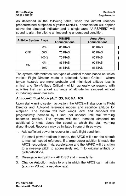
As described in the following table, when the aircraft reachespredetermined airspeeds a yellow MINSPD annunciation will appearabove the airspeed indicator and a single aural “AIRSPEED” willsound to alert the pilot to an impending underspeed condition.
The system differentiates two types of vertical modes based on whichvertical Flight Director mode is selected; Altitude-Critical - whereterrain hazards are more probable and minimized altitude loss iscritical and Non-Altitude Critical - which generally correspond withactivities that can afford exchange of altitude for airspeed withoutintroducing terrain hazards.
Altitude-Critical Mode (ALT, GS, GP, GA, TO)
Upon stall warning system activation, the AFCS will abandon its FlightDirector and Autopilot reference modes and sacrifice altitude forairspeed. The system will hold wings level and airspeed willprogressively increase by 1 knot per second until stall warningbecomes inactive. The system will then increase airspeed anadditional 2 knots above the speed at which the stall warningdiscontinued. Recovery may be initiated in one of three ways:
1. Add sufficient power to recover to a safe flight condition.
If a small power addition is made, the AFCS will pitch the aircraftto maintain speed reference. If a large power addition is made theAFCS recognizes it via acceleration and the AP/FD will transitionto a nose-up pitch to aggressively return to original altitude orglidepath/slope.
2. Disengage Autopilot via AP DISC and manually fly.
3. Change Autopilot modes to one in which the AFCS can maintain(such as VS with a negative rate).
Anti-Ice System FlapsMINSPD
AnnunciationsAural Alert
Annunciations
OFF
0% 80 KIAS 85 KIAS
50% 76 KIAS 80 KIAS
100% 70 KIAS 80 KIAS
ON0% 85 KIAS 90 KIAS
50% 81 KIAS 85 KIAS
Revision 04: 09-08-14

28 of 32 P/N 13772-135
Section 9 Cirrus DesignSupplements SR22 / SR22T
Non-Altitude Critical Mode (VS, PIT, VNAV, LVL, IAS)
For all non-altitude critical modes the Autopilot will maintain its originalreference (VS, PIT, etc...) until airspeed decays to a minimum airspeed(MINSPD). Crew alert and annunciation during a non-altitude criticalunderspeed event are similar to an altitude-critical event, except that;
• Stall warning may not be active. Depending on load tolerances,the AP/FD may reach the minimum airspeed reference and takeunderspeed corrective action before stall warning occurs. If stallwarning does coincide or precede the aircraft reaching itsminimum airspeed reference, it has no influence - only airspeedaffects the AP/FD in non-altitude critical events.
• The originally selected lateral mode remains active.
Upon reaching minimum airspeed, the AFCS will abandon its FlightDirector and Autopilot reference modes and maintain this airspeeduntil recovery. As with altitude-critical modes, available options forrecovery are add power, decouple/manually fly, or change Autopilotmodes.
When adding power, unlike the altitude-critical modes, which performsan aggressive recovery, the AP/FD will maintain MINSPD until theoriginal reference can be maintained. Non-altitude critical modes willmaintain the originally selected lateral mode (HDG, NAV, etc...).
Coupled Go-Around
Airplanes equipped with Underspeed Protection Mode are capable offlying fully coupled go-around maneuvers. Pressing the GA button onthe throttle will not disengage the Autopilot. Instead, the Autopilot willattempt to capture and track the Flight Director command bars. Ifinsufficient airplane performance is available to follow the commands,the AFCS will enter Altitude-Critical Mode when the stall warningsounds.
Revision 04: 09-08-14

Cirrus Design Section 9SR22 / SR22T Supplements
P/N 13772-135 29 of 32
Hypoxia Detection and Automatic Descent (Optional)
When installed, the AFCS Hypoxia Detection and Automatic Descentfunction monitors pilot inputs to the Integrated Avionics System toidentify if a pilot has become incapacitated due to hypoxia, and upondetermination, automatically descends to a lower altitude where pilotrecovery is more probable. The feature is only available when the GFC700 Autopilot is engaged and the aircraft is above 14,900 ft PA.
Mode of Operation
Pilot interaction with the Integrated Avionics System is monitored bydetecting key presses and turns of the knobs. If the pilot has not madea system interaction within a defined interval - based on altitude andtime of useful consciousness - the AFCS prompts the pilot for aresponse with an ARE YOU ALERT? CAS Advisory.
If no pilot response to the Advisory is detected, after one minute theAFCS annunciates an HYPOXIA ALERT Caution and a double chimeaural alert.
After one minute, if no response to the Caution is detected the systemannunciates an AUTO DESCENT Warning and continuous auralwarning tone.
Lack of response after one minute of Warning annunciation isconsidered evidence of pilot incapacitation. The AFCS willautomatically engage emergency descent mode (EDM) as follows:
1. EDM will annunciate in the AFCS status window.
2. The altitude bug will be automatically set to 14,000 ft indicated.
3. The airspeed bug will be set to the maximum commandableAutopilot speed - i.e., the lesser of 185 KIAS or Mach 0.420.
4. The Autopilot vertical mode will change to IAS, and initiate adescent to intercept 14,000 ft indicated.
Once descent begins only Autopilot Disconnect (AP DISC) willinterrupt this process. Autopilot lateral mode remains unchangedthroughout the descent and the aircraft will continue on its previouslyselected course or heading. After reaching 14,000 ft indicated, theaircraft will maintain this flight level for 4 additional minutes. If the pilotdoes not acknowledge the Warning and resume control of the aircraft,the AFCS will automatically perform a secondary descent to 12,500 ftPA at 185 KIAS. An altitude of 12,500 ft PA will be maintained if thepilot remains unresponsive
Revision 04: 09-08-14

30 of 32 P/N 13772-135
Section 9 Cirrus DesignSupplements SR22 / SR22T
Annunciation System
• Note •Refer to the Cirrus Perspective Pilot’s Guide for a detaileddescription of the annunciator system and all warnings,cautions and advisories.
Crew Alerting System
AFCS alerts are displayed in the Crew Alerting System (CAS) windowlocated to the right of the altimeter and VSI. AFCS annunciations aregrouped by criticality and sorted by order of appearance with the mostrecent message on top. The color of the message text is based on itsurgency and required action:
• Warning (red) – Immediate crew awareness and action required.
• Caution (yellow) – Immediate crew awareness and futurecorrective action required.
• Advisory (white) – Crew awareness required and subsequentaction may be required.
In combination with the CAS Window, the system issues an audio alertwhen specific system conditions are meet and an expandeddescription of the condition is displayed in the Alerts Window locatedin the lower RH corner of the PFD.
• Note •
For specific pilot actions in response to AFCS alerts, refer toSection 3A - Abnormal Procedures.
AFCS Status Box and Mode Annunciation
Flight Director mode annunciations are displayed on the PFD whenthe Flight Director is active. Flight director selection and Autopilot andyaw damper statuses are shown in the center of the AFCS Status Box.Lateral Flight Director modes are displayed on the left and vertical onthe right. Armed modes are displayed in white and active in green.
AFCS status annunciations are displayed on the PFD above theAirspeed and Attitude indicators. Only one annunciation may occur ata time. Messages are prioritized by criticality.
Revision 04: Pending

Cirrus Design Section 9SR22 / SR22T Supplements
P/N 13772-135 31 of 32
Section 8 – Handling, Service, & MaintenanceNo Change.
Section 10 – Safety InformationNo Change.
Revision 04: Pending

32 of 32 P/N 13772-135
Section 9 Cirrus DesignSupplements SR22 / SR22T
Revision 04: Pending
Intentionally Left Blank


