PILOT’S GUIDE - Flugschule Grenchen - Flugschule … is designed for simple and intuitive...
42
Meet REV. G January 6, 2017 Manual Number 9017846 MD302 Standby Attitude Module PILOT’S GUIDE
Transcript of PILOT’S GUIDE - Flugschule Grenchen - Flugschule … is designed for simple and intuitive...

Meet
REV. G January 6, 2017 Manual Number 9017846
MD302 Standby Attitude Module
PILOT’S GUIDE
REV. G January 6, 2017 Manual Number 9017846
FORWARD
This manual contains information regarding the use and interpretation of information presented to the pilot and crew during normal and emergency operation of SAM — the MD302 Standby Attitude Module. Operational instructions are intended for persons who operate aircraft in accordance with applicable Federal Aviation Regulations (Title 14 CFR).
We welcome your comments concerning our product and this manual. When reporting a specific problem, please describe it briefly and include the manual part number, the paragraph or image number and page number.
Please e-mail or send comments and technical questions to:
Mid-Continent Instruments and AvionicsAttn: Technical Publications9400 East 34th Street North Wichita, Kansas 67226 USAE-mail: [email protected]

TABLE OF CONTENTS
IMPORTANT: Read this entire guide prior to operating SAM — the MD302
Standby Attitude Module — in flight.
PAGE
USER INTERFACE 1
PRE-FLIGHT MODE 2
FLIGHT MODE 3
Attitude Operation 4
Slip Operation 7
Heading Operation 8
Altitude Operation 10
Airspeed Operation 14
Menu Operation 17
OPTIONS MENU 18
ALT Units 19
BARO Units 20
Attitude Symbol 21
ATT Mask 22
ALT Trend 23
INFO 24
Review Configuration 25
Battery INFO 26
Exit Menu 27
Power OFF 28
Brightness Adjustment 29
EMERGENCY OPERATION 30
In Flight 30
On the Ground 32
ALERTS AND ANNUNCIATIONS 33
SERVICE REMINDER 35
PRODUCT SPECIFICATIONS 39
LIMITED WARRANTY 40
PRODUCT REGISTRATION 41

SAM is designed for simple and intuitive operation. The User Interface provides quick interpretation of the flight information displayed.
The central Control Knob can be located at the bottom-center, middle-left or middle-right of the unit bezel depending on the installation orientation. This is the only user interface device on the unit.
The Control Knob has two functions: Push and Turn.
The Control Knob provides 16-detents per revolution and typically changes the information it is controlling on the display one unit per detent or click.
The Push function is used to select the highlighted option in a menu or to enter and exit menus and control functions. The Push function can also perform certain operations with a push-and-hold action.
USER INTERFACE
REV. G January 6, 2017 Manual Number 9017846 1

REV. G January 6, 2017 Manual Number 90178462
In Pre-flight Mode, power is applied to the unit and the Introduction Screen appears during startup (Image 1).
During Pre-flight Mode, the Introduction Screen will be displayed while the unit conducts an initial Power-up Built-in Test (PBIT) of the system to validate operational readiness. This includes, among others, a battery capacity measurement, an internal test to verify software and memory, and confirmation that the internal settings and identification of the unit match the Configuration Module installed in the aircraft cable harness.
The Introduction Screen will be displayed for approximately five seconds and will transition to Flight Mode when complete.
PRE-FLIGHT MODE
PRE-FLIGHT MODEINTRODUCTION SCREEN
Image 1

In Flight Mode, theunit operates normally by displaying six functions:
Attitude, Altitude, Airspeed, Slip, Vertical Trend, and Heading Information (Images 2, 3).
FLIGHT MODE
FLIGHT MODEHORIZONTAL ORIENTATION
Image 2
REV. G January 6, 2017 Manual Number 9017846 3
Image 3
FLIGHT MODEVERTICAL ORIENTATION
Flight Mode / ATTITUDE OPERATION
REV. G January 6, 2017 Manual Number 90178464
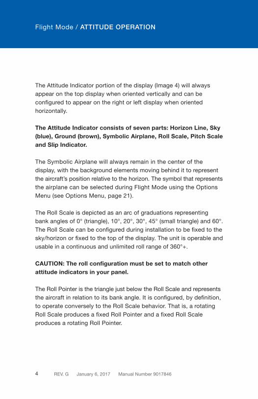
The Attitude Indicator portion of the display (Image 4) will always appear on the top display when oriented vertically and can be configured to appear on the right or left display when oriented horizontally.
The Attitude Indicator consists of seven parts: Horizon Line, Sky (blue), Ground (brown), Symbolic Airplane, Roll Scale, Pitch Scale and Slip Indicator.
The Symbolic Airplane will always remain in the center of the display, with the background elements moving behind it to represent the aircraft’s position relative to the horizon. The symbol that represents the airplane can be selected during Flight Mode using the Options Menu (see Options Menu, page 21).
The Roll Scale is depicted as an arc of graduations representing bank angles of 0° (triangle), 10°, 20°, 30°, 45° (small triangle) and 60°. The Roll Scale can be configured during installation to be fixed to the sky/horizon or fixed to the top of the display. The unit is operable and usable in a continuous and unlimited roll range of 360°+.
CAUTION: The roll configuration must be set to match other attitude indicators in your panel.
The Roll Pointer is the triangle just below the Roll Scale and represents the aircraft in relation to its bank angle. It is configured, by definition, to operate conversely to the Roll Scale behavior. That is, a rotating Roll Scale produces a fixed Roll Pointer and a fixed Roll Scale produces a rotating Roll Pointer.

ATTITUDE OPERATION
Flight Mode / ATTITUDE OPERATION
REV. G January 6, 2017 Manual Number 9017846 5
Image 4
Roll/Bank Scale
Symbolic Airplane
Pitch Scale
Horizon LineSlip Indicator
The Pitch Scale is depicted as a series of graduations representing pitch angles every 5°, with every 10° graduation being wider and numbered. The unit is operable and usable in a continuous and unlimited pitch range of 360°+.

Flight Mode / ATTITUDE OPERATION
ATTITUDE OPERATION
This image demonstrates 50° pitch up and 18° left turn. Red chevrons point to the horizon line.
Image 5
REV. G January 6, 2017 Manual Number 90178466
30
30
60
60
50
50
40
40
A series of chevrons (^) will appear overlaid on the Pitch Scale at attitudes greater than ± 45°. This is to indicate to the pilot the direction of the horizon for quick reference when in an unusual pitch attitude (Image 5). The chevrons always point toward the horizon line.

The Slip Indicator portion of the display will appear at the bottom of the Attitude Display (Image 5). If Heading Operation is enabled, the Slip Indicator will appear to the left and above the Heading Window in horizontal orientation, and directly above the Heading Window in vertical orientation (Image 6).
The Slip Indicator is represented by a shaded translucent background with two white lines around center and a white ball. When the ball is maintained between the vertical lines during banking maneuvers, the turn is considered “coordinated” without slip.
The Slip Indicator’s background becomes semi-transparent if the Roll Scale or Roll Pointer pass behind the indicator. All other elements remain visible.
Flight Mode / SLIP OPERATION
REV. G January 6, 2017 Manual Number 9017846 7

HEADING OPERATION
Flight Mode / HEADING OPERATION
Image 6
Roll/Bank Scale
Symbolic Airplane Heading Scale
Pitch Scale Horizon Line
Heading WindowSlip Indicator
Heading Operation can be configured during installation. The heading information is comprised of a window showing the current heading and a moving scale located along the bottom of the display (Image 6). The Heading Scale is depicted as a series of graduations every 10° with numbers every 30°, and letters for each cardinal heading.
REV. G January 6, 2017 Manual Number 90178468

ARINC DATA LOSS
The Heading data is received directly from ARINC input and displayed without reprocessing. If ARINC input data is lost, the display will read “---” (Image 7).
Image 7
Flight Mode / HEADING OPERATION
REV. G January 6, 2017 Manual Number 9017846 9
ARINC data loss shown below.
HEADING OPERATION

Flight Mode / ALTITUDE OPERATION
The Altimeter Indicator portion of the display will always appear on the bottom display when oriented vertically and can be configured to appear on the right or left display when oriented horizontally (Image 8).
The Altimeter consists of four parts: Altitude Window, Altitude Scale, Barometric Setting Window and optional Altitude/Vertical Trend Bar.
The Altitude Window displays the current, barometric corrected altitude. The digits of the display are in increments of twenty and the window is expanded over this portion of the number to display a minimum spread of forty units. The numbers will ‘roll’ or scroll to assist in quick reference to the increasing or decreasing nature of the aircraft’s altitude. The hundreds, thousands and ten-thousands digits appear to the left of the tens digits with the thousands and ten-thousand digits slightly larger than the others. The Altitude Pointer (triangle) to the right of the window points to the associated position on the Altitude Scale of the current altitude. Altitude units of measure appear below the Altitude Window and can be changed during Flight Mode using the Options Menu (see Options Menu, page 19). The pilot may select feet or meters.
The Altitude Scale is positioned vertically along the right margin of the display. The current altitude is always in the middle of the scale and indicated by the Altitude Pointer on the right side of the Altitude Window. The scale has numeric indications every one-hundred units with minor graduations every fifty units and sub-graduations every twenty-five units. In horizontal installations, the scale spans approximately 400 units from top to bottom. In vertical installations, the scale spans approximately 500 units from top to bottom. The scale will ‘roll’ or scroll to assist in quick reference to the increasing
REV. G January 6, 2017 Manual Number 901784610

Flight Mode / ALTITUDE OPERATION
REV. G January 6, 2017 Manual Number 9017846 11
Altitude display shown below.
ALTITUDE OPERATION
Image 8
Altitude Scale
Altitude/Vertical Trend Bar
Altitude Window/PointerAltitude Units of Measure
Barometric Setting Window

REV. G January 6, 2017 Manual Number 901784612
Flight Mode / ALTITUDE OPERATION
or decreasing nature of the aircraft’s altitude. The Barometric Window shows the currently set barometric pressure. It is identified by the abbreviation BARO and is located at the top center of the Airspeed/Altitude Display. Setting the current barometric pressure compensates the altitude for the appropriate environmental conditions.
The barometric setting can be adjusted by turning the Control Knob while in Flight Mode. When adjusting the barometric pressure the digits will turn green (Image 9). When finished setting the pressure the digits will return to their original color. Barometric pressure units can be selected during Flight Mode using the Options Menu (see Options Menu, page 20). Note: If the unit is installed to receive ARINC data from the Primary Flight Display (PFD), the BARO value will automatically synchronize. When the two are synchronized two arrows will appear on either side of BARO (Image 10). Manually changing the MD302 barometric setting will override the external source.
The Altitude Trend Bar is located along the right margin of the Altitude Display. This feature can be turned ON or OFF using the Options Menu (see Options Menu, page 23). The Altitude Trend Bar is magenta in color and originates at the current altitude on the Altitude Scale — always from the middle of the display, directly across from the Altitude Pointer. The height of the Trend Bar, above or below the current altitude, indicates the altitude of the aircraft on the Altitude Scale if the current vertical speed or ‘altitude trend’ is maintained over a period of six seconds. For example, as seen in Image 9, the current altitude is approximately 2,420 feet. The Trend Bar is at approximately 2,470 feet, indicating that the aircraft’s altitude will be 2,470 feet in six seconds if the current vertical speed or climb is maintained constant. The length of the Trend Bar will increase with increased dive or climb rates and approach zero or disappear entirely as the vertical speed reaches zero in level flight.

Flight Mode / ALTITUDE OPERATION
REV. G January 6, 2017 Manual Number 9017846 13
Image 10
Two arrows appear on either side of BARO when synchronized.
Image 9
The Barometric Setting will turn green during adjustment.

REV. G January 6, 2017 Manual Number 901784614
Flight Mode / AIRSPEED OPERATION
The Airspeed Indicator portion of the display will always appear on the bottom display when oriented vertically and can be configured to appear on the right or left display when oriented horizontally (Image 11).
The Airspeed Indicator Display consists of three parts: Airspeed Window, Airspeed Scale and Airspeed Limitations or Range Markings.
The Airspeed Window displays the current Indicated Airspeed (IAS). The digits of the display are enlarged for visibility and increment by one unit. The units will ‘roll’ or scroll to assist in quick reference as to the increasing or decreasing nature of the aircraft’s airspeed. The Airspeed Pointer (triangle) to the left of the window points to the associated position on the Airspeed Scale of the current airspeed. Airspeed units are available in Knots, KPH (kilometers per hour) or MPH (miles per hour). The unit of measure appears below the airspeed window and can be selected during installation in the Configuration Mode only. This selection is not available in Flight Mode.
The Airspeed Scale is positioned vertically along the left margin of the display. The current airspeed is always in the middle of the scale and indicated by the Airspeed Pointer on the left side of the Airspeed Window. The Airspeed Scale has numeric indications every ten or twenty units depending on the unit of measure selected. Minor graduations appear every five or ten units, respectively. In horizontal installations, the scale spans approximately 50 or 100 units from top to bottom, depending on the unit of measure. In vertical installations, the scale spans approximately 80 or 160 units from top to bottom, depending on the unit of measure. The Airspeed Scale will ‘roll’ or scroll to assist in quick reference as to the increasing or decreasing nature of the aircraft’s airspeed.

Flight Mode / AIRSPEED OPERATION
Image 11
Range Markings
Airspeed Scale
AirspeedWindow/Pointer
Airspeed Units
Airspeed display shown below.
AIRSPEED OPERATION
REV. G January 6, 2017 Manual Number 9017846 15

Flight Mode / AIRSPEED OPERATION
The Airspeed Limitations, also known as “V-speeds” or Range Marks, are indicated with colored range marking bands placed vertically along the left margin next to the Airspeed Scale. The colors and values of each bar can be set during installation in Configuration Mode by the installer only. This setting is not available in Flight Mode. Colors must be selected based on industry-defined colors and V-speed limits as defined by the aircraft’s specific Pilot’s Operating Handbook (POH). Range markings are represented by full-width bars, half-width bars and/or radial marks. A traditional ‘barber pole’ or ‘barber pole’ radial may also be displayed if the aircraft requires and provides the appropriate Vne, Vmo and/or Mmo values.
REV. G January 6, 2017 Manual Number 901784616
REV. G January 6, 2017 Manual Number 9017846 17
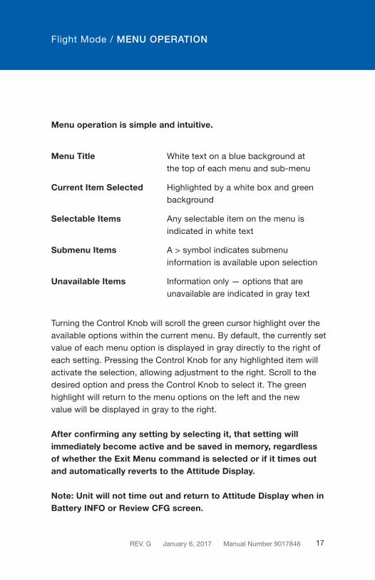
Menu operation is simple and intuitive.
Menu Title White text on a blue background at the top of each menu and sub-menu
Current Item Selected Highlighted by a white box and green background
Selectable Items Any selectable item on the menu is indicated in white text
Submenu Items A > symbol indicates submenu information is available upon selection
Unavailable Items Information only — options that are unavailable are indicated in gray text
Turning the Control Knob will scroll the green cursor highlight over the available options within the current menu. By default, the currently set value of each menu option is displayed in gray directly to the right of each setting. Pressing the Control Knob for any highlighted item will activate the selection, allowing adjustment to the right. Scroll to the desired option and press the Control Knob to select it. The green highlight will return to the menu options on the left and the new value will be displayed in gray to the right.
After confirming any setting by selecting it, that setting will immediately become active and be saved in memory, regardless of whether the Exit Menu command is selected or if it times out and automatically reverts to the Attitude Display.
Note: Unit will not time out and return to Attitude Display when in Battery INFO or Review CFG screen.
Flight Mode / MENU OPERATION

REV. G January 6, 2017 Manual Number 901784618
OPTIONS MENU
While in Flight Mode, the Options Menu is available to the pilot or cockpit crew members. It offers multiple selections that are available during flight and do not affect the aircraft-specific configuration of the unit. Options are provided for convenience,preference, or potentially necessary in-flight adjustments (Image 12).
The Options Menu can be accessed by pushing and holding the Control Knob for approximately two seconds.
The brightness adjustment bar will appear briefly before the menu is visible. The menu will appear in place of the Attitude Display and will revert to the active Attitude Display if no activity occurs for ten seconds.
The Options Menu root menu includes: ALT Units, BARO Units, Symbol, ATT Mask, ALT Trend, INFO, Exit Menu and Power OFF.
OPTIONS MENU
Image 12
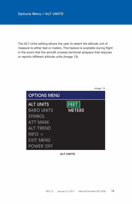
Options Menu / ALT UNITS
The ALT Units setting allows the user to select the altitude unit of measure to either feet or meters. This feature is available during flight in the event that the aircraft crosses territorial airspace that requires or reports different altitude units (Image 13).
ALT UNITS
Image 13
REV. G January 6, 2017 Manual Number 9017846 19

Options Menu / BARO UNITS
The BARO Units setting allows the user to select the altitude baro-metric adjustment unit of measure to either inHg (inches of mercury) or MBAR (millibars). This feature is available during flight in the event that the aircraft crosses territorial airspace that requires or reports different barometric pressure units (Image 14).
BARO UNITS
Image 14
REV. G January 6, 2017 Manual Number 901784620
Options Menu / ATTITUDE SYMBOL
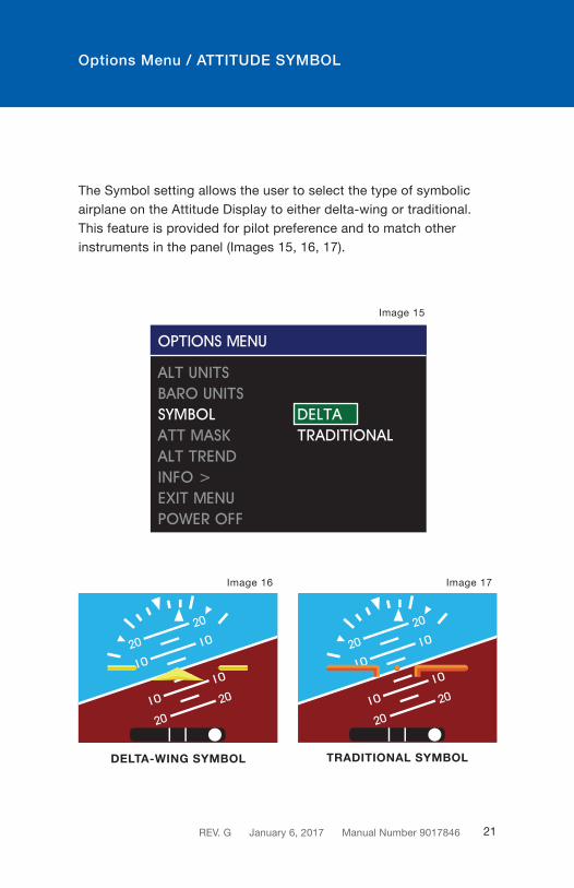
The Symbol setting allows the user to select the type of symbolic airplane on the Attitude Display to either delta-wing or traditional. This feature is provided for pilot preference and to match other instruments in the panel (Images 15, 16, 17).
DELTA-WING SYMBOL TRADITIONAL SYMBOL
Image 15
REV. G January 6, 2017 Manual Number 9017846 21
Image 16 Image 17

Options Menu / ATT MASK
The ATT Mask setting allows the user to turn the Attitude Mask ON or OFF. The Attitude Mask provides gradient dimming of the corners of the Attitude Display to give the aesthetic look of a round instrument (Images 18, 19, 20).
ATT MASK ON
Image 20
ATT MASK OFF
Image 19
Image 18
REV. G January 6, 2017 Manual Number 901784622
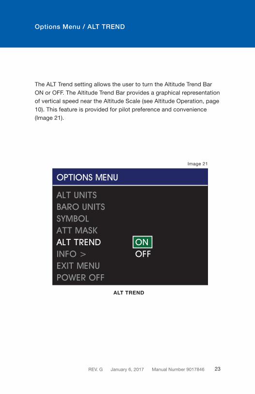
The ALT Trend setting allows the user to turn the Altitude Trend Bar ON or OFF. The Altitude Trend Bar provides a graphical representation of vertical speed near the Altitude Scale (see Altitude Operation, page 10). This feature is provided for pilot preference and convenience (Image 21).
Options Menu / ALT TREND
ALT TREND
Image 21
REV. G January 6, 2017 Manual Number 9017846 23

Options Menu / INFO
REV. G January 6, 2017 Manual Number 901784624
The INFO submenu is found within the Options Menu (Image 22). It offers multiple selections that are available during Flight Mode that do not affect the aircraft-specific configuration of the unit. The options available allow the user to access the Review Configuration (Review CFG) and Battery INFO screens (Image 23).
Image 22
Image 23

Options Menu / INFO / REVIEW CONFIGURATION
The Review CFG selection (Image 23) allows the user to review all of the values saved in unit memory previously set in Configuration Mode during installation or maintenance. There are no selectable options and this feature provides a view-only verification of information. When selected, the Review CFG screen will appear and allow the user to scroll through all of the configuration values (Image 24). Push the Control Knob to return to the INFO submenu.
REVIEW CONFIG
REV. G January 6, 2017 Manual Number 9017846 25
Image 24
Options Menu / INFO / BATTERY INFO
BATTERY INFO
Image 25
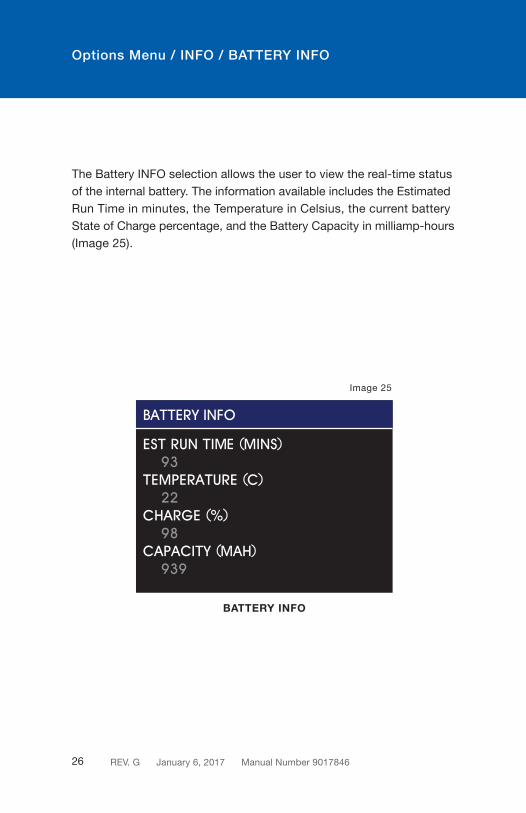
The Battery INFO selection allows the user to view the real-time status of the internal battery. The information available includes the Estimated Run Time in minutes, the Temperature in Celsius, the current battery State of Charge percentage, and the Battery Capacity in milliamp-hours (Image 25).
REV. G January 6, 2017 Manual Number 901784626
Options Menu / EXIT MENU
EXIT MENU
Image 26
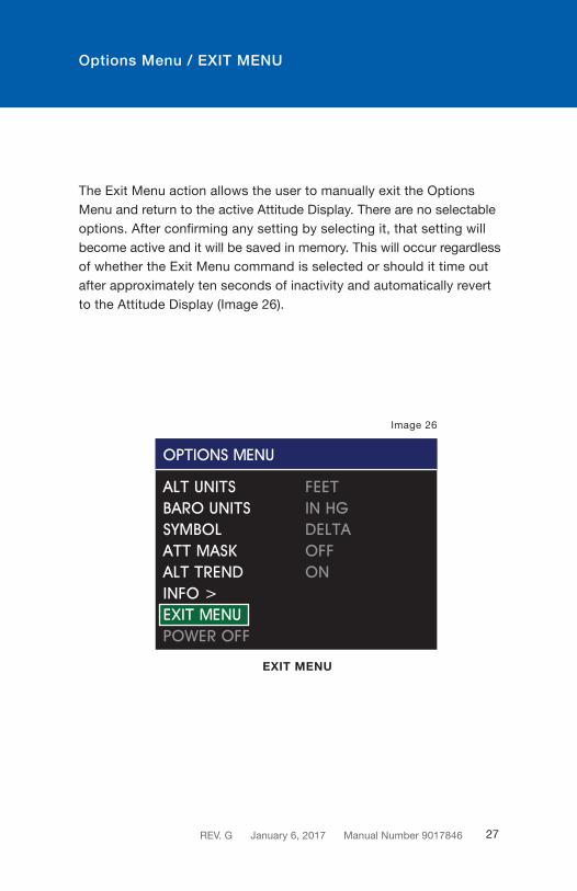
The Exit Menu action allows the user to manually exit the Options Menu and return to the active Attitude Display. There are no selectable options. After confirming any setting by selecting it, that setting will become active and it will be saved in memory. This will occur regardless of whether the Exit Menu command is selected or should it time out after approximately ten seconds of inactivity and automatically revert to the Attitude Display (Image 26).
REV. G January 6, 2017 Manual Number 9017846 27

Options Menu / POWER OFF
The Power OFF action allows the user to immediately turn the unit OFF when it is operating on its internal battery and there is no airspeed (<30 kts) detected. This item is typically grayed out and unavailable in Flight Mode. This feature is only provided to manually turn the unit OFF when on the ground or if inadvertently left on internal battery power (Image 27).
POWER OFF
Image 27
See Emergency Operation for more information on Emergency Operation when operating on battery power (page 32).
REV. G January 6, 2017 Manual Number 901784628

Options Menu / BRIGHTNESS ADJUSTMENT
SAM can be configured to adjust its brightness based on the aircraft’s manual lighting bus control or automatically, based on the ambient lighting conditions using the photocell sensor on the unit. For either option, the pilot or crew member can temporarily override the current brightness and manually increase or decrease brightness.
To adjust brightness, briefly press the Control Knob. The brightness bar will appear overlaid on the Attitude Display and turning the Control Knob will increase or decrease the current setting (Image 28). A second push will remove the brightness adjust bar before it times out.
While the unit remains powered, the manual adjustment will remain saved and any change in the lighting bus or photocell sensor will increase or decrease the brightness from the newly set manual adjustment point.
When the unit is powered OFF, the manual adjustment will be reset and default to the lighting response curve programmed into memory per the settings in the Configuration Mode setup by the installer.
Image 28
REV. G January 6, 2017 Manual Number 9017846 29

Emergency Operation / IN FLIGHT
SAM is designed to operate reliably and provide the critical situational awareness needed, even if the aircraft power systems fail. Should this occur, the unit provides emergency operation by continuing to perform seamlessly and uninterrupted in the Flight Mode.
SAM contains an internal and field-replaceable True Blue Power® lithium iron phosphate battery, which recharges during normal flight, contains a heater for low temperature conditions and provides a minimum of one hour of operation — 2.5 hours when new.
If aircraft power to the unit is lost in flight, the unit will immediately begin operating on internal battery power. This is indicated by a green battery icon displayed in the top right of the Attitude Display (Image 29).
Image 29
Fully charged battery.Approximately one hour of operation remaining.
REV. G January 6, 2017 Manual Number 901784630

Emergency Operation / IN FLIGHT
Image 30
Battery almost depleted.10 minutes or less of operation remaining.
Should the battery power become low while in operation, the battery icon will be displayed. This is identified by a black battery icon with a red X on it. This indicates that there is less than 20% of battery capacity left and may represent as little as ten minutes of backup power available (Image 30).
REV. G January 6, 2017 Manual Number 9017846 31

Emergency Operation / ON THE GROUND
If primary aircraft power to the unit is lost, the unit will immediately begin operating on internal battery power. When this occurs, as a result of normal landing and shut-down procedure, the unit will recognize that there is minimal airspeed and determine that the aircraft is on the ground. At the end of each flight, the unit will display a warning message (Image 31).
The unit will begin counting down for 60 seconds and turn OFF automatically.
If continued operation is desired, turn the Control Knob to highlight ON and press to select. Select and press the OFF option to turn the unit OFF immediately. If you would like to turn the unit OFF after acknowledging the ‘Remain On’ option, enter the Options Menu and select the Power OFF action (see Power OFF, page 28).
POWERING DOWN OPERATION
Image 31
Loss of power and no airspeed is sensed.Shut-down in progress.
REV. G January 6, 2017 Manual Number 901784632

ALERTS AND ANNUNCIATIONS
Attitude
Pitch Angle No limits (360°+) Pitch Rate 300° per second maxRoll Angle No limits (360°+)Roll Rate 300° per second max
Altitude
Range -1,500 to +55,000 feet (available in meters)Barometer 28.00 to 31.00 inches of mercury (available millibars)
Airspeed
Range Certified from 20 to 500 knots (available in mph or kph)
Image 32
The attitude display is absent due to exceedance of internal rate sensors, loss of airspeed or other various reasons. This may self-correct,
but if the red X persists, the unit should be serviced immediately.
A brief summary of the unit’s dynamic limits are presented within this section. If these limits are exceeded in flight, or should an error occur that produces misleading information, the data in question will be replaced with a red X (Images 32, 33, 34). A more complete list of limitations can be found in the Specifications section of this Guide (see Product Specifications, page 39).
REV. G January 6, 2017 Manual Number 9017846 33

ALERTS AND ANNUNCIATIONS
Image 33
The airspeed instrument is absent, possibly due to exceedance of the pressure sensor range. This may self-correct, but if the
red X persists, the unit should be serviced immediately.
Image 34
The altimeter instrument is absent, possibly due to exceedance of the pressure sensor range. This may self-correct, but if the
red X persists, the unit should be serviced immediately.
REV. G January 6, 2017 Manual Number 901784634

SERVICE REMINDER
The service actions listed in this section represent partial Instructions for Continued Airworthiness (ICA) which are recommended or required by the FAA and/or the manufacturer.
Pressure System and Altimeter Verification
Per Federal Regulation 14 CFR 91.411, it is required that each static pressure system and each altimeter have been tested and inspected within the last twenty-four (24) months.
Field Calibration
The MD302 provides a Calibrate Pressure feature in Configuration Mode, which allows field calibration of the MD302 pressure instruments to offset any errors such that the displayed values are within required tolerances for a given installation. An external pitot/static tester must be connected to the MD302 with the pressures stabilized to 5,000 ft. and 120 knots. See Installation Manual for additional details regarding field calibration.
After Calibrating pressure, the airspeed and altitude functions must be tested for the required tolerances across the operating range of the aircraft.
REV. G January 6, 2017 Manual Number 9017846 35

SERVICE REMINDER
Software Updates
Mid-Continent will have, on occasion, the need to update software versions on SAM for maintenance, improvements or the addition of functionality. With the unit’s easy, field-upgrade option, it does not have to be returned to the factory for software updates. In some cases, the unit may not have to be removed from the panel.
Prepare the new software by loading it onto a USB memory device. It is recommended, but not necessary, that the USB device have no additional files on it. Loosen the screw and USB port cover on the back of the unit and insert the USB device.
Load the factory-approved software onto the unit by following the procedure in the Installation Manual. Note the software version before and after this procedure, which is displayed on the initial pre-flight screen to verify proper installation. For more information visit flySAM.com.
REV. G January 6, 2017 Manual Number 901784636

SERVICE REMINDER
Battery Replacement
Regularly scheduled maintenance of the True Blue Power® lithium iron phosphate battery is not required. The battery module is rated for an estimated life of six (6) years. Extreme temperature, repeated full-depth discharges or other abuse may reduce battery life.
A battery capacity check occurs each time the unit is powered on. If the battery capacity is determined to provide at least 60 minutes of operation, no message is displayed and the battery is good. If the battery capacity warning appears, the battery pack may need to be recharged (Image 35). The user may acknowledge the warning and continue on to Flight Mode. However, emergency backup power may be less than the required minimum capacity.
The battery will recharge itself when external power is applied to the unit. If the battery capacity warning persists after recharging, the battery pack may need to be replaced. Battery replacement can be conducted without returning the unit to the factory by following the procedure provided in the Installation Manual.
REV. G January 6, 2017 Manual Number 9017846 37
Image 35
Initial battery capacity check is less than 60 minutes.

SERVICE REMINDER
Disposal
Dispose of lithium-ion batteries in accordance with local, state and federal laws and regulations. Lithium-ion batteries do contain recyclable material. For recycle information, call (877) 273-2925 or visit www.call2recycle.org.
Care and Cleaning
The bezel of the unit is made of black anodized aircraft-grade aluminum. This provides a durable, chip-proof and corrosion-resistant finish. Each LCD display has a polymer polarizer on top of the glass. Both the bezel and the displays should be cleaned with a clean, lint-free cloth. Slightly dampen the cloth with water, if needed. Be cautious to avoid scratching or otherwise damaging the bezel and displays by applying excessive pressure.
Do not use solvents, glass cleaners or other chemicals to clean SAM. Incidental contact with these or other fluids are unlikely to damage the unit, but should be avoided for cleaning or extended exposure.
REV. G January 6, 2017 Manual Number 901784638
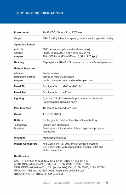
Power Input 10-32 VDC; 6W nominal, 25W max
Output ARINC 429 (high or low speed, see manual for specific labels)
Operating Range
Attitude 300° per second pitch, roll and yaw (max)Altitude -1,500 to +55,000 ft (-457 m to 16,764 m)Airspeed 20 to 500 knots (23 to 575 mph) (37 to 926 kph)
Heading Displayed via ARINC 429 input (external interface dependant)
Units of Measure
Altitude Feet or metersBarometric Setting Inches of mercury, millibars Airspeed Knots, miles per hour or kilometers per hour
Panel Tilt Configurable -90° to +90° pitch
Panel Roll Configurable ±5° roll
Lighting 5, 14 and 28 VDC external input or internal photocell Programmable dimming curve
Pilot Interface 16-detent, push and turn knob
Weight 1.6 lbs (0.73 kg)
Battery Rechargeable, field-replaceable, internal battery
Technology Lithium iron phosphateRun time 60 minutes minimum when fully charged and properly maintained
Mounting Front panel mounted
Mating Connectors Mid-Continent P/N 9017646 kit contains custom DB15 connector with configuration module, pitot and static connectors
Certification
FAA TSO certified to C2d, C3e, C4c, C10b, C106, C113a, C179aANAC TSO certified to C2d, C3e, C4c, C10b, C106, C113a, C179aEASA ETSO certified to C2d, C3d (incomplete), C4c, C10b, C106, C113, C179aRTCA DO-178B and DO-254 Design Assurance Level (DAL) ARTCA DO-160 and RTCA DO-311 qualified
PRODUCT SPECIFICATIONS
REV. G January 6, 2017 Manual Number 9017846 39