PILOT TRAINING GUIDE AURAL/VISUAL WARNING · List of Figures Graphic Title Figure For Training...
26
Table of Contents For Training Purposes Only May 03 3-i AURAL/VISUAL WARNING PILOT TRAINING GUIDE Introduction ......................................................................................................................... 3-1 Engine Indicating and Crew Alerting System (EICAS) ........................................................ 3-3 Description .................................................................................................................... 3-3 Components and Operation .......................................................................................... 3-3 EICAS Control Panel ............................................................................................... 3-3 EICAS Displays ....................................................................................................... 3-3 Data Concentrator Unit (DCU) ................................................................................ 3-4 Controls and Indicators ....................................................................................................... 3-6 Master Warning Switch/Lights....................................................................................... 3-6 Master Caution Switch/Lights........................................................................................ 3-6 Aural Warning Testing................................................................................................... 3-7 Aural Alert Disable ........................................................................................................ 3-8 EICAS Control Panel..................................................................................................... 3-8 PRI .......................................................................................................................... 3-8 STAT ....................................................................................................................... 3-8 STEP ....................................................................................................................... 3-9 HYD......................................................................................................................... 3-9 ELEC ....................................................................................................................... 3-9 CAS ......................................................................................................................... 3-9 F/CTL ...................................................................................................................... 3-9 EICAS Primary Page................................................................................................... 3-10 Engine Indications ................................................................................................. 3-10 Fuel Quantity ......................................................................................................... 3-10 Crew Alerting System Messages .......................................................................... 3-10 Cabin Pressurization ............................................................................................. 3-10 Landing Gear and Flaps........................................................................................ 3-10 Landing Gear Horn................................................................................................ 3-11 Trim Settings ......................................................................................................... 3-11 EICAS Status Page ..................................................................................................... 3-13 Crew Alerting System Messages .......................................................................... 3-13 Flight Spoilers ....................................................................................................... 3-13 Auxiliary Power Unit .............................................................................................. 3-13 Cabin Temperature ............................................................................................... 3-13 Bleed Air Pressure ................................................................................................ 3-13 Fuel Temperature.................................................................................................. 3-13 Oxygen Pressure .................................................................................................. 3-13 Cabin Pressurization ............................................................................................. 3-13 Synoptic Pages ..................................................................................................... 3-14 EICAS Messages ........................................................................................................ 3-14 Warning Messages ............................................................................................... 3-14 Caution Messages ................................................................................................ 3-15 Advisory Messages ............................................................................................... 3-15
Transcript of PILOT TRAINING GUIDE AURAL/VISUAL WARNING · List of Figures Graphic Title Figure For Training...

Table of Contents
For Training Purposes OnlyMay 03
3-i
AURAL/VISUAL WARNINGP I L O T T R A I N I N G G U I D E
Introduction .........................................................................................................................3-1
Engine Indicating and Crew Alerting System (EICAS)........................................................3-3Description ....................................................................................................................3-3Components and Operation ..........................................................................................3-3
EICAS Control Panel...............................................................................................3-3EICAS Displays.......................................................................................................3-3Data Concentrator Unit (DCU) ................................................................................3-4
Controls and Indicators .......................................................................................................3-6Master Warning Switch/Lights.......................................................................................3-6Master Caution Switch/Lights........................................................................................3-6Aural Warning Testing...................................................................................................3-7Aural Alert Disable ........................................................................................................3-8EICAS Control Panel.....................................................................................................3-8
PRI ..........................................................................................................................3-8STAT .......................................................................................................................3-8STEP.......................................................................................................................3-9HYD.........................................................................................................................3-9ELEC.......................................................................................................................3-9CAS.........................................................................................................................3-9F/CTL ......................................................................................................................3-9
EICAS Primary Page...................................................................................................3-10Engine Indications.................................................................................................3-10Fuel Quantity.........................................................................................................3-10Crew Alerting System Messages ..........................................................................3-10Cabin Pressurization .............................................................................................3-10Landing Gear and Flaps........................................................................................3-10Landing Gear Horn................................................................................................3-11Trim Settings .........................................................................................................3-11
EICAS Status Page.....................................................................................................3-13Crew Alerting System Messages ..........................................................................3-13Flight Spoilers .......................................................................................................3-13Auxiliary Power Unit ..............................................................................................3-13Cabin Temperature ...............................................................................................3-13Bleed Air Pressure ................................................................................................3-13Fuel Temperature..................................................................................................3-13Oxygen Pressure ..................................................................................................3-13Cabin Pressurization .............................................................................................3-13Synoptic Pages .....................................................................................................3-14
EICAS Messages ........................................................................................................3-14Warning Messages ...............................................................................................3-14Caution Messages ................................................................................................3-15Advisory Messages ...............................................................................................3-15

AURAL/VISUAL WARNING
3-ii For Training Purposes OnlyJan 04
P I L O T T R A I N I N G G U I D E
Status Messages................................................................................................... 3-16Takeoff Configuration Warning ................................................................................... 3-16Inhibited EICAS Caution Messages............................................................................ 3-16Display Reversionary Control ..................................................................................... 3-18
EICAS Reversionary Mode ................................................................................... 3-18Display Reversionary Control Panel ..................................................................... 3-18PFD Reversionary Mode....................................................................................... 3-18MFD Reversionary Mode ...................................................................................... 3-18
Maintenance Diagnostic Computer............................................................................. 3-20Description ............................................................................................................ 3-20Operation .............................................................................................................. 3-20
Flight Data Recorder................................................................................................... 3-21Description ............................................................................................................ 3-21Components and Operation .................................................................................. 3-21FDR EVENT Switch .............................................................................................. 3-21
EICAS Messages........................................................................................................ 3-22

List of FiguresGraphic Title Figure
For Training Purposes OnlyMay 03
3-iii
AURAL/VISUAL WARNINGP I L O T T R A I N I N G G U I D E
EICAS Displays Location ....................................................................................................3-1EICAS Control Panel (ECP)................................................................................................3-2Master Warning and Caution Lights....................................................................................3-3AURAL WARN / LAMP TEST Panel ...................................................................................3-4DCU Disable Controls.........................................................................................................3-5EICAS Control Panel ..........................................................................................................3-6EICAS Primary Page ..........................................................................................................3-7EICAS Status Page Displays ..............................................................................................3-8Display Reversionary Control Panel ...................................................................................3-9Maintenance Diagnostic Computer Switch .......................................................................3-10FDR EVENT Switch ..........................................................................................................3-11

3-iv For Training Purposes OnlyMay 03
AURAL/VISUAL WARNING P I L O T T R A I N I N G G U I D E
Page Intentionally Left Blank

AURAL/VISUAL WARNING
For Training Purposes OnlyMay 03
3-1
P I L O T T R A I N I N G G U I D E
CHAPTER 3: AURAL/VISUAL WARNING
IntroductionThe aural and visual warning system components provide the flight crew with aural, visual and tactile indications of potentially unsafe conditions as well as information about airplane configurations and engine data. The system also warns of airplane system malfunctions and non-normal situations.

AURAL/VISUAL WARNING
3-2 For Training Purposes OnlySept 04
P I L O T T R A I N I N G G U I D E
EICAS Displays Location Figure 3-1
EICAS Control Panel (ECP) Figure 3-2
BRTBRT
EICAS DISPLAY 1 (ED 1) EICAS DISPLAY 2 (ED 2)
AILERON MON OKPARKING BRAKE ONFLAPS MOTOR OVHT
CABIN TEMP
BLEED PRESS
FUEL TEMP
ENGINE
BULK
OXY
C ALT
RATE
P
502048
70 75
-20
2000
3200
200
-0.5SPOILERS
APU
95 430
RPM EGT
P6
04
_0
3_
00
1
BRTBRT
85.0 85.0
HOT
925 750
N190.0
ITT
N2
GEAR DISAGREEAUTO PRESS
DN DN DN
- GEAR - - FLAPS -
C ALT
STAB
RATE
- TRIM -
P
3200 200 -0.5
20
NU
ND
4.0
RUDDER
AIL
RWDLWD
NRNL
FF
OIL PRESS
OIL TEMP
FAN VIB
7160 4870
200004.2
115
82
3500
3140
- FUEL QTY - TOTAL
3500
82
165
1.2
4870
75.0 95.0
VIB
REV APR
PRI STAT STEP CKLST RCL EMER
HYD ELEC LMFD
RMFD
SEL/AUTO
CAS F/CTL SKP/3D
UP/PLAN
DN/SIDE
M
P6
04
_0
3_
00
2
AURAL/VISUAL WARNING
For Training Purposes OnlyMay 03
3-3
P I L O T T R A I N I N G G U I D E
Engine Indicating and Crew Alerting System (EICAS)
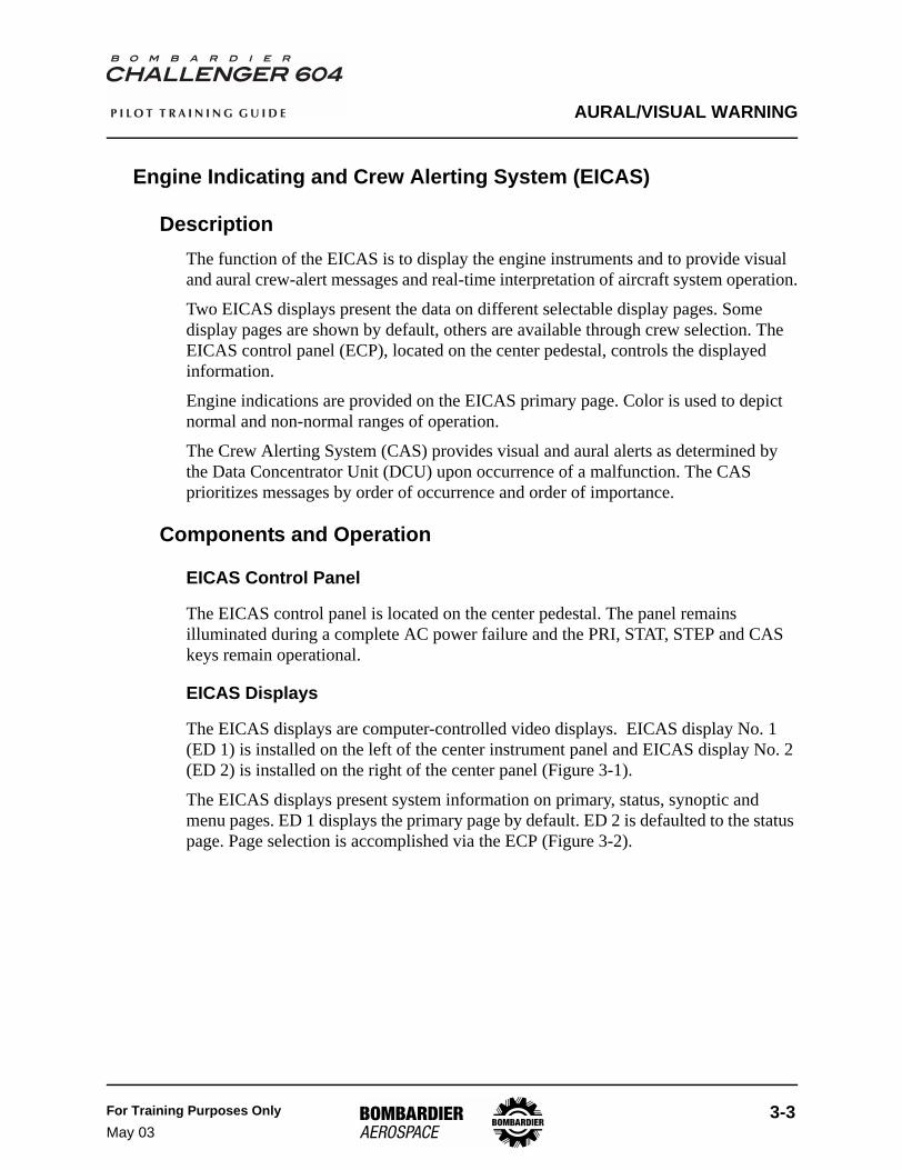
DescriptionThe function of the EICAS is to display the engine instruments and to provide visual and aural crew-alert messages and real-time interpretation of aircraft system operation.
Two EICAS displays present the data on different selectable display pages. Some display pages are shown by default, others are available through crew selection. The EICAS control panel (ECP), located on the center pedestal, controls the displayed information.
Engine indications are provided on the EICAS primary page. Color is used to depict normal and non-normal ranges of operation.
The Crew Alerting System (CAS) provides visual and aural alerts as determined by the Data Concentrator Unit (DCU) upon occurrence of a malfunction. The CAS prioritizes messages by order of occurrence and order of importance.
Components and Operation
EICAS Control Panel
The EICAS control panel is located on the center pedestal. The panel remains illuminated during a complete AC power failure and the PRI, STAT, STEP and CAS keys remain operational.
EICAS Displays
The EICAS displays are computer-controlled video displays. EICAS display No. 1 (ED 1) is installed on the left of the center instrument panel and EICAS display No. 2 (ED 2) is installed on the right of the center panel (Figure 3-1).
The EICAS displays present system information on primary, status, synoptic and menu pages. ED 1 displays the primary page by default. ED 2 is defaulted to the status page. Page selection is accomplished via the ECP (Figure 3-2).

AURAL/VISUAL WARNING
3-4 For Training Purposes OnlyMay 03
P I L O T T R A I N I N G G U I D E
Data Concentrator Unit (DCU)
The data concentrator unit is the heart of the EICAS. The DCU collects data from various aircraft systems, processes the information and relays it to the proper component or display. In a standard configuration, there are two DCUs installed in the aircraft. They are designated DCU 1 and DCU 2. An optional third DCU can be installed and is labeled DCU 3 as per service bulletin 604-31-001.
All DCUs share in providing information to the EICAS displays. Internal switching logic determines how the information is provided by the two or three DCUs. If a partial or complete failure of a DCU occurs, system redundancy ensures that no displayed data is lost. In aircraft with the optional third DCU, an additional level of redundancy is provided.
Data concentrator units receive inputs from the following systems:
• Engines• Landing gear• Flaps• Spoilers• Auxiliary Power Unit (APU)• Flight controls• Avionics• Stall Protection System• Ground Proximity Warning System (GPWS)• Traffic Alert and Collision Avoidance System (TCAS)• Crew Alerting System (CAS)• Air Data Computer (ADC) altitude alerting
The DCUs process and format this information then transmit the data on the ARINC bus to the following:
• EICAS displays• Lamp Driver Unit (LDU)• Audio Electronic Control Unit (AECU)• Flight Data Recorder (FDR)• Maintenance Diagnostic Computer (MDC)
The two-channel lamp driver unit receives information from the DCUs and controls the associated panel and glareshield switch/light illumination.
When a DCU generates an EICAS message, the data is sent to the LDU. The LDU then interprets the information and illuminates the switch/light on the appropriate control panel.

AURAL/VISUAL WARNING
For Training Purposes OnlyMay 03
3-5
P I L O T T R A I N I N G G U I D E
Should one channel of the LDU fail, the remaining channel continues to operate. Testing the LDU and panel lamps is accomplished by using the test switch located on the miscellaneous test panel. The three-position LAMP TEST switch is spring-loaded to the center OFF position. Holding the switch to position 1 or 2 tests the associated LDU channel and lamps.
AC power is required to perform the lamp test.
NOTE

AURAL/VISUAL WARNING
3-6 For Training Purposes OnlyMay 03
P I L O T T R A I N I N G G U I D E
Controls and Indicators
Master Warning Switch/LightsThe master warning switch/lights are located on the glareshield. When the DCUs generate a warning message, the two master warning switch/lights flash red. A triple attenson always accompanies the master warning lights and, in addition, dedicated tones or voice messages may sound.
When the switch/light is pressed, the flashing red light and the audio alerts are reset.
Master Caution Switch/LightsThe master caution switch/lights are located on the glareshield. When the DCUs generate a caution message, the two master caution switch/lights flash amber. A single attenson always accompanies the master caution lights.
When the switch/light is pressed, the flashing amber light is reset.
Master Warning and Caution Lights Figure 3-3
LH ENGFIREPUSH
GPWSTERRINHB
MASTERWARNING BOTTLE 1
ARMEDPUSH TO
DISCH
STALLMASTERCAUTION
PULL UP
GND PROX
ATS
N2 SYNC
ATS
N1 TO
FAIL
ATS
N1 TO
FAIL
APUFIREPUSH
RH ENGFIREPUSH
GPWSTERRINHB
MASTERWARNINGBOTTLE 2
ARMEDPUSH TO
DISCH
BOTTLEARMED
PUSH TODISCH
STALLMASTERCAUTION
PULL UP
GND PROX
RIGHT GLARESHIELD
P6
04
_0
3_
00
3
LEFT GLARESHIELD
AURAL/VISUAL WARNING
For Training Purposes OnlyMay 03
3-7
P I L O T T R A I N I N G G U I D E
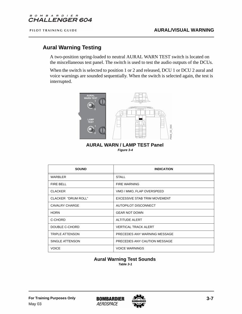
Aural Warning TestingA two-position spring-loaded to neutral AURAL WARN TEST switch is located on the miscellaneous test panel. The switch is used to test the audio outputs of the DCUs.
When the switch is selected to position 1 or 2 and released, DCU 1 or DCU 2 aural and voice warnings are sounded sequentially. When the switch is selected again, the test is interrupted.
AURAL WARN / LAMP TEST Panel Figure 3-4
Aural Warning Test Sounds Table 3-1
SOUND INDICATION
WARBLER STALL
FIRE BELL FIRE WARNING
CLACKER VMO / MMO, FLAP OVERSPEED
CLACKER “DRUM ROLL” EXCESSIVE STAB TRIM MOVEMENT
CAVALRY CHARGE AUTOPILOT DISCONNECT
HORN GEAR NOT DOWN
C-CHORD ALTITUDE ALERT
DOUBLE C-CHORD VERTICAL TRACK ALERT
TRIPLE ATTENSON PRECEDES ANY WARNING MESSAGE
SINGLE ATTENSON PRECEDES ANY CAUTION MESSAGE
VOICE VOICE WARNINGS
P6
04
_0
3_
00
4
AURALWARN TEST
LAMPTEST
1
2
1
2

AURAL/VISUAL WARNING
3-8 For Training Purposes OnlyMay 03
P I L O T T R A I N I N G G U I D E
Aural Alert DisableTwo (third optional) DISABLE switch/lights, located on the AUDIO WARNING panel on the copilot side console, are used to disable and silence the aural warnings of a malfunctioning DCU. When DCU 1 is selected to DISABLE, DCU 2 will provide the aural warning function. When both DCU 1 and 2 are disabled, the optional DCU 3 (if installed) provides the aural warnings. The ground proximity warning system (GPWS) and the traffic alert and collision avoidance system (TCAS) aural warnings are not disabled by selections at the audio warning panel.
DCU Disable Controls Figure 3-5
In order to test DCU 3 audio warnings, DCU 1 or 2 must be disabled from the audio warning disable panel.
EICAS Control Panel
PRI
Selecting PRI causes the primary page to be displayed on ED 1.
STAT
Pressing the STAT button causes the status page to be displayed on ED 2. If the status page is already displayed, the button will remove the status message(s) and display a white MSGS icon. Pressing the STAT a second time will cause the status message(s) to reappear. DCU generation of a new status message will remove the MSGS icon and the new status message will be displayed on the top of the status message stack.
NOTE
DCU 1 DCU 2 DCU 3
AUDIO WARNING
DISABLEDISABLEDISABLE
P6
04
_0
3_
00
5
AURAL/VISUAL WARNING
For Training Purposes OnlyMay 03
3-9
P I L O T T R A I N I N G G U I D E
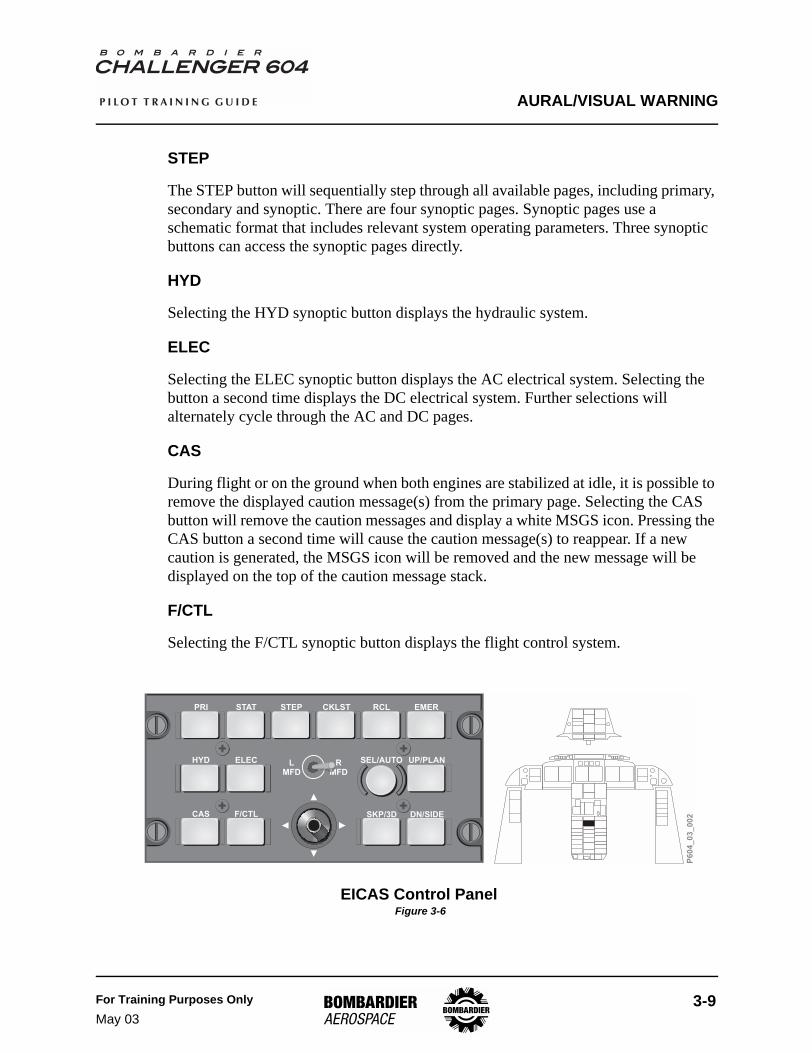
STEP
The STEP button will sequentially step through all available pages, including primary, secondary and synoptic. There are four synoptic pages. Synoptic pages use a schematic format that includes relevant system operating parameters. Three synoptic buttons can access the synoptic pages directly.
HYD
Selecting the HYD synoptic button displays the hydraulic system.
ELEC
Selecting the ELEC synoptic button displays the AC electrical system. Selecting the button a second time displays the DC electrical system. Further selections will alternately cycle through the AC and DC pages.
CAS
During flight or on the ground when both engines are stabilized at idle, it is possible to remove the displayed caution message(s) from the primary page. Selecting the CAS button will remove the caution messages and display a white MSGS icon. Pressing the CAS button a second time will cause the caution message(s) to reappear. If a new caution is generated, the MSGS icon will be removed and the new message will be displayed on the top of the caution message stack.
F/CTL
Selecting the F/CTL synoptic button displays the flight control system.
EICAS Control Panel Figure 3-6
PRI STAT STEP CKLST RCL EMER
HYD ELEC LMFD
RMFD
SEL/AUTO
CAS F/CTL SKP/3D
UP/PLAN
DN/SIDE
M
P6
04
_0
3_
00
2

AURAL/VISUAL WARNING
3-10 For Training Purposes OnlyMay 03
P I L O T T R A I N I N G G U I D E
EICAS Primary PageED 1’s default display is the EICAS primary page.
Engine Indications
Engine indications are presented in both traditional analog gauge format and digital readouts. Displayed engine parameters include:
• N1 speed gauge• N1 Takeoff thrust setting• Inter-Turbine Temperature (ITT) gauge• N2 speed gauge• fuel flow• oil pressure• oil temperature• fan vibration
Fuel Quantity
In the bottom left-hand corner of the primary page, EICAS provides the pilot with a summary of current fuel quantities. This includes the individual main tank quantities, the auxiliary tank system total quantity, the tail tank system total quantity and the aircraft’s total fuel quantity readout.
Crew Alerting System Messages
Warning and Caution messages are presented only on the EICAS primary page.
Cabin Pressurization
Cabin pressurization data is displayed on the primary page when the pressurization control (PRESS CONT) switch is selected to MANUAL on the Cabin Pressurization control panel. This function is further explained in the Air Conditioning/Pressurization chapter.
Landing Gear and Flaps
Landing gear and flap position information is presented on the EICAS primary page. During flight, the landing gear and flap information is removed from view after 30 seconds when both of the following conditions exist:
• landing gear is up and locked• flaps are up

AURAL/VISUAL WARNING
For Training Purposes OnlyMay 03
3-11
P I L O T T R A I N I N G G U I D E
Landing Gear Horn
A landing gear horn will sound if certain parameters are not met with respect to combinations of altitude, speed, flap and power lever positions. (See Chapter 15 Landing Gear and Brakes)
Trim Settings
Aileron, horizontal stabilizer and rudder trim settings are continuously displayed on the primary page.
EICAS Primary Page Figure 3-7
BRTBRT
85.0 85.0
95.0
HOT
750 750
N190.0
ITT
N2
GEAR DISAGREEAUTO PRESS
DN DN DN
- GEAR - - FLAPS -
C ALT
STAB
RATE
- TRIM -
P
3100 2000 3.0
20
NU
ND
4.0
RUDDER
AIL
RWDLWD
NRNL
FF
OIL PRESS
OIL TEMP
FAN VIB
7160 4870
20000
1.2
115
82
3500
3140
- FUEL QTY - TOTAL
3500
82
115
1.2
4870
PressurizationIndications(in MANUALmode only)
FuelQuantityIndications
GEAR and FLAPIndications
EngineIndications
P6
04
_0
3_
00
6CAS Messages
75.0
VIB
REV APR
TrimDisplay

AURAL/VISUAL WARNING
3-12 For Training Purposes OnlyMay 03
P I L O T T R A I N I N G G U I D E
EICAS Status Page Displays Figure 3-8
113405
V
HZEXTAC
AC ELECTRICAL
UTIL BUS 1
GEN2
SHEDSHED
AUTOXFEROFF
GEN1
AUTOXFERFAIL
APU
BUS 1
UTIL BUS 2
000
KVAVHZ
GEN
00
V
HZADG
ESS BUS
15115400
KVAVHZ
000
KVAVHZ
BUS 2
AC ELECTRICAL
BRTBRT
Advisory EICASMessages
OxygenPressure
CabinAltitude
Cabin Rate
Cabin Diff.SpoilerDeploymentIndication
L and R 10th-Stage BleedAir Pressure
FuelTemperature
Flight SpoilerIndicatorIndicatesrelative spoilerposition
Ground SpoilerIndicator
CabinTemperature
WING A/ICE OKT/O CONFIG OKL FUEL PUMP ONR FUEL PUMP ONHYD SOV1 CLSDHYD SOV2 CLSDPARKING BRAKE ONAC UTIL 1 OFFFUEL CH 1 FAILYD 1 INOP
CABIN TEMP
BLEED PRESS
FUEL TEMP
ENGINE
BULK
OXY
C ALT
RATE
P
502050
40 30
-20
1850
200
0
-0.5SPOILERS
APU
95 430
RPM EGT
P6
04
_0
3_
00
7
FLIGHT CONTROLS
FLAPS 30
FLAPS MOTOR OVERHEAT
AIL AIL
RUDDER
YAW DAMPERSTAB TRIM CH1 INOP
ELEV ELEV
FLIGHT CONTROLS
DC ELECTRICAL
TRU 1
V
A
2818
TRU 2
V
A
2818
2711
V
A
V
A
2711
240
V
A
240
V
A
ESSTRU 2
APUBATT
MAINBATT
ESSTRU 1
BUS 1
BUS 2
UTIL BUS 1
UTIL BUS 2
EMER BUS
APU BATTDIR BUS
MAIN BATTDIR BUS
AC BUS 1 AC BUS 2AC ESS
BUS
CHGR OFF
TIE
ESS BUS
BATT BUS
DC ELECTRICAL
1B 3A 3B 2B
3050PSI
3000PSI
2950PSI
INBDBRAKES
PSI3000
OUTBDBRAKES
PSI3000
80 °C 15 °C
RUDDERL ELEVATORL AILERONFLT SPLRGND SPLR
RUDDERL ELEVATOR RL AILERON RLNDG GEARN/W STEERNOSE DOOR
RUDDERELEVATOR RAILERON RFLT SPLR
MLG AUX ACT
1A 2A
49%
HYDRAULIC
95 °C
82% 76%
HYDRAULIC
Status EICASMessages
APU RPM andEGT Indicators

AURAL/VISUAL WARNING
For Training Purposes OnlyMay 03
3-13
P I L O T T R A I N I N G G U I D E
EICAS Status PageThe status page is the default display of ED 2.
Crew Alerting System Messages
Advisory and status messages are presented only on the EICAS status page.
Flight Spoilers
When deployed, the flight spoilers’ extension will be presented at the bottom left-hand corner of the EICAS status page. When retracted, the display disappears.
Auxiliary Power Unit
The APU RPM and EGT gauges are displayed on the EICAS status page when the APU PWR FUEL switch is selected.
Cabin Temperature
The cabin temperature is displayed in degrees Celsius.
Bleed Air Pressure
The bleed air pressure of the left and right 10th-stage manifold is indicated in pounds per square inch (psi).
Fuel Temperature
The fuel temperatures at the engines and in the left main tank (bulk) is provided in degrees Celsius.
Oxygen Pressure
The gaseous oxygen pressure is continuously displayed on the status page. Green indicates normal pressure and amber identifies pressure below 800 psi.
Cabin Pressurization
Cabin pressurization is displayed on the status page. The information includes:
• cabin altitude in feet• rate of climb or descent in feet/minute• differential pressure in psi
AURAL/VISUAL WARNING
3-14 For Training Purposes OnlyMay 03
P I L O T T R A I N I N G G U I D E
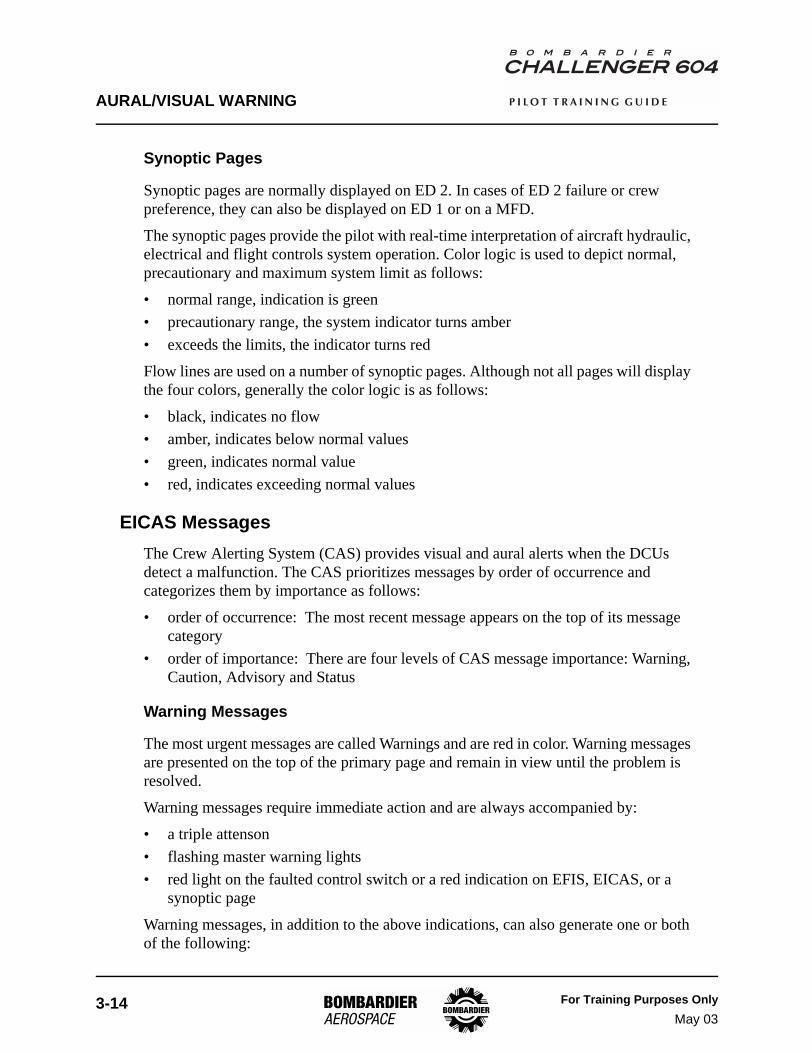
Synoptic Pages
Synoptic pages are normally displayed on ED 2. In cases of ED 2 failure or crew preference, they can also be displayed on ED 1 or on a MFD.
The synoptic pages provide the pilot with real-time interpretation of aircraft hydraulic, electrical and flight controls system operation. Color logic is used to depict normal, precautionary and maximum system limit as follows:
• normal range, indication is green• precautionary range, the system indicator turns amber• exceeds the limits, the indicator turns red
Flow lines are used on a number of synoptic pages. Although not all pages will display the four colors, generally the color logic is as follows:
• black, indicates no flow• amber, indicates below normal values• green, indicates normal value• red, indicates exceeding normal values
EICAS MessagesThe Crew Alerting System (CAS) provides visual and aural alerts when the DCUs detect a malfunction. The CAS prioritizes messages by order of occurrence and categorizes them by importance as follows:
• order of occurrence: The most recent message appears on the top of its message category
• order of importance: There are four levels of CAS message importance: Warning, Caution, Advisory and Status
Warning Messages
The most urgent messages are called Warnings and are red in color. Warning messages are presented on the top of the primary page and remain in view until the problem is resolved.
Warning messages require immediate action and are always accompanied by:
• a triple attenson• flashing master warning lights• red light on the faulted control switch or a red indication on EFIS, EICAS, or a
synoptic page
Warning messages, in addition to the above indications, can also generate one or both of the following:

AURAL/VISUAL WARNING
For Training Purposes OnlyMay 03
3-15
P I L O T T R A I N I N G G U I D E
• aural warning tone• voice message
Pressing either master warning switch/light:
• silences the aural alerts• stops the master warning lights from flashing• resets the switch/light to allow it to indicate another fault
Caution Messages
Caution messages are second in order of importance. Caution messages are presented in amber on the primary page and appear directly below any warning messages that may be displayed. It is possible to have more than one page of caution messages. The CAS pushbutton on the ECP allows the pilot to page forward and backward to view the entire list of caution messages. During flight or on the ground when both engines are stabilized at idle, caution message(s) can be removed from view or recalled to the screen by pressing the CAS key on the ECP. A white MSGS icon will appear, advising the crew that the caution message(s) are out of view. Pressing the CAS button a second time will cause the caution message(s) to reappear. DCU generation of a new caution message will remove the MSGS icon and the new message will be displayed on the top of the caution message stack.
Caution messages require prompt action and are always accompanied by:
• a single attenson• flashing master caution lights• amber light on the faulted control switch or an amber indication on EFIS, EICAS,
or a synoptic page
Pressing either master caution switch/light:
• stops the flashing of the master caution lights• resets the master caution switch/light to allow it to annunciate another fault
Advisory Messages
Green advisory messages are presented at the top of the status page. Advisory messages cannot be removed from view until the cause is deselected or deactivated. Advisory messages are used to advise of:
• aircraft configuration for a particular phase of flight• successful system test• confirmation of SOV closure• SELCAL

AURAL/VISUAL WARNING
3-16 For Training Purposes OnlyJan 04
P I L O T T R A I N I N G G U I D E
Status Messages
White status messages are presented on the status page and appear directly below any advisory messages that may be present. Status message(s) can be removed from view or recalled to the screen by pressing the STAT key on the ECP. A white MSGS icon will appear, advising the crew that the status message(s) are out of view. Pressing the STAT button a second time will allow the status message(s) to reappear. DCU generation of a new status message will remove the MSGS icon and the new message will be displayed on the top of the status message stack. Status messages are used to inform of:
• status of a specific system that has been manually or automatically activated/deactivated
• low-priority system failures
Takeoff Configuration WarningThe Takeoff Configuration Warnings are armed on the ground when both engines accelerate as a result of thrust levers being advanced above 70% N1. A voice warning, an EICAS warning message and flashing red Master Warning annunciators are provided for any of the following conditions:
All TOC warnings are canceled when the configuration error is corrected.
Inhibited EICAS Caution MessagesDuring takeoff and landing, the DCU logic inhibits distracting EICAS caution messages. The logic inhibits messages during takeoff when the left and right engine N1 are greater or equal to 79% and above 80 kts with weight-on-wheels. On landing, the messages are inhibited when radio altitude is less than 400 feet above ground level (AGL) with landing gear extended.
CONDITION VOICE WARNING EICAS MESSAGE MASTER WARNING
AUTOPILOT ENGAGED “CONFIG AUTOPILOT” CONFIG AP FLASHES
FLAPS NOT SET FOR TAKEOFF “CONFIG FLAPS” CONFIG FLAPS FLASHES
ALL SPOILERS NOT IN TAKEOFF POSITION “CONFIG SPOILERS” CONFIG SPOILERS FLASHES
HORIZONTAL STAB NOT IN T/O RANGE “CONFIG TRIM” CONFIG STAB FLASHES
PARKING BRAKE SET “CONFIG BRAKES” PARKING BRAKE FLASHES
Takeoff Configuration Warnings Table 3-2

AURAL/VISUAL WARNING
For Training Purposes OnlyJan 04
3-17
P I L O T T R A I N I N G G U I D E
The inhibit logic is removed when:
• left and right engine N1 are less than 67.6%; or• radio altitude is greater than 400 feet AGL with the landing gear extended; or• 30 seconds after the inhibit starts; or• 30 seconds after the air-to-ground transition
Caution messages and their associated aural alerts that are NOT inhibited during takeoff and landings are shown in the following table.
AIRPLANE SYSTEM CAUTION MESSAGE NOT INHIBITED TAKEOFF LANDING
POWER PLANT
APR INOP √ √
APR CMD SET √
L (R) REV UNLOCKED √ √
L (R) REV UNSAFE √ √
AUTOMATIC FLIGHT CONTROL SYSTEM
AP TRIM IS LWD (RWD) (ND) (NU) √
AP PITCH TRIM √
YAW DAMPER √
FIRE PROTECTIONAPU BTL LO √
ENG BTL 1 (2) LO √
FLIGHT CONTROLS
ELEVATOR SPLIT √ √
FLAPS FAIL √
FLT SPLRS √
FLT SPLRS DEPLOY √
GND SPLRS √
GND SPLRS DEPLOY √ √
GND SPLRS NOT ARMED √
STAB TRIM √
FUELFUEL IMBALANCE √
L (R) FUEL LO PRESS √ √
HYDRAULICS HYD 3 LO PRESS √
INSTRUMENTS EFIS COMP MON √ √
LANDING GEAR
A/SKID INBD (OUTBD) √ √
INBD (OUTBD) BRAKE PRESS √ √
PROX SYS √
STEERING INOP √
WOW INPUT OR OUTPUT √
Caution Messages Not Inhibited during Takeoff and Landing Table 3-3

AURAL/VISUAL WARNING
3-18 For Training Purposes OnlyMay 03
P I L O T T R A I N I N G G U I D E
Display Reversionary Control
EICAS Reversionary Mode
The EICAS reversionary mode provides an alternate method of displaying EICAS information should ED 1 or ED 2 fail.
In the event of ED 1 failure, the primary page is automatically transferred to ED 2. This automatic feature ensures that engine indications and warning and caution messages are always available to the pilot. There is no automatic transfer of status page information should ED 2 fail.
Display Reversionary Control Panel
The display reversionary control panel is located on the center pedestal. The reversionary selector switches (L MFD, EICAS, R MFD) are used when a malfunction exists.
The L MFD and R MFD reversionary switches are identical, and have three positions designated as PFD, NORM and EICAS. In EICAS position, the status-page information is displayed by default on the MFD.
The EICAS reversionary selector is also a three-position switch designated as NORM, ED 1 and ED 2. In the NORM position, normal EICAS display is represented on ED 1 and ED 2. When the selector is moved to either ED 1 or ED 2 position, the opposite ED is disabled and blanked while the primary and secondary information is available on the selected display.
PFD Reversionary Mode
When a primary flight display (PFD) fails, the information can be transferred to the associated MFD. The L (R) MFD rotary knob on the display reversionary control panel, when selected to the PFD position, effects the transfer.
MFD Reversionary Mode
There is no reversionary mode for the data normally presented on the multifunction displays (MFDs).

AURAL/VISUAL WARNING
For Training Purposes OnlyMay 03
3-19
P I L O T T R A I N I N G G U I D E
Display Reversionary Control Panel Figure 3-9
P6
04
_0
3_
00
9
VFE (45 FLAPS)VFE (30 FLAPS)VFE (20 FLAPS)VA (MANEUVERING)(AT SEA LEVEL 48,200LB)(AT 20,000FT 26,000LB)VNO (BELOW 8,000FT)VNO (8,000 TO 22,150 FT)
AIRSPEED LIMITS - (INDICATED SPEEDS)
MMO (22,150FT TO 26,570FT)VMO (26,570FT TO 30,990FT)MMO (30,990FT TO 41,000FT)VLO (EXT) (L/G EXTENSION)VLO (RET) (L/G RETRACTION)VLE (L/G EXTENDED)
189197231
248187300348
0.783180.85197197250
P
UL L
P
UL L
TO
C A G
E
C A G
E
CLI MB
DI VE
OFF
BRT
BRT
BRT
0.0
0.0
0.0
0.0
180 180
N1
ITT
N2
STAB- TRIM -
NU
ND
5.0
RUDDER
AIL
RWDLWD
NRNL
FF (PPH)
OIL PRESS
OIL TEMP
FAN VIB
0 4050
81000.0
33
0
0
0
- FUEL (LBS) - TOTAL
0
0
33
0.0
4050
DN DN DN
- GEAR - - FLAPS - 20
R ENG OIL PRESSL ENG OIL PRESSL WSHLD HEATL WINDOW HEATINBD BRAKE PRESSR WSHLD HEATR WINDOW HEATOUTBD BRAKE PRESSR PROBE HEAT OFFL PROBE HEAT OFFHYD 3 LO PRESS
BRT
CABIN TEMP
BLEED PRESS
FUEL TEMP
ENGINE
BULK
OXY
C ALT
RATE
P
47
23
0
36 35
1820
100
0
0.0
APU
100 323
RPM EGT
R FUEL PUMP ONL FUEL PUMP ONDOOR CLOSEDPARKING BRAKE ONPROX SYS FAULTFDR FAIL
SPOILERS
15
2 000234
ALT
0
7 3
2
1
4
9
6 29925
1014
400
350
300 250
200
150
10060
KTS
IAS
FEET
X 1000
CABIN
ALTITUDE
0
4
2
68
10
20
30
45
BRT
BRT
80
60
20
00
20
10
10
20
300
200
100
100
000
80004
RA2IRS2ADC2DCP2
TERM
VOR1
TRU
NO FLIGHT PLAN
TCASOFF
29.92 IN
2400M
GSRA
TOLOC 1
DR TOALTS
FMS1
12DTK 333
.7YUL
NM
4
4
2
2
1
1
2500M200
N33 1
512
E6
3
0
3000
40
VT 150
V2 133
VR 121
V1 113
ADF2
0FT
2
1
VFE (45 FLAPS)VFE (30 FLAPS)VFE (20 FLAPS)VA (MANEUVERING)(AT SEA LEVEL 48,200LB)(AT 20,000FT 26,000LB)VNO (BELOW 8,000FT)VNO (8,000 TO 22,150 FT)
AIRSPEED LIMITS - (INDICATED SPEEDS)
MMO (22,150FT TO 26,570FT)VMO (26,570FT TO 30,990FT)MMO (30,990FT TO 41,000FT)VLO (EXT) (L/G EXTENSION)VLO (RET) (L/G RETRACTION)VLE (L/G EXTENDED)
189197231
248187300348
0.783180.85197197250
80
60
20
00
20
10
10
20
300
200
100
100
000
80004
RA2IRS2ADC2DCP2
VOR1
TRU
TCASOFF
29.92 IN
2400M
GSRA
TOLOC 1
DR TOALTS
4
4
2
2
1
1
2500M200
0
3000
40
VT 150
V2 133
VR 121
V1 113
ADF2
0FT
2
1
FMS2
12DTK 056
.2LONNA
NM
TERM
N33 1
512
E6
3
CABIN TEMP
BLEED PRESS
FUEL TEMP
ENGINE
BULK
OXY
C ALT
RATE
P
47
23
0
36 35
1820
100
0
0.0
APU
100 323
RPM EGT
R FUEL PUMP ONL FUEL PUMP ONDOOR CLOSEDPARKING BRAKE ONPROX SYS FAULTFDR FAIL
SPOILERS
15
PFD EICASNORM
L MFD
EICAS PFDNORM
R MFD
ED1
ED2
NORMEICAS
D EIC2
AS PF
PFD EICASNORM
L MFD
1 2
NORMADC
1 2
NORMDCP
EICAS PFDNORM
R MFD
ED1
ED2
NORMEICAS
2
D EIC2
AS PF
2
REVERSIONARY SELECTORS -DISPLAY REVERSIONARY CONTROL PANEL
Display ReversionarySelector must be selectedto display PFD on MFD
VFE (45 FLAPS)VFE (30 FLAPS)VFE (20 FLAPS)VA (MANEUVERING)(AT SEA LEVEL 48,200LB)(AT 20,000FT 26,000LB)VNO (BELOW 8,000FT)VNO (8,000 TO 22,150 FT)
AIRSPEED LIMITS - (INDICATED SPEEDS)
MMO (22,150FT TO 26,570FT)VMO (26,570FT TO 30,990FT)MMO (30,990FT TO 41,000FT)VLO (EXT) (L/G EXTENSION)VLO (RET) (L/G RETRACTION)VLE (L/G EXTENDED)
189197231
248187300348
0.783180.85197197250
P
UL L
P
UL L
TO
C A G
E
C A G
E
CLI MB
DI VE
OFF
BRT
BRT
BRT
0.0
0.0
0.0
0.0
180 180
N1
ITT
N2
STAB- TRIM -
NU
ND
5.0
RUDDER
AIL
RWDLWD
NRNL
FF (PPH)
OIL PRESS
OIL TEMP
FAN VIB
0 4050
81000.0
33
0
0
0
- FUEL (LBS) - TOTAL
0
0
33
0.0
4050
DN DN DN
- GEAR - - FLAPS - 20
R ENG OIL PRESSL ENG OIL PRESSL WSHLD HEATL WINDOW HEATINBD BRAKE PRESSR WSHLD HEATR WINDOW HEATOUTBD BRAKE PRESSR PROBE HEAT OFFL PROBE HEAT OFFHYD 3 LO PRESS
BRT
CABIN TEMP
BLEED PRESS
FUEL TEMP
ENGINE
BULK
OXY
C ALT
RATE
P
47
23
0
36 35
1820
100
0
0.0
APU
100 323
RPM EGT
R FUEL PUMP ONL FUEL PUMP ONDOOR CLOSEDPARKING BRAKE ONPROX SYS FAULTFDR FAIL
SPOILERS
15
2 000234
ALT
0
7 3
2
1
4
9
6 29925
1014
400
350
300 250
200
150
10060
KTS
IAS
FEET
X 1000
CABIN
ALTITUDE
0
4
2
68
10
20
30
45
BRT
BRT
80
60
20
00
20
10
10
20
300
200
100
100
000
80004
RA2IRS2ADC2DCP2
TERM
VOR1
TRU
NO FLIGHT PLAN
TCASOFF
29.92 IN
2400M
GSRA
TOLOC 1
DR TOALTS
FMS1
12DTK 333
.7YUL
NM
4
4
2
2
1
1
2500M200
N33 1
512
E6
3
0
3000
40
VT 150
V2 133
VR 121
V1 113
ADF2
0FT
2
1
VFE (45 FLAPS)VFE (30 FLAPS)VFE (20 FLAPS)VA (MANEUVERING)(AT SEA LEVEL 48,200LB)(AT 20,000FT 26,000LB)VNO (BELOW 8,000FT)VNO (8,000 TO 22,150 FT)
AIRSPEED LIMITS - (INDICATED SPEEDS)
MMO (22,150FT TO 26,570FT)VMO (26,570FT TO 30,990FT)MMO (30,990FT TO 41,000FT)VLO (EXT) (L/G EXTENSION)VLO (RET) (L/G RETRACTION)VLE (L/G EXTENDED)
189197231
248187300348
0.783180.85197197250
80
60
20
00
20
10
10
20
300
200
100
100
000
80004
RA2IRS2ADC2DCP2
VOR1
TRU
TCASOFF
29.92 IN
2400M
GSRA
TOLOC 1
DR TOALTS
4
4
2
2
1
1
2500M200
0
3000
40
VT 150
V2 133
VR 121
V1 113
ADF2
0FT
2
1
FMS2
12DTK 056
.2LONNA
NM
TERM
N33 1
512
E6
3
VFE (45 FLAPS)VFE (30 FLAPS)VFE (20 FLAPS)VA (MANEUVERING)(AT SEA LEVEL 48,200LB)(AT 20,000FT 26,000LB)VNO (BELOW 8,000FT)VNO (8,000 TO 22,150 FT)
AIRSPEED LIMITS - (INDICATED SPEEDS)
MMO (22,150FT TO 26,570FT)VMO (26,570FT TO 30,990FT)MMO (30,990FT TO 41,000FT)VLO (EXT) (L/G EXTENSION)VLO (RET) (L/G RETRACTION)VLE (L/G EXTENDED)
189197231
248187300348
0.783180.85197197250
P
UL L
P
UL L
TO
C A G
E
C A G
E
CLI MB
DI VE
OFF
BRT
059
WX + TRBUTC TAS GS TAT11:01 0 0 15 C
VOR 1 ADF 2
VOR1YULTTG--:--
CRS 01212.7NM
SAT 15 C
FMS2LONNA
DTK05612.2 NMTTG --:--
33
30
21
S15
12
6
3
N
E
W
24
BRT
BRT
0.0
0.0
0.0
0.0
180 180
N1
ITT
N2
STAB- TRIM -
NU
ND
5.0
RUDDER
AIL
RWDLWD
NRNL
FF (PPH)
OIL PRESS
OIL TEMP
FAN VIB
0 4050
81000.0
33
0
0
0
- FUEL (LBS) - TOTAL
0
0
33
0.0
4050
DN DN DN
- GEAR - - FLAPS - 20
R ENG OIL PRESSL ENG OIL PRESSL WSHLD HEATL WINDOW HEATINBD BRAKE PRESSR WSHLD HEATR WINDOW HEATOUTBD BRAKE PRESSR PROBE HEAT OFFL PROBE HEAT OFFHYD 3 LO PRESS
BRT
CABIN TEMP
BLEED PRESS
FUEL TEMP
ENGINE
BULK
OXY
C ALT
RATE
P
47
23
0
36 35
1820
100
0
0.0
APU
100 323
RPM EGT
R FUEL PUMP ONL FUEL PUMP ONDOOR CLOSEDPARKING BRAKE ONPROX SYS FAULTFDR FAIL
SPOILERS
15
2 000234
ALT
0
7 3
2
1
4
9
6 29925
1014
400
350
300 250
200
150
10060
KTS
IAS
FEET
X 1000
CABIN
ALTITUDE
0
4
2
68
10
20
30
45
BRT
BRT
80
60
20
00
20
10
10
20
300
200
100
100
000
80004
RA2IRS2ADC2DCP2
TERM
VOR1
TRU
NO FLIGHT PLAN
TCASOFF
29.92 IN
2400M
GSRA
TOLOC 1
DR TOALTS
FMS1
12DTK 333
.7YUL
NM
4
4
2
2
1
1
2500M200
N33 1
512
E6
3
0
3000
40
VT 150
V2 133
VR 121
V1 113
ADF2
0FT
2
1
CYUL
TOC
ALEXS
3
059
N
E
12
25
WX+TRB
UTC TAS GS TAT11:01 0 0 SAT 15 C 15 C
VOR 1 FMS MAP ADF 2
CYULLONNAALEXSCYUL
1NM12NM20NM
111NM
0:030:040:23
11:0211:0511:0711:25 7137LB 35.6GM
12.5
DME 1
YUL12.7
DME 2–– – –
LONNA
VFE (45 FLAPS)VFE (30 FLAPS)VFE (20 FLAPS)VA (MANEUVERING)(AT SEA LEVEL 48,200LB)(AT 20,000FT 26,000LB)VNO (BELOW 8,000FT)VNO (8,000 TO 22,150 FT)
AIRSPEED LIMITS - (INDICATED SPEEDS)
MMO (22,150FT TO 26,570FT)VMO (26,570FT TO 30,990FT)MMO (30,990FT TO 41,000FT)VLO (EXT) (L/G EXTENSION)VLO (RET) (L/G RETRACTION)VLE (L/G EXTENDED)
189197231
248187300348
0.783180.85197197250
80
60
20
00
20
10
10
20
300
200
100
100
000
80004
RA2IRS2ADC2DCP2
VOR1
TRU
TCASOFF
29.92 IN
2400M
GSRA
TOLOC 1
DR TOALTS
4
4
2
2
1
1
2500M200
0
3000
40
VT 150
V2 133
VR 121
V1 113
ADF2
0FT
2
1
FMS2
12DTK 056
.2LONNA
NM
TERM
N33 1
512
E6
3
PFD EICASNORM
L MFD
EICAS PFDNORM
R MFD
ED1
ED2
NORMEICAS
D EIC2
AS PF
Display ReversionarySelector must be selectedto display EICAS on MFD

AURAL/VISUAL WARNING
3-20 For Training Purposes OnlyMay 03
P I L O T T R A I N I N G G U I D E
Maintenance Diagnostic Computer
Description
The maintenance diagnostic computer (MDC) is an onboard computer that is used to record aircraft mechanical and avionics system data. Maintenance personnel can retrieve the information for use in engine trend analysis, significant event recording and for avionics/aircraft system failure detection.
Operation
The MDC continuously records data for fault analysis and engine trend monitoring. The MDC data is downloadable to a maintenance facility computer.
MDC data is available on the flight deck by means of a red guarded switch on circuit breaker panel number one (CBP 1). Data can be displayed on MFD 1 or MFD 2, as determined by switch selection. Instructions on MDC data presentation are displayed on the selected MFD.
Maintenance Diagnostic Computer Switch Figure 3-10
P6
04
_0
3_
00
8
7.5
POWER MUST BE OFF BEFORE OPENING PANEL CBP-1
R
S
T
TEST
NORM
OFF
MAINT ADSHC
MFD 1
MFD 2
FIREEXT 2
R ENGR ENG
R ENG
FIREEXT 1
APUFIREEXT
PWRSENSE
FEED
L ENGL ENG
R ENGL ENG L ENG
28 VDC EMERGENCY BUS
28 VDC EMERGENCY BUS
APU
FUEL SOV HYD SOV
1
1
1
2
2
2
3
3
3
4
4
4
5
5
5
6
6
6
7
7
7
203 333
3
3
7.5 7.5 7.57.5
CIRCUIT BREAKER PANEL CBP - 1(LOWER)
MFD Guarded Switch

AURAL/VISUAL WARNING
For Training Purposes OnlyMay 03
3-21
P I L O T T R A I N I N G G U I D E
Flight Data Recorder
Description
The flight data recorder (FDR) records aircraft flight parameters. The FDR system includes a digital FDR, an underwater locator device (ULD) and a triaxial accelerometer. (See also Chapter 6 Communications)
Components and Operation
The FDR is located in the aft equipment bay and records the last 25 hours of flight data in a solid-state memory. The FDR is specially constructed to survive the shock of an aircraft crash. It is automatically turned on when the right engine start switch is pushed.
FDR EVENT Switch
The FDR EVENT switch is located on the PASS SIGNS and EMER LTS panel. When the FDR EVENT switch is pushed, the DCUs place a marker into the FDR memory for quick data retrieval of the recorded event. A green advisory message FDR EVENT is then displayed on the secondary EICAS page.
FDR EVENT Switch Figure 3-11
PASS SIGNS EMER LTS
NO SMKG SEAT BELTS
ONOFFARM
FDREVENT
ONOFFAUTO
ONOFFAUTO
OA A
P6
04
_0
3_
01
0

AURAL/VISUAL WARNING
3-22 For Training Purposes OnlyMay 03
P I L O T T R A I N I N G G U I D E
EICAS Messages
MESSAGE MEANING
EICAS COMP INOP EICAS comparator inoperative (N1, N2 or ITT data comparison not active).
FDR EVENT FDR EVENT marker switch pushed and FDR installed.
CAS MISCOMP Valid XTALK labels from another DCU are available, and a miscompare for any warning, caution, or aural messages exists for more than 20 seconds.
DCU 1, 2, (3)* AURAL INOP DCU 1, 2, (3) * aural warning card fault/fault detection, or DCU 1, 2, (3)* AUDIO WARNING DISABLE switch/light input open.
DCU 1, 2, (3)* INOP DCU 1, 2, (3) * fault detected.
FDR FAIL Indicates flight data recorder failure.
* = if installed
EICAS Messages Table 3-4