PILES THROUGH SOFT CLAY FOR A METRO PROJECT 2016... · In the boreholes, field vane shear test was...
6
Fig. 1: Metro Route Alignment PILES THROUGH SOFT CLAY FOR A METRO PROJECT Ravi Sundaram, Cengrs Geotechnica Pvt. Ltd., Noida, U.P., India 0120-4206771 [email protected] Sanjay Gupta, Cengrs Geotechnica Pvt. Ltd., Noida, U.P, India 0120-4206771 [email protected] Sorabh Gupta, Cengrs Geotechnica Pvt. Ltd., Noida, U.P., India 0120-4206771 [email protected] Abraham Varghese, Cengrs Geotechnica Pvt. Ltd., Noida, U.P., India 0120-4206771 [email protected] ABSTRACT Geotechnical investigation for the Kochi Metro revealed a critical section of the Viaduct near Ernakulam Junction Railway Station. Four piers, located over a 220 m stretch, were passing through an area with substantial thickness of soft clay. The scope of the geotechnical investigation included two boreholes and a static cone penetration test at each pier location. In the boreholes, field vane shear test was conducted at different depths in addition to the routine SPT. The design of heavily loaded piles in such strata is a challenge due to the liquefaction of the shallow sands and negative skin friction / down-drag in the soft under-consolidated clay. Bored cast-in-situ piles of 1500 mm diameter extending to 50-60 m depth were used to carry 500-600 tonnes load. Keywords: metro piers, soft clay, field vane shear tests, bored piles, negative skin friction INTRODUCTION The first phase of the rapid transit system at Kochi, Kerala (See Fig. 1) whose elevated route spans from Aluva to Thripunithura covers a total distance of about 25 kilometers. One of the more critical sections of the viaduct exists near the Ernakulam Junction Railway station where the alignment takes a sharp curve to move towards Vyttila, crossing the railway tracks and running partially over the approach of South over-bridge. In this section, four piers located on either side of the railway tracks near the Route Relay Cabin of Ernakulam Junction Railway Station pass through an area with substantial thickness of soft under- consolidated clay. The alignment is geotechincally challenging due to the presence of loose liquefiable sand and soft under-consolidated and sensitive clay. A detailed geotechnical investigation was carried out to assess the engineering behaviour of the soil strata. The scope of the geotechnical investigation included two boreholes and a static cone penetration test at each pier location. In the boreholes, field vane shear tests were conducted at different depths in addition to the routine SPT. Photographs of the field investigation in progress are presented on Fig. 2.
-
Upload
hoangquynh -
Category
Documents
-
view
220 -
download
1
Transcript of PILES THROUGH SOFT CLAY FOR A METRO PROJECT 2016... · In the boreholes, field vane shear test was...

Fig. 1: Metro Route Alignment
PILES THROUGH SOFT CLAY FOR A METRO PROJECT Ravi Sundaram, Cengrs Geotechnica Pvt. Ltd., Noida, U.P., India 0120-4206771 [email protected] Sanjay Gupta, Cengrs Geotechnica Pvt. Ltd., Noida, U.P, India 0120-4206771 [email protected] Sorabh Gupta, Cengrs Geotechnica Pvt. Ltd., Noida, U.P., India 0120-4206771 [email protected] Abraham Varghese, Cengrs Geotechnica Pvt. Ltd., Noida, U.P., India 0120-4206771 [email protected] ABSTRACT Geotechnical investigation for the Kochi Metro revealed a critical section of the Viaduct near Ernakulam Junction Railway Station. Four piers, located over a 220 m stretch, were passing through an area with substantial thickness of soft clay. The scope of the geotechnical investigation included two boreholes and a static cone penetration test at each pier location. In the boreholes, field vane shear test was conducted at different depths in addition to the routine SPT. The design of heavily loaded piles in such strata is a challenge due to the liquefaction of the shallow sands and negative skin friction / down-drag in the soft under-consolidated clay. Bored cast-in-situ piles of 1500 mm diameter extending to 50-60 m depth were used to carry 500-600 tonnes load. Keywords: metro piers, soft clay, field vane shear tests, bored piles, negative skin friction INTRODUCTION The first phase of the rapid transit system at Kochi, Kerala (See Fig. 1) whose elevated route spans from Aluva to Thripunithura covers a total distance of about 25 kilometers. One of the more critical sections of the viaduct exists near the Ernakulam Junction Railway station where the alignment takes a sharp curve to move towards Vyttila, crossing the railway tracks and running partially over the approach of South over-bridge. In this section, four piers located on either side of the railway tracks near the Route Relay Cabin of Ernakulam Junction Railway Station pass through an area with substantial thickness of soft under-
consolidated clay. The alignment is geotechincally challenging due to the presence of loose liquefiable sand and soft under-consolidated and sensitive clay. A detailed geotechnical investigation was carried out to assess the engineering behaviour of the soil strata. The scope of the geotechnical investigation included two boreholes and a static cone penetration test at each pier location. In the boreholes, field vane shear tests were conducted at different depths in addition to the routine SPT. Photographs of the field investigation in progress are presented on Fig. 2.
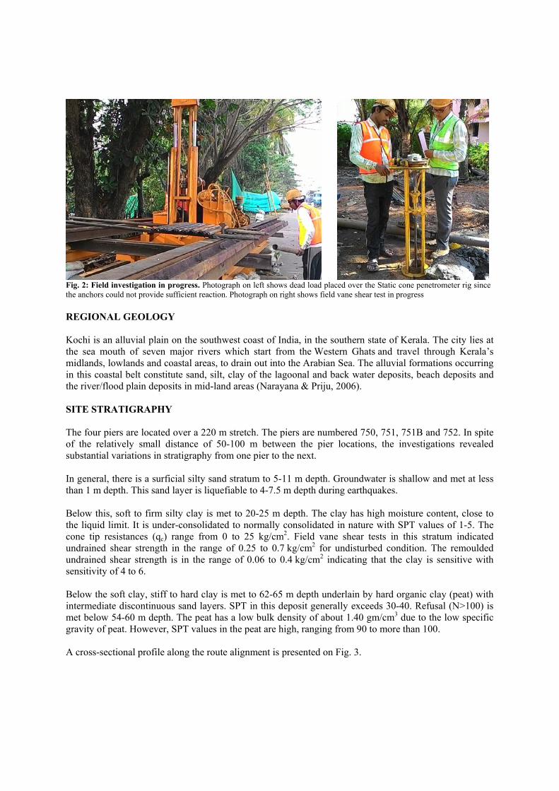
Fig. 2: Field investigation in progress. Photograph on left shows dead load placed over the Static cone penetrometer rig since the anchors could not provide sufficient reaction. Photograph on right shows field vane shear test in progress REGIONAL GEOLOGY Kochi is an alluvial plain on the southwest coast of India, in the southern state of Kerala. The city lies at the sea mouth of seven major rivers which start from the Western Ghats and travel through Kerala’s midlands, lowlands and coastal areas, to drain out into the Arabian Sea. The alluvial formations occurring in this coastal belt constitute sand, silt, clay of the lagoonal and back water deposits, beach deposits and the river/flood plain deposits in mid-land areas (Narayana & Priju, 2006). SITE STRATIGRAPHY The four piers are located over a 220 m stretch. The piers are numbered 750, 751, 751B and 752. In spite of the relatively small distance of 50-100 m between the pier locations, the investigations revealed substantial variations in stratigraphy from one pier to the next. In general, there is a surficial silty sand stratum to 5-11 m depth. Groundwater is shallow and met at less than 1 m depth. This sand layer is liquefiable to 4-7.5 m depth during earthquakes. Below this, soft to firm silty clay is met to 20-25 m depth. The clay has high moisture content, close to the liquid limit. It is under-consolidated to normally consolidated in nature with SPT values of 1-5. The cone tip resistances (qc) range from 0 to 25 kg/cm2. Field vane shear tests in this stratum indicated undrained shear strength in the range of 0.25 to 0.7 kg/cm2 for undisturbed condition. The remoulded undrained shear strength is in the range of 0.06 to 0.4 kg/cm2 indicating that the clay is sensitive with sensitivity of 4 to 6. Below the soft clay, stiff to hard clay is met to 62-65 m depth underlain by hard organic clay (peat) with intermediate discontinuous sand layers. SPT in this deposit generally exceeds 30-40. Refusal (N>100) is met below 54-60 m depth. The peat has a low bulk density of about 1.40 gm/cm3 due to the low specific gravity of peat. However, SPT values in the peat are high, ranging from 90 to more than 100. A cross-sectional profile along the route alignment is presented on Fig. 3.

Fig. 3: Cross-Sectional Profile
Soil Characteristics at Each Pier Location The soil characteristics at each pier location were evaluated in detail to assess the safe pile capacity. Typical soil properties including N-values, cone tip resistance and undrained shear strength profiles at Piers 751 and 752 are presented on Figs. 4 and 5.
Fig. 4: Soil Characteristics at Pier 751
Pier 750 Pier 751 Pier 751B Pier 752

Fig. 5: Soil Characteristics at Pier 752
Engineering Characteristics of the Soft Clay The soft clay is under-consolidated to normally-consolidated. A typical consolidation test conducted on it is presented on Fig. 6. It is highly sensitive with significant loss of shear strength on remoulding. The sensitivity ranges from 4 to 6 as illustrated in Fig. 7.
Fig. 6: Typical Consolidation Test Results Fig. 7: Sensitivity versus Depth
FOUNDATION DESIGN Liquefaction Susceptibility Assessment As per IS: 1893 (Part-1) – 2002, the project area is in Earthquake Zone 3. The design parameters for liquefaction analysis used are as follows:

Earthquake magnitude on Richter scale : 6.0 Peak ground acceleration : 0.16g Design Groundwater level : at ground level Silt content in shallow fine sand layer : 3-5% The liquefaction susceptibility assessment was performed as per the Summary Report of NCEER (Youd and Idris, 2001). The results are summarized in Table 1. Table 1: Assessment of Liquefaction Susceptibility
Pier Liquefaction Susceptibility Assessment 750 Liquefaction potential between 1.5-3.0 m depth751 Liquefaction potential to 4.5 m depth751B Liquefaction potential to 5.0 m depth752 Liquefaction potential to 5-7.5 m depth Pile Capacities RCC bored cast in-situ piles of 1500 mm diameter were planned to be used to support the piers. As per the design, the downward compression load on each pile was about 600 tonnes. The soft clay stratum is encountered at the pier locations from 5 to 8 m and from 18 to 24 m depths at Piers P-751, P-751B and P-752. At Pier P-750 location, the soft stratum is encountered between about 14 m and 30 m depth. In these depth zones, negative skin friction / downdrag has been considered on the piles. Based on the analysis, safe pile capacities for 1500 mm diameter bored cast-in-situ piles with cut-off level at 3 m depth computed in accordance with IS 2911 (Part 1/Section 2): 2010 are summarized in Table 2 below. The values include a factor of 2.5 under compression load and 3.0 for uplift. Table 2: Computed Safe Pile Capacities – 1500 mm diameter Bored Piles
Pier Pile Length below COL,
m
Computed Safe Pile Capacities, Tonnes
Magnitude of Negative Skin Friction (in ultimate
capacity), Tonnes Remarks
Compression (FS=2.5)
Uplift (FS=3.0)
Pier P750
50 430 277 81.5
Pile tip in hard clay 53 646 307 Pile tip in dense sand
Pier P751
52 561 281 96.8
Pile Tip in dense sand 55 611 310
Pier P751
B
65 585 380 71.3
Sand zones not met. Pile tip in hard clay 70 646 418
Pier P752
66 564 369 61.1
Sand zones not met. Pile tip in hard clay 71 622 406
The piling system has been designed using the above capacities. As may be seen in the above table, the pile tip level has to be decided depending upon the bearing strata. Where thick sand zones are met, pile length is relatively less.

The negative skin friction is a long-term phenomenon and will not be mobilized during the load test on the test pile which is usually conducted over a 36 to 48 hour period. To ensure that the piles are safe under the design loads, the applied load on the test pile has to be at least equal to twice the design load plus the magnitude of negative skin friction. CONCLUDING REMARKS The design of piles in strata containing soft clay requires a detailed and thorough geotechnical investigation. The routine boreholes have to be supplemented with static cone penetration tests and field vane shear tests to characterize the soils properly and evaluate the shear strength. The design may then be optimized after assessing the thickness of the zone that may experience negative skin friction. Pile load tests should consider the influence of negative skin friction on the test results. REFERENCES Narayana, A.C, and Priju, C.P. 2006. Evolution of coastal landforms and sedimentary environment of the late Quaternary period along Central Kerala, southwest coast of India. Journal of Coastal Research, Special Issue 39. Proceedings, 8th International Coastal Symposium, Brazil, 2004. pp 1898-1902. IS 1893 (Part-1): 2002. Indian Standard Criteria for Earthquake Design of Structures, Part 1: General Provisions and Buildings. 5th revision. Bureau of Indian Standards, New Delhi. Youd, T.L., and Idriss, I.M. 2001. Liquefaction Resistance of Soils: Summary Report from the 1996 NCEER and 1998 NCEER/NSF Workshops on Evaluation of Liquefaction Resistance of Soils. Journal of Geotechnical and Geo-environmental Engineering, April 2001. pp 297-313. IS 2911 (Part 1/Section 2): 2010. Indian Standard. Design and Construction of Pile Foundations – Code of Practice. Part 1 Concrete Piles. Section 2 Bored Cast-in Situ Concrete Piles. 2nd revision. Bureau of Indian Standards, New Delhi.