PiFace Digital I/O Documentation - Read the Docs · PiFace Digital I/O Documentation, Release 3.1.0...
25
PiFace Digital I/O Documentation Release 3.1.0 Thomas Preston Oct 08, 2017
Transcript of PiFace Digital I/O Documentation - Read the Docs · PiFace Digital I/O Documentation, Release 3.1.0...

PiFace Digital I/O DocumentationRelease 3.1.0
Thomas Preston
Oct 08, 2017

Contents
1 PiFace Digital 31.1 Outputs . . . . . . . . . . . . . . . . . . . . . . . . . . . . . . . . . . . . . . . . . . . . . . . . . . 31.2 Inputs . . . . . . . . . . . . . . . . . . . . . . . . . . . . . . . . . . . . . . . . . . . . . . . . . . . 4
2 Installation 52.1 Emulator . . . . . . . . . . . . . . . . . . . . . . . . . . . . . . . . . . . . . . . . . . . . . . . . . 5
3 Examples 73.1 Basic usage . . . . . . . . . . . . . . . . . . . . . . . . . . . . . . . . . . . . . . . . . . . . . . . . 73.2 Interrupts . . . . . . . . . . . . . . . . . . . . . . . . . . . . . . . . . . . . . . . . . . . . . . . . . 8
4 Simple Web Control 114.1 Controlling Output . . . . . . . . . . . . . . . . . . . . . . . . . . . . . . . . . . . . . . . . . . . . 114.2 Changing Port . . . . . . . . . . . . . . . . . . . . . . . . . . . . . . . . . . . . . . . . . . . . . . 11
5 Reference 13
6 Indices and tables 17
Python Module Index 19
i

ii
PiFace Digital I/O Documentation, Release 3.1.0
The pifacedigitalio Python module provides functions and classes for interacting with PiFace Digital.
Links:
• Blog
• GitHub
• PyPI
Contents:
Contents 1

PiFace Digital I/O Documentation, Release 3.1.0
2 Contents
CHAPTER 1
PiFace Digital
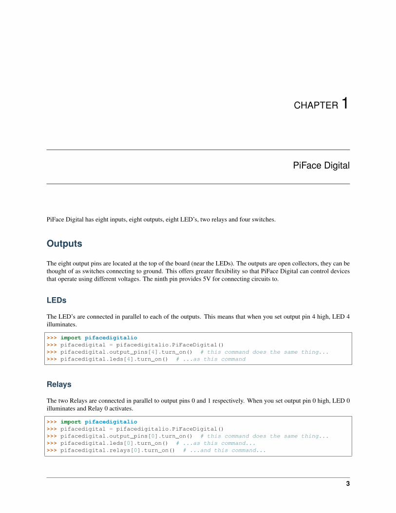
PiFace Digital has eight inputs, eight outputs, eight LED’s, two relays and four switches.
Outputs
The eight output pins are located at the top of the board (near the LEDs). The outputs are open collectors, they can bethought of as switches connecting to ground. This offers greater flexibility so that PiFace Digital can control devicesthat operate using different voltages. The ninth pin provides 5V for connecting circuits to.
LEDs
The LED’s are connected in parallel to each of the outputs. This means that when you set output pin 4 high, LED 4illuminates.
>>> import pifacedigitalio>>> pifacedigital = pifacedigitalio.PiFaceDigital()>>> pifacedigital.output_pins[4].turn_on() # this command does the same thing...>>> pifacedigital.leds[4].turn_on() # ...as this command
Relays
The two Relays are connected in parallel to output pins 0 and 1 respectively. When you set output pin 0 high, LED 0illuminates and Relay 0 activates.
>>> import pifacedigitalio>>> pifacedigital = pifacedigitalio.PiFaceDigital()>>> pifacedigital.output_pins[0].turn_on() # this command does the same thing...>>> pifacedigital.leds[0].turn_on() # ...as this command...>>> pifacedigital.relays[0].turn_on() # ...and this command...
3

PiFace Digital I/O Documentation, Release 3.1.0
When activated, the relay bridges the top and middle pins. When deactivated the bottom two are connected.
Relay activated:
[Top Pin ][Common ]Bottom Pin
Relay Deactivated:
Top Pin[Common ][Bottom Pin]
Inputs
The eight input pins detect a connection to ground (provided as the ninth pin). The four switches are connected inparallel to the first four input pins. The inputs are pulled up to 5V. This can be turned off so that the inputs float.
>>> import pifacedigitalio>>> pifacedigital = pifacedigitalio.PiFaceDigital()>>>>>> # without anything pressed>>> pifacedigital.input_port.value0>>> pifacedigital.input_pins[0].value0>>> pifacedigital.switches[0].value0>>>>>> # pressing the third switch>>> pifacedigital.input_port.value8>>> bin(pifacedigital.input_port.value)0b100>>> pifacedigital.input_pins[2].value # this command is the same as...1>>> pifacedigital.switches[2].value # ...this command1
4 Chapter 1. PiFace Digital

CHAPTER 2
Installation
Make sure you are using the lastest version of Raspbian:
$ sudo apt-get update$ sudo apt-get upgrade
Install pifacedigitalio (for Python 3 and 2) with the following command:
$ sudo apt-get install python{,3}-pifacedigitalio
Test by running the blink.py program:
$ python3 /usr/share/doc/python3-pifacedigitalio/examples/blink.py
Emulator
Install python3-pifacedigital-emulator with the following command:
$ sudo apt-get install python3-pifacedigital-emulator
Start the emulator with:
$ pifacedigital-emulator
Note: You must be in an X11 session (startx).
5

PiFace Digital I/O Documentation, Release 3.1.0
6 Chapter 2. Installation

CHAPTER 3
Examples
Basic usage
>>> import pifacedigitalio
>>> pfd = pifacedigitalio.PiFaceDigital() # creates a PiFace Digtal object
>>> pfd.leds[1].turn_on() # turn on/set high the second LED>>> pfd.leds[1].set_high() # turn on/set high the second LED>>> pfd.leds[2].toggle() # toggle third LED>>> pfd.switches[3].value # check the logical status of switch30>>> pfd.relays[0].value = 1 # turn on/set high the first relay
>>> pfd.output_pins[6].value = 1>>> pfd.output_pins[6].turn_off()
>>> pfd.input_pins[6].value0
>>> pfd.output_port.all_off()>>> pfd.output_port.value = 0xAA>>> pfd.output_port.toggle()
>>> bin(pfd.input_port.value) # fourth switch pressed (logical input port)'0b1000'
>>> bin(pfd.gpiob.value) # fourth switch pressed (physical input port)'0b11110111'
>>> pfd.deinit_board() # disables interrupts and closes the file
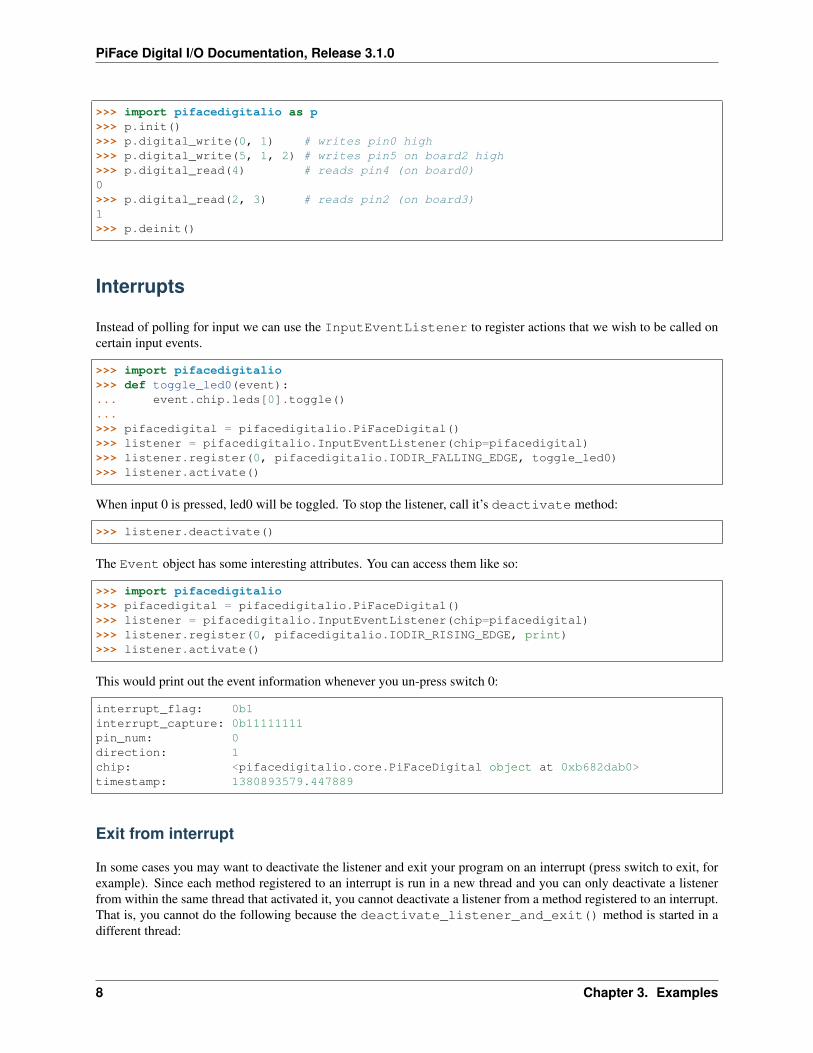
Here are some functions you might want to use if objects aren’t your thing:
7
PiFace Digital I/O Documentation, Release 3.1.0
>>> import pifacedigitalio as p>>> p.init()>>> p.digital_write(0, 1) # writes pin0 high>>> p.digital_write(5, 1, 2) # writes pin5 on board2 high>>> p.digital_read(4) # reads pin4 (on board0)0>>> p.digital_read(2, 3) # reads pin2 (on board3)1>>> p.deinit()
Interrupts
Instead of polling for input we can use the InputEventListener to register actions that we wish to be called oncertain input events.
>>> import pifacedigitalio>>> def toggle_led0(event):... event.chip.leds[0].toggle()...>>> pifacedigital = pifacedigitalio.PiFaceDigital()>>> listener = pifacedigitalio.InputEventListener(chip=pifacedigital)>>> listener.register(0, pifacedigitalio.IODIR_FALLING_EDGE, toggle_led0)>>> listener.activate()
When input 0 is pressed, led0 will be toggled. To stop the listener, call it’s deactivate method:
>>> listener.deactivate()
The Event object has some interesting attributes. You can access them like so:
>>> import pifacedigitalio>>> pifacedigital = pifacedigitalio.PiFaceDigital()>>> listener = pifacedigitalio.InputEventListener(chip=pifacedigital)>>> listener.register(0, pifacedigitalio.IODIR_RISING_EDGE, print)>>> listener.activate()
This would print out the event information whenever you un-press switch 0:
interrupt_flag: 0b1interrupt_capture: 0b11111111pin_num: 0direction: 1chip: <pifacedigitalio.core.PiFaceDigital object at 0xb682dab0>timestamp: 1380893579.447889
Exit from interrupt
In some cases you may want to deactivate the listener and exit your program on an interrupt (press switch to exit, forexample). Since each method registered to an interrupt is run in a new thread and you can only deactivate a listenerfrom within the same thread that activated it, you cannot deactivate a listener from a method registered to an interrupt.That is, you cannot do the following because the deactivate_listener_and_exit() method is started in adifferent thread:
8 Chapter 3. Examples
PiFace Digital I/O Documentation, Release 3.1.0
import sysimport pifacedigitalio
listener = None
def deactivate_listener_and_exit(event):global listenerlistener.deactivate()sys.exit()
pifacedigital = pifacedigitalio.PiFaceDigital()listener = pifacedigitalio.InputEventListener(chip=pifacedigital)listener.register(0,
pifacedigitalio.IODIR_FALLING_EDGE,deactivate_listener_and_exit)
listener.activate()
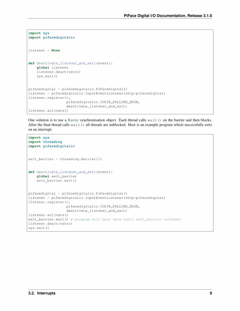
One solution is to use a Barrier synchronisation object. Each thread calls wait() on the barrier and then blocks.After the final thread calls wait() all threads are unblocked. Here is an example program which successfully exitson an interrupt:
import sysimport threadingimport pifacedigitalio
exit_barrier = threading.Barrier(2)
def deactivate_listener_and_exit(event):global exit_barrierexit_barrier.wait()
pifacedigital = pifacedigitalio.PiFaceDigital()listener = pifacedigitalio.InputEventListener(chip=pifacedigital)listener.register(0,
pifacedigitalio.IODIR_FALLING_EDGE,deactivate_listener_and_exit)
listener.activate()exit_barrier.wait() # program will wait here until exit_barrier releaseslistener.deactivate()sys.exit()
3.2. Interrupts 9

PiFace Digital I/O Documentation, Release 3.1.0
10 Chapter 3. Examples

CHAPTER 4
Simple Web Control
You can control PiFace Digital from a web browser (or any network enabled device) using the simplewebcontrol.pytool.
You can start the tool by running the following command on your Raspberry Pi:
$ python3 /usr/share/doc/python3-pifacedigitalio/examples/simplewebcontrol.py
This will start a simple web server on port 8000 which you can access using a web browser.
Type the following into the address bar of a browser on any machine in the local network:
http://192.168.1.3:8000
Note: Relace 192.168.1.3 with the IP address of your Raspberry Pi.
It will return a JSON object describing the current state of PiFace Digital:
{'input_port': 0, 'output_port': 0}
Controlling Output
You can set the output port using the URL:
http://192.168.1.61:8000/?output_port=0xaa
Changing Port
You can specify which port you would like simplewebcontrol.py to use by passing the port number as the firstargument:
11

PiFace Digital I/O Documentation, Release 3.1.0
$ python3 /usr/share/doc/python3-pifacedigitalio/examples/simplewebcontrol.py 12345
12 Chapter 4. Simple Web Control
CHAPTER 5
Reference
Note: Functions and classes in pifacedigitalio.core have been imported into the main namespace.pifacedigitalio.digital_write() is the same as pifacedigitalio.core.digital_write().
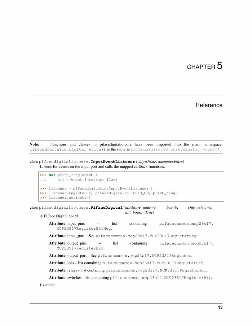
class pifacedigitalio.core.InputEventListener(chip=None, daemon=False)Listens for events on the input port and calls the mapped callback functions.
>>> def print_flag(event):... print(event.interrupt_flag)...>>> listener = pifacedigitalio.InputEventListener()>>> listener.register(0, pifacedigitalio.IODIR_ON, print_flag)>>> listener.activate()
class pifacedigitalio.core.PiFaceDigital(hardware_addr=0, bus=0, chip_select=0,init_board=True)
A PiFace Digital board.
Attribute input_pins – list containing pifacecommon.mcp23s17.MCP23S17RegisterBitNeg.
Attribute input_port – See pifacecommon.mcp23s17.MCP23S17RegisterNeg.
Attribute output_pins – list containing pifacecommon.mcp23s17.MCP23S17RegisterBit.
Attribute output_port – See pifacecommon.mcp23s17.MCP23S17Register.
Attribute leds – list containing pifacecommon.mcp23s17.MCP23S17RegisterBit.
Attribute relays – list containing pifacecommon.mcp23s17.MCP23S17RegisterBit.
Attribute switches – list containing pifacecommon.mcp23s17.MCP23S17RegisterBit.
Example:
13
PiFace Digital I/O Documentation, Release 3.1.0
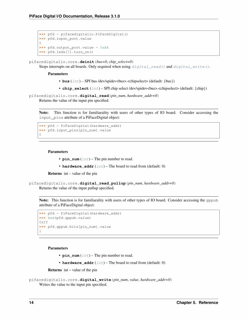
>>> pfd = pifacedigitalio.PiFaceDigital()>>> pfd.input_port.value0>>> pfd.output_port.value = 0xAA>>> pfd.leds[5].turn_on()
pifacedigitalio.core.deinit(bus=0, chip_select=0)Stops interrupts on all boards. Only required when using digital_read() and digital_write().
Parameters
• bus (int) – SPI bus /dev/spidev<bus>.<chipselect> (default: {bus})
• chip_select (int) – SPI chip select /dev/spidev<bus>.<chipselect> (default: {chip})
pifacedigitalio.core.digital_read(pin_num, hardware_addr=0)Returns the value of the input pin specified.
Note: This function is for familiarality with users of other types of IO board. Consider accessing theinput_pins attribute of a PiFaceDigital object:
>>> pfd = PiFaceDigital(hardware_addr)>>> pfd.input_pins[pin_num].value0
Parameters
• pin_num (int) – The pin number to read.
• hardware_addr (int) – The board to read from (default: 0)
Returns int – value of the pin
pifacedigitalio.core.digital_read_pullup(pin_num, hardware_addr=0)Returns the value of the input pullup specified.
Note: This function is for familiarality with users of other types of IO board. Consider accessing the gppubattribute of a PiFaceDigital object:
>>> pfd = PiFaceDigital(hardware_addr)>>> hex(pfd.gppub.value)0xff>>> pfd.gppub.bits[pin_num].value1
Parameters
• pin_num (int) – The pin number to read.
• hardware_addr (int) – The board to read from (default: 0)
Returns int – value of the pin
pifacedigitalio.core.digital_write(pin_num, value, hardware_addr=0)Writes the value to the input pin specified.
14 Chapter 5. Reference

PiFace Digital I/O Documentation, Release 3.1.0
Note: This function is for familiarality with users of other types of IO board. Consider accessing theoutput_pins attribute of a PiFaceDigital object:
>>> pfd = PiFaceDigital(hardware_addr)>>> pfd.output_pins[pin_num].value = 1
Parameters
• pin_num (int) – The pin number to write to.
• value (int) – The value to write.
• hardware_addr (int) – The board to read from (default: 0)
pifacedigitalio.core.digital_write_pullup(pin_num, value, hardware_addr=0)Writes the value to the input pullup specified.
Note: This function is for familiarality with users of other types of IO board. Consider accessing the gppubattribute of a PiFaceDigital object:
>>> pfd = PiFaceDigital(hardware_addr)>>> hex(pfd.gppub.value)0xff>>> pfd.gppub.bits[pin_num].value = 1
Parameters
• pin_num (int) – The pin number to write to.
• value (int) – The value to write.
• hardware_addr (int) – The board to read from (default: 0)
15

PiFace Digital I/O Documentation, Release 3.1.0
16 Chapter 5. Reference
CHAPTER 6
Indices and tables
• genindex
• modindex
• search
17

PiFace Digital I/O Documentation, Release 3.1.0
18 Chapter 6. Indices and tables
Python Module Index
ppifacedigitalio.core, 13
19

PiFace Digital I/O Documentation, Release 3.1.0
20 Python Module Index

Index
Ddeinit() (in module pifacedigitalio.core), 14digital_read() (in module pifacedigitalio.core), 14digital_read_pullup() (in module pifacedigitalio.core), 14digital_write() (in module pifacedigitalio.core), 14digital_write_pullup() (in module pifacedigitalio.core),
15
IInputEventListener (class in pifacedigitalio.core), 13
PPiFaceDigital (class in pifacedigitalio.core), 13pifacedigitalio.core (module), 13
21