Piezoelectric Effect Piezo Techlology Tutorial PI Ceramic
39
Piezo Technology l o n g L P E V GND P E P E P E P E V GND P E P E P E P E 2,5 1,5 2,0 0,5 1,0 0,0 1500 1000 500 2000 0 E PP [kV/mm] d ( G S ) [ p m / V ] d 15 PIC155 bipolar d 15 PIC255 bipolar d 33 PIC153 unipolar d 33 PIC151 unipolar d 33 PIC255 unipolar d 33 PIC252 unipolar -d 31 PIC252 unipolar (1) (2) O 2 Pb Ti, Zr 4( %æ0)%:/ %, %#42)#æ%&&%#4 PI E z O t E Ch nO l O g y
-
Upload
sarli-kinanti -
Category
Documents
-
view
223 -
download
2
Transcript of Piezoelectric Effect Piezo Techlology Tutorial PI Ceramic

7/28/2019 Piezoelectric Effect Piezo Techlology Tutorial PI Ceramic
http://slidepdf.com/reader/full/piezoelectric-effect-piezo-techlology-tutorial-pi-ceramic 1/38
Piezo Technology
l o n g
L
P EV
GND
P E
P E
P E
P EV GND
P E
P E
P E
P E
2,51,5 2,00,5 1,00,0
1500
1000
500
2000
0
EPP [kV/mm]
d ( G S )
[ p m / V ]
d15
PIC155 bipolar
d15
PIC255 bipolar
d33
PIC153 unipolar
d33
PIC151 unipolar
d33
PIC255 unipolar
d33 PIC252 unipolar
-d31
PIC252 unipolar
(1)
(2)
O2
Pb
Ti, Zr
4( %æ0)%:/ %, %#42)#æ%&&%#4
P I E z O t E Ch nO l O g y

7/28/2019 Piezoelectric Effect Piezo Techlology Tutorial PI Ceramic
http://slidepdf.com/reader/full/piezoelectric-effect-piezo-techlology-tutorial-pi-ceramic 2/38
4
w w w . P I C ER A M I C . C O M
Piezo TechnologyCOntEnts
Basic Principles o Piezoelectricity 35
Piezoelectric Eect, Ferroelectric Polarization, Expansion o the Polarized
Piezo Ceramic
Piezoelectric Actuator Materials 36
Piezoceramic Materials and Properties
Displacement Modes o Piezoelectric Actuators 37
Longitudinal Stack Actuators 37 – Shear Actuators, Picoactuator® 38
PT-Tube Tube Actuators 39 – Contracting Actuators 40 – Bending Actuators 41
Manuacturing o Piezo Actuators 42
Multilayer Tape Technology 42 – Pressing Technology 43
PT-Tube Tube Actuators, DuraAct 44
Properties o Piezoelectric Actuators 45
Displacement Behavior 45
Nonlinearity 45 – Hysteresis, Creep 46 – Position Control 47
Temperature-Dependent Behavior 48
Forces and Stinesses 50
Preload, Load Capacity, Stiness 50 – Force Generation and Displacement,
Typical Load Cases 51 – Actuator Dimensioning and Energy Consideration 53
Dynamic Operation 54
Resonant Frequency, How Fast Can a Piezo Actuator Expand?, Dynamic Forces
Electrical Operation 55
Electrical Behavior, Electrical Capacitance, Positioning Operation 55 – PowerConsumption o the Piezo Actuator, Heat Generation in the Piezo Element, Continuous
Dynamic Operation 56 Switching Applications, Pulse-Mode Operation 57
Ambient Conditions 58
Vacuum Environment, Inert Gases, Magnetic Fields, Gamma Radiation,
Environments with High Humidity, Liquids
Reliability o PICMA® Multilayer Actuators 59
Lietime when Exposed to DC-Voltage 59 – Lietime in Dynamic Continuous
Operation 60
Amplifer Technology: Piezo Electronics or Operating Piezo Actuators 61
Characteristic Behavior o Piezo Amplifers 61
Power Requirements or Piezo Operation, Amplier Frequency Response Curve,
Setting the Control Input Voltage
Solutions or High-Dynamics 24/7 Operation . . . . . . . . . . . . . . . . . . . . . . . . . . . . . . . . . . 62
Switched Ampliers with Energy Recovery, Piezo Overtemperature Protection,
Valid Patents 62 – Linearized Ampliers or Piezo Displacement Without Hysteresis,
Charge Control, Charge and Displacement 63
Handling o Piezo Actuators 64
Mechanical Installation 64 – Electrical Connection, Sae Operation 65

7/28/2019 Piezoelectric Effect Piezo Techlology Tutorial PI Ceramic
http://slidepdf.com/reader/full/piezoelectric-effect-piezo-techlology-tutorial-pi-ceramic 3/38

7/28/2019 Piezoelectric Effect Piezo Techlology Tutorial PI Ceramic
http://slidepdf.com/reader/full/piezoelectric-effect-piezo-techlology-tutorial-pi-ceramic 4/38

7/28/2019 Piezoelectric Effect Piezo Techlology Tutorial PI Ceramic
http://slidepdf.com/reader/full/piezoelectric-effect-piezo-techlology-tutorial-pi-ceramic 5/38
3
P I E z O t E Ch nO l O g y
Longitudinal Stack Actuators
In longitudinal piezo actuators, the electric
eld in the ceramic layer is applied parallel
to the direction o polarization This induces
an expansion or displacement in the di-
rection o polarization Individual layers pro-
vide relatively low displacements In order
to achieve technically useul displacement
values, stack actuators are constructed,
where many individual layers are mecha-nically connected in series and electrically
connected in parallel (g 5)
Longitudinal stack actuators are highly
ecient in converting electrical to mechani-
cal energy They achieve nominal displace-
ments o around 01 to 015% o the actua-
tor length The nominal blocking orces are
on the order o 30 N/mm2 in relation to the
cross-sectional area o the actuator Values
o up to several 10,000 newton can thus be
achieved in the actuator
Longitudinal stack actuators are excellently
suited or highly dynamic operation due to
their high resonant requencies A mecha-
nical preloading o the actuator suppresses
dynamically induced tensile orces in
brittle ceramic material, allowing response
times in the microsecond range and a high
mechanical perormance
In addition to the expansion in the di-
rection o polarization, which is utilized
with longitudinal actuators, a contraction
always occurs in the piezo actuator that
is orthogonal to its polarization when it
is operated with an electric eld parallel
to the direction o polarization
This so-called transversal piezoelectric
eect is used by contracting actuators,
tube actuators, or bending actuators
Examples o longitudinal
stack actuators are the
multilayer piezo actuators
PICMA® Stack, Encapsu-
lated PICMA®, PICMA®
Chip, as well as the stack
actuators PICA Stack,
PICA Power, PICA Thru
that are glued together
rom individual plates,
and the crystalline Pico-
actuator®
ΔLlong
Longitudinal dis-
placement [m]
d33(GS)
Longitudinal
piezoelectric
large-signal deor-
mation coecient
[m/V]
n Number o
stacked ceramic
layers
V Piezo operating
voltage [V]
l o n g
L
P EV
GND
P E
P E
P E
P EV GND
P E
P E
P E
P E
Fig 5
ΔLlong
= n d33(GS)
V (Equation 1)
Piezoelectric Actuatorsd IsPlACEMEnt MOdEs

7/28/2019 Piezoelectric Effect Piezo Techlology Tutorial PI Ceramic
http://slidepdf.com/reader/full/piezoelectric-effect-piezo-techlology-tutorial-pi-ceramic 6/38
8
w w w . P I C ER A M I C . C O M
Shear Actuators
In piezoelectric shear actuators, the electric
eld in the ceramic layer is applied orthogo-
nally to the direction o polarization and the
displacement in the direction o polarization
is utilized The displacements o the indivi-
dual layers add up in stacked actuators here
as well (g 6)
The shear deormation coecients d15
are
normally the largest piezoelectric coeci-
ents When controlled with nominal volta-
ges, PIC ceramics achieve d15(GS)
values o up
to 2000 pm/V The permissible controlling
eld strength is limited in order to prevent
a reversal o the vertically oriented polari-
zation
When lateral orces act on the actuator, the
shear motion is additionally superimposed
by a bending The same eect occurs in
dynamic operation near the resonant re-
quency
Furthermore, shear stresses cannot be com-
pensated by a mechanical preload Both,
limit the practical stacking height o shear
stacks
Shear actuators combined with longitudinal
actuators yield very compact XYZ stacks
with high resonant requencies
Picoactuator® Technology
Picoactuator® longitudinal and shear actua-
tors are made o the crystalline piezoelectricmaterial PIC 050 The specic displacement
is ±002% (shear actuators) or ±001% (lon-
gitudinal piezo actuators) o the actuator
length and is thus 10 times lower than or
classic piezo actuators made o lead zirco-
nate - lead titanate (PZT) The displacement
here is highly linear with a deviation o only
02%
Fig 6
ΔLshear
= n d15(GS)
V (Equation 2)
Lshear
V
GND EP
A typical application or
shear actuators are drive
elements or so-called
stick-slip motors
Shear actuators rom PI
Ceramic are oered as
product lines PICA Shear
and Picoactuator
Fig 7:
Measured Nonlinearity o a Picoactuator®
Displacement Modes (Continued)
V GND
E
E
E
E
E
E
E
E
P
P
P
P
P
P
P
P

7/28/2019 Piezoelectric Effect Piezo Techlology Tutorial PI Ceramic
http://slidepdf.com/reader/full/piezoelectric-effect-piezo-techlology-tutorial-pi-ceramic 7/38

7/28/2019 Piezoelectric Effect Piezo Techlology Tutorial PI Ceramic
http://slidepdf.com/reader/full/piezoelectric-effect-piezo-techlology-tutorial-pi-ceramic 8/38
0
Contracting Actuators
Typically, piezo contracting actuators are
low-prole components Their displacement
occurs perpendicularly to the polarization
direction and to the electric eld The dis-
placement o contracting actuators is based
on the transversal piezoelectric eect whe-
reby up to approx 20 µm is nominally achie-
ved
Multilayer elements oer decisive advan-
tages over single-layer piezo elements in
regard to technical realization: Due to the
larger cross-sectional area, they generatehigher orces and can be operated with a
lower voltage (g 11)
As a result o the contraction, tensile stres-
ses occur that can cause damage to the
brittle piezo ceramic A preload is thereore
recommended
For the patch actuators o the DuraAct pro-
duct group, a piezo contractor is laminated
into a polymer This creates a mechanical
preload that protects the ceramic againstbreakage (p 14)
Multilayer contracting actuators can be re-
quested as special versions o the PICMA®
Bender product line (p 13)
Fig 11
ΔLtrans
= d31 (GS)
l V (Equation 6)
h
ΔLtrans
E
E
E
E
P
P
P
P
GND V
EP
V
GND
i_ _ill i _ i .i . .
Displacement Modes (Continued)
w w w . P I C ER A M I C . C O M
ΔLtrans
Transversal dis-
placement [m]
d31(GS)
Transversal piezo-
electric large-sig-
nal deormation
coecient [m/V]
l Length o the
piezo ceramic in
the direction o
displacement [m]
h Height o a
ceramic layer [m]
n Number o
stacked ceramic
layers
V Piezo operating
voltage [V]
ΔLbend
Bending displace-
ment [m]
lf
Free bender
length [m] (p 12)
hp
Height piezo-
ceramic element
[m]
Rh
Ratio o the
heights o the
substrate (hs)
and piezoceramic
element (hp) in a
composite bender
(Rh=h
s /h
p)
RE
Ratio o the elas-
ticity modulus o
the substrate (Es)
and the piezocera-mic element (E
p)
in a composite
bender (RE=E
s /E
p)
V F
Fixed voltage or
bender actuator
control [V] (V and
VF
can be super-
imposed with an
oset voltage)
E
E
P
P
lf
hP
i_1 137_illu_ .in 1 . .1 1 :

7/28/2019 Piezoelectric Effect Piezo Techlology Tutorial PI Ceramic
http://slidepdf.com/reader/full/piezoelectric-effect-piezo-techlology-tutorial-pi-ceramic 9/38

7/28/2019 Piezoelectric Effect Piezo Techlology Tutorial PI Ceramic
http://slidepdf.com/reader/full/piezoelectric-effect-piezo-techlology-tutorial-pi-ceramic 10/38 w w w . P I C ER A M I C . C O M
The more ne-grained the ceramic materi-
al used, the thinner the multiple layers that
can be produced In PICMA® Stack actua-
tors, the height o the active layers is 60 µm
and in PICMA® Bender actuators around 20
to 30 µm, so that the benders can be opera-
ted with a very low nominal voltage o only
60 V
Multilayer Tape Technology
The technologies or manuacturing pi-
ezo actuators decisively contribute to
their unction, quality and eciency
PI Ceramic is procient in a wide range o
technologies, rom multilayer tape techno-
logy or PICMA® stack and bending actua-
tors, through glued stack actuators or lon-
gitudinal and shear displacements, up to the
construction o crystalline Picoactuator® ac-
tuators, the DuraAct patch transducers and
piezoceramic tubes
PI Ceramic multilayer actuators, PICMA® or
short, are manuactured in large batches
with tape technology First, the inner elec-
trode pattern is printed on thin PZT tapes
while still unsintered and these are then
laminated into a multilayer compound In
the subsequent coring process, the cera-
mic and the inner electrodes are sintered
together The nished monolithic multilayer
piezo element has no polymer content any-
more
The inner electrodes o all PICMA® actuatorsare ceramically insulated (g 19) PICMA®
stack actuators use a patented structure
or this purpose, in which a thin ceramic in-
sulation tape covers the electrodes without
signicantly limiting the displacementFinal inspection
Assembly
Polarization
Application o the termination electrodes
Grinding, lapping
Debindering and sintering (coring)
Cutting and green shaping
Isostatic pressing
Stacking, laminating
Screen printing o the inner electrodes
Tape casting
Slurry preparation
Processing o the
piezo ceramic powder
Multilayer Tape Technology
Fig 19: In PICMA® stack actuators, a
ceramic insulation tape covers the
inner electrodes
Hermetically encapsulated PICMA® were developed
or applications in extremely high humidity and in
rough industrial environments They are equippedwith corrosion-resistant stainless-steel bellows, inert
gas lling, glass eedthroughs and laser welding
PICMA® multilayer actuators are produced in dierent shapesDepending on the application, they can also be
assembled with adapted ceramic or metal end pieces, additional coating, temperature sensors, etc
In the past years, the technologies or processing
actuators in an unsintered state have been conti-
nuously developed For this reason, round geometriesor PICMA® actuators with an inner hole can also be
manuactured
OF P I EzO ACtuAtORs
Manufacturing

7/28/2019 Piezoelectric Effect Piezo Techlology Tutorial PI Ceramic
http://slidepdf.com/reader/full/piezoelectric-effect-piezo-techlology-tutorial-pi-ceramic 11/38
4
P I E z O t E Ch nO l O g y
other processing and mounting steps are
similar to those or stacked PICA actuators
Pressing Technology
PICA stack actuators such as PICA Stack,
Thru or Shear consist o thin piezoceramic
plates with a standard layer thickness o
05 mm For manuacturing, piezoceramic
cylinders or blocks are shaped with pressing
technology, sintered and then separated
into plates with diamond waer saws Me-
tal electrodes are attached with thin or thick
lm methods depending on the material,
and the ceramic is then polarized
Stack actuators are created by gluing the pla-
tes together whereby a thin metal contact pla-
te is placed between each two ceramic plates
in order to contact the attached electrodes
The contact plates are connected with each
other in a soldering step, and the nished
stack is then covered with a protective poly-
mer layer and possibly an additional shrink
tubing
Picoactuator® piezo actuators consist o
crystalline layers with a thickness o 038
mm In contrast to ceramic, the orientation
o the spontaneous polarization is not deter-mined by a erroelectric polarization but by
the cutting direction in the monocrystal AllFinal inspection
Mounting and assembling technology:
Gluing, poss ultrasonic drilling or inner
hole, soldering, coating
Polarization
Application o electrodes by
screen printing or sputtering
Lapping, grinding, diamond slicing
Debindering and sintering
Pressing and shaping
Spray drying
Milling
Calcination, presintering
Mixing the raw materials
Pressing Technology
The nal processing o the piezoceramic plates manuactured with pressing technology is adapted to their
uture use The gure shows dierent piezo actuator modules
Completely assembled stack actuators with a metalendpiece and SGS expansion sensor (let), with stran-ded wires, temperature sensor and transparent FEP
shrink tubing (right)

7/28/2019 Piezoelectric Effect Piezo Techlology Tutorial PI Ceramic
http://slidepdf.com/reader/full/piezoelectric-effect-piezo-techlology-tutorial-pi-ceramic 12/38
4
w w w . P I C ER A M I C . C O M
PT Tube Actuators
PT Tube actuators are manuactured rom
piezoceramic cylinders that were previous-
ly produced with the pressing technologyThe outer diameter and the parallelism o
the end-surace are precisely set through
centerless circular grinding and surace
grinding The inner hole is drilled with an
ultrasonic method
The metalization then is done with thin- or
thick-layer electrodes, possibly accompa-
nied by structuring o the electrodes with a
laser ablation method
In addition to the described procedure or
manuacturing precision tubes with very
narrow geometric tolerances, the more cost-ecient extrusion method is also available
or small diameters
Structured electrodes allow specic driving o tube actuators
Laminated ceramic layers in a DuraAct transducer
arrangement (array)
Dierent shapes o DuraAct actua-tors with ceramic plates in pressing
and multilayer technology
Manufacturing of Piezo Actuators (Continued)DuraAct Patch Actuators and Transducers
DuraAct patch actuators use piezoceramic
contracting plates as their base product De-
pending on the piezoceramic thickness, the-
se plates are manuactured with pressing
technology (>02 mm) or tape technology
(005 to 02 mm) The plates are connected
to orm a composite using conductive ab-
ric layers, positioning tapes, and polyimide
cover tapes
The lamination process is done in an auto-clave in a vacuum, using an injection me-
thod This results in completely bubble-ree
laminates o the highest quality
The curing temperature prole o the auto-
clave is selected so that a dened internal
preload o the piezoceramic plates will re-
sult due to the dierent thermal expansion
coecients o the materials involved
The result o this patented technology are
robust, bendable transducer elements that
can be manuactured in large batches

7/28/2019 Piezoelectric Effect Piezo Techlology Tutorial PI Ceramic
http://slidepdf.com/reader/full/piezoelectric-effect-piezo-techlology-tutorial-pi-ceramic 13/38
4
P I E z O t E Ch nO l O g y
Properties of Piezoelectric Actuatorsd IsPlACEMEnt bEhAV IOR
Nonlinearity
The voltage-dependent displacement curves
o piezo actuators have a strongly nonlinear
course that is subject to hysteresis due to the
extrinsic domain contributions It is there-
ore not possible to interpolate linearly rom
the nominal displacement to intermediate
positions with a particular driving voltage
The electromechanical and dielectric large-
signal curves o piezo ceramics illustrate thecharacteristics (g 20) The origin o each
graph is dened by the respective thermally
depolarized condition
The shape o both bipolar large-signal cur-
ves is determined by the erroelectric po-
larity reversal process when the coercive
eld strength EC
is achieved in the opposing
eld The dielectric curve shows the very
large polarization changes at these switch-
over points At the same time, the contrac-
tion o the ceramic ater reversing the po-
larity turns into an expansion again, since
the polarization and the eld strength havethe same orientation once more This pro-
perty gives the electromechanical curve its
characteristic butterfy shape Without the
electric eld, the remnant polarizations Prem
/-Prem
and the remnant strain Srem
remain
Piezo actuators are usually driven unipolar-
ly A semibipolar operation increases the
strain amplitude while causing a stronger
nonlinearity and hysteresis which result
rom the increasing extrinsic domain por-
tions o the displacement signal (g 21)
Fig 21: Unipolar and semibipolar electromechanical
curves o erroelectric piezo ceramics and denition
o the piezoelectric large-signal deormation coeci-
ent d(GS)
as the slope between the switchover points
o a partial hysteresis curve
E
S
ΔS
ΔE
P
Ec E-Ec
Prem
unipolar
semi-bipolar
bipolar
S
EEc
Srem
unipolar
semi-bipolar
bipolar
Fig 20: Displacement o erroelectric piezo ceramics with dierent control amplitudes parallel to the
direction o polarization direction Large-signal curves as a unction o the electrical eld strength E
a) electromechanical behavior o the longitudinal strain S, b) dielectric behavior o the polarization P
In the PI and PIC data
sheets, the ree displace-
ments o the actuators are
given at nominal voltage
Piezoelectric
Deormation Coefcient
(Piezo Modulus)
The gradient ΔS/ ΔE
between the two switch-
over points o the non-linear hysteresis curves
is dened as the piezo-
electric large-signal
deormation coecients
d(GS)
(g 21) As the
progressive course o
the curves shows, these
coecients normally
increase along with the
eld amplitude (g 22)
1,5 2,00,5 1,00,0
1500
1000
500
2000
0
EPP [kV/mm
d ( G S )
[ p m / V ]
d15
PIC155 bipolar
d15
PIC255 bipolar
d33
PIC153 unipolar
d33
PIC151 unipolar
d33
PIC255 unipolar
d33
PIC252 unipolar
-d31
PIC252 unipolar
Fig 22: Piezoelectric large-signal
deormation coecients d(GS)
or
dierent materials and control mo-
des at room temperature and with
quasistatic control With very small
eld amplitudes, the values o the
coecients match the material
constants on p 36
a) b)
d(GS)
= ΔS (Equation 11)
ΔE

7/28/2019 Piezoelectric Effect Piezo Techlology Tutorial PI Ceramic
http://slidepdf.com/reader/full/piezoelectric-effect-piezo-techlology-tutorial-pi-ceramic 14/38
6
w w w . P I C ER A M I C . C O M
Estimation o the Expected Displacement
I the values rom g 22 are entered into the equations 3 to 10 (p 39-41), the attainable displacement at a particular
piezo voltage can be estimated The eld strength can be calculated rom the layer heights o the specic component
and the piezo voltage VPP The layer thickness o the PI Ceramic standard products can be ound starting on p 42
The ree displacement o the components that can actually be attained depends on urther actors such as the mecha-
nical preload, the temperature, the control requency, the dimensions, and the amount o passive material
Hysteresis
In open-loop, voltage-controlled operation,
the displacement curves o piezo actuators
show a strong hysteresis (Fig 24) that usu-ally rises with an increasing voltage or eld
strength Especially high values result or
shear actuators or with bipolar control The
reason or these values is the increasing in-
volvement o extrinsic polarity reversal pro-
cesses in the overall signal
Creep
Creep describes the change in the displace-
ment over time with an unchanged drive
voltage The creep speed decreases loga-rithmically over time The same material
properties that are responsible or the hys-
teresis also cause the creep behavior:
Fig 23: The hysteresis
value Hdisp
is dened as the
ratio between the maximum
opening o the curve and themaximum displacement
ΔL
V
ΔLmax
Max Diff ΔL
2,51,5 2,00,5 1,00,0
40%
35%
30%
25%
10%
15%
20%
5%
0%
EPP[kV/mm]
H d i s p
d15
PIC155 bipolar
d15
PIC255 bipolar
d33
PIC151 unipolar
d33
PIC252/255 unipolar
d33
PIC153 unipolar
Fig 24: Displacement hysteresis Hdisp
o various
actuator materials in open-loop, voltage-controlled
operation or dierent drive modes at room tempe-
rature and with quasistatic control
Fig 25: Displacement o a piezo actuator when
driven with a sudden voltage change (step unction)
The creep causes approx 1% o the displacement
change per logarithmic decade
ΔL(t) ≈ ΔL
t = 0.1s1 +γ lg ( t ) (Equation 12)
0.1s
t Time [s]
ΔL(t) Displacement as
a unction o time
[m]
ΔLt=0.1s
Displacement at
01 seconds ater
the end o the
voltage change
[m]
γ Creep actor,
depends on thematerial proper-ties (approx 001
to 002, corres-ponds to 1% to 2%per decade)
Displacement Behavior (Continued)

7/28/2019 Piezoelectric Effect Piezo Techlology Tutorial PI Ceramic
http://slidepdf.com/reader/full/piezoelectric-effect-piezo-techlology-tutorial-pi-ceramic 15/38
4
P I E z O t E Ch nO l O g y
PI oers a wide range
o position-controlled
piezo systems with
capacitive sensors or
strain gauges When the
actuator and sensor are
combined with suitable
guiding mechanics, a
low-noise amplier and
corresponding control
algorithms, these sys-tems achieve positio-
ning accuracies in the
subnanometer range
wwwpiws
Position Control Hysteresis and creep o piezo actuators can
be eliminated the most eectively through
position control in a closed servo loop To
build position-controlled systems, the PI Ce-
ramic piezo actuators o the PICA Stack and
PICA Power product line can be optionally
oered with applied strain gauges
In applications with a purely dynamic con-
trol, the hysteresis can be eectively redu-
ced to values o 1 to 2% even with open-loop
control by using a charge-control amplier
(p 63)
Fig 26: Elimination o hysteresis and creep in a piezo
actuator through position control

7/28/2019 Piezoelectric Effect Piezo Techlology Tutorial PI Ceramic
http://slidepdf.com/reader/full/piezoelectric-effect-piezo-techlology-tutorial-pi-ceramic 16/38
8
w w w . P I C ER A M I C . C O M
Below the Curie temperature, the tempera-
ture dependance o the remnant strain and
the coercive eld strength is decisive or the
temperature behavior Both the attainable
displacement with electric operation and
the dimensions o the piezoceramic element
change depending on the temperature
The cooler the piezo actuator, the greater the
remnant strain Srem
and the coercive eld
strength Erem
(g 27) The curves become
increasingly fatter with decreasing tem-
peratures This causes the strain induced by
a unipolar control to become smaller and
smaller even though the total amplitude o
the bipolar strain curve hardly changes over
wide temperature ranges The lower the
temperature, the greater the remnant strain
All in all, the piezo ceramic has a negative
thermal expansion coecient, ie the
piezo ceramic becomes longer when it cools
down In comparison: A technical ceramic
contracts with a relatively low thermal
expansion coecient upon cooling This
surprising eect is stronger, the more
completely the piezo ceramic is polarized
Displacement as a Function o the
Temperature
How much a key parameter o the piezo
actuator changes with the temperature de-pends on the distance rom the Curie tem-
perature PICMA® actuators have a relatively
high Curie temperature o 350°C At high
operating temperatures, their displacement
only changes by the actor o 005%/K
S
EEc
Srem
S
EEc
Srem
EEc
S
Srem
1000100101
100%
80%
60%
40%
20%
0%
R e l a t i v e A u s l e n k u n g
Temperatur [K]
unipolar 0 bis 120 V
bipolar -120 bis 120 V
Fig 27: Bipolar electromechanical large-signal curve o piezo actuators at dierent temperatures From let: behavior at low temperatures, at room
temperature, at high temperatures
Fig 28: Relative decrease in the displacement using
the example o a PICMA® stack actuator in the
cryogenic temperature range with dierent piezo
voltages in relation to nominal displacement at room
temperature
Properties of Piezoelectric ActuatorstEMPERAtuRE -dEPEndEnt bEhAV IOR

7/28/2019 Piezoelectric Effect Piezo Techlology Tutorial PI Ceramic
http://slidepdf.com/reader/full/piezoelectric-effect-piezo-techlology-tutorial-pi-ceramic 17/38
4
P I E z O t E Ch nO l O g y
At cryogenic temperatures, the displace-
ment decreases When controlled uni-
polarly in the liquid-helium temperature
range, piezo actuators only achieve 10 to
15% o the displacement at room tempera-
ture Considerably higher displacements at
lower temperatures can be achieved with
a bipolar drive Since the coercive eld
strength increases with cooling (g 27),
it is possible to operate the actuator with
higher voltages, even against its polariza-
tion direction
Dimension as a Function o the
Temperature
The temperature expansion coecient o
an all-ceramic PICMA® stack actuator is ap-
proximately -25 ppm/K In contrast, the ad-
ditional metal contact plates as well as the
adhesive layers in a PICA stack actuator lead
to a nonlinear characteristic with a positive
total coecient (g 29)
I a nanopositioning system is operated in
a closed servo loop, this will eliminate tem-
perature drit in addition to the nonlinearity,
hysteresis, and creep The control reserve to
be kept or this purpose, however, reduces
the usable displacement
For this reason, the temperature drit is
oten passively compensated or by a suit-
able selection o the involved materials, the
actuator types, and the system design For
example, all-ceramic PICMA® bender actua-
tors show only a minimal temperature drit
in the displacement direction due to their
symmetrical structure
Temperature Operating Range
The standard temperature operating range
o glued actuators is -20 to 85°C Selecting
piezo ceramics with high Curie temperatu-
res and suitable adhesives can increase this
range Most PICMA® multilayer products
are specied or the extended range o -40
to 150°C With special solders, the tempera-
ture range can be increased so that special
models o PICMA® actuators can be used
between -271°C and 200°C, ie, over a range
o almost 500 K
-100 -80 -60 -40 -20 0 20 40 60 80 100
-0.06
-0.04
-0.02
0.02
0.04
0.06
0.08
0
Temp. [°C]
T h e r m a l s t r a i n [ % ]
E = 1 kV/mm
no preload
Measuring sequence
PICMA® Stack
PICA Stack / PICA Power
Fig 29: Temperature expansion behavior o PICMA® and PICA actuators with electric large-
signal control

7/28/2019 Piezoelectric Effect Piezo Techlology Tutorial PI Ceramic
http://slidepdf.com/reader/full/piezoelectric-effect-piezo-techlology-tutorial-pi-ceramic 18/38
0
w w w . P I C ER A M I C . C O M
Preload and Load Capacity
The tensile strengths o brittle piezo ceramic
and single-crystal actuators are relatively
low, with values in the range o 5 to 10 MPa
It is thereore recommended to mechanically
preload the actuators in the installation The
preload should be selected as low as possible
According to experience, 15 MPa is sucient
to compensate or dynamic orces (p 54); in
the case o a constant load, 30 MPa should not
be exceeded
Lateral orces primarily cause shearing
stresses in short actuators In longer ac-
tuators with a larger aspect ratio, bending
stresses are also generated The sum o
both loads yield the maximum lateral load
capacities that are given or the PICA shear
actuators in the data sheet (p 24) These
values can be transerred to actuators with a
similar geometry However, it is normally re-
commended to protect the actuators against
lateral orces by using guidings
Stiness
The actuator stiness kA
is an important
parameter or calculating orce generation,
resonant requency, and system behavior
Piezoceramic stack actuators are characte-
rized by very high stiness values o up to
several hundred newtons per micrometer
The ollowing equation is used or calcula-
tion:
Bending actuators, however, have sti-
nesses o a ew newtons per millimeter,
lower by several orders o magnitude In
addition to the geometry, the actuator sti-
ness also depends on the eective elasticity
module E* Because o the mechanical depo-
larization processes, the shape o the stress-
strain curves (g 30) is similarly nonlinear
and subject to hysteresis as are the electro-
mechanical curves (g 21) In addition, the
shape o the curve depends on the respecti-
ve electrical control conditions, the drive re-quency, and the mechanical preload so that
values in a range rom 25 to 60 GPa can be
measured As a consequence, it is dicult to
dene a generally valid stiness value
For speciying piezo actuators, the quasi-
static large-signal stiness is determined
with simultaneous control with a high eld
strength or voltage and low mechanical pre-
load As a result, an unavorable operating
case is considered, ie, the actual actuator
stiness in an application is oten higher
The adhesive layers in the PICA actuatorsonly reduce the stiness slightly By using
optimized technologies, the adhesive gaps
are only a ew micrometers high so that the
large-signal stiness is only approx 10 to
20% lower than that o multilayer actuators
without adhesive layers
The actuator design has a much stronger
infuence on the total stiness, eg spheri-
cal end piece with a relatively fexible point
contact to the opposite ace
Properties of Piezoelectric ActuatorsFORCEs And st I F FnEssEs
Limitations o the Preload
The actuator begins to mechanically depolarize at only a ew tens o MPa A large-signal control repolarizes the actu-
ator; on the one hand, this causes the induced displacement to increase but on the other hand, the eective capacity
and loss values increase as well, which is detrimental to the lietime o the component
A pressure preload also partially generates tensile stress (p 64) For this reason, when very high preloads are used,
the tensile strength can locally be exceeded, resulting in a possible reduction o lietime or damage to the actuator
The amount o the possible preload is not determined by the strength o the ceramic material Piezo actuators attain
compressive strengths o more than 250 MPa
kA Stack
= E* A (Equation 13)
l
E* Eective elasticity
module: linear
increase o a
stress-strain curve
o a sample body
or actuator made
o the correspon-
ding piezoceramic
material (Fig 30)
A Actuator cross-
sectional area
l Actuator length

7/28/2019 Piezoelectric Effect Piezo Techlology Tutorial PI Ceramic
http://slidepdf.com/reader/full/piezoelectric-effect-piezo-techlology-tutorial-pi-ceramic 19/38
5
P I E z O t E Ch nO l O g y
required or this purpose amounts to the
blocking orce
Typical Load Cases
The actuator stiness kA
can be taken rom
the working graph (g 32):
It corresponds to the inverted slope o the
curve The actuator makes it possible to at-
tain any displacement/orce point on and
below the nominal voltage curve, with a
corresponding load and drive
Displacement without Preload, Load with
Low Stiness
I the piezo actuator works against a spring
orce, its induced displacement decreases
because a counterorce builds up when the
spring compresses In most applications o
piezo actuators, the eective stiness o the
load kL
is considerably lower than the sti-
ness kA
o the actuator The resulting dis-
placement ΔL is thus closer to the nominaldisplacement ΔL
0:
The displacement/orce curve in g 31 on
the right is called the working curve o the
actuator/spring system The slope o the
working curve Fe
/ ΔL corresponds to the
load stiness kL
Force Generation and Displacement
The generation o orce or displacement in
the piezo actuator can best be understood
rom the working graph (g 32) Each curve
is determined by two values, the nominal
displacement and the blocking orce
Nominal Displacement
The nominal displacement ΔL0
is specied
in the technical data o an actuator To de-
termine this value, the actuator is operated
reely, ie, without a spring preload, so that
no orce has to be produced during dis-
placement Ater the corresponding voltage
has been applied, the displacement is mea-
sured
Blocking Force
The blocking orce Fmax
is the maximum
orce produced by the actuator This orce
is achieved when the displacement o the
actuator is completely blocked, ie it works
against a load with an innitely high sti-
ness
Since such a stiness does not exist in re-
ality, the blocking orce is measured as
ollows: The actuator length beore opera-
tion is recorded The actuator is displaced
without a load to the nominal displacement
and then pushed back to the initial position
with an increasing external orce The orce
ΔS
ΔT
T
S
s m a l l
s i g n
a l
l a r g
e s i g n a l
Fig 30: Stress-strain curve o a piezoceramic stack
actuator when driven with a high eld strength, in
order to prevent mechanical depolarizations The
linear increaseΔT/ ΔS denes the eective large-
signal elasticity module E*(GS)
Small-signal values
o the elasticity modules are always greater than
large-signal values
Fig 32: Working graph o aPICMA® stack actuator withunipolar operation at dierentvoltage levels
4 0 V
2 0 V
6 0 V
8 0 V
1 0 0 V
1 2 0 V
Fmax
Δl
ΔL0
kA= Fmax (Equation 14)
ΔL0
kL
V FV
0
ΔL ΔL
ΔL0
Δl Δl
kA
kA
B
A
FF
maxF
eff
V0
0 V
kL
Δ L ≈ Δ L0
k A (Equation 15)
k A
+ k L
Fig 31: Load case with lowspring stiness without pre-load: Drawing, displacement/ voltage graph, working graphwith working curve

7/28/2019 Piezoelectric Effect Piezo Techlology Tutorial PI Ceramic
http://slidepdf.com/reader/full/piezoelectric-effect-piezo-techlology-tutorial-pi-ceramic 20/38
2
w w w . P I C ER A M I C . C O M
Force Generation Without Preload, Load
with High Stiness
When large orces are to be generated, the
load stiness kL
must be greater than that o
the actuator kA
(g 33):
The careul introduction o orce is espe-
cially important in this load case, since large
mechanical loads arise in the actuator Inorder to a achieve long lietime, it is impe-
rative to avoid local pull orces (p 50)
Nonlinear Load Without Preload, Opening
and Closing o a Valve
As an example o a load case in which a
nonlinear working curve arises, a valve con-
trol is sketched in g 34 The beginning o
the displacement corresponds to operation
without a load A stronger opposing orce
acts near the valve closure as a result o the
fuid fow When the valve seat is reached,
the displacement is almost completely
blocked so that only the orce increases
Large Constant Load
I a mass is applied to the actuator, the
weight orce FV
causes a compression o the
actuator
The zero position at the beginning o the
subsequent drive signal shits along the
stiness curve o the actuator No additional
orce occurs during the subsequent drive
signal change so that the working curveapproximately corresponds to the course
without preload
An example o such an application is dam-
ping the oscillations o a machine with a
great mass
Forces and Stiffnesses (Continued)
Fig 33: The actuator works without a preload against
a load with a high stiness From let: Drawing,
displacement/voltage graph, working graph withworking curve
ΔL ΔL
ΔL0
ΔL0
A B
B
A
Δl Δl
VV
0
FF
maxF
eff
V0
0 V
k L
k A
k A
k L
ΔL ΔL
ΔL0
ΔL0
A B
B
A
Δl Δl
VV
0F
maxF
eff
V0
0 VF
Fig 34: Nonlinear load without preload: Drawing,
displacement/voltage graph, working graph with
working curve
ΔL0
A B
m
B
A
Δl Δl
VV
0
F
F’
~ΔL0
Fv
ΔL’0
V0
0 V
F’max
Fig 35: Load case with large mass: Drawing,
displacement/voltage graph, working graph with
working curve
Example: The stiness considerably increases when the actuator is electrically operated with a high impedance, as is
the case with charge-control ampliers (p 63) When a mechanical load is applied, a charge is generated that cannot
fow o due to the high impedance and thereore generates a strong opposing eld which increases the stiness
F eff ≈ F
max
k L (Equation 16)
k A
+ k L

7/28/2019 Piezoelectric Effect Piezo Techlology Tutorial PI Ceramic
http://slidepdf.com/reader/full/piezoelectric-effect-piezo-techlology-tutorial-pi-ceramic 21/38
5
P I E z O t E Ch nO l O g y
Spring Preload
I the mechanical preload is applied by a re-
latively sot spring inside a case, the same
shit takes place on the stiness curve as
when a mass is applied (g 36) With a con-
trol voltage applied, however, the actuator
generates a small additional orce and the
displacement decreases somewhat in re-
lation to the case without load due to the
preload spring (Equation 15) The stiness
o the preload spring should thereore be
at least one order o magnitude lower thanthat o the actuator
Actuator Dimensioning and Energy Consi-
deration
In the case o longitudinal stack actuators,
the actuator length is the determining va-
riable or the displacement ΔL0 In the case
o nominal eld strengths o 2kV/mm, dis-
placements o 010 to 015% o the length
are achievable The cross-sectional area
determines the blocking orce Fmax
Approxi-
mately 30 N/mm² can be achieved here
The actuator volume is thus the determining
parameter or the attainable mechanical
energy Emech
=(ΔL0
Fmax
)/2
The energy amount Emech
that is converted
rom electrical to mechanical energy when
an actuator is operated corresponds to the
area underneath the curve in g 37 Howe-
ver, only a raction Eout
o this total amount
can be transerred to the mechanical load
The mechanical system is energetically opti-
mized when the area reaches its maximum
This case occurs when the load stiness
and the actuator stiness are equal Thelight blue area in the working graph corre-
sponds to this amount A longitudinal piezo
actuator can perorm approx 2 to 5 mJ/cm³
o mechanical work and a bending actuator
achieves around 10 times lower values
Efciency and Energy Balance o a Piezo
Actuator System
The calculation and optimization o the to-
tal eciency o a piezo actuator system
depends on the eciency o the amplier
electronics, the electromechanical conversi-
on, the mechanical energy transer, and the
possible energy recovery The majority o
electrical and mechanical energies are basi-
cally reactive energies that can be recovered
minus the losses, eg, rom heat generati-on This makes it possible to construct very
ecient piezo systems, especially or dyna-
mic applications
Fv
K L
A B
B
A
Δ
V FV
0
ΔL0
Δ
ΔL0
F’F’
maxF’
eff
FV
ΔL’0
V0
0 V
kL
Fig 36: Load case with spring preload: Drawing, displacement/volta-
ge graph, working graph with working curve
Fig 37: Mechanical energy amounts in the
working graph o a piezo actuator with spring
load: Emech
converted mechanical energy and
Eout
output mechanical energy
Δl
FFmax
Feff
Eout
Emech
ΔL
ΔLo
7/28/2019 Piezoelectric Effect Piezo Techlology Tutorial PI Ceramic
http://slidepdf.com/reader/full/piezoelectric-effect-piezo-techlology-tutorial-pi-ceramic 22/38
4
w w w . P I C ER A M I C . C O M
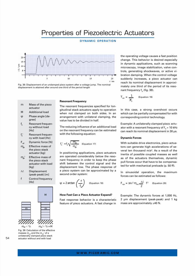
Properties of Piezoelectric ActuatorsdynAMIC OPERAt IOn
Resonant Frequency
The resonant requencies specied or lon-
gitudinal stack actuators apply to operation
when not clamped on both sides In an
arrangement with unilateral clamping, the
value has to be divided in hal
The reducing infuence o an additional load
on the resonant requency can be estimated
with the ollowing equation:
In positioning applications, piezo actuators
are operated considerably below the reso-
nant requency in order to keep the phase
shit between the control signal and the
displacement low The phase response o
a piezo system can be approximated by a
second order system:
How Fast Can a Piezo Actuator Expand?
Fast response behavior is a characteristic
eature o piezo actuators A ast change in
the operating voltage causes a ast position
change This behavior is desired especially
in dynamic applications, such as scanning
microscopy, image stabilization, valve con-
trols, generating shockwaves, or active vi-
bration damping When the control voltage
suddenly increases, a piezo actuator can
reach its nominal displacement in approxi-
mately one third o the period o its reso-
nant requency 0
(g 38)
In this case, a strong overshoot occurs
which can be partially compensated or with
corresponding control technology
Example: A unilaterally clamped piezo actu-
ator with a resonant requency o 0
= 10 kHz
can reach its nominal displacement in 30 µs
Dynamic Forces
With suitable drive electronics, piezo actua-tors can generate high accelerations o se-
veral ten thousand m/s² As a result o the
inertia o possible coupled masses as well
as o the actuators themselves, dynamic
pull orces occur that have to be compensa-
ted or with mechanical preloads (p 50 )
In sinusoidal operation, the maximum
orces can be estimated as ollows:
Example: The dynamic orces at 1,000 Hz,
2 µm displacement (peak-peak) and 1 kg
mass are approximately ±40 N
Tmin ≈ 1 (Equation 19)
3f 0
Fdyn ≈ ±4π2 m
rms
ΔL f 2 (Equation 20)
2
m Mass o the piezo
actuator
M Additional load
φ Phase angle [de-
gree]
f 0
Resonant requen-
cy without load
[Hz]
f 0' Resonant requen-
cy with load [Hz]
Feff
Dynamic orce [N]
meff
Eective mass o
the piezo stack
actuator [kg]
meff ' Eective mass o
the piezo stack
actuator with load
[kg]
ΔL Displacement
(peak-peak) [m]
f Control requency
[Hz]
meff ≈
m/3
M
meff ≈
m/3+M
mm
'
Fig 39: Calculation o the eective
masses me
and the me
' o a
unilaterally clamped piezo stack
actuator without and with load
φ ≈ 2 arctan f
(Equation 18)
f 0
f 0‘ =f 0 m
eff
(Equation 17)
meff ‘√
Fig 38: Displacement o an undamped piezo system ater a voltage jump The nominal
displacement is attained ater around one third o the period length

7/28/2019 Piezoelectric Effect Piezo Techlology Tutorial PI Ceramic
http://slidepdf.com/reader/full/piezoelectric-effect-piezo-techlology-tutorial-pi-ceramic 23/38
5
P I E z O t E Ch nO l O g y
Properties of Piezoelectric ActuatorsElECtR ICAl OPERAt IOn
Operating Voltage
PI Ceramic oers various types o piezo ac-
tuators with dierent layer thicknesses This
results in nominal operating voltages rom
60 V or PICMA® Bender actuators to up to
1000 V or actuators o the PICA series
Electrical Behavior
At operating requencies well below the re-
sonant requency, a piezo actuator behaves
like a capacitor The actuator displacement
is proportional to the stored electrical char-
ge, as a rst order estimate
The capacitance o the actuator depends
on the area and thickness o the ceramic as
well as the material properties In the case
o actuators that are constructed o several
ceramic layers electrically connected in pa-
rallel, the capacitance also depends on the
number o layers
In the actuators there are leakage current
losses in the µA range or below due to the
high internal resistance
Electrical Capacitance Values
The actuator capacitance values indicated
in the technical data tables are small-signal
values, ie measured at 1 V, 1,000 Hz, 20°C,
unloaded The capacitance o piezoceramics
changes with the voltage amplitude, the
temperature and the mechanical load, to
up to 200% o the unloaded, small-signal,
room-temperature value For calculations
under large-signal conditions, it is oten
sucient to add a saety actor o 70% o the
small-signal capacitance (Fig 40)
The small-signal capacitance C o a stack ac-
tuator can be estimated as or a capacitor:
With a xed actuator length l the ollowing
holds true with n ≈ l/hL:
Accordingly, a PICMA® stack actuator with
a layer thickness o 60 µm has an approx
70 times higher capacitance than a PICA
stack actuator with the same volume and
a layer thickness o 500 µm The electric
power consumption P o both types is
roughly the same due to the relationship P ~ C V 2 since the operating voltage changes
proportionally to the layer thickness
Positioning Operation, Static and with Low
Dynamics
When electrically charged, the amount o
energy stored in a piezo actuator is around
E = 1 2 CV 2 Every change in the charge (and
thereore in displacement) is connected
with a charge transport that requires the ol-
lowing current I:
Slow position changes only require a low
current To hold the position, it is only ne-
cessary to compensate or the very low
leakage currents, even in the case o very
high loads The power consumption is cor-
respondingly low
Even when suddenly disconnected rom the
electrical source, the charged actuator will
not make a sudden move The discharge
and thus the return to zero position will hap-
pen continuously and very slowly
Fig 40: Relative change o capacitance o a PICMA®
Stack actuator measured at 1 kHz unipolar sine
signal The electrical capacitance increases along
with the operating voltage and temperature
C Capacitance [C]
n Number o ceramic
layers in the actua-
tor
ε33
T Permittivity =
ε33 / ε
0(c table
p 36) [As/Vm]
A Actuator cross-sec-
tional area [m²]
l Actuator length [m]
h L
Layer thickness in
the actuator [m]
i Current [A]
Q Charge [C, As]
V Voltage on the piezo
actuator [V]
t Time [s]
Fig 41: Structure and contacting o
a stacked piezo translator
33C = n ε T
A
(Equation 21)
h L
33C = l ε T
A
(Equation 22)
h L
2
I =
dQ
= C
dV (Equation 23)
dt dt

7/28/2019 Piezoelectric Effect Piezo Techlology Tutorial PI Ceramic
http://slidepdf.com/reader/full/piezoelectric-effect-piezo-techlology-tutorial-pi-ceramic 24/38
6
w w w . P I C ER A M I C . C O M
Operation with Position Control
In closed-loop operation, the maximum ope-
rating requency is also limited by the phase
and amplitude response o the system Rule
o thumb: The higher the resonant requen-
cy o the mechanical system, the higher the
control bandwidth can be set The sensor
bandwidth and perormance o the cont-
roller (digital or analog, lter and controller
type, bandwidth) also limit the operating
bandwidth o the positioning system
Power Consumption o the Piezo Actuator
In dynamic applications, the power con-
sumption o the actuator increases linearly
with the requency and actuator capaci-
tance A compact piezo translator with a
load capacity o approx 100 N requires less
than 10 watt o reactive power with 1000 Hz
and 10 µm stroke, whereas a high-load
actuator (>10 kN load) requires several
100 watt under the same conditions
Heat Generation in a Piezo Element in
Dynamic OperationSince piezo actuators behave like capacitive
loads, their charge and discharge currents
increase with the operating requency The
thermal active power P generated in the ac-
tuator can be estimated as ollows:
P ≈ π
· tanδ · ƒ · C · V pp
2 (Equation 24)
4
For actuator piezoceramics under small-
signal conditions, the loss actor is on the
order o 001 to 002 This means that up to
2% o the electrical power fowing through
the actuator is converted into heat In the
case o large-signal conditions, this can in-
crease to considerably higher values (Fig
42) Thereore, the maximum operating re-
quency also depends on the permissible
operating temperature At high requencies
and voltage amplitudes, cooling measures
may be necessary For these applications,PI Ceramic also oers piezo actuators with
integrated temperature sensors to monitor
the ceramic temperature
Continuous Dynamic Operation
To be able to operate a piezo actuator at the
desired dynamics, the piezo amplier must
meet certain minimal requirements To
asses these requirements, the relationship
between amplier output current, operating
voltage o the piezo actuator, and operating
requency has to be considered
Driving with Sine Functions
The eective or average current Ia
o the
amplier specied in the data sheets is the
crucial parameter or continuous operation
with a sine wave Under the dened ambi-
ent conditions, the average current values
are guaranteed without a time limit
I a
≈ ƒ · C · V pp
(Equation 25)
Equation 26 can be used or sinusoidal
single pulses that are delivered or a short
time only The equation yields the requiredpeak current or a hal-wave The amplier
must be capable o delivering this peak cur-
rent at least or hal o a period For repeated
single pulses, the time average o the peak
currents must not exceed the permitted
average current
I max
≈ ƒ · π · C · V pp
(Equation 26)2,51,5 2,00,5 1,00,0
0,30
0,25
0,10
0,15
0,20
0,05
0,00
EPP [kV/mm]
t a n δ
PIC255 shear bipolar
PIC255 longitudinal bipolar
PIC151 longitudinal unipolar
PIC252/255 longitudinal unipolar
Fig 42: Dielectric loss actors tan δ
or dierent materials and control
modes at room temperature andwith quasistatic control The
conversion between voltage and
eld strength or specic actuators
is done with the layer thicknesses
that are given starting on p 42
The actual loss actor in the com-
ponent depends on urther actors
such as the mechanical preload,
the temperature, the control re-
quency, and the amount o passive
material
The average current, peak
current and small-signal
bandwidth or each piezo
amplier rom PI can be
ound in the technical
data
P Power that is conver-
ted into heat [W]
tan δ Dielectric loss actor
(ratio o active power
to reactive power)
f Operating requency
[Hz]
C Actuator capacitance
[F]
V pp
Driving voltage
(peak-to-peak) [V]
Electrical Operation (continued)

7/28/2019 Piezoelectric Effect Piezo Techlology Tutorial PI Ceramic
http://slidepdf.com/reader/full/piezoelectric-effect-piezo-techlology-tutorial-pi-ceramic 25/38
5
P I E z O t E Ch nO l O g y
Driving with Triangular Waveorm
Both the average current and the peak cur-
rent o the amplier are relevant or driving
a piezo actuator with a symmetrical trian-
gular waveorm The maximum operating
requency o an amplier can be estimated
as ollows:
f max
≈ 1
·
I a (Equation 27)
C V pp
A secondary constraint that applies here is
that the amplier must be capable o de-
livering at least Imax
= 2 Ia
or the charging
time, ie or hal o the period I this is not
easible, an appropriately lower maximum
operating requency should be selected For
ampliers which cannot deliver a higher
peak current or not or a sucient period o
time, the ollowing equation should be used
or calculation instead:
f max
≈
1
·
I a (Equation 28)
2 · C V pp
Signal Shape and Bandwidth
In addition to estimating the power o the
piezo amplier, assessing the small-sig-
nal bandwidth is important with all signal
shapes that deviate rom the sinusoidal
shape
The less the harmonics o the control sig-
nal are transerred, the more the resulting
shape returns to the shape o the dominant
wave, ie, the sinusoidal shape The band-
width should thereore be at least ten-old
higher than the basic requency in order to
prevent signal bias resulting rom the non-
transerred harmonics
In practice, the limit o usable requency
portions to which the mechanical piezo
system can respond is the mechanical reso-
nant requency For this reason, the electri-
cal control signal does not need to include
clearly higher requency portions
Switching Applications, Pulse-mode
Operation
The astest displacement o a piezo ac-
tuator can occur in 1/3 o the period o its
resonant requency (p 54) Response times
in the microsecond range and accelerations
o more than 10,000 g are easible, but
require particularly high peak current rom
the piezo amplier
This makes ast switching applications such
as injection valves, hydraulic valves, swit-ching relays, optical switches, and adaptive
optics possible
For charging processes with constant cur-
rent, the minimal rise time in pulse-mode
operation can be determined using the ol-
lowing equation:
t ≈ C ·
V pp (Equation 29)
I max
As beore, the small-signal bandwidth o the
amplier is crucial The rise time o the am-plier must be clearly shorter than the piezo
response time in order not to have the amp-
lier limit the displacement In practice, as a
rule-o-thumb, the bandwidth o the ampli-
er should be two- to three-old larger than
the resonance requency
Advantages and Disadvantages o Position
Control
A position control-loop always operates in
the linear control portion o voltages and
currents Since the peak current is limited in
time and is thereore nonlinear, it cannot be
used or a stable selection o control para-
meters As a result, position control limits
the bandwidth and does not allow or pulse-
mode operation as described
In switching applications, it is thereore
oten not possible to attain the necessary
positional stability and linearity by position
control Linearization can be attained eg
by means o charge-controlled ampliers
(p 63) or by numerical correction methods
Ia
average current
o the amplier
(source / sink) [A]
Imax
peak current o the
amplier (source /
sink) [A]
f operating requency
[Hz]
f max
maximum operating
requency [Hz]
C actuator capaci-
tance, large signal
[Farad (As/V)]
Vpp
driving voltage
(peak-to-peak) [V]
t time to charge piezo
actuator to Vpp
[s]
The average current and
peak current or each pi-
ezo amplier rom PI can
be ound in the technical
data
Fig 43: PICMA® actuators with pa-tented, meander-shaped external
electrodes or up to 20 A charging
current

7/28/2019 Piezoelectric Effect Piezo Techlology Tutorial PI Ceramic
http://slidepdf.com/reader/full/piezoelectric-effect-piezo-techlology-tutorial-pi-ceramic 26/38
8
w w w . P I C ER A M I C . C O M
Properties of Piezoelectric Actuators AMb I Ent COnd I t I Ons
Piezo actuators are suitable or operation in
very dierent, sometimes extreme ambient
conditions Inormation on use at high tem-
peratures o up to 200°C as well as in cryoge-
nic environments is ound starting on p 48
Vacuum Environment
Dielectric Stability
According to Paschen's Law, the breakdown
voltage o a gas depends on the product o
the pressure p and the electrode gap s Air
has very good insulation values at atmos-
pheric pressure and at very low pressures
The minimum breakdown voltage o 300 V
is at a ps product o 1000 Pa mm PICMA®
Stack with nominal voltages o considerably
less than 300 V can thereore be operated at
any intermediate pressure In order to pre-
vent breakdowns, PICA piezo actuators with
nominal voltages o more than 300 V, howe-
ver, should not be operated or only be driven
at strongly reduced voltages when air is in
the pressure range o 100 to 50000 Pa
Outgassing
The outgassing behavior depends on the
design and construction o the piezo actua-
tors PICMA® actuators are excellently suited
to use in ultrahigh vacuums, since they are
manuactured without polymer components
and can be baked out at up to 150°C UHV
options with minimum outgassing rates are
also oered or dierent PICA actuators
Inert Gases
Piezo actuators are suitable or use in inert
gases such as helium, argon, or neon Howe-
ver, the pressure-dependent fashover resis-tances o the Paschen curves must also be
observed here as well The ceramic-insulated
PICMA® actuators are recommended or this
use, since their nominal voltage is below the
minimum breakdown voltages o all inert ga-
ses For PICA actuators with higher nominal
voltages, the operating voltage should be
decreased in particular pressure ranges to
reduce the fashover risk
Magnetic Fields
Piezo actuators are excellently suited to be
used in very high magnetic elds, eg, at
cryogenic temperatures as well PICMA®
actuators are manuactured completely
without erromagnetic materials PICA stack
actuators are optionally available without
erromagnetic components Residual mag-
netisms in the range o a ew nanotesla have
been measured or these products
Gamma Radiation
PICMA® actuators can also be operated in
high-energy, short-wave radiation, which oc-
curs, or example, with electron accelerators
In long-term tests, problem-ree use with
total doses o 2 megagray has been proven
Environments with High Humidity
When piezo actuators are operated in dry
environments, their lietime is always
higher than in high humidity When the
actuators are operated with high-requency
alternating voltages, they sel-heat, thus kee-
ping the local moisture very low
Continuous operation at high DC-voltages in
a damp environment can damage piezo actu-
ators (p 59) This especially holds true or the
actuators o the PICA series, since their active
electrodes are only protected by a polymer
coating that can be penetrated by humidity
The actuators o the PICMA® series have an
all-ceramic insulation, which considerab-
ly improves their lietime in damp ambient
conditions compared to polymer-coated
actuators (p 59)
Liquids
Encapsulated PICMA® or specially encased
PICA actuators are available or use in
liquids For all other actuator types, direct
contact with liquids should be avoided
Highly insulating liquids can be exceptions to
this rule Normally, however, the compatibili-
ty o the actuators with these liquids must be
checked in lietime tests
In case o questions regar-
ding use in special envi-
ronments, please contact
ino@piceramiccom

7/28/2019 Piezoelectric Effect Piezo Techlology Tutorial PI Ceramic
http://slidepdf.com/reader/full/piezoelectric-effect-piezo-techlology-tutorial-pi-ceramic 27/38
5
P I E z O t E Ch nO l O g y
Lietime when Exposed to DC-Voltage
In nanopositioning applications, constant
voltages are usually applied to the piezo
actuator or extended periods o time In
the DC operating mode, the lietime is in-
fuenced mainly by atmospheric humidity
I the humidity and voltage values are very
high, chemical reactions can occur and
release hydrogen molecules which then de-
stroy the ceramic composite by embrittling
it
All-Ceramic Protective Layer
The patented PICMA® design suppresses
these reactions eectively In contrast to
coating made just o polymer, the inorga-
nic ceramic protective layer (p 42) prevents
the internal electrodes rom being exposed
to water molecules and thus increases the
lietime by several orders o magnitude (g
43)
Quasi-static Conditions: Accelerated Lie-
time Test
Due to their high reliability, it is virtually
impossible to experimentally determine
the lietime o PICMA® actuators under real
application conditions Thereore, tests un-
der extreme load conditions are used to
estimate the lietime: Elevated atmospheric
humidity and simultaneously high ambient
temperatures and control voltages
Fig 44 shows the results o a test that was
conducted at a much increased atmospheric
humidity o 90% RH at 100 V DC and 22°C
The extrapolated mean lietime (MTTF,
mean time to ailure) o PICMA® actuatorsamounts to more than 400,000 h (approx
47 years) while comparative actuators with
polymer coating have an MTTF o only
approx one month under these conditions
Tests under near-realistic conditions con-
rm or even surpass these results
Calculation o the Lietime when Exposed
to DC-Voltage
Elaborate investigations have been done
to develop a model or calculation o the
lietime o PICMA® Stack actuators The ol-
lowing actors need to be taken into account
under actual application conditions: Ambi-
ent temperature, relative atmospheric humi-
dity, and applied voltage
The simple ormula
MTTF = AU
· AT
· AF (Equation 30)
allows the quick estimation o the average
lietime in hours The actors AU
as a unc-
tion o the operating voltage, AT
or the am-
bient temperature and AF
or the relative
atmospheric humidity can be read rom the
diagram (g 45)
REl IAb I l I ty OF P ICMA ® Mult I lAyER ACtuAtORs
Properties of Piezoelectric Actuators
Fig 44: Results o an accelerated lietime test with increased humidity (test conditions:
PICMA® Stack and polymer-coated actuators, dimensions: 5 x 5 x 18 mm³, 100 V DC, 22 °C,
90% RH)
Important: Decreasing
voltage values are asso-ciated with exponential
increases o the lietime
The expected lietime at
80 V DC, or example, is
10 times higher than at
100 V DC
This calculation can also
be used to optimize a
new application with
regard to lietime as
early as in the design
phase A decrease in
the driving voltage orcontrol o tempera-
ture and atmospheric
humidity by protective
air or encapsulation o
the actuator can be very
important in this regard

7/28/2019 Piezoelectric Effect Piezo Techlology Tutorial PI Ceramic
http://slidepdf.com/reader/full/piezoelectric-effect-piezo-techlology-tutorial-pi-ceramic 28/38
0
w w w . P I C ER A M I C . C O M
Lietime in Dynamic Continuous Operation
Cyclic loads with a rapidly alternating elec-
trical eld and high control voltages (typi-
cally > 50 Hz; > 50 V) are common conditions
or applications such as valves or pumps
Piezo actuators can reach extremely high
cycles-to-ailure under these conditions
The most important actors aecting the
lietime o piezo actuators in this context are
the electrical voltage and the shape o the
signal The impact o the humidity, on the
other hand, is negligible because it is redu-
ced locally by the warming-up o the piezo
ceramic
Ready or Industrial Application: 10 10
Operating Cycles
Tests with very high control requencies de-
monstrate the robustness o PICMA® piezo
actuators Preloaded PICMA® actuators with
dimensions o 5 x 5 x 36 mm were loaded at
room temperature and compressed air coo-ling with a sinusoidal signal o 120 V unipo-
lar voltage at 1,157 Hz, which corresponds
to 108 cycles daily Even ater more than 1010
cycles, there was not a single ailure and the
actuators showed no signicant changes in
displacement
Patented Design Reduces the Mechanical
Stress
PICMA® actuators utilize a special paten-
ted design Slots on the sides eectively
prevent excessive increases o mechanical
tensile stresses in the passive regions o
the stack and the ormation o un-controlled
cracks (g 46) that may lead to electrical
breakdowns and thus damage to the actu-
ator Furthermore, the patented meander-
shaped design o the external contact strips
(g 43) ensures all internal electrodes have
a stable electrical contact even at extreme
dynamic loads
Reliability of PICMA® Multilayer Actuators (Continued)
Fig 46: The patented PICMA®
actuator design with its dened
slots preventing uncontrolled
cracking due to stretching upon
dynamic control is clearly visible
Fig 45: Diagram or calculati-
on o the lietime o PICMA®
stack actuators when exposed
to DC-voltage For continuous
operation at 100 V DC and 75%
relative humidity (RH) and an
ambient temperature o 45°C,
the ollowing values can be
read rom the diagram: AF=14
(humidity, blue curve), AT=100
(temperature, red curve), and
AU=75 (operating voltage,
black curve) The product
results in a mean lietime o
105,000 h, more than 11 years

7/28/2019 Piezoelectric Effect Piezo Techlology Tutorial PI Ceramic
http://slidepdf.com/reader/full/piezoelectric-effect-piezo-techlology-tutorial-pi-ceramic 29/38
6
P I E z O t E Ch nO l O g y
Piezo Electronics for Operating Piezo ActuatorsChARACtER Ist IC bEhAV IOR OF P I EzO AMPl I F I ERs
Fast settling or slow speed with high con-
stancy, high positional stability, high resolution
and high dynamics – the requirements placed
on piezo systems vary greatly and need a
control with a high degree o fexibility
The control electronics play a key role in the
perormance o piezoelectric actuators and
nanopositioning systems Ultra-low-noise,
high-stability linear ampliers are essential
or precise positioning, because piezo actua-
tors respond to the smallest changes in the
control voltage with a displacement Noise
or driting must be avoided as much as pos-
sible The prerequisite or the high-dynamics
displacement o the actuator is or the voltage
source to provide sucient current to charge
the capacitance
Power Requirements or Piezo Operation
The operating limit o an amplier with a
given piezo actuator depends on the amplier
power, the amplier design and the capaci-
tance o the piezo ceramics (c p 56–57) In
high-dynamics applications, piezo actuators
require high charge and discharge currentsThe peak current is o special importance,
particularly or sinusoidal operation or pulse
operation Piezo ampliers rom PI are there-
ore designed so that they can output and sink
high peak currents I an amplier is operated
with a capacitive load and requency at which
it can no longer produce the required current,
the output signal will be distorted As a
result, the ull displacement can no longer be
attained
Amplifer Frequency Response Curve
The operating limits o each amplier modelare measured with dierent piezo loads de-
pending on the requency and output volta-
ge and are graphically displayed as amplier
response curves to make the selection easier
The measurements are perormed ater 15
minutes o continuous operation (piezo and
amplier) at room temperature In cold condi-
tion ater power up, more power can be brie-
ly available
The power amplier operates linearly within
its operating limits so that the control signal
is amplied without distortion In particular,
no thermal limitation takes place, ie the am-
plier does not overheat, which could cause
distortions o the sine wave The amplier
continuously provides the output voltage
even over a long time This amplier respon-
se curve cannot be used or peak values that
are only available or a short period
The curves reer to open-loop operation; in
closed-loop operation, other actors limit the
dynamics
Setting the Operating Voltage
Ater the operating limit o the amplier has
been reached, the amplitude o the opera-
ting voltage must be reduced by the same
proportion as the output voltage alls, i the
requencies continue to increase This is
important because the current require-
ment continuously increases along with the
requency Otherwise, the output signal will
be distorted
Example: The E-503 (E-663) amplier can
operate a 23 µF piezo capacitance with
an output voltage o 100 V and a maximum
requency o approximately 15 Hz (with sine
wave excitation) At higher requencies the
operating limit decreases, e g to 80 V at
20 Hz In order to obtain a distortion-ree
output signal at this requency, the control
input voltage must be reduced to 8 V (voltage
gain = 10)
Fig 47: Amplier requency
response curve, determined with
dierent piezo loads, capacitance
values in µF Control signal sine,
operation period > 15 min, 20° C
Here: E-617, a switched amplier
with energy recovery

7/28/2019 Piezoelectric Effect Piezo Techlology Tutorial PI Ceramic
http://slidepdf.com/reader/full/piezoelectric-effect-piezo-techlology-tutorial-pi-ceramic 30/38
2
w w w . P I C ER A M I C . C O M
Piezo Electronics for Operating Piezo ActuatorssOlut IOns FOR h Igh -dynAMICs 24/7 OPERAt IOn
Switching Amplifers with Energy
Recovery
Piezo actuators are oten used or an es-
pecially precise materials processing, or
example in mechanical engineering or ne
positioning in milling and turning machines
These require high orces as well as dyna-
mics The piezo actuators are correspon-
dingly dimensioned or high orces; ie
piezo actuators with a high capacitance are
used here Particularly high currents are
required to charge and discharge them with
the necessary dynamics The control o
valves also requires similar properties
Energy Recovery Minimizes the Energy
Consumption in Continuous Operation
Since these applications requently run
around the clock, seven days a week, the
energy consumption o the amplier is
particularly important For this purpose,
PI oers switching amplier electronics
with which the pulse width o the control
signal is modulated (PWM) and the piezo
voltage is thereby controlled This resultsin an especially high eciency In addition,
a patented circuitry or energy recovery is
integrated: this stores part o the returning
energy in a capacitive store when a piezo is
discharged and makes the energy available
again or the next charging operation This
permits energy savings o up to 80% to be
realized Furthermore, the amplier does
not heat up so much and thus infuences the
actual application less
Unlike conventional class D switching
ampliers, PI switching ampliers or
piezo elements are current- and voltage-
controlled Product examples are the E-617or PICMA® actuators (p 29) and E-481 or
the PICA actuator series (p 31)
Protection o the Piezo Actuator through
Overtemperature Protection
In continuous operation, the heat develop-
ment in the piezo actuator is not negligible
(p 56) Corresponding electronics can there-
ore evaluate the signals o a temperature
sensor on the piezo This protects the cera-
mic rom overheating and depolarization
Valid patents
German patent no 19825210C2International patent no 1080502B1
US patent no 6617754B1
Fig 48: Piezo actuator in a case
with connections or temperature
sensor and cooling air
0
20
40
60
80
100
0 20 40 60 80 100
E f f i c i e n c y i n %
Output power, relative to max. in %
Switching amplifier Linear amplifier
0,00
5,00
10,00
15,00
20,00
25,00
0 500 1000 1500 2000
P o w e r c o n s u m
p t i o n i n W
Frequency in Hz
Linear amplifier
Switching amplif ier
Fig 49: Thanks to their patented energy recovery system, PI
ampliers only consume approx 20% o the power required
by a corresponding linear amplier with the same output
power
Fig 50: Power consumption o a piezo amplier with linear and
switching amplier at the piezo output, capacitive load 1 µF The
measured values clearly show that the pulse width modulated amplier
allows signicantly higher dynamics than the classic linear amplier
The linear amplier reaches the upper limit o its power consumption
at requencies o up to approx 700 Hz, the switching amplier does not
reach the limit until ar beyond 2 kHz
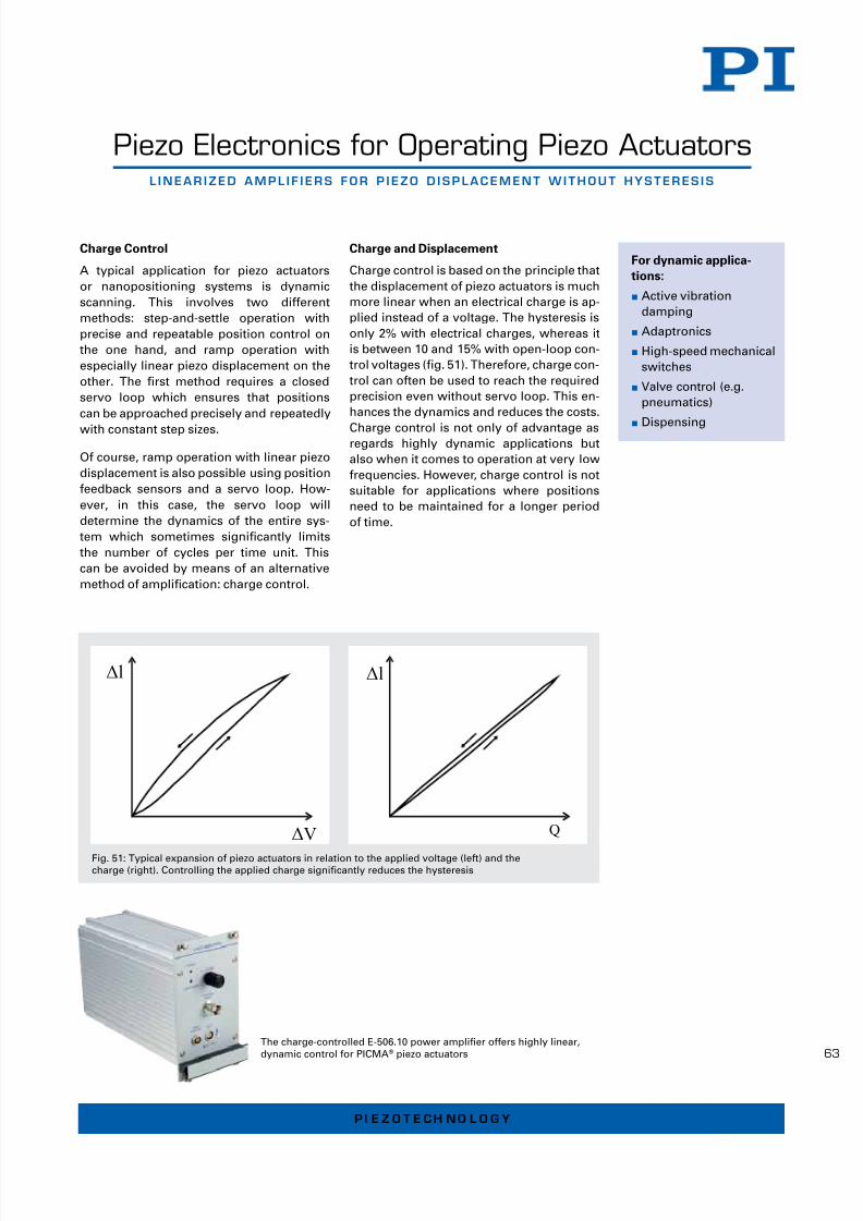
7/28/2019 Piezoelectric Effect Piezo Techlology Tutorial PI Ceramic
http://slidepdf.com/reader/full/piezoelectric-effect-piezo-techlology-tutorial-pi-ceramic 31/38
6
P I E z O t E Ch nO l O g y
Piezo Electronics for Operating Piezo Actuatorsl InEAR IzEd AMPl I F I ERs FOR P I EzO d IsPlACEMEnt wIthOut hystEREs Is
Charge Control
A typical application or piezo actuators
or nanopositioning systems is dynamic
scanning This involves two dierent
methods: step-and-settle operation with
precise and repeatable position control on
the one hand, and ramp operation with
especially linear piezo displacement on the
other The rst method requires a closed
servo loop which ensures that positions
can be approached precisely and repeatedly
with constant step sizes
O course, ramp operation with linear piezo
displacement is also possible using position
eedback sensors and a servo loop How-
ever, in this case, the servo loop will
determine the dynamics o the entire sys-
tem which sometimes signicantly limits
the number o cycles per time unit This
can be avoided by means o an alternative
method o amplication: charge control
Charge and Displacement
Charge control is based on the principle that
the displacement o piezo actuators is much
more linear when an electrical charge is ap-
plied instead o a voltage The hysteresis is
only 2% with electrical charges, whereas it
is between 10 and 15% with open-loop con-
trol voltages (g 51) Thereore, charge con-
trol can oten be used to reach the required
precision even without servo loop This en-
hances the dynamics and reduces the costs
Charge control is not only o advantage asregards highly dynamic applications but
also when it comes to operation at very low
requencies However, charge control is not
suitable or applications where positions
need to be maintained or a longer period
o time
Fig 51: Typical expansion o piezo actuators in relation to the applied voltage (let) and the
charge (right) Controlling the applied charge signicantly reduces the hysteresis
ΔV
Δl
Q
Δl
For dynamic applica-
tions:
Active vibration
damping
Adaptronics
High-speed mechanical
switches
Valve control (eg
pneumatics)
Dispensing
The charge-controlled E-50610 power amplier oers highly linear,
dynamic control or PICMA® piezo actuators

7/28/2019 Piezoelectric Effect Piezo Techlology Tutorial PI Ceramic
http://slidepdf.com/reader/full/piezoelectric-effect-piezo-techlology-tutorial-pi-ceramic 32/38
4
w w w . P I C ER A M I C . C O M
Handling
Piezo actuators are subject to high mechani-
cal and electrical loads Moreover, the brittle
ceramic or crystalline materials require
careul handling
Avoid mechanical shocks to the actuator,
which can occur during alls, or example
Do not use metal tools during installation
Avoid scratching the ceramic or polymer
coating and the end suraces during ins-
tallation and use
Prevent the ceramic or polymer insulation
rom coming into contact with conductive
liquids (such as sweat) as well as metal
dust
I the actuator is operated in a vacuum:
Observe the inormation on the per-
missible piezo voltages in particular pres-
sure ranges (p 58)
I the actuator can come into contact with
insulating liquids such as silicone or hyd-
raulic oils, contact ino@piceramicde
I the actuator has accidently become dir-
ty, careully clean the actuator with isop-
ropanol or ethanol beore putting it back
into operation Next, completely dry it in
a drying cabinet Never use acetone or
cleaning When cleaning in an ultrasonic
bath, reduce the energy input to the ne-
cessary minimum
Recommendation: Wear gloves and
protective glasses during installation and
start-up
DuraAct patch actuators and encapsulated
PICMA® piezo actuators have a particularly
robust construction They are partially
exempt rom this general handling inorma-
tion
Mechanical Installation (g 52, 53, 54)
Avoid torques and lateral orces whenmounting and operating the actuator by
using suitable structures or guides
When the actuator is operated dynami-
cally: Install the actuator so that the center
o mass o the moving system coincides
with the actuator axis, and use a guiding
or very large masses
Establish contact over as large an area as
possible on the end suraces o a stack
actuator
Select opposing suraces with an even-
ness o only a ew micrometers
Gluing
I the mounting surace is not even, use
epoxy resin adhesives or gluing the
actuator Cold-curing, two-component
adhesives are well suited or reducing
thermo-mechanical stresses
Maintain the operating temperature
range specied or the actuator during
hardening and observe the temperature
expansion coecients o the involved
materials
Uneven mounting suraces are ound, or
example, with PICMA® Bender and PICMA®
Chip actuators, since these suraces are not
re-ground ater sintering (g 55)
. . :
. . :. . :
Fig 52: Avoiding lateral orces and
torques
Fig 54: Avoiding tensile stresses
by means o a mechanical preload
Fig 55: Mounting by gluing o a one-sidedly
clamped bending actuator
Fig 53: Prevention o torques
OF P I EzO ACtuAtORs

7/28/2019 Piezoelectric Effect Piezo Techlology Tutorial PI Ceramic
http://slidepdf.com/reader/full/piezoelectric-effect-piezo-techlology-tutorial-pi-ceramic 33/38
6
P I E z O t E Ch nO l O g y
Applying a Preload (fg. 54)
Create the preload either externally in
the mechanical structure or internally in
a case
Apply the preload near the axis within the
core cross-section o the actuator
I the actuator is dynamically operated and
the preload is created with a spring: Use
a spring whose total stiness is approxi-
mately one order o magnitude less than
that o the actuator
Introducing the Load Evenly (fg. 56)
The parallelism tolerances o the mecha-
nical system and the actuator result in an
irregular load distribution Thereore, com-
pressive stresses may cause tensile stresses
in the actuator As regards the even appli-
cation o the load, there are dierent de-
sign solutions that dier rom each other in
terms o the axial stiness, the separability
o the connection as well as the rotatability
in operation, eg in the case o lever ampli-
cation Gluing the actuator (p 64, Gluing section)
Hardened spherical end piece with point
contact to even opposing surace
Hardened spherical end piece with ring
contact to a spherical cap
Connection via a fexure joint
I the actuator is coupled in a milling po-
cket, make sure that there is ull-area con-
tact on the end surace o the actuator For
this purpose, select the dimensions o the
milling pocket correspondingly or make
ree cuts in the milling pocket (Fig 57)
I a point load is applied to the end piece
o the actuator: Dimension the end piece
so that its thickness corresponds to hal
the cross-sectional dimension in order to
prevent tensile stresses on the actuator
(g 58)
Electrical Connection (g 59)
From an electrical point o view, piezo
actuators are capacitors that can store a
great amount o energy Their high internal
resistances lead to very slow discharges
with time constants in the range o hoursMechanical or thermal loads electrically
charge the actuator
Connect the case or the surrounding me-
chanics to a protective earth conductor in
accordance with the standards
Electrically insulate the actuator against
the peripheral mechanics At the same
time, observe the legal regulations or the
respective application
Observe the polarity o the actuator du-
ring connection
Only mount the actuator when it is short-
circuited
When the actuator has charged: Dis-
charge the actuator in a controlled
manner with a 10 kΩ resistance Avoid
directly short-circuiting the terminals o
the actuator
Do not pull out the connecting cable to
the amplier when voltage is present
The mechanical impulse triggered by this
could damage the actuator
Sae Operation
Reduce the DC voltage as much as
possible during operation o the actuator
(p 59) You can decrease oset voltages
with semibipolar operation
Always switch o the actuator when it is
not needed
Avoid steep edges in the piezo voltage,
since they can trigger strong dynamic
orces when the actuator does not have
a preload Steep edges can occur, or
example, when digital wave generators
are switched on
Tensile
stresses
Tensile
stresses
Fig 56: Avoiding an irregular load application
Fig 57: Full-area contact o the
actuator
Fig 58: Proper dimensioning o
the end pieces in the case o point
contact
Fig 59: Mechanical loads electri-
cally charge the actuator Moun-
ting only when short-circuited

7/28/2019 Piezoelectric Effect Piezo Techlology Tutorial PI Ceramic
http://slidepdf.com/reader/full/piezoelectric-effect-piezo-techlology-tutorial-pi-ceramic 34/38
6
w w w . P I C ER A M I C . C O M
PI (Physik Instrumente) is the leading supplier
o piezo-based positioning systems with accu-
racies in the range o a ew nanometers.
The extensive product portfolio is based on a
wide range of technologies with electromotive
or piezoelectric drives for up to six motion axes.
Hexapods, nanometer sensors, control electro-
nics as well as software and are supplemented
by customized solutions.
All key technologies are developed in-house.
This means that every phase from the design
right down to the shipment can be controlled:
The precision mechanics and the electronics as
well as the position sensors and the piezo cera-
mics or actuators. The latter are produced by
the subsidiary company PI Ceramic.
PI is, therefore, the only manufacturer of nano-
positioning technology which employs the
piezoelectric drives it produces. This ensures a
high degree of flexibility for developing custo-
mized piezoceramic components.
More than 100 patents and patents applied for
stand for more than 40 years of experience and
pioneering work. PI products are employed
wherever technology in industry and research
is pushed forward – worldwide.
With four German factories and ten subsidiaries
and sales offices abroad, the PI group is repre-
sented internationally.
PI stands for quality in products, processes and
service. The ISO-9001 certification, which focu-
ses not only on product quality but also on
customer expectations and satisfaction, was
achieved back in 1994.
PI is also certified according to the ISO 14001
(environmental management) and OHSAS
18001 (occupational safety) standards, which
taken together form an Integrated Manage-
ment System (IMS).
Future Technology
Solutions
Today PI delivers micro-
and nanopositioning solu-
tions or all important
high-tech markets:
n Semiconductor technology
n Optical metrology,
microscopy
n Biotechnology and
medical devices
n Precision automation
and handling
n Precision machining
n Data storage technology
n Photonics, tele-
communications
n Nanotechnology
n Micropositioning
n Aviation and aerospace
n Astronomy
FOR IndustRy And REsEARCh
Drives that Set the World in Motion

7/28/2019 Piezoelectric Effect Piezo Techlology Tutorial PI Ceramic
http://slidepdf.com/reader/full/piezoelectric-effect-piezo-techlology-tutorial-pi-ceramic 35/38P I E z O t E Ch nO l O g y
1970 PI founding year
1977 PI headquarters move to Waldbronn,
Germany
1987 Foundation of a subsidiary in the USA
1991 Foundation of a subsidiary in Japan
1991 Market launch of 6-axis parallel-
kinematics positioning systems
(Hexapods)
1992 Foundation of PI Ceramic, Thuringia,
Germany; crucial step towards market
leadership in nanopositioning
1993 Foundation of subsidiaries in the UK
and in France
1994 Market launch of capacitive position
sensors
1995 Foundation of a subsidiary in Italy
1998 Market launch of digital control
electronics
2001 Market launch of PILine® Ultrasonic
Piezomotors
2001 New company building in Karlsruhe,
Germany
2002 PI Ceramic company building extended
2002 Foundation of a subsidiary in China
2002 Market launch of PICMA® multilayer
Piezo stack actuators
2004 Market launch of NEXLINE® high-
performance piezo linear drives
2007 Market launch of NEXACT® piezo
linear drives
2010 Acquisition of the expansion site next
to the PI headquarters
2011 Foundation of a subsidiary in Korea
2011 Foundation of a subsidiary in Singapore
2011 Acquisition of the majority shares of
miCos GmbH
2012 Extension of the buildings in Karlsruhe
and Lederhose
A s u C C E s s s t O R y
Milestones
6

7/28/2019 Piezoelectric Effect Piezo Techlology Tutorial PI Ceramic
http://slidepdf.com/reader/full/piezoelectric-effect-piezo-techlology-tutorial-pi-ceramic 36/38
8
w w w . P I C ER A M I C . C O M
I I I II I I I
I I I II I I I
I I I II I I I
nAnOPOsIt IOnIng systEMs, MICROPOsIt IOnIng
tEChnOlOgy & nAnOMEtROlOgy
Product Portfolio
Nanopositioning
Resolution Down to Picometers
Nanopositioning systems achieve motion resolu-tions and positioning accuracy in the nanometerrange and below The target position is achievedwithin a ew milliseconds and stably maintainedPiezo actuators or piezo stepping drives are usedas drives Digital motion controllers optimize theperormance o the system These systems arerequired in optical metrology, microscopy, or inmicrochip production To achieve the necessaryposition resolution and stability, PI manuacturesand develops the sensor systems and oers theseas an independent product line
From linear axes to motion in 6
degrees o reedom
Parallel-kinematic principle or multi-
axis systems
Versions with direct position mea-
surement
– capacitive sensors:
Subnanometer resolution
– Incremental sensors: Nanometer
resolution, wide measurement
ranges
Available in a variety o designs,
travel ranges, and precision classes
PiezoWalk® Stepping Drives
Precise Positioning over Several Millimeters
Piezo stepping drives transer the advantages o conventional piezo actuators to applications withlarger travel ranges The interplay o the motion
o individual actuators brings about a walk mo-tion with high resolution and dynamics within asingle step and thus, in principle, allows unlimi-ted travel ranges The actuators are prestressedagainst the moving slider The drive is thereoresel-locking when switched o without holdingcurrents or additional mechanical componentsThere is thereore no heat dissipation or controldither, the position is maintained with a high de-gree o stability
Two principles:
– NEXLINE®: Generated orce up to
600 N
– NEXACT®: Fast motion and gene-
rated orce up to 10 N
Integration levels rom an economi-
cal OEM drive to a multi-axis positio-
ning system
Compact design, variable travel due
to variable rod length
Nanometer resolution
Vacuum compatible and non-
magnetic
PILine® Ultrasonic Piezomotors
Small and Fast over Long Distances
Ultrasonic piezomotors are an alternative to theconventional motor spindle combinations or tomagnetic drives and allow outstandingly fat po-sitioning systems They oer excellent start/stopdynamics, high velocity and sel-locking in a smallpackage PI supplies miniaturized versions, OEMmotors and drives, and also complete positioningsystems with controller Piezomotors rom PI arevacuum-compatible in principle and suitable oroperation under strong magnetic elds
Integration levels rom an economi-
cal OEM drive to a multi-axis positio-
ning system Flexible travel ranges
Easy mechanical integration
Sel-locking at rest
Holding orce to 15 N
Velocity to 500 mm/s

7/28/2019 Piezoelectric Effect Piezo Techlology Tutorial PI Ceramic
http://slidepdf.com/reader/full/piezoelectric-effect-piezo-techlology-tutorial-pi-ceramic 37/38
6
P I E z O t E Ch nO l O g y
Hexapods - Parallel-Kinematic Positioning
Systems
High-Precision Motion Control in up to Six Axes
PI uses parallel-kinematic designs wherever mul-ti-axis and high-precision motion is required Alldrives act directly on the same moving platormThis creates advantages in the precision anddynamics compared to stacked axes, where theerrors o the individual axes are cumulative anddynamic losses are caused because the upperaxes are also carried along The parallel-kinema-tic principle is independent o the drive used Itis thus possible to produce micropositioning andnanopositioning systems with motion in up to sixdegrees o reedom
Low moving mass, low inertia
Excellent dynamic behavior, ast
step-and-settle
Small installation space
High stiness
Freely denable pivot point
Minimized axis crosstalk motion
Very good repeatability
For all drive systems
High resolution D/A and A/D con-
verters, state o the art processor
technology
Digital real-time interaces
Extensive sotware and drivers
Inormation on coordinates or
parallel kinematics/Hexapods
Digital Control Technology
Achieve the Optimum in Perormance
The perormance characteristics o a precisionpositioning system depend equally on the stagemechanics and the control Digital controllers use
specially adapted algorithms to process processvalues such as sensor signal or position target va-lue Motions on trajectories, settling times, or tra-jectory deviations can thus be optimized duringast scanning operations
Linear positioners
– Travel ranges between 5 and
1000 mm– Velocity to 150 mm/s
– Low-cost designs, variants as
modular system
DC and stepper micrometer drives
– Travel ranges to 50 mm and veloci-
ty to 30 mm/s
– Resolution to <100 nm
Rotary stage with unlimited slewing
range
– to 720 °/s
– Resolution to 1 µrad
– ncremental encoders or direct po-
sition measurement as an optional
extra
Micropositioning
Precision Positioning over Long Travel
Micropositioning systems provide motion reso-lution and positioning accuracies in the rangebetween a ew tens o micrometers and 01 µmBrushless DC or stepper motors are available asdrives, as well as linear drives such as PILine® ul-trasonic piezomotors or NEXACT® piezo steppingdrives The precision o the system depends onthe integrated drive, position sensor, and guidesIn conventional motors, the quality o the gear,the spindle, or the worm drive play also an essen-tial role Digital controls with suitable control andlinearization methods make it possible to improvethe system characteristics

7/28/2019 Piezoelectric Effect Piezo Techlology Tutorial PI Ceramic
http://slidepdf.com/reader/full/piezoelectric-effect-piezo-techlology-tutorial-pi-ceramic 38/38
P I E Z O N A N O P O S I T I O N I N G
JAPAN
PI Japan Co., Ltd.TachikawaBusiness Center Bldg. 5F2-38-5 Akebono-choTachikawa-shi, Tokyo 190-0012Tel. +81 (42) 526 7300Fax +81 (42) 526 [email protected]
PI Japan Co., Ltd.Hanahara Daini Bldg. #7034-11-27 NishinakajimaYodogawa-ku, Osaka-shiOsaka 532-0011Tel. +81 (6) 6304 5605Fax +81 (6) 6304 [email protected]
ITALY
Physik Instrumente (PI) S. r. l.Via G. Marconi, 2820091 Bresso (MI)Tel. +39 (02) 665 011 01Fax +39 (02) 610 396 [email protected]
CHINA
Physik Instrumente(PI Shanghai) Co., Ltd.Building No. 7-106Longdong Avenue 3000201203 Shanghai, China
Tel. +86 (21) 518 792 98Fax +86 (21) 687 900 [email protected]
UK & IRELAND
PI (Physik Instrumente) Ltd.Trent House, University Way,Cranfield Technology Park,Cranfield, Bedford MK43 0ANTel. +44 (1234) 756 360Fax +44 (1234) 756 [email protected]
FRA NCE
PI France S.A.S.244 bis, avenue Marx Dormoy92120 MontrougeTel. +33 (1) 55 22 60 00Fax +33 (1) 41 48 56 62
Subsidiaries
USA (East) & CANADA USA (West) & MEXIKO
PI (Physik Instrumente) L.P.
16 Albert St.Auburn, MA 01501Tel. +1 (508) 832 3456Fax +1 (508) 832 [email protected]
PI (Physik Instrumente) L.P.
5420 Trabuco Rd., Suite 100Irvine, CA 92620Tel. +1 (949) 679 9191Fax +1 (949) 679 [email protected]
SOUTH EAST ASIA
PI (Physik Instrumente)Singapore LLP20 Sin Ming Lane#05-60 Midview CitySingapore 573968Tel. +65 665 98400Fax +65 665 98404
KOREA
PI Korea Ltd.6F Jeongu Bldg.Cheonho-Daero 1111Gangdong-gu138-814 SeoulTel. +82 2475 0060Fax +82 2475 3663
Headquarters
GERMANY
PI Ceramic GmbHLindenstr.07589 LederhoseTel. +49 (36604) 882-0Fax +49 (36604) [email protected]
Physik Instrumente (PI)GmbH & Co. [email protected]
www.pi.ws
PI miCos GmbH
Eschbach
www.pimicos.de
PI General Catalog
Request it now!
The 530 page hardbound catalogue from
PI is the most comprehensive reference
book on the fundamentals of nanoposi-
tioning, piezo systems and micro-
positioning technology yet. The catalog
contains 200 product families, with more
than 1000 drawings, graphs, images and
technical diagrams.
z o e
l e c
t r i c A c
t u a
t o r s
1 2 / 0 6 / 0 8
0 , 1
S u
b j e c
t t o c
h a n g e w
i t h o u
t n o
t i c e
© P h y s
i k I n s
t r u m e n
t e ( P I ) G m
b H & C o
K G 2 0 1 2