Pick and Place Robo
44
WIRELESS PICK AND PLACE SURVEILLANCE ROBOT Presented by: sree
Transcript of Pick and Place Robo

WIRELESS PICK AND PLACE SURVEILLANCE ROBOT Presented by:
sree

TABLE OF CONTENTS
1) INTRODUCTION
2) SYSTEM DESIGN
3) ELECTRONIC ASPECT
4) MECHANICAL ASPECT
5) SOFTWARE ASPECT
6) PCB DESIGNING
7) SALIENT FEATURES
8) COMPONENTS USED
9) CONCLUSION
10) REFERENCE

NEED OF PROJECT

Extensive applications in hazardous conditions
Replaced massive human work force
Areas of application:
Medical science
Surgeries
Defense
Artificial intelligence

We extended applications of robotics
To use in industries for purpose of picking and
placing objects
To use it in case of wars
To pull out casualties from war front
Autonomous robot that could reach far and wide
This gave birth to surveillance pick and place robot

GENERAL DESIGN
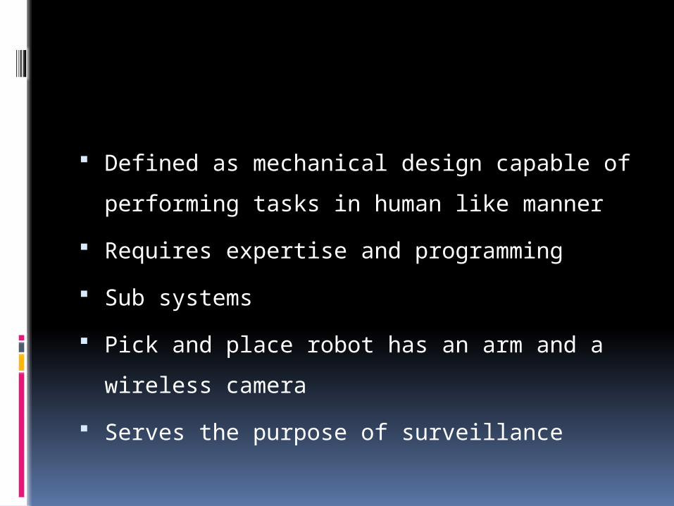
Defined as mechanical design capable of
performing tasks in human like manner
Requires expertise and programming
Sub systems
Pick and place robot has an arm and a
wireless camera
Serves the purpose of surveillance

AIM
Thus a machine that is
Compact
Rugged
Efficient
Capable of pick and place
Operate from a remote place
Controls motion of robotic arm

STEPS OF IMPLEMENTATION
Designer needs to be fully aware of
system requirements
Process begins with hardware design
o Mechanical design assembly
o Stable structure capable of bearing load

Electronic circuit is designed in ‘eagle’
o Microcontroller is chosen
o Circuit designed around it
Implementation of code
o Code is compiled using ‘KEIL’ compiler
Code tested on simulators
o Adjustments made on code
o Removal of errors
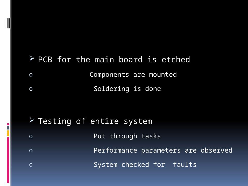
PCB for the main board is etched
o Components are mounted
o Soldering is done
Testing of entire system
o Put through tasks
o Performance parameters are observed
o System checked for faults

ELECTRONIC ASPECT

BLOCK DIAGRAM

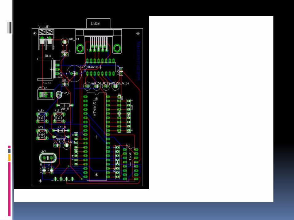
MAIN CIRCUIT DIAGRAM

WORKING OF MOTOR

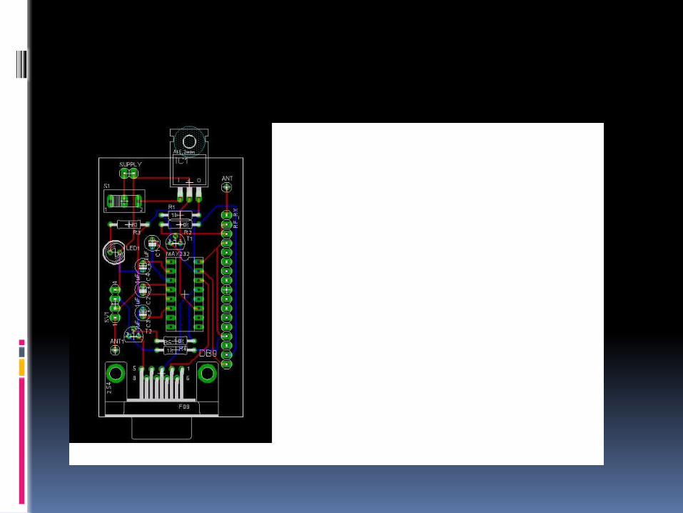
RF MODULE

MECHANICAL ASPECT

FEATURES OF THE MECHANICAL DESIN:
Two motors for running the wheels of the robot.
Two motors for the movement of robotic arm.
Movement up and down
Movement of jaw open and close
Wireless Camera on top of the assembly
Rectangular metal box as the base
A Belt around wheels, in order to save on the usage of hardware.

TOP VIEW

SIDE VIEW
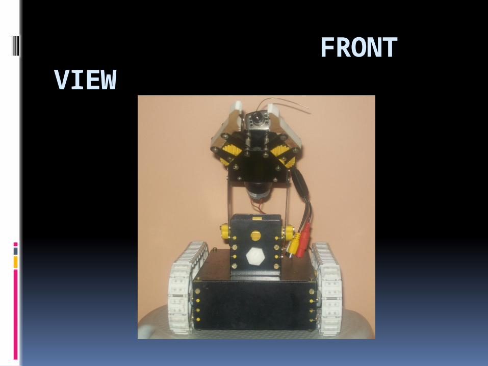
FRONT VIEW

SOFTWARE ASPECT

Q. WHY KIEL?
ANSWER:
For coding the CPU, we have utilized the KEIL software.
It enables the programmer to use high level languages
such as C to code the microcomputer.
KEIL encases and supports a well equipped chip library
from a variety of manufacturers.
It supports various register architectures which can be
incorporated in the code by including a header file.

WINDOW OF KEIL COMPILER


PCB DESIGNING

Easily Applicable Graphical Layout Editor(EAGLE)


APPLICATIONS:
Military applications Surveillance device
To pull out casualties
Can be used to transport objects just
on a click of a button
Industrial applications Loading of objects
Serving security purposes
Surveillance
Reaching places out of human reach

ADVANTAGES:
Wireless
Simple design
Reliable
Easy up gradation
Organized control

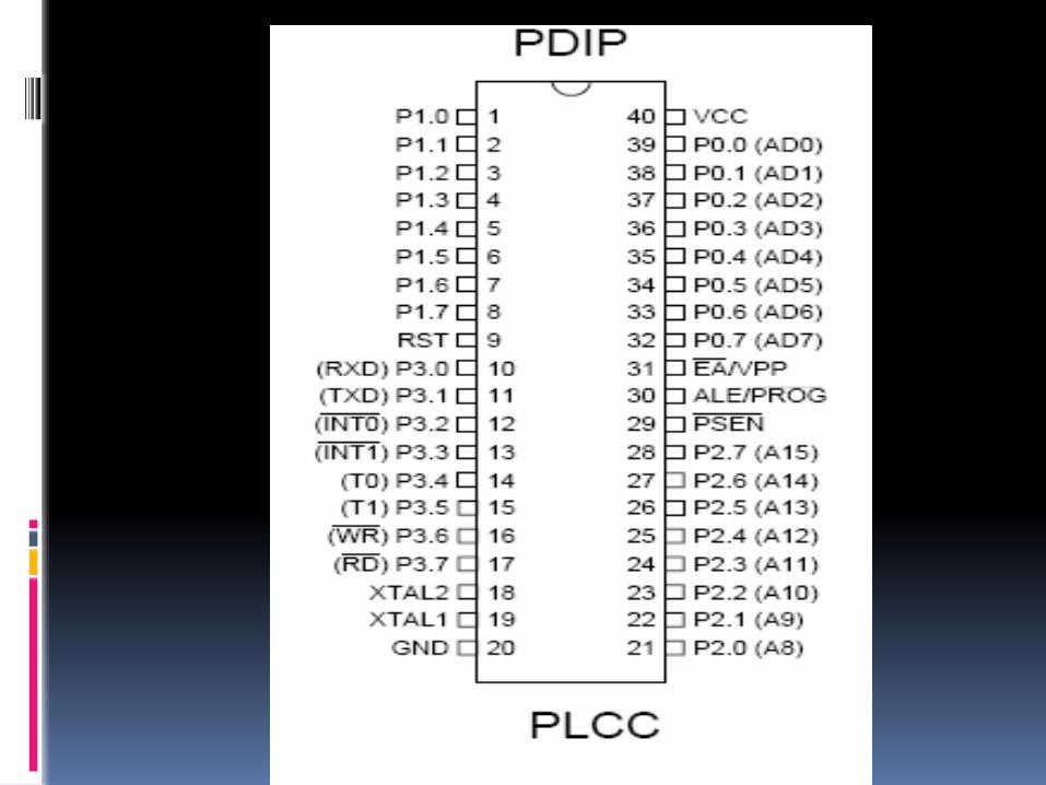
89C51 MICROCONTROLLER

FEATURES
Compatible with MCS-51™ Products
4K Bytes of In-System Reprogrammable Flash Memory
Fully Static Operation: 0 Hz to 24 MHz
Three-level Program Memory Lock
128 x 8-bit Internal RAM
32 Programmable I/O Lines
Two 16-bit Timer/Counters
Six Interrupt Sources
Programmable Serial Channel
Low-power Idle and Power-down Modes

7805 VOLTAGE
REGULATOR

FEATURES
Output Current up to 1A
Output Voltages of 5, 6, 8, 9, 10, 12, 15, 18, 24V
Thermal Overload Protection
Short Circuit Protection
Output Transistor Safe Operating Area Protection

L293D LINE DRIVER
600mA Output current capability per
channel
Over temperature protection
Logical “0” input voltage up to 1.5 v
Internal clamp diodes

High voltage, high current four channel driver
Accepts TTL logic levels
Drives inductive loads (DC motors)
Each channel has enable input
Suitable for use in switching applications at
freq up to 5 KHZ

PIN CONNECTIONS

Microcontroller insufficient to drive
motors
L293D consists of array of darling ton
current amplifiers
It helps to boost supply to motors

INTERFACING OF L293D WITH MICROCONTROLLER

DC MOTORS
Low torque and high speed devices
Gear set can be used to increase torque at the
cost of speed
The movement of shaft is smooth
Easiest to operate
Can rotate in both directions
Thus speed needs to be controlled to handle it

RESULT AND CONCLUSION