
Pic Prgm Manual
56
EMBEDDED SYSTEM LAB MANUAL 1 Vi Microsystems Pvt.Ltd.. EMBEDDED SYSTEM LAB MANUAL EXPERIMENTAL PROGRAMS USING PIC16F877A CONTROLLER Technical Clarification /Suggestion : Technical Support Division, Vi Microsystems Pvt. Ltd., Plot No :75,Electronics Estate, Perungudi,Chennai - 600 096,INDIA. Ph: 91- 44-2496 1842, 91-44-2496 1852 Mail : [email protected], Web : www.vimicrosystems.com
description
Pic program manual...... for embedded
Transcript of Pic Prgm Manual

EMBEDDED SYSTEM LAB MANUAL
1 Vi Microsystems Pvt.Ltd..
EMBEDDED SYSTEM LAB MANUAL
EXPERIMENTAL PROGRAMS USING PIC16F877A CONTROLLER
Technical Clarification /Suggestion :
Technical Support Division, Vi Microsystems Pvt. Ltd., Plot No :75,Electronics Estate, Perungudi,Chennai - 600 096,INDIA. Ph: 91- 44-2496 1842, 91-44-2496 1852 Mail : [email protected], Web : www.vimicrosystems.com

EMBEDDED SYSTEM LAB MANUAL
2 Vi Microsystems Pvt.Ltd..
CONTENTS INTRODUCTION
LIST OF EXPERIMENTS
1.VOLTAGE MEASUREMENT
2.WATER PUMP CONTROLLER
3.DIGITAL CLOCK
4.TEMPERATURE MEASUREMENT
5.PC COMMUNICATION
6.RF TRANSMITER AND RECEIVER
7.HOT CHAMPER CONTROLLER
8.OBSTACLE DETECTION THROUGH ULTRASONIC SENSOR.
9.SPRINKLER CONTROLLER
10. LAMP CONTROLLER

EMBEDDED SYSTEM LAB MANUAL
3 Vi Microsystems Pvt.Ltd..
INTRODUCTION EMBEDDED SYSTEMS An embedded system is a special-purpose computer system designed to perform one or a few dedicated functions, often with real-time computing constraints. It is usually embedded aspart of a complete device including hardware and mechanical parts. In contrast, a generalpurposecomputer, such as a personal computer, can do many different tasks depending onprogramming. Embedded systems control many of the common devices in use today FEATURES OF EMBEDDED SYSTEMS i. Cost Micro controllers with the supplementary circuit components are much cheaper than a computer with an analog and digital I/O. ii. Size and Weight Micro controllers are compact and light compared to computers. iii. Simple applications If the application requires very few number of I/O and the code is relatively small, which donot require extended amount of memory and a simple LCD display is sufficient as a userinterface, a microcontroller would be suitable for this application. iv. Reliability Since the architecture is much simpler than a computer it is less likely to fail. v. Speed All the components on the microcontroller are located on a single piece of silicon. Hence, the applications run much faster than it does on a computer.
FEATURES OF PIC16F877 High-Performance RISC CPU * Only 35 single-word instructions to learn. * All single-cycle instructions except for program branches, which are twocycle. * Operating speed: DC – 20 MHz clock input DC – 200 ns instruction cycle. * Up to 8K x 14 words of Flash Program Memory, Up to 368 x 8 bytes of Data Memory (RAM), Up to 256 x 8 bytes of EEPROM Data Memory. * Pin out compatible to other 28-pin or 40/44-pin PIC16CXXX and PIC16FXXX micro controllers. Peripheral Features * Timer0: 8-bit timer/counter with 8-bit prescaler.
EMBEDDED SYSTEM LAB MANUAL
4 Vi Microsystems Pvt.Ltd..
* Timer1: 16-bit timer/counter with prescaler, can be incremented during Sleep via external crystal/clock. * Timer2: 8-bit timer/counter with 8-bit period register, prescaler and postscaler. * Two Capture, Compare, PWM modules. - Capture is 16-bit, max. Resolution is 12.5 ns - Compare is 16-bit, max. Resolution is 200 ns - PWM max. Resolution is 10-bit * Synchronous Serial Port (SSP) with SPI™ (Master mode) and I2C™ (Master/Slave). * Universal Synchronous Asynchronous Receiver Transmitter (USART/SCI) with 9-bit address detection. * Parallel Slave Port (PSP) – 8 bits wide with external RD, WR and CS controls (40/44-pin only). * Brownout detection circuitry for Brown-out Reset (BOR).
Analog Features * 10-bit, up to 8-channel Analog-to-Digital Converter (A/D). * Brownout Reset (BOR). * Analog Comparator module with: - Two analog comparators. - Programmable on-chip voltage reference (VREF) module. - Programmable input multiplexing from device inputs and internal voltage reference. - Comparator outputs are externally accessible. Special Micro controller Features * 100,000-erase/write cycle Enhanced Flash program memory typical. * 1,000,000-erase/write cycle Data EEPROM memory typical. * Data EEPROM Retention > 40 years. * Self-re-programmable under software control. * In-Circuit Serial Programming™ (ICSP™ ) via two pins. * Single-supply 5V In-Circuit Serial Programming. * Watchdog Timer (WDT) with its own on-chip RC oscillator for reliable operation. * Programmable code protection. * Power saving Sleep mode. * Selectable oscillator options. * In-Circuit Debug (ICD) via two pins. Application * Industrial control * Medical systems * Access control * Point-of-sale * Communication gateway * Embedded soft modem * General purpose applications

EMBEDDED SYSTEM LAB MANUAL
5 Vi Microsystems Pvt.Ltd..
PIN TERMINATION OF 16F877A CONTROLLER IN (P8 VPIC BUS )

EMBEDDED SYSTEM LAB MANUAL
6 Vi Microsystems Pvt.Ltd..
EX NO:1 VOLTAGE MEASUREMENT
AIM:
ToWrite a ‘C’ Program to measure voltage from 0 to 5 volts and display on 2 digits 7 segment displays.
APPARATUS REQUIRED
1. PIC16F877A KIT 2. 5 V ADAPTER 3. RS232 CABLE.
SOFTWARE USED
1. MPLAB IDE COMPILER. 2. PIC ISP DOWNLOADER.
PROGRAM
#include<16f877.h>
#use delay(clock=20000000)
#use rs232(baud=9600,xmit=pin_c6,rcv=pin_c7)
#use I2C(master, sda=PIN_C4, scl=PIN_C3)
long int value;
int i=0;
unsigned char arr[10]={0x3f,0x06,0x5b,0x4f,0x66,0x6d,0x7d,0x07,0x7f,0x67};
void write_seg(int x1,int x2)
{
unsigned char x=0;
x=(arr[x1]|0x80);
i2c_start();
i2c_write(0x40);
i2c_write(arr[x1]|0x80);
EMBEDDED SYSTEM LAB MANUAL
7 Vi Microsystems Pvt.Ltd..
i2c_stop();
i2c_start();
i2c_write(0x42);
i2c_write(arr[x2]);
i2c_stop();
}
void main()
{
setup_adc_ports( RA0_ANALOG );
setup_adc(ADC_CLOCK_INTERNAL );
while(1)
{set_adc_channel( 0 );
value = read_adc();
i=((value*50)/255);
write_seg(i/10,i%10);
//printf(" %d.%d \n\r",i/10,i%10);
}
}
PROCEDURE
1. Compile the above ‘C’Program using MPLAB IDE Software to create HEX file 2. Down Load the HEX file using PICISP software . 3. Vary the Potmeter, which is connected to ADC Channel 0(TP1) 4. While varying the Potmeter, the corresponding digitin the 7 segment (0-5V) will also
vary automatically.
RESULT
Thus the voltmeter is designed to measure voltages from 0 to 5v in the 7 segment display and the ‘C’ program was compiled and executed successfully.

EMBEDDED SYSTEM LAB MANUAL
8 Vi Microsystems Pvt.Ltd..
EX NO:2 WATER LEVEL CONTROLLER
AIM:
Design a water Pumb controller by sensing the low and high level in the water tank.
APPARATUS REQUIRED
1. PIC16F877A KIT 2. 5 V ADAPTER 3. RS232 CABLE. 4. ITB 003 Module.
SOFTWARE USED
1. MPLAB IDE COMPILER. 2. PIC ISP DOWNLOADER.
PROGRAM
#include<16f877a.h>
#include<stdio.h>
#use delay(clock=20000000)
#use rs232(baud=9600,xmit=PIN_C6,rcv=PIN_C7)
volatile int a=0,b=0;
void main()
{
while(1)
{
a=input(PIN_D0);
b=input(PIN_D1);
printf("\n\r %d %d ",a,b);
b=a&b;
printf("%d",b);

EMBEDDED SYSTEM LAB MANUAL
9 Vi Microsystems Pvt.Ltd..
if(b == 0)
{
output_high(PIN_D4); // MOT
output_high(PIN_D6); // LED:RED
output_low(PIN_D7); // LED:GREEN
}
else
{
output_low(PIN_D4); // MOT
output_low(PIN_D6); // LED:GREEN
output_high(PIN_D7); // LED:RED
}
if(a==0)
{
output_low(PIN_D6); // LED:GREEN
}
}
}
EMBEDDED SYSTEM LAB MANUAL
10 Vi Microsystems Pvt.Ltd..
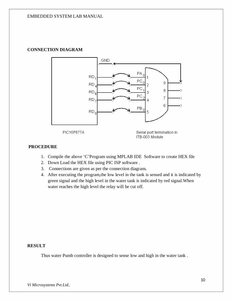
CONNECTION DIAGRAM
PROCEDURE
1. Compile the above ‘C’Program using MPLAB IDE Software to create HEX file 2. Down Load the HEX file using PIC ISP software . 3. Connections are given as per the connection diagram. 4. After executing the program,the low level in the tank is sensed and it is indicated by
green signal and the high level in the water tank is indicated by red signal.When water reaches the high level the relay will be cut off.
RESULT
Thus water Pumb controller is designed to sense low and high in the water tank .
EMBEDDED SYSTEM LAB MANUAL
11 Vi Microsystems Pvt.Ltd..
EX NO:3 DIGITAL CLOCK
AIM:
ToWrite a ‘C’ Program to display the Real Time Clock in the LCD display.
APPARATUS REQUIRED
1. PIC16F877A KIT 2. 5 V ADAPTER 3. RS232 CABLE. 4. RTC BOARD
SOFTWARE USED
1. MPLAB IDE COMPILER. 2. PIC ISP DOWNLOADER.
PROGRAM
#include <16F877A.H>
#use delay(clock=20000000)
#use rs232(baud=9600, xmit=PIN_C6, rcv=PIN_C7)
#use I2C(master, sda=PIN_C4, scl=PIN_C3)
void set_rtc_time();
void get_rtc_time();
void lcd_init();
void delay(unsigned long del);
void lcd_cmd(unsigned char cmd);
void lcd_dat(unsigned char dat);

EMBEDDED SYSTEM LAB MANUAL
12 Vi Microsystems Pvt.Ltd..
unsigned char time[]={0X56,0X38,0X10,0X01,0X01,0X11};
unsigned char readtime[0X06];
unsigned long int hour,second,minute,date,month,year;
unsigned int i;
unsigned char rtc[13];
unsigned char initi[5]={0x38,0x01,0x06,0x0C,0x80};
char x[]="REALTIME:";
void data_display(char x[])
{
output_high(pin_E0);
output_low(pin_E1);
output_low(pin_E2);
for(i=0;x[i]!='\0';i++)
{
output_D(x[i]);
output_high(pin_E2);
delay_us(500);
output_low(pin_E2);
}
}
void data_display1(unsigned char rtc[])
EMBEDDED SYSTEM LAB MANUAL
13 Vi Microsystems Pvt.Ltd..
{
output_high(pin_E0);
output_low(pin_E1);
output_low(pin_E2);
for(i=0;x[i]!='\0';i++)
{
output_D(rtc[i]);
output_high(pin_E2);
delay_us(500);
output_low(pin_E2);
}
}
void main()
{
lcd_init();
data_display(x);
set_rtc_time();
while(1)
{
get_rtc_time();
printf("T: %x : %x : %x \t",hour,minute,second);

EMBEDDED SYSTEM LAB MANUAL
14 Vi Microsystems Pvt.Ltd..
sprintf(rtc,"%02x:%02x:%02x ",hour,minute,second);
lcd_cmd(0xc0);
data_display1(rtc);
}
}
void set_rtc_time()
{
i2c_start();
i2c_write(0xa0);
i2c_write(0x02);
i2c_write(0x55);
i2c_write(0x15);
i2c_write(0x05);
i2c_stop();
}
void get_rtc_time()
EMBEDDED SYSTEM LAB MANUAL
15 Vi Microsystems Pvt.Ltd..
{
i2c_start();
i2c_write(0xa0);
i2c_write(0x02);
i2c_stop();
i2c_start();
i2c_write(0xa1);
second = i2c_read(0);
i2c_stop();
i2c_start();
i2c_write(0xa0);
i2c_write(0x03);
i2c_stop();
i2c_start();
i2c_write(0xa1);
minute = i2c_read(0);
i2c_stop();
i2c_start();
i2c_write(0xa0);
i2c_write(0x04);

EMBEDDED SYSTEM LAB MANUAL
16 Vi Microsystems Pvt.Ltd..
i2c_stop();
i2c_start();
i2c_write(0xa1);
hour = i2c_read(0);
i2c_stop();
}
void delay(unsigned long del)
{
while(del=del-1);
}
void lcd_cmd(unsigned char cmd)
{
output_low(pin_E0);
output_low(pin_E1);
delay(500);
output_d(cmd);
delay(500);
output_high(pin_E2);
delay(500);
output_low(pin_E2);
EMBEDDED SYSTEM LAB MANUAL
17 Vi Microsystems Pvt.Ltd..
}
void lcd_init()
{
unsigned int k=0;
for(k=0;k<5;k++)
{
lcd_cmd(initi[k]);
}
}
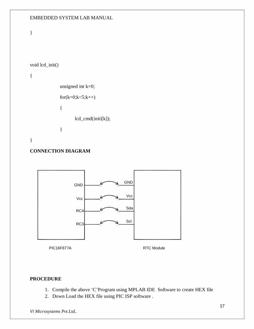
CONNECTION DIAGRAM
Vcc
RC4
RC3
GND
PIC16F877A RTC Module
Vcc
Sda
Scl
GND
PROCEDURE
1. Compile the above ‘C’Program using MPLAB IDE Software to create HEX file 2. Down Load the HEX file using PIC ISP software .

EMBEDDED SYSTEM LAB MANUAL
18 Vi Microsystems Pvt.Ltd..
3. Connections are given as per the connection diagram. 4. After executing the program,the time will be displayed in the LCD display.
RESULT
Thus the digital clock is designed to display the time in the LCD display .

EMBEDDED SYSTEM LAB MANUAL
19 Vi Microsystems Pvt.Ltd..
EX NO:4 TEMPERATURE MEASUREMENT
AIM:
ToWrite a ‘C’ Program to display temperature value in the 7 segment using LM35 sensor.
APPARATUS REQUIRED
1. PIC16F877A KIT 2. 5 V ADAPTER 3. RS232 CABLE. 4. LM35 SENSOR
SOFTWARE USED
1. MPLAB IDE COMPILER. 2. PIC ISP DOWNLOADER.
THEORY
The are many cool sensors available now a days, ranging from IR distance sensor modules, accelerometers, humidity sensors, temperature sensors and many many more(gas sensors, alcohol sensor, motion sensors, touch screens). Many of these are analog in nature. That means they give a voltage output that varies directly (and linearly) with the sensed quantity. For example in LM35 temperature sensor, the output voltage is 10mV per degree centigrade. That means if output is 300mV then the temperature is 30 degrees. In this tutorial we will learn how to interface LM35 temperature sensor with PIC18F77A microcontroller and display its output on the 7 segment display.
EMBEDDED SYSTEM LAB MANUAL
20 Vi Microsystems Pvt.Ltd..
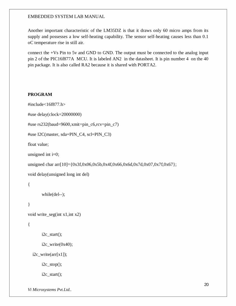
Another important characteristic of the LM35DZ is that it draws only 60 micro amps from its supply and possesses a low self-heating capability. The sensor self-heating causes less than 0.1 oC temperature rise in still air.
connect the +Vs Pin to 5v and GND to GND. The output must be connected to the analog input pin 2 of the PIC16f877A MCU. It is labeled AN2 in the datasheet. It is pin number 4 on the 40 pin package. It is also called RA2 because it is shared with PORTA2.
PROGRAM
#include<16f877.h>
#use delay(clock=20000000)
#use rs232(baud=9600,xmit=pin_c6,rcv=pin_c7)
#use I2C(master, sda=PIN_C4, scl=PIN_C3)
float value;
unsigned int i=0;
unsigned char arr[10]={0x3f,0x06,0x5b,0x4f,0x66,0x6d,0x7d,0x07,0x7f,0x67};
void delay(unsigned long int del)
{
while(del--);
}
void write_seg(int x1,int x2)
{
i2c_start();
i2c_write(0x40);
i2c_write(arr[x1]);
i2c_stop();
i2c_start();
EMBEDDED SYSTEM LAB MANUAL
21 Vi Microsystems Pvt.Ltd..
i2c_write(0x42);
i2c_write(arr[x2]);
i2c_stop();
}
void main()
{
setup_adc_ports( ALL_ANALOG );
setup_adc(ADC_CLOCK_INTERNAL );
while(1)
{
set_adc_channel( 2 );
value = read_adc();
value = value;
i=((int)(value));
i=(i*2);
printf(" Temperature in Cel %d \n\r",i);
if(i>=99){i=99;}
write_seg(i/10,i%10);
delay(48000);
}
}

EMBEDDED SYSTEM LAB MANUAL
22 Vi Microsystems Pvt.Ltd..
CONNECTION DIAGRAM
GND
Vcc
RA2
GND
Vcc
o/p
PIC16F877A
VI Sense 17Module
PROCEDURE
1. Connections are given as per the connection diagram. 2. Compile the above ‘C’Program using MPLAB IDE Software to create HEX file 3. Down Load the HEX file using PIC ISP software . 4. After executing the program,the corresponding temperature wil be displayed in the 7
segment.
RESULT
Thus the ‘C’ Program was written to display the temperature value in the 7 segment using LM35 sensor

EMBEDDED SYSTEM LAB MANUAL
23 Vi Microsystems Pvt.Ltd..
EX NO:5 PC COMMUNICATION
AIM:
ToWrite a ‘C’ Program to display the message in the serial window.
APPARATUS REQUIRED
1. PIC16F877A KIT 2. 5 V ADAPTER 3. RS232 CABLE.
SOFTWARE USED
1. MPLAB IDE COMPILER. 2. PIC ISP DOWNLOADER 3. WINX TALK
PROGRAM
#include<16f877a.h>
#include<stdio.h>
#use delay(clock=20000000)
#use rs232(baud=9600,xmit=PIN_C6,rcv=PIN_C7)
void main()
{
while(1)
{
printf(" Vi Microsystems Pvt Ltd Chennai-95 \n");
}
}
PROCEDURE
1. Compile the above ‘C’Program using MPLAB IDE Software to create HEX file 2. Down Load the HEX file using PIC ISP software . 3. After executing the program,the message “Vi Microsystems Pvt Ltd Chennai-95” will
be seen in the WINX TALK communication window with 9600 baudrate.
EMBEDDED SYSTEM LAB MANUAL
24 Vi Microsystems Pvt.Ltd..
RESULT
Thus the above ‘C’program to display the message in the serial window was executed and verified successfully.

EMBEDDED SYSTEM LAB MANUAL
25 Vi Microsystems Pvt.Ltd..
EX NO:6 REMOTE CONTROL THROUGH FM LINK
AIM:
ToWrite a ‘C’ Program to establish a remote link between two microcontroller using RF transmitter and receiver and send the message “abcd” from the transmitter side to receiver side.
APPARATUS REQUIRED
1. PIC16F877A KIT 2. 5 V ADAPTER 3. RS232 CABLE.
SOFTWARE USED
1. MPLAB IDE COMPILER. 2. PIC ISP DOWNLOADER
PROGRAM IN TRANSMITTER SIDE
#include<16f877a.h>
#include<stdio.h>
#use delay(clock=20000000)
#use rs232(baud=1200,xmit=pin_C6,rcv=pin_C7)
unsigned char receive[5];
unsigned char a='a';
unsigned char b='b';
unsigned char c[4]="abc";
int i;
int j;
void rx()
{
unsigned int i;
for(i=0;i<5;i++)
{
EMBEDDED SYSTEM LAB MANUAL
26 Vi Microsystems Pvt.Ltd..
receive[i]=getch();
}
}
void tx(unsigned char y[])
{
for(i=0;y[i]!='\0';i++)
{
putchar(y[i]);
}
}
void wait(int z)
{
int i;
for(i=0;i<z;i++){}
}
void main()
{
while(1)
{
for(j=0;j<10000;j++)
{
printf("%c",a);

EMBEDDED SYSTEM LAB MANUAL
27 Vi Microsystems Pvt.Ltd..
}
}
}
PROGRAM IN RECEIVER SIDE
#include<16f877.h>
#include<stdio.h>
#use delay(clock=20000000)
#use rs232(baud=1200,xmit=pin_c6,rcv=pin_c7)
unsigned int i;
unsigned char a;
void delay(unsigned long del)
{
while(del--);
}
void lcd_cmd(unsigned char cmd)
{
output_low(pin_E0);
output_low(pin_E1);
delay(500);
EMBEDDED SYSTEM LAB MANUAL
28 Vi Microsystems Pvt.Ltd..
output_D(cmd);
delay(500);
output_high(pin_E2);
delay(500);
output_low(pin_E2);
}
void lcd_dat(unsigned char dat)
{
output_high(pin_E0);
output_low(pin_E1);
delay(500);
output_D(dat);
delay(500);
output_high(pin_E2);
delay(500);
output_low(pin_E2);
}
void lcd_init(void)
{
lcd_cmd(0X38);
delay(500);
lcd_cmd(0X06);
delay(500);

EMBEDDED SYSTEM LAB MANUAL
29 Vi Microsystems Pvt.Ltd..
lcd_cmd(0X0C);
delay(500);
lcd_cmd(0X01);
delay(500);
lcd_cmd(0X80);
delay(500);
}
void print()
{
lcd_disp(arr1,0xC0);
}
void main()
{
lcd_init();
while(1)
{
a=getch();
printf("%c",a);
lcd_cmd(0x8d);

EMBEDDED SYSTEM LAB MANUAL
30 Vi Microsystems Pvt.Ltd..
lcd_dat(a); }
}
CONNECTION DIAGRAM IN TRANSMITTER SIDE
EMBEDDED SYSTEM LAB MANUAL
31 Vi Microsystems Pvt.Ltd..
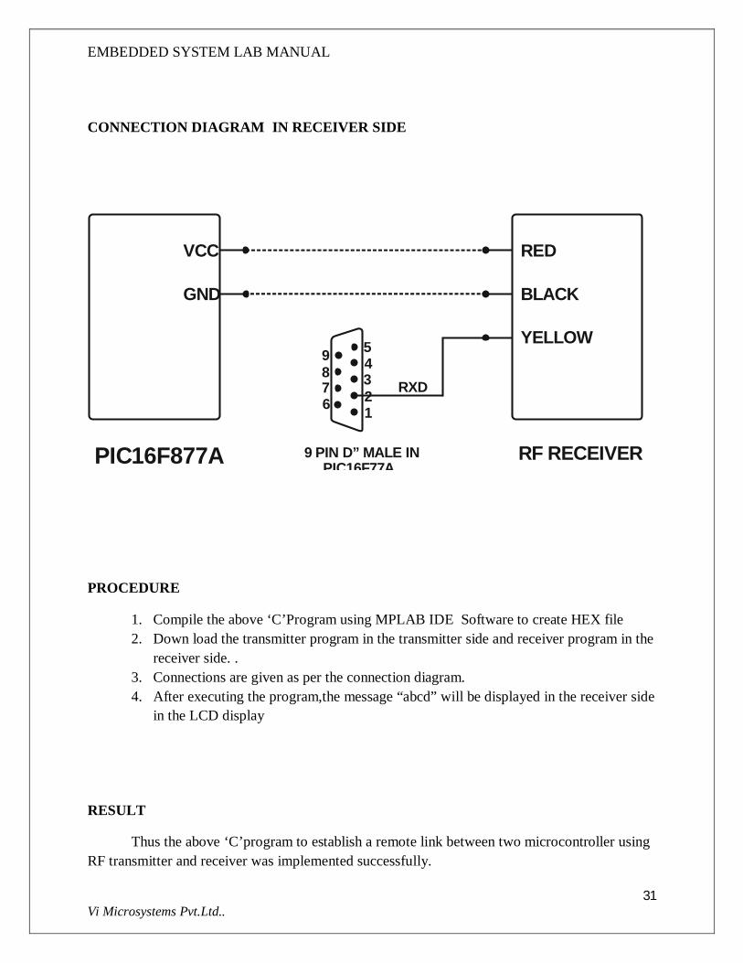
CONNECTION DIAGRAM IN RECEIVER SIDE
PIC16F877A
RED
BLACK
YELLOW54321
VCC
GND
RF RECEIVER9 PIN D” MALE IN PIC16F77A
RXD
9876
PROCEDURE
1. Compile the above ‘C’Program using MPLAB IDE Software to create HEX file 2. Down load the transmitter program in the transmitter side and receiver program in the
receiver side. . 3. Connections are given as per the connection diagram. 4. After executing the program,the message “abcd” will be displayed in the receiver side
in the LCD display
RESULT
Thus the above ‘C’program to establish a remote link between two microcontroller using RF transmitter and receiver was implemented successfully.

EMBEDDED SYSTEM LAB MANUAL
32 Vi Microsystems Pvt.Ltd..
EX NO:7 HOT CHAMBER CONTROLLER
AIM:
Towrite a ‘C’ Program to design a hot chamber to maintain the temperature say at 40 degree centigrade.
APPARATUS REQUIRED
1. PIC16F877A KIT 2. 5 V ADAPTER 3. RS232 CABLE 4. AD590 SENSOR 5. MINI FURNANCE 6. TEMPERATURE ON/OFF CONTROLLER.
SOFTWARE USED:
1. MPLAB IDE COMPILER. 2. PIC ISP DOWNLOADER 3. WINX TALK
THEORY
The AD590 is a two-terminal integrated circuit temperaturetransducer which produces an output current proportionalto absolute temperature. For supply voltages between +4Vand +30V the device acts as a high impedance, constantcurrent regulator passing 1mA/K. Laser trimming of thechip's thin film resistors is used to calibrate the device to298.2mA output at 298.2 Kelvin (+258C).The AD590 is particularly useful in remote sensingapplications. The AD590 is insensitive to voltage dropsover long lines due to its high impedance current output.Any well-insulated shielded twisted pair is sufficient foroperation hundreds of feet from the receiving circuitry.
PROGRAM
#include<16f877.h>
#use delay(clock=20000000)
#use rs232(baud=9600,xmit=pin_c6,rcv=pin_c7)
float value;
unsigned int i=0;

EMBEDDED SYSTEM LAB MANUAL
33 Vi Microsystems Pvt.Ltd..
void main()
{
while(1)
{
setup_adc_ports( ALL_ANALOG );
setup_adc(ADC_CLOCK_INTERNAL );
set_adc_channel( 1 );
value = read_adc();
i=(int)(value*0.3);
printf(" %d \n\r",i);
if(i>40)
{
output_low(PIN_D0);
printf(" Above ");
}
else if(i<35)
{
output_high(PIN_D0);
printf(" Below ");
}
}
}

EMBEDDED SYSTEM LAB MANUAL
34 Vi Microsystems Pvt.Ltd..
CONNECTION DIAGRAM
PROCEDURE
1. Connections are given as per the connection diagram. 2. Compile the above ‘C’Program using MPLAB IDE Software to create HEX file 3. Down Load the HEX file using PIC ISP software .

EMBEDDED SYSTEM LAB MANUAL
35 Vi Microsystems Pvt.Ltd..
4. After executing the program, the relay connected to the RD0 will be cut off after the temperature exceeds 40 degree centigrade which will be displayed in the communication port.
RESULT
Thus a hot chamber was designed to maintain the temperature say at 40 degrees centigrade and ‘C’ Program was compiled and executed successfully.

EMBEDDED SYSTEM LAB MANUAL
36 Vi Microsystems Pvt.Ltd..
EX NO: 8 OBSTACLE DETECTOR USING ULTRASONIC
AIM:
Towrite a ‘C’ Program to design an obstacle detection system using ultrasonic transmitter receiver.
APPARATUS REQUIRED
1. PIC16F877A KIT 2. 5 V ADAPTER 3. RS232 CABLE 4. ULTRA SONIC SENSOR MODULE
SOFTWARE USED:
1. MPLAB IDE COMPILER. 2. PIC ISP DOWNLOADER
THEORY
The Ultrasonic distance sensor consists of a ultrasonic transducer mounted on a small PCB, with mounting holes. It can detect objects 0-in. to 254-in. (6.45-meters), and range objects 6-in. to 254-in. (6.45 meters). Ultrasonic sensors are more of a shotgun distance sensor, as opposed to the 'laser beam' IR

EMBEDDED SYSTEM LAB MANUAL
37 Vi Microsystems Pvt.Ltd..
distance sensor. Use the IR distance sensor for targeted distance measurement, and the ultrasonic distance sensor for wide-range applications. Car based applications include, backup sensors, parking sensors, curb sensors, and more. Home automation applications include room monitoring, garage parking sensors, and more.
This UltraSonic Distance Sensor is perfect for any number of applications that require you to perform measurements between moving or stationary objects. Naturally, robotics applications are very popular but you'll also find this product to be useful in security systems or as an infrared replacement if so desired.This is extreamily suitable for Roboic Application, since it need only one I/O pin and very fast. The "ECHO" does not require any ADC or USART to meassure the distance. Since it is very stable ,the "ECHO" Ultrasonic sensor module can be used for Micromouse application instead of IR sensor.
PROGRAM
#include<16f877a.h>
#include<stdlib.h>
#include<string.h>
#include<stdio.h>
#use delay(clock=20000000)
#use rs232(baud=9600,xmit=pin_c6,rcv=pin_c7,stream=GPS)
int i=0;int a1;char a[];
void delay(unsigned long del)
{
while(del--);
}
void lcd_cmd(unsigned char cmd)
{

EMBEDDED SYSTEM LAB MANUAL
38 Vi Microsystems Pvt.Ltd..
output_low(pin_E0);
output_low(pin_E1);
delay(500);
output_D(cmd);
delay(500);
output_high(pin_E2);
delay(500);
output_low(pin_E2);
}
void lcd_dat(unsigned char dat)
{
output_high(pin_E0);
output_low(pin_E1);
delay(500);
output_D(dat);
delay(500);
output_high(pin_E2);
delay(500);
output_low(pin_E2);
}
void lcd_init(void)
{

EMBEDDED SYSTEM LAB MANUAL
39 Vi Microsystems Pvt.Ltd..
lcd_cmd(0X38);
delay(500);
lcd_cmd(0X06);
delay(500);
lcd_cmd(0X0C);
delay(500);
lcd_cmd(0X01);
delay(500);
lcd_cmd(0X80);
delay(500);
}
void lcd_disp(unsigned char w[],unsigned char add)
{
unsigned char i=0;
for(i=0;w[i]!='\0';i++)
{
lcd_cmd(add+i);
lcd_dat(w[i]);
delay(500);
}
}
void lcd_con(unsigned int con)
{

EMBEDDED SYSTEM LAB MANUAL
40 Vi Microsystems Pvt.Ltd..
lcd_dat(((con%1000)/100)+0x30);
lcd_dat(((con%100)/10)+0x30);
lcd_dat((con%10)+0x30);
}
void print()
{
unsigned char arr[]={"DISTANCE IN CMS"};
lcd_disp(arr,0x80);
}
void get()
{
do{;}while(getc()!='R');
a1=( (getc()-48)*100)+( (getc()-48)*10)+ (getc()-48);
}
void main()
EMBEDDED SYSTEM LAB MANUAL
41 Vi Microsystems Pvt.Ltd..
{
lcd_init();
print();
while(1)
{
while(1)
{
get();
lcd_cmd(0xC0);
lcd_con(a1);
}
}
}

EMBEDDED SYSTEM LAB MANUAL
42 Vi Microsystems Pvt.Ltd..
CONNECTION DIAGRAM
PIC16F8 77A
RED
BLACK
YELLOW54321
VCC
GND
ULTRASONIC SENSOR MODULE
O/P
9 PIN D” MALE IN PIC16F77A
GND
VCC
9876
PROCEDURE
1. First Compile the above ‘C’Program using MPLAB IDE Software to create HEX file 2. Down Load the HEX file using PIC ISP software . 3. Connections are given as per the connection diagram. 4. After executing the program, the distance covered by the ultrasonic sensor is
displayed in the LCD.
RESULT:
Thus an obstacle detection system was designed using ultrasonic sensor and ‘C’ Program was compiled and executed successfully

EMBEDDED SYSTEM LAB MANUAL
43 Vi Microsystems Pvt.Ltd..
EX NO: 9 SPRINKLER CONTROLLER
AIM:
Towrite a ‘C’ Program to design a moisture sensor and sprinkler controller.
APPARATUS REQUIRED
1. PIC16F877A KIT 2. 5 V ADAPTER 3. RS232 CABLE 4. MOISTURE SENSOR MODULE. 5. SPRINKLER CONTROLLER MODULE.
SOFTWARE USED
1. MPLAB IDE COMPILER. 2. PIC ISP DOWNLOADER 3. WINX TALK
THEORY
Fig 9..humidity sensor
Humidity is the presence of water in air. The amount of water vapor in air can affect human comfort as well as many manufacturing processes in industries. The presence of water vapor also influences various physical, chemical, and biological processes.
Humidity measurement in industries is critical because it may affect the business cost of the product and the health and safety of the personnel. Hence, humidity sensing is very important, especially in the control systems for industrial processes and human comfort.

EMBEDDED SYSTEM LAB MANUAL
44 Vi Microsystems Pvt.Ltd..
Controlling or monitoring humidity is of paramount importance in many industrial & domestic applications. In semiconductor industry, humidity or moisture levels needs to be properly controlled & monitored during wafer processing. In medical applications, humidity control is required for respiratory equipments, sterilizers, incubators, pharmaceutical processing, and biological products. Humidity control is also necessary in chemical gas purification, dryers, ovens, film desiccation, paper and textile production, and food processing. In agriculture, measurement of humidity is important for plantation protection (dew prevention), soil moisture monitoring, etc. For domestic applications, humidity control is required for living environment in buildings, cooking control for microwave ovens, etc. In all such applications and many others, humidity sensors are employed to provide an indication of the moisture levels in the environment.
PROGRAM
#include<16f877.h>
#use delay(clock=20000000)
#use rs232(baud=9600,xmit=pin_c6,rcv=pin_c7)
long int value;
int i=0;
void main()
{
while(1)
{
setup_adc_ports( ALL_ANALOG );
setup_adc(ADC_CLOCK_INTERNAL );
set_adc_channel( 1 );
value = read_adc();
i=(int)(value/2);
printf("MOISTURE SENSOR: %3d \n",i);
if(i>80)
{
output_low(PIN_D0);

EMBEDDED SYSTEM LAB MANUAL
45 Vi Microsystems Pvt.Ltd..
}
else
{
output_high(PIN_D0);
}
}
}
CONNECTION DIAGRAM

EMBEDDED SYSTEM LAB MANUAL
46 Vi Microsystems Pvt.Ltd..
PROCEDURE
1. Connections are given as per the connection diagram. 2. Compile the above ‘C’Program using MPLAB IDE Software to create HEX file 3. Down Load the HEX file using PIC ISP software . 4. Connect the output of humidity sensor to ADC input 1 (RA1) of the pic controller. 5. After executing the program, the relay connected to the RD0 will be cut off after the
sensor value exceeds 80,which will be displayed in the communication port AT 9600 baud rate.
RESULT:
Thus a moisture sensor and sprinkler controller was designed and ‘C’ Program was compiled and executed successfully.

EMBEDDED SYSTEM LAB MANUAL
47 Vi Microsystems Pvt.Ltd..
EX NO: 10 LAMP CONTROLLER
AIM:
To design a light sensor to control the lamp.
APPARATUS REQUIRED
PIC16F877A KIT 5 V ADAPTER RS232 CABLE RTC MODULE LDR SET UP.
SOFTWARE USED
MPLAB IDE COMPILER. PIC ISP DOWNLOADER WINX TALK.
THEORY
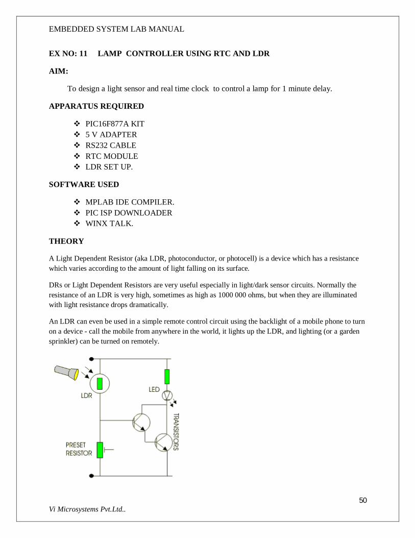
A Light Dependent Resistor (aka LDR, photoconductor, or photocell) is a device which has a resistance which varies according to the amount of light falling on its surface.
DRs or Light Dependent Resistors are very useful especially in light/dark sensor circuits. Normally the resistance of an LDR is very high, sometimes as high as 1000 000 ohms, but when they are illuminated with light resistance drops dramatically.
An LDR can even be used in a simple remote control circuit using the backlight of a mobile phone to turn on a device - call the mobile from anywhere in the world, it lights up the LDR, and lighting (or a garden sprinkler) can be turned on remotely.

EMBEDDED SYSTEM LAB MANUAL
48 Vi Microsystems Pvt.Ltd..
When the light level is low the resistance of the LDR is high. This prevents current from flowing to the base of the transistors. Consequently the LED does not light.However, when light shines onto the LDR its resistance falls and current flows into the base of the first transistor and then the second transistor. The LED lights.The preset resistor can be turned up or down to increase or decrease resistance, in this way it can make the circuit more or less sensitive.
PROGRAM
#include<16f877.h>
#use delay(clock=20000000)
#use rs232(baud=9600,xmit=pin_c6,rcv=pin_c7)
long int value;
int i=0;
void main()
{
while(1)
{
setup_adc_ports( ALL_ANALOG );
setup_adc(ADC_CLOCK_INTERNAL );
set_adc_channel( 1 );
value = read_adc();
i=(int)(value/2);
printf("LDR SENSOR: %3d \n",i);
if(i>80)
{
output_low(PIN_D0);
}
else
{

EMBEDDED SYSTEM LAB MANUAL
49 Vi Microsystems Pvt.Ltd..
output_high(PIN_D0);
}
}
}
CONNECTION DIAGRAM
PROCEDURE
Connections are given as per the connection diagram. Compile the above ‘C’Program using MPLAB IDE Software to create HEX file Down Load the HEX file using PIC ISP software . Connect the LDR output to the analog input 1 of microcontroller. After executing the program, the time will displayed in the communication port and
the Lamp connected to the RD1 will be glow for one minute delay
RESULT:
Thus the light sensor to control the lamp was designed and ‘C’ Program was compiled and
executed successfully.T
EMBEDDED SYSTEM LAB MANUAL
50 Vi Microsystems Pvt.Ltd..
EX NO: 11 LAMP CONTROLLER USING RTC AND LDR
AIM:
To design a light sensor and real time clock to control a lamp for 1 minute delay.
APPARATUS REQUIRED
PIC16F877A KIT 5 V ADAPTER RS232 CABLE RTC MODULE LDR SET UP.
SOFTWARE USED
MPLAB IDE COMPILER. PIC ISP DOWNLOADER WINX TALK.
THEORY
A Light Dependent Resistor (aka LDR, photoconductor, or photocell) is a device which has a resistance which varies according to the amount of light falling on its surface.
DRs or Light Dependent Resistors are very useful especially in light/dark sensor circuits. Normally the resistance of an LDR is very high, sometimes as high as 1000 000 ohms, but when they are illuminated with light resistance drops dramatically.
An LDR can even be used in a simple remote control circuit using the backlight of a mobile phone to turn on a device - call the mobile from anywhere in the world, it lights up the LDR, and lighting (or a garden sprinkler) can be turned on remotely.

EMBEDDED SYSTEM LAB MANUAL
51 Vi Microsystems Pvt.Ltd..
When the light level is low the resistance of the LDR is high. This prevents current from flowing to the base of the transistors. Consequently the LED does not light.However, when light shines onto the LDR its resistance falls and current flows into the base of the first transistor and then the second transistor. The LED lights.The preset resistor can be turned up or down to increase or decrease resistance, in this way it can make the circuit more or less sensitive.
PROGRAM
#include<16f877a.h>
#include<stdio.h>
#use delay(clock=20000000)
#use rs232(baud=9600,xmit=PIN_C6,rcv=PIN_C7)
#use I2C(master, sda=PIN_C4, scl=PIN_C3)
float value=0;
unsigned int i=0;
unsigned long int hour,second,minute,date,month,year;
void delay(unsigned int del)
{
while(del--);
}
void set_rtc_time()
{
i2c_start();
i2c_write(0xa0);
//i2c_write(0x02);

EMBEDDED SYSTEM LAB MANUAL
52 Vi Microsystems Pvt.Ltd..
//i2c_write(0x00);
//i2c_write(0x15);
//i2c_write(0x09);
i2c_stop();
}
void get_rtc_time()
{
i2c_start();
i2c_write(0xa0);
i2c_write(0x02);
i2c_stop();
i2c_start();
i2c_write(0xa1);
second = i2c_read(0);
i2c_stop();
i2c_start();
i2c_write(0xa0);
i2c_write(0x03);
i2c_stop();
i2c_start();
i2c_write(0xa1);

EMBEDDED SYSTEM LAB MANUAL
53 Vi Microsystems Pvt.Ltd..
minute = i2c_read(0);
i2c_stop();
i2c_start();
i2c_write(0xa0);
i2c_write(0x04);
i2c_stop();
i2c_start();
i2c_write(0xa1);
hour = i2c_read(0);
i2c_stop();
}
void main()
{
setup_adc_ports( ALL_ANALOG );
setup_adc(ADC_CLOCK_INTERNAL );
set_rtc_time();
while(1)
{
get_rtc_time();
set_adc_channel( 1 );
value = read_adc();
EMBEDDED SYSTEM LAB MANUAL
54 Vi Microsystems Pvt.Ltd..
i=(int)(value/2);
year = 0;
if(minute==0x00)
{
year=1;
}
if(minute==0x02)
{
year=1;
}
if(minute==0x04)
{
year=1;
}
printf(" %d Time : %x %x %x \n\r",i,hour,minute,second);
if((year==1)|| (i>70))
{
output_high(PIN_D1);
}
if((year==0) && (i<70))
{

EMBEDDED SYSTEM LAB MANUAL
55 Vi Microsystems Pvt.Ltd..
output_low(PIN_D1);
}
}
}
CONNECTION DIAGRAM
PROCEDURE
Connections are given as per the connection diagram. Compile the above ‘C’Program using MPLAB IDE Software to create HEX file Down Load the HEX file using PIC ISP software . After executing the program, the time will displayed in the communication port and
the Lamp connected to the RD1 will be glow for one minute delay
RESULT:
Thus the light sensor to control the lamp was designed and ‘C’ Program was compiled and executed successfully.

EMBEDDED SYSTEM LAB MANUAL
56 Vi Microsystems Pvt.Ltd..
T


