PIC MICROCONTROLLER PROGRAMMING -...
18
[email protected] |Eng.Ahmed Akour Page 1 PROGRAMMING Eng.Ahmed Akour PIC MICROCONTROLLER PROGRAMMING
Transcript of PIC MICROCONTROLLER PROGRAMMING -...

E n g . S a r e e h y _ A h m e d A k o u r @ Y a h o o . c o m | E n g . A h m e d A k o u r
Page 1
PR
OG
RA
MM
ING
En
g.A
hm
ed
Ako
ur
PIC
MIC
RO
CO
NT
RO
LL
ER
P
RO
GR
AM
MIN
G
PIC MICROCONTROLLER PROGRAMMING
What is the microcontroller?

PIC MICROCONTROLLER PROGRAMMING
Harvard Vs Von Neumann Architecture
The von neumann Architecture uses a single memory (program memory & data memory)
Connected to the CPU by using a single address bus ,a single data bus,and single control
bus.
The Harvard Architecture uses different memories for data and program connected to the
CPU by an instruction address bus,a data address bus,an instruction bus, a data bus ,an
instruction control bus,and data control bus.
PIC MICROCONTROLLER PROGRAMMING
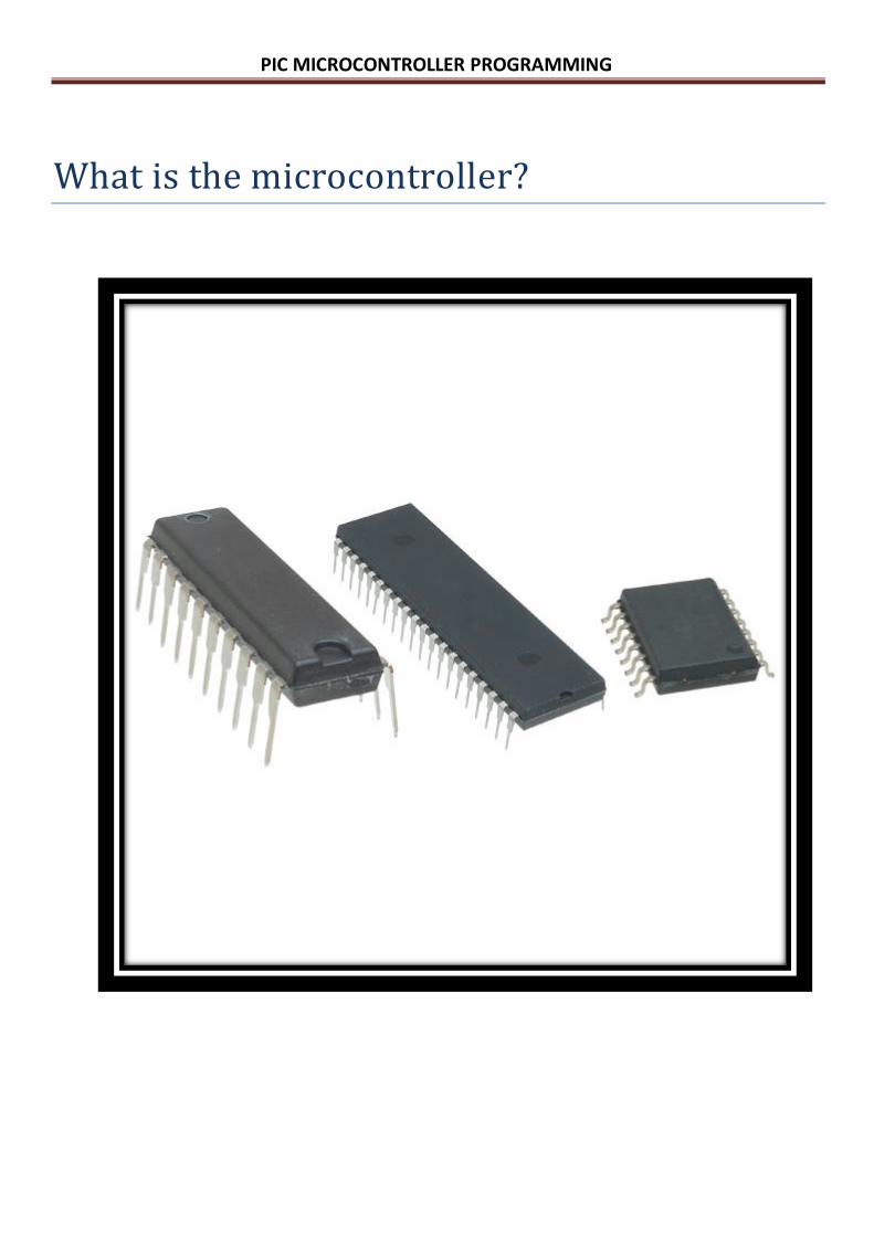
Microcontroller (μC) Vs microprocessor (μP).
Figure below shows the internal architecture of a typical µC system, and its equivalent
µP system, note that in the µC side, all devices are packaged in the same chip, in contrast of
µP system that each block is considered a stand-alone device.

PIC MICROCONTROLLER PROGRAMMING
PIC16 identification: PIC is generally assumed to mean Peripheral Interface Controller, it comes with a
variety of families; PIC10 and PIC12 (Base-line), PIC16 (Mid-range), PIC17 (High-end),
PIC18 (enhancement), Finally PIC24 and dsPIC. Here we will deeply look at PIC16
family. PIC16F84A is our interest MCU in this family.
PIC16F877A: Is a 40 pin chip, operating at a frequency up to 20MHz, it has five I/O ports
A(6),B(8),C(8),D(8),E(3) mapping to 33 pins, the following points highlight the
most important features:
1- 8Kbx 14 words Flash Program memory space.
2- 368 x 8 Bytes of DATA Memory (RAM).
3- 256 x 8 Bytes of EEPROM DATA Memory.
4- Five I/O PORTS.
5- Wide operating frequency DC-20MHz.
6- Wide operating voltage 2.0v – 5.5v.
7- Three timers with different capabilities. 8- Two Capture\Compare\PWM modules (CCP). 9- 10,000 erase/write cycles Enhanced FLASH Program memory typical.
10- 10,000,000 typical erase/write cycles EEPROM Data memory typical.
11- EEPROM Data Retention > 40 years.
12- 15 kinds of interrupts. 13- RS-232, I2C, and SPI interfaces (USART, MSSP). 14- current sink/source :
- 25 mA sink max. per pin.
- 25 mA source max. per pin.

PIC MICROCONTROLLER PROGRAMMING
MEMORY ORGANIZATION: There are two memory blocks in the PIC16F877A.These are the program memory and the data memory. Each block has its own bus, so that access to each block can occur during the same oscillator cycle.
Program memory:
The PIC16F877A has a 13-bit program counter capable of addressing a 8K x 14
program memory space. The RESET vector is at 0000h and the interrupt vector is at
0004h .
Program Counter (PC): is CPU register where adresses of instructions are
stored.every time that the CPU looks for an instruction in the memory,the PC is
increased,pointing to the following instruction.in an instant of time the PC
contains the adress of the instruction that will be excuted next.
PIC MICROCONTROLLER PROGRAMMING
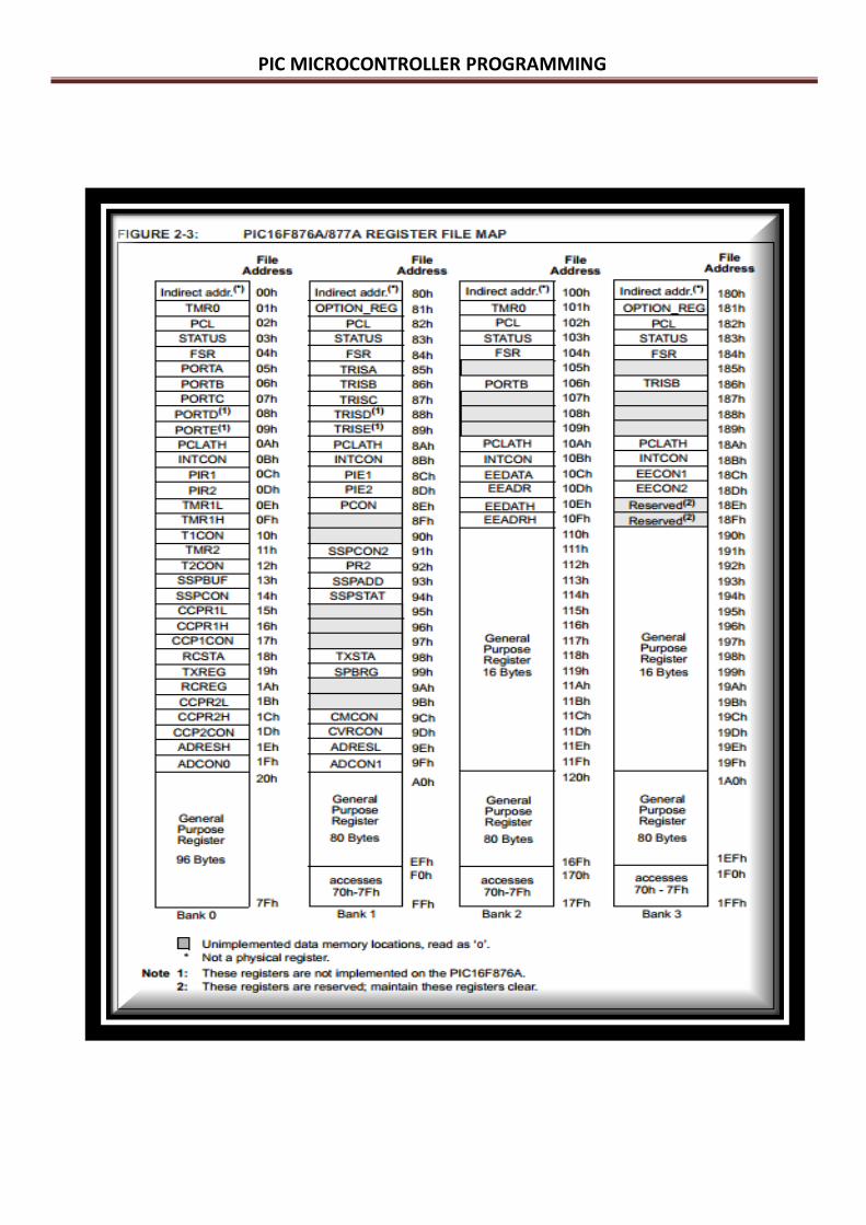
Data Memory(RAM):
Data Memory is devided into four pages called
Banks(Bank0,Bank1,Bank2,Bank3).
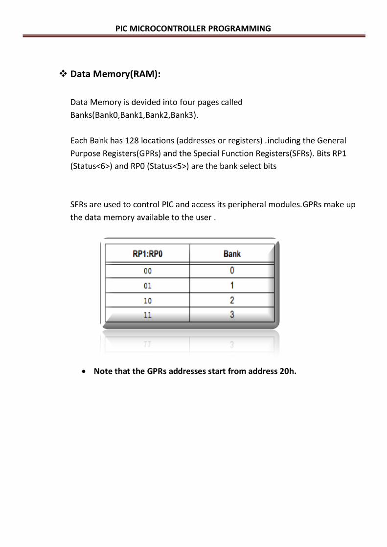
Each Bank has 128 locations (addresses or registers) .including the General
Purpose Registers(GPRs) and the Special Function Registers(SFRs). Bits RP1
(Status<6>) and RP0 (Status<5>) are the bank select bits
SFRs are used to control PIC and access its peripheral modules.GPRs make up
the data memory available to the user .
Note that the GPRs addresses start from address 20h.
PIC MICROCONTROLLER PROGRAMMING
PIC MICROCONTROLLER PROGRAMMING
Program memory Data memory EEPROM
Data bus 14 bit 8 bit 8 bit
Address bus 13 bit 7 bit 8 bit
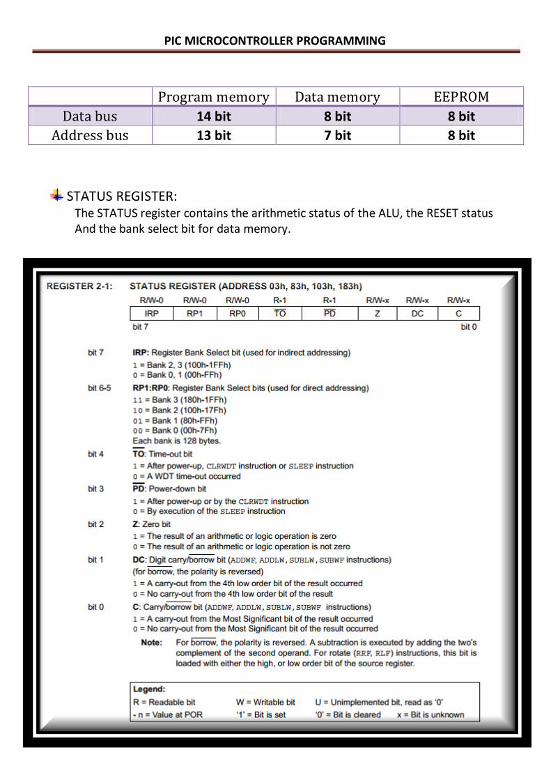
STATUS REGISTER: The STATUS register contains the arithmetic status of the ALU, the RESET status And the bank select bit for data memory.
PIC MICROCONTROLLER PROGRAMMING
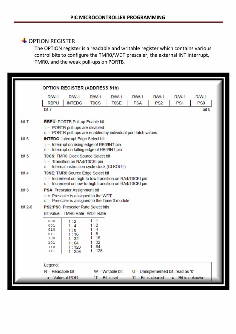
OPTION REGISTER The OPTION register is a readable and writable register which contains various control bits to configure the TMR0/WDT prescaler, the external INT interrupt, TMR0, and the weak pull-ups on PORTB.

PIC MICROCONTROLLER PROGRAMMING
PINOUT:
Pic16F877A has 40 pins:
33 as i/o pins.
7 pins for biase ,oscillator and reset .
MCLR# (reset pin): pin # 1 ,this pin used to
manually reset the program execution when
it goes low (logicaly zero).
Connection:this pin is active low so it is usually connected to 5 Volt
(Vcc/Vdd) through a resistor (typical 10KΩ) to prevent any unwanted reset
during program execution.
PIC MICROCONTROLLER PROGRAMMING
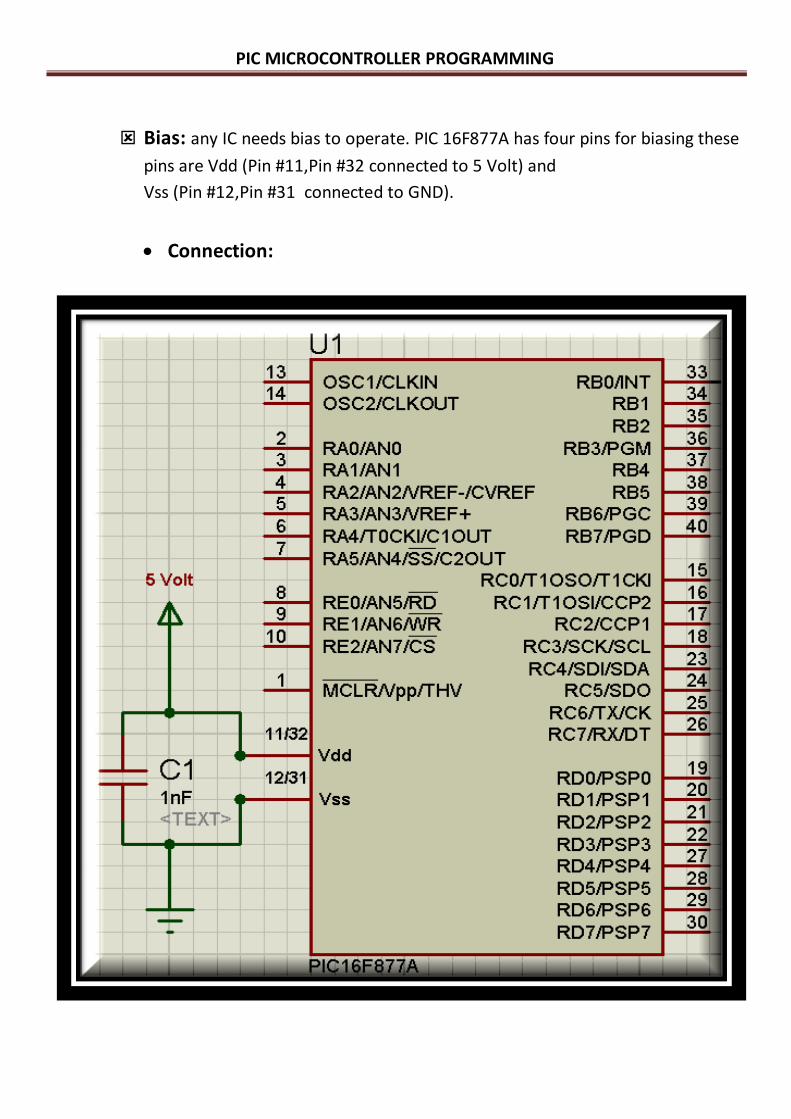
Bias: any IC needs bias to operate. PIC 16F877A has four pins for biasing these
pins are Vdd (Pin #11,Pin #32 connected to 5 Volt) and
Vss (Pin #12,Pin #31 connected to GND).
Connection:

PIC MICROCONTROLLER PROGRAMMING
Oscillator: the µC needs oscillator to generate the signal necessary to
synchronize all internal operation.
PIC16F877A has two pins for oscillator these pins are pin #13
(OSC1/CLKIN) and pin #14 (OSC2/CLKOUT).
Connection:
The main oscillator in PIC Microcontroller can be internal or External
clock.
Internal Oscillator/Clock: Some of microcontrollers have an internal RC
oscillator.
- frequency up to 4 MHz.
- error 1.5%.
- 12xxx,10xxx,some of 16xxx and 18xxx series.
PIC MICROCONTROLLER PROGRAMMING
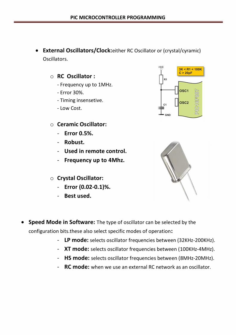
External Oscillators/Clock:either RC Oscillator or (crystal/cyramic)
Oscillators.
o RC Oscillator :
- Frequency up to 1MHz.
- Error 30%.
- Timing insensetive.
- Low Cost.
o Ceramic Oscillator:
- Error 0.5%.
- Robust.
- Used in remote control.
- Frequency up to 4Mhz.
o Crystal Oscillator:
- Error (0.02-0.1)%.
- Best used.
Speed Mode in Software: The type of oscillator can be selected by the
configuration bits.these also select specific modes of operation:
- LP mode: selects oscillator frequencies between (32KHz-200KHz).
- XT mode: selects oscillator frequencies between (100KHz-4MHz).
- HS mode: selects oscillator frequencies between (8MHz-20MHz).
- RC mode: when we use an external RC network as an oscillator.
PIC MICROCONTROLLER PROGRAMMING
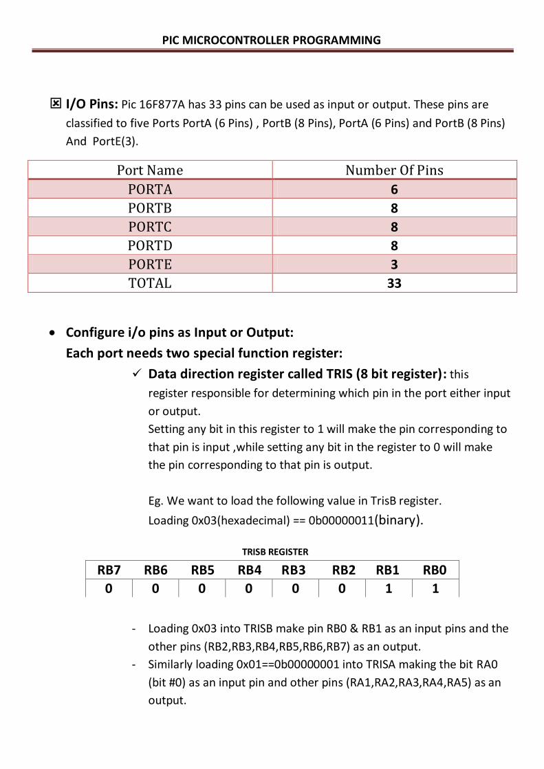
I/O Pins: Pic 16F877A has 33 pins can be used as input or output. These pins are
classified to five Ports PortA (6 Pins) , PortB (8 Pins), PortA (6 Pins) and PortB (8 Pins)
And PortE(3).
Port Name Number Of Pins
PORTA 6
PORTB 8
PORTC 8
PORTD 8
PORTE 3
TOTAL 33
Configure i/o pins as Input or Output:
Each port needs two special function register:
Data direction register called TRIS (8 bit register): this
register responsible for determining which pin in the port either input
or output.
Setting any bit in this register to 1 will make the pin corresponding to
that pin is input ,while setting any bit in the register to 0 will make
the pin corresponding to that pin is output.
Eg. We want to load the following value in TrisB register.
Loading 0x03(hexadecimal) == 0b00000011(binary).
- Loading 0x03 into TRISB make pin RB0 & RB1 as an input pins and the
other pins (RB2,RB3,RB4,RB5,RB6,RB7) as an output.
- Similarly loading 0x01==0b00000001 into TRISA making the bit RA0
(bit #0) as an input pin and other pins (RA1,RA2,RA3,RA4,RA5) as an
output.
RB7 RB6 RB5 RB4 RB3 RB2 RB1 RB0
0 0 0 0 0 0 1 1
TRISB REGISTER

PIC MICROCONTROLLER PROGRAMMING
RA5 RA4 RA3 RA2 RA1 RA0
0 0 0 0 0 1
Data Register Called Port (8 bit register): this register responsible for writing to
the output pins or reading from input pins.
Configuration Bits: these bits allow the programmer to specify certain
aspects of microcontroller to better fit the intended application.
- These bits must be selected at the beginning of the program.
- These bits can't be changed during programming.
- These bits like fuses.
- These bits are responsible for specifying :
i. Oscillator mode.
ii. Reset parameter (watchdog timer on or off, brown out).
iii. Program memory protection.
iv. Protection of EEPROM data.
v. Power mode (3v or 5v).
Selecting the configuration bits in software:
The configuration bits must be selected at the beginning of the program by writing
the following statement
__CONFIG _XT_OSC &_LVP_OFF &_WDT_OFF &_PWRTE_ON &_CP_OFF
TRISA REGISTER
PIC MICROCONTROLLER PROGRAMMING
References:
1. Microcontroller fundamentals and applications with PIC, Fernando E.Valdes.
2. PIC MICROCONTROLLER,Ahmed Ihmeid.
3. PIC 16F877A datasheet ,microchip.

PIC MICROCONTROLLER PROGRAMMING
GOOD LUCK
ENG AHMED AKOUR