PIC Micro Controller - Wikipedia, The Free Encyclopedia
17
2/3/12 PIC microcontroller - Wikipedia, the free enc\clopedia 1/17 en.wikipedia.org/wiki/PIC_microcontroller PIC micUoconWUolleUV in DIP and QFN packageV 16-biW 28-pin PDIP PIC24 micUoconWUolleU ne[W Wo a meWUic UXleU PIC micUoconWUolleU FUom Wikipedia, Whe fUee enc\clopedia PIC iV a famil\ of modified HaUYaUd aUchiWecWXUe micUoconWUolleUV made b\ MicUochip Technolog\, deUiYed fUom Whe PIC1650 [1][2][3] oUiginall\ deYeloped b\ GeneUal InVWUXmenW'V MicUoelecWUonicV DiYiVion. The name PIC iniWiall\ UefeUUed Wo " PeUipheUal InWeUface ConWUolleU ". [4][5] PICV aUe popXlaU ZiWh boWh indXVWUial deYelopeUV and hobb\iVWV alike dXe Wo WheiU loZ coVW, Zide aYailabiliW\, laUge XVeU baVe, e[WenViYe collecWion of applicaWion noWeV, aYailabiliW\ of loZ coVW oU fUee deYelopmenW WoolV, and VeUial pUogUamming (and Ue-pUogUamming ZiWh flaVh memoU\) capabiliW\. MicUochip annoXnced on SepWembeU 2011 Whe VhipmenW of iWV Wen billionWh PIC pUoceVVoU. [6] ConWenWV 1 CoUe aUchiWecWXUe 1.1 DaWa Vpace (RAM) 1.2 Code Vpace 1.3 WoUd Vi]e 1.4 SWackV 1.5 InVWUXcWion VeW 1.6 PeUfoUmance 1.7 AdYanWageV 1.8 LimiWaWionV 1.9 CompileU deYelopmenW 2 Famil\ coUe aUchiWecWXUal diffeUenceV 2.1 BaVeline coUe deYiceV 2.2 Mid-Uange coUe deYiceV 2.3 Enhanced Mid-Uange coUe deYiceV 2.4 PIC17 high end coUe deYiceV 2.5 PIC18 high end coUe deYiceV 2.6 PIC24 and dVPIC 16-biW micUoconWUolleUV 2.7 PIC32 32-biW micUoconWUolleUV 3 DeYice YaUianWV and haUdZaUe feaWXUeV 3.1 VaUianW V 3.2 TUendV 4 HiVWoU\ 5 PIC cloneV 6 DeYelopmenW WoolV 7 DeYice pUogUammeUV 8 DebXgging
Transcript of PIC Micro Controller - Wikipedia, The Free Encyclopedia
2/3/12 PIC microcontroller - Wikipedia, the free encyclopedia
1/17en.wikipedia.org/wiki/PIC_microcontroller
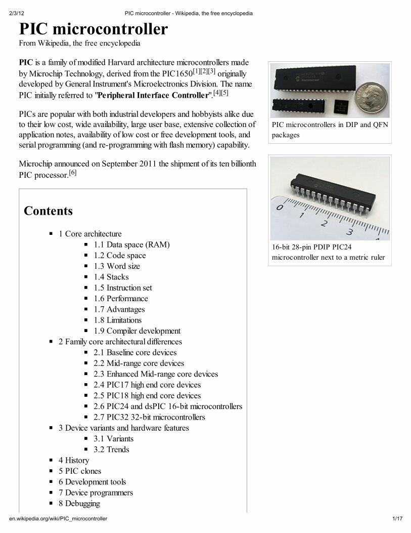
PIC microcontrollers in DIP and QFN
packages
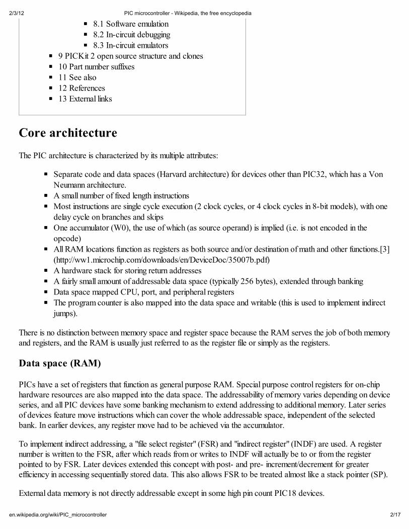
16-bit 28-pin PDIP PIC24
microcontroller next to a metric ruler
PIC microcontrollerFrom Wikipedia, the free encyclopedia
PIC is a family of modified Harvard architecture microcontrollers made
by Microchip Technology, derived from the PIC1650[1][2][3] originallydeveloped by General Instrument's Microelectronics Division. The name
PIC initially referred to "Peripheral Interface Controller".[4][5]
PICs are popular with both industrial developers and hobbyists alike dueto their low cost, wide availability, large user base, extensive collection ofapplication notes, availability of low cost or free development tools, andserial programming (and re-programming with flash memory) capability.
Microchip announced on September 2011 the shipment of its ten billionth
PIC processor.[6]
Contents
1 Core architecture
1.1 Data space (RAM)1.2 Code space
1.3 Word size
1.4 Stacks
1.5 Instruction set
1.6 Performance1.7 Advantages
1.8 Limitations
1.9 Compiler development
2 Family core architectural differences
2.1 Baseline core devices
2.2 Mid-range core devices
2.3 Enhanced Mid-range core devices
2.4 PIC17 high end core devices
2.5 PIC18 high end core devices2.6 PIC24 and dsPIC 16-bit microcontrollers
2.7 PIC32 32-bit microcontrollers
3 Device variants and hardware features
3.1 Variants
3.2 Trends
4 History
5 PIC clones
6 Development tools
7 Device programmers
8 Debugging
2/3/12 PIC microcontroller - Wikipedia, the free encyclopedia
2/17en.wikipedia.org/wiki/PIC_microcontroller
8.1 Software emulation
8.2 In-circuit debugging
8.3 In-circuit emulators
9 PICKit 2 open source structure and clones
10 Part number suffixes
11 See also12 References
13 External links
Core architecture
The PIC architecture is characterized by its multiple attributes:
Separate code and data spaces (Harvard architecture) for devices other than PIC32, which has a Von
Neumann architecture.A small number of fixed length instructions
Most instructions are single cycle execution (2 clock cycles, or 4 clock cycles in 8-bit models), with one
delay cycle on branches and skipsOne accumulator (W0), the use of which (as source operand) is implied (i.e. is not encoded in the
opcode)All RAM locations function as registers as both source and/or destination of math and other functions.[3](http://ww1.microchip.com/downloads/en/DeviceDoc/35007b.pdf)
A hardware stack for storing return addressesA fairly small amount of addressable data space (typically 256 bytes), extended through banking
Data space mapped CPU, port, and peripheral registersThe program counter is also mapped into the data space and writable (this is used to implement indirect
jumps).
There is no distinction between memory space and register space because the RAM serves the job of both memoryand registers, and the RAM is usually just referred to as the register file or simply as the registers.
Data space (RAM)
PICs have a set of registers that function as general purpose RAM. Special purpose control registers for on-chiphardware resources are also mapped into the data space. The addressability of memory varies depending on deviceseries, and all PIC devices have some banking mechanism to extend addressing to additional memory. Later seriesof devices feature move instructions which can cover the whole addressable space, independent of the selectedbank. In earlier devices, any register move had to be achieved via the accumulator.
To implement indirect addressing, a "file select register" (FSR) and "indirect register" (INDF) are used. A registernumber is written to the FSR, after which reads from or writes to INDF will actually be to or from the registerpointed to by FSR. Later devices extended this concept with post- and pre- increment/decrement for greaterefficiency in accessing sequentially stored data. This also allows FSR to be treated almost like a stack pointer (SP).
External data memory is not directly addressable except in some high pin count PIC18 devices.

2/3/12 PIC microcontroller - Wikipedia, the free encyclopedia
3/17en.wikipedia.org/wiki/PIC_microcontroller
Code space
The code space is generally implemented as ROM, EPROM or flash ROM. In general, external code memory isnot directly addressable due to the lack of an external memory interface. The exceptions are PIC17 and select high
pin count PIC18 devices.[7]
Word size
All PICs handle (and address) data in 8-bit chunks. However, the unit of addressability of the code space is notgenerally the same as the data space. For example, PICs in the baseline and mid-range families have programmemory addressable in the same wordsize as the instruction width, i.e. 12 or 14 bits respectively. In contrast, in thePIC18 series, the program memory is addressed in 8-bit increments (bytes), which differs from the instruction widthof 16 bits.
In order to be clear, the program memory capacity is usually stated in number of (single word) instructions, ratherthan in bytes.
Stacks
PICs have a hardware call stack, which is used to save return addresses. The hardware stack is not softwareaccessible on earlier devices, but this changed with the 18 series devices.
Hardware support for a general purpose parameter stack was lacking in early series, but this greatly improved inthe 18 series, making the 18 series architecture more friendly to high level language compilers.
Instruction set
A PIC's instructions vary from about 35 instructions for the low-end PICs to over 80 instructions for the high-endPICs. The instruction set includes instructions to perform a variety of operations on registers directly, theaccumulator and a literal constant or the accumulator and a register, as well as for conditional execution, andprogram branching.
Some operations, such as bit setting and testing, can be performed on any numbered register, but bi-operandarithmetic operations always involve W (the accumulator), writing the result back to either W or the other operandregister. To load a constant, it is necessary to load it into W before it can be moved into another register. On theolder cores, all register moves needed to pass through W, but this changed on the "high end" cores.
PIC cores have skip instructions which are used for conditional execution and branching. The skip instructions are'skip if bit set' and 'skip if bit not set'. Because cores before PIC18 had only unconditional branch instructions,conditional jumps are implemented by a conditional skip (with the opposite condition) followed by an unconditionalbranch. Skips are also of utility for conditional execution of any immediate single following instruction.
The 18 series implemented shadow registers which save several important registers during an interrupt, providinghardware support for automatically saving processor state when servicing interrupts.
In general, PIC instructions fall into 5 classes:
1. Operation on working register (WREG) with 8-bit immediate ("literal") operand. E.g. P R Y O Z (move literal to

2/3/12 PIC microcontroller - Wikipedia, the free encyclopedia
4/17en.wikipedia.org/wiki/PIC_microcontroller
WREG), D Q G O Z (AND literal with WREG). One instruction peculiar to the PIC is U H W O Z , load immediate
into WREG and return, which is used with computed branches to produce lookup tables.
2. Operation with WREG and indexed register. The result can be written to either the Working register (e.g.D G G Z I � r e g � Z ). or the selected register (e.g. D G G Z I � r e g � I ).
3. Bit operations. These take a register number and a bit number, and perform one of 4 actions: set or clear a
bit, and test and skip on set/clear. The latter are used to perform conditional branches. The usual ALU status
flags are available in a numbered register so operations such as "branch on carry clear" are possible.4. Control transfers. Other than the skip instructions previously mentioned, there are only two: J R W R and F D O O .
5. A few miscellaneous zero-operand instructions, such as return from subroutine, and V O H H S to enter low-
power mode.
Performance
The architectural decisions are directed at the maximization of speed-to-cost ratio. The PIC architecture was
among the first scalar CPU designs,[citation needed] and is still among the simplest and cheapest. The Harvardarchitecture—in which instructions and data come from separate sources—simplifies timing and microcircuit designgreatly, and this benefits clock speed, price, and power consumption.
The PIC instruction set is suited to implementation of fast lookup tables in the program space. Such lookups takeone instruction and two instruction cycles. Many functions can be modeled in this way. Optimization is facilitated bythe relatively large program space of the PIC (e.g. 4096 × 14-bit words on the 16F690) and by the design of theinstruction set, which allows for embedded constants. For example, a branch instruction's target may be indexed byW, and execute a "RETLW" which does as it is named - return with literal in W.
Interrupt latency is constant at three instruction cycles. External interrupts have to be synchronized with the fourclock instruction cycle, otherwise there can be a one instruction cycle jitter. Internal interrupts are alreadysynchronized. The constant interrupt latency allows PICs to achieve interrupt driven low jitter timing sequences. Anexample of this is a video sync pulse generator. This is no longer true in the newest PIC models, because they havea synchronous interrupt latency of three or four cycles.
Advantages
The PIC architectures have these advantages:
Small instruction set to learnRISC architecture
Built in oscillator with selectable speeds
Easy entry level, in circuit programming plus in circuit debugging PICKit units available from
Microchip.com for less than $50Inexpensive microcontrollers
Wide range of interfaces including I²C, SPI, USB, USART, A/D, programmable comparators, PWM,
LIN, CAN, PSP, and Ethernet[8]
Limitations
The PIC architectures have these limitations:
2/3/12 PIC microcontroller - Wikipedia, the free encyclopedia
5/17en.wikipedia.org/wiki/PIC_microcontroller
One accumulator
Register-bank switching is required to access the entire RAM of many devices
Operations and registers are not orthogonal; some instructions can address RAM and/or immediateconstants, while others can only use the accumulator
The following stack limitations have been addressed in the PIC18 series, but still apply to earlier cores:
The hardware call stack is not addressable, so preemptive task switching cannot be implemented
Software-implemented stacks are not efficient, so it is difficult to generate reentrant code and supportlocal variables
With paged program memory, there are two page sizes to worry about: one for CALL and GOTO and another forcomputed GOTO (typically used for table lookups). For example, on PIC16, CALL and GOTO have 11 bits ofaddressing, so the page size is 2048 instruction words. For computed GOTOs, where you add to PCL, the pagesize is 256 instruction words. In both cases, the upper address bits are provided by the PCLATH register. Thisregister must be changed every time control transfers between pages. PCLATH must also be preserved by any
interrupt handler.[9]
Compiler development
While several commercial compilers are available, in 2008, Microchip released their own C compilers, C18 andC30, for the line of 18F 24F and 30/33F processors.
The easy to learn RISC instruction set of the PIC assembly language code can make the overall flow difficult tocomprehend. Judicious use of simple macros can increase the readability of PIC assembly language. For example,the original Parallax PIC assembler ("SPASM") has macros which hide W and make the PIC look like a two-address machine. It has macro instructions like "P R Y � E � � D " (move the data from address a to address b) and "D G G
E � � D " (add data from address a to data in address b). It also hides the skip instructions by providing three operand
branch macro instructions such as "F M Q H � D � � E � � G H V W " (compare a with b and jump to dest if they are not equal).
Family core architectural differences
Baseline core devices
These devices feature a 12-bit wide code memory, a 32-byte register file, and a tiny two level deep call stack.They are represented by the PIC10 series, as well as by some PIC12 and PIC16 devices. Baseline devices areavailable in 6-pin to 40-pin packages.
Generally the first 7 to 9 bytes of the register file are special-purpose registers, and the remaining bytes are generalpurpose RAM. Pointers are implemented using a register pair: after writing an address to the FSR (file selectregister), the INDF (indirect f) register becomes an alias for the addressed register. If banked RAM isimplemented, the bank number is selected by the high 3 bits of the FSR. This affects register numbers 16–31;registers 0–15 are global and not affected by the bank select bits.
Because of the very limited register space (5 bits), 4 rarely-read registers were not assigned addresses, but writtenby special instructions (2 3 7 , 2 1 and 7 5, 6 ).
2/3/12 PIC microcontroller - Wikipedia, the free encyclopedia
6/17en.wikipedia.org/wiki/PIC_microcontroller
The ROM address space is 512 words (12 bits each), which may be extended to 2048 words by banking. & $ / /
and * 2 7 2 instructions specify the low 9 bits of the new code location; additional high-order bits are taken from the
status register. Note that a CALL instruction only includes 8 bits of address, and may only specify addresses in thefirst half of each 512-word page.
Lookup tables are implemented using a computed * 2 7 2 (assignment to PCL register) into a table of 5( 7 / :
instructions.
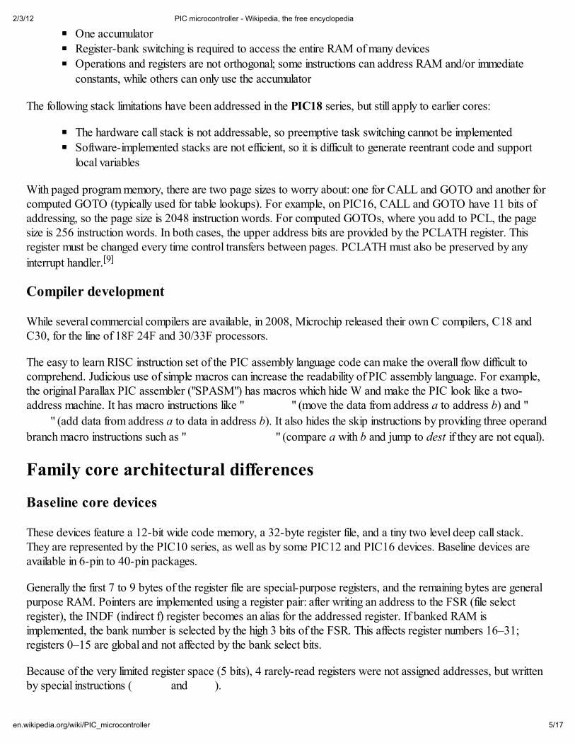
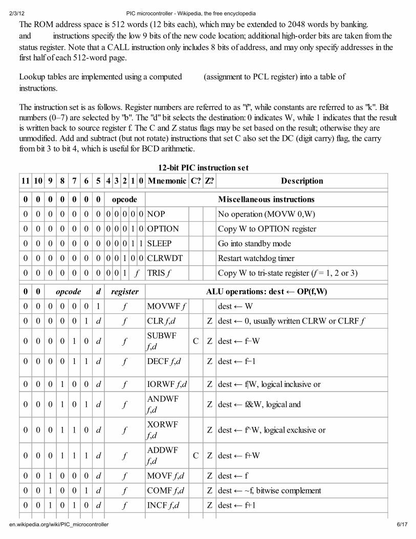
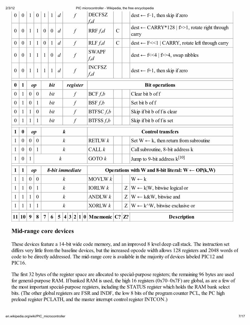
The instruction set is as follows. Register numbers are referred to as "f", while constants are referred to as "k". Bitnumbers (0–7) are selected by "b". The "d" bit selects the destination: 0 indicates W, while 1 indicates that the resultis written back to source register f. The C and Z status flags may be set based on the result; otherwise they areunmodified. Add and subtract (but not rotate) instructions that set C also set the DC (digit carry) flag, the carryfrom bit 3 to bit 4, which is useful for BCD arithmetic.
12-bit PIC instruction set
11 10 9 8 7 6 5 4 3 2 1 0 Mnemonic C? Z? Description
0 0 0 0 0 0 0 opcode Miscellaneous instructions
0 0 0 0 0 0 0 0 0 0 0 0 NOP No operation (MOVW 0,W)
0 0 0 0 0 0 0 0 0 0 1 0 OPTION Copy W to OPTION register
0 0 0 0 0 0 0 0 0 0 1 1 SLEEP Go into standby mode
0 0 0 0 0 0 0 0 0 1 0 0 CLRWDT Restart watchdog timer
0 0 0 0 0 0 0 0 0 1 f TRIS f Copy W to tri-state register (f = 1, 2 or 3)
0 0 opcode d register ALU operations: dest ← OP(f,W)
0 0 0 0 0 0 1 f MOVWF f dest ← W
0 0 0 0 0 1 d f CLR f,d Z dest ← 0, usually written CLRW or CLRF f
0 0 0 0 1 0 d fSUBWF
f,dC Z dest ← f−W
0 0 0 0 1 1 d f DECF f,d Z dest ← f−1
0 0 0 1 0 0 d f IORWF f,d Z dest ← f|W, logical inclusive or
0 0 0 1 0 1 d fANDWFf,d
Z dest ← f&W, logical and
0 0 0 1 1 0 d fXORWF
f,dZ dest ← f̂ W, logical exclusive or
0 0 0 1 1 1 d fADDWF
f,dC Z dest ← f+W
0 0 1 0 0 0 d f MOVF f,d Z dest ← f
0 0 1 0 0 1 d f COMF f,d Z dest ← ~f, bitwise complement
0 0 1 0 1 0 d f INCF f,d Z dest ← f+1
2/3/12 PIC microcontroller - Wikipedia, the free encyclopedia
7/17en.wikipedia.org/wiki/PIC_microcontroller
0 0 1 0 1 1 d f DECFSZf,d
dest ← f−1, then skip if zero
0 0 1 1 0 0 d f RRF f,d Cdest ← CARRY*128 | f>>1, rotate right through
carry
0 0 1 1 0 1 d f RLF f,d C dest ← F<<1 | CARRY, rotate left through carry
0 0 1 1 1 0 d fSWAPF
f,ddest ← f<<4 | f>>4, swap nibbles
0 0 1 1 1 1 d fINCFSZ
f,ddest ← f+1, then skip if zero
0 1 op bit register Bit operations
0 1 0 0 bit f BCF f,b Clear bit b of f
0 1 0 1 bit f BSF f,b Set bit b of f
0 1 1 0 bit f BTFSC f,b Skip if bit b of f is clear
0 1 1 1 bit f BTFSS f,b Skip if bit b of f is set
1 0 op k Control transfers
1 0 0 0 k RETLW k Set W ← k, then return from subroutine
1 0 0 1 k CALL k Call subroutine, 8-bit address k
1 0 1 k GOTO k Jump to 9-bit address k[10]
1 1 op 8-bit immediate Operations with W and 8-bit literal: W ← OP(k,W)
1 1 0 0 k MOVLW k W ← k
1 1 0 1 k IORLW k Z W ← k|W, bitwise logical or
1 1 1 0 k ANDLW k Z W ← k&W, bitwise and
1 1 1 1 k XORLW k Z W ← k^W, bitwise exclusive or
11 10 9 8 7 6 5 4 3 2 1 0 Mnemonic C? Z? Description
Mid-range core devices
These devices feature a 14-bit wide code memory, and an improved 8 level deep call stack. The instruction setdiffers very little from the baseline devices, but the increased opcode width allows 128 registers and 2048 words ofcode to be directly addressed. The mid-range core is available in the majority of devices labeled PIC12 andPIC16.
The first 32 bytes of the register space are allocated to special-purpose registers; the remaining 96 bytes are usedfor general-purpose RAM. If banked RAM is used, the high 16 registers (0x70–0x7F) are global, as are a few ofthe most important special-purpose registers, including the STATUS register which holds the RAM bank selectbits. (The other global registers are FSR and INDF, the low 8 bits of the program counter PCL, the PC highpreload register PCLATH, and the master interrupt control register INTCON.)
2/3/12 PIC microcontroller - Wikipedia, the free encyclopedia
8/17en.wikipedia.org/wiki/PIC_microcontroller
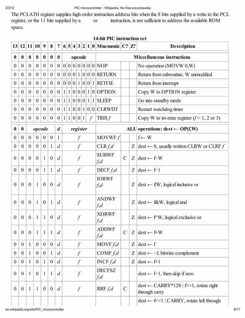
The PCLATH register supplies high-order instruction address bits when the 8 bits supplied by a write to the PCLregister, or the 11 bits supplied by a * 2 7 2 or & $ / / instruction, is not sufficient to address the available ROM
space.
14-bit PIC instruction set
13 12 11 10 9 8 7 6 5 4 3 2 1 0 Mnemonic C? Z? Description
0 0 0 0 0 0 0 opcode Miscellaneous instructions
0 0 0 0 0 0 0 0 0 0 0 0 0 0 NOP No operation (MOVW 0,W)
0 0 0 0 0 0 0 0 0 0 1 0 0 0 RETURN Return from subroutine, W unmodified
0 0 0 0 0 0 0 0 0 0 1 0 0 1 RETFIE Return from interrupt
0 0 0 0 0 0 0 1 1 0 0 0 1 0 OPTION Copy W to OPTION register
0 0 0 0 0 0 0 1 1 0 0 0 1 1 SLEEP Go into standby mode
0 0 0 0 0 0 0 1 1 0 0 1 0 0 CLRWDT Restart watchdog timer
0 0 0 0 0 0 0 1 1 0 0 1 f TRIS f Copy W to tri-state register (f = 1, 2 or 3)
0 0 opcode d register ALU operations: dest ← OP(f,W)
0 0 0 0 0 0 1 f MOVWF f f ← W
0 0 0 0 0 1 d f CLR f,d Z dest ← 0, usually written CLRW or CLRF f
0 0 0 0 1 0 d fSUBWF
f,dC Z dest ← f−W
0 0 0 0 1 1 d f DECF f,d Z dest ← f−1
0 0 0 1 0 0 d fIORWF
f,d Z dest ← f|W, logical inclusive or
0 0 0 1 0 1 d fANDWF
f,dZ dest ← f&W, logical and
0 0 0 1 1 0 d fXORWFf,d
Z dest ← f̂ W, logical exclusive or
0 0 0 1 1 1 d fADDWF
f,dC Z dest ← f+W
0 0 1 0 0 0 d f MOVF f,d Z dest ← f
0 0 1 0 0 1 d f COMF f,d Z dest ← ~f, bitwise complement
0 0 1 0 1 0 d f INCF f,d Z dest ← f+1
0 0 1 0 1 1 d fDECFSZ
f,ddest ← f−1, then skip if zero
0 0 1 1 0 0 d f RRF f,d Cdest ← CARRY*128 | f>>1, rotate rightthrough carry
dest ← f<<1 | CARRY, rotate left through
2/3/12 PIC microcontroller - Wikipedia, the free encyclopedia
9/17en.wikipedia.org/wiki/PIC_microcontroller
0 0 1 1 0 1 d f RLF f,d C carry
0 0 1 1 1 0 d fSWAPF
f,ddest ← f<<4 | f>>4, swap nibbles
0 0 1 1 1 1 d fINCFSZ
f,ddest ← f+1, then skip if zero
0 1 op bit register Bit operations
0 1 0 0 bit f BCF f,b Clear bit b of f
0 1 0 1 bit f BSF f,b Set bit b of f
0 1 1 0 bit f BTFSC f,b Skip if bit b of f is clear
0 1 1 1 bit f BTFSS f,b Skip if bit b of f is set
1 0 op k Control transfers
1 0 0 k CALL k Call subroutine
1 0 1 k GOTO k Jump to address k
1 1 op 8-bit immediate Operations with W and 8-bit literal: W ← OP(k,W)
1 1 0 0 x x kMOVLW
kW ← k
1 1 0 1 x x k RETLW k W ← k, then return from subroutine
1 1 1 0 0 0 k IORLW k Z W ← k|W, bitwise logical or
1 1 1 0 0 1 k ANDLW k Z W ← k&W, bitwise and
1 1 1 0 1 0 k XORLW k Z W ← k^W, bitwise exclusive or
1 1 1 0 1 1 k (reserved)
1 1 1 1 0 x k SUBLW k C Z W ← k−W, subtract
1 1 1 1 1 x k ADDLW k C Z W ← k+W, add
13 12 11 10 9 8 7 6 5 4 3 2 1 0 Mnemonic C? Z? Description
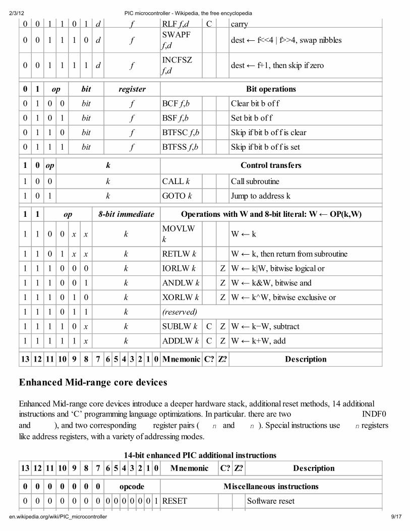
Enhanced Mid-range core devices
Enhanced Mid-range core devices introduce a deeper hardware stack, additional reset methods, 14 additionalinstructions and ‘C’ programming language optimizations. In particular. there are two , 1 ' ) � U H J L V W H U V � � INDF0
and , 1 ' ) � ), and two corresponding ) 6 5 register pairs () 6 5Q / and ) 6 5Q + ). Special instructions use ) 6 5Q registers
like address registers, with a variety of addressing modes.
14-bit enhanced PIC additional instructions
13 12 11 10 9 8 7 6 5 4 3 2 1 0 Mnemonic C? Z? Description
0 0 0 0 0 0 0 opcode Miscellaneous instructions
0 0 0 0 0 0 0 0 0 0 0 0 0 1 RESET Software reset
2/3/12 PIC microcontroller - Wikipedia, the free encyclopedia
10/17en.wikipedia.org/wiki/PIC_microcontroller
0 0 0 0 0 0 0 0 0 0 1 0 1 0 CALLW Push PC, then jump to PCLATH:W
0 0 0 0 0 0 0 0 0 0 1 0 1 1 BRW PC ← PC + W, relative jump using W
0 0 0 0 0 0 0 0 0 1 0 n 0 0MOVIW
++FSRnZ Increment FSRn, then W ← INDFn
0 0 0 0 0 0 0 0 0 1 0 n 0 1MOVIW −−FSRn
Z Decrement FSRn, then W ← INDFn
0 0 0 0 0 0 0 0 0 1 0 n 1 0MOVIW
FSRn++Z W ← INDFn, then increment FSRn
0 0 0 0 0 0 0 0 0 1 0 n 1 1MOVIW
FSRn−−Z W ← INDFn, then decrement FSRn
0 0 0 0 0 0 0 0 0 1 1 n mMOVWI using
FSRnINDFn ← W, same modes as MOVIW
0 0 0 0 0 0 0 0 1 k MOVLB kBSR ← k, move literal to bank select
register
1 1 opcode d register ALU operations: dest ← OP(f,W)
1 1 0 1 0 1 d f LSLF f,d C Z dest ← f << 1, logical shift left
1 1 0 1 1 0 d f LSRF f,d C Z dest ← f >> 1, logical shift right
1 1 0 1 1 1 d f ASRF f,d C Z dest ← f >> 1, arithmetic shift right
1 1 1 0 1 1 d f SUBWFB f,d C Zdest ← f − W − 1 + C, subtract with
carry
1 1 1 1 0 1 d f ADDWFC f,d C Z dest ← f + W + C, add with carry
1 1 opcode k Operations with literal k
1 1 0 0 0 1 0 n kADDFSR
FSRn,k
FSRn ← FSRn + k, add 6-bit signed
offset
1 1 0 0 0 1 1 k MOVLP kPCLATH ← k, move 7-bit literal to PC
latch high
1 1 0 0 1 k BRA kPC ← PC + k, branch relative using 9-
bit signed offset
1 1 1 1 1 1 0 n kMOVIW
k[FSRn]Z W ← [FSRn+k], 6-bit signed offset
1 1 1 1 1 1 1 n kMOVWI
k[FSRn][FSRn+k] ← W, 6-bit signed offset
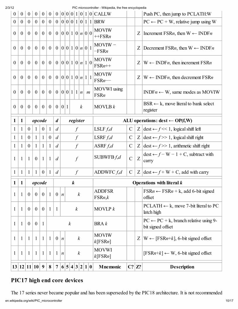
13 12 11 10 9 8 7 6 5 4 3 2 1 0 Mnemonic C? Z? Description
PIC17 high end core devices
The 17 series never became popular and has been superseded by the PIC18 architecture. It is not recommended

2/3/12 PIC microcontroller - Wikipedia, the free encyclopedia
11/17en.wikipedia.org/wiki/PIC_microcontroller
for new designs, and availability may be limited.
Improvements over earlier cores are 16-bit wide opcodes (allowing many new instructions), and a 16 level deepcall stack. PIC17 devices were produced in packages from 40 to 68 pins.
The 17 series introduced a number of important new features:
a memory mapped accumulatorread access to code memory (table reads)
direct register to register moves (prior cores needed to move registers through the accumulator)
an external program memory interface to expand the code space
an 8-bit × 8-bit hardware multiplier
a second indirect register pair
auto-increment/decrement addressing controlled by control bits in a status register (ALUSTA)
PIC18 high end core devices
Microchip introduced the PIC18 architecture in 2000. [4] (http://mdubuc.freeshell.org/Sdcc/) Unlike the 17 series,it has proven to be very popular, with a large number of device variants presently in manufacture. In contrast toearlier devices, which were more often than not programmed in assembly, C has become the predominantdevelopment language [5] (http://www.microchipc.com/sourcecode/) .
The 18 series inherits most of the features and instructions of the 17 series, while adding a number of important newfeatures:
much deeper call stack (31 levels deep)the call stack may be read and written
conditional branch instructions
indexed addressing mode (PLUSW)
extending the FSR registers to 12 bits, allowing them to linearly address the entire data address space
the addition of another FSR register (bringing the number up to 3)
The auto increment/decrement feature was improved by removing the control bits and adding four new indirectregisters per FSR. Depending on which indirect file register is being accessed it is possible to postdecrement,postincrement, or preincrement FSR; or form the effective address by adding W to FSR.
In more advanced PIC18 devices, an "extended mode" is available which makes the addressing even morefavorable to compiled code:
a new offset addressing mode; some addresses which were relative to the access bank are now
interpreted relative to the FSR2 register
the addition of several new instructions, notable for manipulating the FSR registers.
These changes were primarily aimed at improving the efficiency of a data stack implementation. If FSR2 is usedeither as the stack pointer or frame pointer, stack items may be easily indexed—allowing more efficient re-entrantcode. Microchip's MPLAB C18 C compiler chooses to use FSR2 as a frame pointer.
PIC24 and dsPIC 16-bit microcontrollers
2/3/12 PIC microcontroller - Wikipedia, the free encyclopedia
12/17en.wikipedia.org/wiki/PIC_microcontroller
In 2001, Microchip introduced the dsPIC series of chips,[11] which entered mass production in late 2004. They areMicrochip's first inherently 16-bit microcontrollers. PIC24 devices are designed as general purposemicrocontrollers. dsPIC devices include digital signal processing capabilities in addition.
Architecturally, although they share the PIC moniker, they are very different from the 8-bit PICs. The most notable
differences are:[12]
they feature a set of 16 working registers (W0-W15)
they fully support a stack in RAM, and do not have a hardware stackbank switching is not required to access RAM or special function registers
data stored in program memory can be accessed directly using a feature called Program Space Visibilityinterrupt sources may be assigned to distinct handlers using an interrupt vector table
Some features are:
hardware MAC (multiply–accumulate)barrel shiftingbit reversal
(16×16)-bit single-cycle multiplication and other DSP operationshardware divide assist (19 cycles for 16/32-bit divide)
hardware support for loop indexingDirect memory access
dsPICs can be programmed in C using Microchip's C30 compiler which is a variant of gcc.
PIC32 32-bit microcontrollers
In November 2007 Microchip introduced the new PIC32MX (http://www.microchip.com/stellent/idcplg?IdcService=SS_GET_PAGE&nodeId=2018&mcparam=en532888) family of 32-bit microcontrollers. The initialdevice line-up is based on the industry standard MIPS32 M4K Core[6](http://www.mips.com/products/processors/32-64-bit-cores/mips32-m4k/) . The device can be programmed usingthe Microchip MPLAB C Compiler for PIC32 MCUs (http://microchip.com/c32) , a variant of the GCC compiler.The first 18 models currently in production (PIC32MX3xx and PIC32MX4xx) are pin to pin compatible and sharethe same peripherals set with the PIC24FxxGA0xx family of (16-bit) devices allowing the use of common libraries,software and hardware tools.
The PIC32 architecture brings a number of new features to Microchip portfolio, including:
The highest execution speed 80 MIPS (120+[13] Dhrystone MIPS @ 80 MHz)The largest flash memory: 512 kByte
One instruction per clock cycle executionThe first cached processor
Allows execution from RAMFull Speed Host/Dual Role and OTG USB capabilities
Full JTAG and 2 wire programming and debuggingReal-time trace

2/3/12 PIC microcontroller - Wikipedia, the free encyclopedia
13/17en.wikipedia.org/wiki/PIC_microcontroller
Device variants and hardware features
PIC devices generally feature:
Sleep mode (power savings).Watchdog timer.Various crystal or RC oscillator configurations, or an external clock.
Variants
Within a series, there are still many device variants depending on what hardware resources the chip features.
General purpose I/O pins.
Internal clock oscillators.8/16/32 Bit Timers.
Internal EEPROM Memory.Synchronous/Asynchronous Serial Interface USART.MSSP Peripheral for I²C and SPI Communications.
Capture/Compare and PWM modules.Analog-to-digital converters (up to ~1.0 MHz).
USB, Ethernet, CAN interfacing support.External memory interface.
Integrated analog RF front ends (PIC16F639, and rfPIC).KEELOQ Rolling code encryption peripheral (encode/decode)And many more.
Trends
The first generation of PICs with EPROM storage are almost completely replaced by chips with Flash memory.Likewise, the original 12-bit instruction set of the PIC1650 and its direct descendants has been superseded by 14-bit and 16-bit instruction sets. Microchip still sells OTP (one-time-programmable) and windowed (UV-erasable)versions of some of its EPROM based PICs for legacy support or volume orders. The Microchip website listsPICs that are not electrically erasable as OTP despite the fact that UV erasable windowed versions of these chipscan be ordered..
History
The original PIC was built to be used with General Instrument's new 16-bit CPU, the CP1600. While generally agood CPU, the CP1600 had poor I/O performance, and the 8-bit PIC was developed in 1975 to improveperformance of the overall system by offloading I/O tasks from the CPU. The PIC used simple microcode stored inROM to perform its tasks, and although the term was not used at the time, it shares some common features withRISC designs.
In 1985, General Instrument spun off their microelectronics division and the new ownership cancelled almosteverything — which by this time was mostly out-of-date. The PIC, however, was upgraded with internal EPROMto produce a programmable channel controller and today a huge variety of PICs are available with various on-

2/3/12 PIC microcontroller - Wikipedia, the free encyclopedia
14/17en.wikipedia.org/wiki/PIC_microcontroller
Various older (EPROM) PIC
microcontrollers
A development board for low pin-
count MCU, from Microchip
board peripherals (serial communication modules, UARTs, motor control kernels, etc.) and program memory from256 words to 64k words and more (a "word" is one assembly language instruction, varying from 12, 14 or 16 bitsdepending on the specific PIC micro family).
PIC and PICmicro are registered trademarks of Microchip Technology. It is generally thought that PIC stands forPeripheral Interface Controller, although General Instruments' original acronym for the initial PIC1640 and
PIC1650 devices was "Programmable Interface Controller".[4] The acronym was quickly replaced with
"Programmable Intelligent Computer".[5]
The Microchip 16C84 (PIC16x84), introduced in 1993 , was the
first[citation needed] Microchip CPU with on-chip EEPROM memory.This electrically erasable memory made it cost less than CPUs thatrequired a quartz "erase window" for erasing EPROM.
PIC clones
Third party manufacturers make compatible products, for example theParallax SX
Development tools
Microchip provides a freeware IDE package called MPLAB, which includes an assembler, linker, softwaresimulator, and debugger. They also sell C compilers for the PIC18 and dsPIC which integrate cleanly withMPLAB. Free student versions of the C compilers are also available with all features. But for the free versions,
optimizations will be disabled after 60 days.[14]
Several third parties make C language compilers for PICs, many of which integrate to MPLAB and/or feature theirown IDE. A fully featured compiler for the PICBASIC language to program PIC microcontrollers is available frommeLabs, Inc.
Development tools are available for the PIC family under the GPL or other free software or open sources licenses.
Device programmers
Devices called "programmers" are traditionally used to get program codeinto the target PIC. Most PICs that Microchip currently sell feature ICSP(In Circuit Serial Programming) and/or LVP (Low Voltage Programming)capabilities, allowing the PIC to be programmed while it is sitting in thetarget circuit. ICSP programming is performed using two pins, clock anddata, while a high voltage (12V) is present on the Vpp/MCLR pin. Lowvoltage programming dispenses with the high voltage, but reservesexclusive use of an I/O pin and can therefore be disabled to recover thepin for other uses (once disabled it can only be re-enabled using highvoltage programming).
There are many programmers for PIC microcontrollers, ranging from theextremely simple designs which rely on ICSP to allow direct download of code from a host computer, to intelligent

2/3/12 PIC microcontroller - Wikipedia, the free encyclopedia
15/17en.wikipedia.org/wiki/PIC_microcontroller
Microchip PICSTART Plus
programmer
programmers that can verify the device at several supply voltages. Many of these complex programmers use a pre-programmed PIC themselves to send the programming commands to the PIC that is to be programmed. Theintelligent type of programmer is needed to program earlier PIC models (mostly EPROM type) which do notsupport in-circuit programming.
Many of the higher end flash based PICs can also self-program (write to their own program memory). Demoboards are available with a small bootloader factory programmed that can be used to load user programs over aninterface such as RS-232 or USB, thus obviating the need for a programmer device. Alternatively there isbootloader firmware available that the user can load onto the PIC using ICSP. The advantages of a bootloaderover ICSP is the far superior programming speeds, immediate program execution following programming, and theability to both debug and program using the same cable.
Programmers/debuggers are available directly from Microchip. Thirdparty programmers range from plans to build your own, to self-assemblykits and fully tested ready-to-go units. Some are simple designs whichrequire a PC to do the low-level programming signalling (these typicallyconnect to the serial or parallel port and consist of a few simplecomponents), while others have the programming logic built into them(these typically use a serial or USB connection, are usually faster, and areoften built using PICs themselves for control).
Debugging
Software emulation
Commercial and free emulators exist for the PIC family processors.
In-circuit debugging
Later model PICs feature an ICD (in-circuit debugging) interface, built into the CPU core. ICD debuggers(MPLAB ICD2 and other third party) can communicate with this interface using three lines. This cheap and simpledebugging system comes at a price however, namely limited breakpoint count (1 on older pics 3 on newer PICs),loss of some IO (with the exception of some surface mount 44-pin PICs which have dedicated lines for debugging)and loss of some features of the chip. For small PICs, where the loss of IO caused by this method would beunacceptable, special headers are made which are fitted with PICs that have extra pins specifically for debugging.
In-circuit emulators
Microchip offers three full in circuit emulators: the MPLAB ICE2000 (parallel interface, a USB converter isavailable); the newer MPLAB ICE4000 (USB 2.0 connection); and most recently, the REAL ICE. All of theseICE tools can be used with the MPLAB IDE for full source-level debugging of code running on the target.
The ICE2000 requires emulator modules, and the test hardware must provide a socket which can take either anemulator module, or a production device.
The REAL ICE connects directly to production devices which support in-circuit emulation through the PGC/PGDprogramming interface, or through a high speed connection which uses two more pins. According to Microchip, it
supports "most" flash-based PIC, PIC24, and dsPIC processors.[15]
2/3/12 PIC microcontroller - Wikipedia, the free encyclopedia
16/17en.wikipedia.org/wiki/PIC_microcontroller
The ICE4000 is no longer directly advertised on Microchip's website, and the purchasing page states that it is notrecommended for new designs.
PICKit 2 open source structure and clones
PICKit 2 has been an interesting PIC programmer from Microchip. It can program all PICs and debug most of thePICs (as of May-2009, only the PIC32 family is not supported for MPLAB debugging). Ever since its firstreleases, all software source code (firmware, PC application) and hardware schematic are open to the public. Thismakes it relatively easy for an end user to modify the programmer for use with a non-Windows operating systemsuch as Linux or Mac OS. In the mean time, it also creates lots of DIY interest and clones. This open sourcestructure brings many features to the PICKit 2 community such as Programmer-to-Go, the UART Tool and theLogic Tool, which have been contributed by PICKit 2 users. Users have also added such features to the PICKit 2as 4MB Programmer-to-go capability, USB buck/boost circuits, RJ12 type connectors and others.
Part number suffixes
The F in a name generally indicates the PICmicro uses flash memory and can be erased electronically. A Cgenerally means it can only be erased by exposing the die to ultraviolet light (which is only possible if a windowedpackage style is used). An exception to this rule is the PIC16C84 which uses EEPROM and is therefore electricallyerasable.
An L in the name indicates the part will run at a lower voltage, often with frequency limits imposed.[16]
Parts designed specifically for low voltage operation, within a strict range of 3 - 3.6 Volts, are marked with a J in
the part number. These parts are also uniquely I/O tolerant as they will accept up to 5V as inputs.[16]
See also
PIC16x84
Atmel AVRArduino
BASIC AtomBASIC Stamp
DwengoOOPic
PICAXETI MSP430Maximite
References
1. ^ http://ww1.microchip.com/downloads/en/DeviceDoc/39630C.pdf
2. ^ http://www.datasheetarchive.com/dl/Databooks-1/Book241-407.pdf
3. ^ "PICmicro Family Tree", PIC16F Seminar Presentationhttp://www.microchip.com.tw/PDF/2004_spring/PIC16F%20seminar%20presentation.pdf
2/3/12 PIC microcontroller - Wikipedia, the free encyclopedia
17/17en.wikipedia.org/wiki/PIC_microcontroller
4. ̂D E "MOS DATA 1976", General Instrument 1976 Databook
5. ̂D E "1977 Data Catalog", Micro Electronics from General Instrument Corporationhttp://www.rhoent.com/pic16xx.pdf
6. ^ "Microchip Technology Delivers Ten Billionth PIC Microcontroller to Samsung Electronics Co."(http://www.microchip.com/pagehandler/en-us/press-release/microchip-technology-delivers-10-billionth-pic-mic.html) (Press release). Microchip Technology. 19 September 2011.http://www.microchip.com/pagehandler/en-us/press-release/microchip-technology-delivers-10-billionth-pic-mic.html.
7. ^ "AN869: External Memory Interfacing Techniques for the PIC18F8XXX"(http://ww1.microchip.com/downloads/en/AppNotes/00869b.pdf) .http://ww1.microchip.com/downloads/en/AppNotes/00869b.pdf. Retrieved 24 August 2009.
8. ^ Microchip Product Selector [1] (http://www.microchip.com/productselector/MCUProductSelector.html)
9. ^ "PIC Paging and PCLATH" (http://massmind.org/techref/microchip/pages.htm)
10. ^ PIC10F200/202/204/206 Data Sheet (http://ww1.microchip.com/downloads/en/DeviceDoc/41239D.pdf) .Microchip Technology. 2007. p. 52. http://ww1.microchip.com/downloads/en/DeviceDoc/41239D.pdf.
11. ^ [2] (http://www.microchip.com/stellent/idcplg?IdcService=SS_GET_PAGE&nodeId=2018&mcparam=en013529)
12. ^ "PIC24H Family Overview" (http://ww1.microchip.com/downloads/en/DeviceDoc/70166A.pdf) .http://ww1.microchip.com/downloads/en/DeviceDoc/70166A.pdf. Retrieved 23 September 2007.
13. ^ "32-bit PIC MCUs" (http://www.microchip.com/en_US/family/pic32/) .http://www.microchip.com/en_US/family/pic32/. Retrieved 13 October 2010.
14. ^ "MPLAB C Compiler for PIC18 MCUs" (http://www.microchip.com/stellent/idcplg?IdcService=SS_GET_PAGE&nodeId=1406&dDocName=en010014) . http://www.microchip.com/stellent/idcplg?IdcService=SS_GET_PAGE&nodeId=1406&dDocName=en010014.
15. ^ "MPLAB REAL ICE In-Circuit Emulator Product Overview"(http://ww1.microchip.com/downloads/en/DeviceDoc/51630a.pdf) .http://ww1.microchip.com/downloads/en/DeviceDoc/51630a.pdf. Retrieved 23 September 2007.
16. ̂D E "3V Design Center" (http://www.microchip.com/stellent/idcplg?IdcService=SS_GET_PAGE&nodeId=2530) .http://www.microchip.com/stellent/idcplg?IdcService=SS_GET_PAGE&nodeId=2530. Retrieved 2 August 2011.
External links
PIC microcontroller (http://www.dmoz.org/Computers/Hardware/Components/Processors/PIC//) at theOpen Directory Project.
Official Microchip website (http://www.microchip.com/stellent/idcplg?IdcService=SS_GET_PAGE&nodeId=64)
Retrieved from "http://en.wikipedia.org/w/index.php?title=PIC_microcontroller&oldid=474270748"
Categories: Microcontrollers Instruction set architectures
This page was last modified on 31 January 2012 at 20:19.Text is available under the Creative Commons Attribution-ShareAlike License; additional terms may apply.
See Terms of use for details.Wikipedia® is a registered trademark of the Wikimedia Foundation, Inc., a non-profit organization.