PhysRevaccel Beams - American Physical Society
14
Magnet design for an ultralow emittance storage ring F. Saeidi, 1,2,* M. Razazian, 1 J. Rahighi, 1 and R. Pourimani 2 1 Iranian Light Source Facility (ILSF), Institute for Research in Fundamental Sciences (IPM), P.O. Box 19395-5746 Tehran, Iran 2 Department of Physics, Faculty of Science, Arak University, Arak 38156, Iran (Received 28 December 2015; published 22 March 2016) The Iranian Light Source Facility (ILSF) is a new 3 GeV synchrotron radiation laboratory which is in the design stage. The ILSF storage ring (SR) is based on a Five-Bend Achromat (5BA) lattice providing an ultra-low beam emittance of 0.48 nm rad. The ring is comprised of 100 pure dipole magnets, 320 quadrupoles, and 320 sextupoles with additional coils for dipole and skew quadrupole correctors. In this paper, we present some design features of the SR magnets and discuss the detailed physical design of these electromagnets. The related electrical and cooling calculations and mechanical design issues have been investigated as well. DOI: 10.1103/PhysRevAccelBeams.19.032401 I. INTRODUCTION The Iranian Light Source Facility (ILSF) is the first Iranian synchrotron light laboratory which is in the design stage and will be built in the city of Qazvin located 150 km west of Tehran [1–2]. The ultralow beam emittance storage rings is characterized by the multibend achromat lattice structure, which improves the brightness 2–3 orders of magnitude higher than the present-day synchrotron radia- tion sources [3–8]. The designed ILSF storage ring lattice is in regard to 5BA lattice. The circumference is 528 m with 20 super periods and the horizontal emittance of the electron beam would be 0.48 nm rad. Each super period includes 5 pure dipole, 16 quadruple, and 16 sextupole magnets. The single role magnets, employed in the lattice, result in low fabrication cost by local industries, easy alignment and less sensitivity of the lattice to the errors in comparison with the high field and combined ones. The mechanical design of one super period of the ILSF storage ring lattice is shown in Fig. 1. Further information about the storage ring can be found in Refs. [9–10]. Although the radiated photon beam from the low field dipoles would be useful for the several experiments in the soft x-ray region, the designed lattice can provide the required high energy hard x-ray photon beam with the practice of the superbend magnet which additionally helps emittance reduction [11–14]. Furthermore, the lack of straight sections is also a significant concern in the ILSF machine, since there will be totally 17 free straight sections for insertion devices. Therefore, the superbend solution providing high capacity, serves up to 20 beam lines in the ring. These features were the main motivations for the ILSF to employ the superbend magnet. Further information about the storage ring including the superbend magnet can be found in Ref. [10]. The experiences of R&D fabricated magnet prototypes with home industries have demonstrated that the locally available laminated low carbon steel ST14 with standard number of 1.0338 can be employed as the main material for fabrication of all SR magnets [15]. The measured B-H curve and relative permeability graphs of ST14 are shown in Fig. 2. They indicate that the saturation field of the ST14 material is about 1.6 T where the relative permeability decreases to less than 500 [16]. The physical analysis of the SR magnets in two and three dimensions (2D and 3D) will be discussed. The magnetic field quality, harmonic and statistical analysis, and end pole chamfering process are included. It should be noted that the FEMM [17], POISSON [18], MERMAID [19], and RADIA [20] software programs are used for the magnet design. The related electrical and cooling calculations and the mechanical issues are described respectively. Whereas the detailed design of the superbend magnet was inspected in Ref [10], only the main low field magnets are deliber- ated here. II. STORAGE RING MAGNETS The ILSF 3 GeV storage ring with the circumferences of 528 m and 20 super periods, consists of 100 dipole magnets of one type, 320 quadrupoles, and 320 sextupoles. Arrangement of the SR magnets in a half super period of the ring is shown in Fig. 3. The pure dipoles are set to be run in series with a common power supply while the quadrupoles and sextupoles are individually powered [21]. It should be pointed out that magnet parameters are defined by the following equations: * Corresponding author. [email protected], [email protected] Published by the American Physical Society under the terms of the Creative Commons Attribution 3.0 License. Further distri- bution of this work must maintain attribution to the author(s) and the published article’s title, journal citation, and DOI. PHYSICAL REVIEW ACCELERATORS AND BEAMS 19, 032401 (2016) 2469-9888=16=19(3)=032401(14) 032401-1 Published by the American Physical Society
Transcript of PhysRevaccel Beams - American Physical Society

Magnet design for an ultralow emittance storage ring
F. Saeidi,1,2,* M. Razazian,1 J. Rahighi,1 and R. Pourimani21Iranian Light Source Facility (ILSF), Institute for Research in Fundamental Sciences (IPM),
P.O. Box 19395-5746 Tehran, Iran2Department of Physics, Faculty of Science, Arak University, Arak 38156, Iran
(Received 28 December 2015; published 22 March 2016)
The Iranian Light Source Facility (ILSF) is a new 3 GeV synchrotron radiation laboratory which is in thedesign stage. The ILSF storage ring (SR) is based on a Five-Bend Achromat (5BA) lattice providing anultra-low beam emittance of 0.48 nm rad. The ring is comprised of 100 pure dipole magnets, 320quadrupoles, and 320 sextupoles with additional coils for dipole and skew quadrupole correctors. In thispaper, we present some design features of the SR magnets and discuss the detailed physical design of theseelectromagnets. The related electrical and cooling calculations and mechanical design issues have beeninvestigated as well.
DOI: 10.1103/PhysRevAccelBeams.19.032401
I. INTRODUCTION
The Iranian Light Source Facility (ILSF) is the firstIranian synchrotron light laboratory which is in the designstage and will be built in the city of Qazvin located 150 kmwest of Tehran [1–2]. The ultralow beam emittance storagerings is characterized by the multibend achromat latticestructure, which improves the brightness 2–3 orders ofmagnitude higher than the present-day synchrotron radia-tion sources [3–8]. The designed ILSF storage ring lattice isin regard to 5BA lattice. The circumference is 528 m with20 super periods and the horizontal emittance of theelectron beam would be 0.48 nm rad. Each super periodincludes 5 pure dipole, 16 quadruple, and 16 sextupolemagnets. The single role magnets, employed in the lattice,result in low fabrication cost by local industries, easyalignment and less sensitivity of the lattice to the errors incomparison with the high field and combined ones. Themechanical design of one super period of the ILSF storagering lattice is shown in Fig. 1. Further information about thestorage ring can be found in Refs. [9–10].Although the radiated photon beam from the low field
dipoles would be useful for the several experiments inthe soft x-ray region, the designed lattice can provide therequired high energy hard x-ray photon beam with thepractice of the superbend magnet which additionally helpsemittance reduction [11–14]. Furthermore, the lack ofstraight sections is also a significant concern in the ILSFmachine, since there will be totally 17 free straight sectionsfor insertion devices. Therefore, the superbend solution
providing high capacity, serves up to 20 beam lines in thering. These features were the main motivations for the ILSFto employ the superbend magnet. Further informationabout the storage ring including the superbend magnetcan be found in Ref. [10].The experiences of R&D fabricated magnet prototypes
with home industries have demonstrated that the locallyavailable laminated low carbon steel ST14 with standardnumber of 1.0338 can be employed as the main material forfabrication of all SR magnets [15]. The measured B-Hcurve and relative permeability graphs of ST14 are shownin Fig. 2. They indicate that the saturation field of the ST14material is about 1.6 T where the relative permeabilitydecreases to less than 500 [16].The physical analysis of the SR magnets in two and three
dimensions (2D and 3D) will be discussed. The magneticfield quality, harmonic and statistical analysis, and endpole chamfering process are included. It should be notedthat the FEMM [17], POISSON [18], MERMAID [19], andRADIA [20] software programs are used for the magnetdesign. The related electrical and cooling calculations andthe mechanical issues are described respectively. Whereasthe detailed design of the superbend magnet was inspectedin Ref [10], only the main low field magnets are deliber-ated here.
II. STORAGE RING MAGNETS
The ILSF 3 GeV storage ring with the circumferences of528 m and 20 super periods, consists of 100 dipole magnetsof one type, 320 quadrupoles, and 320 sextupoles.Arrangement of the SR magnets in a half super periodof the ring is shown in Fig. 3. The pure dipoles are set to berun in series with a common power supply while thequadrupoles and sextupoles are individually powered [21].It should be pointed out that magnet parameters are
defined by the following equations:
*Corresponding [email protected], [email protected]
Published by the American Physical Society under the terms ofthe Creative Commons Attribution 3.0 License. Further distri-bution of this work must maintain attribution to the author(s) andthe published article’s title, journal citation, and DOI.
PHYSICAL REVIEW ACCELERATORS AND BEAMS 19, 032401 (2016)
2469-9888=16=19(3)=032401(14) 032401-1 Published by the American Physical Society

K¼ B0
Bρ¼ 0.29979
B0
EðGeVÞ whereB0 ¼ ∂By
∂x����y¼0
; ð1Þ
M¼ B00
Bρ¼ 0.29979
B00
EðGeVÞ where B00 ¼ ∂2By
∂x2����y¼0
; ð2Þ
where K is the quadrupole strength of, M is the sextupolestrength, B0 is the field gradient and B00 denotes thesextupole component. The magnetic field expansion atmid-plane (y ¼ 0) is;
ByðxÞ ¼Xn¼∞
n¼1
Bn ¼ B1 þ B0xþ B00 x2
2þ � � � ¼
Xn¼∞
n¼1
bnxn−1;
ð3Þ
where n is the order of multipole component and bn is themultipole coefficient.Dipole magnet with the magnetic field of 0.75 T and the
magnetic length of 0.84 m bends the beam 3.60 degrees.
Main specifications of the dipole are given in Table I.Focusing is performed through exercising 16 quadrupolesin a super period grouped in 8 families with the maximumgradient of 25 T=m. The natural chromaticity is correctedclose to a positive value by the use of 16 sextupolesgrouped in 8 families with the maximum strength of1200 T=m2. Main specifications of the quadrupole andsextupole magnets are given in Table II. In order to correct
FIG. 2. Measured B-H curve (left) and relative permeability of ST14 (right).
FIG. 3. Arrangement of the magnets in a half super period of the ILSF storage ring. Blue, red and green colors represent dipole,quadrupole, and sextupole magnets, respectively.
FIG. 1. Mechanical design of one super period of the ILSF storage ring lattice. The red, blue and yellow magnets are dipoles,quadrupoles, and sextupoles, respectively.
TABLE I. Main parameters of the ILSF 3 GeV storage ringdipole magnets.
Dipole Unit Value
Magnetic Length m 0.84Magnetic Field T 0.748Gap mm �15Deflection Angle Degree 3.6Bending Radius m 13.369Field Gradient T=m 0.000Sextupole component T=m2 0.000
SAEIDI, RAZAZIAN, RAHIGHI, and POURIMANI PHYS. REV. ACCEL. BEAMS 19, 032401 (2016)
032401-2

the distorted orbit and coupling correction, additionalwindings in 200 sextupole magnets are employed [9].
III. DIPOLE
The C type ILSF dipole magnet is designed in 3 adjacentstraight sections rather than one curved shape to simplifythe fabrication procedure of the magnet core and coils [22].The dipole is divided into three straight sections all with thesame specifications, see Fig. 4. This is rather feasible sincethe short bulk magnet yields a smaller sagitta, smaller polewidth and significant savings in the amount of iron corematerial. One shared coil is utilized for all three sections.The middle low field dipole section will be replaced with awider high field dipole with extra individual coils in thesuperbend magnet. On the side of keeping the integrated
field constant, the higher the magnetic field the smaller theyoke length [23].The horizontal good field region (GFR) in the dipole
together with the small sagitta of each section is �14 mmwith the required field quality of 1 × 10⁻⁴. The verticalGFR of �11 mm, and utilizing 2 mm clearance betweenthe vacuum chamber and the magnet pole tip, results inhalf gap of 15 mm [24]. Figure 5 shows the simulatedmagnetic field inside one half of the dipole. Assigningnonsymmetric standard shims, the field quality outdoes0.01% within the GFR, see Fig. 6. Its corresponding 2Dmechanical layout is plotted in Fig. 7 indicating the totallamination dimensions of 320 × 360 mm2 with 1 mmthickness. It should be mentioned that the space betweenthe coils and the yoke is reserved for the wide high fieldinserted magnet pole [10].The higher order multipole components due to the finite
pole profile and the saturation of the material considerablyaffect the dynamic aperture. Normalized systematic higherorder multipoles obtained with the POISSON code [18] aredepicted in Fig. 8. In general, the sextupole component hasthe greatest effect on the dynamic aperture, it being as low
TABLE II. Main parameters of the ILSF 3 GeV storage ringquadrupole and sextupole magnets. The aperture radius is 26 mmfor all magnets.
QuadrupoleMagneticlength(m)
B0(T=m) Sextupole
Magneticlength(m)
B00
(T=m2)
Q11 0.360 21.649 SF1 0.130 835.233Q12 0.360 −22.609 SF2 0.360 1162.935Q21 0.270 16.949 SF3 0.360 1127.157Q22 0.440 20.052 SD1 0.130 −1149.060Q23 0.360 −20.951 SD2 0.360 −995.105Q31 0.100 6.515 SD3 0.200 −1008.070Q32 0.440 24.782 SD4 0.360 −1034.110Q33 0.270 −19.142 SD5 0.200 −1024.820
FIG. 4. 3D design of the main dipole magnet. Every dipole isdivided into three sections, that each bends the beam 1.2 degrees.The angle between the middle section and lateral sections is1.2 degrees. The scale is millimeter.
FIG. 5. Magnetic field inside a half of the SR dipole magnet.The colors in the yoke correspond to the field values given on thelegend.
FIG. 6. Field quality of the 2D designed dipole magnet vshorizontal distance. The red points represent �14 mm GFR.
MAGNET DESIGN FOR AN ULTRALOW EMITTANCE … PHYS. REV. ACCEL. BEAMS 19, 032401 (2016)
032401-3

as 1.7 × 10⁻⁴ at the GFR of 14 mm, means such an effectcan be neglected, see Ref. [9].Moreover, the saturation test was done by sketching the
magnetic field versus the current as shown in Fig. 9. Itdepicts that the operation current of the low field dipole is
382 A, and the deviation from the corresponding linearcurve is less than 0.4%.The pole deflection in the presence of the magnetic force
between the poles [25] and the weight of laminations isevaluated for the designed dipole and the result is displayedin Fig. 10. As shown, the maximum pole deflection is less
FIG. 7. Lamination and coils dimensions of the SR dipole magnet and the pole profile coordinates. The scale is millimeter.
FIG. 8. Normalized systematic higher order multipoles of theSR dipole magnet at the GFR of 14 mm.
FIG. 9. Magnetic field as a function of the operation current ofthe low field dipole magnet. The green filled circle indicates the2D designed dipole operation current.
SAEIDI, RAZAZIAN, RAHIGHI, and POURIMANI PHYS. REV. ACCEL. BEAMS 19, 032401 (2016)
032401-4

than 0.04 mm. The deflected pole produces quadrupolegradients of 0.57 Gauss=cm and the field quality increasesto 1.4 × 10⁻⁴. However, one can overcome these undesiredgradients and pole deflection by subtly having quadrupolesadjusted in the lattice and increasing the width of returnyoke or welding a plate to it [23,26].
A. 3D design
The magnetic length is met by chamfers at the pole ends.The chamfering will additionally control higher integratedmultipoles. The outer side of both lateral dipole sections arechamfered. The end pole profile and its roll-off follow theRogowski curve [27]. The optimized chamfer angle fromthe pole edge is 52 degrees with the depth of 15 mm [10].Thus, the magnetic length at the center (x ¼ 0) is 839.5 mmwhich is 0.5 mm less than the desired one. As shown inFig. 11 the maximum effective length deviation within the
GFR of �14 mm is about 0.15 mm. These results will befurther examined prior to proceeding with the procurementexercise for the dipole and, if necessary, small adjustmentswill be made to the end roll-off to provide the requiredmagnetic length of 840 mm. It is worth mentioning that theiron length of 820 mm is utilized in the MERMAIDcode [19].The integrated field quality with and without chamfering
are plotted in Fig. 12 which indicates that the optimizedchamfer improves it from 6 × 10⁻⁴ to 1.5 × 10⁻⁴ which isless than the desired value of 2 × 10⁻⁴ within the totalGFR.The designed ILSF dipole magnet is composed of three
straight yokes placed on one special girder, that facilitatethe replacement of the middle low field dipole section withthe high field one with individual hollow conductor coils.The two-side chamfered low field dipole sections are fixedon the girder with the mechanical angle of 1.2 degreesbetween them and the middle yoke. The shared long hollowconductor coils are mounted around all yokes. Themechanical 3D model of the SR dipole installed on thegirder is shown in Fig. 13 (left). Each straight yoke is basedon the stacked C-type laminations with the thickness of1 mm. The laminations are stacked with the packing factorof 98% by the local epoxy resin of EL-413, with a hardenerof HA-41, which is similar to the epoxy resin of Araldite F,with a hardener of ARADUR HY 905. Additionally,several tension plates are also welded at different partsaround the yoke to avoid tilting and separating thelaminations. The middle yoke lamination consists of ablock bottom and a block top half, assembled together,allows replacing the middle yoke with the high field sectioneasily. The installed superbend magnet on the girder is alsodepicted in Fig. 13 (right).
B. Electrical and cooling calculations
For electrical and cooling calculations, conductor andcooling duct dimensions should be selected to provide
FIG. 10. Static mechanical analysis for one of the sections ofthe SR dipole magnet.
FIG. 11. Effective length variation for the SR dipole magnetwith the chamfer.
FIG. 12. Integrated field quality of the SR dipole magnet in they ¼ 0 plane with and without chamfer.
MAGNET DESIGN FOR AN ULTRALOW EMITTANCE … PHYS. REV. ACCEL. BEAMS 19, 032401 (2016)
032401-5

optimal current density, power, inductance, cooling waterspeed and pressure drop [25]. The oxygen-free copper(OFC) 11 × 11 mm2 conductor duct with a cooling hole of4.5 mm diameter has been chosen. The calculated electricaland cooling parameters of the dipole are given in Table III.The designed cooling water speed is ≤4 m=s to avoidvibration and erosion of the conductor. Inasmuch as usingone cooling system for all SR magnets, the same pressuredrop of 6 bar is committed for the whole coils in thecalculations.
IV. QUADRUPOLES
The quadrupole with the maximum field gradient of24.78 T=m and the length of 0.44 m is simulated with thepole tip field of 0.65 T [24]. The aperture radius is 26 mmintroducing 2.5 mm clearance between the pole and thevacuum chamber. The same path is deduced for the rest, aswell as decreasing the total current [9].
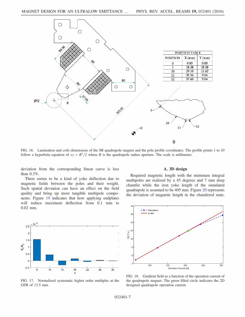
Figure 14 displays the simulated magnetic field insidethe quadrupole where the back legs are removed toaccommodate the vacuum antechamber, while keepingthe field symmetry. Applying a tangential shim on thepole tip results in the field quality lower than desiredvalue of 0.02% within the GFR of �13.5 mm, seeFig. 15. The corresponding 2D mechanical layout is alsogiven in Fig. 16 proposing the lamination dimensions of275 × 275 mm2 with 1 mm thickness. Normalized valuesof the systematic higher order multipole components,calculated by POISSON code [18], are represented inFig. 17.The saturation test was shown in Fig. 18 by sketching
the gradient field versus the current. It depicts that theoperation current of the quadrupole is 207.1 A, and the
FIG. 14. Magnetic field inside the SR quadrupole magnet. Thecolors in the yoke correspond to the field values given on thelegend.
FIG. 15. Quadrupole gradient quality vs horizontal distance.The red points represent �13.5 mm.
TABLE III. Electrical and cooling specifications of the SRdipole magnet.
Parameter Unit Value
Amp-turns per pole A.t 9168Number of turns per coil … 24Current density A=mm2 3.64Conductor cross section mm2 11 × 11
Water cooling tube diameter mm 4.5Voltage drop per magnet V 8.81Power per magnet kW 3.37No. of cooling circuits … 4Water temperature rise °C 5.63Cooling water speed m=s 2.25Pressure drop bar 6
FIG. 13. Perspective mechanical design of the lattice (left) lowfield dipole and (right) the superbend magnet on the same girder.The lateral low field dipole sections are fixed on the girder but themiddle section was installed on different removable plates in bothcases [26].
SAEIDI, RAZAZIAN, RAHIGHI, and POURIMANI PHYS. REV. ACCEL. BEAMS 19, 032401 (2016)
032401-6
deviation from the corresponding linear curve is lessthan 0.3%.There seems to be a kind of yoke deflection due to
magnetic fields between the poles and their weight.Such spatial deviation can have an effect on the fieldquality and bring up more tangible multipole compo-nents. Figure 19 indicates that how applying endplateswill reduce maximum deflection from 0.1 mm to0.02 mm.
A. 3D design
Required magnetic length with the minimum integralmultipoles are realized by a 45 degrees and 7 mm deepchamfer while the iron yoke length of the simulatedquadrupole is assumed to be 405 mm. Figure 20 representsthe deviation of magnetic length in the chamfered state,
FIG. 16. Lamination and coils dimensions of the SR quadrupole magnet and the pole profile coordinates. The profile points 1 to 10follow a hyperbola equation of xy ¼ R2=2 where R is the quadrupole radius aperture. The scale is millimeter.
FIG. 17. Normalized systematic higher order multiples at theGFR of 13.5 mm.
FIG. 18. Gradient field as a function of the operation current ofthe quadrupole magnet. The green filled circle indicates the 2Ddesigned quadrupole operation current.
MAGNET DESIGN FOR AN ULTRALOW EMITTANCE … PHYS. REV. ACCEL. BEAMS 19, 032401 (2016)
032401-7

with 0.2 mm anomaly within the GFR. If necessary, smalladjustments during measurement will be applied on the endroll-off to provide 440 mm magnetic length. The integratedgradient field quality of the quadrupole before and afterchamfering are compared in Fig. 21. That is rewarding toinsure that the field quality improves from 0.1% to 0.01%within the GFR.The final mechanical design of the SR quadrupole, ready
for fabrication, is shown in Fig. 22, though the girder and
FIG. 19. Static mechanical analysis for the SR quadrupole magnet with (right) and without (left) the endplates.
FIG. 20. Effective length variation vs horizontal distance for the405 mm long quadrupole after chamfering.
FIG. 21. Integrated gradient field quality vs horizontal distancefor a 405 mm long quadrupole before and after chamfering.
FIG. 22. Perspective mechanical design of the SR quadrupolewith the endplates [26].
SAEIDI, RAZAZIAN, RAHIGHI, and POURIMANI PHYS. REV. ACCEL. BEAMS 19, 032401 (2016)
032401-8

tilting issues are dissociated. One of the spacers is filledwith the stainless steel block for assembling. It is worthmentioning that the low carbon steel ST52 endplates with15 mm thickness are employed to stack the laminations. Itshysteresis curve is similar to that for the magnet steel andtherefore these endplates are included in the adopted ironlength.
B. Electrical and cooling calculations
The calculated electrical and cooling parameters of theSR quadrupole follow Table IV. Conductor and coolingduct of 7.5 × 7.5 mm2 dimensions with the cooling tubediameter of 3.5 mm is selected to afford optimum currentdensity, power, inductance, cooling water speed andpressure drop here too. The 6 bar pressure drop is regardedto cope well with the unique SR cooling system [25].
V. SEXTUPOLES
ILSF storage ring sextupole magnets are in 8 familieswith additional coils for horizontal, vertical and skewquadrupole corrections.The sextupole magnet has been designed with three-fold
symmetry with one horizontal air gap where the back leg isremoved to accommodate the antechamber of the vacuumchamber. Furthermore, other triplets are connectedmechanically with the stainless steel spacers all alongassembling. It is needed to consider when the trim coilsare implemented and antechamber is wide enough to passthrough the back leg, the yoke is attached by special partswith the same yoke material to preserve correctors’ fieldsymmetry.The maximum sextuple component was taken to be
1200 T=m2 and consequently the pole tip field of 0.4 T [9].The aperture radius of 26 mm has led to 0.5 mm clearancebetween the pole and the vacuum chamber [24]. Thesimulated magnetic field of the sextupole magnet withouttrim coils is shown in Fig. 23. Figure 24 depicts thecorresponding sextupole component quality, lower than
0.02% within �13.5 mm GFR. The 2D mechanical layoutof the sextupole magnet proposing total lamination dimen-sions of 230 × 260 mm2 with 1 mm thickness is shownin Fig. 25.The normalized values of systematic higher order multi-
poles by POISSON are represented in Fig. 26. These errorsare nominal enough to range in the field quality gamut.The higher integrated multipoles are adequately small toexclude the necessity of any chamfer in 3D design. So that,the 344 mm iron length was assumed to reach to the360 mm desired magnetic length.The saturation test is shown in Fig. 27 by sketching the
sextupole component versus the current. It depicts that the
FIG. 23. Magnetic field inside the SR sextupole magnet. Thecolors in the yoke correspond to the field values given on thelegend.
FIG. 24. Sextupole component quality vs horizontal distance.The red points represent �13.5 mm GFR.
TABLE IV. Electrical and cooling specifications of the SRquadrupole magnet.
Parameter Unit Value
Amp-turns per pole A.t 6835Number of turns per coil … 33Current density A=mm2 4.44Conductor cross section mm2 7.5 × 7.5Water cooling tube diameter mm 3.5Voltage drop per magnet V 11.3Power per magnet kW 2.34No. of cooling circuits … 4Water temperature rise °C 8.12Cooling water speed m=s 1.79Pressure drop bar 6
MAGNET DESIGN FOR AN ULTRALOW EMITTANCE … PHYS. REV. ACCEL. BEAMS 19, 032401 (2016)
032401-9

operation current of the sextupole is 140.1 A, which is atthe end of the linear regime.The yoke deflection by magnetic field between the poles
and their weight, which cause some distortion in the field
quality, could be controlled by practicing endplates again.Such endplates represented in Fig. 28 have reduced themaximum deflection from 0.2 mm to 0.004 mm. The lowcarbon steel ST52 endplates with 12 mm thickness are
FIG. 25. Lamination and coils dimensions of the SR sextupole magnet and the pole profile coordinates. The profile points 1 to 6 followa particular equation of 3x2y − y3 ¼ R3 where R is the sextupole radius aperture. The scale is millimeter.
FIG. 26. Normalized systematic higher order multipoles at thereference radius of 13.5 mm.
FIG. 27. Sextupole component as a function of the operationcurrent of the sextupole magnet. The green filled circle indicatesthe 2D designed sextupole operation current.
SAEIDI, RAZAZIAN, RAHIGHI, and POURIMANI PHYS. REV. ACCEL. BEAMS 19, 032401 (2016)
032401-10

employed to stack the laminations and are enclosed in theiron length.The mechanical design of the SR sextupole also has been
finalized and it is in the fabrication process. Figure 29depicts two cases of one with three-fold symmetry with onehorizontal air gap and another with the same pole profilebut connected laminations with the same yoke materialextra parts.
A. Correctors
The sextupole magnets have additional coils forhorizontal, vertical correctors with maximal angle of0.175 mrad, and skew quadrupole correctors. The coilsare powered according to Fig. 30 depending on the desiredcorrections.The geometrical portrait and optimized transverse field
of these correctors are shown in Figs. 31, 32, and 33,respectively. The expected magnetic field for dipolar
correctors is 4.8 mT. The field profile of the skew quadru-pole for the horizontal (Bx) and the vertical (By) compo-nents in the region neighboring the magnetic center is muchmore linear and the gradient for the x and y planes arearound 0.1 ðT=mÞ [28].
B. Electrical and cooling calculations
The electrical and cooling parameters of the designedsextupole are displayed in Table V. The selected hollow
FIG. 28. Static mechanical analysis for the SR sextupole magnet, without (left) and with (right) the endplates.
FIG. 29. Perspective mechanical design of the SR sextupoleswith one horizontal air gap and two non-magnetic steel blocks(left) and with connective magnetic steel blocks (right) [26].
FIG. 30. Coils configurations for the horizontal, vertical andskew quadrupole correctors which are indicated by red, blue andgreen colors respectively.
MAGNET DESIGN FOR AN ULTRALOW EMITTANCE … PHYS. REV. ACCEL. BEAMS 19, 032401 (2016)
032401-11

FIG. 31. Field distribution of the horizontal corrector (left) and designed magnetic field vs horizontal distance (right).
FIG. 32. Field distribution of the vertical corrector (left) and designed magnetic field vs vertical distance (right).
FIG. 33. Field distribution of the skew quadrupole corrector (left) and designed magnetic field vs distance (right).
SAEIDI, RAZAZIAN, RAHIGHI, and POURIMANI PHYS. REV. ACCEL. BEAMS 19, 032401 (2016)
032401-12

conductor dimensions are 6.5 × 6.5 mm2 with the coolingduct diameter of 3.5 mm. All conductor dimensions arechosen in favor of optimum outcomes. The 6 bar pressuredrop is reserved for all coils in the storage ring too. Table VIsummarizes the main electrical corrector parameters.Corrector coils are solid conductors due to the nominalrange of consumed power [25].
VI. CONCLUSIONS
The design of the ultralow emittance ILSF storage ringmagnets have been physically and mechanically described.The proper shims and end chamfers for them are developedand fully determined to meet the field quality and integratedfield uniformity requirements. The designed SR magnetsare now ready for fabrication as prototypes for the ILSF.
ACKNOWLEDGMENTS
The authors would like to specially thank H. Wiedemannfor his many helpful comments on this research. We are
grateful to mechanic group of ILSF especially V. Moradiand J. Dehghani for mechanical designs and drawings.
[1] J. Rahighi, in Proceedings of the International ParticleAccelerator Conference, Kyoto, Japan (ICR, Kyoto,2010), p. 2532; http://ilsf.ipm.ac.ir/.
[2] J. Rahighi et al., in Proceedings of the 2nd InternationalParticle Accelerator Conference, San Sebastián, Spain(EPS-AG, Spain, 2011), p. 2954.
[3] Y. Papaphilippou, A. Ropert, P. Elleaume, and L.Farvacque, in Proceedings of the 21st Particle AcceleratorConference, Knoxville, TN, 2005 (IEEE, Piscataway, NJ,2005), p. 1.
[4] S. Ozaki, J. Bengtsson, S. L. Kramer, S. Krinsky, andV. N. Litvinenko, in Proceedings of the 22nd ParticleAccelerator Conference, PAC-2007, Albuquerque, NM(IEEE, New York, 2007), p. 77.
[5] M. Borland, G. Decker, L. Emery, V. Sajaev, Y. Sun, andA. Xiao, Lattice design challenges for fourth-generationstorage-ring light sources, J. Synchrotron Radiat. 21, 912(2014).
[6] P. F. Tavares, S. C. Leemann, M. Sjöström, and Å.Andersson, The MAX IV storage ring project, J. Synchro-tron Radiat. 21, 862 (2014).
[7] J.-L. Revol et al., in Proceedings of the 4th InternationalParticle Accelerator Conference, Shanghai, China(JACoW, Shanghai, China, 2013), p. 82.
[8] L. Liu, N. Milas, A. H. C. Mukai, X. R. Resende, and F. H.de Sá, The Sirius project, J. Synchrotron Radiat. 21, 904(2014).
[9] H. Ghasem, E. Ahmadi, F. Saeidi, and K. Sarhadi, Beamdynamics of a new low emittance third generation syn-chrotron light source facility, Phys. Rev. ST Accel. Beams18, 030710 (2015).
[10] F. Saeidi, R. Pourimani, J. Rahighi, H. Ghasem, and M.Lamehi Rachti, Normal conducting superbend in an ultra-low emittance storage ring, Phys. Rev. ST Accel. Beams18, 082401 (2015).
[11] J. Guo and T. Raubenheimer, in Proceedings of the 8thEuropean Particle Accelerator Conference, Paris, 2002(EPS-IGA and CERN, Geneva, 2002), p. 1.
[12] R. Nagaoka and A. Wrulich, Emittance minimization withlongitudinal dipole field variation, Nucl. Instrum. MethodsPhys. Res., Sect. A 575, 292 (2007).
[13] Y. Papaphilippou and P. Elleaume, in Proceedings of the21st Particle Accelerator Conference, Knoxville, TN, 2005(IEEE, Piscataway, NJ, 2005), p. 1.
[14] A. Streun and A. Wrulich, Compact low emittance lightsources based on longitudinal gradient bending magnets,Nucl. Instrum. Methods Phys. Res., Sect. A 770, 98 (2015).
[15] A. Shahveh et al., ILSF magnet internal Report No. ILSF-MG-TN-RE07-01-20130701, 2013.
[16] A. Shahveh et al., ILSF magnet internal Report No. ILSF-MG-TN-RE17-00-20140501, 2014.
[17] Finite Element Method Magnetics (FEMM); www.FEMM.info.
[18] POISSON code, Los Alamos National Laboratory ReportNo. LA-UR-87-126, 1987.
TABLE V. Electrical and cooling specifications of the SRsextupole magnet.
Parameter Unit Value
Amp-turns per pole A.t 2957Number of turns per coil … 21Current density A=mm2 4.31Conductor cross section mm2 6.5 × 6.5Water cooling tube diameter mm 3.5Voltage drop per magnet V 8.67Power per magnet kW 1.22No. of cooling circuits … 3Water temperature rise °C 5.81Cooling water speed m=s 1.74Pressure drop bar 6
TABLE VI. Typical electrical corrector specifications.
ParametersHorizontalCorrector
VerticalCorrector
SkewQuadrupolarCorrector
@ 3 GeV(mrad) 0.175 0.175 …Magnetic field (T) 4.8 E-3 4.8 E-3 2.08 E-3
(pole tip field)Ampere-Turns perpole (A.t)
128ð2Þþ64ð4Þ 112 (4) 64(2)
Turns per coil (I) 32þ 16 32 16Conductor size(mm2)
3.15×0.5 3.15×0.5 3.15×0.5
Magnet inductance(mH)
88 95.6 9.94
Current (A) 4 3.5 4Total voltage (V) 17.7 20.6 2.94Total power (W) 71 72.16 11.8
MAGNET DESIGN FOR AN ULTRALOW EMITTANCE … PHYS. REV. ACCEL. BEAMS 19, 032401 (2016)
032401-13

[19] MERMAID code, SIM Limited, Novosibirsk department,630058 Novosibirsk, P. O. Box 160, Russia.
[20] RADIA magnet design code; http://ftp.esrf.eu/pub/InsertionDevices/.
[21] M. Jafarzadeh and E. Yosefi, Power supply group internalreport, 2015.
[22] H. Tarawneh, L.-J. Lindgren, and B. Anderberg, Prototypesoft end dipole magnet for MAX-IV, fabrication andmeasurements, Nucl. Instrum. Methods Phys. Res., Sect.A 546, 620 (2005).
[23] H. Wiedemann (private communication).
[24] O. Seify, Vacuum group internal Report No. ILSF-B-VG-SR00-DES-02-00I, 2014.
[25] J. Tanabe, Iron Dominated Electromagnets Design,Fabrication, Assembly and Measurements (World Scien-tific, Singapore, 2005).
[26] J. Dehghani, V. Moradi, M. Hashemi et al., ILSF mechan-ics internal report, 2015.
[27] DIAMOND Light Source Detailed Design Report, 2002.[28] S. Varnasseri, in Proceedings of the 10th European
Particle Accelerator Conference, Edinburgh, Scotland,2006 (EPS-AG, Edinburgh, Scotland, 2006), p. 2553.
SAEIDI, RAZAZIAN, RAHIGHI, and POURIMANI PHYS. REV. ACCEL. BEAMS 19, 032401 (2016)
032401-14