Physics of 802.11 wireless networks - IJSrudi/sola/Wireless.pdf · aspects such as Maxwell...
18
UNIVERZA V LJUBLJANI FAKULTETA ZA MATEMATIKO IN FIZIKO ODDELEK ZA FIZIKO Seminar 2 Physics of 802.11 wireless networks Elizabeth Dafne Di Rocco Mentor: Prof. dr. Rudolf Podgornik May 13th, 2009 Abstract This document describes the basic physics principles of 802.11 networks. It will cover the theoretical aspects such as Maxwell equations of electromagnetic fields as well as the practical implementation of these concepts when building 802.11 networks. In everyday usage of 802.11 wireless networks the approach is mostly empirical and the physical concepts are most of the time hidden. The purpose of this document is to shed some light into these concepts as to help the wireless LAN engineer better understand the behavior of the network.
Transcript of Physics of 802.11 wireless networks - IJSrudi/sola/Wireless.pdf · aspects such as Maxwell...

UNIVERZA V LJUBLJANI
FAKULTETA ZA MATEMATIKO IN FIZIKO
ODDELEK ZA FIZIKO
Seminar 2
Physics of 802.11 wireless networks
Elizabeth Dafne Di Rocco
Mentor: Prof. dr. Rudolf Podgornik
May 13th, 2009
Abstract
This document describes the basic physics principles of 802.11 networks. It will cover the theoreticalaspects such as Maxwell equations of electromagnetic fields as well as the practical implementation ofthese concepts when building 802.11 networks. In everyday usage of 802.11 wireless networks the approachis mostly empirical and the physical concepts are most of the time hidden. The purpose of this documentis to shed some light into these concepts as to help the wireless LAN engineer better understand thebehavior of the network.

CONTENTS 1
Contents
1 Introduction 2
2 Electromagnetism 2
2.1 Maxwell equations . . . . . . . . . . . . . . . . . . . . . . . . . . . . . . . . . . . . . . . . 2
2.2 Electromagnetic waves . . . . . . . . . . . . . . . . . . . . . . . . . . . . . . . . . . . . . . 3
3 The electromagnetic spectrum 3
4 802.11 protocols 5
4.1 802.11b and 802.11g . . . . . . . . . . . . . . . . . . . . . . . . . . . . . . . . . . . . . . . 5
4.2 802.11i . . . . . . . . . . . . . . . . . . . . . . . . . . . . . . . . . . . . . . . . . . . . . . . 6
4.3 802.11a . . . . . . . . . . . . . . . . . . . . . . . . . . . . . . . . . . . . . . . . . . . . . . 6
4.4 802.11n . . . . . . . . . . . . . . . . . . . . . . . . . . . . . . . . . . . . . . . . . . . . . . 6
5 How is data transmitted? 7
5.1 Modulation . . . . . . . . . . . . . . . . . . . . . . . . . . . . . . . . . . . . . . . . . . . . 7
5.1.1 DSSS . . . . . . . . . . . . . . . . . . . . . . . . . . . . . . . . . . . . . . . . . . . 7
5.1.2 OFDM . . . . . . . . . . . . . . . . . . . . . . . . . . . . . . . . . . . . . . . . . . . 8
6 802.11 antennae 9
6.1 Basic Definitions . . . . . . . . . . . . . . . . . . . . . . . . . . . . . . . . . . . . . . . . . 10
6.2 Isotropic antenna . . . . . . . . . . . . . . . . . . . . . . . . . . . . . . . . . . . . . . . . . 10
6.3 Antenna patterns . . . . . . . . . . . . . . . . . . . . . . . . . . . . . . . . . . . . . . . . . 11
6.4 Antenna types . . . . . . . . . . . . . . . . . . . . . . . . . . . . . . . . . . . . . . . . . . 11
6.4.1 Dipole . . . . . . . . . . . . . . . . . . . . . . . . . . . . . . . . . . . . . . . . . . . 12
6.4.2 Yagi . . . . . . . . . . . . . . . . . . . . . . . . . . . . . . . . . . . . . . . . . . . . 13
7 Signal degradation 14
7.1 Attenuation . . . . . . . . . . . . . . . . . . . . . . . . . . . . . . . . . . . . . . . . . . . . 15
7.2 Multipathing . . . . . . . . . . . . . . . . . . . . . . . . . . . . . . . . . . . . . . . . . . . 15
7.3 Fresnel zones . . . . . . . . . . . . . . . . . . . . . . . . . . . . . . . . . . . . . . . . . . . 15
7.4 Interference . . . . . . . . . . . . . . . . . . . . . . . . . . . . . . . . . . . . . . . . . . . . 16
8 Conclusion 16

1 INTRODUCTION 2
1 Introduction
802.11 wireless networks use electromagnetic waves to transmit data between devices. These waves arebest described by Maxwell equations. There’s a wide spectrum of EM waves that includes visible light,infrared, ultraviolet and radio waves among other. Inside this spectrum in the radio band we find someunlicensed bands that are available to everybody for any type of usage. This unlicensed part of the radiospectrum is used by 802.11 networks.
There are many protocols that regulate 802.11 data transmission. These protocols are developed andratified by the IEEE organization and help manufacturers build devices that can communicate with eachother. These protocols dictate the frequency bands used, modulation, security algorithms, data rates, etc.The most widely know protocols of this family are 802.11b, 802.11g and 802.11a which allow a maximumdata rate of 54Mbps. A new protocol is being developed know as 802.11n which could provide for 10times faster connections. In 802.11b, g and a protocols we use 2 types of modulation techniques: directsequence spread spectrum (DSSS) and orthogonal frequency division multiplexing (OFDM). DSSS is usedfor slower data rates that are described by 802.11b and OFDM for the higher data rates introduced by802.11g and a.
The way we transmit data from the wired network to the wireless client is by using a device called accesspoint. An access point has a transmitter and antennas that actually bridge the signal to the air. Antennashave the task of transmitting the data to the client. For this task antennas are optimized to cover themaximum area possible. Some antennas radiate in all directions equal (omnidirectional) and others havea distinct directional pattern. The most common type of antenna we encounter is the dipole which isomnidirectional. A very good example of directional antennas is the Yagi antenna which is used for bothindoor and outdoor deployment. While antennas try to transmit the signal as far as possible to the clientwe also encounter many barriers: attenuation, multipathing and interference. Sometimes these obstaclescan be eliminated by a good implementation of the network but not always.
2 Electromagnetism
Maxwell equations are the basis for understanding all electromagnetic phenomena. All electrical andelectronic devices available today are possible because we have these basic physics concepts to help us.Maxwell equations explain the relation between electric and magnetic field. In wireless networks, apartfrom the electronics involved, these equations explain the phenomena of electromagnetic waves that makewireless communications possible.
2.1 Maxwell equations
Maxwell equations are the core of 802.11 wireless technology. We will write them in their differentialform:
∇ · ~D = ρ (1)
∇× ~E = −∂ ~B
∂t(2)
∇ · ~B = 0 (3)
∇× ~H = ~j +∂ ~D
∂t(4)
In these equations we have the following quantities:
~E : electric field intensity~D : electric field density
~H : magnetic field intensity~B : magnetic field density
ρ : electric charge densityj : electric current density
We also know the relation between intensity and density for both fields:
~D = εε0~E (5)
3 THE ELECTROMAGNETIC SPECTRUM 3
~B = µµ0~H (6)
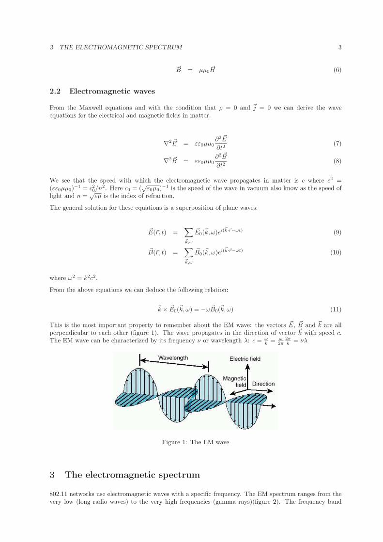
2.2 Electromagnetic waves
From the Maxwell equations and with the condition that ρ = 0 and ~j = 0 we can derive the waveequations for the electrical and magnetic fields in matter.
∇2 ~E = εε0µµ0∂2 ~E
∂t2(7)
∇2 ~B = εε0µµ0∂2 ~B
∂t2(8)
We see that the speed with which the electromagnetic wave propagates in matter is c where c2 =(εε0µµ0)
−1 = c20/n2. Here c0 = (
√ε0µ0)
−1 is the speed of the wave in vacuum also know as the speed oflight and n =
√εµ is the index of refraction.
The general solution for these equations is a superposition of plane waves:
~E(~r, t) =∑
~k,ω
~E0(~k, ω)ei(~k·~r−ωt) (9)
~B(~r, t) =∑
~k,ω
~B0(~k, ω)ei(~k·~r−ωt) (10)
where ω2 = k2c2.
From the above equations we can deduce the following relation:
~k × ~E0(~k, ω) = −ω ~B0(~k, ω) (11)
This is the most important property to remember about the EM wave: the vectors ~E, ~B and ~k are allperpendicular to each other (figure 1). The wave propagates in the direction of vector ~k with speed c.The EM wave can be characterized by its frequency ν or wavelength λ: c = ω
k= ω
2π2πk
= νλ
Figure 1: The EM wave
3 The electromagnetic spectrum
802.11 networks use electromagnetic waves with a specific frequency. The EM spectrum ranges from thevery low (long radio waves) to the very high frequencies (gamma rays)(figure 2). The frequency band

3 THE ELECTROMAGNETIC SPECTRUM 4
from 3kHz up to 300GHz is called the Radio wave band or RF band (figure 3). 802.11 networks use EMwaves with frequencies from this part of the spectrum.
Figure 2: The electromagnetic spectrum [5]
Figure 3: The RF band and its usage [5]
The RF band is not completely open for use by any individual or vendor. Most of the RF band is licensedand anybody who wishes to use these frequencies needs to apply for a license. Examples of this are thebroadcast license and WiMAX license.
There are three unlicensed bands: 900 MHz, 2.4 GHz, and 5.7 GHz (figure 4). Frequencies for thesebands are as follows:
• 900-MHz band: 902. to 928. MHz
• 2.4-GHz band: 2.400 to 2.483 GHz (in Japan extends to 2.495 GHz)
• 5-GHz band: 5.150 to 5.350 MHz, 5.725 to 5.825 MHz, with some countries supporting middlebands between 5.350 and 5.825 MHz.
802.11 networks use frequencies that are unlicensed. Vendors can therefore design products that use thesefrequencies and users can freely build networks. This freedom however comes at a price because anybodycan use these frequencies for any purpose. Networks using unlicensed frequency bands are susceptibleto interference from a variety of sources. 802.11b/g networks operate in the 2.4GHz band and the mostcommon sources of interference for these networks are microwave ovens, cordless phones and bluetoothdevices. 802.11a networks operate in the 5GHz band which is also used by satellites and radars. In thislast case a protocol (802.11h) was created to avoid interference from 802.11a with radar transmissions.

4 802.11 PROTOCOLS 5
Figure 4: Unlicensed frequency bands [1]
4 802.11 protocols
In the world of networking a protocol is a set of rules that determine the format and transmission ofdata. A protocol defines all aspects necessary for devices to communicate without problems. These caninclude physical properties (voltage, power, frequencies, etc.), logical interpretation of signals (numberof bits, fields in a packet, etc) and behaviour of devices (retries, beacons, etc). 802.11 wireless networkscomprise a wide set of protocols that regulate them. I will briefly discuss the most important protocolsof this set.
4.1 802.11b and 802.11g
As mentioned before these protocols use the 2.4 GHz frequency band. 802.11b allows a maximum trough-put of 11 Mbps and was ratified by the IEEE organization in 1999 (for more information about IEEEyou can visit www.ieee.com). 802.11g allows a maximum troughput of 54 Mbps and was ratified in 2003.Keep in mind that the wireless network is a shared medium and only one device can speak at a time.802.11g defines backward compatibility with 802.11b devices which means that a network can includeboth types of devices. The maximum transmit power output allowed for a device is 100mW. Accordingto these protocols the 2.4 GHz frequency band is divided into channels. Each of these channels is 22 MHzwide. In North America (FCC regulation) there are 11 allowed channels, in Europe (ETSI regulation)there are 13, in Japan there are 14. However not all of these channels can be used simultaneously. Onlythree channels are non-overlapping (figure 5). If we use three 802.11g access points each on a differentchannel we can get a troughput of 162 Mbps. In a larger environment with many transmitters we canminimize interference between them by assigning different channels to adjacent units.
Figure 5: 802.11b and 802.11g channels [1]

4 802.11 PROTOCOLS 6
4.2 802.11i
This protocol dictates only security rules. The protocol includes among other algorithms for authenti-cation of devices and encryption of data. This protocol is also know as WPA2 (Wi-Fi Protected Access2).
4.3 802.11a
This protocol uses the 5 GHz frequency band. It provides the same maximum troughput as 802.11g(54 Mbps) and was ratified by the IEEE in 1999. Regulations for 802.11a vary from country to countrysince this frequency band is used by military, radars, satellites, etc. Some countries don’t allow 802.11anetworks while others limit the usage to only some channels. The 5GHz unlicensed band is divided into3 frequency bands: UNII-1, UNII-2 in UNII-3 (figure 6). 802.11a divides each of these bands into fournon-overlapping channels which gives a total of 12 channels. By ETSI standards only UNII-1 and UNII-2channels are allowed. The total bandwidth we can achieve using 8 access points is 648 Mbps.
Figure 6: 802.11a channels [1]
4.4 802.11n
This is the latest protocol being developed by the IEEE. It’s the next step regarding data troughput.Although many manufacturers claim to have 802.11n compliant products the actual protocol has not yetbeen ratified. The currently available devices are 802.11n draft 1 or 2 compliant only. The protocol allowsfor a maximum of 600 Mbps troughput depending on the implementation. This protocol will include thefollowing improvements:
• Use of both 2.4 GHz and 5 GHz frequency bands.
• Channel bonding which agregates two 20 MHz channels into one 40 MHz channel. This allows fora higher data rate but decreases the number of channels available.
• MIMO (multiple input multiple outpu) technology which utilizes multipath signals to the advan-tage of the wireless network. In a non-MIMO based 802.11a/b/g network, multipath signals wereperceived as interference degrading a receiver’s ability to recover the message information in thesignal. MIMO uses the multipath signal’s diversity to increase a receiver’s ability to recover themessage information from the signal. With MIMO the signal is transmited by multiple antennasand received also by multiple antennas.

5 HOW IS DATA TRANSMITTED? 7
5 How is data transmitted?
Now that we know what type of waves are used in 802.11 networks the following questions arise: how isdata transmitted over the EM waves? what determines the throughput we can achieve? how does noiseinfluence the transmission? how does the network handle the loss of bits? The answer to these questionsis modulation. Different types of modulations achieve different data rates.
As a receiver moves farther from a transmitter, the signal gets weaker, and the difference between thesignal and noise decreases. At some point, the signal cannot be distinguished from the noise, andloss of communication occurs. The amount of compression (or modulation type) at which the signalis transmitted determines the amount of signal necessary to be clearly received through the noise. Astransmission or modulation schemes (compression) become more complex and data rate goes up, immunityto noise decreases, and coverage goes down. In 802.11 networks when the signal becomes too weak toreceive data at a given data rate the transmitter switches to a slower connection. However at some pointeven the slowest data rate (1 Mbps) can not be sustained and connection is lost.
5.1 Modulation
There are many types of modulationtechniques that are used to compressdata. This is because there are manyways in which the EM wave can bemodulated (figure 7).
Figure 7: Modulation examples [4]
5.1.1 DSSS
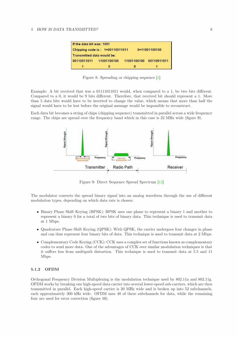
802.11b protocol uses DSSS (Direct Sequence Spread Spectrum) modulation techniques. Spread-spectrumtechniques take a modulation approach that uses a much higher than necessary spectrum bandwidth tocommunicate information at a much lower rate. Each bit is replaced or spread by a wideband spreadingcode. This modulation has the ability to operate in low signal-to-noise ratio (SNR) conditions. Thespreading sequence converts a data bit into chips (figure 8). This results in greater immunity to radiofrequency interference. A feature of these codes is that the receiver could actually miss several bits andthe software would still be able to identify that the code was intended to be a 1 or a 0. If there were aninterfering signal, the unit would still be able to get the data through without loss of data or reductionin throughput or performance.
5 HOW IS DATA TRANSMITTED? 8
Figure 8: Spreading or chipping sequence [1]
Example: A bit received that was a 01111011011 would, when compared to a 1, be two bits different.Compared to a 0, it would be 9 bits different. Therefore, that received bit should represent a 1. Morethan 5 data bits would have to be inverted to change the value, which means that more than half thesignal would have to be lost before the original message would be impossible to reconstruct.
Each data bit becomes a string of chips (chipping sequence) transmitted in parallel across a wide frequencyrange. The chips are spread over the frequency band which in this case is 22 MHz wide (figure 9).
Figure 9: Direct Sequence Spread Spectrum [12]
The modulator converts the spread binary signal into an analog waveform through the use of differentmodulation types, depending on which data rate is chosen:
• Binary Phase Shift Keying (BPSK): BPSK uses one phase to represent a binary 1 and another torepresent a binary 0 for a total of two bits of binary data. This technique is used to transmit dataat 1 Mbps.
• Quadrature Phase Shift Keying (QPSK): With QPSK, the carrier undergoes four changes in phaseand can thus represent four binary bits of data. This technique is used to transmit data at 2 Mbps.
• Complementary Code Keying (CCK): CCK uses a complex set of functions known as complementarycodes to send more data. One of the advantages of CCK over similar modulation techniques is thatit suffers less from multipath distortion. This technique is used to transmit data at 5.5 and 11Mbps.
5.1.2 OFDM
Orthogonal Frequency Division Multiplexing is the modulation technique used by 802.11a and 802.11g.OFDM works by breaking one high-speed data carrier into several lower-speed sub-carriers, which are thentransmitted in parallel. Each high-speed carrier is 20 MHz wide and is broken up into 52 subchannels,each approximately 300 kHz wide. OFDM uses 48 of these subchannels for data, while the remainingfour are used for error correction (figure 10).

6 802.11 ANTENNAE 9
Figure 10: Orthogonal Frequency Division Multiplexing [1]
Each sub-channel in the OFDM implementation is about 300 kHz wide. At the low end of the speedgradient, BPSK is used to encode 125 kbps of data per channel, resulting in a 6000-kbps, or 6-Mbps,data rate. Using QPSK, you can double the amount of data encoded to 250 kbps per channel, yieldinga 12-Mbps data rate. And by using 16-state quadrature amplitude modulation (16-QAM) encoding 4bits per cycle, you can achieve a data rate of 24 Mbps. The 802.11a standard specifies that all 802.11a-compliant products must support these basic data rates. The standard also lets the vendor extend themodulation scheme beyond 24 Mbps. Data rates of 54 Mbps are achieved by using 64-state quadratureamplitude modulation (64-QAM), which yields 8 bits per cycle or 10 bits per cycle, for a total of up to1.125 Mbps per 300-kHz channel. With 48 channels, this results in a 54-Mbps data rate 11. Remember,the more bits per cycle (hertz) that are encoded, the more susceptible the signal is to interference, andultimately the shorter the range, unless power output is increased.
Figure 11: OFDM subchannel modulation types [1]
802.11g uses both DSSS and OFDM modulation for backward compatibility with 802.11b devices. It usesOFDM for 802.11g data rates (54, 48, 36, 24, 18, 12, 9, and, 6 Mbps) and DSSS for 802.11b data rates(11, 5.5, 2, and, 1 Mbps).
6 802.11 antennae
The most vital piece of equipment in a 802.11 network is the access point. This is the device thatserves as a bridge between the wireless and the wired network. It has all the logic and the transmitternecessary for radiating the EM waves. The architecture of an access point itself will not be covered inthis document. The radiating element of an access point are the antennas attached to it. In this sectionwe will discuss common antennae and their properties.
6 802.11 ANTENNAE 10
6.1 Basic Definitions
We often define antennae and antenna terminology in terms of a transmitting antenna, but all thedefinitions apply to receiving antennae as well. In fact, an antenna’s properties are the same in eitheroperating mode. This is true because Maxwell’s equations are symmetric with respect to time.
When reading antenna specifications the most common unit we find is dB = 10 log10P1
P0
. The three dBunits we usually encounter are:
• dBm where we compare power to 1mW
• dBi where antenna gain is compared with an isotropic radiator
• dBd where antenna gain is compared to a dipole antenna
Antenna gain is the amount of increase in energy that an antenna appears to add to an RF signal. Thegain of an antenna (in any given direction) is defined as the ratio of the power gain in a given directionto the power gain of a reference antenna in the same direction. It is standard practice to use an isotropicradiator as the reference antenna in this definition. To convert any number from dBd to dBi, simplyadd 2.14 to the dBd number. Note that when a single number is stated for the gain of an antenna, it isassumed that this is the maximum gain (the gain in the direction of the maximum radiation).
In RF, you have to give up something to gain something else. In antenna gain, this comes in the form ofcoverage angle, known as beamwidth. Beamwidth is defined as the area or angle in which the majority ofthe signal is transmitted. As the gain of an antenna goes up, the beamwidth angle goes down, allowingfurther distances to be achieved (at the expense of other directions).
The 3-dB beamwidth (or half-power beamwidth) of an antenna is typically defined for each of theprincipal planes. The 3-dB beamwidth in each plane is defined as the angle between the points in themain lobe that are down from the maximum gain by 3 dB. This is shown in figure 14 in the followingsection. The 3-dB beamwidth in the plot in this figure is shown as the angle between the two blue linesin the polar plot. In this example, the 3-dB beamwidth in this plane is about 37 degrees. Antennae withwide beamwidths typically have low gain and antennae with narrow beamwidths tend to have highergain. Remember that gain is a measure of how much of the power is radiated in a given direction. Soan antenna that directs most of its energy into a narrow beam (at least in one plane) will have a highergain.
Most antennae available are described as vertically polarized. This means that the EM wave islinearly polarized and the electric field is oriented vertically if the antenna is placed upright. Someantennae have markings showing in which direction the wave is polarized and therefore how the antennashould be mounted. Antennae with the same polarization provide the best transmission/reception path.When mounting antennae we need to be careful about orientation to avoid placing the transmitting andreceiving antennae with perpendicular polarizations.
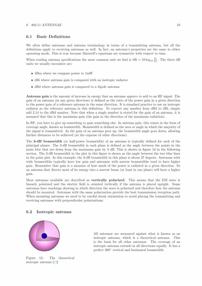
6.2 Isotropic antenna
Figure 12: The theoreticalisotropic antenna [13]
All antennae are measured against what is known as anisotropic antenna, which is a theoretical antenna. Thisis the basis for all other antennae. The coverage of anisotropic antenna extends in all directions equally. It has aperfect 360◦ vertical and horizontal beamwidth.

6 802.11 ANTENNAE 11
6.3 Antenna patterns
The radiation pattern or antenna pattern is the graphical representation of the radiation properties ofthe antenna as a function of space. That is, the antenna’s pattern describes how the antenna radiatesenergy out into space (or how it receives energy). It is important to state that an antenna radiatesenergy in all directions, at least to some extent, so the antenna pattern is actually three-dimensional.It is common, however, to describe this 3D pattern with two planar patterns, called the principal planepatterns. These principal plane patterns can be obtained by making two slices through the 3D patternthrough the maximum value of the pattern or by direct measurement. It is these principal plane patternsthat are commonly referred to as the antenna patterns.
In discussions of principal plane patterns or even antennapatterns, you will frequently encounter the terms azimuth
plane pattern and elevation plane pattern. The term az-imuth is commonly found in reference to "the horizontal"whereas the term elevation commonly refers to "the verti-cal". When used to describe antenna patterns, these termsassume that the antenna is mounted (or measured) in theorientation in which it will be used. In figure 13, the x-yplane (θ = 90◦) is the azimuth plane. The elevation plane isthen a plane orthogonal to the x-y plane, say the y-z plane(φ = 90◦). The antenna patterns (azimuth and elevationplane patterns) are frequently shown as plots in polar coor-dinates. This gives the viewer the ability to easily visualizehow the antenna radiates in all directions as if the antennawas mounted already.
Figure 13: Antenna measure-ment coordinate system [10]
In figure 14 we can see two different representations of radiation patterns. The quantity plotted is antennagain in all directions with respect to the maximum gain (at 0◦). The figure shows the different lobes ofthe antenna as well as the 3dB-beamwidth.
Figure 14: Radiation patterns [10]
6.4 Antenna types
There are many different types of antennae. In this section I will describe some of the most commonantennae used in 802.11 networks.

6 802.11 ANTENNAE 12
Figure 15: Various antennae commonly found in WLAN systems [10]
6.4.1 Dipole
A dipole antenna most commonly refers to a half-wavelength (λ/2) dipole. The physical antenna (notthe package that it is in) is constructed of conductive elements whose combined length is about half of awavelength at its intended frequency of operation. This is a simple antenna that radiates its energy outtoward the horizon (perpendicular to the antenna). The patterns shown in figure 16 are those resultingfrom a perfect dipole formed with two thin wires oriented vertically along the z-axis. The resulting 3Dpattern looks kind of like a donut or a bagel with the antenna sitting in the hole and radiating energyoutward. The strongest energy is radiated outward, perpendicular to the antenna in the x-y plane. Theazimuth plane pattern is formed by slicing through the 3D pattern in the horizontal plane, the x-y planein this case, just as you would slice through a bagel. Notice that the azimuth plane pattern is non-directional, that is, the antenna radiates its energy equally in all directions in the azimuth plane. Thedipole antenna is therefore omnidirectional. The elevation plane pattern is formed by slicing the 3Dpattern through an orthogonal plane (either the x-z plane or the y-z plane).
The gain of the half-wave dipole is approximately 2.2 dBi. The value of 2.2 dBi is achieved at the horizonin the elevation plane and everywhere in the azimuth plane. Note that the azimuth plane pattern is acircle passing through the gain value of 2.2 dBi at all angles. From the elevation plane pattern we see thatthe dipole antenna has an elevation plane beamwidth of 78-degrees as indicated on the pattern in figure16-d by the two blue lines. Given these antenna patterns, you can see that a dipole antenna should bemounted so that it is vertically oriented with respect to the floor or ground. This results in the maximumamount of energy radiating out into the intended coverage area. The null in the middle of the patternwill point up and down. Indoors, this typically is not a concern because of the close proximity of theceiling and all the multipath present in the indoor environment.

6 802.11 ANTENNAE 13
Figure 16: Dipole antenna and its patterns [10]
6.4.2 Yagi
Directional antennas are used for coverage as well as point-to-point links. They can be patch antennas,dishes, horns or a whole host of other varieties. They all accomplish the same goal: radiating their energyout in a particular direction. One example of this is the Yagi antenna (named after Hidetsugu Yagi whichco-invented the antenna together with Shintaro Uda).
A Yagi antenna is formed by driving a simple antenna, typically a dipole or dipole-like antenna, andshaping the beam using a well-chosen series of non-driven elements whose length and spacing are tightlycontrolled. The Yagi shown here in figure 17 is built with one reflector (the bar behind the driven antenna)and 14 directors (the bars in front of the driven antenna). This configuration yields a gain of about 15dBi with azimuth and elevation plane beamwidths that are basically the same, around 36 degrees. Thatis a common feature of Yagi antennas. Many times these antennas are designed so that they can berotated for either horizontal or vertical polarization, so having the same 3-dB beamwidth in each planeis a nice feature in those instances.

7 SIGNAL DEGRADATION 14
Figure 17: Yagi antenna and its patterns [10]
7 Signal degradation
All types of wireless networks experience signal degradation. There are many reasons why a signal thattravels from a transmitter to a receiver loses its signal strength. Since a signal from an antenna radiatesin all directions we lose power first of all due to the distance between the transmitter and the receiver.The power radiated by the transmitter is dissipated in all directions. In an ideal isotropic antenna thismeans that the power of the signal falls as 1/r2 where r is the distance to the transmitter. In a realantenna we find some directions with higher gain and in those directions the power is higher than in anisotropic antenna. But still the power falls with distance. This is something that can’t be avoided. Wetrade antenna gain for coverage which simply means that some antennas will have better range. Thelevel of the signal is usually know as RSSI (Radio Signal Strength Indicator) (figure 18).
There are however other causes for power loss and signal degradation that can be avoided or at leastmitigated. The most common quantity we use to determine how good the signal is at a given pointis the SNR (signal to noise ratio) (figure 18). With higher data rates and more complex modulationtechniques we need a higher SNR to be able to understand the transmission. The RSSI and SNRquantities are included in 802.11 packets and can be used by the devices to improve connection bychanging the modulation or maybe boosting power levels.

7 SIGNAL DEGRADATION 15
Figure 18: SNR and RSSI concepts [6]
7.1 Attenuation
Attenuation is the loss in amplitude that occurs whenever a signal travels through wire, free space or anobstruction. When a radio wave reaches an obstacle, some of its energy is absorbed and converted intoanother kind of energy, while another part is attenuated and continues to propagate (and another partmay be reflected). The amount of energy absorbed depends mainly on the frequency of the EM waveand the material of the obstacle. For 802.11 networks we have here some very rough estimates for somecommon construction elements:
Plasterboard wall 3dBGlass wall with metal frame 6dBCinder block wall 4dBOffice window 3dBMetal door 6dBMetal door in brick wall 12.4dB
Table 1: Attenuation for some common construction elements [14]
7.2 Multipathing
Multipath reflection occurs when reflections cause more than one copy of the same transmission to arriveat the receiver at slightly different times. These reflected signals sometimes cause problems at the receiverby partially canceling the direct signal, effectively reducing the amplitude. The link throughput slowsdown because the receiver needs more time to either separate the real signal from the reflected echoes orto wait for missed frames to be retransmitted.
7.3 Fresnel zones
For outdoor links (point to point or point to multipoint) is very important to have a clear line of sightbetween the antennas. In this type of deployment we usually have directional antennae. But how dowe decide line of sight? A wireless line of sight typically requires visual line of sight plus additionalpath clearance to account for the spreading of the wireless signal. The shorter the wavelength of anelectromagnetic wave, the less clearance it needs from objects that it passes as it travels between twopoints. The amount of clearance required for obstacles is expressed in terms of Fresnel zones. Fresnelzones consist of series of concentric ellipsoid surfaces that surround the straight-line path between the

8 CONCLUSION 16
transmitter and receiver. The first Fresnel zone is defined as the surface containing every point for whichthe distance from the transmitter to any reflection point on the surface and then on the receiver is onehalf-wavelength longer than the direct signal path. As radio signals travel through free space to theirintended target, they may encounter an obstruction in the Fresnel area, degrading the signal. Figure 19illustrates the Fresnel zone between two antennas. As long as 60 percent of the first Fresnel (F1) zone isclear of obstructions, the link behaves essentially the same as a clear freespace path.
Figure 19: 1st Fresnel zone [6]
7.4 Interference
Since the frequency bands used in 802.11 is unlicensed there are many devices that can cause interference.Among the most common sources of interference are microwave ovens, bluetooth devices, radar andcordless phones. The only way we can avoid the sources of interference is by changing the frequencychannel. Some products are able to do this automatically but this is not covered by 802.11 protocols.Sometimes even changing the channel doesn’t help because the source of interference is occupying a bandtoo wide.
8 Conclusion
Implementation of 802.11 networks is a very empirical work. The first steps are usually determining thetype of network to be implemented (5 GHz or 2.4 GHz, point-to-point or client coverage, high or lowerthroughput, etc.). The most important task to ensure a good RF coverage and a resilient network is thesite survey of the building or area to cover. The site survey consist of testing different access points andantennae to understand the RF properties of the area and to select the right equipment. The site surveyis therefore an empirical way to predict how will EM waves travel. In a real world situation is almostimpossible to predict this using a theoretical model. However, the theoretical model can be of greatassistance to understand the results of the coverage measurements. A good knowledge of the physicalproperties described in this document can help us avoid interference, multi-pathing, attenuation of thesignal and other problems usually encountered in 802.11 networks.
The protocols presented in this document reflect the current status of 802.11 networks. Improvements andupgrades are constantly being introduced and therefore also new protocols are developed to standardizeequipment. 802.11n is the next protocol to be ratified and it will provide for higher data rates and a moreresilient wireless network. Physicists and engineers work every day to develop new and better technologiesand products.

REFERENCES 17
References
[1] Cisco Systems: Cisco Wireless LAN Fundamentals v1.0, Cisco Systems (2006)
[2] James William Rohlf: Modern Physics, John Wiley & Sons (1994)
[3] Rudi Podgornik: Elektromagnetno polje, Skripta (2001)
[4] Pejman Roshan and Jonathan Leary: 802.11 Wireless LAN Fundamentals, Cisco Press (2004)
[5] Wikipedia: http://en.wikipedia.org (April 29th 2009)
[6] Cisco Systems Wireless Technologies: http://www.cisco.com/go/wireless (May 12th 2009)
[7] Ron Vignieri: Radio Physics for Wireless Devices and Networking, Download fromhttp://hardware.ittoolbox.com/documents/peer-publishing (February 5th 2009)
[8] Joseph Bardwell: Math and Physics for the 802.11 Wireless LAN Engineer, Download fromhttp://www.wildpackets.com/elements/whitepapers/math_physics_jbardwell.pdf (February 5th2009)
[9] Joshua Bardwell: The Truth About 802.11 Signal And Noise Metrics, Download fromhttp://www.connect802.com/download/techpubs/2004/you_believe_D100201.pdf (February 14th2009)
[10] Cisco Systems: Antenna Patterns and Their Meaning (White Paper), Download fromhttp://www.cisco.com/en/US/products/hw/wireless/ps469/prod_white_papers_list.html (April20th 2009)
[11] Wireless LAN Association: High Speed Wireless LAN Options, Download fromhttp://www.wlana.org/pdf/highspeed.pdf (May 3rd 2009)
[12] Ake Severinson: The automation engineer’s guide to wireless technology Part 1 - The physics ofradio, Download fromwww.isa.org/standards/downloads/sp100/The_Physics_of_Radio-A_Tutorial(Draft_1_4_SP-100).doc(May 3rd 2009)
[13] Dr. R. K. Rao: Wireless Radio Propagation & Antennas Fundamentals, Download fromwww.engga.uwo.ca/people/rrao/SE-410-2006/Lectures-11.ppt (May 1st 2009)
[14] Jim Geier: Beating signal loss in WLANs, http://www.wi-fiplanet.com/tutorials/article.php/1431101(May 12th 2009)