


Physics in Radiation Oncology Self-Assessment Guidedl.mehrsys.ir/pdf-books/Physics in...
479
www.myuptodate.com
Transcript of Physics in Radiation Oncology Self-Assessment Guidedl.mehrsys.ir/pdf-books/Physics in...

Physics in Radiation oncology self-assessment guide
Edited by
Andrew Godley, PhDStaff Physicist
Department of Radiation OncologyTaussig Cancer Institute
Cleveland ClinicCleveland, Ohio
Ping Xia, PhDHead of Medical Physics
Professor of Molecular MedicineDepartment of Radiation Oncology
Taussig Cancer InstituteCleveland ClinicCleveland, Ohio
New York
Visit our website at www.demosmedical.com
ISBN: 9781620700709e-book ISBN: 9781617052408
Acquisitions Editor: Rich WintersCompositor: diacriTech
© 2016 Demos Medical Publishing, LLC. All rights reserved. This book is protected by copyright. No part of it may be reproduced, stored in a retrieval system, or transmitted in any form or by any means, electronic, mechanical, photocopying, recording, or otherwise, without the prior written permission of the publisher.
Medicine is an ever-changing science. Research and clinical experience are continually expanding our knowledge, in particular our understanding of proper treatment and drug therapy. The authors, editors, and publisher have made every effort to ensure that all information in this book is in accordance with the state of knowledge at the time of production of the book. Nevertheless, the authors, editors, and publisher are not responsible for errors or omissions or for any consequences from application of the information in this book and make no warranty, expressed or implied, with respect to the contents of the publication. Every reader should examine carefully the package inserts accompanying each drug and should carefully check whether the dosage schedules mentioned therein or the contraindications stated by the manufacturer differ from the statements made in this book. Such examination is particularly important with drugs that are either rarely used or have been newly released on the market.
Library of Congress Cataloging-in-Publication Data
Physics in radiation oncology : self-assessment guide / editors, Andrew Godley, Ping Xia. p. ; cm. Includes bibliographical references and index. ISBN 978-1-62070-070-9 I. Godley, Andrew, editor. II. Xia, Ping (Radiation oncologist), editor. [DNLM: 1. Health Physics–methods—Examination Questions. 2. Neoplasms—radiotherapy— Examination Questions. QZ 18.2] RC271.R3 616.99’40642076—dc23 2015015028
Printed in the United States of America by Gasch.15 16 17 18 / 5 4 3 2 1
Special discounts on bulk quantities of Demos Medical Publishing books are available to corporations, professional associations, pharmaceutical companies, health care organizations, and other qualifying groups. For details, please contact:
Special Sales DepartmentDemos Medical Publishing, LLC11 West 42nd Street, 15th FloorNew York, NY 10036Phone: 800-532-8663 or 212-683-0072Fax: 212-941-7842E-mail: [email protected]

contents
v
Contributors viiPreface ix
1. Fundamental Physics 1Mihir Naik and Andrew Godley 1.1 Units 31.2 Atomic and Nuclear Structure 71.3 Radioactivity 151.4 Exponential Decay 21
2. Radiation Generating Equipment 29Qingyang Shang and Matthew Kolar 2.1 Production of X-Rays 312.2 Linear Accelerators 412.3 Particle and Source-Based Radiation 51
3. Ionizing Radiation 57Zhilei Liu Shen and Toufik Djemil 3.1 Photon Interactions 593.2 Particle Interactions 71
4. Absorbed Dose 85Martin Andrews and Naichang Yu 4.1 Dosimetry 874.2 Dosimeters 97
5. Photon Treatment 113Matthew C. Ward and Salim Balik 5.1 Beam Quality 1155.2 Factors Affecting Photon Dose Deposition 1295.3 Monitor Unit Calculations 149
6. Basic Treatment Planning 165Jeff Kittel, Lisa Zickefoose, and Diana Mattson
7. Electron Treatment 201Matthew Vossler and Anthony Mastroianni
Share Physics in Radiation Oncology Self-Assessment Guide

vi
Contents
8. Brachytherapy 223Maria Rybak, Neil Woody, and Allan Wilkinson 8.1 Brachytherapy 2258.2 Low-Dose-Rate Brachytherapy 2358.3 High-Dose-Rate Brachytherapy 245
9. Advanced Treatment Techniques 263Anthony Magnelli, Tingliang Zhuang, and Toufik Djemil 9.1 Intensity Modulated Radiation Therapy 2659.2 Stereotactic Radiation Therapy 2759.3 Respiratory Management 2879.4 Computing 291
10. Specialized Treatment 295Yvonne Pham and Gennady Neyman 10.1 Stereotactic Radiosurgery 29710.2 Total Body and Total Skin Irradiation 30710.3 Particle Therapy 31510.4 Hyperthermia 327
11. Quality 333Peng Qi and Anthony Magnelli 11.1 Therapy Equipment Quality Assurance 33511.2 Patient Safety 347
12. Radiation Safety and Regulations 357Mike Strongosky and Henry Blair 12.1 Rules and Regulations 35912.2 Shielding 375
13. Diagnostic Imaging 385Kevin Wunderle, Nicholas Shkumat, and Frank Dong 13.1 Radiography and Fluoroscopy 38713.2 MRI 39313.3 Mammography 39913.4 Nuclear Imaging 40313.5 CT 40913.6 Ultrasound 417
14. Image Guidance 425Eric Tischler and Lama Muhieddine Mossolly
Index 457

contRiButoRs
Martin Andrews, PhDDepartment of Radiation OncologyTaussig Cancer InstituteCleveland ClinicCleveland, Ohio
Salim Balik, PhDDepartment of Radiation OncologyTaussig Cancer InstituteCleveland ClinicCleveland, Ohio
Henry Blair, MDDepartment of Radiation OncologyTaussig Cancer InstituteCleveland ClinicCleveland, Ohio
Toufik Djemil, PhDDepartment of Radiation OncologyTaussig Cancer InstituteCleveland ClinicCleveland, Ohio
Frank Dong, PhDDiagnostic RadiologyImaging InstituteCleveland ClinicCleveland, Ohio
Andrew Godley, PhDDepartment of Radiation OncologyTaussig Cancer InstituteCleveland ClinicCleveland, Ohio
Jeff Kittel, MDDepartment of Radiation OncologyTaussig Cancer InstituteCleveland ClinicCleveland, Ohio
Matthew Kolar, MSDepartment of Radiation OncologyTaussig Cancer InstituteCleveland ClinicCleveland, Ohio
Anthony Magnelli, MSDepartment of Radiation OncologyTaussig Cancer InstituteCleveland ClinicCleveland, Ohio
Anthony Mastroianni, MDDepartment of Radiation OncologyTaussig Cancer InstituteCleveland ClinicCleveland, Ohio
Diana Mattson, CMDDepartment of Radiation OncologyTaussig Cancer InstituteCleveland ClinicCleveland, Ohio
Lama Muhieddine Mossolly, MSDepartment of Radiation OncologyTaussig Cancer InstituteCleveland ClinicCleveland, Ohio
vii

viii
Contributors
Mihir Naik, DODepartment of Radiation OncologyTaussig Cancer InstituteCleveland ClinicCleveland, Ohio
Gennady Neyman, PhDDepartment of Radiation OncologyTaussig Cancer InstituteCleveland ClinicCleveland, Ohio
Yvonne Pham, MDDepartment of Radiation OncologyTaussig Cancer InstituteCleveland ClinicCleveland, Ohio
Peng Qi, PhDDepartment of Radiation OncologyTaussig Cancer InstituteCleveland ClinicCleveland, Ohio
Maria Rybak, MSDepartment of Radiation OncologyTaussig Cancer InstituteCleveland ClinicCleveland, Ohio
Qingyang Shang, PhDDepartment of Radiation OncologyTaussig Cancer InstituteCleveland ClinicCleveland, Ohio
Zhilei Liu Shen, PhDDepartment of Radiation OncologyTaussig Cancer InstituteCleveland ClinicCleveland, Ohio
Nicholas Shkumat, MSDiagnostic RadiologyImaging InstituteCleveland ClinicCleveland, Ohio
Mike Strongosky, MSDepartment of Radiation OncologyTaussig Cancer InstituteCleveland ClinicCleveland, Ohio
Eric Tischler, MSDepartment of Radiation OncologyTaussig Cancer InstituteCleveland ClinicCleveland, Ohio
Matthew Vossler, MSDepartment of Radiation OncologyTaussig Cancer InstituteCleveland ClinicCleveland, Ohio
Matthew C. Ward, MDDepartment of Radiation OncologyTaussig Cancer InstituteCleveland ClinicCleveland, Ohio
Allan Wilkinson, PhDDepartment of Radiation OncologyTaussig Cancer InstituteCleveland ClinicCleveland, Ohio
Neil Woody, MDDepartment of Radiation OncologyTaussig Cancer InstituteCleveland ClinicCleveland, Ohio
Kevin Wunderle, MSDiagnostic RadiologyImaging InstituteCleveland ClinicCleveland, Ohio
Naichang Yu, PhDDepartment of Radiation OncologyTaussig Cancer InstituteCleveland ClinicCleveland, Ohio
Tingliang Zhuang, PhDDepartment of Radiation OncologyTaussig Cancer InstituteCleveland ClinicCleveland, Ohio
Lisa Zickefoose, CMDDepartment of Radiation OncologyTaussig Cancer InstituteCleveland ClinicCleveland, Ohio

PReface
We are delighted to introduce the first edition of the Physics in Radiation Oncology Self-Assessment Guide. This guide provides a comprehensive physics review for anyone in the Radiation Oncology field. It partners the 2013 release of the Radiation Oncology Self-Assessment Guide, enhancing the resources available to scholars of radiation oncology. This book was designed as a flash card, question and answer style to help reinforce concepts and provide a focused review of medical physics. The detailed answers allow the reader to learn through completing the questions. The topics covered are expansive and thorough, effectively covering the same range as a radiation oncology physics text.
The guide has been divided into 14 chapters, leading the reader through the radiation oncology physics field, from basic physics to current practice and latest innovations. Basic physics covers fundamentals, photon and particle interactions, and dose measurement. All of current practice is included; treatment planning, safety, regulations, quality assurance, and SBRT, SRS, TBI, IMRT, and IGRT techniques. A unique aspect of the guide is its chapter dedicated to the topics in diagnostic imaging most relevant to radiation oncology, covering MRI, ultrasound, fluoroscopy, mammography, PET, SPECT, and CT. New technologies, such as VMAT, novel IGRT devices, proton therapy, and MRI-guided therapy, are also incorporated.
This book has been written by the medical physicists in the Department of Radiation Oncology at the Cleveland Clinic Taussig Cancer Institute with help from the entire department including radiation oncology residents, dosimetrists, and staff physicians; and our physicist colleagues in the Imaging Institute at the Cleveland Clinic. It is our sincere wish that this guide becomes an excellent resource for anyone wishing to reinforce their knowledge of medical physics.
Andrew Godley, PhDPing Xia, PhD
ix

Share Physics in Radiation Oncology Self-Assessment Guide
1FUNDAMENTAL PHYSICS
MIHIR NAIK AND ANDREW GODLEY
1.1 UNITS 3
1.2 ATOMIC AND NUCLEAR STRUCTURE 7
1.3 RADIOACTIVITY 15
1.4 EXPONENTIAL DECAY 21

3
FUND
AMEN
TAL
PHYS
ICS
1.1
Uni
ts •
Que
stio
ns
Question 4What is the relationship between Sievert (Sv) and rem?
Question 3What is the SI unit for absorbed dose?
Question 2What is a roentgen (R) and what is it used for?
Question 1 1.1 UNITSWhat are the units of radioactivity?
Turn page to see the answers.
4
FUND
AMEN
TAL
PHYS
ICS
1.1
Uni
ts •
Ans
wer
s
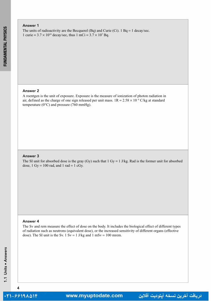
Answer 4The Sv and rem measure the effect of dose on the body. It includes the biological effect of different types of radiation such as neutrons (equivalent dose), or the increased sensitivity of different organs (effective dose). The SI unit is the Sv. 1 Sv = 1 J/kg and 1 mSv = 100 mrem.
Answer 3The SI unit for absorbed dose is the gray (Gy) such that 1 Gy = 1 J/kg. Rad is the former unit for absorbed dose, 1 Gy = 100 rad, and 1 rad = 1 cGy.
Answer 2A roentgen is the unit of exposure. Exposure is the measure of ionization of photon radiation in air, defined as the charge of one sign released per unit mass. 1R = 2.58 × 10⁻⁴ C/kg at standard temperature (0°C) and pressure (760 mmHg).
Answer 1The units of radioactivity are the Becquerel (Bq) and Curie (Ci). 1 Bq = 1 decay/sec. 1 curie = 3.7 × 10¹⁰ decay/sec, thus 1 mCi = 3.7 × 10⁷ Bq.

5
FUND
AMEN
TAL
PHYS
ICS
1.1
Uni
ts •
Que
stio
ns
Question 7What is the electromagnetic spectrum?
Question 6How does a photon’s energy relate to its frequency and wavelength?
Question 5What is the relationship between an atomic mass unit (amu) and an electron volt (eV)?
Question 8What is the SI unit of specific activity?

6
FUND
AMEN
TAL
PHYS
ICS
1.1
Uni
ts •
Ans
wer
s
Answer 8Specific activity is defined as a sample’s activity (A) divided by its mass (m). The SI unit for specific activity is Bq/kg. It can also be given in terms of Ci/g. A higher specific activity allows a smaller source to be used for radiation treatment. For example, the specific activity of 60Co source is 200 Ci/g and could contain 6,000 to 7,000 Ci in a 1.5 to 2.0 cm diameter 60Co source.
Answer 7Photons travel as electromagnetic waves, described by the electromagnetic spectrum. This spectrum defines regions based on their energy (and hence wavelength or frequency). From lowest energy (and lowest frequency, highest wavelength) the spectrum starts with radio waves, then microwaves, infrared, visible, ultraviolet, X-rays, and gamma rays.
Answer 6The energy of a photon equals its frequency (in Hz) multiplied by Planck’s constant (h = 6.26 × 10⁻³⁴ J sec). Frequency (v) is related to wavelength (l) by c = lv. The velocity (c) is the speed of light, 3 × 10⁸ m/sec.
Answer 5The electron volt is defined as the kinetic energy given to an electron initially at rest going through a potential difference of 1 V. It is a unit of energy with 1 eV = 1.602 × 10⁻¹⁹ Joules (J) and 1 amu = 931 MeV. The amu represents one twelfth of the mass of a carbon-12 nucleus.

7
FUND
AMEN
TAL
PHYS
ICS
1.2
Ato
mic
and
Nuc
lear
Str
uctu
re •
Que
stio
ns
Question 9What is Planck’s constant and how is it used to calculate the energy of a photon?
Question 11What is the Avogadro constant?
Question 10What is the relationship between energy and wavelength and how can that relationship be used to calculate the energy of a photon?
Question 1 1.2 ATOMIC AND NUCLEAR STRUCTUREWhat is the charge of an electron?
8
FUND
AMEN
TAL
PHYS
ICS
1.2
Ato
mic
and
Nuc
lear
Str
uctu
re •
Ans
wer
s
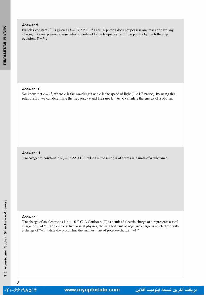
Answer 11The Avogadro constant is N
A = 6.022 × 10²³, which is the number of atoms in a mole of a substance.
Answer 10We know that c = vl, where l is the wavelength and c is the speed of light (3 × 10⁸ m/sec). By using this relationship, we can determine the frequency v and then use E = hv to calculate the energy of a photon.
Answer 9Planck’s constant (h) is given as h = 6.62 × 10⁻³⁴ J sec. A photon does not possess any mass or have any charge, but does possess energy which is related to the frequency (v) of the photon by the following equation, E = hv.
Answer 1The charge of an electron is 1.6 × 10⁻¹⁹ C. A Coulomb (C) is a unit of electric charge and represents a total charge of 6.24 × 10¹⁸ electrons. In classical physics, the smallest unit of negative charge is an electron with a charge of “−1” while the proton has the smallest unit of positive charge, “+1.”

9
1.2
Ato
mic
and
Nuc
lear
Str
uctu
re •
Que
stio
ns
Question 4What is the charge and mass (MeV) of an electron, proton, and neutron?
Question 3What is the maximum number of electrons that can be placed in a shell?
Question 2What is the binding energy of an electron?
Question 5For an atom designated by the following atomic symbol: AZ X, how does one determine the atomic mass number, the number of protons, electrons, and neutrons in the atom as well as the number of nucleons?
FUND
AMEN
TAL
PHYS
ICS

10
FUND
AMEN
TAL
PHYS
ICS
1.2
Ato
mic
and
Nuc
lear
Str
uctu
re •
Ans
wer
s
Answer 4An electron has a charge of −1 and a rest mass of 0.511 MeV. The mass of an electron is 1/1,836 compared to the mass of a proton. The proton has a charge of +1, and a rest mass of 938 MeV. The neutron has a charge of 0, and a rest mass of 939 MeV.
Answer 3Electron shells are labeled starting from the inner most shell by letters or by numbers. The inner most shell is the “K Shell” followed by the L, M, and N shells, respectively. The maximum number of electrons that can be allowed in a shell is 2n2, where n is the shell number from the inner most to outer most orbital, (K = 1, L = 2). However, the outer most shell of an atom commonly referred to as the valance shell is only able to carry eight electrons.
Answer 2The electron binding energy is determined by the Coulomb attraction between the nucleus (protons) and orbital electrons (e−). The electron binding energy increases as Z increases and decreases as the distance from the nucleus increases. The binding energy of an electron is the minimum energy required to knock the electron out of the atom.
Answer 5For a given atomic symbol, the number of protons is equal to “Z” which is also equal to the number of electrons. “A” is the mass number which is also equal to the number of protons + neutrons and is also referred to as the number of nucleons. The number of neutrons is equal to A – Z.

11
FUND
AMEN
TAL
PHYS
ICS
Question 8What is a characteristic X-ray?
Question 7What is an isotope, isotone, isobar, and isomer?
Question 6Arrange the following forces (weak force, strong force, gravitational force, and electromagnetic force) in order from weakest to strongest and describe their basic responsibilities.
1.2
Ato
mic
and
Nuc
lear
Str
uctu
re •
Que
stio
ns
Question 9What is an Auger electron?

12
FUND
AMEN
TAL
PHYS
ICS
Answer 8If an atom is ionized, a vacancy may be created in an inner electron orbital. An electron in an outer orbital will then fill the vacancy and a photon with energy equal to the difference in energy of the two orbitals is created. This energy is characteristic of the particular element involved (hence the name).
Answer 7An element is defined by its atomic number Z, which represents the number of protons, and gives the element its chemical properties. The same element can have differing numbers of neutrons but the same number of protons, these are referred to as isotopes. An isotone is the opposite, they are nuclei with the same number of neutrons, but different numbers of protons. Isobars are nuclei that have the same number of nucleons (eg, seven protons and eight neutrons, or six protons and nine neutrons), that is the same atomic number. A helpful guide is istoPes have equal number of Protons, isotoNes have equal Neutrons, and isobArs have same atomic weight (A). An isomer is the same nucleus (the same number of protons, neutrons, and the same atomic number) but is an excited, usually unstable state of the nucleus.
Answer 6The weakest is the gravitational force which is the force that attracts masses, but on the scale of the atomic world it is negligible. Next, the weak force is responsible for nuclear decay. The electromagnetic force exists between all particles which have an electric charge. The strong force is responsible for binding nuclei and exists over a very short range.
1.2
Ato
mic
and
Nuc
lear
Str
uctu
re •
Ans
wer
s
Answer 9An Auger electron is an alternative and competing process to characteristic X-rays that can sometimes occur. Here, instead of a characteristic X-ray escaping the atom, it hits another orbiting electron, which is ejected from the atom. This is known as an Auger electron.

13
FUND
AMEN
TAL
PHYS
ICS
Question 12What is the fluorescent yield?
Question 11Why do fission and fusion occur?
Question 10What is the difference between fission and fusion?
1.2
Ato
mic
and
Nuc
lear
Str
uctu
re •
Que
stio
ns
Question 13What is the difference between an X-ray and a gamma ray?

14
FUND
AMEN
TAL
PHYS
ICS
Answer 12The fluorescent yield w is defined as the probability that an atom will yield characteristic radiation rather than an Auger electron. The following relationships are noted:High-Z → large w → emission of characteristic radiation more probableLow-Z → small w → emission of Auger electrons more probable.
Answer 11The binding energy per nucleon has a maximum near A = 56, and the average binding energy (except for light elements) is about 8 MeV per nucleon. Both fission (for A >56) and fusion (for A <56) occur to enable nuclei to approach a more stable state that is closer to the maximum binding energy per nucleon.
Answer 10Fission is the splitting of a large unstable nucleus into more stable pieces. Fusion combines two or more lighter nuclei into one, as occurs in the sun when hydrogen is fused to form helium.
1.2
Ato
mic
and
Nuc
lear
Str
uctu
re •
Ans
wer
s
Answer 13X-rays and gamma rays are both photons and forms of electromagnetic energy but gamma rays are defined as being of nuclear origin, and X-rays of atomic origin.

15
FUND
AMEN
TAL
PHYS
ICS
1.3
Rad
ioac
tivi
ty •
Que
stio
ns
Question 14What are the two competing mechanisms by which the nucleus can release excess energy in isomeric transition?
Question 1 1.3 RADIOACTIVITYHow is the decay constant of a nucleus related to its half-life?
Question 2Describe the type of equilibrium that can occur with radioactive decay when the decay constant of the daughter is much greater than the parent decay constant?
Question 3What are the two types of decay that tend to occur in nuclei that have a low neutron to proton (n/p) ratio?

16
FUND
AMEN
TAL
PHYS
ICS
1.3
Rad
ioac
tivi
ty •
Ans
wer
s
Answer 14An isomeric transition means the nucleus is changing energy states, without changing the number of protons and neutrons within it. One way the nucleus can release energy is called gamma emission. In gamma emission, the nucleus releases excess energy by the direct emission of one or more gamma rays from the nucleus. An alternative method of releasing energy is internal conversion where one or more of the orbital electrons is emitted. If an inner shell electron is emitted, shell filling will occur and will result in characteristic X-rays and/or Auger electrons being released.
Answer 2This type of equilibrium is called secular equilibrium. This is characterized by a gradual buildup of activity of the daughter until it reaches the level of the parent. After secular equilibrium has been established, the activity of the daughter is approximately equal to the activity of the parent. This is the case for Radium and its daughter Radon. The decay constant is inversely proportional to the half-life, so for secular equilibrium, the daughter half-life must be much shorter than the parent. If the decay constant of the daughter is greater than the decay constant of the parent but not much greater, then transient equilibrium is achieved. In transient equilibrium, there is an initial buildup of the daughter until it eventually exceeds the activity of the parent. After that point, the activity of the daughter follows the activity of the parent, always exceeding the parent by a small amount. This is exemplified by Mo-99 (molybdenum) and its daughter Tc-99m (Technetium).
Answer 1The decay constant is related to the half-life: l = ln(2)/ 1/2T
Answer 3Radionuclides that have a low n/p ratio tend to increase the ratio by converting a proton into a neutron. In beta plus decay or positron emission, the proton converts into a neutron emitting a positive electron (positron or beta plus) and a neutrino.
A competing process with beta plus decay is electron capture. Here, one of the inner orbital electrons (usually K shell) is captured by the nucleus. The nucleus rearranges and transforms a proton into a neutron to reach a new stable state. After an electron is captured by the nucleus in electron capture decay, characteristic X-rays or Auger electrons will be produced.

17
FUND
AMEN
TAL
PHYS
ICSQuestion 4
Describe the differences in the neutron to proton ratio (n/p) with respect to the atomic number of the nucleus?
Question 6What is isobaric decay?
Question 5What is isomeric transition?
1.3
Rad
ioac
tivi
ty •
Que
stio
ns
Question 7What is the nuclear binding energy?
18
FUND
AMEN
TAL
PHYS
ICS Answer 4
For atomic elements where Z is less than or equal to 20, the ratio of neutrons to protons is 1. If Z is greater than 20, the ratio increases with Z. The additional neutrons are needed to help keep the nuclei stable and to compensate for electrostatic repulsion between the protons.
Answer 6Isobaric decay is any radioactive decay in which the original (or parent) nucleus and the new (or daughter) nucleus contains the same number of total nucleons (protons + neutrons). When this occurs, the parent nucleus and the daughter nucleus are referred to as isobars of one another. Both types of beta decay are isobaric.
Answer 5Isomeric transition occurs when a previous radioactive decay leaves the daughter nucleus in a metastable state which then transitions to the ground state. The daughter nucleus stays in an excited state for a short period of time. The only difference between the metastable state and the final stable ground state is an energy difference, thus the two states are called isomers. An example of this is technetium-99m. Molybdenum-99 decays via beta decay to Tc-99m. In this metastable state, it has a half-life of 6 hours. It then decays via gamma emission, releasing a photon of 141 keV, which is used for imaging in single-photon emission computed tomography (SPECT).
1.3
Rad
ioac
tivi
ty •
Ans
wer
s
Answer 7The nucleus is made up of protons and neutrons, but the mass of the nucleus will always be less than the sum of the individual masses of the protons and neutrons which constitute it. The deficiency of mass is called the mass defect, and the energy that is required to separate the nucleus into its constituent particles is called the binding energy of the nucleus and is given by Einstein’s famous equation: E = ∆mc2. The ∆m is the mass difference of the nucleus and its constituent particles (protons + neutrons).

19
FUND
AMEN
TAL
PHYS
ICSQuestion 8
What are the two types of beta decay? Describe beta decay in general.
Question 10What is beta plus decay?
Question 9What is beta minus decay?
1.3
Rad
ioac
tivi
ty •
Que
stio
ns
Question 11What is a competing process to beta plus decay?

20
FUND
AMEN
TAL
PHYS
ICS Answer 8
The two types of beta decay are beta minus decay and beta plus decay. Beta decay is the process by which a radioactive nucleus ejects either a negatively charged electron (beta minus or β−) or positively charged positron (beta plus or β+). An electron that is ejected is differentiated from an orbital electron by using the β− term instead of “e” which refers to an orbital electron. Both forms of beta decay are isobaric as the total atomic number does not change.
Answer 10Beta plus decay is also known as positron emission and occurs when a radionuclide has a low neutron to proton ratio (n/p) ratio. In beta plus decay, a proton (p) is converted into a positron (also known as a β+ particle), a neutron (n), and neutrino (v). The general equation for beta plus decay is:
p → n + β+ + v
In beta plus decay, there is a decrease in the atomic number of the daughter element by one. After a beta plus particle is produced, it will eventually interact with an electron causing both particles to be annihilated, producing two photons (gamma rays) that each have energy of 0.511 MeV and travel in opposite directions. Because of this, there is a threshold in the difference between the parent and daughter binding energy of 1.02 MeV for a radionuclide to undergo positron emission.
Answer 9In beta minus decay, a neutron is converted into an electron (also known as a β− particle), a proton, and anti-neutrino. This type of decay is more common with a nucleus that has an n/p ratio >1. The general equation for a beta minus decay is:
n → p + β− + v
The energy released is the difference in binding energy of the parent and daughter nucleus, minus the mass of the electron. This energy is shared as kinetic energy of the outgoing particles, with on average one third going to the β− particle, and the remainder to the anti-neutrino (v ). The anti-neutrino does not carry any electric charge, and is weakly interacting. There will be an increase in the atomic number of the daughter element by one after a particle undergoes beta minus decay.
1.3
Rad
ioac
tivi
ty •
Ans
wer
s
Answer 11A competing process to beta plus decay is electron capture. This occurs when the nucleus captures an orbital electron, typically from the K-shell and the proton is converted to a neutron (n), and neutrino (v). Electron capture does not require a threshold energy of 1.02 MeV to occur and is more prevalent for heavier elements. The general equation for electron capture is:
p + e → n + v
Because electron capture leaves an empty hole in the orbital shell, this empty hole can be filled by an outer shell electron, causing a release of a characteristic X-ray or Auger electron. Because electron capture often involves the K shell orbital electron, it is often referred to as K-capture. Similarly to beta plus decay, there will be a decrease in the atomic number of the daughter element by one after a particle undergoes electron capture.

21
FUND
AMEN
TAL
PHYS
ICS
1.4
Exp
one
ntia
l Dec
ay •
Que
stio
ns
Question 12What is alpha decay, and describe which radionuclides typically undergo alpha decay?
Question 13If an isotope 105
220 A decays by α decay and then β− decay, what is the atomic number and weight of the new element?
Question 1 1.4 EXPONENTIAL DECAYWhat is the decay constant?
Question 2What is the time required for either the activity or the number of radioactive atoms to decay to half of the initial value?

22
FUND
AMEN
TAL
PHYS
ICS
1.4
Exp
one
ntia
l Dec
ay •
Ans
wer
s
Answer 12Alpha decay is a type of radioactive decay where a nucleus emits an alpha particle. An alpha particle has the same nuclear structure as a helium nucleus. An alpha particle is usually designated by the symbol 4
2 He.
Radionuclides that have a high-Z (usually Z >82) decay most frequently by the emission of an alpha particle. An example of alpha decay is when radium (Ra) undergoes decay to radon (Rn): 88
226 Ra Æ 86222 Rn + 2
4 He + Energy.
Answer 13Initial atomic weight is 220, α decay reduces this by 4, β− decay does not change the number of nucleons. Therefore, the final atomic weight is 216.The initial atomic number is 105, α decay reduces this by 2, β− decay increases this by 1, so the final atomic number is 104. The new element is 104
216 B.
Answer 1The decay constant, l, is a proportionality constant that relates the number of radioactive atom disintegrations per unit time to the number of atoms present. The relationship between the number of remaining atoms (N), to the number of initial atoms (N
0) is related by the exponential equation:
N = N0e−lt
Alternatively this can be written using A as the current activity, and A0 as the initial activity.
Answer 2This is the definition of half-life. (Half-Life) 1/2T = ln(2)/l = (0.693)/l. After n half-lives, the activity or number of radioactive atoms is reduced to ½n of the initial value.

23
FUND
AMEN
TAL
PHYS
ICS
Question 4What is the specific activity of a radionuclide?
Question 3What is the average lifetime?
1.4
Exp
one
ntia
l Dec
ay •
Que
stio
nsQuestion 5The initial activity of an unknown element is 3 Ci. After 12 days, the activity is 2.61 Ci. What is the half-life? What might the element be?
24
FUND
AMEN
TAL
PHYS
ICS Answer 3
The average or mean lifetime is the average length of time a radioactive atom remains in its sample. Average lifetime (T ) equals 1.44 × the half-life ( 1/2T ). It is also equivalent to the length of time a sample would take to decay if it continued to decay at its initial decay rate. As such it is useful in calculating dose delivered by permanent implants.
Answer 4The specific activity of a radionuclide is defined to be its activity per unit mass. The specific activity is independent of the mass of the radionuclide, and has a fixed value independent of the time. The units of specific activity are Ci/g or Bq/kg.
1.4
Exp
one
ntia
l Dec
ay •
Ans
wer
s
Answer 5Use the following formula: A A e t T
00.693 / 1/ 2= −
2.61 = 3 e T0.693 12/ 1/ 2− ×
ln(2.61/3) = −0.693 × 12/ 1/2T
−0.139 = −8.316/ 1/2T
1/2T = 8.316/0.139
1/2T = 59.7 days
This is approximately the half-life of I-125. An alternative formula is:
Tt
A
A
0.693
ln1/2
0
= −

25
FUND
AMEN
TAL
PHYS
ICS
Question 7What is the approximate amount of activity remaining after 1, 2, 3, 4, 5, and 10 half-lives?
1.4
Exp
one
ntia
l Dec
ay •
Que
stio
ns
Question 6What is the decay constant of I-125?
Question 8The initial dose rate of a prostate implant is 7 cGy/hr using I-125 seeds. What is the total dose the prostate will receive?
Question 9If the initial activity of a new source of Ir-192 for high dose rate (HDR) is about 9.98 Ci, what is the source activity in GBq in three months (90 days) later, given the half-life of Ir-192 is 74 days?
26
FUND
AMEN
TAL
PHYS
ICS
Answer 7After n half-lives, the activity A = A
0 ½n, so
Half-lives 1 2 3 4 5 10
% remaining 50% 25% 12.5% 6.25% 3.125% ~0.1%
These numbers are also relevant when considering the radiation penetrating through n half-value layers of material.
Answer 6The half-life of I-125 is 59.4 days.
ln T2 / 1/2λ =
0.693
59.4λ =
d0.0117 1= −
1.4
Exp
one
ntia
l Dec
ay •
Ans
wer
s
Answer 8Use the average life of I-125 = 1.44 1/2T = 85.5 days
Dose = initial dose rate × average life
= 7 cGy/hr × 85.5 days × 24 hr/day
= 14,370 cGy.
Answer 9Use the formula:
A = 9.98 e 0.693 90/74− ×
A = 9.98 e 0.843−
A = 4.30 Ci
= 4.3 × 37 GBq/Ci
= 159 GBq.
A A e t T0
0.693 / 1/ 2= −

27
FUND
AMEN
TAL
PHYS
ICS
Question 11An high dose rate (HDR) treatment using Ir-192 takes 281 seconds. How long will it take to complete when the patient returns next week for the second fraction?
Question 10Express the activity formula in terms of number of half-lives and use it to answer the previous question.
1.4
Exp
one
ntia
l Dec
ay •
Que
stio
ns
Question 12What is the activity of a 30 mCi I-125 prostate implant after one year?
Question 13A source decays 3% in one day. What is the decrease in activity after 30 days?
Question 14An Ir-192 high dose rate (HDR) source must have an activity of 10 Ci when it is installed in the afterloader. What activity should it have one week earlier when it is calibrated to ensure this?

28
FUND
AMEN
TAL
PHYS
ICS
Answer 11After seven days, the activity of the source has been reduced by ½7/74 or 6.3%. The treatment time must be increased by this amount, 281 × 1.063 = 299 sec.
Answer 10The activity formula A A e t T
00.693 / 1/ 2= − can be rewritten as:
A An1
20=
where n = t/ 1/2T is the number of half-lives. This makes the calculation of activity much simpler.
Now, A = 9.98 (½)90/74
= 9.98 0.51.216
= 4.30 Ci
1.4
Exp
one
ntia
l Dec
ay •
Ans
wer
s
Answer 12
A = 30½365/59.4
= 0.42 mCi.
Answer 13First determine the half-life or decay constant.
0.693
ln1/2
0
Tt
A
A
= −
T0.693 1
ln0.971/2 = −
1/2T = 22.75 days.
A/A0 = ½30/22.75
= 0.40So the source activity has decreased by 60% after 30 days.
Answer 14
A An1
20=
Ci A101
20
7/74
=
A 10 /1
20
7/74
=
A0 = 10.68 Ci is the activity required at the time of calibration, seven days before.

2.1 Production of X-rays 31
2.2 LinEar accELErators 41
2.3 ParticLE and sourcE-BasEd
radiation 51
2RADIATION GENERATING EQUIPMENT
Qingyang shang and MatthEW KoLar

31
RADI
ATIO
N GE
NERA
TING
EQU
IPM
ENT
2.1
Pro
duc
tio
n o
f X
-ray
s •
Que
stio
ns
Question 3What is the energy spectrum of bremsstrahlung and characteristic X-rays?
Question 2Describe how bremsstrahlung and characteristic X-rays are produced.
Question 1 2.1 Production of X-raysWhat are the two different mechanisms by which X-rays are produced?
Turn page to see the answers.

32
RADI
ATIO
N GE
NERA
TING
EQU
IPM
ENT
2.1
Pro
duc
tio
n o
f X
-ray
s •
Ans
wer
s
answer 3Bremsstrahlung X-rays have a spectrum of energies. The maximum X-ray energy is equal to the energy of the incident electron. The energy of the electron corresponds to the peak accelerating voltage. The most probable X-ray energy is about one third of the maximum energy.
Characteristic X-rays have discrete energies, corresponding to the energy level difference between atomic shells involved in the electron transition.
X-ray photons produced by an X-ray tube are the combination of the two. It has a continuous distribution of energies for the bremsstrahlung photons superimposed with characteristic radiation at discrete energies.
answer 2Bremsstrahlung X-rays result from the Coulomb interaction between the incident electron and the nuclei of the target material. The incident electron is decelerated, losing kinetic energy in the form of bremsstrahlung photons (radiative loss).
Characteristic X-rays result from Coulomb interactions between the incident electrons and atomic orbital electrons of the target material (collision loss). The orbital electron is ejected from its shell and an electron from a higher level shell fills the vacancy. The energy difference between the two shells may either be emitted from the atom in the form of a characteristic photon (characteristic X-ray) or transferred to another orbital electron that is ejected from the atom as an Auger electron.
answer 1X-rays are produced by bremsstrahlung and characteristic X-ray emission. Useful X-ray beams in imaging and therapy are typically all bremsstrahlung, except in mammography where characteristic X-rays are desirable.
Num
ber o
f X-ra
ys
X-ray Energy
Maximumenergy
Characteristic X-rays
Bremsstrahlung X-rays

33
RADI
ATIO
N GE
NERA
TING
EQU
IPM
ENT
2.1
Pro
duc
tio
n o
f X
-ray
s •
Que
stio
ns
Question 5Relative to the incoming electron beam, at what angle are bremsstrahlung X-rays produced?
Question 4What is the classification of therapy X-ray beams?
Question 6How does fluorescent yield change with Z?
Question 7How efficient is X-ray production?
34
RADI
ATIO
N GE
NERA
TING
EQU
IPM
ENT
2.1
Pro
duc
tio
n o
f X
-ray
s •
Ans
wer
s
answer 6The fluorescent yield ω gives the ratio of fluorescent (characteristic) photons emitted per vacancy in a shell to the number of Auger electrons. It ranges from zero for low-Z atoms through 0.5 for copper (Z = 29) to 0.96 for high-Z atoms with K shell vacancies, which are the most prominent sources of characteristic X-rays.
answer 5In the kilovoltage energy range, X-rays are produced uniformly with regards to direction, shielding around the target produces an X-ray beam at 90°. In the megavoltage energy range (1–50 MV) most photons are produced in the direction of electron acceleration (forward direction 0°).
answer 4X-rays used in radiation oncology are usually classified as:
(a) Grenz ray therapy: treatment that uses very low energy (below 20 kV) X-rays. No longer in use.(b) Contact therapy: operates at 40 to 50 kV and facilitates irradiation of accessible lesions at very short
source to surface distance (SSD) (2 cm or less). A filter of 0.5- to 1.0-mm-thick aluminum is usually interposed in the beam to abs orb the very soft component of the energy spectrum. It is useful for tumors not deeper than 1 to 2 mm.
(c) Superficial therapy: treatment with X-rays ranging from 50 to 150 kV. Varying thicknesses of filtration (usually 1–6 mm aluminum) are added to harden the beam to a desired degree. The SSD typically ranges between 15 and 20 cm. Useful for irradiating tumors confined to about 5 mm depth.
(d) Orthovoltage therapy: treatment with X-rays ranging from 150 to 500 kV, and filtered with 1 to 4 mm copper. The SSD is typically 50 cm. Useful for tumor less than 2 to 3 cm deep.
(e) Supervoltage therapy: X-ray therapy in the range of 500 to 1,000 kV, filtered with 4 to 6 mm copper.
In contrast, diagnostic X-rays are usually in the 10 to 150 kV range.
answer 7Efficiency of X-ray production is proportional to the atomic number (Z) of target and energy of the electrons. Efficiency is less than 1% for X-ray tubes operating at 100 kVp (99% of input energy is converted into heat). Efficiency improves considerably for megavoltage accelerator beams (30%–95%, depending upon energy).

35
RADI
ATIO
N GE
NERA
TING
EQU
IPM
ENT
2.1
Pro
duc
tio
n o
f X
-ray
s •
Que
stio
ns
Question 10What are thin and thick targets, respectively, for an X-ray tube?
Question 9Why is tungsten the chosen material for the cathode and anode of an X-ray tube?
Question 11What is the purpose of the added filtration placed externally to the X-ray tube?
Question 8What are the components of a typical X-ray tube?
36
RADI
ATIO
N GE
NERA
TING
EQU
IPM
ENT
2.1
Pro
duc
tio
n o
f X
-ray
s •
Ans
wer
s
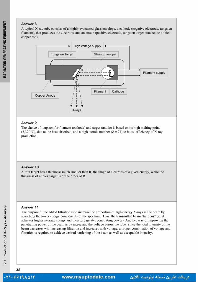
answer 10A thin target has a thickness much smaller than R, the range of electrons of a given energy, while the thickness of a thick target is of the order of R.
answer 9The choice of tungsten for filament (cathode) and target (anode) is based on its high melting point (3,370°C), due to the heat absorbed, and a high atomic number (Z = 74) to boost efficiency of X-ray production.
answer 8A typical X-ray tube consists of a highly evacuated glass envelope, a cathode (negative electrode, tungsten filament), that produces the electrons, and an anode (positive electrode, tungsten target attached to a thick copper rod).
High voltage supply
Tungsten Target Glass Envelope
Filament supply
Copper AnodeFilament Cathode
X-rays
answer 11The purpose of the added filtration is to increase the proportion of high-energy X-rays in the beam by absorbing the lower energy components of the spectrum. Thus, the transmitted beam “hardens” (ie, it achieves higher average energy and therefore greater penetrating power). Another way of improving the penetrating power of the beam is by increasing the voltage across the tube. Since the total intensity of the beam decreases with increasing filtration and increases with voltage, a proper combination of voltage and filtration is required to achieve desired hardening of the beam as well as acceptable intensity.

37
RADI
ATIO
N GE
NERA
TING
EQU
IPM
ENT
2.1
Pro
duc
tio
n o
f X
-ray
s •
Que
stio
nsQuestion 15What is heel effect?
Question 14What is beam hardening?
Question 13If a 2 mm thickness of material transmits 25% of a monoenergetic beam of photons, calculate the half-value layer (HVL) and μ of the beam.
Question 12What is half-value layer (HVL)?

38
RADI
ATIO
N GE
NERA
TING
EQU
IPM
ENT
2.1
Pro
duc
tio
n o
f X
-ray
s •
Ans
wer
s
answer 14The lower energy photons of the polyenergetic X-ray beam will be preferentially removed from the beam while passing through matter. The shift of the X-ray spectrum to higher effective energies as the beam transverses matter is called beam hardening. For polyenergetic beams, this causes the second half-value layer (HVL) to be greater than the first HVL.
answer 13
= −µI I e0L
0.25 e 0.2 cm= −µ ×
µ = − = −ln0.25
0.2 cm6.93 cm 1
=µ
=HVL0.693
0.1 cm
answer 12HVL is defined as the thickness of material required to reduce the intensity of a beam to one half of its initial value. A related quantity is the linear attenuation coefficient μ, where HVL = 0.693/μ.
answer 15Since the X-rays are produced at various depths in the target, they suffer varying amounts of attenuation in the target. There is greater attenuation for X-rays coming from greater depths than those from near the surface of the target. Consequently, the intensity of the X-ray beam decreases from the cathode to the anode direction of the beam. This variation across the X-ray beam is called the heel effect. The effect is particularly pronounced in diagnostic tubes because of the low X-ray energy and steep target angles. The problem can be minimized by using a compensating filter to provide differential attenuation across the beam to compensate for the heel effect and improve the uniformity of the beam.

39
RADI
ATIO
N GE
NERA
TING
EQU
IPM
ENT
2.1
Pro
duc
tio
n o
f X
-ray
s •
Que
stio
ns
Question 19What is the difference between tube current and filament current?
Question 18For an X-ray beam, what is inherent filtration?
Question 17The actual anode focal area for a 20° anode angle is 4 mm (length) by 1.2 mm (width). What is the projected focal spot size at the central axis?
Question 16What are dual focal spots?
Question 20How do tube current (mA) and tube voltage (kVp) affect X-ray intensity?

40
RADI
ATIO
N GE
NERA
TING
EQU
IPM
ENT
2.1
Pro
duc
tio
n o
f X
-ray
s •
Ans
wer
s
answer 18All X-ray beams have some filtration; this is typically from absorption in the target, the wall of the tube and air. This is referred to as inherent filtration.
answer 17An angled target is used to reduce the effective size of the focal spot. The effective focal spot width is equal to the actual focal spot width since it is unaffected by the angle of the anode. The effective focal spot length = actual focal spot length × sin θ, where θ is the anode angle.
So for this problem, effective length = 4 mm × sin 20 = 1.36 mm.
Effective focal spot size = 1.36 mm × 1.2 mm = 1.632 mm2
Thus, a large electron beam can be used, to spread the heat on the target, but a small focal spot can be produced for sharp images.
answer 16The size of the target area from which the X-rays are emitted is called the focal spot. The size of the focal spot depends on the size of the tungsten filament of the cathode. In diagnostic radiology, the focal spot should be as small as possible to produce sharp radiographic images. But smaller focal spots generate more heat per unit area of target and thus limit currents and exposure. Diagnostic tubes usually have two separate filaments to provide “dual focus,” a small and large filament for small and large images.
answer 19Filament current is the flow of electrons through the filament. Thermionic emission happens when the filament current is sufficient for electrons to be boiled off and directed toward the anode. Filament current is on the order of amperes (A).
Tube current is the flow of electrons from the cathode to the anode. It is controlled by filament current. A small change in filament current results in an exponential change in tube current. It is on the order of milliampere.
answer 20The tube current (mA) is equal to the number of electrons flowing from the cathode to the anode per unit time. Increasing tube current will increase the quantity of electrons available to hit the target, and that results in an increase of X-ray photons produced. Beam on time (seconds) also increases quantity, the combination is mAs.
The tube voltage (kVp) determines the maximum energy in the bremsstrahlung spectrum and affects the quality of the beam. It also affects the efficiency of the X-ray production, which is the number of X-ray photons produced per unit time (quantity). Beam intensity is proportional to kVp2.X-ray output is most affected by filament current.

41
RADI
ATIO
N GE
NERA
TING
EQU
IPM
ENT
2.2
Lin
ear
acc
eler
ato
rs •
Que
stio
ns
Question 1 2.2 LinEar accELEratorsHow does the flattening filter affect the photon beam?
Question 2What changes are made to switch from photon mode to electron mode in a linear accelerator (linac)?
Question 3How does an electron gun work?
Question 4Why is a bending magnet used in a linear accelerator (linac)?
Question 5Explain the term isocenter.
42
RADI
ATIO
N GE
NERA
TING
EQU
IPM
ENT
2.2
Lin
ear
acc
eler
ato
rs •
Ans
wer
s
answer 1The flattening filter is used in photon beams to create a flat dose profile at a depth of 10 cm in water. Without it, the beam profile is very peaked. The flattening filter produces horns at the beam edges at shallower depths. It is typically a conical piece of high-Z material. Due to its introduction to the beam, it increases the effective energy of the beam, by filtering out low energy photons (beam hardening) but it decreases the beam intensity and thus the dose rate.
answer 2In electron mode, the target and flattening filter are removed. A scattering foil is added to create a broad, flat beam. An electron applicator is used to collimate the beam by removing the scatter in air. The accelerated beam current is much lower in electron mode, as there is no loss in efficiency as seen in photon mode due to the presence of the target and flattening filter.
answer 3An electron gun is a simple electrostatic accelerator containing a heated cathode filament and a perforated grounded anode. A hot cathode emits electrons, which are accelerated toward an anode, passing through an aperture to reach the accelerating waveguide. Along this path, negatively charged focusing electrodes narrow the electrons into a fine beam which then passes through the aperture in the anode. A grid allows for synchronization of electron release into the accelerating waveguide to match its phase.
answer 4The bending magnet redirects accelerated electrons toward the isocenter. Using just a 90° bending magnet in the design of a linac allows the accelerator to be oriented parallel to the floor so it can more easily rotate around its isocenter without hitting the ceiling, floor or patient. Using a 270° bending magnet, also allows the energy of electrons to be selected and the electron beam to be focused, thus improving the penumbra of the beam.
answer 5Modern linear accelerators (linacs) are constructed so that the axis of gantry rotation, collimator rotation, and table rotation are coincident at one point in space called the isocenter. This allows for a patient to be treated with the isocenter within the target, and have the linac rotate around the patient. Multiple treatment beams can be delivered from various angles without having to the move the patient for each beam.

43
RADI
ATIO
N GE
NERA
TING
EQU
IPM
ENT
2.2
Lin
ear
acc
eler
ato
rs •
Que
stio
ns
Question 6What is the function of the monitor chamber in a linear accelerator (linac)?
Question 7What is the advantage of a standing wave over a traveling wave accelerating waveguide?
Question 8Why is sulfur hexafluoride, SF
6 used in a linear accelerator (linac)?
Question 9What frequency is the accelerating power source for a linear accelerator (linac)?
Question 10What is a klystron?

44
RADI
ATIO
N GE
NERA
TING
EQU
IPM
ENT
2.2
Lin
ear
acc
eler
ato
rs •
Ans
wer
s
answer 7Standing wave accelerating waveguides are more efficient and shorter than equivalent traveling waveguides. To create a standing wave, the microwaves are reflected at the end, rather than exiting the waveguide. This generates a superposition of the waves in every second cavity, providing double the accelerating power of a traveling wave cavity. The interleaving cavities, where the reflected microwaves cancel are shifted to the side of the electron path as they do not provide any acceleration. Thus, the accelerating power is increased, and the waveguide is shortened.
answer 6It monitors the output of the linac. During linac calibration, charge collected in these ion chambers (represented by monitor units) is correlated to delivered dose. Monitor chambers are then able to turn off the beam once the desired dose has been delivered. Multiple or split chambers are also used to track the flatness and symmetry of the beam.
answer 9A linac uses microwaves at 3,000 MHz or 3 GHZ. These are called S-band microwaves. Some more compact accelerators, such as CyberKnife, use X-band microwaves around 10 GHz. The size of the waveguide depends on the wavelength of the microwave, so a higher frequency implies a shorter waveguide.
answer 8SF
6 is a dielectric and prevents arcing within the transmission waveguide which guides the microwaves
from their source to the accelerating waveguide.
answer 10A klystron amplifies low power microwaves into high power microwaves. As electrons are sent though a drift tube, their velocity is modulated by the alternating electric field at the frequency of the entrant low power microwaves, creating “bunches” of electrons. The bunches induce charges on the end cavity, creating higher power microwaves at the same frequency.

45
RADI
ATIO
N GE
NERA
TING
EQU
IPM
ENT
2.2
Lin
ear
acc
eler
ato
rs •
Que
stio
ns
Question 11What is a magnetron?
Question 12What is the order of components in the head of a linear accelerator (linac)?
Question 13How would you describe the TomoTherapy system?
Question 14How would you describe the CyberKnife system?
Question 15How would you describe the Mobetron?
46
RADI
ATIO
N GE
NERA
TING
EQU
IPM
ENT
2.2
Lin
ear
acc
eler
ato
rs •
Ans
wer
s
answer 11A magnetron is a microwave generator. It has a circular structure with a cathode at the center and an anode at the outer surface made up of resonant cavities. Electrons are produced at the cathode and are subjected to an electric field between the anode and cathode. A static magnetic field is applied perpendicular to the electric field and motion of the electrons. The electrons move in spirals toward the cavities, creating microwave power, which is then sent to the accelerating waveguide.
answer 13It is an integrated system with a 6 MV linac mounted in a CT-like ring gantry. An MVCT can be acquired in the treatment position prior to treatment.
answer 12The electron beam exits the accelerating waveguide and then is bent by the magnet toward the target. The X-ray beam from the target is shaped by the primary collimator and then the flattening filter, measured by the monitor chamber, and then further shaped by the secondary collimators and multileaf collimators (MLCs).
answer 14CyberKnife features a 6 MV linear accelerator (linac) mounted on an industrial robotic arm. It can position the linac to direct treatment beams from many non-coplanar angles. It also has image guidance (stereoscopic kV and infra-red surface tracking) that continuously monitors the patient's position throughout the treatment process.
answer 15The Mobetron is a portable compact electron linear accelerator that is used for intraoperative radiation therapy (IORT). It is self-shielding so it can be used in any operating room. Its treatment energies are 6, 9, or 12 MeV. Because of its short, 50 cm source to surface distance (SSD), the dose rate is quite high (1,000 cGy/min). This leads to short treatment times.

47
RADI
ATIO
N GE
NERA
TING
EQU
IPM
ENT
2.2
Lin
ear
acc
eler
ato
rs •
Que
stio
ns
Question 16The Zeiss intrabeam is a device used for intraoperative radiation therapy (IORT). How are its photons generated?
Question 17What are some advantages of using a flattening filter free treatment beam?
Question 18What are the disadvantages of using a flattening filter free treatment beam?
Question 19How is the wedge angle defined for a physical wedge?
Question 20How is a wedge transmission factor defined for a physical wedge?

48
RADI
ATIO
N GE
NERA
TING
EQU
IPM
ENT
2.2
Lin
ear
acc
eler
ato
rs •
Ans
wer
s
answer 16The electron gun injects electrons into the accelerator with a maximum voltage of 50 kV. The electrons are directed to a gold target which is placed at the center of a spherical acrylic applicator. X-rays of approximately 20 keV are emitted isotropically.
answer 17The dose rate can be three to five times higher, which results in faster treatments. The absence of a flattening filter significantly reduces the amount of scattered radiation. This can reduce the total body dose to the patient and also make it easier to model the beam in a treatment planning system.
answer 18The beam profile is forward peaked. The beam is only meant to treat small targets. Very large targets would require more monitor units to treat the tumor volume that is far away from the central axis. The beam is also slightly less penetrating than a flattened beam which is hardened by the presence of the flattening filter.
answer 19Wedge angle is usually defined as the angle of the 50% isodose curve with respect to the central axis at a reference depth of 10 cm.
answer 20The wedge transmission factor is defined as the ratio of the dose with the wedge present to the dose without the wedge present at a depth of 10 cm.

49
RADI
ATIO
N GE
NERA
TING
EQU
IPM
ENT
2.2
Lin
ear
acc
eler
ato
rs •
Que
stio
ns
Question 21What are the different methods for obtaining a wedged isodose distribution?
Question 22How does the inverse square law relate to absorbed dose from a linear accelerator (linac)?
Question 23A photon field is calculated for 100 cm source to surface distance (SSD). If the patient is setup at 110 cm SSD, what error would you estimate for the delivered dose?
Question 24A post-spine treatment calculation is changed from 10 cm depth and 100 cm source to surface distance (SSD) to 10 cm depth source to axis distance (SAD). How will the calculation change? Will the monitor units increase or decrease?
Question 25What is a double-focused multileaf collimator (MLC)?

50
RADI
ATIO
N GE
NERA
TING
EQU
IPM
ENT
2.2
Lin
ear
acc
eler
ato
rs •
Ans
wer
s
answer 21The Physical Wedge is a tray-mounted block of steel, placed in the accessory slot of a linear accelerator (linac). The steel is shaped like a wedge, with one end thicker than the other. The thicker end, known as the heel, modulates the beam more than the other end, the toe. Physical wedges are available in fixed, standard angles, usually 15°, 30°, 45°, and 60°.
The Universal Wedge is similar to a 60° physical wedge, but it is integrated into the head of the linac. The wedge moves in and out of the treatment beam, depending upon the desired wedge isodose angle. A 60° wedge isodose angle would require that the wedge be in the beam for the duration of the treatment field. For a lower wedge isodose angle, the wedge would move out of the treatment field for a fraction of the treatment.
The Dynamic Wedge creates a wedged isodose angle by moving the collimator jaw across the field. The wedge isodose angle can be changed by modulating the dose rate and/or changing the speed of the jaw.
The multileaf collimator (MLC) can be used with segmented fields to create any dose distribution.
answer 22The absorbed dose factor is inversely proportional to the square of the distance from the target. This is due to the divergence of the beam. Imagine a sphere around the target with radius r. The surface of the sphere is 4π r2, with all the radiation from the target passing through it. Now imagine a sphere twice as far away from the target, the same amount of radiation will pass through its surface, but the surface area is four times the size, effectively reducing the intensity at any one point by four.
answer 23Inverse Square Law: 1002/1102 = 0.83The patient would be underdosed by 17%
answer 24The SSD factor is replaced with a SAD factor and the percentage depth dose (PDD) is replaced with tissue maximum ratio (TMR). The monitor units will decrease as the patient is 10 cm closer to the source.
answer 25In a double-focused MLC, the divergence of the MLC matches that of the treatment beam in the x and y directions. In one direction, the leaves move in an arcing direction to match the leaf ends with the beam divergence. In the other direction, the divergence is matched by varying the cross-sectional width of the leaves. The leaves are made thinner at the end closer to the target. Both of these result in a sharper penumbra.

51
RADI
ATIO
N GE
NERA
TING
EQU
IPM
ENT
2.3
Par
ticl
e an
d s
our
ce-B
ased
rad
iati
on
• Q
uest
ions
Question 2How would you describe the decay scheme for cobalt-60 (Co-60)?
Question 1 2.3 ParticLE and sourcE-BasEd radiationHow long is the half-life of cobalt-60 (Co-60)?
Question 4What are some examples of electrostatic accelerators and cyclic accelerators used in medicine?
Question 3What is the difference between electrostatic and cyclic accelerators?

52
RADI
ATIO
N GE
NERA
TING
EQU
IPM
ENT
2.3
Par
ticl
e an
d s
our
ce-B
ased
rad
iati
on
• A
nsw
ers
answer 2A cobalt-60 nucleus is produced in a nuclear reactor by bombarding stable Co-59 atoms with neutrons. To decay to a stable state, the Co-60 nucleus first emits a β− particle (β− decay) and then, two gamma emissions with energies of 1.17 and 1.33 MeV are observed. The average energy of the gammas is 1.25 MeV.
Creation: → γ+ +Co Co2759
01
2760n
Decay: → β γ γ+ + +−Co Ni2760
2860
10
1 2
1/2T
answer 1The half-life 1/2T (the time required for the activity of the source to be halved) of Co-60 is 5.27 years. For practical purposes it is considered harmless and inactive after 10 half-lives. Thus, Co-60 would need to be stored safely for approximately 53 years.
answer 3In electrostatic accelerators, the particles are accelerated by a constant electrostatic field over a voltage difference. The kinetic energy that the particle can gain is limited by the maximum voltage difference of the electrostatic field.
In cyclic accelerators, the electric fields are variable and particles repeatedly pass through them. This requires increasingly strong magnetic fields or radii of curvature to keep the particles returning to the cavity.
answer 4Examples of electrostatic accelerators used in medicine are superficial and orthovoltage X-ray tubes and neutron generators. Examples of cyclic accelerators are microtrons, betatrons, cyclotrons, and synchrotrons.
53
RADI
ATIO
N GE
NERA
TING
EQU
IPM
ENT
2.3
Par
ticl
e an
d s
our
ce-B
ased
rad
iati
on
• Q
uest
ions
Question 5What are examples of megavoltage radiation therapy machines?
Question 7What is the advantage of proton and heavy charged particle radiation compared to photon and electron beams?
Question 6What is a betatron, a microtron, and a cyclotron?
Question 8How is the range for other charged particles calculated given the range of protons with the same initial velocity?
54
RADI
ATIO
N GE
NERA
TING
EQU
IPM
ENT
2.3
Par
ticl
e an
d s
our
ce-B
ased
rad
iati
on
• A
nsw
ers
answer 6Cyclotron: A circular accelerator where charged particles generated at a central source are accelerated spirally outward in a plane perpendicular to a fixed magnetic field by an alternating electrical field. A cyclotron is capable of generating particle energies of between 1 and 30 MeV.
Betatron: Developed in 1940 for the circular induction acceleration of electrons and light particles. The magnetic field guide is increased over time to keep the particles in a constant-diameter circle. Mean energy is 45 MeV (maximum energy ~300 MeV). After the advent of linear accelerators (linacs) they have not been used due to their large dimensions, high costs, and low dose rates.
Microtron: Entered clinics in 1972 as a combination of a linear accelerator, followed by magnets to bend the electrons around to re-enter the accelerator. It can produce electrons energies of up to 50 MeV. One microtron generator is used to provide electrons for more than one treatment room.
Magnetic Field Electric Field
Cyclotron Constant Alternating
Betatron Variable Vortex
Microtron Fixed Variable
answer 5Examples of clinical megavoltage machines are accelerators such as Van de Graaff generator, linear accelerator (linac), betatron, cyclotron and microtron, and teletherapy gamma ray units such as cobalt-60.
answer 7The major advantage of high-energy protons and other heavy charged particles is their characteristic dose distribution as a function of depth. As the beam traverses the tissues, the dose deposited is approximately constant with depth until near the end of the range where the dose peaks followed by a rapid falloff to zero. The region of high dose at the end of the particle range is called the Bragg peak.
answer 8The approximate range for other particles with the same initial velocity can be calculated by the following relationship:
R R M M Z Z/ / /1 2 1 2 2 1
2( ) ( )= ×
where R1 and R
2 are particle ranges, M
1 and M
2 are the masses, and Z
1 and Z
2 are the charges of the two
particles being compared. Thus, from the range energy data for protons one can calculate the range of other particles such as alphas and carbon ions.

55
RADI
ATIO
N GE
NERA
TING
EQU
IPM
ENT
2.3
Par
ticl
e an
d s
our
ce-B
ased
rad
iati
on
• Q
uest
ions
Question 9How are neutron beams produced?
Question 10How would you describe the decay scheme for radium?
Question 11How would you describe the depth dose curve of a clinical electron beam?

answer 11Surface dose is high for electron beams followed by a gradual curve up until the depth of maximum dose (d
max). The depth of maximum dose increases with increasing energy. Beyond d
max, the depth dose
decreases very rapidly. R50 is defined as the depth at which the dose deposited is half the maximum dose. Practical range or Rp, is defined as the point of intersection at which the depth dose curve is extrapolated down to the bremsstrahlung tail.
answer 10Radium decays to radon through alpha emission. An alpha particle is ejected with energy of 4.78 MeV or 4.6 MeV. The 4.6 MeV alpha particle is accompanied by a 0.18 MeV gamma ray.
→ +Ra Rn He88226
86222
24
answer 9High-energy neutron beams for radiation therapy are produced by bombarding a target with charged particles from a cyclotron or linear accelerator or in a deuterium–tritium (D–T) generator. As neutrons have no electric charge, they cannot be steered or focused. The produced neutrons travel mainly in the direction of the incoming particles. The bombarding particles are either deuterons (D) or protons hitting a target usually made of beryllium, except in the D–T generator in which tritium (T) is used as the target.
56
RADI
ATIO
N GE
NERA
TING
EQU
IPM
ENT
2.3
Par
ticl
e an
d s
our
ce-B
ased
rad
iati
on
• A
nsw
ers

3IONIZING RADIATION
ZHILEI LIU SHEN AND TOUFIK DJEMIL
3.1 PHOTON INTERACTIONS 59
3.2 PARTICLE INTERACTIONS 71

59
IONI
ZING
RAD
IATI
ON3
.1 P
hoto
n In
tera
ctio
ns •
Que
stio
nsQuestion 4What is Compton scattering?
Question 3What is the photoelectric effect?
Question 2What is Rayleigh scattering?
Question 1 3.1 PHOTON INTERACTIONSWhat are the five major types of photon interactions with matter?
Turn page to see the answers.

60
IONI
ZING
RAD
IATI
ON3
.1 P
hoto
n In
tera
ctio
ns •
Ans
wer
s Answer 4Compton scattering is a collision between a photon and a loosely bound outer shell orbital electron of an atom, resulting in a scattered photon of lower energy and an electron. This is the dominant interaction of therapeutic X-ray beams with tissue. Because the incident photon energy greatly exceeds the binding energy of the outer shell electron, the Compton interaction looks like a collision between the photon and a free electron (termed nearly free).
Answer 3In the photoelectric effect, the entire energy of the incident photon is transferred to an orbital electron, which is then ejected from the atom. The energy of the ejected electron (photoelectron) is the energy of the incident photon minus the binding energy. Characteristic X-ray or Auger electron emission will subsequently occur, filling the vacancy of the photoelectron.
Answer 2In Rayleigh scattering, the incident photon interacts with the atom as a whole, scattering off in a different direction without losing energy.
Answer 1The five major types of photon interactions with matter in order of energy threshold are (1) Rayleigh scattering, also known as coherent scattering, classical scattering, or elastic scattering; (2) photoelectric effect, also known as photoelectric absorption; (3) Compton scattering, also known as incoherent scattering, or Compton effect; (4) pair production; and (5) photodisintegration or photonuclear.

61
IONI
ZING
RAD
IATI
ON3
.1 P
hoto
n In
tera
ctio
ns •
Que
stio
nsQuestion 8Does ionization occur in Rayleigh scattering?
Question 7With one incoming photon, what are the outgoing particles produced during Rayleigh scattering, photoelectric effect, Compton scattering, and pair production, respectively?
Question 6What is photodisintegration?
Question 5What is pair production?

62
IONI
ZING
RAD
IATI
ON3
.1 P
hoto
n In
tera
ctio
ns •
Ans
wer
s Answer 8Ionization does not occur in Rayleigh scattering because electrons are not ejected.
Answer 7With one incoming photon, the outgoing particles produced by the four photon interactions are listed as follows:
Rayleigh scattering: one photonPhotoelectric effect: one electronCompton scattering: one electron and one photonPair production: one electron and one positron
Answer 6In photodisintegration, an incident photon with high energy (>7 to 10 MeV) collides with the nucleus of an atom and all of the photon’s energy gets absorbed. The nucleus then emits a neutron. This effect causes extra shielding requirements for high-energy beams.
Answer 5In pair production, the photon interacts strongly with the electromagnetic field of an atomic nucleus and gives up all of its energy to create an electron and a positron.

63
IONI
ZING
RAD
IATI
ON3
.1 P
hoto
n In
tera
ctio
ns •
Que
stio
nsQuestion 12Is Compton scattering most likely to occur with inner or outer shell electrons?
Question 11What is the dependence of pair production on atomic number (Z ) and energy (E)?
Question 10What is the dependence of Compton scattering on atomic number (Z ), energy (E), and electron density (N
e)?
Question 9What is the dependence of the photoelectric effect on atomic number (Z ) and energy (E)?

64
IONI
ZING
RAD
IATI
ON3
.1 P
hoto
n In
tera
ctio
ns •
Ans
wer
s Answer 12Compton scattering is most likely to occur with outer shell electrons.
Answer 11The probability of pair production changes with Z 2 and log(E).
Answer 10The probability of Compton scattering is independent of Z and decreases with E. Compton scattering depends on the electron density N
e of the material.
Answer 9The photoelectric effect is proportional to Z 3/E3, where Z is the atomic number of the target atom, and E is the energy of the incident photon.

65
IONI
ZING
RAD
IATI
ON3
.1 P
hoto
n In
tera
ctio
ns •
Que
stio
nsQuestion 16When is the photoelectric effect most probable with respect to the energy of the photon and the electron binding energy?
Question 15Which interaction is the main cause for the absorption in water of photons with energy 100 keV to 10 MeV?
Question 14Which interaction is the main cause for the absorption in water of photons with energy 10 to 100 keV?
Question 13What is the minimum energy of an incident photon for the pair-production process?
66
IONI
ZING
RAD
IATI
ON3
.1 P
hoto
n In
tera
ctio
ns •
Ans
wer
s Answer 16The photoelectric effect is most probable when the energy of the photon is slightly higher than the electron binding energy. In the absorption spectrum, the shell binding energies appear as sharp peaks known as “absorption edges,” labeled by the corresponding shell, for example, K-edge, for absorption from the inner most shell.
Answer 15Compton scattering is the main cause for the absorption in water of photons with energy of 100 keV–10 MeV. This is the range of therapeutic X-rays.
Answer 14Photoelectric effect is the main cause for the absorption in water of photons with energy 10 to 100 keV. This is the range of diagnostic X-rays. The dependence of the absorption on atomic number Z 3 provides the excellent contrast of diagnostic X-ray images.
Answer 13The minimum energy of an incident photon for the pair-production process is 1.02 MeV. This energy corresponds to the mass of the electron and positron produced (0.511 MeV each). Additional energy above the 1.02 MeV threshold is carried away as kinetic energy by the pair.
67
IONI
ZING
RAD
IATI
ON3
.1 P
hoto
n In
tera
ctio
ns •
Que
stio
ns
Question 20In Compton scattering, as the incident photon energy increases, are the photons and electrons scattered more toward the forward or backward direction?
Question 19In Compton scattering, a 6 MeV incident photon scatters to 60°, what is the energy of the ejected Compton electron?
Question 18At what energy are the probabilities of Compton scattering and photoelectric effect about the same for soft tissue?
Question 17What is KERMA?

68
IONI
ZING
RAD
IATI
ON3
.1 P
hoto
n In
tera
ctio
ns •
Ans
wer
s
Answer 20In Compton scattering, as the incident photon energy increases, both photons and electrons are scattered more toward the forward direction. Additionally, the proportion of energy carried by the scattered electron increases with incident photon energy.
Answer 19In Compton scattering, the energy of the scattered photon can be calculated as
θ=
+ −1511 keV
1
0
0
EE
E( cos )
sc
where Esc is the energy of the scattered photon, E
0 is the energy of the incident photon, and q is the
angle of the scattered photon with respect to the incident trajectory. Therefore, the energy of the scattered photon is ~873 keV.
The kinetic energy of the ejected Compton electron (Ee) can be calculated as
= −E E Ee sc0 .
Therefore, the energy of the ejected Compton electron is ~5.13 MeV.
Answer 18The probabilities of Compton scattering and photoelectric effect are about the same at ~30 keV for soft tissue.
Answer 17KERMA is the Kinetic Energy Released per unit MAss. This represents the energy transferred to the medium by the photon.
69
IONI
ZING
RAD
IATI
ON3
.1 P
hoto
n In
tera
ctio
ns •
Que
stio
nsQuestion 23Given the binding energies of the K-, L-, M-, N-shell electrons of an iodine atom are 34, 5, 0.6, and ~0 keV, respectively, what are the energies of the characteristic X-rays following the ejection of a K-shell electron?
Question 22A 200 keV incident photon undergoes the photoelectric effect with an iodine atom and a K-shell electron is ejected. What is the kinetic energy of the ejected photoelectron given that the K-shell binding energy is 34 keV?
Question 21In Compton scattering, what are the maximal energies of a photon scattered through 90° and 180°?

70
IONI
ZING
RAD
IATI
ON3
.1 P
hoto
n In
tera
ctio
ns •
Ans
wer
s
Answer 23The vacancy created in the K-shell causes the transition of an electron from a higher shell to the K-shell. This may create in an intermediate shell (eg, L or M) that can be filled from an even higher shell electron. This electron cascade continues as outer shell electrons jump to inner shells. The difference in their binding energies is released as either characteristic X-rays or Auger electrons. In this case, the energies of the characteristic X-rays are ~34 keV (N–K), 33.4 keV (M–K), 29 keV (L–K), ~5 keV (N–L), 4.4 keV (M–L), and ~0.6 keV (N–M).
Answer 22In the photoelectric effect, the kinetic energy of the ejected photoelectron (E
e) can be calculated as
= −E E Ee b0
where E0 is the energy of the incident photon (200 keV in this case), E
b is the binding energy of the orbital
electron (34 keV). Therefore, the kinetic energy of the ejected photoelectron is 200 − 34 = 166 keV.
Answer 21In Compton scattering, the maximal energy of the scattered photon is 511 keV at 90° and 255 keV at 180° (ie, backscatter). These are energies of interest for secondary shielding.

71
IONI
ZING
RAD
IATI
ON3
.2 P
arti
cle
Inte
ract
ions
• Q
uest
ionsQuestion 4
What are some examples of ionizing and nonionizing radiations?
Question 3What is the difference between excitation and ionization?
Question 2What are the three types of interactions that a charged particle can have with the matter?
Question 1 3.2 PARTICLE INTERACTIONSWhat are some examples of charged and uncharged particles?

72
IONI
ZING
RAD
IATI
ON
Answer 4X-rays, gamma-rays, electrons, protons, alpha particles, and neutrons are some examples of ionizing radiation. Microwaves, radio waves, and optical photons are some examples of nonionizing radiation.
Answer 3The main difference between excitation and ionization is whether an orbital electron is ejected from the atom. In excitation, the transferred energy does not exceed the binding energy of the electron, so the electron is raised to a higher energy level without actual ejection. In ionization, the transferred energy exceeds the binding energy of the electron, so the electron is ejected from the atom.
Answer 2There are excitation, ionization, and bremsstrahlung. Excitation and ionization are interactions of the charged particle with the orbital electrons. Bremsstrahlung is an interaction of the charged particle with the nucleus.
Answer 1Alpha particles (α2+ or He2+), protons (p+), beta particles (β−), positrons (β+), and electrons (e−) are some examples of charged particles. Photons (ie, X-ray and gamma-ray), neutrons, and neutrinos are some examples of uncharged particles.
3.2
Par
ticl
e In
tera
ctio
ns •
Ans
wer
s

73
IONI
ZING
RAD
IATI
ON
Question 8What is the dependence of specific ionization (SI) on the charge (Q) and velocity (v) of the incident charged particle?
Question 7What is specific ionization (SI)?
Question 6What are delta rays?
Question 5What are the differences between directly and indirectly ionizing radiation?
3.2
Par
ticl
e In
tera
ctio
ns •
Que
stio
ns

74
IONI
ZING
RAD
IATI
ON
Answer 8SI increases with Q2 and decreases with v2. Thus, SI ∝ Q2/v2.
Answer 7The average number of primary and secondary ion pairs produced per unit length of the charged particle’s path is called the SI. SI is often expressed in units of ion pairs per mm (IP/mm).
Answer 6Delta rays are secondary electrons with sufficient energy to travel a significant distance away from the primary radiation beam and produce further ionization (ie, secondary ionization).
Answer 5Directly ionizing radiation comes from charged particles (eg, protons, electrons, and alpha particles) and indirectly ionizing radiation from uncharged particles (eg, photons and neutrons).
3.2
Par
ticl
e In
tera
ctio
ns •
Ans
wer
s

75
IONI
ZING
RAD
IATI
ON
Question 12What is the dependence of linear energy transfer (LET) on the charge (Q) and kinetic energy (E
k) of the
incident charged particle?
Question 11What is the linear energy transfer (LET)?
Question 10What is the difference between the path length and range of a particle?
Question 9What is the Bragg peak?
3.2
Par
ticl
e In
tera
ctio
ns •
Que
stio
ns

76
IONI
ZING
RAD
IATI
ON
Answer 12The LET of a charged particle increases with Q2 and decreases with E
k. Thus, LET ∝ Q2/E
k.
Answer 11The LET is the average amount of energy deposited locally in matter per unit path length. LET is often expressed in units of keV per μm (keV/μm).
Answer 10The path length of a particle is the distance that the particle travels, while the range of a particle is the depth of penetration of the particle in matter. The path length of an individual electron almost always exceeds its range, while the path length of a heavy charged particle (eg, alpha particles) is essentially equal to its range.
Answer 9As a charged particle travels through matter, it loses velocity causing its specific ionization (SI) to increase to a maximum (called the Bragg peak) when it stops. The SI drops off rapidly after the proton has deposited its energy.
3.2
Par
ticl
e In
tera
ctio
ns •
Ans
wer
s

77
IONI
ZING
RAD
IATI
ON
Question 16What is positron annihilation?
Question 15What is the dependence of bremsstrahlung on the atomic number (Z) of the absorber and the mass (m) of the incident particle?
Question 14What is a bremsstrahlung X-ray?
Question 13What are some examples of high linear energy transfer (LET) and low LET radiation?
3.2
Par
ticl
e In
tera
ctio
ns •
Que
stio
ns

78
IONI
ZING
RAD
IATI
ON
Answer 16A positron interacts with an electron at the end of its range, resulting in the annihilation of the electron–positron pair and the conversion of their rest mass to energy in the form of two oppositely directed 0.511 MeV photons.
Answer 15Total bremsstrahlung emission per atom increases with Z 2 and decreases with m2. Thus, bremsstrahlung ∝ Z 2/m2.
Answer 14As an electron interacts with an atomic nucleus, it is deflected and decelerated by the positively charged nucleus, with a loss of kinetic energy as emission of bremsstrahlung X-rays. Bremsstrahlung is a German word meaning “braking radiation.”
Answer 13Alpha particles, protons, and neutrons are examples of high LET radiation. Electrons, X-rays, and gamma-rays are examples of low LET.
3.2
Par
ticl
e In
tera
ctio
ns •
Ans
wer
s

79
IONI
ZING
RAD
IATI
ON
Question 20What are the relative speeds of alpha particles (α2+), protons (p+), and electrons (e−) with the same energy from the slowest to the fastest?
Question 19What are the two types of stopping power, according to how the energy is lost by the charged particle?
Question 18What is the mass stopping power of a charged particle?
Question 17What is the stopping power of a charged particle?
3.2
Par
ticl
e In
tera
ctio
ns •
Que
stio
ns

80
IONI
ZING
RAD
IATI
ON
Answer 20α2+ < p+ < e−. Kinetic energy depends on mass and speed squared. For the same energy, the lightest particle will be fastest, so the rank follows the mass of the particles.
Answer 19According to the fate of the energy lost by the charged particle, the stopping power may be divided into “collisional stopping power” from excitation and ionization, and “radiative stopping power” from bremsstrahlung.
Answer 18The mass stopping power of a charged particle is the stopping power divided by the density of the medium, usually given in units of MeV m2/kg or J m2/kg.
Answer 17The stopping power of a charged particle is the energy loss per unit of path length in a medium, usually given in units of MeV/m or joule (J/m).
3.2
Par
ticl
e In
tera
ctio
ns •
Ans
wer
s

81
IONI
ZING
RAD
IATI
ON
Question 24Do neutrons directly cause excitation and ionization?
Question 23What are two main types of neutron interactions with matter?
Question 22Which key feature allows proton and heavier charged particle beams to concentrate dose inside the tumor target while minimizing dose to the surrounding normal tissues?
Question 21What are the relative ranges of alpha particles (α2+), protons (p+), and electrons (e−) with the same energy from the longest to the shortest?
3.2
Par
ticl
e In
tera
ctio
ns •
Que
stio
ns

82
IONI
ZING
RAD
IATI
ON
Answer 24No, neutrons do not directly cause excitation and ionization. Neutrons are uncharged particles, so they do not interact with electrons via excitation and ionization.
Answer 23The two main types of neutron interactions with matter are scattering and absorption. Neutrons may interact with nuclei via scattering in “billiard ball”-like collisions, producing recoil nuclei that deposit their energy via excitation and ionization. Neutrons may also be absorbed by nuclei and cause a variety of emissions, such as gamma-rays, charged particles, neutrons, or fission fragments.
Answer 22As charged particles slow down, they release more energy to the medium, this property causes the Bragg peak, a large deposit of energy at the end of the particle’s range.
Answer 21e− > p+ > α2+. Range is proportional to mass and inversely proportional to charge squared.
3.2
Par
ticl
e In
tera
ctio
ns •
Ans
wer
s

83
IONI
ZING
RAD
IATI
ON
Question 27How frequently does the Cerenkov effect occur?
Question 26What is the Cerenkov effect?
Question 25How many ion pairs can a 1 MeV secondary electron produce given that the energy required to produce an ion pair in soft tissue is ~22 eV?
3.2
Par
ticl
e In
tera
ctio
ns •
Que
stio
ns

84
IONI
ZING
RAD
IATI
ON
Answer 27The probability of the Cerenkov effect occurring is very small (much less than 1%), but some patients receiving electron treatment near their eyes may describe seeing bluish rings during treatment.
Answer 26The Cerenkov effect occurs when a charged particle travels in a medium at a speed greater than the speed of light in that medium (no massive particle can travel faster than light in a vacuum). Under this condition, the charged particle creates an electromagnetic “shock wave,” similar to the acoustic shock wave when an airplane travels faster than the sound speed. The electromagnetic shock wave appears as a burst of visible radiation, referred to as Cerenkov radiation. Potentially this could be used to measure the position and intensity of deposited dose.
Answer 25The number of ion pairs produced by a 1 MeV secondary electron is (1 × 10⁶ eV)/22 eV ≈ 45454.
3.2
Par
ticl
e In
tera
ctio
ns •
Ans
wer
s
4ABSORBED DOSE
MARTIN ANDREWS AND NAICHANG YU
4.1 DOSIMETRY 87
4.2 DOSIMETERS 97

87
ABSO
RBED
DOS
E
Question 4What is the f factor for absorbed dose?
Question 3What is the definition of the roentgen (R)? Express this quantity in SI units.
Question 2Why is the concept of exposure not suitable for dosimetry of megavoltage beams?
Question 1 4.1 DOSIMETRYWhat is the definition of exposure?
Question 5How is the f factor used to calculate absorbed dose?
4.1
Do
sim
etry
• Q
uest
ions
Turn page to see the answers.

88
ABSO
RBED
DOS
E4
.1 D
osi
met
ry •
Ans
wer
s
Answer 3The R is the unit of exposure. The original unit was defined as the amount of radiation that liberates 1 esu (electrostatic unit) of charge per cubic centimeter of air. To express the roentgen in SI units, we use the conversion factor for esu to C (Coulombs) and the density of air (approximately 1.293 kg/m3). Since 1 esu ≈ 3.34 × 10⁻¹⁰ C, we have
= →× ×
× ×= ×
−
−1R 1esu
cm
1 esu 3.34 10C
esu
1 cm 1.293kg
m
m
10 cm
2.58 10C
kg3
10
33
3
6 3
4
Answer 2The definition of exposure requires that charged particles are completely stopped in air. For megavoltage beams, the range of charged particles in air is too large for measurement of exposure to be practical.
Answer 1Exposure is defined as the quotient dQ
dm, where dQ is the total charge of ions of one sign that are
produced in air when all charged particles produced by photons are completely stopped, and dm is the mass of air within which the charged particles are liberated.
Answer 4The f factor is used to convert exposure, which is only defined in air, to dose in a medium. It is termed the roentgen to rad factor. For air, f is 0.876.
Answer 5Assuming that charged particle equilibrium (CPE) exists at the point of interest; dose in the medium can be calculated using the formula:
ψψ
= × ×D f Xmm(cGy)air
where X is the exposure (R) and ψψ
m
air
is the energy fluence ratio in the medium m to that of air. The f
factor of water ranges from 0.0.88 to 0.97 depending on the energy of the X-rays.

89
ABSO
RBED
DOS
E4
.1 D
osi
met
ry •
Que
stio
ns
Question 7What is absorbed dose? What is its unit?
Question 6Explain why the R-to-cGy conversion factor, f, is material and energy dependent.
Question 8Does absorbed dose uniquely specify the biological effect on tissues?
Question 9What theory relates the charge collected in an ionization chamber to the dose delivered to the medium around the chamber?
Question 10According to the Bragg–Gray cavity theory, how is the dose to the medium surrounding the chamber related to the dose to the air inside the chamber?

90
ABSO
RBED
DOS
E4
.1 D
osi
met
ry •
Ans
wer
s
Answer 9Bragg–Gray cavity theory relates the number of ions collected in an ion chamber to the dose delivered in a medium in which the chamber is placed.
Answer 8The biological effect of radiation on tissue is not uniquely determined by the absorbed dose. It may depend on other qualities of the radiation such as the type of radiation and the rate the radiation is delivered.
Answer 7Absorbed dose is the energy absorbed per unit mass. This is a physically measurable quantity. Its standard unit is the gray (Gy), which is 1 joule (J) of energy absorbed by 1 kg of mass.
Answer 6The f factor is defined as:
µ ρµ ρ
=f 0.876( / )
( / )en m
en air
The numerator of this expression contains the average mass energy absorption coefficient for the material of interest. Different materials have different interaction cross sections and hence f is inherently medium dependent. The mass energy absorption coefficient is also energy dependent since different interaction processes dominate in different energy domains. Recall from Question 4 that 0.876 is the f factor for air.
Answer 10The mean ratio of mass stopping powers of the medium and the gas inside the chamber is the same as the ratio of dose in the medium to dose in the gas.

91
ABSO
RBED
DOS
E4
.1 D
osi
met
ry •
Que
stio
ns
Question 11What two assumptions are part of the Bragg–Gray cavity theory?
Question 12How does Spencer–Attix cavity theory differ from Bragg–Gray cavity theory?
Question 13What is charged particle equilibrium (CPE)?
Question 14What equation is used for calibration of linear accelerators in the TG-51 protocol? Briefly describe each of the terms and its units.

92
ABSO
RBED
DOS
E4
.1 D
osi
met
ry •
Ans
wer
s
Answer 13CPE is the concept that given a volume V, every charged particle of one sign and energy exiting V is, on average, replaced by an identical charged particle of the same energy entering V.
Answer 12Spencer–Attix cavity theory instead uses the restricted mass stopping power with a cutoff value of ∆ (typically 10–20 keV) to take into account the effect of delta rays. Spencer–Attix is therefore more accurate.
Answer 11First, the presence of the cavity medium does not affect the charged particle field because its thickness is small compared to the range of charged particles impinging on it. Second, all the dose in the cavity medium is deposited by the charged particles traversing it.
Answer 14
= ,60D N MkW
QD w Q
Co
where DWQ is the absorbed dose to water measured at the reference point in a beam of quality Q. Its unit is
the Gy.
,60ND w
Co is the calibration coefficient for converting measured charge to dose. It has units of Gy/C.
M is the fully corrected electrometer reading, in units of C.
kQ is a quality conversion factor which corrects the calibration coefficient for differences in beam quality between the beam which is being calibrated and a 60Co beam. It is unitless.

93
ABSO
RBED
DOS
E4
.1 D
osi
met
ry •
Que
stio
ns
Question 16Why is the temperature and pressure correction necessary?
Question 15How do you compute the temperature and pressure correction factor described in TG-51?
Question 17What is the result of performing the TG-51 protocol?
Question 19Why does changing the polarity of the voltage applied to an ion chamber affect its response?
Question 18What is the typical calibration geometry?
94
ABSO
RBED
DOS
E4
.1 D
osi
met
ry •
Ans
wer
s
Answer 17The TG-51 protocol provides a means for calibrating the output of a linear accelerator. The result is the calibration of dose to monitor units (MUs) at one specific point in a water phantom, at one distance, for one field size.
Answer 16For unsealed ion chambers, response can change because the mass of air within the chamber varies with pressure and temperature. P
T,P corrects for deviations of temperature and pressure from reference
conditions (295.2 K and 760 mmHg) under which the chamber was calibrated.
Answer 15TG-51 defines the temperature and pressure correction factor as:
= × +P
P
TT P
760 273.2
295.2,
where P is the atmospheric pressure in units of mmHg. For P given in units of kPa, the conversion 1 kPa = 7.5 mmHg must be used. The temperature T in °C is converted to kelvin (K) by adding 273.2, and 295.2 is the temperature in K under reference conditions.
Answer 18Typically, the calibration geometry is a reference field size of 10 cm × 10 cm, 100 cm distance from the source to the surface of water, and at the nominal maximum depth of the energy calibrated. Determination of dose at other points can then be calculated based on measured output factors, for example, tissue-maximum ratio (TMR), collimator scatter factor (Sc), phantom scatter factor (Sp), off-axis ratio (OAR), percent depth dose (PDD), and so on.
Answer 19The charge measured by the electrometer depends on the polarity applied to the ion chamber. Photons interact not only with the gas in the ion chamber but also with the central electrode, ejecting electrons which may increase or decrease depending on the polarity applied to the ion chamber. Additional current outside the collection cavity, known as extra-cameral current, may also occur due to poorly screened circuitry or interactions that take place in the ion chamber cable.

95
ABSO
RBED
DOS
E4
.1 D
osi
met
ry •
Que
stio
ns
Question 20Why do ion chambers need to be corrected for ion recombination?
Question 21In the TG-51 protocol, how is the electrometer correction factor determined?
Question 22Suppose 1 g of water, 1 g of air, and 1 g of polystyrene each absorbs 1 J of energy. In which of these media is the absorbed dose the highest?
Question 23Which treatment would you expect to result in more dose to the skin, 10 MV photons or 10 MeV electrons?
Question 24Water equivalent phantoms are frequently used in radiation therapy. What is the necessary condition for a phantom to be water equivalent?
96
ABSO
RBED
DOS
E4
.1 D
osi
met
ry •
Ans
wer
s
Answer 21The electrometer correction factor, P
elec, is necessary when the ion chamber and electrometer are not
calibrated as a unit. This factor is provided by an Accredited Dosimetry Calibration Laboratory (ADCL), and must be rechecked by the ADCL every two years.
Answer 20An ion chamber’s high voltage is used to separate and collect ions that form in the presence of ionizing radiation. The collection process is not 100% efficient and some ions will recombine before reaching the electrodes, thereby causing loss of signal.
Answer 22Absorbed dose is defined as the energy absorbed per unit mass. Since each medium absorbs the same amount of energy and also contains the same mass, they all receive the same dose.
Answer 23Skin dose from electron beams is higher than that from photon beams. High-energy photon beams ( >1 MV) are indirectly ionizing and therefore deposit their dose downstream, in a few cm depth. Electron beams, however, are directly ionizing. The electrons in an electron beam can deposit significant dose directly at the patient’s surface.
Answer 24Photon absorption is based on electron density and the atomic number. A water-equivalent phantom must have the same electron density (number of electrons per cm3 3.34 × 10²³ for water) and effective atomic number, Z
eff = 7.42.

97
ABSO
RBED
DOS
E4
.2 D
osi
met
ers
• Q
uest
ions
Question 25What is the definition of KERMA?
Question 26What are the components of kinetic energy released per unit mass (KERMA)?
Question 1 4.2 DOSIMETERSWhat characteristics should an ideal dosimeter have?
Question 3How do free-air ionization chambers work?
Question 2What types of dosimeters are considered absolute dosimeters (ie, they do not need to be calibrated before absolute dose can be measured)?
98
ABSO
RBED
DOS
E4
.2 D
osi
met
ers
• A
nsw
ers
Answer 25KERMA is an acronym which stands for “kinetic energy released per unit mass.” It is defined as the ratio
dE
dmtr
where dEtr is the total initial kinetic energy of all charged particles set in motion by photons in a mass dm
of material. KERMA can also be calculated as:
ψ µρ
tr
Where µρ
tr is the mean mass energy transfer coefficient and Y is the photon energy fluence. KERMA is
expressed in units of J/kg.
Answer 26KERMA can be broken down into collision (depositing dose) and radiative (bremsstrahlung) components.
Answer 2There are three common types of absolute dosimeters: free-air ionization chambers, Fricke ferrous sulfate dosimeters, and calorimeters.
Answer 1An ideal dosimeter should be able to measure the radiation dose accurately, with the same sensitivity regardless of the type of radiation, energy of the radiation, dose rate, or exposure history of the dosimeter.
Answer 3Free-air ionization chambers are large ionization chambers designed to measure exposure. Their large size and energy limitations mostly confine their use to national standards laboratories.

99
ABSO
RBED
DOS
E4
.2 D
osi
met
ers
• Q
uest
ions
Question 4Calculate the temperature change if 1 g of water absorbs a dose of 1 Gy. How many Gy are required to raise the temperature of 1 g of water at 25°C to its boiling point at 100°C? The specific heat capacity of water is 4.18 J g−1 °C−1.
Question 5How do ion chambers work?
Question 6What bias voltage is applied to an ion chamber?

100
ABSO
RBED
DOS
E4
.2 D
osi
met
ers
• A
nsw
ers
Answer 4Calorimeters work on the principle that most of the energy absorbed in a medium will wind up as heat. The resulting rise in temperature needs to be accurately measured to calculate the absorbed dose. This is the most direct measurement of dose.
Temperature change can be computed as: Q = m × c × ∆T, where Q is the amount of heat energy, c is the specific heat capacity, and ∆T is the change in temperature. Since 1 Gy = 1 J/kg of absorbed energy, we have for water:
1J
kg
1 kg
1000 g1 g 0.001 JQ = × × =
The change in temperature can be computed from:
0.001 J
4.18 J g C 1 g2.39 10 C1 1
4TQ
m c∆ =
×=
° ×= × °− −
−
This illustrates that 1 Gy of radiation therapy produces a very small change in temperature. Calorimetry is therefore a very difficult method of measuring dose for the calibration of treatment machinery.
Answer 5The figure is a cross section of an ion chamber. Usually the chamber consists of two conducting poles and a space between the poles filled with air. Radiation ionizes the air molecules and makes electron and positive-ion pairs. These charged particles are driven by the bias voltage to the two poles and are collected by the electrometer. The number of ion pairs produced and therefore the charge collected on the poles is proportional to the radiation received. Ion chambers are the most robust type of dosimeter used for the measurement of absolute dose. Its response is stable with respect to dose rate.
Graphite
Air-filled cavity
Central electrode
Answer 6The bias voltage is chosen such that the ion pairs produced by the direct ionization move fast enough toward the poles so that there is no significant recombination, yet small enough so that no extra electron–ion pairs are produced due to their acceleration. Usually the bias voltage is between 150 and 300 V.

101
ABSO
RBED
DOS
E4
.2 D
osi
met
ers
• Q
uest
ions
Question 8What is the difference between a sealed and open ion chambers?
Question 7Why must build-up caps be used for high-energy dose measurements with ion chambers?
Question 11How does a thermoluminescent dosimeter (TLD) work?
Question 10What is an extrapolation ion chamber used for?
Question 9What is a parallel plate ion chamber?

102
ABSO
RBED
DOS
E4
.2 D
osi
met
ers
• A
nsw
ers
Answer 9A parallel plate ion chamber also has a cylindrical collection volume, but its height is much smaller than its radius. This allows the chamber to measure a large volume, but over a narrow depth. They are commonly used for measuring dose close to the surface of a phantom or in the build-up region, and for electrons which have steep dose changes as a function of depth.
Answer 8The air chamber cavity can be sealed or open to the atmosphere. The amount of air inside (air mass) an open ion chamber depends on the temperature and pressure of the atmosphere at the point of measurement, therefore when making dose measurement, the charge reading must be corrected for the temperature and pressure. Sealed ion chambers provide a constant response, unaffected by changes in external temperature and pressure, but are vulnerable to leaks.
Answer 7The wall thickness of an ion chamber must be greater than or equal to the range of secondary charged particles (ie, electrons), which are produced in the wall. This condition is necessary to provide electronic equilibrium within the sensitive volume of the chamber. In high-energy beams, this condition is not satisfied and a build-up cap is required to add additional thickness to the chamber wall to maintain the condition of electronic equilibrium.
Answer 10Ion chambers have finite spatial extent which makes it difficult to measure dose in superficial layers of a medium (eg, surface dose). Extrapolation ion chambers contain micrometer screws that are used to adjust the spacing between their electrodes. Dose at 0 cm spacing can be extrapolated from a series of measurements taken at progressively smaller spacing. Extrapolation chambers were originally designed for electron dosimetry.
Answer 11A TLD is made of semiconductor materials that when exposed to ionizing radiation allow electrons to be trapped in metastable states. When heated, these electrons drop into the ground state and light is released. The amount of light released by the material is then proportional to the radiation dose. After heating (annealing), the TLD can be reused.

103
ABSO
RBED
DOS
E4
.2 D
osi
met
ers
• Q
uest
ions
Question 12What materials are used in thermoluminescent dosimeters (TLDs)?
Question 16What are the advantages of a thermoluminescent dosimeter (TLD) when compared to a optically stimulated luminescence detector (OSLD)?
Question 15What is an optically stimulated luminescence detector (OSLD)?
Question 14Does the thermoluminescent dosimeter (TLD) accuracy change over time?
Question 13What is the expected accuracy of a thermoluminescent dosimeter (TLD)?
Question 17What is the disadvantage of thermoluminescent dosimeters (TLDs) when compared to optically stimulated luminescence detectors (OSLDs)?

104
ABSO
RBED
DOS
E4
.2 D
osi
met
ers
• A
nsw
ers
Answer 14The lowest energy traps release their electrons in less than 10 hours, and so TLDs are typically read 24 hours after the exposure to avoid measuring the light from these electrons. After this period, the accuracy of the TLD is typically maintained if the TLDs are read within about 12 weeks from exposure.
Answer 13TLDs are an example of a clinically useful secondary dosimeter based on the process of thermoluminescence. They are accurate to within approximately 3% to 5%.
Answer 12Common TLD materials include LiF:Mg, Ti; LiF:Mg,Cu, P; Li
2B
4O
7:Mn; CaSO
4:Dy; and CaSO
4:Mn.
LiF:Mg is the most common type of TLD. It is available in a variety of forms, including powder, cards, ribbons, and Teflon chips. It has a physical density (2.64 g/cm3) and effective atomic number (Z
eff = 8.2),
close to that of tissue (7.4). The lithium used can be Li6 or Li7. Li6 is sensitive to neutrons, Li7 is not. They can be used in combination to determine the neutron component of the dose. Both CaSO
4-based TLD
materials have the same density (2.61 g/cm3) and effective atomic number (Zeff
= 15.3).
Answer 15An OSLD is similar to a thermoluminescent dosimeter (TLD) in that radiation of the OSLD causes electrons to move into metastable states. Instead of heating the OSLD to cause the electrons to drop back to the ground state, the material is exposed to a green laser light. The blue light emitted by the descending electrons is proportional to the radiation absorbed by the OSLD. The advantage over TLD is that the OSLD only releases 0.2% of the trapped electron, so it can be reread if necessary. Al
2O
3 is the most
common OSL material.
Answer 16A TLD is smaller than an OSLD, and TLDs have a smaller angular dependence than OSLDs (ie, response to the angle that the radiation enters the dosimeter).
Answer 17The reading process for TLDs is more time consuming and dose readings from the TLDs are not instantaneous. TLDs typically require 24 hours before being read out. OSLDs can be read out instantaneously.

105
ABSO
RBED
DOS
E4
.2 D
osi
met
ers
• Q
uest
ions
Question 19What are the advantages of diodes when compared to the ionization chamber?
Question 18How does a diode detector work?
Question 20What are the disadvantages of diodes when compared to the ionization chamber?
Question 21What factors affect the reading of a diode?
Question 23According to TG 51, what dosimeters are used for the calibration of megavoltage linear accelerators?
Question 22When a diode is used for in vivo dose measurement, what dose is the dosimeter reporting?
Question 24What dosimeter is most often used to find a missing I-125 seed in brachytherapy?

106
ABSO
RBED
DOS
E4
.2 D
osi
met
ers
• A
nsw
ers
Answer 18Diodes are semiconductor material. In the depletion layer of the p–n junction there is a natural electric field. When direct ionization radiation hits this region, electron–hole pairs are created. The electrons and holes move in opposite directions under the influence of the natural bias voltage. The charge thus collected is proportional to the dose.
Answer 21A diode detector’s sensitivity depends on the dose rate, energy spectrum of the beam, the direction the radiation enters the detector, and the exposure history of the detector. To use the detector for absolute dose measurement, the detector must be calibrated against an ion chamber.
Answer 20Compared to the ionization chambers, diodes are energy dependent and its measurement accuracy decreases when the accumulative exposure increases.
Answer 19Compared with ion chambers, diode detectors are much more sensitive detectors because of the high density of the material (relative to air) and small amount of energy required to make an electron–hole pair (~2 eV) than to make an electron–ion pair in air (~33 eV). Therefore, they can be made much smaller. Furthermore, diode detectors do not require an external bias voltage.
Answer 22A diode is typically calibrated to the nominal maximum depth of the beam energy. With a build-up cap, the reported dose is typically the dose at d
max.
Answer 23Only ion chambers can be used for absolute calibration of a linear accelerator.
Answer 24Since the dose rate of an individual seed is very small, a Geiger-Müller detector is best suited for this purpose because of its high sensitivity.

107
ABSO
RBED
DOS
E4
.2 D
osi
met
ers
• Q
uest
ions
Question 27Why is a Geiger counter not an acceptable dosimeter for measurements of linear accelerator (linac) radiation?
Question 26What dosimeters can be used for radioactive isotope leakage measurements?
Question 25What dosimeters are most often used for in vivo measurements?
Question 30How can radiographic film be used for dosimetry?
Question 29What dosimeters are used for the relative distribution of dose?
Question 28What types of dosimeters are commonly used for radiation worker exposure monitoring?

108
ABSO
RBED
DOS
E4
.2 D
osi
met
ers
• A
nsw
ers
Answer 26Isotope leakage measurements require extremely high sensitivity; therefore, a well counter is ideal for this task.
Answer 25Diodes, thermoluminescent dosimeters (TLDs), metal–oxide semiconductor field-effect transistors (MOSFETS), and optically stimulated luminescence detector (OSLD) are most often used for in vivo dose measurement.
Diode dosimeters have real-time readouts and are convenient for daily use. They also have the advantage that they do not need a bias voltage and so are safe to put on patients. Ion chambers are not often used because of the concern of the high bias voltage (300 V) that is needed. TLDs and OSLDs do not have real-time readouts. However, multiple detectors can be used at the same time for multiple point dose measurements and later readout.
Answer 27Geiger counters have a period of insensitivity after each burst of radiation called dead time. Linacs work in a pulsed mode, so using a Geiger counter may miss pulses, or it may be completely nonresponsive because of the high dose rate involved.
Answer 28Radiation badges or rings required to measure radiation worker exposure typically contain film, thermoluminescent dosimeter (TLD), or optically stimulated luminescence detector (OSLD).
Answer 29Film is best for measurement of relative dose distribution. Ion chamber or diode arrays can also be used, but have much lower resolution.
Answer 30On exposure to a radiation field, radiographic film undergoes chemical changes in silver bromide crystals which cause the formation of a latent image. Development and fixation processes remove undeveloped crystal granules leaving dark regions where the radiation has exposed the film. The opacity of these areas depends on the quantity of absorbed energy. A densitometer is used to quantify the optical density of regions of the film. The optical density can be used to quantify dose through the use of the Hurter and Driffield (H&D) curve.

109
ABSO
RBED
DOS
E4
.2 D
osi
met
ers
• Q
uest
ions
Question 31What are the advantages and disadvantages of using radiographic film for dosimetry?
Question 34What dosimeters are used for measurement of neutron dose?
Question 33In determining dose using a Fricke ferrous sulfate dosimeter, what does the quantity G represent?
Question 32How is radiochromic film different from radiographic film?
Question 35According to TG 51, how often do the ion chambers need to be calibrated. Who is qualified to do the calibration? What does the calibration agency provide?
110
ABSO
RBED
DOS
E4
.2 D
osi
met
ers
• A
nsw
ers
Answer 34Tissue-equivalent proportional counters (TEPCs), superheated drop, Bonner spheres, neutron monitoring film, type A (NTA film), fission track, and thermoluminescent dosimeter (TLD) albedo detectors can all be used for neutron dosimetry.
Answer 33Fricke ferrous sulfate dosimeters make use of an oxidation reaction which converts ferrous ions to ferric ions. The concentration of ferric ions is related to the dose absorbed. G represents the radiation chemical yield (number of ferric ions produced per 100 eV).
Answer 32Radiographic film density is achieved via chemical changes in silver bromide crystals. However, in radiochromic film, density is achieved through a polymerization process. Unlike radiographic film, radiochromic film does not require chemical processing.
Both types of film dosimetry require the measurement of optical density. In radiographic film, optical density is measured using a densitometer. Measurement of optical density for radiochromic film requires the use of a spectrophotometer, microdensitometer, or laser scanner. Radiochromic film is also approximately tissue equivalent (radiographic film is not as it contains silver) and has low energy dependence, a large dynamic range, and is not sensitive in the visible spectrum.
Answer 31Advantages: High spatial resolution and low cost.
Disadvantages: Must be calibrated against an ion chamber. Film displays significant energy dependence. Air pockets can cause artifacts when films are placed in phantoms. Correction factors may be required for exposures in the nonlinear region of the Hurter and Driffield (H&D) curve. Low-energy scattered photons interact strongly in film via the photoelectric effect due to the presence of silver, which has a relatively high-Z compared to soft tissue and bone. Additional uncertainties are introduced by differences in emulsions and processing conditions. It also requires chemical processing.
Answer 35Ion chambers must be calibrated when first purchased, after being repaired, when a problem is detected, and at least every two years. This is performed by an Accredited Dosimetry Calibration Laboratory (ADCL), whose calibrations are directly traceable to the National Institute of Standards and Technology (NIST). The calibration lab provides the absorbed dose to water calibration coefficient for the ion chamber being used. This calibration is termed “directly traceable” to NIST. A chamber can be cross calibrated by a physicist to a directly traceable chamber, and would then be “indirectly traceable.”

111
ABSO
RBED
DOS
E4
.2 D
osi
met
ers
• Q
uest
ions
Question 37What are advantages and disadvantages of metal–oxide semiconductor field-effect transistors (MOSFETs) when compared to thermoluminescent dosimeters (TLDs)?
Question 38What special problems do the calibration of small fields, such as fields used in stereotactic radiosurgery (SRS) and stereotactic body radiation therapy (SBRT), present?
Question 39What device is used to measure optical density in film dosimetry?
Question 36How do metal–oxide semiconductor field-effect transistors (MOSFETs) work as radiation dosimeters?
Question 40What is the optical density of a film if 7% of light is transmitted through it?

112
ABSO
RBED
DOS
E4
.2 D
osi
met
ers
• A
nsw
ers
Answer 37The major advantage is that dose readings from MOSFETs are instantaneous. The disadvantages of MOSFETs are that they are not water equivalent and have angular dependence.
Answer 38Loss of charged particle equilibrium, detector noise, partial occlusion of the radiation source, and perturbation of the radiation field by the detector itself are all concerns in small field dosimetry. Purpose built microchambers or diodes should be used.
Answer 39A densitometer or calibrated film scanner.
Answer 40Since optical density OD = log10
0I
It
, where I0 is the incident light intensity and I
t is the transmitted light
intensity, we have
It = 0.07I
0 ⇒ OD log
1
0.071.1510
=
Answer 36MOSFET is an acronym which stands for metal–oxide semiconductor field-effect transistor. There are four main components to a MOSFET: a drain, a source, a gate, and a bulk substrate. In a p-channel MOSFET, a negative voltage is applied to the gate which causes a buildup of holes in the underlying substrate. When a sufficiently large voltage is applied to the gate there will be enough holes in the substrate to allow current to flow between the source and the drain. The voltage at which current is able to flow is known as the threshold voltage. Ionizing radiation interacts to create electron holes. The presence of holes causes a measurable change in the threshold voltage which is proportional to the dose.
5PHOTON TREATMENT
MATTHEW C. WARD AND SALIM BALIK
5.1 BEAM QUALITY 115
5.2 FACTORS AFFECTING PHOTON DOSE
DEPOSITION 129
5.3 MONITOR UNIT CALCULATIONS 149
115
PHOT
ON T
REAT
MEN
T5
.1 B
eam
Qua
lity
• Q
uest
ions
Question 3Explain the relationship of tube voltage, tube current, and filament current to the relative output of a kV diagnostic X-ray tube.
Question 2Explain the concept of “beam hardening.” After a beam passes through a filter, how do the maximum energy, average energy, half-value layer (HVL), and dose rate change?
Question 1 5.1 BEAM QUALITYExplain the concept of “beam quality.” What is one simple way of defining “beam quality”?
Turn page to see the answers.

116
PHOT
ON T
REAT
MEN
T5
.1 B
eam
Qua
lity
• A
nsw
ers
Answer 3The output in a kV X-ray tube is proportional to the tube current, the square of the tube voltage, and exponentially with the filament current.
Answer 2Beam hardening occurs when the beam passes through any matter, which acts as a filter, absorbing low-energy photons. The transmitted beam will have an increased average energy, decreased dose rate while the maximum energy is unchanged. For a diagnostic beam, this increase in energy results in an increase in HVL. In the figure, the black spectrum is the initial beam and the gray is the filtered beam.
Fluence
Photon energy (kV/MV)
Answer 1Beam quality describes the energy spectrum of an X-ray (or Gamma-ray) photon beam. Some photon beams, for example, Co-60, are nearly monoenergetic [1.25 megaelectron volt (MeV) average]. Other beams, for example, a 6 MV linac beam, are poly-energetic. MeV implies one energy whereas the 6 MV implies a spectrum, with 6 MeV as the maximum energy. The beam quality from each manufacturer and machine is slightly different for beams with the same nominal energy. For therapy photon beams, the detailed beam quality is measured by a curve called the percent depth dose (PDD) curve. The PDD value at 10 cm depth is often used to report the quality of the beam in one number. For diagnostic beams, the kVp or half-value layer is used to define the beam quality instead of PDD.

117
PHOT
ON T
REAT
MEN
T5
.1 B
eam
Qua
lity
• Q
uest
ions
Question 6How does a physical wedge affect beam quality?
Question 5How many half-value layers (HVLs) of the Cerrobend are necessary to limit the transmission to 10% and 1%?
Question 4Why is Cerrobend employed for custom blocking? What is the transmission through a block?
Question 7Does a virtual wedge affect the beam quality?

118
PHOT
ON T
REAT
MEN
T5
.1 B
eam
Qua
lity
• A
nsw
ers
Answer 6A physical wedge, comprised of a triangle-shaped metal material that generates a gradient of beam intensities at depth. This differentially filters the low-energy X-rays, leading to beam hardening. The degree of beam hardening is more pronounced near the thicker “heel” of the wedge. A physical wedge is also responsible for increased scatter.
Answer 53.322 HVLs are necessary to limit the dose to 10% transmission. 6.644 HVLs are necessary for
1% transmission. As you can see, 3.322 %=
101
2
3.322 is a useful number to remember to quickly
calculate exponential decay as applied to either radioactive decay or transmission through HVLs.
Answer 4Cerrobend is an alloy of bismuth, lead, tin, and cadmium. It is useful as a high density (9.4 g/cm3) and high-Z material with a low melting point to quickly create a block in a desired shape. The goal is to achieve <_5% primary beam transmission which means 4.3 half value layers of cerrobend or more.
Answer 7A virtual wedge does not produce variable beam hardening as the gradient profile is created by slowly opening one collimator jaw of the linear accelerator, rather than transmission through a physical wedge. Any scatter from the jaw is reduced by shielding in the head of the machine and does not contribute significantly to the dose experienced by the patient.

119
PHOT
ON T
REAT
MEN
T5
.1 B
eam
Qua
lity
• Q
uest
ions
Question 9What is a Thoraeus filter?
Question 8Describe the spatial distribution of photons generated by bremsstrahlung. How is the distribution affected by the energy of the incident electron?
Question 10Why is the order of layers in the Thoraeus filter important?
Question 11What are bremsstrahlung interactions and why do they happen?
120
PHOT
ON T
REAT
MEN
T5
.1 B
eam
Qua
lity
• A
nsw
ers
Answer 9A Thoraeus filter is commonly used with diagnostic X-ray tubes. The filter consists of tin, copper, and aluminum layers to remove low-energy photons and characteristic X-rays from the beam. These low-energy photons do not contribute to image quality but increase patient dose.
Answer 8For kV incident electron energies, the X-rays are produced isotropically (in all directions). With megavolt (MV) incident electron energies, the X-ray distribution becomes progressively more aligned with the direction of the incident electrons. Therefore, a kV X-ray tube may use a reflection target where useful X-rays are at 90° to the electron beam, whereas an MV linear accelerator uses a transmission target.
Answer 11Bremsstrahlung interactions occur when a high-energy electron pass near the nucleus of an atom. The electron is deflected by the nucleus due to its Coulomb force. The electron undergoes sudden acceleration in a different direction, losing all or part of its energy in the process, which is converted into a photon. A single electron may undergo multiple bremsstrahlung interactions before finally coming to rest.
Answer 10The order of filter layers is important because tin contributes the most to filtration of the characteristic X-rays of the tungsten target, which fall between 58 and 69 keV. Tin’s characteristic X-rays are of very low energy and can be filtered with copper. Copper’s characteristic X-rays are filtered by a thin film of aluminum, leading to a hard beam capable of producing sharp images.

121
PHOT
ON T
REAT
MEN
T5
.1 B
eam
Qua
lity
• Q
uest
ions
Question 14How is beam penumbra defined?
Question 13Describe the source of and difference between inherent and added filtration.
Question 12What is the most probable energy of a 10 MV photon beam?
Question 15What are the three main sources of beam penumbra in therapy photon beams?

122
PHOT
ON T
REAT
MEN
T5
.1 B
eam
Qua
lity
• A
nsw
ers
Answer 15The three main sources of beam penumbra are transmission penumbra, geometric penumbra, and internal penumbra. Transmission penumbra occurs as the beam passes through the edge of the jaw, block, or multileaf collimator (MLC). Geometric penumbra occurs because the source is not a point-source. Internal penumbra is due to scatter within the patient.
Answer 14Beam penumbra (umbra is Latin for “shadow”) is the gradual reduction of beam intensity at the edge of a photon field. It is typically measured as the width between the 80% and 20% isodose lines, although 90% to 10% isodose lines are also used.
Answer 13Inherent filtration in a linear accelerator is typically caused by the tungsten target itself—as electrons interact with the target, a spectrum of photons are created via bremsstrahlung interactions. The low-energy photons may interact and be absorbed by the remaining tungsten before emerging as a part of the spectrum. This effect increases as the thickness of the target increases. Added filtration is intentionally placed in the path of a beam with the goal of increasing the average beam energy (beam hardening) or decreasing the intensity of a beam.
Answer 12High-energy photon beams are created by bremsstrahlung interactions and therefore contain a spectrum of energies. The most probable energy is approximately one third that of the maximum energy, which by convention is used to name the beam. Therefore, for a 10 MV beam the maximum energy is 10 MeV and the most probable energy is approximately 3.33 MeV. This is not the same as the average energy, which is more difficult to calculate.

123
PHOT
ON T
REAT
MEN
T5
.1 B
eam
Qua
lity
• Q
uest
ions
Question 16Is there a difference between the first and second half-value layer (HVL) for a cobalt unit? What about a diagnostic X-ray tube?
Question 17How is the beam energy changed by the flattening filter?
Question 18How is the beam flatness specified?
124
PHOT
ON T
REAT
MEN
T5
.1 B
eam
Qua
lity
• A
nsw
ers
Answer 18Beam flatness is specified at 10 cm depth and within the area bounded by 80% of the field size or 1 cm inside the field edge. The beam flatness should be within +–3% of the central axis dose at 10 cm depth.
Answer 17X-ray intensity is forward peaked after the target before the flattening filter. The flattening filter is thicker in the middle and tapers off toward the edges so that the central region is attenuated more than the periphery to make the beam flat. As a result, the beam will be hardened more in the center than the periphery (lower average energy in the periphery). This results in a beam that is peaked at depths greater than 10 cm. The flattening filter also reduces the dose rate significantly.
Answer 16Cobalt-60 generates a near-monoenergetic beam (1.17 MeV, 1.32 MeV combined for an average of 1.25 MeV) and therefore the HVL
1 = HVL
2 = HVL
3. However, diagnostic tubes use bremsstrahlung X-ray
generation to produce a spectrum of energies. After the beam passes through the first HVL, due to the concept of “beam hardening,” the second HVL is now greater than the first.

125
PHOT
ON T
REAT
MEN
T5
.1 B
eam
Qua
lity
• Q
uest
ions
Question 19How does a wedge filter change the isodose lines? What is wedge angle?
Question 20Parallel opposed beams are frequently used in radiation therapy. They provide uniform dose distribution for the target with a simple and reproducible setup. One disadvantage of this technique is called “tissue lateral effect.” How does this effect change with energy and patient thickness?
Question 21How is “integral dose” defined and how does it change with energy?

126
PHOT
ON T
REAT
MEN
T5
.1 B
eam
Qua
lity
• A
nsw
ers
Answer 19The wedge tilts the isodose lines toward its thin edge. The angle between central axis and the isodose lines at 10 cm depth is the wedge angle.
WedgeAngle
Answer 21Integral dose is simply mass × dose if dose is uniform throughout the region, or the sum of the energy deposited. If dose volume histogram is calculated, the integral dose is the area under the contour of the external, which includes all tissue of the patient. The unit of “integral dose” is kg/Gy or joule. It is used in determining treatment plan quality in regards to how much dose is delivered outside the target. The integral dose decreases with energy.
Answer 20The midpoint between the opposed beams is the prescription point. The maximum dose to the midpoint dose (prescription point) ratio increases with patient thickness and decreases with energy. As a result, it is better to use higher energy X-ray beams (>10 MV) for large patients (>20 cm) to improve homogeneity of the dose distribution and preserve subcutaneous tissue.

127
PHOT
ON T
REAT
MEN
T5
.1 B
eam
Qua
lity
• Q
uest
ions
Question 23Define the term “effective energy” for a heterogeneous X-ray beam.
Question 22What are the advantages and disadvantages of a flattening filter free (FFF) linear accelerator?
Question 24What term is used to specify the quality of a megavoltage X-ray beam?
Question 25Why are electron energies written as megaelectron volts (MeVs) but photon energies as megavolts (MVs)?

128
PHOT
ON T
REAT
MEN
T5
.1 B
eam
Qua
lity
• A
nsw
ers
Answer 24The percent depth dose (PDD) value at 10 cm depth of a 10 cm × 10 cm field size with source to skin distance of 100 cm is used to define the beam quality.
Answer 23The “effective energy” is defined as the energy of a monoenergetic X-ray beam that has the same half-value layer as the heterogeneous X-ray beam.
Answer 22New linear accelerators (linacs) are available with an FFF design. Linacs require a flattening filter to produce flat beams across large open fields. However, the flattening filter lowers the dose rate of the machine and produces beam hardening. With small-field intensity modulated radiation therapy (IMRT) treatments, the multileaf collimators (MLCs) are used to deliberately modulate the intensity of the beam. For these treatments, the filter is no longer required. The advantages of this approach include a significantly increased dose rate (>1,000 MU/min versus 300 to 600 MU/min) and decreased variation in energy spectrum (due to beam hardening). The disadvantages of this approach include a possible increase in skin dose (less beam hardening) and the inability to treat large, flat, open fields without the use of the MLCs. Some manufactures add a thin filter to remove very low-energy photons for nonflat beams.
Answer 25Electron energies are monoenergetic as they leave the accelerating waveguide but photons are heterogeneous in energy. MV photon energy represents the highest energy X-ray (in MeVs) in the spectrum.
129
5.2
Fac
tors
Aff
ecti
ng P
hoto
n D
ose
Dep
osi
tio
n •
Que
stio
ns
Question 2How and why is the percent depth dose (PDD) at 10 cm affected by increases in field size, energy, source to skin distance (SSD), and physical wedges?
Question 1 5.2 FACTORS AFFECTING PHOTON DOSE DEPOSITIONWhat is the definition of percent depth dose (PDD) for a given field size?
Question 3Explain the shape of a megavoltage central-axis percent depth dose (PDD) curve. Graph the PDD curve of a 6 MV beam. Label the curve at 0, 1.5, and 10 cm depth. Label the approximate slope of the beam between 1.5 and 10 cm?
PHOT
ON T
REAT
MEN
T
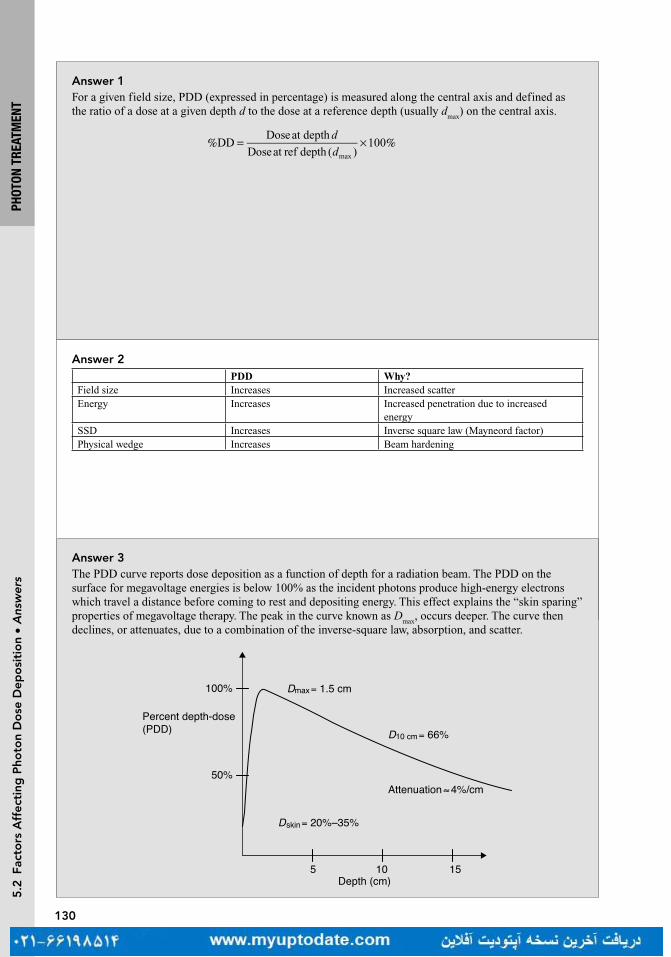
130
PHOT
ON T
REAT
MEN
T
Answer 2PDD Why?
Field size Increases Increased scatterEnergy Increases Increased penetration due to increased
energySSD Increases Inverse square law (Mayneord factor)Physical wedge Increases Beam hardening
Answer 1For a given field size, PDD (expressed in percentage) is measured along the central axis and defined as the ratio of a dose at a given depth d to the dose at a reference depth (usually d
max) on the central axis.
DDDoseat depth
Doseat ref depth ( )100
max
d
d% = × %
Answer 3The PDD curve reports dose deposition as a function of depth for a radiation beam. The PDD on the surface for megavoltage energies is below 100% as the incident photons produce high-energy electrons which travel a distance before coming to rest and depositing energy. This effect explains the “skin sparing” properties of megavoltage therapy. The peak in the curve known as D
max, occurs deeper. The curve then
declines, or attenuates, due to a combination of the inverse-square law, absorption, and scatter.
155 10Depth (cm)
100%
50%
Dmax= 1.5 cm
D10 cm= 66%
Dskin= 20%–35%
Attenuation≈4%/cm
Percent depth-dose(PDD)
5.2
Fac
tors
Aff
ecti
ng P
hoto
n D
ose
Dep
osi
tio
n •
Ans
wer
s

131
PHOT
ON T
REAT
MEN
T5
.2 F
acto
rs A
ffec
ting
Pho
ton
Do
se D
epo
siti
on
• Q
uest
ions
Question 5What is the percent change in the percent depth dose (PDD) per centimeter for cobalt-60 (Co-60), 6 and 10 MV photons under standard conditions?
Question 4What is the typical d
max for cobalt-60 (Co-60), 6, 10, 15, and 18 MV beams using a 10 cm × 10 cm
field size?
Question 6While you are on-call over the weekend you wish to treat a 20 cm long by 8 cm wide posterior to anterior (PA) spine field. Calculate the equivalent square necessary to complete the hand calculation. Why is the equivalent square necessary?

132
PHOT
ON T
REAT
MEN
T5
.2 F
acto
rs A
ffec
ting
Pho
ton
Do
se D
epo
siti
on
• A
nsw
ers
Answer 5Co-60 attenuates at approximately 4% per cm, 6 MV beams attenuate at approximately 3.5% per cm, and 10 MV attenuates at approximately 3.3% per cm. Note that these numbers are approximation, as the values change with depth.
Answer 4The d
max is slightly different for every machine and beam; however, typical values are 0.5, 1.5, 2.5, 3.0,
and 3.2 to 3.5 cm for each energy, respectively.
Answer 6
SA
P=
4
where S is side of equivalent square, A and P are, respectively, the area and perimeter of the rectangular field.
A
P )(=× ×
× +=
4 4 20 8
2 20 8
640
56
S = 11.4 cm
The square field with 11.4 cm side is equivalent to a 20 cm × 8 cm rectangular field. Usually percent depth dose (PDD) or tissue maximum ratio (TMR) values are only tabulated for square fields. A rectangular field will have approximately the same PDD or TMR as its equivalent square field. There are also other more complex methods to approximate the PDD or TMR for irregular field shapes like Clarkson’s method.
133
PHOT
ON T
REAT
MEN
T5
.2 F
acto
rs A
ffec
ting
Pho
ton
Do
se D
epo
siti
on
• Q
uest
ions
Question 7Percent depth dose (PDD) values are generally tabulated for source to skin distance (SSD) of 100 cm. How can we estimate PDDs for SSDs other than 100 cm? What is the limitation of this technique?
Question 8Using the inverse square law, derive the Mayneord F factor.
Question 9The percent depth dose (PDD) for a 6 MV beam with a 12 cm × 12 cm field size at 11 cm depth and 100 cm source to skin distance (SSD) is 64.7%. Estimate the PDD for the same field if the SSD is increased to 115 cm.
134
PHOT
ON T
REAT
MEN
T5
.2 F
acto
rs A
ffec
ting
Pho
ton
Do
se D
epo
siti
on
• A
nsw
ers
Answer 7The Mayneord F factor is used to estimate PDDs for different SSDs. The F factor is an estimation of PDD changes based solely on the inverse-square law. It assumes that the amount of scatter is constant as SSD changes, which is not quite correct and limits the accuracy of this method. For low energies, tissue-to-air ratio (TAR) correction to Mayneord F factor method can be used if TAR tables are available.
Answer 8Understanding the derivation will help you remember the F-factor equation and how it is used. Knowing the simple inverse-square relationship is all that the F factor is based on.First, the F factor is defined simply as follows:
=FPDD
PDD2
1
Since percent depth dose (PDD) increases with increasing source to skin distance (SSD), note already that by definition the F factor is greater than 1 for increasing PDD values. Now, applying the definition of PDD:
PDD
PDD2
1
2
max
1
max
F
D
D
D
D
= =
Applying the inverse-square relationship we obtain:
SSD
SSD
SSD
SSD
2 max
2
2
1 max
1
2F
d
d
d
d
=
++
++
Finally, a little algebra gives us the format we see most commonly in books:
SSD
SSD
SSD
SSD1
2
2 max
1 max
2
Fd
d
d
d= +
+× +
+
Answer 9This question requires the use of the Mayneord F factor. This method uses the inverse-square law to estimate the change in PDD due to a change in SSD. It does not account for changes in scatter which is typically ignored due to its relatively small contribution in the change in PDD. In this equation, d is the depth in tissue, r is the field size, and f is the SSD.
( )( )=
=
++
×++
PDD , ,
PDD , ,
SSD
SSD
SSD
SSD2 2
1 1
1
2
2 max
1 max
2
Fd r f
d r f
d
d
d
d
=++
×++
100 11
115 11
115 1.5
100 1.5
2
F
= 1.011F
= × =PDD(115 cm) PDD(100 cm) 1.011 65.4%
Remember that for a larger source to skin distance (SSD), the F factor is above one and the PDD will be greater.
135
PHOT
ON T
REAT
MEN
T5
.2 F
acto
rs A
ffec
ting
Pho
ton
Do
se D
epo
siti
on
• Q
uest
ions
Question 11By convention, where is field size defined?
Question 10Approximate the dose delivered to 1.5 cm if 100 cGy is delivered to a point at 10 cm depth using a 6 MV beam with a field size of 10 cm × 10 cm.
Question 12Why are high-energy photons (>10 MV) generally not recommended in the treatment of lung cancer?
136
PHOT
ON T
REAT
MEN
T5
.2 F
acto
rs A
ffec
ting
Pho
ton
Do
se D
epo
siti
on
• A
nsw
ers
Answer 10Knowing that for a 6 MV beam and a 10 cm × 10 cm field size, d
max is approximately 1.5 cm and 67% of
the Dmax
is delivered to 10 cm. Therefore, D(10 cm) = PDD(10 cm) × Dmax
and D(dmax
) = 149 cGy.
Answer 11Field size is typically defined at machine isocenter, 100 cm from the source. This would then be on the patient surface for source to skin distance setup, or at isocenter for source to axis distance (SAD) setup.
Answer 12The difference in electron density between lung and the soft tissue/bone of the chest wall presents special problems in the management of lung cancer. High-energy photons can contribute to increased scatter dosing in the lung. Also, the larger buildup region of high-energy photons may compromise tumor coverage at its periphery.

137
PHOT
ON T
REAT
MEN
T5
.2 F
acto
rs A
ffec
ting
Pho
ton
Do
se D
epo
siti
on
• Q
uest
ions
Question 13What is the “buildup region” and why does it occur? How does the buildup region depend on the energy of a photon?
Question 14How does depth of maximum dose (d
max) vary as a function of field size? Why?
Question 15Why does percent depth dose (PDD) increase with field size?
138
PHOT
ON T
REAT
MEN
T5
.2 F
acto
rs A
ffec
ting
Pho
ton
Do
se D
epo
siti
on
• A
nsw
ers
Answer 13The buildup region is the initial region on the percent depth dose (PDD) curve between the surface of the patient and d
max. Remember that dose deposition of photons is dependent on secondary electrons. While
the photons are steadily attenuated exponentially as a function of the inverse-square law, high-energy photons require some depth in tissue to generate secondary electrons, thus explaining why the deposited dose is low at the surface of the irradiated tissue.
Answer 14The depth of d
max slightly decreases as a function of field size. For example, a d
max of 1.5 cm is estimated
for a 6 MV photon and a 10 cm × 10 cm field, whereas a 20 cm × 20 cm field would expect to show a dmax
of 1.4 cm. This is due to increased scatter contributing to superficial dose deposition, bringing d
max closer
to the surface.
Answer 15PDD increases as field size increases due to scatter from the off-axis tissue. Note that both primary dose (photons emitted directly from the linac head) and secondary dose (scatter from surrounding tissue) contribute to PDD. Although both the dose at depth (D
d) and the dose at d
max rise, the D
d rises more than
the dose at dmax
(Dmax
), therefore PDD increases.

139
5.2
Fac
tors
Aff
ecti
ng P
hoto
n D
ose
Dep
osi
tio
n •
Que
stio
ns
Question 16How does the percent depth dose (PDD) field size dependence change with energy?
Question 17Explain the difference between and advantages of monitor unit (MU) calculation using tissue maximum ratio (TMR; source to axis distance [SAD] technique) compared to a percent depth dose (PDD; source to skin distance [SSD] technique).
Question 18Draw a diagram defining the tissue-to-air ratio (TAR). Explain the effect field size and beam energy has on the TAR?
PHOT
ON T
REAT
MEN
T
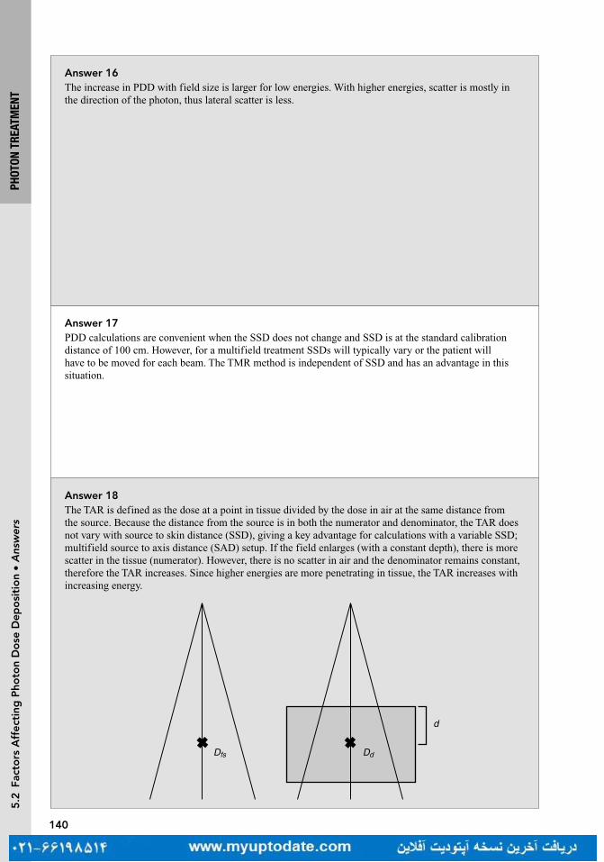
140
PHOT
ON T
REAT
MEN
T5
.2 F
acto
rs A
ffec
ting
Pho
ton
Do
se D
epo
siti
on
• A
nsw
ers
Answer 16The increase in PDD with field size is larger for low energies. With higher energies, scatter is mostly in the direction of the photon, thus lateral scatter is less.
Answer 17PDD calculations are convenient when the SSD does not change and SSD is at the standard calibration distance of 100 cm. However, for a multifield treatment SSDs will typically vary or the patient will have to be moved for each beam. The TMR method is independent of SSD and has an advantage in this situation.
Answer 18The TAR is defined as the dose at a point in tissue divided by the dose in air at the same distance from the source. Because the distance from the source is in both the numerator and denominator, the TAR does not vary with source to skin distance (SSD), giving a key advantage for calculations with a variable SSD; multifield source to axis distance (SAD) setup. If the field enlarges (with a constant depth), there is more scatter in the tissue (numerator). However, there is no scatter in air and the denominator remains constant, therefore the TAR increases. Since higher energies are more penetrating in tissue, the TAR increases with increasing energy.
d
Dfs Dd

141
PHOT
ON T
REAT
MEN
T5
.2 F
acto
rs A
ffec
ting
Pho
ton
Do
se D
epo
siti
on
• Q
uest
ions
Question 19Define and show the relationship between percent depth dose (PDD), tissue-to-air ratio (TAR), inverse-square law (ISL), and peak scatter factor (PSF) on a diagram?
Question 20What is the relationship between the peak scatter factor (PSF) and the backscatter factor (BSF)?
Question 21What is the approximate peak scatter factor (PSF) for high-energy (≥6 MV) photon beams?
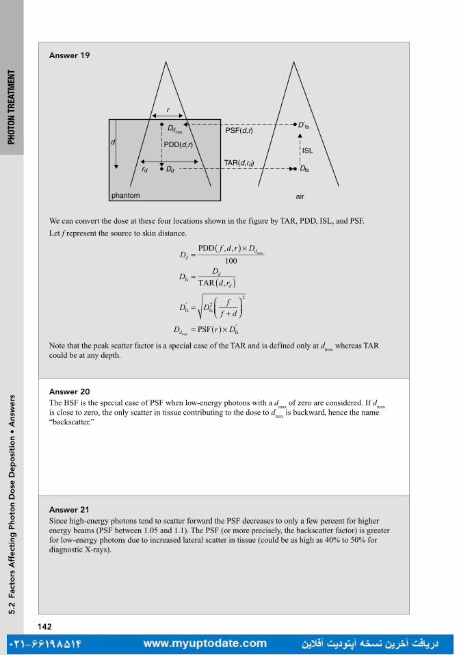
142
PHOT
ON T
REAT
MEN
T5
.2 F
acto
rs A
ffec
ting
Pho
ton
Do
se D
epo
siti
on
• A
nsw
ers
Answer 19
ISL
r
d
phantom air
Dd
PDD(d,r)
Dfs
D´fs
rd
Ddmax PSF(d,r)
TAR(d,rd)
We can convert the dose at these four locations shown in the figure by TAR, PDD, ISL, and PSF.
Let f represent the source to skin distance.
Df d r D
ddPDD , ,
100max
)(=
×
DD
d rd
d )(=TAR ,fs
D Df
f d=
+
′fs fs
2
2
D r Dd PSF fsmax)(= × ′
Note that the peak scatter factor is a special case of the TAR and is defined only at dmax
whereas TAR could be at any depth.
Answer 20The BSF is the special case of PSF when low-energy photons with a d
max of zero are considered. If d
max
is close to zero, the only scatter in tissue contributing to the dose to dmax
is backward, hence the name “backscatter.”
Answer 21Since high-energy photons tend to scatter forward the PSF decreases to only a few percent for higher energy beams (PSF between 1.05 and 1.1). The PSF (or more precisely, the backscatter factor) is greater for low-energy photons due to increased lateral scatter in tissue (could be as high as 40% to 50% for diagnostic X-rays).
143
PHOT
ON T
REAT
MEN
T5
.2 F
acto
rs A
ffec
ting
Pho
ton
Do
se D
epo
siti
on
• Q
uest
ions
Question 23Both the definition of percent depth dose (PDD) and tissue maximum ratio (TMR) could be written as
/max
D Dd d . Why are they different?
Question 22Define tissue maximum ratio (TMR). How does it relate to tissue-to-air ratio (TAR)?
Question 24You plan to treat a 10 cm × 10 cm tumor in a large patient with a single 6 MV field. Rather than the classic source to skin distance (SSD) setup, you choose a source to axis distance (SAD) setup and place the isocenter in the target a depth of 10 cm from the surface and prescribe 10 Gy in a single fraction. The patient is delayed after simulation and returns three weeks later, having lost 40 lbs. From a new CT you measure the new depth to be 8 cm. Explain two methods of calculating the new dose to the isocenter given the same SAD.
144
PHOT
ON T
REAT
MEN
T5
.2 F
acto
rs A
ffec
ting
Pho
ton
Do
se D
epo
siti
on
• A
nsw
ers
Answer 23PDD is calculated using the same source to skin distance (SSD) and different depths, TMR is calculated using the same source to axis distance (SAD) and therefore is independent of SSD.
Answer 22
TMRDose at depth
Dose at max
d
d=
Note that both doses are calculated using the same source to point distance (ie, source to axis distance [SAD]). TMR is related to TAR by the peak scatter factor (PSF) (derivation not shown):
=TMRTAR
PSF
Answer 24This is an example that takes advantage of tissue maximum ratio (TMR) calculations. Since the source to skin distance (SSD) has now changed, using a percent depth dose (PDD) approach would require a Mayneord calculation. The TMR approach is independent of the SSD and requires only the depth in tissue to calculate, assuming the field size (defined at depth) has not changed. TMR can be found in a table. Using the appropriate values as follows, the new dose to the isocenter is 10.75 Gy:
D
D
D
Dd
d
))
))
((
((
))
((
= = = =SAD,Field Size
SAD,Field Size
100 cm, 10 cm
100 cm, 10 cm
TMR 8 cm
TMR 10 cm
0.841
0.7821.0751
2
8 cm
10 cm

145
PHOT
ON T
REAT
MEN
T5
.2 F
acto
rs A
ffec
ting
Pho
ton
Do
se D
epo
siti
on
• Q
uest
ions
Question 25The tissue maximum ratios (TMR) of a 5 cm × 5 cm field size 16 MV beam source at 8 and 10 cm depth are 0.80 and 0.75, respectively. An oddly shaped square patient made of water has an anterior to posterior/posterior to anterior (AP/PA) diameter of 16 cm and a lateral diameter of 20 cm at the isocenter placed in the center of the patient. What is the maximum dose outside the target area if a four-field box approach is used to treat a single fraction of 2 Gy to the isocenter and with equal weights from each beam of 5 cm × 5 cm size?
Question 26A patient’s surface can be irregular depending on the site that we are treating. However, it is often desirable to have a uniform dose distribution. How are the surface irregularities managed during radiation therapy? Discuss advantages and disadvantages of all methods.

146
5.2
Fac
tors
Aff
ecti
ng P
hoto
n D
ose
Dep
osi
tio
n •
Ans
wer
s
Answer 25This question illustrates the value of the TMR. For a single isocenter setup, the contribution from each beam will be even at 0.5 Gy. The actual d
max is not necessary information and will be the location of the
hot spot. Realizing that the largest hot spot for one field would be at the deepest prescription depth, we can calculate this using the TMR definition.
TMRSAD, Field Size
SAD, Field Sizedepth
max
D
Dd
( )( )=
0.75100 cm, 5 cm
100 cm, 5 cm
0.5 Gy10 cm
max max
D
D Dd d
( )( )= =
=Dd 0.667 Gymax
(33% hot spot)
L = 20 cm
W = 16 cm
Answer 26A bolus material can be placed on the skin surface to even out the irregularity of the patient surface. Adding a bolus will, however, remove the skin sparing effect of megavoltage radiation. Alternatively, compensators may be used. A compensator filter attenuates the beam in the region of the “missing tissue.” Other techniques to manage surface irregularities include using wedge filters or blocking parts of the tissue for some of the fractions of the treatment.
PHOT
ON T
REAT
MEN
T
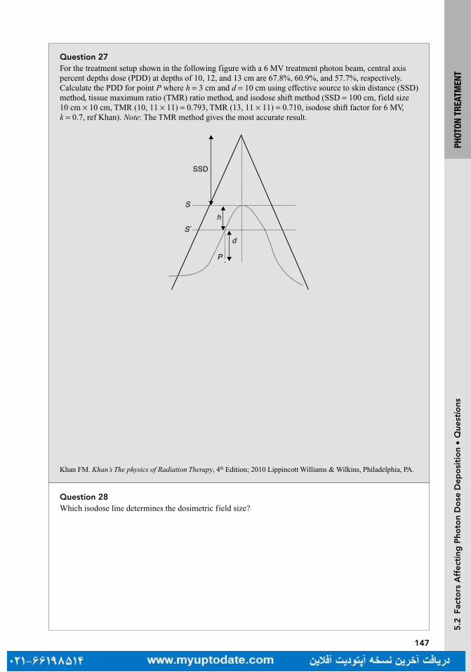
147
PHOT
ON T
REAT
MEN
T5
.2 F
acto
rs A
ffec
ting
Pho
ton
Do
se D
epo
siti
on
• Q
uest
ions
Question 27For the treatment setup shown in the following figure with a 6 MV treatment photon beam, central axis percent depths dose (PDD) at depths of 10, 12, and 13 cm are 67.8%, 60.9%, and 57.7%, respectively. Calculate the PDD for point P where h = 3 cm and d = 10 cm using effective source to skin distance (SSD) method, tissue maximum ratio (TMR) ratio method, and isodose shift method (SSD = 100 cm, field size 10 cm × 10 cm, TMR (10, 11 × 11) = 0.793, TMR (13, 11 × 11) = 0.710, isodose shift factor for 6 MV, k = 0.7, ref Khan). Note: The TMR method gives the most accurate result.
SSD
S
S´h
P
d
Question 28Which isodose line determines the dosimetric field size?
Khan FM. Khan’s The physics of Radiation Therapy, 4th Edition; 2010 Lippincott Williams & Wilkins, Philadelphia, PA.

148
PHOT
ON T
REAT
MEN
T
Answer 27Effective SSD method: This method is correcting the d
max value difference between S and S′ planes using
the inverse-square law factor:
=+
+ +
=+
+ +
=Correction Factor, CF
SSD
SSD
100 1.5
100 3 1.50.94max
max
2 2d
h d
P = × =PDD 0.94 67.8 63.7%
TMR method: In this case, the CF will be the ratio of the TMR values using S and S′ as flat patient surface.
Field size projected at point P is 11 cm × 11 cm:
CFTMR 10, 11 11
TMR(13, 11 11)
0.793
0.7101.12
( )= ××
= =
P = × =PDD 57.7 1.12 64.4%
Isodose shift method: We need to find the value of PDD for the same isodose lines passing through depth x on central axis and P as illustrated in the following:
x P=PDD PDD such that 10, then 12x k h x+ × = = where k = 0.7.
PDD PDD 12 cm, 10 10 60.9%P ( )= × =
S
S´
P
x
Answer 28The 50% isodose line defines the field size. The field’s size changes with distance due to divergence, and so is defined at the machine isocenter.
5.2
Fac
tors
Aff
ecti
ng P
hoto
n D
ose
Dep
osi
tio
n •
Ans
wer
s

149
PHOT
ON T
REAT
MEN
T5
.3 M
oni
tor
Uni
t C
alcu
lati
ons
• Q
uest
ions
Question 2What two components make up the total dose to tissue at depth?
Question 1 5.3 MONITOR UNIT CALCULATIONSWhat are “reference conditions” and why are they important? Give an example of common “reference conditions.”
Question 29What is the name of the technique used to calculate dose from irregular fields?
Question 3Suppose a 6 MV beam is unconventionally calibrated to deliver 1.5 cGy/MU to d
max (1.5 cm) at a source to
skin distance (SSD) of 100 cm via a 10 cm × 10 cm field in water. How many monitor units (MUs) would be necessary to deliver 100 cGy to 10 cm via a 10 cm × 10 cm field in water (SSD = 100 cm)?

150
PHOT
ON T
REAT
MEN
T
Almond PR, Biggs PJ, Coursey BM, et al. AAPM’s TG-51 protocol for clinical reference dosimetry of high-energy photon and electron beams. Med Phys. 1999;26(9):1847–1870.
Answer 2The dose to a point at depth is the sum of the primary dose (dose directly from the head of the machine) and the scattered dose. The scattered dose may come from scatter within the machine or from within the patient.
Answer 1Reference conditions are the conditions at which the beam is calibrated. It is critically important to specify these conditions, otherwise systematic errors in dose calculations can occur. One example of common reference conditions is that the beam may be calibrated (per AAPM TG-51) such that 1 monitor unit (MU) is equal to 1 cGy deposited by a 6 MV photon at d
max using a 10 cm × 10 cm field size in water with a
source to skin distance (SSD) of 100 cm. Note that field size is determined at 100 cm from the source.
Answer 29Clarkson’s method. The technique involves dividing an irregular field with blocking into sectors to approximate the scatter from each sector.
Answer 3This is the simplest form of MU calculation:
dDose
MUat depth
Dose
MUat PDDmax=
×
Knowing that the percent depth dose (PDD) at 10 cm of a 6 MV beam is roughly 67%:
Dose
MUat depth 1.5
cGy
MU0.67 1.005 cGy/MU( )=
× =
MU Required100 cGy
1.005 cGy/MU99.5 100 MU= = ≈
5.3
Mo
nito
r U
nit
Cal
cula
tio
ns •
Ans
wer
s

151
PHOT
ON T
REAT
MEN
T5
.3 M
oni
tor
Uni
t C
alcu
lati
ons
• Q
uest
ions
Question 4Now suppose a 6 MV beam is even more unconventionally calibrated to deliver 1.5 cGy/MU at 3 cm with a source to skin distance of 100 cm via a 10 cm × 10 cm field in water. Given that the percent depth dose (PDD) at 3 cm of a 6 MV beam is roughly 95%, how many monitor units (MUs) would be necessary to deliver 100 cGy to 10 cm via a 10 cm × 10 cm field in water?
Question 6Explain the terms S
c and S
p. What are they a function of ? What are their typical values?
Question 5Consider a 6 MV beam with a source to skin distance (SSD) of 100 cm and a field size of 10 cm × 10 cm. The physician wishes to prescribe 180 cGy to a depth of 7.0 cm. You know that the dose rate is 0.956 cGy/ MU at d
max and the percent depth dose at 7.0 cm is 78.2%. How many monitor units (MUs)
should be given?
152
PHOT
ON T
REAT
MEN
T5
.3 M
oni
tor
Uni
t C
alcu
lati
ons
• A
nsw
ers
Answer 4This is one step more complicated than the previous question (Question 3). Since the dose rate is calibrated at a depth other than d
max, we need to correct via the inverse-square law. This is because the
definition of PDD is percent of Dmax
(dmax
= 1.5 cm).
=
×
Dose
MUat depth
Dose
MUat PDDmaxd
but
=
/d
Dose
MUat
Dose
MUat depth 3cm PDD (3cm)max
=
/d
Dose
MUat 1.5
cGy
MU0.95max
=Dose
MUat 1.58
cGy
MUmaxd
Now, we can use the previous equation along with the PDD given.
=
×
Dose
MUat depth 1.58
cGy
MU0.67
=Dose
MUat depth 1.06
cGy
MU
So to deliver 100 cGy, we need 106 MU.
Answer 6S
c is a measure of the collimator scatter and S
p is a measure of the phantom (tissue) scatter. Remember that
photons interacting in the head of the machine tend to scatter (from the target, flattening filter, jaws, etc.) and enter the patient at various angles (S
c). Once the photons enter the patient, they are scattered again
(Sp). S
c and S
p are therefore functions of the field size primarily since more scatter occurs at larger field
apertures. Since they are correction factors they are typically close to 1 but may range from 0.9 for small fields to 1.1 for large fields. Sometimes for simplicity they are combined into a single term, S
c,p which is
simply Sc × S
p. Note that the field size for S
c is defined at the isocenter. However, the field size for S
p is
defined at depth, since the internal scatter can change as the beam diverges with depth.
Answer 5
=
×
Dose
MUat depth
Dose
MUat reference PDD
=
×
Dose
MUat depth 0.956
cGy
MU(0.782)
=Dose
MUat depth 0.748
cGy
MU
So to give 180 cGy with a dose rate of 0.748 cGy/MU:
= ≈MU180 cGy
0.748cGy
MU
241 MU
Gibbons J, Antolak JA, Followill DS, et al. Monitor unit calculations for external photon and electron beams: Report of the AAPM Therapy Physics Committee Task Group No. 71. Med Phys. 2014;41(3):031501.

153
PHOT
ON T
REAT
MEN
T5
.3 M
oni
tor
Uni
t C
alcu
lati
ons
• Q
uest
ions
Question 7How is the collimator scatter factor S
c measured?
Question 10Now the 6 MV beam is calibrated as per the usual convention [1 cGy/MU (monitor unit) at d
max with a
field size of 10 cm × 10 cm at the surface at a source to skin distance (SSD) of 100 cm]. Calculate the cGy/MU delivered at 10 cm via a 5 cm × 5 cm field with an extended SSD of 110 cm. Assume the percent depth dose (10 cm) continues to be 66%, S
c is 0.951 and S
p is 0.954.
Question 9Now suppose that a 6 MV beam is again unconventionally calibrated to deliver 1.5 cGy/MU to d
max
(1.5 cm) at a source to skin distance of 100 cm via a 10 cm × 10 cm field in water. The percent depth dose (PDD) at 10 cm for a 6 MV beam is roughly 66%. How many monitor units (MUs) would be necessary to deliver 100 cGy to 10 cm via a 5 cm × 5 cm field in water? Assume S
c = 0.967 and S
p = 0.974.
Question 8How is the phantom scatter factor S
p measured?
154
PHOT
ON T
REAT
MEN
T5
.3 M
oni
tor
Uni
t C
alcu
lati
ons
• A
nsw
ers
Answer 7S
c is the ratio of output for a given field size to a reference field size (10 cm × 10 cm) in air measured at
isocenter (100 cm). It can be measured with an ion chamber with a build-up cap.
Answer 8S
p is the ratio of dose for a given field size to a reference field size (10 cm × 10 cm) in a phantom at d
max
with identical collimator opening. Theoretically it could be measured using phantoms of various sizes with a larger collimator opening. But in practice it is measured indirectly using the following equation:
= /S S Sp c p c,
where Sc, p
is the total scatter factor and defined as the ratio of dose for a given field size to reference field size (10 cm × 10 cm) in phantom at depth of maximum dose (d
max). S
c,p is defined at d
max but actual
measurements are done at larger depths (ie, 10 cm) to avoid electron contamination and converted to dmax
using tabulated PDD values.
Answer 9This is the same as question 3 but with a smaller field size. In Question 3, S
c and S
p were essentially
counted as 1 because the field size was constant between the calibration conditions and the conditions we were interested in. Now that the field size changed, we need to introduce S
c and S
p in the equation:
D
D S Sc p
=× × ×′MU
PDD0
=
× × ×
= ≈MU100 cGy
1.5cGy
MU0.967 0.974 0.66
107.3 107
Note that the number of MUs required is slightly higher than before due to a smaller field size. This is due to “increased scatter” as represented by S
c and S
p.
Answer 10This question requires both an inverse-square correction and a correction for S
c,p:
Dose
MUat depth
Dose
MUat reference PDD
SSD
SSD0 max
max
2
S Sd
dc p=
× × × × +
+
Dose
MUat depth 1
cGy
MU0.66 0.951 0.954
100 1.5 cm
110 1.5 cm
2
=
× × × × +
+
Dose
MUat depth 0.496
cGy
MU=

155
PHOT
ON T
REAT
MEN
T5
.3 M
oni
tor
Uni
t C
alcu
lati
ons
• Q
uest
ions
Question 11In the AAPM TG-71 report, what is the equation used to perform a monitor unit (MU) calculation using source to skin distance (SSD) technique?
Question 12A patient is treated with 6 MV photons to 100 cGy via a 10 cm × 10 cm field to 8 cm depth at 100 cm source to skin distance (SSD). The percent depth dose (PDD) at this point is 74.3%.
How many monitor units (MU) are required? Assume the calibration conditions of 1 cGy/MU to d
max (1.5 cm) with a 10 cm × 10 cm field size.
Question 13The source to skin distance (SSD) changes to 115 cm. How many monitor units (MUs) are now required? Use the percent depth dose (PDD) method. Field size is kept at 10 cm × 10 cm at SSD. S
c (8.7 cm) = 0.995.

156
PHOT
ON T
REAT
MEN
T5
.3 M
oni
tor
Uni
t C
alcu
lati
ons
• A
nsw
ers
Answer 11So far we have answered these questions using “dose rate” notation but this is not the same format used by the official reports. With a bit of algebra you will see that the two methods are equivalent. The following equation is a simple form of the MU calculation formula and a great starting place for understanding MU calculations. Note that this simplified equation does not account for off-axis point calculations, wedges, or blocks which will be covered in the next questions:
MU
( ) ( ) PDD ( , ,SSD)SSD
SSD00 0
0
2
0
D
D S r S r d rd
dc c p d N
=
× × × × ++
′
D: The dose at the point of interest.
D0′: Dose per MU under calibration conditions.
d: Depth of the point of calculation.
d0: The normalization depth for photon and electron dosimetry, typically d
max.
rc: The side of the equivalent square for the collimator field size defined at isocenter.
rd: The side of the equivalent square for the field size incident on the patient, defined at the surface and at
depth d, respectively.
Sc: Collimator scatter factor.
Sp: Phantom scatter factor.
Answer 12Remember that at calibration conditions (10 cm × 10 cm, SSD = 100 cm), S
c,p = 1. Therefore,
=
⋅ × × × ++
′
D
D S r S r d rd
dc c p d N
MU
( ) ( ) PDD ( , , SSD)SSD
SSD00 0
0
2
0
=× × +
+
= ≈MU100 cGy
1cGy
MU0.743
100 cm 1.5 cm
100 cm 1.5 cm
134.6 MU 135 MU2
Answer 13Since the SSD has now changed, we must first convert the PDD using the Mayneord factor:
=++
×++
SSD
SSD
SSD
SSD1
2
2 max
1 max
2
Fd
d
D
D
=++
×++
=
100 cm 8 cm
115 cm 8 cm
115 cm 1.5 cm
100 cm 1.5 cm1.0157
2
F
So PDD2 = 0.743 × 1.0157 = 0.755
= ≈100
11510 8.7 cmrc
=
⋅ × × × ++
′
D
D S r S r d rd
dc c p d
MU
( ) ( ) PDD ( , , SSD)SSD
SSD0 20 0
0
2
0
=× × +
+
=MU100 cGy
1cGy
MU0.995 0.755
100 cm 1.5 cm
115 cm 1.5 cm
175.4 MU2
Gibbons J, Antolak JA, Followill DS, et al. Monitor unit calculations for external photon and electron beams: Report of the AAPM Therapy Physics Committee Task Group No. 71. Med Phys. 2014;41(3):031501.
157
PHOT
ON T
REAT
MEN
T5
.3 M
oni
tor
Uni
t C
alcu
lati
ons
• Q
uest
ions
Question 14Solve the previous question (Question 13) using the tissue maximum ratio (TMR) method. TMR (d = 8 cm, r = 10 cm) = 0.830, TMR (d = 8 cm, r = 11 cm) = 0.837 S
p (11 cm) = 1.003
= ==123
11510 10.7 cm8 cmrd
Question 15Write the equation TG-71 uses for monitor unit (MU) calculation of beams designed with source to axis distance (SAD) technique. This time, account for blocks, wedges, and off-axis calculations.
Question 16124 monitor units (MUs) are required to deliver a single 1 Gy fraction to a target. 50% of the field size is then blocked to save normal tissue. S
c,p drops from 1 to 0.889 and the tissue maximum ratio (TMR)
decreases from 0.782 to 0.747. How many MUs are now necessary to deliver the same dose to the target?
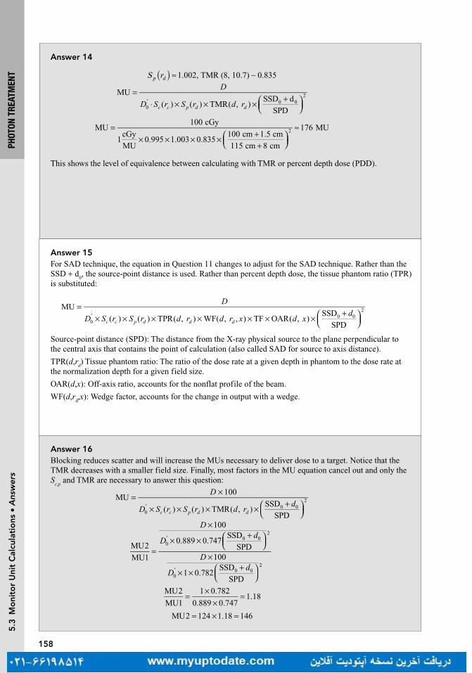
158
PHOT
ON T
REAT
MEN
T5
.3 M
oni
tor
Uni
t C
alcu
lati
ons
• A
nsw
ers
Answer 14
S 1.002, TMR (8, 10.7) 0.835p dr )( ≈ ∼
=⋅ × × × +
′
D
D S r S r d rc c p d d
MU
( ) ( ) TMR( , )SSD d
SPD00 0
2
=× × × × +
+
≈MU100 cGy
1cGy
MU0.995 1.003 0.835
100 cm 1.5 cm
115 cm 8 cm
176 MU2
This shows the level of equivalence between calculating with TMR or percent depth dose (PDD).
Answer 16Blocking reduces scatter and will increase the MUs necessary to deliver dose to a target. Notice that the TMR decreases with a smaller field size. Finally, most factors in the MU equation cancel out and only the S
c,p and TMR are necessary to answer this question:
MU100
( ) ( ) TMR( , )SSD
SPD00 0
2
D
D S r S r d rd
c c p d d
= ×
× × × × +
′
=
×
× × +
×
× × +
′
′
D
Dd
D
Dd
MU2
MU1
100
0.889 0.747SSD
SPD100
1 0.782SSD
SPD
00 0
2
00 0
2
=×
×=
MU2
MU1
1 0.782
0.889 0.7471.18
= × =MU2 124 1.18 146
Answer 15For SAD technique, the equation in Question 11 changes to adjust for the SAD technique. Rather than the SSD + d
0, the source-point distance is used. Rather than percent depth dose, the tissue phantom ratio (TPR)
is substituted:
=× × × × × × × +
′
D
D S r S r d r d r x d xd
c c p d d d
MU
( ) ( ) TPR( , ) WF( , , ) TF OAR( , )SSD
SPD00 0
2
Source-point distance (SPD): The distance from the X-ray physical source to the plane perpendicular to the central axis that contains the point of calculation (also called SAD for source to axis distance).
TPR(d,rd) Tissue phantom ratio: The ratio of the dose rate at a given depth in phantom to the dose rate at
the normalization depth for a given field size.
OAR(d,x): Off-axis ratio, accounts for the nonflat profile of the beam.
WF(d,rd,x): Wedge factor, accounts for the change in output with a wedge.
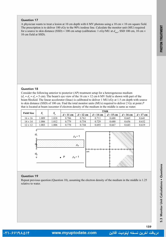
159
PHOT
ON T
REAT
MEN
T5
.3 M
oni
tor
Uni
t C
alcu
lati
ons
• Q
uest
ions
Question 17A physician wants to treat a lesion at 10 cm depth with 6 MV photons using a 10 cm × 10 cm square field. The prescription is to deliver 180 cGy to the 90% isodose line. Calculate the monitor unit (MU) required for a source to skin distance (SSD) = 100 cm setup (calibration: 1 cGy/MU at d
max, SSD 100 cm, 10 cm ×
10 cm field at SSD).
Question 18Consider the following anterior to posterior (AP) treatment setup for a heterogeneous medium (d
1 = d
2 = d
3 = 5 cm). The beam’s eye view of the 16 cm × 12 cm 6 MV field is shown with part of the
beam blocked. The linear accelerator (linac) is calibrated to deliver 1 MU/cGy at 1.5 cm depth with source to skin distance (SSD) of 100 cm. Find the total monitor units (MUs) required to deliver 2 Gy at point P that is located at beam isocenter if electron density of the medium in the middle is same as water.
Field Size Sc
Sp
TMRd = 11 cm d = 12 cm d = 14 cm d = 15 cm d = 16 cm d = 17 cm
16 × 16 1.009 1.018 0.786 0.761 0.711 0.688 0.665 0.64114 × 14 1.006 1.012 0.779 0.754 0.729 0.680 0.656 0.63212 × 12 1.003 1.006 0.770 0.744 0.693 0.667 0.643 0.619
cm
P
ρed2
d1
d3
ρe�= 1
ρe = 1
Question 19Repeat previous question (Question 18), assuming the electron density of the medium in the middle is 1.25 relative to water.

160
PHOT
ON T
REAT
MEN
T5
.3 M
oni
tor
Uni
t C
alcu
lati
ons
• A
nsw
ers
Answer 17Percent depth dose (PDD) for 6 MV photons at 10 cm depth is 67%. We want to deliver 180/0.90 = 200 cGy to central axis. From the definition of PDD,
=×
20067
100maxD
= 298.5 cGymaxD
Since the linac is calibrated to deliver 1 cGy/MU at dmax
for 10 cm × 10 cm field at SSD of 100 cm, we need 298.5 MU.
Answer 18
=× × × × +
′
D
D S r S r d rd
c c p d d
MU
( ) ( ) TMR( , )SSD
SPD00 0
2
+
=
SSD
SPD1.030 0
2d
From the beam’s eye view, 25% of the field is blocked. So total area unblocked is 16 × 12 × 0.75 = 144 cm2.
Equivalent square (rd) for the blocked field is roughly =144 cm 12 cm2 .
Equivalent square (rc) for S
c is
( )× ×
× +≈
4 16 cm 12 cm
2 12 cm 16 cm14 cm
=× × × ×
≈MU200 cGy
1 1.006 1.006 0.667 1.03288
Answer 19Equivalent depth,
Use interpolation for TMR (16.25 cm,12 × 12) = 0.619 + 0.25(0.643 − 0.619) = 0.625:
Correction Factor, =×
×= =CF
TMR(16.25 cm, 12 12 cm)
TMR(15 cm, 12 12 cm)
0.625
0.6670.94
=× × × × ×
≈MU200 cGy
1 1.006 1.006 0.667 1.03 0.94306
D
D S r S r d r dc c p d d
=× × × × + ×
MU( ) ( ) TMR( , ) ((SSD ) / SPD) CF0
'0 0
2
5 1.25 5 5 16.25 cmeq 1 2 3d d d deρ= + + = + × + =

161
PHOT
ON T
REAT
MEN
T5
.3 M
oni
tor
Uni
t C
alcu
lati
ons
• Q
uest
ions
Question 22Which has a larger geometric penumbra—a cobalt-60 (Co-60) machine or a modern linear accelerator?
Question 21By approximately how much does the dose rate of cobalt-60 (Co-60) decrease in one month?
Question 20Repeat Question 18, assuming the electron density of the medium in the middle is 0.25 relative to water.
Question 23To calibrate a linear accelerator we use an ion chamber to relate the output of the machine as measured by monitor units to the dose delivered under certain conditions. Explain how a cobalt-60 machine is calibrated.

162
PHOT
ON T
REAT
MEN
T5
.3 M
oni
tor
Uni
t C
alcu
lati
ons
• A
nsw
ers
Answer 20Equivalent depth, ρ= + + = + × + =5 0.25 5 5 11.25 cmeq 1 2 3d d d de
Interpolation of TMR (11.25 cm, 12 × 12) = 0.744 + 0.25(0.770 − 0.744) = 0.751
Correction Factor, =×
×= =CF
TMR(11.25 cm, 12 12 cm)
TMR(15 cm, 12 12 cm)
0.751
0.6671.13
MU200 cGy
1 1.006 1.006 0.667 1.03 1.13255=
× × × × ×≈
Answer 21A “rule of thumb” is that cobalt decays by approximately 1% per month. While this is a good answer to remember for estimation, it will not work over a long period of time. The precise answer, using the 5.26 year half-life is − × ×e 0.693 1 month/(12 months/year 5.26 years) = 1.09%.
Answer 22Typically Co-60 machines have a larger geometric penumbra because the cobalt source usually is a cylinder roughly 1 to 2 cm in diameter as opposed to the roughly 3 mm diameter pencil beam of electrons that interacts with a Tungsten target in the linear accelerator (linac) head.
Answer 23Cobalt-60 machines are controlled using a timer. Because the source is always “on,” it is held inside the shielded head of the machine. When the patient is in position, the shield is removed. Calibration, therefore, is performed by measuring the time it takes for the source to deposit dose, which is a function of the activity of the source. A fresh source typically has a dose rate of 240 cGy/min at a source to axis distance (SAD) of 80 cm.

163
PHOT
ON T
REAT
MEN
T5
.3 M
oni
tor
Uni
t C
alcu
lati
ons
• Q
uest
ions
Question 24A single-fraction dose requires 5 min to deliver on a cobalt-60 machine without accounting for a 26-s time correction. What is the total time required to deliver the fraction?
Question 25A dose of 250 cGy is prescribed to a depth of 5 cm. The patient is treated at 100 cm source to skin distance using a 6 MV with a field size of 16 cm × 12 cm. How many monitor units (MUs) should be delivered?
Sc, p
= 1.023, PDD (5, 13.7, 100) = 0.877
Question 26A 36 cm long field is necessary to treat the entire spinal column of a patient. The spinal column is at an average depth of 5.0 cm. The patient is treated at an extended source to skin distance of 115 cm of 6 MV. The collimator jaw is set to 30 cm × 4 cm. Use the tissue maximum ratio (TMR) method to calculate the required monitor unit (MU) if the prescription dose is 300 cGy. Use S
c (7.1) = 0.987, S
p (8.5) = 0.996 and
TMR (5, 8.5) = 0.921.
Question 27A 36 cm long field is necessary to treat the entire spinal column of a patient. The spinal column is at an average of 5.0 cm depth. The patient is treated at an extended source to skin distance (SSD) of 115 cm of 6 MV. The collimator jaw is set to 30 cm × 4 cm. Use the percent depth dose (PDD) method to calculate the required monitor unit (MU) if the prescription dose is 300 cGy. Use PDD (5, 7.096, 100) = 0.858, S
c (7.1) = 0.987 and S
p (8.1) = 0.995.

164
PHOT
ON T
REAT
MEN
T5
.3 M
oni
tor
Uni
t C
alcu
lati
ons
• A
nsw
ers
Answer 24The time correction accounts for the time it takes to move the shielding away from the cobalt source. For a fraction of this time, the source is not entirely exposed and is not delivering the full dose rate. Therefore, the time error is added onto the time it takes to deliver the source. The final time it takes to deliver this fraction is simply 5 min and 26 s.
Answer 25Equivalent square: 4 (anterior/posterior [A/P]) = 4 × 3.4 = 13.7 cm
Look up data tables from a specific machine to find:
MU = 250/(0.877 × 1.023) = 278.7 = 279
Sc, p
= 1.023, PDD (5, 13.7, 100) = 0.877
Answer 26Equivalent square: 4 (anterior/posterior [A/P]) = 7.06 cm
Projected equivalent square size at the treatment depth = 8.5 cm
TMR (5, 8.5) = 0.921
Sc (7.1) S
p (8.5) = 0.987 × 0.996 = 0.983
SAD factor = (101.5/(SSD + d))2 = 0.715
MU = 300/(0.983 × 0.921 × 0.715) = 464
Answer 27Equivalent field size: 4 (anterior/posterior [A/P]) = 7.06
Projected equivalent field size at 115 cm SSD = 8.1 cm
PDD (5, 7.06, 100) = 0.858
F factor = ((115 + 1.5)/(115 + 5))2/((100 + 5)/(100 + 1.5))2 = 0.942 × 1.07 = 1.008
PDD (5, 8.1, 115) = 0.864
Sc (7.1) S
p (8.1) = 0.987 × 0.995 = 0.982
SSD factor = (101.5/(115 + 1.5))2 = 0.759
MU = 300/(0.982 × 0.864 × 0.759) = 464

167
BASI
C TR
EATM
ENT
PLAN
NING
Que
stio
ns
Question 4What is the definition of a hot spot in an external beam plan?
Question 3What is bolus?
Question 2What is the main advantage of treating patients in the prone position with a belly board for patients with rectal cancer?
Question 1Why is a 5° posteriorly titled gantry angle necessary in whole brain treatment?
Turn page to see the answers.
168
BASI
C TR
EATM
ENT
PLAN
NING
Ans
wer
s
Answer 4A hot spot is a small volume that receives the highest radiation dose, higher than the prescribed dose of the target volume. In conventional radiation therapy, prior to the use of three-dimensional (3D) images and dose calculation, a hot spot was defined as an area encompassing 2 cm2 contiguous area that receives the highest radiation dose. In 3D conformal therapy (3DCRT), a hot spot is defined as a volume (0.03 mL) receiving the highest radiation dose.
Answer 3Bolus is any material (typically water equivalent) added on or near the patient surface. The use of bolus is to increase the surface (skin) dose when the tumor volume is located superficially. Sometimes bolus is also used to compensate for missing tissue such as in the treatment of an orbit when the eye has been removed.
Answer 2A belly board has an indented space for the entire abdomen to fall into, displacing the small bowel more anteriorly and further separating it from the tumor target volume, and minimizing the radiation dose to the small bowel. Another frequently used technique that also decreases the amount of small bowel in the field is to treat the patient with a full bladder. The full bladder will push the tumor volume inferiorly and separate the small bowel away from the tumor volume.
Answer 1With a patient in supine position, a 5° posteriorly titled gantry angle resulting in 275° gantry angle from the patient’s right and 85° gantry angle from the patient’s left, will avoid the divergence of the beams into the lenses and minimize the lens dose.

169
BASI
C TR
EATM
ENT
PLAN
NING
Que
stio
ns
Question 7What happens to the size of the penumbra at a depth of 10 cm? (Assume the other parameters from Question 6 remain the same.)
Question 6What is the geometric penumbra (P) at the skin given the following data: source size = 2 cm, source to skin distance (SSD) = 100 cm, source to collimator distance (SCD) = 56 cm?
Question 5When parallel opposed fields (anterior-posterior and posterior-anterior [AP/PA]) are used to treat a tumor in the chest region and the isocenter is located at mid-depth, in which field is the length of cord treated longer?
Question 8What would be the equivalent square for an open 8 cm × 24 cm field size?

170
BASI
C TR
EATM
ENT
PLAN
NING
Ans
wer
s
Answer 7
= × + −P 2
100 10 56
56
=P 1.93 cm
Penumbra (P) width increases with an increase in depth assuming source to skin distance (SSD), source to collimator distance (SCD), and source size remain the same.
Answer 6Use the following formula:
= × + −P source size
SSD depth SCD
SCD
= × −P 2
100 56
56
=P 1.57 cm.
Answer 5The cord is located posteriorly in the patient body. Therefore, the length of cord included in the anterior field is greater than that in the posterior field due to beam divergence. The two beams treat the same area only at the depth of the isocenter.
Answer 8Use the following formula:
= × a
pEQ 4
= × ×+ + +
EQ 4(8 24)
(8 8 24 24)
EQ 12 cm=
Where a is the area and p is the perimeter. The equivalent square has the same percent depth dose (PDD) as the rectangle, and can be used for monitor unit calculation for the rectangle. The formula is based on equating the ratio of area/perimeter between the square and rectangle.
171
BASI
C TR
EATM
ENT
PLAN
NING
Que
stio
ns
Question 9A 20 cm × 20 cm field size at 100 cm source to skin distance (SSD) will be projected to what size at a depth of 15 cm from the skin?
Question 11What is the wedge transmission factor if the output without the wedge is 222 cGy/MU and the output with the wedge at the same point is 125 cGy/MU?
Question 10What is the principal advantage of isocentric techniques over source to skin distance (SSD) technique for a treatment with multiple fields?
Question 12An object that measures 4 cm is placed on the patient’s skin at 100 cm source to skin distance (SSD). Its image on the radiograph measures 5.4 cm. What is the target to film distance (TFD)?
172
BASI
C TR
EATM
ENT
PLAN
NING
Ans
wer
s
Answer 11The wedge transmission factor is 0.563 using the following formula:
125cGy/MU
222cGy/MU0.563=
The wedge transmission factor (or simply wedge factor) is defined as the ratio of output with the wedge divided by the output without the wedge. Due to the large thickness of the wedge, the wedge factor makes a substantial adjustment in monitor units.
Answer 10The isocentric technique eliminates the need to move the patient between fields. The isocenter is placed within the patient at a planned depth and the beams are directed from different directions. This technique relies primarily on the accuracy of machine isocentricity and not on the skin marks which can be unreliable points of reference.
Answer 9The field size at a depth of 15 cm will be projected to 23 cm × 23 cm using the following similar triangles formula:
Field size
Field size
SSD1
SSD2=@ SSD1
@ SSD2
X
20 100
115=
X 23.=
Answer 12The TFD is 135 cm using the following formula:
= ×TFD
TOD image size
object size
= ×TFD
100 5.4
4
where TOD is the target object distance. As the object is on the skin, the TOD equals the SSD.

173
BASI
C TR
EATM
ENT
PLAN
NING
Que
stio
ns
Question 16Calculate the angle of the lateral tangent beam for a breast treatment if the medial tangent beam is at the gantry angle of 56° and a symmetric field size of 10 cm (Width) and 18 cm (Length) at 100 cm source to axis distance (SAD) is used.
Question 15Calculate the field gap on the patient’s skin surface for the following two fields to be matched at a depth of 5 cm from the skin surface.12 cm W × 20 cm L at 100 cm source to skin distance (SSD)12 cm W × 24 cm L at 100 cm SSD
Question 14When planning for whole breast treatment using tangent fields, how is the separation defined? At what separation should one consider increasing the beam energy from 6 to 10 MV to maintain a uniform dose distribution?
Question 13What is the main advantage for treating patients with breast cancer in a prone position?
174
BASI
C TR
EATM
ENT
PLAN
NING
Ans
wer
s
Answer 15The gap would be 1.1 cm on the skin surface for these fields using the following formula:
L d L d
2 SSD 2 SSD1 2×
+ ×
where L1 is the length of the first field, L
2 is the length of the second field, and d is the depth at which the
fields are to be matched
20
2
5
100
24
2
5
1001.1 cm.×
+ ×
=
Answer 14The separation is measured as the distance between the entrances of two tangential beams. If the separation exceeded 23 cm, increasing the beam energy from 6 to 10 MV can improve dose uniformity inside the breast (<110% of the prescription dose).
Answer 13For patients with the tumor cavity away from the chest wall or for patients with pendulous breasts, treating these patients in a prone position decreases the radiation dose to the lungs and heart. Another method to reduce radiation dose to the heart for patients with left-sided breast cancer is to treat patient with a breath-hold technique.
Answer 16According to the formula, Wtan
1
2/ SAD Divergence1
=−
Opposed tangent angle = Angle + 180° − (2 × divergence)
tan1
2
10
1002.861 ×
=−
56 180 (2 2.86) 230.28 .° + ° − × = °

175
BASI
C TR
EATM
ENT
PLAN
NING
Que
stio
ns
Question 20Draw a diagram and calculate the skin gap for the spinal fields.
Question 19What is the dose from each field at the junction point?
Question 18What can be done to avoid or minimize the effects of cold and hot spots?
Question 17A physician wants to treat a patient with medulloblastoma using four craniospinal fields (two lateral brain fields and two spinal fields). The brain field is 20 cm long with a source to skin distance (SSD) of 100 cm and designed using a half beam block technique. The spinal fields are 40 and 20 cm with a skin gap between them. Both spinal fields are designed at SSD of 100 cm. The junction point is at depth of 7 cm. Where do the hot and cold spots happen?
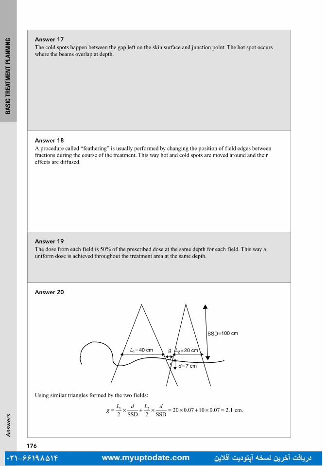
176
BASI
C TR
EATM
ENT
PLAN
NING
Ans
wer
s
Answer 19The dose from each field is 50% of the prescribed dose at the same depth for each field. This way a uniform dose is achieved throughout the treatment area at the same depth.
Answer 18A procedure called “feathering” is usually performed by changing the position of field edges between fractions during the course of the treatment. This way hot and cold spots are moved around and their effects are diffused.
Answer 17The cold spots happen between the gap left on the skin surface and junction point. The hot spot occurs where the beams overlap at depth.
Answer 20
Using similar triangles formed by the two fields:
= × + × = × + × =2 SSD 2 SSD
20 0.07 10 0.07 2.1 cm.1 2gL d L d
SSD =100 cm
d = 7 cm
L2= 20 cmgL1= 40 cm

177
BASI
C TR
EATM
ENT
PLAN
NING
Que
stio
ns
Question 23How much collimator rotation is necessary to match a cranial field to the upper spine field of Question 20?
Question 22What is the procedure to match the spinal and cranial fields?
Question 21The physician decides to treat a smaller area to avoid field matching. He would like to treat with one spinal field using an extended source to skin distance (SSD) technique because of field size limitation (maximum 40 cm × 40 cm). What should the new SSD be to treat an area of 50 cm at the skin surface?
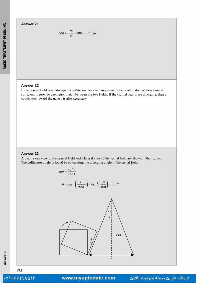
178
BASI
C TR
EATM
ENT
PLAN
NING
Ans
wer
s
Answer 22If the cranial field is nondivergent (half-beam block technique used) then collimator rotation alone is sufficient to provide geometric match between the two fields. If the cranial beams are diverging, then a couch kick toward the gantry is also necessary.
Answer 21
= × =SSD50
40100 125 cm.
Answer 23A beam’s eye view of the cranial field and a lateral view of the spinal field are shown in the figure. The collimator angle is found by calculating the diverging angle of the spinal field:
Lθ =tan/ 2
SSD1
SSD
θ
θ
L1
Ltan
2SSDtan
20
10011.51 1 1θ =
=
= °− −
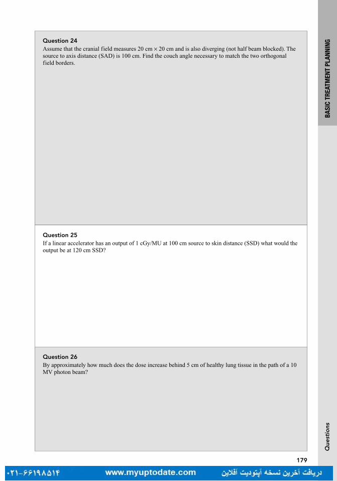
179
BASI
C TR
EATM
ENT
PLAN
NING
Que
stio
ns
Question 25If a linear accelerator has an output of 1 cGy/MU at 100 cm source to skin distance (SSD) what would the output be at 120 cm SSD?
Question 24Assume that the cranial field measures 20 cm × 20 cm and is also diverging (not half beam blocked). The source to axis distance (SAD) is 100 cm. Find the couch angle necessary to match the two orthogonal field borders.
Question 26By approximately how much does the dose increase behind 5 cm of healthy lung tissue in the path of a 10 MV photon beam?
180
BASI
C TR
EATM
ENT
PLAN
NING
Ans
wer
s
Answer 25Use the inverse square law:
Output at new SSD = (old SSD/new SSD)2 × output at old SSD
= (100/120)2 × 1 cGy/MU
= 0.694 cGy/MU.
Answer 24The angle of the couch kick is the angle of divergence of the cranial field, found by the formula tan−1(1/2 Field Size/SAD) = tan−1(10 cm/100 cm) = 5.7°.
L1L2
θ
Answer 26Approximately 10%. There is an increase in dose beyond healthy lung tissue by approximately 2% per cm of lung for a 10 MV photon beam.

181
BASI
C TR
EATM
ENT
PLAN
NING
Que
stio
ns
Question 30A physician wishes to treat a posterior spine with a field size of 10 cm × 50 cm on a linear accelerator with a maximum collimator opening of 40 cm × 40 cm at 100 cm source to skin distance (SSD). What is the minimum SSD that can be set to achieve the 10 × 50 field size?
Question 29A 24 cm × 20 cm field size is used to treat a patient’s pelvis at 100 cm source to axis distance (SAD) with parallel opposed fields to the midplane. The patient’s separation is 20 cm. Calculate the field size on the patient’s skin.
Question 28When using tangent fields to treat the breast and intra-mammary (IM) nodes, the medial field edge is set 3 cm to the contralateral side and the lateral field edge is set to encompass all of the breast tissue. If these fields result in inclusion of too much lung, what can be done to decrease the lung dose?
Question 27When treating a patient for breast cancer, what would decrease the scatter dose to the contralateral breast?
182
BASI
C TR
EATM
ENT
PLAN
NING
Ans
wer
s
Answer 2921.6 cm × 18 cmThis can be solved by similar triangles.24/100 = x/90 20/100 = y/90.
Answer 28The lung dose can be reduced by using a separate IM electron field that is matched with the tangents instead of using the wide tangent technique described earlier.
Answer 27To decrease the scatter dose to the contralateral breast, physical wedges on the medial tangent should be avoided.
Answer 30This can be solved by setting up a direct proportion40/100 = 50/required SSDRequired SSD = 125 cm.

183
BASI
C TR
EATM
ENT
PLAN
NING
Que
stio
ns
Question 34Per the International Commission on Radiation Units and Measurement (ICRU), what accuracy is necessary when delivering dose?
Question 33What are the definitions of “treated volume” and “irradiated volume”?
Question 32Based on International Commission on Radiation Units and Measurement (ICRU) target volume definitions, identify all target definitions in increasing volume order.
Question 31The dose rate in air is 111 cGy/min at 80 cm source to axis distance (SAD). The dose rate in tissue at the same point is 76 cGy/min. What is the tissue-to-air ratio (TAR)?
184
BASI
C TR
EATM
ENT
PLAN
NING
Ans
wer
s
Answer 34The ICRU mandates that dose calculations be accurate to a level of ±5% (American Association of Physicists in Medicine Task Group-71 [AAPM TG-71]).
Answer 33Treated volume is the volume enclosed by the prescription isodose line. Irradiated volume is the volume enclosed by 50% of the prescription isodose line.
Answer 32Gross tumor volume (GTV) < clinical target volume (CTV) < integrated target volume (ITV) < planning target volume (PTV). GTV is the visible tumor on imaging and the physical examination. The CTV is regions with concern for subclinical (microscopic) spread. The ITV adjusts for known motion in the tumor (eg, breathing). The PTV adjusts for random setup error.
Answer 31TAR is the ratio of the dose in tissue to the dose in air at the same point. Therefore, 76 cGy/min/111 cGy/min = 0.685.

185
BASI
C TR
EATM
ENT
PLAN
NING
Que
stio
ns
Question 36Which line likely represents the planning target volume (PTV) and the gross tumor volume (GTV)?
Question 35According to the dose volume histogram (DVH), what is the approximate V20 of the whole lung (black dashed)?
Dose Volume Histogram
Nor
mal
ized
Vol
ume
1.0
0.9
0.8
0.7
0.6
0.5
0.4
0.3
0.2
0.1
0.00 1000 2000 3000 4000 5000 6000 7000 8000
Dose (cGy)
Question 37What is the D90 of the planning target volume (PTV)?

186
BASI
C TR
EATM
ENT
PLAN
NING
Ans
wer
s
Answer 37The D90 of the PTV is the dose received by 90% of the PTV. In this case, it is 60 Gy.
Answer 36The gray-dashed line most likely represents the GTV and the black line represents the PTV, because a small fraction of the PTV does not receive the prescription dose of 60 Gy. As the GTV is within the PTV, the GTV must receive at least as much dose as the PTV.
Answer 35The V20 is the volume of the organ receiving 20 Gy, which in this DVH would be approximately 38%.

187
BASI
C TR
EATM
ENT
PLAN
NING
Que
stio
ns
Question 40What are the ways to match adjacent photon fields?
Question 39What is the four-field box technique?
Question 38How much of the whole lung receives 10 Gy or less in the dose volume histogram from Question 35? How much dose does 10% of the whole lung volume receive?
Question 41What are the main dose computation algorithms used by treatment planning systems?

188
BASI
C TR
EATM
ENT
PLAN
NING
Ans
wer
s
Answer 39The four-field box is a treatment planning technique where four fields, spaced 90° apart, from anterior, posterior, and lateral directions form a square or rectangular shape dose distribution, similar to a box shape. This was typically used to treat prostates before intensity-modulated radiation therapy (IMRT).
Answer 38From the dose volume histogram (DVH), 61% of whole lung receives 10 Gy or less dose. 10% of the whole lung receives 44 Gy.
Answer 40A typical method to match adjacent photon fields is to use half beams and match them at isocenter, where there is no beam divergence. Another way is to match the divergence of the beam by angling them away from each other, as is done in cranio spinal irradiation.
Answer 41The pencil beam, superposition convolution, and Monte Carlo algorithms. The pencil beam algorithm has been largely phased out due to its inability to accurately account for inhomogeneities, such as lung and other soft tissue.

189
BASI
C TR
EATM
ENT
PLAN
NING
Que
stio
ns
Question 44In a wedged pair, what direction are the wedges?
Question 43When treating a spine with anterior-posterior and posterior-anterior (AP/PA) fields, how are the fields weighted?
Question 42In 3 dimensional (3D) planning, when and how do you go “off cord”?
Question 45What are the typical field borders defined for treating the whole breast with two tangent fields?

190
BASI
C TR
EATM
ENT
PLAN
NING
Ans
wer
s
Answer 43Because the spine is located posteriorly, the PA field is weighted 60–70%.
Answer 42When treating a central target, it may be simplest to use anterior-posterior and posterior-anterior (AP/PA) fields, but this would irradiate the spinal cord as much as the target. To reduce the dose to the cord, an oblique, “off cord” field is typically added. The AP/PA fields are used to around 40 Gy, (below the cord tolerance) and then the off cord field is used.
Answer 44The wedges are planned so that their heels are together. A wedged pair is used to reduce the dose where the two beams overlap the most, at the shallowest depth.
Answer 45The typical field borders of the two tangent fields for treating the whole breast are:
Superior—1 cm above the breast tissue, which is usually just below the clavicular head.Inferior—2 cm below the inframammary line.Medial—The midline or midsternum.Lateral—The midaxillary line.

191
BASI
C TR
EATM
ENT
PLAN
NING
Que
stio
ns
Question 48How much does a Cerrobend block attenuate a typical beam? How many half-value layers (HVLs) of Cerrobend does this require?
Question 47What are the components of Cerrobend?
Question 46What is the density of Cerrobend relative to lead?
Question 49How are Cerrobend blocks shaped to minimize penumbra?
192
BASI
C TR
EATM
ENT
PLAN
NING
Ans
wer
s
Answer 4750% bismuth, 26.7% lead, 13.3% tin, 10.0% cadmium.
Answer 46Approximately 83% of the density of lead.
Answer 48Cerrobend can be sized to attenuate any amount of a beam, depending on its thickness. Typically, the block is designed to allow transmission of 5% or less. This requires n HVLs, where (1/2)n = 0.05, and therefore n = 4.3.
Answer 49Cerrobend blocks are “focused” toward the X-ray source by cutting them so that they match the divergence of the beam. When the blocks are cut, a Styrofoam mold is placed in a tray above a film (either a radiographic film or a digitally reconstructed radiograph [DRR]). A stylus, attached to a heated wire that anchors to a point the same distance from the Styrofoam as the source-to-block distance in the machine, is used to trace the outline of the planned block shape on the film below. The heated wire is thus angled to match the divergence of the beam originating from a source at that distance as it cuts through the Styrofoam. The cut Styrofoam is then used as a mold to pour the Cerrobend.

193
BASI
C TR
EATM
ENT
PLAN
NING
Que
stio
ns
Question 52What is the typical transmission through multileaf collimators (MLCs)?
Question 51How is penumbra minimized for multileaf collimators (MLCs)?
Question 50What are multileaf collimators (MLCs) made from?
Question 53What are the contributions to dose under a block?

194
BASI
C TR
EATM
ENT
PLAN
NING
Ans
wer
s
Answer 51Unlike cut Cerrobend blocks, MLCs are typically only focused in the direction perpendicular to the MLC movement but not focused in the direction parallel to the MLC movement (because most MLCs move in and out of the field in a straight line). The penumbra in the direction parallel to the MLC movement is thus larger than for a similarly shaped Cerrobend block. MLCs have rounded leaf edges to minimize partial transmission through the leaf edge. Blocks are also closer to the patient than MLCs, further reducing the penumbra.
Answer 50Tungsten.
Answer 52Depending on the manufacturer, transmission through MLCs is typically approximately 2% to 4% for interleaf transmission, 1% to 2% for intraleaf transmission, and 15% to 24% between leaf ends. 2% to 4% interleaf transmission includes the use of steps or tongue in groove arrangement in between leaves.
Answer 53There are two contributions, dose transmitted through the block, and dose scattered from outside the blocked region. The dose under the block is on the order of 10% of the unblocked dose, depending on the width of the block. A narrower block would allow more scatter under it.
195
BASI
C TR
EATM
ENT
PLAN
NING
Que
stio
ns
Question 56What is the definition of “hinge angle” for wedged fields?
Question 55If a 25-cm-thick patient is treated with anterior-posterior parallel-opposed fields prescribed to the midplane, which energy will have the smallest percentage variation between dose at the midplane and dose at D
max: 4 MV, 10 MV, or 16 MV?
Question 54A 20-cm-thick patient is being treated with anterior-posterior parallel-opposed fields prescribed to the midplane. At what depth is the dose highest?
Question 57A patient has a superficial soft tissue sarcoma and the decision is made to treat using a wedged pair oriented with a hinge angle of 60°. What is the optimum wedge angle for the wedged pair?

196
BASI
C TR
EATM
ENT
PLAN
NING
Ans
wer
s
Answer 55Higher energies have deeper penetration, which results in a more uniform dose distribution so 16 MV should be used.
Answer 54At a depth of D
max from the anterior and posterior skin surfaces.
Answer 56The hinge angle is the angle between the central axes of the two wedged fields.
Answer 57When two fields are angled at 60 degrees, there is a hotspot in the proximal corner. This can be reduced by adding wedges to each field. The wedges are oriented so that the heels are facing each other. The optimal wedge angle theta (θ) for any two fields oriented at angle phi (ϕ) is θ = 90 − ϕ/2. Therefore, θ = 90 − 60/2 = 60°.

197
BASI
C TR
EATM
ENT
PLAN
NING
Que
stio
ns
Question 60As field size increases, what happens to surface dose?
Question 59A patient has an esophageal tumor and the decision is made to treat to 50.4 Gy. What is the downside of using unweighted anterior-posterior and posterior-anterior (AP/PA) parallel-opposed fields? What is the downside of using a four-field technique?
Question 58A patient is being treated with a three-field technique to the pelvis for rectal cancer. If wedges are going to be used to compensate for the differential thickness of the patient from anterior to posterior, where will the heels of the wedges be placed?
Question 61As tray-to-skin distance decreases, what happens to surface dose?

198
BASI
C TR
EATM
ENT
PLAN
NING
Ans
wer
s
Answer 59The spinal cord will get a nearly full dose or above because the hotspots will be close to the surface of the patient. Conversely, a four-field technique will result in a higher dose to the lungs.
Answer 58Wedges are applied to the lateral fields with the heels pointed posteriorly, because the patient is typically thinner toward the sacrum than the umbilicus. This also reduces hotspots from the combination of the lateral fields and the posterior field.
Answer 60It increases. There will be more electron contamination of the beam due to scatter interactions with the collimator and air.
Answer 61It increases. Trays that are used to hold blocks are sources of electron contamination, and the closer the tray is to the surface, the less the opportunity for the electrons to scatter out of the field.

199
BASI
C TR
EATM
ENT
PLAN
NING
Que
stio
ns
Question 64What is the difference between bolus and a compensator?
Question 63What is one way of increasing surface dose without decreasing penetration at depth?
Question 62What happens to surface dose and d
max when using an oblique beam?
200
BASI
C TR
EATM
ENT
PLAN
NING
Ans
wer
s
Answer 63Use a beam spoiler, which is a plastic tray placed in the field close to the skin surface. The beam spoiler increases electron contamination but does not significantly attenuate the beam, therefore increasing the skin dose without decreasing penetration.
Answer 62Surface dose increases. The maximum increase is for a tangential field, where the skin dose is approximately four times that of a perpendicular field. d
max decreases. It is measured perpendicularly to the
skin and when the beam is oblique, it travels a longer path length to reach a particular perpendicular depth. Therefore, d
max occurs at a lower perpendicular depth than when the field is perpendicular to the skin.
Answer 64Bolus is a uniform thickness that is intended to increase dose to the patient’s skin. Compensators are intended to “compensate” for patients’ variable skin contours. Compensators are specially designed for each patient. A wedge is a type of compensator that compensates in only one direction and is not customized for each particular patient.

203
ELEC
TRON
TRE
ATM
ENT
Que
stio
ns
Question 4What is the field size dependence of R
90 and R
p?
Question 3What effect does changing the source-to-skin distance (SSD) have on the electron depth dose curve?
Question 2What is the practical range R
p for electrons?
Question 1How do electrons lose energy in a medium?
Turn page to see the answers.

204
ELEC
TRON
TRE
ATM
ENT
Ans
wer
s
Answer 4When the field size is above a threshold value, there is no depth dose variation. Below this threshold (which varies with beam energy), there can be significant variation. The depth of R
90 or range of 90% dose
is shifted increasingly toward the surface as field size decreases. Rp does not change with field size as it
reflects the energy of the beam only.
Answer 3The effect is fairly minimal due to the shallowness of the penetration of the electron beam. However, for higher energies the R
90 can be shifted distally a few mm as SSD increases.
Answer 2The practical range is the depth of electron penetration. It is the point at which the tangent to the descending portion of the depth dose curve intersects with the backward extrapolation of the bremsstrahlung tail. Practical range in cm is approximately ½ E(MeV).
Answer 1They lose energy through collisional interactions (ie, ionization and excitation) and radiative interactions (bremsstrahlung). In therapy, radiative losses only become significant at higher energies and high-Z materials.

205
ELEC
TRON
TRE
ATM
ENT
Que
stio
ns
Question 7What is the rough approximation for the useful depth for an electron beam as it relates to its energy?
Question 6What are some cases where skin collimation would be preferable to using a cutout?
Question 5How does the buildup region change with energy when using electrons?
Question 8An electron beam will be used to treat a tumor whose most distal depth is 4.8 cm. Assume there are no critical structures beyond the tumor. What energy should be used?

206
ELEC
TRON
TRE
ATM
ENT
Ans
wer
s
Answer 8Typically, the tumor should be covered by the 90% isodose line. A rule of thumb for determining the energy to use is
Ep,0
~ 3.3 × R90
(cm)
So in the example the energy selected would be 3.3 × 4.8 = 15.8, so a 16 MeV beam should be selected. To cover with the 80% isodose line, the rule of thumb is
Ep,0
~ 3 × R80
(cm)
and so the energy would be 3 × 4.8 = 14.4 or 15 MeV.
Answer 7The useful depth in cm is the approximate point where the 80% to 90% isodose line occurs:D80(cm) ~ 1/3 E(MeV) or D90(cm) ~ E(MeV)/3.3. Note that E/4 has also been used to approximate D90. It is important to check percent depth dose curves (PDDs) for specific field size to choose the right energy for depth of treatment required.
Answer 6The primary benefit of skin collimation is a much sharper penumbra compared with a cutout. This is useful for:
• Small field treatments• Providing maximal protection to adjacent critical structures• Reducing penumbra beneath a bolus• Reducing penumbra beneath an extended air gap• Reducing penumbra in electron arc therapy
Answer 5The surface dose increases with beam energy, from approximately 75% to 95%. Skin sparing is minimal with electrons, and almost nonexistent at higher energies. This is in contrast to photons where surface dose decreases with increasing beam energy.

207
ELEC
TRON
TRE
ATM
ENT
Que
stio
ns
Question 9Where does the X-ray contamination of an electron beam come from, and how does it vary with energy?
Question 11How would the depth dose for a rectangular field of width L × W be determined, if the depth doses for square fields L × L and W × W are known?
Question 10Why is bolus used in electron therapy and what kind of material is bolus made from?
Question 12Electron beams are ideally treated en face, or perpendicular to a flat patient surface. What is the effect of treating on a sloped, or oblique, skin surface?
208
ELEC
TRON
TRE
ATM
ENT
Ans
wer
s
Answer 12Treating on an oblique surface creates: increased surface dose, a higher maximum dose, a shift in R
90
toward the surface, and an increase in Rp.
These changes are most significant at angles of obliquity >30°.
Beam obliquity increases side scatter at the point of maximum dose, increases the depth of penetration of the beam, and moves D
max deeper into the patient.
Answer 11At a given depth d,
× = × × ×D d L W D d L L D d W W% ( , ) % ( , ) % ( , )
Answer 10Bolus is used to: (1) reduce surface irregularities, (2) limit the penetration of the electron beam in certain places, and (3) increase the surface dose. Bolus is made of a tissue equivalent Z material. Commonly used bolus materials include wax, paraffin gauze, superflab, and other pliable plastics.
Answer 9The X-ray contamination of an electron beam results from bremsstrahlung interactions within the linac head (scattering foils, ion chambers, collimator jaws, etc.) and in patient tissues. Contamination increases with increasing energy, typical values are: 0.5% to 1% for 6 to 12 MeV, 1% to 2% for 12 to 15 MeV, and 2% to 5% for 15 to 20 MeV.

209
ELEC
TRON
TRE
ATM
ENT
Que
stio
ns
Question 16What would be the effect of having 2 cm of bolus covering only part of the electron field?
Question 15What is the effect of treating a protuberance (such as the nose), or a cavity (such as near the external audi-tory meatus)?
Question 14What is the effect of treating through bone?
Question 13What is the effect of treating through an air cavity? What should be done to mitigate this effect when treating through nasal passages?

210
ELEC
TRON
TRE
ATM
ENT
Ans
wer
s
Answer 16The edge of the bolus would act like a protuberance, causing a hot spot just outside the bolus and a cold spot inside the bolus. This should be avoided by tapering the edge of the bolus.
Answer 15Surface irregularities and internal heterogeneities such as these can lead to a complex dose distribution with hot and cold spots. Typically for a protuberance the hot spots will be on either side of the protuberance, and a cold spot behind it. The base of a cavity will be hot while its sides will be cold. Bolus can help to alleviate these issues.
Answer 14The dose directly distal to the bone is decreased. The dose lateral and distal to the bone is increased. Again, both of these effects are due to loss of side-scatter equilibrium. With bone, there is more scatter out of the bone than into the bone. This is the opposite case to air where more radiation scatters into the air cavity than out of the cavity.
Answer 13The dose distal to the air cavity is increased. The dose lateral and distal to the air cavity is decreased (both effects are due to loss of side-scatter equilibrium). Also, the range of the electrons is increased due to lost attenuation. When treating through nasal passages (eg, the nasal septum), nose plugs should be used to replace the lost scattering medium.

211
ELEC
TRON
TRE
ATM
ENT
Que
stio
ns
Question 20In electron arc therapy, the air gap from the secondary collimator to the patient is typically larger than normal. What issue does this cause, and how is it remedied?
Question 19How is treatment planning achieved when intraoperative irradiation is performed?
Question 18What is the most common approach for minimizing the hot and cold spots that result from abutting electron fields?
Question 17What are the two primary considerations in designing internal collimation/shielding?

212
ELEC
TRON
TRE
ATM
ENT
Ans
wer
s
Answer 20The large air gap causes a large penumbra. This is fixed by using skin collimation to sharpen the penumbra, and rotating the arc approximately 15° beyond the edge of the treatment area.
Answer 19Planning takes place in a surgical setting where it is not possible to CT the patient in the treatment position. Therefore manual calculations are performed, based on estimation of depth, and fields shaped using lead.
Answer 18The degree of heterogeneity is reduced by feathering the beam edge by ±1 cm over the course of treatment.
Answer 17First, the collimator must be sufficiently thick to stop the radiation. Second, backscatter from the collimator can be significant and must be taken into account by coating the shield with plastic, wax, or ceramic.

213
ELEC
TRON
TRE
ATM
ENT
Que
stio
ns
Question 24How does electron backscatter vary with both atomic number and energy?
Question 23Why must electron isodose curves be calculated for each machine for the same energy and field sizes?
Question 22Which of the following increase with increasing energy: surface dose, depth of D
max, depth of 90% isodose
line, practical range, and bremsstrahlung contamination?
Question 21What is the rule of thumb when designing the shape of the cutout aperture?

214
ELEC
TRON
TRE
ATM
ENT
Ans
wer
s
Answer 24Backscatter increases with increasing atomic number and decreases with increasing electron energy.
Answer 23Scattering of electrons by different physical components in the electron beam (see Question 9).
Answer 22All of these increase with increasing energy except for D
max depth, which varies irregularly with energy
and machine type.
Answer 21Typically there is about a 1-cm margin between the edge of the cutout and the edge of the target volume when both are projected to isocenter.

215
ELEC
TRON
TRE
ATM
ENT
Que
stio
ns
Question 28What are the relative electron densities of compact bone, spongy bone, and lung?
Question 27What are the three significant regions in an electron depth dose distribution?
Question 26When using electron shields on a patient, what must you account for?
Question 25How does one determine the dose at a point when using electron arc therapy?

216
ELEC
TRON
TRE
ATM
ENT
Ans
wer
s
Answer 28The relative electron densities are 1.6, 1.1, and 0.2, respectively.
Answer 27(1) Buildup region caused by side-scattered electrons, which increases with electron energy, (2) regions of sharp dose falloff, beginning around the 90% isodose, and (3) the tail due to bremsstrahlung, the magnitude of the tail increases with increasing energy.
Answer 26The shield causes electron backscatter, which increases tissue dose proximate to the shield. As a result, it is important to cover the shield with a filter of a lower atomic number than the shield (eg, wax or plastic on eye shields).
Answer 25One could measure the dose at a point in a cylindrical phantom or integrate the isodose distribution for the arc at a point.

217
ELEC
TRON
TRE
ATM
ENT
Que
stio
ns
Question 32When might you use the virtual source of an electron beam?
Question 31What is the virtual source of an electron beam?
Question 30How do you determine the thickness of lead when making blocks to shape electron fields?
Question 29How deep will a 6 MeV beam reach into the lung if there is 1 cm of tissue, 0.5 cm of compact bone, and then 10 cm of lung?

218
ELEC
TRON
TRE
ATM
ENT
Ans
wer
s
Answer 32To calculate the virtual source to skin distance (SSD) for estimation of output at extended SSD using inverse square.
Answer 31Unlike a photon beam, which has a distinct focus originating at the X-ray target, an electron beam behaves differently. It appears to originate from a virtual point in space, which can change depending on beam energy and field size. Measurements taken at different distances and plotted on a graph can be used to determine the virtual source position, which is typically just upstream of the scattering foil.
Answer 30The rule of thumb is T(lead) mm = 0.5 mm/MeV. Sometimes 1 mm can be added to the thickness for safety. Cerrobend is around 20% less dense than lead, so T(Cerrobend) = 1.2 × T(lead).
Answer 29The range of a 6 MeV beam in water is 3 cm. The initial tissue is equivalent to 1 cm of water. The compact bone is 0.5 cm with a relative electron density of 1.6, therefore the effective depth in water is 0.5 × 1.6 = 0.8 cm of water. The beam therefore has 3 − 1 − 0.8 = 1.2 cm of water range remaining. The range in lung is the range in water divided by the relative electron density of lung 1.2/0.2 = 6 cm.

219
ELEC
TRON
TRE
ATM
ENT
Que
stio
ns
Question 36What is the difference in the isodose lines for an en face electron beam with regards to the difference between the high (90%) and low (20%) lines?
Question 35What is the energy of a 12 MeV beam at 2 cm depth in water?
Question 34What is the energy spectrum of an electron beam as it leaves the accelerator and reaches the patient?
Question 33An electron cone has an output of 1.13 cGy/MU at d
max. How many MU are needed to deliver 200 cGy to
the 90% isodose level?

220
ELEC
TRON
TRE
ATM
ENT
Ans
wer
s
Answer 36For an electron beam, high isodose lines bow inward, creating a smaller region receiving the prescription isodose at depth than the field size at the surface. Conversely, the low isodose lines bow outward.
Answer 35
E = E0(1 − depth/R
p)
= 12(1 − 2/6) Rp = 12/2 (refer to Question 2)
= 8 MeV
Answer 34As an electron beam leaves the accelerator, it is practically monoenergetic. On its way to the patient, it interacts with scattering foils, collimators, air, and other structures, resulting in a broadening of the energy spectrum. The mean energy at the patient’s surface is lower than that of the initial beam created inside the linear accelerator.
Answer 33The basic formula for calculating MUs is:
MU = ×Dose
Output factor Isodose line
= 200/(1.13 × 0.90)= 197

221
ELEC
TRON
TRE
ATM
ENT
Que
stio
ns
Question 40A physician wants to treat to 3.5 cm depth with electrons, but avoid a critical structure which is 6.5 cm deep. The available electron energies are 6, 9, 12, and 15 MeV. What energy would you use?
Question 39When are electrons used in breast irradiation?
Question 38What are common treatment sites for electrons?
Question 37Where is the hotspot when a 9 MeV electron beam is abutted to a 6 MV photon beam?
Question 41When placing bolus on the skin, why must it be placed directly on the skin?

222
ELEC
TRON
TRE
ATM
ENT
Ans
wer
s
Answer 40To treat to the 90% isodose line, E = 3.5 × 3.3 = 11.55 MeV. Electron energy of 13 MeV is required to reach a depth of 6.5 cm. Therefore a 12 MeV beam would cover the target, but not reach the critical structure.
Answer 39Electrons are used in the treatment of Internal Mammary Chain (IMC) nodes, chest wall post mastectomy, and tumor bed boosts.
Answer 38Electrons are often used to treat superficial tumors of the skin (eyelids, nose, scalp, ear, etc.), shallow tumors, tumor beds, and scar boosts.
Answer 37The isodose lines of electron beams tend to bulge outward at depth, leading to hot and cold spots. If the beams are matched at the skin, the electron beam will bulge into the photon beam at depth and create a hotspot.
Answer 41Air gaps between skin and bolus will result in a decreased dose and increased penumbra as a consequence of the bolus scattering the electrons, which then can travel out of the field in the air gap.
8BRACHYTHERAPY
MARIA RYBAK, NEIL WOODY, AND ALLAN WILKINSON
8.1 BRACHYTHERAPY 225
8.2 LOW-DOSE-RATE BRACHYTHERAPY 235
8.3 HIGH-DOSE-RATE BRACHYTHERAPY 245

225
BRAC
HYTH
ERAP
Y8
.1 B
rach
ythe
rap
y •
Que
stio
ns
Question 4What are permanent versus temporary implants in brachytherapy?
Question 3What are different types of brachytherapy loading systems?
Question 2What are the types of brachytherapy?
Question 1 8.1 BRACHYTHERAPYWhat is brachytherapy?
Turn page to see the answers.

226
BRAC
HYTH
ERAP
Y8
.1 B
rach
ythe
rap
y •
Ans
wer
s
Answer 4Permanent implants—the radioactive sources are permanently implanted into the tumor, the patient is released from the hospital with radioactive materials in them.Temporary implants—the radioactive material is implanted into or close to the tumor and is removed once the prescribed radiation dose has been delivered.
Answer 3Manual “hot” loading: used for low dose rate seeds such as prostate or eye plaque.Manual afterloading: this technique is not frequently used anymore.Remote afterloading: most frequently used for high dose rate treatment.
Answer 2Interstitial brachytherapy—radioactive sources are placed in the target tissue directly either permanently or temporarily.Intracavitary brachytherapy—radioactive sources are contained in an applicator that is inserted into body cavities such as the vagina or uterus.Intraluminal brachytherapy—subclass of intracavitary brachytherapy in which the radioactive sources are inserted in the lumen of the patient such as the blood vessel, bronchus, esophagus, or bile duct.Surface–Radioactive sources (or seeds) are placed in the surface plaques or molds, which are then placed on the treatment area such as the eye or skin.
Answer 1Brachytherapy is a special procedure in Radiation Oncology that uses radioactive sources placed at short distances (hence brachy) from the target. Brachytherapy generates highly conformal dose distributions in a target volume because radioactive seeds (or sources) are placed directly within or in the vicinity of the target tissue.

227
BRAC
HYTH
ERAP
Y8
.1 B
rach
ythe
rap
y •
Que
stio
ns
Question 7What types of radiation are used in brachytherapy?
Question 6What radionuclides are currently most used for brachytherapy treatments?
Question 5What are the dose rate ranges for low-, medium-, and high-dose-rate brachytherapy according to Interna-tional Commission for Radiation Units and Measurements (ICRU) Report No. 38?
Question 8How is radiation source strength typically specified in clinic?
228
BRAC
HYTH
ERAP
Y8
.1 B
rach
ythe
rap
y •
Ans
wer
s
Answer 8For photon emitters, air kerma strength (U) is commonly used; for electron emitters, Becquerel (usually MBq or GBq) is typically used. Curie (Ci) and mCi are older units that are still commonly used for photon emitters.
Answer 7Photons, electrons (betas), and rarely neutrons (Cf-252) and alpha particles are used.
Answer 6Gamma emitters: Cs-137 and Ir-192 for high energy gammas, or I-125 and Pd-103 for low energy gammasBeta emitters: P-32, Ru-106, Sr-90, and Y-90.
Answer 5Low-Dose-Rate (LDR): 0.4 to 2.0 Gy per hour—used for permanent and manually afterloaded brachytherapyMedium-Dose-Rate (MDR): 2 to 12 Gy per hour. Pulsed dose rate (PDR) brachytherapy afterloaders were developed in this dose rate realm to replicate the LDR experience in terms of total treatment duration but with the source exposed in pulses for only 5 to 10 minutes per hourHigh-Dose-Rate (HDR): more than 12 Gy per hour—HDR brachytherapy utilizes very high activity sources, typically a 10 Ci Ir-192 source. Treatment is delivered by remote-control techniques. The usual dose rate is about 100 to 300 Gy per hour.
229
BRAC
HYTH
ERAP
Y8
.1 B
rach
ythe
rap
y •
Que
stio
ns
Question 9You receive an Ir-192 seed with an air kerma strength of 6.25 µGy m2/h. What is the strength of the source in mg-Ra equivalent?
Question 11What are the physical states of radionuclides used in brachytherapy?
Question 10The apparent activity for the Ir-192 source is measured to be 20 mCi. Calculate the air kerma strength in cGy cm2/h (The exposure rate constant of Ir-192 is 4.69 R cm2/mCi h).
Question 12What are the advantages of the high-dose-rate (HDR) brachytherapy compared with low-dose-rate (LDR) brachytherapy?
230
BRAC
HYTH
ERAP
Y8
.1 B
rach
ythe
rap
y •
Ans
wer
s
Answer 12Out-patient procedureSafety—reduction or elimination of radiation exposure to the radiation therapy staffOptimization—moving source allows optimization of the dose distribution by adjustment of the dwell times for each dwell position in each channel (catheter or needle), permitting very fine control of the dose distributionStability—HDR intracavitary treatments take less time (usually under an hour), and the movement of the applicators during treatment is minimized.Dose reduction to normal tissue—shorter duration of HDR treatments allows for physical displacement of normal tissue structure during treatmentApplicator size—the small size of the HDR source permits the use of smaller applicators
Answer 11Solids, liquids, and gases (Xe-133). Solid sources are sealed (encapsulated in a metal shell).
Answer 10Air kerma strength = Exposure rate constant (R cm2/mCi h) × Apparent activity (mCi) × Roentgen to cGy
conversion factor for air of 0.876 cGy/R= 4.69 R cm2/mCi h × 20 mCi × 0.876 cGy/R= 82.2 cGy cm2/h
Answer 91 mg-Ra equivalent is defined as 8.25 × 10⁻⁴ R/h. Using the Roentgen to rad conversion factor for air 0.876 rad/R and converting Rad (cGy) to µGy, we obtain 8.76 × 10³ µGy/R.Thus 1 mg-Ra eq at 1m = 8.25 × 10⁻⁴ R/h × 8.76 ×10³ µGy/R = 7.23 µGy m2/hDividing the air kerma strength of our source by this conversion factor gives us the result. 6.25/7.23 = 0.864 mg-Ra eq.

231
BRAC
HYTH
ERAP
Y8
.1 B
rach
ythe
rap
y •
Que
stio
ns
Question 16What is anisotropy with respect to radioactive sources?
Question 15What is the current method for calculating dose rate in tissue from a radioactive source?
Question 14What are the safety features and operational interlocks of the high-dose-rate (HDR) afterloader?
Question 13What are the disadvantages of the high-dose-rate (HDR) brachytherapy compared with low-dose-rate (LDR) brachytherapy?
232
BRAC
HYTH
ERAP
Y8
.1 B
rach
ythe
rap
y •
Ans
wer
s
Answer 16Anisotropy refers to the directional dependence of the fluence from a source due to the location of the radioactive material within the source and differences in wall thickness and construction.
Answer 15The TG-43 formalism with no heterogeneity corrections is the current standard.
Update of AAPM Task Group No. 43 Report: a revised AAPM protocol for brachytherapy dose calculations. Med Phys. 2004;31:633–674.
Answer 14Audio/visual systemRadiation monitors and treatment on indicatorDoor interlockEmergency shut-offsEmergency crankBackup battery
Answer 13Investment—machine’s cost can be anywhere between $1M and $2M.Radiobiology—as the dose rate increases, the radiosensitivity (damage per unit dose) increases for both normal tissues and tumors, the radiosensitivity for the normal tissue increases faster, increasing the likelihood of injuring the patient while controlling the tumor. Overcoming this requires the use of the advantages of optimization, geometry, stability, and dose reduction to normal tissues, and multiple fractionation treatment.Safety—if the HDR machine has a malfunction or if a patient has an emergency situation, the risk of accidental radiation exposure to the patient and the staff is much higher in HDR than in LDR.

233
BRAC
HYTH
ERAP
Y8
.1 B
rach
ythe
rap
y •
Que
stio
ns
Question 20What are the requirements regarding calibration of new sources?
Question 19What instrument would you use to survey a patient before release?
Question 18What instrument would you use to locate a missing source?
Question 17What is the main determinant of the dose rate from a source?
234
BRAC
HYTH
ERAP
Y8
.1 B
rach
ythe
rap
y •
Ans
wer
s
Answer 20New sources must be calibrated before treating patients using a dosimetry system that has a National Institute of Standards and Technology (NIST) traceable calibration. The dosimetry system typically comprises a well-chamber and an electrometer capable of reading in the current mode. For the source activity in mCi range, the typical current readings from the electrometer are on the order of 10−11 A (ampere). For an HDR source (about 10 Ci activity), the current is 10-7 A. This current is then converted into the activity of the source.
Answer 19A sensitive, calibrated ion chamber (eg, one with a large, pressurized gas-filled chamber) is typically used.
Answer 18A Geiger–Muller (GM) counter.
Answer 17For distances greater than a few mm, it is the inverse square factor.
235
BRAC
HYTH
ERAP
Y8
.2 L
ow
-Do
se-R
ate
Bra
chyt
hera
py
• Q
uest
ions
Question 22What are the rules regarding a radioactive materials (RAM) inventory?
Question 21What are the corrections applied to the electrometer readings when performing a calibration check?
Question 1 8.2 LOW-DOSE-RATE BRACHYTHERAPYWhat isotopes are used for permanent implants and what are the reasons for choosing them?
Question 2What are the typical dosimetric parameters for a prostate implant?

236
BRAC
HYTH
ERAP
Y8
.2 L
ow
-Do
se-R
ate
Bra
chyt
hera
py
• A
nsw
ers
Answer 22The Nuclear Regulatory Commission (NRC) requires a licensee to maintain an inventory log for all radioactive materials. The log must contain the type of source (isotope), source strength, and its location. Permanent sources implanted in a patient are not subject to this inventory control once the patient has been released from the facility.
Answer 21If the well chamber is open to the atmosphere, as most are, a temperature and pressure correction must be applied. In addition, there may be an electrometer scale reading correction.
Answer 1The isotopes most commonly used are I-125, Pd-103, and Cs-131. They are used because of their low average photon energies (0.028, 0.021, and 0.029 MeV) so that they will treat only the tumor, and have relatively short half-lives (59.4, 17, and 9.7 days).
Answer 2For I-125, the prescription dose is 144 Gy to cover the prostate delineated on the ultrasound images. V150 (volume of the prostate receiving 150% of the prescription dose of 144 Gy) values ranging from 40% to 50% of the prostate and V200 from 10% to 20% of the prostate are acceptable. Although there may be no explicit margin contoured, the implant volume receiving 144 Gy is approximately twice that of the prostate itself. For Pd-103, the prescription dose is 125 Gy.

237
BRAC
HYTH
ERAP
Y8
.2 L
ow
-Do
se-R
ate
Bra
chyt
hera
py
• Q
uest
ions
Question 4What is the release criterion for a prostate seed implant patient?
Question 3What are the simplifications in the TG-43 calculation used for prostate implants?
Question 5What is the purpose of postimplant dosimetry?
Question 6A patient undergoes a low-dose-rate (LDR) prostate brachytherapy implant with Pd-103 to a prescription dose of 125 Gy. What is the initial dose rate (cGy/h) of the implant?

238
BRAC
HYTH
ERAP
Y8
.2 L
ow
-Do
se-R
ate
Bra
chyt
hera
py
• A
nsw
ers
Answer 4Per Nuclear Regulatory Commission (NRC) regulations (hence also agreement states), “a licensee may authorize the release from its control of any individual who has been administered unsealed radioactive material or implants containing radioactive material if the total effective dose equivalent to any other individual from exposure to the released individual is not likely to exceed 5 millisieverts (0.5 rem).” For prostate patients, this is satisfied if the exposure rate measured at 1 m from the patient is <1 mR/h.
Answer 3Per Radiation Therapy Oncology Group (RTOG) protocols, the source is modeled as a point and the anisotropy as a function of distance (r) only with no directional information about seed orientation within the implant.
Answer 5CT-based postimplant dosimetry is usually conducted roughly 30 days after a prostate seed implant procedure. This allows for gland swelling due to edema to subside. The postimplant dosimetry is primarily performed as a quality assurance measure for the implant procedure. It has also been used for regulatory purposes (ie, defining a “medical event”).
Answer 6The initial prescription dose will be equal to the total dose (125 Gy)/the average life of the source. The average life is: 1.44 times the half-life, so for Pd-103: T
average = 17 days × 24 hours/day × 1.44 or 587.5
hours. Therefore dose rate is 125 Gy/587.5 hours = 21.3 cGy/h. By comparison, the initial dose rate for an I-125 implant of 144 Gy is about 7 cGy/h, which is lower due to its longer half-life.

239
BRAC
HYTH
ERAP
Y8
.2 L
ow
-Do
se-R
ate
Bra
chyt
hera
py
• Q
uest
ions
Question 8What brachytherapy procedure is used for treating ocular lesions?
Question 7Describe a prostate seed implant procedure?
Question 9Describe the eye plaques in current clinical use.
Question 10How is the dose specified and calculated for eye plaque treatments?

240
BRAC
HYTH
ERAP
Y8
.2 L
ow
-Do
se-R
ate
Bra
chyt
hera
py
• A
nsw
ers
Answer 8Uveal melanoma and retinoblastoma may be treated using a surface plaque containing radioactive material (typically I-125, Ru-106, Pd-103, or Cs-131). Melanomas are treated with a prescription dose of 85 Gy in 3 or 4 days; retinoblastomas with a prescription dose of 40 to 45 Gy in 2 days. The plaque also shields the eye cavity from radiation.
Answer 7The patient is placed in the dorsal lithotomy position under general anesthesia. Radioactive sources are implanted through the perineum using preloaded needles containing either loose seeds or seeds in a strand. Radioactive seeds are spaced at least 1 cm apart in the needle. The number of needles needed for an implant depends on the volume of the prostate. The needles are typically arranged to provide a modified peripheral loading, resulting in fewer sources in the center of the prostate near the urethra. The needles are inserted through a special template that is attached to a transrectal ultrasound probe. Seeds may also be implanted using a Mick applicator.
Answer 9Collaborative Ocular Melanoma Study (COMS, begun in 1986) plaques consisting of a gold shield with a silastic insert containing the I-125 seeds as well as Eye Physics gold plaques with embedded seeds are used. There are COMS plaques available with a notch to facilitate placement near the optic nerve.
Answer 10The Collaborative Ocular Melanoma Study (COMS) dose is 85 Gy to 5 mm or the tumor apex, whichever is greater. Treatment times are typically around 100 hours. For COMS, the dose was calculated using a point model for the seed and no anisotropy or heterogeneity correction. Current AAPM (the American Association of Physicists in Medicine) recommendations are to use a line-source approximation and calculate for homogeneous water media. Included in the Task Group (TG) report 129 are data for heterogeneous corrections. Software such as Plaque Simulator modifies the calculation by accounting for silastic carrier attenuation and changes in scatter due to the gold shield.
The American Brachytherapy Society recommendations for brachytherapy of uveal melanomas. Int J Radiat Oncol Biol Phys. 2003;56:544–555.
Dosimetry of 125 I and 103 Pd COMS eye plaques for intraocular tumors: report of task group 129 by the AAPM and ABS. Med Phys. 2012;39(10).

241
BRAC
HYTH
ERAP
Y8
.2 L
ow
-Do
se-R
ate
Bra
chyt
hera
py
• Q
uest
ions
Question 12What radiation safety precautions are taken regarding eye plaque patients?
Question 11What are the regulations regarding seed activity assays?
Question 13What radiation safety precautions are taken for prostate implant patients?
Question 14What is the primary goal and key features of the Patterson–Parker (Manchester) system of interstitial implants?

242
BRAC
HYTH
ERAP
Y8
.2 L
ow
-Do
se-R
ate
Bra
chyt
hera
py
• A
nsw
ers
Answer 12Patients remain in the hospital for the duration of the therapy. The room in which they are housed requires a radiation sign posted on the outside of the room; the patients wear special leaded glasses that reduce radiation exposure levels by a factor of 5 to 6 when visitors or nursing staff are present. Nursing staff require annual radiation safety training. Following patient discharge, the room and contents are surveyed for radioactive material.
Answer 11The Nuclear Regulatory Commission (NRC) and hence agreement states require a 10% independent assay to confirm the accuracy of the specified seed activity. The assay may be performed by a third party, but the AAPM (the American Association of Physicists in Medicine) recommends that a check be done at the local institution.
Answer 13Following the operating room implant procedure, the patient is taken to a recovery area. He is provided with a urinal for his use. After discharge (typically a few hours), the urinal and patient bedding are checked for radioactive sources. If any sources are found, they are stored in a locked cabinet until removal by Radiation Safety. Patients with permanent implants are provided with a small card indicating the date and nature (isotope, total activity) of the implant and a document of precautions to be followed to minimize exposure to others.
Answer 14The primary goal is to deliver a uniform dose to a plane or volume in parallel planes 0.5 cm from the implanted plane(s) (within +/− 10% of the prescribed dose). To achieve this goal, the system uses specified rules for distribution of sources and activity. For a planar implant the smaller the treated area the greater the fraction of the amount of Radium (or equivalent) to be placed at the periphery. The implant volume is determined and tables are used to determine the milligram hours of Radium per 1,000 roentgens. Note that the tables employed the historical exposure rate constant (Γ) for Radium (8.4 R cm2/mg-h) instead of the current value for Radium Γ = 8.25 R cm2/mg-h and thus the tables truly reflect milligram hours of Radium per 900 cGy.

243
BRAC
HYTH
ERAP
Y8
.2 L
ow
-Do
se-R
ate
Bra
chyt
hera
py
• Q
uest
ions
Question 16What is the goal of the Paris system and its key features?
Question 15How does the Quimby system differ in their goal and source loading from the Patterson–Parker system?
Question 17What sources can be employed with the Patterson–Parker and Quimby systems?
Question 18What has largely supplanted systems such as Patterson–Parker in modern interstitial brachytherapy planning?

244
BRAC
HYTH
ERAP
Y8
.2 L
ow
-Do
se-R
ate
Bra
chyt
hera
py
• A
nsw
ers
Answer 16The Paris system prescribes dose to an isodose surface (reference isodose). Like the Quimby system uniform sources placed in parallel lines are employed.
Answer 15The goal of the Quimby system is to calculate the maximum dose in the center of the treatment plane at a distance of up to 3 cm. The system relies on a uniform distribution of sources of equal linear activity. By comparison the Patterson–Parker system uses nonuniform distributions and may employ varied source activities to achieve a uniform dose to a plane(s).
Answer 17Both systems were designed for Radium implants. Isotopes similar to Radium (Radium equivalents) Ir-192 and Cs-137 can be calculated but these systems are not compatible with lower energy brachytherapy sources such as I-125.
Answer 18Computerized calculation of doses delivered with summation of doses to each point from all contributing sources. Furthermore use of afterloading systems allow for evaluation of the plan with dummy sources in place and active source placement after the plan has been evaluated.
245
BRAC
HYTH
ERAP
Y8
.3 H
igh-
Do
se-R
ate
Bra
chyt
hera
py
• Q
uest
ions
Question 4What are the advantages and disadvantages of Cs-137 as high-dose-rate (HDR) brachytherapy source rela-tive to Ir-192?
Question 3What are the steps for initiating a high-dose-rate (HDR) procedure?
Question 2What is the Nuclear Regulatory Commission (NRC) limit on leakage levels for high-dose-rate (HDR) units?
Question 1 8.3 HIGH-DOSE-RATE BRACHYTHERAPYWhat is the most common high-dose-rate (HDR) brachytherapy source, its half-life, dimensions and typi-cal activity?

246
BRAC
HYTH
ERAP
Y8
.3 H
igh-
Do
se-R
ate
Bra
chyt
hera
py
• A
nsw
ers
Answer 4Cs-137 has a higher average energy than Ir-192 that could be beneficial for improved percent depth dose, but higher energies are accompanied by higher shielding requirements. Cs-137 has a longer half-life requiring less frequent replacement than Ir-192. However, Cs-137 has lower specific activity requiring a larger source and hence larger catheters.
Answer 3The following steps must be completed to be compliant with the Nuclear Regulatory Commission (NRC):
1. Authorized physician user must sign the complete written directive2. Patient is identified and verified by two methods3. Treatment plan must be checked by a medical physicist4. Pretreatment HDR unit safety checks must be completed5. Prior to treatment delivery the authorized user must verify patient and treatment detail6. Treatment must be supervised from start to end by authorized user and treatment records
must be recorded7. A postdelivery survey must be completed8. Medical events must be recorded and reported9. Periodic reviews at least yearly are performed and source and calibration is performed and recorded
Answer 2Leakage may not exceed 1 mR/h at a distance of 10 cm from the nearest accessible surface of the safe when the source is in the shielded position.
Answer 1Iridium-192 is the most common HDR brachytherapy source. Ir-192 has a half-life of 74.4 days and a mean energy of 380 keV. A typical source is 0.3 to 0.6 mm in diameter and 3.5 to 10 mm in length with an initial activity of ~10 Ci.
247
BRAC
HYTH
ERAP
Y8
.3 H
igh-
Do
se-R
ate
Bra
chyt
hera
py
• Q
uest
ions
Question 8In vaginal cuff brachytherapy treatment for endometrial cancer what is the preferred vaginal cylinder diameter?
Question 7What is the most commonly used applicator for treatment of endometrial cancer?
Question 6Why is high-dose-rate (HDR) brachytherapy used for the treatment of endometrial cancer?
Question 5You have a brachytherapy source with a half-value layer (HVL) of 2 cm of lead. You are doubling the usage of this source. On one side of the high-dose-rate (HDR) suite is a bathroom and on the other side a hallway (occupancy factor ¼) that is being converted into a work area (occupancy factor 1). To maintain safe shielding levels, how many cm of lead if any should be added to the wall facing the bathroom and to the wall facing the new work area?
248
BRAC
HYTH
ERAP
Y8
.3 H
igh-
Do
se-R
ate
Bra
chyt
hera
py
• A
nsw
ers
Answer 8The largest diameter cylinder that can reasonably fit for the patient should be used. The larger cylinder provides a more uniform dose distribution as the diameter of the cylinder increases.
Answer 7The vaginal cylinder applicator is most commonly used. Cylinders come in a variety of diameters (2–4 cm) and lengths to better conform to the patient’s anatomy. The cylinder should closely fit to the superior aspect of the vaginal cuff and contact the lateral surfaces of the vagina.
Answer 6The vast majority of patients undergo curative hysterectomies, however, with no further therapy approximately 12% of the patients are likely to suffer recurrences. Patients who received prophylactic radiation to the vaginal cuff had much reduced recurrences.
Answer 5Since the usage of the source is set to double one HVL (2 cm of lead) should be applied to all walls to maintain current shielding levels. In addition for the wall facing the new work area where the occupancy factor has increased fourfold, two additional HVL (4 cm) of shielding should be added to this wall. Therefore 2 cm on the bathroom side and 6 cm on the work area site are needed.

249
BRAC
HYTH
ERAP
Y8
.3 H
igh-
Do
se-R
ate
Bra
chyt
hera
py
• Q
uest
ions
Question 12What are the organs at risk for high-dose-rate (HDR) treatment of endometrial cancer?
Question 11What is the prescription dose most commonly used for treatment of endometrial cancer?
Question 10Can high-dose-rate (HDR) brachytherapy be used as a boost for treatment of endometrial cancer?
Question 9What is the typical target length for the treatment of endometrial cancer?

250
BRAC
HYTH
ERAP
Y8
.3 H
igh-
Do
se-R
ate
Bra
chyt
hera
py
• A
nsw
ers
Answer 12The bladder, rectum, and sigmoid colon are the organs at risk.
Answer 11For high-dose-rate (HDR) brachytherapy, a regimen of three fractions of 7 Gy (21 Gy total dose) to 0.5 cm depth is commonly used. The dose for the brachytherapy may vary when combined with external beam dose.
Answer 10Depending on the extent of myometrium invasion, radiation therapy may include external beam and brachytherapy boost (often considered for more than 50% invasion) or brachytherapy alone (less than 50%).
Answer 9The target is typically defined to encompass the dome of the vagina. Most patients have the upper one-half of the vagina treated.

251
BRAC
HYTH
ERAP
Y8
.3 H
igh-
Do
se-R
ate
Bra
chyt
hera
py
• Q
uest
ions
Question 16What is the International Commission for Radiation Units and Measurements (ICRU) recommendation for specifying the dose to the bladder and rectum?
Question 15What is the advantage of using volumetric imaging such as CT or MRI compared with the use conven-tional radiography?
Question 14How can a multichannel vaginal cylinder help in reducing dose to the bladder or rectum?
Question 13What are the tolerance doses to the bladder and rectum for combined external beam and high-dose-rate (HDR) treatment of endometrial or cervical cancer?

252
BRAC
HYTH
ERAP
Y8
.3 H
igh-
Do
se-R
ate
Bra
chyt
hera
py
• A
nsw
ers
Answer 16To provide a bladder calculation point, a Foley balloon is placed in the bladder and filled with ~7 cm3 of contrast. The bladder dose point is located at the posterior aspect of the balloon. The rectal dose point is located 0.5 cm beyond the posterior vaginal wall.
Answer 15While localizing and reconstructing source positions based on radiographic markers is simple and accurate, radiographs cannot show soft tissue such as the tumor, the rectum or bladder. Only volumetric imaging modalities can visualize soft tissues and provide three-dimensional characterization of the dose distribution with respect to targets and normal structures.
Answer 14The multichannel vaginal cylinder is a variation of the standard vaginal cylinder. The applicator contains a central channel and six to eight peripheral channels along the surface of the cylinder. The multichannel cylinder increases the dosimetric control with differential loading of the channels, resulting in an isodose distribution that reduces the dose to the bladder and rectum while maintaining the target dose. A standard cylinder with one central catheter provides only a circular isodose distribution. Another variant is a shielded cylinder, which allows for the insertion of shields in any of the four quadrants of the cylinder to reduce dose to that quadrant.
Answer 13In equivalent dose of 2 Gy per fraction (EQD2) target coverage D90 should equal 100% of prescription. D2cc to the sigmoid <75 Gy; D2cc to the rectum <75 Gy and D2cc to the bladder <95 Gy should be achieved.
The American Brachytherapy Society consensus guidelines. Brachytherapy. 2012;11:33–57.
253
BRAC
HYTH
ERAP
Y8
.3 H
igh-
Do
se-R
ate
Bra
chyt
hera
py
• Q
uest
ions
Question 19What high-dose-rate (HDR) brachytherapy option is available for inoperable endometrial cancer?
Question 18When is interstitial brachytherapy used for GYN patients?
Question 17What are the optimization methods for vaginal cylinder treatment planning?

254
BRAC
HYTH
ERAP
Y8
.3 H
igh-
Do
se-R
ate
Bra
chyt
hera
py
• A
nsw
ers
Answer 19Medically inoperable endometrial cancer may have a double tandem placed for a boost component of therapy or for palliative intent. The treatment isodose distribution should cover the outer surface of the uterus and give an adequate dose to the gross disease.
Answer 18Endometrial and cervical cancers that relapse after surgery in and around the vaginal cuff area with a depth greater than 5 mm can be treated with interstitial brachytherapy. Since there is no uterus a tandem can’t be used and the vaginal cylinder can only treat up to 5 mm depth. Three dimensional treatment planning is recommended with CT scan and/or MRI. The treatment plan should be optimized to conform to the clinical target volume and should reduce the dose to critical organs, including the rectum, bladder, urethra, and sigmoid colon.
Answer 17Optimization adjusts the individual dwell times such that the resultant dose distribution best conforms to the target volume. Optimization points, one for each source dwell position, are typically placed 0.5 cm from the lateral surface of the vagina, and additional optimization points may also be placed at the vaginal apex. Without optimization the dose distribution is oval (left figure), being hotter in the middle of the cylinder’s length. Optimization reduces the source dwell times in the middle, and increases them at the ends of the cylinder. This produces a more rectangular dose distribution (right figure). Also shown are the dwell positions (dots), dose points (crosses), and clinical target volume (CTV) (dashed line).

255
BRAC
HYTH
ERAP
Y8
.3 H
igh-
Do
se-R
ate
Bra
chyt
hera
py
• Q
uest
ions
Question 23What structures should be contoured for planning balloon-based accelerated partial-breast irradiation (APBI)?
Question 22What are the available balloon sizes in the balloon-based irradiation?
Question 21What patients are not suitable for accelerated partial-breast irradiation (APBI)?
Question 20What brachytherapy treatment techniques can be used for accelerated partial-breast irradiation (APBI)?
256
BRAC
HYTH
ERAP
Y8
.3 H
igh-
Do
se-R
ate
Bra
chyt
hera
py
• A
nsw
ers
Answer 231. Applicator—balloon surface2. External—skin surface3. Lung or the closest ribs4. Air or seroma within 1 cm from of the applicator
Answer 221. Single lumen
4 to 5 cm, filled with 34 to 70 cc of contrast liquid5 to 6 cm, filled with 70 to 125 cc of contrast liquid
2. Ellipsoidal 4 × 6 cm, filled with a maximum of 65 cc of contrast liquid3. Multilumen 3.5 to 5 cm, filled with 23 to 61 cc of contrast liquid
Answer 211. Age <50 y2. Positive lymph nodes3. No lymph nodes examined4. Tumor size >3 cm5. Pure ductal carcinoma in situ (DCIS) >3 cm6. Tumor, node, metastasis (TNM): T3 disease
ABS and ASTRO consensus guidelines. Brachytherapy. 2011;10:479–485.
Answer 20The typical brachytherapy treatment techniques for accelerated partial-breast irradiation include: multiplanar interstitial catheter implant and balloon-based treatment.
257
BRAC
HYTH
ERAP
Y8
.3 H
igh-
Do
se-R
ate
Bra
chyt
hera
py
• Q
uest
ions
Question 27How many dwell positions and prescription points are used for a single-lumen accelerated partial-breast irradiation (APBI) treatment plan?
Question 26What is the dose prescription and treatment delivery timeline for accelerated partial-breast irradiation (APBI) high-dose-rate (HDR) brachytherapy?
Question 25What are the geometric and dosimetric parameters relevant to accelerated partial-breast irradiation (APBI)?
Question 24What additional structures should be generated for the planning objectives and included in the treatment plan document?
258
BRAC
HYTH
ERAP
Y8
.3 H
igh-
Do
se-R
ate
Bra
chyt
hera
py
• A
nsw
ers
Answer 27For a single lumen one dwell point in the center of balloon and two prescription points at the distance from the center of the radius of the balloon + 1 cm. For better coverage and conformity more dwell points can be used, which can create a nonsymmetric dose distribution, based on prescription points on a surface 1 cm beyond the balloon.
Answer 261. Treatment begins within 9 weeks of lumpectomy or re-excision of margins2. Prescription dose of 34 Gy, with at least 90% of the prescription dose covering 90% of the
PTV_EVAL3. Two fractions per day, each of 3.4 Gy, separated by at least 6 hours4. Five treatment days (over a period of 5 to 10 days), a total of 10 fractions and 34 Gy
Answer 251. The conformity between the tissue and balloon2. The symmetry of the balloon within 2 mm of expected dimensions3. The volume of trapped air/fluid inside seroma <10% of the PTV_EVAL volume4. The minimum balloon to skin distance >7 mm and max skin dose <145% of the prescription
dose (multilumen >5 mm and max <125%)5. The minimum balloon to chest wall distance >7 mm and max chest wall dose <145% of
prescription dose (multilumen >5 mm and max <125%)6. The physical geometry of the single-lumen balloon should not deviate 2 mm from the expected
dimensions
NSABP B-39/RTOG 0413
Answer 241. Chest wall—nonbreast tissue2. Planning target volume (PTV) = 1 cm expansion of the balloon excluding chest wall/ribs,
beyond skin3. PTV for dose evaluation (PTV_EVAL) = PTV - balloon4. Skin Max—maximum dose of the skin

259
BRAC
HYTH
ERAP
Y8
.3 H
igh-
Do
se-R
ate
Bra
chyt
hera
py
• Q
uest
ions
Question 31A brachytherapy balloon is inflated to a radius of 2 cm and an Ir-192 source is positioned at the center. 340 cGy is prescribed to 1 cm depth beyond the surface of the balloon. A second fraction is given without recognizing that the balloon leaked and has a new diameter of 3 cm. What percent of first fraction dose to the surface of the balloon is received at the balloon surface with the second fraction?
Question 29What are the acceptable dose volume endpoints for the breast tissue in accelerated partial-breast irradia-tion (APBI) plans?
Question 28How many dwell positions are used for a multilumen accelerated partial-breast irradiation (APBI) treat-ment plan and how is the plan prescribed?
Question 30How is balloon based accelerated partial-breast irradiation (APBI) treatment verified?
Question 32What are the techniques and applicators used in brachytherapy treatment of cervical cancer?

260
BRAC
HYTH
ERAP
Y8
.3 H
igh-
Do
se-R
ate
Bra
chyt
hera
py
• A
nsw
ers
Answer 32An intracavitary approach using a tandem and cylinder, tandem and ovoids or tandem and ring can be used or interstitial needles and template for bulky disease.
Answer 31Dose fall off for an iridium source is governed by the inverse square law. If the surface of the balloon is 2 cm from the source and is reduced to 1.5 cm from the source the dose will increase by a factor of 22/(1.5)2 = 1.78 = 178%.
Answer 30To assure integrity of the balloon throughout treatment, an ultrasound or projection X-ray is acquired prior to each fraction and evaluated for any change in the balloon diameter or orientation. These parameters should be compared with those obtained from the treatment plan. For the multilumen treatment, additional care must be taken to check the rotation of the balloon.
Answer 29The actual volume of tissue receiving 150% (V150) and 200% (V200) of the prescribed dose should be limited to 50 mL and 10 mL, respectively.
Answer 28Depending on the balloon volume, there are typically seven to nine dwell points available in each lumen. The APBI plan is normalized to the target points on the surface of the planning target volume (PTV). With inverse planning, objectives for conformity, coverage and homogeneity, as well as skin and chest wall sparing can be optimized.

261
BRAC
HYTH
ERAP
Y8
.3 H
igh-
Do
se-R
ate
Bra
chyt
hera
py
• Q
uest
ions
Question 36Where is the bladder and rectum dose traditionally determined?
Question 35What is a definition of point B?
Question 34How is the point A defined in the planning system?
Question 33What is a traditional dose specification point for cervical cancer?
Question 37What are the recommendations for Image-based volumetric approach to cervical brachytherapy?
262
BRAC
HYTH
ERAP
Y8
.3 H
igh-
Do
se-R
ate
Bra
chyt
hera
py
• A
nsw
ers
Answer 36The bladder dose point is the most posterior part of an antero–posterior line drawn through the center of the bladder catheter balloon. The rectal dose point is located 5 mm posterior to the posterior vaginal wall, along a line perpendicular to the midpoint of the ring or the ovoids.
Answer 35Point B represents the pelvic side wall/obturator nodes. Point B is located 5 cm lateral to midline at the same level as point A. It shows the lateral spread of the radiation dose. Its dose is usually 25% of the point A dose.
Answer 34The definition is 2 cm superior along the tandem from the external cervical os, and 2 cm lateral to the tandem. Point A is recorded for all tandem based treatments, even when using 3D image-based techniques.
Answer 33Dose is prescribed to point A, which is the major critical point for dose specification of intracavitary brachytherapy. It represents the crossing of uterine artery and ureter forming the paracervical triangle.
Answer 371. Image-based volumetric information shall consist of CT, or MRI using contiguous slice acquisition with
slice thicknesses <3 mm2. Organs at risk shall be contoured (including bladder, rectum, and sigmoid)3. Dose-volume histogram (DVH) information should be used for assessment of coverage of the
target and dose to organs at risk.4. Reporting: Standard parameters reported for consistency and comparison should be the D2cc for the
organs at risk; D90 and V100 for tumor.
The American Brachytherapy Society consensus guidelines. Brachytherapy. 2012;11:33–57.
9AdvAnced TreATmenT Techniques
ANTHONY MAGNELLI, TINGLIANG ZHUANG, AND TOUFIK DJEMIL
9.1 INTENSITY MODULATED RADIATION
THERAPY 265
9.2 STEREOTACTIC RADIATION THERAPY 275
9.3 RESPIRATORY MANAGEMENT 287
9.4 COMPUTING 291
265
AdvA
nced
Tre
ATm
enT
Tech
niqu
es9
.1 I
nten
sity
Mo
dul
ated
Rad
iati
on
Ther
apy
• Q
uest
ions
Question 4For a step-and-shoot intensity modulated radiation therapy (IMRT) delivery what are control points and how do they relate to the number of segments?
Question 3How is intensity modulation achieved in an intensity modulated radiation therapy (IMRT) delivery?
Question 2What are the differences between intensity modulated radiation therapy (IMRT) and three-dimensional (3D) conformal radiation therapy?
Question 1 9.1 INTENSITY MODULATED RADIATION THERAPYWhat are the distinguishing features of intensity modulated radiation therapy (IMRT)?
Turn page to see the answers.

266
AdvA
nced
Tre
ATm
enT
Tech
niqu
es9
.1 I
nten
sity
Mo
dul
ated
Rad
iati
on
Ther
apy
• A
nsw
ers
Answer 4An IMRT beam is delivered using multiple control points. Each control point specifies a multileaf collimator (MLC) shape and a dose to be delivered between control points. Therefore, each IMRT beam segment contains two control points—one specifying that segment’s leaf shape and delivering zero dose, and a subsequent control point with the same leaf shape delivering that segment’s dose, thus the term step and shoot. The machine then moves to the next control point with the new segment shape.
Answer 3Intensity modulation is achieved through the use of multiple apertures (or segments) formed by a multileaf collimator (MLC). An MLC consists of banks of adjacent leaves that can produce most desired beam apertures. An IMRT beam can be delivered using multiple static apertures (step-and-shoot) or a dynamic aperture (sliding window) in order to achieve intensity modulation.
Answer 23D conformal radiation therapy uses multiple beams each with a single aperture that either conforms to the target volume or purposely protects the critical structures to produce a conformal isodose distribution. IMRT uses beams with multiple beam apertures. These apertures (or segments) are determined by a computer optimization process, called inverse planning. 3D planning is also referred to as forward planning as the planner shapes the apertures to acheive the target goals, rather than specifying the intended dose for the target, and the computer determining the apertures that best achieve this dose in IMRT inverse planning.
Answer 1IMRT is characterized by delivering beams of nonuniform intensity. This requires each beam to be comprised of multiple segments. These nonuniform intensity profiles, or beam fluences, are determined by an optimization algorithm designed to meet the user-defined planning objectives.
267
AdvA
nced
Tre
ATm
enT
Tech
niqu
es9
.1 I
nten
sity
Mo
dul
ated
Rad
iati
on
Ther
apy
• Q
uest
ions
Question 7What is the purpose of performing patient specific intensity modulated radiation therapy quality assurance (IMRT QA)?
Question 6What is the difference between gradient search and simulated annealing optimization?
Question 5What is the difference between step-and-shoot (static) and sliding window (dynamic) intensity modulated radiation therapy (IMRT) delivery?
Question 8How are intensity modulated radiation therapy (IMRT) deliveries verified prior to treatment?
268
AdvA
nced
Tre
ATm
enT
Tech
niqu
es9
.1 I
nten
sity
Mo
dul
ated
Rad
iati
on
Ther
apy
• A
nsw
ers
Answer 8Patient specific IMRT quality assurance (QA) is performed by delivering the IMRT treatment to a phantom to verify plan deliverability, point dose, and two dimensional (2D) dose distribution accuracy. Measurements are taken using an ion chamber and film, an electronic detector array, or using electronic portal imagers.
Answer 7Patient-specific IMRT QA verifies that the dose computed by the treatment planning system is the same as that delivered by the machine. The QA also verifies that the plan is deliverable by the machine—that is, the plan does not exceed any of the machine’s physical limitations.
Answer 6A gradient search method optimizes the intensity modulated radiation therapy (IMRT) fluence by calculating the gradient of the objective function (or cost function), but this method may result in choosing a plan that resides in a local minimum—that is, the best overall plan may not be achieved. Simulated annealing uses a probabilistic approach, which may choose an optimization path with a higher cost function value in the hopes of finding one later with the global minimum cost value: the best optimized plan.
Answer 5A step-and-shoot IMRT plan contains multiple static multileaf collimator (MLC) apertures. The beam is off while the leaves are travelling from one shape to the next. A dynamic sliding window plan delivers dose while the MLC leaves are in continuous motion. Because of the mechanical speed limit on MLCs (a typical maximum mechanical leaf speed is about 2.5 cm/s to 4.0 cm/s specified at the isocenter), dose rate in sliding window delivery varies to prevent the MLC leaf speed exceeding this speed limit.

269
AdvA
nced
Tre
ATm
enT
Tech
niqu
es9
.1 I
nten
sity
Mo
dul
ated
Rad
iati
on
Ther
apy
• Q
uest
ions
Question 9What are some advantages and disadvantages of treating intensity modulated radiation therapy (IMRT) using a compensating filter rather than multileaf collimator (MLC)?
Question 11What is volumetric modulated arc therapy (VMAT)?
Question 10How is the over-travel distance for a multileaf collimator (MLC) defined? How does this affect intensity modulated radiation therapy (IMRT) field size?
Question 12What precautions should be taken when using intensity modulated radiation therapy (IMRT) to treat a moving target?

270
AdvA
nced
Tre
ATm
enT
Tech
niqu
es9
.1 I
nten
sity
Mo
dul
ated
Rad
iati
on
Ther
apy
• A
nsw
ers
Answer 12The motion of a target may have an interplay effect with the motion of the multileaf collimator (MLC) leaves. This effect can be alleviated by using a smaller number of apertures and a larger aperture size. Motion management techniques can also be employed to minimize target motion. These may include abdominal compression, voluntary or active breathing control, or respiratory gating.
Answer 11VMAT is a form of intensity modulated radiation therapy (IMRT) using rotating beams called arcs. These arcs are delivered with variable gantry speed, dose rate, and multileaf collimator (MLC) leaf speed in order to create the desired dose distribution. VMAT plans are created using inverse planning to generate the required MLC motion patterns that are synchronized to the gantry angle and dose rate.
Answer 10The over-travel distance is the maximum distance that a leaf tip can extend beyond the isocenter. A typical distance is 10 cm. If this distance is smaller than half the maximum field size, then this will limit the usable field size available for an IMRT beam.
Answer 9Compensating filters can be more robust than MLC-based IMRT since they do not rely on precision of moving leaves and software communication to produce the desired result. They can provide a continuous spectrum of intensity levels. However, the delivery of compensator-based IMRT plans are very labor intensive to produce and require significant therapist effort as each beam will require a different compensator to be placed in the head of the linear accelerator (linac).
271
AdvA
nced
Tre
ATm
enT
Tech
niqu
es9
.1 I
nten
sity
Mo
dul
ated
Rad
iati
on
Ther
apy
• Q
uest
ions
Question 16Which treatment modality typically uses more monitor units (MUs) to deliver the same dose: three-dimensional (3D) conformal or intensity modulated radiation therapy (IMRT)?
Question 15What is the difference between direct aperture optimization and traditional two-step intensity modulated radiation therapy (IMRT) optimization?
Question 14How is intensity modulation achieved in a proton beam?
Question 13What is multileaf collimator (MLC) interplay?
272
AdvA
nced
Tre
ATm
enT
Tech
niqu
es9
.1 I
nten
sity
Mo
dul
ated
Rad
iati
on
Ther
apy
• A
nsw
ers
Answer 16IMRT typically requires more MUs to deliver the same dose than 3D conformal. IMRT beams are comprised of several apertures, each smaller than a single, large aperture used for a 3D conformal plan. In order to deliver the same dose across the entire field using smaller apertures, more total MUs are typically required. For some 3D conformal plans, especially when a 60° physical wedge is used, the 3D conformal plan may have higher MUs than the IMRT plan.
Answer 15Direct aperture optimization (DAO) incorporates multileaf collimator (MLC) leaf positions during inverse optimization. Users define the number of allowable apertures per beam or per plan directly. Traditional two-step IMRT first optimizes an idealized (or continuous) fluence, and then converts this fluence into a machine deliverable MLC sequence by accounting for MLC leaf size, leakage, and minimum aperture size, which reduces the conformality of the idealized plan.
Answer 14Proton beams are modulated using specially milled compensators that modulate beam intensity by using varying thickness. Photon intensity modulated radiation therapy (IMRT) can also be compensator based, but this is no longer common, as it requires the therapist to enter the treatment vault for each beam to change the compensator. This is also a limiting factor in the number of beams used for proton therapy. More recent proton units are using scanning pencil-beam techniques to deliver intensity modulation.
Answer 13When intensity modulated radiation therapy (IMRT) is delivered, it is only irradiating part of the target at a time. It is easy for a moving target to move out of this small aperture, or have the wrong part of it irradiated. Since the planning system does not model tumor motion, the dose delivered to the moving target may differ substantially from the planned dose distribution. In a three-dimensional (3D) plan, the whole tumor is being irradiated at once. As a result, tumor motion is not as important.

273
AdvA
nced
Tre
ATm
enT
Tech
niqu
es9
.1 I
nten
sity
Mo
dul
ated
Rad
iati
on
Ther
apy
• Q
uest
ions
Question 20What are common intensity modulated radiation therapy (IMRT) objective types used for targets?
Question 19Between volumetric modulated arc therapy (VMAT) and intensity modulated radiation therapy (IMRT), which typically uses more monitor units (MUs) to deliver the same dose?
Question 18What is a downside of intensity modulated radiation therapy (IMRT) delivery compared with conventional radiation therapy?
Question 17Comparing intensity modulated radiation therapy (IMRT) and three dimensional (3D) conformal plans for the same treatment, what is the typical increase in monitor unit (MU)?

274
AdvA
nced
Tre
ATm
enT
Tech
niqu
es9
.1 I
nten
sity
Mo
dul
ated
Rad
iati
on
Ther
apy
• A
nsw
ers
Answer 20Objectives used for target volumes are those that require the target to receive a minimum dose or higher. This can be achieved by defining a minimum point dose (Min dose), or minimum dose received to a certain volume (Min dose volume histogram [DVH]). To control the dose distribution within the target, the target may be required to receive a specific uniform dose or a maximum dose.
Answer 19VMAT uses fewer monitor units than conventional two-step IMRT plans. This is because VMAT apertures are more open. It is possible for VMAT plans to have higher MU than the conventional IMRT plans for cases with overlapping targets and organs at risk, requiring small treatment apertures.
Answer 18Because IMRT deliveries use an increase number of monitor units (MUs), there is more leakage present from the linear accelerator (linac) head and therefore higher dose delivered outside the intended treatment area. There is also an integral dose increases with IMRT.
Answer 17The typical increase in MU is a factor of 2 to 3 for IMRT versus 3D conformal plans, depending on the delivery method and optimization method used. Methods such as direct aperture optimization (DAO) result in a smaller increase in MU.

275
AdvA
nced
Tre
ATm
enT
Tech
niqu
es9
.2 S
tere
ota
ctic
Rad
iati
on
Ther
apy
• Q
uest
ions
Question 23How is an objective function used to optimize an intensity modulated radiation therapy (IMRT) plan?
Question 22What sites are not typical candidates for intensity modulated radiation therapy (IMRT) and why?
Question 21What are common intensity modulated radiation therapy (IMRT) objective types used for organs at risk (OAR)?
Question 1 9.2 STEREOTACTIC RADIATION THERAPYWhat are the defining characteristics of a stereotactic body radiation therapy (SBRT) treatment?

276
AdvA
nced
Tre
ATm
enT
Tech
niqu
es9
.2 S
tere
ota
ctic
Rad
iati
on
Ther
apy
• A
nsw
ers
Answer 23The objective function is formulated as follows. For a given set of machine parameters (leaf shapes, monitor units [MU]), the squared difference between each stated objective dose and its current calculated dose is computed. Each squared difference is also multiplied by a user defined weighting factor. The objective function is the sum of these individual weighted squared differences. The optimization algorithm searches for the minimum of the objective function, by varying the machine parameters.
Answer 22Targets that undergo significant intra-fraction motion during treatment are typically not considered ideal candidates for IMRT due to the motion interplay effect. This effect can be alleviated by reducing the number of total overall segments, and increasing the minimum allowed aperture size. Additionally, sites with large tumor volume such as abdominal cancers are often equally well treated with three-dimensional (3D) conformal.
Answer 21Objectives used for OAR are those that require the OAR to receive a maximum dose or lower. This can be achieved by defining a maximum point dose (Max dose), or maximum dose received to a certain volume (Max dose volume histogram [DVH]).
Answer 1SBRT treatments are usually given in five fractions or less. Treatment plans are designed to give a highly conformal dose to the target with very steep dose falloff and heterogeneous dose distribution within the target.

277
AdvA
nced
Tre
ATm
enT
Tech
niqu
es9
.2 S
tere
ota
ctic
Rad
iati
on
Ther
apy
• Q
uest
ions
Question 4What are the tumor volume dose and cord constraints for a stereotactic body radiation therapy (SBRT) spine treatment according to Radiation Therapy Oncology Group (RTOG) 0631?
Question 3What differences in dose distribution are expected between coplanar and noncoplanar deliveries?
Question 2What sites are commonly treated with stereotactic body radiation therapy (SBRT)?
Question 5What planning margin is applied to stereotactic body radiation therapy (SBRT) spine targets?
278
AdvA
nced
Tre
ATm
enT
Tech
niqu
es9
.2 S
tere
ota
ctic
Rad
iati
on
Ther
apy
• A
nsw
ers
Answer 4RTOG 0631 prescribes a dose of 16 Gy to the tumor. Cord dose is limited to a maximum dose of 14 Gy to 0.03 mL of the contoured cord volume, and <10% of the contoured cord volume receiving 10 Gy. Contoured cord volume is the length of the spinal cord 5 to 6 mm above and below the tumor volume level.
RTOG 0631. Phase II/III Study of Image-Guided Radiosurgery/SBRT for Localized Spine Metastasis
Answer 3Noncoplanar plans can achieve higher conformality and steeper dose gradients.
Answer 2Lung, spine, liver, pancreas, prostate, and adrenal.
Answer 5There is no margin added to the gross tumor volume for either presumed microscopic extension of disease or for setup error.
279
AdvA
nced
Tre
ATm
enT
Tech
niqu
es9
.2 S
tere
ota
ctic
Rad
iati
on
Ther
apy
• Q
uest
ions
Question 8What image guidance techniques are employed in stereotactic body radiation therapy (SBRT)?
Question 7What are typical clinical target volume (CTV) and planning target volume (PTV) expansions in lung stereotactic body radiation therapy (SBRT)?
Question 6What is an internal target volume (ITV)?
Question 9What imaging studies are used for CT simulation for liver stereotactic body radiation therapy (SBRT)?
280
AdvA
nced
Tre
ATm
enT
Tech
niqu
es9
.2 S
tere
ota
ctic
Rad
iati
on
Ther
apy
• A
nsw
ers
Answer 8Common techniques include cone-beam CT (CBCT) and stereoscopic X-rays.
Answer 7Following the guidelines of Radiation Therapy Oncology Group (RTOG) 0813, PTV expansion in SBRT is less than in conventional radiation therapy (RT). If breathing excursion is observed using 4DCT, a 5-mm PTV expansion is added to the internal target volume (ITV). If free breathing CT is acquired with no ITV, the gross tumor volume (GTV) is expanded 1 cm in the superior-inferior direction and 5 mm in the axial plane. No CTV expansion is typically created for SBRT treatments.
Answer 6When a target will be moving during treatment, it is useful to define a volume that encompasses this motion. This is called the ITV. It can easily be derived from contouring the target in each phase of the 4DCT (4-dimensional computed tomography, which is a type of CT acquisition which can visualize a target through its range of motion). The ITV is then the volume that covers each phase’s target contour. Only the breathing phases used for treatment should be used for determining the ITV.
Answer 9CT scans with and without contrast are required for liver SBRT. Contrast studies are used to aid in tumor visualization. Contrast-free studies are required for CT-based planning to avoid incorrect effective depth due to the presence of the high density contrast agent.
281
AdvA
nced
Tre
ATm
enT
Tech
niqu
es9
.2 S
tere
ota
ctic
Rad
iati
on
Ther
apy
• Q
uest
ions
Question 12What types of patient immobilization devices are common for stereotactic body radiation therapy (SBRT) treatment?
Question 11What are the advantages and disadvantages of frameless versus frame-based intracranial stereotactic radiosurgery (SRS)?
Question 10How is a stereotactic frame used to target intracranial lesions?
Question 13What types of treatment delivery are used for stereotactic body radiation therapy (SBRT)?

282
AdvA
nced
Tre
ATm
enT
Tech
niqu
es9
.2 S
tere
ota
ctic
Rad
iati
on
Ther
apy
• A
nsw
ers
Answer 12For lung or abdominal treatments, vacuum fitted blue bags or alpha cradles are used to reproducibly position patients for treatment. Vacuum-affixed plastic wrap can provide additional restriction if desired. For cranial or upper spinal treatments, a thermoplastic mask system is commonly used.
Answer 11Frameless SRS increases patient comfort since it does not require the frame to be affixed directly to the skull. It also allows for simulation and planning to take place on a different day from treatment. However, it also increases the risk of intra-fraction motion and increased uncertainty in target localization.
Answer 10The patient is scanned with a stereotactic head-frame affixed to the skull. The head-frame provides a coordinate system in which the target position is referenced. The head-frame is subsequently attached to the couch for treatment delivery.
Answer 13Noncoplanar three-dimensional (3D) conformal beams, conformal arc, intensity modulated radiation therapy (IMRT) and volumetric-modulated arc therapy (VMAT) deliveries are all common techniques for SBRT.

283
AdvA
nced
Tre
ATm
enT
Tech
niqu
es9
.2 S
tere
ota
ctic
Rad
iati
on
Ther
apy
• Q
uest
ions
Question 16What is the difference between dynamic conformal arc therapy and volumetric-modulated arc therapy (VMAT)?
Question 15What are the differences between conformal arc therapy and dynamic conformal arc therapy?
Question 14How can rectal uncertainty be minimized for a prostate stereotactic body radiation therapy (SBRT)?
Question 17What is a typical lung constraint for a lung stereotactic body radiation therapy (SBRT) treatment?
284
AdvA
nced
Tre
ATm
enT
Tech
niqu
es9
.2 S
tere
ota
ctic
Rad
iati
on
Ther
apy
• A
nsw
ers
Answer 16Multileaf collimator (MLC) leaves will move during treatment delivery for both dynamic conformal arc therapy and VMAT. However leaf motion in dynamic arc therapy is determined by the projection of the tumor volume. For VMAT, inverse planning determines multileaf collimator (MLC) position at each gantry angle.
Answer 15Conformal arc therapy is a rotational treatment modality that uses a fixed beam aperture. During dynamic conformal arc therapy, the beam aperture will change its shape to conform to the projected tumor volume as the gantry rotates around the patient. This requires dynamic multileaf collimator (MLC) support.
Answer 14A rectal balloon can be inserted and inflated to a reproducible volume during simulation and treatment. The balloon serves to both immobilize the prostate and to position the rectum reproducibly. The balloon can be inflated with air or water. Water ensures the volume of the balloon is the same each time, but air allows for better sparing of the rectal wall.
Answer 17The typical lung constraint is lung V20 <10% according to Radiation Therapy Oncology Group (RTOG) 0813.

285
AdvA
nced
Tre
ATm
enT
Tech
niqu
es9
.2 S
tere
ota
ctic
Rad
iati
on
Ther
apy
• Q
uest
ions
Question 20What is the advantage of using the average of a four dimensional computed tomography (4DCT) acquisition versus a free breathing CT for lung stereotactic body radiation therapy (SBRT)?
Question 19What magnetic resonance imaging (MRI) sequences are used for stereotactic body radiation therapy (SBRT) spine treatment planning?
Question 18Is intensity modulated radiation therapy (IMRT) a permissible treatment technique for lung stereotactic body radiation therapy (SBRT)?
Question 21What is the dose constraint for liver in stereotactic body radiation therapy (SBRT)?
286
AdvA
nced
Tre
ATm
enT
Tech
niqu
es9
.2 S
tere
ota
ctic
Rad
iati
on
Ther
apy
• A
nsw
ers
Answer 20When using cone-beam CT (CBCT) for image guidance, the pretreatment CBCT will bear more resemblance to the average CT due to the slow acquisition of the CBCT.
Answer 19T1 and short TI inversion recover (STIR) sequences are used for target volume and spinal cord delineation.
Answer 18IMRT can be used for SBRT of slow moving lung tumors. IMRT in SBRT lung is more frequently used for central tumors, due to the importance in sparing critical structures. The number of fractions for central lung tumors is typically 5 versus 1 to 3 fractions for noncentral lung tumor locations.
Answer 21Based on the Radiation Therapy Oncology Group (RTOG) 1112 trial, 700 mL of liver should be spared to less than 15 Gy.
RTOG 1112. Randomized Phase III Study of Sorafenib versus Stereotactic Body Radiation Therapy followed by Sorafenib in Hepatocellular Carcinoma

287
AdvA
nced
Tre
ATm
enT
Tech
niqu
es9
.3 R
esp
irat
ory
Man
agem
ent
• Q
uest
ions
Question 4What are commonly used gating windows?
Question 3What is gated treatment?
Question 2What techniques are available for respiratory management?
Question 1 9.3 RESPIRATORY MANAGEMENTHow is respiratory motion assessed?

288
AdvA
nced
Tre
ATm
enT
Tech
niqu
es9
.3 R
esp
irat
ory
Man
agem
ent
• A
nsw
ers
Answer 4Gating windows commonly include exhale or inhale phases, or the 30% to 70% respiratory phases. Left breast or chest wall therapy will use end inhale to increase the distance between the heart and the target. Lung therapy can use end exhale, as this is a repeatable position for the tumor, or end inhale to improve the dosimetric parameters of the normal lung.
Answer 3Gated treatments use a surrogate signal to indicate the position of the tumor. This could be surface trackers, strain gauge belt or a spirometer. A certain range of this signal is then selected by the user to indicate when the tumor is at the desired treatment position. This signal will then be used to activate the treatment beam when the signal falls within the user-defined window.
Answer 2Respiratory management can be achieved by using abdominal compression, active breathing control, voluntary breath hold, or respiratory gating.
Answer 1Respiratory motion can be assessed by using fluoroscopy or four dimensional computed tomography (4DCT).

289
AdvA
nced
Tre
ATm
enT
Tech
niqu
es9
.3 R
esp
irat
ory
Man
agem
ent
• Q
uest
ions
Question 8How can the reproducibility of active breathing coordination (ABC) be verified?
Question 7What is active breathing coordination (ABC)?
Question 6What are some advantages and disadvantages of gated treatment techniques?
Question 5What are some commonly used surface trackers for respiratory motion?

290
AdvA
nced
Tre
ATm
enT
Tech
niqu
es9
.3 R
esp
irat
ory
Man
agem
ent
• A
nsw
ers
Answer 8ABC reproducibility can be verified by observing the patient under fluoroscopy while the ABC is in use. Additionally, multiple CT scans can be acquired and fused in order to assess residual motion.
Answer 7ABC is a device used to hold the patient’s breathing cycle at a predetermined threshold. It comprises a mouth piece with a spirometer. The flow of air is stopped once the threshold amount of air has been inhaled.
Answer 6Gated treatments enable treatment of the target during only a portion of its range of motion, minimizing the size of the treatment volume and potentially minimizing normal tissue toxicity. Gated treatments also provide an alternative motion management technique for patients who may not be able to tolerate breath hold, abdominal compression, or other more restrictive methods. However, gated treatments typically take longer to deliver than normal treatments. Additionally, the assumption that the surrogate signal accurately reflects the position of the internal tumor volume may not be true in all cases.
Answer 5The Varian real-time position management (RPM) system uses an infrared reflector placed on the patient’s chest and an infrared (IR) camera to observe and record the breathing motion. BrainLab ExacTrac also uses infrared markers placed directly on the patient’s body for this purpose. VisionRT/optical surface mapping uses a video camera to render the patient’s body surface directly, which is used as a motion surrogate.
291
AdvA
nced
Tre
ATm
enT
Tech
niqu
es9
.4 C
om
put
ing
• Q
uest
ions
Question 4What is recorded by a record and verify system?
Question 3How long does it take to transmit a CT dataset consisting of 115 slices, each with 512 × 512 pixels and a bit depth of 32 bits over a network connection of 100 Mbit/s?
Question 2How many bytes are needed to express a floating point value?
Question 1 9.4 COMPUTINGHow many bits are in one byte?

292
AdvA
nced
Tre
ATm
enT
Tech
niqu
es9
.4 C
om
put
ing
• A
nsw
ers
Answer 4A record and verify system records the actual aspects of treatment delivery such as gantry angle, monitor units (MU), collimator and jaw settings, and all other major machine settings. Treatment verification images such as portal images and cone-beam CT (CBCT) scans are also stored. Additionally, patient demographic information and treatment plan details may be included.
Answer 3Size of the image is:
512 × 512 × 32 bits/image × 115 images = 9.65 108 bits
Time to transmit is size divided by network speed
9.65 108 / 108 bit/s = 9.65 s
Answer 2A floating point number contains a sign (positive or negative) 23 numbers representing it, and 8 numbers representing its exponent, for example, −1.2345 = −1 × 12345 × 10−4. 4 bytes are required to express a floating point value.
Answer 1There are 8 bits in one byte. Then there are kilo (103), Mega (106), and Giga (109) bytes. A CT is around 100 MB, a cone-beam CT (CBCT) around 30 MB, a radiation therapy (RT) plan file is 10 to 100 kB.

293
AdvA
nced
Tre
ATm
enT
Tech
niqu
es9
.4 C
om
put
ing
• Q
uest
ions
Question 8What is a PACS and what is its purpose?
Question 7What is digital imaging and communication in medicine-radiation therapy (DICOM-RT)?
Question 6What is the file structure of a digital imaging and communication in medicine (DICOM) image file?
Question 5What is digital imaging and communication in medicine (DICOM)?
294
AdvA
nced
Tre
ATm
enT
Tech
niqu
es9
.4 C
om
put
ing
• A
nsw
ers
Answer 8PACS stands for Picture Archiving and Communication System. Its purpose is to provide a secure digital repository for all medical images used for patient care.
Answer 7DICOM-RT is an extension of the DICOM standard specific to radiation oncology applications. DICOM-RT contains seven specifically designed DICOM objects—RT Image, RT Structure Set, RT Plan, RT Dose, RT Beams Treatment Record, RT Brachy Treatment Record, and RT Treatment Summary Record.
Answer 6DICOM files contain a data and header section. The data section contains the image data itself. The header contains information such as patient name, medical record number, birthdate, scan date and time, image acquisition parameters, and other pertinent details.
Answer 5DICOM is a file standard used for the communication and storage of medical imaging.

10Specialized TreaTmenT
YVONNE PHAM AND GENNADY NEYMAN
10.1 STEREOTACTIC RADIOSURGERY 297
10.2 TOTAl BODY AND TOTAl SkIN IRRADIATION 307
10.3 PARTIClE THERAPY 315
10.4 HYPERTHERMIA 327

297
Spec
iali
zed
Trea
Tmen
T1
0.1
Ste
reo
tact
ic R
adio
surg
ery
• Q
uest
ions
Question 3What are the main features of stereotactic radiosurgery (SRS) plans?
Question 2What are the main characteristics of stereotactic radiosurgery (SRS)?
10.1 STEREOTACTIC RADIOSURGERYQuestion 1What is the mechanical tolerance for the radiosurgery devices?
Question 4What types of radiation beams are used for stereotactic radiosurgery (SRS)?
Turn page to see the answers.

298
Spec
iali
zed
Trea
Tmen
T1
0.1
Ste
reo
tact
ic R
adio
surg
ery
• A
nsw
ers
Answer 3High prescription doses per fraction and high degree of dose conformality.
Answer 2Stereotactic radiosurgery requires three-dimensional (3D) imaging, stereotactic targeting, steep dose gradients, and high accuracy of beam delivery.
Answer 1Less than or equal to 1 mm.
Klein, EE, et al. Task Group 142 report: quality assurance of medical accelerators. Med Phys. 2009;36(9):4197–4212.
Answer 4Gamma-rays, megavoltage X-rays, and heavy-charged particles.

299
Spec
iali
zed
Trea
Tmen
T1
0.1
Ste
reo
tact
ic R
adio
surg
ery
• Q
uest
ions
Question 6Which factors contribute to a sharp dose penumbra in linac-based stereotactic radiosurgery (SRS)/ stereotactic body radiation therapy (SBRT) using circular cones and arcs?
Question 5What is the definition of conformity index (CI) in radiosurgery?
Question 7What is a typical quality assurance test used for linac-based radiosurgery?
Question 8How does the Gamma Knife work?

300
Spec
iali
zed
Trea
Tmen
T1
0.1
Ste
reo
tact
ic R
adio
surg
ery
• A
nsw
ers
Answer 7A Winston–Lutz test. A rod with a small ball bearing (bb) is attached to the treatment couch. The bb is placed at isocenter and images are taken with the linac beam at multiple gantry, collimator, and couch angles. The images are checked to ensure the bb remains in the center of the image, which ensures the isocenter is fixed with respect to motion of the gantry, collimator, and couch.
Lutz W, Winston KR, Maleki N. A system for stereotactic radiosurgery with a linear accelerator. Int J Radiat Oncol Biol Phys. 1988;14(2):373–381.
Answer 6Multiple noncoplanar arcs, 4 to 6 MV beam energy, small collimator-to-tumor distance.
Answer 5The volume covered by the prescription isodose line divided by the volume of the target. The closer to one, the better the conformity is. This ratio should be ≤2. This index does not imply target coverage, which must be confirmed separately.
Answer 8The Gamma Knife contains 192 (Perfexion model) or 201 (B, C, and 4C models) cobalt-60 sources. The Perfexion is arranged in a cone shape with eight individual sectors and the B, C, and 4C models are arranged in hemispherical array and housed in a heavily shielded unit. Radiation is precisely collimated to deliver the high dose of radiation to the designated target(s) while sparing the surrounding tissues. Complex-shaped lesions can be treated by combining varying-sized collimators with selected sector/beam blocking and dose weighting using very sophisticated computer planning software.

301
Spec
iali
zed
Trea
Tmen
T1
0.1
Ste
reo
tact
ic R
adio
surg
ery
• Q
uest
ions
Question 10What is the definition of the inhomogeneity index in radiosurgery?
Question 9Which factors contribute to a sharp dose penumbra in Gamma Knife radiosurgery?
Question 11Which isotope is used in Gamma Knife radiosurgery and what is its average energy and half-life?
Question 12What is a typical time between changing the cobalt-60 (Co-60) sources for Gamma Knife radiosurgery?
302
Spec
iali
zed
Trea
Tmen
T1
0.1
Ste
reo
tact
ic R
adio
surg
ery
• A
nsw
ers
Answer 11Cobalt-60 (Co-60), average energy of 1.25 MeV (one gamma of 1.17 and one of 1.33 MeV). The half-life of Co-60 is 5.26 years.
Answer 10The ratio of the maximum dose to the prescription dose of the target. This ratio should be £2.
Answer 9The very large number of noncoplanar isocentric beams (192 for Perfexion model, 201 for earlier models) and small collimator-to-target distance. The geometric penumbra is inversely proportional to source to collimator distance thus moving the collimator closer to the surface of the patient decreases the geometric penumbra.
Answer 12About one half-life of cobalt-60 (Co-60), so between 5 and 6 years for a source exchange. The initial dose rate is around 3 Gy/min.

303
Spec
iali
zed
Trea
Tmen
T1
0.1
Ste
reo
tact
ic R
adio
surg
ery
• Q
uest
ions
Question 15What agency regulates a Gamma Knife machine?
Question 14Who must sign the Gamma Knife plan before treatment delivery?
Question 13Describe a typical Gamma Knife procedure.
Question 16What diseases and doses are treated in Gamma Knife stereotactic radiosurgery (SRS)?
Spec
iali
zed
Trea
Tmen
T1
0.1
Ste
reo
tact
ic R
adio
surg
ery
• Q
uest
ions

304
Spec
iali
zed
Trea
Tmen
T1
0.1
Ste
reo
tact
ic R
adio
surg
ery
• A
nsw
ers
Answer 14The neurosurgeon, radiation oncologist, and a medical physicist; all of whom must be trained for Gamma Knife procedures.
Answer 131. Daily QA of the system2. Attachment of the stereotactic frame to the patient’s head3. Stereotactic imaging using high resolution MRI, CT, or angiogram as required4. Localization of the images in the Gamma Knife frame of reference5. Delineation of the target volumes6. Dose planning and evaluation of the dose plans with all members of the radiosurgery team7. Treatment delivery8. Removal of the frame
Answer 15Since the Gamma Knife uses cobalt-60, which is made in a nuclear reactor (by-product material), its use is regulated by the Nuclear Regulatory Commission (NRC) or the State Departments of Health for the Agreement States.
Answer 16
Tumor/Disorder Dose (Gy)
Meningioma 13–14
Pituitary adenoma Nonsecretory: 14–16Secretory: 18–25
Vestibular Schwannoma 12–13
Arteriovenous Malformation 14–27
Trigeminal Neuralgia 80–90 (to 100% isodose line)
Brain Metastases
2 cm or less 20–24
2.1–3 cm 18
3.1–4 cm 15

305
Spec
iali
zed
Trea
Tmen
T1
0.1
Ste
reo
tact
ic R
adio
surg
ery
• Q
uest
ions
Question 18What special equipment and imaging is required for linac-based stereotactic radiosurgery (SRS)?
Question 17What are the advantages and disadvantages of Gamma Knife versus linac-based stereotactic radiosurgery (SRS)?
Question 19When might fractionated stereotactic radiosurgery (SRS) be preferable to single session radiosurgery?

306
Spec
iali
zed
Trea
Tmen
T1
0.1
Ste
reo
tact
ic R
adio
surg
ery
• A
nsw
ers
Type Main Advantages Main Disadvantages
Gamma Knife
High accuracy and precision;Less moving parts—easier QA;Used for about 50 years—much experience;Reliability of the machine—little down time
Brain only;Usually single session only;Can be used for multifractionation with Extend but no image- guided radiation therapy (IGRT) capabilities;Needs to change sources in 5–6 years;Radiation safety precautions
Linac-based SRS
Single or fractionated treatments;image-guided radiation therapy (IGRT) capabilities;Treatment of extracranial sites
With a heavy gantry, it is more difficult to maintain SRS required tolerance;Time needed for QA;Different manufacturers—more difficult to generalize collected data
Answer 17
Answer 181. High definition multileaf collimators (MLC) (leaf width of 2.5 mm) or circular cones with diameters
from 4 to 30 mm2. Image-guidance systems like planar X-ray based, cone-beam CT (CBCT), optical, or
ultrasound-based3. Electronic portal image detectors (EPID) or films
Answer 191. For brain tumors with maximum dimension more than 4 cm2. For lesions that are located very near to critical organs like optic apparatus, the full clinical
dose to the target cannot be achieved without exceeding max safe dose of organ-at-risk (OAR).
3. For retreatments

307
Spec
iali
zed
Trea
Tmen
T1
0.2
To
tal B
od
y an
d T
ota
l Ski
n Ir
rad
iati
on
• Q
uest
ions
Question 2Why is total body irradiation (TBI) used and what is the typical dose range used?
10.2 TOTAl BODY AND TOTAl SkIN IRRADIATIONQuestion 1What is total body irradiation (TBI)?
Question 3What is the most common prescription in total body irradiation (TBI)?
Question 4Where is the dose prescription point usually located for anterior–posterior and posterior–anterior (AP/PA) fields with stationary photon beams for total body irradiation (TBI)?

308
Spec
iali
zed
Trea
Tmen
T1
0.2
To
tal B
od
y an
d T
ota
l Ski
n Ir
rad
iati
on
• A
nsw
ers
Answer 1TBI is a special radiotherapeutic technique, which delivers to a patient’s whole body a uniform dose to within ±10% of the prescribed dose.
Answer 2It is used as a conditioning regimen for hematopoietic stem cell transplantation. TBI can serve to eradicate any residual cancer and immunosuppress the host so that it cannot reject the allogeneic donor stem cells. 2 to 15 Gy is the typical dose range that is used in conjunction with chemotherapy.
Answer 312 Gy delivered in six 2 Gy fractions at two fractions per day (separated by minimum of 6 hours) over 3 days.
Answer 4It is an intercept between two lines from midsagittal to midaxial and midcoronal to midaxial planes. This is usually close to midplane at the umbilicus.

309
Spec
iali
zed
Trea
Tmen
T1
0.2
To
tal B
od
y an
d T
ota
l Ski
n Ir
rad
iati
on
• Q
uest
ions
Question 6How is field size typically maximized for total body irradiation (TBI)?
Question 5For total body irradiation (TBI), what is the purpose of a spoiler screen that is placed in front of the patient?
Question 8What photon energies are typically used for total body irradiation (TBI)?
Question 7What dose rate is typically used for total body irradiation TBI?
310
Spec
iali
zed
Trea
Tmen
T Answer 5A spoiler brings the surface dose to at least 90% of the prescribed dose. Typically, an acryclic spoiler screen of 1 to 2 cm thickness, dependent on beam energy, is placed 10 cm in front of the patient.
Answer 6By treating the patient at an extended source to skin distance (SSD) of 300 to 400 cm and turning the collimator to 45° the field size can be maximized. This results in field sizes greater than 2 m for a 40 × 40 cm2 collimator.
Answer 7The dose rate should be less than 0.1 Gy/min to minimize side effects. A low-dose-rate is an additional benefit of treating at extended source to skin distance (SSD). Using the inverse square rule, a 2 Gy/min dose rate at 100 cm SSD is reduced to 0.125 Gy/min at 400 cm SSD.
Answer 86 MV photons are typically used with parallel opposed TBI fields if the patient’s thickness is <35 cm and the source to skin distance (SSD) is at least 300 cm. If the patient is >35 cm in thickness, energies higher than 6 MV photons should be used in order to minimize excessively high doses to the subcutaneous tissues compared to the midpoint dose. Recall that the effective energy [percent depth dose (PDD)] of a photon beam increases with increasing SSD.
10
.2 T
ota
l Bo
dy
and
To
tal S
kin
Irra
dia
tio
n •
Ans
wer
s

311
Spec
iali
zed
Trea
Tmen
T1
0.2
To
tal B
od
y an
d T
ota
l Ski
n Ir
rad
iati
on
• Q
uest
ions
Question 11What typical techniques can be used for total body irradiation (TBI)?
Question 10What measurements are typically performed to estimate the lung dose?
Question 9What techniques are used to account for tissue heterogeneity in the thoracic region during total body irradiation (TBI)?
Question 12What is total skin irradiation (TSI)?

312
Spec
iali
zed
Trea
Tmen
T Answer 9The lungs are a critical dose-limiting structure in TBI. Lungs have a lower density and receive a dose that exceeds the prescribed dose by 10% to 24%, depending on what energy beams are used. Lung blocks are typically used to reduce dose to the lungs to 80% of the prescription dose.
Answer 10Thermoluminescence dosimeters (TLDs), diodes, or metal oxide semiconductor field effect transistors (MOSFETs) can be placed on the patient anterior to the lung for irradiation with or without blocks to estimate the lung dose. The thickness or number of fractions where blocking is needed to achieve a safe lung dose is then determined.
Answer 111. Anterior–posterior and posterior–anterior (AP/PA) technique with patient standing in upright position at
extended source to skin distance (SSD)2. Patients lying down on the floor in supine and prone positions (20 cm away from the floor)
while the gantry swings from 320° to 40°3. A bilateral technique—treating with left/right lateral opposing fields with patient seated on the couch in
a semi-fetal position.
Answer 12TSI is a technique using electrons in the energy range of 2 to 9 MeV for treating superficial lesions covering large areas of the body.
10
.2 T
ota
l Bo
dy
and
To
tal S
kin
Irra
dia
tio
n •
Ans
wer
s

313
Spec
iali
zed
Trea
Tmen
T1
0.2
To
tal B
od
y an
d T
ota
l Ski
n Ir
rad
iati
on
• Q
uest
ions
Question 15Why are two beams used for each patient orientation?
Question 14What is the Stanford technique for total skin irradiation (TSI)?
Question 13What is total skin irradiation (TSI) used for, and what is the typical prescription dose?
Question 16What areas are shielded when a patient undergoes total skin irradiation (TSI)?

314
Spec
iali
zed
Trea
Tmen
T Answer 13TSI is used for large lesions extending to about 1 cm depth, like mycosis fungoides or other cutaneous lymphomas with typical prescription doses of 30 to 40 Gy.
Answer 14It is a six field technique (anterior–posterior [AP], posterior–anterior [PA], and four obliques) positioned 60° apart around the circumference of the patient with each field consisting of two component beams at some angle (15°) to the horizontal plane. The patient stands in three of six positions per day.
Answer 15This is done to reduce the X-ray contamination hitting the patient and to provide a large electron beam with sufficient dose uniformity in the vertical dimensions.
Answer 16Typically the eyes and nails are shielded since these areas would otherwise receive a higher dose than the rest of the skin after 20 Gy.
10
.2 T
ota
l Bo
dy
and
To
tal S
kin
Irra
dia
tio
n •
Ans
wer
s

315
Spec
iali
zed
Trea
Tmen
T1
0.3
Par
ticl
e Th
erap
y •
Que
stio
ns
Question 17What areas are typically boosted?
10.3 PARTIClE THERAPYQuestion 1What are the most common heavy charged particles used in radiation therapy?
Question 2What are heavy ions?
Question 3What are some typical heavy ions that can be used for radiation therapy?

316
Spec
iali
zed
Trea
Tmen
T Answer 17Typically the soles of the feet, vertex of the head, perineum, and medial thighs are boosted. These areas are not fully exposed to the total skin irradiation (TSI) beams.
Answer 2Heavy ions are medium to large Z atoms that have been stripped of all their electrons. They generally do not change direction significantly while traveling through matter due to their large mass.
Answer 1Protons, heavy ions, and negative pions. Electrons are also charged particles, but are not considered heavy particles. Neutrons are heavy particles, but are not charged.
Answer 3Neon, argon, and carbon.
10
.3 P
arti
cle
Ther
apy
• A
nsw
ers

317
Spec
iali
zed
Trea
Tmen
T
Question 7How are negative pions produced?
Question 4What is the typical energy range for heavy ion beams used for radiation therapy?
Question 5Why is carbon considered the optimum heavy ion for radiation therapy?
Question 6What are negative pions?
10
.3 P
arti
cle
Ther
apy
• Q
uest
ions

318
Spec
iali
zed
Trea
Tmen
T Answer 4400 to 500 MeV/nucleon. It is the kinetic energy/nucleon that determines the range of a heavy ion, not the total kinetic energy of the ion. For example, a carbon ion has a Z of 6 (the number of protons) and typically 6 neutrons, so 12 nucleons. The kinetic energy of the carbon ion would therefore have to be 4,800 MeV, to achieve the therapy energy of 400/MeV.
Answer 5The stopping power of a charged particle is dependent on Z². For ions that have a Z greater than carbon, their linear energy transfer (LET) values are too large and can result in biological damage to tissues before reaching their target. Also, carbon ions do not fragment as much as other ions when they collide directly with nuclei within a medium. The nuclear fragments could deliver dose beyond the Bragg peak, which is unwanted.
Answer 6Pi mesons, or pions, are approximately 15% of the mass of a proton and thus scatter three times as much as protons given their lower mass. A negative pion exhibits a usual Bragg curve but has the additional unique property of getting captured by a nucleus of the medium when it comes to rest which results in release of kinetic energy due to nuclear fragmentation and subsequently enhances the dose near the Bragg peak region.
Answer 7They are produced using 400 to 800 MeV protons that hit a beryllium target.
10
.3 P
arti
cle
Ther
apy
• A
nsw
ers

319
Spec
iali
zed
Trea
Tmen
T
Question 11How are protons for therapy produced?
Question 8What is the typical energy and range for radiation therapy for negative pions?
Question 9How do protons interact through a medium?
Question 10What is the typical energy range for proton therapy?
10
.3 P
arti
cle
Ther
apy
• Q
uest
ions

320
Spec
iali
zed
Trea
Tmen
T Answer 8A typical energy is 100 MeV and the range is 24 cm in water.
Answer 9Protons mainly interact with atomic electrons and nuclei of the medium through the Coulomb force. These interactions involve inelastic collisions of protons with atomic electrons where proton kinetic energy is lost to produce excitation and ionization of atoms, resulting in absorbed dose.
Answer 10Proton beams used for radiation therapy typically have energies in the range of 150 to 250 MeV. This creates a Bragg peak at 15 to 40 cm deep in water.
Answer 11The source of protons is usually hydrogen gas. These protons are then accelerated in cyclotrons or synchrotrons, both circular accelerators, where the proton repeatedly passes through the same accelerating cavities, kept in path by magnetic fields. The strength of the magnetic field depends on the charge of the proton, its mass, velocity, and the radius of curvature of the accelerator.
10
.3 P
arti
cle
Ther
apy
• A
nsw
ers

321
Spec
iali
zed
Trea
Tmen
T
Question 14Why do electrons not exhibit a Bragg peak?
Question 12What is the relative biologic effectiveness (RBE) of protons for treatment planning purposes?
Question 13What is the Bragg peak?
Question 15What is the spread-out Bragg peak (SOBP) and how is it useful?
10
.3 P
arti
cle
Ther
apy
• Q
uest
ions

322
Spec
iali
zed
Trea
Tmen
T Answer 12In order to help evaluate clinical response to proton versus photon beams, most facilities use an RBE factor of 1.1 for protons. The RBE varies with energy and is greatest and likely higher than 1.1 in the region of the Bragg peak.
Answer 13The Bragg peak is the peak in dose deposition at the end of the range for a heavy charged particle. For monoenergetic proton beams, the depth–dose curve is initially fairly flat with a slow increase in dose with depth, followed by a sharp increase of dose near the end of the range. As the proton loses energy traveling in a medium, it slows down and the rate of energy loss per unit path length increases. The rate of energy loss is maximal as the particle velocity reaches zero at the end of its range. The depth of the Bragg peak increases as the energy of the initial proton beam increases.
Answer 14While electrons do lose more energy as they slow down, they are prone to scattering easily and do not follow a straight track like heavy charged particles. This removes the possibility of seeing a Bragg peak with depth. There would be a Bragg peak as a function of electron track length.
Answer 15SOBP involves using a combination of proton beams energies to help cover a wider depth of coverage than the peak of one energy alone. Higher energy beams help cover the distal end of the target volume while lower energy beams cover the proximal portion.
10
.3 P
arti
cle
Ther
apy
• A
nsw
ers

323
Spec
iali
zed
Trea
Tmen
TQuestion 16How can a spread-out Bragg peak (SOBP) be produced?
Question 17Compared to photons, do inhomogeneities cause a larger or smaller effect on dose distribution for protons?
Question 18Can a CT be used directly for proton treatment planning?
Question 19What does robust planning mean in proton therapy?
10
.3 P
arti
cle
Ther
apy
• Q
uest
ions

324
Spec
iali
zed
Trea
Tmen
T
Answer 17Larger. Tissue inhomogeneities can change attenuation per unit distance by only a few percent for photons compared to proton beams where tissue inhomogeneities drastically change the range of the beam, which could cause critical structures to be over-irradiated while tumors may be under-irradiated. This is important not just in planning, but with inter- and intrafraction changes in inhomogeneity such as tumor motion in the lung.
Answer 16The proton energy must be modulated to create a SOBP. There are typically two ways to do this. The first method is to use a rotating variable thickness filter that may be called a “modulation wheel” made of variable thicknesses of acrylic glass or graphite, which degrades the beam energy. As the beam travels through the variable thickness filter, a Bragg peak of a precalibrated range is created. The second method is to change the beam energy with the proton accelerator.
Answer 18Current CT units use X-rays instead of protons to create their image. Thus, it is necessary to convert CT numbers to proton stopping powers to calculate the proton range required for the treatment field. This can be done by employing a calibration curve that is unique to the CT scanner and kVp used and takes into account electron density and the composition of tissues. There are errors and uncertainties in the conversion of CT numbers to relative proton stopping power, in particular two materials may have the same CT number, but different relative proton stopping power. These uncertainties are taken into account during the treatment planning process by adding proximal and distal margins on each treatment field to attain the intended spread-out Bragg peak (SOBP).
Answer 19Robust planning or optimization takes into account several proton-specific uncertainties including the distal and proximal margins along the beam axis, lateral field edges, and conversion of CT numbers to proton stopping power. These uncertainties are especially important at tissue interfaces of differing density and composition. Corrective techniques to help account for these uncertainties have been utilized such as computing dose distributions at the higher and lower end of these uncertainties to ensure complete coverage of the target volume. Monte Carlo calculation algorithms are utilized to help improve calculation accuracy.
10
.3 P
arti
cle
Ther
apy
• A
nsw
ers

325
Spec
iali
zed
Trea
Tmen
T
Question 21What are some disadvantages of proton beams?
Question 22What are some types of neutron therapy?
Question 23What energy neutrons are used?
Question 20How does the lateral (perpendicular to central axis) dose gradient compare to the central axis of the beam for proton beams?
10
.3 P
arti
cle
Ther
apy
• Q
uest
ions

326
Spec
iali
zed
Trea
Tmen
T1
0.3
Par
ticl
e Th
erap
y •
Ans
wer
s
Answer 23Protons or deuterons are typically accelerated using cyclotrons to energies of about 50 MeV, which strike a beryllium target and produce neutron beams that are energetically equivalent to a 6-MV X-ray beam.
Answer 22One type of therapy is external beam neutron therapy, which is created by accelerated protons or deuterons striking a beryllium target. A second type is called boron neutron capture therapy (BNCT). This therapy consists of administration of Boron-10 (B-10), which will preferentially concentrate into tumor cells, followed by irradiation of the tumor site by neutrons. This method takes advantage of a transmutation reaction where the B-10 nucleus absorbs a neutron to become an unstable nucleus, which subsequently emits a short-range alpha particle and a lithium ion that deposit their energy within the cell containing the original B-10 atom. The combined path length of both resulting particles is approximately one cell diameter, which helps to confine the treatment to a tumor cell while sparing normal cells.
Answer 20The lateral dose gradient is broader. As the proton beam loses energy, there is a lateral broadening of the beam near the end of range due to multiple scattering in the medium.
Answer 21There may be beam contamination from other particles, particularly neutrons that have a much higher biological effect on tissue and can affect dose distributions. Also, the accelerator used to produce protons is much larger than a photon machine and has high initial and maintenance costs.
327
Spec
iali
zed
Trea
Tmen
T1
0.4
Hyp
erth
erm
ia •
Que
stio
ns
Question 24What sites have been treated with neutrons?
Question 25What are the disadvantages of neutron therapy?
10.4 HYPERTHERMIAQuestion 1What is hyperthermia?
Question 2What is the typical desired treatment temperature for hyperthermia?

328
Spec
iali
zed
Trea
Tmen
T
Answer 25Neutrons can have various interactions with the medium resulting in the emission of gamma rays, recoil protons, alpha particles, heavy charged particles, and neutrons. This broad spectrum of secondary radiation from neutron interactions results in a broad penumbra, making it more difficult to collimate and plan the beam arrangement. Also, energy absorption from neutron therapy does not correlate smoothly as a function of neutron energy; there are spikes or resonance peaks where large amounts of absorption may occur at variable neutron energies.
Answer 24Minor and major salivary gland neoplasms are commonly treated by neutrons. Other sites where neutrons have been utilized but not shown to have a clear advantage compared to photon and electron therapy include other head and neck tumors, malignant gliomas, soft-tissue sarcomas, and prostate cancer.
Answer 1Hyperthermia is a type of treatment in which tissues in the body are exposed to higher than normal temperatures. The idea behind hyperthermia treatment is that increased temperature in cancer cells cause them to become more sensitive to radiation therapy and/or chemotherapy, thus it is used in combination with these modalities.
Answer 241°C to 45°C.
10
.4 H
yper
ther
mia
• A
nsw
ers

329
Spec
iali
zed
Trea
Tmen
T1
0.4
Hyp
erth
erm
ia •
Que
stio
ns
Question 6When should radiation therapy be administered if hyperthermia is being used?
Question 5Is hyperthermia alone an effective treatment?
Question 4How long is a typical hyperthermia treatment?
Question 3What is the type of electromagnetic energy used for hyperthermia?

330
Spec
iali
zed
Trea
Tmen
T
Answer 6Hyperthermia is typically given for 60 minutes and followed by a radiation treatment within an hour of completion. Hyperthermia is typically given two to three times each week. An enhancement is still seen if hyperthermia is given directly after radiation as well.
Answer 5Hyperthermia is almost always used as an adjunctive treatment to radiation or chemotherapy. Hyperthermia alone may result in a transient tumor response, but no long-term tumor control has been reported.
Answer 4A typical treatment lasts for 60 minutes.
Answer 3Microwave energy is used, typically around 915 MHz to give up to a 2 cm depth of heating.
10
.4 H
yper
ther
mia
• A
nsw
ers

331
Spec
iali
zed
Trea
Tmen
T1
0.4
Hyp
erth
erm
ia •
Que
stio
ns
Question 9What phase of the cell cycle is most sensitive to hyperthermia?
Question 8What is the thermal enhancement ratio?
Question 7What sites are most often treated with hyperthermia?

332
Spec
iali
zed
Trea
Tmen
T1
0.4
Hyp
erth
erm
ia •
Ans
wer
s
Answer 9Late S phase; this is also the phase of the cell cycle most resistant to X-rays and thus results in the synergistic effects of radiation and hyperthermia when used in combination.
Answer 8The thermal enhancement is the ratio of radiation dose to produce a specified biologic effect without heat to the dose of radiation needed for equivalent effect with heat.
Answer 7Locally recurrent breast cancers, malignant melanomas, and head and neck cancers are the most frequently treated sites with hyperthermia in conjunction with radiation therapy. Randomized trials have also revealed a benefit to hyperthermia in combination with radiation for other cancers including esophagus, bladder, cervical, rectal, bladder, glioblastoma multiforme, and sarcoma.

11QUALITY
PENG QI ANd ANTHONY MAGNELLI
11.1 THERAPY EQUIPMENT QUALITY ASSURANCE 335
11.2 PATIENT SAFETY 347

335
11
.1 T
hera
py
Eq
uip
men
t Q
ualit
y A
ssur
ance
• Q
uest
ions
Question 4How strictly are photon and electron beam profile flatness and symmetry required to be maintained?
Question 3What are the accepted tolerances for linear accelerator (linac) output deviation measured during daily, monthly, and annual quality assurance (QA)?
Question 2What is the protocol used to perform the absolute output calibration of a linear accelerator (linac)?
Question 1 11.1 THERAPY EQUIPMENT QUALITY ASSURANCEHow frequently is quality assurance (QA) on a linear accelerator (linac) performed?
QUAL
ITY
Turn page to see the answers.
336
QUAL
ITY
11
.1 T
hera
py
Eq
uip
men
t Q
ualit
y A
ssur
ance
• A
nsw
ers
Answer 4The constancy checks of photon and electron beam flatness and symmetry in monthly quality assurance (QA) procedure are to be within 1% of the baseline value. The same 1% tolerance is required for annual QA, but a range of field sizes should be checked.
Klein EE, et al. Task Group 142 report: quality assurance of medical accelerators. Med Phys. 2009;36:4197–4212.
Answer 3The annual linear accelerator (linac) calibration procedure for photon and electron beams must be performed by a qualified medical physicist and the absolute dose measured in water according to the American Association of Physicists in Medicine (AAPM) task group (TG)-51 protocol must be within 1% of the nominally defined output (typically 1.0 cGy/MU).
The monthly output verification must be within 2% of the nominal defined output for each beam energy. The daily output verification must be within 3% of the nominally defined output for each beam energy.
Klein EE, et al. Task Group 142 report: quality assurance of medical accelerators. Med Phys. 2009;36:4197–4212.
Answer 2The absolute output calibration of a linac defines the relationship of the radiation dose deposited in the tissue with the output of the machine (measured in arbitrary monitor units [MUs]). The procedure of this calibration in water is performed using the American Association of Physicists in Medicine (AAPM) task group (TG)-51 protocol. The TG-51 protocol prescribes the use of ion chambers and electrometers, which have been calibrated at an accredited dosimetry laboratory in a cobalt-60 beam. The user then uses a conversion factor, k
Q, to convert from cobalt-60 to the quality of the beam being calibrated.
Almond PR, et al. AAPM’s TG-51 protocol for clinical reference dosimetry of high-energy photon and electron beams. Med Phys. 1999; 26:1847–1870.
Answer 1Linac QA requires daily, monthly, and annual QA procedures, and whenever a repair or change is made that affects the function of the linac.

337
QUAL
ITY
11
.1 T
hera
py
Eq
uip
men
t Q
ualit
y A
ssur
ance
• Q
uest
ions
Question 7What are the daily quality assurance (QA) procedures performed on a CT simulator?
Question 6How accurate are the treatment couch position indicators required to be?
Question 5How is a new high-dose-rate (HDR) source calibrated?
Question 8What additional quality assurance (QA) tests are performed monthly and annually on a CT simulator?

338
QUAL
ITY
11
.1 T
hera
py
Eq
uip
men
t Q
ualit
y A
ssur
ance
• A
nsw
ers
Answer 8According to the American Association of Physicists in Medicine (AAPM) task group (TG)-66, monthly QA includes tests for image quality (such as uniformity, noise, CT number accuracy, contrast, and spatial resolution), mechanical components including table orientation and motion, and safety issues. For annual QA, extra tests include radiation profile, imaging dose, and electron density to Hounsfield unit (HU) calibration.
Answer 7According to task group (TG)-66, consistency of the CT number in water, image noise, spatial integrity, and orthogonality of lasers with the imaging plane must be checked daily. Additional checks of the accuracy of laser isocenter marking are common.
Mutic S, et al. Quality assurance for computed-tomography simulators and computed-tomography-simulation process: report of the AAPM Radiation Therapy Committee Task Group No. 66. Med Phys. 2003;30:2762–2792.
Answer 6Treatment couch position accuracy is very important due to automated positioning controlled by image-guided radiation therapy (IGRT) systems. Couch positioning accuracy is required to be within 2 mm/1° for machines used for conventional treatments, and 1 mm/0.5° for machines used for stereotactic body radiation therapy (SBRT) and stereotactic radiosurgery (SRS) treatments.
Klein EE, et al. Task Group 142 report: quality assurance of medical accelerators. Med Phys. 2009;36:4197–4212.
Answer 5The activity of high-dose-rate brachytherapy sources must be verified by a qualified medical physicist prior to clinical use. Source activity must be measured by using a calibrated well-type ionization chamber and electrometer. Activity of the source must be within 5% of the manufacturer’s specified activity.
Kutcher GJ, et al. Comprehensive QA for radiation oncology: report of AAPM Radiation Therapy Committee Task Group 40. Med Phys. 1994;21:581–618.

339
QUAL
ITY
11
.1 T
hera
py
Eq
uip
men
t Q
ualit
y A
ssur
ance
• Q
uest
ions
Question 9What are the acceptable criteria for agreement between the light field and radiation field?
Question 11What are the daily quality assurance (QA) procedures performed on a high dose rate (HDR) machine?
Question 10How often is the electron beam energy required to be verified, and what is its tolerance?
Question 12How is a linear accelerator (linac) quality assurance (QA) for a stereotactic body radiation therapy (SBRT)/stereotactic radiosurgery (SRS) machine different from that of a machine used primarily for conventional therapy?

340
11
.1 T
hera
py
Eq
uip
men
t Q
ualit
y A
ssur
ance
• A
nsw
ers
Answer 12According to the American Association of Physicists in Medicine (AAPM) task group (TG)-142 guidelines, the tolerance of QA for a linear accelerator (linac) used for SBRT/SRS is more stringent than for a machine used primarily for conventional therapy.
Procedure Conventional Tolerance SBRT/SRS Tolerance
X-ray monitor units (MU) linearity ±2% ≥ 5 MU ±2% ≥ 5 MU, ±5% (2–4 MU)
Radiation and mechanical Isocenter coincidence
±2 mm ±1 mm
Lasers 1.5–2 mm 1 mm
Collimator size indicator 2 mm 1 mm
Couch position 2 mm/1° 1 mm/0.5°
Imaging accuracy ≤ 2 mm ≤1 mm
Klein EE, et al. Task Group 142 report: quality assurance of medical accelerators. Med Phys. 2009; 36:4197–4212.
Answer 11The daily QA includes checks for timer accuracy, source position accuracy, door interlocks, source exposure indicators, video and intercom system, radiation monitoring system and devices, and control console function.
Wilkinson DA. High dose rate (HDR) brachytherapy quality assurance: a practical guide. Biomed Imaging Interv J. 2006;2:e34.
Answer 10Each electron beam energy is verified monthly and annually. Electron beam energy is checked monthly by measuring doses at two different depths to spot check the percent depth dose (PDD) of the beam, and must agree within 2% or 2 mm. Annually, electron R50 values are required to be measured to within 1 mm. The electron beam quality specifier, R50, is defined as the depth at which the electron beam percent depth dose is 50% of its maximum.
Almond PR, et al. AAPM’s TG-51 protocol for clinical reference dosimetry of high-energy photon and electron beams. Med Phys. 1999;26:1847–1870.
Answer 9According to the American Association of Physicists in Medicine (AAPM) task group (TG)-142 guidelines, the field sizes defined by the light and radiation should be in agreement within 1 mm or 1% per field side for modern asymmetric jaws.
Klein EE, et al. Task Group 142 report: quality assurance of medical accelerators. Med Phys. 2009;36:4197–4212.
QUAL
ITY
341
QUAL
ITY
11
.1 T
hera
py
Eq
uip
men
t Q
ualit
y A
ssur
ance
• Q
uest
ions
Question 16How frequently is multileaf collimator (MLC) quality assurance (QA) performed?
Question 15One qualified radiation therapist did daily output measurement. If the result exceeds the baseline by 5%, what actions should be triggered?
Question 14How frequent is the quality assurance (QA) performed for cone-beam CT (CBCT) imaging-guidance systems?
Question 13What monthly tests should be performed for cone-beam CT (CBCT) imaging systems?

342
QUAL
ITY
11
.1 T
hera
py
Eq
uip
men
t Q
ualit
y A
ssur
ance
• A
nsw
ers
Answer 16According to the American Association of Physicists in Medicine (AAPM) task group (TG)-142 guidelines, the MLC QA should be performed weekly, monthly, and annually.
Klein EE, et al. Task Group 142 report: quality assurance of medical accelerators. Med Phys. 2009;36:4197–4212.
Answer 15If this level is exceeded, no further treatment should be given until a radiation oncology physicist has discovered the source of the discrepancy. If the output difference is in the range of 3% and 5%, then treatment may continue at the discretion of the radiation oncology physicist.
Kutcher GJ, et al. Comprehensive QA for radiation oncology: report of AAPM Radiation Therapy Committee Task Group 40. Med Phys. 1994;21:581–618.
Klein EE, et al. Task Group 142 report: quality assurance of medical accelerators. Med Phys. 2009;36:4197–4212.
Answer 14For linear accelerators (linacs) equipped with CBCT systems, the QA for CBCT imaging verification should be performed daily, monthly, and annually. The daily QA tests the typical image-guided radiation therapy (IGRT) process of imaging and shifting the patient.
Klein EE, et al. Task Group 142 report: quality assurance of medical accelerators. Med Phys. 2009;36:4197–4212.
Answer 13Monthly quality assurance (QA) for CBCT system comprises imaging and treatment coordinate coincidence, imaging safety interlocks and imaging quality tests such as geometric distortion, spatial resolution, contrast, Hounsfield unit (HU) constancy, and uniformity and noise.
Klein EE, et al. Task Group 142 report: quality assurance of medical accelerators. Med Phys. 2009;36:4197–4212.

343
QUAL
ITY
11
.1 T
hera
py
Eq
uip
men
t Q
ualit
y A
ssur
ance
• Q
uest
ions
Question 19What quality assurance (QA) procedures are performed on treatment planning systems (TPS)?
Question 18For step-and-shoot or dynamic-arc (volumetric modulated arc therapy [VMAT]) delivery multileaf collimator (MLC), are the quality assurance (QA) procedures similar?
Question 17What is the tolerance of the quality assurance (QA) test for multileaf collimator (MLC) position repeatability?
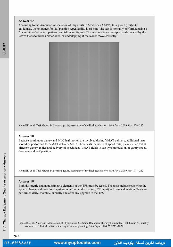
344
QUAL
ITY
11
.1 T
hera
py
Eq
uip
men
t Q
ualit
y A
ssur
ance
• A
nsw
ers
Answer 17According to the American Association of Physicists in Medicine (AAPM) task group (TG)-142 guidelines, the tolerance for leaf position repeatability is ±1 mm. The test is normally performed using a “picket fence”–like test pattern (see following figure). This test irradiates multiple bands created by the leaves that should be neither over- or underlapping if the leaves move correctly.
Klein EE, et al. Task Group 142 report: quality assurance of medical accelerators. Med Phys. 2009;36:4197–4212.
Answer 19Both dosimetric and nondosimetric elements of the TPS must be tested. The tests include reviewing the system change and error logs, system input/output devices (eg, CT input) and dose calculation. Tests are performed daily, monthly, annually and after any upgrade to the TPS.
Fraass B, et al. American Association of Physicists in Medicine Radiation Therapy Committee Task Group 53: quality assurance of clinical radiation therapy treatment planning. Med Phys. 1994;25:1773–1829.
Answer 18Because continuous gantry and MLC leaf motion are involved during VMAT delivery, additional tests should be performed for VMAT delivery MLC. Those tests include leaf speed tests, picket-fence test at different gantry angles and delivery of specialized VMAT fields to test synchronization of gantry speed, dose rate and leaf position.
Klein EE, et al. Task Group 142 report: quality assurance of medical accelerators. Med Phys. 2009;36:4197–4212.

345
QUAL
ITY
11
.1 T
hera
py
Eq
uip
men
t Q
ualit
y A
ssur
ance
• Q
uest
ions
Question 23What are periodic quality assurance (QA) procedures on dose calculation for treatment planning systems (TPS)?
Question 22What are the quality assurance (QA) procedures on plan evaluation (dose-volume histogram) in treatment planning systems (TPS)?
Question 21What are the periodic quality assurance (QA) procedures on CT images in treatment planning systems (TPS)?
Question 20What is an end-to-end test?
346
QUAL
ITY
11
.1 T
hera
py
Eq
uip
men
t Q
ualit
y A
ssur
ance
• A
nsw
ers
Answer 21Because the majority of radiation therapy dose calculation is CT-based calculation, it is important to perform periodic QA on CT images. Those tests include CT scan transfer, CT geometry and CT number (related to the electron density of the tissue) check.
Fraass B, et al. American Association of Physicists in Medicine Radiation Therapy Committee Task Group 53: quality assurance of clinical radiation therapy treatment planning. Med Phys. 1994;25:1773–1829.
Answer 23For treatment planning systems the most critical issue is the accuracy and consistency of dose and monitor units (MU) calculation. The following tests are recommended by Technical Report Series (TRS) 430: (a) calculated dose per beam; (b) beam weighting; (c) summed dose distribution; (d) plan normalization; and (e) MU calculations.
IAEA TRS 430. Commissioning and quality assurance of computerized planning systems for radiation treatment of cancer. IAEA. 2004.
Answer 22These tests include plan normalization, relative and absolute dose, volume determination, histogram dose bin size, calculation of grid size and points distributions, consistency in structure and dose statistics.
IAEA TRS 430. Commissioning and quality assurance of computerized planning systems for radiation treatment of cancer. IAEA. 2004.
Answer 20An end-to-end test checks the entire radiation therapy system. It starts with the CT of a specialized phantom, on which an isocenter is marked. The CT is sent to the treatment planning systems (TPS) and planned. The plan is then sent to the linear accelerator (linac). The phantom is placed according to the isocenter marks, and port films taken to ensure the fields planned match the shapes within the phantom. In the case of Radiation Therapy Oncology Group (RTOG) credentialing, the plan is delivered to the phantom which contains film and thermoluminescence dosimeters (TLDs). The dose measured is then compared to the plan to confirm accuracy of delivering the planned dose.

347
QUAL
ITY
11
.2 P
atie
nt S
afet
y •
Que
stio
ns
Question 25What is required for commissioning for a medical linear accelerator?
Question 1 11.2 PATIENT SAFETYWhat is the new patient safety initiative launched jointly by the American Society of Radiation Oncology (ASTRO) and the American Association of Physicists in Medicine (AAPM)?
Question 2Where can you find guidelines to follow in making decisions regarding patient safety issues?
Question 24What is acceptance testing for a medical linear accelerator?

348
QUAL
ITY
11
.2 P
atie
nt S
afet
y •
Ans
wer
s
Answer 25The process of commissioning a linear accelerator involves a comprehensive and accurate measurement of all dosimetric parameters to completely describe the radiation beams. This information is then used to model the accelerator in the treatment planning system. Annually, measurements are taken to confirm the radiation beams still conform to the original commissioning data. If it does not conform, the treatment planning systems (TPS) beam model will have to be updated.
Das IJ, et al. Accelerator beam data commissioning equipment and procedure: report of the TG-106 of the Therapy Physics Committee of the AAPM. Med Phys. 2008;35:4186–4215.
Answer 2Task group (TG) reports from the American Association of Physicists in Medicine (AAPM), white papers from ASTRO, the American College of Radiology (ACR)/ASTRO accreditation and practice standards, and government regulations (eg, 10 Code of Federal Regulations (CFR) part 20).
Answer 1The Radiation Oncology Incident Learning SystemTM (RO-ILS) was launched in 2014. RO-ILS documents, analyzes and tracks patient safety-related incidents submitted by participating Radiation Oncology centers.
Answer 24Performed by a qualified medical physicist, the acceptance testing ensures the machine meets the specifications of the manufacture and of the purchase agreement. The tests include a number of safety, mechanical, and dosimetric checks. The safety checks (door interlocks, emergency stops, and survey of exposure levels in the treatment control area), should be done before other tests to ensure a safe environment for the testers.
Kutcher GJ, et al. Comprehensive QA for radiation oncology: report of AAPM Radiation Therapy Committee Task Group 40. Med Phys. 1994;21:581–618.

349
QUAL
ITY
11
.2 P
atie
nt S
afet
y •
Que
stio
ns
Question 4Who regulates naturally occurring radioactive materials and X-ray machines?
Question 5What safety measures must be included in the practice of radiation oncology?
Question 6Given the routine use of cone-beam CT (CBCT)-based image verification, what are the current designs to avoid mechanical injury by the machine?
Question 3What agency regulates reactor-produced materials?

350
QUAL
ITY
11
.2 P
atie
nt S
afet
y •
Ans
wer
s
Answer 4Individual states regulate these forms of radiation.
Answer 6A mechanical system, a protection ring attached to the gantry with springs, is used on Elekta linear accelerators (linacs), and a laser detection system is installed on current Varian machines (laser guard). In addition, the kV and MV image panels have interlocks, which will stop the gantry motion when the force applied on the panel exceeds the preset limits. Based on the pre-CBCT couch positions, the Varian control system can move the couch to a “safe zone” before the image acquisition to avoid potential collisions. The couch will be restored to its initial position after the CBCT imaging. Despite these safety designs, it is recommended that radiation therapists perform a dry run to check the possible mechanical injury to the patient from the machine.
Answer 5a. A treatment management system for prescription, treatment parameters setup and delivery, and daily
dose recording and summationb. A physics program for calibrating equipment that ensures accurate dose delivery to the
patientc. A system for independent verification of treatment parameters (external beam) by another
qualified person or method before the first treatmentd. A system for the radiation oncologist and medical physicist to independently check all rel-
evant brachytherapy practice parameters to be used prior to each proceduree. A program to prevent mechanical injury by the machine or accessory equipmentf. Visual and audio contact with the patient while under treatmentg. A policy requiring two forms of patient identification as well as verification of treatment
parameters prior to each treatment
ACR-ASTRO Practice Parameter for Radiation Oncology Revised 2014, available at http://www.acr.org/guidelines
Answer 3The Nuclear Regulatory Commission (NRC) regulates the reactor-produced materials such as cobalt-60 (Co-60). States can choose to adopt the NRC regulations and become agreement states.

351
QUAL
ITY
11
.2 P
atie
nt S
afet
y •
Que
stio
ns
Question 8What quality assurance (QA) checks should be performed in radiation oncology? Among the QA checks, which individual check is the most effective for detecting potential errors?
Question 9Among the members of the treatment team, who can declare a “time-out”?
Question 10Is it necessary to implement the checklist procedure in the practice of radiation oncology?
Question 7Which two forms of patient identification are commonly used in radiation oncology?

352
QUAL
ITY
11
.2 P
atie
nt S
afet
y •
Ans
wer
s
Answer 8QA checks that should be performed include physician plan review, physics plan review, therapist chart review, pretreatment intensity-modulated radiation therapy (IMRT) QA, Chart rounds, timeout by therapist, source-to-surface distance (SSD) check, port films, online CT, in vivo dosimetry, and physics weekly checks. Physics plan review is more sensitive than other individual checks.
Ford EC, Terezakis S, Souranis A, et al. Quality control quantification (QCQ): a tool to measure the value of quality control checks in radiation oncology. Int J Radiat Oncol Biol Phys. 2012;84:e263–e269.
Answer 9Each member of the treatment team (including therapists, physicists, physicians, etc.) should have a right to declare a time-out if he or she has a concern or question regarding the plan and treatment during the course of the treatment.
Hendee WR. Herman MG Improving patient safety in radiation oncology. Prac Radiat Oncol. 2011:16–21.
Answer 10Yes. Studies have shown that the use of medical checklist reduces the likelihood of errors in medical practice.
Gawande A. The Checklist Manifesto: How to Get Things Right. New York, NY: Metropolitan Books; 2009.
Answer 7A common combination of patient identification is a patient’s full name and date of birth. An identifica-tion wristband or face photo can also be used.

353
QUAL
ITY
11
.2 P
atie
nt S
afet
y •
Que
stio
ns
Question 12What are the action levels for patient specific intensity-modulated radiation therapy (IMRT) quality assurance (QA)?
Question 13What are the recommendations for the treatment of patients with implanted cardiac pacemaker?
Question 14A patient has been diagnosed with cervical carcinoma and has decided to start radiation therapy. What will happen with her pregnancy?
Question 15A pregnant patient needs to undergo whole brain radiation therapy. What are the recommendations when you simulate and port the patient?
Question 11Why is patient specific intensity-modulated radiation therapy (IMRT) quality assurance (QA) necessary?
354
QUAL
ITY
11
.2 P
atie
nt S
afet
y •
Ans
wer
s
Answer 12The action levels can vary based upon the type of treatment, disease site, measurement device, delivery method, etc. Typically, the action level for the absolute point dose difference between the planned and measured dose is ± 5%. Comparing the measured and planned dose distribution is typically achieved with a gamma index, where a >90% of passing rate using 3%/3 mm criteria is required. For stereotactic body radiation therapy (SBRT), the action levels can be more stringent than conventional IMRT treatment.
Low DA, et al. A technique for the quantitative evaluation of dose distributions. Med Phys. 1998;35:879–887.
Answer 13The American Association of Physicists in Medicine (AAPM) task group (TG)-34 recommends limiting accumulated dose to the pacemaker to 2 Gy. Individual manufacturers may, however, have lower limits. It is also a good practice to avoid using photon beams with energy above 10 MV, to remove neutrons, which may directly damage the electronics of the pacemaker. There is an active task group (TG)-203 formed by AAPM to update the information regarding this issue.
Marback JR, et al. Management of radiation oncology patients with implanted cardiac pacemakers: report of AAPM Task Group No. 34. Med Phys. 1994; 21:85–90.
Answer 14According to the Nuclear Regulatory Commission (NRC) 10 Code of Federal Regulations (CFR) Part 20.1208, the dose equivalent to the embryo/fetus should not exceed 5 mSv during the entire pregnancy. Doses below 0.1 Gy should be safe, with doses up to 0.5 Gy not necessarily fatal, depending on the stage of the pregnancy, but would result in fetal damage. Treatment of cervical cancer is not compatible with preservation of the fetus.
Kal HB, Struikmans H. Radiation therapy during pregnancy: fact and fiction. Lancet Oncol. 2005;6:328–333
Answer 15Following the As Low as Reasonably Achievable (ALARA) principle, one should conduct a CT scan with large slice thickness (eg, >5 mm), short scan range along the superior-inferior direction, and low kVp and/or mAs. When doing portal imaging, a single exposure portal image is recommended.
Answer 11Based upon the American College of Radiology (ACR) guidelines, the accuracy of dose delivery must be documented for each course of treatment by irradiating a phantom that contains either calibrated film to sample the dose distribution or an equivalent measurement system (such as an ion chamber or diode array) to verify that the dose delivered is the dose planned.
ACR-ASTRO practice parameter for intensity modulated radiation therapy (IMRT) Amended 2014 (Resolution 39).

355
QUAL
ITY
11
.2 P
atie
nt S
afet
y •
Que
stio
ns
Question 16According to the Nuclear Regulatory Commission (NRC), who should be included in the radiation safety committee to oversee the use of byproduct material at a medical institution?
Question 17For stereotactic body radiation therapy (SBRT) treatments, should a radiation oncologist be present at the start of each treatment, prior to irradiation?
Question 18According to the Nuclear Regulatory Commission (NRC), what are the components of a written directive?
Question 19What is the dose limit used for the Nuclear Regulatory Commission (NRC) 10 Code of Federal Regulations (CFR) part 35 (report and notification of a medical event)?
Question 20If a medical event is discovered, how soon should a licensee notify the Nuclear Regulatory Commission (NRC) by phone?
356
QUAL
ITY
11
.2 P
atie
nt S
afet
y •
Ans
wer
s
Answer 16The committee should include the authorized user, the radiation safety officer (RSO), a nurse, and a representative of management who is neither an authorized user nor an RSO.
Answer 17Yes. Before each treatment, the radiation oncologist must be present to verify the integrity of the patient setup and patient positioning using image guidance.
Solberg TD, Balter JM, Benedict SH, et al. Quality and safety considerations in stereotactic radiosurgery and stereotac-tic body radiation therapy. Prac Raidat Oncol. 2011 (white paper).
Answer 18A written directive is required for source-based procedures (brachytherapy, gamma knife and other source-based teletherapy). Depending on the type of application (high dose rate [HDR], low dose rate [LDR], permanent or temporary), the directive must contain: the dosage (and fractionation if applicable), route of delivery, radionuclide, number of sources and total source strength, treatment site, and the patient’s name. This must be signed by the authorized user physician.
Answer 19The dose limit is 0.05 Sv (5 rem) effective dose equivalent, 0.5 Sv (50 rem) to an organ or tissue, or 0.5 Sv (50 rem) shallow dose equivalent to the skin.
Answer 20According to NRC 10 Code of Federal Regulations (CFR) 30.3045, a licensee shall notify by phone the NRC operation center no later than the next calendar day after discovery of the event. The licensee shall submit a written report to the appropriate NRC regional office within 15 calendar days after the discovery of the event.

12RADIATION SAFETY AND REGULATIONS
MIKE STRONGOSKY AND HENRY BLAIR
12.1 RULES AND REGULATIONS 359
12.2 SHIELDING 375

359
RADI
ATIO
N SA
FETY
AND
REG
ULAT
IONS
12
.1 R
ules
and
Reg
ulat
ions
• Q
uest
ions
Question 4What does ALARA stand for?
Question 3What is the frequency for survey meter calibration?
Question 2What is the survey limit requirement for a patient’s release who has received a radioactive source or radiopharmaceutical?
Question 1 12.1 RULES AND REGULATIONSWhat is the frequency for inventory and survey for a radioactive material storage area, for example, Cs-137?
Turn page to see the answers.

360
12
.1 R
ules
and
Reg
ulat
ions
• A
nsw
ers
Answer 4As Low As Reasonably Achievable. This is the basis of radiation protection planning and accounts for the cost and effort to reduce the risk of radiation to zero.
Answer 3Annually, before the initial use and after any repair.
Answer 2The Nuclear Regulatory Commission (NRC) guidelines are based on keeping the radiation level to a member of the public the patient may interact with below 500 mrem. Therefore, the survey limit is different depending on the source used, a table is provided by the NRC. For I-131 it is <7 mrem/hr and for I-125 it is 1 mrem/hr, both measured at 1 m from the patient surface.
Answer 1Quarterly, according to Nuclear Regulatory Commission (NRC) rules.
RADI
ATIO
N SA
FETY
AND
REG
ULAT
IONS

361
12
.1 R
ules
and
Reg
ulat
ions
• Q
uest
ions
Question 7What is the lifetime limit for a radiation worker?
Question 6As a radiation worker, if you separately undergo radiation therapy, does this affect your annual dose limit?
Question 5What is the negligible individual risk level (NIRL)?
Question 8What is equivalent dose?
RADI
ATIO
N SA
FETY
AND
REG
ULAT
IONS

362
12
.1 R
ules
and
Reg
ulat
ions
• A
nsw
ers
Answer 8Equivalent dose takes into account the different biological effects of different types of radiation, such as photon, proton, thermal neutrons (<10 MeV), neutrons, and heavy particles. Equivalent dose is the dose in Gy (J/kg) multiplied by the radiation weighting factor (W
R) of the radiation. Its unit is the Sievert (Sv). The
old unit was rem, 100 rem = 1 Sv.
Answer 7The National Council on Radiation Protection and Measurements (NCRP) limit is 10 mSv multiplied by age in years.
Answer 6The 50 mSv per year is an occupational dose limit; it does not include radiation from background, medical exposure as a patient, or dose as a member of the general public.
Answer 5The National Council on Radiation Protection and Measurements (NCRP) definition of NIRL is “the level of average annual excess risk of fatal health effects attributable to radiation below which efforts to reduce radiation exposure to the individual is unwarranted.” The current value is 0.01 mSv.
RADI
ATIO
N SA
FETY
AND
REG
ULAT
IONS

363
12
.1 R
ules
and
Reg
ulat
ions
• Q
uest
ions
Question 9What are the International Commission on Radiological Protection (ICRP) recommended values for radia-tion weighting factors W
R?
Question 11What are the National Council on Radiation Protection and Measurements (NCRP) values for tissue weighting factors w
T?
Question 10What is effective dose equivalent (EDE)?
Question 12What is the whole body effective dose equivalent (EDE) limit for a member of the general public?
RADI
ATIO
N SA
FETY
AND
REG
ULAT
IONS

364
12
.1 R
ules
and
Reg
ulat
ions
• A
nsw
ers
Answer 121 mSv/y (100 mrem/y), this is determined based on risk compared to other every day hazards.
Answer 11
Tissue Tissue Weighting Factor
Gonads 0.2
Bone marrow, colon, lung, stomach 0.12
Bladder, breast, esophagus, liver, thyroid 0.05
Bone surface, skin 0.01
Remaining tissues (adrenals, brain, small and large intestine, kidney, muscle, pancreas, spleen, thymus, and uterus)
0.05
The sum of the tissue weighting factors is 1, so the effective dose equals the absorbed dose when the body is uniformly irradiated.
Answer 10Just as equivalent dose takes into account the damage of different types of radiation, effective dose takes into account the sensitivity of different tissues, effective dose equals absorbed dose multiplied by the tissue weighting factors. EDE is then the combination of absorbed dose, multiplied by the radiation and tissue weighting factors.
Answer 9
Types of Radiation Radiation Weighting Factor
X-ray, Gamma ray, electrons, and beta particles 1
Protons 2
Neutrons A range from 5 to 20 depending on energy
RADI
ATIO
N SA
FETY
AND
REG
ULAT
IONS
NCRP Report 116 Limitation of Exposure to Ionizing Radiation, 1993

365
12
.1 R
ules
and
Reg
ulat
ions
• Q
uest
ions
Question 16What types of radiation badges are available?
Question 15What is the dose limit for radiation workers to the eyes and extremities?
Question 14What is the effective dose equivalent (EDE) limit for a pregnant occupational worker?
Question 13What is the whole body effective dose equivalent (EDE) limit for an occupational worker?
RADI
ATIO
N SA
FETY
AND
REG
ULAT
IONS

366
12
.1 R
ules
and
Reg
ulat
ions
• A
nsw
ers
Answer 16X-ray film, thermoluminescent dosimeter (TLD) badges, and optically stimulated luminescent dosimeter (OSLD). These are available as body and ring badges.
Answer 15The extremities are limited to 500 mSv/y and the lenses of the eye to 150 mSv/y.
Answer 145 mSv/term (0.5 mSv/month).
Answer 1350 mSv/y (5,000 mrem/y).
RADI
ATIO
N SA
FETY
AND
REG
ULAT
IONS

367
12
.1 R
ules
and
Reg
ulat
ions
• Q
uest
ions
Question 20What is the purpose of the Conference of Radiation Control Program Directors (CRCPD)?
Question 19What are the Nuclear Regulatory Commission (NRC) requirements for determining if hospital staff needs radiation monitoring badges?
Question 18What percentage of medical radiation exposure do CT studies account for?
Question 17What is the average yearly exposure (per person) in the United States from background radiation?
RADI
ATIO
N SA
FETY
AND
REG
ULAT
IONS
368
12
.1 R
ules
and
Reg
ulat
ions
• A
nsw
ers
Answer 20One of the main functions of the CRCPD is to produce suggested state regulations for control of radiation. These are referred to by individual states as guidelines in creating their own regulations governing radiation therapy.
Answer 19The NRC requires monitoring if there is a likelihood of the individual receiving more than 10% of the annual occupational limit and/or having access to areas where the radiation exposure rate could exceed 1 mSv (100 mrem) per hour.
Answer 18Approximately 50%.
Answer 173.1 mSv, depending on geographic location. The majority of this (2.3 mSv) is from Radon.
RADI
ATIO
N SA
FETY
AND
REG
ULAT
IONS

369
12
.1 R
ules
and
Reg
ulat
ions
• Q
uest
ions
Question 24For each piece of therapy equipment, what information is typically required to be kept?
Question 23What are the requirements (limits) for radioactive material transportation labels: White I, Yellow II, and Yellow III?
Question 22What does the transport index (TI) on a package of radioactive material indicate?
Question 21Who regulates the transport of radioactive materials?
RADI
ATIO
N SA
FETY
AND
REG
ULAT
IONS

370
12
.1 R
ules
and
Reg
ulat
ions
• A
nsw
ers
Answer 24(a) Report of acceptance testing.(b) Records of all surveys, calibrations and periodic QA checks, and names of the people who
performed them.(c) Records of maintenance and/or modifications performed, as well as the names of people who
performed such services.(d) Name and signature of the qualified medical physicist or authorized individual authorizing the
return of the therapy equipment to clinical use after any service or intervention that affects patient treatment.
Answer 23
Label Surface Radiation Radiation at 1 m
White I <0.5 mrem/h Not applicable
Yellow II <50 mrem/h AND <1 mrem/h
Yellow III Exceeds 50 mrem/h OR Exceeds 1 mrem/h
Answer 22The highest dose rate at 1 m from the surface. This partially determines the type of label placed on the package, either White I for TI of 0, Yellow II for TI less than 1, or Yellow III otherwise.
Answer 21Department of Transportation.
RADI
ATIO
N SA
FETY
AND
REG
ULAT
IONS

371
12
.1 R
ules
and
Reg
ulat
ions
• Q
uest
ions
Question 28A medical event (misadministration) for external beam therapy is defined by the calculated total adminis-tered dose differing from the total prescribed dose by more than what percent?
Question 27A medical event (misadministration) for external beam therapy is defined by the calculated weekly admin-istered dose differing from the weekly prescribed dose by more than what percent?
Question 26What is the typical process for the radiation oncologist checking port films?
Question 25What is the American College of Radiology (ACR) recommendation regarding an independent check (second check) of initial dose calculations?
RADI
ATIO
N SA
FETY
AND
REG
ULAT
IONS

372
12
.1 R
ules
and
Reg
ulat
ions
• A
nsw
ers
Answer 2820%, unless the treatment has three or fewer fractions, in which case the limit is 10%.
Answer 2730%.
Answer 26Initial port films shall be checked by the radiation oncologist prior to the second treatment and the port films shall be rechecked at least every 10 treatments.
Answer 25The check shall be conducted before the third fraction or before 20% of the total dose when the treatment schedule provides less than 10 fractions. The independent check includes utilizing another individual or method approved and documented by the medical physicist to verify dose calculations.
RADI
ATIO
N SA
FETY
AND
REG
ULAT
IONS

373
12
.1 R
ules
and
Reg
ulat
ions
• Q
uest
ions
Question 32After initially notifying the regulating body of a medical event (misadministration), how long do you have to notify the referring physician?
Question 31After it has been ascertained that a medical event has occurred, what are the time requirements (verbal and written) for reporting it to the regulating body?
Question 30What is the definition of a medical event for radioactive material?
Question 29Besides exceeding the permissible differences between administered and calculated doses; what are the other three ways to define a medical event (misadministration) for external beam therapy?
RADI
ATIO
N SA
FETY
AND
REG
ULAT
IONS

374
12
.1 R
ules
and
Reg
ulat
ions
• A
nsw
ers
Answer 30Any of the following is a medical event: (a) if one or more sealed sources are leaking; (b) administration of the wrong radioactive drug/material; (c) administration to the wrong individual; (d) administration by the wrong mode of treatment; (e) the delivered dose deviated greater than 20% of the prescription dose.
Answer 29Wrong patient, wrong treatment, or wrong treatment site.
Answer 32No later than 24 hours.
Answer 31By telephone no later than the next calendar day (24 hours) and a written report within 15 days.
RADI
ATIO
N SA
FETY
AND
REG
ULAT
IONS

375
12
.2 S
hiel
din
g •
Que
stio
ns
Question 34What are the differences between stochastic and nonstochastic (deterministic) effects?
Question 33How long must a record of a medical event (misadministration) be kept?
Question 2What is the definition of use factor (U)?
Question 1 12.2 SHIELDINGIn the equation for primary barrier shielding, B
p = P(d
pri)2/WUT where B
p is the thickness of shielding
required, identify dpri
, P, W, U, T.
RADI
ATIO
N SA
FETY
AND
REG
ULAT
IONS
376
Answer 34Stochastic effects are nondeterministic or random in nature. The severity of damage is independent of the dose, but the probability of a biological effect increases with the dose. An example of a stochastic effect is cancer. There is usually a threshold dose for nonstochastic effects, the severity of which varies with the dose. Examples of nonstochastic effects would be erythema and cataract formation.
Answer 33Three years.
Answer 2Use factor is the fraction of the time per week that the primary beam falls on the barrier. Typical use factors are floor 0.31, walls 0.2, and ceiling 0.26. In the case of secondary barriers, U = 1 is assumed due to scattered radiation and head leakage uniformly distributed around the vault.
NCRP Report No 151 Structural Shielding Design and Evaluation For Megavoltage X- and Gamma-Ray Radiation therapy Facilities, 2005.
Answer 1P is dose limit per week permitted outside the barrier for protection, d
pri is distance in meters from
the primary radiation source to point protected, W = workload (expressed in Gy/wk), U = use factor, T = occupancy factor.
12
.2 S
hiel
din
g •
Ans
wer
sRA
DIAT
ION
SAFE
TY A
ND R
EGUL
ATIO
NS

377
Question 3What is the definition of occupancy factor (T)? Give some examples of common occupancy factors.
Question 4For the dose limit per week permitted outside the barrier for protection (P) in the shielding equation, what is the maximum permissible radiation measured in mR for controlled and noncontrolled areas?
Question 6What is the use factor, U, for secondary barriers?
Question 5In the equation for the secondary barriers to shield against scattered radiation B
s = Pd2
sca d2
sec400/αWTF
(F = beam size at the patient), what does “α” represent? What is the unit for the distance of dsca
and dsec
?
RADI
ATIO
N SA
FETY
AND
REG
ULAT
IONS
12
.2 S
hiel
din
g •
Que
stio
ns
378
Answer 3The fraction of time a particular area will be occupied. Examples: Full occupancy (T = 1) offices, laboratories, occupied buildings or living quarters, clinical work stations. Partial occupancy (T = 1/5) rest rooms, corridors. Occasional occupancy (T = 1/20) waiting rooms, stairways, closets.
NCRP Report No 151 Structural Shielding Design and Evaluation For Megavoltage X- and Gamma-Ray Radiation therapy Facilities, 2005.
Answer 4A controlled area is for radiation workers so its dose levels are consistent with the dose limits of radiation workers, namely 1 mSv/wk and 50 mSv/y (100 mrem/wk and 5,000 mrem/y). Noncontrolled areas are for the public, and the limits are 0.02 mSv/wk and 1 mSv/y (2 mrem/wk or 100 mrem/y).
Answer 5Scattered radiation is radiation that scatters from the primary treatment beam. It therefore has a lower energy than the primary beam. “α” is the fractional scatter at 1 m from the scatterer (eg, wall). It depends on angle and field size. At 90° a typical α is 10−3 to 10−4. d
sca is the distance from the source to the scatter;
dsec
is the distance from the scatter to the area of interest both measured in meters.
Answer 6U is 1 because the secondary barriers are always exposed to the scattered radiation and head leakage when the beam is on.
12
.2 S
hiel
din
g •
Ans
wer
sRA
DIAT
ION
SAFE
TY A
ND R
EGUL
ATIO
NS

379
Question 10What materials are commonly added to vault doors to help reduce dose from neutrons?
Question 9What is a TVL?
Question 7Neutrons can be generated above what energy?
Question 8What is the advantage of using a maze for a radiation therapy vault?
RADI
ATIO
N SA
FETY
AND
REG
ULAT
IONS
12
.2 S
hiel
din
g •
Que
stio
ns

380
Answer 8The use of a maze can ease the design of the door. Without a maze, the door must be thick enough to provide shielding equivalent to the wall surrounding the door. For mega-voltage vaults, the door would be very thick and heavy and therefore slow to open and close.
Answer 7Photon beams of 10 MV and above are capable of producing neutrons by photonuclear reactions, where a high energy photon interacts directly with a nucleus placing it into an excited state, which then decays via neutron emission.
Answer 9TVL stands for tenth value layer for a specific material and is used to describe thicknesses required for shielding. One tenth-value layer is defined as the amount of shielding material required to reduce the radiation intensity to one tenth of the unshielded value. One TVL equals 3.3 half-value layers.
Answer 10Boron and polyethylene, as they moderate the fast and intermediate energy neutrons.
12
.2 S
hiel
din
g •
Ans
wer
sRA
DIAT
ION
SAFE
TY A
ND R
EGUL
ATIO
NS

381
Question 12For a PET CT scanner, what component (PET or CT) requires more consideration for shielding?
Question 11For what energy should a high-dose rate brachytherapy room using an Ir-192 source be shielded?
Question 13Is more shielding required in the patient holding area or the actual scanning room for PET CT?
Question 14What is the dose limit for a radiation area?
RADI
ATIO
N SA
FETY
AND
REG
ULAT
IONS
12
.2 S
hiel
din
g •
Que
stio
ns

382
Answer 12Fluorine-18 (F-18) is the most common isotope for PET. It has a half-life of 110 minutes. It primarily decays by positron emission, eventually resulting in a photon of energy 511 keV. The X-ray energy for a CT scanner is typically below 140 kVp, so the PET component is the main consideration for shielding.
Answer 11Although the average energy for Ir-192 is 380 keV, Ir-192 has a relatively wide energy spectrum that can reach 1.06 MeV.
Answer 13The holding area requires more shielding because the Fluorine-18 (F-18) is injected into the patient one hour before acquiring the PET/CT. The decay of F-18 occurs regardless of whether or not the PET/CT images are acquired. Since the patient spends considerably more time in the holding area, the holding area requires more shielding than the scanning room.
Answer 14The dose limit for a radiation area is 0.05 mSv/hr (5 mrem/hr) at 30 cm from the source. An example of a radiation area would be a CT simulator. A sign must be posted to alert individuals.
12
.2 S
hiel
din
g •
Ans
wer
sRA
DIAT
ION
SAFE
TY A
ND R
EGUL
ATIO
NS
383
Question 16What signage is required outside of a high-dose rate brachytherapy afterloader room?
Question 15What is the dose limit for a high radiation area?
RADI
ATIO
N SA
FETY
AND
REG
ULAT
IONS
12
.2 S
hiel
din
g •
Que
stio
ns

384
Answer 15The dose limit for a high radiation area is 1 mSv/hr (100 mrem/hr) at 30 cm from the source or any surface the radiation penetrates. An example would be a linear accelerator or high dose rate (HDR) vault, and a sign must be posted.
Answer 16High Radiation Area and Radioactive Material sign.
12
.2 S
hiel
din
g •
Ans
wer
sRA
DIAT
ION
SAFE
TY A
ND R
EGUL
ATIO
NS

13DIAGNOSTIC IMAGING
KEVIN WUNDERLE, NICHOLAS SHKUMAT, AND FRANK DONG
13.1 RADIOGRAPHY AND FLUOROSCOPY 387
13.2 MRI 393
13.3 MAMMOGRAPHY 399
13.4 NUCLEAR IMAGING 403
13.5 CT 409
13.6 ULTRASOUND 417
387
DIAG
NOST
IC IM
AGIN
G
Question 4Assuming no other changes, as the image receptor is moved farther away from the patient, what happens to the anatomy in the image?
Question 3For all diagnostic X-ray imaging, where does the depth of maximum dose (D
max) reside?
Question 2What is the general range of kVps used for diagnostic imaging?
Question 1 13.1 RADIOGRAPHY AND FLUOROSCOPYWhy is there a significant difference in image contrast between a general radiograph and a portal image (or film) of the same patient and same anatomy?
Turn page to see the answers.
13
.1 R
adio
gra
phy
and
Flu
oro
sco
py
• Q
uest
ions

388
DIAG
NOST
IC IM
AGIN
G
Answer 4As the image receptor is moved away from the patient with no other changes in geometry, the anatomy in the image will be magnified. The magnification factor will be equal to the source to image distance/source to object distance (SID/SOD).
Answer 3D
max resides at the skin surface for diagnostic energy X-ray beams; there is essentially no buildup depth
for kilovoltage X-rays.
Answer 2The typical operational range of kVps for diagnostic imaging is between 60 and 120 kVp. The kVp used for a given exam will depend on the anatomy to be imaged and the desired image quality.
Answer 1The greater contrast in the general radiographic image results from lower energy photons (kilovoltage) having a larger fraction of photoelectric interactions. This is especially apparent when bone is imaged. The photoelectric effect is proportional to (Z/E)3; therefore, high-Z and low-E result in very large absorption, hence increased contrast. In comparison, portal images in radiation therapy use the megavoltage (MV) energy treatment beam. For MV energy photons, Compton scattering is the dominant interaction with tissue. Compton interactions are dependent on electron density, which varies minimally between tissue types.
13
.1 R
adio
gra
phy
and
Flu
oro
sco
py
• A
nsw
ers

389
DIAG
NOST
IC IM
AGIN
G
Question 7What are the patient dose limits for radiographic and/or fluoroscopic procedures?
Question 6For X-ray-based angiography, what are the two primary factors contributing to blurring of the vessels in the image?
Question 5In an automatic exposure control (AEC) or automatic brightness control (ABC) image acquisition, moving the patient as close to the image receptor as possible will have what effect on patient skin entrance dose?
Question 8For all modern fluoroscopic units (manufactured after 2006), the cumulative air kinetic energy released per unit mass (kerma) is required to be displayed. Is the cumulative air kerma equivalent to the patient skin dose?
13
.1 R
adio
gra
phy
and
Flu
oro
sco
py
• Q
uest
ions

390
DIAG
NOST
IC IM
AGIN
G
Answer 8The displayed air kerma on fluoroscopes is an air kerma calculated to a reference plane. The reported air kerma is the sum of all radiation output, in all projections. Therefore, this value does not directly relate to a skin dose since it does not account for the geometric dose distribution. Additionally, the reported air kerma can substantially deviate from the skin dose because it does not account for the accuracy of the ion chamber (which may deviate by ±35%), attenuation factors of the table and pad (which can exceed 30%), tissue back scatter factors, and f-factors based on photon energy.
Answer 7There are no regulatory limits for patient radiation dose for radiographic or fluoroscopic procedures. However, the Joint Commission does define a sentinel event for fluoroscopic procedures resulting in a cumulative skin dose of 15 Gy, or more, to a single field.
Answer 6The two primary factors contributing to blurring of vessels in an image are the focal spot size and the location of the anatomy in relation to the image receptor (greater distance results in greater geometric blur).
Answer 5Reducing the distance between the patient and the image receptor for an AEC or ABC image acquisition will reduce the patient skin entrance dose. Dose reduction will be proportional to (SSD
initial/SSD
final)2
(inverse square law), where SSD is source to skin distance.
13
.1 R
adio
gra
phy
and
Flu
oro
sco
py
• A
nsw
ers

391
DIAG
NOST
IC IM
AGIN
G
Question 9For imaging performed with image intensifier-based fluoroscopes, where in the image field of view should the anatomy of interest be placed?
Question 11For fluoroscopic imaging, when the field of view (FOV) is changed by increasing the magnification, how is the air kinetic energy released per unit mass (kerma) rate at a fixed location affected?
Question 10What is the conversion sequence of the image signal, starting with the X-rays exiting the patient and end-ing with the output phosphor, in an image intensifier?
Question 12State-of-the-art fluoroscopic systems use dynamic copper (Cu) filtration. What is the purpose of these filters and how do they affect image quality?
13
.1 R
adio
gra
phy
and
Flu
oro
sco
py
• Q
uest
ions

392
DIAG
NOST
IC IM
AGIN
G
Answer 12The Cu filters are used to harden the X-ray beam, thereby reducing the skin entrance dose. However, as an X-ray beam is hardened there is a subsequent loss of contrast in the image.
Answer 11When the FOV is decreased (by increased magnification ) the air kerma rate will increase. For image intensifier-based systems, the increase will be proportional to the square of the ratio of beam areas (A
2/A
1)2. For digital image receptors, generally the air kerma rate increases; however, the increase is not
necessarily related to the beam area.
Answer 10The X-rays leave the patient and pass through the grid, where some are absorbed. They then reach the input phosphor, where the X-rays are converted to light. Directly behind the input phosphor, the light photons are converted to electrons by the photocathode. The electrons are accelerated across the evacuated tube and strike the output phosphor, converting the electrons back to light.
Answer 9All image intensifiers have some geometric distortion that typically increases near the periphery of the image; therefore, the anatomy of interest should be placed in the center of the image.
13
.1 R
adio
gra
phy
and
Flu
oro
sco
py
• A
nsw
ers
393
DIAG
NOST
IC IM
AGIN
G1
3.2
MR
I • Q
uest
ions
Question 15Which image receptor has the highest potential spatial resolution: an image intensifier, a digital flat panel detector, or traditional film?
Question 14If the air-kerma-area-product rate (AKAP; kerma: kinetic energy released per unit mass) is measured free-in-air 50 cm from an X-ray source and then again at 100 cm from the same X-ray source, how does this measurement change?
Question 13Assuming that other factors do not change; does reducing the X-ray field size by collimation reduce the air kerma (kinetic energy released per unit mass) rate, the air-kerma-area-product rate (AKAP) or both?
Question 1 13.2 MRIIn T2-weighted MRI of the prostate, a tumor is visibly darker than the surrounding normal tissue. Why?

394
DIAG
NOST
IC IM
AGIN
G1
3.2
MR
I • A
nsw
ers
Answer 15The spatial resolution capabilities for film are much greater than for any other current image receptor. The primary benefit of using a digital detector is the ability it offers the operator to adjust the window and level, providing dynamic contrast adjustment.
Answer 14AKAP is not impacted by the plane of measurement; therefore, the values will be identical. Even though the air kerma decreases by the inverse square law with distance from a radiation source, the area of the beam increases by the same proportion.
Answer 13The AKAP rate will be reduced, but the air kerma rate will remain unchanged. Air kerma is normalized to mass (just like dose), so the field size will not affect the air kerma. However, AKAP is the product of the air kerma and the field size, therefore a change in the beam area will have a direct effect.
Answer 1The T2 relaxation time of the tumor tissue is less than that of the surrounding tissue. This shortened T2 results in greater transverse dephasing yielding decreased signal and a darker appearance in the image.

395
DIAG
NOST
IC IM
AGIN
G1
3.2
MR
I • Q
uest
ions
Question 4If MRI is used to scan an anatomic region with a high proportion of fat, what common methods of fat suppression (pulse sequences) are available?
Question 3What effect does increasing the strength of the slice-select gradient have on the image thickness?
Question 2For MRI, what is the requirement regarding the atomic mass number (A)?
Question 5How do most contrast agents used in MRI work?

396
DIAG
NOST
IC IM
AGIN
G1
3.2
MR
I • A
nsw
ers
Answer 4The use of an inversion recovery pulse sequence such as a short tau inversion recovery (STIR) with an appropriate time of inversion (TI), Dixon technique (phase suppression), and chemical shift saturation (spectral suppression) are common techniques that suppress fat signal.
Answer 3For a fixed radio frequency (RF) bandwidth, the image slice thickness will decrease when the slice-select gradient strength is increased. This improves spatial resolution and reduces volume averaging in the slice thickness dimension.
Answer 2The atomic mass number (A) must be odd (an odd number of either protons or neutrons) for there to be a net magnetic moment of the nucleus, which is required for MRI to function.
Answer 5T1 relaxation agents are the primary type of contrast agent used in MRI. These agents speed up the spin-lattice energy transfer (reducing the local T1 relaxation time), thereby increasing the T1 signal.
397
DIAG
NOST
IC IM
AGIN
G1
3.2
MR
I • Q
uest
ions
Question 8What are a few of the benefits of increasing the primary magnetic field strength (B
0) (eg, why use 3T or
greater versus 1.5T)?
Question 7What is a typical in-plane spatial resolution and an estimate of the highest resolution possible for clinically approved MRI units?
Question 6How do contrast agents used in MRI differ from contrast agents used in computed tomography (CT) or other X-ray-based imaging modalities?
Question 9What are a few of the detriments of increasing the primary magnetic field strengths?
398
DIAG
NOST
IC IM
AGIN
G1
3.2
MR
I • A
nsw
ers
Answer 8Assuming all other parameters are unchanged, a larger B
0 provides a greater signal to noise ratio (SNR). If
an SNR equivalent to that seen with a lower field strength is acceptable; the image slice thickness can be reduced, which decreases partial volume averaging, or the same slice thickness can be used with a reduced number of signal averages, reducing the acquisition time. A larger B
0 also allows for better discrimination
in MR spectroscopy.
Answer 7Typical in-plane resolution is similar to that of CT, with a pixel size between 0.5 and 1.0 mm. With a small field of view (FOV) and a high-strength gradient on a surface coil, pixel size can be as small as 0.1 mm.
Answer 6Contrast agents used in X-ray-based imaging modalities have a higher atomic number than the surrounding tissue and therefore absorb photons via photoelectric effect, making the contrast agent directly visible in the image. Most MRI contrast agents affect the local T1 relaxation times of the tissue environment in which they are present. This enhances image contrast on a T1-weighted protocol; the contrast agents are not directly visible in the image, but their effects are.
Answer 9T1 relaxation is dependent on the primary magnetic field strength; a higher B
0 requires higher radio
frequency (RF) and greater power, which deposits more energy (heat) into the tissue. Higher RF waves result in reduced penetration, which presents image quality issues especially for deep tissue imaging. Many artifacts, such as chemical shift, are exacerbated by increasing B
0.
399
DIAG
NOST
IC IM
AGIN
G1
3.3
Mam
mo
gra
phy
• Q
uest
ions
Question 10Is there any benefit to performing MR spectroscopy in neuroimaging?
Question 1 13.3 MAMMOGRAPHYWhy is a relatively low kVp used in mammography (23–35 kVp) versus the kVp used in other X-ray examinations (abdominal X-ray = 80 kVp; chest X-ray = 120 kVp)?
Question 2Breasts are compressed during mammographic imaging, typically at 15 to 25 lbs of pressure. Why is this done?
Question 3What are the factors that allow calcifications to be highly visible at the X-ray energies used in mammographic imaging?

400
DIAG
NOST
IC IM
AGIN
G1
3.3
Mam
mo
gra
phy
• A
nsw
ers
Answer 10Choline, N-acetylaspartate (NAA), and lactate levels (among others) can be determined, providing valuable clinical information. Higher choline levels have been linked to rapid cellular turnover and tissue growth. Decreases in NAA indicate the potential for necrosis. Lactate levels are linked to the presence of anaerobic conditions and ischemia.
Answer 1The difference in X-ray attenuation coefficients between normal and abnormal breast tissue is extremely small versus the differences seen with pathologies in other anatomic regions. As subject contrast is inversely proportional to X-ray energy, imaging the patient at a low energy increases the potential for visualizing small tissue dissimilarities.
Answer 2Compressing the breast increases image uniformity, as the tissue is “spread” across the receptor. This reduces the effective thickness of the breast, increasing effective contrast (healthy tissue is more compressible than abnormal tissue) and reducing X-ray scatter, exposure time, and patient dose. Compression also immobilizes the tissue, minimizing the potential for motion artifacts.
Answer 3The X-ray attenuation of tissue is dependent on many factors, including physical density, electron density, and atomic number. Calcifications appear highly visible at mammographic energies because of their high effective atomic number (Z ≈ 14 versus Z ≈ 7 for breast tissue) and the photoelectric interaction, which is proportional to Z 3.

401
DIAG
NOST
IC IM
AGIN
G1
3.3
Mam
mo
gra
phy
• Q
uest
ions
Question 4Digital breast tomosynthesis, a new modality recently approved for clinical use, claims to improve which facets of breast imaging?
Question 5Although analog (screen/film) mammography remains in a small percentage of facilities nationwide, what are the major benefits of upgrading to full-field digital mammography?
Question 6How do mammographic anti-scatter grids differ from those used in general radiography?
Question 7What are the advantages and disadvantages of magnification mammographic imaging?

402
DIAG
NOST
IC IM
AGIN
G1
3.3
Mam
mo
gra
phy
• A
nsw
ers
Answer 4This technique may potentially improve imaging accuracy, improve overall mass conspicuity, and decrease recall rates when compared to digital mammography.
Answer 6Mammographic grids oscillate to remove the appearance of grid lines. Mammographic grids are also designed with a lower grid ratio and grid frequency (less scatter is removed), and the interspace materials are less attenuating than those used in general radiography.
Answer 5Major advantages include benefits in image storage, archival, and transmission; the ability to manipulate and process images, increased patient throughput; reduced nominal patient dose per acquisition; and elimination of film processing uncertainties and costs. Benefits with regard to patient care include potential improvements in early cancer detection, reduced recall rates, and decreased false-negative biopsy results.
Answer 7Magnification mammography improves the effective contrast and resolution when compared to contact imaging. This allows for improved differentiation of spatial distribution/morphology of microcalcifications, and improved visualization of the periphery of masses. Common downsides of magnification imaging are increased exposure times due to the use of a smaller focal spot, as well as increased patient dose per view.

403
DIAG
NOST
IC IM
AGIN
G1
3.4
Nuc
lear
Imag
ing
• Q
uest
ions
Question 8The Code of Federal Regulations (CFR) states, “The average glandular dose delivered during a single cranio-caudal view of an FDA-accepted phantom simulating a standard breast shall not exceed 3.0 millig-ray (mGy) (0.3 rad) per exposure” CFR §21, 900.12(e)(5)(vi). What is the limit for a single clinical breast image?
Question 10What is the most common class of digital mammography detectors, and what is their defining difference from those used for general radiography?
Question 9Automatic exposure control (AEC) is used for all routine mammographic acquisitions. Under which area of the breast should the AEC region be positioned?
Question 1 13.4 NUCLEAR IMAGINGWhat are the benefits of acquiring a CT scan with a single-photon emission CT (SPECT) or PET acquisition?
404
DIAG
NOST
IC IM
AGIN
G1
3.4
Nuc
lear
Imag
ing
• A
nsw
ers
Answer 8There is no dose limit on the acquisition of patient images. The FDA limit only applies to the dose deliver to an approved phantom of specific composition. The mean glandular dose delivered per view of an average breast (4.2 cm compressed) is approximately 1 mGy (digital mammography).
Answer 10Most mammographic digital detectors are full-field, active-matrix, thin-film transistor devices. They are integrated directly into the mammography stand and are categorized as either direct-detection [using an amorphous-selenium (a-Se) photoconductor] or indirect-detection (using a scintillator as an intermediary step in the detection process) devices. The characteristic difference between mammographic and radiographic detectors is the physical size of the detector element (del). Mammographic del typically ranges from 0.050 to 0.1 mm, where radiographic del is upward of 0.2 mm.
Answer 9The AEC is ideally positioned under the most attenuating (densest and thickest) area of the patient’s breast. This is to ensure adequate penetration and appropriate noise characteristics for the most demanding anatomic region.
Answer 1A hardware-registered CT allows for anatomic discrimination of the functional nuclear medicine examination, which leads to improved localization of lesions that present with increased radiotracer uptake. The second benefit is that CT can be used to correct nuclear medicine images for patient attenuation. CT correction provides low-noise correction factors with a short scan time and without bias from the injected isotope.

405
DIAG
NOST
IC IM
AGIN
G1
3.4
Nuc
lear
Imag
ing
• Q
uest
ions
Question 4What is the standardized uptake value (SUV)?
Question 3How would you describe the decay scheme for F-18?
Question 2What is the most commonly used radiopharmaceutical in PET?
Question 5What are common sources of variability with PET standardized uptake value (SUV)?
406
DIAG
NOST
IC IM
AGIN
G1
3.4
Nuc
lear
Imag
ing
• A
nsw
ers
Answer 4SUV is a simplified quantitative metric used in PET imaging. This value represents the radioisotope uptake within a region of interest measured at a time interval after tracer administration and normalized to the injected dose and to a factor that accounts for the body activity distribution. Typically normalized to patient weight, SUV may also be modified to account for lean body mass, body surface area, and plasma glucose concentration.
Answer 3In 97% of cases, F-18 decays through positron emission; a proton is transformed into a neutron, and emits a positron and neutrino. The positron has a maximum energy of 0.633 MeV, with the remaining energy transferred to the neutrino.
Positron Decay:
In the remaining 3% of cases, F-18 decays through electron capture.
Answer 2Fluorodeoxyglucose (FDG) using F-18. A glucose analog, FDG is absorbed by high-glucose-using areas of the body, including the brain, heart, and cancer cells. Because of FDGs construction, once this radiopharmaceutical has been absorbed within a cell, it cannot be further metabolized and thus remains within the cell during the process of radioactive decay. This makes FDG a strong indicator of body glucose distribution.
Answer 5Quantitative PET performance can be affected by three general forms of variability: biological variability, procedural variability, and variability associated with the system. Biological sources include patient compliance issues (eg, fasting, anxiety) and physiological variability (eg, blood glucose level). Procedural sources include scan parameters, such as the time between injection and imaging, scan duration, 2 dimensional / 3 dimensional (2D/3D) acquisition, and patient motion issues. System sources of variability include calibration procedures and protocols performed by the medical physicist, quality assurance, inherent system characteristics, and image processing.
F O e v918
818
10β→ + ++

407
DIAG
NOST
IC IM
AGIN
G1
3.4
Nuc
lear
Imag
ing
• Q
uest
ions
Question 8Collimators are always used during gamma camera imaging. What effect does increasing the parallel hole collimator-to-object distance have on sensitivity, spatial resolution, and image magnification?
Question 7Yttrium-90 (Y-90) can be used for targeted radionuclide therapy. How is its radiotracer biodistribution imaged after the administration of a therapeutic dose?
Question 6What is the most commonly used radioisotope in nuclear medicine imaging?
Question 9What is the approximate detection efficiency and energy resolution of 140.5 keV (Tc-99m) photons in a gamma camera (with 10-mm-thick NaI(Tl)).
408
DIAG
NOST
IC IM
AGIN
G1
3.4
Nuc
lear
Imag
ing
• A
nsw
ers
Answer 8With a parallel hole collimator, as the patient moves farther from the camera, the spatial resolution decreases, and the sensitivity decreases very slightly (approximately constant). Image magnification remains constant. These characteristics differ when converging, diverging, or pinhole collimators are used.
Answer 7Y-90 is a primary beta-particle emitter with a 0.01% gamma emission at 1.7 MeV. As photons of that energy are not conducive or appropriate for gamma camera or single-photon emission CT (SPECT) imaging, one solution is to image the bremsstrahlung photons generated through the interaction of the beta emissions with nuclei within the patient.
Answer 6Technetium-99m (Tc-99m). This radioisotope is an artificially produced, metastable isotope of technetium-99 that decays through isomeric transition. Tc-99m is valuable in nuclear medicine because of its physical half-life of 6.01 hours (>90% decay within 24 hours), 140.5 keV gamma rays (minimal patient attenuation, efficient detection in gamma cameras), and short biological half-life. Tc-99m is also easily bound to various biologically active substances.
Answer 9The detection efficiency approaches 85% at 140 keV, with a corresponding energy resolution of approximately 10%.

409
DIAG
NOST
IC IM
AGIN
G1
3.5
CT
• Q
uest
ions
Question 12“Time-of-flight” (TOF) is a new method of PET data acquisition (TOF-PET). What is the primary advan-tage of TOF-PET over a non-TOF system?
Question 11PET imaging can be acquired in 2D or 3D mode. What are the advantages and disadvantages of 3D imaging?
Question 10What are the three main causes of quantitative error in PET coincident event detection?
Question 1 13.5 CTWhy are Hounsfield units (HU) for the same biologic tissue different when images are acquired on two different CT scanners? (Assume the same scanning techniques, the same kVp and mA values, and similar reconstruction kernels are used.)
410
DIAG
NOST
IC IM
AGIN
G1
3.5
CT
• A
nsw
ers
Answer 113D PET offers a considerable increase in imaging sensitivity, up to a factor of 5. This can allow for an image with improved noise characteristics or a significantly reduced acquisition time. The primary downside is an increased proportion of scattered and random events. Modern scanners can acquire in 2D and 3D modes or exclusively in 3D modes.
Answer 10The primary causes of quantitative error in event detection are lost events due to attenuation or photons not incident on the detector, scattered coincident events, and random coincident events. No line of response (LOR) is created during lost events, whereas scattered and random events create false LOR.
Answer 12TOF-PET allows for the improved localization of coincident events. This results in an improvement in the overall signal to noise ratio (SNR). This gain can be used in the form of improved image quality or reduced acquisition time.
Answer 1Different CT scanners, especially from two different CT vendors, may have different X-ray spectra (photon energy distribution); therefore, the attenuation, even for the same tissue-equivalent material, may be different on two different scanners. HU is proportional to the linear attenuation coefficient; therefore, the HU values may be different. In fact, for a well-calibrated CT scanner, only two materials, water and air, have “defined” HU values (0 HU ± 7 HU and −1,000 HU ± 5 HU, respectively), and these values are independent of the CT manufacturer.

411
DIAG
NOST
IC IM
AGIN
G1
3.5
CT
• Q
uest
ions
Question 4What is a 4DCT?
Question 3Typically, liver lesions have very low contrast compared to the surrounding liver parenchyma. Assuming the lesions are >5 mm, which change would you select first to increase the lesion detectability? Which one will you select as the last measure to increase the lesion detectability? (a) Increase tube current from 200 to 400 mA, (b) increase slice thickness from 2.5 to 5 mm, or (c) use a smooth reconstruction kernel.
Question 2A patient undergoes a three-phase liver CT study. For the venous phase, will the average CT number (Hounsfield units [HU]) around the portal vein be different under 100 kVp than at 120 kVp? If so, which kVp scan will have a higher CT number?
Question 5What are the differences in imaging dose and quality of a 4D compared to 3DCT?
412
DIAG
NOST
IC IM
AGIN
G1
3.5
CT
• A
nsw
ers
Answer 4A 4DCT comprises 3DCTs of the patient at different phases of the breathing cycle, typically divided into 8 or 10 phases. The breathing cycle signal is measured by a spirometer, strain gauge belt, or infra-red reflective block and camera. The measured signal is then sampled either according to the breathing cycle time or amplitude into the multiple phases. The 4DCT can be viewed in cine mode to observe the motion.
Answer 3It is preferable to start with (c) to see whether the detectability is sufficient; (b) is the next best option to increase detectability, but at the cost of lower spatial resolution or partial volume artifacts. The least desirable option is (a) because of increased dose to the patient. Options (b) and (c) are both reconstruction parameters and therefore do not affect the dose delivered to the patient. Option (a) will increase the dose to the patient by approximately two times.
Answer 2For iodine contrast, the CT number will be enhanced more under 100 kVp than at 120 kVp, because the k-edge of iodine is closer to the effective photon energy of 100 kVp than to that of 120 kVp; therefore, the attenuation is higher for a 100-kVp X-ray beam when it passes the portal vein filled with iodine contrast, resulting in a higher average CT number (or HU).
Answer 54DCTs clearly require a larger imaging dose, in order to image the same volume multiple times. Some of this increase in dose can be mitigated by reducing the quality of the 4DCT image, so that a 4DCT may not be 10 times greater in dose. The 4DCT has the advantage of reduced motion artifacts over a 3DCT.
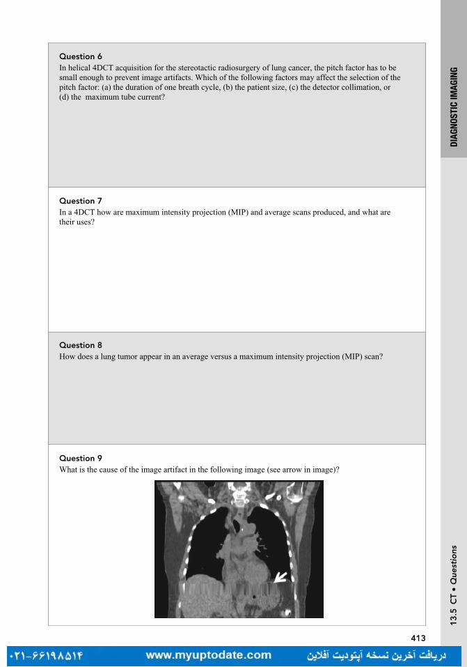
413
DIAG
NOST
IC IM
AGIN
G1
3.5
CT
• Q
uest
ions
Question 8How does a lung tumor appear in an average versus a maximum intensity projection (MIP) scan?
Question 7In a 4DCT how are maximum intensity projection (MIP) and average scans produced, and what are their uses?
Question 6In helical 4DCT acquisition for the stereotactic radiosurgery of lung cancer, the pitch factor has to be small enough to prevent image artifacts. Which of the following factors may affect the selection of the pitch factor: (a) the duration of one breath cycle, (b) the patient size, (c) the detector collimation, or (d) the maximum tube current?
Question 9What is the cause of the image artifact in the following image (see arrow in image)?

414
DIAG
NOST
IC IM
AGIN
G1
3.5
CT
• A
nsw
ers
Answer 8An average scan will smear the location of the tumor. It will look similar but not the same as a free breathing 3DCT. On a free breathing CT, the tumor’s center of the mass may shift, depending on the phase of the breathing at the acquisition. The tumor in the MIP scan will appear much larger, comprising the entire range of motion of the tumor. Because of the slow acquisition time, the center of the mass of the tumor observed in a cone beam CT (acquired for imaging verification) is more consistent with the center of the mass of the tumor in the average intensity projection (AIP) CT.
Answer 7The information contained in a 4DCT can be condensed into a single synthetic 3DCT using methods, such as MIP or average intensity projection (AIP). A MIP takes the maximum intensity of a given voxel in all phases of the 4DCT and assigns this as the intensity in the new 3DCT. Similarly, the AIP uses the average intensity of the voxel in the 4DCT. A minimum intensity projection is also available. Further, these projections can be determined over just a subset of the 4DCT phases. For example, if you plan to gate and treat just in the 80% to 100% phase, you would use just those images to create your MIP for planning.
Answer 6In 4DCT acquisition, the data sufficient condition (DSC) requires the data to be acquired within one breath hold; therefore, (a) is the correct answer.
Answer 9The artifact is caused by undersampling of prolonged irregular breathing pattern.
Pan T, Sun X, Luo D. Improvement of the cine-CT-based 4DCT imaging. Med Phys. 2007;34:4499
415
DIAG
NOST
IC IM
AGIN
G1
3.5
CT
• Q
uest
ions
Question 10Which of the following is the largest potential contributor to geometric inaccuracy of CT imaging: tube focal spot size, collimator, detector cell size, or location of the isocenter?
Question 11What scanner parameters (may be more than one) affect the spatial resolution of CT imaging: (a) focal spot size, (b) CT tube current, (c) helical pitch, or (d) reconstruction kernel (algorithm)?
Question 12Iodinated intravenous contrast is the most frequently used contrast agent in CT imaging. How does this agent work?
Question 13Which of the CT imaging tasks will benefit from the use of iodinated intravenous contrast?

416
DIAG
NOST
IC IM
AGIN
G1
3.5
CT
• A
nsw
ers
Answer 12Iodinated contrast works by increasing the number of photons attenuated within the vessels. Iodine’s k-edge is slightly lower than the effective photon energy from a CT X-ray beam; therefore, attenuation is much higher for the vessel filled with iodine contrast, providing image contrast.
Answer 10In CT, the location of the isocenter used in the image reconstruction should match the physical location of the isocenter. Any deviation from the assumed isocenter to the physical isocenter will cause geometric distortion and thus reduce accuracy; therefore, location of the isocenter is the largest contributor.
Answer 11(a) and (d) are the best answers. In general, a CT scanner has two focal spot sizes. The small focal spot is used for studies that require high resolution, such as the inner ear canal, whereas the large focal spot is used mainly for chest imaging and spinal and abdominal imaging, which do not require superior spatial resolution. The reconstruction kernel (sometimes called the reconstruction algorithm) can shape the frequency response of the CT projection data during the filtered back-projection reconstruction, either to boost or reduce the spatial resolution. In CT, the spatial resolution boost from the reconstruction kernel is at the cost of image noise (ie, high spatial resolution kernel brings higher image noise).
Answer 13Iodinated contrast requires blood flow. Solid lesions have enough blood supply to appear as areas of high intensity on the image, but cystic lesions do not have a blood supply; therefore, cystic lesions will appear as areas of low intensity (water-like) on contrast images. Imaging of lung nodules, kidney stones, or bone fractures would not be improved.
417
DIAG
NOST
IC IM
AGIN
G1
3.6
Ult
raso
und
• Q
uest
ions
Question 16The volume CT dose index (CTDIvol) can be determined using two different right cylindrical acrylic phantoms: a 16-cm diameter phantom for pediatric and head protocols and a 32-cm diameter phantom for adult body protocols. For measurements made in each phantom, with identical scan parameters, which will have a greater CTDIvol?
Question 15Scatter radiation to the CT detector is the main contributor to degraded CT image quality. Scatter radiation is primarily generated within the patient and secondarily from the hardware itself (such as from the second tube in a dual-source scanner). What is the major effect of scatter radiation on the CT image?
Question 14In CT, metal implants can cause severe image artifacts shown as bright or dark streaks/bands surrounding the metal object. What is the main cause of these artifacts?
Question 1 13.6 ULTRASOUNDWhich is the primary factor determining the axial resolution of B-mode (brightness mode) imaging?

418
DIAG
NOST
IC IM
AGIN
G1
3.6
Ult
raso
und
• A
nsw
ers
Answer 16CTDIvol determined from measurements in the 16-cm CTDI phantom will be greater than that from the 32-cm phantom given identical scan parameters (less attenuating material). If the CTDIvol is determined using the wrong phantom, the reported value will be overestimated if the 16-cm phantom was used for an adult body protocol or underestimated if the 32-cm phantom was used for a pediatric or head protocol.
Answer 15The main effect is CT number shift. If the detector receives excessive radiation, the total signal it generates increases, decreasing the apparent attenuation from the patient, and reducing the CT number.
Answer 14The main cause of metal artifacts is a paucity of photons penetrating the metal object. Secondarily, those photons that do penetrate the object to form the image are heavily filtered and will cause strong beam hardening artifacts.
Answer 1The spatial pulse length is the primary factor. As rule of thumb, the axial resolution = 1/2 × (spatial pulse length). The pulse amplitude will affect the B-mode signal strength. The center frequency will affect the attenuation of the signal. The width of the transducer element may affect the center frequency of the pulse.

419
DIAG
NOST
IC IM
AGIN
G1
3.6
Ult
raso
und
• Q
uest
ions
Question 4One of the fundamental physics principles governing ultrasound image quality is the attenuation coefficient of the pulse-echo signal. The attenuation coefficient is linearly proportional to the center fre-quency. For most soft tissues, what is this linear attenuation coefficient?
Question 2In ultrasound, what will provide the best benefit to the lateral resolution in the image (the lateral direction is perpendicular to the pulse transmitting direction)?
Question 3In ultrasound, transmit or receive gain is measured in the unit of decibels (dB). If the receive gain is 3 dB, what is the amplification factor for the output power versus the input power?
Question 5Doppler color flow imaging and power Doppler imaging both use color-coded pixel values to indicate blood flow information. What is the major difference between these two modes?
420
DIAG
NOST
IC IM
AGIN
G1
3.6
Ult
raso
und
• A
nsw
ers
Answer 4For most soft tissues, the linear attenuation coefficient is 0.5 dB/cm/MHz (ie, the attenuation is 3 dB/cm if the center frequency is 6 MHz, or the signal will decrease by half of its original strength for each centimeter of soft tissue traveled for a 6-MHz pulse).
Answer 3dB is log scale = 10 × log A, where A is the amplification factor. Since 3 dB = 10 × log 2, 3 dB means the output power is two times the input power.
Answer 2Placing the focal zone or multiple focal zones around the region of interest. In ultrasound, the best lateral resolution can be found at the center of the focal zone. All commercial ultrasound scanners should have multiple focal zones available, which will provide a wide range of depth with good spatial resolution. The tradeoff to these multiple focal zones is a slow frame rate.
Answer 5Color flow imaging can detect the flow direction, but power Doppler cannot. Power Doppler uses only the amplitude of the flow, not the phase; therefore, this technique is less sensitive to aliasing artifacts. However, power Doppler is more sensitive to flow information in small vessels.

421
DIAG
NOST
IC IM
AGIN
G1
3.6
Ult
raso
und
• Q
uest
ions
Question 8How does 3D ultrasound work?
Question 6How would lung, bone, air cavity, and bladder affect ultrasound shadowing artifact?
Question 7Reverberation artifacts in ultrasound are due to multiple reflections between a structure and the transducer or multiple reflections within a structure itself. Reverberations degrade image quality and may overlay lesions, potentially leading to misdiagnosis. Is there any simple way to reduce reverberation artifacts?
Question 9What is the frequency of the waves used in medical ultrasound devices? What is the speed of ultrasound in tissue?
422
DIAG
NOST
IC IM
AGIN
G1
3.6
Ult
raso
und
• A
nsw
ers
Answer 8Standard ultrasound scanning produces 2D images. 2D images at multiple depths may be taken. To get a true 3D image, sound waves are sent at different angles, instead of from one main direction in 2D ultrasound. Their echoes are then collected and processed in a similar way to CT reconstruction of transmitted X-rays.
Answer 7A simple method to reduce reverberations is to angle the probe slightly to avoid direct incidence onto a flat surface.
Answer 6Ultrasound shadowing artifacts are due to reduced echo intensity behind highly attenuating objects, such as an air cavity or a stone. The bladder is the least attenuating organ, it is unlikely to generate shadowing artifacts.
Answer 9Medical ultrasound devices typically operate in the 1 to 20 MHz range. Typically speed of ultrasound in tissue is 1,540 ms−1

423
DIAG
NOST
IC IM
AGIN
G1
3.6
Ult
raso
und
• Q
uest
ions
Question 11Why does native tissue harmonic imaging have a relatively large imaging depth even though it uses higher frequency echo signals to form images (second harmonic, ie, two times fundamental frequency)?
Question 10How is ultrasound frequency related to wavelength, and how does this affect resolution?
424
DIAG
NOST
IC IM
AGIN
G1
3.6
Ult
raso
und
• A
nsw
ers
Answer 11Native tissue harmonic is formed from the fundamental frequency sound waves traveling to depth or during the harmonic echoed return to the transducer. The harmonic component of the sound waves travels only one way, not both ways like the fundamental frequency sound wave component. Increased attenuation of the higher harmonic components only occurs during the portion of the trip in which they are present, reducing their attenuation. Therefore, native tissue harmonic imaging can still maintain significant imaging depth.
Answer 10The wavelength is inversely proportional to frequency. Hence, higher frequency waves have a shorter wavelength, while lower frequency waves have a longer wavelength. A high-frequency wave will give better axial resolution, but it will be attenuated more and will not penetrate as deep as a low-frequency wave. On the other hand, a low-frequency wave will penetrate deeper at the expense of resolution.

427
IMAG
E GU
IDAN
CEQ
uest
ions
Question 4What are the different systems used for image-guided radiation therapy (IGRT)?
Question 3What are some examples of both inter-fraction and intra-fraction variables that cause uncertainty in treat-ment targeting during radiation therapy?
Question 2What is the difference between accuracy and precision?
Question 1What is IGRT and why is it used?
Turn page to see the answers.

428
IMAG
E GU
IDAN
CEA
nsw
ers
Answer 4Electronic portal imaging device (EPID), two-dimensional kilovoltage imaging pair, stereoscopic kilovoltage images, megavoltage cone beam (MVCT), kilovoltage cone beam (kVCT), CT-on-rails (in-room diagnostic quality CT scan), optical tracking, in-room magnetic resonance imaging, ultrasound (US), electromagnetic transponders.
Answer 3Patient positioning/setup errors, weight loss, change in volumes, and bladder/rectum filling are a few examples of changes that can occur from fraction to fraction (inter-fraction). Patient movement during treatment, breathing, gas movement in the bowels, and cardiac motion are a few factors that can lead to uncertainty during treatment (intra-fraction).
Answer 2Accuracy is how close the measured value is to the true value. Precision is how close the measured values are to each other. It is possible to be precise without being accurate, and accurate without being precise. The aim of image-guided radiation therapy (IGRT) is accuracy.
Answer 1IGRT: image-guided radiation therapy. It is used to ensure that the treatment target is localized and aligned to the radiation beams as in the images that are used to plan the treatment before delivering radiation therapy.
429
IMAG
E GU
IDAN
CEQ
uest
ions
Question 7What is cone beam imaging and how is it different from a regular CT?
Question 6How does an electronic portal imaging device (EPID) work?
Question 5What is the process of image-guided radiation therapy (IGRT)?
Question 8What are the disadvantages and advantages of megavoltage computed tomography (MVCT) in radiation therapy?

430
IMAG
E GU
IDAN
CEA
nsw
ers
Answer 8Disadvantages: MVCT uses mega voltage energies where the Compton scattering dominates, so soft tissue is harder to visualize than in kV images where the photoelectric effect dominates. To obtain a good quality image you may need to increase the imaging dose, which causes an increase in radiation exposure to patients. Bony anatomy and tissue with low density (such as air cavity or lung) are visible.
Advantages: The artifacts from large implanted metals are minimized which makes the MV images easier to visualize the anatomy near metal implants than in kV images. The imaging beam and treatment beam also share the same isocenter, preventing potential mis-concordance between the imaging center and treatment center. Linear accelerator (linac)-based kV cone beam computed tomography (CBCT), however, requires a separate kV source that is placed orthogonal to the treatment beam with a discordance between the imaging and treatment center that could cause an offset between imaging and treatment.
Answer 7Cone beam imaging uses a cone-shaped X-ray beam that transmits onto a detector creating a complete volume image with one rotation. A regular CT images the patient with a narrow collimation creating a fan shaped X-ray beam. The narrow collimated beam images a thin “slice” of the patient. Therefore, while the fan beam rotates around the patient, the couch must slowly move along the longitudinal direction, resulting in a helical (spiral motion) of the X-ray beam, to fully image the patient.
Answer 6The incoming X-rays interact with the scintillation screen that converts them into optical wavelength photons. The optical photons are detected by the amorphous silicon photodiodes, which then are converted into an electronic signal and image.
Answer 5The IGRT process is similar among the different methods. The patient is first positioned on the treatment table in the same way they were simulated, using the room laser to align the machine isocenter with the marked isocenter on the patient body. Images of the patient are acquired using one of the listed IGRT systems. The acquired IGRT images are registered with the reference images, focusing on the specified anatomy. The registration is used to determine the initial patient offset required to align the target with the planned treatment beams. The repositioning software will display the offset as shifts for the treatment couch to align the patient in the same position as planned.

431
IMAG
E GU
IDAN
CEQ
uest
ions
Question 9What are the advantages of using CT-on-rails?
Question 11What is the Calypso 4D Localization system and how does it work?
Question 10What is infrared optical tracking and how is it used?
Question 12How is the optical tracking system different from that of the electromagnetic transponder system?

432
IMAG
E GU
IDAN
CEA
nsw
ers
Answer 12The optical tracking markers are placed on the surface of the patient’s body. The electromagnetic transponders are typically implanted into an organ (such as the prostate). This will provide a real time tracking method of the organ. The transponders are activated by radiofrequency waves. Both tracking methods are considered a form of image-guided radiation therapy (IGRT) because they are used for the same purpose of aligning the target with the planned treatment beams.
Answer 11The Calypso system has been referred to as a global positioning satellite (GPS) for the body, and is a common form of image-guided radiation therapy (IGRT) used for prostate patients receiving external beam therapy. Tiny transponder beacons (8.5 mm long, 1.85 mm diameter) are implanted into the prostate during an outpatient procedure. The locations of these transponders infer the prostate position and rotation. The Calypso tracking system communicates with these transponders via radio waves. Calypso systems can track the prostate position and motion in nearly real time (20 times a second).
During radiation delivery, users can set a prostate position threshold above which the radiation beam will be stopped. Using the Calypso system, high radiation doses can be confidently delivered to the target with tighter margins, sparing normal tissue, and reducing unwanted side effects.
www.varian.com/oncology/products/real-time-tracking/calypso-extracranial-tracking?cat=overview
Answer 10Optical tracking uses passive or active infrared markers that are detected by a camera. These markers are placed on the surface of the patient and are useful to detect both the patient position relative to the plan and whether the patient moves during treatment. A calibration method associates the camera’s coordinates with that of the isocenter of the treatment machine.
Answer 9CT-on-rails is a diagnostic quality CT located in the same vault as the linear accelerator (linac). It has the same quality images as the planning CT. This increases the accuracy of registering the treatment verification and planning images. The CT images taken with CT-on-rails can also be used for adaptive replanning purpose as they have accurate electron density information.

433
IMAG
E GU
IDAN
CEQ
uest
ions
Question 16Would megavoltage cone beam computed tomography (MV CBCT) be a good choice for imaging the prostate during image-guided radiation therapy (IGRT)?
Question 15Discuss the ultrasound (US) for external beam therapy.
Question 14What is a common imaging modality used for guidance during radioactive prostate seed implants? Briefly explain how it is used.
Question 13What are the benefits and disadvantages of the ultrasound (US) for image-guided radiation therapy (IGRT)?

434
IMAG
E GU
IDAN
CEA
nsw
ers
Answer 16For visualizing the actual prostate gland, it would be a poor choice since the MV beam suffers from poor soft-tissue contrast. However, MV CBCT is a common form of IGRT for prostate patients when used in conjunction with fiducials implanted into the gland. The fiducials are highly visible on the MV CBCT and can be used to align it to the reference image.
Answer 15In external beam, ultrasound provides soft tissue visualization for the prostate and breast cavity. During the simulation phase, US images can be taken and fused with planning CT images to provide better visualization of the target and surrounding structures. During treatment, US images allow target structures to be aligned using shape, size, and position of anatomy. Ultrasound is advantageous as an imaging method using nonionizing radiation.
Answer 14Real-time ultrasound (US) imaging is frequently used during the prostate seed implantation procedure. A trans-rectal US probe is used to capture a series of static images for planning purposes. It is also used to visualize the prostate, surrounding tissue, seeds, and needles during the actual implantation.
Answer 13US uses sound waves that are reflected back to the transducer and converts the signal to an image. The US is best used for localization of the prostate and the tumor cavity of the breast, because their locations permit for easy access of the US probe. US is noninvasive and does not produce ionizing radiation. It can be used daily to correct for motion and setup error. The disadvantage of using US is that it is operator dependent. Results may vary depending on how the operator applies the pressure to the probe.
435
IMAG
E GU
IDAN
CEQ
uest
ions
Question 20What is the van Herk formulation for margins?
Question 19Define gross tumor volume (GTV), clinical tumor volume (CTV), internal target volume (ITV), and planning target volume (PTV). What effect does image-guided radiation therapy (IGRT) have on these?
Question 18What is the difference between random and systematic errors and how do they affect the dose distribution around the clinical tumor volume (CTV)?
Question 17In terms of dose added to the patient’s treatment, arrange the following imaging modalities from least to greatest: megavoltage cone beam computed tomography (MV CBCT), planar kV, ultrasound (US), kilovoltage cone beam computed tomography (kV CBCT)

436
IMAG
E GU
IDAN
CEA
nsw
ers
Answer 20For 90% of the patient population, the clinical tumor volume (CTV) would receive 95% of the prescription dose cumulatively in conventional radiation therapy by using a planning target volume (PTV) margin = 2.5 × standard deviation (SD) of the systematic errors + 0.7 × SD of the random errors. Errors arise from organ delineation, motion, and setup.
van Herk M, Remeijer P, Rasch C, Lebesque JV. The probability of correct target dosage: dose-population histograms for deriving treatment margins in radiation therapy. IJROBP. 2000;47:1121-1135
Answer 19GTV is the gross, demonstrable extent of the tumor. CTV is the GTV plus additional volume to account for microscopic tumor spread. The ITV is a margin added to the CTV to account for internal physiological movements and position of the CTV during therapy. Finally, the PTV is the volume that includes the CTV and ITV, with an extra margin to account for patient movement, inaccuracies in beam and patient setup, and any other uncertainties. The use of IGRT may lead to a reduction in the margin between the CTV and PTV.
ICRU, Prescribing, Recording and Reporting Photon Beam Therapy Reports 50 & 62, 1993, 1999
Answer 18Random errors are unpredictable and can vary in magnitude and direction from fraction to fraction. This type of error leads to a blurring of the dose distribution around the CTV over the course of treatment. Systematic errors are deviations that occur during each fraction over the entire course of therapy. The deviation is in a similar size and direction and can lead to a shift in the dose distribution away from the CTV.
Answer 17US (zero dose), planar kV, kV CBCT, MV CBCT.

437
IMAG
E GU
IDAN
CEQ
uest
ions
Question 24Give a brief description of the ExacTrac system.
Question 23Describe a BB tray and its purpose?
Question 22Discuss the double-exposure technique that is commonly used for portal imaging.
Question 21What are some advantages and disadvantages of using magnetic resonance (MR) for image-guided radiation therapy (IGRT)?
438
IMAG
E GU
IDAN
CEA
nsw
ers
Answer 24ExacTrac is a closed loop image-guided radiation therapy (IGRT) system manufactured by Brainlab. ExacTrac uses two stereoscopic X-ray units recessed into the floor on opposite sides of the treatment table and two flat-panel detectors mounted to the ceiling. Patient positioning and movement can be monitored throughout the entire treatment with the integrated optical tracking system and stereoscopic X-rays can be acquired on demand to visualize internal anatomy.
www.brainlab.com/en/radiosurgery-products/exactrac/
Answer 23A BB tray, also known as a graticule or reticle, is a calibrated device with embedded radiographic markers arranged in a cross-like pattern. It is inserted into the tray slot on the linear accelerator. When a portal image is taken, the markers are visible on the image defining the isocenter, x- and y-axes, and scale. This device is mainly used, where the association of the beam isocenter and portal film is not known. Most new machines use a digital graticule where the machine isocenter relative to the electronic portal imager is defined and known.
Answer 22Portal imaging is used to verify patient position and proper beam shape and size. An exposure is taken with the shaped treatment field to record the treatment portal. Another exposure is taken with an open field to image the surrounding anatomy, allowing easy visualization of how the treatment field relates to this surrounding anatomy. The two exposures are superimposed on the same image.
Answer 21Advantages: Excellent soft tissue visualization, no radiation dose, and real-time tumor trackingDisadvantages: Variation in magnetic field can cause geometric distortion of patient images. The magnetic field can also interfere with dose distribution and the function of linear accelerator if no special shielding for the magnetic field is applied.

439
IMAG
E GU
IDAN
CEQ
uest
ions
Question 28Describe the In-Line kView imaging system that is used by the Siemens Artiste linear accelerator (linac).
Question 27What energy is typically used for kilovoltage cone beam computed tomography (kV CBCT)?
Question 26What are the advantages of using bowtie filters when performing cone beam computed tomography (CBCT) scans?
Question 25What are bowtie filters? Describe two types commonly used during cone beam computed tomography (CBCT).
440
IMAG
E GU
IDAN
CEA
nsw
ers
Answer 28For the Siemens Artiste linac, In-Line kView imaging uses a new MV beam that is produced through a carbon target without the flattening filter. This new imaging beam shifts the energy spectrum closer to the kV range and contains more low-energy X-rays, thus improving soft-tissue contrast when compared to a regular megavoltage cone beam computed tomography (MV CBCT) with the same dose. In-Line means that the imaging center is aligned with the iso-center of the treatment beam as is standard for MV CBCT.
www.healthcare.siemens.com/radiation-oncology/upgrades-and-options-for-your-linac/diagnosis-and-follow-up/cone-beam-ct-imaging-with-in-line-kview
Answer 27Common settings are in the 100 to 125 kVp range for machines equipped with kilovoltage X-ray tubes.
Answer 26Image quality is improved because cupping artifacts induced by X-ray scatter is decreased, and patient skin dose is reduced. Also, higher kVp energy X-rays can be used without saturating the detector, and there is reduced charge trapping in the detector.
Answer 25Bowtie filters are beam shaping devices for imaging X-rays that can improve the quality of CBCT scans. The half-fan and full-fan bowtie filters are the two common filters. A full-fan bowtie filter’s profile is thicker on both sides and thinner in the middle, resembling a bowtie (hence, the name). The thicker ends attenuate the beam more than the central area of the filter. This is usually used for CBCT head scans. A half-fan filter is thicker on one side and thinner on the other. The half-fan mode is used for body scans, where the detector is shifted laterally to increase the imaging axial field-of-view.

441
IMAG
E GU
IDAN
CEQ
uest
ions
Question 32How is CT-on-rails used in image guidance?
Question 31How does beam hardening affect cone beam computed tomography (CBCT)?
Question 30Discuss some differences between kV and MV dose deposition in the body.
Question 29Cone beam computed tomography (CBCT) can be acquired by rotating the gantry in a full or half arc. What are the advantages of using a half arc, and are there any disadvantages?

442
IMAG
E GU
IDAN
CEA
nsw
ers
Answer 32First, the patient’s external marks are aligned to the linear accelerator lasers. BBs are then placed on those marks. The patient is then rotated 180° using the column rotation toward the CT scanner and the CT is acquired. Since the isocenter of the linear accelerator and the acquisition center of CT are not associated, the isocenter coordinates from the two systems are manually associated by using the BBs on the CT image. After imaging registration, the difference between the set isocenter coordinates (BBs) and the reference planning isocenter coordinates is then calculated and displayed. This offset is manually applied after the patient is rotated back 180° and realigned to the linear accelerator lasers.
Answer 31When a polyenergetic X-ray beam passes through an object, lower energy photons are absorbed faster than higher energy photons. The mean energy of the beam increases, and it becomes “harder.” This can lead to artifacts in the CBCT.
Answer 30The depth of maximum dose (d
max) for typical kV imaging is essentially at the surface, therefore the
skin receives a higher dose than MV imaging. Due to the photoelectric effect, bone will also receive a higher dose in kV imaging than in MV imaging. Photons in the kV range are rapidly attenuated as depth in the body increases, as opposed to the photons in the MV range, which is characterized by a buildup, a maximum, and a much slower fall off.
Answer 29A half arc results in a faster scan, quicker reconstruction, and less dose to the patient. Also, critical surface structures can avoid irradiation, such as the lens of the eye. The trade-off is that images may be of lower quality, have greater noise and suffer from artifacts.

443
IMAG
E GU
IDAN
CEQ
uest
ions
Question 36Describe the Varian Real-Time Position Management (RPM) System used in radiation therapy?
Question 35What are the disadvantages of four-dimensional cone beam CT (4DCBCT)?
Question 34Describe the four-dimensional cone beam CT (4DCBCT)?
Question 33What are some of the registration methods used in image guidance?

444
IMAG
E GU
IDAN
CEA
nsw
ers
Answer 36RPM is a noninvasive and real-time tracking system used to measure the chest motion of a patient, which can be linked with the motion of a targeted tumor. It is best used for managing tumor motion in thoracic region and upper abdomen.
apps.varian.com/euen/oncology/radiation_oncology/clinac/rpm_respiratory_gating.html
Answer 354DCBCT requires a longer acquisition time, more imaging dose, and results in poorer imaging quality.
Answer 34The 4DCBCT is a technique used for image guidance of patients undergoing treatments of a moving target. The 4DCBCT provides a volumetric visualization of the tumor motion at the time of treatment.
Answer 33The methods used for image registration are the mutual information or normalized mutual information, visual alignment, landmarks, and surface matching.

445
IMAG
E GU
IDAN
CEQ
uest
ions
Question 40What is the typical range of radiation dose given by a kilovoltage cone beam computed tomography (kV CBCT), megavoltage cone beam computed tomography (MV CBCT), and CT-on-rails?
Question 39What is the six degrees of freedom (6DoF) couch?
Question 38What are the two main ways to divide the breathing cycle?
Question 37How does Real-Time Position Management (RPM) work?

446
IMAG
E GU
IDAN
CEA
nsw
ers
Answer 40The radiation dose from any of the in-room CTs varies with the technique used and what body part is imaged. The radiation dose given ranges from 10 to 50 mGy per scan, with CT-on-rails and kV CBCT giving lower doses than MV CBCT.
Answer 39The 6DoF couch refers to the movement of the couch in three-dimensional space. The couch moves in the translational directions (superior/inferior, left/right, and up/down) and in the rotational directions (pitch, yaw, and roll).
Answer 38The two types of breathing cycle binning (dividing the cycle into segments) are phase-binning and amplitude-binning. The phase is defined by selecting time points during the breathing cycle. The amplitude is defined by assigning thresholds in the breathing cycle.
apps.varian.com/euen/oncology/radiation_oncology/clinac/rpm_respiratory_gating.html
Answer 37An RPM system uses an infrared camera and reflective block placed on the patient to measure the respiratory cycle based on the movement of the chest. The measured respiratory cycle is recorded as a waveform. The physician uses this waveform to determine the gating thresholds for planning CT acquisition and gated treatment. During gated treatment, the beam will be automatically on if the breathing cycle is above the threshold and off if the breathing cycle is below the thresholds.
apps.varian.com/euen/oncology/radiation_oncology/clinac/rpm_respiratory_gating.html

447
IMAG
E GU
IDAN
CEQ
uest
ions
Question 44What other areas use fiducial markers?
Question 43How are fiducial markers placed in the prostate gland?
Question 42What are fiducial markers and how are they used for image-guided radiation therapy (IGRT) prostate treatments?
Question 41What methods could be applied to reduce the radiation dose to the patient when using the different types of CT used in image guidance?

448
IMAG
E GU
IDAN
CEA
nsw
ers
Answer 44Fiducial markers are not limited to the prostate and can be used for other treatment targets for which the onboard imaging contrast is insufficient to localize the target. The markers can be deliberately added, or may be surgery related such as stents (pancreas) or clips (eg, breast lumpectomy).
Answer 43During a transrectal ultrasound (US), a needle passes through the probe and inserts three markers into the prostate; at the apex, middle, and base of the prostate. This procedure is typically done in an urologist’s office.
Answer 42The prostate is difficult to visualize using the onboard X-ray imaging of a linear accelerator. Small fiducial markers made of gold, or other materials can be implanted into the prostate before the course of therapy. Once therapy begins, these markers are highly visible on pretreatment verification images. Their positions are compared to the reference images, and shifts are determined to ensure the prostate is in the correct treatment position.
Answer 41Radiation dose can be reduced by adjusting the image acquisition technique used (kVp, mAs, MUs); by minimizing the collimation/jaws to include just the body part of interest, and the use of appropriate filters.

449
IMAG
E GU
IDAN
CEQ
uest
ions
Question 48What is one difference between megavoltage cone beam computed tomography (MV CBCT) imaging on a conventional linear accelerator versus megavoltage computed tomography (MVCT) on a Tomo Therapy unit?
Question 47Is the megavoltage computed tomography (MVCT) on a TomoTherapy unit acceptable for daily use? What is the typical dose given during imaging?
Question 46How is imaging performed by a TomoTherapy machine?
Question 45What is the Calypso Surface Beacon transponder system?

450
IMAG
E GU
IDAN
CEA
nsw
ers
Answer 48On a conventional linear accelerator, imaging is performed using a cone-shaped beam that rotates once around the patient. On a TomoTherapy machine, a fan-shaped beam is used for scanning the patient helically, as the couch and patient move through the gantry.
Answer 47The imaging dose is dependent on setting used during the scan, and patient anatomy, but it is normally 1 to 3 cGy. Since this dose is relatively low, it is suitable for daily use. It may also be accounted for in the treatment plan.
Answer 46TomoTherapy uses a fan beam to image the patient prior to treatment. The 6 MV treatment beam is detuned to approximately 3.5 MV. Similar to a diagnostic CT, the fan beam is rotated around the patient while the treatment couch is translated through the machine. The exiting radiation is measured by a detector panel and reconstructed using filtered back-projection.
Yartsev S, Kron T, Van Dyk J. Tomotherapy as a tool in image-guided radiation therapy (IGRT): theoretical and technological aspects. Biomedical Imaging and Interv J. 2007;3(1):e16. doi:10.2349/biij.3.1.e16
Answer 45The Surface Beacon by Calypso is similar to the original Calypso system, but instead of being implanted, the radiofrequency beacon is placed on the patient’s surface. It can be used anywhere on the body to track intra-fraction motion (such as respiration) in real time.

451
IMAG
E GU
IDAN
CEQ
uest
ions
Question 52What are the factors that affect the quality of a digitally reconstructed radiograph (DRR)?
Question 51How is a digitally reconstructed radiograph (DRR) produced?
Question 50What is a DRR?
Question 49In terms of scan time, how does a diagnostic CT-scanner compare to TomoTherapy’s megavoltage com-puted tomography (MVCT), and to a cone beam computed tomography (CBCT) on a linear accelerator (linac)?

452
IMAG
E GU
IDAN
CEA
nsw
ers
Answer 52CT slice thickness, number of pixels, magnification of the DRR, and the step size are all factors that affect image quality.
Answer 51Using a virtual source position, ray lines are traced through the CT data to a virtual plane, at the distance of the imaging panel of the accelerator. The attenuation coefficients along each line are summed to produce an image at the virtual plane.
Answer 50A DRR, or digitally reconstructed radiograph, is a computer-generated projection image produced from CT data. It shows a beam’s-eye-view of the bony anatomy that can be compared to a portal image to check whether the patient is positioned as planned.
Answer 49A diagnostic CT-scanner, which can complete one rotation in a fraction of a second, is much faster than the MVCT on a TomoTherapy unit, which takes about 10 seconds per rotation. Newer CT-scanners also have a wider collimator, allowing them to image more of the patient in one rotation than TomoTherapy. A typical scan on the TomoTherapy unit can take 2 to 4 minutes depending on the extension of the patient scanned. This is longer than a CBCT scan on a linear accelerator, which takes around a minute, depending on gantry speed and arc length.
453
IMAG
E GU
IDAN
CEQ
uest
ions
Question 56Briefly describe ViewRay’s MRIdian system.
Question 55When compared with other image-guided radiation therapy (IGRT) systems, what are some of Vision RT’s advantages?
Question 54What is the Vision RT image-guidance system?
Question 53What equation is used to determine the attenuation along the ray lines used to construct a digitally reconstructed radiograph (DRR)?
454
IMAG
E GU
IDAN
CEA
nsw
ers
Answer 56MRIdian is an MR-based radiation-therapy system. It uses MR imaging to visualize soft tissue and perform gated therapy in real time, without the use of implanted fiducials or other invasive procedures.
www.viewray.com/system
Answer 55It can calculate source to skin distance (SSD) at any point on the patient during or after treatment, it allows users to define custom tolerances and will hold the beam automatically if they are exceeded, and it offers real-time monitoring and feedback. Additionally, internal fiducials or external markers on the skin are not necessary, and there is no imaging dose.
Answer 54Vision RTs main product is called AlignRT®. It is an optical surface-tracking system that uses two or three cameras, combined with a patterned-light projection, to visualize the surface of the patient’s body. This image is compared to a reference surface image generated by the treatment planning system to make sure the patient surface is positioned correctly. It also provides real-time motion tracking, which can warn therapists of movements and can even switch off the radiation if movements exceed tolerances.
www.visionrt.com/products_solutions/alignrt
Answer 53µ µ= +
w HU1,000
1
where µ is the linear attenuation coefficient of tissue, µw is the linear attenuation coefficient of water, and
HU is the Hounsfield unit.

455
IMAG
E GU
IDAN
CEQ
uest
ions
Question 59When using image-guided radiation therapy (IGRT), what is the difference between online and offline cor-rection? Which is more common?
Question 58Many image-guided radiation therapy (IGRT) systems allow for real-time imaging. How is this useful?
Question 57How is radiation delivered with the ViewRay MRIdian?

456
IMAG
E GU
IDAN
CEA
nsw
ers
Answer 59An online correction strategy is when corrections are made before and during patient treatment. The information provided by image guidance is used to determine appropriate action. This accounts for both systematic and random errors. Offline correction is performed by analyzing several of the images from initial treatments and deciding on a strategy for future treatments. This method will not eliminate random error. Presently, online correction is more commonly used.
Answer 58Preimaging a patient, with cone beam computed tomography (CBCT), for example, is helpful to ensure correct positioning, but real-time imaging can ensure the patient is positioned correctly throughout treatment. It shows if any motion is occurring during treatment, and allows for beam holding if the target strays too far out of tolerance. By observing motion in real time, physicians can determine if margins are adequate.
Answer 57The MRIdian uses three heads loaded with cobalt-60 and spaced 120° apart. The three treatment heads can irradiate a patient simultaneously to improve delivery efficiency. The MRIdian produces the equivalent of a 4 MV linear accelerator (linac) beam. The system also uses three multileaf collimators for beam shaping and advanced treatments, such as intensity-modulated radiation therapy (IMRT).

absorbed dose, 89accelerated partial-breast irradiation (APBI),
255–259accelerating power source for linear
accelerator, 43acceptance testing for linear accelerator, 347ACR. See American College of Radiologyactive breathing coordination (ABC), 289activity, 21, 25added filtration versus inherent filtration, 121adjacent photon fields, 187AEC. See automatic exposure controlair cavity treatment, effect of, 209air, energy absorption of, 95air-kerma-area-product rate (AKAP), 393air kerma rate, 391, 393air kerma strength, 229AKAP. See air-kerma-area-product rateALARA. See As Low as Reasonably Achievablealpha decay, 21alpha particles, 79, 81American Association of Physicists in Medicine
(AAPM), 347American College of Radiology (ACR), 371American Society of Radiation Oncology
(ASTRO), 347amu. See atomic mass unitanisotropy, 231anode of X-ray tube, 35anterior–posterior/posterior–anterior (AP/PA),
195, 307APBI. See accelerated partial-breast irradiationAP/PA. See anterior–posterior/posterior–
anteriorAs Low as Reasonably Achievable (ALARA), 359ASTRO. See American Society of Radiation
Oncologyatomic mass unit (amu), 5atomic number, 17, 21atomic structure, 7–15
attenuation coefficient, 419Auger electron, 11automatic brightness control (ABC), 389automatic exposure control (AEC),
389, 403average lifetime (T), 23average yearly exposure, 367Avogadro constant, 7
backscatter factor (BSF), 141balloon-based irradiation, 255BB tray, 437beam energy
change by flattening filter, 123effect on tissue-to-air ratio, 139
beam flatness, 123beam hardening, 37, 115beam quality, 115–117bending magnet in linear accelerator, 41beta decay, 19betatron, 53bias voltage of ionization chamber, 99binding energy of electron, 9B-mode imaging, 417bolus, 167, 221
versus compensator, 199use in electron therapy, 207
bowtie filters, 439brachytherapy, 225–235
accelerated partial-breast irradiation (APBI), 255
balloon, 259cervical cancer, 259loading systems, types of, 225ocular lesions, 239permanent versus temporary
implants in, 225physical states of radionuclides, 229
Bragg–Gray cavity theory, 89–91Bragg peak, 75, 321
Index
458
Index
breastirradiation, electrons use in, 221prone position, 173tangent fields treatment to, 181, 189treatment, 173
breast imaging, 399–403breathing cycle, 445bremsstrahlung, 31, 33, 77
energy spectrum of, 31spatial distribution of photons, 119
brightness mode (B-mode) imaging, 417BSF. See backscatter factorbuild-up caps for high-energy dose
measurements, 101buildup region, 137
Calypso, 431, 449cardiac pacemaker, treatment with, 353cathode of X-ray tube, 35CBCT. See cone beam computed
tomographyCerenkov effect, 83Cerrobend, 117, 191cervical cancer, brachytherapy, 251,
259, 261CFR. See Code of Federal Regulationscharacteristic X-rays, 69charged particle equilibrium (CPE), 91charged particle radiation, 53charged particles, 71, 79, 81, 315CI. See conformity indexclinical target/tumor volume (CTV), 279, 435cobalt-60 (Co-60), 51, 161, 301Code of Federal Regulations (CFR), 403
dose limit use for, 355limitation for single clinical breast
image, 403cold spots, 175collimator scatter factor (Sc ), 151, 153compensator vs. bolus, 199Compton scattering, 59–63, 67–69computation algorithms, used treatment
planning systems, 187computed tomography (CT), 251, 291, 417
geometric inaccuracy of, 415Hounsfield units difference in, 409in image guidance, 447iodinated intravenous contrast in, 415for proton treatment planning, 323quality of 4D to 3D, 411scanner parameters in, 415
computing, 291–294cone beam computed tomography (CBCT),
349, 429, 439, 441, 451QA for, 341
Conference of Radiation Control Program Directors (CRCPD), 367
conformal arc therapy versus dynamic conformal arc therapy, 283
conformity index (CI), definition of, 299
contrast agentsiodinated intravenous contrast for CT
imaging, 415used in MRI, 395
conventional radiography, 251coplanar deliveries versus noncoplanar, 277CPE. See charged particle equilibriumcranial fields, 177craniospinal fields, 175CRCPD. See Conference of Radiation Control
Program DirectorsCs-137, advantages and disadvantages of, 245CT. See computed tomographyCTDIvol. See volume CT dose indexCT-on-rails, 431, 441, 445CT simulator, 337CTV. See clinical target volume; clinical tumor
volumeCyberKnife system, 45cyclotron, 53
decay constant, 15, 21of I-125, 25
decay, types of, 15delta rays, 73depth of maximum dose (dmax), 137diagnostic CT-scanner, 451diagnostic X-ray
depth of maximum dose (Dmax) in, 387general range of kVps for, 387mammography, 399–403radiography and fluoroscopy, 387–393tube, 123
DICOM. See digital imaging and communication in medicine
DICOM-RT. See digital imaging and communication in medicine-radiation therapy
digital breast tomosynthesis, 401digital imaging and communication in medicine
(DICOM), 293digital imaging and communication in medicine-
radiation therapy (DICOM-RT), 293digitally reconstructed radiograph (DRR), 451,
453digital mammography, 401, 403diode detector, 105direct aperture optimization, 271directly ionizing radiation, differences in
indirectly ionizing radiation, 73dmax. See depth of maximum dosedose volume histogram (DVH), 185dosimeters, 97–112
absolute dosimeters, types of, 97for calibration of megavoltage linear
accelerators, 105characteristics of, 97for measurement of neutron dose, 109for radiation worker exposure
monitoring, 105

459
Index
for radioactive isotope leakage measurements, 107
for relative distribution of dose, 107for in vivo measurements, 107
dosimetry, 87–97of megavoltage beams, 87
double-exposure technique, 437double-focused multi-leaf collimator, 49DRR. See digitally reconstructed radiographdual focal spots, 39DVH. See dose volume histogramdwell positions, 257, 259dynamic-arc delivery, 343dynamic conformal arc therapy
versus conformal arc therapy, 283versus VMAT, 283
dynamic copper (Cu) filtration, purpose and effects on image quality, 391
effective dose equivalent (EDE), 363limit for member of public, 363limit for occupational worker, 365limit for pregnant occupational worker, 365
electromagnetic spectrum, 5electrometer correction factor, TG-51
protocol, 95electron arc therapy, 211, 215electron backscatter, variance with atomic
number and energy, 213electron beam profile flatness, 335electron beams, 33, 53, 205, 207, 339
virtual source of, 217X-ray contamination of, 207
electron cone, 219electron depth dose distribution, 215electron gun, 41electronic portal imaging device (EPID), 429electron isodose curves, 213electron mode, linear accelerator, 41electrons, 9, 321
changes in buildup region, 205charge and mass (MeV) of, 7, 9relative ranges of, 81use in breast irradiation, 221
electron shields, 215electron volt (eV), 5electrostatic accelerators, 51endometrial cancer, brachytherapy, 247–253end-to-end test, 345en face electron beam, 219EPID work. See electronic portal imaging
device workequivalent dose, 361equivalent square, 131, 169ExacTrac system, 437Excitation, 71, 81exponential decay, 21–28exposure, 87extrapolation ionization chamber, 101eye plaques, 239, 241
fat suppression, MRI, 395f factor, 87FFF linear accelerator. See flattening filter
free linear acceleratorfiducial markers, 447field size
depth of maximum dose variation as function of, 137
effect on tissue-to-air ratio, 139percent depth dose increase with, 137effect on R90 and Rp, 203
filament current, 115difference in tube current, 39
film, optical density of, 111flattening filter, 41, 123flattening filter free (FFF), 47, 127fluorescent yield, 13, 33fluoroscopy, 387–393
patient dose limits for, 3894DCBCT. See four-dimensional cone beam CT4D computed tomography (4DCT), 285,
411, 413four-dimensional cone beam CT (4DCBCT), 443four-field box technique, 187, 197frameless versus frame-based intracranial
SRS, 281free-air ionization chambers, 97Fricke ferrous sulfate dosimeter, 109
gamma camera imaging, 407Gamma Knife, 299–305gated treatment, 287, 289gating windows, 287Geiger counter, 107geometric penumbra, 169gradient search optimization, 267gross tumor volume (GTV), 185, 435
half beam block technique, 175half-life, 15, 23, 25, 301
activity formula of, 27decay constant, 15
half-value layers (HVLs), 37, 117, 123, 191HDR. See high-dose-rateheavy ions, 315
energy range for, 317heel effect, 37heterogeneity, 311high-dose-rate (HDR) brachytherapy, 25,
245–262, 337, 381, 383advantages and disadvantages, 229,
231, 245endometrial cancer, 247QA procedures, 339safety features and operational
interlocks, 231treatment of endometrial/cervical
cancer, 251hinge angle for wedged fields, 195
460
Index
hot spots, 167, 175, 221Hounsfield units (HU), 409HVLs. See half-value layershyperthermia, 327–332
temperature for, 327type of electromagnetic energy, 329
ICRP. See International Commission on Radiological Protection
ICRU. See International Commission for Radiation Units and Measurements
I-125, decay constant of, 25IGRT. See image-guided radiation therapyimage artifacts, cause of, 413, 417image-guided radiation therapy (IGRT), 427,
433, 435, 441, 447, 453magnetic resonance (MR) for, 437online versus offline correction, 455real-time imaging, 455ultrasound (US) for, 433
image intensifier, 391image magnification, 407IMRT. See intensity modulated radiation therapyIMRT QA. See intensity modulated radiation
therapy quality assuranceindirectly ionizing radiation, differences in
directly ionizing radiation, 73infrared optical tracking, 431inherent filtration, 39, 121inhomogeneity index, 301initial dose rate (cGy/h) of implant, 237In-Line kView imaging system, 439integral dose, 125intensity modulated radiation therapy (IMRT),
265–275, 285, 353advantages and disadvantages of, 269versus conventional radiation therapy,
265, 273delivery, 265, 267direct aperture optimization and traditional
two-step, 271objective function, 275objective types, 273, 275sliding window (dynamic), 267step-and-shoot (static), 265, 267
intensity modulated radiation therapy quality assurance (IMRT QA), 267
intensity modulation in proton beam, 271internal target volume (ITV), 279, 435International Commission for Radiation Units
and Measurements (ICRU), 183, 227, 251International Commission on Radiological
Protection (ICRP), 363interstitial brachytherapy, 241, 243, 253intra-mammary (IM) nodes, tangent fields
treatment to, 181intraoperative radiation therapy (IORT), 47, 211inverse-square law (ISL), 49, 133, 141in vivo dose measurements, 105, 107iodinated intravenous contrast, 415
ion chambers, 95polarity changes of, 93
ionization, 71, 81ionization chambers, 89, 99, 109
bias voltage to, 99correction for ion recombination, 95versus diode detector, 105extrapolation, 101parallel plate, 101polarity changes of voltage in, 93sealed versus open, 101
ionizing radiation, 71particle interactions, 71–84photon interactions, 59–70
IORT. See intraoperative radiation therapyIr-192, 229irradiated volume, definitions of, 183irregular fields, dose calculations from, 149ISL. See inverse-square lawisobar, 11, 17isocenter, 41, 171isodose lines, 125, 147isomer, 11, 15, 17isotone, 11isotopes, 11, 301
for permanent implants, 235ITV. See internal target volume
junction point, 175
KERMA, 67, 97kilovoltage cone beam computed tomography
(kV CBCT), 435, 439, 445klystron, 43kV CBCT. See kilovoltage cone beam computed
tomographykV diagnostic X-ray tube, 115kV versus MV dose deposition, 441
lateral tangent beam, angle of, 173LDR brachytherapy. See low-dose-rate
brachytherapyLET. See linear energy transferlifetime limit for radiation worker, 361light field, 339linac. See linear acceleratorlinac-based stereotactic radiosurgery (SRS), 299
equipment and imaging for, 305Gamma Knife versus, 305
linear accelerator (linac), 41, 179, 335absolute output calibration of, 335accelerating power source for, 43bending magnet in, 41cone beam computed tomography (CBCT)
on, 451monitor chamber in, 43order of components, 45quality assurance, 339
linear attenuation coefficient, 419

461
Index
linear energy transfer (LET), 75, 77low-dose-rate (LDR) brachytherapy, 227–244lung cancer
high-energy photons in treatment of, 135stereotactic radiosurgery of, 413
lung stereotactic body radiation therapy (SBRT), 283, 285
magnetic resonance imaging (MRI), 251, 285, 393–399
atomic mass number requirements for, 395contrast agents used in, 395for IGRT, advantages and
disadvantages, 437in-plane spatial resolution and estimation for
MRI units, 397magnetic field strength (B0), 397
magnetic resonance spectroscopy, 399magnetron, 45mammographic imaging, 399, 401
anti-scatter grids, 401calcifications, 399reason for breasts compression, 399
margins, van Herk formulation for, 435mass stopping power of charged particle, 79maximum intensity projection (MIP), 413Mayneord F factor, 133medical event (misadministration), 373, 375medium-dose-rate brachytherapy, dose rate
ranges for, 227megavoltage computed tomography
(MVCT), 449advantages and disadvantages of, 429
megavoltage cone beam computed tomography (MV CBCT), 433, 435, 445
megavoltage X-ray beam, quality of, 127metal–oxide semiconductor field-effect
transistors (MOSFETs), 111microtron, 53MIP. See maximum intensity projectionMLCs. See multileaf collimatorsMobetron, 45monitor unit (MU), 139, 271, 273
calculation, 149–164MOSFETs. See metal–oxide semiconductor
field-effect transistorsMRI. See magnetic resonance imagingMU calculation. See monitor unit calculationmultichannel vaginal cylinder, 251multileaf collimators (MLCs), 193, 269, 341, 343
double-focused, 49interplay, 271over-travel distance for, 269penumbra for, 193QA test for, 343transmission through, 193
MV CBCT. See megavoltage cone beam computed tomography
MVCT. See megavoltage computed tomography
National Council on Radiation Protection and Measurements (NCRP), 363
NCRP. See National Council on Radiation Protection and Measurements
negligible individual risk level (NIRL), 361neuroimaging, benefits to MR spectroscopy in,
399neutron beams, 55neutron dose measurement, dosimeters used
for, 109neutron interactions with matter, types of, 81neutrons, 9, 325, 327, 379neutron therapy, 325, 327NIRL. See negligible individual risk levelnoncoplanar deliveries versus coplanar, 277nonionizing radiations, examples of, 71nonstochastic (deterministic) effects versus
stochastic, 375NRC. See Nuclear Regulatory Commissionnuclear binding energy, 17nuclear medicine imaging, radioisotope used
in, 407Nuclear Regulatory Commission (NRC), 245,
355, 367dose limits, 355
nuclear structure, 7–15nucleus, 15, 17
OAR. See organs at riskoblique beam, 199oblique surface, effect of treating on, 207occupancy factor (T), 377ocular lesions, 239off cord, 189online versus offline correction, IGRT, 455optical density of film, 111optically stimulated luminescence detector
(OSLD), 103optical tracking system, 431organs at risk (OAR), 275OSLD. See optically stimulated luminescence
detector
pair production, 61, 63minimum energy of incident photon for, 65
parallel hole collimator-to-object distance, 407
parallel opposed beams, 125, 169parallel plate ion chamber, 101Paris system, 243particle interactions, 71–84particle therapy, 315–327patient orientation, 313patient safety, 347–356patient skin dose, cumulative air kerma
equivalent to, 389Patterson–Parker (Manchester) system, 241, 243PDD. See percent depth dosepeak scatter factor (PSF), 141
462
Index
penumbra, 121, 169, 193, 301percent depth dose (PDD), 129, 143
calculations of, 147definition for given field size, 129increase with field size, 137, 139percent change per centimeter for cobalt
photons, 131relationship of TAR, ISL and PSF
with, 141shape of megavoltage central-axis, 129
permanent implants, 225, 235PET imaging
benefits of CT scan with, 403causes of quantitative error in, 409radiopharmaceutical in, 405shielding, 381sources of variability with SUV, 405in 2D or 3D mode, 409
phantom scatter factor (Sp), 151, 153photodisintegration, 61photoelectric effect, 59, 61, 63–69photon interactions, 59–70photon mode, linear accelerator, 41physical wedge
beam quality, 117wedge angle for, 47wedge transmission factor, 47
Picture Archiving and Communication System (PACS), 293
pions, 317, 319pitch factor, 413planar kV, 435Planck’s constant, 7planning target volume (PTV), 185, 279, 435point A, 261point B, 261portal imaging, 437positron annihilation, 77postimplant dosimetry, purpose of, 237power Doppler imaging versus Doppler color
flow imaging, 419pregnancy, 353pressure correction factor, 93primary barrier shielding, equation for, 375projected focal spot, size at central axis, 39prone position, breast cancer in, 173prostate implant, 27, 241
dose rate of, 25dosimetric parameters for, 235procedure, 239radiation safety precautions, 241TG-43 calculation for, 237
proton beams, 325beam penumbra in, 121disadvantages of, 325intensity modulation in, 271
protons, 9, 81, 319advantage of, 53dose distribution for, 323range of, 53
relative biologic effectiveness of, 321treatment planning, 323
proton therapy, 319, 323PSF. See peak scatter factorPTV. See planning target volumepulse-echo signal, attenuation coefficient of,
419
QA. See quality assurancequality
patient safety, 347therapy equipment quality assurance,
335–347quality assurance (QA), 341, 351, 353
action levels for, 353annual, 335for CBCT imaging-guidance systems, 341on CT simulator, 337on HDR machine, 339on linear accelerator (linac), 335, 339for multileaf collimators (MLCs), 343procedures, 339, 343on treatment planning systems (TPS),
343, 345quantitative error in PET, 409Quimby system, 243
radiation area, dose limit for, 381, 383radiation badges, NRC requirements, 367radiation generating equipment
linear accelerators, 41–50particle and source-based radiation, 51–56production of X-rays, 31–40
radiation safety and regulationsrules and regulations, 359–375shielding, 375–384
radiation source strength, 227radiation, types of, 227radiation worker
dose limit for, 365lifetime limit for, 361
radioactive materials (RAM), 235, 349medical event for, 373TI on package of, 369transportation labels, 369transport of, 369
radioactive prostate seed implants, 433radioactive source, 231, 359
anisotropy with respect to, 231radioactivity, 15–21
units of, 3radiochromic film, 109radiographic film, 107, 109radiography, 387–393
patient dose limits for, 389radioisotope in nuclear medicine imaging, 407radionuclides
for brachytherapy treatments, 227specific activity of, 23
463
Index
radiopharmaceutical, 359in PET imaging, 405
radiosurgery devices, mechanical tolerance for, 297
radiotracer biodistribution, administration of therapeutic dose, 407
random versus systematic errors, 435Rayleigh scattering, 59, 61reactor-produced materials, 349real-time imaging, image-guided radiation
therapy (IGRT) for, 455Real-Time Position Management (RPM), 445record and verify system, 291record of medical event
(misadministration), 375rectangular field, depth dose for, 207reference conditions, 149registration methods in image guidance, 441rem, Sievert (Sv) and, 3respiratory motion and management,
287–290surface trackers for, 289
reverberation artifacts, 421R90, field size dependence of, 203robust planning, 323roentgen (R), 3
definition of, 87quantity in SI units, 87
Rp, 203field size dependence of, 203
R-to-cGy conversion factor, material and energy dependency, 89
SAD. See source to axis distanceSBRT. See stereotactic body radiation
therapySc. See collimator scatter factorsealed ion chambers versus open ion
chambers, 101secondary barriers, 377secular equilibrium, 15seed activity, 241sensitivity, parallel hole collimator-to-object
distance on, 407shielding, 375–384
equation barrier for protection (P) in, 377
Sievert (Sv) and rem, 3simulated annealing optimization, 267single-photon emission CT (SPECT), benefits of
CT scan with, 403six degrees of freedom (6DoF) couch, 445skin collimation, 205slice-select gradient on image
thickness, 395sliding window (dynamic) IMRT versus step-and-
shoot (static), 267sloped surface, effect of treating on, 207SOBP. See spread-out Bragg peaksource strength, 229
source to axis distance (SAD), 49, 181source-to-skin distance (SSD), 49, 171, 175, 177,
179, 181, 203equation for monitor unit calculation
using, 155estimation of PDDs for, 133monitor unit calculation, 159
Sp. See phantom scatter factorspatial resolution, parallel hole collimator-to-
object distance on, 407specific activity, 5, 23specific ionization (SI), 73SPECT. See single-photon emission CTSpencer–Attix cavity theory, 91spinal fields, 175, 177
skin gap for, 175spoiler screen, purpose of, 309spread-out Bragg peak (SOBP), 321, 323SRS. See stereotactic radiosurgerySSD. See source-to-skin distancestandardized uptake value (SUV), 405standing wave, advantage of, 43Stanford technique for total skin irradiation, 313step-and-shoot delivery, 343
versus sliding window (dynamic), 267stereotactic body radiation therapy (SBRT), 111,
275–286, 299characteristics of, 275guidance techniques, 279linear accelerator (linac) quality
assurance, 339lung, 279, 285patient immobilization devices, 281spine treatment planning, 277, 285treatment, 275, 281, 283, 355
stereotactic frame, 281stereotactic radiosurgery (SRS), 111, 297–306
characteristics of, 297frameless versus frame-based
intracranial, 281Gamma Knife, 303linear accelerator (linac) quality
assurance, 339stochastic (deterministic) effects versus
nonstochastic, 375stopping power, 79sulfur hexafluoride (SF6), linear accelerator, 43surface dose, 199
field size increases, 197tray-to-skin distance decreases, 197
surface trackers for respiratory motion, 289symmetry, 335systematic errors, random versus, 435
TAR. See tissue-to-air ratiotarget to film distance (TFD), 171TBI. See total body irradiationtemperature correction factor, 93temporary implants, permanent versus, 225TFD. See target to film distance

464
Index
TG-43 calculation for prostate implants, 237TG-51 protocol
calibration of ion chambers, 109determination of electrometer correction
factor, 95dosimeters used for megavoltage linear
accelerators, 105equation for calibration of linear
accelerators, 91temperature and pressure correction
factor, 93thermal enhancement ratio, 331thermoluminescent dosimeter (TLD), 101
accuracy of, 103materials used in, 103versus metal–oxide semiconductor
field-effect transistors, 111versus optically stimulated luminescence
detector, 103Thoraeus filter, 1193D computed tomography (3DCT), imaging
dose and quality of 4DCT to, 4113D conformal radiation therapy. See three-
dimensional conformal radiation therapy3DCT. See 3D computed tomography3D imaging, advantages and disadvantages
of, 409three-dimensional (3D) conformal radiation
therapy, 271, 273versus IMRT, 265
3D ultrasound, 421three-field technique, 197three-phase liver CT study, 411TI. See transport indextime-of-flight (TOF), 409time-out, 351tissue lateral effect, 125tissue maximum ratio (TMR), 157
definition of, 143monitor unit calculation using, 139relation to tissue-to-air ratio, 143
tissue-to-air ratio (TAR), 183effect field size and beam energy, 139relationship of PDD, ISL and PSF with, 141relation to tissue maximum ratio, 143
TLD. See thermoluminescent dosimeterTMR. See tissue maximum ratioTOF. See time-of-flightTomoTherapy, 45, 449, 451total body irradiation (TBI), 307–311
dose rate, 309photon energies, 309techniques, 311
total skin irradiation (TSI), 311–315Stanford technique for, 313
TPS. See treatment planning systemstransient equilibrium, 15transport index (TI), 369traveling wave, 43treated volume, definitions of, 183
treatment planning systems (TPS), 343computation algorithms used, 187CT images in, 345dose calculation for, 345QA procedures on, 343
TSI. See total skin irradiationT2-weighted MRI image, 393tube current (mA), 39, 115tube voltage, 39, 115TVL, 379
ultrasound, 435benefit to lateral resolution in image, 417frequency of waves in, 421frequency relation to wavelength, 423for IGRT, benefits and disadvantages of, 433measurement of transmit or receive gain in
dB, 417shadowing artifact, 421in tissue, speed of, 421
uncharged particles, examples of, 71uniform dose distribution, 173use factor (U), 375
for secondary barriers, 377
vaginal cylinder treatment, 247, 253van Herk formulation for margins, 435Varian Real-Time Position Management (RPM)
System in radiation therapy, 443ViewRay’s MRIdian system, 453, 455virtual wedge, 117Vision RT image-guidance system, 453VMAT. See volumetric modulated arc therapyvolume CT dose index (CTDIvol), determination
of, 417volumetric imaging, advantage of, 251volumetric-modulated arc therapy (VMAT),
269, 273delivery, 343versus dynamic conformal arc therapy, 283
water equivalent phantoms, 95wedge angle, 47, 125wedged fields, hinge angle for, 195wedged isodose distribution, 49, 125wedges, 189, 197
transmission factor, 47, 171
X-ray-based angiography, 389X-ray contamination of electron beam, 207X-ray intensity, tube current and tube
voltage, 39X-ray tube, 31–35
components of, 33thin and thick targets, 35
yttrium-90 (Y-90), for targeted radionuclide therapy, 407
Zeiss intrabeam, 47