Physics 332physics.oregonstate.edu/~giebultt/COURSES/ph332/Labs/lab0-21.pdfExperiment . 5:...
25
olt/S: "" 332 T I Tl.E. PH 332 LfIIl HAHUI\l. AUTHOR: DEPT IHST: !!I\IIIIOH \1\1 \1 TEXT Physics 332 Vision and Lab Manual ©9/93 Department of Physics This publication cannot be copied or reproduced without the express written permission of the OSU Department of Physics. For copyright permission, please contact OSU, Department of Physics, 301 Weniger Hall, Corvallis, OR 97331-6507
Transcript of Physics 332physics.oregonstate.edu/~giebultt/COURSES/ph332/Labs/lab0-21.pdfExperiment . 5:...

olt/S: "" 332 T I Tl.E. PH 332 LfIIl HAHUI\l. AUTHOR: DEPT IHST: !!I\IIIIOH
\1\1 \1 '1~ TEXTPhysics 332
~Light, Vision and Color~
Lab Manual
©9/93 Department of Physics
This publication cannot be copied or reproduced without the express written
permission of the OSU Department of Physics. For copyright permission, please
contact OSU, Department of Physics, 301 Weniger Hall, Corvallis, OR 97331-6507

TABLE OF COITEITS
PAGE
INTRODUcrION•••••••••••••••• ~ •••••••••••••••••••••'•••••••••••••••••••••••• 1 F•••••• <••••••••••••••••••••••••••••••••••••••••••••EQUIPt1ENT ••••••••••••••• 2
RAY OPrICS SE'I'tJP•••••••••••••••••••••••••• ~ •••••••••••••••••••••••••• ~ ••••6
BASIC EIPKRIKKKTS
Experiment 1: Introduction to Ray Optics •••••••••••••••••••••••••••••8 • Experiment 2: The Law of Reflection............................. "•••••10 Experiment 3: Image Formation in a Plane Mirror •••••••••••••••••••••• 12 Experiment 4: The Law 6f Refraction••••••••••••••••••••••••••••••••• 14 Experiment 5: Reversib~l'ity •••••••.•••••• ~'••••••••• ,_ •••••••••••••••••16 Experiment 6: 'Dispersion and Total Internal Reflection••••••••••••••18 Exp~riment 7: Converging Lens: Image and Object Relationships •••••••20 Experiment 8: Light and Color."•••••••••••••••••••••••• '•••••••••••••• 22 Experiment 9: Two-Slit Interference.................... ~ ..............24 Experiment 10: Polarization•••••••••••••••"•••••••• ~~••••••••••••••••••26
'ADYHCED EIPKRIIIEII'l'S
Experiment 11: Image Formation from Cylindrical Mirrors ••••••••••••••28 Experiment 12: Image Formation from Spherical Mirrors ••••••••••••••••31 Experiment 13: Image Formation with Cylindrical Lenses•••••••••••••••34 Experiment 14: Spherical Lenses: Spherical and Chromatic
Aberation, Aperture Size, and Depth of Field••••••••••38 Experiment 15: The Diffraction Grating•••••••••••••••••••••••••••••••40 Experiment 16: Single Slit Diffraction•••••••••••••••••••••••••••••••42 Experiment 17: General Diffraction•••••••••••••••••••••••••••••••••••44
OPTICAL IISTRUKEBTS
Experiment 18: Introduction••••••••••••••••••••••••••••••••••••••••••47 Experiment 19: The Projector •••••• ,•••••••••••••••••••••••••••••••••••49 Experiment 20: The Ma.gnifier •••••••••••••••••••••••••••••••••• ; ••••••50 Experiment 21: lhe Telescope ••••••••••••••••••••••••••••••••••••••••• 52 Experiment 22: The Compound Microscope •••••••••••••••••••••••••••••••S4
APPEJlDIX................................................................ 56


INTRODUCTION
Information comes to us through all our five senses, bu t most of us rely primarily on our sense of sight to inform .us of the world around us. Because of this, the nature of light plays a critical role in our experience. Certainly our view of the world is colored (pun intended) by the nature of the medium which brings us so much information about ·it: light.
In our day to day life, we rarely concern ourselves with light, except perhaps when there is too much or not enough of it. We interact with light that has interacted with objects to determine such things as the color, shape, and position of the objects. But our attention is almost always on the objects, not on the light that· brings us the information.
In studying· optics we change the focus of our attention. We still gain our information by i.pteracting with light that has interacted with objects. But in studying optics we want to know what our observations tell us, not about the objects, but about light itself.
Before plunging into your experimental investigations of optics, its a good idea to become familiar with the equipment you will be using. The Equipment section of this manual will help you identify each of the components included with your optics system. The section entitled Ray Optics Setup gives some useful tips for aligning the optical equipment.
1

EQUIPMENT
Optics Beach
/
Component Holder
Ray Table Alignnent Rail/
/Ray Table Base
Optics Beach
The Optics Bench Is shown above. The Light Source, Component Holders, and Ray Table Base all attach magnetically to the bench as shown. For proper optical allgnment, the edge of each of these components should be mounted flush to the aUgnment rall.
NOTE: Care should be taken not to scratch or abuse the surface of the magnetic pads. Should the surfaces become dirty, use only soapy water or rubbing alcohol for cleaning. Other solvents may dissolve the magnetic surface.
Iacaadesceat LICht Source
Filament Knob
Bulb
Notch Showing Location of
lacaadesceat Light Source
To turn the light source on. connect the power cord to any grounded 105-125 VAC receptacle. and flip the switch on the rear panel to ON. If at any time the light falls to come on, check with your instructor.
The Filament Knob on the top of the unit moves the Ught bulb from side to side.
2
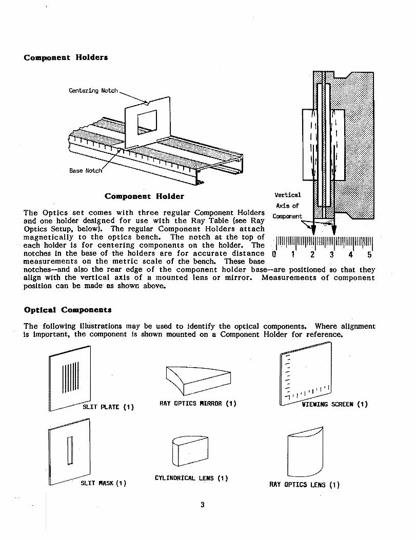
Component Holders
Centering Notch
Component Holder Vertical
Axis of The Optics set comes with three regular Component Holders Caq:Jonant and OJlle holder designed for use with the Ray Table (see Ray Optics Setup, below). The regular Component Holders attach
::c~n;~\~:~l{s t~o:h~e~i::f:g b~:~~~ne~~: ~~t~:ea~o~~:/oPT~! .. 1"111111111111111111"1111111111111111111111111111 notch~s in the base of the holders are for accurate distance 0 1 2 3 4 5 measurements on the metric scale of the bench. These base notches--andalso the rear edge of the component holder base--are positioned so that they align with the vertical axis of a mounted lens or mirror. Measurements of component position can be made as shown above.
Optlc;al Components
The following Uhistrations may be used to identify the optical components. Where alignment is impbrtant, the component is shown mounted on a Component Holder for reference.
:...:-"'I--........ ~I
RAY OPTICS ~IRROR (1)
CYLINDRICAL LENS (1) RftY OPTICS LENS (l)
3

DIFFRACTION SCAlE (1) (Shown mounted on Ray Table Base)
VARIABLE APERTURE (2 PLATES) (Shown mounted on Component Holder)SPHERLCAl LENSES (3) I
(Sh:rmounted on ~onent Holder) 751 _ FOCAl.. LENGTH CONVEX LENS 1~ _FOCAl LENGTH CONVEX LENS -1rO - FOCAL LENGTH CONCAVE LENS
VIRTUAl.. IRAGE LOCATORS (2)
COLORED FILTERS (J) Red, Creen, Blue/Green
5Q _ FOCAl.. LENGTH CONCAVE RIRROR(I """,tal on eoo."anont Holder)
CROSSED ARROW TARGET (1) POLARIZERS (2) (Shown mounted on ~onent Holder)
4

I I
OIFFRACTIOH GRATING it1t UH£SiI;nI
DIFFRACTION GRATING (1)DIFFRACTION PLATE (1) (5276 Lines/em)
The aperture patterns in the Diffraction Plate, and their dimensions, are shown below.
o E
+
DIFFUCTIOK PLATE APERTURES
PA'ITERN NO. SLITS SLIT WIDTH (mm) SLIT SPACING (mm)
A 1 .04 B 1 .08 C 1 .16 D 2 .04 .125 E 2 .04 .250 F 2 .08 .250 G 10 .06 .250 H 2 (crossed) .04
I 225 Randomly Placed Circular Apertures (.06 mm dia.) J 15 x 15 Array of Circular Apertures (.06 mm dia.)
5

RAY OPTICS SETUP
Ray Table Component Holder
f Ray Table and Base
Basic Ray Optics Setap
The basic setup for Ray Optics is shown above. The Ray Table Base should be flush against the alignment rail. The Ray Table fits over the pin on the top of the base.
Notice that the Ray Table Base Is slightly slanted. When mounting the base on the Optics Bench, always be. sure the Ray Table slants .down toward the..Llght Source. This ensures sharp, bright rays. (In all the experiments described In this manual, the error introduced by this tilt Is negligible.)
Either side of the Ray Table may be used. One side has .a rotational scale, the other has both a rotational scale and a grid that may be used for linear measurements.
The Slit Plate is attached to a component holder between the Light Source and the Ray Table. The positioning shown in the lliustration will give clear, sharp rays In a slightly darkened room. However, the quality of the rays Is easily varied by adjusting the distance between the Light Source and the Slit Plate. Narrower, less divergent rays may be obtained by slfdlng the Light Source farther away from the slits, but there Is a corresponding loss of brightness.
The Ray Table Component· Holder attaches magnetically to the Ray· Table as sho~ It may be used to mount the Viewing Screen, Polarizer, or other component.
SIBcle Ray Setap
Single Ray Setap
Most quantitative ray optics experiments are most easily performed with a single ray. This can be obtained by usIng the Slit Mask, as shown above, to block all but the desired ray.
6

For accurate measurements using the rotational scale, the incident ray must pass directly through the center of the Ray Table. To accomplish this, alternately adjust (1) the lateral position of the Slit Plate on its Component Holder, (2) the position of the filament with respect to the optical axis, and (3) the rotation of the Ray Table.. When one of the rays is aligned in this manner, place the Slit Mask on the other side of the Component Holder to block all but the desired ray.
Parallel Ray Setup
Ray Optics Lens
Parallel Ray Setup
Parallel rays are obtained by positioning the Ray Optics Lens between the Light Source and the slits, as shown above. Use the parallel lines of the Ray Table grid as a reference, and adjust the longitudinal position of the Ray Optics Lens until the rays are parallel.
7

BASIC EXPERIMENTS
Experiment 1: Introduction to Ray Optics
EQUIPMENT NEEDED: Optics Bench, Light Source, Ray Table and Base, Component Holder, Sllt Plate, Ray Table Component Holder, Viewing Screen.
Viewing Screen
Equipment Setup
Setup the equipment as shown above, and, turn on the Light Source. Darken the room enough so the Ught rays on the Ray Table are easily visible.
STRAIGHT LINE PROPAGATION OF LIGHT
Observe the light rays on the Ray Table.
1. Are the rays straight? _____________________---:
2. How does the width .and distinctness ·o{. each ray vary with the distance from the Slit Plate?
•
Rotate the Slit Plate slowly on the .component .holderuntil"the>sUts are horizontal. Observe the sUt images on the Viewing Screen.
3. How does the width and distinctness of tbe sIlt images depend on the angle of the Sltt Plate?
•
4. For what angle of the Slit Plate are the images most distinct? For what angle are the images least distinct?
8
5. On a separate sheet of paper, explain your observations in terms of the straight line propagation of light. Include a diagram showing how the width of the slit images depends on the orientation of the Light Bulb filament with respect to the Slit Plate.
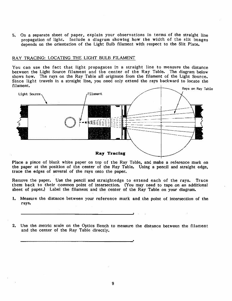
RAY TRACING: LOCATING THE LIGHT BULB FILAMENT
You can use the fact that light propagates in a straight line to measure the distance between the Light Source filament and the center of the Ray Table. The diagram below shows how. The rays on the Ray Table all originate from the filament of the Light Source. Since light travels in a straight line, you need only extend the rays backward to locate the filament.
Ray Tracing
o
Place a piece of blank white paper on top of the Ray Table, and make a reference mark on .the paper at the pOSition of the center of the Ray Table. Using a pencil and straight edge, trace the edges of several of the rays onto the paper.
Remove the paper. Use the pencil and straightedge to extend each of the rays. Trace them back to their common point of intersection. (You may need to tape on an additional sheet of paper.) . Label the filament and the center of the Ray Table on your diagram.
1. Measure the distance between your reference mark and the point of. intersection of the rays.
2. Use the metric scale on the Optics Bench to measure the distance between the filament and the center of the Ray Table directly.
9
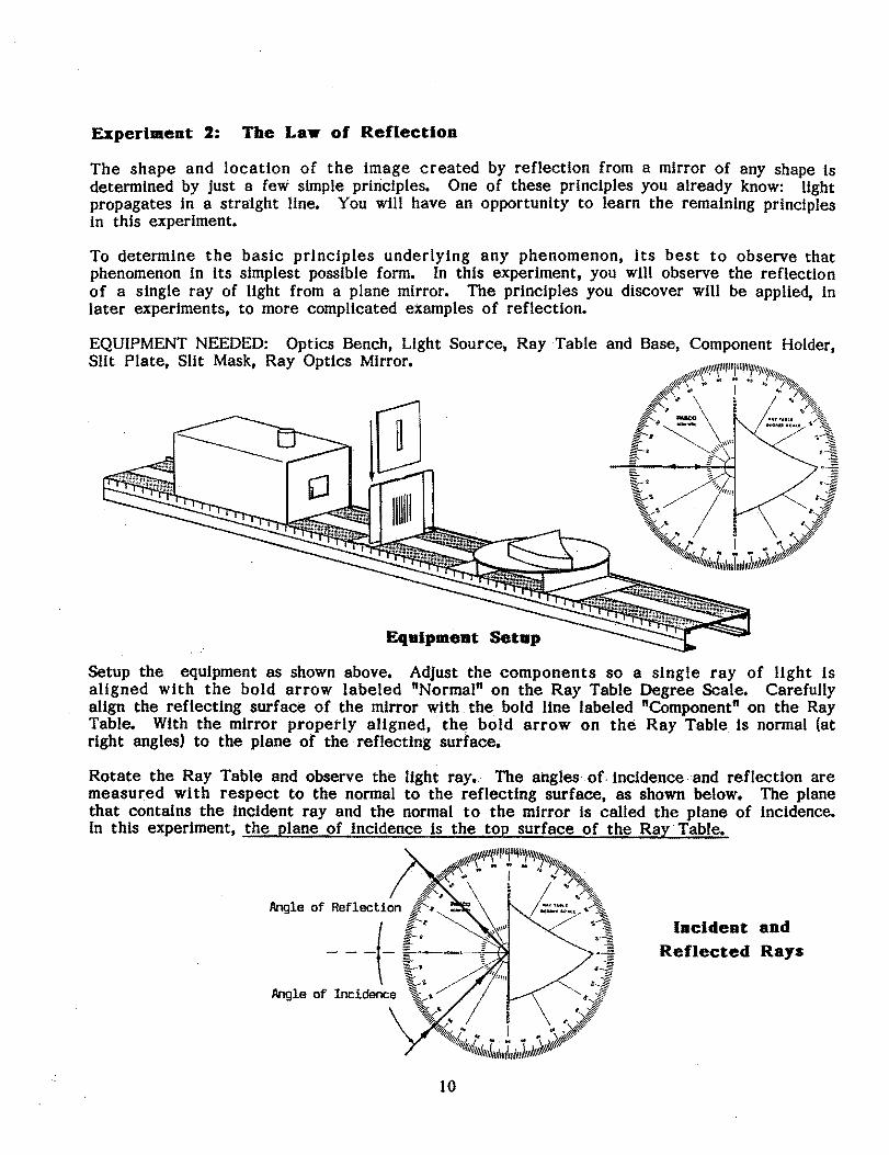
Experiment 2: The Law of Reflection
The shape and location of the image created by reflection from a mirror of any shape is determined by just a few simple principles. One of these principles you already know: Ught propagates In a straight Une. You will have an opportunity to learn the remaining principles in this experiment.
To determine the basic principles underlying any phenomenon, its best to observe that phenomenon In its simplest possible form. In this experiment, you will observe the reflection of a single ray of light from a plane mirror. The principles you discover will be applied, in later experiments, to more complicated examples of reflection.
EQUIPMENT NEEDED: Optics Bench, Light Source, Ray Table and Base, Component Holder, Slit Plate, Slit Mask, Ray Optics Mirror.
Eqalpment Setap
Setup the equipment as shown above. Adjust the components so a single ray of light is aligned with the bold arrow labeled "Normal" on the Ray Table Degree Scale. Carefully aUgn the reflecting surface of the mirror with the bold Unelabeled "Component" on the Ray Table. With the mirror properly aUgned, th~ bold arrow on the Ray Table. is normal (at right angles) to the plane of the reflecting surface.
Rotate the Ray Table and observe the Ught ray_ The angles of Incidence and reflection are measured with respect to the normal to the reflecting surface, as shown below. The plane that contains the InCident ray and the normal to the mirror is called the plane of incidence. In this experiment, the plane of incidence is the top surface of the Ray· Table.
Angle of Reflection Incident and
Reflected Rays---(
10

By rotating the Ray Table, set the angle of incidence to each of the settings shown in the table below. For each angle of incidence, record the angle of reflection (Reflection [1]). Repeat your measurements with the incident ray coming from the opposite side of the normal (Reflection (2]).
Angle of: Incidence Reflection [ 1 ] Reflection [21
0° 10° 20° 30° 40° 50° 60° 70° 80° 90°
1. Are the results for the two trials the same? If not, to what do you attribute the differences?
--------------------------------------~--------~----~------~------~.
2. What relationship holds between the angle of incidence and the angle of reflection?
3. Does the reflected ray always He in the plane of incidence?
ADDITIONAL QUESTIONS
1. The Law of Reflection has two parts. The first part relates the orientation of the reflected ray with respect to the plane of incidence. The second part relates the angle of reflection to the angle of incidence. State both parts of the Law of RefleCtion.
2. Physicists expend a great deal of energy in attempts to increase the accuracy with which an exact law can be proven valid. How might you test the Law of Reflection to a higher level of accuracy than in the experiment you just performed?
11

Experiment 3: Imale Formation In a Plane Mlrr.or
Looking into a mirror and seeing a nearly exact image of yourself hardly seems like the result of simple physical principles. But it is. The nature of the image you see in a mirror is understandable in tenns of the principles you have already learned: the Law of Reflection and the straight-line propagation of light.
In this experiment you will investigate how the apparent location of an image reflected from a plane mirror relates to the location of the object, and how this relationship is a direct result of the basic principles you have already studied.
EQUIPMENT NEEDED: Optics Bench, Light Source, Ray Table and Base, Component Holder, Slit PIa te, Ray Optics Mirror.
Equipment Setup
Setup the equipment. as shown above. Adjust the Slit Plate and Light Source positions for sharp, easily visible rays.
As shown, place a blank, white sheet of paper on top of the Ray Table, and place the Ray Optics Mirror on top of the paper. Position the mirror.sothat ~ alLof the light rays are reflected from its flat surface. Draw a line on the paper to mark the position of the flat· surface of the mirror.
Look into the mirror along the line of the reflected rays so that you can see the image of the Slit Plate and, through the silts, the filament of the Light Source.
1. Do the rays seem to follow a straight line into the mirror? _________
With a pencil, mark two points along one edge of each of the incident and reflected rays. Label the points (q,r2, etc.), so you know which points belong to which ray.
Remove the paper and reconstruct the rays as shown on the next page, using a pencil and straightedge. If you need to, tape on additional pieces of paper. Draw dotted lines to extend the incident and reflected rays. (If this ray tracing technique is unfamiliar to you, review ray tracing in Experiment 1: Introduction to Ray Optics.)
On your drawing, label the position of the filament and the apparent position of its reflected image.
12

2. What is the perpendicular distance from the filament to the plane of the mirror (d I as shown in the illustration below)?
Image of the Fil~t
_age Location in a. Plane Mirror
3. What is the perpendicular distance from the image of the filament to the phme of the mirror (d!)?
Change the pOSition of the mirror and the Light Source and repeat the experiment.
4. What is the relationship between object and image location for reflection in a plane mirror?
ADDITIONAL· QUESTIONS
1. If one wall of a room consists of a large. flat mirror, how much larger does the rQom appear to be than it actually is?
2. Make a diagram illustrating why an image of the letter F. reflected from a plane mirror. is inverted. (Treat each corner on the F as a source of light. Locate the image for each source to construct the image of the F.)
3. How does the size of the image reflected from a plane mirror relate to the size of the object?
13

ExperlmeDt 4: The Law of RefractioD
As you have seen, the direction of light propagation changes abruptly when Ught encounters a reflective surface. The direction also changes abruptly when llght passes from one medium of propagation into another. In this case, the change of direction is called Refraction.
As for reflection, a simple law characterizes the behavior of a refracted ray of light•. According to the Law of Refraction, also known as Snell's Law:
sin (angle of Incidence) = D sin (angle of refraction),
where D, called the index of refraction, is a constant for a given material. In this experiment you will test the validity of this law, and also measure the index of refraction
. for acrylic.
EQUIPMENT NEEDED: Optics Bench, Light Source, Ray Table and Base, Component Holder, Slit Plate, SUt Mask, Cylindrical Lens.
..........
--Angle ofl
Refraction
EqulpmeDt Setup
Setup the equipment as shown above. Adjust the component.ssoa single ray of Ught ..passes directly through the center of theRay Table Degree ,Scale.' Align the .. flat surface of .the Cylindrical Lens with the line labeled "Component". With the lens properly aligned, the radial lines extending from the center of the Degree Scale wi1l all be perpendicular to the circular surface of the lens.
Without disturbing the alignment of the Lens, rotate the Ray Table and observe the refracted ray for various angles of incidence.
1. Is the ray bent when it passes into the lens perpendicular to the flat surface of the lens?
. 2. Is the ray bent when it passes out of the lens perpendicular to the curved surface of the lens?
14

By rotating the Ray Table, set the angle of incidence to each of the settings shown In the' table below. For each angle of incidence, measure the angle of refraction (Refraction [1]). Repeat the measurement with the incident ray striking from the opposite side of the normal (Refraction [2]).
Angle of: Incidence Refraction [ 1 ] Refraction ( 2 J
00
100
200
300
400
500
600
700
800
900
4. Are your results for the two sets of measurements the same? If not, to what do you attribute the differences?
----------------------------------------------------------------------~.On a separate sheet of paper, construct a graph with sin (angle of refraction) on the x-axis and sin (angle of incidence) on the y-axis. Draw the best fit straight, line for each of your two sets of data.
5. Is your graph consistent with the Law of Refraction? Explain.
6. Measure the slope of your best fit lines. Take the average of your results to determine the Index of refraction for acryUc.
D = ______________________ ...;.
ADDITIONAL QUESTIONS
1. In performing the experiment, what difficulties did you encounter in measuring the angle of refraction for large angles of Incidence?
2. Was all the light of the ray refracted? Was some reflected? How might you have used the Law of Reflection to test the alignment of the Cylindrical Lens?
3. How does averaging the results of measurements taken with the Incident ray striking from either side of the normal improve the accuracy of the results?
15
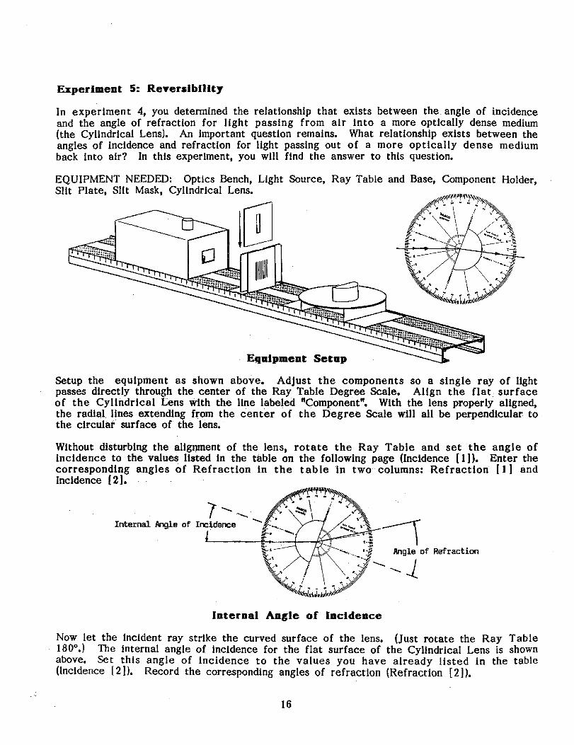
Eqalpment Setap
Experiment 5: Reyerslbillty
In experiment 4, you determined the relationship that exists between the. angle of incidence and the angle of refraction for light passing from air into a more optically dense medium (the Cylindrical Lens). An important question remains. What relationship exists between the angles of incidence and refraction for light passing out of a more optically dense medium back into air? In this experiment, you will find the answer to this question.
EQUIPMENT NEEDED: Optics Bench, Light Source, Ray Table and Base, Component Holder, Slit Plate, Slit Mask, Cyl1ndrical Lens.
Setup the equipment as shown above. Adjust the components so a single ray of light passes directly through the center of the Ray Table Degree Scale. AUgn the flat surface of the Cyllndrical Lens with the line labeled "Component". With the lens properly aligned, the radial Hnes extending from the center of the Degree Scale will all be perpendicular to the circulaf surface of the lens. .
Without disturbing the aUgt)l11ent of the lens, rotate the Ray Table and set the angle of incidence. to the values listed in the table on the following page (Incidence [1]). Enter the corresponding angles of Refraction in the table In two columns: Refraction [1] and Incidence [2].
.. ? "". Internal Angle of Incidence ....... \
Angle of Refraction
'-"J
Internal Anele of Incidence
180Now let the incident ray strike the curved surface of the lens. (just rotate the Ray Table
0 .) The internal angle of incidence for the flat surface of the Cylindrical Lens is shown
above. Set this angle of incidence to the values you have already listed In the table (InCidence [2 J). Record the corresponding angles of refraction (Refraction [2]).
16

Ra Incident on: Flat Surface Curved Surface An Ie of: Incidence 1 Refraction 1 Incidence 2 Refraction 2
00 100 20° 30°
400 500 600 700 800 900
For a light ray traveling from air into a more optically dense material, the index of refraction for the material is defined as:
o = sin (angle of incidence)/sin (angle of refraction).
For a light ray traveling from a more optically dense material back into air the index of refraction for the material is defined as: '
Or = sin (angle of refraction)/sin (angle of incidence).
1. Using your data froni'the table, what is the relationship between 0 and or?'
2. On a' separate sheet of paper,. make a diagram showing a light ray passing Into. and out of the CyUndrlcal'Lens. Show the correct angles':oflricldettce,;and;refraction at both surfaces traversed by the ray. Use arrow heads to indicate --the 'direction of propagation of the ray. Now reverse the arrows on the light ray. Show that the new angles of incidence and refraction are still consistent with the' Law of Refraction~ This is, the principle of optical reversiblllty.
3. Does the principle of optical reversibility hold for Reflection as well as Refrac.tion? Explain.
17

Experiment 6: Dispersion and Total Interaal Reflection
In this experiment you wlll look at two phenomena related to refraction: Dispersion and Total Internal Reflection. Dispersion introduces a complication to the Law of Refraction, which is that most materials have different Indexes of refractlonfor different colors of light. In Total Internal Reflection, it is found that in certain circumstances, light striking an Interface between two transparent media can not pass through the interface.
EQUIPMENT NEEDED: Optics Bench, Light Source, Ray Table and Base, Component Holder, Slit Plate, Slit Mask, Cylindrical Lens, Ray Table Component Holder, Viewing Screen.
J .........
.........Angle of .........
V,""ing Screen,\ Incidence
\
EqalpmeDt
Setup the equipment as shown above, so a single light ray is incident on the curved surface of the Cylindrical Lens.
DISPERSION
Set the. Ray Table so the angle of incidence of the ray striking the fhlt surface of the lens (from inside the lens) Is zero-degrees. Adjust the ·Ray,TableComponent Holder so the refracted ray is visible on the Viewing Screen.
Slowly increase the angle of incidence. As,youdo,watchtherefracted rayon the Viewing Screen.
1. At what angle of refraction do you begin to notice color separation in the refracted ray?
•
2. At what angle of refraction is the color separation a maximum?
3. What colors are present in the refracted ray? (Write them in the order of minimum to maximum angle of refraction.)
18
4. Measure the index of refraction of acrylic for red and blue light. (Remember, Dacrylic = sin (angle of incidence)/sin (angle of refraction) for light passing from air into acrylic. Here the ray is passing from acrylic into air. See Experiment 5: Reversibility.)
Dred =--------------
~Iue =------------....;;;
TOTAL INTERNAL REFLECTION
Without moving the Ray Table or the Cylindrical Lens, notice that not all of the light in the incident ray is refracted. Part of the light is also reflected.
1. From which surface of the lens does reflection primarily occur?
2. Is there a reflected ray for all angles of incidence? (Use the Viewing Screen to detect . faint rays.)
•
3. Are the angles for the reflected ray consistent with the Law of Reflection?
4. Is there a refracted ray for all angles of incidence?
5. How do the intensity of the reflected and refracted .raysvary wIth the angle of incidence?
6. At what angle of refraction Is all the light reflected (no refracted ray)?
19

Experiment 7: Converging Lens: Image and Object Relationships
Given a lens of any shape and index of refraction, you could determine the shape and location of the images it forms based only on the Law of Refraction. You need only apply the law along with some of the ray tracing techniques you have already used. However, for spherical lenses (and for spherical mirrors as weU), there is a more general equation that can be used to determIne the location and magnification of an image. This is the Fundamental Lens equation:
lido + 11dl = I/f,
where f is the focal length of the lens, and do and dl are the distance from the mirror to the image and object respectively (see the illustration below). The magnification of the image is given by the equation:
In this experiment, you will have an opportunity to test and apply these important equations.
NOTE: Instead of the above equation, you may have learned the Fundamental Lens Equation as SoSI = f2, where So and SI are the distances between the principle focus of the lens and the object and image, respectively. If so, notice that So = do - f, and SI = dl - f (see the illustration below). Using these equalities, convince yourself that lido + lIdl = I/f and SoSI = f2 are different expressions of the same relationship.
EQUIPMENT NEEDED: Optics Bench, Light Source, 75 mm Focal Length Convex Lens, Crossed Arrow Target, Component Holders (3). Viewing Screen.
L. So ..I. f --L..- f -oJ....-.-- Si .1, , , , , I" , do , ..,. , di ..,, , ,, I , I
II I
Crossed Arrow Target 75 nn Focal Length Convex Lens
Eqalpment Setap
Setup the equipment as shown above. Turn on the Light Source and slide the lens toward or away from the Crossed Arrow Target, as needed to focus the image of the Target onto the Viewing Screen.
I. Is the image magnified or reduced? _____________.....:.
2. Is the image inverted? ______________---"
3. Based on the Fundamental Lens Equation, what would happen to dl if you increased do even further?,
20

4. Using your answer to question 3, measure the focal length of the lens.
Focal Length =___~_____---.;:.
Now set do to the values (in millimeters) listed in the table below. At each setting, measure dj. Also measure hi, the height of the image. (ho is the height of the arrow on the crossed arrow target.)
DATA CALCULATIONS
do (mm) dl hI lIdj + lido lIf
500 450 400 350 300 250 200 150 100 75 50 .
Using the data you have collected, perform the calculations shown in the table.
5. Are your results in complete agreement with the Fundamental Lens Equation? If not, to what do you attribute the discrepancies?
•
6. For what values of do were you unable to focus an image onto the screen? Use the Fundamental Lens Equation to explain why.
ADDITIONAL QUESTIONS
1. For a lens of focal length f, what value of do would give an image with a magnification of one?
2. Is it possible to obtain a non-inverted image with a converging spherical lens? Explain.
3. For a converging lens of focal length f, where would you place the object to obtain an image as far away from the lens as possible? How large would the im,age be?
21