physics-astronomy-manuals.wwu.eduphysics-astronomy-manuals.wwu.edu/Janis Closed Cycle...
135
Transcript of physics-astronomy-manuals.wwu.eduphysics-astronomy-manuals.wwu.edu/Janis Closed Cycle...


PART 1: System Instructions


TABLE OF CONTENTS • I. Section 1
SAFETY:
1.1 Safety Summary
II. Section 2 INTRODUCTION:
2.1 General Description
2.2 System Components
2.3 System Configurations and Options
III. Section 3 INSTALLATION: 3.1 Mounting 3.2 Power Requirements 3.3 Compressor Cooling Requirements 3.4 Interconnections
IV. Section 4
• OPERATION: 4.1 Removing the Vacuum Shroud 4.2 Sample Mounting 4.3 Evacuation 4.4 Start-up Sequence/Cooldown 4.5 Temperature Control 4.6 Changing Samples 4.7 Shutdown
V. Section 5 MAINTENANCE: 5.1 Scheduled Maintenance 5.2 Unscheduled Maintenance 5.3 Maintenance Supplies
VI. Appendix Connector Wiring Diagrams Test Results Cryostat Engineering Drawing CTI Refrigerator & Components Manual •


•
SECTION 1
SAFETY
1.1 SUMMARY
All safety pressure reliefs are installed to provide protection to the equipment and operating personnel. Do not tamper with any pressure relief.
High voltage is present within the system components, and can cause serious injury from electric shock. Follow these instructions to ensure operator safety:
1. Disconnect all components from the electrical power source before making component interconnections.
2. Shut off the compressor power switch before connecting it to a power source.
3. Do not connect the cold head power cable to the cold head while the compressor is running.
High gas pressure is present within the system, and can cause serious injury if suddenly vented. Follow specified procedures when assembling and disassembling the self-sealing gas couplings on the flexible gas lines. Use caution to avoid puncturing the flexible gas lines.
•
•


SECTION 2
INTRODUCTION
2.1 GENERAL DESCRIPTION
Janis closed cycle refrigerator (CCR) systems provide a convenient means of cooling samples to temperatures below 10 K, and can be used to perform a wide variety of optical and electrical experiments between —8 K and 325 K (475 K optional). CCR systems require no liquid helium or liquid nitrogen as a source of cooling. Instead, a closed loop of helium gas is compressed and expanded, based on the Gifford-McMahon (G-M) thermodynamic cycle. During the expansion phase of each cycle, heat is removed from the cold finger, on which the sample is mounted. (A detailed description of the G-M cycle can be found on page C-3 in the refrigerator manual). A heater and thermometer are installed on the cold finger and are used to precisely control the sample temperature.
2.2 SYSTEM COMPONENTS
Janis CCR systems include the following components:
1. Compressor: This provides a supply of high-pressure helium gas to the cold head. It can be either air cooled or water cooled, and can be configured to match the available AC voltage and frequency.
2. Cold Head: This expands the helium gas to cool the sample. It includes two cold stations, the first stage (radiation shield mount) and the second stage (sample mount).
3. Gas Lines: These lines are connected between the compressor and cold head supply and return fittings, and transfer the helium gas between the two components. The gas lines are flexible stainless steel and include quick disconnect fittings on both ends.
4. Vacuum Jacket: This is bolted to the cold head. It includes an evacuation valve, safety pressure relief, electrical feedthroughs, and a clamped vacuum seal for easy access to the sample space.
5. Radiation Shield: This bolts to the cold head first stage. It is used to intercept room temperature radiation before it reaches the sample, allowing the lowest possible sample temperature to be achieved.
6. Optional Temperature Controller: This may be provided for use in monitoring and controlling the sample temperature. Detailed operating procedures can be found in the accompanying temperature controller manual.

2.3 JANIS CCR MODELS • Janis offers CCRs in a variety of configurations to match different experimental requirements. The supplied system configuration is indicated on the system manual data page. Standard configurations include:
CCS-150 A general purpose configuration that includes four optical windows and a 3" inner diameter vacuum jacket.
CCS-250 Intended for non-optical measurements, it includes a cylindrical stainless steel vacuum jacket.
CCS-350 This is compact optical configuration, suitable for use when available space is limited. It can be supplied in a rotatable (CCR-350R) or a non-optical (CCS-350T) configuration.
CCS-350S This sub-compact configuration is suitable for narrow gap magnets, or optical geometries with very limited space. A non-optical version (CCS-350ST) is also available.
A high temperature optical model with operating range from 12K - 475 K. A very high temperature (CCS-450H) version is also available with an operating range of up to 600 K.
CCS-450
•
•

•
SECTION 3
INSTALLATION
BEFORE BEGINNING THE SYSTEM INSTALLATION, REVIEW THE CTI COMPRESSOR AND COLD HEAD INSTRUCTIONS FOUND IN THE REFRIGERATOR MANUAL.
3.1 MOUNTING
The Janis CCR cold head can be mounted and operated in any convenient orientation. A mounting base with four 1/4" (M6) clearance holes is provided for mounting to a table or manipulator. Most systems include four tapped holes on the vacuum jacket bottom flange for mounting to an optical table with cold finger oriented downwards. The separate compressor assembly must remain upright to all times.
3.2 POWER REQUIREMENTS
The model 8200 compressor front panel includes switches used to select system voltage and frequency. Before connecting the compressor to any power source, be sure the switch configuration matches the available power source. (Refer to page 3-5 in the compressor manual for additional details).
Most temperature controllers also include selectable voltage settings. Choose the appropriate voltage by rotating the selection wheel located at the main power connector. Refer to the controller manual (if applicable) for additional information.
3.3 COMPRESSOR COOLING REQUIREMENTS
Model 8200 compressors are available in either air or water cooled configurations. Air cooled compressors must be located with free access to the front and rear panels, to avoid restriction of the air flow. Water cooled compressors require a continuous flow of cooling water for operation. (Refer to the compressor manual pages 3-3 through 3-5 for complete details).
•
•

• 3.4 SYSTEM INTERCONNECTIONS (SEE FIGURE 3.1)
Gas Lines - Interconnecting helium supply and return gas lines should be installed in the sequence described on page 3-1 of the compressor manual. Use two wrenches when tightening the fittings and support the gas lines to prevent gas leakage during assembly.
Cold Head Power - Connect the supplied cable from the compressor "cold head power" outlet to the matching connector on the cold head motor. Be sure the compressor power is off when making this connection.
Temperature Controller (when applicable) - Connect the supplied thermometry cable from the cold head 10-pin electrical feedthrough to the automatic temperature controller. The dual "banana plug" should be connected to the heater output and low terminals. (If no temperature controller is supplied with the system, a 10-pin mating connector is provided for attaching to a user supplied controller and cable).
•
•

•
• O Wz
O
0
c< O C C 7:t (cat
)0 -(
73 oo
1077 0
Z MC C
CV
3H
MO
O
O
77 m V/ 73
M C
70 00 man A an m
0
•


•
SECTION 4
OPERATION
4.1 REMOVING THE VACUUM SHROUD (SEE FIGURE 4.1)
1. Before removing the vacuum shroud, vent the vacuum space by turning the shroud evacuation valve knob counter-clockwise.
2. Remove the clamp located just above the evacuation valve, and carefully lift the shroud off the refrigerator.
3. Remove the four 6-32 screws that hold the radiation shield to the cold head, and lift the radiation shield off the refrigerator. The cold head sample mount and sample holder are now accessible.
4.2 SAMPLE MOUNTING
Most CCR systems are supplied with a sample holder. If the sample holder is removed, a thin film of thermal grease (such as Crycon) or thin indium foil should be used to enhance thermal contact when reinstalled. Grease or indium can also be used to improve the thermal contact between the sample and sample holder.
Janis CCR systems include provisions for additional electrical feedthroughs for customer wiring of the samples. Small gauge wires (32 AWG, 35 SWG) should be used to minimize heat leak into the sample, and the wires should be thermally anchored in several spots to the cold head using Stycast epoxy, GE 7031 varnish, by tying with nylon string or floss, or by using mylar or aluminum tape (See figure 4.2). Once the sample is mounted to the cold head, install the radiation shield and vacuum shroud. Any visible dirt or lint on the sealing gasket is sufficient to cause a vacuum leak, so be sure the gasket and flanges are clean and lightly greased before mounting the vacuum shroud.
•
•

VACUUM FLANGE ACUATION VALVE ERATOR KNOB
1/4-20 TAPPED MOUNTING HOLES
VACUUM SHROUD
,ZZ--
VACUUM FLANGE
RADIATION SHIELD
RADIATION SHIELD MOUNTING SCREWS
SAMPLE MOUNT
SAMPLE HOLDER
SYSTEM ACCESS FIGURE 4.1
S
•

TO SAMPLE THERMOMETER
SUGGESTED SAMPLE WIRING THERMAL ANCHOR LOCATION
TO CONTROL THERMOMETE AND HEATER
SAMPLE WIRING
• SYSTEM WIRING FIGURE 4.2
•

4.3 EVACUATION
Janis CCR systems are equipped with a bellows sealed evacuation valve, which allows evacuation and sealing of the insulating vacuum jacket. Prior to cooldown, connect a turbomolecular or diffusion pump to the valve and evacuate the shroud to a pressure of 1.0 x torr or less. Better vacuum levels provide greater insulation, resulting in shorter cooldown times and lower final temperatures. A cold-trapped mechanical vacuum pump can be used instead; however, this may limit the lowest temperature attainable.
The evacuation valve can remain open during the initial phase of the system cooldown. However, it should be closed before the sample temperature reaches 200 K to avoid backstreaming of oil from the vacuum pump into the cryostat. Outgassing and o-ring permeation will cause the pressure to rise slowly over time, therefore periodic re-evacuation may be necessary. Re-evacuation is required whenever a new sample is installed, or when the minimum temperature obtained begins to increase.
The CCS-450 high temperature model is equipped for operation to 475 K. When operating above 325 K, the system should be evacuated continuously to prevent contamination due to heater outgassing.
4.4 CRYOSTAT COOLDOWN
Switch on the automatic temperature controller and observe the temperature readings. Temperature values of —290 K to 300 K should be displayed.
Review Section 3 of the CTI compressor manual before beginning the cooldown. Establish a flow of cooling water as described in the CTI manual, then switch on the compressor. The temperature should begin to drop within a few seconds, and the system will achieve 10 K in about 1 hour.
Occasionally, time constraints will not permit thorough evacuation before the cooldown begins. In this case, water vapor and other condensables can freeze out and contaminate the sample. To avoid this problem, the cold finger can be kept at 300 K (using the automatic temperature controller) during the first 40 minutes of operation, which will cause the contaminants to settle on the cold radiation shield rather than on the sample. An additional 20 - 30 minutes will be needed for the sample to reach the base temperature. (This technique only needs to be used if initial system pressure is greater than 5 x 10⁻³ ton).
4.5 TEMPERATURE CONTROL
Most systems are supplied with an automatic temperature controller, silicon diode thermometer, and 25 ohm control heater. Options include other diode or resistance thermometers, thermocouples, and different heater resistance. The actual configuration of your system can be found on the data sheet contained in this manual.
Most Janis CCR models operate from <10 K to 325 K. (The CCS-450 operates from —12 K to 475 K). Choose a temperature setpoint from within the appropriate range, and enter values from Proportional (P), Integral (I), and Derivative (D) parameters. Some

•
•
experimentation may be required to optimize these settings for a particular application. In general, when operating at the lowest temperatures, (where the heat capacities are smallest), the (P) value should be low, and the (I) value should be high. Derivative (D) control can usually remain zero throughout the operating range. As the control temperature is increased, larger proportional and smaller integral values can improve temperature stability and response time.
Some controllers include an autotuning function that selects appropriate PID values automatically. This function is most useful only for temperatures above 50 K. For complete discussion of this feature, as well as comprehensive controller operating procedures and specifications, refer to the temperature controller manual.
4.6 CHANGING SAMPLES
Before changing samples, the cold head should be warmed to room temperature. This can be accomplished in either of two ways.
1) The refrigerator power can be turned off, and the system allowed to warm up for several hours. Use the control thermometer to determine when the system is approaching room temperature.
2) The refrigerator power can be turned off, and the temperature controller set for 295 K. Once the thermometer reaches 295 K, wait until the heater power approaches 0%. The evacuation valve can now be opened and the sample changed as described in sections 4.1 and 4.2. (Dry nitrogen or Argon gas can be used to break the vacuum if the sample is particularly sensitive to water vapor).
WARNING!
It is possible for the radiation shield to remain cold even after the sample has warmed to room temperature. Use gloves when handling a cold radiation shield to avoid low temperature burns.
4.7 SYSTEM SHUTDOWN
To shut down the system, simply turn off the compressor and temperature controller. If the interconnecting gas lines must be removed for any reason, allow the system to completely stabilize at room temperature before disconnecting.


SECTION 5
MAINTENANCE
5.1 SCHEDULED MAINTENANCE
The cold head and vacuum shroud assembly requires no regularly scheduled maintenance. The compressor adsorber should be replaced according to the schedule set forth in the CTI manual.
5.2 UNSCHEDULED MAINTENANCE
Unscheduled maintenance may occasionally be required to repair problems arising during the course of operation. These problems may be related to vacuum leaks, wiring failure, or refrigerator/compressor failure.
5.3 VACUUM LEAKS
Condensation on the outside of the vacuum jacket and inability of the sample mount to reach 10 K are indications of a vacuum problem. If these symptoms appear, re-evacuate the shroud as described in the evacuation paragraph above. If the symptoms disappear, no further action may be required. If the symptoms remain, or reappear quickly, a vacuum leak may be present. Contact Janis Research to obtain further direction in this case.
5.4 WIRING
Occasionally a heater or thermometer wire may be broken during sample removal or installation. If this occurs, reconnect the broken wire using 60/40 rosin core solder. Be sure to insulate the joint with shrinkable PVC tubing or Teflon insulation. The heater located at the sample mount is designed to accept the normal output of most temperature controllers. Occasionally, however, a heater may bum out. Replacement heater kits are available from Janis, and include all materials and instructions necessary for replacement.
5.5 REFRIGERATOR/COMPRESSOR FAILURE
Compressor and refrigerator failures are characterized either by an inability to operate, or by an increase in the minimum achievable temperature. In either case, refer to the troubleshooting section in the CTI operating manual for suggested corrective actions. If satisfactory operation is still not achieved, contact Janis Research for further recommendations.
•


PART 2: Wiring Diagrams


•
CRYOSTAT SERIAL NUMBER : 9199
10 PIN FEEDTHROUGH
LOCATION: INSTRUMENTATION SKIRT
PIN A - POS. CURRENT (I+)
PIN B - POS. VOLTAGE (V+) CALIBRATED TG-120-CU GaAIAs #10781
PIN C - NEG. CURRENT (I-) ON SAMPLE MOUNT (CONTROL SENSOR)
PIN D - NEG. VOLTAGE (V-)
PIN E -
PIN F -
PIN G -
PIN H -
PIN J - 25 OHM HEATER ON SAMPLE MOUNT
PIN K -
•
•


PART 3: System Drawing


PART 4: Test Results


S
CLOSED CYCLE REFRIGERATOR TEST SHEET
DATE:
3/18/05
LAB TECH : MD
REFRIGERATOR COMPRESSOR TEMPERATURE
CONTROLLER
MODEL NO. 8104001 8200 331s
SERIAL NO. a05289853 d04221868 333598
COMPRESSOR : NC
PUMPING TIME : 2 hours
COOLDOWN START TIM E : 10:40 am
COOLDOWN: TIME TEMP. K TEMP. V
ROOM T. 10:40 291.72k .909v 10 K 11:48 10.0k 4.13v ULTIMATE 13:12 8.26k 4.35v
TEMPERATURE CONTROL: SET POINT SET TIME STABLE TIME STABLE TEMP GAIN (P) RESET (I) HEATER POWER CONTROL SENSOR
20K 12:45 12:52 20.04K 1 72 HIGH 31% 20.0K 2.72V 150 K 1:00 1:25 150.0K 15 50 HIGH 50% 150.0K 1.273V 300 K 1:28 1:50 300.0K 40 20 HIGH 68% 300.0K .886V
•


PART 5:
Refrigerator & Compressor
Manual


CTI-CRYOGENICS HELIX TECHNOLOGY CORPORATION
Multiple Uses of Model 22C/350C Cryodyne® Refrigerators
Installation, Operation and Servicing Instructions
8040272 Rev. 100 (7/2002)
HELIX TECHNOLOGY CORPORATION www.helixtechnology.com

The information in this document is believed to be accurate and reliable. However, Helix Technology Corporation, cannot accept any financial or other responsibilities that may result from the use of this information. No warranties are granted or extended by this document.
• Helix Technology Corporation reserves the right to change any or all information contained herein without prior written notice. Revisions may be issued at the time of such changes and/or deletions.
Any duplication of this manual or any of its parts without expressed written permission from Helix Technology Corporation is strictly prohibited.
Any correspondence regarding this document should be forwarded to:
Helix Technology Corporation Mansfield Corporate Center Nine Hampshire Street Mansfield, Massachusetts 02048-9171 U.S.A.
Telephone: (508) 337-5000 FAX: (508) 337-5464
The following Helix Technology Corporation trademarks and service marks may appear in this document:
ConductronTM Convectron® Cryodyne® Cryogen®
Cryogenerator® Cryo-Torr® CTI-Cryogenics® FastRegenTM
GOLDLink® Granville-PhillipsTM GUTS® Helix Technology.. Your
Vacuum ConnectionsM
Helix® Micro-Ion® Mini-IonTM On-Board®
RetroEase® RetroFast® Stabil-1® Stabil-Ion®
ThinLineTM TurboPlus® Vacuum AssurancesM
•
All other trademarks or registered trademarks are the property of their respective holders.
Copyright© 2002 Helix Technology Corporation Printed in U.S.A. •

al-CRYOGENICS HELIX TECHNOLOGY CORPORATION
SAFETY CONSIDERATIONS
Your Cryodyne® Cryocooler has been engineered to provide extremely safe and dependable operation when properly used. Certain safety considerations need to be observed during the normal use of your cryocooter equipment. Warning blocks within the Manual text pinpoint these specific safety considerations. Warnings are defined as hazards or unsafe practices which could result in severe injury or loss of life.
AWARNING
HIGH VOLTAGE is present within the system and can cause severe injury from electric shock.
1. Disconnect the system from all power sources before making electrical connections be- tween system components and also before performing Troubleshooting and Maintenance procedures.
2. Ensure that all electrical power switches on the controllerlcompressor units are in the off position before connecting the compressor unit to its power source.
3. Never connect the cold-head power cable to the cold head while the compressor is running.
.10
HIGH GAS PRESSURE is present within the system and can cause severe injury from propelled particles or parts.
1. Do not modify or remove the pressure relief valves, either on the cold head or within the helium compressor.
2. Always depressurize the adsorber to atmospheric pressure before disposing of it.
3. Always bleed the helium charge down to atmospheric pressure before servicing or disassembling the self-sealing gas half-couplings.
BEFORE INSTALLING, OPERATING OR SERVICING EQUIPMENT, READ THIS MANUAL WHICH CONTAINS IMPORTANT SAFETY INFORMATION.
P/N 8040272 iii

CT1-CRYOGENICS HELIX TECHNOLOGY CORPORATION •
• iv P/N 8040272

CTI-CRYOGENICS HELIX TECHNOLOGY CORPORATION
Table of Contents
Section Title Page
Section 1- Introduction
1.1 General 1-1
1.2 Model 22/350C Cold Head 1-1
1.3 Specifications 1-1
Section 2 - Inspection and Installation
2.1 Inspection 2-1
2.2 Cold Head Installation 2-1
2.3 Connecting the Cryocoolers to the Compressor 2-2
Section 3 - Operation
3.1 Operating Log 3-1
3.2 Installing the Load 3-1
3.3 Start-up and Cooldown Procedures 3-1
3.4 Normal Operation 3-2
3.5 Shutdown Procedures 3-2
3.6 Storage 3-2
Section 4 - Functional Description
4.1 Model 22/350CP Cold Heads 4-1
Section 5 - Troubleshooting
5.1 Troubleshooting the Cold Head 5-1
5.2 Technical Inquiries 5-1
Section 6 - Unscheduled Maintenance
6.1 Maintenance Equipment 6-1
6.2 Adding Helium Gas 6-1
6.3 Helium Circuit Decontamination 6-1
6.4 Cold Head Decontamination Procedures 6-1
P/N 8040272

CTI-CRYOGENICS HELIX TECHNOLOGY CORPORATION
Section
Appendix A
Appendix B -
Appendix C
Appendix D
Appendix E -
Appendix F -
Appendix G
Appendix H
Table of Contents (continued)
Title
- Operating Log
Installation Tool Kit (Kit No. 8032040G016)
- Principles of Operation
- Conversion of Hydrogen-Vapor-Pressure Gauge Readings to Temperature
Establishing Gas Charge Pressure of Multi-Cryocooler Installations
Component Interconnection for Multiple Cryodyne Cryocoolers
- Model 22/350CP Cold Head Interface Drawings
- Customer Support Centers
Page
vi P/N 8040272

CTI-CRYOGENICS HELIX TECHNOLOGY CORPORATION
• Table of Contents (continued)
Figures
Section Title Page
1.1 The Model 22 Cold Head 1-2
1.2 The Model 350CP Cold Head 1-3
1.3 Typical Refrigeration Capacity of the Model 22C Cryodyne Cryocooler (60 Hz) 1-6
1.4 Typical Refrigeration Capacity of the Model 22C Cryodyne Cryocooler (50 Hz) 1-6
1.5 Typical Refrigeration Capacity of the Model 350C Cryodyne Cryocooler (60 Hz) 1-7
1.6 Typical Refrigeration Capacity of the Model 350C Cryodyne Cryocooler (50 Hz) 1-7
F.1 Multiple Cryocooler Installation with 8500 Compressor F-2
• Tables Section Title Page
1.1 Specifications for the Model 22C/350C Cryodyne Cryocooler 1-4
5.1 Cold Head Troubleshooting Procedures 5-2
A.1 Operating Log Sheet A-2
F.1 Equipment List for Multiple Cryocooler Usage F-3
Revision Status
Revision Page
Revised pg. 1-4 and G-2 according to DEO 10634 3/95 B
P/N 8040272 vii

CTI-CRYOGENICS HELIX TECHNOLOGY CORPORATION •
e
• VIII P/N 8040272

CTI-CRYOGENICS HELIX TECHNOLOGY CORPORATION
Section 1 Introduction
1.1 General
The Model 22G350C CryodyneCtryocooler provides reliable refrigeration at cryogenic temperatures for long, continuous periods. This cryocooler consists of multiple combinations of either the Model 22 and/or the Model 350CP Cold Heads.
For clarity purposes, due to the many variations of Model 22 and 350CP Cold Heads that can be combined with a compressor as a multiple cryocooler system, the cryocooler system will be identified throughout this manual as the 'Model 22C/350C Cryodyne Cryocooler".
The Model 22C/350C Cryodyne Cryocooler, which uses helium as the refrigerant, is designed to interface with many kinds of apparatus that require cryogenic temperatures. The use of a Cryodyne cryocooler as a source of cryogenic temperatures offers a degree of freedom in the design of such interfacing apparatus (in particular, size and operational flexibility) that is generally unobtainable when a liquid refrigerant is employed. One immediate advantage of a Cryodyne cryocooler is that the cold head can be operated in any orientation without loss of performance. After the end of an operating period of the cryocooler, the cold head cold stations can be raised to ambient temperature in a relatively short time.
This manual provides instructions for initial inspection and installation, operation, and servicing of the Model 22C/350C Cryodyne Cryocooler. Your cryocooler is highly-reliable and rugged unit that requires a minimum of servicing. Functional descriptions of the major assemblies that comprise the cryocooler are detailed in Section 4. Servicing instructions are covered in Sections 5 and 6. Section 5 covers troubleshooting in simplified tabular format. Section 6 presents unscheduled maintenance instructions; no scheduled maintenance is required for the cryocooler.
1.2 Model 22/350C Cold Heads Figures 1.1 and 1.2 show front and rear overall views
of the cold heads, with identification of the major external components.
1.3 Specifications Table 1.2 is a summary of specifications for the Model
220350C Cryodyne Cryocooler.
• P/N 8040272 1-1

CTI-CRYOGENICS HELIX TECHNOLOGY CORPORATION
S
Low J
O
1. Drive Unit 6. Gas Return Connector 2. Crankcase (Houses the Drive Mechanism) 7. Cylinder 3. Drive Motor 8. Second-Stage Cold Station 4. Power Connector 9. First-Stage Cold Station 5. Gas Supply Connector 10. Top Flange
•
Figure 1.1 The Model 22 Cold Head
1-2 PIN 8040272

HELIX TECHNOLOGY CORPORATION
II
O
O
dOIV7,1391tli3b 3611,00A7,0
O
O
12
8
CTI-CRYOGENICS
Legend 1. Cylinder 2. Second Stage Cold Station 3. Second Stage Cylinder 4. First Stage Cold Station 5. First Stage Cylinder 6. Top Flange 7. Helium Gas Supply Connector (with dust cap) 8. Helium Gas Return Connector (with dust cap) 9. Electrical Power Connector 10. Drive Motor 11. Crankcase (houses drive mechanism) 12. Pressure Relief Valve
• Figure 1.2 The Model 350CP Cold Head
P/N 8040272 1-3

al-CRYOGENICS HELIX TECHNOLOGY CORPORATION
Table 1.1 Specifications for the Model 22C/350C Cryodyne Cryocooler
Cold Head
Dimensions (approximate):
COLD HEAD LENGTH IN.(MM)
WIDTH IN.(MM)
HEIGHT IN.(MM)
Model 22 9.1 (231) 6 (152) 11.25 (286)
Model 350CP 11.9 (302) 6 (152) 18.50 (470)
Weight (approximate):
COLD HEAD LBS. KG
Model 22 14 6.5
Model 350CP 33 15.0
Power requirement
Ambient-temperature operating range
Interface Data: Gas-supply connector Gas-return connector
Orientation
Supplied from the compressor
60°F to 100°F (16°C to 38°C)
1/2-inch self-sealing coupling 1/2-inch self-sealing coupling
The cold heads may be operated in any orientation.
Refrigeration Capacity: Figures 1.3 and 1.4 are graphs showing typical refrigeration capacity of a Model 22C Cryodyne Cryocooler (at 60 Hz and 50
Hz respectively). The graphs in Figures 1.5 and 1.6 show typical refrigeration capacity of Model 350C Cryodyne Cryocooler at 60 Hz and 50 Hz.
1-4 P/N 8040272

CTI-CRYOGENICS HELIX TECHNOLOGY CORPORATION
Table 1.1 Specifications for the Model 22C/350C Cryodyne Cryocooler (Cont.)
Cold Head (Cont.)
The refrigeration capacities depicted in the above figures (Figures 1.3 through 1.6) represent typical performance from a multiple cryocooler system utilizing the full capabilities of the 8500 Compressor. Refrigeration capacities will increase for cryocooler systems which use less than full compressor output.
Temperature stability under constant load: ± 1.0K (At the second-stage cold station)
No-load cooldown time to 20K:
Model 22C 25 minutes; 60 Hz power 30 minutes; 50 Hz power
Model 350C 40 minutes; 60 Hz power 50 minutes; 50 Hz power
P/N 8040272 1-5

al-CRYOGENICS HELIX TECHNOLOGY CORPORATION
30
28
26
24
'' 22 a: W 20
W '4 is ,.., O z 16 0 w''' 4° 14
12
10
8
30 35 40 45 50 55 60 65 70 75 BO 85 90 95 100 FIRST STAGE TEMP. ( K1
Figure 1.3 Typical refrigeration capacity of the Model 22C cryodyne cryocooler (60 Hz)
sum.
•& 24 a: 3 22
W li 20 4/S
z O .4".
16
35 40 45 50 55 60 65 70 75 BO 85 90 95 100 105 110 FIRST STAGE TEMP.110
Figure 1.4 Typical refrigeration capacity of the Model 22C cryodyne cryocooler (50 Hz)
1-6 P/N 8040272

34
32 20
14 15
1 I I 1 i 1 I I 1 I I 12 6
FIRST STAGE HEAT LOAD 1 WATTS 1
SECOND STAGE HEAT LOAD (WATTS)
4
30
28
26
ksJ 24
N 22 0 8 20
18
6
0- 25
16 20
10
I I 1 1 1 1 I I 12 —
0 I
al-CRYOGENICS HELIX TECHNOLOGY CORPORATION
30
28
26
24
122
120
0 18 O
ta., 16
14
12
10
30 35 40 45 50 55 60 65 70 75 80 85 90 95 100
FIRST STAGE TEMP. (XI
Figure 1.5 Typical refrigeration capacity of the Model 350C cryodyne cryocooler (60 Hz)
40 45 50 55 60 65 70 75 BO 85 90 95 100 105 110 FIRST STAGE TEMP.IK1
Figure 1.6 Typical refrigeration capacity of the Model 350C cryodyne cryocooler (50 Hz)
P/N 8040272 1-7

CTI-CRYOGENICS HELIX TECHNOLOGY CORPORATION
•
•
• 1-8 P/N 8040272

CTI-CRYOGENICS HELIX TECHNOLOGY CORPORATION
Section 2 Inspection and Installation
2.1 Inspection
Upon receipt, inspect the Model 22C/350C Cryodyne Cryocooler for evidence of damage as described below.
Report damage to the shipper at once.
Retain shipping cartons for storage or return shipment.
Inspect the exterior of each cold head for evidence of damage. Examples of such evidence are a bent cold station and a dented cylinder.
2.2 Cold Head Installation Proceed as follows to install each cold head in your
vacuum system. Refer to Appendix K, for the major interface dimensions of the Model 22/350CP Cold Heads.
1. Using a clean, lint-free cloth moistened with solvent such as acetone, carefully clean the groove for the 0-ring in the mounting flange of your vacuum system.
2. Using a clean, dry cloth, sparingly lubricate the 0-ring with low-vapor-pressure grease; for example, Apiezon "L" grease. Do not clean the 0-ring with solvent.
3. Install the 0-ring in the 0-ring groove.
4. Carefully install the cold head on the mounting flange of your vacuum chamber.
Each cold head and related components must have adequate vacuum integrity for proper operation in your vacuum system. Inadequate vacuum will result in an unwanted gas conduction heat load from the room temperature vacuum housing to the cold surfaces of the cold head cold stations. A small vacuum leak will cause high-than-normal cold station operating temperatures, combined with a gradual temperature increase; a large vacuum leak may prevent satisfactory cooldown. The rough-pumping system should be isolated from your vacuum system, once cooldown has started, by closing the roughing valve.
It is recommended that a suitable pressure relief valve be installed in your vacuum system to prevent any possible positive pressure rise during warm-up.
P/N 8040272 2-1

If the indicated pressure is lower than the specified value, add helium gas as described in Section 6.2.
6. The last step required for installation is making electrical connections:
lir AWARNING
The system power switch on the compressor must be in the OFF position before making any and all electrical connections.
a. Connect the cold head power cable(s) to the rear panel of the compressor and the other end to the electrical power connection on each cold head.
b. Plug the compressor input power cable into the power source.
al-CRYOGENICS HELIX TECHNOLOGY CORPORATION
2.3 Connecting the Cryocoolers to the Compressor
A component interconnection diagram for a multiple cryocooler installation is shown in Appendix I. Refer also to Figures 1.1, 1.2 and 1.3 for the location of components discussed below.
IS AWARNING Do not connect the compressor to its power source
until all connections have been made between the components of the cryocooler.
Make the connections between the cryocoolers and compressor:
If the indicated pressure is higher than what is specified in your compressor manual, reduce the pressure as follows:
a. Remove the flare cap from the gas charge fitting located on the rear of the compressor.
b. Open the gas charge valve very slowly. Allow a slight amount of helium gas to escape until the helium pressure gauge reads the value indicated in your compressor manual.
c. Close the gas charge valve and reinstall the flare cap.
•
1. Remove all dust plugs and caps from the supply and return lines, compressor, and cold heads. Check all fittings.
2. Install all helium tees to the compressor or cold heads.
3. Connect the helium return line from the gas-return connector on the rear of the compressor to the gas-return connector on the cold head.
4. Connect the helium supply line from the gas-supply connector on the rear of the compressor to the gas-supply connector on the cold head.
5. Verify proper helium supply static pressure by confirming that the helium pressure gauge reading and ambient temperature range are as specified in the Model for the CTI compressor being used.
This static pressure applies to a typical multiple cryocooler installation using 10-foot interconnecting lines. If your installation has longer interconnecting lines, then contact the Product Service Department for assistance in calculating the static pressure.
•
• 2-2 P/N 8040272

al-CRYOGENICS HELIX TECHNOLOGY CORPORATION
Section 3 Operation
Do not begin the Model 22C/350C Cryodyne Cryocooler operation until all steps in the inspection and installation procedures have been completed and confirmed.
3.1 Operating Log It is highly advisable to create and maintain a detailed
operating log. The record will assist in troubleshooting should problems arise. Appendix A contains a sample operating log for your use. You may wish to make photocopies of this sample log.
3.2 Installing the Load The load can be either attached directly to the cold
station concerned or coupled to it with heat wicks (braided copper straps). Indium foil that is 0.002 to 0.005 inch thick should be used between the mating surfaces to improve thermal conduction.
When the installation of the load has been completed, rough-pump your vacuum chamber down to 5 x 10⁻² torr or better. Then close the roughing valve prior to starting the cooldown of the cryocooler. Upon cooldown, the refrigerator will cryopump residual gases in the chamber and an insulating vacuum between 10-4 and 105 torr will be achieved.
3.3 Start-up and Cooldown Procedures
1. Ensure the roughing valve is closed.
2. Turn on the system power ON/OFF switch to operate the compressor and cold heads. Record helium pressure and temperature reading during the initial cooldown.
3. During cooldown, record the operating log data at 15-minute intervals. To ensure minimum cooldown time, do not apply electrical power to any load during the cooldown.
The cooldown time associated with a normal cooldown with no load attached to the second-stage cold head is specified in Table 1.1. The cooldown time will increase approximately 15 minutes for each pound-of-mass increase of the attached load.
Pressure regulation during a cooldown is automatic. The compressor will vary during cooldown but will usually attain steady values nominally within 45 minutes after cooldown.
P/N 8040272 3-1

CTI-CRYOGENICS HELIX TECHNOLOGY CORPORATION
3.4 Normal Operation
The components of the cryodyne cryocooler are designed to operate without operator assistance. During the first 100 hours of operation a slight drop in compressor pump oil level may occur, but a drop is of no concern as long as the oil level is visible. If oil level is not visible, contact the Product Service Department.
The helium return pressure gauge should be checked once a week and the reading noted in the operating log. If the gauge reading falls outside the satisfactory operating range as specified in your compressor manual, refer to Section 5, Troubleshooting Procedures.
CAUTION Never exceed operating compressor return pressure
higher than the value specified for your compressor. Compressor damage can occur.
3.5 Shutdown Procedures 1. Close the Hi-Vac valve between the cold head and
its vacuum chamber.
2. Turn off the system power ON/OFF switch on the compressor to shut down the compressor and cold heads. If you desire to individually shut down a cold head, a remote switching circuit should be installed. Contact the Product Service Department for assistance.
3. It will take many hours to warm the cold head cylinder to ambient temperature with no heat load present. If a rapid warm-up is desired, break the vacuum with a clean, dry gas, such as nitrogen or argon. If this method is used, leave the valve open to allow the expanding gas to escape as the cylinder warms.
3.6 Storage
The cryocooler is fully protected during storage if kept under positive helium pressure and all components left connected. Periodically check the helium return pressure gauge on the compressor. If the gauge reads below the specified value in your compressor manual, add helium as described in Section 6.2.
If the cold head is removed from your vacuum system, be careful not to damage the cold head cylinder and sealing surfaces.
3-2 P/N 8040272

CTI-CRYOGENICS HELIX TECHNOLOGY CORPORATION
Section 4 Functional Description
This Section presents additional detail description of each cold head and the compressor. Knowledge of the content of this Section is not required in order to operate your cryocooler. The information is included in this Manual for the benefit of those readers who desire a more comprehensive understanding of the functional operation of the Cryodyne cryocooler.
4.1 Model 22/350CP Cold Heads (see Figures 1.1 and 1.2)
The function of each cold head is to produce continuous closed-cycle refrigeration at temperatures that, depending upon the heat load imposed, are in the range of 40K to 100K for the first-stage cold station and in the range of 10K to 20K for the second-stage cold station.
The cold head has three major components: the drive unit; the cylinder; and the displacer-regenerator assembly, which is located inside the cylinder.
The drive unit consists of the following subassemblies: the drive motor; the crankcase; and the drive mechanism, which is located inside the crankcase. The drive unit actuates the displacer-regenerator assembly and controls the flow of helium into and out of the cold head.
The motor employed is a direct-drive, constant-speed motor that operates at the following speeds for 50 or 60 Hz power applications.
COLD HEAD FREQUENCY
(HZ) MOTOR RPM
Model 22 50 167 60 200
Model 350CP 50 60 60 72
Each motor housing has two connectors: one is the electrical power connector, through which power is supplied; the other is the helium-gas return connector.
Functionally, the incoming high-pressure helium gas from the compressor enters the cold head through the helium-gas supply connector. The gas then passes into the displacer-regenerator assembly, flows out through the displacer-regenerator assembly, into the crankcase, through the motor housing, and finally through the helium-gas return connector to the compressor. The helium gas expansion in the displacer-regenerator assembly provides cooling at the first and second-stage cold stations, each at different temperatures.
Refer to Appendix C for a detailed explanation on the principles of operation.
P/N 8040272 4-1

CTI-CRYOGENICS HELIX TECHNOLOGY CORPORATION •
•
• 4-2 P/N 8040272

CTI-CRYOGENICS HELIX TECHNOLOGY CORPORATION
• Section 5 Troubleshooting
5.1 Troubleshooting the Cold Head
Most of the problems in the troubleshooting tables are followed by several possible causes and corrective actions. The causes and corresponding actions are listed in their order or probability of occurrence. 1) is most likely, 2) is next most likely, etc.
Maintaining a log of the readings (see Appendix A, Figure A.1) of the temperature indicator during normal operation is a valuable tool in troubleshooting the cold head. Values higher than 20K indicate that the second-stage cold station is too warm. A temperature below 20K means the cold head is cold enough for operation.
5.2 Technical Inquiries Please refer to page ii of this manual for a complete
list of the CTI-CRYOGENICS' world wide customer support centers.
P/N 840272 5-1

CTI-CRYOGENICS HELIX TECHNOLOGY CORPORATION
Table 5.1 Cold Head Troubleshooting Procedures
Problem Possible Cause
Corrective Action
• 1) The cold head fails to cool
down to the required operating temperature, or takes too long to reach that temperature.
1) Low system charge pressure in the compressor.
2) Vacuum leak in your vacuum system.
3) Excessive heat load.
4) Contamination of the helium gas.
1) Refer to Adding Helium Gas, Section 6.2.
2) Check your vacuum system for leaks.
3) Eliminate excessive heat load.
4) Refer to Decontamination Procedures, Section 6.2.
2) The cold head drive unit fails 1) Lack of power from the 1) a. Ensure that the system power to run, even though the com- compressor. ON/OFF switch on the pressor is operating. compressor is on.
b. Ensure that the cold head power is properly attached to the electrical power connector of the cold head drive unit.
c. Contact the Product Service Department for assistance.
2) An internal malfunction in compressor.
2) Contact the Product Service Department for assistance.
•
•
3) The cold head drive unit operates erratically, usually accompanied by considerable noise.
1) Contamination of the helium gas.
2) Internal malfunction of the cold head.
1) Decontaminate per Section 6.2.
2) Contact the Product Service Department for assistance.
5-2 P/N 840272

0-I-CRYOGENICS HELIX TECHNOLOGY CORPORATION
Section 6 Unscheduled Maintenance
Two types of unscheduled maintenance may be required from time to time. These are 1) the addition of helium gas to the cryodyne cryocooler, and 2) helium circuit decontamination.
6.1 Maintenance Equipment Your CTI-CRYOGENICS compressor is supplied
with appropriate maintenance equipment and disposable supplies for servicing this unit. In addition, you should have a Maintenance Tool Kit, P/N 8140000K001, that provides wrenches, etc. for connecting self-sealing Aeroquip couplings between the cold head(s) and the compressor. The specific contents of this kit are listed in Appendix B.
6.2 Adding Helium Gas Refer to the Maintenance section of the manual for
your CTI-CRYOGENICS compressor for detailed instructions on adding helium gas to your cryodyne cryocooler.
6.3 Helium Circuit Decontamination
Contamination of the helium-gas circuit is indicated by sluggish or intermittent operation (ratchetting) of the cold head drive mechanism. With severe contamination the cold head drive may seize and fail to operate. One of the major sources of contamination is using helium gas of less than the required purity. When performing the decontamination process, use only 99.999% pure helium gas, and the regulator and charging line must be properly connected and purged.
This decontamination procedure will remove contaminants from the cold head and/or compressor thereby restoring performance. The coldtrapping of contaminants inside the cold head during this procedure will also decontaminate the compressor if the contamination of the system is not severe. Separate decontamination of the compressor is required whenever the compressor has been opened to atmosphere, or the pressure has dropped to zero.
6.4 Cold Head Decontamination Procedures
1. Cool down the cold head and operate it for one to three hours. If the system will not cool down, proceed to step 2. Operating the cold head will isolate the contaminants by "freezing" them in the cold head. The contaminants in the helium gas circuit of the refrigerator tend to become frozen inside the cold head. The longer the cold head is operated beyond the one-hour period, the greater is the amount of contamination that becomes isolated inside the cold head.
2. Shut down the cold head per Section 3.5.
3. Immediately disconnect the helium supply and return lines from the gas-supply and gas-return connectors located at the rear of the compressor. Leave them attached to the cold head.
4. Attach the maintenance manifold to the disconnected ends of the helium return and supply lines.
P/N 8040272 6-1

CTI-CRYOGENICS HELIX TECHNOLOGY CORPORATION
5. Reduce the pressure in the cold head to a level of 30 psig by using the maintenance manifold. Reducing the pressure in the cold head below 30 psig (200 kPa) may introduce more contaminants into the helium circuit.
6. Allow the second-stage of the cold head to warm up to room temperature. The warm-up time can be decreased by backfilling the vacuum chamber to one atmosphere with dry argon or nitrogen gas. Using the gas heater, Cll P/N 8080250K020, will reduce the warm-up time about 50 percent, and will maintain the gas temperature below 150°F (66°C) limit.
7. Once the cold head has reached room temperature, attach a two-stage regulator (0-3000/0-400 psig) and charging line to a helium bottle (99.999% pure). DO NOT OPEN THE BOTTLE VALVE AT THIS TIME. Purge the regulator and charging line as instructed in steps a through d below. Do not use helium gas that is less than 99.999% pure.
a. Open the regulator a small amount by turning the adjusting knob clockwise until it contacts the diaphragm, then turn approximately 1/8 to 1/4 turn more, so that the regulator is barely open.
b. Slowly open the bottle valve, and purge the regulator and line for 10 to 15 seconds. Turn the regulator knob counterclockwise until the helium stops flowing.
c. Loosely connect the charge line to the 1/8-inch Hoke valve on the maintenance manifold.
d. Purge the charge line again, as in step a, for 30 seconds, and tighten the charge line flare fitting onto the Hoke valve while the helium is flowing.
This procedure is required to ensure that both the regulator and the charging line will be purged of air and that the air trapped in the regulator will not diffuse back into the helium bottle. For best results, CTI suggests a dedicated helium bottle, regulator, and line, which are never separated, for adding helium.
8. Perform in sequence:
a. Backfill the cold head with helium to a static charge pressure of 200-205 psig (1380-1415 kPa) by adjusting the regulator to the required pressure, and opening the Hoke valve on the manifold. Close the Hoke valve when the pressure is correct.
b. Depressurize the cold head to 30 and 50 psig (200 and 330 kPa) by slowly opening the ball valve and allowing the helium to bleed out slowly. Do not reduce the pressure to less than 30 psig or the cold head may be further con-taminated.
c. Perform the flushing steps a and b four times.
d. Pressurize the cold head to the static charge pressure specified in your compressor manual and run the cold head drive motor for 10 to 30 seconds by actuating the cold head ON/OFF switch to on.
e. Perform steps b through d four times for a total of 25 flushes and a total of 5 drive-motor runs.
9. Verify that the cold is pressurized to the same static charge pressure as determined in step 8d above.
10. Disconnect the maintenance manifold from the helium return and supply lines.
11. Reconnect the helium return and supply lines to the return and supply connectors located at the rear of the compressor. The cold head is now ready for operation.
6-2 P/N 8040272

al-CRYOGENICS HELIX TECHNOLOGY CORPORATION
Appendix A
Operating Log
The operating log sheet included as Table A.1 in this Appendix should be reproduced for your use with the Model 22C/350C Cryodyne Cryocooler. It is important to maintain an operating log, especially when operating the cryocooler for the first time or in a new installation. Readings of the compressor pressure gauge and the vacuum chamber should be recorded during cooldown, and also while the cryocooler is operating under normal load conditions. (Readings of the cold station temperature, as well as the cooldown time from ambient temperature to 20K, should also be recorded, if a means for obtaining such data is available.)
These records may be extremely useful later, both in recognizing degradation of performance and in troubleshooting. During start-up and cooldown, data should be recorded at 10-minute intervals. During normal operation, these data should be recorded daily.
P/N 8040272 A-1

al-CRYOGENICS HELIX TECHNOLOGY CORPORATION
A-2 P/N 8040272

CTI-CRYOGENICS HELIX TECHNOLOGY CORPORATION
• Appendix B Installation Tool Kit
(Kit No. 8032040G016)
ITEM NUMBER QUANTITY DESCRIPTION
1 1 1 inch open-end wrench, Armstrong, for self-sealing coupling
2 1 1 1/8-inch open-end wrench, Armstrong, for self-sealing coupling
3 1 1 3/16-inch open-end wrench, Armstrong, for self-sealing coupling
4 1 Depressurization Fitting, 1/2 inch
410
• P/N 8040272 B-1

al-CRYOGENICS HELIX TECHNOLOGY CORPORATION
B-2 P/N 8040272

GI-CRYOGENICS HELIX TECHNOLOGY CORPORATION
• Appendix C Principles of Operation
The following Technical Data sheet explains the compressor employed in the Cryodyne cryocooler
principles of operation by which the cold head and achieve cryogenic levels of refrigeration.
•
P/N 8040272 C-1

CTI-CRYOGENICS HELIX TECHNOLOGY CORPORATION
TECHNICAL DATA CRYODYNE® CLOSED CYCLE HELIUM REFRIGERATORS
•
The cooling process (cycle) of CRYODYNE Helium Refrigerators is analogous to that of common household refrigerators. In the latter, a working fluid (freon gas) is compressed, the heat of com-pression removed by air-cooled heat exchangers, and the gas is then expanded to produce cooling below the ambient temperature. This simple compression-expansion process will suffice for the house-hold refrigerator, where tempera-tures in the sub-zero fahrenheit range are required. However, CRYODYNE systems must operate effectively and routinely at temp-eratures down to 6K (-449°F). Attainment of such extreme low levels requires highly efficient heat exchangers, and the use of a working fluid (helium gas) that re-mains fluid at temperatures ap-proaching absolute zero (-459.6°F, -273.1°C, OK).
All CRYODYNE systems com-prise an air-cooled or water-cooled, oil-lubricated compressor unit with oil separation system (carry-over oil vapors would solidify at cry-ogenic temperatures and plug the heat exchangers of the refrigera-tor); and a refrigerator unit (re-motely located from the com-pressor), which operates at slow speeds, has ample clearances, and
Figure I Elementary Cooling Circuit
has room-temperature valves and seals.
The flow of helium in the refrig-erator is cyclic. The sequence of operations can be illustrated by a single cylinder and piston (Figure 1).
A source of compressed gas is connected to the bottom of cylin-der C through inlet valve A. Valve B is in the exhaust line leading to the low-pressure side of the com-pressor. With the piston at the bot-tom of the cylinder, and with valve B (exhaust) closed and valve A (in-let) open, the piston is caused to move upward and the cylinder fills with compressed gas. When valve A is closed and valve B is opened, the gas expands into the low-pressure discharge line and cools. The resulting temperature gradient across the cylinder wall causes heat to flow from the load into the
cylinder. As a result, the gas warms to its original temperature. With valve B opened, and valve A closed, the piston is then lowered, displacing the remaining gas into the exhaust line, and the cycle is completed.
This elementary system, while workable, would not produce the extreme low temperatures required for uses to which the CRYODYNE refrigerators are applied. Thus the
Figure 2 Cooling Circuit with Regenerator
incoming gas must be cooled with the exhaust gas before the former reaches the cylinder. This is ac-complished in the CRYODYNE refrigerator by a regenerator, which extracts heat from the in-coming gas, stores it, and then releases it to the exhaust stream (Figure 2).
•
• C-2 P/N 8040272
CTI-CRYOGENICS HELIX TECHNOLOGY CORPORATION
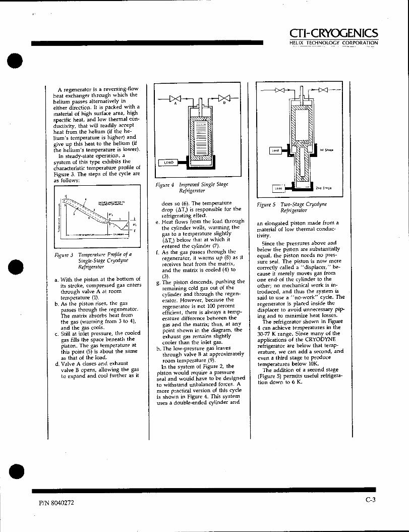
A regenerator is a reversing-flow heat exchanger through which the helium passes alternatively in either direction. It is packed with a material of high surface area, high specific heat, and low thermal con-ductivity, that will readily accept heat from the helium (if the he-lium's temperature is higher) and give up this heat to the helium (if the helium's temperature is lower).
In steady-state operation, a system of this type exhibits the characteristic temperature profile of Figure 3. The steps of the cycle are as follows:
Figure 3 Temperature Profile of a Single-Stage Cryodyne Refrigerator
a. With the piston at the bottom of its stroke, compressed gas enters through valve A at room temperature (1).
b. As the piston rises, the gas passes through the regenerator. The matrix absorbs heat from the gas (warming from 3 to 4), and the gas cools.
c. Still at inlet pressure, the cooled gas fills the space beneath the piston. The gas temperature at this point (5) is about the same as that of the load.
d. Valve A closes and exhaust valve B opens, allowing the gas to expand and cool further as it
Figure 4 Improved Single Stage Refrigerator
does so (6). The temperature drop (ST,) is responsible for the refrigerating effect.
e. Heat flows from the load through the cylinder walls, warming the gas to a temperature slightly (ST,) below that at which it entered the cylinder (7).
f. As the gas passes through the regenerator, it warms up (8) as it receives heat from the matrix, and the matrix is cooled (4) to (3).
g. The piston descends, pushing the remaining cold gas out of the cylinder and through the regen-erator. However, because the regenerator is not 100 percent efficient, there is always a temp-erature difference between the gas and the matrix; thus, at any point shown in the diagram, the exhaust gas remains slightly cooler than the inlet gas.
h. The low-pressure gas leaves through valve B at approximately room temperature (9). In the system of Figure 2, the
piston would require a pressure seal and would have to be designed to withstand unbalanced forces. A more practical version of this cycle is shown in Figure 4. This system uses a double-ended cylinder and
Figure 5 Two-Stage Cryodyne Refrigerator
an elongated piston made from a material of low thermal conduc-tivity.
Since the pressures above and below the piston are substantially equal, the piston needs no pres-sure seal. The piston is now more correctly called a "displacer," be-cause it merely moves gas from one end- of the cylinder to the other; no mechanical work is in-troduced, and thus the system is said to use a "no-work" cycle. The regenerator is placed inside the displacer to avoid unnecessary pip-ing and to minimize heat losses.
The refrigerator shown in Figure 4 can achieve temperatures in the 30-77 K range. Since many of the applications of the CRYODYNE refrigerator are below that temp-erature, we can add a second, and even a third stage to produce temperatures below 10K.
The addition of a second stage (Figure 5) permits useful refrigera-tion down to 6 K.
P/N 8040272 C-3

al-CRYOGENICS HELIX TECHNOLOGY CORPORATION •
•
C-4 P/N 8040272

al-CRYOGENICS HELIX TECHNOLOGY CORPORATION
• Appendix D Conversion of Hydrogen-Vapor-Pressure
Gauge Readings to Temperature
Use the data given below to convert a reading of the The hydrogen-vapor-pressure gauge should not be
hydrogen-vapor-pressure gauge (in psia) to the tempera- used to measure temperatures higher than 26K. ture of the second-stage cold station (in degrees Kelvin).
TEMPERATURE VS. HYDROGEN-VAPOR PRESSURE
26
24
22
20
K 18
16
14
12 —
10 1 I 1 1 1 1 1 i 1 1 1 1 1 1 1
0 4 8 12 16 20 24 28 32 36 40 44 48 52 56 60
PSIA
PSIA K PSIA K
0 Less than 12 15 20.5 1 13.9 18 21.1 2 15.2 21 21.7 3 16.0 24 22.2 4 16.7 27 22.6 5 17.2 30 23.1 6 17.7 35 23.7 7 18..1 40 24.3 8 18.5 45 24.8 10 19.2 50 25.3 12 19.7 55 25.8 •
P/N 8040272 D-1

CTI-CRYOGENICS HELIX TECHNOLOGY CORPORATION
D-2 P/N 8040272

CTI-CRYOGENICS HELIX TECHNOLOGY CORPORATION
Appendix E Establishing Gas Charge Pressure of
Multi-Cryocooler Installations
•
To establish the helium gas charge pressure of a multiple cryocooler installation using interconnecting lines longer than ten feet proceed as follows:
1. Interconnect the Cryodyne cryocooler components as described in Section 2.4.
2. Attach a helium bottle, regulator, and charging line to the compressor as described in Section 6.2.2, under Adding Helium Gas, step 1 through 3.
3. Turn on the system power ON/OFF switch. If the remote energizing feature is installed (refer to Appendix G) place the remote ON/OFF switches to on so the cold heads will run.
4. Note the helium pressure gauge reading immediately after start-up it should read 50-100 psig (345-690 kPa).
5. If necessary add helium gas, refer to Section 6.2.2, or reduce the helium gas pressure as described in Section 2.4.
6. Allow the cold heads to operate until a cooldown temperature of 20K or less is reached. Adjust the helium pressure if necessary as described in step 5 until the helium pressure gauge reads 80-100 psig (550-690 kPa) while the compressor is operating.
7. Shut off the compressor and cold heads. Allow the system to reach ambient temperature, this usually takes approximately four to five hours.
Note: Record the compressor static pressure in your operating log. This is the static pressure for your particular installation and should be used for checking compressor performance or when troubleshooting the installation.
8. Ensure that the helium charge valve on the com-pressor is tightly closed. Then shut off the helium pressure regulator or the helium bottle. Remove the charging line from the male flare fitting and reinstall the flare cap.
• P/N 8040272 E-1

al-CRYOGENICS HELIX TECHNOLOGY CORPORATION
E-2 P/N 8040272

al-CRYOGENICS HELIX TECHNOLOGY CORPORATION
Appendix F Component Interconnection for Multiple Cryodyne Cryocoolers
Figure F.1 depicts a typical multiple cryocooler installation. As shown in this figure, an electrical power cable is connected to each cold head; also, the components are helium connected in parallel (all supply fittings piped together and all return fittings piped together). Table El in this Appendix is a generic
equipment list for components required for each particular multiple cryocooler configuration used with a CTI-CRYOGENICS 8500TM Compressor. For further assistance, contact CTI-CRYOGENICS Applications Engineering.
P/N 8040272 F-1

ADSORBER SUPPLY LINE
RETURN L NE41
COMPRESSOR ->>- --I C) -> >- -1 ->>- ---1 TO COLD HEAD
-I- 1
al-CRYOGENICS HELIX TECHNOLOGY CORPORATION
I INPUT POWER CABLE !(CUSTOMER SUPPLIED)
ELECTRICAL POWER SOURCE (SEE TABLE I-I)
---ELECTRICAL CABLE HELIUM LINE
® COLD HEAD ® HELIUM TEE 0 COLD HEAD
POWER CABLE
Figure F.1 Multiple cryocooler installation with 8500TM compressor
F-2 P/N 8040272

al-CRYOGENICS HELIX TECHNOLOGY CORPORATION
Table F.1 Equipment List for Multiple Cryocooler Usage
MODEL 22/350C CRYOCOOLER SYSTEM COMPONENTS
ITEM CRYOCOOLER(S)
SYSTEM 83007'
COMPRESSOR
MODEL 22
COLD HEAD
MODEL 350CP COLD HEAD
I/2" FLEX LINE
MANUAL TOOL KIT
SINGLE REF
CABLE
HELIUM TEE
DOUBLE REF
CABLE
TRIPLE REF
CABLE
I M-222 1 2 4 1 1 2 2
2 M-223 1 3 6 1 1 1 4 1
3 M-224 1 4 8 1 1 6 2
4 M-225 1 5 10 1 1 8 1 1
5 M-352CP 1 2 4 I 1 2 2
6 M-350 & M-22 1 I 1 4 1 1 2 2
7 M-350 & M-222 1 2 1 6 1 1 1 4 1
8 M-350 & M-223 1 3 I 8 I 1 6 2
9 M-352 & M-22 I 1 2 6 1 I 1 4 I
P/N 8040272
F-3

CTI-CRYOGENICS HELIX TECHNOLOGY CORPORATION •
•
• F-4
P/N 8040272

CTI-CRYOGENICS HELIX TECHNOLOGY CORPORATION
• Appendix G Model 22/350CP Cold Head
Interface Drawings
•
• P/N 8040272 G-1

al-CRYOGENICS HELIX TECHNOLOGY CORPORATION
G-2
P/N 8040272

6.*
OIF
EC
TIO
N O
F G
AS
FLO
N.T
yP.
NN
11
CTI-CRYOGENICS HELIX TECHNOLOGY CORPORATION
P/N 8040272
G-3

CTI-CRYOGENICS HELIX TECHNOLOGY CORPORATION
G-4
P/N 8040272

Appendix H - Customer Support Information
0-I-CRYOGENICS HELIX TECHNOLOGY CORPORATION
• Appendix H - Customer Support Information
Customer Support Center Locations
To locate a Customer Support Center near you, please visit our website www.helixtechnology.com on the world wide web and select CONTACT on the home page.
Guaranteed Up-Time Support (GUTS)
For 24 hour, 7 day per week Guaranteed Up-Time Support (GUTS) dial:
800-367-4887 - Inside the United States of America
508-337-5599 - Outside the United States of America
Product Information
Please have the following information available when calling so that we may assist you:
• Product Part Number
• Product Serial Number
• Product Application
• Specific Problem Area
• Hours of Operation
• Equipment Type
• Vacuum System Brand/ModeUDate of Manufacture
For your convenience, you may also e-mail us at:
H-1

Appendix H - Customer Support Information
all-CRYOGENICS HELIX TECHNOLOGY CORPORATION
II-2

CTI-CRYOGENICS HELIX TECHNOLOGY CORPORATION
8200 Compressor
Installation, Operation and Service Instructions
8040353 Rev. M (9/97)
HELIX TECHNOLOGY CORPORATION Mansfield Corporate Center, Nine Hampshire Street, Mansfield, Massachusetts 02048-9171 Telephone (508) 337-5000

The information in this document is believed to be accurate and reliable. However, CTI-CRYOGENICS - Helix Technology Corporation, cannot accept any financial or other responsibilities that may result from the use of this information. No warranties are granted or extended by this document.
CTI-CRYOGENICS - Helix Technology Corporation reserves the right to change any or all information contained herein without prior written notice. Revisions may be issued at the time of such changes and/or deletions.
Any duplication of this manual or any of its parts without expressed written permission from CTI-CRYOGENICS - Helix Technology Corporation is strictly prohibited.
Any correspondence regarding this document should be forwarded to:
CTI-CRYOGENICS Helix Technology Corporation Mansfield Corporate Center Engineering Services Department Nine Hampshire Street Mansfield, Massachusetts 02048-9171 U.S.A.
Telephone: (508) 337-5000 FAX: (508) 337-5464
The following CTI-CRYOGENICS - Helix Technology Corporation trademarks and service marks may appear in this document:
CTI-CRYOGENICS® GUTS® Cryo-Torr® Cryodyne® On-Board® RetroFast® Value LineTM RetroEase® FastRegenTM TurboPlusTM TurboLinkTM
•
•
Copyright© 1997 CTI-CRYOGENICS - Helix Technology Corporation Printed in U.S.A. •

8200 Compressor
CT-I-CRYOGENICS HELIX TECHNOLOGY CORPORATION
Table of Contents (continued)
Appendix D - Components in the Electrical Control Module of the 8200 Compressor
Appendix E - Flow Diagrams for 8200 Air-Cooled and Water-Cooled Com-pressors
Figures
Number Title Page
1-1 Air and Water Cooled 8200 Compressor Dimensions 1-2
1-2 Component Locations 1-3
3-1 Electrical Terminal Enclosure with Cover in Place 3-2
3-2 Assembly of Conductors to Terminal Block 3-3
3-3 8200 Compressor Cooling Water Flow and Pressure Requirements ...3-5
3-4 8200 Compressor Water Discharge Temperature Increase (°F) 3-6
3-5 Typical 8200 Compressor Installation 3-9
4-1 Disconnecting/Connecting the Adsorber Self-Sealing Coupling 4-2
4-2 Removing the Adsorber from the Compressor 4-2
C-1 8200 SCOTT-T Compressor Schematic C-3
C-2 8200 RC Network Compressor Schematic C-4
D-1 Components in the Electrical Control Module of the 8200 Copmpressor Three-Phase SCOTT-T Configuration D-1
D-2 Components in the Electrical Control Module of the 8200 Copmpressor Single-Phase RC Configuration D-2
E-1 Flow Diagram of the 8200 (Air Cooled) Compressor E-2
E-2 Flow Diagram of the 8200 (Air Cooled) Compressor E-2
iv P/N 8040353

8200 Compressor al-CRYOGENICS HELIX TECHNOLOGY CORPORATION
Table of Contents
Section 1- Introduction General 1-1
Installation, Operation and Servicing Instructions 1-1
Section 2 - Inspection Packaging of the System 2-1
The Compressor 2-1
Section 3 - Installation Compressor Installation 3-1
Preparing the Compressor Input-Power Cable 3-1 Cooling Water Requirements (Water-Cooled Compressors Only) 3-3
Cooling Water: General Considerations 3-4 Cooling Water: Flow and Pressure Requirements 3-4
Cooling Water: Temperature Rise 3-6
Final Preparation-of Compressor 3-7 Connecting the Compressor to the Cold Head 3-7
Section 4 - Maintenance Procedures Scheduled Maintenance 4-1
Removing the Compressor Adsorber 4-1
Installing the Compressor Adsorber 4-3
Unscheduled Maintenance 4-3 Suggested Unscheduled Maintenance Equipment 4-3
Adding Helium Gas 4-4
Helium Circuit Decontamination 4-5
Appendix A - Customer Support Centers
Appendix B - Troubleshooting Procedures
Appendix C - Electrical Schematics for 8200 Compressor
Appendix D - Components in the Electrical Control Module of the 8200 Compressor
•
101111111■11111MIN111■11111 P/N 8040353 ul

8200 Compressor
al-CRYOGENICS HELIX TECHNOLOGY CORPORATION
vi P/N 8040353

8200 Compressor
CFI-CRYOGENICS HELIX TECHNOLOGY CORPORATION
Table of Contents (continued)
Tables
Number Title Page
1-1 Power Requirements (Steady-State Conditions) 1-4
1-2 General Specifications 1-4
3-1 Voltage Specifications 3-7
A-1 Customer Support Centers A-2
B-1 Troubleshooting Procedures B-1
•
FIN 8040353 v

Introduction
CTI-CRYOGENICS HELIX TECHNOLOGY CORPORATION
Figure 1-1: Air and Water Cooled 8200 Compressor Dimensions
1-2 P/N 8040353

8200 Compressor
CTI-CRYOGENICS HELIX TECHNOLOGY CORPORATION
Section 1 - Introduction • General
The manual provides instructions for installing, operating and servicing the 8200 Compressor. This compressor is available in two versions: air-cooled, P/N 8032549G001/G002 and water cooled, P/N803255G001/G002.
If you are installing or operating a Cryo-Torr or On-Board System you should also have available the appropriate cryopump or refrigerator.
When you purchase a system, you will receive two manuals necessary for system installation, plus a loose- leaf binder with index tab separators, allowing you to compile a complete indexed system notebook.
Installation, Operation and Servicing Instructions
Installation, Operation and Servicing Instructions for your 8200 Compressor provide easily accessible information. All personnel with installation, operation, and servicing responsibilities should become familiar with the contents of these instructions to ensure high quality, safe, reliable performance. •
P/N 8040353 1-1

8032549G001 Air Air
8032550G001 Water Water
50 180-220 60 198-250
Operating Voltage Range
Nominal Operating Current
Hz
180-220 198-250
10A 10A
3 3
50 60
8032549G002
3 3
8.5A 8.5A
Part Number Cooling Phase
Power consumption
2.0 kw, nominal operating(water), 2.1 kw nominal operating (air)
ration Nammo Static: 245-255 psig (1688-1757 kPa) at 70 to 80°F (21 to 27°C) Supply: nominal operation: 270-290 psig (1860-2000 kPa) at operating temperature.
Helium pressure
temperate.
Specification Description
Weight 140 lbs (63.5 kg) approximate
Introduction
CTI-CRYOGENICS HELIX TECHNOLOGY CORPORATION
Table 1-1: Power Requirements (Steady-State Conditions)
Table 1-2: General Specifications
1-4
P/N 8040353

14
0 44' C) CD,
- • , in
-rlY) Of
I I t I I I I I I
01
It to I 1 1 II I II I II 1 It 1 It 1 It I I I 1 II 1 II lo
°U.N"Litt° "X i.rr. OP 0
...... 0 vv.-
-a" t c, zt, r-
40 W CC (14)
0
0 m on NW
0
0
& III Ow 0 .0m
0
• 8200 Compressor
CTI-CRYOGENICS HELIX TECHNOLOGY CORPORATION
Rear View - Air Cooled
Rear View - Water Cooled
11 n,Of .•••• r -I l
00•■•••0 11200
pp ol. I
L -■
I( 0
II
l
il
I(
( it ( I i I
0
I I ( t ( I
of I
Front View - Air and Water Cooled
16
18
1. Compressor Input Power Block 2. Cold Head Power Receptacle 3. On-Board Power Receptacle 4. Helium Gas Fitting and Charge Valve 5. Helium Supply Pressure Gauge 6. Helium Gas Return Connector 7. Helium Gas Supply Connector 8. Rear Panel 9. Rear Grill
LEGEND 10. 11. 12. 13. 14. 15. 16. 17. 18.
Cooling Water Output Cooling Water Input Rear Plate 50/60 Hz Frequency Selector Switch 208/220 Voltage Range Selector Switch Resettable Circuit Breakers Compressor ON/OFF Switch Front Panel Front Grill
Figure 1-2: Component Locations
P/N 8040353 1-3

Description Specification
Cold head power receptacle: Mates with plug on cold head power cable. On-Board power receptacle: Mates with plug on cold-head power cable. Compressor input-power terminal block enclosure: Mates with input power cable, fabricated by customer or available from CTI-CRYOGENICS. Gas-supply connector: 1/2-inch self-sealing coupling Gas-return connector: 1/2-inch self-sealing coupling
Interface
AdsOrber. serviceschedulr:- Replace every 12 months.
Cooling water require- ments (water cooled only)
100°F (38°C) maximum discharge temperature Refer to Figures 3-5 and 3-6 for parameters.
8200 Compressor
CTI-CRYOGENICS HELIX TECHNOLOGY CORPORATION
Table 1-2: General Specification
P/N 8040353
1-5

Introduction
CTI-CRYOGENICS HELIX TECHNOLOGY CORPORATION
•
1-6
P/N 8040353

8200 Compressor
CFI-CRYOGENICS
Section 2 - Inspection HELIX TECHNOLOGY CORPORATION
Packaging of the System
A High-Vacuum Pump or Refrigerator System is packaged in separate cartons for each major component. An Installation, Operation, and Servicing Manual is included in the carton for the component packaged in that carton.
The Compressor
On receipt, remove the 8200 Compressor from its shipping carton and inspect the compressor for evidence of damage as described in this Section.
1. Unpack and remove the compressor from its shipping carton.
2. Check the carton contents. It should contain:
a. 8200 Compressor (air cooled or water cooled).
b. Compressor Manual P/N 8040353.
3. After unpacking, inspect the compressor for evidence of damage as follows:
a. Inspect the compressor overall exterior for damage.
b. Report damage to the shipper at once.
c. Retain shipping cartons for storage or return shipment.
When installing your system, CTI recommends that as you unpack a component, you perform an inspection and the necessary tasks for system installation for the component according to the manual included with the component. Final system installation and operation will be performed following procedures in the high-vacuum pump or refrigerator manual.
4. Check the helium pressure gauge. The gauge should indicate 250 psig (1725 kPa) minimum at 70°F. If additional gas pressure is required, follow the instructions in Adding Helium Gas.
P/N 8040353
2-1

Inspection
al-CRYOGENICS HELIX TECHNOLOGY CORPORATION
•
2-2 P/N 8040353

WARNING
Do not connect the compressor to the power source at this time. All of the preparation must be completed and all panels reinstalled before elec-trically connecting the compressor.
Unit must be wired by an authorized electrician in accordance with the national Electrical Code, ANSI NFPA 70-1987, as well as the local codes. This shall include installation of a readily accessible disconnect device into the fixed wiring supplying power.
An insulated earthing conductor that is identical in size, insulation mate-rial and thickness to the earth and unearth branch circuit supply conduc-tors, except that it is green with or without one or more yellow stripes is to be installed as part of the branch circuit which supplies the unit or sys-tem. The earthing conductor described is to be connected to the earth at the service equipment, or supplied by a separately derived system at the supply transformer or generator.
8200 Compressor
CTI-CRYOGENICS HELIX TECHNOLOGY CORPORATION
Section 3 - Installation
Compressor Installation
Installation of your compressor requires no special tools other than those supplied in the Installation and Scheduled Maintenance Tool Kit.
Preparing the Compressor Input-Power Cable
To supply input power to the 8200 compressor requires the fabrication of a 600-volt power cable that has an SO-4 conductor, 600-volt rating neoprene
jacket and 14-gauge or 2.3 mm2 wire. Proceed as follows:
1. Prepare the input power cable by terminating each of the four conductors with a #10 ring terminal. Follow the terminal manufacturer's instructions to insure proper crimping.
2. Disassemble the electrical terminal enclosure cover, mounted on the compressor rear panel, as shown in Figure 3-1. Remove the two screws securing the cover and lift it off.
3. If necessary, back off strain relief screws.
■1111■111111111■111■1111 P/N 8040353 3-1

Installation
CTI-CRYOGENICS HELIX TECHNOLOGY CORPORATION
4. Thread input power cable end up through the strain relief into the enclosure.
5. Attach the power conductors onto the appropriate terminals of the terminal block.
a. For three-phase hookups, attach the three power leads to ter-minals X, Y and Z.
b. For single-phase hookups, attach the two power leads to ter-minals X and Y. DO NOT USE TERMINAL Z.
6. Tighten all terminals to 18-22 in.-lbs. torque.
7. Tighten down screws on strain relief.
CAUTION
Ensure that strain relief is tightened down on the outer insulation of the input power cable and that the cable does not slide.
8. Remount the terminal enclosure cover and secure with two screws.
9. Refer to Final Preparation of Compressor for correct phasing checkout procedure.
WARNING
Insure that the ground wire is returned to a suitable ground in a non-interrupting manner.
Cover Screws
•
Figure 3-1: Electrical Terminal Enclosure with Cover in Place
3-2 P/N 8040353

Z (not used for single phase)
Ground Screw
Power Cable
8200 Compressor
CTI-CRYOGENICS HELIX TECHNOLOGY CORPORATION
Figure 3-2: Assembly of Conductors to Terminal Block
Cooling Water Requirements (Water-Cooled Compressors Only)
If flexible water hose connections are used, install the barbed fittings supplied with the compressor on the input and output connections:
1. Apply a light coating of standard plumbing thread sealant on the barbed fitting threads.
2. Tighten fittings on 1/2-inch FPT input and 1/2-inch 1-1-71 output con-nections. DO NOT OVERTIGHTEN.
3. Connect flexible hoses to the fittings and secure with hose clamps.
If hard piping is desired, install the water lines directly onto the compressor 1/2-inch FPT input and output connections. DO NOT OVERTIGHTEN.
CAUTION Check water connections for leaks.
P/N 8040353 3-3

Installation
al-CRYOGENICS HELIX TECHNOLOGY CORPORATION
Cooling Water: General Considerations
NOTE: Adjust your water flow to maintain an optimum discharge water •
temperature of 85°F with a minimum input pressure of 2 psig. For detailed water requirements, see below.
1. Cooling water must meet flow and pressure requirements as indicated in the following subsections.
2. Cooling water having a pH value of 6.0 to 8.0 and a calcium-car-bonate concentration of less than 75 ppm, the quality of typical municipal drinking water, is acceptable. If the cooling water has a pH value lower than 6.0 or a calcium- carbonate concentration higher than 75 ppm, water conditioning may be required.
3. To conserve water, the cooling water should be shut off when the compressor is not running.
CAUTION
If cooling water below 45°F (7°C) is allowed to run through the compressor while the compressor is not operating, the compressor oil will change viscosity and thicken, causing the compressor to overheat and shut off at startup. In this event, repeatedly restart the compressor and allow it to run until it has shut off several times. The oil temperature will rise and thereby allow continuous compressor operation.
4. Drain and purge water from the compressor before shipping it back to the factory or subjecting it to freezing conditions. Purge water from the compressor by blowing compressed air, regulated to 30 to 40 psig (200 to 275 kPa) into the compressor output connection and allowing water to exit from the water input connection.
Cooling Water: Flow and Pressure Requirements
CAUTION
If your water supply pressure falls below 2 psig due to back pressure, the compressor will overheat and shut down.
Use the two graphs in Figure 3-3, to determine the minimum acceptable cooling water supply pressure at different flow rates and temperatures.
3-4 P/N 8040353

1.50 .75 1.00 125 2.00 .50 .75
1.75 2.00 25 .50 .75 1.00 1.25 1.50 WATER FLOW RATE (GPM)
47
▪
1 o CC ▪ G0 0.0 • U.
X a
▪
. 5
X te W
43, sa
• 90
.80
.40
10
0 .25
8200 Compressor
CTI-CRYOGENICS HELIX TECHNOLOGY CORPORATION
Find the minimum pressure:
1. Determine the temperature variation of the cooling water. Allow a ±10°F to the present water temperature if a variation cannot be ascertained. Plot the high and low temperatures on the vertical axis of the lower graph.
The example describes cooling water that varies between 40°F and70°F.
2. Determine the optimum water flow rate by drawing a horizontal line from the upper temperature variation figure on the lower graph to the upper curve of the allowable operating range indicated by cross-hatching. Draw a line from this intersecting point straight down to the horizontal axis to find the optimal flow rate.
The example shows a solid arrow extending from 70°F and intersecting the allowable operating range. Dashed arrows pointing downward indicate a water flow rate of 0.5 gallons per minute.
3. Determine the cooling water supply pressure drop by drawing a line straight up from the flow rate in the lower graph to the upper graph. At the point at which this line intersects the upper graph, draw a line leftward to the vertical axis and find the water supply pressure drop.
The example shows dashed arrows extending from the lower to the upper graph. On the upper graph the dashed arrows intersect the graph curve at approximately 2.5 psig.
Figure 3-3: 8200 Compressor Cooling Water Flow and Pressure Requirements
■1■111111111111111111=1111MMININ P/N 8040353 3-5
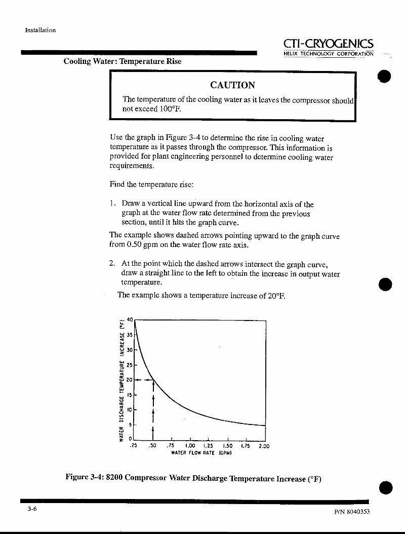
— 40 • tl 35 .4
CC ,-P = 30
25
CC a. ta 20 2
15 CC
X 10
8 5
wc̀ ti
0
.25 .50 .75 1.00 1.25 1.50 1.75 2.00 WATER FLOW RATE (GPM)
Installation
CTI-CRYOGENICS HELIX TECHNOLOGY CORPORATION
Cooling Water: Temperature Rise
CAUTION •
The temperature of the cooling water as it leaves the compressor should not exceed 100°F.
Use the graph in Figure 3-4 to determine the rise in cooling water temperature as it passes through the compressor. This information is provided for plant engineering personnel to determine cooling water requirements.
Find the temperature rise:
1. Draw a vertical line upward from the horizontal axis of the graph at the water flow rate determined from the previous section, until it hits the graph curve.
The example shows dashed arrows pointing upward to the graph curve from 0.50 gpm on the water flow rate axis.
2. At the point which the dashed arrows intersect the graph curve, draw a straight line to the left to obtain the increase in output water temperature.
The example shows a temperature increase of 20°F.
Figure 3-4: 8200 Compressor Water Discharge Temperature Increase (°F)
3-6 P/N 8040353

198-212 208V 180-212
Operating Voltage Range
60 Hz
50 Hz
Voltage Adjustment
Switch S1 Position
8200 Compressor
Final Preparation of Compressor
1. Using a voltmeter, measure the phase-to-phase voltage from the power source. Compare this voltage to the following table and position the voltage range selector switch to the "208V" or "220V" position as required. Also, set the frequency selector switch to the 50 Hz or 60 Hz position, as appropriate. See Figure 1-2 for location of selector switches.
Table 3-1: Voltage Specifications
2. Ensure that water is turned on for the water-cooled compressor.
3. Set the compressor ON/OFF switch (3) to OFF. Connect the input-power cable to the power source Refer to Table 1-1, for electrical power requirements.
4. Turn the compressor switch to the ON position and allow the com-pressor to run for 15 minutes to stabilize the oil circuit. Make sure that the compressor fan operates freely in the air-cooled compres-sor.
5. Switch off the compressor and disconnect the input-power cable.
6. Install the compressor in its permanent location on a level surface. Air cooled units must have a minimum clearance of 12 inches at the front and back for adequate airflow.
Connecting the Compressor to the Cold Head
Make the connections between the cryopump and compressor. See Figure 3-5.
1. Remove dust plugs and caps from the supply fittings and return lines, compressor, and cold head. Check all fittings.
2. Connect the helium-gas return line from the gas-return connector on the rear of the compressor to the gas-return connector on the cold head.
CTI-CRYOGENICS HELIX TECHNOLOGY CORPORATION
■111111■1•11111■1111111111111■1 P/N 8040353 3-7

Installation
al-CRYOGENICS HELIX TECHNOLOGY CORPORATION
3. Connect the helium-gas supply line from the gas-supply connector on the rear of the compressor to the gas-supply connector on the cold head.
4. Attach the supply and return line identification decals (CTI-sup-plied) to their respective connecting piping ends.
5. Verify proper helium supply static pressure by confirming that the helium pressure gauge reads 245-250 psig (1690-1725 kPa), in an ambient temperature range of 60 to 100°F (16 to 38°C).
If the indicated pressure is higher than 250 psig (1725 kPa), reduce the pressure as follows:
a. Remove the flare cap from the gas charge fitting located on the rear of the compressor.
b. Open the gas charge valve very slowly. Allow a slight amount of helium gas to escape until the helium pressure gauge reads 250 psig (1725 kPa).
c. Close the gas charge valve and reinstall the flare cap.
If the indicated pressure is lower than 245 psig (1690 kPa), add helium gas as described in Adding Helium Gas.
6. Make the following electrical connections.
WARNING The compressor ON/OFF power switch on the front of the compressor must be in the OFF position before making any and all electrical connec-tions.
a. Connect the cold head power cable to the rear panel of the compressor and the other end to the electrical power con-nector on the high-vacuum pump cold head.
b. Connect the compressor input power cable to the power source.
c. Turn on compressor.
d. Your system is now ready for operation.
•
3-8 P/N 8040353

Roughing Pump
Air Pressure (60-80 psi)
Nitrogen (40 80 psi)
8200 Compressor
Cil-CRYOGENICS HELIX TECHNOLOGY CORPORATION
User's Vacuum
Chamber
On-Board Cryopump
Helium Supply Line
RNA •
Helium Return Line
On-Board Power Cable I U I
I It
1 el II I
Figure 3-5: Typical 8200 Compressor Installation
P/N 8040353 3-9

Installation
CTI-CRYOGENICS HELIX TECHNOLOGY CORPORATION
■
•
3-10 P/N 8040353

8200 Compressor
CTI-CRYOGENICS HELIX TECHNOLOGY CORPORATION
Section 4 - Maintenance Procedures
WARNING Always disconnect the compressor from all sources of electrical power before performing any maintenance procedures.
Scheduled Maintenance
The only scheduled maintenance required on the 8200 Compressor is replacement of the compressor adsorber (P/N 8080255K001) every 12 months.
Removing the Compressor Adsorber
1. Shut down the compressor.
2. Disconnect the compressor input power cable from its electrical power source.
3. Disconnect the flex lines from the gas-return and gas-supply con-nectors at the rear of the compressor.
4. Remove the screws holding the compressor rear grille, rear panel, front panel and cover (Figure 1-2). Front and rear panels remain in place.
5. Use the two wrenches (supplied) to avoid loosening the body of the coupling from its adapter.
6. Unscrew the two self-sealing coupling halves quickly to minimize gas leakage as shown in Figure 4-1.
7. Disconnect the adsorber-inlet self-sealing coupling as shown in Figure 4-1.
8. Remove the bolts, nuts, and washers that secure the adsorber to the base of the compressor. Save all nuts, bolts, and washers for install-ing the replacement adsorber.
9. Carefully lift the adsorber inward until the outlet self-sealing cou-pling clears the rear panel and remove the adsorber as shown in Figure 4-2.
10. Remove the adsorber from the compressor as shown in Figure 4-2.
1-7N tiU4U.3 3 4-1

WARNING Depressurize the adsorber before disposing of it. Attach the depressur-ization fitting (included in the Installation and Scheduled Maintenance Tool Kit) to the coupling half at either end of the adsorber and tighten it slowly.
—Compressor Base
Maintenance Procedures
CTI-CRYOGENICS HELIX TECHNOLOGY CORPORATION
Compressor Rear —IN- Panel
•
This 1 1/8 in. wrench holds the coupling in a station-ary position.
This 1 3/16 in. wrench is used to loosen the self sealing coupling connector. Note the direction of the large arrow.
This 1 1/8 in. wrench holds the coupling in a station-ary position.
This 1 3/16 in. wrench is used to tighten the self sealing coupling connector. Note the direction of the large arrow.
To Disconnect The Coupling To Connect The Coupling
Figure 4-1: Disconnecting/Connecting the Adsorber Self-Sealing Coupling
Figure 4-2: Removing the Adsorber from the Compressor
4-2 P/N 8040353
8200 Compressor
CFI-CRYOGENICS HELIX TECHNOLOGY CORPORATION
Installing the Compressor Adsorber
• 1. Install the replacement adsorber as follows:
a. Remove the dust caps from the self-sealing coupling halves at each end of the replacement adsorber.
b. Write installation date on the adsorber decal.
c. Install the replacement adsorber following the steps for compressor adsorber removal in reverse order. Use the hard-ware saved in step 5 above.
2. Connect the adsorber to the compressor internal piping. Refer to Figure 4-1.
a. Check the self-sealing connector flat rubber gasket to make sure that it is clean and properly positioned.
CAUTION
Make sure to hold fast on the left coupling nut while tightening the right coupling nut, as shown in Figure 4-1.
b. Make the first turns by hand and then firmly seal the con-nection using the two wrenches until the fittings "bottom". Refer to Figure 4-1, for proper coupling of the self-sealing connection
3. Replace the cover and the front and rear grilles and secure them
4. Ensure that the pressure gauge reads 245-250 psig (1690-1725 kPa). If additional gas pressure is required, follow the instructions in, Adding Helium Gas.
5. Reconnect the return and supply flex lines to the compressor.
6. Connect the compressor input power cable to the electrical power source.
Unscheduled Maintenance
Suggested Unscheduled Maintenance Equipment
It is advisable to keep on hand the unscheduled maintenance equipment and disposable supplies listed below.
1. Helium, 99.999% pure.
2. Pressure regulator (0-3000/0-400 psig).
3. Maintenance manifold, P/N 8080250K003*.
P/N 8040353 4-3

Maintenance Procedures
al-CRYOGENICS HELIX TECHNOLOGY CORPORATION
4. Helium charging line terminating in a 1/4-inch female flare fitting, P/N 7021002P001.
5. Installation and Scheduled Maintenance Tool Kit, P/N 8032040G004.
*Available from stock; consult the factory or your sales representative.
Adding Helium Gas
Use only 99.999% pure helium gas.
CAUTION
If the compressor helium pressure gauge reads 0, decontamination is required. Refer to decontamination procedures under, Helium Circuit Decontamination, or contact the Product Service Department.
1. A User-supplied helium charging line terminating in a 1/4-inch female flare fitting, and a two-stage pressure regulator rated at 0-3000/0-400 psig is required for this operation.
2. If you need to add helium more than once every several months, check for leaks caused by improperly connected self-sealing con-nections or any mechanical joint within the compressor.
There are two conditions that require the addition of helium gas:
1. Compressor not operating; helium pressure gauge reads 245 psig or below.
2. Compressor operating; helium pressure reads 270 psig, or below.
To add helium gas:
1. Attach a pressure regulator (0-3000/0-400 psig) and charging line to a helium gas (99.999% pure) bottle. DO NOT OPEN THE BOTTLE AT THIS TIME. Purge the regulator and charging lines as instructed in steps a through e below. Do not use helium gas that is less than 99.999% pure.
a. Open the regulator a small amount by turning the adjusting knob clockwise until it contacts the diaphragm, then turn approximately 1/8 to 1/4 turn more, so that the regulator is barely open.
b. Slowly open the bottle valve, and purge the regulator for 10 to 15 seconds. Turn the regulator knob counterclockwise until the helium stops flowing.
•
4-4 P/N 8040353

8200 Compressor
al-CRYOGENICS HELIX TECHNOLOGY CORPORATION
c. Connect the charge line to the helium pressure regu alor.
d. Remove the flare cap of the gas charge fitting on the rear of the compressor. Loosely connect the charge line to the charge fitting.
e. Set the helium pressure regulator to 10 to 25 psig (70-125 kPa). Allow helium gas to flow through the charging line and around the loosened flare fitting for 30 seconds to purge the charging line of air. Then tighten the flare nut at the end of the charge line.
(This procedure is required to ensure that both the regulator and the charging line will be purged of air and that the air trapped in the regulator will not diffuse back into the helium bottle. For best results, CTI suggests a dedicated helium bottle, regulator, and line, which are never separated, for adding helium.)
2. Set the helium pressure regulator to 300 psig (2070 kPa). Depend-ing on the compressor operating state, add helium gas:
a. If the compressor is running (approximately 2 hours operat-ing time) under normal operating conditions, slowly open the helium charge valve on the rear of the compressor. When the helium pressure gauge rises to 270 - 290 psig (1860 - 2000 kPa) tightly close the charge valve.
b. If the compressor is not running, slowly open the helium charge valve. When the helium pressure gauge rises to 245 -255 psig (1688 - 1757 kPa), tightly close the charge valve.
CAUTION
Add helium gas slowly to prevent relief valve blow-off.
3. Ensure that the helium charge valve on the compressor is tightly closed. Shut off the helium pressure regulator on the helium bottle and remove the charging line from the male flare fitting. Shut off the helium gas bottle valve. Reinstall the flare cap.
Helium Circuit Decontamination
Contamination of the helium-gas circuit is indicated by sluggish or intermittent operation (ratchetting) of the cold head drive mechanism. With severe contamination the cold head drive may seize and fail to operate. One of the major sources of contamination is using helium gas of less than the required purity. When performing the decontamination process, use only 99.999% pure-helium gas, and the regulator and charging line must be
P/N 8040353 4-5

Maintenance Procedures
CTI-CRYOGENICS HELIX TECHNOLOGY CORPORATION
properly connected and purged. This contamination procedure will remove contaminants from the cold head and/or compressor, thereby restoring system performance. The cold-trapping of contaminants inside the cold head during this procedure will also decontaminate the compressor if the contamination of the system is not severe. Separate decontamination of the compressor is required whenever the compressor has been opened to atmosphere, or the pressure dropped to zero.
Cold Head Decontamination Procedures
1. Cool down the cold head and operate it for one to three hours. If the system will not cool down, proceed to step 2. Operating the cold head will isolate the contaminants by "freezing" them in the cold head. The contaminants in the helium-gas circuit of the cold head tend to become frozen inside the cold head. The longer the cold head is operated beyond the one-hour period, the greater is the amount of contamination that becomes isolated inside the cold head.
2. Shut down the compressor as follows:
a. Close the Hi-Vac valve in your vacuum system.
b. Turn off the system.
CAUTION
Exposing the cryopump to atmosphere during warm-up will cause excessive water vapor adsorption by the charcoal of the 15K array.
3. Immediately disconnect the helium-gas supply and helium-gas return lines from the gas-supply and gas-return connectors at the rear of the compressor. Leave them attached to the cold head.
4. Attach the maintenance manifold (P/N 8080250K003) to the dis-connected ends of the helium-gas return and helium-gas supply lines.
5. Reduce the pressure in the cold head to a level of 45 psig by using the maintenance manifold.
6. Allow the second stage of the cold head to warm up to room tem-perature. Warm-up time can be reduced by purging the cryopump with warm dry argon or nitrogen gas. Using the gas heater, CTI P/N 8080250K020, will reduce warm-up time about 50 percent, and will maintain the gas temperature below the 150°F (66°C) limit.
7. Once the cold head has reached room temperature, attach a two-stage regulator (0-3000/0-400 psig) and charging line to a helium bottle (99.999% pure). DO NOT OPEN THE BOTTLE VALVE AT
•
4-6 P/N 8040353

8200 Compressor
CTI-CRYOGENICS HELIX TECHNOLOGY,
THIS TIME. Purge, the regulator and charging line as instructed inCORPORATION
steps a through e in, Adding Helium Gas. Do not use helium gas that is less than 99.999% pure.
8. Perform in sequence:
a. Backfill the cold head and helium-gas return and supply lines with helium to a static charge pressure of 245-250 psig (1690-1725 kPa) by adjusting the regulator to the required pressure, and opening the valve on the manifold. Close the valve when the pressure is correct.
b. Depressurize the cold head by slowly opening the ball valve and allowing the helium to bleed out slowly. Do not reduce the pressure to less than 30 psig or the cold head may be further contaminated.
c. Perform flushing steps a and b three more times.
d. Pressurize the cold head to the static charge pressure of245- 250 psig (1690-1725 kPa) and run the cold head drive motor for 10 to 30 seconds by actuating the cryopump ON/OFF switch to ON.
e. Perform steps b through d two more times for a total of 9 flushes and a total of 2 drive-motor runs.
9. Verify that the cold head is pressurized to the static charge pressure of 245-250 psig (1690-17255 kPa).
10. Disconnect the maintenance manifold from the helium-gas return and helium-gas supply lines.
11. Reconnect the helium-gas return and helium-gas supply lines to the return and supply connectors at the rear of the compressor. The cold head is now ready for operation.
Compressor Decontamination Procedures
The procedure to decontaminate a compressor is similar to the above procedure with certain exceptions.
• There is no need to operate the cold head before decontaminating the compressor.
• The maintenance manifold and helium-gas supply and helium-gas return lines will be connected to the supply and return fittings on the compressor.
1. Open the ball valve slightly on the maintenance manifold and
111111111■1111111111•111111■1 P/N 8040353 4-7

Maintenance Procedures
CTI-CRYOGENICS HELIX TECHNOLOGY CORPORATION
allow the helium to bleed out and depressurize the compressor (if pressurized) to 30 psig. •
2. Charge the compressor slowly to approximately 250 psig (1725 kPa) by opening the 1/8-inch valve on the maintenance manifold.
3. Run the compressor for about 30 seconds.
4. Repeat steps 1 and 2, one more time.
5. Disconnect the maintenance manifold from the helium-gas return and helium-gas supply lines.
6. Reconnect the helium-gas return and helium-gas supply lines to the return and supply connectors on the cold head. The compressor is now ready for operation.
NOTE: After connecting the compressor to the cryopump, and operating the system for a period of time, it may be necessary to decontaminate the cold head as some residual contamination from the compressor may become trapped in the cold head. If the entire system was reduced to zero psig (a broken flex line, for example), then the cold head and compressor would have to be decontaminated according to the cold head decontamination section, Compressor Decontamination Procedures.
4-8 P/N 8040353

Appendix A - Customer Support Centers
CTI-CRYOGENICS HELIX TECHNOLOGY CORPORATION
Appendix A - Customer Support Centers
Introduction
Refer to Table A-1 for the nearest Customer Support Center for technical assistance or service. North American customers may call 1-800-FOR-GUTS (1-800-367-4887) 24 hours a day, seven days a week. All other customers must call their local Customer Support Center.
Please have the following information available when calling so that we may assist you:
• Product Part Number
• Product Serial Number
• Product Application
• Specific Problem Area
• Hours of Operation
• Equipment Type
• Vacuum System Brand/Model/Date of Manufacture
A-1

United States and Canada
CTI-CRYOGENICS Mansfield Corporate Center Nine Hampshire Street Mansfield, Massachusetts 02048, U.S.A. Tel: 508-337-5000 or 800-447-5007 Fax: 508-337-5169
Dial 1-800-FOR-GUTS (1-800-367-4887) 24 hours a day, seven days a week.
United States and Canada
CTI-CRYOGENICS 3350 Montgomery Drive Santa Clara, California 95054, U.S.A. Tel: 408-727-8077 or 800-447-5007 Fax: 408-988-6630
Dial 1-800-FOR-GUTS (1-800-367-4887) 24 hours a day, seven days a week.
pplawgYem 10rniur -2911 Aso:
:CTI4CRYOQM 4120, ,Frei Austin, Tel:
United States an Cana
even. 'a
24 hourt--ada 0-F04 :GPI'
France
CTI-CRYOGENICS, SA Domaine Technologique de Saclay 4, rue Rene Razel, Bat Apollo F-91892 Orsay Cedex France Tel: 331-6985-3900 Fax: 331-6985-3725
United Kingdom
CTI-CRYOGENICS Ltd. Fleming Road Kirkton Campus Livingston, West Lothian Scotland EH54 7BN Tel: 441-506-460017 Fax: 441-506-411122
Appendix A - Customer Support Centers
CTI-CRYOGENICS HELIX TECHNOLOGY CORPORATION
Table A-1: Customer Support Center Locations •
A-2

erm,egY0dEki .theeng
ac Atpa as
.11y0 0 Pef 660 Japan
$440. Anosogi
CT
2'Corporation 644'06
SingapOre. Tel: 65 FARE
aysial,Philipptiles)
Appendix A - Customer Support Centers
CTI-CRYOGENICS HELIX TECHNOLOGY CORPORATION
Table A-1: Customer Support Center Locations (Continued)
Taiwan, Hong Kong, and China
CTI-CRYOGENICS Challentech International Corporation No. 1, Lane 9, Pateh Road Hsin-Chu 300, Taiwan, R.O.C. Tel: 886-35-614211 Fax: 886-35-614210
Australia, New Zealand, and Tasmania
CTI-CRYOGENICS AVT Services Pte. Ltd Unit 1, 12 Pioneer Avenue Thornleigh NSW 2120 Sydney, Australia Tel: 612-4810748 Fax: 612-4810910
A-3

Appendix A - Customer Support Centers
CTI-CRYOGENICS HELIX TECHNOLOGY CORPORATION
•
A-4

Problem Possible Cause
Corrective Action
1) The thermal protective switch (TS1) is closed, activat-ing the relay-trip coil in the ON/ OFF switch (SW1).
2) Incorrect phasing at input power.
1) Test switch (TS1) on air-cooled compressor, test (TS1) and (TS2) on water-cooled compres-sor. If continuity is found in any switch, contact the Product Ser-vice Department.
2) Correct phase sequence at input power cable.
1) System power ON/ OFF switch (CBI) and compressor switch (Si) remains in the ON posi-tion when switched on but the compressor will not run. Refer to Figure C-1 for identification of all electrical components
3) Excessive current drain has activated the series trip in the compressor ON/OFF switch.
3) Measure and record the current and contact the Product Service Department.
Systempower OFF sWittli remains in non; but will not r
compress
8200 Compressor
CTI-CRYOGENICS HELIX TECHNOLOGY CORPORATION
Appendix B - Troubleshooting Procedures
WARNING
Disconnect the compressor before performing any troubleshooting pro-cedures.
The compressor pump is hot after operating. Wait for the pump to cool down before working on the inside of the compressor
Table B-1: Compressor Troubleshooting Procedures
■11111■111■11111•11111■ P/N 8040353 B-1

Appendix B - Troubleshooting Procedures
CTI-CRYOGENICS HELIX TECHNOLOGY CORPORATION
Table B-1: Compressor Troubleshooting Procedures
Possible Cause Problem Corrective Action
3) Compressor stops after several minutes of operation and remains off.
1) High temperature of the compressor is caused by insuf-ficient cooling water, resulting in the opening of thermal pro-tective switch (water-cooled compressor only).
2) After turn-off, very cold cooling water was left running through the compressor. The resulting low oil temperature has caused a restriction of oil flow through the metering ori-fice during startup.
1) Confirm that cooling water to the compressor is flowing. Con-firm that proper cooling water flow rate and pressure exist by referring to Figure 3-3.
2) Turn on the compressor and allow it to run until it has stopped several times, allowing the oil temperature to rise and the com-pressor to operate continuously for one hour minimum.
3) Very cold cooling water is circulating through the com-pressor. The resulting low oil temperature causes a restriction of oil flow through the metering orifice during startup.
4) Ambient temperature is unusually high resulting in the opening of the thermal protec-tive switch (air-cooled com-pressor only).
5) Insufficient helium supply pressure is indicated by the sup-ply pressure gauge.
6) High temperature of the compressed helium in the dis-charge line from the compres-sor pump has tripped the thermal protective switch.
7) Mechanical seizure.
3) Recheck for proper cooling water temperature per, Cooling Water Requirements (Water-Cooled Compressors Only).
4) Provide a free flow of air to the compressor. Confirm a 12-inch (30 cm) clearance at the front and back of the compressor. Confirm unobstructed and clean heat exchanger surfaces.
5) Add helium per, Unscheduled Maintenance.
6) Confirm that oil is visible in the compressor sight glass (air-compressor only).
7) Contact the Product Service Department.
•
B-2 P/N 8040353

Corrective Action _
Problem Possible Cause
8) Compressor operates but cold head motor does not run.
1) Loose or defective cable. 1) Check cold head cable.
AEI
10iiterrintlen voltage
4) Compressor pumpa stops after several nun utes of operating and then switches ON...`and OFF LAt shortintervals.
uitf-Loyorrotooigoogo between 198
i„:, 250Yiii50:114ia,40ft 4 --"iumagv,, 220Yr MWESS
8200 Compressor
CTI-CRYOGENICS HELIX TECHNOLOGY CORPORATION
Table B-1: Compressor Troubleshoofing Procedures
■111■1■111•11111=1111111111111MIN P/N 8040353
B-3

Appendix B - Troubleshooting Procedures
CFI-CRYOGENICS HELIX TECHNOLOGY CORPORATION
•
•
• B-4
P/N 8040353

8200 Compressor
CTI-CRYOGENICS HELIX TECHNOLOGY CORPORATION
• Appendix C - Electrical Schematics for 8200 Compressor
•
• P/N 8040353 C-1

Appendix C - Electrical Schematics for 8200 Compressor
cri-CRYOGENICS HELIX TECHNOLOGY CORPORATION
•
• C-2
P/N 8040353

8200 Compressor
CT-I-CRYOGENICS HELIX TECHNOLOGY CORPORATION
• Control Module of the 8200 Compressor
1. Overtemperature Resistor 2. Run Capacitor, 35 pf 3. Start Capacitor, 119 pf 4. Transformer 5. Phase Monitor 6. Voltage Selector Relay 7. Main Circuit Breaker 8. Circuit Breaker, 3A
R1 C1 C2 T2
PM K2
CB1 CB2
9. Circuit Breaker, 3A CB3 10. Voltage Selector Switch S1 11. Frequency Selector Switch S2 12.Overtemperature Trip Relay K1 13. Transformer T1 14. Motor Start Relay CR1 15. Meter, Elapsed Time ETM
Figure D-1: Components in the Electrical Control Chassis of the 8200 Compressor Three-Phase Scott-T Configuration
ill111111■1111111=11111
Appendix D - Components in the Electrical
• P/N 8040353 D-I

•
Appendix D - Components in the Electrical Control Module of the 8200 Compressor
al-CRYOGENICS HELIX TECHNOLOGY CORPORATION •
1. Coldhead Phase-Shifting ResistorR3 9. Circuit Breaker, 3A CB2 2. Overtemperature Resistor R1 10. Circuit Breaker, 3A CB3 3. Run Capacitor, 35 pf C1 11. Voltage Selector Switch S1 4. Start Capacitor, 119 pf C2 12. Frequency Selector Switch S2 5. Transformer T2 13. Relay, Trip Relay K1 6. Run Capacitor, 2 pf C4 14. Transformer T1 7. Run Capacitor, 6 pf C3 15. Motor Start Relay CR1 8. Main Circuit Breaker CB1 16. Meter, Elapsed Time ETM
Figure D-2: Components in the Electrical Control Chassis of the 8200 Compressor - Single-Phase RC Configuration •
D-2 P/N 8040353

8200 Compressor
CTI-CRYOGENICS HELIX TECHNOLOGY CORPORATION
Appendix E - Flow Diagrams for 8200 Air- Cooled and Water-Cooled Compressors
Compressor Gas and Oil Flows
Refer for Figure E-1 or Figure E-2 while reviewing this subsection.
Helium returning from the cold head enters the compressor, and a small quantity of oil is injected into the gas stream, thereby overcoming helium low specific head and inability to carry heat produced during compression. Helium is then compressed and passed through a heat exchanger for removal of compression-caused heat. The helium flows through a bulk oil separator, oil-mist separator, and helium filter cartridge, where oil and contaminants are removed.
A differential pressure relief valve in the compressor limits the operating pressure differential between the helium supply and return lines, thereby allowing compressor operating without cold head operation. When cold head operation reaches a steady-state condition, further pressure regulation is unnecessary.
P/N 8040353 E-1
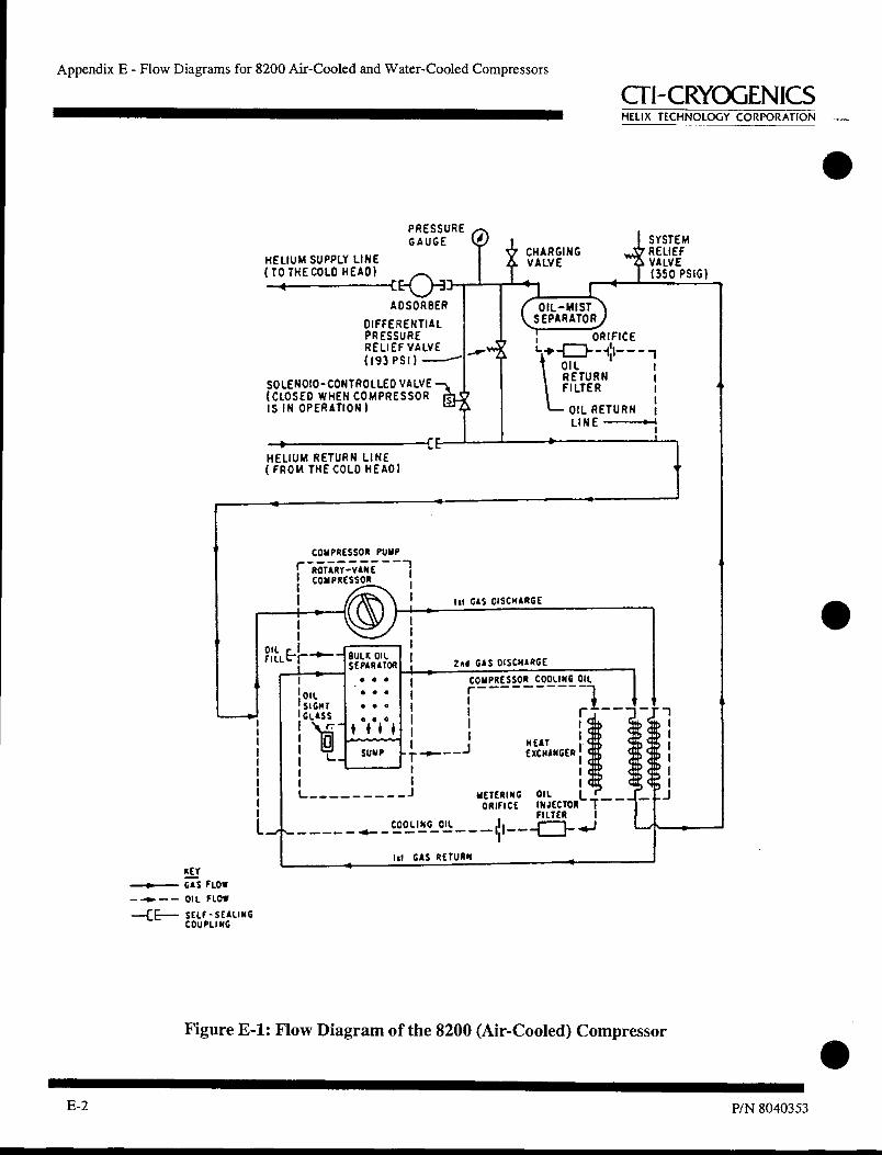
L_
I OIL SIGHT GLASS
L_
Appendix E - Flow Diagrams for 8200 Air-Cooled and Water-Cooled Compressors
al-CRYOGENICS HELIX TECHNOLOGY CORPORATION --
PRESSURE GAUGE
HELIUM SUPPLY LINE ( TO THE COLD HEAD) C
ADSORBER
DIFFERENTIAL PRESSURE RELIEF VALVE (193 PSI)
SOLENOIO-CONTROLLED VALVE (CLOSED WHEN COMPRESSOR IS IN OPERATION )
1 1 4 OIL-MIST
1 ORIFICE L ... -ED- -I:1- - -1
OIL RETURN FILTER
OIL RETURN LINE --*-I
SYSTEM V CHARGING RELIEF A VALVE .4. VALVE
(350 PSIG)
HELIUM RETURN LINE ( FROM THE COLD HEAD)
COMPRESSOR PUMP
r ROTART-VANE 1
COMPRESSOR
OFil
Ll
I r SULK OIL
I
SEPARATOR • • •
•■••■••- 111..
111 GAS OiSCHARGE
2AA GAS OISCNARGE
COMPRESSOR COOLING OIL r
HEAT EXCHANGER
COOLING OIL
METERING OIL ORIFICE INJECTOR 'T
FILTER I
4=3- .11 —IC I
III GAS RETURN
•
• 1
HET GAS FLOW Ott FLOW
-SEALING
Figure E-1: Flow Diagram of the 8200 (Air-Cooled) Compressor
•
E-2 P/N 8040353

HELIUM SUPPLY LINE ( TO THECOLD HEAD)
PRESSURE GAUGE
CHARGING VALVE
SYSTEM ,VC RELIEF -44 VALVE
(350 PSIG)
ADSORBER
DIFFERENTIAL PRESSURE RELIEF VALVE (193 PSI)
SOLENOID-CONTROLLED VALVE (CLOSED WHEN COMPRESSOR IS IN OPERATION )
C
SEPARATOR) OIL-MIST
ORIFICE + ED- - -6- - - -1 v- OIL RETURN FILTER
OIL RETURN LINE
COMPRESSOR PUMP T.: 0 R TARY-VANE
COMPRESSOR
0 0
0 0 BULK OIL
SEPARATOR
tototototo oto nil s' E.4
I FILL
L -I METERING ORIFICE
HEAT EXCHANGER
OIL INJECTOR L T - FILTER I
-
• 0 0 0 0 0 0 0 O 0 0 0 0 0 0 o
r-', oe 00000 0 0 0 0 0 0 0 J..
OIL SIGHT GLASS - SUMP
L COOLING OIL
GAS DISCHARGE
gi• r-HEAT
EXCHANGER
O COMPRESSOR 0 0 COOLING OIL
8200 Compressor
CTI-CRYOGENICS HELIX TECHNOLOGY CORPORATION
HELIUM RETURN LINE ( FROM THE COLD HEAD)
GAS FLOW
-4.- OIL FLOW
—CE-- SELF-SEALING COUPLING
Figure E-2: Flow Diagram of the 8200 (Water-Cooled) Compressor
1111111111•1111111■11•111111111111■1111 P/N 8040353 E-3

Appendix E - Flow Diagrams for 8200 Air-Cooled and Water-Cooled Compressors
CII-CRYOGENICS HELIX TECHNOLOGY CORPORATION
•
•
• E-4 P/N 8040353

PART 6:
Temperature Controller
Manual
See Lakeshore Model 331
Temperature Controller manual.