Physics 310 Lecture 7a Waveform Generators &...
15
Physics 310 Lecture 7a – Waveform Generators & Timers 1 Equipment Lect. 7a(short) ppt Spring-ball solid Handout : Lab #7 Waveform Shaping Comparator (Schmitt Trigger is better version) – sine or triangle to square wave Integrator – square to triangle wave Differentiator – square wave to “pulses” Oscillators (just a few examples) Crystal oscillators – LC equivalent Relaxation oscillators – neon lamp, op-amp square-wave oscillator, Wein bridge 555 Timer Basic operation Circuit examples – One-shot (monostable operation), astable operation Waveform Generators – ICL8038 is an example, external components determine frequency -Need a better explanation on the 555 timer if thats important for us to know.. It was only a small section in the chapter. You bet; however, I‟m going to defer that until tomorrow; I‟ll deal with circuits built of more familiar components today. 10-1 Intro. -What application does an oscillator have in a circuit. Like what does it do..? Often you want a circuit to generate a specific waveform – maybe a sine wave to help smoothly drive a motor, maybe a square wave to blink a light or count off seconds, or maybe a sawtooth wave to drive stick-slip motion of a piezo. Here are different circuits that generate different outputs from scratch or shape given inputs into different outputs. 10-2 Waveform Shapers We‟ve actually already met some of these „shapers‟, though we weren‟t necessarily thinking them in these terms. Given one kind of periodic input they generate a different kind of periodic output. Wed. 3/7 Thurs. 3/8 Fri. 3/9 Ch 10: Oscillators & Timers - Beginning Ch 10: Oscillators & Timers – Rest of; Lab 7: Oscillators & Timers Lab 7: Oscillators & Timers; Quiz Ch 10 HW 7: Ch10 Pr. 2*, 6,7,8; Lab 7 Notebook
-
Upload
truongkien -
Category
Documents
-
view
223 -
download
2
Transcript of Physics 310 Lecture 7a Waveform Generators &...

Physics 310
Lecture 7a – Waveform Generators & Timers
1
Equipment
Lect. 7a(short) ppt
Spring-ball solid
Handout:
Lab #7
Waveform Shaping
Comparator (Schmitt Trigger is better version) – sine or triangle to square wave
Integrator – square to triangle wave
Differentiator – square wave to “pulses”
Oscillators (just a few examples)
Crystal oscillators – LC equivalent
Relaxation oscillators – neon lamp, op-amp square-wave oscillator, Wein bridge
555 Timer
Basic operation
Circuit examples – One-shot (monostable operation), astable operation
Waveform Generators – ICL8038 is an example, external components determine frequency
-Need a better explanation on the 555 timer if thats important for us to know.. It was only a small section in the chapter.
You bet; however, I‟m going to defer that until tomorrow; I‟ll deal with circuits built of more
familiar components today.
10-1 Intro.
-What application does an oscillator have in a circuit. Like what does it do..?
Often you want a circuit to generate a specific waveform – maybe a sine wave to help
smoothly drive a motor, maybe a square wave to blink a light or count off seconds, or maybe
a sawtooth wave to drive stick-slip motion of a piezo. Here are different circuits that
generate different outputs from scratch or shape given inputs into different outputs.
10-2 Waveform Shapers
We‟ve actually already met some of these „shapers‟, though we weren‟t necessarily thinking
them in these terms. Given one kind of periodic input they generate a different kind of periodic
output.
Wed. 3/7
Thurs. 3/8
Fri. 3/9
Ch 10: Oscillators & Timers - Beginning
Ch 10: Oscillators & Timers – Rest of; Lab 7: Oscillators & Timers
Lab 7: Oscillators & Timers; Quiz Ch 10
HW 7: Ch10 Pr. 2*, 6,7,8; Lab 7 Notebook

Physics 310
Lecture 7a – Waveform Generators & Timers
2
10-2.1 Comparator (with Schmidt trigger)
We already met the Schmitt Triggered comparator, but since that was before break (and an
exam over different material), maybe this is a nice place to ease us back in.
vout
R1
-
+
Vin
R2
Vref
V+
V-
Analysis
o Now, this is not a negative-feedback configuration (the negative input is not
linked to the output) so we don‟t get to invoke the Golden Rule to analyze it,
instead, we need to go back to basics:
)( ininout VVAV unless it hits the + or – “rail” trying, i.e., V+, V
-.
o In this circuit, Vin is wired to Vin- and we think of the voltage on Vin+ as a
reference, sometimes referred to as Vref.
o So, if inVrefV then outV
V
V
o But that‟s not all; the two resistors can be seen as making a voltage divider so that
21
1
RR
RVV outref so Vref flips between
21
1
RR
RVVref and
21
1
RR
RVVref as Vout flips. The effect is to make Hi/Lo output that‟s
impervious to (small) noise.
So, when the input signal‟s upward bound, it has to cross +Vref, to flip the output
up, and then when it‟s downward bound it has to cross –Vref to flip the output down. Note that
I‟ve illustrated a situation in which the rails are symmetric around 0, like +/-15V; that would
make the reference thresholds symmetric and the square wave‟s high & lo values equal and
opposite. One needn‟t have that symmetry; for example, sometimes a comparator will be wired
up with the negative rail at 0, which would obviously shift up the negative reference and the
„low‟ value of the output would only be 0.
V+
V-
+Vref
-Vref
Vin
Vout

Physics 310
Lecture 7a – Waveform Generators & Timers
3
10-2.1.1 Sine-to Square Wave
If the input is anything with a regular period (and not too noisy) this circuit can generate a
square wave. The book shows a special case of a) sine wave input and b) V- = ground.
Because these are asymmetric limits, the reference points aren‟t symmetric around 0 (they‟re
more like –Vref = 0, +Vref = 100mV) whereas the input signal, a sine wave, is symmetric
around zero, so the output is asymmetric – it spends longer Hi than it does LO since the input
spends longer below 100mV than it does above 0 V.
10-2.2 Differentiator & Integrator
vout
R
-
+
C
Vin
vout
R1
-
+
C
Vin
Differentiator Integrator
What if you already have a square wave, perhaps from a Schmitt triggered comparator, what
other wave forms could you shape from that?
Integrator
o Q: If the input for an integrator were a +/- square wave, what would its output be?
A: A triangle wave (note: since the integrator‟s output is really the
negative integral, the triangle wave would slope down for positive input
and up for negative input).
o Similarly, if the input were a +/0 square wave, then the integrator would make a
jagged stair-step (decreasing during the + input and holding steady during the 0).
Differentiator
o Q: How about for a differentiator, what would be the output when fed a square-
wave input?
o A differentiator would output spikes whenever the square wave input transitioned.
(like the integrator, the differentiator outputs negative derivative, so spike up for a
down transition and spike down for up transition.)
This “spike” or “blip” is what the text refers to as a “pulse.” In the ideal, a perfect
square wave would have perfectly vertical sides and so the derivative would be infinite. Of
course, that‟s impractical; usually the sides have a bit of slope and curve at the ends:
V+
V-
Vint
Vin
Vdiff
Side of square - Derivative

Physics 310
Lecture 7a – Waveform Generators & Timers
4
3. To my understanding a pulse wave is really an asymmetric square wave. On pg 217 Diefenderfer says that a differentiator circuit is used to convert a square wave to a pulse wave. Wouldn't the differentiating a square wave result in blips rather than sustained asymmetrical voltages? Yes. By “pulse” he means what you mean by “blip.” He goes on to say that if the input is a single pulse, then the output pulse width can be modified. How does this work? He just means that, while the input might be a square-ish pulse that lasts for, say 10 ms, with a side taking 2 s
to transition from „lo‟ to „hi‟, then the output is a pair of + and - (curvy) pulses 10ms apart and with times of
only 2 s. If you have circuitry down the line that responds to only, say positive pulses, then as far as it‟s
concerned, this comparator swapped a 10ms pulse for a 2 s pulse.
Wave-Form Generators
The rest of the chapter is about circuits that don’t require external, periodic signals to drive them;
these circuits generate their oscillating outputs from scratch. I‟m doing things a little out of the
book‟s order so I can bring more familiar types of circuits forward and postpone less familiar
ones. I should note that almost all of these generators are a little peculiar; we‟ll be able to get the
general gist of them and completely understand most of the logical steps, but they all involve one
or another „cute‟ step that‟s a little harder to reason out. So, don‟t feel like you have to master
these, just mostly understand them.
Two types. In broad strokes, there are two types of oscillators – Relaxation and Resonance. To
get a qualitative feel for how each type works, let‟s think about their mechanical analogs.
Resonance. o Mechanical Analog. For the Resonance oscillator, think of a mass bobbing on a
spring or a kid on a swing swinging back and forth. In either case, there‟s a
frequency at which the system naturally oscillates back and forth without any
external help from you or me, that‟s the „resonance frequency.‟ Of course, as
you‟re quite familiar, once you set your mass bobbing or kid swinging, it‟s
oscillations will begin decaying – while the period of oscillation remains constant,
thanks to friction, drag, etc., the amplitude of oscillation gets smaller and smaller
until the thing‟s essentially stopped moving. So, if you want it to keep oscillating,
you need to give it well timed nudges. In terms of energy, while friction is
sucking energy out of the system, your nudges are counter acting that by putting
energy back into the system. For the kid on the swing, you give a push once each
swing; of course, you make a point of pushing forward when the kid‟s moving
forward (not when the kid‟s moving backward – that would be
counterproductive.)
o Basic Ingredients. So, there‟s a system that naturally oscillates at its resonance
frequency, and there‟s someone giving nudges at the right time to keep the system
going in spite of energy loss due to friction. Those are the two pieces you‟ll see
in all the circuits that use resonance to generate an oscillating current & voltage.
Relaxation.
Physics 310
Lecture 7a – Waveform Generators & Timers
5
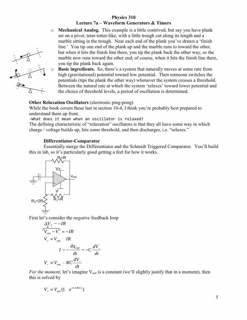
o Mechanical Analog. This example is a little contrived, but say you have plank
set on a pivot, teter-totter-like, with a little trough cut along its length and a
marble sitting in the trough. Near each end of the plank you‟ve drawn a „finish
line.‟ You tip one end of the plank up and the marble runs to toward the other,
but when it hits the finish line there, you tip the plank back the other way, so the
marble now runs toward the other end; of course, when it hits the finish line there,
you tip the plank back again.
o Basic ingredients. So, there‟s a system that naturally moves at some rate from
high (gravitational) potential toward low potential. Then someone switches the
potentials (tips the plank the other way) whenever the system crosses a threshold.
Between the natural rate at which the system „relaxes‟ toward lower potential and
the choice of threshold levels, a period of oscillation is determined.
Other Relaxation Oscillators (electronic ping-pong)
While the book covers these last in section 10-4, I think you‟re probably best prepared to
understand them up front. -What does it mean when an oscillator is relaxed?
The defining characteristic of “relaxation” oscillators is that they all have some way in which
charge / voltage builds up, hits some threshold, and then discharges, i.e. “relaxes.”
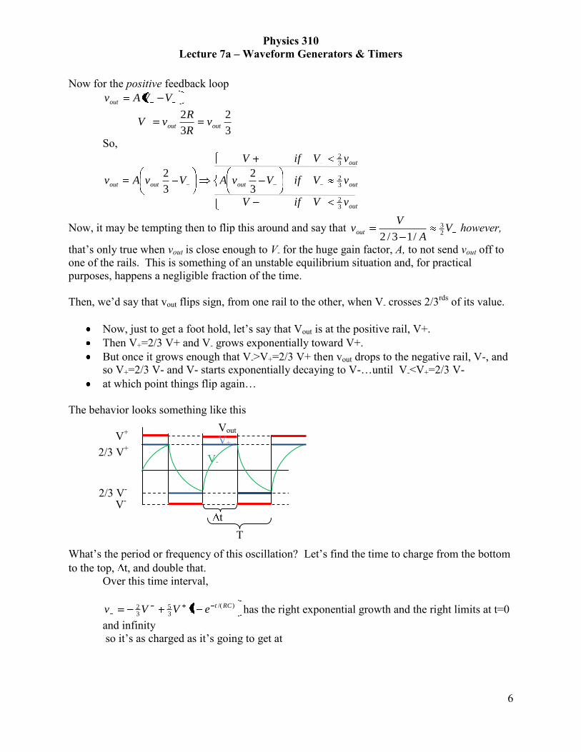
Differentiator-Comparator
Essentially merge the Differentiator and the Schmidt Triggered Comparator. You‟ll build
this in lab, so it‟s particularly good getting a feel for how it works.
vout
R2=2R
-
+
R1=R
V+
V-
Rf=R
First let‟s consider the negative feedback loop
IRVV
IRVV
IRV
out
out
f
dt
dVC
dt
dqI
cap
dt
dVRCVV out
For the moment, let‟s imagine Vout is a constant (we‟ll slightly justify that in a moment), then
this is solved by
)1( )/( RCt
out eVV
Physics 310
Lecture 7a – Waveform Generators & Timers
6
Now for the positive feedback loop
VVAvout
3
2
3
2outout v
R
RvV
So,
out
outout
out
outout
vVifV
vVifVvA
vVifV
VvAv
32
32
32
3
2
3
2
Now, it may be tempting then to flip this around and say that VA
Vvout 2
3
/13/2 however,
that‟s only true when vout is close enough to V- for the huge gain factor, A, to not send vout off to
one of the rails. This is something of an unstable equilibrium situation and, for practical
purposes, happens a negligible fraction of the time.
Then, we‟d say that vout flips sign, from one rail to the other, when V- crosses 2/3rds
of its value.
Now, just to get a foot hold, let‟s say that Vout is at the positive rail, V+.
Then V+=2/3 V+ and V- grows exponentially toward V+.
But once it grows enough that V->V+=2/3 V+ then vout drops to the negative rail, V-, and
so V+=2/3 V- and V- starts exponentially decaying to V-…until V-<V+=2/3 V-
at which point things flip again…
The behavior looks something like this
What‟s the period or frequency of this oscillation? Let‟s find the time to charge from the bottom
to the top, t, and double that.
Over this time interval,
)/(
35
32 1 RCteVVv has the right exponential growth and the right limits at t=0
and infinity
so it‟s as charged as it‟s going to get at
V+
V-
Vout
2/3 V+
2/3 V-
V+
V-
t
T

Physics 310
Lecture 7a – Waveform Generators & Timers
7
5ln
1
1
1
51)/(
)/(
54
)/(
35
34
)/(
35
32
32
RCt
e
e
eVV
eVVVv
RCt
RCt
RCt
RCt
Thus the
Full period is twice this
5ln22 RCtT
And the frequency is
5ln2
1/1
RCTf
(note: the text is missing this factor of ln(5).)
Going back through this argument in slightly more general terms (where the resistance values
aren‟t necessarily as shown)
12ln2
1
1
2
R
RCR
f
f
Double Inverter Oscillator
o The next oscillator circuit uses a component you haven‟t met yet; fortunately its
function is pretty easy to understand.
o Crash Course in Inverters. The “Inverter” is a logic chip that‟s essentially a
Comparator with the input and reference flipped.
When the input signal crosses below a lower threshold, the inverter‟s
output goes to the positive rail;
when the input crosses above an upper threshold, the output goes to a
negative rail (which is often simply ground.)
While a Comparator can be used to achieve this function, an even simpler bit of
circuitry works: something akin to the Transistor Switch. Just like the op-amp,
under the hood, the inverter is built of transistors. Like the op-amp, it draws
negligible current in it input (very large input impedance) and can source as much
current as you‟d reasonable want (very small output impedance).
Symbol. As you‟re slowly beginning to see, circuit diagrams involving
op-amps and the such often bother showing only the details that are
necessary for conveying the logic of the circuit (what it does to the signal),
not the other connections that „power‟ the chip. In that spirit, an Inverter
is symbolized with
This is pretty abstract, I grant. If it helps you to remember it, the lineage
is that the Follower is represented by the same symbol but without the dot
on the end. That makes some sense because a follower typically is an Op-
Amp (triangle) that just passes the signal through (line in, line out). An
Physics 310
Lecture 7a – Waveform Generators & Timers
8
inverter does the same thing, but gives you the logical opposite. The
dot/circle/knot represents the logical NOT. It‟s kind of juvenile, but
together the triangle and circle say “here take my input…NOT.”
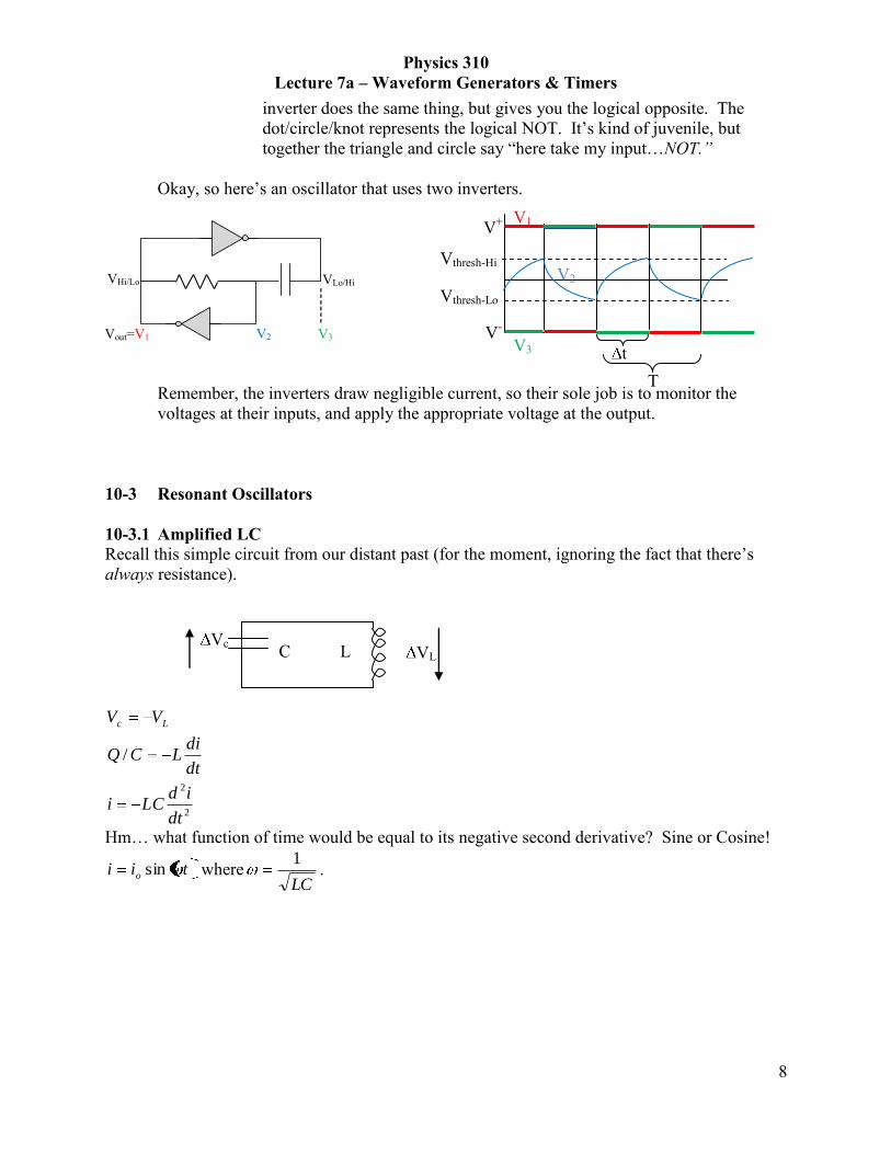
Okay, so here‟s an oscillator that uses two inverters.
VLo/Hi VHi/Lo
Vout=V1 V2 V3
Remember, the inverters draw negligible current, so their sole job is to monitor the
voltages at their inputs, and apply the appropriate voltage at the output.
10-3 Resonant Oscillators
10-3.1 Amplified LC
Recall this simple circuit from our distant past (for the moment, ignoring the fact that there‟s
always resistance).
2
2
/
dt
idLCi
dt
diLCQ
VV Lc
Hm… what function of time would be equal to its negative second derivative? Sine or Cosine!
tii o sin whereLC
1.
L VL Vc
C
V+
V-
V3
Vthresh-Hi
Vthresh-Lo
V2
V1
t
T

Physics 310
Lecture 7a – Waveform Generators & Timers
9
So, if you started off with a charged capacitor and then connected it to an inductor, the current
(and thus the voltage too) would oscillate back and forth sinusoidally at this frequency – it
generates a sine wave!
The mechanical analog is a mass on a spring – rather than tracking the motion of the charges, in
this circuit, track the motion of that mass – the spring/capacitor may be initially
compressed/+charged, so it starts pushing on the mass/charges through the inductor which has
some inertia so it slows this change in motion. But by the time the spring/capacitor becomes
unstretched/uncharged, the momentum of the mass / inductor, keeps things moving so that the
spring/capacitor gets even more stretched/-charged. Eventually the mass/charge stops moving
and starts going back the other way. The system oscillates back and forth.
Okay, now for the unfortunate part: there is always resistance, and that serves to drain energy out
of the system / decay the sine wave. So, if we want to use this as a sine wave generator, then we
need to put energy back into the system, boost up the amplitude. That‟s where an amplifier
comes in handy – amplify the voltage and send it back to drive the voltage. Some of the circuits
that follow are implementations of this kind of thinking – take something that naturally resonates
at a single frequency, and then amp it up to offset any losses.
For the mass on a spring, this would be like you‟re giving it a little nudge down/up each time it‟s
moving down/up. The exact timing of the nudge isn‟t too important, as long as it‟s down when
headed down, up when headed up.
1. I may be looking to far into this but I want to make sure I understand. On Pg. 218 is the diagram of the LC circuit. In the section where he says that one could overcome power loss by resupplying energy, he states that the energy should be resupplied at T1, T4, and T8. Would supplying the energy at T1 be incorrect? T1 does not appear to be at the same state as T4 and T8. Quantitatively, would we want to resupply the energy at the point in time when current is 0?
You are right that time 1 doesn‟t look quite like times 4 & 8; what matters is that the extra charge
gets driven onto the capacitor while it‟s charging up and/or driven off while it‟s discharging.
t
i
t
vL

Physics 310
Lecture 7a – Waveform Generators & Timers
10
10-3.2 Piezo Crystal Oscillator
Nature has made a handy LC circuit: a piezo-electric crystal. These are used all over the
place in clocks and watches. A Piezo-electric is a material that, when compressed or
expanded generates a voltage difference, proportional to the expansion/contraction, across its
sides. Now, since every chunk of material has a resonance frequency at which it would
easily vibrate when struck - tuning fork is an extreme example, but everything will do it,
then the idea is to “strike” the piezo with a voltage, then it will oscillate sinusoidally and,
meanwhile, generate a sinusoidally oscillating voltage.
How Piezos work:
We think of crystals as being built of atomic scale bricks, call the “unit cell”. Just to picture
one, one common “unit cell” is body-centered-cubic: imagine a cube with an atom on each
corner and one in the middle. Then imagine building a big, thick slab of such cubes stacked
on/under/by/infront/behind each other. That‟s a chunk of crystal. To a large extent, what
properties the “unit cell” has, simply scale up to the whole chunk.
Now a Piezo is special in two ways. First, there‟s a charge distribution within the unit cell,
and second the atomic bonds that hold it together are stiffer one way than another.
Imagine this 2-D crystal (it doesn‟t really work in 2-D, but you‟ll get the basic idea), where,
say, blue is positive and red is negative. If the charges are distributed just right, so that the
positives have, say about half as much charge as do the negatives, then the crystal is net
neutral and over large chunks the even and odd distributions average out.
Now say you compress the crystal; the splayed bonds will bend more easily than the aligned
bonds will compress, so it will look like this. Aside from getting wider and shorter, notice
that the red negatives are closer to the bottom than they used to be. If, in the unsquashed
version, the + and – charge distributions averaged out, in this squashed version, they cannot,
and there will be a net negative charge on the bottom and a net positive charge on the top.
Electrically, this looks like a capacitor.
When you compress and decompress the Piezo, the charge on the “capacitor plates” and thus
voltage developed increases and decreases. We can model the interaction between this
mechanical & voltage oscillation with the “plates‟” charging and discharging. Conveniently, a
mechanical dampened harmonic oscillator has an electronic analog in an LCR circuit (the
resistor sucks energy out of the system, like drag, the capacitor can store up and spend down
+Q
-Q
Physics 310
Lecture 7a – Waveform Generators & Timers
11
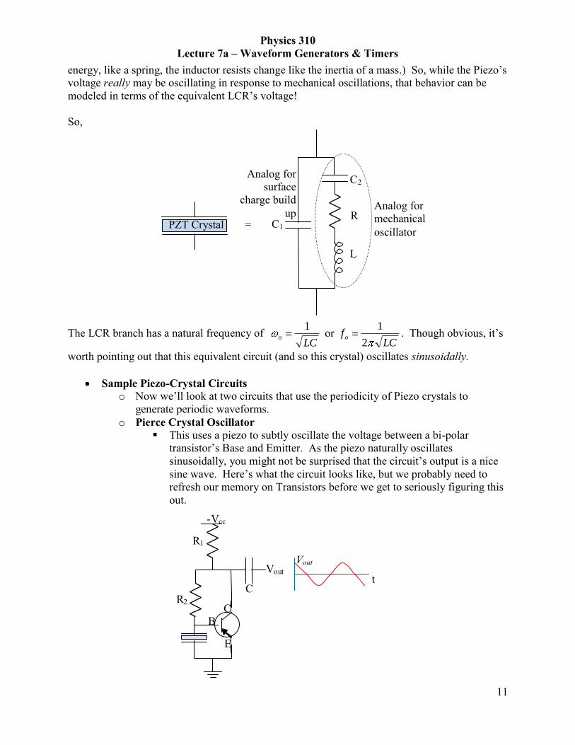
energy, like a spring, the inductor resists change like the inertia of a mass.) So, while the Piezo‟s
voltage really may be oscillating in response to mechanical oscillations, that behavior can be
modeled in terms of the equivalent LCR‟s voltage!
So,
C1
C2
R
L
The LCR branch has a natural frequency of LC
o
1 or
LCfo
2
1. Though obvious, it‟s
worth pointing out that this equivalent circuit (and so this crystal) oscillates sinusoidally.
Sample Piezo-Crystal Circuits
o Now we‟ll look at two circuits that use the periodicity of Piezo crystals to
generate periodic waveforms.
o Pierce Crystal Oscillator
This uses a piezo to subtly oscillate the voltage between a bi-polar
transistor‟s Base and Emitter. As the piezo naturally oscillates
sinusoidally, you might not be surprised that the circuit‟s output is a nice
sine wave. Here‟s what the circuit looks like, but we probably need to
refresh our memory on Transistors before we get to seriously figuring this
out.
C R2
E
B C
Vout
R1
-Vcc
t
Vout
PZT Crystal =
Analog for
mechanical
oscillator
Analog for
surface
charge build
up

Physics 310
Lecture 7a – Waveform Generators & Timers
12
Transistor Background. o PNP not NPN. First, a few things might look backwards
to you. The Vcc voltage supply line is explicitly marked as
negative (rather than positive) and the arrow in the
transistor (indicating the direction of charge-carrier motion
if Vcc were positive) points from the Emitter to the Base
(rather than the other way around). The reason things look
backwards is that we‟d mostly looked at circuits with NPN
structures, but this circuit uses a PNP transistor (Bass is p-
doped to have acceptors and the Emitter and Collector are
n-doped to have donors). So, the voltages are flipped, and
current flows in the opposite direction; those are the only
practical differences.
o VEB Not Constant. Since this relies on a property of
transistor‟s that we‟ve approximated away every single
time we‟ve analyzed transistor circuits, it‟s worth
reviewing a tad. Up to this point, it‟s been appropriate to
approximate the voltage difference between a bi-polar
transistor‟s Base and Emitter as a constant ~ 0.6V. A plot
of that would be a boring flat line – regardless of I, V was
0.6Volts. Of course, that‟s a simplification. Actually, the
current-voltage relation‟s more of an exponential.
o Except for when passing miniscule currents, the Emitter
and Bass have a voltage difference very close to 0.6V.
Thus we‟ve typically approximated it as such. However,
there is a low-current / low-voltage range for which voltage
changes significantly with current, and vice-versa.
Circuit Analysis. With this behavior in mind, let‟s return to the Pierce
Crystal Oscillator circuit and figure out how it works.
Superficial. Without being too rigorous, since the Piezo naturally
oscillates, EBV oscillates, which means that BI oscillates; of course,
BC II , so that means that IC oscillates (and it does so with much greater
amplitude than IB since >>1), which means that VC oscillates, and thus
both Vout and VEB oscillates, which returns us to the beginning of this
chain of reasoning. The resulting sine-wave signal‟s frequency can be
controlled to very high precision, say10-5
to 10-7
fractional error. That
means a watch timed by a quartz crystal might get off by 1 second every
day or every month.
I
VEB
~0.6V
Physics 310
Lecture 7a – Waveform Generators & Timers
13
Rigorous. A more rigorous analysis would use phasors and the piezo‟s
RCL equivalent (on page 5 of these notes) to model the piezo‟s role. It
would also have to model the emitter current‟s exponential dependence on
the voltage between it and the base. That doesn‟t sound like much fun, but
the basic pieces are then:
o 11RiVv ccc
o 22Rivv cB
o ciii 21
o pB iii2
o 1/ kTeV
oEBEeii
o BBEc iiii
o ppB Ziv
o
LRCC ZZZZ
pZ
21
11
1
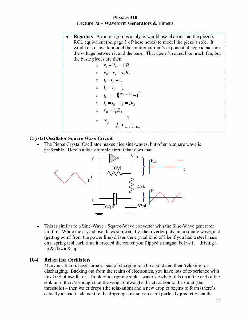
Crystal Oscillator Square Wave Circuit
The Pierce Crystal Oscillator makes nice sine-waves, but often a square wave is
preferable. Here‟s a fairly simple circuit that does that.
Vout
10M
2.2k
62pf 62pf
This is similar to a Sine-Wave / Square-Wave converter with the Sine-Wave generator
built in. While the crystal oscillates sinusoidally, the inverter puts out a square wave, and
(getting oomf from the power line) drives the crystal kind of like if you had a steel mass
on a spring and each time it crossed the center you flipped a magnet below it – driving it
up & down & up…
10-4 Relaxation Oscillators
Many oscillators have some aspect of charging to a threshold and then „relaxing‟ or
discharging. Backing out from the realm of electronics, you have lots of experience with
this kind of oscillator. Think of a dripping sink – water slowly builds up at the end of the
sink until there‟s enough that the weigh outweighs the attraction to the spout (the
threshold) – then water drops (the relaxation) and a new droplet begins to form (there‟s
actually a chaotic element to the dripping sink so you can‟t perfectly predict when the
t
V t
Vout
t
V

Physics 310
Lecture 7a – Waveform Generators & Timers
14
next drop will fall; we won‟t be wanting that in our electronics). We‟ll now consider a
few electronic oscillators like this.
10-4.1 Neon Lamp Oscillator
A simple strobe lamp exhibits this kind of behavior.
Vout
VB
R
C neon
lamp
Sparks Background. Central to this circuit‟s operation is a fact that you learned back in
Phys 232 – it takes a certain electric field strength to start a spark, but once it‟s initiated,
the spark can be self-sustaining even at a slightly reduced field strength. Of course, the
central phenomenon of a spark is the flow of ions through the air; it takes a high local
field to actually ionize an atom, but once an ion is generated, it can, with a lower field, be
accelerated enough so that it ionizes another atom upon collision.
Turning on and off the lamp. Now, a Neon lamp works by something like controlled
sparking. As the capacitor on the left of the circuit charges up, so do the electrodes in the
neon lamp, and thus the voltage difference between the lamp‟s two electrodes builds up.
When it gets high enough, around 60 V for most neon lamps, there‟s a big enough
electric field that the neon can be ionized, and so it can conduct an electrical current.
That current dis-charges the electrodes, and so the field weakens. But that‟s okay; as long
as there are some ions in the tube, they can be accelerated enough that they ionize the
neutral atoms when they collide, so the current continues even as the plates discharge.
Eventually, the field gets weak enough that the ions aren‟t sufficiently accelerated to
smash apart more ions and so there aren‟t any more ions and the lamp stops passing
current. So, the capacitor and the two electrodes start charging up again. The process
repeats itself, over and over.
For a simple RC circuit with Vb as the rail, the voltage across the capacitor is a function
of time, RCt
b eVtV /1)(
So, it would charge from 0 to Vx in time tx,
Vb Vf
Vx
0 tf tx

Physics 310
Lecture 7a – Waveform Generators & Timers
15
xb
b
b
xb
b
xx
VV
VRC
V
VVRC
V
VRCt lnln1ln
Similarly, it would take time tf to charge all the way to Vf from 0 Volts.
fb
bf
VV
VRCt ln
Then the time it takes to charge from Vx to Vf is just
fb
xb
xb
b
fb
bxf
VV
VVRC
VV
VRC
VV
VRCtt lnlnln
Now, to the extent that this charge-up time is much longer than the charge-down time,
this is roughly the total time for one cycle. Then the frequency is roughly one over this.
fb
xb
VV
VVRC
fln
11
Obviously, this approximation breaks down when the RC time constant is quite small, so
the charge time is about as short as the discharge time. Then we‟d need to think of a way
to quantify that and add it into our expressions for the period and the frequency.