Physics-04 (Leph 201504) 1. Details of Module and its ...
20
Physics 2019 Physics-04 (Leph_201504) Electronic Device Physics-04 (Leph_201504) 1. Details of Module and its structure Module Detail Subject Name Physics Course Name Physics 04 (Physics Part-2, Class XII) Module Name/Title Unit-10, Module-04: Amplitude Modulation Chapter-15: Communication Systems Module Id leph_201504_eContent Pre-requisites Frequency, wavelength, electromagnetic wave, antenna, transducer, band width, frequency range, signal, need for communication, common communication devices, electromagnetic wave transmission, channels of communication, need for modulation, types of modulation Objectives After going through this module the learners will be able to Understand Amplitude modulation Appreciate the need for Modulation index Know block diagram to show production and detection of amplitude modulated wave Be aware of applications of amplitude modulation Keywords Amplitude modulation, modulation index, graphical representation of amplitude modulated wave, application of amplitude modulated wave 2. Development Team Role Name Affiliation National MOOC Coordinator (NMC) Prof. Amarendra P. Behera Central Institute of Educational Technology, NCERT, New Delhi Programme Coordinator Dr. Mohd Mamur Ali Central Institute of Educational Technology, NCERT, New Delhi Course Coordinator / PI Anuradha Mathur Central Institute of Educational Technology, NCERT, New Delhi Subject Matter Expert (SME) Dinesh Tyagi Army Public School, Hindon Review Team Prof. V. B. Bhatia (Retd.) Associate Prof. N.K. Sehgal (Retd.) Prof. B.K. Sharma (Retd.) Delhi University Delhi University DESM, NCERT, New Delhi
Transcript of Physics-04 (Leph 201504) 1. Details of Module and its ...
Physics 2019 Physics-04 (Leph_201504) Electronic Device
Physics-04 (Leph_201504)
1. Details of Module and its structure
Module Detail
Subject Name Physics
Course Name Physics 04 (Physics Part-2, Class XII)
Module Name/Title Unit-10, Module-04: Amplitude Modulation
Chapter-15: Communication Systems
Module Id leph_201504_eContent
Pre-requisites Frequency, wavelength, electromagnetic wave, antenna,
transducer, band width, frequency range, signal, need for
communication, common communication devices,
electromagnetic wave transmission, channels of communication,
need for modulation, types of modulation
Objectives After going through this module the learners will be able to
Understand Amplitude modulation
Appreciate the need for Modulation index
Know block diagram to show production and detection of
amplitude modulated wave
Be aware of applications of amplitude modulation
Keywords Amplitude modulation, modulation index, graphical representation
of amplitude modulated wave, application of amplitude modulated
wave
2. Development Team
Role Name Affiliation
National MOOC
Coordinator (NMC)
Prof. Amarendra P. Behera Central Institute of Educational
Technology, NCERT, New Delhi
Programme Coordinator Dr. Mohd Mamur Ali Central Institute of Educational
Technology, NCERT, New Delhi
Course Coordinator /
PI
Anuradha Mathur Central Institute of Educational
Technology, NCERT, New Delhi
Subject Matter Expert
(SME)
Dinesh Tyagi Army Public School, Hindon
Review Team Prof. V. B. Bhatia (Retd.)
Associate Prof. N.K. Sehgal
(Retd.)
Prof. B.K. Sharma (Retd.)
Delhi University
Delhi University
DESM, NCERT, New Delhi
Physics 2019 Physics-04 (Leph_201504) Electronic Device
Physics-04 (Leph_201504)
TABLE OF CONTENTS:
1. Unit syllabus
2. Module wise distribution of syllabus
3. Words you must know
4. Modulation
5. Amplitude modulation
6. Modulation index
7. Production of AM wave
8. Detection of AM wave
9. Applications of AM wave
10. Questions for practice
11. Summary
1. UNIT SYLLABUS
Unit 10 Communication Systems
Chapter 15 Communication Systems
Elements of a communication system (block diagram) bandwidth of signals speech , TV and
digital data ) bandwidth of transmission medium, propagation of electromagnetic waves in
the atmosphere, sky and space wave propagation, satellite communication, need for
modulation, types of modulation, amplitude modulation, production of amplitude modulated
wave, detection of amplitude modulated wave, Internet and mobile phones
2. MODULE WISE DISTRIBUTION OF UNIT SYLLABUS 6 MODULES
Module 1
History of communication
Special vocabulary
Signals and band width
Module 2
Propagation of electromagnetic wave
Ground wave
Sky wave
Space wave
Satellite communication
Module 3 Modulation
Physics 2019 Physics-04 (Leph_201504) Electronic Device
Physics-04 (Leph_201504)
Need for modulation
Types of modulation
Amplitude modulation AM
Frequency modulation FM
Meaning of tuner frequencies 98.3FM
Module 4
Amplitude modulation
Modulation index
Production of amplitude modulated wave
Detection of amplitude modulated wave
Applications of amplitude modulation
Module 5
Short range communications
Increasing the area of influence using antenna
Use in factories, villages, towns for police work
Internet
Internet servers
Module 6
Mobile phones
Mobile towers
3G, 4G, 5G
Mobile companies, what do they do?
MODULE 4
3. WORDS YOU SHOULD KNOW
Communication: The process of putting across ideas through words and pictures
Audio communication: Communication by means of speech/sound or messages that can be
received by our ears
Video communication- Communication by means of pictures, still or moving or messages
that can be received by our eyes
Audio video communication- Communication by means of speech/sound or messages that
can be received by our ears
Device- an apparatus designed for special functions
Mode of transfer of information- method of transfer of information
Antenna- a device designed to send out and receive electromagnetic waves.
Physics 2019 Physics-04 (Leph_201504) Electronic Device
Physics-04 (Leph_201504)
Electromagnetic waves-
The range of electromagnetic signals encompassing all frequencies is referred to as the
electromagnetic spectrum
Frequency: It is defined as number of cycles per second or number of waves per second.
Wavelength is the distance occupied by one cycle of a wave and is usually expressed in
meters. Wavelength is also the distance traveled by an electromagnetic wave during the time
of one cycle. The wavelength of a signal is represented by the Greek letter lambda (λ).
Transducer: An electrical transducer may be defined as a device that converts some
physical variable (pressure, displacement, force, temperature, etc.) into corresponding
variations in the electrical signal at its output. For example, a microphone converts sound
energy into electrical energy.
Signal: Information converted in electrical form and suitable for transmission is called
a signal. Signals can be either analog or digital.
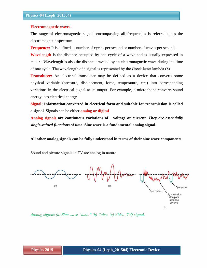
Analog signals are continuous variations of voltage or current. They are essentially
single-valued functions of time. Sine wave is a fundamental analog signal.
All other analog signals can be fully understood in terms of their sine wave components.
Sound and picture signals in TV are analog in nature.
Analog signals (a) Sine wave “tone.” (b) Voice. (c) Video (TV) signal.
Physics 2019 Physics-04 (Leph_201504) Electronic Device
Physics-04 (Leph_201504)
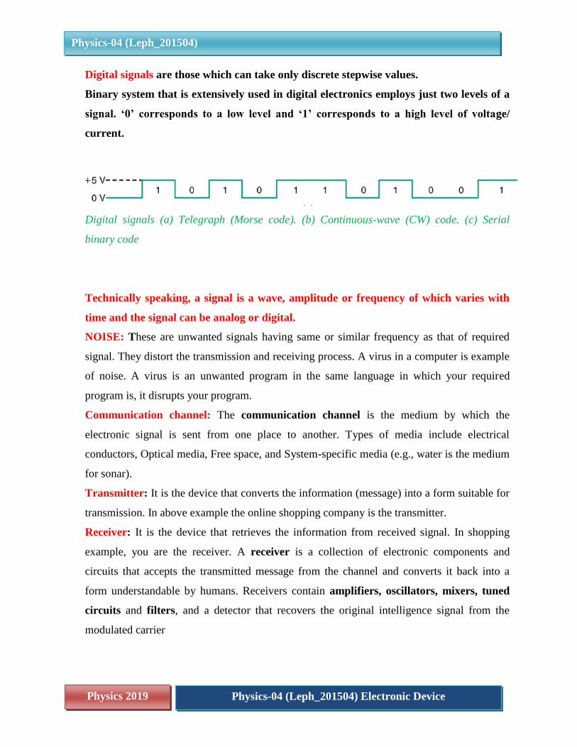
Digital signals are those which can take only discrete stepwise values.
Binary system that is extensively used in digital electronics employs just two levels of a
signal. ‘0’ corresponds to a low level and ‘1’ corresponds to a high level of voltage/
current.
Digital signals (a) Telegraph (Morse code). (b) Continuous-wave (CW) code. (c) Serial
binary code
Technically speaking, a signal is a wave, amplitude or frequency of which varies with
time and the signal can be analog or digital.
NOISE: These are unwanted signals having same or similar frequency as that of required
signal. They distort the transmission and receiving process. A virus in a computer is example
of noise. A virus is an unwanted program in the same language in which your required
program is, it disrupts your program.
Communication channel: The communication channel is the medium by which the
electronic signal is sent from one place to another. Types of media include electrical
conductors, Optical media, Free space, and System-specific media (e.g., water is the medium
for sonar).
Transmitter: It is the device that converts the information (message) into a form suitable for
transmission. In above example the online shopping company is the transmitter.
Receiver: It is the device that retrieves the information from received signal. In shopping
example, you are the receiver. A receiver is a collection of electronic components and
circuits that accepts the transmitted message from the channel and converts it back into a
form understandable by humans. Receivers contain amplifiers, oscillators, mixers, tuned
circuits and filters, and a detector that recovers the original intelligence signal from the
modulated carrier
Physics 2019 Physics-04 (Leph_201504) Electronic Device
Physics-04 (Leph_201504)
Transceivers: A transceiver is an electronic unit that incorporates circuits that both send
and receive signals. Examples are: Telephones, Fax machines, radios, Cell, mobile phones,
computers.
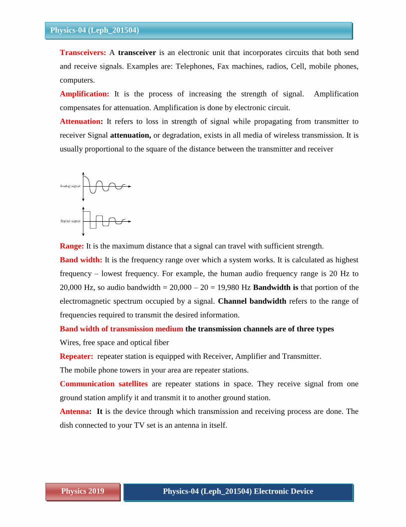
Amplification: It is the process of increasing the strength of signal. Amplification
compensates for attenuation. Amplification is done by electronic circuit.
Attenuation: It refers to loss in strength of signal while propagating from transmitter to
receiver Signal attenuation, or degradation, exists in all media of wireless transmission. It is
usually proportional to the square of the distance between the transmitter and receiver
Range: It is the maximum distance that a signal can travel with sufficient strength.
Band width: It is the frequency range over which a system works. It is calculated as highest
frequency – lowest frequency. For example, the human audio frequency range is 20 Hz to
20,000 Hz, so audio bandwidth = 20,000 – 20 = 19,980 Hz Bandwidth is that portion of the
electromagnetic spectrum occupied by a signal. Channel bandwidth refers to the range of
frequencies required to transmit the desired information.
Band width of transmission medium the transmission channels are of three types
Wires, free space and optical fiber
Repeater: repeater station is equipped with Receiver, Amplifier and Transmitter.
The mobile phone towers in your area are repeater stations.
Communication satellites are repeater stations in space. They receive signal from one
ground station amplify it and transmit it to another ground station.
Antenna: It is the device through which transmission and receiving process are done. The
dish connected to your TV set is an antenna in itself.
Physics 2019 Physics-04 (Leph_201504) Electronic Device
Physics-04 (Leph_201504)
Carrier wave: A carrier is a high frequency signal that is modulated by audio, video, or
data. A radio-frequency (RF) wave is an electromagnetic signal that is able to travel long
distances through space
Broadcasting is the distribution of audio or video content to a dispersed audience via any
electronic mass communications medium, but typically one using the electromagnetic
spectrum (radio waves), in a one-to-many model
Mode of em wave propagation: em waves travel in three ways through the atmosphere,
ground wave, sky wave and space wave.
The modulated wave is a combination of message signal and carrier wave.
A sinusoidal carrier wave can be represented as
𝒄(𝒕) = 𝑨𝒄 𝐬𝐢𝐧(𝝎𝒄𝒕 + 𝜽)
Where,
c(t) is the signal strength (voltage or current),
Ac is the amplitude,
ωc ( = 2πfc) is the angular frequency
and
θ is the initial phase of the carrier wave.
During the process of modulation, any of the three parameters,
Viz Ac, ωc and θ, of the carrier wave can be controlled by the message or information signal.
This results in three types of modulation:
(i) Amplitude modulation (AM),
(ii) Frequency modulation (FM)
(iii) Phase modulation (PM),
4. INTRODUCTION
We have so far in this unit, studied the most basic meaning of communication which is
transmission of information from one point to another. The setup used for the purpose is
called communication system. The purpose of a communication system is, therefore, is to
transmit information from a source, located at one place, and to a receiver located at another
point. The system primarily has three major parts
Physics 2019 Physics-04 (Leph_201504) Electronic Device
Physics-04 (Leph_201504)
1) Transmitter which is a combination of audio video, data converter to electrical analog or
digital signal (transducers) modulators to convert the base band signal to AM FM or PM
modulated electrical signal. This is done in case wireless transmission is required.
2) Communication channel this could be wired or wireless.
3) Receiver contains transducers to tune on the electromagnetic waves and retrieve the
baseband signal
We must realise here that we are only studying the processes of communication system
without actually going into circuits and their appropriate designs. There is a lot of technical
design to amplify and modulate signals that reach us from a source. Example consider a
mobile phone, we dial antenna digit number and out of the entire mobile phones in use across
the world only the desired one is connected or when we google a map the search engine
places the options before us on the screen.
In this module we will now attempt to understand amplitude modulation
The first amplitude modulated signal was transmitted in 1901 by a Canadian engineer named
Reginald Fessenden. He took a continuous spark transmission and placed a carbon
microphone in the antenna lead.
The sound waves impacting on the microphone varied its resistance and in turn this varied
the intensity of the transmission. Although very crude, signals were audible over a distance
of a few hundred metres, although there was a rasping sound caused by the spark.
With the introduction of continuous sine wave signals, transmissions improved significantly,
and AM soon became the standard for voice transmissions. Nowadays, amplitude
modulation, AM is used for audio broadcasting on the long medium and short wave bands,
and for two way radio communication at VHF for aircraft.
However as there now are more efficient and convenient methods of modulating a signal, its
use is declining, although it will still be very many years before it is no longer used.
5. AMPLITUDE MODULATION
In amplitude modulation the amplitude of carrier wave is changed according to the message
or information signal. Here we explain the process of amplitude modulation.
Physics 2019 Physics-04 (Leph_201504) Electronic Device
Physics-04 (Leph_201504)
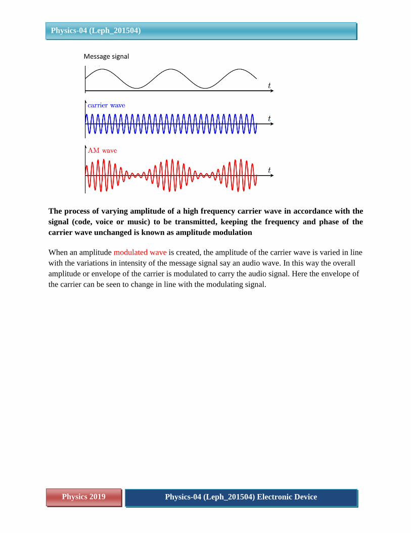
The process of varying amplitude of a high frequency carrier wave in accordance with the
signal (code, voice or music) to be transmitted, keeping the frequency and phase of the
carrier wave unchanged is known as amplitude modulation
When an amplitude modulated wave is created, the amplitude of the carrier wave is varied in line
with the variations in intensity of the message signal say an audio wave. In this way the overall
amplitude or envelope of the carrier is modulated to carry the audio signal. Here the envelope of
the carrier can be seen to change in line with the modulating signal.
Message signal
Physics 2019 Physics-04 (Leph_201504) Electronic Device
Physics-04 (Leph_201504)
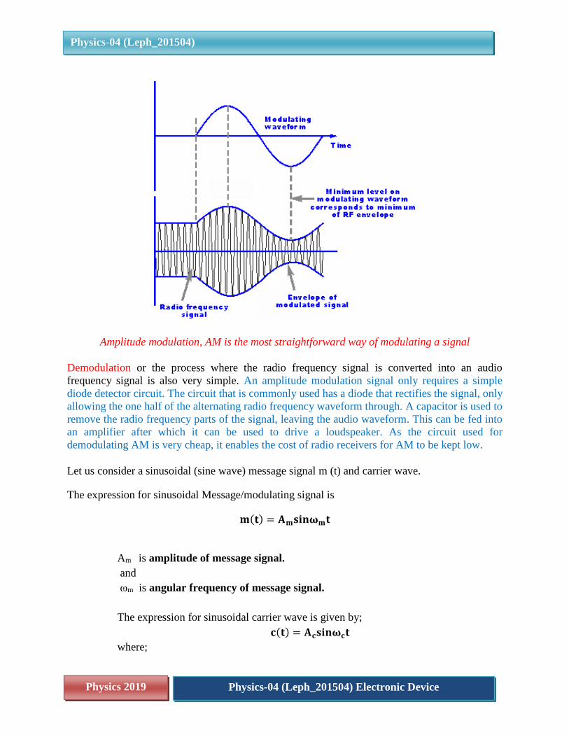
Amplitude modulation, AM is the most straightforward way of modulating a signal
Demodulation or the process where the radio frequency signal is converted into an audio
frequency signal is also very simple. An amplitude modulation signal only requires a simple
diode detector circuit. The circuit that is commonly used has a diode that rectifies the signal, only
allowing the one half of the alternating radio frequency waveform through. A capacitor is used to
remove the radio frequency parts of the signal, leaving the audio waveform. This can be fed into
an amplifier after which it can be used to drive a loudspeaker. As the circuit used for
demodulating AM is very cheap, it enables the cost of radio receivers for AM to be kept low.
Let us consider a sinusoidal (sine wave) message signal m (t) and carrier wave.
The expression for sinusoidal Message/modulating signal is
𝐦(𝐭) = 𝐀𝐦𝐬𝐢𝐧𝛚𝐦𝐭
Am is amplitude of message signal.
and
ωm is angular frequency of message signal.
The expression for sinusoidal carrier wave is given by;
𝐜(𝐭) = 𝐀𝐜𝐬𝐢𝐧𝛚𝐜𝐭
where;
Physics 2019 Physics-04 (Leph_201504) Electronic Device
Physics-04 (Leph_201504)
Ac is amplitude of carrier wave
ωc is angular frequency of carrier wave.
After modulation a new wave is formed called modulated wave.
The modulated wave is a combination of message signal and carrier wave.
The expression for modulated wave is given by,
𝐦(𝐭) = 𝐀𝐦𝐬𝐢𝐧𝛚𝐦𝐭 + 𝐜(𝐭) = 𝐀𝐜𝐬𝐢𝐧𝛚𝐜𝐭
By superposition the two signals are combined
𝐂𝐦(𝐭) = (𝐀𝐜 + 𝐀𝐦𝐬𝐢𝐧𝛚𝐦𝐭)𝐬𝐢𝐧𝛚𝐜𝐭
= 𝐀 (𝟏 +𝐀𝐦
𝐀𝐜𝐬𝐢𝐧𝛚𝐜𝐭) 𝐬𝐢𝐧𝛚𝐜𝐭
Note that modulated signal contains the message signal.
(Ac + Am sin ωm t) is amplitude of modulated wave and ωc is frequency of modulated wave.
Also note that amplitude of modulated wave is changing with time “t” and frequency of
modulated wave is same as of carrier.
It is because we have changed only the amplitude of carrier not it’s frequency.so the
modulated signal contains the message signal.
We can write the above equation as
𝑪𝒎(𝒕) = 𝐀 (𝟏 +𝐀𝐦
𝐀𝐜𝐬𝐢𝐧𝛚𝐜𝐭) 𝐬𝐢𝐧𝛚𝐜𝐭
𝛍 =𝐀𝐦
𝐀𝐜 𝐜𝐚𝐥𝐥𝐞𝐝 𝐭𝐡𝐞 𝐦𝐨𝐝𝐮𝐥𝐚𝐭𝐢𝐧𝐠 𝐢𝐧𝐝𝐞𝐱
In practice μ is kept ≤ 1 to avoid distortion, physically it means that the amplitude of baseband
or message signal is kept slightly less than the amplitude of carrier wave.
Using trigonometric identity
𝑠𝑖𝑛𝐴𝑠𝑖𝑛𝐵 =1
2[𝑐𝑜𝑠(𝐴 − 𝐵) − 𝑐𝑜𝑠(𝐴 + 𝐵)]
Physics 2019 Physics-04 (Leph_201504) Electronic Device
Physics-04 (Leph_201504)
𝐂𝐦(𝐭) = 𝐀𝐜𝐬𝐢𝐧𝛚𝐜𝐭 +𝛍𝐀𝐜
𝟐𝐜𝐨𝐬(𝛚𝐜 − 𝛚𝐦)𝐭 −
𝛍𝐀𝐜
𝟐𝐜𝐨𝐬(𝛚𝐜 + 𝛚𝐦)𝐭
Here (𝛚𝐜 − 𝛚𝐦)and(𝛚𝐜 + 𝛚𝐦) are called side band frequencies.
(𝛚𝐜 − 𝛚𝐦)= Lower side band frequency
(𝛚𝐜 + 𝛚𝐦)= Upper side band frequency
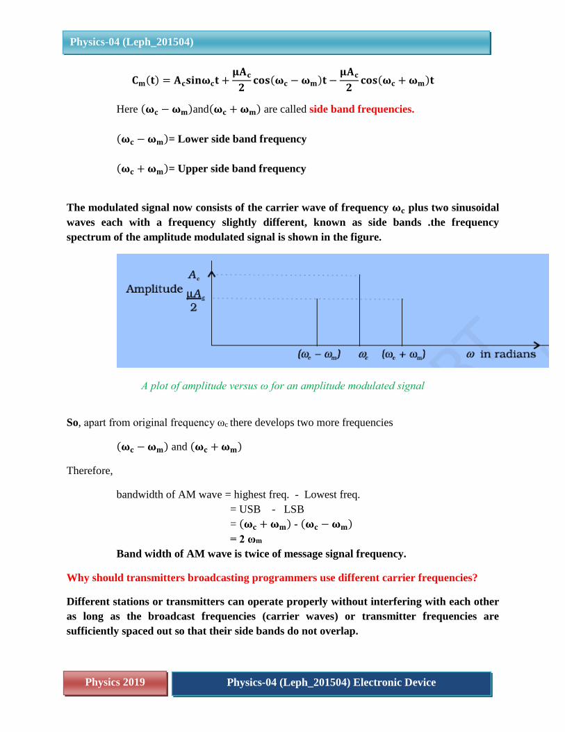
The modulated signal now consists of the carrier wave of frequency 𝛚𝐜 plus two sinusoidal
waves each with a frequency slightly different, known as side bands .the frequency
spectrum of the amplitude modulated signal is shown in the figure.
A plot of amplitude versus ω for an amplitude modulated signal
So, apart from original frequency ωc there develops two more frequencies
(𝛚𝐜 − 𝛚𝐦) and (𝛚𝐜 + 𝛚𝐦)
Therefore,
bandwidth of AM wave = highest freq. - Lowest freq.
= USB - LSB
= (𝛚𝐜 + 𝛚𝐦) - (𝛚𝐜 − 𝛚𝐦)
= 2 ωm
Band width of AM wave is twice of message signal frequency.
Why should transmitters broadcasting programmers use different carrier frequencies?
Different stations or transmitters can operate properly without interfering with each other
as long as the broadcast frequencies (carrier waves) or transmitter frequencies are
sufficiently spaced out so that their side bands do not overlap.
Physics 2019 Physics-04 (Leph_201504) Electronic Device
Physics-04 (Leph_201504)
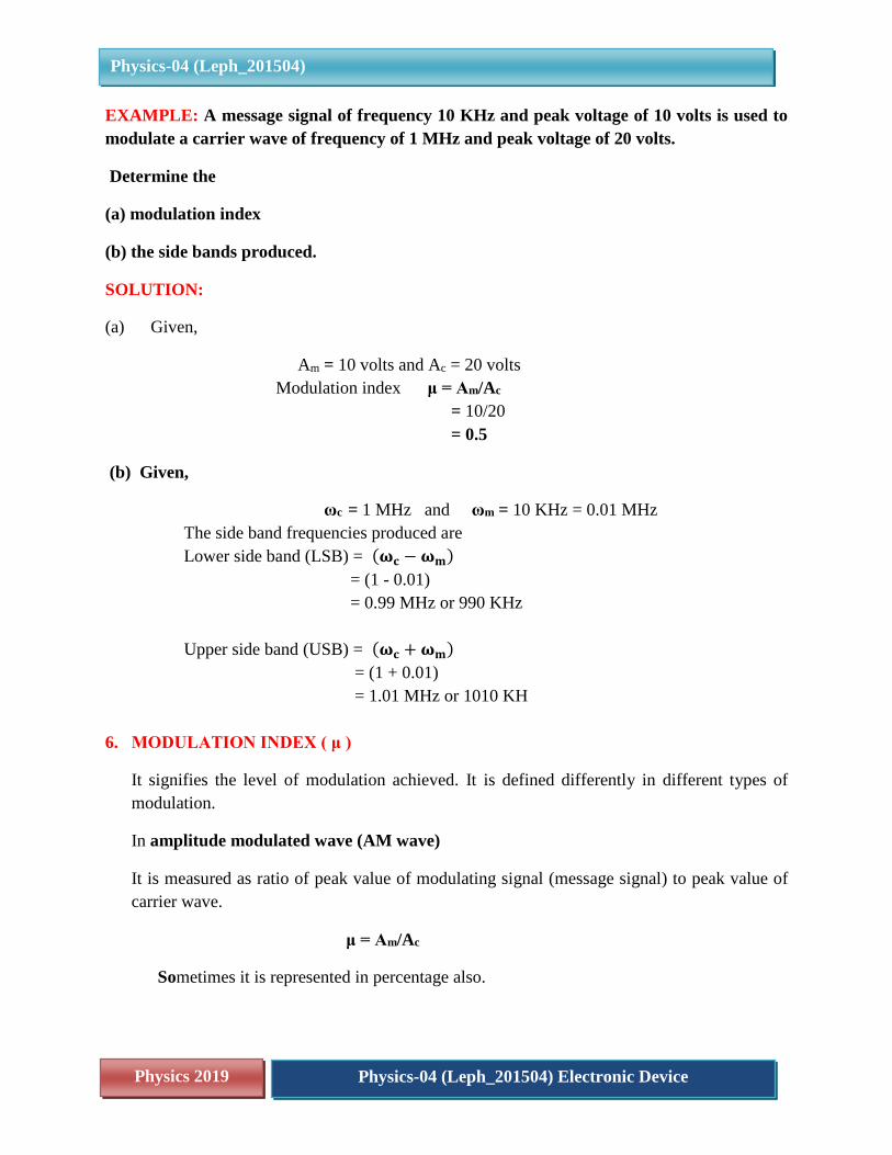
EXAMPLE: A message signal of frequency 10 KHz and peak voltage of 10 volts is used to
modulate a carrier wave of frequency of 1 MHz and peak voltage of 20 volts.
Determine the
(a) modulation index
(b) the side bands produced.
SOLUTION:
(a) Given,
Am = 10 volts and Ac = 20 volts
Modulation index μ = Am/Ac
= 10/20
= 0.5
(b) Given,
ωc = 1 MHz and ωm = 10 KHz = 0.01 MHz
The side band frequencies produced are
Lower side band (LSB) = (𝛚𝐜 − 𝛚𝐦)
= (1 - 0.01)
= 0.99 MHz or 990 KHz
Upper side band (USB) = (𝛚𝐜 + 𝛚𝐦)
= (1 + 0.01)
= 1.01 MHz or 1010 KH
6. MODULATION INDEX ( μ )
It signifies the level of modulation achieved. It is defined differently in different types of
modulation.
In amplitude modulated wave (AM wave)
It is measured as ratio of peak value of modulating signal (message signal) to peak value of
carrier wave.
μ = Am/Ac
Sometimes it is represented in percentage also.
Physics 2019 Physics-04 (Leph_201504) Electronic Device
Physics-04 (Leph_201504)
If value of μ = 50% or 0.5 means carrier wave is modulated by 50% means the amplitude of
carrier has varied by 50% .
If value of μ = 100% or 1 means carrier wave is modulated by 100% means the amplitude of
carrier has varied by 100% . In this condition, the amplitude of modulated wave at certain places
will becomes zero.
We cannot increase value of μ beyond 1 then amplitude of modulated wave will become
negative and then the noise increases . Hence value of μ is kept less than equal to 1 ( μ ≤ 1).
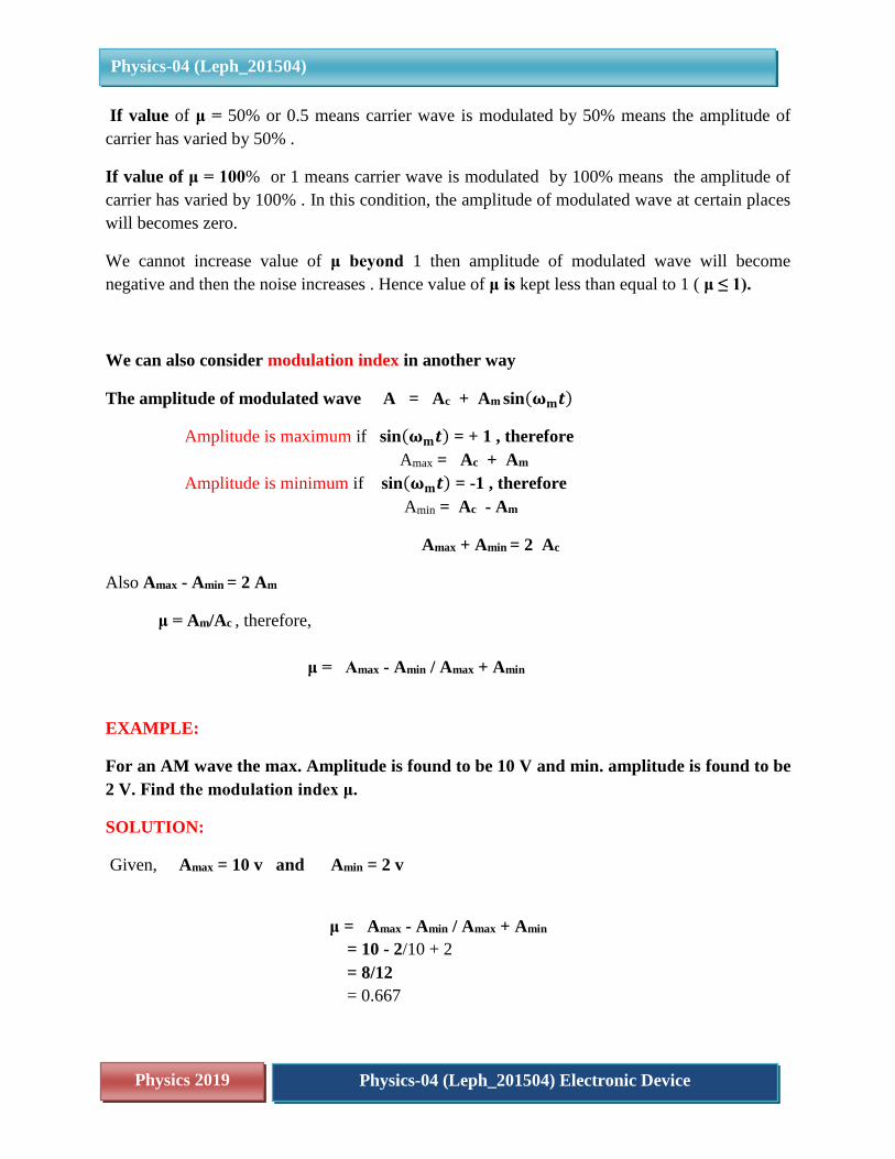
We can also consider modulation index in another way
The amplitude of modulated wave A = Ac + Am sin(𝛚𝐦𝒕)
Amplitude is maximum if sin(𝛚𝐦𝒕) = + 1 , therefore
Amax = Ac + Am
Amplitude is minimum if sin(𝛚𝐦𝒕) = -1 , therefore
Amin = Ac - Am
Amax + Amin = 2 Ac
Also Amax - Amin = 2 Am
μ = Am/Ac , therefore,
μ = Amax - Amin / Amax + Amin
EXAMPLE:
For an AM wave the max. Amplitude is found to be 10 V and min. amplitude is found to be
2 V. Find the modulation index μ.
SOLUTION:
Given, Amax = 10 v and Amin = 2 v
μ = Amax - Amin / Amax + Amin
= 10 - 2/10 + 2
= 8/12
= 0.667
Physics 2019 Physics-04 (Leph_201504) Electronic Device
Physics-04 (Leph_201504)
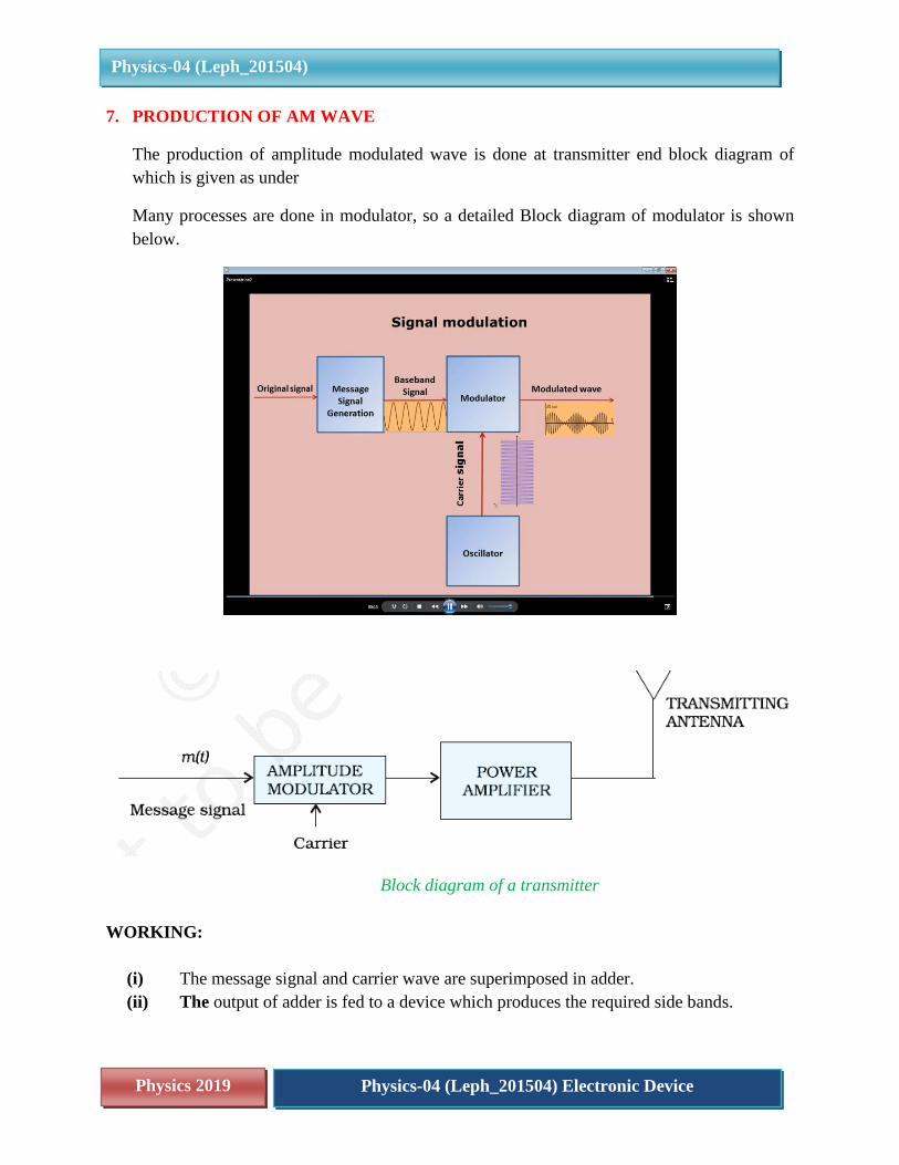
7. PRODUCTION OF AM WAVE
The production of amplitude modulated wave is done at transmitter end block diagram of
which is given as under
Many processes are done in modulator, so a detailed Block diagram of modulator is shown
below.
Block diagram of a transmitter
WORKING:
(i) The message signal and carrier wave are superimposed in adder.
(ii) The output of adder is fed to a device which produces the required side bands.
Physics 2019 Physics-04 (Leph_201504) Electronic Device
Physics-04 (Leph_201504)
(iii) The output of the device is sent to band pass filter centered at ωc. This filter allows
the required frequencies of side bands and carrier wave and rejects the other unwanted
frequencies.
(iv) The filtered wave is the required AM wave which is amplified in power amplifier of
transmitter and transmitted through transmitting antenna.
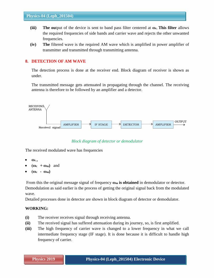
8. DETECTION OF AM WAVE
The detection process is done at the receiver end. Block diagram of receiver is shown as
under.
The transmitted message gets attenuated in propagating through the channel. The receiving
antenna is therefore to be followed by an amplifier and a detector.
Block diagram of detector or demodulator
The received modulated wave has frequencies
ωc ,
(ωc + ωm) and
(ωc - ωm)
From this the original message signal of frequency ωm is obtained in demodulator or detector.
Demodulation as said earlier is the process of getting the original signal back from the modulated
wave.
Detailed processes done in detector are shown in block diagram of detector or demodulator.
WORKING:
(i) The receiver receives signal through receiving antenna.
(ii) The received signal has suffered attenuation during its journey, so, is first amplified.
(iii) The high frequency of carrier wave is changed to a lower frequency in what we call
intermediate frequency stage (IF stage). It is done because it is difficult to handle high
frequency of carrier.
Physics 2019 Physics-04 (Leph_201504) Electronic Device
Physics-04 (Leph_201504)
(iv) Then received signal is sent to detector for actual processing.
(v) In detector, the AM wave is first passed through half wave rectifier to reject the lower
envelope.
(vi) The rectified wave is now sent to envelope detector.
(vii) The envelope picks the low frequency envelope and rejects the high frequency part.
(viii) This envelope is our original message m(t). It is again amplified and sent to user.
9. APPLICATIONS OF AM WAVE
Amplitude modulation is oldest method used to transmit voice by radio broadcast. In marine
and aircraft navigation also AM waves are used because they can travel longer distance.
These waves are used in
Citizen Band radio (CB Radio). CB radio is a club of people around the globe. It is also
called amateur radio.
Broadcast transmissions: AM is still widely used for broadcasting on the long,
medium and short wave bands. It is simple to demodulate and this means that radio
receivers capable of demodulating amplitude modulation are cheap and simple to
manufacture.
Used in Navy and Aviation for communications as AM signals can travel longer
distances.
Used by traffic , mela police for messaging
Air band radio: VHF transmissions for many airborne applications still use AM.. It is
used for ground to air radio communications as well as two way radio links for ground
staff as well.
HF Radio links: Amplitude modulation in the form of single sideband is still used for
HF radio links. Using a lower bandwidth and providing more effective use of the
transmitted power this form of modulation is still used for many point to point HF links.
Short range wireless links: AM is widely used for the transmission of data in everything
from short range wireless links such as Wi-Fi to cellular telecommunications and much
more.
These form some of the main uses of amplitude modulation. However in its basic form,
this form of modulation is being sued less as a result of its inefficient use of both
spectrum and power.
While amplitude modulation is one of the simplest and easiest forms of signal modulation to
implement, it is not the most efficient in terms of spectrum efficiency and power usage. As a
Physics 2019 Physics-04 (Leph_201504) Electronic Device
Physics-04 (Leph_201504)
result, the use of amplitude modulation is falling in preference to other modes such as
frequency modulation, and a variety of digital modulation formats.
Yet despite this decrease, amplitude modulation is in such widespread use, especially for
broadcasting, and many amplitude modulation signals can still be heard on the various long,
medium and short wavebands where they will undoubtedly be heard for many years to come.
Why do we not use AM for transmitting music?
Adding of noise for amplitude modulated signal will be more when compared to frequency
modulated signals. Data loss is also more in amplitude modulation due to noise addition.
Demodulators cannot reproduce the exact music or modulating signal due to noise.
Why more power is needed to transmit AM signals?
More power is required during modulation because Amplitude modulated signal frequency
should be double than modulating signal or message signal frequency. Due to this reason
more power is required for amplitude modulation.
Why is higher level of noise produced in AM signal transmission?
Sidebands are also transmitted during the transmission of carrier signal. More chances of
getting different signal interfaces and adding of noise is more when compared to frequency
modulation. Noise addition and signal interferences are less for frequency modulation. That
is why Amplitude modulation is not used for broadcasting songs or music.
10. ADVANTAGES AND DISADVANTAGES OF AMPLITUDE MODULATION
Advantages the modulation requires simple modulator circuits; they are cheap and so are
commercially used for audio and speech transmission. The hand held toy radio sets use AM
circuits demodulation can be easily done with low cost circuits.
The poor performance due to noise is their greatest disadvantage .they require greater power,
since the band width is twice that of the signal the AM devices are not very efficient
TRY THESE
(i) Distinguish between modulation and amplitude modulation.
(ii) Draw block diagram of transmitter.
(iii) Draw block diagram of modulator.
(iv) Draw block diagram of receiver.
(v) What is the function of IF stage in receiver?
(vi) Explain in brief the working of detector.
Physics 2019 Physics-04 (Leph_201504) Electronic Device
Physics-04 (Leph_201504)
11. SUMMARY
Modulation is the process of superimposing a low frequency signal over a high frequency
wave called carrier wave.
After modulation a new wave is formed called modulated wave. The modulated wave is a
combination of message signal and carrier wave.
There are 3 types of modulation
Amplitude modulation (AM)
Frequency modulation (FM) and
Phase modulation (PM)
The process of varying amplitude of a high frequency carrier wave in accordance with the
signal ( code, voice or music ) to be transmitted , keeping the frequency and phase of the
carrier wave unchanged is known as amplitude modulation
In amplitude modulation the amplitude of carrier wave is changed according to the message
or information signal.
The expression for amplitude modulated wave is given by,
Cm(t) = ( Ac + Am sinωmt ) sinωct
= Ac ( 1 + Am/ Ac sinωmt ) sinωct
The modulated signal contains the message signal.
( Ac + Am sin ωm t ) is amplitude of modulated wave and ωc is frequency of modulated
wave. The amplitude of modulated wave changes with time “t” and frequency of modulated
wave is same as of carrier. It is because we only change the amplitude of carrier wave and
not it’s frequency.
An amplitude modulated wave has frequencies (ωc - ωm) , ωc and (ωc + ωm) . (ωc
- ωm) = Lower side band frequency
(ωc + ωm) = Upper side band frequency.
Bandwidth of AM wave = highest freq. - Lowest freq.
= USB - LSB
= (ωc + ωm) - (ωc - ωm)
= 2 ωm
Band width of AM wave is twice of message signal frequency.
Different stations or transmitters can operate properly without interfering with each other
as long as the broadcast frequencies (carrier waves ) or transmitter frequencies should be
sufficiently spaced out so that their side bands do not overlap.
Physics 2019 Physics-04 (Leph_201504) Electronic Device
Physics-04 (Leph_201504)
μ = Am/Ac is called modulation index in practice μ ≤ 1 to avoid distortion of signal.
If value of μ = 100% or 1 means carrier wave is modulated by 100% means the amplitude of
carrier has varied by 100% . In this condition, the amplitude of modulated wave at certain
places will becomes zero.
We cannot increase value of μ beyond 1 then amplitude of modulated wave will become
negative and chances of introduction of noise increases a lot. Hence value of μ is kept less
than equal to 1 ( μ ≤ 1).
The electrical /electronic circuits used for amplitude modulated waves, for their transmission
and retrieval are cheap and relatively simple.
AM waves are used by amateur radio designers; police patrol work, marine and aircraft
navigation because they can travel longer distance as compared to wired or cabled
transmissions.