Physically Unclonable Functions:Constructions, Properties ... · were invariably present. e of the...
260
Arenberg Doctoral School of Science, Engineering & Technology Faculty of Engineering Department of Electrical Engineering (ESAT) Physically Unclonable Functions: Constructions, Properties and Applications Roel MAES Dissertation presented in partial fulfillment of the requirements for the degree of Doctor in Engineering August 2012
Transcript of Physically Unclonable Functions:Constructions, Properties ... · were invariably present. e of the...

Arenberg Doctoral School of Science, Engineering & Technology
Faculty of Engineering
Department of Electrical Engineering (ESAT)
Physically Unclonable Functions:
Constructions, Properties and Applications
Roel MAES
Dissertation presented in partial
fulfillment of the requirements for
the degree of Doctor
in Engineering
August 2012

Physically Unclonable Functions:
Constructions, Properties and Applications
Roel MAES
Jury:Prof. dr. ir. Ann Haegemans, chairProf. dr. ir. Ingrid Verbauwhede, promotorProf. dr. ir. Bart PreneelProf. dr. ir. Patrick WambacqProf. dr. ing. Ahmad-Reza Sadeghi
(Technische Universität Darmstadt, Germany)Dr. Pim Tuyls
(Intrinsic-ID B.V., the Netherlands)
Dissertation presented in partialfulfillment of the requirements forthe degree of Doctorin Engineering
August 2012

© Katholieke Universiteit Leuven – Faculty of EngineeringKasteelpark Arenberg 10 box 2446, B-3001 Heverlee (Belgium)
Alle rechten voorbehouden. Niets uit deze uitgave mag worden vermenigvuldigden/of openbaar gemaakt worden door middel van druk, fotocopie, microfilm,elektronisch of op welke andere wijze ook zonder voorafgaande schriftelijketoestemming van de uitgever.
All rights reserved. No part of the publication may be reproduced in any formby print, photoprint, microfilm or any other means without written permissionfrom the publisher.
D/2012/7515/95ISBN 978-94-6018-561-8

Acknowledgements
procrastination, n. /pr@(U)�krast1"neISn/1. The action or habit of postponing or putting
something off; delay, dilatoriness. Often withthe sense of deferring through indecision, whenearly action would have been preferable.
2. The postponing or deferring of something.
The Oxford English Dictionary
I have put off writing this paragraph to the very last moment before printingthis book, presumably because it is the hardest and undoubtedly the most readpart of this lengthy thesis. My versioning system tells me that it has been fourmonths since I committed the first sentence of this manuscript, and in totalit has been almost five years since I started the research which led to it. Andwhat a five years it have been; filled with challenge and wonder, hard workand fun, joy and frustration, collaboration and friendship. I want to spend afew words to thank all the people who have played a role in this remarkableadventure which is the pursuit of a Ph.D. degree.
Before all others, I am grateful to my promotor Prof. Ingrid Verbauwhede, forthe opportunities she has created for me, for her advise on matters great andsmall, and for trusting me to find my own way. I am also much indebted toDr. Pim Tuyls for introducing me to the exciting topic of this thesis and guidingme through my first couple of years as a young researcher. In addition, I wantto thank my other jury members for their combined effort in reviewing thistext, the KU Leuven for offering such an inspiring academic environment, andthe Agency for Innovation by Science and Technology (IWT) for funding themajor part of my research.
Being a researcher is far from a solitary occupation, and I have had the pleasureand privilege of meeting and collaborating with many of my peers worldwide.
i

ii ACKNOWLEDGEMENTS
The very last section in this book would be considerably shorter without thecontribution and guidance of all my appreciated coauthors. A special thanksgoes out to the partners of the European UNIQUE project, and the peoplebehind them, with whom it was always a pleasure to meet and discuss things,and from whom I have learned a lot. I also greatly enjoyed the opportunitiesto get a taste of the life as a researcher in industry, through internships atPhilips and Intel; both were extremely challenging experiences which have hada significant positive impact on me.
It is hard to overestimate my gratitude for being able to work in an atmosphereas vibrant, yet warm and friendly as the COSIC research group. Over the yearsI have seen people come and go, but the helpfulness, sociability and plain funwere invariably present. One of the many special people responsible for this isPéla Noé, COSIC’s secretary and so much more, but I am grateful to all mycolleagues who make COSIC such an enjoyable place to work.
Een dankjewel uit de grond van mijn hart is voor mijn familie die altijd inmij is blijven geloven: voor mijn ouders die mij ongelooflijke kansen hebbengeboden, mij ook stimuleerden om deze te grijpen en me uiteindelijk de vrijheidgaven om er ten volste voor te gaan; voor mijn broer en zus voor wie ik nietaltijd de makkelijkste broer was, maar op wie ik altijd kan rekenen als ik zenodig heb; voor mijn grootouders die mij onvoorwaardelijk graag zien; voormijn schoonouders en -broers, voor het warme welkom in hun familie en devele ijsjes tijdens het schrijven van deze tekst. Ook een dikke merci aan mijnvrienden, om mij op tijd en stond met mijn voeten op de grond te zetten en mete laten meegenieten van de echte belangrijke dingen in het leven. Mijn laatstewoord van dank is voor mijn lieve vrouw Sofie, omdat ze mij al jaren verdraagten steunt, helpt en aanvult, begrijpt en liefheeft. Zonder haar was ik maar halfde man die ik vandaag ben.
Roel MaesAugust 2012
Abstract
Physically unclonable functions or PUFs are innovative physical security primi-tives which produce unclonable and inherent instance-specific measurements ofphysical objects; PUFs are in many ways the inanimate equivalent of biometricsfor human beings. Since they are able to securely generate and store secrets,PUFs allow to bootstrap the physical implementation of an information securitysystem. In this thesis, we discuss PUFs in all their facets: the multitude of theirphysical constructions, the algorithmic and physical properties which describethem, and the techniques required to deploy them in security applications. Wepresent our contributions on each of these aspects.
We first give an unprecedented extensive overview and classification of PUFconstructions, with a focus on intrinsic PUFs. We identify significantsubclasses, implementation properties and general design techniques used toamplify sub-microscopic physical distinctions into observable digital responsevectors. We list the useful properties attributed to PUFs and capture them indescriptive yet clear definitions. Through an elaborate comparative analysis,we distinguish truly PUF-defining properties from nice-to-have but not strictlyrequired qualities. Additionally, we describe a formal framework for deployingPUFs and similar physical primitives in cryptographic reductions.
In order to objectively compare the quality of different PUF constructions, wecontributed to the development of a silicon test platform carrying six differentintrinsic PUF structures. Based on experimental data from 192 distinct testdevices, including measurements at temperature and supply voltage cornercases, we assess the reliability, the uniqueness and the unpredictability of eachof these constructions and summarize them in concise yet meaningful statistics.
Their instance-specific and unclonable nature enables to use PUFs as entityidentifiers. In combination with appropriate processing algorithms, theycan even authenticate entities and securely generate and store secrets. Wepresent new techniques to achieve PUF-based entity identification, entity
iii

iv ABSTRACT
authentication, and secure key generation. We additionally propose practicaldesigns implementing these techniques, and derive and calculate meaningfulmeasures for assessing the performance of different PUF constructions in theseapplications based on the quality of their response statistics. Finally, as aproof of concept, we present a fully functional prototype implementation ofa PUF-based cryptographic key generator, demonstrating the full benefit ofusing PUFs and the efficiency of the introduced processing techniques.
Beknopte samenvatting
Fysisch onkloonbare functies of PUF’s (Physically Unclonable Functions)zijn innovatieve fysische beveiligingsprimitieven die onkloonbare en inherenteinstantiespecifieke metingen van een fysisch object produceren; in veelopzichten zijn PUF’s het materiële equivalent van biometrische eigenschappenvoor personen. Doordat ze op een veilige manier geheimen kunnen genererenen onthouden, zijn PUF’s in staat om de grondslag te leggen voor de fysischeimplementatie van informatiebeveiligingssystemen. In deze verhandelingbespreken we PUF’s in al hun facetten: de verscheidenheid van hunfysische constructies, de algoritmische en fysische eigenschappen waardoorze worden beschreven, en de benodigde technieken om ze te gebruiken inbeveiligingstoepassingen. We presenteren onze bijdragen aan elk van dezeaspecten.
Eerst geven we een uitvoerig overzicht zonder voorgaande en een classificatievan PUF-constructies, met de focus op intrinsieke PUF’s. We identificerenbelangrijke subklassen, implementatie-eigenschappen en algemene ontwerptech-nieken die gebruikt worden om submicroscopische fysische verschillen tevergroten tot waarneembare digitale responsvectoren. We lijsten de nuttigeeigenschappen op die worden toegeschreven aan PUF’s en vatten ze in beschri-jvende maar duidelijke definities. Op basis van een uitgebreide vergelijkendeanalyse onderscheiden we de werkelijk PUF-definiërende eigenschappen vanandere nuttige maar niet noodzakelijke kwaliteiten. Daarnaast beschrijvenwe een strikt formeel raamwerk voor het inzetten van PUF’s en vergelijkbarefysische primitieven in cryptografische afleidingen.
Om de kwaliteit van verschillende PUF-constructies op een objectieve manierte vergelijken hebben we bijgedragen aan de ontwikkeling van een siliciumtestplatform dat zes verschillende intrinsieke PUF-structuren bevat. Gebaseerdop experimentele data verkregen van 192 individuele testchips, inclusiefmetingen onder de uiterste temperatuur- en voedingsspanningsconditities,hebben we de betrouwbaarheid, de uniciteit en de onvoorspelbaarheid van elk
v
vi BEKNOPTE SAMENVATTING
van deze constructies afgetoetst en samengevat in bevattelijke maar zinvollestatistieken.
Hun instantiespecifieke en onkloonbare aard laat toe om PUF’s te gebruikenvoor entiteitsidentificatie. In combinatie met gepaste verwerkingsalgoritmeskunnen ze zelfs entiteiten authentiseren en op een veilige manier geheimengenereren en opslaan. We presenteren nieuwe technieken om PUF-gebaseerdeentiteitsidentificatie en -authenticatie, en veilige sleutelgeneratie mogelijk temaken. We stellen bovendien praktische ontwerpen voor om deze techniekente implementeren. We bepalen en berekenen betekenisvolle maatstaven om deperformantie van de verschillende PUF-constructies in deze toepassingen af tetoetsen aan de hand van hun responsstatistieken. Uiteindelijk presenteren weeen volledige werkzaam prototype van een PUF-gebaseerde sleutelgenerator alseen proof-of-concept-implementatie, om de volledige voordelen van het gebruikvan PUF’s te demonstreren, alsook om de efficiëntie van de geïntroduceerdeverwerkingstechnieken aan te tonen.
Contents
Abstract iii
Beknopte samenvatting v
Contents vii
List of Figures xv
List of Tables xvii
List of Abbreviations xix
1 Introduction and Preview 1
1.1 Introduction . . . . . . . . . . . . . . . . . . . . . . . . . . . . . . 1
1.1.1 Trust and Security in a Modern World . . . . . . . . . . . 1
1.1.2 Information Security and Cryptology . . . . . . . . . . . 3
1.1.3 Physical Security and Roots of Trust . . . . . . . . . . . 6
1.2 Preview . . . . . . . . . . . . . . . . . . . . . . . . . . . . . . . 8
1.2.1 Introducing Physically Unclonable Functions . . . . . . 8
1.2.2 Thesis Outline and Contributions . . . . . . . . . . . . . 10
vii
viii CONTENTS
2 Physically Unclonable Functions: Concept and Constructions 13
2.1 Introduction . . . . . . . . . . . . . . . . . . . . . . . . . . . . . 13
2.1.1 The PUF Concept . . . . . . . . . . . . . . . . . . . . . 13
2.1.2 Chapter Goals . . . . . . . . . . . . . . . . . . . . . . . 15
2.1.3 Chapter Overview . . . . . . . . . . . . . . . . . . . . . 16
2.2 Preliminaries . . . . . . . . . . . . . . . . . . . . . . . . . . . . 16
2.2.1 Conventions on Describing PUFs . . . . . . . . . . . . . 16
2.2.2 Details of a PUF Experiment . . . . . . . . . . . . . . . 19
2.2.3 PUF Response Intra-Distance . . . . . . . . . . . . . . . 20
2.2.4 PUF Response Inter-Distance . . . . . . . . . . . . . . . 22
2.3 Terminology and Classification . . . . . . . . . . . . . . . . . . 23
2.3.1 “PUFs: Physical(ly) Unclon(e)able Functions” . . . . . 24
2.3.2 Non-electronic, Electronic and Silicon PUFs . . . . . . . 26
2.3.3 Intrinsic and Non-intrinsic PUFs . . . . . . . . . . . . . 27
2.3.4 Weak and Strong PUFs . . . . . . . . . . . . . . . . . . 29
2.4 Intrinsic PUF Constructions . . . . . . . . . . . . . . . . . . . . 30
2.4.1 Arbiter PUF . . . . . . . . . . . . . . . . . . . . . . . . . 31
2.4.2 Ring Oscillator PUF . . . . . . . . . . . . . . . . . . . . 35
2.4.3 Glitch PUF . . . . . . . . . . . . . . . . . . . . . . . . . 40
2.4.4 SRAM PUF . . . . . . . . . . . . . . . . . . . . . . . . . . 41
2.4.5 Latch, Flip-flop, Butterfly, Buskeeper PUFs . . . . . . . 45
2.4.6 Bistable Ring PUF . . . . . . . . . . . . . . . . . . . . . 47
2.4.7 Mixed-Signal PUF Constructions . . . . . . . . . . . . . 50
2.4.8 Overview of Experimental Results . . . . . . . . . . . . . 51
2.5 PUF Extensions . . . . . . . . . . . . . . . . . . . . . . . . . . 52
2.5.1 POKs: Physically Obfuscated Keys . . . . . . . . . . . . 52
2.5.2 CPUFs: Controlled PUFs . . . . . . . . . . . . . . . . . 53
CONTENTS ix
2.5.3 RPUFs: Reconfigurable PUFs . . . . . . . . . . . . . . . 53
2.5.4 PPUFs: Public PUFs and SIMPL Systems . . . . . . . . 55
2.6 Conclusion . . . . . . . . . . . . . . . . . . . . . . . . . . . . . 55
3 Physically Unclonable Functions: Properties 57
3.1 Introduction . . . . . . . . . . . . . . . . . . . . . . . . . . . . . 57
3.1.1 Motivation . . . . . . . . . . . . . . . . . . . . . . . . . 57
3.1.2 Chapter Goals . . . . . . . . . . . . . . . . . . . . . . . 59
3.1.3 Chapter Overview . . . . . . . . . . . . . . . . . . . . . 59
3.2 A Discussion on the Properties of PUFs . . . . . . . . . . . . . 59
3.2.1 Constructibility and Evaluability . . . . . . . . . . . . . 60
3.2.2 Reproducibility . . . . . . . . . . . . . . . . . . . . . . . . 61
3.2.3 Uniqueness and Identifiability . . . . . . . . . . . . . . . 62
3.2.4 Physical Unclonability . . . . . . . . . . . . . . . . . . . 63
3.2.5 Unpredictability . . . . . . . . . . . . . . . . . . . . . . 64
3.2.6 Mathematical and True Unclonability . . . . . . . . . . 65
3.2.7 One-Wayness . . . . . . . . . . . . . . . . . . . . . . . . 66
3.2.8 Tamper Evidence . . . . . . . . . . . . . . . . . . . . . . 67
3.2.9 PUF Properties Analysis and Discussion . . . . . . . . . 68
3.2.10 Discussion on PUF Properties . . . . . . . . . . . . . . . 75
3.3 Formalizing PUFs . . . . . . . . . . . . . . . . . . . . . . . . . . 77
3.3.1 Earlier Formalization Attempts . . . . . . . . . . . . . . 77
3.3.2 Setup of the Formal Framework . . . . . . . . . . . . . . . 81
3.3.3 Definition and Expansion of a Physical Function . . . . 82
3.3.4 Robustness of a Physical Function System . . . . . . . . 85
3.3.5 Physical Unclonability of a Physical Function System . 86
3.3.6 Unpredictability of a Physical Function System . . . . . 89
x CONTENTS
3.3.7 Discussion . . . . . . . . . . . . . . . . . . . . . . . . . . . 91
3.4 Conclusion . . . . . . . . . . . . . . . . . . . . . . . . . . . . . 93
4 Implementation and Experimental Analysis of Intrinsic PUFs 95
4.1 Introduction . . . . . . . . . . . . . . . . . . . . . . . . . . . . . 95
4.1.1 Motivation . . . . . . . . . . . . . . . . . . . . . . . . . 95
4.1.2 Chapter Goals . . . . . . . . . . . . . . . . . . . . . . . 97
4.1.3 Chapter Overview . . . . . . . . . . . . . . . . . . . . . 98
4.2 Test Chip Design . . . . . . . . . . . . . . . . . . . . . . . . . . 98
4.2.1 Design Rationale . . . . . . . . . . . . . . . . . . . . . . 98
4.2.2 Design Requirements . . . . . . . . . . . . . . . . . . . . 99
4.2.3 Top-Level Architecture . . . . . . . . . . . . . . . . . . . . 101
4.2.4 PUF Block: Arbiter PUF . . . . . . . . . . . . . . . . . 102
4.2.5 PUF Block: Ring Oscillator PUF . . . . . . . . . . . . . 103
4.2.6 PUF Block: SRAM PUF . . . . . . . . . . . . . . . . . 103
4.2.7 PUF Blocks: D Flip-Flop PUF, Latch PUF and Bus-keeper PUF . . . . . . . . . . . . . . . . . . . . . . . . . 103
4.2.8 Power Domains . . . . . . . . . . . . . . . . . . . . . . . 105
4.2.9 Implementation Details . . . . . . . . . . . . . . . . . . 106
4.3 Experimental Uniqueness and Reproducibility Results . . . . . 108
4.3.1 Evaluation of Delay-based PUFs . . . . . . . . . . . . . 108
4.3.2 PUF Experiment: Goals, Strategy and Setup . . . . . . 110
4.3.3 Experimental PUF Uniqueness Results . . . . . . . . . . . 111
4.3.4 Experimental PUF Reproducibility Results . . . . . . . 114
4.4 Assessing Entropy . . . . . . . . . . . . . . . . . . . . . . . . . 122
4.4.1 Adversary Models and Basic Entropy Bounds . . . . . . 123
4.4.2 Entropy Bound Estimations Based on ExperimentalResults . . . . . . . . . . . . . . . . . . . . . . . . . . . 127
CONTENTS xi
4.4.3 Modeling Attacks on Arbiter PUFs . . . . . . . . . . . . 128
4.5 Conclusion . . . . . . . . . . . . . . . . . . . . . . . . . . . . . 132
5 PUF-based Entity Identification and Authentication 135
5.1 Introduction . . . . . . . . . . . . . . . . . . . . . . . . . . . . . 135
5.1.1 Motivation . . . . . . . . . . . . . . . . . . . . . . . . . 135
5.1.2 Chapter Goals . . . . . . . . . . . . . . . . . . . . . . . 137
5.1.3 Chapter Overview . . . . . . . . . . . . . . . . . . . . . 138
5.2 PUF-based Identification . . . . . . . . . . . . . . . . . . . . . . 138
5.2.1 Background: Assigned versus Inherent Identities . . . . 138
5.2.2 Fuzzy Identification . . . . . . . . . . . . . . . . . . . . 140
5.2.3 Identification Performance for Different Intrinsic PUFs . 145
5.3 PUF-based Entity Authentication . . . . . . . . . . . . . . . . . 150
5.3.1 Background: PUF Challenge-Response Authentication . 150
5.3.2 A PUF-based Mutual Authentication Scheme . . . . . . 153
5.3.3 Authentication Performance of Different Intrinsic PUFs 159
5.4 Conclusion . . . . . . . . . . . . . . . . . . . . . . . . . . . . . 162
6 PUF-based Key Generation 165
6.1 Introduction . . . . . . . . . . . . . . . . . . . . . . . . . . . . . 165
6.1.1 Motivation . . . . . . . . . . . . . . . . . . . . . . . . . 165
6.1.2 Chapter Goals . . . . . . . . . . . . . . . . . . . . . . . 166
6.1.3 Chapter Overview . . . . . . . . . . . . . . . . . . . . . 167
6.2 Preliminaries . . . . . . . . . . . . . . . . . . . . . . . . . . . . 167
6.2.1 Secure Sketching . . . . . . . . . . . . . . . . . . . . . . 167
6.2.2 Randomness Extraction . . . . . . . . . . . . . . . . . . 169
6.2.3 Fuzzy Extractors . . . . . . . . . . . . . . . . . . . . . . 172
6.3 A Soft-Decision Secure Sketch Construction . . . . . . . . . . . 174
xii CONTENTS
6.3.1 Motivation . . . . . . . . . . . . . . . . . . . . . . . . . 174
6.3.2 Soft-Decision Error Correction . . . . . . . . . . . . . . 175
6.3.3 Soft-Decision Secure Sketch Design . . . . . . . . . . . . 177
6.3.4 Implementation Results on FPGA . . . . . . . . . . . . 178
6.4 Practical PUF-based Key Generation . . . . . . . . . . . . . . . 180
6.4.1 Motivation . . . . . . . . . . . . . . . . . . . . . . . . . 180
6.4.2 Practical Key Generation from a Fuzzy Source . . . . . 180
6.4.3 Comparison of Key Generation with Intrinsic PUFs . . 185
6.4.4 A Full-Fledged Practical Key Generator Implementation 186
6.5 Conclusion . . . . . . . . . . . . . . . . . . . . . . . . . . . . . 193
7 Conclusion and Future Work 195
7.1 Conclusions . . . . . . . . . . . . . . . . . . . . . . . . . . . . . 195
7.2 Future Work . . . . . . . . . . . . . . . . . . . . . . . . . . . . 197
A Notation and Definitions from Probability Theory and InformationTheory 201
A.1 Probability Theory . . . . . . . . . . . . . . . . . . . . . . . . . . 201
A.1.1 Notation and Definitions . . . . . . . . . . . . . . . . . . . 201
A.1.2 The Binomial Distribution . . . . . . . . . . . . . . . . . 203
A.2 Information Theory . . . . . . . . . . . . . . . . . . . . . . . . . 204
A.2.1 Basics of Information Theory . . . . . . . . . . . . . . . 204
A.2.2 Min-entropy . . . . . . . . . . . . . . . . . . . . . . . . . 206
B Non-Intrinsic PUF(-like) Constructions 207
B.1 Optics-based PUFs . . . . . . . . . . . . . . . . . . . . . . . . . 207
B.1.1 Optical PUF . . . . . . . . . . . . . . . . . . . . . . . . 207
B.1.2 Paper-based PUFs . . . . . . . . . . . . . . . . . . . . . 209
CONTENTS xiii
B.1.3 Phosphor PUF . . . . . . . . . . . . . . . . . . . . . . . 210
B.2 RF-based PUFs . . . . . . . . . . . . . . . . . . . . . . . . . . . 210
B.2.1 RF-DNA . . . . . . . . . . . . . . . . . . . . . . . . . . 210
B.2.2 LC PUF . . . . . . . . . . . . . . . . . . . . . . . . . . . 210
B.3 Electronics-based PUFs . . . . . . . . . . . . . . . . . . . . . . . 211
B.3.1 Coating PUF . . . . . . . . . . . . . . . . . . . . . . . . . 211
B.3.2 Power Distribution Network PUF . . . . . . . . . . . . . . 211
B.4 More Non-Intrinsic PUFs . . . . . . . . . . . . . . . . . . . . . 212
B.4.1 CD-based PUF . . . . . . . . . . . . . . . . . . . . . . . 212
B.4.2 Acoustical PUF . . . . . . . . . . . . . . . . . . . . . . . 212
B.4.3 Magstripe-based PUF . . . . . . . . . . . . . . . . . . . 212
Bibliography 213
Curriculum Vitae 229
List of Publications 231

List of Figures
1.1 Relations between information security, cryptography, physicalsecurity and physical roots of trust. . . . . . . . . . . . . . . . . 8
1.2 Organization of the subjects in this thesis and its chapters. . . 10
2.1 Construction of a basic arbiter PUF as proposed by Lee et al. [80]. 32
2.2 Construction of a simple ring oscillator PUF as proposed byGassend et al. [47]. . . . . . . . . . . . . . . . . . . . . . . . . . 37
2.3 Construction of a comparison-based ring oscillator PUF asproposed by Suh and Devadas [138]. . . . . . . . . . . . . . . . 38
2.4 Construction of a glitch PUF as proposed by Shimizu et al. [133]. 42
2.5 Construction and power-up behavior of an SRAM cell. . . . . . 43
2.6 Different PUFs based on bistable memory elements. . . . . . . 45
3.1 Relations between different PUF properties. . . . . . . . . . . . 75
3.2 Schematic overview of the formal framework for physical functions. 85
4.1 Top-level block diagram of the test chip. . . . . . . . . . . . . . . 101
4.2 Address structure of the internal memory map of the test chip. 102
4.3 Floorplan of the structures on the test chip. . . . . . . . . . . . 106
4.4 Success rate of a modeling attack on arbiter PUFs. . . . . . . . . 131
4.5 Entropy bounds resulting from arbiter PUF modeling attacks. . 132
xv
xvi LIST OF FIGURES
5.1 Example: estimated inter- and intra-distance distributions for16-bit responses from the D flip-flop PUF. . . . . . . . . . . . . . 141
5.2 Example: identification metrics for a threshold identificationsystem. . . . . . . . . . . . . . . . . . . . . . . . . . . . . . . . 144
5.3 ROC curves for 64-bit identification with intrinsic PUF imple-mentations. . . . . . . . . . . . . . . . . . . . . . . . . . . . . . 146
5.4 A PUF-based mutual authentication scheme. . . . . . . . . . . 157
5.5 Entity design for the PUF-based authentication scheme. . . . . 160
6.1 Construction of a fuzzy extractor. . . . . . . . . . . . . . . . . . 174
6.2 Architecture design of the soft-decision decoder. . . . . . . . . . 179
6.3 Construction of a practical fuzzy extractor. . . . . . . . . . . . 183
6.4 Top-level architecture of a PUF-based key generator. . . . . . . 189
6.5 Ring oscillator PUF design with Lehmer-Gray encoding. . . . . 189
6.6 Architecture of an area-optimized BCH decoding coprocessor. . . 191
B.1 Operation of the optical PUF as proposed by Pappu et al. [110]. 208
B.2 Construction of a Coating PUF as proposed by Tuyls et al. [145]. 211
List of Tables
2.1 Overview of experimental results of intrinsic PUF constructionsin the literature. . . . . . . . . . . . . . . . . . . . . . . . . . . 48
3.1 Properties of a representative subset of PUF and non-PUFconstructions. . . . . . . . . . . . . . . . . . . . . . . . . . . . . . 71
4.1 Silicon area breakdown of the different test chip building blocks. 107
4.2 Uniqueness results of intrinsic PUF implementations. . . . . . . 113
4.3 Reproducibility results of intrinsic PUF implementations (nom-inal). . . . . . . . . . . . . . . . . . . . . . . . . . . . . . . . . . 116
4.4 Reproducibility results of intrinsic PUF implementations (LL). 117
4.5 Reproducibility results of intrinsic PUF implementations (LH). 118
4.6 Reproducibility results of intrinsic PUF implementations (HL). 119
4.7 Reproducibility results of intrinsic PUF implementations (HH). 120
4.8 Reproducibility results of intrinsic PUF implementations (worst-case). . . . . . . . . . . . . . . . . . . . . . . . . . . . . . . . . . 121
4.9 Entropy estimation results of intrinsic PUF implementations. . 129
4.10 Summary of results on intrinsic PUF implementations. . . . . . 134
5.1 EER ≤ 10−6 identification performance of intrinsic PUFimplementations. . . . . . . . . . . . . . . . . . . . . . . . . . . 148
xvii
xviii LIST OF TABLES
5.2 EER ≤ 10−9 identification performance of intrinsic PUFimplementations. . . . . . . . . . . . . . . . . . . . . . . . . . . 149
5.3 EER ≤ 10−12 identification performance of intrinsic PUFimplementations. . . . . . . . . . . . . . . . . . . . . . . . . . . 149
5.4 Authentication performance of intrinsic PUF implementations. 163
6.1 Implementation results of a soft-decision secure sketch. . . . . . 179
6.2 Key generation performance of intrinsic PUF implementations. 187
6.3 Implementation results of PUFKY: a fully functional PUF-basedkey generator. . . . . . . . . . . . . . . . . . . . . . . . . . . . . 193
List of Abbreviations
AES Advanced Encryption StandardALILE Aluminium-Induced Layer ExchangeANN Artificial Neural NetworkASIC Application-Specific Integrated CircuitBCH Bose, Chaudhuri and Hocquenghem (code)CD Compact DiscCETS Commission on Engineering and Technical SystemsCMOS Complementary Metal-Oxide-SemiconductorCOTS Commercial Off-the ShelveCPUF Controlled PUFDNA Deoxyribonucleic AcidFF Feed-ForwardFIB Focused Ion BeamFPGA Field-Programmable Gate ArrayGMC Generalized Multiple Concatenated (decoding algorithm)HH High Temperature/High Supply Voltage (condition)HL High Temperature/Low Supply Voltage (condition)IC Integrated CircuitICID IC IdentificationIP Intellectual PropertyL.G. Lehmer-GrayLC Inductor(L)-Capacitor(C)LDPC Low-Density Parity-CheckLFSR Linear Feedback Shift RegisterLH Low Temperature/High Supply Voltage (condition)LL Low Temperature/Low Supply Voltage (condition)LQFP Low-Profile Quad Flat PackageLRPUF Logically Reconfigurable PUFMAC Message Authentication CodeµC Microcontroller
xix
xx LIST OF ABBREVIATIONS
MOSFET Metal-Oxide-Semiconductor Field-Effect TransistorMS Mixed-Signalmux MultiplexerNAND Not AND (logical)n-MOS n-Channel MOSFETNOR Not OR (logical)P.C. Pairwise ComparisonPCA Principal Component Analysisp-MOS p-Channel MOSFETPOK Physically Obfuscated KeyPOWF Physical One-Way FunctionPPUF Public PUFPRF Pseudo-Random FunctionPRNG Pseudo-Random Number GeneratorPUF Physically Unclonable FunctionR/W Read/Write (interface)RAM Random-Access MemoryREF Reference (condition)REP Repetition (code)RF Radio FrequencyRFID Radio Frequency IdentificationROC Receiver-Operating CharacteristicROM Read-Only MemoryROPUF Ring Oscillator PUFRPUF Reconfigurable PUFRSA Rivest, Shamir and Adleman (algorithm)RTL Register Transfer LevelSDML Soft-Decision Maximum-Likelihood (decoding algorithm)SHA Secure Hash AlgorithmSHIC Super-High Information ContentSIMPL Simulation Possible but LaboriusSNM Static Noise MarginSPI Serial Peripheral InterfaceSR Set/ResetSRAM Static Random-Access MemorySVM Support Vector MachineTRNG True Random Number GeneratorTSMC Taiwan Semiconductor Manufacturing Company, LimitedVHDL VLSI Hardware Description LanguageVLSI Very-Large-Scale IntegrationWC Worst Case (condition)XOR Exclusive OR (logical)

Chapter 1
Introduction and Preview
“The best books, he perceived, are those that tell youwhat you know already.”
Nineteen Eighty-FourGeorge Orwell
1.1 Introduction
1.1.1 Trust and Security in a Modern World
Trust is a sociological concept expressing the positive belief that a person ora system we interact with will behave as expected. In our day-to-day life, weconstantly and often implicitly put our trust in other parties, e.g. :
• When we drive a car, we trust that the car will function as expected, thatthe brakes will work and that the car goes right when we turn the steeringwheel right. We also trust that the other people driving cars around usare qualified to drive a car and are paying attention to traffic.
• When we deposit our money in a bank account, we trust that the bankwill keep the money safe.
1

2 INTRODUCTION AND PREVIEW
• When we send someone a letter, we trust the postal services to deliverthe letter in a timely manner to the right person, and to keep the letterclosed such that no one else can read its content.
• When we buy something in a shop, we trust the shop owner to deliver theproduct, e.g. when we pay in advance, and that we receive the genuineproduct we paid for. On the other hand, the shop owner trusts that wewill pay for all products we carry out.
In the majority of situations, such trust-based interactions work out in the rightway, because the parties we interact with are trustworthy. In fact, our entirecomplex society is based on such trust relations between people and systems,and it would not last very long when no one or no thing could be trusted.
However, we don’t live in an ideal world, and it would be very naive to thinkthat everyone is intrinsically trustworthy. Many parties have external motivesto behave in a trustworthy manner, e.g. the shop and the bank won’t get manycustomers when they cannot be trusted, and the other car owners will primarilydrive carefully for their own safety. Some parties cannot be trusted at all; weimmediately think of criminals and terrorists, but this can also include e.g. ,disgruntled employees, envious colleagues or nosy neighbours, or even normallyhonest people who are tempted to abuse a situation when it presents itself. Weneed systems that induce, guarantee or even enforce trustworthiness of partiesin our non-ideal world. This is what we call security, i.e. security is a meansto enable trust.
In the past, and to a large extent still today, security is either based on physicalprotection and prevention measures, on observation and detection of untrustedelements, or on legal and other reprimands of trust violations, and often ona combination of these techniques. For example, in order to keep its (your)money secure, a bank will store it in a vault (physical protection). The accessto this vault is moreover strictly limited to the bank’s employees and protocolsare in place to keep other people away (detection). Finally, by law, trying torob a bank is also a criminal act for which one will be prosecuted when caught(legal reprimands). In our rapidly digitalizing modern world, these securitytechniques are by themselves often no longer sufficient to adequately enabletrusted interactions, both due to i) the nature of these interactions, and ii) thescale of the possible threats.
i. The remote and generic nature of many digital interactions lacks physicalprotection and assurance measures, many of which are even implicitly presentin non-digital communications. For example, in the past, most interactionswith your bank would take place inside the bank’s building, face-to-face withone of the bank’s employees. You (implicitly) trusted the authenticity of this
INTRODUCTION 3
interaction, e.g. because the building was always in the same place, and perhapsbecause you physically recognized the clerk from previous transactions, and viceversa. However, in the last couple of years, interactions with your bank haveshifted largely to online banking systems. In such an online system, e.g. awebsite, this implied notion of authenticity does no longer exist, since everyonecould set up a website resembling that of your bank, and even fake its webaddress. The same holds from the bank’s perspective: everyone could log-into the website and claim to be you. Other security measures are needed toguarantee the authenticity of this interaction.
ii. The main success of digitalization is that it enables automation ofinformation processes to very large scales and speeds. However, this is alsoone of the main risk factors when it comes to digital crime. For example, inthe real (non-digital) world, there is a risk of having your wallet stolen onthe street. However, a thief will have to focus on one victim at a time, andfor each attempt there exists a significant risk of failure which often ends ingetting caught. In a vastly interconnected computer network like the Internet,with hundreds of millions of simultaneously active users, a digital thief candeploy a computer program which targets thousands or millions at a time atan incredibly fast pace. Moreover, failed attacks typically go by unnoticed orare hard to trace back, and even with a very small success rate the thief willget a significant return due to the vast number of targeted victims. Like thethreat, the security measures will also need to be digitized and automated inorder to offer adequate protection.
1.1.2 Information Security and Cryptology
Information Security
Information security deals with securing interactions involving the communi-cation of information. The need for information security has existed for along time, historically in particular for matters of love and hate, i.e. secretlove letters and sensitive warfare communication. However, in the lastcouple of decades this need has risen exponentially due to our vast andever increasing reliance on digital information processing and communicationsystems. Unimaginable quantities of private and often sensitive information arestored and communicated over the Internet and other digital networks everysecond. Through the pervasiveness of smart mobile personal devices, digitaltechnology impacts our daily lives in ways we could not have foreseen, andwith the introduction and tremendous success of social networks, it has evenbecome an integral part of our lives. In many ways our society has become
4 INTRODUCTION AND PREVIEW
a flow of digital information, and reliable information security techniques areindispensable to enable trust in this digital world.
Information security techniques are most comprehensibly classified by meansof the goals they aim to achieve. The most important goals are:
• Data confidentiality relates to keeping information secret from unautho-rized parties, e.g. when accessing your bank account statements online,you don’t want anyone else to see this information.
• Entity authentication deals with obtaining proof of the identity and thepresence of the entity one is interacting with, e.g. in an online bankingsystem, you need proof that you’re dealing with the real website of yourbank, as well as your bank needs proof that you are who you claim to bebefore granting access to your account.
• Data integrity and authentication is aimed at preventing and detectingunauthorized alteration of data (integrity) and ensuring the origin of thedata (authentication), e.g. when you issue an online bank transfer, yourbank needs to be sure that it was you who issued the transfer, and thatthe data of the transfer (amount, account number, . . . ) has not beenchanged by someone who could have intercepted the transfer messagebefore it reached the bank.
Cryptology
Cryptography, a subfield of cryptology, deals with the construction ofprotocols and algorithms to achieve information security goals, typically ona mathematical basis. The other subfield of cryptology is cryptanalysis, whichanalyzes the security of cryptographic constructions by attempting to breaktheir anticipated security. Both subfields are intimately linked, often exercisedby the same persons, and a close interplay between both is invaluable. One ofthe, if not the basic principle of modern cryptology is the understanding that acryptographic construction can only be considered secure if its internal workingsare general knowledge and have successfully withstood elaborate cryptanalysisattempts from independent parties. This is also called Kerckhoffs’ principleafter Auguste Kerckhoffs who first stated it [71], and stands in contrast to so-called security-through-obscurity which attempts to reach security goals withundisclosed and hence unanalyzed constructions.
A basic design principle for many cryptographic constructions is to reduce thesecurity goal they attempt to achieve to the secrecy of a single parameter inthe construction, called the key. The obtained level of security is typically
INTRODUCTION 5
expressed by the required effort to break it without knowing the key, whichshould be an exponential function of the key’s length in bits. An importantaspect in these security reductions is the assumptions one makes about thepower of the adversary, e.g. whether he can observe a number of inputs and/oroutputs of a primitive and whether he is only a passive observer or if he canactively or even adaptively interfere with the execution of the primitive. Basedon the nature of a reduction, different security notions can be distinguished:
• Heuristic security means that even after elaborate cryptanalysis of aconstruction, no attacks can be found which break its security with acomputational effort less than expressed by the key length.
• Provable security means that, through logical reasoning, the construc-tion’s security can be shown to be equivalent to a mathematical problemwhich is perceived to be hard, with the problem’s hardness expressedby the key length. Examples of such hard mathematical problems forwhich no efficient algorithms are known, and which are actually used incryptographic constructions, are factorization of large integers (e.g. asused in the RSA algorithm [115]) and computation of discrete logarithms(e.g. as used in the Diffie-Hellman key exchange protocol [37]).
• Information-theoretical security means that it can be shown throughinformation-theoretical reasoning that an adversary does not havesufficient information to break the construction’s security. This basicallymeans the construction is unbreakable, even to an adversary withunlimited computational capabilities.
For an extensive overview of the construction and properties of cryptographicprimitives, we refer to [102]. Cryptographic primitives can be classified basedon the nature of their key. We respectively distinguish i) unkeyed primitives,ii) symmetric-key primitives, and iii) public-key primitives and list some oftheir most important instantiations and achieved security goals.
i. Unkeyed primitives are constructions which do not require a key. FollowingKerckhoffs’ principle, their operation is hence completely public and can beexecuted by everyone. Their security is basically grounded in the difficultyof finding an input which matches a given output. The most used unkeyedprimitives are cryptographic hash functions, which provide data integrity andalso often serve as a building block in larger cryptographic constructions.
ii. Symmetric-key primitives are based on a single key which is onlyknown to authorized parties and secret to anyone else. Symmetric-keyencryption algorithms, such as block ciphers and stream ciphers, providedata confidentiality between parties knowing the secret key. Symmetric-key
6 INTRODUCTION AND PREVIEW
message authentication codes provide data integrity and authentication andentity authentication between parties knowing the key.
iii. Public-key primitives are based on a key pair, one of which is public and theother is kept private. In a public-key encryption scheme, everyone can encrypta message with the public key, but only the party which knows the private keycan decrypt it. In a public-key signature scheme, only the party knowing theprivate key can generate a signature on a message, and everyone can use thepublic key to verify that party’s signature. Signature schemes provide entityauthentication, among other goals.
1.1.3 Physical Security and Roots of Trust
Physical Security
To use a cryptographic primitive in practice, it needs to be implemented ona digital platform in an efficient manner. Unlike Kerckhoffs’ principle forthe general construction, for the implementation it is typically assumed thatthe primitive behaves like a black box, i.e. one is only able to observe theinput-output behavior of the implementation, not its internal operations. Inparticular, for nearly all (keyed) cryptographic primitives, it is assumed that:
• A secure (random, unique, unpredictable, . . . ) key can be generated forevery instantiation of the primitive. This is called secure key generation.
• The key can be assigned to, stored and retrieved by the instantiationwithout being revealed. This is called secure key storage.
• The instantiation can execute the cryptographic algorithm withoutrevealing any (partial) information about the key or about internal results,and without an outsider being able to influence the internal execution inany possible way. This is called secure execution.
While these are convenient assumptions for mathematical security reductions,from a practical perspective they are very hard to attain. Moreover, it isclear that none of these three black-box assumptions can be achieved throughinformation security techniques, but require physical security measures. In away, one could say that cryptographic primitives reduce information securityobjectives into physical security requirements.
The fact that none of the three identified physical security objectives are trivial,is made clear by the numerous cases where information security systems areattacked by breaking the security at a physical level.
INTRODUCTION 7
• The fact that secure key generation is difficult was just recently made clearagain by Lenstra et al. [82], who show that there is a significant shortagein randomness in a large collected set of actually used public keys froma public key signature scheme, likely caused by badly implemented keygenerators. For some of the keys in the analyzed collection, this leads toan immediate loss of security.
• Storing secret keys in a highly secure manner partially contradicts withthe fact that they still need to be in some (permanent) digital formatto be usable in an algorithm. For typical digital implementations, thismeans that the key bits reside somewhere in a non-volatile digital memoryon a silicon chip. Even with extensive countermeasures in place, it isvery difficult to stop a well-equipped and/or determined adversary fromgaining physical access to key memories, e.g. as demonstrated by Torranceand James [143] and Tarnovsky [140].
• There are many ways an adversary can break the secure executionassumption, both on the software and on the hardware level. Moderncryptographic implementations can no longer ignore side-channel attacks,which abuse the fact that all actions on a digital platform leak informationabout their execution through so-called side channels, e.g. through theirexecution time [73], their power consumption [74], their electro-magneticradiation [112], etc. Fault attacks [16] on the other hand seek to disruptthe expected execution of a cryptographic algorithm through physicalmeans, and learn sensitive information from the faulty results.
Physical Roots of Trust
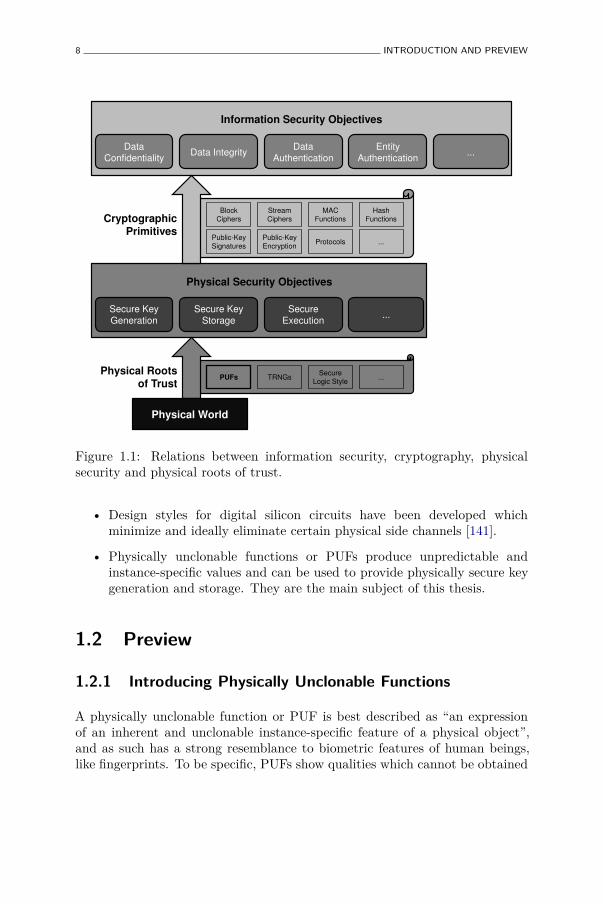
In order to provide these physical security objectives, we cannot rely onmathematical reductions anymore. Instead, we need to develop physicaltechniques and primitives which, based on physical reasoning, can be trustedto withstand certain physical attacks and can hence provide certain physicalsecurity objectives. We call such primitives physical roots of trust. Figure 1.1shows how information security objectives can be achieved from physicalsecurity and eventually from physical roots of trust, i.e. trusted primitiveswhich are rooted in the actual physical world. Possible candidates of physicalroots of trust are:
• True random number generators or TRNGs [42, 126] harvest randomnumbers from truly physical sources of randomness and can therefore betrusted to produce highly random keys for cryptographic purposes.
8 INTRODUCTION AND PREVIEW
Information Security Objectives
Physical Security Objectives
Data
Confidentiality Data Integrity
Data
Authentication
Entity
Authentication ...
Secure Key
Generation
Secure Key
Storage
Secure
Execution ...
Block
Ciphers
Stream
Ciphers
MAC
Functions
Hash
Functions
Public-Key
Signatures
Public-Key
Encryption Protocols ...
Cryptographic Primitives
PUFs TRNGs Secure
Logic Style ...
Physical Roots of Trust
Physical World
Figure 1.1: Relations between information security, cryptography, physicalsecurity and physical roots of trust.
• Design styles for digital silicon circuits have been developed whichminimize and ideally eliminate certain physical side channels [141].
• Physically unclonable functions or PUFs produce unpredictable andinstance-specific values and can be used to provide physically secure keygeneration and storage. They are the main subject of this thesis.
1.2 Preview
1.2.1 Introducing Physically Unclonable Functions
A physically unclonable function or PUF is best described as “an expressionof an inherent and unclonable instance-specific feature of a physical object”,and as such has a strong resemblance to biometric features of human beings,like fingerprints. To be specific, PUFs show qualities which cannot be obtained
PREVIEW 9
from cryptographic reductions, but require a physical basis to establish them,the most noteworthy being physical unclonability. This means that throughphysical reasoning it is shown that producing a physical clone of a PUF isextremely hard or impossible.
PUF Constructions. The physical motivation for claiming unclonability ofan inherent instance-specific feature is found in the technical limitations of theproduction of physical objects. Even with extreme control over a manufacturingprocess, no two physically exactly identical objects can be created due to theinfluence of random and uncontrollable effects. Typically, these influencesare very small and only take effect at (sub-)microscopic scales, but leavethere random marks nonetheless. A high-precision measurement of thesemarks serves as an inherent and instance-specific feature. Moreover, creatinga second object which produces a similar measurement is infeasible from aphysical perspective, and often even technically impossible. Generating sucha measurement with an accuracy high enough to distinguish these instance-specific features is the primary goal in the study of PUF constructions. Thebasic technique which is typically used, is to design a construction, eitherexternal or internal to the object, which amplifies these microscopic differencesto practically observable levels.
PUF Properties. A wide variety of PUF constructions based on this principleare possible and have been proposed, considering objects from many differentmaterials and technologies, each with their own specific intricacies and usefulproperties. In order to apply PUFs to reach physical security objectives,a generic and objective description of these PUF properties is required.Moreover, it is important to distinguish truly PUF-specific properties fromother useful qualities which are inherent to a specific constructions but cannotbe generalized to all PUFs.
PUF Applications. Based on their unclonability and other useful properties,PUFs can fulfill a number of physical security objectives when applied in theright way. Besides taking advantage of the physical security properties of PUFs,such PUF-based applications also need to deal with the practical limitationsof the construction. This is accomplished by deploying a PUF in a schemetogether with other primitives that enhance its qualities. Deploying a PUF ina larger system typically leads to trade-offs, and hence optimization problems,between the aspired security level and the implementation restrictions of theapplication. Based on an analysis of such a scheme, some PUF constructionswill offer better trade-offs than other ones.
10 INTRODUCTION AND PREVIEW
1.2.2 Thesis Outline and Contributions
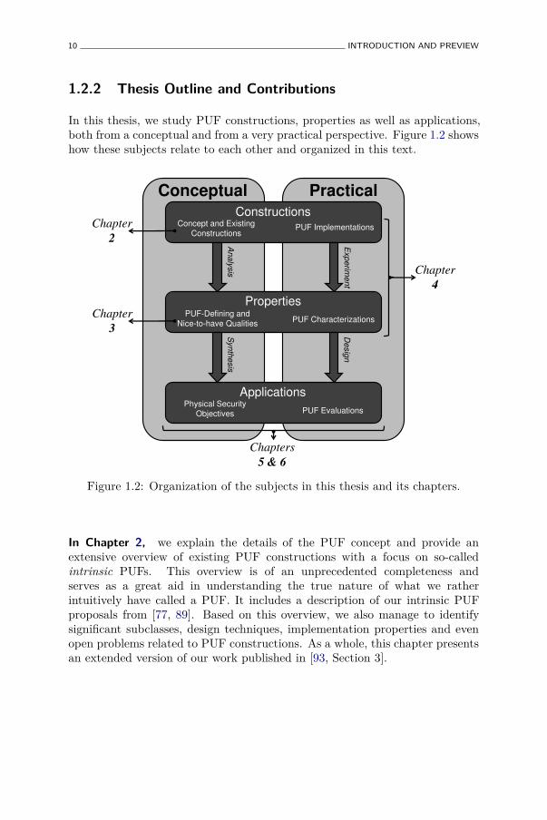
In this thesis, we study PUF constructions, properties as well as applications,both from a conceptual and from a very practical perspective. Figure 1.2 showshow these subjects relate to each other and organized in this text.
Constructions
Properties
Applications
Concept and Existing
Constructions PUF Implementations
PUF-Defining and
Nice-to-have Qualities
Physical Security
Objectives
PUF Characterizations
PUF Evaluations
Chapter
2
Chapter
3
Chapter
4
Chapters
5 & 6
Analy
sis
Experim
ent
Desig
n
Conceptual Practical
Synth
esis
Figure 1.2: Organization of the subjects in this thesis and its chapters.
In Chapter 2, we explain the details of the PUF concept and provide anextensive overview of existing PUF constructions with a focus on so-calledintrinsic PUFs. This overview is of an unprecedented completeness andserves as a great aid in understanding the true nature of what we ratherintuitively have called a PUF. It includes a description of our intrinsic PUFproposals from [77, 89]. Based on this overview, we also manage to identifysignificant subclasses, design techniques, implementation properties and evenopen problems related to PUF constructions. As a whole, this chapter presentsan extended version of our work published in [93, Section 3].
PREVIEW 11
In Chapter 3, we identify and define different meaningful properties at-tributed to PUFs and, based on Chapter 2, we analyse if and to what extentactual PUF constructions attain them. From this analysis, a number of theseproperties are found to be defining for the concept of a PUF, while others aremere convenient qualities but are in no way guaranteed for all PUFs. This isa more detailed version of our analysis published in [93, Section 4] In order toincrease their potential in theoretical constructions, a highly formal frameworkfor using PUFs and their most important properties is also introduced. Wepublished the initial description of this framework in [8].
In Chapter 4, we implement a significant subset of studied intrinsic PUFconstructions on a realistic silicon platform (65 nm CMOS ASIC) andexperimentally verify their behavior at nominal condition and at extremetemperature and voltage corners. We capture the qualities of each studiedconstruction in a small number of meaningful statistics. Additionally, weanalyse the unpredictability of each PUF by introducing heuristic upper boundson their entropy density. A preliminary version of our analysis and a descriptionof the test chip design is published in [88].
In Chapter 5, we investigate how PUFs can be used to identify distinctobjects, and ultimately provide entity authentication. Quality metrics forassessing identification performance are discussed and applied on the PUFconstructions studied in Chapter 4, yielding a classification of their identifyingcapabilities. We introduce a PUF-based authentication protocol innovativelycombining a PUF and other primitives. This is an extended version of theprotocol we proposed in [150]. Authentication performance metrics similar tothose for identification are assessed for the constructions from Chapter 4.
In Chapter 6, it is explained how PUFs can be used to obtain secure keygeneration and storage. Existing notions and techniques for key generation arediscussed, and a practical new variant is proposed which yields a significant gainin efficiency. Based on the design constraints of a convenient construction of apractical PUF-based key generator, the PUF implementations from Chapter 4are assessed for their key generation capacities. To conclude, we present a front-to-back PUF-based key generator design and a fully functional FPGA referenceimplementation thereof. The results discussed in this chapter are based on ourpublished works in [90–92].
In Chapter 7, we summarize the most important findings of this thesis andpropose a number of interesting future research directions.


Chapter 2
Physically UnclonableFunctions: Concept andConstructions
He says there’s no doubt about itIt was the myth of fingerprintsI’ve seen them all and manThey’re all the same
All Around the World or the Myth of FingerprintsPaul Simon
2.1 Introduction
2.1.1 The PUF Concept
Being the main subject of this thesis, it is important to clarify and definethe basic concept of a physically unclonable function or PUF. However, for avariety of reasons, this task turns out to be less straightforward than expected.The collection of proposed constructions labelled ‘PUF’ is growing at such apace, both in depth and breadth, that one can easily call it a zoo at this
13
14 PHYSICALLY UNCLONABLE FUNCTIONS: CONCEPT AND CONSTRUCTIONS
moment.1 There is also an equally substantial group of constructions whichcould, but are for the moment not, called a ‘PUF’, among other reasons becausethey were proposed before the acronym ‘PUF’ had been coined, or becausethey were proposed by authors unfamiliar with the acronym, e.g. in fieldsoutside hardware security engineering. All these differing constructions aremoreover proposed in a greatly varying patchwork of implementation materials,technologies and platforms. Finding similar or even identifying propertieswhich accurately capture what is understood to be a PUF is hence far fromtrivial. In this chapter and the next, we discuss the PUF concept in greatdetail in order to do exactly that. First, by extensively studying existingPUF constructions in Chapter 2, and next by describing, assessing and finallyformalizing the observed properties of PUFs in Chapter 3.
On PUFs and Fingerprints
In an attempt to express the concept of a PUF in a single phrase, one of thebest possible descriptions would be: “a PUF is an object’s fingerprint”. PUFsare similar to fingerprints for more than one reason:
• A human fingerprint is a feature which strongly expresses individualism,i.e. it answers the question “Which human is this?”. This as opposedto other features like, e.g. having two eyes and ears and walking on twolegs, which express essentialism, i.e. answering the question “What is ahuman?”. In a more inanimate sense, a PUF bears the same meaning fora class of objects: a PUF is an identifying feature of a specific instanceof a class of objects, or for short an instance-specific feature.
• As an individualising feature, a fingerprint is also inherent, i.e. everyhuman being is born with fingerprints, unlike other identifying qualitieslike a name or a written signature, which are bestowed upon or acquiredby an individual after birth. In the same way, PUFs are inherently presentin an object from its creation, as a result of unique variations during itscreation process.
• Finally, as an inherent individualising feature, fingerprints are alsounclonable, i.e. the physical and biological processes which determinea human being’s fingerprint are beyond any level of meaningful controlwhich would allow to create a second individual with the same inherentfingerprints.2 This even holds for human beings sharing the same genetic
1By analogy with the Complexity Zoo [4] and the SHA-3 Zoo [5].2By unclonable we do not mean that it is impossible to create or obtain a facsimile of a
person’s fingerprint; in fact human beings create copies of their fingerprints every time theytouch a smooth surface.
INTRODUCTION 15
material, like identical twins. Hence even a (hypothetical) biologicalclone of a person would not share that person’s fingerprints. Also in thisaspect are PUFs very similar to fingerprints. In fact, by being the centralspecifier in the term ‘physically unclonable functions’, it is expressed that(physical) unclonability is one of the core properties of a PUF.
Following this discussion, we propose the following colloquial dictionarydefinition of the PUF concept: “a PUF is an expression of an inherentand unclonable instance-specific feature of a physical object”. By indicatingthat a PUF is always object-related, we explicitly distinguish PUFs fromfingerprints and other biometric parameters which naturally reflect on humanbeings. However, as discussed above, in many aspects PUFs and biometrics areequivalent.
2.1.2 Chapter Goals
Order in the PUF Zoo
The amount of published results on physically unclonable functions hasincreased exponentially over the last years, and the need for a synthesizingeffort presents itself. This chapter, which is an updated and extended versionof our work in [93], is the first to make an objective, large-scale and in-depthoverview of the myriad of PUFs which have been proposed over the years. Themain goals of this overview are:
• Present an as-complete-as-possible reference list of PUF and PUF-likeproposals to date, with a focus on so-called intrinsic PUFs.
• Introduce and apply a classification of PUF constructions based onpractical considerations.
• Present a common descriptive framework for assessing the basic function-ality and quality of a PUF, and use it to produce an as fair as possiblecomparative quantitative analysis of different PUF implementationsbased on published experimental results.
Besides these clear objectives, this overview will also be of great aid inidentifying interesting subclasses, properties, applications, and even openproblems in the field of PUFs.
16 PHYSICALLY UNCLONABLE FUNCTIONS: CONCEPT AND CONSTRUCTIONS
2.1.3 Chapter Overview
Before we start describing different PUF constructions and their qualities, wewill in Section 2.2 introduce the basic nomenclature and notational conventionsrelated to PUFs which we will use throughout this thesis. These conventionsmake it much easier to relate and compare identical concepts in often widelydiffering implementations and data sets, and it is therefore highly recommendedto read this section first. In Section 2.3, we delve deeper into the semanticsof the acronym ‘PUF’ and also discuss a number of possible classificationsin the large variety of PUF constructions which have been proposed overtime. The main body of this chapter is a very extensive overview of knownPUF constructions,3 detailing the implementation details of each proposaland reporting experimental results, if any. In this thesis, we mainly focuson intrinsic PUF constructions which are discussed in Section 2.4. Formore information on existing non-intrinsic PUF constructions we refer toAppendix B. In Section 2.5, a number of concepts are discussed which presentextensions or modes of operation of PUFs. Finally, we conclude this chapter inSection 2.6.
2.2 Preliminaries
2.2.1 Conventions on Describing PUFs
Formally describing the operation of a PUF is a tedious yet important task.Due to the multitude of different PUF constructions and different ways ofconsidering a PUF outcome, one quickly runs the risk of either introducingconfusion due to an ambiguous description or loosing important details dueto a too sparse description. Here, we introduce the verbal and notationaldescription of PUFs which we will use and build upon throughout the restof this thesis. Since this is only intended as a convenient but clear notationformat, we refrain at this point as much as possible from making assumptionsor putting restrictions on the underlying notions. Instead, we limit theseconventions to the most basic concepts required to formally talk about PUFs.For completeness, the basic mathematical notations and definitions used in thissection and the rest of this thesis are shortly introduced in Appendix A.
3We aim at giving an exhaustive overview of PUF proposals up to date, but with theplethora of new constructions appearing in the latest years, it is very likely that some aremissing.
PRELIMINARIES 17
PUF Class
We first introduce the notion of a PUF class, denoted as P, which is thecomplete description of a particular PUF construction type. A PUF classprovides a creation procedure P.Create which is invoked to create instances ofP. In general P.Create is a probabilistic procedure, which we make explicitwhen necessary by providing it with a randomized input P.Create(rC), withrC $← {0, 1}∗ representing an undetermined number of fair coin tosses.
From a practical point of view, P represents the detailed structural design orblueprint of a PUF construction and P.Create the detailed (physical) productionprocess to build the design.
PUF Instance
A PUF instance puf is a discrete instantiation of a PUF class P, as generated byits creation procedure P.Create. In all respects, a PUF class can be consideredto be the set of all its created instances:
P ≡ {pufi ← P.Create(rC
i ) : ∀i, rC
i
$← {0, 1}∗} .
A PUF instance puf is considered as a particular crystallized state of theconstruction described by its PUF class P. The construction of many PUFclasses allows that part of a PUF instance’s state is configurable, i.e. it is notfixed by the creation procedure but can be set and easily modified by meansof an external input. When required, we specify the configurable state x of aPUF instance puf as puf(x).
From a practical point of view, the state represented by a PUF instancepuf is the exact (physical) structure of a produced PUF construction. Theconfigurable part of a PUF instance’s state is generally called the challengewhich is applied to the PUF instance, and we will use the same terminologyin this thesis. The set of all possible challenges x which can be applied to aninstance of a PUF class P is denoted as XP .
PUF Evaluation
Every PUF instance puf provides an evaluation procedure puf.Eval whichproduces a quantitative outcome representing a measurement of the PUFinstance. The outcome produced by puf.Eval depends on the state representedby the PUF instance. When the PUF instance is challengeable, we write:
18 PHYSICALLY UNCLONABLE FUNCTIONS: CONCEPT AND CONSTRUCTIONS
puf(x).Eval. In general puf(x).Eval is also a probabilistic procedure which weagain make explicit when necessary as puf(x).Eval(rE $
← {0, 1}∗).
From a practical point of view, a PUF instance evaluation is the outcomeof a (physical) experiment, generating a particular measurement of the PUFinstance’s physical state at that moment. Such a measurement is generallycalled the response of the PUF instance and we will use the same terminology.The class of all possible response values which a PUF instance of a PUF classP can produce, is denoted as YP .
For many PUF classes, the outcome of a PUF instance evaluation is alsoaffected by external physical parameters, e.g. environment temperature, supplyvoltage level, etc. We call this the condition of the evaluation. When required,we denote this as puf(x).Evalα, e.g. with α = (Tenv = 80 °C) meaning thatthis evaluation took place at an environment temperature of 80 °C. Whenthe condition specifier α is omitted, one may assume an evaluation at nominaloperating conditions.
Short-hand Notation
To avoid the rather verbose use of the randomization variables rC and rE, weintroduce a more convenient and compact notation using random variables.
Creation of a random PUF instance:
pufi ← P.Create(rC
i
$← {0, 1}∗) , becomes
PUF← P.Create , or even shorter PUF← P .
Random evaluation of PUF instance pufi on challenge x:
y(j)i (x)← pufi(x).Eval(rE
j
$← {0, 1}∗) , becomes
Yi(x)← pufi(x).Eval , or even shorter Yi(x)← pufi(x) .
Random evaluation of a random PUF instance on challenge x:
Y (x)← PUF(x).Eval , or shorter Y (x)← PUF(x) .
PRELIMINARIES 19
2.2.2 Details of a PUF Experiment
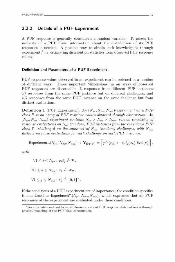
A PUF response is generally considered a random variable. To assess theusability of a PUF class, information about the distribution of its PUFresponses is needed. A possible way to obtain such knowledge is throughexperiment,4 i.e. estimating distribution statistics from observed PUF responsevalues.
Definition and Parameters of a PUF Experiment
PUF response values observed in an experiment can be ordened in a numberof different ways. Three important ‘dimensions’ in an array of observedPUF responses are discernable: i) responses from different PUF instances;ii) responses from the same PUF instance but on different challenges; andiii) responses from the same PUF instance on the same challenge but fromdistinct evaluations.
Definition 1 (PUF Experiment). An (Npuf , Nchal, Nmeas)-experiment on a PUFclass P is an array of PUF response values obtained through observation. An(Npuf , Nchal, Nmeas)-experiment contains Npuf × Nchal × Nmeas values, consisting ofresponse evaluations on Npuf (random) PUF instances from the considered PUFclass P, challenged on the same set of Nchal (random) challenges, with Nmeas
distinct response evaluations for each challenge on each PUF instance.
ExperimentP(Npuf , Nchal, Nmeas)→ YExp(P) =[y
(j)i (xk)← pufi(xk).Eval(rE
j)]
,
with
∀1 ≤ i ≤ Npuf : pufi$← P ,
∀1 ≤ k ≤ Nchal : xk$← XP ,
∀1 ≤ j ≤ Nmeas : rE
j
$← {0, 1}∗ .
If the conditions of a PUF experiment are of importance, the condition specifieris mentioned as Experimentα
P(Npuf , Nchal, Nmeas), which expresses that all PUFresponses of the experiment are evaluated under these conditions.
4An alternative method to learn information about PUF response distributions is throughphysical modeling of the PUF class construction.
20 PHYSICALLY UNCLONABLE FUNCTIONS: CONCEPT AND CONSTRUCTIONS
2.2.3 PUF Response Intra-Distance
Intra-Distance Definition
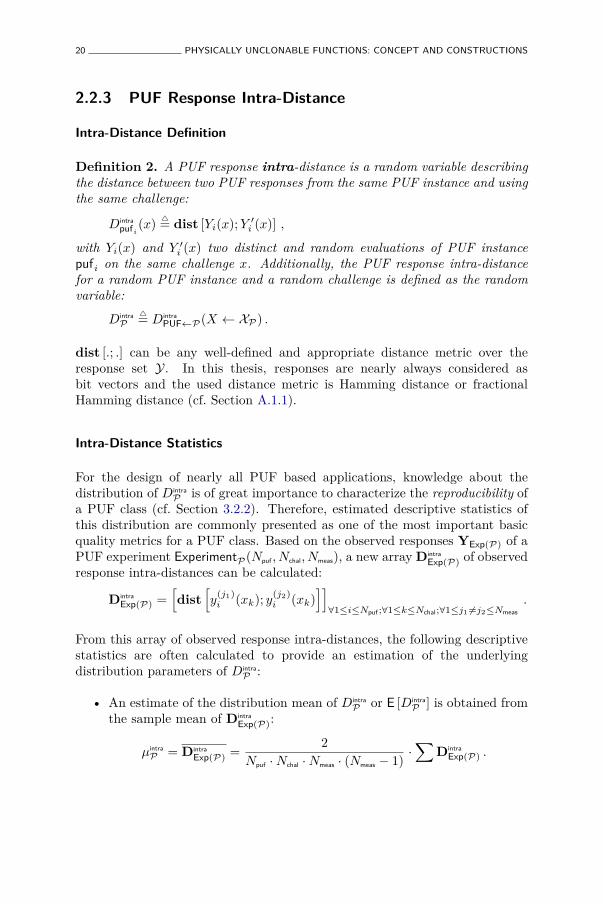
Definition 2. A PUF response intra-distance is a random variable describingthe distance between two PUF responses from the same PUF instance and usingthe same challenge:
Dintra
pufi
(x)△
= dist [Yi(x); Y ′i (x)] ,
with Yi(x) and Y ′i (x) two distinct and random evaluations of PUF instancepufi on the same challenge x. Additionally, the PUF response intra-distancefor a random PUF instance and a random challenge is defined as the randomvariable:
Dintra
P△
= Dintra
PUF←P(X ← XP) .
dist [.; .] can be any well-defined and appropriate distance metric over theresponse set Y. In this thesis, responses are nearly always considered asbit vectors and the used distance metric is Hamming distance or fractionalHamming distance (cf. Section A.1.1).
Intra-Distance Statistics
For the design of nearly all PUF based applications, knowledge about thedistribution of Dintra
P is of great importance to characterize the reproducibility ofa PUF class (cf. Section 3.2.2). Therefore, estimated descriptive statistics ofthis distribution are commonly presented as one of the most important basicquality metrics for a PUF class. Based on the observed responses YExp(P) of aPUF experiment ExperimentP(Npuf , Nchal, Nmeas), a new array Dintra
Exp(P) of observedresponse intra-distances can be calculated:
Dintra
Exp(P) =[dist
[y
(j1)i (xk); y
(j2)i (xk)
]]
∀1≤i≤Npuf ;∀1≤k≤Nchal;∀1≤j1 6=j2≤Nmeas
.
From this array of observed response intra-distances, the following descriptivestatistics are often calculated to provide an estimation of the underlyingdistribution parameters of Dintra
P :
• An estimate of the distribution mean of Dintra
P or E [Dintra
P ] is obtained fromthe sample mean of Dintra
Exp(P):
µintra
P = Dintra
Exp(P) =2
Npuf ·Nchal ·Nmeas · (Nmeas − 1)·∑
Dintra
Exp(P) .
PRELIMINARIES 21
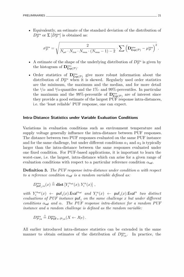
• Equivalently, an estimate of the standard deviation of the distribution ofDintra
P or Σ [Dintra
P ] is obtained as:
σintra
P =
√2
Npuf ·Nchal ·Nmeas · (Nmeas − 1)− 2·∑(
Dintra
Exp(P) − µintra
P
)2
.
• A estimate of the shape of the underlying distribution of Dintra
P is given bythe histogram of Dintra
Exp(P).
• Order statistics of Dintra
Exp(P) give more robust information about thedistribution of Dintra
P when it is skewed. Regularly used order statisticsare the minimum, the maximum and the median, and for more detailthe 1/4- and 3/4-quantiles and the 1%- and 99%-percentiles. In particularthe maximum and the 99%-percentile of Dintra
Exp(P) are of interest sincethey provide a good estimate of the largest PUF response intra-distances,i.e. the ‘least reliable’ PUF response, one can expect.
Intra-Distance Statistics under Variable Evaluation Conditions
Variations in evaluation conditions such as environment temperature andsupply voltage generally influence the intra-distance between PUF responses.The distance between two PUF responses evaluated on the same PUF instanceand for the same challenge, but under different conditions α1 and α2 is typicallylarger than the intra-distance between the same responses evaluated underone fixed condition. For PUF-based applications, it is important to learn theworst-case, i.e. the largest, intra-distance which can arise for a given range ofevaluation conditions with respect to a particular reference condition αref .
Definition 3. The PUF response intra-distance under condition α with respectto a reference condition αref is a random variable defined as:
Dintra
pufi;α(x)
△
= dist [Y αrefi (x); Y α
i (x)] ,
with Y αrefi (x) ← pufi(x).Evalαref and Y α
i (x) ← pufi(x).Evalα two distinctevaluations of PUF instance pufi on the same challenge x but under differentconditions αref and α. The PUF response intra-distance for a random PUFinstance and a random challenge is defined as the random variable:
Dintra
P;α△
= Dintra
PUF←P;α(X ← XP) .
All earlier introduced intra-distance statistics can be extended in the samemanner to obtain estimates of the distribution of Dintra
P;α. In practice, the
22 PHYSICALLY UNCLONABLE FUNCTIONS: CONCEPT AND CONSTRUCTIONS
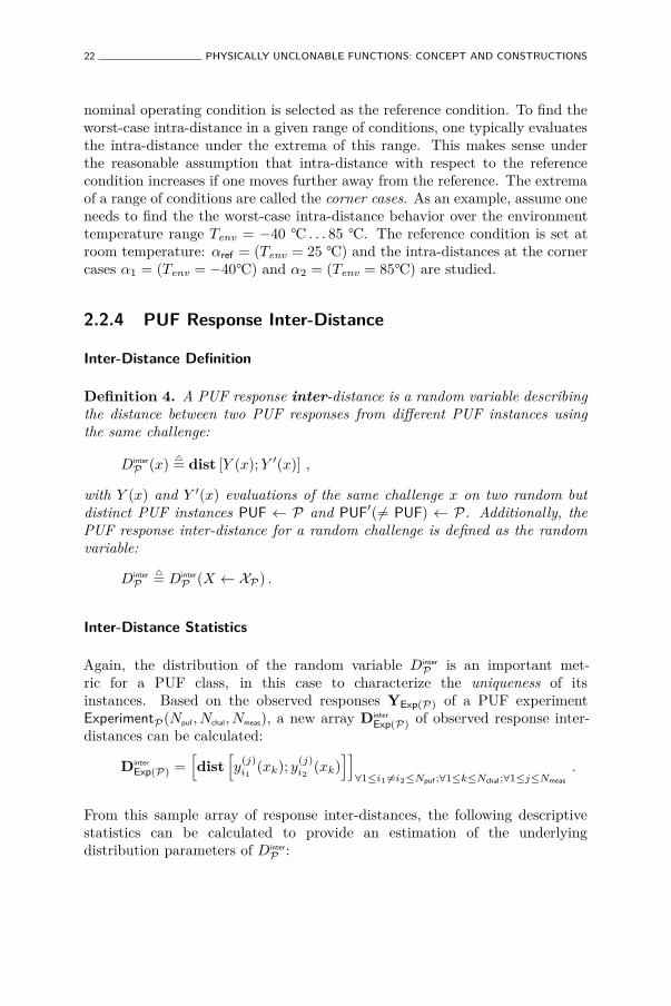
nominal operating condition is selected as the reference condition. To find theworst-case intra-distance in a given range of conditions, one typically evaluatesthe intra-distance under the extrema of this range. This makes sense underthe reasonable assumption that intra-distance with respect to the referencecondition increases if one moves further away from the reference. The extremaof a range of conditions are called the corner cases. As an example, assume oneneeds to find the the worst-case intra-distance behavior over the environmenttemperature range Tenv = −40 °C . . . 85 °C. The reference condition is set atroom temperature: αref = (Tenv = 25 °C) and the intra-distances at the cornercases α1 = (Tenv = −40°C) and α2 = (Tenv = 85°C) are studied.
2.2.4 PUF Response Inter-Distance
Inter-Distance Definition
Definition 4. A PUF response inter-distance is a random variable describingthe distance between two PUF responses from different PUF instances usingthe same challenge:
Dinter
P (x)△
= dist [Y (x); Y ′(x)] ,
with Y (x) and Y ′(x) evaluations of the same challenge x on two random butdistinct PUF instances PUF ← P and PUF′(6= PUF) ← P. Additionally, thePUF response inter-distance for a random challenge is defined as the randomvariable:
Dinter
P△
= Dinter
P (X ← XP) .
Inter-Distance Statistics
Again, the distribution of the random variable Dinter
P is an important met-ric for a PUF class, in this case to characterize the uniqueness of itsinstances. Based on the observed responses YExp(P) of a PUF experimentExperimentP(Npuf , Nchal, Nmeas), a new array Dinter
Exp(P) of observed response inter-distances can be calculated:
Dinter
Exp(P) =[dist
[y
(j)i1
(xk); y(j)i2
(xk)]]
∀1≤i1 6=i2≤Npuf ;∀1≤k≤Nchal;∀1≤j≤Nmeas
.
From this sample array of response inter-distances, the following descriptivestatistics can be calculated to provide an estimation of the underlyingdistribution parameters of Dinter
P :
TERMINOLOGY AND CLASSIFICATION 23
• The sample mean of Dinter
Exp(P) as an estimate of E [Dinter
P ]:
µinter
P = Dinter
Exp(P) =2
Npuf · (Npuf − 1) ·Nchal ·Nmeas
·∑
Dinter
Exp(P) .
• Equivalently, an estimate of Σ [Dinter
P ] is obtained as:
σinter
P =
√2
Npuf · (Npuf − 1) ·Nchal ·Nmeas − 2·∑(
Dinter
Exp(P) − µinter
P
)2
.
• A estimate of the shape of the underlying distribution of Dinter
P is given bythe histogram of Dinter
Exp(P).
• The order statistics of Dinter
Exp(P) again give more robust information aboutthe distribution of Dinter
P when it is skewed. For PUF response inter-distances, in particular the minimum and the 1%-percentile of Dinter
Exp(P) areof interest since they are a good estimate of the smallest inter-distance,i.e. the ‘least unique’ PUF instance pair, one can expect.
Inter-Distance Statistics under Variable Evaluation Conditions
The inter-distance between PUF responses is also susceptible to variations onevaluation conditions. However, for typical PUF based applications, the initialgeneration or enrollment is done in a secure environment under controlledconditions, and only the inter-distance of evaluations under the referencecondition αref is of importance. Therefore, no extension of the definition ofinter-distance to varying conditions is required in that case. In applicationswhere the initial enrollment is done in the field, the susceptibility of the inter-distance to the evalution conditions does need to be taken into account. In thisthesis, we only consider enrollment at reference conditions.
2.3 Terminology and Classification
In Section 2.3.1, we elaborate on the origin and the meaning of the acronym‘PUF’. As will become clear from this chapter, the growing popularity of PUFshas caused a proliferation of different constructions and concepts all labelledas PUFs. In an attempt to bring some order into this zoo, a number ofclassification attempts were made:
24 PHYSICALLY UNCLONABLE FUNCTIONS: CONCEPT AND CONSTRUCTIONS
• Based on the implementation technology of the proposed construction:non-electronic PUF versus electronic PUFs versus silicon PUFs, asdiscussed in Section 2.3.2
• Based on a more general set of physical construction properties: non-intrinsic versus intrinsic PUFs, as discussed in Section 2.3.3
• Based on the algorithmic properties of their challenge-response behavior:weak versus strong PUFs, as discussed in Section 2.3.4
2.3.1 “PUFs: Physical(ly) Unclon(e)able Functions”
To PUF or not to PUF?
In addition to proposing a new optics-based PUF construction, Pappu [109] in2001 was the first to also describe and define the more general concept of a PUF,which he introduced at the time as a physical one-way function. Shortly after,Gassend et al. [47] proposed a new silicon-based PUF construction and definedit similarly as a physical random function, but they opted for the acronym PUF,standing for physical unclonable function, to avoid confusion with the conceptof a pseudo-random function which in cryptography is already abbreviated asPRF.
In the mean time, the acronym ‘PUF’ has become a catch-all for a varietyof often very different constructions and concepts, but which share a numberof interesting properties. Some of these constructions were proposed beforethe term PUF was coined, and were hence not called PUFs from the beginning.Other constructions were proposed in fields other than cryptographic hardware,where the term PUF is yet unknown. Depending on which properties areassumed to be defining for PUFs (and depending on whom you ask), suchconstructions are still called PUFs.
Having been used as a label for many different constructions, the literalsemantic meaning of the acronym PUF as “physical unclonable function”has been partially lost, up to the point where some consider it a misnomer.Moreover, slight variations on the actual wording were introduced over time,as expressed in the title of this section. In this thesis, the acronym PUF doesgenerally not refer to its literal meaning. Instead, it is used as the collectivenoun for the variety of proposed constructions sharing a number of interestingproperties. One of the main goals of the next chapter is to list known PUFconstructions and identify such a least common subset of defining properties.
TERMINOLOGY AND CLASSIFICATION 25
Physical versus Physically?
Originally, the acronym PUF stands for physical unclonable function, but laterthe variant physically unclonable function also got into use. Both terms arestill used today and refer to the same concept. The choice for one or theother depends mainly on the preference of the author. However, from a strictsemantic point of view, there is a small difference in meaning. A physicalunclonable function is ‘a physical function which is unclonable’ whereas aphysically unclonable function is ‘a function which is physically unclonable’.In Section 3.2.10, we argue why we consider the second interpretation to be amore fitting description of the actual concept of a PUF.
Unclon(e)able?
The adjective unclonable is the central specifier in the acronym, reflecting thedistinguishing property of a PUF. However, the actual meaning of unclonableis not clearly defined. In a broader sense, one first needs to define what oneconsiders a clone. Especially in the context of PUFs, this has lead to somedebate. In many scenarios, one solely observes the input-output (or challenge-response) behavior of a PUF and only rarely the actual physical entity. Inthat respect, any construction which accurately mimics the behavior of aparticular PUF could be considered a clone thereof. On the other hand, ifone takes the physical aspect into account, cloning gets a different meaning,e.g. one could require a clone to have the same behavior and the same physicalappearance as the original, or even more strictly, one could require a clone to bemanufactured in the same production process as the original. The distinctionbetween the former and latter interpretation of a clone is often made specificas a mathematical versus a physical clone.
Whether or not to write the silent ‘e’ in unclon(e)able is somewhat arbitrary.Generally, the terminal silent -e is dropped when appending the suffix -ableto a verb [1], e.g. movable, blamable, unless the verb ends in -ce or -ge whichis not the case here. However, in scientific literature on computing the form(un)cloneable is more common, likely due to the existence of an homonymousbut unrelated interface in the popular Java™ programming language [2].An internet search gives roughly a five-to-one preference of unclonable overuncloneable, although peculiarly for clonable versus cloneable these odds arereversed. In this thesis, the form unclonable is preferred.
26 PHYSICALLY UNCLONABLE FUNCTIONS: CONCEPT AND CONSTRUCTIONS
Function?
In the pure mathematical sense, a PUF is not even strictly a function, since asingle input (challenge) can be related to more than a single output (response)due to the uncontrollable effects of physical environment and random noise onthe response generation. Therefore, a more fitting mathematical descriptionof a PUF is as a probabilistic function, i.e. a function for which part of theinput is an uncontrollable random variable. This is sometimes made explicit byproviding an additional input r to a function, representing an (undetermined)number of fair coin tosses: r
$← {0, 1}∗. Alternatively, one can consider the
outcome of a probabilistic function to be a random variable with a particularprobability distribution, instead of a deterministic value.
2.3.2 Non-electronic, Electronic and Silicon PUFs
PUFs and PUF-like constructions have been proposed based on a widevariety of technologies and materials such as glass, plastic, paper, electroniccomponents and silicon integrated circuits (ICs). A possible classification ofPUF constructions is based on the electronic nature of their identifying features.
Non-electronic PUFs
A first relatively large class contains PUF proposals with an inherentlynon-electronic nature. Their PUF-like behavior is based on non-electronictechnologies or materials, e.g. the random fiberstructure of a sheet of paperor the random reflection of scattering characteristics of an optical medium(cf. Section B.1). Note that the denominator non-electronic reflects the originof the PUF behavior, and not the way PUF responses are processed or stored,which often does use electronics and digital circuitry.
Electronic PUFs
On the other side of the spectrum are electronic PUFs, i.e. constructionscontaining random variations in their electronic characteristics, e.g. resistance,capacitance, etc. These variations are generally also measured in an electronicway. Note that there is not always a sharp distinction between electronicand non-electronic PUFs, e.g. a construction called RF-DNA [35] consists ofrandomly arranged copper wires fixated in a flexible silicone medium whichcould be considered non-electronic, whereas LC-PUFs [51] are in fact passive
TERMINOLOGY AND CLASSIFICATION 27
LC resonance circuits which could be considered electronic in nature. However,the manner in which they generate responses is practically the same, i.e. therandom influence they have on an imposed wireless radio-frequency field(cf. Section B.2). Another side note is that variation in electronic behavioris practically always a consequence of variations in non-electronic parametersat a lower level of physical abstraction, e.g. the length and section of a metalwire determine its resistance, the area and distances between two conductorsdetermine their capacitance, etc.
Silicon PUFs
A major subclass of electronic PUFs are so-called silicon PUFs, i.e. integratedelectronic circuits exhibiting PUF behavior which are embedded on a siliconchip. The term silicon PUF and the first practical realization of a PUFstructure in silicon were introduced by Gassend et al. [47]. Since siliconPUFs can be directly connected to standard digital circuitry embedded on thesame chip, they can be immediately deployed as a hardware building block incryptographic implementations. For this reason, it is evident that silicon PUFsare of particular interest for security solutions and they are the main type ofPUF construction we focus on in this thesis.
2.3.3 Intrinsic and Non-intrinsic PUFs
An important classification of PUFs based on their construction properties isthat of intrinsic PUFs as initially proposed by Guajardo et al. [50]. In a slightlyadapted form, we consider that a PUF construction needs to meet at leasttwo conditions to be called an intrinsic PUF: i) its evaluations are performedinternally by embedded measurement equipment, and ii) its random instance-specific features are implicitly introduced during its production process. Next,we discuss both properties in more detail and highlight the specific practicaland security advantages of intrinsic PUFs.
External versus Internal Evaluations
A PUF evaluation is a physical measurement which can take many forms. Wedistinguish between external and internal evaluations. An external evaluationis a measurement of features which are externally observable and/or which iscarried out using equipment which is external to the physical entity containingthe features. On the other side are internal evaluations, i.e. measurements ofinternal features which are carried out by equipment completely embedded on
28 PHYSICALLY UNCLONABLE FUNCTIONS: CONCEPT AND CONSTRUCTIONS
the instance itself. This might seem a rather arbitrary distinction, but thereare some important advantages to internal evaluations:
• The first is a purely practical advantage. Having the measurementequipment embedded on every PUF instance means that every PUF in-stance can evaluate itself without any external limitations or restrictions.Internal evaluations are typically also more accurate since there is lessopportunity for outside influences and measurement errors.
• Secondly, there is a rather important security advantage to internalevaluations, since the PUF responses originate inside the embeddingobject. This means that, as long as an instance does not disclose aresponse to the outside world, it can be considered an internal secret.This is of particular interest when the embedding object is a digital IC,since in that case the PUF response can be used immediately as a secretinput for an embedded implementation of a cryptographic algorithm.
A possible disadvantage of an internal evaluation is that one needs to trustthe embedded measurement equipment, since it is impossible to externallyverify whether the measurement takes place as expected. This as opposedto an external evaluation for which it is often possible to actually observe themeasurement in progress.
Explicit versus Implicit Random Variations
A second construction-based distinction considers the source of the randomnessof the evaluated features in a PUF. The manufacturing process of the PUFinstances can contain an explicit randomization procedure with the sole purposeof introducing random features which will later be measured when the PUF isevaluated. Alternatively, the measured random features can also be an implicitside effect of the standard production flow of the embedding object, i.e. theyarise naturally as an artifact of uncontrollable effects during the manufacturingprocess. Again, there are some subtle but interesting advantages to PUFconstructions based on implicit random variations:
• From a practical viewpoint, implicit random variations generally comeat no extra cost since they are already (unavoidably) present in theproduction process. Introducing an explicit randomization procedure onthe other hand can be costly, particularly due to timing constraints inthe manufacturing flow of high-volume products.
• Implicit random variability in manufacturing or so-called process varia-tions which occur during a production process are generally undesirable
TERMINOLOGY AND CLASSIFICATION 29
since they have a negative impact on yield. This means that manufac-turers already take elaborate measures to reduce process variations asmuch as possible. However, as it turns out, completely avoiding anyrandom effect during manufacturing is technically impossible and processvariations are always present. As a consequence, PUF constructions basedon implicit process variations have the interesting security advantagethat even the manufacturer, having full details and control over theirproduction process, cannot remove or control the random features at thecore of the PUF’s functionality.
Non-Intrinsic PUF Constructions
A variety of PUF constructions have been proposed which we label non-intrinsic according to this classification, e.g. :
• The optical PUF as proposed by Pappu et al. [110] [109], which is basedon the unique speckle pattern which arises when shining a laser on atransparent material with randomly solved scattering particles.
• The coating PUF as proposed by Tuyls et al. [145], which is based on theunique capacitance between two metal lines in a silicon chip whose toplayer consists of a coating with randomly distributed dielectric particles.
The optical PUF is non-intrinsic since it is externally evaluated (by observingthe speckle pattern) and its random features are explicitly introduced (bysolving the scattering particles). The coating PUF is also non-intrinsic:although it can be internally evaluated on a silicon chip, its randomness isstill explicitly generated during production (by solving the dielectric particles).Since our main focus is on intrinsic PUFs, we will not go into more detailon the construction of non-intrinsic PUFs in the main text of this thesis.For completeness, we have added a detailed description of many known non-intrinsic PUF constructions in Appendix B.
2.3.4 Weak and Strong PUFs
A last classification of PUFs we discuss here is explicitly based on the securityproperties of their challenge-response behavior. The distinction between strongand weak PUFs was first introduced by Guajardo et al. [50], and further refinedby Rührmair et al. [118]. Basically, a PUF is called a strong PUF if, even aftergiving an adversary access to a PUF instance for a prolonged period of time,it is still possible to come up with a challenge to which with high probability

30 PHYSICALLY UNCLONABLE FUNCTIONS: CONCEPT AND CONSTRUCTIONS
the adversary does not know the response. Note that this implies at leastthat: i) the considered PUF has a very large challenge set, since otherwisethe adversary can simply query all challenges and no unknown challenges areleft, and ii) it is infeasible to built an accurate model of the PUF based onobserved challenge-response pairs, or in other words the PUF is unpredictable.PUFs which do not meet the requirements for a strong PUF, and in particularPUFs with a small challenge set, are consequentially called weak PUFs. Anextreme case is a PUF construction which has only a single challenge. Such aconstruction is also called a physically obfuscated key or POK (cf. Section 2.5.1).It is evident that the security notion of a strong PUF is higher than that ofa weak PUF, hence enabling more applications. However, as it will turn out,constructing a practical (intrinsic) strong PUF with strong security guaranteesturns out to be very difficult, up to the point where one can consider it an openproblem whether this is actually possible.
2.4 Intrinsic PUF Constructions
All known intrinsic PUF constructions are silicon PUFs based on randomprocess variations occurring during the manufacturing process of silicon chips.The known intrinsic silicon PUF constructions can be further classified basedon their operating principles:
• A first class of constructions measure random variations on the delay ofa digital circuit and are therefore called delay-based silicon PUFs.
• A second class of silicon PUF constructions use random parametervariations between matched silicon devices, also called device mismatch,in bistable memory elements. These constructions are labelled memory-based silicon PUFs.
• Finally, we classify a collection of intrinsic silicon PUF proposalsconsisting of mixed-signal circuits. Their basic operation is of an analognature, which means an embedded analog measurement is quantizedwith an analog-to-digital conversion to produce a digital responserepresentation.
INTRINSIC PUF CONSTRUCTIONS 31
2.4.1 Arbiter PUF
Basic Operation and Construction
The arbiter PUF, as proposed by Lee et al. [48, 80, 83], is a type of delay-basedsilicon PUF. The idea behind an arbiter PUF is to explicitly introduce a racecondition between two digital paths on a silicon chip. Both paths end in anarbiter circuit which is able to resolve the race, i.e. it determines which of bothpath was fastest and outputs a binary value accordingly. If both paths aredesigned or configured to have a (nearly) identical nominal delay, the outcomeof the race, and hence the output of the arbiter, cannot be unambiguouslydetermined based on the design. Two scenarios are possible:
1. Even when designed or configured with identical nominal delay, the actualdelay experienced by an edge which travels both paths will not be exactlyequal. Instead, there will be a random delay difference between bothpaths, due to the effect of random silicon process variations on the delayparameters. This random difference will determine the race outcomeand the arbiter output. Since the effect of silicon process variations israndom per device, but static for a given device, the delay difference andby consequence the arbiter output will be device-specific. This is thebasis for the PUF behavior of an Arbiter PUF.
2. Due to their stochastic nature, there is a non-negligible possibility thatby chance both delays are nearly identical. In that case, when two edgesare applied simultaneously on both paths they will reach the arbitervirtually at the same moment. This causes the arbiter circuit to go into ametastable state, i.e. the logic output of the arbiter circuit is temporarilyundetermined (from an electronic point of view, the voltage of the arbiteroutput is somewhere in between the levels for a logic high and low). Aftera short but random time, the arbiter leaves its metastable state andoutputs a random binary value which is independent of the outcome ofthe race. Although random, in this case the arbiter’s output is not device-specific and not static. This phenomenon is the cause of unreliability(noise) of the responses of an arbiter PUF.
Lee et al. [48, 80, 83] propose to implement the two delay paths as a chain ofswitch blocks. A switch block connects two input signals to its two outputs inone of two possible configurations, straight or crossed, based on a configurableselection bit. The logic functionality of a switch block can be implementedin a number of ways, the most straightforward being with a pair of 2-to-1 multiplexers (muxes). By concatenating n switch blocks, a total of n
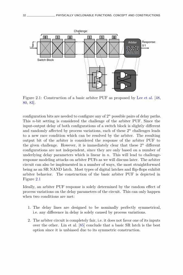
32 PHYSICALLY UNCLONABLE FUNCTIONS: CONCEPT AND CONSTRUCTIONS
0 1 0 0 1 1
Arbiter
Challenge:
Response:
Switch Block
0/1
0
1
0
1
Figure 2.1: Construction of a basic arbiter PUF as proposed by Lee et al. [48,80, 83].
configuration bits are needed to configure any of 2n possible pairs of delay paths.This n-bit setting is considered the challenge of the arbiter PUF. Since theinput-output delay of both configurations of a switch block is slightly differentand randomly affected by process variations, each of these 2n challenges leadsto a new race condition which can be resolved by the arbiter. The resultingoutput bit of the arbiter is considered the response of the arbiter PUF tothe given challenge. However, it is immediately clear that these 2n differentconfigurations are not independent, since they are only based on a number ofunderlying delay parameters which is linear in n. This will lead to challenge-response modeling attacks on arbiter PUFs as we will discuss later. The arbitercircuit can also be implemented in a number of ways, the most straightforwardbeing as an SR NAND latch. Most types of digital latches and flip-flops exhibitarbiter behavior. The construction of the basic arbiter PUF is depicted inFigure 2.1
Ideally, an arbiter PUF response is solely determined by the random effect ofprocess variations on the delay parameters of the circuit. This can only happenwhen two conditions are met:
1. The delay lines are designed to be nominally perfectly symmetrical,i.e. any difference in delay is solely caused by process variations.
2. The arbiter circuit is completely fair, i.e. it does not favor one of its inputsover the other. Lin et al. [85] conclude that a basic SR latch is the bestoption since it is unbiased due to its symmetric construction.
INTRINSIC PUF CONSTRUCTIONS 33
If either of both conditions is not met, the arbiter PUF is biased, whichresults in a lower uniqueness of its responses. Designing a perfectly unbiasedarbiter PUF is highly non-trivial since it requires very low-level control overimplementation choices. In some technologies, e.g. on FPGAs [105], this is notpossible, which greatly impedes the successful deployment of arbiter PUFs onthem. If bias is unavoidable, some unbiasing techniques are possible. A tunabledelay circuit in front of the arbiter PUF can counteract the deterministic biasof the delay paths or the arbiter, e.g. if the arbiter favors the upper delay paththen the tunable delay can give the lower path a head start. A relatively simpleway of doing this is by fixing a number of challenge bits in the beginning of theswitch block chain in such a way as to counteract the bias.
Discussion on Modeling Attacks
The basic arbiter PUF construction with n chained switch blocks allows for 2n
different challenges. However, the number of delay parameters which determinethe arbiter PUF response is only linear in n, which means that these 2n
challenges cannot produce independent responses. In practice, when one learnsthe underlying delay parameters and one can model the interaction with thechallenge bits, one would be able to accurately predict response bits to randomchallenges, even without access to the PUF. In many ways, such a model can beconsidered a clone of the arbiter PUF, be it a mathematical clone. Arbiter PUFresponses are only considered unpredictable as long as such a model cannot beaccurately built.
It was immediately realized by Lee et al. [80] that their basic arbiter PUF canindeed be easily modeled and they even present modeling attack results fortheir own implementation. This and later modeling attacks assume a simplebut accurate additive delay model for the arbiter PUF, i.e. the delay of a digitalcircuit is modeled as the sum of the delays of its serialized components. Thisturns out to be a very accurate first-order approximation for the relativelysimple switch block chains. The unknown underlying delay parameters arelearned from observing challenge-response pairs of the PUF. Every challenge-response pair constitutes a linear inequality over these parameters and isused to obtain a more accurate approximation. Moreover, the unknownparameters do not need to be calculated explicitly, but they are learnedimplicitly and automatically by an appropriate machine-learning technique.Machine-learning techniques such as artificial neural networks (ANN) andsupport-vector machines (SVM) are able to generalize behavior based onapplied examples. Numerous results have been presented which successfullyapply different machine-learning techniques in order to model the behaviorof an arbiter PUF. The ultimate goal of such modeling attacks is to predict
34 PHYSICALLY UNCLONABLE FUNCTIONS: CONCEPT AND CONSTRUCTIONS
unknown responses as accurately as possible after having been trained withas few examples as possible. We say that a PUF is (pmodel, qtrain)-modelable, ifa known modeling attack exists which is able to predict unseen responses ofthe PUF with a success rate pmodel, after training the model with qtrain knownchallenge-response pairs.
Experimental Results and Extended Constructions
Arbiter PUFs were initially implemented by Gassend et al. [48] on a set of23 FPGA devices. From experimental results, the average intra- and inter-distance of the responses were estimated as µintra
P = 0.1% and µinter
P = 1.05%. Theinter-distance is particularly low, with on average only one in 100 challengesproducing a response bit which actually differs between different PUF instances.This arbiter PUF implementation is hence very biased which is a result of thelack of low-level control over the placement and routing of the delay lines onthe FPGA platform. A following implementation by the same team on a setof 37 ASICs proofs to be less biased with µinter
P = 23%, but is still far fromthe ideal of 50%. The reliability of this implementation is very high, withµintra
P = 0.7% under reference conditions. This worsens to µintra
P = 4.82% whentemperature rises to Tenv = 67 °C. Lim [83] demonstrates that this arbiterPUF implementation is (pmodel = 96.45%, qtrain = 5000)-modelable by applyingan SVM-based machine-learning modeling attack. This result is problematicfor this implementation, since the expected prediction error of 100%−96.45% =3.55% is smaller than the average unreliability of the PUF under temperaturevariation. In practice, this means this implementation is not secure (afterobserving qtrain = 5000 challenge-response pairs).
All subsequent work on arbiter PUFs is an attempt to make model-buildingattacks more difficult, by introducing non-linearities in the delays and bycontrolling and/or restricting the inputs and outputs to the PUF. Lee et al.[80] propose feed-forward arbiter PUFs as a first attempt to introduce non-linearities in the delay lines. It is an extension of their basic arbiter PUF, wherethe configuration of some switch blocks in the delay chains is not externallyset by challenge bits, but is determined by the outcome of intermediatearbiters evaluating the race at intermediate points in the delay lines. Thiswas equivalently tested on 37 ASICs leading to µinter
P = 38% and µintra
P = 9.84%(at Tenv = 67 °C). Note that the responses are much noisier, which is causedby the increased metastability since there are multiple arbiters involved. It wasshown that the simple model-building attacks which succeeded in predicting thesimple arbiter don’t work any longer for this non-linear arbiter PUF. However,later results by Majzoobi et al. [99] and Rührmair et al. [123] show that withmore advanced modeling techniques it is still possible to build an accurate
INTRINSIC PUF CONSTRUCTIONS 35
model for the feed-forward arbiter PUF. Based on simulated implementationsof feed-forward arbiter PUFs, Rührmair et al. [123] demonstrate them to be(pmodel > 97.5%, qtrain = 50000)-modelable, with the actual success rate dependingon the delay path length and the number of feed-forward arbiters. Moreadvanced feed-forward architectures are proposed by Lao and Parhi [79].
Majzoobi et al. [100] present an elaborate discussion on techniques to makearbiter-based PUFs on FPGA more resistant to modeling. They use aninitial device characterization step to choose the optimal parameters for aparticular instantiation and use the reconfiguration possibilities of FPGAsto implement this. To increase randomness and to thwart model-buildingattacks, they use “hard-to-invert” input and output networks controlling theinputs and outputs to the PUF, although these are not shown cryptographicallysecure. In particular, they consider multiple arbiter PUFs in parallel and takethe exclusive-or (XOR) of the arbiter evaluations as the new response. Bysimulation, they show that this construction gives desirable PUF propertiesand makes model-building much harder. However, Rührmair et al. [123] againshow that model-building of these elaborate structures might be feasible bypresenting a (pmodel = 99%, qtrain = 6000)-model building attack based on asimulated implementation consisting of n = 64 switch blocks and 3 parallelarbiters which are XOR-ed together. For longer delay paths and more parallelarbiters, this modeling attack keeps on working but requires a considerablelarger qtrain.
Finally, a different approach towards model-building attacks for arbiter PUFsis taken by Öztürk et al. [54, 107, 108]. Instead of preventing the attack,they use the fact that a model of the PUF can be constructed as part of anauthentication protocol. The proposed protocol is a variant of the protocol byHopper and Blum [59], with security based on the difficulty of learning paritywith noise. This is a highly unconventional use of a PUF as it explicitly assumesthe PUF can be cloned mathematically, with the cloned PUF model acting asa noisy shared secret.
2.4.2 Ring Oscillator PUF
Basic Operation and Construction
A second type of delay-based intrinsic PUFs are ring oscillator PUFs. A numberof different constructions can be placed under this type, all based on measuringrandom variations on the frequencies of digital oscillating circuits. The sourceof this randomness is again the uncontrollable effect of silicon process variationson the delay of digital components. When these components constitute a ring
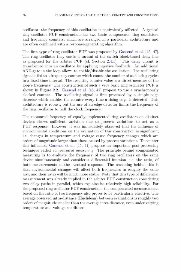
36 PHYSICALLY UNCLONABLE FUNCTIONS: CONCEPT AND CONSTRUCTIONS
oscillator, the frequency of this oscillation is equivalently affected. A typicalring oscillator PUF construction has two basic components, ring oscillatorsand frequency counters, which are arranged in a particular architecture andare often combined with a response-generating algorithm.
The first type of ring oscillator PUF was proposed by Gassend et al. [45, 47].The ring oscillator they use is a variant of the switch block-based delay lineas proposed for the arbiter PUF (cf. Section 2.4.1). This delay circuit istransformed into an oscillator by applying negative feedback. An additionalAND-gate in the loop allows to enable/disable the oscillation. The oscillatingsignal is fed to a frequency counter which counts the number of oscillating cyclesin a fixed time interval. The resulting counter value is a direct measure of theloop’s frequency. The construction of such a very basic ring oscillator PUF isshown in Figure 2.2. Gassend et al. [45, 47] propose to use a synchronouslyclocked counter. The oscillating signal is first processed by a simple edgedetector which enables the counter every time a rising edge is detected. Thisarchitecture is robust, but the use of an edge detector limits the frequency ofthe ring oscillator to half the clock frequency.
The measured frequency of equally implemented ring oscillators on distinctdevices shows sufficient variation due to process variations to act as aPUF response. However, it was immediately observed that the influence ofenvironmental conditions on the evaluation of this construction is significant,i.e. changes in temperature and voltage cause frequency changes which areorders of magnitude larger than those caused by process variations. To counterthis influence, Gassend et al. [45, 47] propose an important post-processingtechnique called compensated measuring. The principle behind compensatedmeasuring is to evaluate the frequency of two ring oscillators on the samedevice simultaneously and consider a differential function, i.c. the ratio, ofboth measurements as the eventual response. The reasoning behind this isthat environmental changes will affect both frequencies in roughly the sameway, and their ratio will be much more stable. Note that this type of differentialmeasurement was already implied in the arbiter PUF construction consideringtwo delay paths in parallel, which explains its relatively high reliability. Forthe proposed ring oscillator PUF construction, the compensated measurementsbased on the ratio of two frequency also proves to be particularly effective. Theaverage observed intra-distance (Euclidean) between evaluations is roughly twoorders of magnitude smaller than the average inter-distance, even under varyingtemperature and voltage conditions.
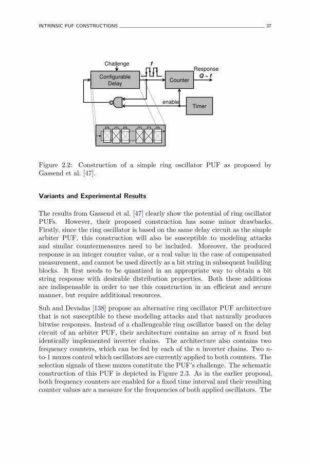
INTRINSIC PUF CONSTRUCTIONS 37
Configurable
Delay
Challenge
Counter
Timer enable
f
Q ~ f
Response
0 1 0 0 1 1
Figure 2.2: Construction of a simple ring oscillator PUF as proposed byGassend et al. [47].
Variants and Experimental Results
The results from Gassend et al. [47] clearly show the potential of ring oscillatorPUFs. However, their proposed construction has some minor drawbacks.Firstly, since the ring oscillator is based on the same delay circuit as the simplearbiter PUF, this construction will also be susceptible to modeling attacksand similar countermeasures need to be included. Moreover, the producedresponse is an integer counter value, or a real value in the case of compensatedmeasurement, and cannot be used directly as a bit string in subsequent buildingblocks. It first needs to be quantized in an appropriate way to obtain a bitstring response with desirable distribution properties. Both these additionsare indispensable in order to use this construction in an efficient and securemanner, but require additional resources.
Suh and Devadas [138] propose an alternative ring oscillator PUF architecturethat is not susceptible to these modeling attacks and that naturally producesbitwise responses. Instead of a challengeable ring oscillator based on the delaycircuit of an arbiter PUF, their architecture contains an array of n fixed butidentically implemented inverter chains. The architecture also contains twofrequency counters, which can be fed by each of the n inverter chains. Two n-to-1 muxes control which oscillators are currently applied to both counters. Theselection signals of these muxes constitute the PUF’s challenge. The schematicconstruction of this PUF is depicted in Figure 2.3. As in the earlier proposal,both frequency counters are enabled for a fixed time interval and their resultingcounter values are a measure for the frequencies of both applied oscillators. The
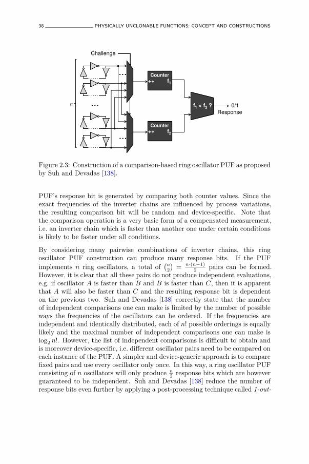
38 PHYSICALLY UNCLONABLE FUNCTIONS: CONCEPT AND CONSTRUCTIONS
...
Counter
++ f1
Counter
++ f2
...
...
f1 < f2 ?
Challenge
Response
0/1 n
Figure 2.3: Construction of a comparison-based ring oscillator PUF as proposedby Suh and Devadas [138].
PUF’s response bit is generated by comparing both counter values. Since theexact frequencies of the inverter chains are influenced by process variations,the resulting comparison bit will be random and device-specific. Note thatthe comparison operation is a very basic form of a compensated measurement,i.e. an inverter chain which is faster than another one under certain conditionsis likely to be faster under all conditions.
By considering many pairwise combinations of inverter chains, this ringoscillator PUF construction can produce many response bits. If the PUFimplements n ring oscillators, a total of
(n2
)= n·(n−1)
2 pairs can be formed.However, it is clear that all these pairs do not produce independent evaluations,e.g. if oscillator A is faster than B and B is faster than C, then it is apparentthat A will also be faster than C and the resulting response bit is dependenton the previous two. Suh and Devadas [138] correctly state that the numberof independent comparisons one can make is limited by the number of possibleways the frequencies of the oscillators can be ordered. If the frequencies areindependent and identically distributed, each of n! possible orderings is equallylikely and the maximal number of independent comparisons one can make islog2 n!. However, the list of independent comparisons is difficult to obtain andis moreover device-specific, i.e. different oscillator pairs need to be compared oneach instance of the PUF. A simpler and device-generic approach is to comparefixed pairs and use every oscillator only once. In this way, a ring oscillator PUFconsisting of n oscillators will only produce n
2 response bits which are howeverguaranteed to be independent. Suh and Devadas [138] reduce the number ofresponse bits even further by applying a post-processing technique called 1-out-
INTRINSIC PUF CONSTRUCTIONS 39
of-k masking, i.e. they evaluate k oscillators and only consider the pair withthe largest difference in frequency and output the result of this comparison.This technique greatly enhances the reliability of the responses, but it comes ata relatively large resource overhead, i.e. out of n oscillators only ⌊n
k⌋ response
bits are generated. Experiments on a set of 15 FPGAs with k = 8 produceresponses with an average inter-distance of 46.15% and a very low averageintra-distance of merely 0.48% even under large temperature (Tenv = 120 °C)and voltage (Vdd + 10%) variations.
Maiti et al. [95] present results from a large scale characterization of the ringoscillator PUF construction from Suh and Devadas [138] on FPGA. They do notapply the masking technique, but instead compare all neighbouring oscillatorson the FPGA, yielding n − 1 response bits from n oscillators. Their resultsare particularly valuable as they are based on a large population of devices(125 FPGAs), which is rare in other works on PUFs. They present an averageinter-distance of 47.31% and an average intra-distance of 0.86% at nominalconditions. However, changing temperature and especially voltage conditionshave a significant impact on the intra-distance. At a 20% reduced supplyvoltage, the average intra-distance goes up to 15%. The measurement dataresulting from this experiment is made publicly available [3].
Yin and Qu [158] build upon the construction from Suh and Devadas [138]and propose a number of adaptations which significantly improve the resourceusage of the ring oscillator PUF. Firstly, they propose a generalization of the1-out-of-k masking scheme which is much less aggressive in ignoring oscillatorsbut achieves similar reliability results. The group of oscillators is partitioned inmutually exclusive subsets such that the minimal frequency difference betweentwo members of a subset is above a certain threshold. An evaluation between apair of oscillators from the same subset is therefore guaranteed to be very stable.Yet by using a clever grouping algorithm, practically all oscillators constituteto a response bit and only a few are ignored. Secondly, they propose a hybridarchitecture for arranging ring oscillators and frequency counters. This allowsto find an optimal trade-off between the speed of generating responses and theresource usage of oscillators, counters and multiplexers.
Maiti and Schaumont [97, 98] also expand upon the construction from Suhand Devadas [138] and present some significant improvements. Firstly, theypropose a number of guidelines for reducing systematic bias when implementingarrays of ring oscillators on an FPGA, and study the effect of each guidelineon the uniqueness of the responses. Secondly, they propose a very efficient buthighly effective variant of the 1-out-of-k masking scheme based on configurablering oscillators. Instead of considering the most reliable pair out of k distinctoscillators, they make use of the oscillators’ configurability and consider themost reliable out of k configurations of a single pair of oscillators. This
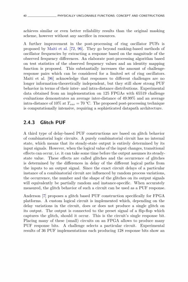
40 PHYSICALLY UNCLONABLE FUNCTIONS: CONCEPT AND CONSTRUCTIONS
achieves similar or even better reliability results than the original maskingscheme, however without any sacrifice in resources.
A further improvement in the post-processing of ring oscillator PUFs isproposed by Maiti et al. [72, 96]. They go beyond ranking-based methods ofoscillator frequencies by extracting a response based on the magnitude of theobserved frequency differences. An elaborate post-processing algorithm basedon test statistics of the observed frequency values and an identity mappingfunction is proposed. This substantially increases the amount of challenge-response pairs which can be considered for a limited set of ring oscillators.Maiti et al. [96] acknowledge that responses to different challenges are nolonger information-theoretically independent, but they still show strong PUFbehavior in terms of their inter- and intra-distance distributions. Experimentaldata obtained from an implementation on 125 FPGAs with 65519 challengeevaluations demonstrates an average inter-distance of 49.99% and an averageintra-distance of 10% at Tenv = 70 °C. The proposed post-processing techniqueis computationally intensive, requiring a sophisticated datapath architecture.
2.4.3 Glitch PUF
A third type of delay-based PUF constructions are based on glitch behaviorof combinatorial logic circuits. A purely combinatorial circuit has no internalstate, which means that its steady-state output is entirely determined by itsinput signals. However, when the logical value of the input changes, transitionaleffects can occur, i.e. it can take some time before the output assumes its steady-state value. These effects are called glitches and the occurrence of glitchesis determined by the differences in delay of the different logical paths fromthe inputs to an output signal. Since the exact circuit delays of a particularinstance of a combinatorial circuit are influenced by random process variations,the occurrence, the number and the shape of the glitches on its output signalswill equivalently be partially random and instance-specific. When accuratelymeasured, the glitch behavior of such a circuit can be used as a PUF response.
Anderson [7] proposes a glitch based PUF construction specifically for FPGAplatforms. A custom logical circuit is implemented which, depending on thedelay variations in the circuit, does or does not produce a single glitch onits output. The output is connected to the preset signal of a flip-flop whichcaptures the glitch, should it occur. This is the circuit’s single response bit.Placing many of these (small) circuits on an FPGA allows to produce manyPUF response bits. A challenge selects a particular circuit. Experimentalresults of 36 PUF implementations each producing 128 response bits show an
INTRINSIC PUF CONSTRUCTIONS 41
average inter-distance of 48.3% and an average intra-distance of 3.6% underhigh temperature conditions (Tenv = 70 °C).
Shimizu et al. [133, 139] present a more elaborate glitch PUF constructionand also introduce the term glitch PUF. They propose a methodology touse the glitch behavior of any combinatorial circuit as a PUF response andapply it specifically to a combinatorial FPGA implementation of the SubBytesoperation of AES [34]. Their initial proposal [139] consists of an elaboratearchitecture which performs an on-chip high-frequency sampling of the glitchwave form and a quantization circuit which generates a response bit basedon the sampled data. They propose to use the parity of the number ofdetected glitches as a random yet robust feature of a glitch wave form. Ina later version of their PUF construction [133], they propose a much simplerimplementation which achieves basically the same functionality and results. Bysimply connecting a combinatorial output to a toggle flip-flop, the value of thetoggle flip-flop after the transitional phase will equal the parity of the numberof glitches that occurred. This construction is shown in Figure 2.4. To improvethe reliability of the PUF responses, a bit-masking technique is used. Duringan initial measurement on every instance, unstable response bits are identifiedas responses that do not produce a stable value on m consecutive evaluations.In later measurements, these response bits are ignored, i.e. they are masked.The mask information needs to be stored alongside each PUF instance or inan external storage. This type of masking also causes a resource overhead,as the identified unstable bits are not used in the PUF responses. However,the resulting unmasked bits show a greatly improved reliability. Experimentalresults from 16 FPGA implementations of this glitch PUF construction on 2048challenges show an average inter-distance of 35% and an average intra-distanceof 1.3% at nominal conditions, when bit-masking is applied. The bit-maskingresults in about 38% of the response bits being ignored. Under variations of theenvironmental conditions, the average intra-distance increases substantially, toabout 15% in the worst-case corner condition of Tenv = 85 °C and Vdd + 5%.
2.4.4 SRAM PUF
SRAM Background
Static Random-Access Memory or SRAM is a digital memory technology basedon bistable circuits. In a typical CMOS implementation, an individual SRAMcell is built with six transistors (MOSFETs), as shown in Figure 2.5a. Thelogic memory functionality of a cell comes from two cross-coupled inverters atits core, shown in Figure 2.5b, each built from two MOSFETs, one p-MOSand one n-MOS. From an electronic viewpoint, this circuit contains a positive
42 PHYSICALLY UNCLONABLE FUNCTIONS: CONCEPT AND CONSTRUCTIONS
Combinatorial Logic
e.g. AES S-box
Input Register
Toggle Flip-flop
Glitch waveform
#glitches = odd
² Response = 1
#glitches = even
² Response = 0
Challenge =
input (transition)
Figure 2.4: Construction of a glitch PUF as proposed by Shimizu et al. [133].
feedback loop which reinforces its current state. In a logic sense, this circuithas two stable values (bistable), and by residing in one of both states the cellstores one binary digit. Two additional access MOSFETs are used to read andwrite its contents. Typically, many SRAM cells are arranged in large memoryarray structures, capable of storing many kilobits or megabits. An SRAM cellis volatile meaning that its state is lost shortly after power down.
The detailed operation of an SRAM cell is best explained by drawing the voltagetransfer curves of the two cross-coupled inverters, shown in Figure 2.5c. Fromthis graph, it is clear that the cross-coupled CMOS inverter structure has threepossible operating points of which only two are stable and one is metastable.The stable points are characterized by the property that deviations from thesepoints are reduced and the stable point condition is restored. This does nothold for the metastable point, i.e. any small deviation from the metastable pointis immediately amplified by the positive feedback and the circuit moves awayfrom the metastable point towards one of both stable points. Since electroniccircuits are constantly affected by small deviations due to random noise, anSRAM cell will never stay in its metastable state very long but will quickly endup in one of both stable states (randomly).
Basic Operation
The operation principle of an SRAM PUF is based on the transient behavior ofan SRAM cell when it is powered up, i.e. when its supply voltage Vdd comes up.The circuit will evolve to one of its operating points, but it is not immediatelyclear to which one. The preferred initial operating point of an SRAM cell isdetermined by the difference in ‘strength’ of the MOSFETs in the cross-coupledinverter circuit. The transient behavior of an SRAM cell at power-up is shownin Figure 2.5d. For efficiency and performance reasons, typical SRAM cells are
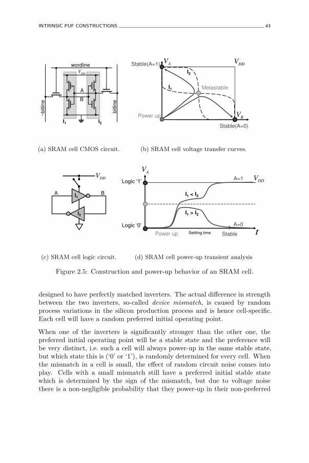
INTRINSIC PUF CONSTRUCTIONS 43
DDV
A
B
wordline
bitlin
e
~b
itlin
e
I1 I2
(a) SRAM cell CMOS circuit.
AV
BV
DDVStable(A=1)
Stable(A=0)
Metastable
Power up
I1
I2
(b) SRAM cell voltage transfer curves.
DDV
A B I1
I2
(c) SRAM cell logic circuit.
Power up Stable Settling time
I1 < I2
I1 > I2
AV
t
/RJLF�µ�
/RJLF�µ�
DDVA=1
A=0
(d) SRAM cell power-up transient analysis
Figure 2.5: Construction and power-up behavior of an SRAM cell.
designed to have perfectly matched inverters. The actual difference in strengthbetween the two inverters, so-called device mismatch, is caused by randomprocess variations in the silicon production process and is hence cell-specific.Each cell will have a random preferred initial operating point.
When one of the inverters is significantly stronger than the other one, thepreferred initial operating point will be a stable state and the preference willbe very distinct, i.e. such a cell will always power-up in the same stable state,but which state this is (‘0’ or ‘1’), is randomly determined for every cell. Whenthe mismatch in a cell is small, the effect of random circuit noise comes intoplay. Cells with a small mismatch still have a preferred initial stable statewhich is determined by the sign of the mismatch, but due to voltage noisethere is a non-negligible probability that they power-up in their non-preferred
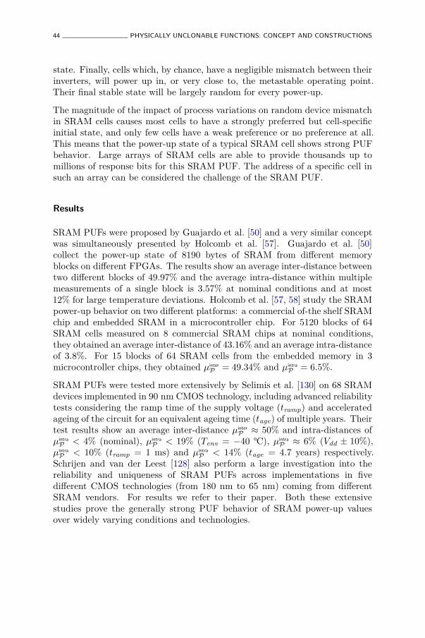
44 PHYSICALLY UNCLONABLE FUNCTIONS: CONCEPT AND CONSTRUCTIONS
state. Finally, cells which, by chance, have a negligible mismatch between theirinverters, will power up in, or very close to, the metastable operating point.Their final stable state will be largely random for every power-up.
The magnitude of the impact of process variations on random device mismatchin SRAM cells causes most cells to have a strongly preferred but cell-specificinitial state, and only few cells have a weak preference or no preference at all.This means that the power-up state of a typical SRAM cell shows strong PUFbehavior. Large arrays of SRAM cells are able to provide thousands up tomillions of response bits for this SRAM PUF. The address of a specific cell insuch an array can be considered the challenge of the SRAM PUF.
Results
SRAM PUFs were proposed by Guajardo et al. [50] and a very similar conceptwas simultaneously presented by Holcomb et al. [57]. Guajardo et al. [50]collect the power-up state of 8190 bytes of SRAM from different memoryblocks on different FPGAs. The results show an average inter-distance betweentwo different blocks of 49.97% and the average intra-distance within multiplemeasurements of a single block is 3.57% at nominal conditions and at most12% for large temperature deviations. Holcomb et al. [57, 58] study the SRAMpower-up behavior on two different platforms: a commercial of-the shelf SRAMchip and embedded SRAM in a microcontroller chip. For 5120 blocks of 64SRAM cells measured on 8 commercial SRAM chips at nominal conditions,they obtained an average inter-distance of 43.16% and an average intra-distanceof 3.8%. For 15 blocks of 64 SRAM cells from the embedded memory in 3microcontroller chips, they obtained µinter
P = 49.34% and µintra
P = 6.5%.
SRAM PUFs were tested more extensively by Selimis et al. [130] on 68 SRAMdevices implemented in 90 nm CMOS technology, including advanced reliabilitytests considering the ramp time of the supply voltage (tramp) and acceleratedageing of the circuit for an equivalent ageing time (tage) of multiple years. Theirtest results show an average inter-distance µinter
P ≈ 50% and intra-distances ofµintra
P < 4% (nominal), µintra
P < 19% (Tenv = −40 °C), µintra
P ≈ 6% (Vdd ± 10%),µintra
P < 10% (tramp = 1 ms) and µintra
P < 14% (tage = 4.7 years) respectively.Schrijen and van der Leest [128] also perform a large investigation into thereliability and uniqueness of SRAM PUFs across implementations in fivedifferent CMOS technologies (from 180 nm to 65 nm) coming from differentSRAM vendors. For results we refer to their paper. Both these extensivestudies prove the generally strong PUF behavior of SRAM power-up valuesover widely varying conditions and technologies.
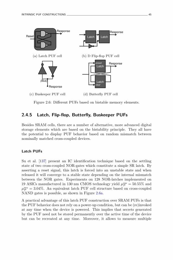
INTRINSIC PUF CONSTRUCTIONS 45
Reset
Response
(a) Latch PUF cell
Latch Latch
Response
(b) D Flip-flop PUF cell
(Bus)
Response
(c) Buskeeper PUF cell
Latch
Latch
preset
clear
Response
(d) Butterfly PUF cell
Figure 2.6: Different PUFs based on bistable memory elements.
2.4.5 Latch, Flip-flop, Butterfly, Buskeeper PUFs
Besides SRAM cells, there are a number of alternative, more advanced digitalstorage elements which are based on the bistability principle. They all havethe potential to display PUF behavior based on random mismatch betweennominally matched cross-coupled devices.
Latch PUFs
Su et al. [137] present an IC identification technique based on the settlingstate of two cross-coupled NOR-gates which constitute a simple SR latch. Byasserting a reset signal, this latch is forced into an unstable state and whenreleased it will converge to a stable state depending on the internal mismatchbetween the NOR gates. Experiments on 128 NOR-latches implemented on19 ASICs manufactured in 130 nm CMOS technology yield µinter
P = 50.55% andµintra
P = 3.04%. An equivalent latch PUF cell structure based on cross-coupledNAND gates is possible, as shown in Figure 2.6a.
A practical advantage of this latch PUF construction over SRAM PUFs is thatthe PUF behavior does not rely on a power-up condition, but can be (re)invokedat any time when the device is powered. This implies that secrets generatedby the PUF need not be stored permanently over the active time of the devicebut can be recreated at any time. Moreover, it allows to measure multiple
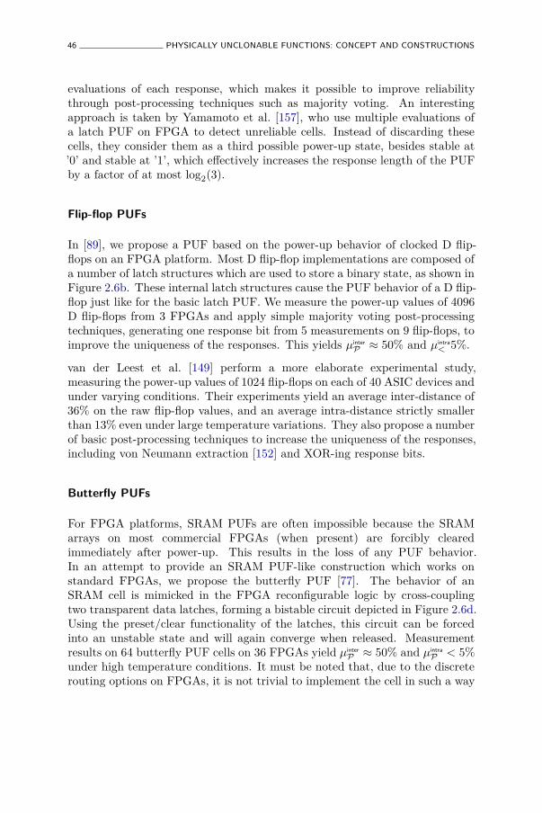
46 PHYSICALLY UNCLONABLE FUNCTIONS: CONCEPT AND CONSTRUCTIONS
evaluations of each response, which makes it possible to improve reliabilitythrough post-processing techniques such as majority voting. An interestingapproach is taken by Yamamoto et al. [157], who use multiple evaluations ofa latch PUF on FPGA to detect unreliable cells. Instead of discarding thesecells, they consider them as a third possible power-up state, besides stable at’0’ and stable at ’1’, which effectively increases the response length of the PUFby a factor of at most log2(3).
Flip-flop PUFs
In [89], we propose a PUF based on the power-up behavior of clocked D flip-flops on an FPGA platform. Most D flip-flop implementations are composed ofa number of latch structures which are used to store a binary state, as shown inFigure 2.6b. These internal latch structures cause the PUF behavior of a D flip-flop just like for the basic latch PUF. We measure the power-up values of 4096D flip-flops from 3 FPGAs and apply simple majority voting post-processingtechniques, generating one response bit from 5 measurements on 9 flip-flops, toimprove the uniqueness of the responses. This yields µinter
P ≈ 50% and µintra< 5%.
van der Leest et al. [149] perform a more elaborate experimental study,measuring the power-up values of 1024 flip-flops on each of 40 ASIC devices andunder varying conditions. Their experiments yield an average inter-distance of36% on the raw flip-flop values, and an average intra-distance strictly smallerthan 13% even under large temperature variations. They also propose a numberof basic post-processing techniques to increase the uniqueness of the responses,including von Neumann extraction [152] and XOR-ing response bits.
Butterfly PUFs
For FPGA platforms, SRAM PUFs are often impossible because the SRAMarrays on most commercial FPGAs (when present) are forcibly clearedimmediately after power-up. This results in the loss of any PUF behavior.In an attempt to provide an SRAM PUF-like construction which works onstandard FPGAs, we propose the butterfly PUF [77]. The behavior of anSRAM cell is mimicked in the FPGA reconfigurable logic by cross-couplingtwo transparent data latches, forming a bistable circuit depicted in Figure 2.6d.Using the preset/clear functionality of the latches, this circuit can be forcedinto an unstable state and will again converge when released. Measurementresults on 64 butterfly PUF cells on 36 FPGAs yield µinter
P ≈ 50% and µintra
P < 5%under high temperature conditions. It must be noted that, due to the discreterouting options on FPGAs, it is not trivial to implement the cell in such a way
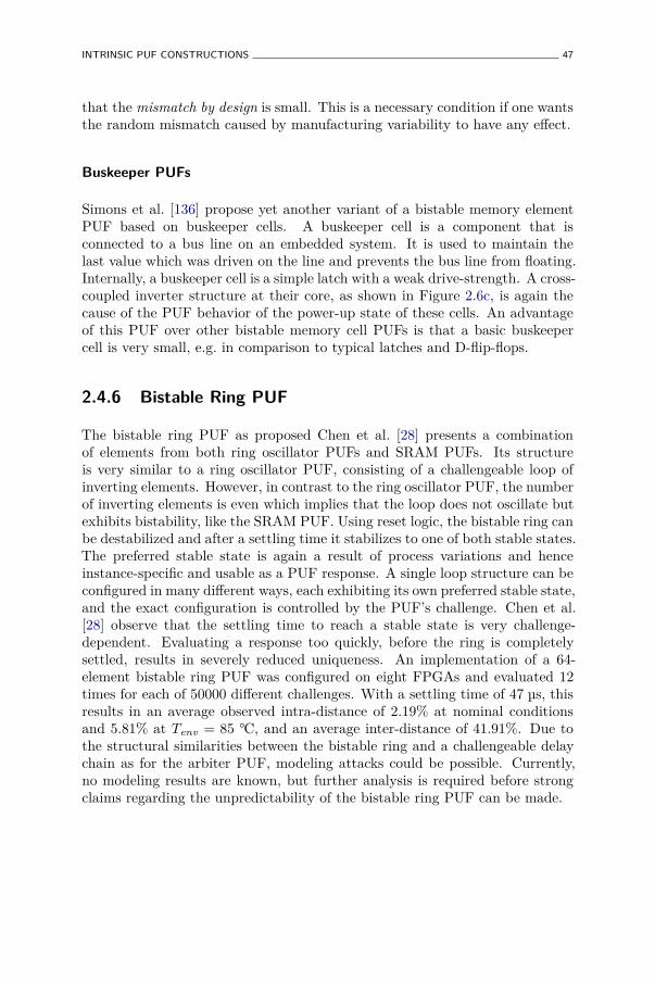
INTRINSIC PUF CONSTRUCTIONS 47
that the mismatch by design is small. This is a necessary condition if one wantsthe random mismatch caused by manufacturing variability to have any effect.
Buskeeper PUFs
Simons et al. [136] propose yet another variant of a bistable memory elementPUF based on buskeeper cells. A buskeeper cell is a component that isconnected to a bus line on an embedded system. It is used to maintain thelast value which was driven on the line and prevents the bus line from floating.Internally, a buskeeper cell is a simple latch with a weak drive-strength. A cross-coupled inverter structure at their core, as shown in Figure 2.6c, is again thecause of the PUF behavior of the power-up state of these cells. An advantageof this PUF over other bistable memory cell PUFs is that a basic buskeepercell is very small, e.g. in comparison to typical latches and D-flip-flops.
2.4.6 Bistable Ring PUF
The bistable ring PUF as proposed Chen et al. [28] presents a combinationof elements from both ring oscillator PUFs and SRAM PUFs. Its structureis very similar to a ring oscillator PUF, consisting of a challengeable loop ofinverting elements. However, in contrast to the ring oscillator PUF, the numberof inverting elements is even which implies that the loop does not oscillate butexhibits bistability, like the SRAM PUF. Using reset logic, the bistable ring canbe destabilized and after a settling time it stabilizes to one of both stable states.The preferred stable state is again a result of process variations and henceinstance-specific and usable as a PUF response. A single loop structure can beconfigured in many different ways, each exhibiting its own preferred stable state,and the exact configuration is controlled by the PUF’s challenge. Chen et al.[28] observe that the settling time to reach a stable state is very challenge-dependent. Evaluating a response too quickly, before the ring is completelysettled, results in severely reduced uniqueness. An implementation of a 64-element bistable ring PUF was configured on eight FPGAs and evaluated 12times for each of 50000 different challenges. With a settling time of 47 µs, thisresults in an average observed intra-distance of 2.19% at nominal conditionsand 5.81% at Tenv = 85 °C, and an average inter-distance of 41.91%. Due tothe structural similarities between the bistable ring and a challengeable delaychain as for the arbiter PUF, modeling attacks could be possible. Currently,no modeling results are known, but further analysis is required before strongclaims regarding the unpredictability of the bistable ring PUF can be made.

48 PHYSICALLY UNCLONABLE FUNCTIONS: CONCEPT AND CONSTRUCTIONS
Tab
le2.
1:O
verv
iew
ofex
per
imen
tal
resu
lts
ofin
trin
sic
PU
Fco
nstr
ucti
ons
inth
elit
erat
ure.
In
trin
sic
PU
FP
ro
po
sa
lP
Ex
perim
en
tD
eta
ils
Ex
perim
en
tR
esu
lts
Co
nd
itio
nα
Npuf
Nch
al
Nm
eas
µin
ter
Pµ
intr
aP
;α
Sim
ple
Arb
iter
PU
F[4
8]
nom
inal
23
(FP
GA
)100000
200
0.1
0%
1.0
5%
Sim
ple
Arb
iter
PU
F[4
8]
Ten
v=
60
°C23
(FP
GA
)100000
23
0.3
0%
1.0
5%
Sim
ple
Arb
iter
PU
F[ 8
0]
nom
inal
37
(AS
IC)
10000
?0.7
0%
23.0
0%
Sim
ple
Arb
iter
PU
F[8
0]
Ten
v=
67
°C37
(AS
IC)
10000
?4.8
2%
23.0
0%
Sim
ple
Arb
iter
PU
F[8
0]
Vd
d−
2%
37
(AS
IC)
10000
?3.7
4%
23.0
0%
FF
Arb
iter
PU
F[8
4]
nom
inal
20
(AS
IC)
100000
?4.5
0%
38.0
0%
FF
Arb
iter
PU
F[ 8
4]
Ten
v=
67
°C20
(AS
IC)
100000
?9.8
4%
38.0
0%
Basi
cR
OP
UF
[47]
Ten
v=
50
°C4
(FP
GA
)?
?0.0
1%
1.0
0%
RO
PU
F[1
38]
Ten
v=
120
°C&
Vd
d+
10%
15
(FP
GA
)128
?0.4
8%
46.1
5%
RO
PU
F[ 9
5]
nom
inal
125
(FP
GA
)511
100
0.8
6%
47.1
3%
RO
PU
F[9
5]
Ten
v=
65
°C5
(FP
GA
)511
100
4.0
0%
47.1
3%
RO
PU
F[9
5]
Vd
d−
20%
5(F
PG
A)
511
100
15.0
0%
47.1
3%
Imp
roved
RO
PU
F[ 9
8]
nom
inal
5(F
PG
A)
255
?0.0
0%
44.1
0%
Imp
roved
RO
PU
F[9
8]
Ten
v=
65
°C5
(FP
GA
)255
?0.0
0%
44.1
0%
Imp
roved
RO
PU
F[9
8]
Vd
d−
20%
5(F
PG
A)
255
?2.0
0%
44.1
0%
En
han
ced
RO
PU
F[9
6]
Ten
v=
70
°C125
(FP
GA
)65519
?49.9
9%
10%
Gli
tch
PU
F[ 7
]T
en
v=
70
°C36
(FP
GA
)128
?3.6
0%
48.3
0%
Gli
tch
PU
F[1
33]
nom
inal
16
(FP
GA
)2048
?1.3
0%
35.0
0%
Gli
tch
PU
F[1
33]
Ten
v=
85
°C&
Vd
d+
5%
16
(FP
GA
)2048
?15.0
0%
35.0
0%
SR
AM
PU
F[ 5
0]
nom
inal
?(F
PG
A)
8190
92
3.5
7%
49.9
7%
SR
AM
PU
F[5
0]
Ten
v=
80
°C?
(FP
GA
)8190
?12.0
0%
49.9
7%
SR
AM
PU
F[5
8]
nom
inal
5120
(CO
TS
)64
?3.8
0%
43.1
6%
SR
AM
PU
F[5
8]
nom
inal
15
(µC
)64
?6.5
0%
49.3
4%
SR
AM
PU
F[ 1
30]
nom
inal
68
(AS
IC)
2048
?<
4%
≈50.0
0%
(con
tin
ues
on
nex
tpa
ge)
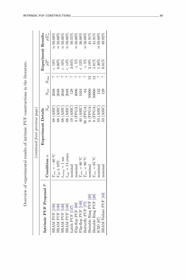
INTRINSIC PUF CONSTRUCTIONS 49
Ove
rvie
wof
exp
erim
enta
lre
sult
sof
intr
insi
cP
UF
cons
truc
tion
sin
the
liter
atur
e.
(con
tin
ued
from
pre
vious
page
)
In
trin
sic
PU
FP
ro
po
sa
lP
Ex
perim
en
tD
eta
ils
Ex
perim
en
tR
esu
lts
Co
nd
itio
nα
Npuf
Nch
al
Nm
eas
µin
ter
Pµ
intr
aP
;α
SR
AM
PU
F[1
30]
Ten
v=
−40
°C68
(AS
IC)
2048
?<
19%
≈50.0
0%
SR
AM
PU
F[1
30]
Vd
d±
10%
68
(AS
IC)
2048
?6.0
0%
≈50.0
0%
SR
AM
PU
F[1
30]
t ra
mp
=1
ms
68
(AS
IC)
2048
?<
10%
≈50.0
0%
SR
AM
PU
F[ 1
30]
t age
=14
yea
rs68
(AS
IC)
2048
?<
14%
≈50.0
0%
Latc
hP
UF
[137]
nom
inal
19
(AS
IC)
128
?3.0
4%
50.5
5%
Fli
p-fl
op
PU
F[8
9]
nom
inal
3(F
PG
A)
4096
?<
5%
≈50.0
0%
Fli
p-fl
op
PU
F[ 1
49]
Ten
v=
80
°C40
(AS
IC)
1024
?<
13%
36.0
0%
Bu
tter
fly
PU
F[7
7]
Ten
v=
80
°C36
(FP
GA
)64
?<
5%
≈50.0
0%
Bis
tab
leR
ing
PU
F[2
8]
nom
inal
8(F
PG
A)
50000
12
2.1
9%
41.9
1%
Bis
tab
leR
ing
PU
F[2
8]
Ten
v=
85
°C8
(FP
GA
)50000
12
5.8
1%
41.9
1%
ICID
[ 87]
nom
inal
55
(AS
IC)
132
?1.3
0%
≈50.0
0%
SR
AM
Fail
ure
PU
F[4
3]
nom
inal
53
(AS
IC)
128
?0.0
1%
49.9
2%
50 PHYSICALLY UNCLONABLE FUNCTIONS: CONCEPT AND CONSTRUCTIONS
2.4.7 Mixed-Signal PUF Constructions
Next, we describe a number of integrated electronic PUF proposals whosePUF behavior is inherently of an analog nature. This means that they alsorequire embedded analog measurement techniques, and an analog-to-digitalconversion if their responses are required in digital form, making them mixed-signal electronic constructions. While technically labelled as intrinsic PUFs,since they can be integrated on a silicon die and take their randomness fromprocess variations, it is not straightforward to deploy these constructions in astandard digital silicon circuit, due to their mixed-signal nature and possiblydue to non-standard manufacturing processes.
ICID: A Threshold Voltage PUF
To the best of our knowledge, Lofstrom et al. [87] were the first to propose anembedded technique called ICID which measures implicit process variations onintegrated circuits and use them as unique identifier of the embedding silicondie. Their construction consists of a number of equally designed transistorslaid out in an addressable array. The addressed transistor drives a resistiveload and because of the effect of random process variations on the thresholdvoltages of these transistors, the current through this load will be partiallyrandom. The voltage over the load is measured and converted to a bit stringwith an auto-zeroing comparator. The technique was experimentally verifiedon 55 ASICs produced in 350 nm CMOS technology. An average intra-distanceunder extreme environmental variations of µintra
P = 1.3% is observed, while µinter
P
is very close to 50%.
Inverter Gain PUF
Puntin et al. [111] present a PUF construction based on the variable gain ofequally designed inverters, caused by process variations. The difference in gainbetween a pair of inverters is determined in an analog electronic measurementand converted into a single bit response. The proposed construction isimplemented in 90 nm CMOS and an experimentally observed average intra-distance < 0.07% at nominal conditions and < 0.4% at (Tenv = 125 °C, Vdd +10%) is reported, however this already includes a masking of the 20% leaststable response bits. The inter-distance is not presented, but it is mentionedthat the correlation between response strings from different PUF instances isless than 1%.
INTRINSIC PUF CONSTRUCTIONS 51
SHIC PUFs
Rührmair et al. [121, 122] propose a circuit consisting of an addressable array ofdiodes which is implemented as a crossbar memory in the aluminium-inducedlayer exchange (ALILE) technology. They observe that the read-out time ofeach memory cell, consisting of a single diode, is influenced by process variationsand hence usable as a PUF response. Since each crosspoint in a dense grid ofmetal lines creates a diode, a very high physical density of response bits of up to1010bit/cm2 can be obtained, hence the name Super-High Information Contentor SHIC PUF. The performance of the construction is very low, allowing read-out speeds of merely 100 bit/s. The authors claim that the combination ofhigh density and low performance provides protection against full read-outattacks, but it is unclear whether the particularly low performance allows forany practical application. The physical mechanisms to produce such a SHICPUF were tested, but no experimental PUF data is provided.
SRAM Failure PUF
An SRAM PUF variant is proposed by Fujiwara et al. [43]. The static noisemargin (SNM) of an SRAM cell is a key figure of merit describing the resistanceof a cell to voltage noise. Voltage noise exceeding the SNM alters a cell’s stateand hence deletes the information it is storing, resulting in a bit failure. Theexact value of a cell’s SNM is also influenced by silicon process variations, henceeach cell in an SRAM array will produce a bit failure at a slightly differentnoise level. Fujiwara et al. [43] apply this observation to build a PUF. Bygradually increasing the word line voltage of an SRAM array, the SNM of acell is reduced until it produces a bit failure. They do this for a large arrayof cells and identify the first n failing cells. The addresses of these cells arerandom and are used as the PUFs response. They present experimental resultsfrom 53 test ASICs each producing 128 response bits and report an averageinter-distance of 49.92%. The average observed intra-distance is as low as 0.1%,but this is already after an elaborate majority voting post-processing. A verysimilar concept is proposed by Krishna et al. [75] as the MECCA PUF. Theyshorten the word line duty cycle of the SRAM array to induce failures.
2.4.8 Overview of Experimental Results
Table 2.1 summarizes all experimental results on intrinsic PUF constructionsthat are discussed in this section. We compare the average response intra-and inter-distances of the proposals since they are the most important quality
52 PHYSICALLY UNCLONABLE FUNCTIONS: CONCEPT AND CONSTRUCTIONS
parameters of a PUF and are therefore nearly always mentioned for a PUFexperiment. When possible, we also mention the details of the experimentwhich produced these statistics, i.e. the condition under which the experimentwas performed (α), and the size of the experiment in terms of number ofdifferent PUF instances (Npuf), number of challenges measured per instance(Nchal), and number of evaluations of each challenge (Nmeas).
Although the intra- and inter-distance mean gives a good first notion of thequality of a PUF, there are a number of other measures which need to beconsidered when objectively comparing different PUF proposals. For one,the PUF proposals listed in Table 2.1 represent a wide variety of differentimplementations. Besides the basic PUF quality, the implementation efficiencyand performance are equally important for most applications. However,for many PUF constructions, detailed implementation parameters are notprovided, or implementation efficiency is even sacrificed to improve the PUFquality. This gives a distorted picture when comparing different PUFssolely based on Table 2.1. Moreover, the listed PUF constructions are alsoimplemented on a variety of platforms and technologies. We differentiate theused platforms between field-programmable gate arrays (FPGA), application-specific integrated circuits (ASICs), commercial off-the-shelve products (COTS)and microcontrollers (µC). However, even within a single platform, differenttechnologies can be used, e.g. the different scaling CMOS technology nodes.Finally, as is clear from the experiment details, the size of the experiments andhence the statistical significance of the obtained results also varies greatly. Toovercome these issues and provide an objective comparison between intrinsicPUFs, we present an extensive experimental analysis of a number of intrinsicPUFs constructions in Chapter 4.
2.5 PUF Extensions
2.5.1 POKs: Physically Obfuscated Keys
The concept of a physically obfuscated key or POK was introduced by Gassend[45], and generalized to physically obfuscated algorithms by Bringer et al. [20].The only condition for a POK is that a key is permanently stored in a ‘physical’way instead of a digital way, which makes it hard for an adversary to learn thekey by a probing attack. Additionally, an invasive attack on the device storingthe key should destroy the key and make further use impossible, hence providingtamper evidence. It is clear that POKs and PUFs are very similar conceptsand it has already been pointed out by Gassend [45] that POKs can be builtfrom (tamper-evident) PUFs and vice versa.
PUF EXTENSIONS 53
2.5.2 CPUFs: Controlled PUFs
A controlled PUF or CPUF, as introduced by Gassend et al. [46], is in facta mode of operation for a PUF in combination with other (cryptographic)primitives. A PUF is said to be controlled if it can only be accessed viaan algorithm which is physically bound to the PUF in an inseparable way.Attempting to break the link between the PUF and the access algorithm shouldpreferably lead to the destruction of the PUF. There are a number of advantagesin turning a PUF into a CPUF:
• A (cryptographic) hash function to generate the challenges of the PUFcan prevent chosen-challenge attacks, e.g. to make model-building attacksmore difficult. However, for arbiter PUFs it has been shown that model-building attacks work equally well for randomly picked challenges.
• An error-correction algorithm acting on the PUF measurements makesthe final responses much more reliable, reducing the probability of a biterror in the response to virtually zero.
• A (cryptographic) hash function applied on the error-corrected outputseffectively breaks the link between the responses and the physical detailsof the PUF measurement. This makes model-building attacks muchmore difficult. When hashing a PUF’s response, error-correction isindispensable since any minor deviation on the response gives an entirelyunrelated hash result.
• The hash function generating the PUF challenges can take additionalinputs, e.g. allowing to give a PUF multiple personalities. This might bedesirable when the PUF is used in privacy sensitive applications.
2.5.3 RPUFs: Reconfigurable PUFs
Reconfigurable PUFs or RPUFs were introduced by Kursawe et al. [78]. Theidea behind an RPUF is to extend the regular challenge-response behavior of aPUF with an additional operation called reconfiguration. This reconfigurationhas as effect that the partial or complete challenge-response behavior of thePUF is randomly and preferably irreversibly changed, leading to a new PUF.Kursawe et al. [78] propose two possible implementations of RPUFs wherethe reconfiguration mechanism is an actual physical reconfiguration of therandomness in the PUF. One is an extension of optical PUFs, were a stronglaser beam briefly melts the optical medium, causing a random rearrangementof the optical scatterers, which leads to a completely new optical challenge-response behavior. The second proposal is based on a type of non-volatile
54 PHYSICALLY UNCLONABLE FUNCTIONS: CONCEPT AND CONSTRUCTIONS
storage called phase change memory. Writing to such a memory amounts tophysically altering the phase of a small cell from crystalline to amorphous orsomewhere in between, and it is read out by measuring the resistance of the cell.Since the resistance measurements are more accurate than the writing precision,the exact measured resistances can be used as responses, and rewriting the cellswill change them in a random way. Both proposals are rather exotic at thismoment and remain largely untested. A third proposed option is actually alogical extension of a regular PUF. By fixing a part of a PUF’s challenge witha fuse register, the PUF can be reconfigured by blowing a fuse, which optimallyleads to a completely changed challenge-response behavior for the remainingexternal challenge bits.
Katzenbeisser et al. [69] generalize this last option in a logically reconfigurablePUF (LRPUF). An LRPUF consists of a regular PUF, a portion of non-volatile memory that stores a state and a state dependent input and outputtransformation, respectively on the PUF’s challenge and response. By updatingthe state of an LRPUF using an appropriate state-update mechanism, theinput and output transformation change, resulting in a completely differentchallenge-response behavior for the whole construction. This state updateis hence a logical form of reconfiguring the PUF. Katzenbeisser et al. [69]propose a number of practical input and output transformations and stateupdate mechanisms which achieve interesting security properties. LRPUFshave some drawbacks with respect to actual physically reconfigurable PUFs asproposed by Kursawe et al. [78]: i) it is debatable whether the reconfigurationof an LRPUF is truly irreversible, since if an old internal state is restored,the same challenge-response behavior will reappear, and ii) the security ofthe logical reconfiguration relies on the integrity of the state memory whichneeds to be guaranteed by independent physical protection measures. However,their relatively easy construction in comparison to the rather exotic physicallyreconfigurable PUF proposals makes them immediately deployable.
A more specific form of a reconfigurable PUF is introduced by Rührmair et al.[120] as an erasable PUF. An erasable PUF is best described as a reconfigurablePUF with a reconfiguration granularity of a single challenge-response pair,i.e. the behavior of a single challenge-response pair of an erasable PUF instancecan be (irreversibly) altered while keeping the behavior of all other pairs fixed.As demonstrated by Rührmair et al. [120], this construction enables someinteresting security features for protocols based on erasable PUFs.
CONCLUSION 55
2.5.4 PPUFs: Public PUFs and SIMPL Systems
A number of attempts to use PUFs as part of a public-key-like algorithm havebeen proposed. SIMPL systems were proposed by Rührmair [116] and are anacronym for SImulation Possible but Laborious. Two potential implementationsof such a system are discussed by Rührmair et al. [119]. A very similar conceptwas proposed by Beckmann and Potkonjak [12] as Public PUFs or PPUFs.Both SIMPL systems and PPUFs rely on physical challenge-response systems(PPUFs) which explicitly can be modeled, but for which evaluating the modelis laborious and takes a detectably longer amount of time than the evaluationof the PPUF itself.
2.6 Conclusion
Overview of PUF Constructions
In this chapter, we have extensively studied the physically unclonable functionconcept through an elaborate overview and discussion of known constructions.This overview provides a deep exploration of the great diversity of different PUFproposals, each with their own implementation details, practical considerations,security characteristics and performance results. The listing and comparison ofthese features, which by itself already serves as a convenient reference work, willbe of great value when trying to determine a set of common defining propertiesof PUFs in Chapter 3. We also propose an interesting classification of PUFsinto intrinsic and non-intrinsic based on certain practical qualities of theirconstruction. It is argued why intrinsic PUFs are considered advantageousregarding security and cost-efficiency. In the presented overview, as is the casein PUF-related literature, the focus is therefore on intrinsic PUFs.
Insight in PUF Constructions
The presented overview also provides a lateral insight in PUF implementationtechniques and their effect on the quality of the PUF behavior. When we focuson the intrinsic PUF proposals, a number of interesting observations can bemade:
• Most intrinsic PUF constructions deploy a differential measurementtechnique, e.g. the arbiter PUF and the ring oscillator PUF, but also all ofthe PUFs based on bistability. This turns out to be beneficial, both for the
56 PHYSICALLY UNCLONABLE FUNCTIONS: CONCEPT AND CONSTRUCTIONS
uniqueness and the reliability of its responses. Considering uniqueness, a(small) differential structure is often much more strongly affected by thelocally random influence of process variations, and less prone to exhibitbias due to deterministic variations which mostly manifest at largerscales. For reliability, it is well-known that a differential measurementexhibits a much lower sensitivity to measurement noise and is able toeven completely compensate the effect of some external conditions on ameasured value.
• For a given PUF construction, the quality of its PUF behavior can beenhanced in one of two ways to amplify uniqueness and reduce noise: i) byphysically tweaking the implementation details, and ii) by algorithmicallypost-processing the measured values into responses.
• For physical enhancements of a given PUF constructions, it is a ruleof thumb that the quality of a construction’s PUF behavior is directlyinfluenced by the degree of low-level physical control one has over theimplementation technology. The reasoning behind this is that the sourceof the PUF behavior is always of a purely physical nature, and the closerto bare physics one can design a construction, the more possibilities onehas of accurately capturing this behavior. This is clear from the resultson the mixed-signal based intrinsic PUF constructions in Section 2.4.7:by evaluating the PUF behavior at the analog level, one is able tobuild more reliable and more unique PUFs. However, on the downside, the development effort also rises exponentially when designingan implementation at increasingly lower levels of physical abstraction.Additionally, many standard manufacturing flows do not provide lowlevels of physical manufacturing detail.
• Simple algorithmic improvements such as masking of unreliable responsesand majority voting over many responses to improve reliability and/oruniqueness are in some proposals considered an inherent part of the PUFconstruction. As will become clear in the following chapters, algorithmicpost-processing of PUF responses, to make them fit for being used in anapplication, can take very elaborate forms and is typically not consideredas part of the PUF construction, but as a separate primitive. Algorithmicimprovements nearly always imply a trade-off between the efficiencyand/or performance of the PUF construction and the quality of its output,e.g. to obtain a number of PUF-derived bits with a very high reliabilitylevel, the required number of actual PUF response bits can be a tenfoldor more.
Chapter 3
Physically UnclonableFunctions: Properties
“It’s partly true, too, but it isn’t all true. People alwaysthink something’s all true.”
The Catcher in the RyeJ. D. Salinger
3.1 Introduction
3.1.1 Motivation
In Chapter 2, we introduced the PUF concept and illustrated it by means of anextensive enumeration of exemplary constructions which have been proposedover the years. From this list it is clear that the term ‘PUF’ has been used,in printed publications but even more so in colloquial speech, as a label fora wide variety of different constructions. However, intuitively it is clear thatall these constructions share a number of specific properties. When properlyand unambiguously described, these properties allow us to define a PUF,i.e. to identify the specific attributes which make us intuitively label certainconstructions as PUFs and others not.
57
58 PHYSICALLY UNCLONABLE FUNCTIONS: PROPERTIES
In many publications which introduce a new PUF construction, an attempteddefinition for the more general PUF concept is formulated, using varyingdegrees of formalism. While often fitting for the construction proposed in thesame publication, most of these definitions run into problems when applied tothe wider group of different PUF constructions as discussed in Chapter 2:
• Some proposed definitions are too strict since they clearly exclude a num-ber of constructions which are labelled as PUFs, e.g. the early definitionof physical one-way function as proposed by Pappu [109] includes a one-wayness property, but almost none of the PUF constructions proposedafterwards meet this very strict condition.
• Other definitions are too loose, i.e. they apply equivalently to construc-tions which are generally not considered as PUFs, e.g. true randomnumber generators.
• Many of the proposed definitions are an ad hoc listing of the perceivedqualities of the simultaneously proposed new PUF construction, and lacka degree of generalization.
These issues, combined with the fact that there are nearly as many differentPUF definitions as there are PUF constructions, have caused confusion andeven lead to problematic situations. One particular problem which occursregularly is that some of these ad hoc properties which often appear in PUFdefinitions are quickly generalized to all PUFs, whereas many proposed PUFconstructions do in fact not meet them. It becomes even worse when somerecurring properties are in practice even assumed for a newly proposed PUFconstruction, without ever actually verifying if the construction meets them.It goes without saying that this can lead to disastrous failures when security-sensitive systems using such a PUF construction rely on these properties.
Most of these PUF definitions are moreover of an informal nature. Whilenot problematic by itself, this does cause issues when PUFs are deployed informal systems such as cryptographic algorithms and protocols. Designers ofsuch formal systems are typically not familiar with the physical intricacies ofa PUF construction and need to rely on a strictly defined formal model of thePUF. On the other hand, it turns out to be particularly difficult to capturethe physical behavior in an unambiguous and meaningful formal description.Either the description is not formal enough, which significantly reduces theusability for a formal designer, or it is too formal, which makes it impossiblefor practice-oriented PUF developers to evaluate the strict formal conditionsfor their PUF construction. Especially in the latter case, there is the risk ofintroducing a model which is picked up in the formal world, but which has norealistic connection to actual implementations any more.
A DISCUSSION ON THE PROPERTIES OF PUFS 59
3.1.2 Chapter Goals
Whereas Chapter 2 was intended as an exploration of the expanding fieldof physically unclonable functions, the goal of this chapter is to introduce aclassification in this large and widely differing collection of PUF proposalsbased on the algorithmic properties of their challenge-response behavior. Inmore detail, in this chapter we aim to:
• Give a detailed overview of significant properties which have, at one pointor another, been attributed to PUFs, and propose a semi-formal definitionof these properties based on their intuitive description.
• Make a comparative analysis of the defined properties on a representativesubset of PUF proposals in order to distinguish between defining andnice-to-have characteristics. This analysis will yield a much more tactiledefinition of what we have intuitively called a PUF in Chapter 2.
• Partially based on this semi-formal study, we also propose a formalframework for deploying PUFs in formal security models. The objectiveis to develop a framework which is formal enough to allow meaningfulsecurity reductions, but at the same time sufficiently realistic and flexibleto actually demonstrate the formally defined properties for real PUFimplementations.
3.1.3 Chapter Overview
In Section 3.2, we make a study on the many different PUF properties whichhave been proposed over time. By means of a comparative analysis overa representative set of PUF constructions, we identify which properties aredefining and which are only nice to have. This study is an extended andupdated version of our earlier work in [93, Section 4]. In Section 3.3, wepropose a set of formal definitions of the most important PUF properties, whichis intended as a carefully balanced interface between practical PUF developersand theorists. This section is based on our work in [8]. We conclude thischapter in Section 3.4.
3.2 A Discussion on the Properties of PUFs
In this section, we start by listing a number of properties which are sensible toassess for PUFs and most have them have therefore been attributed at one or
60 PHYSICALLY UNCLONABLE FUNCTIONS: PROPERTIES
more occasions to particular PUF constructions. We define these properties ina semi-formal way using the notation introduced in Section 2.2. The definitionsare semi-formal in the sense that, while attempting to be as unambiguous aspossible, we refrain from introducing a plethora of quality parameters whichwould make the notation needlessly complex. In that respect, we use informalqualifiers like easy and hard, small and large, and high and low, to express thebounds imposed by most properties.
To avoid confusion, we want to state explicitly that at this moment we onlydefine a number of properties, but we make no claims yet as to which PUFconstructions meet which properties, or as to which properties are naturallyimplied for all PUFs. Such an analysis is only done in Section 3.2.9 basedon a representative subset of proposed PUF constructions and discussed inSection 3.2.10.
3.2.1 Constructibility and Evaluability
The notion of evaluability of a PUF construction is a purely practical andrather basic consideration expressing the fact that the required effort toobtain a meaningful outcome of a PUF instance should be feasible. Beforedefining evaluability, we first want to introduce the even more basic notionof constructibility, i.e. the condition that it is actually possible to produceinstantiations of a particular PUF design.
Constructibility
Definition 5. A PUF class P is constructible if it is easy to invoke its Create
procedure and produce a random PUF instance puf ← P.Create(rC $← {0, 1}∗).
It is hard to discuss the remaining properties for proposals which have nofeasible instantiations. Constructibility is therefore a conditio sine qua non forevaluability, and by extension for all of the following properties listed here. Thequalifier ‘easy’ in the definition is context dependent. Since PUFs are physicalobjects, their constructibility requires at least that they are possible within thelaws of physics. From a more practical viewpoint, ‘easy’ relates to the cost ofproducing an instance of a particular PUF class. An important detail in thedefinition of constructibility is that it is merely easy to construct a randomPUF instance, i.e. without any specific requirements on its challenge-responsebehavior, whereas constructing a specific PUF instance can be infeasibly hard.In Section 3.2.4, we will discuss why it is even desirable that this is hard.
A DISCUSSION ON THE PROPERTIES OF PUFS 61
Evaluability
Definition 6. A PUF class P exhibits evaluability if it is constructible, and iffor any random PUF instance puf ∈ P and any random challenge x ∈ XP it is
easy to evaluate a response y ← puf(x).Eval(rE $← {0, 1}∗).
Since the following properties all deal with the challenge-response behavior ofPUF instances, it is hard to discuss the meaningfulness of constructions whichare not evaluable. The ‘easiness’ expressed in the definition is again contextdependent. In a theoretical treatise, this typically points to some variant of ‘inpolynomial time and effort’. Practically however, an easy evaluation means anevaluation which is possible within the strict timing, area, power, energy andcost budget imposed by the application. From this point of view, an evaluationwhich is easy for one application could be infeasible for another one.
3.2.2 Reproducibility
The first property of a PUF’s challenge-response behavior we will discuss isits reproducibility, which is technically also of a practical nature. However, aswill become clear later on, it also has strong repercussions on the attainablesecurity parameters of PUF-based applications.
Definition 7. A PUF class P exhibits reproducibility if it is evaluable, and if
Pr (Dintra
P is small) is high.
Reproducibility is defined with respect to the distribution of the responseintra-distance of the entire PUF class, i.e. considering evaluations of randomchallenges on random PUF instances. This means that with high probability,responses resulting from evaluating the same challenge on the same PUFinstance should be similar, i.e. close in the considered distance metric. Ifthe evaluation condition (α) has an impact on the responses, the definition isextended by considering the response intra-distance under condition α: Dintra
P;α.The qualifiers ‘small’ and ‘high’ in the definition are context specific. Whetheran intra-distance is ‘small’ is generally determined in relation to similar notionsin other properties such as uniqueness (cf. Definition 8), e.g. as made explicitin the definition of identifiability (cf. Definition 9). How ‘high’ the probabilityneeds to be typically follows from the application requirements.
62 PHYSICALLY UNCLONABLE FUNCTIONS: PROPERTIES
3.2.3 Uniqueness and Identifiability
The most basic security-related property of PUFs is uniqueness: the observationthat a PUF response is a measurement of a random and instance-specificfeature.
Uniqueness
Definition 8. A PUF class P exhibits uniqueness if it is evaluable, and if
Pr (Dinter
P is large) is high.
In the same way as reproducibility, uniqueness is defined with respect to thedistribution of the response inter-distance random variable of the entire PUFclass, i.e. considering evaluations of random challenges on random pairs of PUFinstances. This means that with high probability, responses resulting fromevaluating the same challenge on different PUF instances should be dissimilar,i.e. far apart in the considered distance metric. Uniqueness is generally assessedat nominal operating conditions, hence there is no need to extend this definitionto varying evaluation conditions. The qualifiers ‘large’ and ‘high’ are againcontext specific.
Identifiability
When a PUF class exhibits both reproducibility and uniqueness, it follows thatits PUF instances can be identified based on their responses. We express thisin the separate property of identifiability.
Definition 9. A PUF class P exhibits identifiability if it is reproducible andunique, and in particular if
Pr (Dintra
P < Dinter
P ) is high.
Identifiability expresses the fact that responses (to the same challenge) comingfrom a single PUF instance are more alike than responses coming from differentinstances. This means that, using their response evaluations, instances of thePUF class can state a static identity which is with high probability unique.The details of how such an identification scheme can be implemented are givenin Section 5.2. The extent to which a PUF class is identifiable is often quicklyestimated based on experimental results, by comparing the average observedintra- and inter-distances and demonstrating that µintra
P ≪ µinter
P . From this and
A DISCUSSION ON THE PROPERTIES OF PUFS 63
the following definitions, it is also evident why the distributions of Dinter
P and Dintra
P
play a pivotal role in the assessment of the usability of a particular PUF class,and why it is important to get accurate information about these distributionsfrom experimental statistics.
3.2.4 Physical Unclonability
Assume an adversary which has control over the creation procedure of a PUFclass, i.e. he can influence the conditions, parameters and randomness sourcesof P.Create to a certain (feasible) extent. When considering identificationbased on PUF responses in the presence of such an adversary, a strongerargument is required to ensure that all PUF based identities are unique withhigh probability. This is because this adversary can use his control over theinstance creation process to attempt to produce two PUF instances which aremore alike than one would expect based on the uniqueness property. To avoidthis, one would like to enforce the uniqueness property, i.e. to ensure that theuniqueness property is met, even in the presence of such an adversary. This iswhat we call physical unclonability.
Definition 10. A PUF class P exhibits physical unclonability if it is evaluable,and if it is hard to apply and/or influence the creation procedure P.Create insuch a way as to produce two distinct PUF instances puf and puf′ ∈ P forwhich it holds that
Pr(dist
[Y ← puf(X); Y ′ ← puf′(X)
]< Dinter
P (X))
is high,
for X ← XP . In extremis, it should be very hard to produce two PUF instancesfor which it holds that
Pr(dist
[Y ← puf(X); Y ′ ← puf′(X)
]> Dintra
P (X))
is low.
The qualifier ‘hard’ in this definition reflects the physical and technicaldifficulties (or impossibility) to create such a PUF instance pair. Thesedifficulties need to be evaluated with respect to the technical capabilities of theadversary, which ultimately is a function of his expertise and his equipmentbudget. Note that the difficulty of producing a non-unique PUF instancepair, as described in the definition, implies the difficulty of producing a singlePUF instance which is more alike to a given PUF instance than expressedby the uniqueness property. When combined with constructibility, physicalunclonability can be summarized as: it is easy to create a random PUF instance,but hard to create a specific one.
A PUF class which exhibits physical unclonability has the interesting securityadvantage that even the genuine manufacturer of PUF instances has no way
64 PHYSICALLY UNCLONABLE FUNCTIONS: PROPERTIES
of breaking the uniqueness property. This means that one does not needto trust the manufacturer to make sure every PUF instance is unique withhigh probability, since this is implied by the physical unclonability of the PUFclass. This advantage of ‘physically unclonable PUFs’ is called manufacturerresistance.
3.2.5 Unpredictability
Many applications of PUFs rely on their challenge-response functionality,i.e. the ability to apply a challenge and to receive a random response inreply. In that respect, uniqueness, and by extent physical unclonability, areoften not sufficient to ensure security. One also requires unpredictabilitybetween responses on a single PUF instance, i.e. unobserved responses remainsufficiently random, even after observing responses to other challenges on thesame PUF instance.
Definition 11. A PUF class P exhibits unpredictability if it is evaluable, andif it is hard to win the following game for a random PUF instance puf ∈ P:
• In a learning phase, one is allowed to evaluate puf on a limited number ofchallenges and observe the responses. The set of evaluated challenges isX ′P and the challenges are either randomly selected (weak unpredictability)or adaptively chosen (strong unpredictability).
• In a challenging phase, one is presented with a random challengeX ← XP \ X
′P . One is required to make a prediction Ypred for the response
to this challenge when evaluated on puf. One does not have access to puf,but the prediction is made by an algorithm predict which is trained withthe knowledge obtained in the learning phase: Ypred ← predict(X)
• The game is won if
Pr (dist [Ypred ← predict(X); Y ← puf(X)] < Dinter
P (X)) is high.
Note the similarity in the expressions involving the distribution of the inter-distance in this definition and the definition of physical unclonability. However,instead of considering the distance to a second created PUF instance puf′, herewe consider the distance to a prediction algorithm predict which is trained onan earlier observed set of challenges and responses on the same PUF instance.We use a game-based description for unpredictability to avoid having to putany restrictions on the prediction algorithm, i.e. unpredictability is defined withrespect to the best conceivable prediction algorithm which can be built, trained
A DISCUSSION ON THE PROPERTIES OF PUFS 65
and evaluated within the capabilities of the adversary. In the best case, one canshow that responses to different challenges are completely independent, whichmeans they cannot be predicted by any prediction algorithm. However, sucha strong quality can rarely be proven for a PUF construction, and at best onecan assume it for certain PUFs based on a physical motivation.
For other PUF constructions, responses are not independent and theirunpredictability relies on the computational difficulty of constructing, trainingand evaluating an appropriate prediction algorithm. In that case, the extent ofunpredictability can only be estimated in relation to the currently best-knownmodeling attack, since there is no guarantee that no better attacks exist. Thisis similar to the situation for most cryptographic symmetric primitives, e.g. ablock cipher like AES, where a primitive is only as secure as indicated bythe currently best-known attack. Kerckhoffs’ principle typically also applies toPUFs, i.e. an adversary has full knowledge about the design and implementationdetails of a particular PUF construction, except for the instance-specificrandom features introduced during the creation process. The efficiency of apractical model building attack aimed at breaking the unpredictability of aPUF is typically expressed by their prediction accuracy as a function of thesize of the training set, e.g. as done in the description of modeling attacks onarbiter PUFs in Section 2.4.1.
3.2.6 Mathematical and True Unclonability
In the definition of unpredictability, an adversary is restricted to learn a limitednumber of (possibly random) challenge-response pairs which he uses to trainhis prediction algorithm. This is typically the case in a challenge-responsebased protocol where the adversary eavesdrops on the protocol communications.However, a stronger adversarial model needs to be considered when theadversary has unlimited physical access to a PUF instance. This means he canlearn as many challenge-response pairs as he is capable of storing and possiblyeven make useful observations of the PUF instance beyond the challenge-response functionality.
Definition 12. A PUF class P exhibits mathematical unclonability if it isunpredictable, even if there is no limit on the access to the PUF instance duringthe learning phase (as described in Definition 11), besides one’s own capacities.
Mathematical unclonability is hence the extension of unpredictability to anadversary with unlimited physical access to a PUF instance. It is thereforeevident that mathematical unclonability implies unpredictability.
66 PHYSICALLY UNCLONABLE FUNCTIONS: PROPERTIES
A direct condition for a PUF class P to be mathematically unclonable is thatits challenge set XP is very large, preferably exponential in some constructionparameter of P. If this is not the case, an adversary with unlimited physicalaccess to a PUF instance can evaluate the complete challenge set and store theobserved responses in a table. This table then serves as a perfect predictionmodel of the considered PUF instance and the unpredictability property isbroken (technically, there are no challenges left to play the challenging phaseof the unpredictability game with). The same argument holds if the challengeset is large, but if a near-perfect response prediction algorithm can be trainedbased on a small subset of these challenges.
True Unclonability
We have defined two different notions of unclonability: physical and math-ematical unclonability. Both describe a property with the same objective,i.e. it is hard to clone a PUF instance, but from a completely differentperspective. Physical unclonability deals with actual physical clones of PUFinstances, whereas mathematical unclonability deals only with cloning thechallenge-response behavior of a PUF instance. For a PUF class to exhibittrue unclonability, both properties need to be met.
Definition 13. A PUF class P exhibits true unclonability if it is both physicallyand mathematically unclonable.
3.2.7 One-Wayness
We describe a one-wayness property for PUFs similar to the one in the definitionof physical one-way functions as proposed by Pappu [109].
Definition 14. A PUF class P exhibits one-wayness if it is evaluable, andif given a random PUF instance puf ∈ P, there exists no efficient algorithminvertpuf : YP → XP which is allowed to evaluate puf a feasible number of timesand for which it holds that
Pr (dist [Y ← puf(X); Y ′ ← puf(invertpuf(Y ))] > Dintra
P (X)) is low,
for X ← XP .
Hence, given a PUF instance and a random response of that instance, thereexists no efficient inversion algorithm acting on the PUF instance, which findsa challenge that would produce a response close to the given response. Thisdefinition resembles the classic definition of a one-way function in theoretical
A DISCUSSION ON THE PROPERTIES OF PUFS 67
cryptography, but takes the unreliability and the uniqueness of a PUF instanceinto account. However, the notion of one-wayness is somewhat ambiguous forPUF constructions since, besides the actual algorithmic complexity of invertinga PUF instance, it also depends very much on the attainable sizes of thechallenge and response set of the PUF construction. For PUF constructionswith a small challenge set, one-wayness is not achievable since the inversionalgorithm can easily evaluate every possible challenge and perform an inversetable lookup to invert a given response. On the other hand, if the response setis small, the inversion algorithm can evaluate random challenges on the PUFinstance and will quickly encounter one which inverts a given response.
3.2.8 Tamper Evidence
Tampering is the act of permanently altering the physical integrity of a system,e.g. of a PUF instance, with the intent of modifying its operation in anunauthorized and possibly harmful manner. It is hence a type of physicaltransformation which we denote as puf ⇒ puf′ to make clear that physicalchanges were made. Directed tampering represents a powerful attack againstsecurity implementations. It can be used to remove or bypass protectionmechanisms and leave the implementation vulnerable, or to obtain informationabout sensitive internal values and parameters. Protection against tamperingis a matter of detecting tampering and providing an appropriate reaction,e.g. clearing confidential data and/or blocking all functionality. In orderto detect tampering, a security system needs to have some level of tamperevidence, i.e. a tampering attempt will have an unavoidable and measurableimpact on the system. Certain types of PUF constructions, which rely onsensitive measurements of random physical features of an instance, cannotbe physically tampered with without significantly changing their challenge-response behavior.
Definition 15. A PUF class P exhibits tamper evidence if it is evaluable,and if given a random PUF instance puf ∈ P, any physical transformation ofpuf ⇒ puf′ has the effect that
Pr(dist
[Y ← puf(X); Y ′ ← puf′(X)
]> Dintra
P (X))
is high,
and ideally that
Pr(dist
[Y ← puf(X); Y ′ ← puf′(X)
]< Dinter
P (X))
is low.
Informally, tamper evidence means that it is very hard to physically alter a PUFinstance without having a noticeable effect on its challenge-response behavior,
68 PHYSICALLY UNCLONABLE FUNCTIONS: PROPERTIES
i.e. an effect which with high probability is larger than the unreliability of thePUF as expressed by the distribution of Dintra
P . Ideally, such an alteration evencauses the PUF instance to become a completely different one, i.e. the effect onits challenge-response behavior is indiscernible from replacing the PUF instancewith a different unique instance as expressed by the distribution of Dinter
P .
In a sense, tamper evidence is an orthogonal property to physical unclonability.Physical unclonability states that it is very hard to make two distinct PUFinstances more alike than is to be expected from physically different instances.Tamper evidence on the other hand states that it is very hard to physicallyalter a single PUF instance resulting in a different PUF instance which is morealike to the original than is to be expected from physically different instances.Tamper evident PUFs are self-protecting in the sense that a tampering attackon their implementation unavoidably and substantially alters their responses,which generally results in a blocked functionality or a loss of secret information.Moreover, they can also be deployed as to make a larger security system tamperresistant by encapsulating the system in a tamper evident PUF instance.
3.2.9 PUF Properties Analysis and Discussion
We will now evaluate the properties defined in this section on a representativeset of proposed PUF constructions described in Chapter 2, as well as on anumber of non-PUF reference cases. This analysis will clarify which of theseproperties are met by all PUF proposals, which are only met by a few or bynone at all, and most importantly, which subset of properties differentiates thePUF and non-PUF constructions.
Representative Subset of Constructions
We have selected a representative set of both non-intrinsic and intrinsicPUF constructions to do this comparative analysis on. We have onlyselected proposals for which actual implementations were made and for whichexperimental data is available. The PUF constructions we will consider are:
1. The optical PUF as proposed by Pappu et al. [110].
2. The coating PUF as proposed by Tuyls et al. [145].
3. The simple arbiter PUF as proposed by Lee et al. [80].
4. The feed-forward arbiter PUF as proposed by Lee et al. [80].
A DISCUSSION ON THE PROPERTIES OF PUFS 69
5. The XOR arbiter PUF as proposed by Majzoobi et al. [100].
6. The basic ring oscillator PUF as proposed by Suh and Devadas [138].
7. The enhanced ring oscillator PUF as proposed by Maiti et al. [96].
8. The SRAM PUF as proposed by Guajardo et al. [50].
9. The latch, flip-flop, butterfly and buskeeper PUFs as respectivelyproposed by Su et al. [137], Maes et al. [89], Kumar et al. [77] and Simonset al. [136]. It is clear that these PUFs will have identical properties sincethey only differ slightly in their construction details. Therefore we treatthem simultaneously.
10. The glitch PUF as proposed by Shimizu et al. [133].
11. The bistable ring PUF as proposed by Chen et al. [28].
To be able to make a differentiation between PUFs and non-PUF constructionswhich are used to achieve similar objectives, we have selected a representativeset of non-PUF reference constructions. In order to be able to assess theproperties of this section on these non-PUF references, we explicitly state whatwe consider to be the challenge and the response. The non-PUF reference caseswe consider are:
1. A true random number generator or TRNG. A TRNG is a process whichgenerates a stream of uniformly random numbers based on measurementsof a dynamically random physical process. A TRNG’s output is trulyrandom since it results from a non-deterministic physical process, asopposed to the output of a mathematical algorithm known as a seededpseudo-random number generator, which only appears random but canin fact be deterministically calculated if the seed is known. For easycomparison, we say the single challenge of the TRNG is a request for arandom number and the response is a fixed-length random output string.
2. A very simple, unsecured radio-frequency identification (RFID) scheme.In this most basic form, an RFID tag is nothing more than a small non-volatile memory which upon deployment is programmed with a uniqueidentifier string. When triggered by a reader, the tag broadcasts thisstring to identify itself. For easy comparison, we say the single challengeof this RFID scheme is the reader’s trigger and the response is theidentifier string broadcasted by the tag.
3. An implementation of a secure (unkeyed) cryptographic hash function.We say the challenge is a (fixed-length) message string and the responseis the resulting hash digest of that message.
70 PHYSICALLY UNCLONABLE FUNCTIONS: PROPERTIES
4. An implementation of a secure cryptographic block cipher, with arandomly generated encryption key which is programmed in a non-volatilememory in the implementation. We say the challenge of this block cipheris a single block of message data and the response is the resulting blockof ciphertext data.
5. An implementation of a secure cryptographic public-key signaturealgorithm, with a randomly generated public/private keypair of whichthe private key is programmed in a non-volatile memory in theimplementation. We say the challenge of this signature algorithm is a(fixed-length) message string and the response is the resulting signatureon this message.
Comparative Analysis
For every construction listed above, we have assessed whether it meets thedifferent properties discussed in this section. The resulting analysis is shownin Table 3.1. We make four differentiations as to what extent a constructionexhibits a certain property:
• V: the construction exhibits the property fully or to a large extent
• X: the construction does not exhibit the property
• !: the construction only exhibits the property under certain conditions
• ?: it is not clear or unknown whether the construction exhibits theproperty
Note that the assessments presented in Table 3.1 are only a reflection of thecurrent state-of-the-art, to the best of our knowledge. However, due to thenatural progress in mathematical and physical attacks, and in manufacturingtechniques, some of these classifications can change over time. We will shortlydiscuss the presented results for each property and or reasoning behind certainclassifications.
Constructibility. All considered constructions are constructible since for allof them known implementations exist. However, some of them require moreconstruction effort than others. The optical and coating PUFs rely on explicitlyintroduced randomness during manufacturing and are therefore non-intrinsic,the other considered PUF constructions are intrinsic. The RFID scheme, theblock cipher and the signature algorithm also require an explicit programmingof a random string.
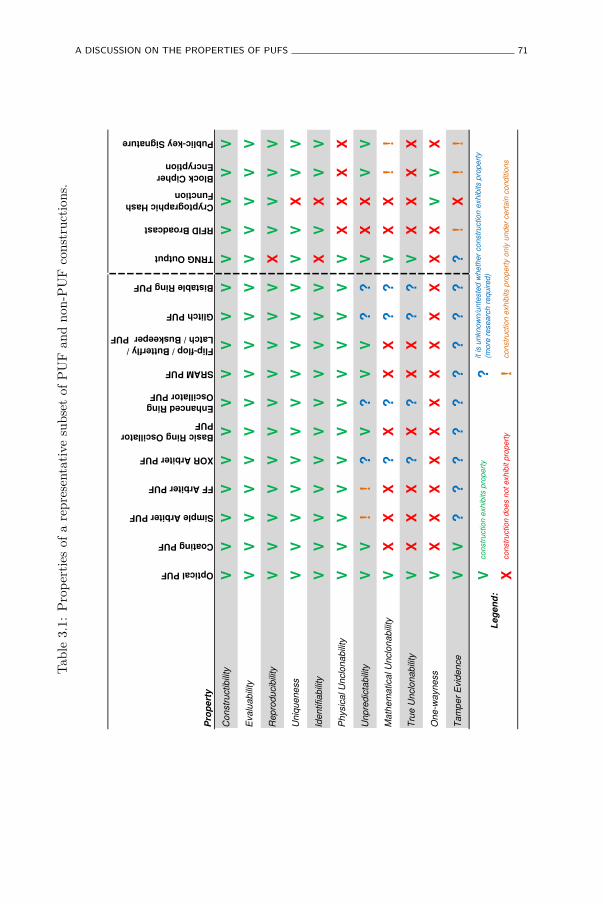
A DISCUSSION ON THE PROPERTIES OF PUFS 71
Tab
le3.
1:P
rop
erti
esof
are
pres
enta
tive
subs
etof
PU
Fan
dno
n-P
UF
cons
truc
tion
s.
Pro
pe
rty
Optical PUF
Coating PUF
Simple Arbiter PUF
FF Arbiter PUF
XOR Arbiter PUF
Basic Ring Oscillator
PUF
Enhanced Ring
Oscillator PUF
SRAM PUF
Flip-flop / Butterfly /
Latch / Buskeeper PUF
Glitch PUF
Bistable Ring PUF
TRNG Output
RFID Broadcast
Cryptographic Hash
Function
Block Cipher
Encryption
Public-key Signature
Con
str
uctib
ility
VV
VV
VV
VV
VV
VV
VV
VV
Eva
lua
bili
tyV
VV
VV
VV
VV
VV
VV
VV
V
Rep
rod
ucib
ility
VV
VV
VV
VV
VV
VX
VV
VV
Un
iqu
en
ess
VV
VV
VV
VV
VV
VV
VX
VV
Ide
ntifia
bili
tyV
VV
VV
VV
VV
VV
XV
XV
V
Ph
ysic
al U
nclo
na
bili
tyV
VV
VV
VV
VV
VV
VX
XX
X
Unp
red
icta
bili
tyV
V!
!?
V?
VV
??
VX
XV
V
Ma
the
ma
tica
l U
nclo
na
bili
tyV
XX
X?
X?
XX
??
VX
X!
!
Tru
e U
nclo
na
bili
tyV
XX
X?
X?
XX
??
VX
XX
X
On
e-w
ayn
ess
VX
XX
XX
XX
XX
XX
XV
VX
Ta
mp
er
Evid
en
ce
VV
??
??
??
??
??
!X
!!
V?
X!
Le
ge
nd
:
co
nstr
uctio
n e
xh
ibits p
rop
ert
y
co
nstr
uctio
n d
oe
s n
ot
exh
ibit p
rope
rty
it is u
nkn
ow
n/u
nte
ste
d w
heth
er
co
nstr
uctio
n e
xh
ibits p
rop
ert
y
(more
re
se
arc
h r
eq
uire
d)
co
nstr
uctio
n e
xh
ibits p
rop
ert
y o
nly
und
er
ce
rta
in c
ond
itio
ns
72 PHYSICALLY UNCLONABLE FUNCTIONS: PROPERTIES
Evaluability. All considered constructions are also evaluable since experimen-tal results are available for all of them. However, some of them require moreevaluation effort than others. The optical PUF evaluation procedure is quiteelaborate, requiring a laser and a very accurate mechanical positioning system.The SRAM PUF and the flip-flop and buskeeper PUFs require a power cycle toevaluate them, since they rely on the power-up behavior of their construction.
Reproducibility. This is the first differentiating property between PUFs andnon-PUFs, since it clearly distinguishes the PUF constructions from theTRNG. A TRNG is by definition not reproducible, since this would make itdeterministic. The other non-PUF reference cases are perfectly reproducible,i.e. with zero intra-distance. The reproducibility of the PUF proposals variesfrom more than 25% average intra-distance for the optical PUF to less than1% for the ring-oscillator PUF.
Uniqueness. All PUF proposals exhibit uniqueness with average inter-distances of merely 23% and 38% for respectively the simple and feed-forwardarbiter PUFs, and very close to 50% for the other constructions. The TRNGevidently also exhibits ideal uniqueness. Uniqueness is a differentiating featurebetween PUFs and hash functions. Because the considered hash function hasno random elements, every implementation instance will exhibit exactly thesame challenge-response behavior. The other three non-PUF constructions areunique if and only if they have been programmed with a unique bit string,which is true with high probability in the regular manufacturing process.
Identifiability. This is the combination of reproducibility and uniqueness.TRNGs and hash functions do not meet this property, respectively fornot being reproducible and not being unique. All other constructionsexhibit identifiability, with for most of them even a large separation betweenthe distributions of intra- and inter-distance, allowing an unambiguousidentification based on their responses.
Physical Unclonability. As expected, physical unclonability is the greatdivider between PUF and non-PUF constructions. The uniqueness of all PUFproposals results from random physical processes during their manufacturingprocess, either implicitly or explicitly, which are so complex that it isconsidered infeasible to have any meaningful influence on them. Moreover,for all considered PUF constructions, these random processes take effect atmicroscopic and (deep) submicron levels, which makes it even more technically
A DISCUSSION ON THE PROPERTIES OF PUFS 73
infeasible to analyse them or exert any control over them. This is in greatcontrast to the uniqueness of the RFID scheme, the block cipher and thesignature algorithm which is based on the programming of a relatively shortrandom bit string. For an adversary which controls the manufacturing process,and hence this programming step, it is not at all difficult to program more thanone instance with the same string. For this reason, these constructions are notconsidered physically unclonable.
Unpredictability. Following the modeling attacks on simple and feed-forwardarbiter PUFs as discussed in Section 2.4.1, these two constructions only remainunpredictable as long as an adversary does not learn enough challenge-responsepairs to accurately train his model. The actual number of unpredictableresponses depends on the details of the implementation and on the state-of-the art in modeling attacks, but this can be very limited: modeling attackshave been presented which achieve a better than random accuracy after lessthan 100 training responses and improve to near perfect accuracy when moreresponses are learned. For the XOR arbiter PUF with a sufficient numberof XOR-ed arbiters (≥ 5), no effective modeling attacks are yet known, andthe same holds for the enhanced ring oscillator PUF, the glitch PUF andthe bistable ring PUF. Although for none of these four PUFs, strong claimsof independence between response bits can be made. For the optical PUF,reasonable arguments are presented by Tuyls et al. [147], Škorić et al. [155]that modeling attacks are computationally infeasible. For the remaining PUFs,response bits are produced by physically distinct elements which is a strongmotivation to assume that different responses are independent and henceinherently unpredictable. Consequently, no modeling attacks are known forthese PUFs. All the non-PUF constructions except for the RFID schemeand the hash function exhibit unpredictability, the TRNG because of randomphysical influences and the block cipher and the signature scheme because ofa secret element and computational complexity arguments. The RFID schemeis trivially predictable since it only has one single fixed response. The hashfunction construction contains no unique element (key) and is easily predicted.
Mathematical Unclonability. Simple and feed-forward arbiter PUF construc-tions are not mathematically unclonable since they are only conditionallyunpredictable. The coating PUF, the ring oscillator PUF, the SRAM PUFand the four other bistable memory element PUFs do not exhibit mathematicalunclonability because the size of their challenge sets is small, which means theycan be fully evaluated to produce a lookup table as a trivial mathematicalclone. For the XOR arbiter PUF, the enhanced ring oscillator PUF, the glitchPUF and the bistable ring PUF, no practical mathematical cloning attacks
74 PHYSICALLY UNCLONABLE FUNCTIONS: PROPERTIES
are known, but more research is required before any strong claims can bemade. Tuyls et al. [147], Škorić et al. [155] argue that the optical PUF isto a large extent mathematically unclonable, since even if (hypothetically) amathematical model of an optical PUF instance could be created, it would becomputationally too complex to be evaluated. However, this turns out to bevery implementation dependent, as Rührmair [117] states that a variant of anoptical PUF with reduced randomness can in fact be modeled. Finally, theblock cipher and the signature algorithm are assumed to be mathematicallyunclonable under the condition that an adversary is not able to extractthe secret key during its unlimited physical access to an instance. Thisimplies that, besides being algorithmically secure, the implementations of thesecryptographic primitives also need to be physically protected, e.g. against side-channel and fault attacks, and against reverse-engineering.
True Unclonability. This is the combination of physical and mathematicalunclonability. The optical PUF is the only one of the considered PUFconstructions for which strong claims of true unclonability can be made.
One-Wayness. Besides the optical PUF, none of the other studied PUFproposals can be considered one-way since they either have a small challengeor a small response set. Pappu [109] presents strong arguments why his opticalPUF construction does exhibit one-wayness, hence being labelled a physicalone-way function. If the block cipher is algorithmically secure and its keyremains secret, it is considered to be hard to invert. The same holds for theunkeyed hash function. A public-key signature algorithm is not guaranteedto be one-way, since everyone with knowledge of the public key can verify thesignature which possibly involves recovering the signed message.
Tamper Evidence. A certain level of tamper evidence was only experimentallydemonstrated for optical PUFs by Pappu [109] and for coating PUFs by Tuylset al. [145]. For all other proposed PUF constructions no results on tamperevidence, neither in the positive nor in the negative sense, are known. Henceno sensible claims on tamper evidence can be made for them. For TRNGs,tamper evidence is not well defined. The remaining non-PUF proposals arenot inherently tamper evident, but can be implemented in a tamper evidentfashion by applying tamper detection measures.
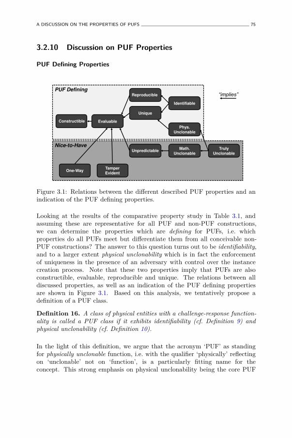
A DISCUSSION ON THE PROPERTIES OF PUFS 75
3.2.10 Discussion on PUF Properties
PUF Defining Properties
³LPSOLHV´
Evaluable
Unique
Identifiable
Phys. Unclonable
Math. Unclonable
Truly Unclonable
One-Way Tamper Evident
PUF Defining
Nice-to-Have
Constructible
Reproducible
Unpredictable
Figure 3.1: Relations between the different described PUF properties and anindication of the PUF defining properties.
Looking at the results of the comparative property study in Table 3.1, andassuming these are representative for all PUF and non-PUF constructions,we can determine the properties which are defining for PUFs, i.e. whichproperties do all PUFs meet but differentiate them from all conceivable non-PUF constructions? The answer to this question turns out to be identifiability,and to a larger extent physical unclonability which is in fact the enforcementof uniqueness in the presence of an adversary with control over the instancecreation process. Note that these two properties imply that PUFs are alsoconstructible, evaluable, reproducible and unique. The relations between alldiscussed properties, as well as an indication of the PUF defining propertiesare shown in Figure 3.1. Based on this analysis, we tentatively propose adefinition of a PUF class.
Definition 16. A class of physical entities with a challenge-response function-ality is called a PUF class if it exhibits identifiability (cf. Definition 9) andphysical unclonability (cf. Definition 10).
In the light of this definition, we argue that the acronym ‘PUF’ as standingfor physically unclonable function, i.e. with the qualifier ‘physically’ reflectingon ‘unclonable’ not on ‘function’, is a particularly fitting name for theconcept. This strong emphasis on physical unclonability being the core PUF
76 PHYSICALLY UNCLONABLE FUNCTIONS: PROPERTIES
property also implicates that if at one point the physical unclonability of aparticular PUF construction is disputed, e.g. due to the natural advancementof manufacturing techniques, it will cease to be a PUF.
Nice-to-Have PUF Properties
Since only identifiability and physical unclonability actually define PUFs, theremaining properties of unpredictability, mathematical and true unclonability,one-wayness and tamper evidence are merely desirable extras, but are notguaranteed for any PUF construction. In fact, there currently seems to beonly one PUF proposal which meets all these properties and that is the opticalPUF as proposed by Pappu [109]. This observation, combined with the factthat it was one of the very first PUF proposals, grants the optical PUF thestatus of prototype PUF. All following PUF constructions aim to achieve asmany of the desirable properties of the optical PUF as possible, but at thesame time aim to provide more integrated implementations.
Since these remaining properties are only nice-to-have qualities, they cannotsimply be assumed to be present in any PUF. This means that PUF designersneed to present strong arguments, preferably of an experimental nature, ifthey claim any of these extra properties for their PUF proposal. (In fact,they also need to show identifiability and physical unclonability to demonstratethat their proposal is a PUF to begin with.) For developers of PUF-basedapplications, this entails that they need to state explicitly if, and to whatextent they rely on any of these nice-to-have properties, since it means thatnot all PUF constructions can be used for their application.
Improving PUF Properties
From Table 3.1 it is clear that mathematical unclonability, and by consequencetrue unclonability, and also one-wayness are hard to come by for most PUFproposals. When these properties are required in a PUF-based application,they can be provided by extending the raw physical PUF instance with analgorithmic primitive exhibiting this property, and enforcing that the resultingPUF-system can only be evaluated with this primitive. This is what was definedas a controlled PUF in Section 2.5.2.
FORMALIZING PUFS 77
3.3 Formalizing PUFs
In Section 3.2, we described meaningful properties of PUFs, and after a broadcomparison identified the ones which define a PUF. Based on this analysis, weproceed towards a strictly formal description of PUFs and their key properties.First, we study earlier proposed attempts at formally describing PUFs andpoint out how they fall short. Next we discuss our approach in setting upthe framework and in Section 3.3.3 we introduce the basic primitives of theframework itself. Using the introduced framework, we respectively proposeformal definitions for the notions of robustness, physical unclonability andunpredictability. The rationale behind the definitions of all concepts andproperties in this section is to provide a meaningful formal model for bothhardware engineers (developing PUFs) and cryptographers (deploying PUFs).
Background. The development of the formal framework for physical functionsand the formal definitions of their properties as described in [8] and inthis section are the shared results of numerous fruitful discussions and anintense research collaboration between the author and professor FrederikArmknecht (Universität Mannheim), professor François-Xavier Standaert(Université catholique de Louvain), Christian Wachsmann and professorAhmad-Reza Sadeghi (both Technische Universität Darmstadt).
3.3.1 Earlier Formalization Attempts
Throughout PUF literature, many authors have attempted to generalize theconcept of a PUF in a more or less formal definition, mainly as a meansto highlight the advantageous properties of a simultaneously proposed newPUF construction. We briefly introduce these definitions and point out whywe believe none of them captures the full spectrum of proposed PUFs andtheir properties, either by being too restrictive, i.e. excluding certain PUFs,or by being too ad hoc, i.e. listing perceived and even assumed properties ofcertain PUFs instead of providing a generalizing model. A similar overviewand discussion has been presented by Rührmair et al. [125]. However, we donot completely follow all their arguments and moreover point out why the newmodels they propose are still insufficient.
Another approach toward defining the functionality of a PUF comes fromthe theoretical corner. Theorists, in an attempt to deploy PUFs in theiralgorithms and protocols, provide rather rigid formal descriptions of PUFs onwhich they can built security reductions. We also discuss these proposals andtheir drawbacks.
78 PHYSICALLY UNCLONABLE FUNCTIONS: PROPERTIES
Physical One-Way Functions
To the best of our knowledge, the first generalizing definition of the PUFconcept is given by Pappu [109], based on the properties of his optical PUFconstruction. He focuses on the one-wayness property of this construction andlabels it a physical one-way function (POWF). The first part of the definition ofa POWF states that it is a deterministic physical interaction that is evaluablein constant time but cannot be inverted by a probabilistic polynomial timeadversary with a non-negligible probability. The second part of the definitionfocusses on the unclonability of the POWF: both simulating a response andphysically cloning the POWF should be hard. The POWF definition is solelybased on the optical PUF, which at that time was the only known PUF. Asother PUFs were introduced shortly after, it became clear that this definitionwas too stringent, in particular regarding the one-wayness assumption. Whilethe optical PUF has very large challenge and response sets, many of the laterintroduced PUFs do not. For these constructions, one-wayness does not holdany longer since inverting such a PUF with non-negligible advantage becomestrivial, as discussed in Section 3.2.7. It is also noteworthy to mention that,as also pointed out by Rührmair et al. [125], for most PUF-based securityapplications, one-wayness is not a required condition. A final issue with thePOWF definition is that it lacks any notion of noise, in fact it even describesa POWF as a deterministic interaction. This is contradicted by the fact thatvirtually all PUF proposals, including the optical PUF, produce noisy responsesdue to uncontrollable physical influences affecting a response evaluation.
Physical Random Functions
With the introduction of delay-based intrinsic PUFs, Gassend et al. [47],propose the definition of a physical random functions to describe PUFs. Inbrief, a physical random function is defined as a function embodied by aphysical device, which is easy to evaluate but hard to predict from a polynomialnumber of challenge-response observations. Note that this definition replacesthe very stringent one-wayness condition from POWFs by a more relaxedunpredictability condition. However, the presentation of modeling attacks onsimple arbiter PUFs by Lee et al. [80] and on more elaborate arbiter PUFs byRührmair et al. [124] demonstrate a significantly reduced unpredictability ofthese types of PUFs. Moreover, the later introduced memory-based intrinsicPUFs only possess at most a polynomial number of challenges and hence do notclassify as physical random functions since they can be easily modeled throughexhaustive readout. Finally, the definition of physical random functions as
FORMALIZING PUFS 79
proposed by Gassend et al. [47] also does not capture the possibility of noisyresponses.
Weak and Strong PUFs
With the introduction of memory-based intrinsic PUFs, Guajardo et al. [50]further refine the formal specification of a PUF. They describe PUFs asinherently unclonable physical systems with a challenge-response behavior. It isassumed that: i) responses to different challenges are independent of each other,ii) it is difficult to come up with responses which have not been observed before,and iii) tampering with a PUF instance substantially changes its challenge-response behavior. For the first time, it is made explicit that PUF responsesare observed as noisy measurements. This definition also comes with a divisionin strong and weak PUFs, depending on how many challenge-response pairsan adversary is allowed to obtain in order to model the PUF. If the numberis exponentially large in some security parameter, the PUF is called a strongPUF, otherwise the PUF is called weak. It can be argued that some of theassumptions made in this description do not have a solid experimental basis,in particular regarding tamper evidence, which has not been tested in practicefor any of the intrinsic PUF proposals. Also, strong PUFs are difficult tocharacterize in general, as the idea of a security parameter is specific to eachPUF instance, and no practical procedure is proposed to exhibit the requiredexponential behavior in practice.
Rührmair et al. [125] build upon the distinction between strong and weak PUFsfrom Guajardo et al. [50] and redefine both notions in terms of a security gamewith an adversary. Weak PUFs are called obfuscating PUFs and are basicallyconsidered as physically obfuscated keys as described in Section 2.5.1. Themain statement in the definition of obfuscating PUFs is that an adversarycannot learn the key after having had access to the PUF for a limited amountof time. Strong PUFs are defined similarly, but here the adversary needs tocome up with the response to a randomly chosen challenge after having hadaccess to the PUF and a PUF oracle for some limited time. Some issues areagain left unresolved in this formalization: first, despite building upon the workof Guajardo et al. [50], responses are not considered to be noisy. Next, the useof a PUF oracle in the definition of a strong PUF seems questionable. It isargued that this oracle is introduced to circumvent practical access restrictionto the PUF. However, if a PUF-based system is secured against any attackspossible by the current state of technology, the access to such an oracle is anunrealistic advantage to the adversary which weakens the proposed definition.
80 PHYSICALLY UNCLONABLE FUNCTIONS: PROPERTIES
PUFs and PUF-PRFs
In [9] we have introduced a first formal PUF model which starts from atheoretical application perspective, rather than from a practical construction-based perspective as most earlier proposals. In [9], we aim to use a PUF as partof a cryptographic algorithm, i.c. a block cipher, and for that goal the previouslydiscussed definitions prove to be insufficient. We explicitly make a distinctionbetween algorithmic and physical properties of a PUF. From the algorithmicside, a PUF is said to be a noisy function for which the distribution of responsesis indistinguishable from a random distribution with a certain amount of min-entropy. From the physical side, a PUF is assumed to be physically unclonableand tamper evident. A PUF-PRF is then defined as a PUF-based systemwith pseudo-random function-like qualities. We already pointed out the lack ofexperimental proof for tamper evidence of intrinsic PUFs in practice, and thesame argument applies to this definition. The description of uniqueness andunpredictability by means of min-entropy provides convenient qualities for thetheoretical application of PUFs, but as it turns out it is hard to give strongproof of min-entropy levels for actual PUF constructions. Contrarily to mostof the previous definitions, PUFs are explicitly defined as noisy functions witha strictly bounded noise magnitude.
PUFs in the Universal Composition Framework
Brzuska et al. [21] continue the theoretical application viewpoint approachtoward defining PUFs, and propose a very formal definition which allowsthem to model PUF functionality in the universal composition frameworkas proposed by Canetti [26]. Like our definition from [9], they define PUFsbased on response distributions having a certain level of min-entropy andalso incorporate a noise threshold. However, the presented formulation isutterly theoretical which makes it unattractive for practice-oriented designersof PUF constructions. Consequentially, there is a significant probability thatan actual PUF construction which lives up to this stringent definition willnever be proposed. Moreover, the strong min-entropy assumptions on the PUFresponses rule out many known PUF constructions and put strong restrictionson others, leading to practical inefficiency.
FORMALIZING PUFS 81
3.3.2 Setup of the Formal Framework
Objective
The basic objective of the formal framework we present in [8] and whichis discussed in detail in the following, is to provide a workable model forboth practice-oriented PUF designers as well as theory-oriented cryptographersdeploying PUFs in algorithms and protocols. Ideally, the model is sufficientlyrealistic, capturing measurable properties of actual PUF proposals, while at thesame time providing sufficient formalism and rigor to allow theoretical securityreductions of systems deploying a PUF as a primitive. Such a frameworkcould serve as an interface between hardware engineers and theoreticalcryptographers, which would be very beneficial for the continued successfuldeployment of PUFs in security systems.
Approach
The approach we take is to start from a minimalistic axiomatic frameworkto describe physical functions and increment it in a flexible manner. First,by hierarchically expanding the notion of a physical function to moreextensive constructions, and secondly by defining modular properties of theseconstructions within the framework.
The particular difficulty experienced by formal modeling attempts of PUFsis dealing with the physical aspect. It is hard to argue about the securityproperties of a physical object because they typically cannot be captured byclassical cryptographic notions such as security parameters or computationallyhard problems. To isolate this difficulty, we capture the physical aspect at thelowest formal level when we axiomatically describe the notion of a physicalfunction. All higher level properties can then be defined using the formalismintroduced to describe physical functions. The particular properties which weconsider are robustness, physical unclonability and unpredictability. Note thatwhat we call a physical function is a very general concept, which is broaderthan only PUFs, and physical unclonability is merely one possible property ofa physical function.
82 PHYSICALLY UNCLONABLE FUNCTIONS: PROPERTIES
3.3.3 Definition and Expansion of a Physical Function
Physical Function (pf)
A physical function pf consists of a physical component p and an evaluationprocedure Evalaev
. A physical component can be physically stimulated, resultingin a measurable effect. The evaluation procedure Evalaev
translates the physicalstimulus and resulting measurement in a digital form, respectively called thechallenge x and the response y of the physical function. The exact challenge-response behavior of a pf is determined by the both the static and dynamicalphysical state of its physical component, and by an evaluation parameter aev
which controls the challenge and response translation, e.g. the quantizationstep size of an analog measurement.
Definition 17. A physical function pf is a probabilistic procedure
pfp,aev: X → Y,
consisting of an evaluation procedure Eval acting upon a physical component p:
y ← pfp,aev(x) = Evalaev
(p; x).
When the physical component and the evaluation parameter are clear from thecontext, we simply write pf instead of pfp,aev
.
Extraction Algorithm (Extract)
A physical function is not a function in the classical sense since, whenchallenged with the same challenge x twice, it may produce different responses.This is an effect of the response representing a measurement of a physicalcomponent whose physical state is partially dynamic, e.g. as a result of non-deterministic random physical noise during the measurement. However, formany applications this is an undesirable feature of a physical function, and itis dealt with by an appropriate extraction algorithm Extractaex
for which it ispossible to guarantee the reproducibility of its output. Many instantiations ofextraction algorithms exist, including the seminal fuzzy extractor as proposedby Dodis et al. [39] [38]. Like for physical functions, we describe extractionalgorithms as generically as possible to allow the greatest possible flexibilityof the framework. An extraction procedure extracts an output z ∈ Z from aresponse y of a pf, and in the process it can also consume and/or produce someadditional side information which we call helper data and denote as w ∈ W.We also introduce an extraction parameter aex which is used to exactly specifyall the deployment details of the extractor.
FORMALIZING PUFS 83
Definition 18. An extraction algorithm Extract is a probabilistic procedure
Extractaex: Y ×W → Z ×W,
which operates in one of two modes depending on the format of the presentedhelper data:
[setup] (z, w)← Extractaex(y, ǫ),
[reconstruction] (z′, w′ = w)← Extractaex(y′, w 6= ǫ),
with ǫ denoting the empty string.
When the extraction parameters are clear from the context, we simply writeExtract instead of Extractaex
.
In setup mode, when no helper data is presented as an input (w = ǫ), theextraction algorithm produces an output z and helper data w. In reconstructionmode, another possibly noisy evaluation of the response y′ is presented togetherwith helper data w which was produced in an earlier setup mode of the extractor.The extraction algorithm re-extracts the output z′ and additionally outputsthe unchanged helper data w. The power of most extraction algorithms isthat, under certain conditions on the pf response distribution, they succeedin recreating exactly the same output in both setup and reconstruction mode:z = z′, given that the helper data generated by the setup mode is used duringreconstruction mode. Besides this reconstruction property, an extractionalgorithm can also provide guarantees about the randomness of its output z.The actual implementation of the extraction algorithm, like is the case for thephysical function, is left up to the practical developer. The generic natureof the definition allows a wide variety of extractor implementations, includingusing no extractor at all by making it the identity function.
Physical Function System (pfs)
In many application scenarios, the use of an extraction algorithm is indis-pensable, and by consequence a user will only be aware of the challengeprovided to the physical function and the output generated by the extractor.The existence of an intermediate physical function response is transparent tohim. Additionally, the relevant security notions in such a scenario will bedetermined by the combination of both the used physical function and thedeployed extraction algorithm. For these reasons, it makes sense to abstractaway the separate notions of a physical function and an extraction algorithm
84 PHYSICALLY UNCLONABLE FUNCTIONS: PROPERTIES
and consider their combination as a single building block. We call such acombination a physical function system pfs.
Definition 19. A physical function system pfs is a probabilistic procedure
pfsp,aev,aex: X ×W → Z ×W,
consisting of the concatenation of a physical function (cf. Definition 17) withan extraction algorithm (cf. Definition 18):
(z, w′)← pfsp,aev,aex(x, w) = Extractaex
(pfp,aev(x), w).
When the physical component and the parameters are clear from the context,we write pfs(x, w) instead of pfsp,aev,aex
(x, w).
We believe that, from a theoretical perspective, it is easier to reason aboutphysical function systems than having to deal with the technical peculiaritiesof physical functions and extractors. Therefore we will define formal propertiesover physical function systems, rather than over physical functions, and weonly refer to the underlying physical functions and extractors when necessary.
Physical Function Infrastructure (F)
The physical component p in a physical function pf is the result of a physicalcreation process Createacr
. The exact manifestation of a created physicalcomponent is determined by stochastic influences during the creation process,and by a controlled deterministic creation parameter acr which defines the fulldetails of the creation process.
Definition 20. For a fixed tuple of parameters (acr, aev, aex), the physicalfunction infrastructure F(acr,aev,aex) refers to the creation process Createacr
andthe set of all physical function systems consisting of the extraction algorithmExtractaex
and a physical function pfp,aevwith a physical component created by
Createacr:
F(acr,aev,aex)△
=(Createacr
,{
pfsp,aev,aex: p← Createacr
}).
Finally, a family of physical function infrastructures is defined as a general-ization of a physical function infrastructure for more than one single creationparameter acr:
F(Acr,aev,aex)△
= {Facr,aev,aex: acr ∈ Acr} .
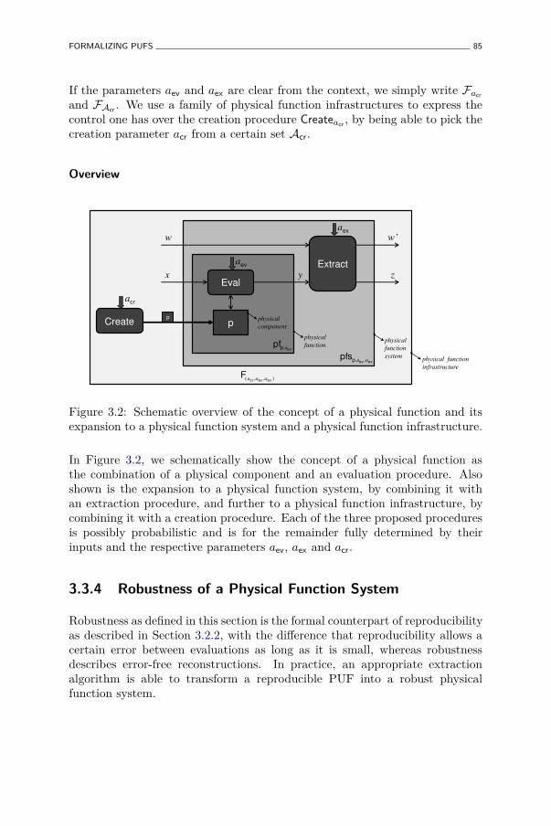
FORMALIZING PUFS 85
If the parameters aev and aex are clear from the context, we simply write Facr
and FAcr. We use a family of physical function infrastructures to express the
control one has over the creation procedure Createacr, by being able to pick the
creation parameter acr from a certain set Acr.
Overview
p
Eval
Extract
Create physical
component
physical
function physical
function
system physical function
infrastructure
x
w Z
z y
p
exevppfs a,a ,
evppf ,a
),,( exevcrF aaa
cra
eva
exa
Figure 3.2: Schematic overview of the concept of a physical function and itsexpansion to a physical function system and a physical function infrastructure.
In Figure 3.2, we schematically show the concept of a physical function asthe combination of a physical component and an evaluation procedure. Alsoshown is the expansion to a physical function system, by combining it withan extraction procedure, and further to a physical function infrastructure, bycombining it with a creation procedure. Each of the three proposed proceduresis possibly probabilistic and is for the remainder fully determined by theirinputs and the respective parameters aev, aex and acr.
3.3.4 Robustness of a Physical Function System
Robustness as defined in this section is the formal counterpart of reproducibilityas described in Section 3.2.2, with the difference that reproducibility allows acertain error between evaluations as long as it is small, whereas robustnessdescribes error-free reconstructions. In practice, an appropriate extractionalgorithm is able to transform a reproducible PUF into a robust physicalfunction system.
86 PHYSICALLY UNCLONABLE FUNCTIONS: PROPERTIES
The robustness of a physical function system is defined as the probability thatan output z produced during setup mode can later be reproduced exactly inreconstruction mode.
Definition 21. The challenge robustness of pfs with respect to x ∈ X is definedas
ρpfs(x)△
= Pr ((z, w)← pfs(x, w) : (z, w)← pfs(x, ǫ)) .
When considering a subset of challenges X ′ ⊆ X , the following relatedrobustness notions can be defined:
• Minimum robustness of pfs with respect to X ′:
ρminpfs (X ′)
△
= minx∈X{ρpfs(x)} .
This is useful when one requires every considered challenge to exhibit aminimal level of robustness.
• Average robustness of pfs with respect to X ′:
ρavpfs(X
′)△
=∑
x∈X
ρpfs(x) · Pr (x← X ′) .
From a practical viewpoint it is often sufficient to have a high enoughaverage robustness.
This notion of robustness can even be extended further to physical functionsinfrastructures. The average robustness of a physical function infrastructure Fis defined as:
ρavF (X ′)
△
=∑
pfs∈F
ρavF (X ′) · Pr (F ← Create) .
When X ′ = X or when the content of X ′ is clear from the context, we simplywrite ρmin
pfs , ρavpfs and ρav
F .
3.3.5 Physical Unclonability of a Physical Function System
Defining a (Physical) Clone
Before we define unclonability, we first need to agree on what we consider tobe a clone. Intuitively, we consider two instances clones if they show ‘similar
FORMALIZING PUFS 87
behavior.’ However, there are a number of technical details which have to betaken into account in order to turn this intuition into a formal definition.
First of all, we need to make explicit that we consider physical unclonability,and therefore also only physical clones. Given the definition of a physicalfunction system, there are a number of non-physical ways one can think ofto create ‘similar instances.’ For example, a physical function system deployingan extraction algorithm which outputs a fixed constant is trivial to clone, butit is obvious that we do not consider this a physical clone. A similar argumentholds for the evaluation procedure of the physical function, e.g. imagine anevaluation procedure which quantizes a physical measurement into a zero bitresponse, which is basically a fixed value. We explicitly only consider physicalclones by stating that two physical functions systems which are consideredclones can only differ in their physical component p, while their evaluation andextraction procedures and parameters need to be identical.
Secondly, there are many levels of ‘similarity’: two physical function systemscan be ‘less different as expected’ or they can be truly ‘indistinguishable’. Thisneeds to be captured by a quantitative parameter. Also, we need to considersimilarity with respect to a subset of challenges. If two physical functionsystems happen to coincide on a subset of challenges which is critical for aparticular application, they need to be considered clones, even if they showcompletely different behavior on the remainder of challenges.
Finally, when attempting to formalize the notion of ‘similarity’ for physicalfunction systems, we will run into robustness again. How does one definesimilarity with respect to a physical function system which even by itself doesnot always generate similar outputs? To tackle this issue, we are guided by twointuitive arguments: i) every physical function system pfs should be a clone ofitself (except for not deploying a different physical component), and ii) a cloneof a physical function system pfs cannot be more similar to pfs than pfs is toitself, as expressed by its robustness. In other words, the robustness of pfs isa natural upper bound for how similar a clone can be to pfs. Therefore, weexpress the similarity of a clone to pfs relative to its robustness.
Definition 22. For a fixed tuple of parameters (aev, aex), let pfs(= pfsp,aev,aex)
and pfs′(= pfsp′,aev,aex) be two physical function systems which are identical
except for their physical components, p 6= p′. We say pfs is a δ-clone of pfs′
with respect to X ′ ⊆ X , if ∀x ∈ X ′ it holds that
Pr((z, w)← pfs′(x, w) : (z, w)← pfs(x, ǫ)
)≥ δ · ρpfs(x),
with 0 ≤ δ ≤ 1. In short-hand notation, we write: pfsδ;X ′
≡ pfs′.
88 PHYSICALLY UNCLONABLE FUNCTIONS: PROPERTIES
By p 6= p′ we mean that p and p′ are distinct physical entities, i.e. occupyingdifferent positions in space-time, but they are allowed to be physically similarto any level of precision. Note that, except for not deploying different physicalcomponents, every physical function system is a (δ = 1,X ′ = X )-clone of itself.
Defining Physical Unclonability
Now that we have a formal definition of a clone, we can define physicalunclonability by formalizing the statement: ‘it is difficult to produce a clone.’However, again some technicalities need to be considered before a formaldescription can be presented.
We first need to specify the capabilities of the adversary A who is trying toproduce a clone. In practice, such an adversary will have access to a numberof executions of the creation procedure of physical components. Possibly,he even has an amount of control over it, i.e. he can influence the physicalprocesses taking place during creation within certain boundaries. We capturethis formally by allowing the adversary to select the creation parameter acr froma particular subset Acr. We use the notion of a family of physical functioninfrastructures FAcr
to describe this. The adversarial model is described bymeans of a security game between the adversary and a creation oracle.
We also need to distinguish between two variants of unclonability:
• Existential unclonability means that it is hard to create a pair of physicalfunction systems such that one is a clone of the other.
• Selective unclonability means that given a particular physical functionsystem, it is hard to create a second one which is a clone of the first one.
Note that in general, existential unclonability implies selective unclonabilityand is therefore a stronger security notion. We will give a formal definitionfor existential unclonability, but the same approach as presented here can beapplied to describe selective unclonability.
To formally define (existential) unclonability (or cloning resistance), we firstdescribe the adversary model A by means of a cloning game Gameclone
A (Acr, q):
• In the cloning game GamecloneA (Acr, q), an adversary is allowed to make
up to q queries to a creation oracle OCreateAcr
, with q ≥ 2.
• The creation oracle OCreateAcr
expects a creation parameter acr as queryinput. If acr ∈ Acr, then the oracle invokes the physical component
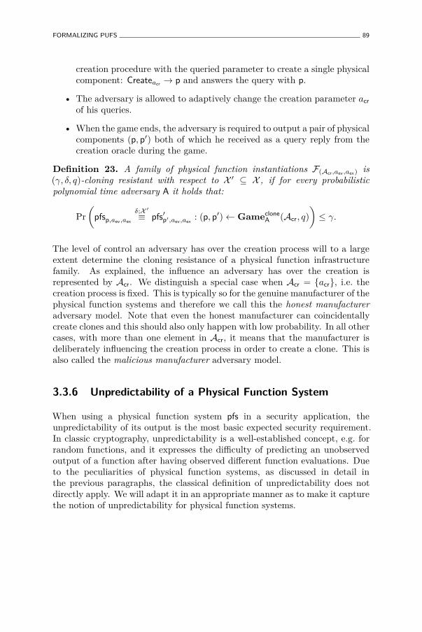
FORMALIZING PUFS 89
creation procedure with the queried parameter to create a single physicalcomponent: Createacr
→ p and answers the query with p.
• The adversary is allowed to adaptively change the creation parameter acr
of his queries.
• When the game ends, the adversary is required to output a pair of physicalcomponents (p, p′) both of which he received as a query reply from thecreation oracle during the game.
Definition 23. A family of physical function instantiations F(Acr,aev,aex) is(γ, δ, q)-cloning resistant with respect to X ′ ⊆ X , if for every probabilisticpolynomial time adversary A it holds that:
Pr
(pfsp,aev,aex
δ;X ′
≡ pfs′p′,aev,aex: (p, p′)← Gameclone
A (Acr, q)
)≤ γ.
The level of control an adversary has over the creation process will to a largeextent determine the cloning resistance of a physical function infrastructurefamily. As explained, the influence an adversary has over the creation isrepresented by Acr. We distinguish a special case when Acr = {acr}, i.e. thecreation process is fixed. This is typically so for the genuine manufacturer of thephysical function systems and therefore we call this the honest manufactureradversary model. Note that even the honest manufacturer can coincidentallycreate clones and this should also only happen with low probability. In all othercases, with more than one element in Acr, it means that the manufacturer isdeliberately influencing the creation process in order to create a clone. This isalso called the malicious manufacturer adversary model.
3.3.6 Unpredictability of a Physical Function System
When using a physical function system pfs in a security application, theunpredictability of its output is the most basic expected security requirement.In classic cryptography, unpredictability is a well-established concept, e.g. forrandom functions, and it expresses the difficulty of predicting an unobservedoutput of a function after having observed different function evaluations. Dueto the peculiarities of physical function systems, as discussed in detail inthe previous paragraphs, the classical definition of unpredictability does notdirectly apply. We will adapt it in an appropriate manner as to make it capturethe notion of unpredictability for physical function systems.
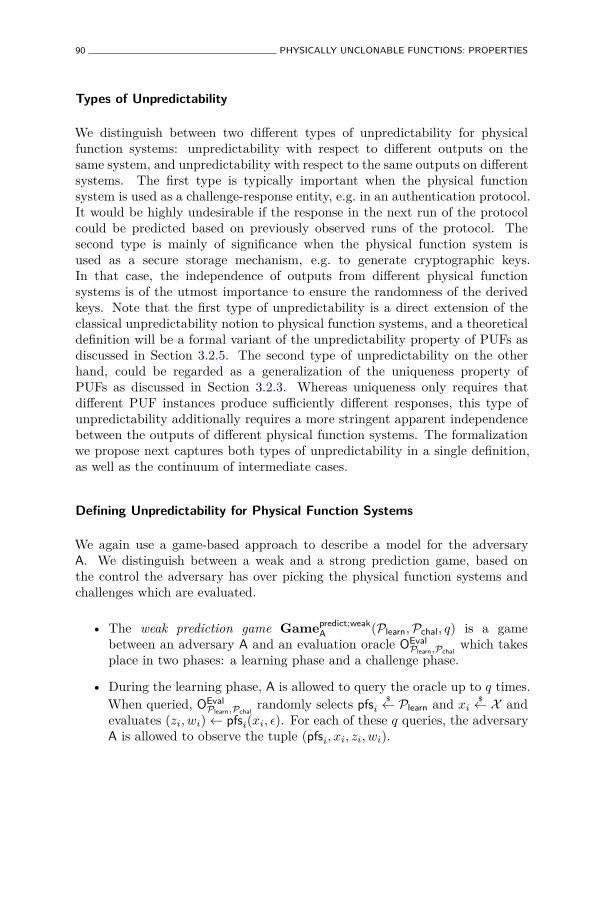
90 PHYSICALLY UNCLONABLE FUNCTIONS: PROPERTIES
Types of Unpredictability
We distinguish between two different types of unpredictability for physicalfunction systems: unpredictability with respect to different outputs on thesame system, and unpredictability with respect to the same outputs on differentsystems. The first type is typically important when the physical functionsystem is used as a challenge-response entity, e.g. in an authentication protocol.It would be highly undesirable if the response in the next run of the protocolcould be predicted based on previously observed runs of the protocol. Thesecond type is mainly of significance when the physical function system isused as a secure storage mechanism, e.g. to generate cryptographic keys.In that case, the independence of outputs from different physical functionsystems is of the utmost importance to ensure the randomness of the derivedkeys. Note that the first type of unpredictability is a direct extension of theclassical unpredictability notion to physical function systems, and a theoreticaldefinition will be a formal variant of the unpredictability property of PUFs asdiscussed in Section 3.2.5. The second type of unpredictability on the otherhand, could be regarded as a generalization of the uniqueness property ofPUFs as discussed in Section 3.2.3. Whereas uniqueness only requires thatdifferent PUF instances produce sufficiently different responses, this type ofunpredictability additionally requires a more stringent apparent independencebetween the outputs of different physical function systems. The formalizationwe propose next captures both types of unpredictability in a single definition,as well as the continuum of intermediate cases.
Defining Unpredictability for Physical Function Systems
We again use a game-based approach to describe a model for the adversaryA. We distinguish between a weak and a strong prediction game, based onthe control the adversary has over picking the physical function systems andchallenges which are evaluated.
• The weak prediction game Gamepredict;weakA (Plearn,Pchal, q) is a game
between an adversary A and an evaluation oracle OEvalPlearn,Pchal
which takesplace in two phases: a learning phase and a challenge phase.
• During the learning phase, A is allowed to query the oracle up to q times.When queried, OEval
Plearn,Pchalrandomly selects pfsi
$← Plearn and xi
$← X and
evaluates (zi, wi)← pfsi(xi, ǫ). For each of these q queries, the adversaryA is allowed to observe the tuple (pfsi, xi, zi, wi).
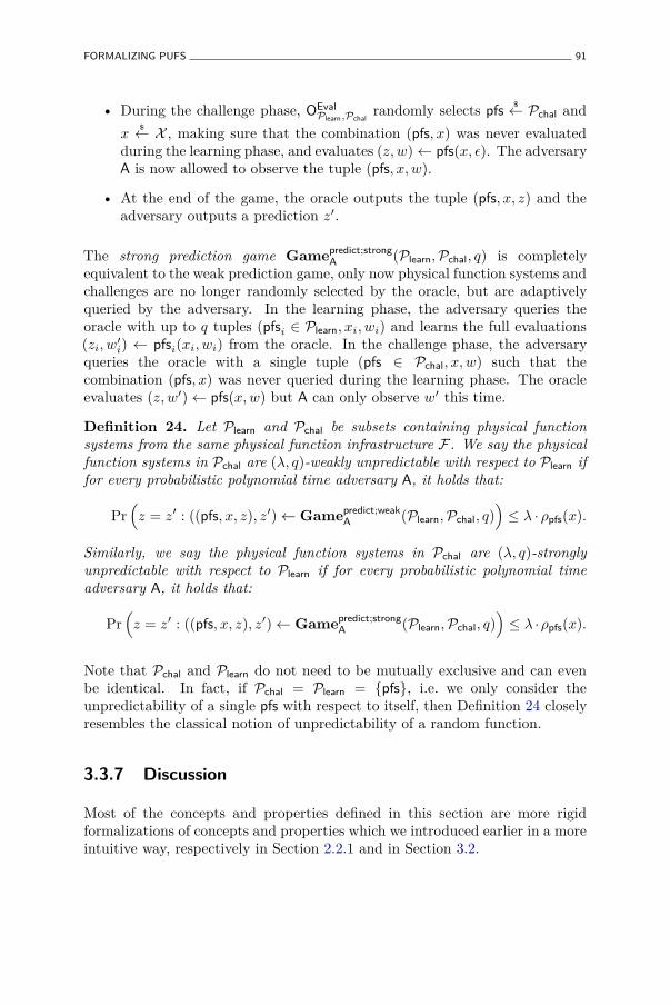
FORMALIZING PUFS 91
• During the challenge phase, OEvalPlearn,Pchal
randomly selects pfs$← Pchal and
x$← X , making sure that the combination (pfs, x) was never evaluated
during the learning phase, and evaluates (z, w)← pfs(x, ǫ). The adversaryA is now allowed to observe the tuple (pfs, x, w).
• At the end of the game, the oracle outputs the tuple (pfs, x, z) and theadversary outputs a prediction z′.
The strong prediction game Gamepredict;strongA (Plearn,Pchal, q) is completely
equivalent to the weak prediction game, only now physical function systems andchallenges are no longer randomly selected by the oracle, but are adaptivelyqueried by the adversary. In the learning phase, the adversary queries theoracle with up to q tuples (pfsi ∈ Plearn, xi, wi) and learns the full evaluations(zi, w′i) ← pfsi(xi, wi) from the oracle. In the challenge phase, the adversaryqueries the oracle with a single tuple (pfs ∈ Pchal, x, w) such that thecombination (pfs, x) was never queried during the learning phase. The oracleevaluates (z, w′)← pfs(x, w) but A can only observe w′ this time.
Definition 24. Let Plearn and Pchal be subsets containing physical functionsystems from the same physical function infrastructure F . We say the physicalfunction systems in Pchal are (λ, q)-weakly unpredictable with respect to Plearn iffor every probabilistic polynomial time adversary A, it holds that:
Pr(
z = z′ : ((pfs, x, z), z′)← Gamepredict;weakA (Plearn,Pchal, q)
)≤ λ · ρpfs(x).
Similarly, we say the physical function systems in Pchal are (λ, q)-stronglyunpredictable with respect to Plearn if for every probabilistic polynomial timeadversary A, it holds that:
Pr(
z = z′ : ((pfs, x, z), z′)← Gamepredict;strongA (Plearn,Pchal, q)
)≤ λ ·ρpfs(x).
Note that Pchal and Plearn do not need to be mutually exclusive and can evenbe identical. In fact, if Pchal = Plearn = {pfs}, i.e. we only consider theunpredictability of a single pfs with respect to itself, then Definition 24 closelyresembles the classical notion of unpredictability of a random function.
3.3.7 Discussion
Most of the concepts and properties defined in this section are more rigidformalizations of concepts and properties which we introduced earlier in a moreintuitive way, respectively in Section 2.2.1 and in Section 3.2.
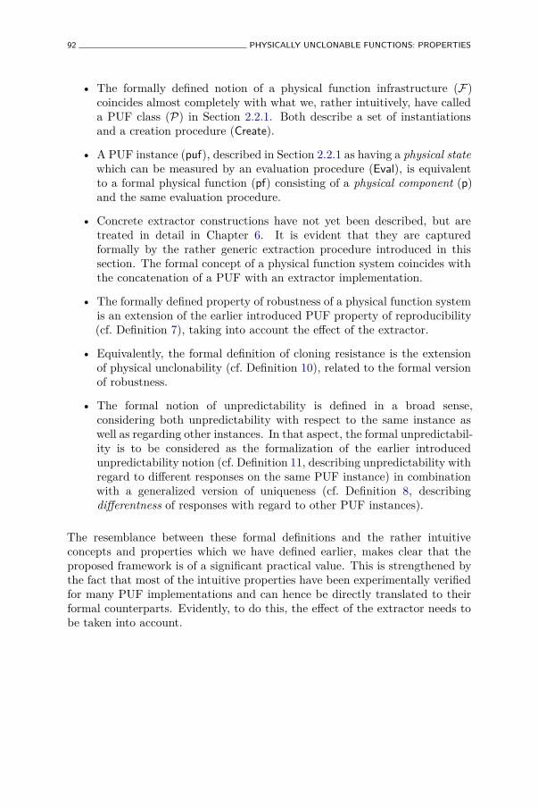
92 PHYSICALLY UNCLONABLE FUNCTIONS: PROPERTIES
• The formally defined notion of a physical function infrastructure (F)coincides almost completely with what we, rather intuitively, have calleda PUF class (P) in Section 2.2.1. Both describe a set of instantiationsand a creation procedure (Create).
• A PUF instance (puf), described in Section 2.2.1 as having a physical statewhich can be measured by an evaluation procedure (Eval), is equivalentto a formal physical function (pf) consisting of a physical component (p)and the same evaluation procedure.
• Concrete extractor constructions have not yet been described, but aretreated in detail in Chapter 6. It is evident that they are capturedformally by the rather generic extraction procedure introduced in thissection. The formal concept of a physical function system coincides withthe concatenation of a PUF with an extractor implementation.
• The formally defined property of robustness of a physical function systemis an extension of the earlier introduced PUF property of reproducibility(cf. Definition 7), taking into account the effect of the extractor.
• Equivalently, the formal definition of cloning resistance is the extensionof physical unclonability (cf. Definition 10), related to the formal versionof robustness.
• The formal notion of unpredictability is defined in a broad sense,considering both unpredictability with respect to the same instance aswell as regarding other instances. In that aspect, the formal unpredictabil-ity is to be considered as the formalization of the earlier introducedunpredictability notion (cf. Definition 11, describing unpredictability withregard to different responses on the same PUF instance) in combinationwith a generalized version of uniqueness (cf. Definition 8, describingdifferentness of responses with regard to other PUF instances).
The resemblance between these formal definitions and the rather intuitiveconcepts and properties which we have defined earlier, makes clear that theproposed framework is of a significant practical value. This is strengthened bythe fact that most of the intuitive properties have been experimentally verifiedfor many PUF implementations and can hence be directly translated to theirformal counterparts. Evidently, to do this, the effect of the extractor needs tobe taken into account.
CONCLUSION 93
3.4 Conclusion
Following an extensive study of eleven meaningful PUF properties on arepresentative subset of PUF constructions, and on a reference set of non-PUF constructions, we are able to extract the defining properties of aPUF: identifiability and physical unclonability, and by implicationconstructibility, evaluability, reproducibility and uniqueness. The remainingproperties of unpredictability, mathematical and true unclonability, one-wayness and tamper evidence are classified as nice-to-have, but are not strictlyrequired for a construction to be called a PUF. This also means that manyPUF proposals in fact do not exhibit these nice-to-have properties, or at thevery best it remains as yet unclear whether they do. In this light, the opticalPUF as proposed by Pappu et al. [110] serves as an exemplary prototype PUF,meeting all mentioned properties to a major extent. Most intrinsic PUFs fallshort on the property of mathematical unclonability, and the existence of astrong intrinsic PUF with motivated and verified security guarantees remainsan open question. One-wayness turns out to be a particularly unfitting propertyfor intrinsic PUFs, which is partially caused by the ambiguity of consideringthe one-wayness of PUFs. Tamper evidence, while often proclaimed as one ofthe major advantages of using PUFs, remains a question mark for all intrinsicPUF proposals, as no experimental results on any construction are known.
Based on these results and with the aim of formalizing these particularlyinteresting properties, we introduce a framework for working with PUFs (andphysical function in general) in a theoretical security setting. Using theintroduced primitives in this framework, we formally define robustness, physicalunclonability and unpredictability of a physical function.

Chapter 4
Implementation andExperimental Analysis ofIntrinsic PUFs
Performing an experiment amounts to asking theUniverse a question.
John Walker
4.1 Introduction
4.1.1 Motivation
All currently known intrinsic PUF implementations are silicon-based and obtaintheir PUF behavior from process variations during the manufacturing of siliconchips. These PUFs are of particular interest, because their response valuescan be used as a secret element in a larger security implementation on thesame silicon chip. Deploying an intrinsic PUF in a security application in thisway provides interesting practical and security advantages. We will discussapplications of intrinsic PUFs and their added value in great detail, respectivelyfor PUF-based authentication in Chapter 5 and PUF-based key generation inChapter 6.
95
96 IMPLEMENTATION AND EXPERIMENTAL ANALYSIS OF INTRINSIC PUFS
The realization that a silicon intrinsic PUF can serve as an integral hardwaresecurity primitive with valuable properties such as uniqueness and unpre-dictability, and in particular physical unclonability which cannot be obtainedsolely from algorithmic constructions, has led to a great interest into theirconstruction. Many intrinsic PUF implementations were proposed over timeand are discussed in detail in Section 2.4. When one actually wants to deployan intrinsic PUF in a hardware security system, interest goes out to the levelsof efficiency and performance of all these different constructions, both from aPUF perspective (which construction shows the best PUF behavior) as wellas from a typical hardware design perspective (which construction offers thelowest area, highest speed, lowest power use, etc.). Section 2.4.8 provides anoverview of known experimental results concerning PUF behavior, but it isalso made clear that a comparison of different proposals solely based on theseresults is not entirely objective. This for a number of reasons:
1. For all known intrinsic PUF constructions, as for nearly all hardwaresecurity primitives, there exists a trade-off between area/speed andsecurity, i.e. larger and/or slower implementations typically offer higherlevels of security. In the overview in Section 2.4.8, which listsexperimental PUF results available in literature, some of the consideredimplementations are heavily biased towards optimizing their PUFbehavior by greatly sacrificing on implementation area and/or speed,while others are not.
2. Experimental PUF results always focus on two properties, reliability anduniqueness, which are mostly summarized by calculating the averageresponse intra-distance (µintra
P ) and inter-distance (µinter
P ) of the experiment.Good PUF behavior is expressed by a small µintra
P and a large µinter
P .However, it is not immediately clear how to combine both measures intoa single quality parameter for a particular PUF construction.
3. The results presented in Section 2.4.8 come from implementations in avariety of different technologies and platforms. It is typically hard toaccurately scale implementation results such as area and speed from onetechnology to another, e.g. between different CMOS technology nodes,and scaling between different platforms, e.g. from FPGA to ASIC, canonly be done very roughly. Extrapolation of PUF behavior results todifferent technologies and platforms is virtually impossible.
The first two issues cannot be dealt with for bare PUFs, but need to beconsidered in the application context of the bigger system deploying thePUF. The optimal trade-off between security and efficiency, as well as therelation between reliability and uniqueness, are determined by the requirements
INTRODUCTION 97
and constraints of the security system as a whole. Optimizing the PUFimplementation is an entangled part of a bigger design optimization processwhich will be discussed in detail for PUF-based authentication systems inChapter 5 and for PUF-based cryptographic key generation in Chapter 6.
The last issue can be approached by implementing different intrinsic PUFproposals on the same platform and in the same technology. This will be themain topic of this chapter. A selection is made of intrinsic PUF proposals whichwere proven to show acceptable PUF behavior, and a number of instantiationsof each of them is integrated in an ASIC design. This ASIC design is processedand a significant set of silicon chips implementing this design is manufactured.Based on this set of devices, valuable experimental PUF data is gatheredwhich can be cross-compared without restraint, since it results from PUFconstructions implemented on the same silicon die.
Background. Designing and manufacturing an ASIC is a complex, time-consuming, and costly undertaking with significant risk of failure. The findingspresented in this chapter are the joint successful result of a larger Europeanresearch project called ‘UNIQUE’ in which our institution was a partner [6].We definitely want to acknowledge the other project partners which contributedheavily to the design, production and evaluation of the test chip discussed inthis chapter. The main contributions of the author and its institution are in thepreparation and setup of the ASIC development, the development and design ofthe ring oscillator PUF, the arbiter PUF and the latch PUF implementations,the monitoring of the back-end ASIC manufacturing process, the developmentof interfacing methods for the ASIC, and the analysis and interpretation of themeasurement results.
4.1.2 Chapter Goals
The main goal of this chapter is to produce a practical and an objective analysisand comparison of different intrinsic PUF constructions, by implementing themon the same platform, evaluating them under the same conditions, and assessingthem on the same characteristics. In more detail, in this chapter we plan to:
• Discuss the design process and implementation details of a custom testchip carrying instantiations of six different intrinsic PUFs.
• Present an in-depth analysis of the uniqueness and reproducibility ofthe evaluation results of the test chip implementations, including theinfluence of varying evaluation conditions. This analysis should result

98 IMPLEMENTATION AND EXPERIMENTAL ANALYSIS OF INTRINSIC PUFS
in a practically usable characterization of these properties for everyPUF instance, which can be immediately plugged in to the design andoptimization process of an application seeking to deploy one of these PUFimplementations.
• Discuss the notion of PUF response entropy and introduce a number ofpractical entropy bounds which can be computed based on experimentallyobtained response evaluations, including a method to calculate a PUFresponse entropy bound based on the results of a modeling attack.
4.1.3 Chapter Overview
Section 4.2 discusses the realization of the intrinsic PUF test chip, fromits initial design rationale and requirements, over its architecture and thedescription of its building blocks, up to its manufacturing flow details. InSection 4.3, we describe how the test chip samples were evaluated and wepresent a complete analysis of the uniqueness and reproducibility based on alarge data set of evaluation results. The entropy of a PUF response is describedin Section 4.4 as a measure for its unpredictability. We introduce a numberof increasingly tighter bounds on the response entropy of a PUF, based onconsidering increasingly more advanced adversary models. Finally the mainresults of this chapter are summarized in Section 4.5.
4.2 Test Chip Design
4.2.1 Design Rationale
The rationale behind the design of the test chip is guided by two mainconsiderations:
i. In the end, the goal of the test chip is to collect statistically significantexperimental data from intrinsic PUF implementations. Ideally, we would liketo implement as many and as large instances as possible from as many differentintrinsic PUF proposals as possible and evaluate them in a quick, easy andrealistic manner, taking into account that the available area budget should bemore or less evenly distributed among the different PUFs.
ii. Designing and producing an ASIC is a very complex process with a minimalmargin for error. The probability of critical failures increases steadily with thesize and complexity of the design. Since the coordinating project provides only
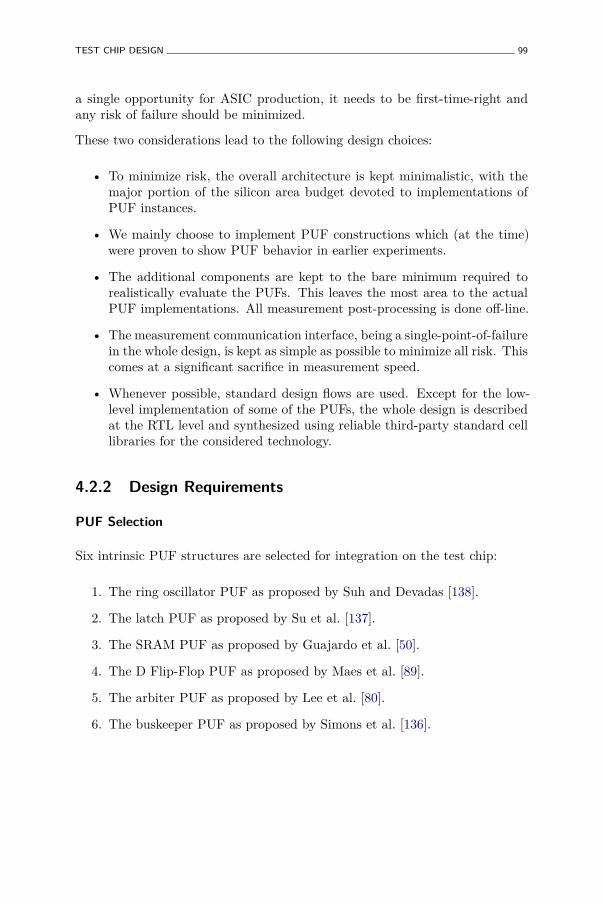
TEST CHIP DESIGN 99
a single opportunity for ASIC production, it needs to be first-time-right andany risk of failure should be minimized.
These two considerations lead to the following design choices:
• To minimize risk, the overall architecture is kept minimalistic, with themajor portion of the silicon area budget devoted to implementations ofPUF instances.
• We mainly choose to implement PUF constructions which (at the time)were proven to show PUF behavior in earlier experiments.
• The additional components are kept to the bare minimum required torealistically evaluate the PUFs. This leaves the most area to the actualPUF implementations. All measurement post-processing is done off-line.
• The measurement communication interface, being a single-point-of-failurein the whole design, is kept as simple as possible to minimize all risk. Thiscomes at a significant sacrifice in measurement speed.
• Whenever possible, standard design flows are used. Except for the low-level implementation of some of the PUFs, the whole design is describedat the RTL level and synthesized using reliable third-party standard celllibraries for the considered technology.
4.2.2 Design Requirements
PUF Selection
Six intrinsic PUF structures are selected for integration on the test chip:
1. The ring oscillator PUF as proposed by Suh and Devadas [138].
2. The latch PUF as proposed by Su et al. [137].
3. The SRAM PUF as proposed by Guajardo et al. [50].
4. The D Flip-Flop PUF as proposed by Maes et al. [89].
5. The arbiter PUF as proposed by Lee et al. [80].
6. The buskeeper PUF as proposed by Simons et al. [136].
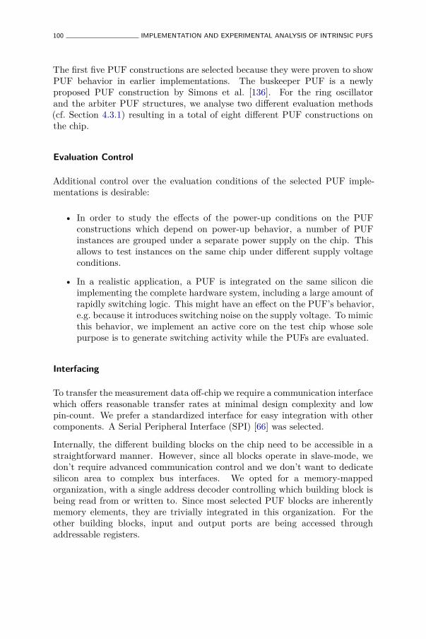
100 IMPLEMENTATION AND EXPERIMENTAL ANALYSIS OF INTRINSIC PUFS
The first five PUF constructions are selected because they were proven to showPUF behavior in earlier implementations. The buskeeper PUF is a newlyproposed PUF construction by Simons et al. [136]. For the ring oscillatorand the arbiter PUF structures, we analyse two different evaluation methods(cf. Section 4.3.1) resulting in a total of eight different PUF constructions onthe chip.
Evaluation Control
Additional control over the evaluation conditions of the selected PUF imple-mentations is desirable:
• In order to study the effects of the power-up conditions on the PUFconstructions which depend on power-up behavior, a number of PUFinstances are grouped under a separate power supply on the chip. Thisallows to test instances on the same chip under different supply voltageconditions.
• In a realistic application, a PUF is integrated on the same silicon dieimplementing the complete hardware system, including a large amount ofrapidly switching logic. This might have an effect on the PUF’s behavior,e.g. because it introduces switching noise on the supply voltage. To mimicthis behavior, we implement an active core on the test chip whose solepurpose is to generate switching activity while the PUFs are evaluated.
Interfacing
To transfer the measurement data off-chip we require a communication interfacewhich offers reasonable transfer rates at minimal design complexity and lowpin-count. We prefer a standardized interface for easy integration with othercomponents. A Serial Peripheral Interface (SPI) [66] was selected.
Internally, the different building blocks on the chip need to be accessible in astraightforward manner. However, since all blocks operate in slave-mode, wedon’t require advanced communication control and we don’t want to dedicatesilicon area to complex bus interfaces. We opted for a memory-mappedorganization, with a single address decoder controlling which building block isbeing read from or written to. Since most selected PUF blocks are inherentlymemory elements, they are trivially integrated in this organization. For theother building blocks, input and output ports are being accessed throughaddressable registers.
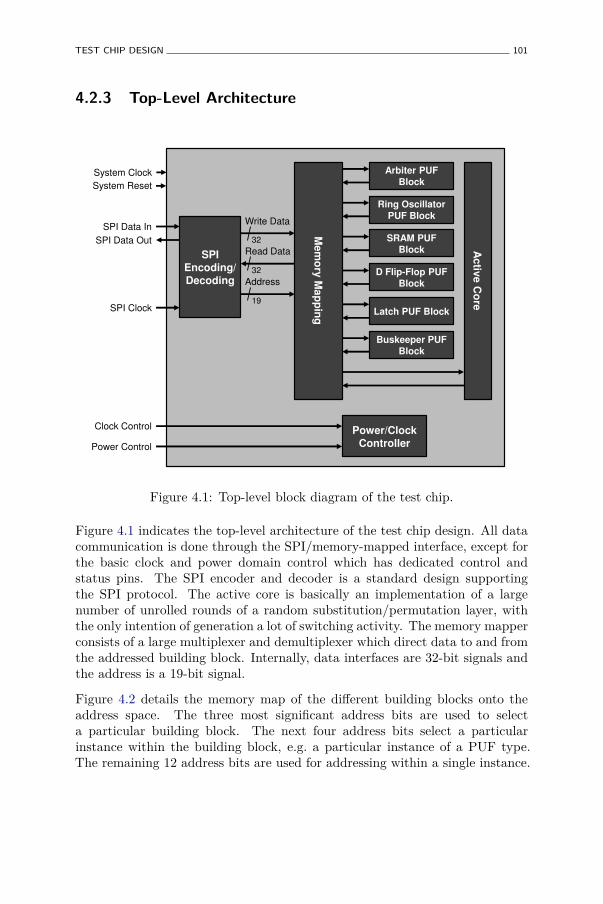
TEST CHIP DESIGN 101
4.2.3 Top-Level Architecture
Arbiter PUF
Block
Ring Oscillator
PUF Block
SRAM PUF
Block
D Flip-Flop PUF
Block
Latch PUF Block
Buskeeper PUF
Block
Ac
tive
Co
re
SPI Encoding/ Decoding
Me
mo
ry M
ap
pin
g
Power/Clock Controller
SPI Data In
SPI Data Out
Clock Control
Power Control
Write Data
Read Data
Address
SPI Clock
System Reset
32
32
19
System Clock
Figure 4.1: Top-level block diagram of the test chip.
Figure 4.1 indicates the top-level architecture of the test chip design. All datacommunication is done through the SPI/memory-mapped interface, except forthe basic clock and power domain control which has dedicated control andstatus pins. The SPI encoder and decoder is a standard design supportingthe SPI protocol. The active core is basically an implementation of a largenumber of unrolled rounds of a random substitution/permutation layer, withthe only intention of generation a lot of switching activity. The memory mapperconsists of a large multiplexer and demultiplexer which direct data to and fromthe addressed building block. Internally, data interfaces are 32-bit signals andthe address is a 19-bit signal.
Figure 4.2 details the memory map of the different building blocks onto theaddress space. The three most significant address bits are used to selecta particular building block. The next four address bits select a particularinstance within the building block, e.g. a particular instance of a PUF type.The remaining 12 address bits are used for addressing within a single instance.
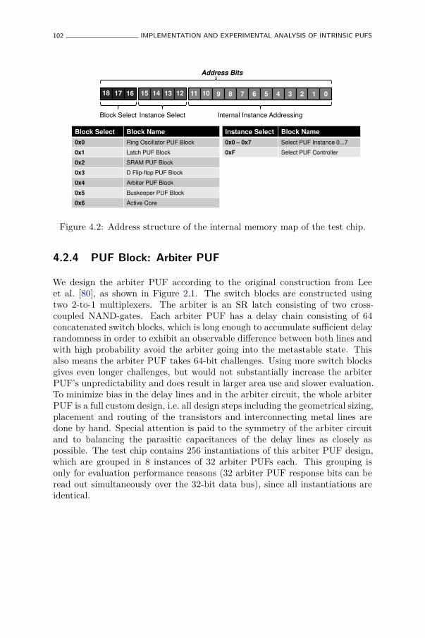
102 IMPLEMENTATION AND EXPERIMENTAL ANALYSIS OF INTRINSIC PUFS
9 8 7 6 5 4 3 2 1 0
Block Select Instance Select Internal Instance Addressing
Address Bits
Block Select Block Name
0x0 Ring Oscillator PUF Block
0x1 Latch PUF Block
0x2 SRAM PUF Block
0x3 D Flip-flop PUF Block
0x4 Arbiter PUF Block
0x5 Buskeeper PUF Block
0x6 Active Core
Instance Select Block Name
0x0 ± 0x7 Select PUF Instance 0...7
0xF Select PUF Controller
18 17 16 15 14 13 12 11 10
Figure 4.2: Address structure of the internal memory map of the test chip.
4.2.4 PUF Block: Arbiter PUF
We design the arbiter PUF according to the original construction from Leeet al. [80], as shown in Figure 2.1. The switch blocks are constructed usingtwo 2-to-1 multiplexers. The arbiter is an SR latch consisting of two cross-coupled NAND-gates. Each arbiter PUF has a delay chain consisting of 64concatenated switch blocks, which is long enough to accumulate sufficient delayrandomness in order to exhibit an observable difference between both lines andwith high probability avoid the arbiter going into the metastable state. Thisalso means the arbiter PUF takes 64-bit challenges. Using more switch blocksgives even longer challenges, but would not substantially increase the arbiterPUF’s unpredictability and does result in larger area use and slower evaluation.To minimize bias in the delay lines and in the arbiter circuit, the whole arbiterPUF is a full custom design, i.e. all design steps including the geometrical sizing,placement and routing of the transistors and interconnecting metal lines aredone by hand. Special attention is paid to the symmetry of the arbiter circuitand to balancing the parasitic capacitances of the delay lines as closely aspossible. The test chip contains 256 instantiations of this arbiter PUF design,which are grouped in 8 instances of 32 arbiter PUFs each. This grouping isonly for evaluation performance reasons (32 arbiter PUF response bits can beread out simultaneously over the 32-bit data bus), since all instantiations areidentical.
TEST CHIP DESIGN 103
4.2.5 PUF Block: Ring Oscillator PUF
The design of the ring oscillator PUF is based on the construction from Suh andDevadas [138] which is depicted in Figure 2.3. A ring oscillator consists of 80chained inverters and one NAND gate to control the oscillation. The number oflooped inverters roughly determines the nominal frequency of the ring oscillator,and in the order of 60-80 inverters is required to obtain frequencies in therange of 500 − 700MHz which are countable with regular digital countersin the targeted technology. Of this ring oscillator, 4096 identical copies areimplemented on the test chip, arranged in 16 batches of 256 oscillators each.Every batch has a single frequency counter and a 256-to-1 multiplexer connectsone of the batch’s oscillators to the counter. To cope with the high frequencyoscillations, the counter is implemented as a 32-bit toggle counter which has avery short critical path. Since there are 16 batches, each with its own counter,16 oscillation frequencies can be measured in parallel. The measurement timeduring which oscillations are counted is determined as a particular number ofoscillations of an independent, slightly faster, oscillators (64 inverters + NAND)which feeds a timer. The exact number of oscillations of this timing loop canbe set by the user. The actual response bit generation is not implemented onthe test chip, but the counter values are measured directly. The response bitgeneration based on the measured frequencies is performed off-line, using analgorithm of one’s choice. The response evaluation methods we use are detailedin Section 4.3.1.
4.2.6 PUF Block: SRAM PUF
The SRAM PUF, as proposed by Guajardo et al. [50], basically consists ofstandard SRAM cells of which the power-up value is measured. We implementan SRAM PUF using a third-party (TSMC) SRAM IP block implementing anaddressable array of 2048x32 SRAM cells, each cell consisting of six MOSFETs.Each of these blocks can generate 65536 response bits (64kbit). Four of theseSRAM PUF instances are placed on the test chip.
4.2.7 PUF Blocks: D Flip-Flop PUF, Latch PUF andBuskeeper PUF
The design of these three PUFs basically consists of instantiations of the basicelements: D flip-flops, latches and buskeeper cells. For our test chip, theoperation of all three these PUFs is based on the power-up behavior of theirbasic cells. The design of each of these cells comes from a third-party (TSMC)
104 IMPLEMENTATION AND EXPERIMENTAL ANALYSIS OF INTRINSIC PUFS
standard cell library. The only other difference between these PUFs is thenumber of cells which are instantiated and the way the cells are organized inarrays.
D Flip-flop PUF Block
One D flip-flop PUF is designed containing 8192 D flip-flop standard cells. Fourof these PUFs are instantiated on the test chip. In the first two instances, theD flip-flops are organized in a long scan chain, allowing them to be read outsequentially. In the last two instances, the flip-flops are organized in a largemultiplexer tree, allowing them to be addressed individually. The flip-flops inthe multiplexer tree have their data inputs connected to the write input of thememory map, which is grounded when the D flip-flop PUF is not addressed.
Latch PUF
We design a latch PUF which consists of 8192 standard cell latches, and fourof these latch PUFs instances are implemented on the test chip. Again, thefirst two instances have a scan chain based organization while the latter areorganized in a multiplexer tree. For latches, the scan chain design is slightlymore advanced. Because latches are level-triggered, as opposed to flip-flopswhich are edge-triggered, the latches cannot be all clocked at the same timeto shift their values in a chain. The latches in the multiplexer tree have theirdata inputs grounded.
Buskeeper PUF
The buskeeper PUF design contains 8192 buskeeper cells, and two of thebuskeeper PUFs are instantiated on the test chip. Both are organized in anaddressable multiplexer tree, since buskeeper cells cannot be chained (they haveonly a single-bit bidirectional port).
Practical Comparison
D flip-flop, latch and buskeeper PUFs are very similar in design, the maindifference being the implementation of their basic cells. The following practicalconsiderations can be made:
TEST CHIP DESIGN 105
• Buskeeper cells, consisting of two inverters, are the smallest of the three,which makes the buskeeper PUF the most area efficient in terms ofresponse bits per silicon area. However, since they cannot be chained,they do require a (rather large) multiplexer tree to read them out.
• Latches, which consist of two cross-coupled NAND or NOR gates, arelarger than buskeeper cells, but smaller than D flip-flops. They can bechained, but this is not trivial.
• D flip-flops are typically constructed from two latches and are thereforethe largest of all three basic cells, but they can be easily chained.Moreover, D flip-flops are also a very common cell in regular digitaldesigns, which could make them reusable for other purposes after theyhave generated their PUF response bit at power-up.
In comparison to SRAM PUFs, these three PUF types are less efficient sinceSRAM arrays are heavily area-optimized. However, their cell-based designallows more flexibility since they can be instantiated one cell at a time, whileSRAM only comes in bulky arrays. This also allows to spread, e.g. a D flip-flop PUF, randomly over the whole area of a silicon die, which adds a layer ofphysical obscurity against optical scrutiny attacks. SRAM arrays on the otherhand are easily spotted due to their large and very regular matrix structure.
Besides these practical observations, the PUF behavior of each of these memory-based PUFs should of course also be taken into account. This is the goal of thetest chip as discussed in this chapter.
4.2.8 Power Domains
The test chip design contains two separate core power domains. The primarygoal of the separated power domain is to ease reading out the memory-basedPUFs which require a power cycle. This way, the main part of the test chipcore containing the communication interface can stay active while some of thememory-based PUFs in the separate power domain are power cycled to generatea new response. Besides this goal, the separate power domain is also convenientwhen performing reliability test under varying supply voltages.
The separate power domain contains one SRAM PUF instance (out of four),one D flip-flop PUF instance (out of four), one latch PUF instance (out offour), and one buskeeper PUF instance (out of two). The separate powerdomain has independent supply voltage and ground pins. Moreover, all signallines connecting both power domains can be blocked, effectively electricallyisolating the PUF instances in the separate power domain.
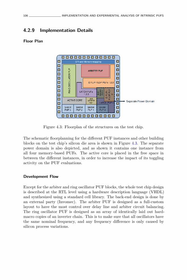
106 IMPLEMENTATION AND EXPERIMENTAL ANALYSIS OF INTRINSIC PUFS
4.2.9 Implementation Details
Floor Plan
Figure 4.3: Floorplan of the structures on the test chip.
The schematic floorplanning for the different PUF instances and other buildingblocks on the test chip’s silicon die area is shown in Figure 4.3. The separatepower domain is also depicted, and as shown it contains one instance fromall four memory-based PUFs. The active core is placed in the free space inbetween the different instances, in order to increase the impact of its togglingactivity on the PUF evaluations.
Development Flow
Except for the arbiter and ring oscillator PUF blocks, the whole test chip designis described at the RTL level using a hardware description language (VHDL)and synthesized using a standard cell library. The back-end design is done byan external party (Invomec). The arbiter PUF is designed as a full-customlayout to have the most control over delay line and arbiter circuit balancing.The ring oscillator PUF is designed as an array of identically laid out hard-macro copies of an inverter chain. This is to make sure that all oscillators havethe same nominal frequency, and any frequency difference is only caused bysilicon process variations.
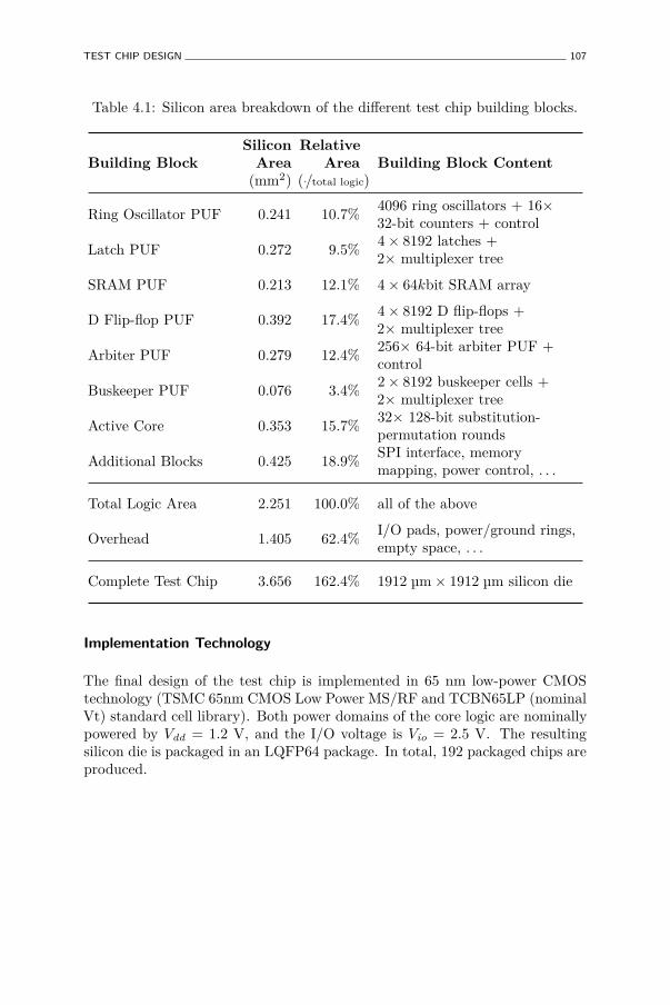
TEST CHIP DESIGN 107
Table 4.1: Silicon area breakdown of the different test chip building blocks.
Building BlockSilicon
Area(mm2)
RelativeArea
(./total logic)Building Block Content
Ring Oscillator PUF 0.241 10.7%4096 ring oscillators + 16×32-bit counters + control
Latch PUF 0.272 9.5%4× 8192 latches +2× multiplexer tree
SRAM PUF 0.213 12.1% 4× 64kbit SRAM array
D Flip-flop PUF 0.392 17.4%4× 8192 D flip-flops +2× multiplexer tree
Arbiter PUF 0.279 12.4%256× 64-bit arbiter PUF +control
Buskeeper PUF 0.076 3.4%2× 8192 buskeeper cells +2× multiplexer tree
Active Core 0.353 15.7%32× 128-bit substitution-permutation rounds
Additional Blocks 0.425 18.9%SPI interface, memorymapping, power control, . . .
Total Logic Area 2.251 100.0% all of the above
Overhead 1.405 62.4%I/O pads, power/ground rings,empty space, . . .
Complete Test Chip 3.656 162.4% 1912 µm× 1912 µm silicon die
Implementation Technology
The final design of the test chip is implemented in 65 nm low-power CMOStechnology (TSMC 65nm CMOS Low Power MS/RF and TCBN65LP (nominalVt) standard cell library). Both power domains of the core logic are nominallypowered by Vdd = 1.2 V, and the I/O voltage is Vio = 2.5 V. The resultingsilicon die is packaged in an LQFP64 package. In total, 192 packaged chips areproduced.
108 IMPLEMENTATION AND EXPERIMENTAL ANALYSIS OF INTRINSIC PUFS
Area Breakdown
Table 4.1 shows an estimate of the silicon die area breakdown of the differentbuilding blocks on the test chip. The estimates in this table are used inChapter 5 and Chapter 6 to estimate the required PUF size for a PUF basedapplication with given requirements. This provides an as objective as possiblecomparison between the different PUF constructions.
4.3 Experimental Uniqueness and Reproducibility
Results
4.3.1 Evaluation of Delay-based PUFs
Before we present the statistics of the experimental data, we first need todescribe the manner in which we evaluate bit responses for the delay-basedPUF constructions, i.e. the arbiter and the ring oscillator PUF. The evaluationof the memory-based PUFs follows trivially from their design.
Arbiter PUF Evaluation Modes
The basic arbiter PUF already produces single bit responses. We also consider2-XOR arbiter PUFs as proposed by Majzoobi et al. [100] by pairing up arbiterPUFs and perform an XOR-operation on their outputs to produce a singlebit response. The XOR-operation is not implemented on the test chip but isperformed off-line on the evaluated response bits of the basic arbiter PUFs.
Ring Oscillator PUF Evaluation Modes
As mentioned in Section 4.2.5, the ring oscillator PUF design outputs thefrequency counter values directly. While these values already show some PUFbehavior, it is difficult to use them as such in an application. For ease ofintegration, the frequency counter values need to be encoded in a meaningfulbinary response format. This will also make the comparison with the other PUFtypes more relevant. Ring oscillator PUF response bits are typically generatedbased on the relative comparisons between measured frequencies, as thesecomparison are much more resilient to noise and varying evaluation conditionsthan the absolute frequency values. We present two encoding methods basedon relative orderings of the frequency counter values.
EXPERIMENTAL UNIQUENESS AND REPRODUCIBILITY RESULTS 109
The first method is a basic pairwise comparison (P.C.) between countedfrequencies from different but simultaneously measured oscillators, as wasproposed by Suh and Devadas [138] (but without the 1-out-of-k maskingtechnique). A single response bit is generated based on the outcome of eachcomparison. To ensure independent responses, every oscillator is only usedfor the generation of a single bit. The arrangement of our ring oscillatorPUF design in 16 batches, with 256 oscillators and one frequency counter perbatch, allows to measure 16 frequencies simultaneously and hence produce 8response bits in one evaluation. Using this evaluation method, the completering oscillator PUF design can generate 256× 8 = 2048 response bits.
In [92], we developed a new response bit generation method for ring oscillatorPUFs based on the ordering of the measured frequencies. Suh and Devadas[138] and Yin and Qu [158] already observed that the amount of information inthe ordering of n independent and identically distributed frequencies is as highas log2 n!. If one can find an efficient and noise-resilient encoding of such anordering, this will lead to a significant increase in the number of independentresponse bits, since log2 n! =
∑ni=2 log2 i ≈ n · log2
ne
is superlinear in n, asopposed to the pairwise comparison method which can only produce a numberof response bits which is linear in n, i.e. n
2 .
In [92], we propose to use a Lehmer encoding [81, 129] to represent theascending order of a vector of simultaneously measured frequencies, followedby a Gray encoding [49] of the Lehmer coefficients. A Lehmer code isa unique numerical representation of an ordering (permutation) which ismoreover efficient to obtain since it does not require explicit value sorting.If fn = (f1, . . . , fn) is a vector containing n frequency measurements, then theLehmer code of the ascending order of these values is a coefficient vector rn−1 =(r1, . . . , rn−1) with ri ∈ {0, 1, . . . , i}. It is clear that rn−1 can take 2× 3× . . .×n = n! possible values which is exactly the number of possible orderings of fn,hence each ordering has a unique Lehmer code representation. The Lehmercoefficients are calculated from fn as rj =
∑ji=1 gt(fj+1, f ′i), with gt(x, y) = 1
if x > y and 0 otherwise. The Lehmer encoding has the nice property thata minimal change in the sorted ordering, caused by two neighboring valuesswapping places after sorting, only changes a single Lehmer coefficient by ±1.Using a binary Gray encoding for the Lehmer coefficients, this translates toonly a single bit difference, which makes the overall response bit generationparticularly noise resilient. The length of the binary representation becomes∑n
i=2⌈log2 i⌉ which is a nearly optimal representation of the actual amount ofinformation in the ordering, i.e.
∑ni=2 log2 i.
For our ring oscillator PUF design on the test chip, we apply this Lehmer-Gray(L.G.) encoding off-line on each vector of n = 16 simultaneously measuredfrequencies, yielding 49 response bits. In total, the ring oscillator PUF can
110 IMPLEMENTATION AND EXPERIMENTAL ANALYSIS OF INTRINSIC PUFS
generate 256 × 49 = 12544 response bits using this method, which is over sixtimes more than using the pairwise comparison method.
4.3.2 PUF Experiment: Goals, Strategy and Setup
Experiment Goals
The goal of the experiments on the test chip is to characterize the meaningfulproperties of the eight studied PUF constructions as realistically and asaccurately as possible. As explained in Section 4.1.1, it is not possible tomake a comprehensive ranking of the different PUFs solely based on theirbare characteristics. In order to make such an objective comparison, theenvisioned application needs to be taken into account as well. We will dothis respectively in Chapter 5 and Chapter 6 for PUF-based authenticationand PUF-based key generation. However, a common interface is desirable,i.e. a uniform set of characterization parameters for the meaningful propertiesof every PUF construction, which can be used in an unambiguous manner todetermine their usability in a particular application. Here, we will providesuch characterization parameters for the uniqueness and reproducibility of allstudied PUF constructions, respectively in Section 4.3.3 and in Section 4.3.4.The unpredictability of the different PUF constructions is discussed based onthe response entropy in Section 4.4.
Experiment Strategy and Setup
To realistically determine the behavior of the different PUFs, in particularregarding their reproducibility, they need to be tested under varying conditions.In particular, we consider variations in test chip’s supply voltage: Vdd =1.02 V . . . 1.32 V, and environment temperature: Tenv = −45 °C . . . 85 °C,during evaluation. These conditions are created by powering the test chip witha variable power supply and placing it in a climate chamber with temperaturecontrol. To comprehensibly assess the PUF’s behavior over these intervals, wetest it at the four extreme corner conditions:
• The low-low corner (LL) or αLL = (Tenv = −45 °C, Vdd = 1.02 V).
• The low-high corner (LH) or αLH = (Tenv = −45 °C, Vdd = 1.32 V).
• The high-low corner (HL) or αHL = (Tenv = 85 °C, Vdd = 1.02 V).
• The high-high corner (HH) or αHH = (Tenv = 85 °C, Vdd = 1.32 V).
EXPERIMENTAL UNIQUENESS AND REPRODUCIBILITY RESULTS 111
In addition, the test chip is also evaluated at the nominal reference condition:αref = (Tenv = 25 °C, Vdd = 1.20 V).
At all considered conditions, all PUF constructions on all Npuf = 192 test chipsare evaluated for all their possible challenges, except for the arbiter PUFs whichare only evaluated on a set of 256 randomly generated challenges. In fact,for the memory-based PUFs, the notion of ‘number of challenges’ is ratherarbitrary since it depends on how many bits one considers to be in a response,which we denote by ℓresp. In that respect, it is much more natural to detail thetotal number of generated response bits instead, denoted as Nbits ≡ Nchal × ℓresp.Since all considered evaluation methods for the delay-based PUFs also generatebitwise responses, we also describe them in this manner. For the arbiter PUFs,we consider all bits generated by all arbiter PUFs at the same time, hence forthe basic arbiter PUF experiment: Nbits = 256 × 256 = 65536, and for the2-XOR arbiter PUF: Nbits = 256×128 = 32768. All response bits are evaluatedNmeas = 20 times under each condition for all PUFs on all chips.
4.3.3 Experimental PUF Uniqueness Results
Uniqueness Quantifiers
As expressed in Definition 8, the uniqueness of a PUF class is determined by thedistribution of its inter-distance, in particular at nominal conditions. To studythis distribution, we calculate the inter-distances Dinter
Exp(P) on the measuredresponses for all PUF constructions and report the most important statisticson the observed inter-distances in Table 4.2. Since all responses are bitwise, allinter-distances are measured using Hamming distances. However, to make iteasier to compare the different PUF constructions, we report them as fractionalHamming distances, i.e. the Hamming distances are expressed as a ratio of thetotal number of evaluated response bits Nbits.
The basic inter-distance statistics we report in Table 4.2 are:
• The sample mean µinter
P and the sample standard deviation σinter
P , re-spectively expressing the location and dispersion of the inter-distancedistribution.
• The first percentile P [1%]inter
P of the samples and the sample minimummininter
P . These two order statistics give a good idea of the left tail of thedistribution, which is of interest when quantifying identifiability later.
In addition to these standard statistics, we introduce a custom statistic whichwill be of use later on: the inter-distance binomial probability estimator p̂inter
P .
112 IMPLEMENTATION AND EXPERIMENTAL ANALYSIS OF INTRINSIC PUFS
For many applications, we need to make assumptions about the distributionof the inter-distance of a PUF construction. In particular, we often needto extrapolate the observed empirical distribution to very small or largeprobabilities for which we have no reliable measurements. For efficiencyreasons it is important that this can be done as accurately as possible.However, any overestimation of the uniqueness could be disastrous for thesecurity requirements of an application and should be avoided at all cost.For extrapolations beyond the observed inter-distance values, we make theassumption that the inter-distance is binomially distributed with parameter p̂inter
P .This parameter is chosen to be as large as possible, but sufficiently small suchthat all three following constraints are met, with Fbino(x; n, p) the cumulativebinomial distribution function with parameters n and p, evaluated in x:
1. Fbino(µinter
P ·Nbits; Nbits, p̂inter
P ) ≥ 50%, i.e. the estimated binomial distributionshould produce values smaller than or equal to the observed sample meanwith a probability of at least 50%.
2. Fbino(P [1%]inter
P · Nbits; Nbits, p̂inter
P ) ≥ 1%, i.e. the estimated binomial distri-bution should produce values smaller than or equal to the observed firstpercentile with a probability of at least 1%. If this is not the case, valuessmaller than or equal to the first percentile of the samples are unlikely tooccur as often as they do in the experiment, which means the estimatedbinomial distribution is an overestimation.
3. Fbino(mininter
P ·Nbits; Nbits, p̂inter
P ) ≥ 10−6, i.e. the estimated binomial distribu-tion should produce values smaller than or equal to the observed sampleminimum with a probability of at least 10−6 (the total number of observedsamples is in the order of one million). If this is not the case, the observedsample minimum is unlikely to occur in the experiment according to theestimated binomial distribution, which is hence an overestimation.
The largest value for p̂inter
P meeting all these three constraints is computed for allthe PUF constructions and also reported in Table 4.2. When the inter-distanceis approximately binomially distributed, the value for p̂inter
P should closely matchµinter
P . When this is not the case, the three constraints make sure that thebinomial estimation based on p̂inter
P at least accurately models the left tail of theactual inter-distance distribution, to avoid overestimation for extrapolations tosmall probabilities.
Discussion on Uniqueness Results
When presented as fractional Hamming distance, the optimal inter-distanceis 50% which indicates two response bit vectors are maximally uncorrelated.
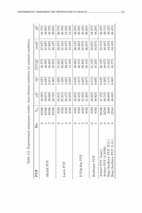
EXPERIMENTAL UNIQUENESS AND REPRODUCIBILITY RESULTS 113
Tab
le4.
2:E
xper
imen
tal
uniq
uene
ssre
sult
s:in
ter-
dist
ance
stat
isti
cs(a
tno
min
alco
ndit
ion)
.
PU
FN
o.
Nbit
sµ
inte
r
Pσ
inte
r
PP
[1%
]inte
r
Pm
inin
ter
Pp̂
inte
r
P
SRA
MP
UF
065
536
49.5
9%0.
33%
48.7
7%47
.82%
48.7
5%1
6553
649
.61%
0.33
%48
.76%
47.9
3%48
.86%
265
536
49.6
8%0.
31%
48.8
8%47
.80%
48.7
2%3
6553
649
.72%
0.30
%48
.94%
48.1
2%49
.04%
Lat
chP
UF
081
9234
.84%
1.20
%31
.82%
28.3
7%30
.77%
181
9237
.01%
1.23
%33
.86%
31.2
4%33
.70%
281
9233
.17%
1.62
%29
.31%
25.2
7%27
.59%
381
9216
.37%
2.02
%12
.10%
10.4
3%12
.10%
DF
lip-fl
opP
UF
081
9242
.35%
0.83
%40
.36%
38.1
4%40
.70%
181
9242
.42%
1.01
%40
.15%
38.2
0%40
.76%
281
9241
.88%
0.89
%39
.80%
37.8
7%40
.43%
381
9241
.20%
0.87
%39
.15%
36.9
5%39
.50%
Bus
keep
erP
UF
081
9248
.88%
0.71
%47
.12%
45.6
5%48
.27%
181
9248
.92%
0.69
%47
.23%
45.6
7%48
.28%
Arb
iter
PU
F(b
asic
)0
6553
647
.13%
0.44
%46
.13%
45.5
1%46
.43%
Arb
iter
PU
F(2
-XO
R)
032
768
49.7
4%0.
29%
49.0
7%48
.40%
49.7
1%R
ing
Osc
illat
orP
UF
(P.C
.)0
2048
49.6
0%1.
11%
47.0
2%44
.58%
49.5
4%R
ing
Osc
illat
orP
UF
(L.G
.)0
1254
446
.86%
0.48
%45
.77%
44.3
4%46
.45%
114 IMPLEMENTATION AND EXPERIMENTAL ANALYSIS OF INTRINSIC PUFS
A reported inter-distance sample mean (and binomial probability estimator)close to 50% hence indicates high uniqueness. In this respect, the SRAMPUF and the buskeeper PUF perform particularly well, whereas the D flip-flip PUF and the latch PUF show slightly reduced uniqueness. In particularlatch PUF instance number three, with an average inter-distance of merely16%, shows strikingly little uniqueness, even in comparison to the other latchPUF instances. This is a sign of a possible implementation error in latch thisinstance. The basic arbiter PUF shows high uniqueness which is an indicationthat the full-custom design approach succeeded in minimizing the arbiter PUFbias. For the 2-XOR arbiter PUF the uniqueness is evidently even higher.Both ring oscillator PUF evaluation methods also offer high uniqueness. Thepairwise comparison approach has slightly better uniqueness than the Lehmer-Gray encoding, but the latter method of course produces significantly moreresponse bits from the same amount of oscillators. For all the PUFs, thecomparison between the inter-distance sample mean and binomial probabilityestimator is also an indication of how closely their inter-distance distributionresembles a binomial distribution.
4.3.4 Experimental PUF Reproducibility Results
Reproducibility Quantifiers
The reproducibility of a PUF class is determined by the distribution of itsintra-distance (cf. Definition 7), in particular at the most extreme referencecorner conditions. To study these distribution, we calculate the intra-distancesDintra
Exp(P) on the measured responses for all PUF constructions at the referencecondition αref , and at all four corner conditions: αLL, αLH, αHL, αHH, and reportthe most important statistics on the observed intra-distances. Tables 4.3,4.4, 4.5, 4.6 and 4.7 respectively report the intra-distance statistics for theexperiments under conditions αref , αLL, αLH, αHL and αHH.
The basic intra-distance statistics we report in these tables are:
• The sample mean µintra
P and the sample standard deviation µintra
P , re-spectively expressing the location and dispersion of the intra-distancedistributions.
• The 99th percentile P [99%]intra
P of the samples and the sample maximummaxintra
P . These two order statistics give a good idea of the right tail of thedistribution, which is of interest when quantifying identifiability later.
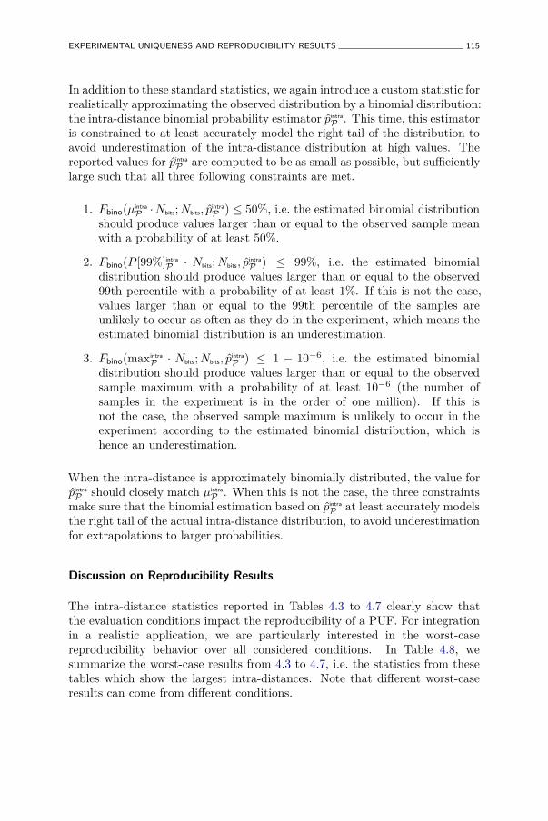
EXPERIMENTAL UNIQUENESS AND REPRODUCIBILITY RESULTS 115
In addition to these standard statistics, we again introduce a custom statistic forrealistically approximating the observed distribution by a binomial distribution:the intra-distance binomial probability estimator p̂intra
P . This time, this estimatoris constrained to at least accurately model the right tail of the distribution toavoid underestimation of the intra-distance distribution at high values. Thereported values for p̂intra
P are computed to be as small as possible, but sufficientlylarge such that all three following constraints are met.
1. Fbino(µintra
P ·Nbits; Nbits, p̂intra
P ) ≤ 50%, i.e. the estimated binomial distributionshould produce values larger than or equal to the observed sample meanwith a probability of at least 50%.
2. Fbino(P [99%]intra
P · Nbits; Nbits, p̂intra
P ) ≤ 99%, i.e. the estimated binomialdistribution should produce values larger than or equal to the observed99th percentile with a probability of at least 1%. If this is not the case,values larger than or equal to the 99th percentile of the samples areunlikely to occur as often as they do in the experiment, which means theestimated binomial distribution is an underestimation.
3. Fbino(maxintra
P · Nbits; Nbits, p̂intra
P ) ≤ 1 − 10−6, i.e. the estimated binomialdistribution should produce values larger than or equal to the observedsample maximum with a probability of at least 10−6 (the number ofsamples in the experiment is in the order of one million). If this isnot the case, the observed sample maximum is unlikely to occur in theexperiment according to the estimated binomial distribution, which ishence an underestimation.
When the intra-distance is approximately binomially distributed, the value forp̂intra
P should closely match µintra
P . When this is not the case, the three constraintsmake sure that the binomial estimation based on p̂intra
P at least accurately modelsthe right tail of the actual intra-distance distribution, to avoid underestimationfor extrapolations to larger probabilities.
Discussion on Reproducibility Results
The intra-distance statistics reported in Tables 4.3 to 4.7 clearly show thatthe evaluation conditions impact the reproducibility of a PUF. For integrationin a realistic application, we are particularly interested in the worst-casereproducibility behavior over all considered conditions. In Table 4.8, wesummarize the worst-case results from 4.3 to 4.7, i.e. the statistics from thesetables which show the largest intra-distances. Note that different worst-caseresults can come from different conditions.
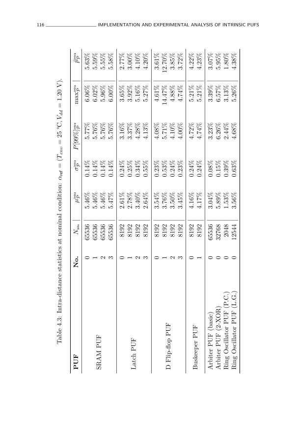
116 IMPLEMENTATION AND EXPERIMENTAL ANALYSIS OF INTRINSIC PUFS
Tab
le4.
3:In
tra-
dist
ance
stat
isti
csat
nom
inal
cond
itio
n:α
ref
=(T
en
v=
25°C
,Vd
d=
1.20
V).
PU
FN
o.
Nbit
sµ
intr
a
Pσ
intr
a
PP
[99%
]intr
a
Pm
axin
tra
Pp̂
intr
a
P
SRA
MP
UF
065
536
5.46
%0.
14%
5.77
%6.
06%
5.63
%1
6553
65.
46%
0.14
%5.
76%
6.02
%5.
59%
265
536
5.46
%0.
14%
5.76
%5.
96%
5.55
%3
6553
65.
47%
0.14
%5.
76%
6.00
%5.
58%
Lat
chP
UF
081
922.
61%
0.24
%3.
16%
3.65
%2.
77%
181
922.
78%
0.25
%3.
37%
3.92
%3.
00%
281
923.
40%
0.34
%4.
28%
5.16
%4.
10%
381
922.
64%
0.55
%4.
13%
5.27
%4.
20%
DF
lip-fl
opP
UF
081
923.
54%
0.23
%4.
08%
4.61
%3.
61%
181
923.
76%
0.53
%5.
71%
14.4
7%12
.70%
281
923.
50%
0.24
%4.
10%
4.88
%3.
85%
381
923.
45%
0.23
%4.
00%
4.74
%3.
72%
Bus
keep
erP
UF
081
924.
16%
0.24
%4.
72%
5.21
%4.
22%
181
924.
17%
0.24
%4.
74%
5.21
%4.
23%
Arb
iter
PU
F(b
asic
)0
6553
63.
04%
0.08
%3.
23%
3.39
%3.
07%
Arb
iter
PU
F(2
-XO
R)
032
768
5.89
%0.
15%
6.26
%6.
57%
5.95
%R
ing
Osc
illat
orP
UF
(P.C
.)0
2048
1.53
%0.
39%
2.44
%3.
13%
1.80
%R
ing
Osc
illat
orP
UF
(L.G
.)0
1254
43.
56%
0.63
%4.
68%
5.26
%4.
38%
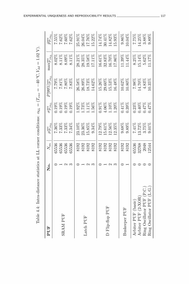
EXPERIMENTAL UNIQUENESS AND REPRODUCIBILITY RESULTS 117
Tab
le4.
4:In
tra-
dist
ance
stat
isti
csat
LL
corn
erco
ndit
ions
:α
LL
=(T
en
v=−
40°C
,Vd
d=
1.02
V).
PU
FN
o.
Nbit
sµ
intr
a
P;α
LL
σin
tra
P;α
LL
P[9
9%]in
tra
P;α
LL
max
intr
a
P;α
LL
p̂in
tra
P;α
LL
SRA
MP
UF
065
536
7.36
%0.
19%
7.79
%8.
02%
7.55
%1
6553
67.
33%
0.19
%7.
81%
8.11
%7.
62%
265
536
7.33
%0.
19%
7.80
%8.
09%
7.60
%3
6553
67.
34%
0.19
%7.
83%
8.11
%7.
62%
Lat
chP
UF
081
9223
.10%
1.92
%26
.58%
28.2
1%25
.91%
181
9223
.36%
1.73
%26
.89%
28.3
5%26
.04%
281
9215
.85%
1.11
%18
.73%
19.5
8%17
.76%
381
929.
34%
1.56
%14
.62%
17.1
1%15
.22%
DF
lip-fl
opP
UF
081
9212
.79%
0.91
%15
.26%
16.6
1%14
.74%
181
9215
.61%
4.06
%29
.60%
32.8
3%30
.41%
281
9212
.56%
1.10
%15
.53%
16.7
0%14
.82%
381
9212
.35%
1.20
%16
.48%
17.8
6%15
.93%
Bus
keep
erP
UF
081
929.
68%
0.41
%10
.62%
11.3
9%9.
86%
181
929.
89%
0.39
%10
.80%
11.4
4%10
.04%
Arb
iter
PU
F(b
asic
)0
6553
67.
41%
0.23
%7.
98%
8.25
%7.
75%
Arb
iter
PU
F(2
-XO
R)
032
768
13.7
2%0.
40%
14.7
0%15
.14%
14.2
5%R
ing
Osc
illat
orP
UF
(P.C
.)0
2048
3.75
%0.
47%
4.83
%5.
62%
3.88
%R
ing
Osc
illat
orP
UF
(L.G
.)0
1254
49.
01%
0.47
%10
.35%
11.1
7%9.
89%
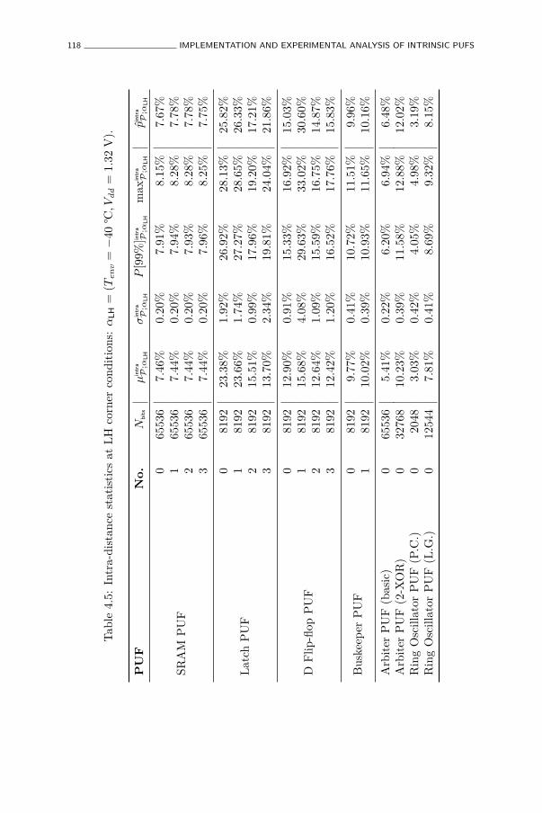
118 IMPLEMENTATION AND EXPERIMENTAL ANALYSIS OF INTRINSIC PUFS
Tab
le4.
5:In
tra-
dist
ance
stat
isti
csat
LH
corn
erco
ndit
ions
:α
LH
=(T
en
v=−
40°C
,Vd
d=
1.32
V).
PU
FN
o.
Nbit
sµ
intr
a
P;α
LH
σin
tra
P;α
LH
P[9
9%]in
tra
P;α
LH
max
intr
a
P;α
LH
p̂in
tra
P;α
LH
SRA
MP
UF
065
536
7.46
%0.
20%
7.91
%8.
15%
7.67
%1
6553
67.
44%
0.20
%7.
94%
8.28
%7.
78%
265
536
7.44
%0.
20%
7.93
%8.
28%
7.78
%3
6553
67.
44%
0.20
%7.
96%
8.25
%7.
75%
Lat
chP
UF
081
9223
.38%
1.92
%26
.92%
28.1
3%25
.82%
181
9223
.66%
1.74
%27
.27%
28.6
5%26
.33%
281
9215
.51%
0.99
%17
.96%
19.2
0%17
.21%
381
9213
.70%
2.34
%19
.81%
24.0
4%21
.86%
DF
lip-fl
opP
UF
081
9212
.90%
0.91
%15
.33%
16.9
2%15
.03%
181
9215
.68%
4.08
%29
.63%
33.0
2%30
.60%
281
9212
.64%
1.09
%15
.59%
16.7
5%14
.87%
381
9212
.42%
1.20
%16
.52%
17.7
6%15
.83%
Bus
keep
erP
UF
081
929.
77%
0.41
%10
.72%
11.5
1%9.
96%
181
9210
.02%
0.39
%10
.93%
11.6
5%10
.16%
Arb
iter
PU
F(b
asic
)0
6553
65.
41%
0.22
%6.
20%
6.94
%6.
48%
Arb
iter
PU
F(2
-XO
R)
032
768
10.2
3%0.
39%
11.5
8%12
.88%
12.0
2%R
ing
Osc
illat
orP
UF
(P.C
.)0
2048
3.03
%0.
42%
4.05
%4.
98%
3.19
%R
ing
Osc
illat
orP
UF
(L.G
.)0
1254
47.
81%
0.41
%8.
69%
9.32
%8.
15%

EXPERIMENTAL UNIQUENESS AND REPRODUCIBILITY RESULTS 119
Tab
le4.
6:In
tra-
dist
ance
stat
isti
csat
HL
corn
erco
ndit
ions
:α
HL
=(T
en
v=
85°C
,Vd
d=
1.02
V).
PU
FN
o.
Nbit
sµ
intr
a
P;α
HL
σin
tra
P;α
HL
P[9
9%]in
tra
P;α
HL
max
intr
a
P;α
HL
p̂in
tra
P;α
HL
SRA
MP
UF
065
536
7.28
%0.
15%
7.63
%7.
95%
7.46
%1
6553
67.
33%
0.15
%7.
70%
8.01
%7.
52%
265
536
7.33
%0.
16%
7.72
%7.
99%
7.50
%3
6553
67.
34%
0.14
%7.
68%
7.99
%7.
50%
Lat
chP
UF
081
9210
.62%
1.10
%14
.47%
17.9
6%16
.02%
181
9211
.99%
1.24
%15
.97%
19.4
3%17
.43%
281
9212
.51%
1.20
%15
.66%
17.0
4%15
.15%
381
927.
90%
1.45
%12
.42%
13.9
4%12
.21%
DF
lip-fl
opP
UF
081
9218
.10%
0.79
%20
.11%
21.0
3%19
.11%
181
9217
.95%
1.66
%21
.89%
23.7
1%21
.54%
281
9218
.27%
0.78
%20
.23%
21.0
8%19
.23%
381
9218
.15%
0.81
%19
.96%
20.8
4%18
.96%
Bus
keep
erP
UF
081
9217
.71%
0.90
%20
.06%
21.1
4%19
.07%
181
9217
.60%
0.91
%19
.95%
21.0
3%18
.97%
Arb
iter
PU
F(b
asic
)0
6553
65.
23%
0.21
%5.
91%
6.29
%5.
86%
Arb
iter
PU
F(2
-XO
R)
032
768
9.90
%0.
37%
11.1
3%11
.83%
11.0
0%R
ing
Osc
illat
orP
UF
(P.C
.)0
2048
2.84
%0.
40%
3.81
%4.
54%
2.98
%R
ing
Osc
illat
orP
UF
(L.G
.)0
1254
47.
11%
0.42
%8.
10%
9.19
%8.
03%
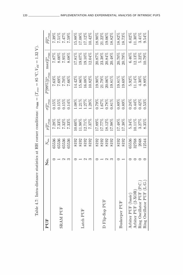
120 IMPLEMENTATION AND EXPERIMENTAL ANALYSIS OF INTRINSIC PUFS
Tab
le4.
7:In
tra-
dist
ance
stat
isti
csat
HH
corn
erco
ndit
ions
:α
HH
=(T
en
v=
85°C
,Vd
d=
1.32
V).
PU
FN
o.
Nbit
sµ
intr
a
P;α
HH
σin
tra
P;α
HH
P[9
9%]in
tra
P;α
HH
max
intr
a
P;α
HH
p̂in
tra
P;α
HH
SRA
MP
UF
065
536
7.28
%0.
15%
7.63
%7.
87%
7.39
%1
6553
67.
33%
0.15
%7.
69%
8.00
%7.
51%
265
536
7.32
%0.
15%
7.70
%7.
95%
7.47
%3
6553
67.
33%
0.14
%7.
66%
8.08
%7.
59%
Lat
chP
UF
081
9210
.60%
1.08
%14
.42%
17.8
1%15
.88%
181
9211
.98%
1.21
%15
.86%
19.0
7%17
.08%
281
9212
.71%
1.27
%16
.08%
19.1
0%17
.12%
381
927.
37%
1.28
%10
.82%
12.0
4%10
.42%
DF
lip-fl
opP
UF
081
9217
.89%
0.79
%19
.90%
20.8
7%18
.90%
181
9217
.77%
1.67
%21
.79%
23.3
8%21
.22%
281
9218
.12%
0.78
%20
.06%
20.8
4%19
.06%
381
9217
.98%
0.81
%19
.81%
20.4
8%18
.82%
Bus
keep
erP
UF
081
9217
.48%
0.89
%19
.81%
20.7
0%18
.82%
181
9217
.38%
0.89
%19
.69%
20.7
9%18
.73%
Arb
iter
PU
F(b
asic
)0
6553
65.
34%
0.24
%5.
92%
6.46
%6.
02%
Arb
iter
PU
F(2
-XO
R)
032
768
10.1
1%0.
44%
11.1
4%12
.13%
11.3
0%R
ing
Osc
illat
orP
UF
(P.C
.)0
2048
3.27
%0.
42%
4.30
%5.
22%
3.41
%R
ing
Osc
illat
orP
UF
(L.G
.)0
1254
48.
35%
0.53
%9.
89%
10.7
9%9.
54%

EXPERIMENTAL UNIQUENESS AND REPRODUCIBILITY RESULTS 121
Tab
le4.
8:W
orst
-cas
ein
tra-
dist
ance
stat
isti
csov
eral
lfo
urco
rner
s(α
WC).
PU
FN
o.
Nbit
sµ
intr
a
P;α
WC
P[9
9%]in
tra
P;α
WC
max
intr
a
P;α
WC
p̂in
tra
P;α
WC
SRA
MP
UF
065
536
7.46
%7.
91%
8.15
%7.
67%
165
536
7.44
%7.
94%
8.28
%7.
78%
265
536
7.44
%7.
93%
8.28
%7.
78%
365
536
7.44
%7.
96%
8.25
%7.
75%
Lat
chP
UF
081
9223
.38%
26.9
2%28
.21%
25.9
1%1
8192
23.6
6%27
.27%
28.6
5%26
.33%
281
9215
.85%
18.7
3%19
.58%
17.7
6%3
8192
13.7
0%19
.81%
24.0
4%21
.86%
DF
lip-fl
opP
UF
081
9218
.10%
20.1
1%21
.03%
19.1
1%1
8192
17.9
5%29
.63%
33.0
2%30
.60%
281
9218
.27%
20.2
3%21
.08%
19.2
3%3
8192
18.1
5%19
.96%
20.8
4%18
.96%
Bus
keep
erP
UF
081
9217
.71%
20.0
6%21
.14%
19.0
7%1
8192
17.6
0%19
.95%
21.0
3%18
.97%
Arb
iter
PU
F(b
asic
)0
6553
67.
41%
7.98
%8.
25%
7.75
%A
rbit
erP
UF
(2-X
OR
)0
3276
813
.72%
14.7
0%15
.14%
14.2
5%R
ing
Osc
illat
orP
UF
(P.C
.)0
2048
3.75
%4.
83%
5.62
%3.
88%
Rin
gO
scill
ator
PU
F(L
.G.)
012
544
9.01
%10
.35%
11.1
7%9.
89%
122 IMPLEMENTATION AND EXPERIMENTAL ANALYSIS OF INTRINSIC PUFS
Studying the worst-case intra-distance statistics in Table 4.8, we see thatof all the memory-based PUF constructions the SRAM PUF is particularlyreproducible, with even worst-case maximal intra-distances smaller than10%. The buskeeper, D flip-flop and latch PUFs have a considerably worsereproducibility. We also remark two outlying behaviors:
1. Latch PUF instances number two and three show lower intra-distancesthan the other two, which is a side-effect of them already having lowuniqueness. This is most likely a result of an implementation fault in theseinstances, which we also already spotted based on the outlying uniquenessresults. Note that latch instances number two and three deploy the rathercomplex scan-chain based read-out technique, as opposed to the other twowhich use a multiplexer tree, which is likely the cause of this problem.
2. D flip-flop PUF instance number one shows considerably larger intra-distances than the other three instances. The cause for this is unknown,but is likely also due to an implementation fault.
To avoid that these outlying results affect this objective comparison betweendifferent PUF constructions, we will ignore them in all following analysis.
The delay-based PUFs also show relatively good reproducibility. The worst-casestatistics of the basic arbiter PUF are nearly identical to those of the SRAMPUF. For the 2-XOR arbiter PUF, the intra-distances get approximately twiceas large, which follows from their construction: when one of both XOR-edarbiter PUFs produces a faulty bit, the XOR-ed result will also be wrong. Thering oscillator PUF response bits based on pairwise comparison of frequencies isextremely reproducible, which proves the strength of this method. The Lehmer-Gray encoding method has worse reproducibility than the pairwise comparisonmethod, but is still fairly good with a worst-case average smaller than 10%.
4.4 Assessing Entropy
For many applications, and in particular for PUF-based key generation, itis important to accurately estimate the entropy of a random PUF response.Entropy is a function of the distribution of a random variable and expressesthe amount of uncertainty one has about the outcome of the random variable.In the case of PUF responses, it represents a generalized and unconditionalupper bound on the average predictability of an unobserved random outcomeY of a response evaluation. However, in general it is also very difficult or evenimpossible to calculate the entropy of a PUF response exactly. In the end,
ASSESSING ENTROPY 123
the distribution of most PUF responses is determined by very complex andeven chaotic physical processes, and it cannot be learned in the complete detailwhich is required to calculate its entropy exactly. Typically, only estimatedupper bounds on the underlying entropy can be provided. These bounds areeither derived from a high-level physical model of the PUF construction, orbased on the experimental data one observes.
In this section, we will present increasingly tighter upper bounds on theentropy of a PUF response based on increasingly more powerful adversarymodels, i.e. adversaries which gain more and more insight into the underlyingdistribution of the PUF’s responses. We do this for all eight PUF constructionsstudied on the test chip and we compute entropy bounds based on theexperimentally observed response distributions of these PUFs.
4.4.1 Adversary Models and Basic Entropy Bounds
In the following, Y n represents a random bit vector of length n, and Yi ← {0, 1}is a binary random variable whose distribution is completely determinedby pi
△
= Pr (Yi = 1). We also use the following notation for the conditionaldistribution of Yi conditioned on the previous bits Y (i−1) = (Y1, . . . , Y(i−1)):
pi|y(i−1)△
= Pr(Yi = 1|Y (i−1) = y(i−1)
). An overview of the general notions of
probability theory and information theory used in this section is found inAppendix A.
Completely Ignorant Adversary
An adversary which is completely ignorant of the underlying distribution of theresponses can make no better prediction than just guessing every bit completelyat random. To him, it looks as if the PUF response has full entropy. Based onthis adversary, we can introduce the following trivial response entropy bound:
H(Y n) ≤ n .
Using entropy density, this bound is denoted as
ρignorant(Yn)
△
= 100% ,
such that ρ(Y n) ≤ ρignorant(Y n). This ignorant entropy bound is very trivial,but we include it nonetheless for completeness and to detail the manner inwhich we will discuss the following bounds.
124 IMPLEMENTATION AND EXPERIMENTAL ANALYSIS OF INTRINSIC PUFS
Adversary Knows Global Bias
The most basic deviation from a completely uniform and independentdistribution of the response bits is caused by an overall global bias, i.e. onaverage every bit is more likely to be either ’0’ or ’1’. Such a global bias in theresponse Y n can be expressed as:
pglobalbias =1n
E
[n∑
i=1
Yi
].
An adversary with knowledge of this global bias can make better than randompredictions by guessing in favor of the bias, i.e. if pglobalbias < 50% he predicts a‘0’ and else a ‘1’. To him, it looks as if all PUF response bits are independentand identically distributed (i.i.d.) according to a Bernoulli distribution withparameter pglobalbias. Based on such an adversary, the following response entropybound is introduced:
H(Y n) ≤ n · h(pglobalbias) .
This global bias entropy bound is expressed using entropy density as ρ(Y n) ≤ρglobalbias(Y n), with:
ρglobalbias(Yn)
△
= h(pglobalbias) .
Adversary Knows Bit-dependent Bias
In a more realistic setting, every bit position in a PUF response vector willhave its own bias, as expressed by pi = Pr (yi = 1). An adversary knowingthese individual bit-dependent biases can make a more accurate prediction byguessing individual bits in favor of these biases. To him, it looks as if all PUFresponse bits are independently, but no longer identically distributed, with eachbit sampled from its own Bernoulli distribution with parameter pi. Taking intoaccount this adversary, the response entropy bound can be refined further:
H(Y n) ≤n∑
i=1
h(pi) .
Again we rewrite this bit-dependent bias entropy bound using entropy densityas ρ(Y n) ≤ ρbitbias(Y n), with:
ρbitbias(Yn)
△
=1n
n∑
i=1
h(pi) .
ASSESSING ENTROPY 125
Adversary Knows Inter-bit Dependencies
In the previous three adversary models, we moved from an adversary whosees a PUF response as an i.i.d. uniformly random bit vector to one whoobserves it as a vector of independently distributed bits which are no longeruniform or identically distributed. The next improvement to the adversarymodel would be to give him insight into the dependencies between differentresponse bits, i.e. he does no longer assume that the response bits are completelyindependently distributed. It is clear that full knowledge of all inter-bitdependencies is generally unattainable since that would give the complete andexact distribution of the responses. Instead, we assume an adversary whichhas a certain realistic yet only partial model of the inter-bit dependencies. Weconsider two such partial dependency models:
1. The adversary has insight in the pairwise joint distributions p(yi, yj) ofall possible pairs of response bits in Y n. This is a natural extension ofinsight in the bit-dependent bias of individual bits.
2. The adversary has partial insight in the conditional distribution p(yi|y(i−1))
of a response bit Yi given the observation of the previous response bitsY (i−1) = y(i−1). This is typically the case when the adversary deploysa successful next-bit modeling attack on response bits, with a predictionmodel which is trained on earlier observed responses.
We discuss both these adversarial models separately.
Adversary Knows Pairwise Joint Distributions
When an adversary knows all pairwise joint distributions between the responsebits in Y n, the response entropy bound is further lowered to:
H(Y n) ≤n∑
i=1
h(pi)−n−1∑
i=1
I(Yi; Yi+1) .
We call this the pairwise joint distribution entropy bound and using entropydensity, we write ρ(Y n) ≤ ρpairjoint(Y n), with:
ρpairjoint(Yn)
△
=1n
(n∑
i=1
h(pi)−n−1∑
i=1
I(Yi; Yi+1)
).
The mutual information values, i.e. the information shared by consecutivepairs of random bits, is subtracted from the bit-dependent bias entropy bound
126 IMPLEMENTATION AND EXPERIMENTAL ANALYSIS OF INTRINSIC PUFS
since they are in a way counted twice. The mutual information between twoconsecutive random bits can be computed from their pairwise joint distribution.Note that the subtracted amount is dependent on the way the individualrandom bit variables are ordered in Y n, since the mutual information iscomputed over consecutive pairs (Yi, Yi+1) from Y n = (Y1, . . . , Yn). Withoutloss of generalization, we assume that the bits are ordered in such a way as tomaximize the subtracted amount. This yields the tightest lower bound on theresponse entropy.
Adversary Deploys Next-Bit Modeling Attack
In this model, we assume an adversary can perform a modeling attack on thePUF response bits, which after having been trained with (i − 1) previouslyobserved response bits, can predict the i-th bit with an average successprobability of pmodel(i). This results in a response entropy bound of:
H(Y n) ≤n∑
i=1
h(pmodel(i)) .
We call this the model entropy bound, and in terms of entropy density thisbecomes ρ(Y n) ≤ ρmodel(Y n), with:
ρmodel(Yn)
△
=1n
n∑
i=1
h(pmodel(i)) .
The tightness of this bound depends on the strength of the assumed model, andhence on the information and computational power available to the adversaryin order to build this model. The goal of the model is to exploit dependenciesbetween bits in order to make a better than random prediction for the next bit.In general, the model’s success rate gets better and better as it is trained onmore responses, i.e. pmodel(i) increases with i. This also means that ρmodel(Y n),unlike for the previous discussed bounds, is not a constant, but is dependenton n. In general, ρmodel(Y n) decreases for increasing n. For example, if a modelproduces near perfect predictions after having been trained with a large numberof observed response bits, all following response bits will no longer contributeany meaningful entropy since they are perfectly predictable. Hence, producingmore response bits will only increase the response length and not its entropy,i.e. the entropy density of the response decreases.
ASSESSING ENTROPY 127
4.4.2 Entropy Bound Estimations Based on ExperimentalResults
Next, we evaluate the different discussed entropy bounds on the measuredresponses obtained from the performed experiments which were discussed inSection 4.3. All entropy bounds are expressed using entropy density to allowan easy comparison between different PUF constructions.
Bound Estimation Strategy
For all memory-based PUF instances, we consider a response bit vectorcontaining n = 5000 bits to estimate the following entropy bounds:
• The ignorant entropy bound is trivially equal to 100% for all PUFs.
• For the global bias entropy bound, we estimate the global bias bycomputing the response bit sample mean over all 5000 considered bitson all 192 devices.
• For the bit-dependent bias entropy bound, we estimate the bit-dependentbiases by computing the response bit sample mean over all 192 devicesfor every bit individually.
• For the pairwise distribution entropy bound, we estimate the pairwisejoint distributions of all possible pairs of the considered response bits,by counting the occurrences of each of the four possible outcomes (0, 0),(0, 1), (1, 0) or (1, 1) for each considered pair on all 192 devices.
We do not consider the model entropy bound for memory-based PUFs, as nosuccessful modeling attacks on memory-based PUFs are known. All boundestimations are done based on responses measured at nominal conditions.
For the delay-based PUF instances, we differentiate between the arbiter andthe ring oscillator PUFs. For both response generation methods of the ringoscillator PUF, we perform the same bound estimations as for the memory-based PUFs, only on different sizes of response bit vectors, respectively n =2048 for the pairwise comparison method and n = 12544 for the Lehmer-Graymethod. No model-building attacks for these ring oscillator PUFs are known.
For the arbiter PUF we take a slightly different approach. The first four boundsare computed for response bit vectors of only n = 256 bits, for each of the 256arbiter PUF instances and 128 2-XOR arbiter PUF instances on the test chipindividually, but we report only the results for the worst observed instance.
128 IMPLEMENTATION AND EXPERIMENTAL ANALYSIS OF INTRINSIC PUFS
Besides these four bounds, we also consider the model entropy bound for bothtypes of arbiter PUFs. This is discussed in more detail in Section 4.4.3.
Bound Estimation Results
The results for the estimations of the ignorant entropy bound, the globalbias entropy bound, the bit-dependent bias entropy bound and the pairwisedistribution entropy bound are presented in Table 4.9. From these results, it isevident that these four estimates represent consecutively tighter upper boundson the real response entropy.
4.4.3 Modeling Attacks on Arbiter PUFs
From the initial introduction of arbiter PUFs, it was recognized that they aresusceptible to modeling attacks. This is a result of the reduced complexity ofthe dependency between arbiter PUF challenges and responses. For the basicarbiter PUF it was made clear, e.g. by Lee et al. [80], that this dependency is toa high level of accuracy even a linear system. In that case, the unpredictabilityof the responses results only from the unknown parameters of this underlyingsystem, since once they are learned every response bit is easily predictablewith high accuracy. A modeling attack attempts to estimate the unknownmodel parameters as a function of observed challenge-response pairs. Formore advanced arbiter PUF constructions, e.g. the 2-XOR arbiter PUF, theunderlying model becomes more complex, but as shown by Rührmair et al.[123], it is still modelable with more advanced modeling techniques.
Modeling with Machine Learning Techniques
A particularly interesting set of modeling techniques are based on machinelearning [104]. Machine learning algorithms are able to automatically learncomplex behavior and unknown model parameters by generalizing on presentedtraining examples. Another strong motivation for using machine learningalgorithms in modeling attacks is that they are generic, i.e. they have the abilityto learn any complex behavior and are not a-priori restricted to a particularmodel description (e.g. a linear model).
In [60], we apply two basic machine learning techniques to our experimentalarbiter PUF results to test for modelability: i) artificial neural networks orANNs [104], and ii) support-vector machines or SVMs [32]. Both techniqueshave been demonstrated to be able to effectively model basic arbiter PUFs,
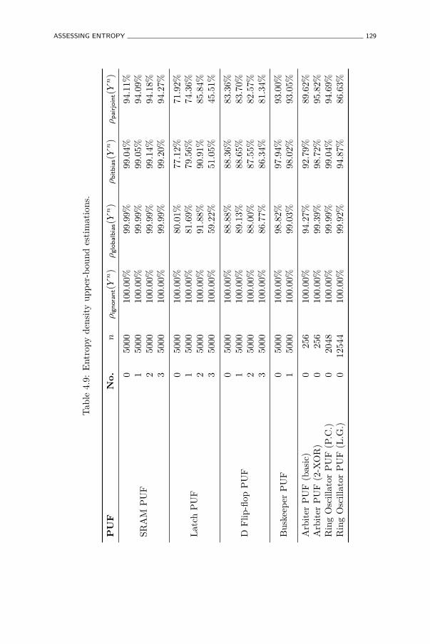
ASSESSING ENTROPY 129
Tab
le4.
9:E
ntro
pyde
nsit
yup
per
-bou
ndes
tim
atio
ns.
PU
FN
o.
nρ
ignora
nt(
Yn)
ρglo
balb
ias(
Yn)
ρbit
bia
s(Y
n)
ρpair
join
t(Y
n)
SRA
MP
UF
050
0010
0.00
%99
.99%
99.0
4%94
.11%
150
0010
0.00
%99
.99%
99.0
5%94
.09%
250
0010
0.00
%99
.99%
99.1
4%94
.18%
350
0010
0.00
%99
.99%
99.2
0%94
.27%
Lat
chP
UF
050
0010
0.00
%80
.01%
77.1
2%71
.92%
150
0010
0.00
%81
.69%
79.5
6%74
.36%
250
0010
0.00
%91
.88%
90.9
1%85
.84%
350
0010
0.00
%59
.22%
51.0
5%45
.51%
DF
lip-fl
opP
UF
050
0010
0.00
%88
.88%
88.3
6%83
.36%
150
0010
0.00
%89
.13%
88.6
5%83
.70%
250
0010
0.00
%88
.00%
87.5
5%82
.57%
350
0010
0.00
%86
.77%
86.3
4%81
.34%
Bus
keep
erP
UF
050
0010
0.00
%98
.82%
97.9
4%93
.00%
150
0010
0.00
%99
.03%
98.0
2%93
.05%
Arb
iter
PU
F(b
asic
)0
256
100.
00%
94.2
7%92
.79%
89.6
2%A
rbit
erP
UF
(2-X
OR
)0
256
100.
00%
99.3
9%98
.72%
95.8
2%R
ing
Osc
illat
orP
UF
(P.C
.)0
2048
100.
00%
99.9
9%99
.04%
94.6
9%R
ing
Osc
illat
orP
UF
(L.G
.)0
1254
410
0.00
%99
.92%
94.8
7%86
.63%
130 IMPLEMENTATION AND EXPERIMENTAL ANALYSIS OF INTRINSIC PUFS
respectively by Gassend et al. [48] and Rührmair et al. [123]. However, weapply these attacks on PUF responses resulting from a modern implementation(65 nm CMOS), as opposed to these earlier results which work with oldertechnologies [48] or only with simulated data [123]. For this analysis of themodel entropy bound, we are mainly interested in the results of these modelingattacks. For more details on their implementation, we refer to [60].
Modeling Results
Using both ANN and SVM, we were able to successfully model both basic and2-XOR arbiter PUFs. Both ANN and SVM first take a number of known arbiterPUF challenge-response pairs which they use to train their model. Afterwards,their modeling performance is evaluated by their success rate of accuratelypredicting unobserved responses when presented with a challenge from a largetest set. It is evident that, the more training examples a machine learningalgorithm is allowed to use, the better its modeling accuracy becomes. InFigure 4.4, we summarize the outcome of our machine learning modeling attackson the experimental data from the basic and the 2-XOR arbiter PUFs. It showsthe average success rate (pmodel(i)) of the best machine learning technique, ANNor SVM, after having been trained with (i− 1) earlier observed response bits.
We can draw some conclusions on the machine learning results as representedin Figure 4.4:
• The 2-XOR arbiter PUF is more difficult to model with our techniquesthan the basic arbiter PUF, as expressed by the larger number of trainingexamples required to achieve the same modeling success rate. This is aresult of the challenge-response relation being more complex for the 2-XOR arbiter PUF.
• The basic arbiter PUF can be modeled with ≈ 90% accuracy aftertraining with ≈ 500 examples and with ≈ 95% accuracy after trainingwith ≈ 2000 examples. Note that the maximal attainable success rateof any modeling attack is naturally limited by the reproducibility ofthe considered PUF instance. In that respect, the obtained modelingaccuracy of ≈ 97% after training with ≈ 5000 examples can be consideredperfect, given that the average intra-distance of the basic arbiter PUF atnominal conditions is about 3% (cf. Table 4.3). This means that allfollowing response bits do not contribute any entropy except for theirreproducibility uncertainty.
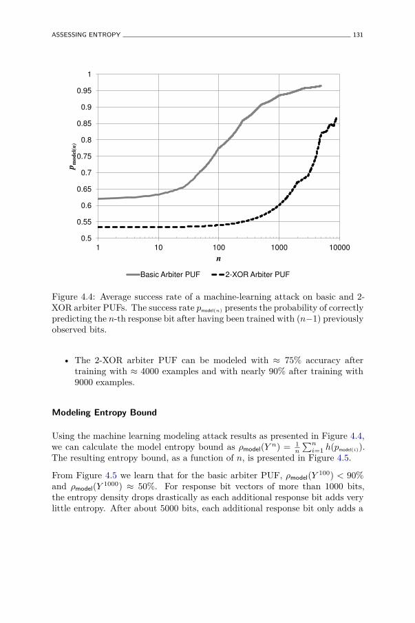
ASSESSING ENTROPY 131
0.5
0.55
0.6
0.65
0.7
0.75
0.8
0.85
0.9
0.95
1
1 10 100 1000 10000
pmodel(
n)
n
Basic Arbiter PUF 2-XOR Arbiter PUF
Figure 4.4: Average success rate of a machine-learning attack on basic and 2-XOR arbiter PUFs. The success rate pmodel(n) presents the probability of correctlypredicting the n-th response bit after having been trained with (n−1) previouslyobserved bits.
• The 2-XOR arbiter PUF can be modeled with ≈ 75% accuracy aftertraining with ≈ 4000 examples and with nearly 90% after training with9000 examples.
Modeling Entropy Bound
Using the machine learning modeling attack results as presented in Figure 4.4,we can calculate the model entropy bound as ρmodel(Y n) = 1
n
∑ni=1 h(pmodel(i)).
The resulting entropy bound, as a function of n, is presented in Figure 4.5.
From Figure 4.5 we learn that for the basic arbiter PUF, ρmodel(Y 100) < 90%and ρmodel(Y 1000) ≈ 50%. For response bit vectors of more than 1000 bits,the entropy density drops drastically as each additional response bit adds verylittle entropy. After about 5000 bits, each additional response bit only adds a
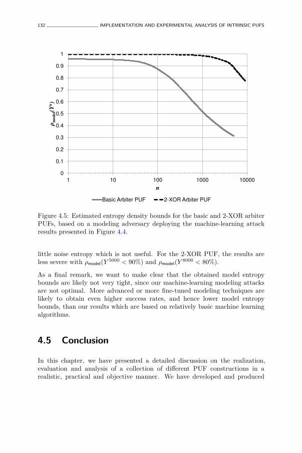
132 IMPLEMENTATION AND EXPERIMENTAL ANALYSIS OF INTRINSIC PUFS
0
0.1
0.2
0.3
0.4
0.5
0.6
0.7
0.8
0.9
1
1 10 100 1000 10000
!model(
Yn)
n
Basic Arbiter PUF 2-XOR Arbiter PUF
Figure 4.5: Estimated entropy density bounds for the basic and 2-XOR arbiterPUFs, based on a modeling adversary deploying the machine-learning attackresults presented in Figure 4.4.
little noise entropy which is not useful. For the 2-XOR PUF, the results areless severe with ρmodel(Y 5000 < 90%) and ρmodel(Y 8000 < 80%).
As a final remark, we want to make clear that the obtained model entropybounds are likely not very tight, since our machine-learning modeling attacksare not optimal. More advanced or more fine-tuned modeling techniques arelikely to obtain even higher success rates, and hence lower model entropybounds, than our results which are based on relatively basic machine learningalgorithms.
4.5 Conclusion
In this chapter, we have presented a detailed discussion on the realization,evaluation and analysis of a collection of different PUF constructions in arealistic, practical and objective manner. We have developed and produced
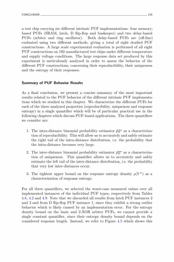
CONCLUSION 133
a test chip carrying six different intrinsic PUF implementations: four memory-based PUFs (SRAM, latch, D flip-flop and buskeeper) and two delay-basedPUFs (arbiter and ring oscillator). Both delay-based PUFs are (off-line)evaluated using two different methods, giving a total of eight studied PUFconstructions. A large scale experimental evaluation is performed of all eightPUF constructions on 192 manufactured test chips under different temperatureand supply voltage conditions. The large response data set produced by thisexperiment is meticulously analyzed in order to assess the behavior of thedifferent PUF constructions, concerning their reproducibility, their uniquenessand the entropy of their responses.
Summary of PUF Behavior Results
As a final conclusion, we present a concise summary of the most importantresults related to the PUF behavior of the different intrinsic PUF implementa-tions which we studied in this chapter. We characterize the different PUFs foreach of the three analyzed properties (reproducibility, uniqueness and responseentropy) in a single quantifier which will be of particular practical use in thefollowing chapters which discuss PUF-based applications. The three quantifierswe consider are:
1. The intra-distance binomial probability estimator p̂intra
P as a characteriza-tion of reproducibility. This will allow us to accurately and safely estimatethe right tail of the intra-distance distribution, i.e. the probability thatthe intra-distance becomes very large.
2. The inter-distance binomial probability estimator p̂inter
P as a characteriza-tion of uniqueness. This quantifier allows us to accurately and safelyestimate the left tail of the inter-distance distribution, i.e. the probabilitythat very low inter-distances occur.
3. The tightest upper bound on the response entropy density ρ(Y n) as acharacterization of response entropy.
For all three quantifiers, we selected the worst-case measured values over allimplemented instances of the individual PUF types, respectively from Tables4.8, 4.2 and 4.9. Note that we discarded all results from latch PUF instances 2and 3 and from D flip-flop PUF instance 1, since they exhibit a strong outlierbehavior which is likely caused by an implementation error. For the entropydensity bound on the basic and 2-XOR arbiter PUFs, we cannot provide asingle constant quantifier, since their entropy density bound depends on theconsidered response length. Instead, we refer to Figure 4.5 which shows this
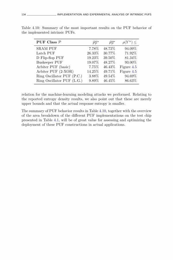
134 IMPLEMENTATION AND EXPERIMENTAL ANALYSIS OF INTRINSIC PUFS
Table 4.10: Summary of the most important results on the PUF behavior ofthe implemented intrinsic PUFs.
PUF Class P p̂intra
P p̂inter
P ρ(Y n) ≤
SRAM PUF 7.78% 48.72% 94.09%Latch PUF 26.33% 30.77% 71.92%D Flip-flop PUF 19.23% 39.50% 81.34%Buskeeper PUF 19.07% 48.27% 93.00%Arbiter PUF (basic) 7.75% 46.43% Figure 4.5Arbiter PUF (2-XOR) 14.25% 49.71% Figure 4.5Ring Oscillator PUF (P.C.) 3.88% 49.54% 94.69%Ring Oscillator PUF (L.G.) 9.89% 46.45% 86.63%
relation for the machine-learning modeling attacks we performed. Relating tothe reported entropy density results, we also point out that these are merelyupper bounds and that the actual response entropy is smaller.
The summary of PUF behavior results in Table 4.10, together with the overviewof the area breakdown of the different PUF implementations on the test chippresented in Table 4.1, will be of great value for assessing and optimizing thedeployment of these PUF constructions in actual applications.
Chapter 5
PUF-based EntityIdentification andAuthentication
Human beings are given free will in order to choosebetween insanity on the one hand and lunacy on theother.
Brave New WorldAldous Huxley
5.1 Introduction
5.1.1 Motivation
Due to their combination of uniqueness and reproducibility, a PUF embeddedby an entity serves as an identifying feature of that entity, as already intuitivelyexpressed by Definition 9. Moreover, the physical unclonability exhibited by anembedded PUF construction provides even strong security guarantees regardingthis expressed identity, which could be used for authentication purposes.However, in order to be of any practical value, the security and robustness
135
136 PUF-BASED ENTITY IDENTIFICATION AND AUTHENTICATION
of a PUF-based identification or authentication needs to be quantified basedon their experimentally verified behavioral characteristics.
Entity Authentication
In information security, the term ‘authentication’ has a very broad meaning,which often leads to confusion when not described in more detail. First of all,authentication can relate to entities or to data. In the former case one speaksof entity authentication, while the latter is called message authentication. Sincea PUF provides a measure of an entity-specific physical feature, we particularlyconsider entity authentication in this chapter. Whenever we talk about PUF-based authentication, entity authentication is implied.
Entity authentication by itself is still a catchall for a collection of techniquesused to check and be assured of the identity of an entity. The Handbook ofApplied Cryptography [102] defines entity authentication as:
Definition 25. An entity authentication technique assures one party, throughacquisition of corroborative evidence, of both: i) the identity of a second partyinvolved, and ii) that the second party was active at the time the evidence wascreated or acquired.
Besides convincing proof of its identity, an entity authentication technique alsoneeds to guarantee that the authenticating entity is actively present in theauthentication.
Identification
The Handbook of Applied Cryptography [102] treats ‘identification’ and ‘entityauthentication’ as synonyms. However, in this thesis, as in many other treatisesof the subject, we consider identification to be a related but significantly weakerconcept than authentication (see also [102, Remark 10.2]). Identification isthe mere claiming or stating of its identity, without necessarily presentingany convincing proof thereof. While not strictly a security technique sinceit doesn’t fulfill any meaningful security objective, identification still has veryuseful qualities:
• Identification is in many cases a necessary precondition for entityauthentication and hence an inherent part of most entity authentication
INTRODUCTION 137
techniques. An entity that cannot be identified, cannot be individuallyauthenticated.1
• For applications without strict security objectives, identification can bea sufficient condition, e.g. for applications which involve the tracking ofproducts in a closed system.
• In certain situations, identification is sufficient to achieve entity authen-tication, since the authentication conditions are implicitly met.
For this reason, we will first discuss PUF-based identification in this chapter,before we treat PUF-based authentication.
5.1.2 Chapter Goals
The primary goal of this chapter is to propose practical methods forachieving entity identification and authentication based on the uniquenessand unpredictability of a PUF’s challenge-response behavior, and introducea methodology for quantifying the resulting identification and authenticationperformance in terms of security and robustness. More specifically, we aim to:
• Study how to use an entity’s inherent PUF responses as an identifyingfeature in an identification system, and how this relates to classicidentification based on assigned identities.
• Derive performance metrics for such a PUF-based identification systemand apply these on the experimentally derived intrinsic PUF charac-teristics from Chapter 4, to provide an objective comparison of theidentification performance and efficiency of the studied PUFs.
• Develop an entity authentication protocol which: i) uses a PUF’s uniqueand unpredictable responses directly as an authentication secret, ii) canbe deployed based on existing intrinsic PUFs, and iii) is sufficientlylightweight to be implemented on resource-constrained devices.
• Derive the performance metrics of the developed authentication schemeand equivalently apply them to the experimental intrinsic PUF char-acteristics from Chapter 4 to make an objective comparison of theirauthentication performance.
1In an anonymous credential scheme, an entity can prove his group membership withoutrevealing his individual identity.
138 PUF-BASED ENTITY IDENTIFICATION AND AUTHENTICATION
5.1.3 Chapter Overview
How to safely and reliably identify an entity based on its inherent PUFresponses is discussed and analyzed in Section 5.2, and a performance overviewof the different intrinsic PUFs studied in Chapter 4 is given. In Section 5.3, wefirst describe the operation of an earlier proposed basic PUF-based challenge-response authentication scheme and point out its perceived shortcomings.Based on this analysis, we propose a new and more practical PUF-based mutualauthentication scheme and study its authentication performance. Finally, weconclude this chapter in Section 5.4.
5.2 PUF-based Identification
5.2.1 Background: Assigned versus Inherent Identities
When we compared PUFs to human fingerprints in Section 2.1.1, we alreadyintroduced the concept of an inherent identifying feature, i.e. an entity-specificcharacteristic that arises in the creation process of the entity. As opposed toinherent identities, an entity can also have assigned identities. In the analogywith human beings, this is the distinction we make between fingerprints, whichare inherent, and, e.g. a person’s name, which is ‘assigned’ after birth. Theinherency of its instance-specific behavior was indicated as one of the keyconditions for a construction to be called a PUF.
An inanimate object can also have an assigned identity, e.g. a unique serialnumber or barcode which is printed on its surface, and in most applications thatrequire entity identification, assigned identities are currently standard practice.In particular for digital silicon chips, unique bit strings which are programmedin a non-volatile memory embedded on the chip were until recently the onlyway of identifying a specific chip in a digital interaction. With the introductionof silicon PUF technology, it is now possible to also use inherent unique featuresof a silicon chip for instance identification.
Identity Provisioning versus Enrollment
Identification techniques based on assigned as well as on inherent identitiestypically work in two phases. The first phase is different for both types:
PUF-BASED IDENTIFICATION 139
• For assigned identities, the first phase of any identification techniqueconsists of providing every entity that needs to be identified with apermanent unique identity. We call this the provisioning phase.
• For inherent identities, the first phase of any identification techniqueconsists of collecting the inherent identities of every entity that needsto be identified. We call this the enrollment phase.
The second phase is very similar for both types and consists of an entitypresenting its identity, either assigned or inherent, when requested. This iscalled the identification phase.
Practical Advantages of Inherent Identities
The differences between provisioning, for assigned identities, and enrollment,for inherent identities, highlight interesting practical advantages of the latter:
• A unique assigned identity needs to be generated before it is assigned toan entity. To ensure that all generated identities are unique (with highprobability), the provisioning party either needs to keep state, e.g. usinga monotonic counter, or requires a randomness source, e.g. a true random-number generator. For inherent identities this is not required, since theiruniqueness results from the creation process of the entities.
• When assigning an identity to an entity, the provisioning party needs tomake permanent (or at least non-volatile) physical changes to each entity.This needs to be supported by the entity’s construction. In particular forsilicon chips, the inclusion of a non-volatile digital memory can inducea non-negligible additional cost. Evidently, inherent identities do notrequire additional physical storage capabilities.
• Enrollment (reading an identity) is generally less intrusive than provision-ing (writing an identity), hence it can be done faster and with a higherreliability. This is of particular interest for entities created in high-volumemanufacturing flows (like silicon chip products), where unit cost is directlyaffected by the yield and processing time of each manufacturing step.
On the downside, there is no direct control over the actual values taken byinherent identifiers. This is an issue if one wants to assign a meaning to anidentifier value, e.g. a serial number which is based on an entity’s creationdate. For assigned identities, one has absolute control over the identifier values.Another peculiarity of most inherent identities is their so-called fuzzy nature,which we discuss next.
140 PUF-BASED ENTITY IDENTIFICATION AND AUTHENTICATION
5.2.2 Fuzzy Identification
Fuzzy Nature of Inherent Identifiers
A particular trait of most types of inherent identifying features which needsto be dealt with, is that they show fuzzy random behavior.2 We say thata random variable, like a PUF response or a biometric feature, shows fuzzybehavior if: i) it is not entirely uniformly distributed, and ii) it is not perfectlyreproducible when measured multiple times. For PUF responses, both fuzzycharacteristics are caused by the physical nature of their generation. Randomphysical processes that introduce entity-specific features during manufacturingare typically not uniformly distributed. Also, as already discussed in detailin Section 3.2.2, the response evaluation mechanisms of a PUF constructionare subject to physical noise and environmental conditions which cause a non-perfect reproducibility of a PUF response value.
Assigned identities on the other hand are typically not fuzzy. The provisioningparty can make sure that the assigned identities are generated from a uniformdistribution. Also, once provisioned, an entity can typically reproduce itsassigned identity with near-perfect reproducibility.
Fuzzy Identification with a Threshold
The fuzziness of a PUF response is most clearly depicted by its inter- andintra-distance distributions. When we consider binary response vectors andfractional Hamming distance as a distance metric, then perfectly uniformlyrandom responses would have an expected inter-distance of exactly 50%. It isclear from our literature overview of intrinsic PUF results in Section 2.4.8,as well as from our summarized experimental results on intrinsic PUFs inSection 4.5, that none of the existing intrinsic PUF constructions meet thiscondition, although some have an average inter-distance very close to 50%.Equivalently, no intrinsic PUF exhibits perfect reproducibility with a fixedintra-distance of 0%, and many are only reproducible up to an average intra-distance of 10% or even more.
To assess the extent to which a PUF response can be used as an inherentidentifier, we need to take their fuzziness into account. This is where the earlier
2When we use the term ‘fuzzy’ in this thesis, we relate to the notion of fuzziness asintroduced by Juels and Wattenberg [65] to describe fuzzy commitment, which was laterextended to fuzzy vaults by Juels and Sudan [64] and finally to fuzzy extractors by Dodiset al. [38, 39]. We are not referring to the homonymous but unrelated use of the word ‘fuzzy’as used in fuzzy logic and fuzzy set theory. To avoid any confusion, we will also not use theambiguous term fuzzy random variable in this context.
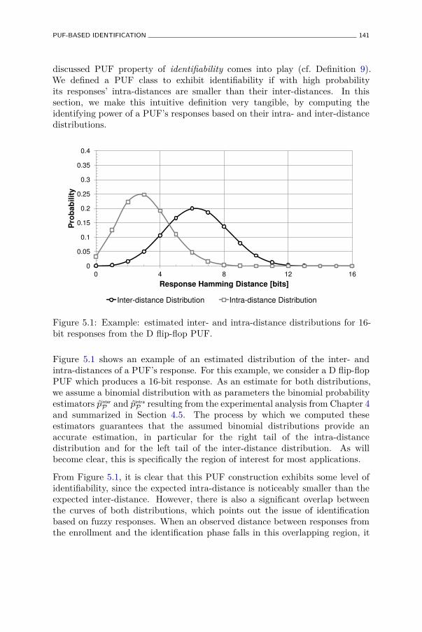
PUF-BASED IDENTIFICATION 141
discussed PUF property of identifiability comes into play (cf. Definition 9).We defined a PUF class to exhibit identifiability if with high probabilityits responses’ intra-distances are smaller than their inter-distances. In thissection, we make this intuitive definition very tangible, by computing theidentifying power of a PUF’s responses based on their intra- and inter-distancedistributions.
0
0.05
0.1
0.15
0.2
0.25
0.3
0.35
0.4
0 4 8 12 16
Pro
bab
ilit
y
Response Hamming Distance [bits]
Inter-distance Distribution Intra-distance Distribution
Figure 5.1: Example: estimated inter- and intra-distance distributions for 16-bit responses from the D flip-flop PUF.
Figure 5.1 shows an example of an estimated distribution of the inter- andintra-distances of a PUF’s response. For this example, we consider a D flip-flopPUF which produces a 16-bit response. As an estimate for both distributions,we assume a binomial distribution with as parameters the binomial probabilityestimators p̂inter
P and p̂intra
P resulting from the experimental analysis from Chapter 4and summarized in Section 4.5. The process by which we computed theseestimators guarantees that the assumed binomial distributions provide anaccurate estimation, in particular for the right tail of the intra-distancedistribution and for the left tail of the inter-distance distribution. As willbecome clear, this is specifically the region of interest for most applications.
From Figure 5.1, it is clear that this PUF construction exhibits some level ofidentifiability, since the expected intra-distance is noticeably smaller than theexpected inter-distance. However, there is also a significant overlap betweenthe curves of both distributions, which points out the issue of identificationbased on fuzzy responses. When an observed distance between responses fromthe enrollment and the identification phase falls in this overlapping region, it
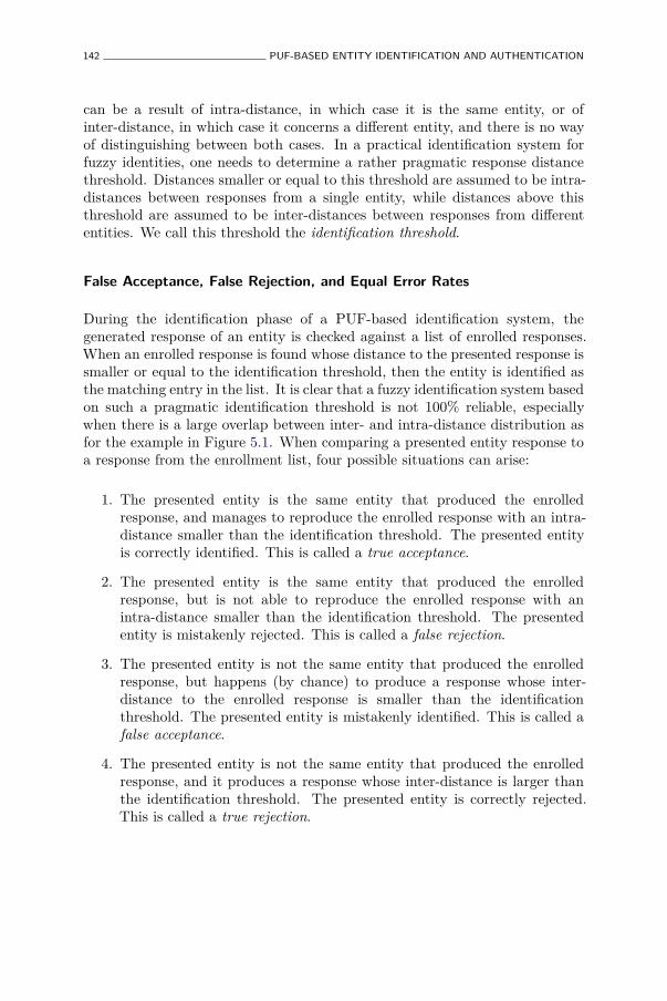
142 PUF-BASED ENTITY IDENTIFICATION AND AUTHENTICATION
can be a result of intra-distance, in which case it is the same entity, or ofinter-distance, in which case it concerns a different entity, and there is no wayof distinguishing between both cases. In a practical identification system forfuzzy identities, one needs to determine a rather pragmatic response distancethreshold. Distances smaller or equal to this threshold are assumed to be intra-distances between responses from a single entity, while distances above thisthreshold are assumed to be inter-distances between responses from differententities. We call this threshold the identification threshold.
False Acceptance, False Rejection, and Equal Error Rates
During the identification phase of a PUF-based identification system, thegenerated response of an entity is checked against a list of enrolled responses.When an enrolled response is found whose distance to the presented response issmaller or equal to the identification threshold, then the entity is identified asthe matching entry in the list. It is clear that a fuzzy identification system basedon such a pragmatic identification threshold is not 100% reliable, especiallywhen there is a large overlap between inter- and intra-distance distribution asfor the example in Figure 5.1. When comparing a presented entity response toa response from the enrollment list, four possible situations can arise:
1. The presented entity is the same entity that produced the enrolledresponse, and manages to reproduce the enrolled response with an intra-distance smaller than the identification threshold. The presented entityis correctly identified. This is called a true acceptance.
2. The presented entity is the same entity that produced the enrolledresponse, but is not able to reproduce the enrolled response with anintra-distance smaller than the identification threshold. The presentedentity is mistakenly rejected. This is called a false rejection.
3. The presented entity is not the same entity that produced the enrolledresponse, but happens (by chance) to produce a response whose inter-distance to the enrolled response is smaller than the identificationthreshold. The presented entity is mistakenly identified. This is called afalse acceptance.
4. The presented entity is not the same entity that produced the enrolledresponse, and it produces a response whose inter-distance is larger thanthe identification threshold. The presented entity is correctly rejected.This is called a true rejection.
PUF-BASED IDENTIFICATION 143
It is clear that false rejections and false acceptances are both undesirable fora practical identification system. The probability that a random identificationattempt results in one of these cases is respectively expressed as the falserejection rate or FRR, and as the false acceptance rate or FAR of the system.FAR expresses the security of an identification system, since a low FAR meansthat there is little risk of misidentification which could lead to security issues.FRR on the other hand expresses the robustness or usability of a system, as itexpresses the risk of wrongfully rejecting legitimate entities, which would bevery impractical. For a usable identification system, both FAR and FRR needto be as small as possible, but it is evident that they cannot be both minimizedat the same time. As is often the case, an acceptable trade-off between securityand usability needs to be made.
For a given identification system, FAR and FRR depend on the choice forthe identification threshold value which we denote as tid. A high thresholdminimizes the risk of a false rejection but increases the likelihood of falseacceptances, and vice versa for a low threshold. When the distributions ofthe inter- and intra-distances of the considered PUF are known, the respectiverelations between FAR, FRR and tid can be computed:
• FAR is the probability that the inter-distance is smaller than or equal totid. This is equivalent to the evaluation of the cumulative distributionfunction of the inter-distance at tid.
• FRR is the probability that the intra-distance is larger than tid. Thisis equivalent to the complement of the evaluation of the cumulativedistribution function of the intra-distance at tid.
For the example presented in Figure 5.1, we have assumed a binomialdistribution for both inter- and intra-distances, hence FAR and FRR become:
FAR(tid) = Fbino(tid; 16, p̂inter
P ),
FRR(tid) = 1− Fbino(tid; 16, p̂intra
P ),
with Fbino(t; n, p) the cumulative binomial distribution function with parame-ters n and p evaluated in t, and p̂inter
P and p̂intra
P the binomial estimators for theD flip-flop PUF taken from Table 4.10. The resulting FAR and FRR for everyidentification threshold value between 0 and 16 are plotted in Figure 5.2a. Fromthis figure it is clear that there is a threshold, and a corresponding error rate,where the plots of FAR and FRR intersect. We call this the equal error thresholdtEER and the corresponding error rate the equal error rate or EER. For discrete
144 PUF-BASED ENTITY IDENTIFICATION AND AUTHENTICATION
0.001
0.01
0.1
1
0 4 8 12 16
Err
or
Ra
te
Identification Threshold
FAR FRR
Equal Error Rate
Equal E
rror
Thre
shold
(a) FAR and FRR plots.
-4
-3.5
-3
-2.5
-2
-1.5
-1
-0.5
0
-4 -3.5 -3 -2.5 -2 -1.5 -1 -0.5 0
log
10(F
RR
)
log10(FAR)
ROC Equal Error Line
Equal Error Rate (ERR)
(b) ROC curve plot.
Figure 5.2: Example: identification metrics for a threshold identification systembased on the PUF described by Figure 5.1.
distributions, FAR and FRR will never be exactly equal for a discrete threshold,and in that case tEER and EER are defined as:
tEER
△
= argmint{max{FAR(t), FRR(t)}},
and
EER△
= max{FAR(tEER), FRR(tEER)}.
The equal error rate is also indicated in Figure 5.2a.
When designing a PUF-based identification system, the FAR and FRR plotsas shown in Figure 5.2a can be used to find a suitable trade-off meeting theapplication requirements. This can, but does not need to be the EER, e.g. insome applications more care is given to security than to usability, or vice versa.A more convenient way for assessing the FRR-vs-FAR trade-off is the plot ofFRR as a function of FAR as shown in Figure 5.2b. Such a plot is also calledthe receiver-operating characteristic or ROC plot of the system. In a ROC plot,the EER is found as the intersection with the identity function which we havelabelled the equal error line in Figure 5.2b. ROC curves completely summarizethe identification performance of an identification system and are particularlyuseful for comparing the performance of different systems. A more condensedperformance qualifier of a particular identification system is given by its EER
value.
PUF-BASED IDENTIFICATION 145
5.2.3 Identification Performance for Different Intrinsic PUFs
In Section 5.2.2 we presented a toy example of a 16-bit D flip-flop PUFidentification system and used it to introduce the different performance metricsof fuzzy identification systems. Now, we will use these introduced metrics toobjectively compare the identification performance of the different intrinsicPUFs which were experimentally studied in Chapter 4. As in Section 5.2.2, wewill assume a binomial distribution for both the inter- and intra-distances ofthese intrinsic PUFs and use the binomial probability estimators as summarizedin Table 4.10. This assumption is justified by the fact that these estimatorswhere derived to accurately describe the critical region of both distributions,i.e. the part where both probability mass functions overlap.
We will first compare the identification performance of all considered PUFsfor a fixed length response. Afterwards, we compare the required parametersof the different PUFs in order to obtain the same identification performance.Ultimately, we combine these obtained parameters with each PUF’s areaestimation to generate an objective as possible comparison of identificationperformance versus silicon area use for each of the intrinsic PUF constructions.
Comparison of ROC Curves for 64-bit Identification with Different PUFs
We consider an identification system based on 64-bit PUF responses and applythe methods introduced in Section 5.2.2 to derive the ROC curves for all eightconsidered intrinsic PUFs, based on their parameters from Table 4.10. All eightROC curves are plotted on the same graph in Figure 5.3.
When reading a ROC curve, it is important to know that the more onemoves to the left (up) on a curve, the more secure an identification systembecomes, i.e. the less likely that a misidentification will happen. On theother hand, moving down (to the right) on a ROC curve gives more robustsystems, i.e. systems which are less likely to result in an unjustified rejection.In this respect, the closer to the lower left corner a particular ROC curve issituated, the better its overall identification performance and the easier to makea meaningful security-usability trade-off.
Analyzing the ROC curves from Figure 5.3, it is clear that an identificationsystem based on 64-bit responses from the ring oscillator PUF with pairwisecomparison greatly outperforms all the other PUFs and is the only PUFwhich obtains an EER ≤ 10−6. Looking at Table 4.10, the high identificationperformance of this ring oscillator PUF is caused by a combination of havingnearly the highest inter-distance parameter (second to the 2-XOR arbiter PUF)and by far the best intra-distance parameter. The ROC curves of the SRAM
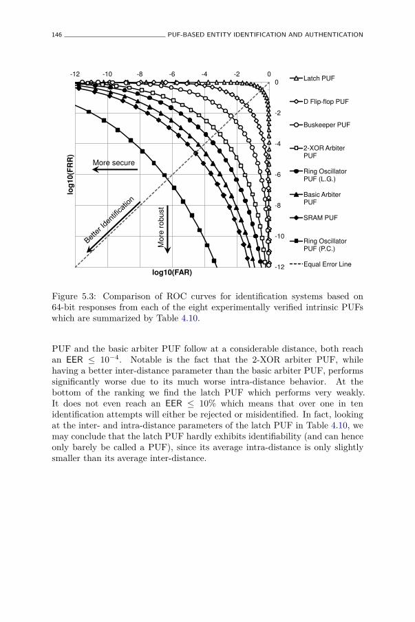
146 PUF-BASED ENTITY IDENTIFICATION AND AUTHENTICATION
-12
-10
-8
-6
-4
-2
0
-12 -10 -8 -6 -4 -2 0 lo
g10(F
RR
)
log10(FAR)
Latch PUF
D Flip-flop PUF
Buskeeper PUF
2-XOR Arbiter PUF
Ring Oscillator PUF (L.G.)
Basic Arbiter PUF
SRAM PUF
Ring Oscillator PUF (P.C.)
Equal Error Line
More secure M
ore
robust
Figure 5.3: Comparison of ROC curves for identification systems based on64-bit responses from each of the eight experimentally verified intrinsic PUFswhich are summarized by Table 4.10.
PUF and the basic arbiter PUF follow at a considerable distance, both reachan EER ≤ 10−4. Notable is the fact that the 2-XOR arbiter PUF, whilehaving a better inter-distance parameter than the basic arbiter PUF, performssignificantly worse due to its much worse intra-distance behavior. At thebottom of the ranking we find the latch PUF which performs very weakly.It does not even reach an EER ≤ 10% which means that over one in tenidentification attempts will either be rejected or misidentified. In fact, lookingat the inter- and intra-distance parameters of the latch PUF in Table 4.10, wemay conclude that the latch PUF hardly exhibits identifiability (and can henceonly barely be called a PUF), since its average intra-distance is only slightlysmaller than its average inter-distance.
PUF-BASED IDENTIFICATION 147
Comparison of PUF Parameters and Areas for Practical IdentificationRequirements
The required identification performance of an identification system is deter-mined by its application, but for most practical applications a FAR and FRR
both ≤ 10−6, and hence an EER ≤ 10−6, is minimally desired. For manyapplications, EER even needs to be considerably smaller, e.g. EER ≤ 10−9 oreven EER ≤ 10−12 can be required for critical systems. Aiming for a lowerEER also provides more freedom in selecting an optimal FAR-vs-FRR trade-off. The results from Figure 5.3 show that with a 64-bit PUF response, onlythe pairwise-comparison ring oscillator PUF achieves EER ≤ 10−6. In orderto obtain a better identification performance based on the same PUF, longerresponses need to be considered as identifiers. In the following we examinewhich response lengths, denoted as nid, are needed for every considered PUFto reach an identification performance of respectively EER ≤ 10−6, EER ≤ 10−9
and EER ≤ 10−12.
To ultimately obtain an objective comparison of the identification performanceof the different considered PUFs, we also need to take their silicon area efficiencyinto account. After determining the minimal required response length nid toachieve a certain identification performance, we estimate the required siliconarea a PUF construction needs to occupy to produce a response of that length.These area estimations are based on the area breakdown of our test chip aspresented in Table 4.1. We use the following approach for scaling the area ofthe different PUFs:
• For the memory-based PUFs, we scale the area completely bitwise,i.e. the estimated silicon area of the entire PUF block as presented inTable 4.1 is divided by the total number of bit cells of the consideredPUF implemented on the test chip and multiplied by nid. This is a veryrough estimation as it does not take fixed overhead into account, and itassumes bit cells can be instantiated one by one. Especially for the SRAMPUF this is not very accurate since it neglects the overhead of the addressdecoder, sense amplifiers, readout circuitry, etc. Moreover typical SRAMarray implementations come in multiples of kilobytes, not bits. However,given the limited knowledge we have about the implemented PUF areas,this is the best estimate we can give. For the other memory-based PUFsthe estimate is better since they can be instantiated on a bit by bit basis.For the D flip-flop PUF with the chained read-out implementation, thisestimation is even fairly accurate.
• For both arbiter-based PUFs, the silicon area is relatively independent ofthe required number of response bits, since a single 64-bit arbiter PUF
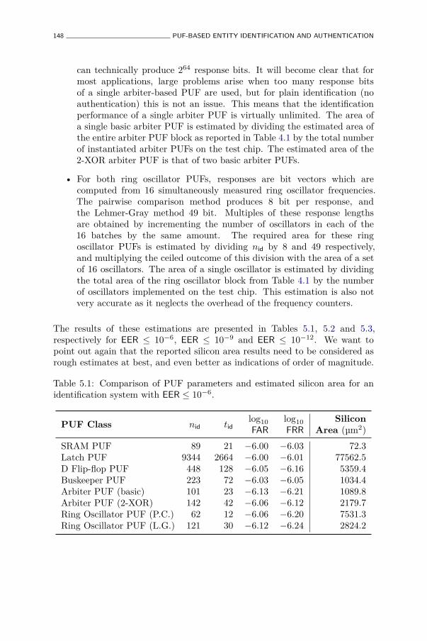
148 PUF-BASED ENTITY IDENTIFICATION AND AUTHENTICATION
can technically produce 264 response bits. It will become clear that formost applications, large problems arise when too many response bitsof a single arbiter-based PUF are used, but for plain identification (noauthentication) this is not an issue. This means that the identificationperformance of a single arbiter PUF is virtually unlimited. The area ofa single basic arbiter PUF is estimated by dividing the estimated area ofthe entire arbiter PUF block as reported in Table 4.1 by the total numberof instantiated arbiter PUFs on the test chip. The estimated area of the2-XOR arbiter PUF is that of two basic arbiter PUFs.
• For both ring oscillator PUFs, responses are bit vectors which arecomputed from 16 simultaneously measured ring oscillator frequencies.The pairwise comparison method produces 8 bit per response, andthe Lehmer-Gray method 49 bit. Multiples of these response lengthsare obtained by incrementing the number of oscillators in each of the16 batches by the same amount. The required area for these ringoscillator PUFs is estimated by dividing nid by 8 and 49 respectively,and multiplying the ceiled outcome of this division with the area of a setof 16 oscillators. The area of a single oscillator is estimated by dividingthe total area of the ring oscillator block from Table 4.1 by the numberof oscillators implemented on the test chip. This estimation is also notvery accurate as it neglects the overhead of the frequency counters.
The results of these estimations are presented in Tables 5.1, 5.2 and 5.3,respectively for EER ≤ 10−6, EER ≤ 10−9 and EER ≤ 10−12. We want topoint out again that the reported silicon area results need to be considered asrough estimates at best, and even better as indications of order of magnitude.
Table 5.1: Comparison of PUF parameters and estimated silicon area for anidentification system with EER ≤ 10−6.
PUF Class nid tidlog10
FAR
log10
FRR
SiliconArea (µm2)
SRAM PUF 89 21 −6.00 −6.03 72.3Latch PUF 9344 2664 −6.00 −6.01 77562.5D Flip-flop PUF 448 128 −6.05 −6.16 5359.4Buskeeper PUF 223 72 −6.03 −6.05 1034.4Arbiter PUF (basic) 101 23 −6.13 −6.21 1089.8Arbiter PUF (2-XOR) 142 42 −6.06 −6.12 2179.7Ring Oscillator PUF (P.C.) 62 12 −6.06 −6.20 7531.3Ring Oscillator PUF (L.G.) 121 30 −6.12 −6.24 2824.2
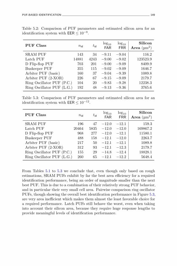
PUF-BASED IDENTIFICATION 149
Table 5.2: Comparison of PUF parameters and estimated silicon area for anidentification system with EER ≤ 10−9.
PUF Class nid tidlog10
FAR
log10
FRR
SiliconArea (µm2)
SRAM PUF 143 34 −9.11 −9.04 116.2Latch PUF 14881 4243 −9.00 −9.02 123523.9D Flip-flop PUF 703 201 −9.00 −9.09 8409.9Buskeeper PUF 355 115 −9.02 −9.09 1646.7Arbiter PUF (basic) 160 37 −9.04 −9.39 1089.8Arbiter PUF (2-XOR) 226 67 −9.15 −9.09 2179.7Ring Oscillator PUF (P.C.) 104 20 −9.83 −9.28 12238.3Ring Oscillator PUF (L.G.) 192 48 −9.13 −9.36 3765.6
Table 5.3: Comparison of PUF parameters and estimated silicon area for anidentification system with EER ≤ 10−12.
PUF Class nid tidlog10
FAR
log10
FRR
SiliconArea (µm2)
SRAM PUF 196 47 −12.0 −12.1 159.3Latch PUF 20464 5835 −12.0 −12.0 169867.2D Flip-flop PUF 968 277 −12.0 −12.1 11580.1Buskeeper PUF 488 158 −12.1 −12.0 2263.7Arbiter PUF (basic) 217 50 −12.1 −12.1 1089.8Arbiter PUF (2-XOR) 312 93 −12.1 −12.3 2179.7Ring Oscillator PUF (P.C.) 155 29 −14.8 −12.4 18828.1Ring Oscillator PUF (L.G.) 260 65 −12.1 −12.2 5648.4
From Tables 5.1 to 5.3 we conclude that, even though only based on roughestimations, SRAM PUFs exhibit by far the best area efficiency for a requiredidentification performance, being an order of magnitude smaller than the nextbest PUF. This is due to a combination of their relatively strong PUF behavior,and in particular their very small cell area. Pairwise comparison ring oscillatorPUFs, though showing the overall best identification performance in Figure 5.3,are very area inefficient which makes them almost the least favorable choice fora required performance. Latch PUFs still behave the worst, even when takinginto account their silicon area, because they require huge response lengths toprovide meaningful levels of identification performance.
150 PUF-BASED ENTITY IDENTIFICATION AND AUTHENTICATION
5.3 PUF-based Entity Authentication
5.3.1 Background: PUF Challenge-Response Authentication
When an entity wants to authenticate itself to an another party, typically calledthe verifier, it needs to provide, besides a plain identification, also corroborativeevidence of its presented identity, i.e. evidence which could only have beencreated by that particular entity. An entity typically achieves this goal byproving to the verifier that it knows, possesses or contains a particular secretwhich only that entity can know, have or contain. In addition, the entityalso needs to convince the verifier that it was actively, i.e. at the time ofauthenticating, involved in creating that evidence. In this section, we discusshow an entity can authenticate itself based on the possession/containmentof a unique PUF instance. An authentication scenario is considered with acentralized verifier and entities which authenticate to the central verifier, notto each other.
There are two main approaches towards developing a PUF-based authenticationsystem. The first approach is to develop an authentication scheme whichdirectly deploys the unique and unpredictable challenge-response behavior ofa particular PUF instance. The second approach consists of deriving a robustand secure cryptographic key from a PUF response and use this key in anexisting classic key-based cryptographic authentication protocol. PUF-basedkey generation is discussed in detail in Chapter 6. In this section, we focus onthe challenge-response approach which is usually more efficient, since it doesnot require an additional implementation of a key generation algorithm andother keyed cryptographic primitives.
Basic PUF-based Challenge-Response Authentication
The basic PUF-based challenge-response entity authentication scheme, amongothers described by Gassend et al. [47], Ranasinghe et al. [113] and Devadaset al. [36], consists of two phases: enrollment and verification:
1. Before deployment, every entity goes through enrollment by the verifier.During the enrollment phase, the verifier records the identity3 ID of everyentity, and collects a significant subset of challenge-response pairs of everyentity’s PUF, for randomly generated challenges. The collected challenge-
3Identification can happen both with assigned or inherent identifiers, as discussed in detailin Section 5.2. For simplicity, but without loss of generality, we assume an entity identifieswith an assigned identifier ID in this section.
PUF-BASED ENTITY AUTHENTICATION 151
response pairs are stored in the verifier’s database DB, indexed by theentity’s ID.
2. During the verification phase, an entity identifies to the verifier bysending its ID. The verifier looks up the ID in its DB, and selects arandom PUF challenge-response pair stored with that ID. The PUFchallenge is sent to the entity, the entity evaluates its PUF with thatchallenge and replies with the obtained response. The verifier checkswhether the replied response is close to the response it has in itsdatabase, i.e. both responses differ no more than some predeterminedauthentication threshold tauth. If this check succeeds, the entity isauthenticated, otherwise the authentication is rejected. The usedchallenge-response pair is removed from DB.
The correctness of this authentication scheme is ensured by the fact thatPUF responses are reproducible over time, up to a small intra-distance. Iftauth is set large enough such that with high probability the intra-distance issmaller, the authentication of a legitimate entity succeeds. For the securityof the authentication, the verifier relies on the fact that PUFs are unique andunclonable, and only the genuine PUF can with high probability reproduce aclose response to a previously unobserved and random challenge.
Drawbacks of the Basic Protocol
Unfortunately, while strikingly simple and low-cost, this basic protocol exhibitsa number of major shortcomings and drawbacks:
• It is clear that challenge-response pairs cannot be reused in order to avoidreplay attacks, and a used pair is therefore removed from DB after theprotocol finishes. This entails that the verifier needs to store a largenumber of pairs for each entity to make sure that every entity can beauthenticated a reasonable number of times. Maintaining such a largedatabase is a significant effort. Moreover, it requires that the consideredPUF construction has a large challenge set to begin with, which alreadyrules out a significant number of proposed PUF constructions.
• When the stored challenge-response pairs in DB of an entity run out, theentity can no longer be authenticated by the verifier. To make furtherauthentications possible, the entity needs to be re-enrolled. This requireseither a physical withdrawal of the entity from the field to undergo re-enrollment at the verifier’s secured premises, or an elaborate and costlyextension of the basic protocol to make remote re-enrollment possible.
152 PUF-BASED ENTITY IDENTIFICATION AND AUTHENTICATION
• The basic protocol only provides authentication of an entity to theverifier, no mutual authentication can be supported without significantlyextending the basic protocol.
• The basic protocol is only secure for truly unclonable PUFs (cf. Defi-nition 13), i.e. PUFs which are also mathematically unclonable. PUFswhich can be cloned in a mathematical sense (and which are hencestill considered PUFs according to Definition 16), do not offer secureauthentication, since the basic protocol can no longer distinguish betweenthe real entity with the physical PUF, and an impersonator with amathematical clone of that PUF. From Table 3.1, it is clear thatonly the optical PUF presents convincing evidence to be consideredmathematically unclonable, which means the basic scheme is currentlyonly secure when an optical PUF is deployed.4
Improvements and extensions of this basic protocol have been proposed,e.g. by Bolotnyy and Robins [15] and Kulseng et al. [76], to relax the strictrequirements on the PUF construction and the database. However, theseproposals do not completely succeed to overcome the shortcomings of thebasic protocol, or they introduce new restrictions. Some of these proposalsare moreover shown to be insecure, e.g. Kardas et al. [68] point out significantsecurity weaknesses of the proposal by Kulseng et al. [76].
Motivation
The simplicity of the basic PUF-based challenge-response authenticationprotocol is very appealing, especially when entities are heavily constrainedsilicon devices such as RFID tags which cannot dedicate many resourcesto implementations of cryptographic building blocks. A possibly significantimprovement in the resource-security trade-off of such devices is possible,if they can be authenticated only based on an efficient embedded intrinsicPUF implementation. Unfortunately, no intrinsic PUF candidates currentlyexist which meet the very strong requirement of mathematical unclonabilityneeded to make the basic challenge-response authentication protocol secure.Constructing a practical intrinsic PUF for which strong guarantees of math-ematical unclonability can be provided is currently considered an importantopen problem in the study of PUFs and their constructions.
Instead of attempting to tackle this difficult open problem, we will proposean alternative PUF-based authentication protocol in this section, which has
4Intrinsic PUF constructions have been proposed which are candidates for mathematicalunclonability, but currently they lack convincing argumentation to be classified as such.

PUF-BASED ENTITY AUTHENTICATION 153
considerably relaxed requirements for the PUF which is used, and whichmoreover provides mutual authentication. We need a little more complexitythan the basic protocol (less is virtually impossible), but aim to keep it at aminimum, especially on the entity’s side which we consider to be a resource-constrained device like an RFID tag.
5.3.2 A PUF-based Mutual Authentication Scheme
Rationale
The premise on which we base our proposed protocol is that the amount ofunpredictability in the challenge-response behavior of an intrinsic PUF instanceis strictly limited, and increasing it comes at a high relative implementation cost.Note that this is the case for all currently known intrinsic PUF constructions. Itis therefore not recommendable to publicly disclose challenge-response pairs inthe protocol’s communications, as the basic protocol does, since every disclosedpair significantly reduces the remaining unpredictability of the PUF’s behavior.This quickly result in a situation where the PUF-carrying entity can no longerbe securely authenticated.
In classic cryptographic challenge-response authentication protocols based onsymmetric-key techniques (cf. [102, Section 10.3.2]), an entity does also notauthenticate itself by disclosing its secret key, since this would render theauthentication insecure after one protocol run. Instead, an entity only provesits knowledge of the secret key by showing that it can calculate encryptions orkeyed one-way function evaluations of randomly applied challenges, withoutrevealing any information about the key’s value. We follow the same lineof thought in our protocol: an entity demonstrates its possession of a PUFinstance by demonstrating that it can calculate a function evaluation whichtakes an unpredictable PUF response as input, without fully disclosing theunpredictable nature of the response in the result of this evaluation.
An obvious choice for such a concealing function would be a one-way function,e.g. instantiated as a cryptographic hash function, since a one-way functionevaluation of a PUF response does not disclose any significant informationabout the response value. The verifier could then calculate the same one-wayfunction evaluation on the response in its database and check if this matchesthe entity’s response. However, this runs into the problem of the non-perfectreproducibility of the PUF’s responses. Whereas the entity’s PUF responsevalue will typically be close to the enrolled PUF response value in the verifier’sdatabase, the one-way function evaluations of both are completely independentand can not be meaningfully matched to each other. This is also a (in this case
154 PUF-BASED ENTITY IDENTIFICATION AND AUTHENTICATION
negative) consequence of the one-way function destroying any predictabilitybetween input and output.
To overcome this issue, we need to deploy some form of error-correction in theprotocol to make sure that both parties, the entity and the verifier, computethe one-way function on exactly the same PUF response value. In order tobe able to do this, the entity and the verifier need to publicly exchange anamount of information about the PUF response. This is typically called sideinformation, or also helper data in the context of PUF-based key generationalgorithms (cf. Chapter 6). We show that it is possible for some intrinsicPUFs to find a good balance between the amount of side information oneneeds to disclose, and the amount of unpredictability that is left in the PUFresponse after observing the side information, to obtain a reliable but secureauthentication. Note that at no point in our proposed protocol do we derivea cryptographically secure key or do we use a keyed cryptographic primitive.Moreover, while being related to the key-generation algorithms discussed inChapter 6, the used error-correction technique in this protocol is considerablyless computationally expensive, especially on the entity’s side.
Background. The mutual authentication scheme as described in [150], ofwhich a slightly adapted version is presented in this section, is the shared resultof numerous fruitful discussions and an intense research collaboration betweenthe author and Anthony van Herrewege, Roel Peeters and professor IngridVerbauwhede (all University of Leuven), and Christian Wachsmann, professorStefan Katzenbeisser and professor Ahmad-Reza Sadeghi (all TechnischeUniversität Darmstadt). The key idea and development of the “reverse” securesketch is due to the author.
“Reversed” Secure Sketching based on Linear Block Code Syndromes
The error-correction technique we deploy in the protocol is a practical versionof the syndrome construction of a secure sketch, as described by Dodis et al.[39] [38], with the sketching procedure executed by the entity, and the recoveryprocedure executed by the verifier. Note that this execution order implies thatthe entity generates the “correct” version of the PUF response and the verifierneeds to correct his stored response value to match that of the entity. This isthe opposite way as secure sketching is typically deployed, e.g. in PUF-basedkey generation, with the verifier storing a single fixed secret key and helperdata string and requiring the entity to correct its noisy response, with the helpof the helper data, to generate the same key as the verifier. For this reason, we
PUF-BASED ENTITY AUTHENTICATION 155
call this a reverse secure sketch. The use of such a reverse secure sketch hassome peculiar and interesting side effects:
• Since the entity’s PUF response is only non-perfectly reproducible, theactual response value on which the authentication is based will possiblybe different for each run of the protocol. This means the exchanged sideinformation will also be different for each run. Since the side informationpartially discloses the response value, we need to consider this whenshowing the security of the protocol, i.e. we do not want multiple runs ofthe protocol to disclose the full response value. We are able to prove thateven after an indeterminate number of protocol runs, with each a possiblydifferent side information string based on a different noisy response value,the remaining unpredictability of the PUF response remains high.
• Since the sketching procedure of a secure sketch is typically much lesscomputationally complex than the recovery procedure, it can be efficientlyimplemented by each entity using a small amount of resources. Thecentral verifier is assumed to be less resource-constrained and easilycapable of implementing the recovery procedure.
Secure sketch constructions based on linear block codes are explained in detailin Section 6.2.1. We refer to that section for more background on the operationof the syndrome construction used in our protocol. Summarized very briefly:
• The sketching procedure of the syndrome construction, executed by anentity, consists of a binary matrix multiplication of the entity’s PUFresponse evaluation with the parity-check matrix of a linear block code,resulting in the side information for the protocol run: wi := y′i ·H
T.
• The recovery procedure, as executed by the verifier, consists of threesteps: i) a syndrome is calculated based on the received side informationand the stored PUF response value from the verifier’s database: si :=wi ⊕ yi ·H
T ≡ ei ·HT, with ei = (y′i ⊕ yi). ii) the syndrome is decoded
to an error string: Decode(si) → e′i, with e′i = ei if HD (yi; y′i) ≤ tauth,with tauth the bit error correction capacity of the underlying code. iii) theresponse reconstruction: y′′i := yi⊕ e′i, with y′′i = y′i if HD (yi; y′i) ≤ tauth.
The Mutual Authentication Protocol
The execution flow of our proposed PUF-based mutual authentication protocolis shown in Figure 5.4. This is a modified version of the protocol we haveintroduced in [150], the main difference being the reversal of the authentication
156 PUF-BASED ENTITY IDENTIFICATION AND AUTHENTICATION
checks such that the an entity will only authenticate to a legitimate verifier. Weexplain the different operations in more detail:
• Each entity (Enti) is assigned a unique identifier ID and equipped witha unique PUF instance pufi. We only require a single challenge-responsepair per PUF, hence we do not explicitly write the challenge: pufi → y′i.
• Prior to deployment, all entities are enrolled by the verifier (Ver), whichkeeps a database DB of a single response evaluation yi of every entity’sPUF, indexed by the entity’s ID. PUF responses can only be enrolledonce. This is enforced by physically blocking or even destroying theentity’s enrollment interface which directly outputs the PUF response.
• Each entity implements the sketching procedure of the secure sketch,which is simply a binary matrix multiplication with a parity-check matrixHT of a linear block code. Due to the special structure of these matricesfor many block codes, this multiplication can often be very efficientlyimplemented in digital hardware.
• The verifier implements the recovery procedure of the secure sketch:Recover(yi, wi). This procedure contains an error-correction decodingalgorithm which typically requires a considerable computational effort.
• Each entity, as well as the verifier, implements a cryptographically securehash function: Hash(.).
• Each entity, as well as the verifier, has access to a cryptographically securerandom bit generator which they use to generate random nonces used inthe protocol: ri ← {0, 1}ℓ. The nonces are used to introduce freshnessin the protocol’s messages in order to avoid replay attacks. Later wepropose a possible optimization in which entities do not need to producea nonce and hence do not require a random bit generator.
Correctness
The correctness of the protocol is guaranteed by the error-correction capabilityof the underlying linear block code of the secure sketch. If, with high probability,the intra-distance between the PUF response produced by a legitimate entityduring a protocol run and the response in the legitimate verifier’s database, issmaller or equal to the error-correcting capacity tauth of the underlying blockcode, then the verifier is able to recover the same response value producedby the entity. In that case, both hash value checks will succeed and mutualauthentication is accomplished. Based on the intra-distance distribution of
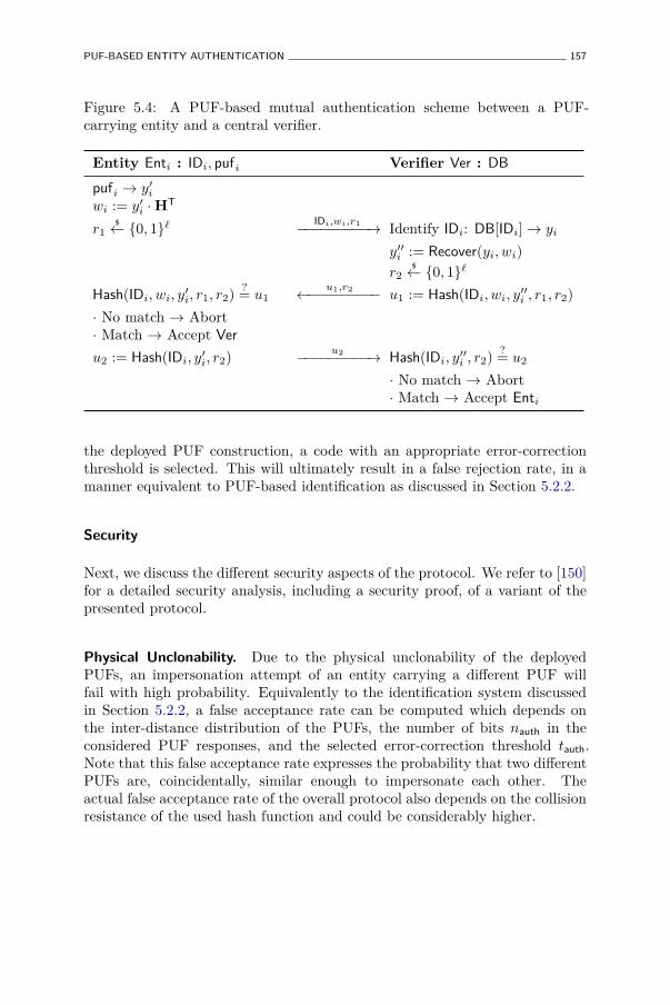
PUF-BASED ENTITY AUTHENTICATION 157
Figure 5.4: A PUF-based mutual authentication scheme between a PUF-carrying entity and a central verifier.
Entity Enti : IDi, pufi Verifier Ver : DB
pufi → y′iwi := y′i ·H
T
r1$← {0, 1}ℓ IDi,wi,r1
−−−−−−−−−→ Identify IDi: DB[IDi]→ yi
y′′i := Recover(yi, wi)
r2$← {0, 1}ℓ
Hash(IDi, wi, y′i, r1, r2)?= u1
u1,r2←−−−−−−−−− u1 := Hash(IDi, wi, y′′i , r1, r2)
· No match → Abort· Match → Accept Ver
u2 := Hash(IDi, y′i, r2)u2−−−−−−−−−→ Hash(IDi, y′′i , r2)
?= u2
· No match → Abort· Match → Accept Enti
the deployed PUF construction, a code with an appropriate error-correctionthreshold is selected. This will ultimately result in a false rejection rate, in amanner equivalent to PUF-based identification as discussed in Section 5.2.2.
Security
Next, we discuss the different security aspects of the protocol. We refer to [150]for a detailed security analysis, including a security proof, of a variant of thepresented protocol.
Physical Unclonability. Due to the physical unclonability of the deployedPUFs, an impersonation attempt of an entity carrying a different PUF willfail with high probability. Equivalently to the identification system discussedin Section 5.2.2, a false acceptance rate can be computed which depends onthe inter-distance distribution of the PUFs, the number of bits nauth in theconsidered PUF responses, and the selected error-correction threshold tauth.Note that this false acceptance rate expresses the probability that two differentPUFs are, coincidentally, similar enough to impersonate each other. Theactual false acceptance rate of the overall protocol also depends on the collisionresistance of the used hash function and could be considerably higher.
158 PUF-BASED ENTITY IDENTIFICATION AND AUTHENTICATION
Replay Attacks. The random nonces r1 and r2 respectively generated by theentity and the verifier preclude replay attacks from both sides, by introducingfreshness in the protocol communications. An adversary trying to replayprotocol messages in order to impersonate the verifier will fail since the entitywill present a different nonce value and the adversary cannot recompute thehash evaluation over this new nonce since he doesn’t know the PUF response.The same holds for an adversary trying to impersonate an entity by replayingearlier recorded messages from a successful entity authentication. Under certainconditions, the nonce generated by the entity can even be omitted. This is thecase if the expected intra-distance on the entity’s PUF response is large enoughsuch that it is highly unlikely that exactly the same response value will everbe reproduced. In that case, the freshness of the protocol is guaranteed bythe noise on the entity response, given that it is large enough. A practicaladvantage of this variant is that entities do not need access to a random bitgenerator any longer, which reduces the resource requirements of the protocol.
Response Unpredictability. We still need to assess the unpredictability ofresponses, given that the adversary can observe multiple side informationstrings from many successful authentication attempts of an entity. We firstconsider the unpredictability of a response after observing one side informationstring. After observing a protocol run, an adversary can launch an offline attackon the unknown response value y′i based on the observed quartet (IDi, r1, wi, u1),
by guessing a response value y∗i and checking whether Hash(IDi, wi, y∗i , r1)?= u1.
Note that, by observing the side information, an adversary gains quite someinformation about the response value y′i, since every bit of wi is a linearcombination of bits from y′i, which helps him in the guessing attack. Weexpress the remaining unpredictability of the response as its conditionalentropy when conditioned on the side information. It is rather trivial toshow that H(Y ′i |Wi) ≥ H(Y ′i )− |Wi|. This means that to ensure there is anyunpredictability left, the length of the side information needs to be smallerthan the response’s entropy. Now we show that the unpredictability of the PUFresponse remains this high even after observing many side information stringscomputed over different (possibly noisy) evaluations of the same response, byproving the following lemma:5
Lemma 1. If ∀j : Y ′i and Dintraj are pairwise independently distributed, then:
H(Y ′i |f(Y ′i ), f(Y ′i ⊕Dintra
1 ), f(Y ′i ⊕Dintra
2 ), . . . , f(Y ′i ⊕Dintra
q )) = H(Y ′i |f(Y ′i )),
for any positive integer q and for any linear function f .
5Note that this proof also differs from the security proof given in [150].
PUF-BASED ENTITY AUTHENTICATION 159
Proof.
H(Y ′i |f(Y ′i ), f(Y ′i ⊕Dintra
1 ), f(Y ′i ⊕Dintra
2 ), . . . , f(Y ′i ⊕Dintra
q )),
(f is a linear function),
= H(Y ′i |f(Y ′i ), f(Y ′i )⊕ f(Dintra
1 ), f(Y ′i )⊕ f(Dintra
2 ), . . . , f(Y ′i )⊕ f(Dintra
q )),
= H(Y ′i |f(Y ′i ), f(Dintra
1 ), f(Dintra
2 ), . . . , f(Dintra
q )),
(∀j : Y ′i and Dintra
j are independent),
= H(Y ′i |f(Y ′i )).
The assumption of independence between the distributions of response valuesand intra-distances is very reasonable since they originate from differentphysical processes. This lemma is directly applicable to our situation, sinceevery helper data string is a linear function of a response evaluation. Based ona similar reasoning, one can also show that the remaining min-entropy remainshigh. This is proven in a generalized form by Boyen [19]. The response’sunpredictability as expressed by H(Y ′i |Wi) measures the resistance against anoffline attack, hence it needs to be sufficiently large to offer long-term security.
5.3.3 Authentication Performance of Different Intrinsic PUFs
Proposed Entity Design
We first determine a concrete and realistic design of an entity which is usedto compare the authentication performance of different intrinsic PUFs in theproposed protocol. The main design choice is the selection of the underlyingerror-correcting linear block code of the secure sketch. We refer to Burr [24,Chapter 6] for a detailed introduction to block codes. We propose to use aconcatenation of a simple repetition code followed by a BCH code as introducedby Hocquenghem [56] and Bose and Ray-Chaudhuri [18], which yields an overallsyndrome construction with a relatively high error correction performance. TheBCH code’s parameters are [nBCH, kBCH, tBCH], which means that it has code wordsof length nBCH and dimension kBCH, and up to tBCH bit errors in a single codeword can be corrected. The corresponding parameters of the repetition codeare [nREP, 1, nREP−1
2 ], with nREP odd.
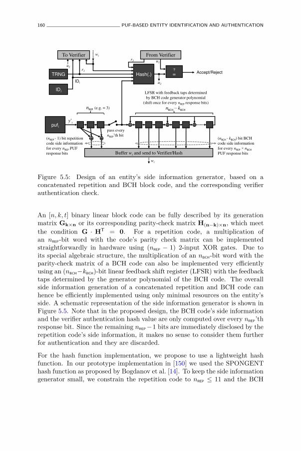
160 PUF-BASED ENTITY IDENTIFICATION AND AUTHENTICATION
pufi
Buffer wi and send to Verifier/Hash
REPnBCHBCH
kn �
iy'
(nREP - 1) bit repetition
code side information
for every nREP PUF
response bits
(nBCH - kBCH) bit BCH
code side information
for every nREP î nBCH
PUF response bits
pass every
nREP¶WK�ELW
LFSR with feedback taps determined
by BCH code generator polynomial
(shift once for every nREP response bits)
(e.g. = 3)
Hash(.)
IDi
wi
r1
IDi
TRNG ?
=
From Verifier u1
Accept/Reject
To Verifier r2
u2
u2
wi
Figure 5.5: Design of an entity’s side information generator, based on aconcatenated repetition and BCH block code, and the corresponding verifierauthentication check.
An [n, k, t] binary linear block code can be fully described by its generationmatrix Gk×n or its corresponding parity-check matrix H(n−k)×n, which meetthe condition G · HT = 0. For a repetition code, a multiplication ofan nREP-bit word with the code’s parity check matrix can be implementedstraightforwardly in hardware using (nREP − 1) 2-input XOR gates. Due toits special algebraic structure, the multiplication of an nBCH-bit word with theparity-check matrix of a BCH code can also be implemented very efficientlyusing an (nBCH−kBCH)-bit linear feedback shift register (LFSR) with the feedbacktaps determined by the generator polynomial of the BCH code. The overallside information generation of a concatenated repetition and BCH code canhence be efficiently implemented using only minimal resources on the entity’sside. A schematic representation of the side information generator is shown inFigure 5.5. Note that in the proposed design, the BCH code’s side informationand the verifier authentication hash value are only computed over every nREP’thresponse bit. Since the remaining nREP−1 bits are immediately disclosed by therepetition code’s side information, it makes no sense to consider them furtherfor authentication and they are discarded.
For the hash function implementation, we propose to use a lightweight hashfunction. In our prototype implementation in [150] we used the SPONGENThash function as proposed by Bogdanov et al. [14]. To keep the side informationgenerator small, we constrain the repetition code to nREP ≤ 11 and the BCH
PUF-BASED ENTITY AUTHENTICATION 161
code to nBCH ≤ 255. We now investigate the implementation parameters ofthis proposed design, within these constraints, when the deployed PUF is oneof the intrinsic PUFs studied in Chapter 4. In particular, we determine therequired code parameters based on the intrinsic PUFs’ statistics summarizedin Table 4.10. Based on these code parameters, the required number of PUFresponse bits, and ultimately the required PUF silicon area to reach a particularauthentication performance can be calculated.
Example of Authentication Performance Calculation
We demonstrate how the authentication performance is calculated for a singlePUF in an exemplary but realistic scenario. Next, we present the results ofthe same calculations for all the studied intrinsic PUFs studied in a number ofpossible scenarios.
As an example, we consider the SRAM PUF, and we aim for an authenticationperformance with EER ≤ 10−9 and an unpredictability of at least 128 bits,i.e. H(Y |W ) ≥ 128. Searching the design space constrained by the proposedentity design above yields the following parameters:
• A [nREP = 3, 1, 1] repetition code and a [nBCH = 223, kBCH = 83, tBCH = 21]BCH code are used. In total, 3× a BCH code length is required.
• These code parameters achieve an overall FRR = 10−9.63 andFAR = 10−104.84.
• The total number of required PUF response bits isnauth = 3× nREP × nBCH = 2007.
• The total number of exchanged side information bits isℓauth = 3× (nREP × nBCH − kBCH) = 1785.
• The remaining entropy is calculated as H(Y |W ) ≥ H(Y )− |W | =nauth × ρ(Y nauth)− ℓauth = 2007× 94.09%− 1758 = 130.4 bits.
Note that these parameters are optimized within the given constraints to yieldto smallest possible number of required PUF bits. For most intrinsic PUFs,the entropy density ρ(Y nauth) is a constant and independent of the number ofconsidered response bits, as shown in Table 4.10. However, for both arbiter-based PUFs, ρ(Y nauth) is a decreasing function of the required number of bitsnauth, of which an upper bound is given by Figure 4.5.
162 PUF-BASED ENTITY IDENTIFICATION AND AUTHENTICATION
Performance Comparison of Different Intrinsic PUFs
Now we apply the same calculation as in this example on all studied intrinsicPUFs for three different authentication performances:
1. A low-cost security scenario with EER ≤ 10−6 and H(Y |W ) ≥ 80.
2. A realistic security scenario with EER ≤ 10−9 and H(Y |W ) ≥ 128.
3. A critical security scenario with EER ≤ 10−12 and H(Y |W ) ≥ 256.
Based on the number of response bits needed, the required silicon area isalso calculated in the same manner (and with the same disclaimers) as inSection 5.2.3. The results are presented in Table 5.4.
From Table 5.4, it is clear that for many studied intrinsic PUFs, no parametersolutions meeting the presented design constraints can be found. This is mostlya result of a too high average intra-distance, a too low entropy density, or acombination of both. Only the SRAM PUF and the pairwise comparison ringoscillator PUF succeed in providing a solution for all three considered scenarios.The SRAM PUF solution offers a better area efficiency than the ring oscillatorPUF by almost two orders of magnitude.
5.4 Conclusion
In Section 5.2 of this chapter, we have successfully demonstrated that aPUF response can be used as a secure and reliable inherent identifier of aPUF-embedding entity. The identification performance, in terms of a falseacceptance, false rejection and equal error rate, scales only with the bit length ofthe PUF response. For the intrinsic PUFs studied in Chapter 4, this ultimatelycomes down to a scaling with the required silicon area needed to implement thePUF. The scaling factor is different for every intrinsic PUF constructions and isdetermined by the characteristics of their inter- and intra-distance distributions.A comparative analysis, as presented in Tables 5.2 up to 5.3, indicates that for agiven silicon area, the SRAM PUF provides the best identification performancein terms of equal error rate. The latch PUF on the other hand exhibits verypoor identification capabilities, which severely undermines its usage as a PUF.
We build upon these identification capabilities of intrinsic PUFs to providesecure entity authentication. In order to obtain a cryptographic level ofauthentication security, we proposed a new authentication protocol betweena central verifier and a deployed entity, shown in Figure 5.4, that utilizes a
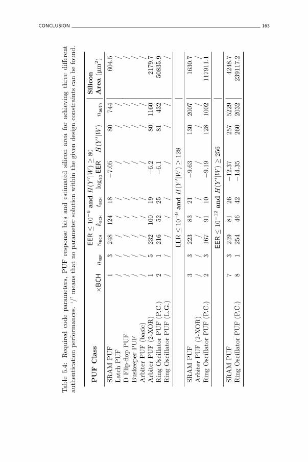
CONCLUSION 163
Tab
le5.
4:R
equi
red
code
para
met
ers,
PU
Fre
spon
sebi
tsan
des
tim
ated
silic
onar
eafo
rac
hiev
ing
thre
edi
ffer
ent
auth
enti
cati
onp
erfo
rman
ces.
‘/’
mea
nsth
atno
para
met
erso
luti
onw
ithi
nth
egi
ven
desi
gnco
nstr
aint
sca
nb
efo
und.
PU
FC
lass
EE
R≤
10−
6an
dH
(Y′ |W
)≥
80S
ilic
on
Are
a(µ
m2)
×B
CH
nR
EP
nB
CH
kB
CH
t BC
Hlo
g 10
EE
RH
(Y′ |W
)n
auth
SRA
MP
UF
13
248
124
18−
7.05
8074
460
4.5
Lat
chP
UF
//
//
//
//
/D
Flip
-flop
PU
F/
//
//
//
//
Bus
keep
erP
UF
//
//
//
//
/A
rbit
erP
UF
(bas
ic)
//
//
//
//
/A
rbit
erP
UF
(2-X
OR
)1
523
210
019
−6.
280
1160
2179
.7R
ing
Osc
illat
orP
UF
(P.C
.)2
121
652
25−
6.1
8143
250
835.
9R
ing
Osc
illat
orP
UF
(L.G
.)/
//
//
//
//
EE
R≤
10−
9an
dH
(Y′ |W
)≥
128
SRA
MP
UF
33
223
8321
−9.
6313
020
0716
30.7
Arb
iter
PU
F(2
-XO
R)
//
//
//
//
/R
ing
Osc
illat
orP
UF
(P.C
.)2
316
791
10−
9.19
128
1002
1179
11.1
EE
R≤
10−
12
an
dH
(Y′ |W
)≥
256
SRA
MP
UF
73
249
8126
−12
.37
257
5229
4248
.7R
ing
Osc
illat
orP
UF
(P.C
.)8
125
446
42−
14.3
526
020
3223
9117
.2
164 PUF-BASED ENTITY IDENTIFICATION AND AUTHENTICATION
unique and unpredictable response of a PUF instance embedded by each entityas an authentication secret. The protocol requires some form of error-correctionwhich we accomplish by using a secure sketch in a ‘reversed’ mode of operation,i.e. an entity generates new side information in each protocol run and theverifier uses this side information to modify his fixed PUF response to matchthe current response evaluation of the entity. Based on the linearity of thesketching procedure, we are able to prove that even after many protocol runs,the unpredictability of the PUF response remains high. The authenticationperformance metrics of this protocol are derived in a similar way as forthe PUF-based identification, and applied on the experimental intrinsic PUFresults. From this analysis, summarized in Table 5.4, it is clear that mostof the intrinsic PUFs studied in Chapter 4 are not able to achieve a high-level authentication performance within a resource-constrained environment.The SRAM PUF and the pairwise-comparison ring oscillator PUF, and to alesser extent also the 2-XOR arbiter PUF, are the only constructions whichare sufficiently unpredictable and reproducible to be practically usable in theprotocol, with the SRAM PUF exhibiting the best silicon area efficiency.
Chapter 6
PUF-based Key Generation
Arguing with an engineer is like wrestling with a pig inthe mud; after a while you realize you are muddy andthe pig is enjoying it.
Random signature block
6.1 Introduction
6.1.1 Motivation
An indispensable premise for a large majority of cryptographic implementationsis the ability to securely generate, store and retrieve keys. While oftenconsidered trivial in the description of cryptographic primitives, the requiredeffort to meet these conditions is not to be underestimated. The minimalcommon requirements for a secure key generation and storage are: i) asource of randomness to ensure that freshly generated keys are unpredictableand unique, and ii) a protected memory which reliably stores the key’sinformation while shielding it completely from unauthorized parties. Froman implementation perspective, both requisites are non-trivial to achieve. Theneed for unpredictable and unique randomness is typically filled by applyinga (seeded pseudo-) random bit generator (PRNG). However, the fact thatsuch generators are difficult to implement properly was just recently madeclear again by the observation by Lenstra et al. [82] that a large collection of
165
166 PUF-BASED KEY GENERATION
“random” public RSA keys contains many pairs which share a prime factor,which is immediately exploitable and should not have occurred when they weregenerated based on true randomness. On the other hand, implementing aprotected memory is also a considerable design challenge, often leading to anincreased implementation overhead and/or restricted application possibilities inorder to enforce the physical security of the stored key. Countless examples canbe provided of broken cryptosystems due to poorly designed or implemented keystorages, or bad handling of keys. Moreover, even high-level physical protectionmechanisms are often not sufficient to prevent well-equipped and motivatedadversaries from discovering digitally stored secrets, e.g. as demonstrated byTarnovsky [140], Torrance and James [143].
A PUF-based key generator tries to tackle both requirements at once by usinga PUF to harvest static but device-unique randomness and processing it into acryptographic key. This avoids the need for both a PRNG, since randomnesswhich is already intrinsically present in the device is used, and the need fora protected non-volatile memory, since the used randomness is consideredstatic over the lifetime of the device and can be measured again and againto regenerate the same key from the otherwise illegible random features. Dueto these very interesting properties, cryptographic key generation is one of themain applications of (intrinsic) PUFs and various PUF-based key generationtechniques have been proposed by numerous authors, among others by Böschet al. [17], Guajardo et al. [50], Tuyls and Batina [144], Yu et al. [159]. SincePUF responses are generally not perfectly reproducible and not uniformlydistributed, they can evidently not be used directly as a cryptographic key. APUF-based key generator faces two main challenges: increasing the reliabilityto a practically acceptable level and compressing sufficient entropy in a fixedlength key.
6.1.2 Chapter Goals
Developing a PUF-based key generator is a process involving many designdecisions and trade-offs, both of a pragmatic nature (e.g. information-theoretical versus computational security) and a quantitative nature (e.g. keyreliability versus required silicon area). The main goal of this chapter isto investigate the available techniques and methods for generating a usablecryptographic key from a PUF’s response, and apply the obtained insight todevelop practical PUF-based key generation methodologies, building blocksand systems. In more detail:
• We will study existing notions and constructions used for generatingcryptographic keys from entropic sources.
PRELIMINARIES 167
• We will propose improvements and extensions for some of these existingconstructions.
• We aim to develop a methodology for practical PUF-based key generationby adopting an as realistic as possible model, both for the randomnesssource as for the envisioned application requirements, and explicitlystating the security design constraints for a given efficient constructionin this model.
• Finally, we plan to apply this methodology, first to provide an assessmentof the performance and efficiency of the intrinsic PUFs tested in Chapter 4with regard to key generation, and finally to develop a complete andpractical PUF-based key generation system.
6.1.3 Chapter Overview
In Section 6.2, we give an overview of existing notions and constructions whichare of interest for PUF-based key generation, such as secure sketches, strongand fuzzy extractors and entropy accumulators. In Section 6.3, we present themain results of our work in [90, 91] which lead to a significantly improved securesketch implementation based on the use of soft-decision information from thePUF response bits. A complete practical PUF-based key generation systemis discussed in Section 6.4. The main contribution of this last section is thepresented transition to a more efficient practical PUF-based key generationmethodology by abandoning the information-theoretical security requirement.In this new mindset, we provide a comparative overview of the key generationperformance of the intrinsic PUFs studied in Chapter 4 and finally developand implement a complete yet efficient and flexible, practical PUF-based keygenerator. Section 6.5 concludes this chapter.
6.2 Preliminaries
6.2.1 Secure Sketching
Concept
Dodis et al. [38, 39] introduce the concept of a secure sketch as:
Definition 26. An (Y, m, m′, t)-secure sketch is a pair of randomized proce-dures, Sketch and Recover, with the following properties:
168 PUF-BASED KEY GENERATION
• The sketching procedure Sketch on input y ∈ Y returns a bit stringw ∈ {0, 1}∗.
• The recovery procedure Recover takes an element y′ ∈ Y and a bit stringw ∈ {0, 1}∗, and returns a bit string y′′ ∈ Y.
• The correctness property of secure sketches guarantees that if dist [y; y′] ≤ t,then Recover(y′, Sketch(y)) = y. If dist [y; y′] > t, then no guarantee isprovided about the output of Recover.
• The security property guarantees that if y is randomly selected from Yaccording to a distribution with min-entropy m, then the value of y canbe recovered by the adversary who observes w with probability no greaterthan 2−m′
. That is, H̃∞(Y |Sketch(Y )) ≥ m′.
A secure sketch is efficient if Sketch and Recover run in expected polynomialtime.
The key notion of a secure sketch is that a ‘noisy’ version y′ of an earlierobserved value y can be exactly recovered by a recovery procedure when someside information w about the original value is available, without having this sideinformation reveal the complete unpredictability of the value of y. Dodis et al.[38] also propose two practical constructions of secure sketches for a Hammingdistance metric. Both constructions are based on the use of a binary error-correcting linear block code. Let C be a binary error-correcting block codewith parameters [n, k, t], i.e. C contains 2k different codewords of length n bitswhich are each at least 2t− 1 bits apart, and an efficient correction procedureexists which can correct up to t bit errors on each code word. The code iscompletely characterized by its generator matrix Gk×n and its parity-checkmatrix H(n−k)×n, with G ·HT = 0. This code can be used to construct an({0, 1}n, m, m− (n− k), t)-secure sketch, as demonstrated by the following twoconstructions.
The Code-Offset Construction
• Sketch(y)→ w : the sketching procedure samples uniformly at random acodeword c
$← C (independently from the value of y) and the n-bit side
information string is the binary offset between y and c: w := y ⊕ c.
• Recover(y′, w)→ y′′ : the recovery procedure calculates a noisy codewordas c′ := y′ ⊕ w ≡ (y′ ⊕ y)⊕ c and applies the error-correcting procedureof the code C to correct c′: c′′ := Correct(c′). The recovered value iscomputed as y′′ := w ⊕ c′′ = y ⊕ (c⊕ c′′).
PRELIMINARIES 169
• The correctness property of the construction follows from the error-correction capacity of the underlying code: if HD (y; y′) ≤ t thenHD (c; c′) ≤ t and the correction procedure can perfectly correct thenoisy codeword: c′′ = c, and hence y′′ = y.
• The security property of the construction is intuitively explained by thefact that w discloses at most n bits of which k (≤ n) are independent fromy, hence the remaining min-entropy is H̃∞(Y |W ) ≥ H∞(Y )− (n− k) =m− (n− k). For a formal proof we refer to [38].
The Syndrome Construction
• Sketch(y)→ w : the sketching procedure generates an (n− k)-bit helperdata string as w := y ·HT.
• Recover(y′, w)→ y′′ : the recovery procedure calculates a syndrome s ofthe code C as s := y′ ·HT ⊕ w ≡ (y ⊕ y′) ·HT. The syndrome decodingprocedure of C finds the unique error word e such that s = e ·HT andHW (e) ≤ t. The recovered value is computed as y′′ := y′ ⊕ e.
• The correctness property of the construction follows from the fact that,if HD (y; y′) ≤ t, then e = y ⊕ y′ and hence y′′ = y.
• The security property of the construction follows immediately byapplication of Lemma 3 from Appendix A.
6.2.2 Randomness Extraction
Concept
In many situations high entropy or nearly-uniform bit strings are required,e.g. to serve as a key in key-based security applications. However, often onlya low entropy random source is available, e.g. a source which produces heavilybiased and/or dependent bits. A method is required to extract near-uniformor ‘high quality’ randomness from ‘low quality’ randomness sources with onlya limited entropy per bit. This is the purpose of a randomness extractor. Wefirst discuss randomness extraction from a theoretical perspective and nextsome recommended methods which are often used in practice.
170 PUF-BASED KEY GENERATION
Information-theoretically Secure Randomness Extraction
The notion of a strong randomness extractor was introduced by Nisan andZuckerman [106].
Definition 27. Let Ext : {0, 1}n → {0, 1}ℓ be a polynomial time probabilisticfunction which uses r bits of randomness. We say that Ext is an efficient(n, m, ℓ, ǫ)-strong extractor if for all random variables Y ← {0, 1}n withH∞(Y ) ≥ m, it holds that
SD ((Ext(Y ; R), R); (Uℓ, R)) ≤ ǫ,
where R is uniform on {0, 1}r and Uℓ is uniform on {0, 1}ℓ
An (n, m, ℓ, ǫ)-strong extractor with a small ǫ is hence able to extract highquality (ǫ-uniform) random strings from a low-quality source whose randomnessis expressed by its min-entropy.
Randomness extractors can be constructed from so-called universal hashfunction families as introduced by Carter and Wegman [27]. A hash functionfamily, which is a set of indexed functions H = {hr : {0, 1}n → {0, 1}ℓ}r∈R, iscalled universal if
∀a 6= b ∈ {0, 1}n : Prr∈R (hr(a) = hr(b)) ≤ 2−ℓ.
An important property of universal hash functions is given by the left-overhash lemma which actually states that a universal hash function is a strongrandomness extractor.
Lemma 2. If H = {hr : {0, 1}n → {0, 1}ℓ}r∈R is a universal hash functionfamily, then for any random variable Y ← {0, 1}n it holds that:
SD ((hR(Y ), R); (Uℓ, R)) ≤ 12
√2ℓ−H∞(Y ).
From the left-over hash lemma, it follows directly that a universal hash functionis a (n, m, ℓ, ǫ)-strong extractor if ℓ ≤ m − 2 log2( 1
ǫ) + 2. Moreover, from
an information-theoretical perspective this is the maximal number of nearlyuniform bits which can be extracted from a source with min-entropy m.Observe that one pays a high price in min-entropy to obtain such information-theoretically strong claims. For example, consider one desires an extractedbit string of length ℓ = 128 which is ǫ = 2−128-close to uniform, which byitself will have a min-entropy very close to 128 bits. To derive such a stringwith a strong extractor, one requires a randomness source with a min-entropyof at least m ≥ ℓ + 2 log2
1ǫ
+ 2 = 382. Hence, at least 382 − 128 = 254
PRELIMINARIES 171
bits of min-entropy are lost in the extraction process. Moreover, to obtaingood randomness extraction, the index r of the used universal hash function(also called the seed) needs to be uniform random for every extraction, i.e. onealready requires a high-quality random value (of smaller length) to bootstrapthe extraction process.
Practical Randomness Extraction
High quality randomness is often required in practical security applications,e.g. for session keys, random nonces, randomized procedures, etc. However,the earlier described information-theoretic approach is often too restrictive.In many practical systems, entropy collection from truly random physicalsources is limited and comes at a rather high cost. It either needs to becollected over relatively long periods of time, or in the case of PUFs, morerandomness comes at a direct area cost. The rather wasteful operation of astrong extractor is hence undesirable. It is moreover very difficult or impossibleto accurately estimate the (min-)entropy of a randomness source, as requiredto have strong guarantees for the extractor. This entails that one needs to workwith pessimistic underestimations which even causes more entropy losses.
A more practical approach is considered in the construction of seededcryptographic pseudo-random number generators. Such PRNGs also take theirseed from physical sources of entropy, but abandon the very strict requirementof generating information-theoretically secure randomness. Instead, they arebased on a collection of randomness, measured by an estimation of its (Shannon)entropy, and the application of cryptographic primitives to accumulatesufficient entropy in a fixed-length buffer. Through the use of well-studieddesign principles and after considerable public scrutiny, a number of practicalPRNG-constructions are developed which are considered cryptographicallysecure, and which are widely used in practical applications. These designprinciples and current best-practice techniques for such constructions arediscussed, e.g. by Barker and Kelsey [10], Eastlake et al. [40], Kelsey et al.[70]. We also refer to Gutmann [52, Chapter 6] for an extensive overview ofexisting PRNG-constructions and a discussion on their (in)security.
The building block of these PRNG-constructions which is of interest to us isthe so-called entropy accumulator, i.e. the primitive which operates directly onthe physical source of randomness in order to produce a highly random seed forthe PRNG. Kelsey et al. [70] describe the properties an entropy accumulatorshould meet. Based on this description, we formulate the following informaldefinition of an entropy accumulator:
172 PUF-BASED KEY GENERATION
Definition 28. An m-bit entropy accumulator is a procedure Acc : {0, 1}∗ →{0, 1}m with an internal state of m bits which is called the entropy pool, andwhich meets the following conditions:
• It is expected that nearly all entropy of the input bitstream is accumulatedin the pool, up to the size of the pool, even when the entropy is distributedin various odd ways in this bitstream, e.g. only entropy in every 100th bit,or no entropy in a long stream of bits and then suddenly 100 bits with fullentropy, etc.
• An adversary who has momentary control over the input bitstream, mustnot be able to undo the effect of the previous unknown bits which wereaccumulated in the pool.
• An adversary who has momentary control over the input bitstream, mustnot be able to force the pool into a weak state such that no further entropycan be accumulated.
• An adversary who can choose which bits in the bitstream will be unknownto him, but still has to allow n unknown bits, must not be able to narrowdown the number of states of the pool to substantially fewer than 2−n.
When the entropy accumulator assesses that it has accumulated at least m bitsof entropy in its entropy pool, the current state of the pool is outputted. Thisdecision can be based on internal (conservative) entropy estimation methods,or on a realistic entropy model of the input bitstream.
In [10, Sect. 10.4], constructions for entropy accumulators based on a genericcryptographic hash function or a block cipher are provided. Kelsey et al. [70]and Ferguson and Schneier [41, Chapter 10] also propose a PRNG design whichdeploys a cryptographic hash function as an entropy accumulator.
6.2.3 Fuzzy Extractors
Dodis et al. [38, 39] define a fuzzy extractor as:
Definition 29. An (Y, m, ℓ, t, ǫ)-fuzzy extractor is a pair of randomizedprocedures, Generate and Reproduce, with the following properties:
• The generation procedure Generate on input y ∈ Y outputs an extractedstring z ∈ {0, 1}ℓ and a helper data string w ∈ {0, 1}∗.
PRELIMINARIES 173
• The reproduction procedure Reproduce takes an element y′ ∈ Y and a bitstring w ∈ {0, 1}∗ as inputs and outputs an extracted string z′ ∈ {0, 1}ℓ.
• The correctness property of fuzzy extractors guarantees that if dist [y; y′] ≤ tand z, w were generated by (z, w)← Generate(y), then Reproduce(y′, w) = z.If dist [y; y′] > t, then no guarantee is provided about the output ofReproduce.
• The security property guarantees that if y is randomly sampled fromY according to a distribution with min-entropy at least m, the ex-tracted string z is nearly uniform even for those who observe w: if(Z, W )← Generate(Y ), then SD ((Z, W ); (Uℓ, W )) ≤ ǫ.
A fuzzy extractor is efficient if Generate and Reproduce run in expectedpolynomial time.
A more generic description of a fuzzy extractor for continuous random variables,in the context of biometrics, was introduced as a shielding function by Linnartzand Tuyls [86]. From its definition, it is clear that a fuzzy extractor is ageneralization of both a secure sketch, generating a highly random outputinstead of reconstructing the original input, and a strong extractor, operatingon a noisy input instead of a fixed value. Consequently, the basic constructionof a fuzzy extractor as proposed by Dodis et al. [39] [38] consists of astraightforward combination of a secure sketch with a randomness extractor.The secure sketch respectively executes its sketching and reconstructionprocedures in the fuzzy extractor’s generation and reproduction procedures.The strong extractor is the same, and uses the same seed, in both procedures.The side information produced by the secure sketch and the strong extractor’sseed, both produced during the generation procedure, are passed to thereproduction procedure as helper data. This construction is shown in Figure 6.1.
Taking two realizations of the same fuzzy secret as an input, this fuzzy extractorconstruction is able to generate the same (nearly-)uniformly random output,i.e. given that the fuzzy source meets the distance and min-entropy conditionsof the fuzzy extractor, z = z′. Since the full unpredictability of the outputis guaranteed even when the helper data is known, the helper data does notneed to be kept confidential. This makes it possible to store and transfer thehelper data in a public manner. The integrity of the helper data needs to beguaranteed though.
The correctness property of this construction of a (Y, m, ℓ, t, ǫ)-fuzzy extractoris evidently guaranteed by the correctness property of the used (Y, m, m′, t)-secure sketch. The security property is taken care of by deploying a (n, m′, ℓ, ǫ)-
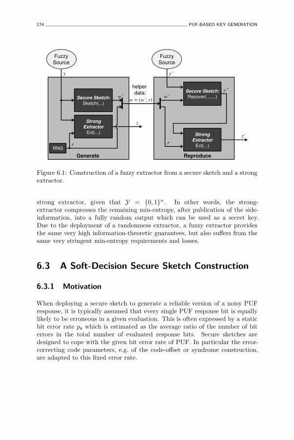
174 PUF-BASED KEY GENERATION
\´
Secure Sketch:
Sketch(...)
Secure Sketch:
Recover(...,...)
Strong
Extractor
Ext(...)
y \
z
RNG r
Z
Strong
Extractor
Ext(...)
]
w = (Z¶��U) Z
r
Fuzzy
Source Fuzzy
Source
helper
data:
Generate Reproduce
Figure 6.1: Construction of a fuzzy extractor from a secure sketch and a strongextractor.
strong extractor, given that Y = {0, 1}n. In other words, the strong-extractor compresses the remaining min-entropy, after publication of the side-information, into a fully random output which can be used as a secret key.Due to the deployment of a randomness extractor, a fuzzy extractor providesthe same very high information-theoretic guarantees, but also suffers from thesame very stringent min-entropy requirements and losses.
6.3 A Soft-Decision Secure Sketch Construction
6.3.1 Motivation
When deploying a secure sketch to generate a reliable version of a noisy PUFresponse, it is typically assumed that every single PUF response bit is equallylikely to be erroneous in a given evaluation. This is often expressed by a staticbit error rate pe which is estimated as the average ratio of the number of biterrors in the total number of evaluated response bits. Secure sketches aredesigned to cope with the given bit error rate of PUF. In particular the error-correcting code parameters, e.g. of the code-offset or syndrome construction,are adapted to this fixed error rate.
A SOFT-DECISION SECURE SKETCH CONSTRUCTION 175
In [91], we argue that at least for SRAM PUFs, the assumption of a single fixederror rate is too simplistic and too pessimistic. When analyzing experimentaldata from an SRAM PUF experiment, it is readily observed that the largemajority of the response bits are extremely robust, i.e. they never or hardlyever will change their value between evaluations. A minority of bits are morenoisy, occasionally presenting a bit error, and a few bits have no preferred valueat all and are basically completely random at each evaluation. This means thatevery SRAM PUF response bit has its own individual error probability, andthe values of these error probabilities are themselves randomly distributed foreach bit. In [91] we succeeded in deriving an expression for this distributionbased on a simplified model of the construction and operation of an SRAMPUF, and experimentally verified the accuracy of this distribution.
From this observation, it follows that an assumed fixed error probability of pe
for every SRAM PUF response bit is an overestimation for a large majority ofbits. A secure sketch designed for such a fixed error rate will hence be overlyconservative for most bits. A more efficient secure sketch would take intoaccount the individual likelihood for every response bit to be wrong. Thisis precisely what a secure sketch based on a soft-decision error correctiondecoder could achieve, given that soft-decision information for the responsebits is available. We call this a soft-decision secure sketch. For an SRAM PUF,soft-decision information for the response bits can be obtained by measuringevery bit many times and publishing the observed individual error probabilitiesas helper data for the soft-decision secure sketch. In [91], we have demonstratedthat at least for SRAM PUFs this is a possibility, since the publication of theseprobabilities does not induce any additional min-entropy loss for the actualunpredictable values of every response bit.
6.3.2 Soft-Decision Error Correction
Soft-decision error correction is a generalization of discrete (hard-decision)error correction. Besides using the redundancy in a codeword to achieve errorcorrection, like a hard-decision decoder, soft-decision decoding will also considerthe estimated reliability of every bit in a codeword and will adapt its correctionstrategy based on this soft-decision information. As a result, soft-decisiondecoders are typically more efficient than their hard-decision counterparts,i.e. they can correct more bit errors based on the same amount of redundancy,or equivalently they can achieve the same correction capability by using acode with less redundancy. For the code-offset and syndrome constructions ofsecure sketches, based on a binary linear block code with parameters [n, k, t],the redundancy of (n− k) bits is precisely the amount of (min-)entropy whichis lost due to the publication of the helper data. When a soft-decision decoder
176 PUF-BASED KEY GENERATION
is used, less redundancy is needed and hence less (min-)entropy is lost. Thisresults in a relaxed requirement on the number of PUF response bits which areneeded to derive a key of a particular length, and ultimately in a smaller PUFimplementation.
Two well known soft-decision decoding algorithms are the Viterbi algorithmfor convolution codes, as proposed by Viterbi [151], and the belief propagationalgorithm for LDPC codes, as proposed by Gallager [44]. However, both typesare not really adequate for use in typical secure sketch constructions sincethey require very long data streams to work efficiently, while the length of afuzzy secret such as a PUF response is often limited. We would like to use asoft-decision decoding algorithm for rather short linear block codes in order tomaintain efficiency. Although less common, soft-decision decoding techniquesfor short linear block codes exist.
Soft-decision Maximum-Likelihood Decoding (SDML)
Soft-decision maximum-likelihood decoding (SDML) is a straightforwardalgorithm that selects the code word that was most likely transmitted basedon the bit reliabilities. SDML achieves the best error-correcting performancepossible, but generally at a decoding complexity exponential in the codedimension k. Repetition codes (k = 1) can still be efficiently SDML decoded.Conversely, for k = n SDML decoding degenerates to making a hard decisionon every bit individually only based on its reliability, and for k = n − 1 theblock code is a parity-check code and SDML decoding is done efficiently byflipping the least reliable bit to match the parity. This last technique is alsoknown as Wagner decoding and is described by Silverman and Balser [134].
Generalized Multiple Concatenated (GMC) Decoding of Reed-Muller Codes
An r-th order Reed-Muller code RM(r, m), is a binary linear block code withparameters [n = 2m, k =
∑ri=0
(mi
), t = 2m−r−1 − 1]. It is well known that
RM(r, m) can be decomposed into the concatenation of two shorter innercodes, RM(r − 1, m − 1) and RM(r, m − 1), and a simple length-2 blockcode as outer code. This decomposition can be applied recursively until onereaches RM(0, m′), which is a repetition code, or RM(r′ − 1, r′) (or RM(r′, r′)),which is a parity check (or degenerated) code, all of which can be efficientlysoft-decision decoded with SDML. This technique, introduced as GeneralizedMultiple Concatenated decoding (GMC) by Schnabl and Bossert [127], yieldsa much lower decoding complexity than SDML, but only a slightly decreasederror-correcting capability.
A SOFT-DECISION SECURE SKETCH CONSTRUCTION 177
6.3.3 Soft-Decision Secure Sketch Design
Soft-Decision Secure Sketch
In [90], we propose a practical soft-decision secure sketch based on the code-offset construction deploying a concatenated soft-decision decoding of an innerrepetition code and an outer Reed-Muller code. Soft-decision informationis obtained from response bits during the initial generation procedure andpublished as helper data. The soft-decision information represents the log-likelihood for every bit to be wrong, which is calculated from the estimatederror probability pe(i) of response bit i as:
Ki = ⌊logβ1−pe(i)
pe(i) ⌉ .
The log-likelihoods are represented as an 8-bit two’s-complement integer valueand the logarithm base β is chosen to avoid overflows in this representation.
In the recovery phase of the secure sketch, the regular helper data is combinedwith the PUF response evaluation to construct a noisy codeword c′ as for theregular code-offset construction described in Section 6.2.1. The bits of thisnoisy codeword are now combined with the log-likelihood soft-decision helperdata to derive the soft-decision input of the decoder algorithms as follows:
Li = (−1)c′
i ·Ki ,
i.e. ‘0’ code bits become positive log-likelihoods, and ‘1’ code bits negative ones.
Soft-Decision Decoding Algorithms
SDML repetition decoding of soft-decision information L amounts to calcu-lating L∗ =
∑n−1i=0 Li. The most-likely transmitted code word was all zeros
if L∗ > 0 and all ones if L∗ < 0. Moreover, the magnitude of L∗ givesa reliability for this decision which allows to perform a second soft-decisiondecoding for the outer code. Algorithm 1 outlines the simple operation for theSDML decoding of a repetition code. As an outer code, we use a RM(r, m)code and decode it with an adapted version of the soft-decision GMC decodingalgorithm as introduced by Schnabl and Bossert [127]. The soft-decision outputof the repetition decoder is used as input by the GMC decoder. The operationof the GMC decoder we use is given by Algorithm 2. Note that this a recursivealgorithm, calling itself twice if 0 < r < m.
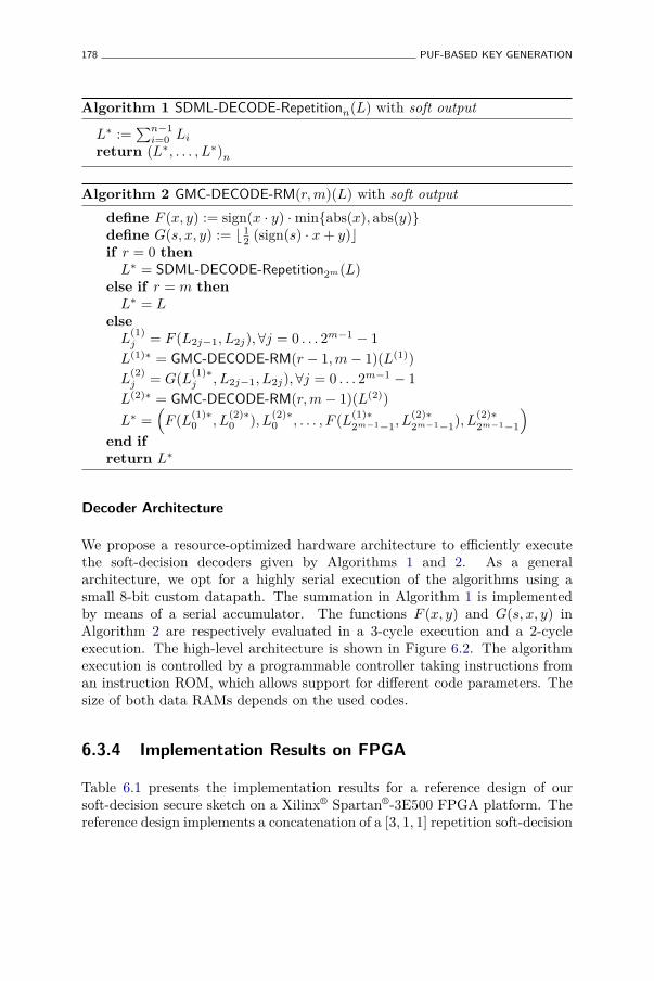
178 PUF-BASED KEY GENERATION
Algorithm 1 SDML-DECODE-Repetitionn(L) with soft output
L∗ :=∑n−1
i=0 Li
return (L∗, . . . , L∗)n
Algorithm 2 GMC-DECODE-RM(r, m)(L) with soft output
define F (x, y) := sign(x · y) ·min{abs(x), abs(y)}define G(s, x, y) := ⌊ 1
2 (sign(s) · x + y)⌋if r = 0 then
L∗ = SDML-DECODE-Repetition2m(L)else if r = m then
L∗ = Lelse
L(1)j = F (L2j−1, L2j),∀j = 0 . . . 2m−1 − 1
L(1)∗ = GMC-DECODE-RM(r − 1, m− 1)(L(1))L
(2)j = G(L(1)∗
j , L2j−1, L2j),∀j = 0 . . . 2m−1 − 1
L(2)∗ = GMC-DECODE-RM(r, m− 1)(L(2))
L∗ =(
F (L(1)∗0 , L
(2)∗0 ), L
(2)∗0 , . . . , F (L(1)∗
2m−1−1, L(2)∗2m−1−1), L
(2)∗2m−1−1
)
end ifreturn L∗
Decoder Architecture
We propose a resource-optimized hardware architecture to efficiently executethe soft-decision decoders given by Algorithms 1 and 2. As a generalarchitecture, we opt for a highly serial execution of the algorithms using asmall 8-bit custom datapath. The summation in Algorithm 1 is implementedby means of a serial accumulator. The functions F (x, y) and G(s, x, y) inAlgorithm 2 are respectively evaluated in a 3-cycle execution and a 2-cycleexecution. The high-level architecture is shown in Figure 6.2. The algorithmexecution is controlled by a programmable controller taking instructions froman instruction ROM, which allows support for different code parameters. Thesize of both data RAMs depends on the used codes.
6.3.4 Implementation Results on FPGA
Table 6.1 presents the implementation results for a reference design of oursoft-decision secure sketch on a Xilinx® Spartan®-3E500 FPGA platform. Thereference design implements a concatenation of a [3, 1, 1] repetition soft-decision
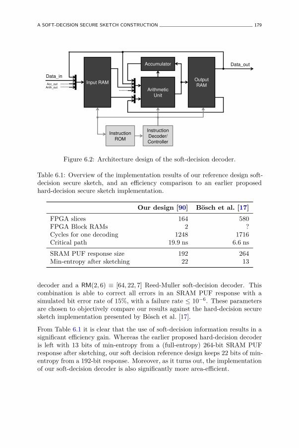
A SOFT-DECISION SECURE SKETCH CONSTRUCTION 179
Input RAM Output
RAM
Accumulator
Arithmetic
Unit
Data_in
Data_out
Acc_out Arith_out
Instruction
ROM
Instruction
Decoder/
Controller
Figure 6.2: Architecture design of the soft-decision decoder.
Table 6.1: Overview of the implementation results of our reference design soft-decision secure sketch, and an efficiency comparison to an earlier proposedhard-decision secure sketch implementation.
Our design [90] Bösch et al. [17]
FPGA slices 164 580FPGA Block RAMs 2 ?Cycles for one decoding 1248 1716Critical path 19.9 ns 6.6 ns
SRAM PUF response size 192 264Min-entropy after sketching 22 13
decoder and a RM(2, 6) ≡ [64, 22, 7] Reed-Muller soft-decision decoder. Thiscombination is able to correct all errors in an SRAM PUF response with asimulated bit error rate of 15%, with a failure rate ≤ 10−6. These parametersare chosen to objectively compare our results against the hard-decision securesketch implementation presented by Bösch et al. [17].
From Table 6.1 it is clear that the use of soft-decision information results in asignificant efficiency gain. Whereas the earlier proposed hard-decision decoderis left with 13 bits of min-entropy from a (full-entropy) 264-bit SRAM PUFresponse after sketching, our soft decision reference design keeps 22 bits of min-entropy from a 192-bit response. Moreover, as it turns out, the implementationof our soft-decision decoder is also significantly more area-efficient.
180 PUF-BASED KEY GENERATION
6.4 Practical PUF-based Key Generation
6.4.1 Motivation
The main rationale behind what we call practical PUF-based key generationis that we abandon the requirement of generating information-theoreticallyrandom keys and instead aim for cryptographically secure randomness based onreasonable assumptions and best-practice techniques, aiming to gain in overallefficiency. While representing a certain sacrifice in security from a theoreticalperspective, the abandonment of information-theoretical randomness can beconvincingly motivated from a practical viewpoint:
• As argued in Section 6.2.2, the choice for information-theoreticalrandomness comes at a direct implementation cost for the randomnesssource due to the unavoidable and large min-entropy losses in the strongextractor.
• Information-theoretical randomness is conditioned on strong min-entropyguarantees for the randomness source. In practice it is very oftenimpossible to provide a reasonably accurate estimation of a source’s min-entropy, let alone a guarantee thereon. If such guarantees cannot beprovided, it doesn’t make much sense to consider information-theoreticalrandomness any further.
• For most applications, information-theoretical randomness is not strictlyrequired. In fact, apart from a few notable exceptions, nearly all practicalcryptographic primitives are themselves not information-theoretically se-cure operations, which makes the requirement of information-theoreticalrandomness a practical exaggeration.
• Most currently deployed security systems and key generators do not useinformation-theoretical randomness, but also apply a more pragmaticpractical approach based on seeded PRNGs, as detailed in Section 6.2.2.
6.4.2 Practical Key Generation from a Fuzzy Source
Practical Secure Sketch
The secure sketch, as defined in Definition 26 is already practical in the sensethat it can be constructed quite efficiently, as demonstrated by the code-offsetand the syndrome construction described in Section 6.2.1, and its efficiency is
PRACTICAL PUF-BASED KEY GENERATION 181
typically only limited by the efficiency of the underlying error-correcting codes.We propose a slightly more generalized definition of a secure sketch which willprove its use in the practical fuzzy extractor we describe next.
Definition 30. An (ℓ, pe, µ, pfail, µ′)-practical secure sketch is a pair of efficient(possibly randomized) procedures Sketch : {0, 1}ℓ → {0, 1}∗ : y → w andRecover : {0, 1}ℓ × {0, 1}∗ → {0, 1}ℓ : (y′, w) → y′′, with the following twoproperties:
• The correctness property of a practical secure sketch guarantees that if
Pr (HD (Y ; Y ′) ≤ t) ≥ Fbino(t; ℓ, pe) ,
then
Pr (Y 6= Recover(Y ′, Sketch(Y ))) ≤ pfail .
• The security property of a practical secure sketch guarantees that ifρ(Y ) ≥ µ then ρ(Y |W ) ≥ µ′.
It is clear that a practical secure sketch is very similar to a secure sketch asdefined in Definition 26, and can be built with the same constructions describedin Section 6.2.1. However, both the correctness and the security property areslightly relaxed:
• The correctness property is no longer conditioned on a hard limit onthe number of errors, but instead on an error rate parameter pe whichdescribes the probability of a number of differing bits by means of abinomial distribution. An even further generalization can be made byconsidering a generic cumulative distribution function of the errors on thefuzzy secret, but the binomial case will suffice for our use. Equivalently,the recovery is no longer hard guaranteed, but is only certain up toa certain failure probability pfail. This generalization more accuratelycaptures realistic scenarios where hard bounds on error rates can onlyrarely be provided.
• The security property is also more relaxed since it is no longer conditionedon the min-entropy, but only on the Shannon entropy (density) of thefuzzy secret. Equivalently, it only provides a guarantee about theShannon entropy (density) of the output.
Practical Fuzzy Extractor
In analogy to practical secure sketches, we also propose a practical fuzzyextractor:
182 PUF-BASED KEY GENERATION
Definition 31. An (ℓ, pe, µ, pfail, m)-practical fuzzy extractor is a pair ofefficient (possibly randomized) procedures
Generate : {0, 1}ℓ → {0, 1}m × {0, 1}∗ : y → (z, w) ,
and
Reproduce : {0, 1}ℓ × {0, 1}∗ → {0, 1}m : (y′, w)→ z ,
with the following two properties:
• The correctness property of a practical key generator guarantees that if
Pr (HD (Y ; Y ′) ≤ t) ≥ Fbino(t; ℓ, pe) ,
and (Z, W )← Generate(Y ), then
Pr (Z 6= Reproduce(Y ′, W )) ≤ pfail .
• The security property of a practical key generator states that if ρ(Y ) ≥ µ,then Z is the result of an entropy accumulation over at least m bits ofentropy: Z ← Acc(S), with H(S|W ) ≥ m.
It is clear that this practical fuzzy extractor is a variant of a fuzzy extractorwith relaxed conditions. As a consequence, the practical key generator does nolonger produce an information-theoretically secure random output. However,through the use of a secure entropy accumulator as described in Section 6.2.2,the produced output is still at least as random as that of secure cryptographicPRNGs which are currently widely used in practice to generate secure keysfrom low-entropy physical randomness sources.
It is evident that an (ℓ, pe, µ, pfail, m)-practical fuzzy extractor can be straight-forwardly constructed from an (ℓ, pe, µ, pfail, µ′)-practical secure sketch and anm-bit entropy accumulator with m ≤ µ′ℓ, in the same way as a regular fuzzyextractor is constructed from a secure sketch and a randomness extractor. Theconstruction of a practical fuzzy extractor is shown in Figure 6.3.
Design and Design Constraints of a Practical Fuzzy Extractor Construction
We propose a design of a (ℓ, pe, µ, pfail, m)-practical fuzzy extractor basedon a syndrome construction for the practical secure sketch and an m-bitcryptographic hash function for the entropy accumulator. When the syndromeconstruction deploys an [n, k, t] linear block code C, a number of designconstraints on the parameters of usable codes can be derived:
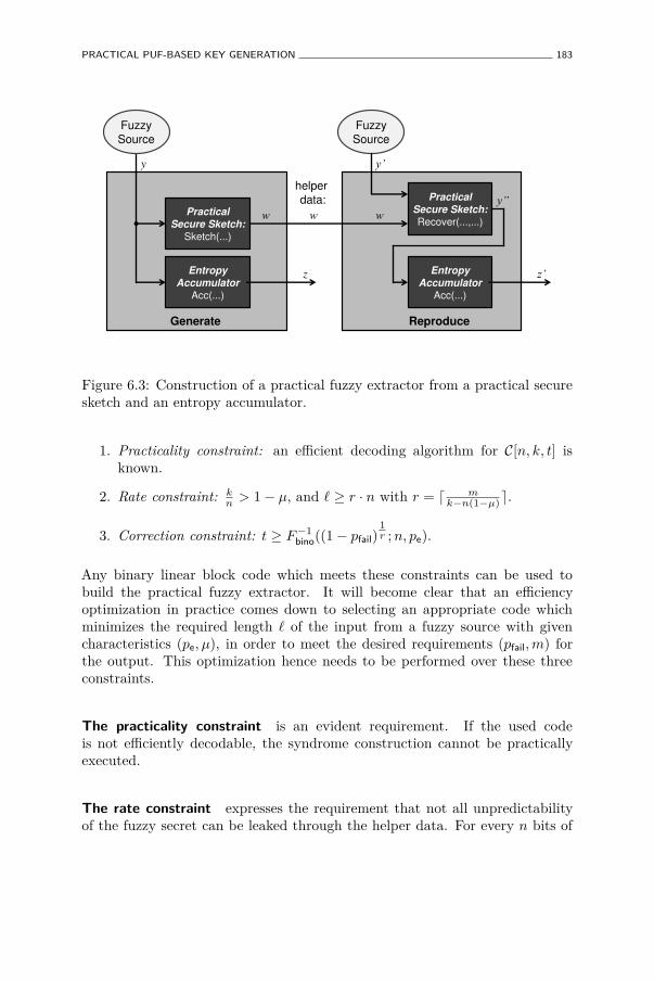
PRACTICAL PUF-BASED KEY GENERATION 183
Practical
Secure Sketch:
Sketch(...)
Practical
Secure Sketch:
Recover(...,...)
Entropy
Accumulator
Acc(...)
y \
z
w
Entropy
Accumulator
Acc(...)
]
\´
w w
Fuzzy
Source Fuzzy
Source
helper
data:
Generate Reproduce
Figure 6.3: Construction of a practical fuzzy extractor from a practical securesketch and an entropy accumulator.
1. Practicality constraint: an efficient decoding algorithm for C[n, k, t] isknown.
2. Rate constraint: kn
> 1− µ, and ℓ ≥ r · n with r = ⌈ mk−n(1−µ)⌉.
3. Correction constraint: t ≥ F−1bino((1− pfail)
1r ; n, pe).
Any binary linear block code which meets these constraints can be used tobuild the practical fuzzy extractor. It will become clear that an efficiencyoptimization in practice comes down to selecting an appropriate code whichminimizes the required length ℓ of the input from a fuzzy source with givencharacteristics (pe, µ), in order to meet the desired requirements (pfail, m) forthe output. This optimization hence needs to be performed over these threeconstraints.
The practicality constraint is an evident requirement. If the used codeis not efficiently decodable, the syndrome construction cannot be practicallyexecuted.
The rate constraint expresses the requirement that not all unpredictabilityof the fuzzy secret can be leaked through the helper data. For every n bits of
184 PUF-BASED KEY GENERATION
the fuzzy secret, a helper data string of (n−k) bits is generated. The remainingconditional entropy in the n bits of the fuzzy secret is at least n ·µ− (n− k) =k − n(1 − µ). To have any arguable entropy left which can be accumulated,this quantity needs to be strictly positive, from which the first part of the rateconstraint immediately follows. Even if the remaining entropy per n-bit fuzzyinput is positive, the construction still requires at least r = ⌈ m
k−n(1−µ)⌉ suchn-bit inputs from the fuzzy source in order to accumulate m bits of entropy.
The correction constraint expresses the requirement that the used code needsto be able to correct a minimal amount of bit errors for the construction tomeet the overall failure rate. The probability of a successful recovery of a singlen-bit fuzzy input is at least Pr (HD (Y n; Y ′n) ≤ t) = Fbino(t; n, pe) and for theoverall construction this is repeated r times, hence the overall success rate isat least Fbino(t; n, pe)r ≥ 1 − pfail. From this, the correction constraint on theused code immediately follows.
Extension to Concatenated Codes
Often, fuzzy sources, e.g. intrinsic PUFs, have relatively high error rates, up to10% and even more. Single linear block codes have difficulties in reducing suchhigh error rates to a practically acceptable failure rate, which means that onlyexcessively long codes and/or codes with relatively low rates can be used. Thisrestriction can be relaxed through the use of code concatenation, i.e. using two(or more) block codes one after the other. Typically, a simple but robust innerblock code brings down the relatively high error rate to a lower intermediateerror probability, and a more advanced outer block code can then achieve a verylow final failure rate much more efficiently. The power of code concatenationin the context of fuzzy extractors was first discussed by Bösch et al. [17].
We extend our proposed practical fuzzy extractor construction by deployingcode concatenation. In particular, we consider using a [nREP = 2tREP + 1, 1, tREP]repetition code as the inner code. A repetition code en/decoder is triviallysimple to implement with a very low overhead, and is more efficient on higherror rates than more advanced block codes. The outer code can still be any[n2, k2, t2] binary linear block code C2. Following the same reasoning as above,the design constraints for this extended construction then become:
1. Practicality constraint: an efficient decoding algorithm for C2[n2, k2, t2] isknown. (Efficient decoding of the repetition code is trivial.)
2. Rate constraint: k2
nREPn2> 1− µ,
and ℓ ≥ r · nREPn2 with r = ⌈ mk2−nREPn2(1−µ)⌉.
PRACTICAL PUF-BASED KEY GENERATION 185
3. Correction constraint: t2 ≥ F−1bino((1− pfail)
1r ; n, p′e),
with p′e = 1− Fbino(tREP; nREP, pe).
6.4.3 Comparison of Key Generation with Intrinsic PUFs
A practical fuzzy extractor can be directly used to generate PUF-based keysof cryptographic quality, when an accurate characterization of the used PUF’sresponse distribution in terms of binary error rate (pe) and response entropydensity (µ) is available. These are exactly the quantifiers we obtained from theeight experimentally verified intrinsic PUF constructions discussed in Chapter 4and which are summarized in Table 4.10. We will now use these quantifiers incombination with the practical fuzzy extractor design presented in Section 6.4.2to assess the key generation efficiency of the different intrinsic PUFs.
Concrete Practical Fuzzy Extractor Implementation
We consider a practical fuzzy extractor design that deploys the syndromeconstruction practical secure sketch based on a concatenation of a binaryrepetition code as an inner code and a binary BCH code as an outer code. BCHcodes are a class of particularly efficient linear block codes for which efficientdecoding algorithms exist. Binary BCH codes with parameters [nBCH, kBCH, tBCH]are defined for nBCH = 2u − 1, but through the use of code word shortening,BCH codes of any length [nBCH = 2u − 1 − s, kBCH − s, tBCH] can be constructed.For the comparison, we assume that a generic BCH decoder is available whichcan efficiently decode code lengths up to nBCH = 2047. In Section 6.4.4 weargue that this is a reasonable assumption by presenting a hardware designand efficient implementation of such a decoder. For the entropy accumulatorwe consider an implementation of a secure cryptographic hash function whichgenerates m-bit outputs. The output of the practical fuzzy extractor is therunning hash value of the recovered fuzzy inputs.
Comparison of Optimized Key Generation Efficiencies
A PUF-based key generator is constructed from each of the eight studiedintrinsic PUFs with parameters (p̂intra
P , ρ(Y ℓ)) as summarized in Table 4.10, and a(ℓ, p̂intra
P , ρ(Y ℓ), pfail, m)-practical fuzzy extractor design as presented above. Fora given key requirement (pfail, m), the overall construction is optimized to needthe smallest possible number of PUF response bits ℓ, since the implementationcost of the PUF generally scales with ℓ. For both arbiter-based PUFs, the
186 PUF-BASED KEY GENERATION
optimization goal is slightly different: they require the least amount of fuzzyinputs, as expressed by r in the constraints, since each input needs to begenerated from a different arbiter PUF. This is a result of the decreasing entropydensity of an arbiter PUF’s responses when their length increases. In both cases,the optimization is performed over the constraints expressed in Section 6.4.2(the extended construction with code concatenation).
The obtained optimal code selections and corresponding implementation resultsfor each of the eight intrinsic PUF constructions, and for each of three keyrequirements, is presented in Table 6.2. The considered key requirements are:
1. A 128-bit generated key with failure rate at most 10−6;
2. A 128-bit generated key with failure rate at most 10−9;
3. A 256-bit generated key with failure rate at most 10−12.
The required silicon area is also calculated in the same manner (and with thesame disclaimers) as described in Section 5.2.3. It is immediately clear thatthe latch PUF, the D flip-flop PUF and the basic arbiter PUF are not able togenerate a key even for the most relaxed key requirements, i.e. no combinationof code parameters can be found meeting the design constraints. This is eitherdue to a too large intra-distance, a too low entropy density, or a combinationof both. The SRAM PUF again performs particularly well, but so does the 2-XOR arbiter PUF. Both types of ring oscillator PUFs also manage to producea key for all three key requirements, but at a considerably higher silicon areacost than the SRAM and the 2-XOR arbiter PUFs. The buskeeper can onlyproduce a key for the first two requirements, and only at a very large area costwhich is the result of its relatively large intra-distance.
Note that the results presented in Table 6.2 are based on the estimated entropydensities for the different PUF constructions as summarized in Table 4.10 andin Figure 4.5, and these estimations are only upper bounds. Any more accurate(i.e. lower) entropy upper bounds will also affect these key generation results.Especially for the arbiter-based PUFs, we want to point out that the consideredentropy bounds are only based on rather basic modeling attacks, and moreadvanced modeling attacks will result in lower entropy density estimations.The results presented in Table 6.2 should be interpreted in that context.
6.4.4 A Full-Fledged Practical Key Generator Implementation
In [92], we demonstrate the practical nature of the methods and primitivesintroduced in Section 6.4.2 by designing and implementing a complete, front-
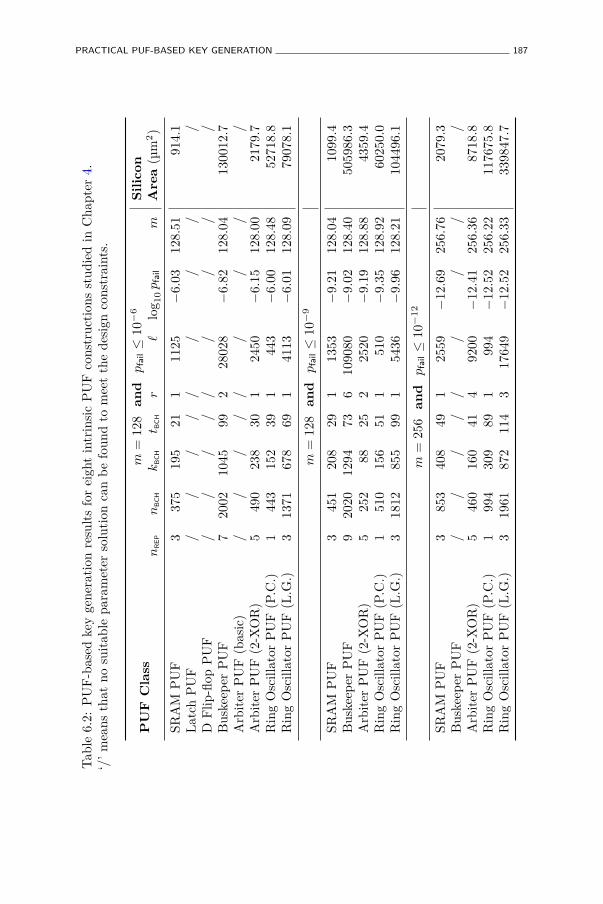
PRACTICAL PUF-BASED KEY GENERATION 187
Tab
le6.
2:P
UF
-bas
edke
yge
nera
tion
resu
lts
for
eigh
tin
trin
sic
PU
Fco
nstr
ucti
ons
stud
ied
inC
hapt
er4.
‘/’
mea
nsth
atno
suit
able
para
met
erso
luti
onca
nb
efo
und
tom
eet
the
desi
gnco
nstr
aint
s.
PU
FC
lass
m=
128
an
dp
fail≤
10−
6S
ilic
on
Are
a(µ
m2)
nR
EP
nB
CH
kB
CH
t BC
Hr
ℓlo
g 10
pfa
ilm
SRA
MP
UF
337
519
521
111
25−
6.03
128.
5191
4.1
Lat
chP
UF
//
//
//
//
/D
Flip
-flop
PU
F/
//
//
//
//
Bus
keep
erP
UF
720
0210
4599
228
028
−6.
8212
8.04
1300
12.7
Arb
iter
PU
F(b
asic
)/
//
//
//
//
Arb
iter
PU
F(2
-XO
R)
549
023
830
124
50−
6.15
128.
0021
79.7
Rin
gO
scill
ator
PU
F(P
.C.)
144
315
239
144
3−
6.00
128.
4852
718.
8R
ing
Osc
illat
orP
UF
(L.G
.)3
1371
678
691
4113
−6.
0112
8.09
7907
8.1
m=
128
an
dp
fail≤
10−
9
SRA
MP
UF
345
120
829
113
53−
9.21
128.
0410
99.4
Bus
keep
erP
UF
920
2012
9473
610
9080
−9.
0212
8.40
5059
86.3
Arb
iter
PU
F(2
-XO
R)
525
288
252
2520
−9.
1912
8.88
4359
.4R
ing
Osc
illat
orP
UF
(P.C
.)1
510
156
511
510
−9.
3512
8.92
6025
0.0
Rin
gO
scill
ator
PU
F(L
.G.)
318
1285
599
154
36−
9.96
128.
2110
4496
.1
m=
256
an
dp
fail≤
10−
12
SRA
MP
UF
385
340
849
125
59−
12.6
925
6.76
2079
.3B
uske
eper
PU
F/
//
//
//
//
Arb
iter
PU
F(2
-XO
R)
546
016
041
492
00−
12.4
125
6.36
8718
.8R
ing
Osc
illat
orP
UF
(P.C
.)1
994
309
891
994
−12
.52
256.
2211
7675
.8R
ing
Osc
illat
orP
UF
(L.G
.)3
1961
872
114
317
649
−12
.52
256.
3333
9847
.7
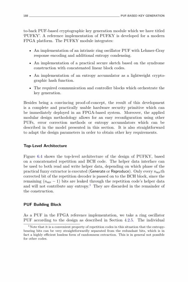
188 PUF-BASED KEY GENERATION
to-back PUF-based cryptographic key generation module which we have titled‘PUFKY’. A reference implementation of PUFKY is developed for a modernFPGA platform. The PUFKY module integrates:
• An implementation of an intrinsic ring oscillator PUF with Lehmer-Grayresponse encoding and additional entropy condensing.
• An implementation of a practical secure sketch based on the syndromeconstruction with concatenated linear block codes.
• An implementation of an entropy accumulator as a lightweight crypto-graphic hash function.
• The required communication and controller blocks which orchestrate thekey generation.
Besides being a convincing proof-of-concept, the result of this developmentis a complete and practically usable hardware security primitive which canbe immediately deployed in an FPGA-based system. Moreover, the appliedmodular design methodology allows for an easy reconfiguration using otherPUFs, error correction methods or entropy accumulators which can bedescribed in the model presented in this section. It is also straightforwardto adapt the design parameters in order to obtain other key requirements.
Top-Level Architecture
Figure 6.4 shows the top-level architecture of the design of PUFKY, basedon a concatenated repetition and BCH code. The helper data interface canbe used to both read and write helper data, depending on which phase of thepractical fuzzy extractor is executed (Generate or Reproduce). Only every nREPthcorrected bit of the repetition decoder is passed on to the BCH block, since theremaining (nREP − 1) bits are leaked through the repetition code’s helper dataand will not contribute any entropy.1 They are discarded in the remainder ofthe construction.
PUF Building Block
As a PUF in the FPGA reference implementation, we take a ring oscillatorPUF according to the design as described in Section 4.2.5. The individual
1Note that it is a convenient property of repetition codes in this situation that the entropy-bearing bits can be very straightforwardly separated from the redundant bits, which is infact a highly efficient lossless form of randomness extraction. This is in general not possiblefor other codes.
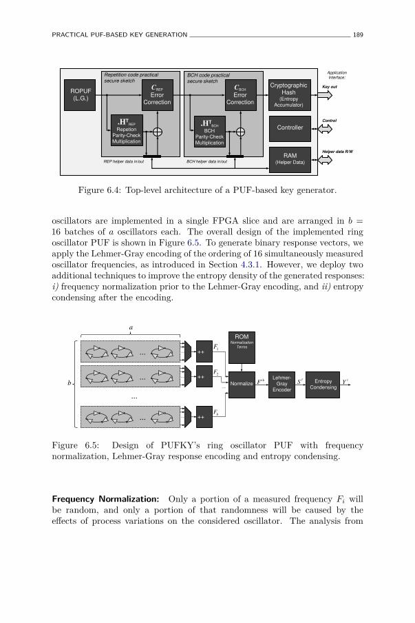
PRACTICAL PUF-BASED KEY GENERATION 189
Helper data R/W
ROPUF
(L.G.)
.HTREP
Repetion
Parity-Check
Multiplication
.HTBCH
BCH
Parity-Check
Multiplication
CREP
Error
Correction
CBCH
Error
Correction
Repetition code practical
secure sketch BCH code practical
secure sketch
BCH helper data in/out
Cryptographic
Hash (Entropy
Accumulator)
REP helper data in/out
Key out
Controller
Control
RAM (Helper Data)
Application Interface:
Figure 6.4: Top-level architecture of a PUF-based key generator.
oscillators are implemented in a single FPGA slice and are arranged in b =16 batches of a oscillators each. The overall design of the implemented ringoscillator PUF is shown in Figure 6.5. To generate binary response vectors, weapply the Lehmer-Gray encoding of the ordering of 16 simultaneously measuredoscillator frequencies, as introduced in Section 4.3.1. However, we deploy twoadditional techniques to improve the entropy density of the generated responses:i) frequency normalization prior to the Lehmer-Gray encoding, and ii) entropycondensing after the encoding.
... ... ++
... ... ++
... ... ++
...
...
ROM Normalization
Terms
Lehmer- Gray
Encoder
Entropy
Condensing Normalize
1F
2F
bF
bF c
"cS
a
b"
Y
Figure 6.5: Design of PUFKY’s ring oscillator PUF with frequencynormalization, Lehmer-Gray response encoding and entropy condensing.
Frequency Normalization: Only a portion of a measured frequency Fi willbe random, and only a portion of that randomness will be caused by theeffects of process variations on the considered oscillator. The analysis from
190 PUF-BASED KEY GENERATION
Maiti et al. [95] demonstrates that Fi is subject to both device-dependent andoscillator-dependent structural bias. Device-dependent bias does not affect theordering of oscillators on a single device, so we will not consider it further.Oscillator-dependent structural bias on the other hand is of concern to us sinceit may have a severe impact on the randomness of the frequency ordering.From a probabilistic viewpoint, it is reasonable to assume the frequenciesFi to be independent, but due to the oscillator-dependent structural biaswe can not consider them to be identically distributed since each Fi has adifferent expected value E [Fi]. The ordering of Fi will be largely determinedby the deterministic ordering of E [Fi] and not by the effect of random processvariations on Fi. Fortunately, we are able to obtain an accurate estimate µ̃Fi
ofE [Fi] by averaging over many measurements of Fi on many devices. Embeddingthis estimate permanently in the design and subtracting it from the measuredfrequency gives us a normalized frequency F ′i = Fi−µ̃Fi
. Assuming µ̃Fi≈ E [Fi],
the resulting normalized frequencies F ′i will be independent and identicallydistributed (i.i.d.).
Entropy Condensing: Based on the i.i.d. assumption of the normalizedfrequencies, the resulting Lehmer-Gray encoding will have a full entropy ofH(Sℓ′
) =∑b
i=2 log2 i expressed in a vector of length ℓ′ =∑b
i=2⌈log2 i⌉. Thismeans the entropy density of this vector is already quite high; for the considereddesign with b = 16, this becomes ρ(Sℓ′
) = 44.2549 = 90.31%. However, this
density can be increased further by compressing it to Y ℓ with ℓ < ℓ′. Note thatSℓ′
is not quite uniform over {0, 1}ℓ′
since some bits of Sℓ′
are biased and/ordependent. This results from the fact that most of the Lehmer coefficients,although uniform by themselves, can take a range of values which is no integerpower of two, leading to a suboptimal binary encoding. We propose a simplecompression by selectively XOR-ing bits from Sℓ′
which suffer the most frombias and/or dependencies, leading to an overall increase of the entropy density.The price one pays for this entropy condensing operation is a slight reductionin absolute entropy of the responses, since XOR is a lossy operation, and aslight increase of the error rate of the response bits, by at most a factor ℓ′
ℓ.
For our reference implementation, we consider a condensing to ℓ = 42, yieldingρ(Y ℓ) = 97.95%.
Error-Correction Building Blocks
Both the repetition code parity-check multiplication and syndrome decoder areimplemented very efficiently in a fully combinatorial manner. The parity checkmultiplication of a BCH code is also implemented efficiently by means of anLFSR, which results from the special structure of a BCH code’s parity check
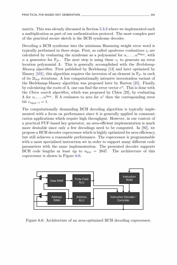
PRACTICAL PUF-BASED KEY GENERATION 191
matrix. This was already discussed in Section 5.3.3 where we implemented sucha multiplication as part of our authentication protocol. The most complex partof the practical secure sketch is the BCH syndrome decoder.
Decoding a BCH syndrome into the minimum Hamming weight error word istypically performed in three steps. First, so called syndrome evaluations zi arecalculated by evaluating the syndrome as a polynomial for α, . . . , α2tBCH , withα a generator for F2u . The next step is using these zi to generate an errorlocation polynomial Λ. This is generally accomplished with the Berlekamp-Massey algorithm. First published by Berlekamp [13] and later optimized byMassey [101], this algorithm requires the inversion of an element in F2u in eachof its 2tBCH iterations. A less computationally intensive inversionless variant ofthe Berlekamp-Massey algorithm was proposed later by Burton [25]. Finally,by calculating the roots of Λ, one can find the error vector en. This is done withthe Chien search algorithm, which was proposed by Chien [29], by evaluatingΛ for α, . . . , αtBCH . If Λ evaluates to zero for αi then the corresponding errorbit enBCH−i = 1.
The computationally demanding BCH decoding algorithm is typically imple-mented with a focus on performance since it is generally applied in communi-cation applications which require high throughput. However, in our context ofa practical PUF-based key generator, an area-efficient implementation is muchmore desirable since only a few decodings need to be computed. In [92], wepropose a BCH decoder coprocessor which is highly optimized for area efficiency,but still achieves a reasonable performance. The coprocessor is programmablewith a most specialized instruction set in order to support many different codeparameters with the same implementation. The presented decoder supportsBCH code lengths at least up to nBCH = 2047. The architecture of thiscoprocessor is shown in Figure 6.6.
Data RAM
Address
RAM
Finite Field
ALU
Address
ALU
Instruction
ROM
Instruction Decoder /
Controller
Figure 6.6: Architecture of an area-optimized BCH decoding coprocessor.
192 PUF-BASED KEY GENERATION
Entropy Accumulator
We use a cryptographic hash function as an entropy accumulator. For ourreference implementation, we implemented the lightweight SPONGENT-128hash function which was proposed by Bogdanov et al. [14].
Reference Implementation
The presented PUFKY reference design was synthesized and implemented on aXilinx® Spartan®-6 FPGA (XC6SLX45) which is a modern low-end FPGA in45 nm CMOS technology, specifically targeted for embedded system solutions.
Ring Oscillator PUF Characterization. The ring oscillator PUF implementa-tion, with a = 64 oscillators per batch, is characterized through an experimenton Npuf = 10 identical FPGA devices by measuring every ℓ = 42-bit responseon every device Nmeas = 25 times at nominal condition. A single FPGAwas also measured at two temperature corners αL = (Tenv = 10 °C) andαH = (Tenv = 80 °C) in order to assess temperature sensitivity. A conservativeworst-case bit error rate estimation of 13% (at the αH corner) is obtained.The entropy density of the PUF responses is assumed to be the optimalρ(Y ℓ) = 97.95% as a result of frequency normalization and entropy condensing.
FPGA Implementation Results. Based on the PUF characterization, we canoptimize the number of required PUF response bits over the constraints forthe code parameters. We aim for a key length m = 128 with failure ratepfail ≤ 10−9. After a thorough exploration of the design space with theseparameters, we converge on the following PUFKY reference implementation:
• A practical secure sketch applying a concatenation of a [7, 1, 3] repetitioncode and a [318, 174, 17] BCH code. The repetition block generates 36bits of helper data for every 42-bit PUF response and outputs 6 bits tothe BCH block. The BCH block generates 144 bits of helper data onceand feeds 318 bits to the entropy accumulator. The BCH decoder is onlyexecuted once (r = 1). The required number of bits is ℓ = 7×318 = 2226which can be provided by using a = ⌈ 2226
42 ⌉ = 53 oscillators per batchof the ring oscillator PUF, totalling to 53 × 16 = 848 oscillators for thewhole ring oscillator PUF.
• The PUF generates in total a × ℓ = 2226 bits containing a× ℓ× ρ(Y ℓ)= 2180.4 bits of entropy. The total helper data length is 53× 36 + 144
CONCLUSION 193
= 2052. The remaining entropy after secure sketching is at least2180.4− 2052 = 128.4 bits which are accumulated in an m = 128-bit keyby the SPONGENT-128 hash function implementation.
The total size of our PUFKY reference implementation for the consideredFPGA platform is 1162 slices, of which 82% is taken up by the ring oscillatorPUF. Table 6.3a lists the size of each submodule used in the design. The totaltime spent to extract the 128-bit key is approximately 5.62 ms (at 54 MHz).Table 6.3b lists the number of cycles spent in each step of the key extraction.
Table 6.3: Area consumption and runtime of our reference PUFKYimplementation on a Xilinx® Spartan® 6 FPGA. Due to slice compression andglue logic the sum of module sizes is not equal to total size. The PUF runtimeis independent of clock speed.
(a) Area consumption
ModuleSize
(slices)
ROPUF 952REP decoder 37BCH syndrome calc. 72BCH decoder 112SPONGENT-128 22data RAM 38
Total 1162
(b) Runtimes
Step of extractionTime
(cycles)
PUF output 4.59 msREP decoding 0BCH syndrome calc. 511BCH decoding 50320SPONGENT hashing 3990control overhead 489
Total @ 54 MHz 5.62 ms
6.5 Conclusion
In this chapter we have studied in detail the constructions and methodologiesrequired to generate a cryptographically secure key in a reliable manner from aPUF response, and we have presented a variety of new techniques and insightswhich make PUF-based key generation more efficient and practical.
In Section 6.3, we have introduced an important extension to secure sketchesby taking the soft-decision information of PUF response bits into account. Thisresults in a significant improvement with regard to the entropy loss induced bysecure sketches, leading to a large gain in PUF response efficiency as expressedby the results in Table 6.1. Moreover, a practical design and implementation
194 PUF-BASED KEY GENERATION
of such a soft-decision secure sketch has been presented which turns out to bemore area-efficient than all previously proposed implementations.
The notions of a practical secure sketch and a practical fuzzy extractor areintroduced in Section 6.4. These present a number of generalizations ofthe traditional concepts, the most important one being the abandonment ofinformation-theoretical security requirements in favor of the more practicaland efficient technique of entropy accumulation which is also widely used inimplementations of cryptographic PRNGs. We propose an efficient genericconstruction of a practical secure sketch and a practical fuzzy extractor andderive a number of parameter constraints for this construction. We use thesederived constraints to assess the key generation performance of the intrinsicPUFs studied in Chapter 4 in the newly proposed practical fuzzy extractorconstruction and present a comparative analysis in Table 6.2. From thisanalysis, it is clear that SRAM PUFs and also 2-XOR arbiter PUFs can beused to efficiently generate cryptographic keys.
Finally, to demonstrate the practicality of the newly proposed construction,we present a complete front-to-back PUF-based key generator design whichwe have called ‘PUFKY’, and a reference implementation on an FPGAplatform. This implementation contains a functional ring oscillator PUFwith Lehmer-Gray response encoding, an efficient practical secure sketchimplementation deploying a newly developed low-weight BCH decoder and anentropy accumulator implemented as a lightweight cryptographic hash function.This reference system generates 128-bit secure keys with a reliability ≥ 1−10−9,and can be directly instantiated as a hardware security IP core in an FPGA-based digital system.
Chapter 7
Conclusion and Future Work
Scio me nescire.
Socrates
Ignoramus et ignorabimus.
Emil du Bois-Reymond
Wir müssen wissen – wir werden wissen!
David Hilbert
7.1 Conclusions
PUFs are physical security primitives which enable trust in the context of digitalhardware implementations of cryptographic constructions, in particular theyare able to initiate physically unclonable and secure key generation and storage.In this thesis we have studied physically unclonable functions or PUFs, inparticular: i) their concept and constructions, ii) their properties, and iii) theirapplications as a physical root of trust, and the relations between these three.
In Chapter 2 we have introduced the concept of a physically unclonablefunction in great detail through an extensive study and analysis of earlier work
195
196 CONCLUSION AND FUTURE WORK
and existing constructions. Based on similar and distinguishing constructioncharacteristics, we have discussed strengths and weaknesses and possibleclassifications. The most noteworthy identified subclass are so-called intrinsicPUFs, i.e. PUF constructions which are based on internal evaluations ofimplicitly obtained random creation features, because they are particularlywell-fit for integration in larger security systems. It is however difficultto compare the practical value of different proposals from the literaturedue to a wide variety of implementation technologies and experimentalconsiderations. The lateral overview does present a good insight in recurringintrinsic PUF implementation techniques: i) amplification of microscopicunique features through differential measurement, ii) physical enhancementof PUF behavior through low-level (design-intensive) implementation control,and iii) algorithmic behavioral improvement through adapted post-processingtechniques.
In Chapter 3 we identify the most important usability and physical securityproperties attributed to PUFs and we have introduced clear definitions pointingout what exactly each of these properties signify. Through a comparativeanalysis on a representative subset of PUF constructions and a number ofimportant non-PUF reference cases, we have discovered which properties arereally defining for a PUF construction, and which are convenient additions butare in no way guaranteed for every PUF. As it turns out, the core definingproperty of a PUF is its physical unclonability. A second contribution ofthis chapter is the introduction of a formal framework for using PUFs, andmore general physical security primitives, in theoretical security reductionsat a higher level. We have defined robustness, physical unclonability andunpredictability in this framework.
With the goal of testing their security and usability characteristics as accuratelyand as objectively as possible, we have implemented and evaluated eightdifferent intrinsic PUF constructions on a 65 nm CMOS silicon platform. Thedesign process and the experimental results of this ASIC chip are described indetail in Chapter 4. The measurements of each of these eight constructions aretested for their reproducibility and their uniqueness through a characterizationof their respective intra- and inter-distance distributions using well-chosenstatistical parameters. The unpredictability of the studied PUFs is alsoestimated by proposing and evaluating a number of increasingly tighter upperbounds of the entropy density of their response bitstrings. The experimentsin this chapter yield the first ever objective comparison between multipledifferent intrinsic PUF constructions on the same platform, and a quantitativerepresentation of their primary characteristics which can be directly usedto assess their efficiency and performance in the following physical securityapplications.
FUTURE WORK 197
The first PUF-based security applications we consider in Chapter 5 areentity identification and authentication, as defined in Section 5.1.1. We firstelaborate on the identifiability property of PUFs and demonstrate how afuzzy identification scheme based on PUF responses can be set up, equivalentto biometric identification. Based on the measured characteristics of theeight intrinsic PUF construction studied in Chapter 4, we evaluate theiridentifying capabilities based on the typical fuzzy identification performancemetrics of false acceptance and rejection rates which are combined in receiver-operating characteristics and equal error rates. Next, we propose a new mutualauthentication protocol for PUF-carrying entities with significantly relaxedsecurity conditions for the used PUF such that it can deploy any intrinsic PUFconstruction. The primary innovative aspect of this protocol is an atypical useof an error-correction technique which results in a secure yet very lightweightauthentication solution. Based on this scheme, the authentication performanceand efficiency of the eight studied intrinsic PUFs is again compared.
Next, in Chapter 6, we discuss in detail the prerequisites and securityconsiderations for PUF-based secure key generation and storage, and presentand evaluate practical constructions and implementations. We first studyexisting techniques and constructions for enhancing the reliability of fuzzy data,so-called secure sketches, and for boosting the unpredictability of a derived key,either from an information-theoretic perspective, based on strong and fuzzyextractors, or from a practical perspective, based on entropy accumulators.The first main contribution of Chapter 6 is a new and significantly improvedconstruction of a secure sketch based on the innovative idea of using availablesoft-decision information of the PUF’s response bits. Secondly, we introducea practical generalization of fuzzy extractors in which we trade information-theoretical security for a large gain in efficiency, while still retaining adequatesecurity based on widely used best-practice entropy accumulation. Again, wetest the key generation capacity of the eight studied intrinsic PUFs, based ona proposed design of a practical fuzzy extractor. Lastly, to demonstrate thefeasibility and applicability of this design, we have made a fully functional,efficient yet flexible FPGA reference implementation of a PUF-based keygenerator, including a newly proposed ring-oscillator PUF with Lehmer-Grayresponse encoding, a practical secure sketch based on a new highly optimizedBCH decoder, and entropy accumulation with a lightweight hash function.
7.2 Future Work
The generic concept of a physically unclonable function was presented little overa decade ago, but the major research contributions on this topic are situated
198 CONCLUSION AND FUTURE WORK
in the last couple of years. PUFs are hence a relatively new subject in the fieldof physical security, and a number of interesting future research directions, aswell as some encountered open problems can be identified.
PUF Constructions. As pointed out a number of times in this thesis, oneof the major open questions on the side of PUF constructions is if, and how,an efficient truly unclonable intrinsic PUF, also called a strong PUF by someauthors, can be built. Some candidate circuits have been proposed, but theyare currently lacking any convincing argumentation of being unpredictablewhich is required for achieving mathematical and true unclonability. Due tothe difficulty of mathematically proving unpredictability based on physicalarguments, it is more convenient to assess unpredictability in relation tothe best known attack. This method has been applied successfully in thelast decades to cryptographic symmetric-key primitives. However, to makeindependent analysis possible, Kerckhoffs’ principle needs to be obeyed. Forphysical security primitives like PUFs, this entails that the full design andimplementation details of a proposed construction need to be disclosed. Amore practical alternative is to publish, in an easily accessible electronic format,extensive datasets of experimental PUF evaluations for public scrutiny. Wehope that the practical performance evaluation methods proposed in this thesiscan contribute to more meaningful and objective assessments of the value ofdifferent PUF constructions.
Another open issue is the construction of a physically reconfigurable PUF, asdiscussed in Section 2.5.3. Rather exotic suggestions were proposed but nevertested. A logically reconfigurable PUF is a good emulation from the behavioralperspective, but does not achieve the same strong physical security qualities.
Finally, as with all hardware (security) primitives, continuing research effort isrequired to develop increasingly more efficient constructions which offer bettertrade-offs and enable applications in resource-constrained environments.
PUF Properties. For PUF properties, we see the need for research effort ontwo levels. Firstly, on a practical level, more detailed methods and techniquesneed to be developed and investigated for assessing if, and to what extent, aproposed PUF constructions meets a particular property. For some properties,this is based on an analysis of the inter- and intra-distance distributions ofmeasured PUF responses, and a number of evaluation methods have beenproposed in this thesis. Presenting detailed and accurate statistics of thesedistributions is hence indispensable when proposing a new PUF construction.In-depth and independent analysis of a PUF’s construction and experimental
FUTURE WORK 199
results is required to assess its unpredictability, e.g. by means of tighter responseentropy bounds.
For other properties, an assessment is based on physical arguments and thisis again difficult to approach from a mathematical perspective. Qualities likephysical unclonability and tamper evidence can, and should only be assessedin a heuristic manner. Especially the core property of physical unclonabilityrequires special attention in that regard. A PUF which, through improvedphysical insights or technological progress, is found to be no longer physicallyunclonable, ceases to be a PUF.
On a more theoretical level, it needs to be further investigated how PUFs canbe deployed as formal primitives in a security system, i.e. allow theoreticaldesigners to reason about PUFs in a formal way without having to worryabout their physical aspects, which are often beyond their expertise. We haveproposed such a formal framework for describing physical functions and haveapplied to PUFs and their core properties. Extending this framework to otherprimitives and properties will be an interesting and fruitful exercise.
PUF Applications. In this thesis, we have demonstrated how to achieve twoprimary PUF-based security objectives: entity authentication and secure keygeneration/storage. We see further developments possible, both in tryingto achieve basic security objectives based on PUFs, as well as attemptingto integrate PUFs and PUF-based primitives securely and efficiently intolarger security systems. A noteworthy direction of the former which was notfurther discussed in this thesis is so-called hardware-entangled cryptography,i.e. designing basic cryptographic primitives which directly deploy a PUF asa building block. We introduced this approach in [9] and illustrated it with asecure design of a PUF-based block cipher.
To facilitate the further deployment of PUFs in security systems, we see thefollowing interesting and essential future challenges:
• A greater insight and effort on the low-level silicon circuit design ofintrinsic PUF constructions will result in increasingly more efficient(smaller, more robust, more random) structures.
• Both incremental and fundamental progress in the development andapplication of post-processing techniques required to use a PUF (relia-bility enhancement, randomness extraction, . . . ) is possible, e.g. the useof alternative error-correction techniques (non-binary codes, non-linearcodes, . . . ) and more insight in entropy accumulation techniques.

200 CONCLUSION AND FUTURE WORK
• Other physical security qualities of PUFs need to be considered, inparticular their resistance to side-channel attacks. Initial work on side-channel analysis of PUFs is recently introduced by Karakoyunlu andSunar [67], Merli et al. [103], but more elaborate research efforts arerequired.
To conclude, we expect that the continuous improvements and better under-standing of their practicality and of the physical as well as algorithmic securityof PUFs will enable and accelerate their further transition into common andnew security applications.
Appendix A
Notation and Definitionsfrom Probability Theory andInformation Theory
A.1 Probability Theory
A.1.1 Notation and Definitions
Variables and Sets. In this thesis we use the standard notions and definitionsof probability theory, such as a random event, a random variable and aprobability distribution. A random variable is typically denoted as an uppercase letter: Y , and a particular outcome thereof as the corresponding lowercase letter: Y = y. The set of all outcomes of Y is denoted by a calligraphicletter: Y. The number of elements in Y, also called the cardinality of Y isdenoted as #Y.
Vectors and Distances. If Y is a (random) vector, we denote its length(number of elements) as |Y |. Hamming distance is a distance metric betweentwo vectors of equal length and is defined as the number of positions in both
201
202 NOTATION AND DEFINITIONS FROM PROBABILITY THEORY AND INFORMATION THEORY
vectors with differing values:
HD (Y ; Y ′)△
= #{i : Yi 6= Y ′i } .
Often, the Hamming distance is expressed as a fraction of the vectors’ length,also called the fractional Hamming distance:
FHD (Y ; Y ′)△
=HD (Y ; Y ′)|Y |
.
The Hamming weight of a single vector is the number of positions with non-zerovalues:
HW (Y )△
= #{i : Yi 6= 0} .
The Euclidean distance between two real-values vectors is defined as:
||Y − Y ′||△
=|Y |∑
i=1
√(Yi − Y ′i )2 .
To make explicit that we consider a vector of length n, we also writeY n = (Y1, Y2, . . . , Yn). Sometimes, we need to refer to the first portionof a vector Y n, up to and including the i-th element, we denote this asY (i) = (Y1, Y2, . . . , Yi).
Distributions and Sampling. The probability distribution of a discreterandom variable1 is specified by its probability mass function:
p(y)△
= Pr (Y = y) ,
or its corresponding cumulative distribution function:
P (y)△
= Pr (Y ≤ y) .
Note that random variables, probability distributions and probability massfunctions are intimately linked and are often used as synonyms of each other.We write Y ← Y to signify that Y is a random variable which is distributedover Y according to its corresponding distribution. Equivalently, we writey
$← Y to signify that the value y is randomly sampled from Y according to
the distribution of Y . If no explicit distribution is given, the sampling of y isconsidered according to a uniform distribution over Y.
1We only use discrete random variables in this work, hence we do not elaborate oncontinuous extensions.
PROBABILITY THEORY 203
Distribution Parameters. The expected value or expectation of a randomvariable Y is defined as:
E [Y ]△
=∑
y∈Y
yp(y) ,
and equivalently the expected value of a function of Y , f(Y ) is defined as:
Ey∈Y [f(Y )]△
=∑
y∈Y
f(y)p(y) .
The variance of a random variable is defined as:
Σ2 [Y ]△
= Ey∈Y
[(Y − E [Y ])2
],
and the standard deviation of Y as:
Σ [Y ]△
=√
Σ2 [Y ] .
Statistical Distance. The difference between the distributions of two discreterandom variables A and B which take samples from the same set V is oftenquantified by means of their statistical distance:
SD (A; B)△
= 12
∑
v∈V
|Pr (A = v)− Pr (B = v) | .
Based on their statistical distance, a number of useful statistical andinformation-theoretic properties of the relation between two random variablescan be shown. Of particular interest is the statistical distance between arandom variable V ← V, and U which is the uniformly distributed variableover V. This is an effective measure for the uniformity of the distribution of V .
A.1.2 The Binomial Distribution
A discrete probability distribution which is of particular interest and recursa number of times in this thesis is the binomial distribution. The binomialdistribution describes the number of successes in n independent but identicalBernoulli experiments with success probability p. The probability massfunction of the binomial distribution function is given by:
fbino(t; n, p)△
=
(n
t
)pt(1− p)n−t ,
204 NOTATION AND DEFINITIONS FROM PROBABILITY THEORY AND INFORMATION THEORY
and the corresponding cumulative distribution function by:
Fbino(t; n, p)△
=t∑
i=0
fbino(t; n, p) .
The expectation of a binomially distributed random variable Y is given byE [Y ] = np and its variance by Σ2 [Y ] = np(1− p).
A.2 Information Theory
A.2.1 Basics of Information Theory
In this thesis, we use the standard information-theoretical entropy and mutualinformation definitions and relations, e.g. as given by Cover and Thomas [33].
Entropy is a measure of the uncertainty one has about the outcome of arandom variable distributed according to a given distribution. In that sense,it quantifies the average amount of information one learns when observingthe outcome. In the context of security, entropy is also used to express theunpredictability of a secret random variable. The concept of entropy as ameasure of information was introduced by Shannon [131] and is therefore alsocalled Shannon entropy.
Definition 32. The (Shannon) entropy H(Y ) of a discrete random variableY ← Y is defined as:
H(Y )△
= −∑
y∈Y
p(y) · log2 p(y).
With, by convention, 0 · log2 0 ≡ 0.
The entropy of a binary random variable Y ← {0, 1}, with p(y = 1) = p andp(y = 0) = (1 − p), becomes H(Y ) = −p log2 p − (1 − p) log2(1 − p). We callthis the binary entropy function h(p):
h(p)△
= −p log2 p− (1− p) log2(1− p).
For random vectors Y n it is sometimes convenient to express the averageentropy per element, or its entropy density. We denote this as
ρ(Y n)△
= H(Y n)n
.
INFORMATION THEORY 205
Definition 33. The joint entropy H(Y1, Y2) of two discrete random variablesY1 ← Y1 and Y2 ← Y2 with a joint distribution given by p(y1, y2) is defined as:
H(Y1, Y2)△
= −∑
y1∈Y1
∑
y2∈Y2
p(y1, y2) · log2 p(y1, y2).
Definition 34. The conditional entropy H(Y2|Y1) of Y2 given Y1 is defined as:
H(Y2|Y1)△
= Ey1∈Y1[H(Y2|Y1 = y1)]
= −∑
y1∈Y1
∑
y2∈Y2
p(y1, y2) · log2 p(y2|y1).
Theorem 1. The chain rule for entropy states that:
H(Y1, Y2) = H(Y1) + H(Y2|Y1),
and more generally for an arbitrary collection of random variables:
H(Y n) = H(Y1, Y2, . . . , Yn) =n∑
i=1
H(Yi|Yi−1, . . . , Y1).
Definition 35. The mutual information I(Y1; Y2) between two randomvariables Y1 and Y2 is defined as:
I(Y1; Y2)△
=∑
y1∈Y1
∑
y2∈Y2
p(y1, y2) · log2
p(y1, y2)p(y1)p(y2)
.
The mutual information between two random variables is a measure for theamount of information which is shared by both variables, or in other words,the average amount of information (reduction in uncertainty) we learn aboutone variable when observing the other, and vice versa.
Theorem 2. The following relations exist between entropy and mutualinformation:
I(Y1; Y2) = I(Y2; Y1),
I(Y1; Y1) = H(Y1),
I(Y1; Y2) = H(Y1)−H(Y1|Y2) = H(Y2)−H(Y2|Y1),
I(Y1; Y2) = H(Y1) + H(Y2)−H(Y1, Y2).
206 NOTATION AND DEFINITIONS FROM PROBABILITY THEORY AND INFORMATION THEORY
Definition 36. The conditional mutual information I(Y1; Y2|Y3) between Y1
and Y2 given a third random variable Y3 is defined as:
I(Y1; Y2|Y3)△
= H(Y1|Y3)−H(Y1|Y2, Y3).
Theorem 3. The chain rule for mutual information states that:
I(Y n; Yn+1) = I(Y1, . . . , Yn; Yn+1) =n∑
i=1
I(Yi; Yn+1|Yi−1, . . . , Y1).
A.2.2 Min-entropy
Min-entropy, as introduced by Rényi [114], is a more pessimistic notion of theuncertainty of a random variable than Shannon entropy. We use the definitionsof min-entropy and average min-entropy as defined by Dodis et al. [38].
Definition 37. The min-entropy H∞(Y ) of a random variable Y ← Y isdefined as:
H∞(Y )△
= − log2 maxy∈Y
p(y).
If Y is uniformly distributed, its min-entropy is equal to its Shannon entropy:H∞(Y ) = H(Y ) = log2#Y. For other distributions, min-entropy is strictlyupper-bounded by Shannon entropy: H∞(Y ) < H(Y ). For two independentrandom variables Y1 and Y2 it holds that H∞(Y1, Y2) = H∞(Y1) + H∞(Y2).However, when Y1 and Y2 are not independent, no prior statement can bemade about this relation: H∞(Y1, Y2) ≶ H∞(Y1) + H∞(Y2).
Definition 38. The average min-entropy H̃∞(Y |W ) of Y given W is definedas:
H̃∞(Y |W )△
= − log2 Ew∈W
[2−H∞(Y |W =w)
].
Note that this definition of average min-entropy differs from the way conditionalentropy is typically defined in Definition 34, in particular the order of theexpectation operator and the logarithm operator are reversed. To make thisdistinction explicit, the tilde sign ( ˜ ) is added to the average min-entropyoperator: H̃∞(.). The following useful lemma about average min-entropy isproven by Dodis et al. [38]:
Lemma 3. If W ←W and #W ≤ 2λ, then:
H̃∞(Y |W ) ≥ H∞(Y, W )− λ ≥ H∞(Y )− λ.
Appendix B
Non-Intrinsic PUF(-like)Constructions
In this appendix chapter we discuss non-intrinsic PUF constructions proposedin literature. According to the classification proposed in Section 2.3.3, they arelabelled ‘non-intrinsic’ because they either are not completely integrated in anembedding device, or they are not produced in the standard manufacturingprocess of their embedding device, or both. A great variety of differentconstructions which could be listed here, have been proposed over time.Some even long before the concept of a PUF was introduced. We made anextensive selection and have grouped them based on their operating principles.Section B.1 list a number of PUF proposals which use optical effects to obtainPUF behavior. Section B.2 describes PUFs using radio-frequency effects andSection B.3 lists non-intrinsic PUFs based on electronics. In Section B.4, wediscuss a number of unrelated proposals which are of independent interest.
B.1 Optics-based PUFs
B.1.1 Optical PUF
The interaction of visible light with a randomized microstructure quicklybecomes very complex to describe, as it is a result of several physicalphenomena such as absorption, transmission, reflection and scattering. If the
207
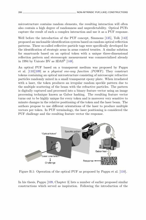
208 NON-INTRINSIC PUF(-LIKE) CONSTRUCTIONS
microstructure contains random elements, the resulting interaction will oftenalso contain a high degree of randomness and unpredictability. Optical PUFscapture the result of such a complex interaction and use it as a PUF response.
Well before the introduction of the PUF concept, Simmons [135], Tolk [142]proposed an unclonable identification system based on random optical reflectionpatterns. These so-called reflective particle tags were specifically developed forthe identification of strategic arms in arms control treaties. A similar solutionfor smartcards based on an optical token with a unique three-dimensionalreflection pattern and stereoscopic measurement was commercialized alreadyin 1994 by Unicate BV as 3DAS® [148].
An optical PUF based on a transparent medium was proposed by Pappuet al. [110][109] as a physical one-way function (POWF). They constructtokens containing an optical microstructure consisting of microscopic refractiveparticles randomly mixed in a small transparent epoxy plate. When irradiatedwith a laser, the token produces an irregular random speckle pattern due tothe multiple scattering of the beam with the refractive particles. The patternis digitally captured and processed into a binary feature vector using an imageprocessing technique known as Gabor hashing. The resulting feature vectorturns out to be highly unique for every token and is moreover very sensitive tominute changes in the relative positioning of the token and the laser beam. Theauthors propose to use different orientations of the laser to produce multiplevectors per token. In PUF terminology, the laser positioning is considered thePUF challenge and the resulting feature vector the response.
Figure B.1: Operation of the optical PUF as proposed by Pappu et al. [110].
In his thesis, Pappu [109, Chapter 3] lists a number of earlier proposed similarconstructions which served as inspiration. Following the introduction of the
OPTICS-BASED PUFS 209
optical PUF by Pappu et al. [110], the construction and security aspects ofoptical PUFs were further studied by Ignatenko et al. [61], Tuyls et al. [147],Škorić et al. [155]. A more practical integrated design of an optical PUF wasproposed by Gassend [45, Section 3.1.3] and also by Tuyls and Škorić [146], butno known implementations exist.
It is clear that the use of an optical PUF as proposed by Pappu et al. [110] israther laborious, requiring a large and expensive external measurement setupinvolving a laser and a tedious mechanical positioning system. The reliabilityof optical PUF responses is also relatively low in comparison to other proposals.However, in many ways this optical PUF construction can be considered as theprototype PUF. The physical functionality of the PUF is obvious, including awell-defined physical challenge and response, and all desirable PUF propertiesare achieved: tokens produced by the same process exhibit responses with ahigh level of uniqueness, yet responses can be relatively easily and reliablymeasured. These optical PUFs also have a very large challenge space, and itwas shown [147, 155] that predicting unseen responses for a particular token iscomputationally hard, even when an adversary has a lot of information aboutthe token. Pappu et al. [110] moreover claim that their PUF exhibits a degreeof one-wayness, hence their name physical one-way function, however this isnot one-wayness in the cryptographic sense. Ultimately, it was shown [110]that the tokens are tamper evident, i.e. a physical modification of the token,e.g. drilling a microscopic hole in it, alters its expected responses by nearly50%.
From the discussion in this chapter, it will be clear that not any single otherPUF construction achieves all these properties at once. In this respect, theoptical PUF can be considered a benchmark for PUF properties. The goal ofall following PUF proposals is to match the properties of an optical PUF asclosely as possible, but using a more integrated and practical construction.
B.1.2 Paper-based PUFs
The basic idea behind all paper-based PUFs is scanning the unique and randomfiber microstructure of regular or modified paper. As with the optical PUF,also for paper PUFs there were a number of early proposals, among othersby Bauder [11], Commission on Engineering and Technical Systems (CETS)[31], Simmons [135], well before the introduction of the PUF concept. Thesewere mainly considered as an anti-counterfeiting measure for currency notes.Buchanan et al. [22] propose a construction where the reflection of a focusedlaser beam of the irregular fiber structure of a paper document is used asfingerprint of that document to prevent forgery. A similar approach is used
210 NON-INTRINSIC PUF(-LIKE) CONSTRUCTIONS
by Bulens et al. [23], but they explicitly introduce ultraviolet fibers in thepaper during the manufacturing process. This makes it possible to measurethe paper structure using a regular desktop scanner instead of an expensivelaser. Bulens et al. [23] also introduce a method to strongly link the data onthe document with the paper by constructing a combined digital signature ofthe data and the paper’s fingerprint, which is printed on the document. A verysimilar concept was already proposed much earlier by Simmons [135] based onquadratic residues. Recently, Sharma et al. [132] proposed a technique whichenables to read unique microfeatures of regular paper using low cost commodityequipment. They also give a good overview of many earlier proposed similarconstructions. Yamakoshi et al. [156] describe a very similar concept usinginfrared scans of regular paper.
B.1.3 Phosphor PUF
Chong et al. [30] [63] propose to randomly blend small phosphor particles inthe material of a product or its cover. The resulting random phosphorentpattern can be detected using regular optical equipment and used as a uniquefingerprint to identify the product.
B.2 RF-based PUFs
B.2.1 RF-DNA
A construction called RF-DNA was proposed by Dejean and Kirovski [35]. Theyconstruct a small inexpensive token comparable to the one used for the opticalPUF, but now consisting of a flexible silicon sealant containing thin randomlyarranged copper wires. Instead of observing the scattering of light as withoptical PUFs, the near-field scattering of electromagnetic waves by the copperwires at other wavelengths is observed, notably in the 5 − 6 GHz band. Therandom scattering effects are measured by a prototype scanner consisting of amatrix of RF antennas.
B.2.2 LC PUF
An LC PUF as proposed by Guajardo et al. [51] is a small glass plate with ametal plate on each side, forming a capacitor, serially chained with a metal coilon the plate acting as an inductive component. Together they form a passive LC
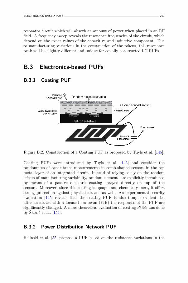
ELECTRONICS-BASED PUFS 211
resonator circuit which will absorb an amount of power when placed in an RFfield. A frequency sweep reveals the resonance frequencies of the circuit, whichdepend on the exact values of the capacitive and inductive component. Dueto manufacturing variations in the construction of the tokens, this resonancepeak will be slightly different and unique for equally constructed LC PUFs.
B.3 Electronics-based PUFs
B.3.1 Coating PUF
Figure B.2: Construction of a Coating PUF as proposed by Tuyls et al. [145].
Coating PUFs were introduced by Tuyls et al. [145] and consider therandomness of capacitance measurements in comb-shaped sensors in the topmetal layer of an integrated circuit. Instead of relying solely on the randomeffects of manufacturing variability, random elements are explicitly introducedby means of a passive dielectric coating sprayed directly on top of thesensors. Moreover, since this coating is opaque and chemically inert, it offersstrong protection against physical attacks as well. An experimental securityevaluation [145] reveals that the coating PUF is also tamper evident, i.e.after an attack with a focused ion beam (FIB) the responses of the PUF aresignificantly changed. A more theoretical evaluation of coating PUFs was doneby Škorić et al. [154].
B.3.2 Power Distribution Network PUF
Helinski et al. [55] propose a PUF based on the resistance variations in the
212 NON-INTRINSIC PUF(-LIKE) CONSTRUCTIONS
power grid of a silicon chip. Voltage drops and equivalent resistances in thepower distribution system are measured using external instruments and it isobserved that these electrical parameters are affected by random manufacturingvariability.
B.4 More Non-Intrinsic PUFs
B.4.1 CD-based PUF
Hammouri et al. [53] observed that the measured lengths of lands and pits ona regular compact disk (CD) exhibit a random deviation from their intendedlengths due to probabilistic variations in the manufacturing process. Moreover,this deviation is even large enough to be observed by monitoring the electricalsignal of the photodetector in a regular CD player. This was tested for a largenumber of CDs and locations on every CD. After an elaborate quantizationprocedure, an average intra-distance of µintra
P = 8% and an average inter-distanceof µinter
P = 54% on the obtained bit strings is achieved.
B.4.2 Acoustical PUF
Acoustical delay lines are components used to delay electrical signals. Theyconvert an alternating electrical signal into a mechanical vibration and back.Acoustical PUFs, as proposed by Vrijaldenhoven [153], are constructed byobserving the characteristic frequency spectrum of an acoustical delay line. Abit string is extracted by performing principal component analysis (PCA).
B.4.3 Magstripe-based PUF
The concept of a magnetic PUF was introduced by Indeck and Muller [62].They use the inherent uniqueness of the particle patterns in magnetic media,e.g. in magnetic swipe cards. Magstripe-based PUFs are used in a commercialapplication to prevent credit card fraud [94].
Bibliography
[1] 2012. English Wiktionary: -able.http://en.wiktionary.org/wiki/-able. pages 25
[2] 2012. Java™ Platform Standard Ed. 6: Interface Cloneable.http://docs.oracle.com/javase/6/docs/api/java/lang/Cloneable.html.pages 25
[3] 2012. Research on Physical Unclonble Functions (PUFs) at SES Lab,Virginia Tech.http://rijndael.ece.vt.edu/puf. pages 39
[4] 2012. The Complexity Zoo.http://qwiki.stanford.edu/index.php/Complexity_Zoo. pages 14
[5] 2012. The SHA-3 Zoo.http://ehash.iaik.tugraz.at/wiki/The_SHA-3_Zoo. pages 14
[6] 2012. UNIQUE: Foundations for Forgery-Resistant Security Hardware (EC-FP7: 238811).http://unique-security.eu/. pages 97
[7] Anderson, J. 2010. A PUF Design for Secure FPGA-based EmbeddedSystems. In Asia and South-Pacific Design Automation Conference – ASP-DAC 2010. 1–6. pages 40, 48
[8] Armknecht, F., Maes, R., Sadeghi, A.-R., Standaert, F.-X., andWachsmann, C. 2011. A Formal Foundation for the Security Features ofPhysical Functions. In IEEE Symposium on Security and Privacy – SP 2011.IEEE, 397–412. pages 11, 59, 77, 81
[9] Armknecht, F., Maes, R., Sadeghi, A.-R., Sunar, B., and Tuyls, P.2009. Memory Leakage-Resilient Encryption based on Physically UnclonableFunctions. In Advances in Cryptology – ASIACRYPT 2009. Lecture Notesin Computer Science (LNCS), vol. 5912. Springer, 685–702. pages 80, 199
213
214 BIBLIOGRAPHY
[10] Barker, E. and Kelsey, J. 2012. Recommendation for RandomNumber Generation Using Deterministic Random Bit Generators. NISTSpecial Publication 800-90Ahttp://csrc.nist.gov/publications/nistpubs/800-90A/SP800-90A.pdf.pages 171, 172
[11] Bauder, D. 1983. An Anti-Counterfeiting Concept for Currency Systems.Tech. Rep. PTK-11990, Sandia National Labs, Albuquerque, NM, US. pages209
[12] Beckmann, N. and Potkonjak, M. 2009. Hardware-Based Public-KeyCryptography with Public Physically Unclonable Functions. In InternationalWorkshop on Information Hiding – IH 2009. Lecture Notes in ComputerScience (LNCS), vol. 5806. Springer, 206–220. pages 55
[13] Berlekamp, E. 1965. On Decoding Binary Bose-Chadhuri-HocquenghemCodes. IEEE Transactions on Information Theory 11, 4, 577–579. pages 191
[14] Bogdanov, A., Knežević, M., Leander, G., Toz, D., Varici, K.,and Verbauwhede, I. 2011. SPONGENT: a Lightweight Hash Function.In Workshop on Cryptographic Hardware and Embedded Systems – CHES2011. Lecture Notes in Computer Science (LNCS), vol. 6917. Springer, 312–325. pages 160, 192
[15] Bolotnyy, L. and Robins, G. 2007. Physically Unclonable Function-Based Security and Privacy in RFID Systems. In IEEE InternationalConference on Pervasive Computing and Communications – PERCOM 2007.IEEE, 211–220. pages 152
[16] Boneh, D., DeMillo, R. A., and Lipton, R. J. 1997. On theImportance of Checking Cryptographic Protocols for Faults. In Advancesin Cryptology – EUROCRYPT 1997. Lecture Notes in Computer Science(LNCS), vol. 1233. Springer, 37–51. pages 7
[17] Bösch, C., Guajardo, J., Sadeghi, A.-R., Shokrollahi, J., andTuyls, P. 2008. Efficient Helper Data Key Extractor on FPGAs. InWorkshop on Cryptographic Hardware and Embedded Systems – CHES 2008.Lecture Notes in Computer Science (LNCS), vol. 5154. Springer, 181–197.pages 166, 179, 184
[18] Bose, R. C. and Ray-Chaudhuri, D. K. 1960. On A Class of ErrorCorrecting Binary Group Codes. Information and Control 3, 1, 68–79. pages159
[19] Boyen, X. 2004. Reusable Cryptographic Fuzzy Extractors. In ACMConference on Computer and Communications Security – CCS 2004. ACM,82–91. pages 159
BIBLIOGRAPHY 215
[20] Bringer, J., Chabanne, H., and Icart, T. 2009. On PhysicalObfuscation of Cryptographic Algorithms. In International Conferenceon Cryptology in India – INDOCRYPT 2009. Lecture Notes in ComputerScience (LNCS), vol. 5922. Springer, 88–103. pages 52
[21] Brzuska, C., Fischlin, M., Schröder, H., and Katzenbeisser,S. 2011. Physically Uncloneable Functions in the Universal CompositionFramework. In Advances in Cryptology – CRYPTO 2011. Lecture Notes inComputer Science (LNCS), vol. 6841. Springer, 51–70. pages 80
[22] Buchanan, J. D. R., Cowburn, R. P., Jausovec, A.-V., Petit, D.,Seem, P., Xiong, G., Atkinson, D., Fenton, K., Allwood, D. A., andBryan, M. T. 2005. Forgery: ‘Fingerprinting’ Documents and Packaging.Nature 436, 7050, 475. pages 209
[23] Bulens, P., Standaert, F.-X., and Quisquater, J.-J. 2010. Howto Strongly Link Data and its Medium: the Paper Case. IET InformationSecurity 4, 3, 125–136. pages 210
[24] Burr, A. 2001. Modulation and Coding for Wireless Communications.Pearson. pages 159
[25] Burton, H. 1971. Inversionless Decoding of Binary BCH codes. IEEETransactions on Information Theory 17, 4 (July), 464–466. pages 191
[26] Canetti, R. 2001. Universally Composable Security: A New Paradigmfor Cryptographic Protocols. In IEEE Symposium on Foundations ofComputer Science – FOCS 2001. IEEE, 136–145. pages 80
[27] Carter, J. L. and Wegman, M. N. 1977. Universal Classes of HashFunctions. In ACM Symposium on Theory of Computing – STOC 1977.ACM, 106–112. pages 170
[28] Chen, Q., Csaba, G., Lugli, P., Schlichtmann, U., and Ruhrmair,U. 2011. The Bistable Ring PUF: A New Architecture for Strong PhysicalUnclonable Functions. In IEEE International Symposium on Hardware-Oriented Security and Trust – HOST 2011. IEEE, 134–141. pages 47, 49,69
[29] Chien, R. 1964. Cyclic Decoding Procedures for Bose-Chaudhuri-Hocquenghem Codes. IEEE Transactions on Information Theory 10, 4, 357–363. pages 191
[30] Chong, C. N., Jiang, D., Zhang, J., and Guo, L. 2008. Anti-Counterfeiting with a Random Pattern. In International Conference onEmerging Security Information, Systems and Technologies – SECURWARE2008. IEEE, 146–153. pages 210
216 BIBLIOGRAPHY
[31] Commission on Engineering and Technical Systems (CETS).1993. Counterfeit Deterrent Features for the Next-Generation CurrencyDesign. The National Academic Press. Appendix E. pages 209
[32] Cortes, C. and Vapnik, V. 1995. Support-Vector Networks. MachineLearning 20, 3, 273–297. pages 128
[33] Cover, T. M. and Thomas, J. A. 2006. Elements of InformationTheory. Wiley. pages 204
[34] Daemen, J. and Rijmen, V. 2002. The Design of Rijndael. Springer.pages 41
[35] Dejean, G. and Kirovski, D. 2007. RF-DNA: Radio-FrequencyCertificates of Authenticity. In Workshop on Cryptographic Hardware andEmbedded Systems – CHES 2007. Lecture Notes in Computer Science(LNCS), vol. 4727. Springer, 346–363. pages 26, 210
[36] Devadas, S., Suh, E., Paral, S., Sowell, R., Ziola, T., andKhandelwal, V. 2008. Design and Implementation of PUF-Based“Unclonable” RFID ICs for Anti-Counterfeiting and Security Applications.In IEEE International Conference on RFID – RFID 2008. IEEE, 58–64.pages 150
[37] Diffie, W. and Hellman, M. E. 1976. New Directions in Cryptography.IEEE Transactions on Information Theory 22, 6, 644–654. pages 5
[38] Dodis, Y., Ostrovsky, R., Reyzin, L., and Smith, A. 2008. FuzzyExtractors: How to Generate Strong Keys from Biometrics and Other NoisyData. SIAM Journal on Computing 38, 1, 97–139. pages 82, 140, 154, 167,168, 169, 172, 173, 206
[39] Dodis, Y., Reyzin, L., and Smith, A. 2004. Fuzzy Extractors: How toGenerate Strong Keys from Biometrics and Other Noisy Data. In Advancesin Cryptology – EUROCRYPT 2004. Lecture Notes in Computer Science(LNCS), vol. 3027. Springer, 523–540. pages 82, 140, 154, 167, 172, 173
[40] Eastlake, D., Schiller, J., and Crocker, S. 2005.Randomness Requirements for Security. IETF RFC 4086http://www.ietf.org/rfc/rfc4086.txt. pages 171
[41] Ferguson, N. and Schneier, B. 2003. Practical Cryptography. Wiley.pages 172
[42] Fischer, V. and Drutarovský, M. 2002. True Random NumberGenerator Embedded in Reconfigurable Hardware. In Workshop on
BIBLIOGRAPHY 217
Cryptographic Hardware and Embedded Systems – CHES 2002. Lecture Notesin Computer Science (LNCS), vol. 2523. Springer, 415–430. pages 7
[43] Fujiwara, H., Yabuuchi, M., Nakano, H., Kawai, H., Nii, K., andArimoto, K. 2011. A Chip-ID Generating Circuit for Dependable LSI UsingRandom Address Errors on Embedded SRAM and On-chip Memory BIST.In Symposium on VLSI Circuits – VLSIC 2011. IEEE, 76–77. pages 49, 51
[44] Gallager, R. G. 1962. Low Density Parity-Check Codes. IRETransactions on Information Theory 8, 21–28. pages 176
[45] Gassend, B. 2003. Physical Random Functions. M.S. thesis,Massachusetts Institute of Technology (MIT), MA, USA. pages 36, 52, 209
[46] Gassend, B., Clarke, D., van Dijk, M., and Devadas, S. 2002a.Controlled Physical Random Functions. In Annual Computer SecurityApplications Conference – ACSAC 2002. IEEE. pages 53
[47] Gassend, B., Clarke, D., van Dijk, M., and Devadas, S. 2002b.Silicon Physical Random Functions. In ACM Conference on Computer andCommunications Security – CCS 2002. ACM, 148–160. pages xv, 24, 27, 36,37, 48, 78, 79, 150
[48] Gassend, B., Lim, D., Clarke, D., van Dijk, M., and Devadas,S. 2004. Identification and Authentication of Integrated Circuits: ResearchArticles. Concurrency and Computation: Practice and Experience 16, 11,1077–1098. pages 31, 32, 34, 48, 130
[49] Gray, F. 1947. Pulse Code Communication. US Patent No. 2,632,058.pages 109
[50] Guajardo, J., Kumar, S. S., Schrijen, G. J., and Tuyls, P. 2007.FPGA Intrinsic PUFs and Their Use for IP Protection. In Workshop onCryptographic Hardware and Embedded Systems – CHES 2007. Lecture Notesin Computer Science (LNCS), vol. 4727. Springer, 63–80. pages 27, 29, 44,48, 69, 79, 99, 103, 166
[51] Guajardo, J., Škorić, B., Tuyls, P., Kumar, S. S., Bel, T., Blom,A. H., and Schrijen, G.-J. 2009. Anti-Counterfeiting, Key Distribution,and Key Storage in an Ambient World via Physical Unclonable Functions.Information Systems Frontiers 11, 1, 19–41. pages 26, 210
[52] Gutmann, P. 2004. Cryptographic Security Architecture. Springer. pages171
218 BIBLIOGRAPHY
[53] Hammouri, G., Dana, A., and Sunar, B. 2009. CDs Have FingerprintsToo. In Workshop on Cryptographic Hardware and Embedded Systems –CHES 2009. Lecture Notes in Computer Science (LNCS), vol. 5747. Springer,348–362. pages 212
[54] Hammouri, G., Öztürk, E., Birand, B., and Sunar, B. 2008.Unclonable Lightweight Authentication Scheme. In International Conferenceon Information, Communications, and Signal Processing – ICICS 2008. 33–48. pages 35
[55] Helinski, R., Acharyya, D., and Plusquellic, J. 2009. A PhysicalUnclonable Function Defined Using Power Distribution System EquivalentResistance Variations. In Design Automation Conference – DAC 2009. ACM,676–681. pages 211
[56] Hocquenghem, A. 1960. Codes Correcteurs d’Erreurs. Chiffres 2, 147–156. pages 159
[57] Holcomb, D. E., Burleson, W. P., and Fu, K. 2007. Initial SRAMState as a Fingerprint and Source of True Random Numbers for RFID Tags.In Workshop on RFID Security and Privacy – RFIDSec 2007. pages 44
[58] Holcomb, D. E., Burleson, W. P., and Fu, K. 2009. Power-UpSRAM State as an Identifying Fingerprint and Source of True RandomNumbers. IEEE Transactions on Computers 58, 9, 1198–1210. pages 44,48
[59] Hopper, N. and Blum, M. 2000. A Secure Human-ComputerAuthentication Scheme. Tech. Rep. CMU-CS-00-139, School of ComputerScience, Carnegie Mellon University, Pittsburgh, PA, US. pages 35
[60] Hospodar, G., Maes, R., and Verbauwhede, I. 2012. Implicationsof Machine Learning Attacks on Arbiter PUF-based Challenge-ResponseAuthentication and Secure Key Generation. Tech. Rep. 2220, COSIC, KULeuven, Leuven, Belgium. (under submission). pages 128, 130
[61] Ignatenko, T., Schrijen, G.-J., Škorić, B., Tuyls, P., andWillems, F. M. J. 2006. Estimating the Secrecy Rate of PhysicalUncloneable Functions with the Context-Tree Weighting Method. In IEEEInternational Symposium on Information Theory – ISIT 2006. IEEE, 499–503. pages 209
[62] Indeck, R. S. and Muller, M. W. 1994. Method and Apparatus forFingerprinting Magnetic Media. US Patent No. 5,365,586. pages 212
BIBLIOGRAPHY 219
[63] Jiang, D. and Chong, C. N. 2008. Anti-Counterfeiting Using PhosphorPUF. In International Conference on Anti-counterfeiting, Security andIdentification – ASID 2008. 59–62. pages 210
[64] Juels, A. and Sudan, M. 2006. A Fuzzy Vault Scheme. Designs, Codesand Cryptography 38, 2 (Feb.), 237–257. pages 140
[65] Juels, A. and Wattenberg, M. 1999. A Fuzzy Commitment Scheme.In ACM Conference on Computer and Communications Security – CCS 1999.ACM, 28–36. pages 140
[66] Kalinsky, D. and Kalinsky, R. 2002. Introduction to Serial PeripheralInterface. EETimeshttp://www.eetimes.com/discussion/beginner-s-corner/4023908
/Introduction-to-Serial-Peripheral-Interface. pages 100
[67] Karakoyunlu, D. and Sunar, B. 2010. Differential Template Attackson PUF Enabled Cryptographic Devices. In IEEE International Workshopon Information Forensics and Security – WIFS 2010. IEEE, 1–6. pages 200
[68] Kardas, S., Akgun, M., Kiraz, M. S., and Demirci, H.2011. Cryptanalysis of Lightweight Mutual Authentication and OwnershipTransfer for RFID Systems. Workshop on Lightweight Security and Privacy:Devices, Protocols, and Applications – LightSec 2011 , 20–25. pages 152
[69] Katzenbeisser, S., Koçabas, U., van der Leest, V., Sadeghi,A.-R., Schrijen, G.-J., Schröder, H., and Wachsmann, C. 2011.Recyclable PUFs: Logically Reconfigurable PUFs. In Workshop onCryptographic Hardware and Embedded Systems – CHES 2011. Lecture Notesin Computer Science (LNCS), vol. 6917. Springer, 374–389. pages 54
[70] Kelsey, J., Schneier, B., and Ferguson, N. 1999. Yarrow-160: Noteson the Design and Analysis of the Yarrow Cryptographic PseudorandomNumber Generator. In International Workshop on Selected Areas inCryptography – SAC 1999. Lecture Notes in Computer Science (LNCS), vol.1758. Springer, 13–33. pages 171, 172
[71] Kerckhoffs, A. 1883. La Cryptographie Militaire. Journal des SciencesMilitaires IX, 5–83. pages 4
[72] Kim, I., Maiti, A., Nazhandali, L., Schaumont, P., Vivekraja, V.,and Zhang, H. 2010. From Statistics to Circuits: Foundations for FuturePhysical Unclonable Functions. In Towards Hardware-Intrinsic Security, A.-R. Sadeghi and D. Naccache, Eds. Information Security and Cryptography.Springer, 55–78. pages 40
220 BIBLIOGRAPHY
[73] Kocher, P. C. 1996. Timing Attacks on Implementations of Diffie-Hellman, RSA, DSS, and Other Systems. In Advances in Cryptology –CRYPTO 1996. Lecture Notes in Computer Science (LNCS), vol. 1109.Springer, 104–113. pages 7
[74] Kocher, P. C., Jaffe, J., and Jun, B. 1999. Differential PowerAnalysis. In Advances in Cryptology – CRYPTO 1999. Lecture Notes inComputer Science (LNCS), vol. 1666. Springer, 388–397. pages 7
[75] Krishna, A., Narasimhan, S., Wang, X., and Bhunia, S. 2011.MECCA: A Robust Low-Overhead PUF Using Embedded Memory Array.In Workshop on Cryptographic Hardware and Embedded Systems – CHES2011. Lecture Notes in Computer Science (LNCS), vol. 6917. Springer, 407–420. pages 51
[76] Kulseng, L., Yu, Z., Wei, Y., and Guan, Y. 2010. LightweightMutual Authentication and Ownership Transfer for RFID Systems. In IEEEInternational Conference on Computer Communications – INFOCOM 2010.IEEE, 1–5. pages 152
[77] Kumar, S., Guajardo, J., Maes, R., Schrijen, G.-J., and Tuyls,P. 2008. Extended abstract: The Butterfly PUF Protecting IP on EveryFPGA. In IEEE International Symposium on Hardware-Oriented Securityand Trust – HOST 2008. IEEE, 67–70. pages 10, 46, 49, 69
[78] Kursawe, K., Sadeghi, A.-R., Schellekens, D., Tuyls, P., andŠkorić, B. 2009. Reconfigurable Physical Unclonable Functions – EnablingTechnology for Tamper-Resistant Storage. In IEEE International Symposiumon Hardware-Oriented Security and Trust – HOST 2009. IEEE, 22–29. pages53, 54
[79] Lao, Y. and Parhi, K. 2011. Reconfigurable Architectures for SiliconPhysical Unclonable Functions. In IEEE International Conference onElectro/Information Technology – EIT 2011. IEEE, 1–7. pages 35
[80] Lee, J. W., Lim, D., Gassend, B., Suh, G. E., van Dijk, M., andDevadas, S. 2004. A Technique to Build a Secret Key in Integrated Circuitsfor Identification and Authentication Application. In Symposium on VLSICircuits – VLSIC 2004. 176–159. pages xv, 31, 32, 33, 34, 48, 68, 78, 99, 102,128
[81] Lehmer, D. H. 1960. Teaching Combinatorial Tricks to a Computer.In Symposium on Applied Mathematics and Combinatorial Analysis. AMS,179–193. pages 109
BIBLIOGRAPHY 221
[82] Lenstra, A. K., Hughes, J. P., Augier, M., Bos, J. W., Kleinjung,T., and Wachter, C. 2012. Ron was Wrong, Whit is Right. CryptologyePrint Archive, Report 2012/064. pages 7, 165
[83] Lim, D. 2004. Extracting Secret Keys from Integrated Circuits. M.S.thesis, Massachusetts Institute of Technology (MIT), MA, USA. pages 31,32, 34
[84] Lim, D., Lee, J. W., Gassend, B., Suh, G. E., van Dijk, M., andDevadas, S. 2005. Extracting Secret Keys from Integrated Circuits. IEEETransactions on Very Large Scale Integration (VLSI) Systems 13, 10, 1200–1205. pages 48
[85] Lin, L., Holcomb, D., Krishnappa, D. K., Shabadi, P., andBurleson, W. 2010. Low-Power Sub-Threshold Design of Secure PhysicalUnclonable Functions. In ACM/IEEE International Symposium on Lowpower Electronics and Design – ISLPED 2010. ACM, 43–48. pages 32
[86] Linnartz, J.-P. and Tuyls, P. 2003. New Shielding Functionsto Enhance Privacy and Prevent Misuse of Biometric Templates. InInternational Conference on Audio- and Video-based Biometric PersonAuthentication – AVBPA 2003. Lecture Notes in Computer Science (LNCS),vol. 2688. Springer, 393–402. pages 173
[87] Lofstrom, K., Daasch, W. R., and Taylor, D. 2000. IC IdentificationCircuit Using Device Mismatch. In IEEE International Solid-State CircuitsConference – ISSCC 2000. IEEE, 372–373. pages 49, 50
[88] Maes, R., Rozic, V., Verbauwhede, I., Koeberl, P., van der Sluis,E., and van der Leest, V. 2012. Experimental Evaluation of PhysicallyUnclonable Functions in 65 nm CMOS. In European Solid-State CircuitsConference – ESSCIRC 2012. pages 11
[89] Maes, R., Tuyls, P., and Verbauwhede, I. 2008. Intrinsic PUFs fromFlip-flops on Reconfigurable Devices. In Benelux Workshop on Informationand System Security – WISSec 2008. pages 10, 46, 49, 69, 99
[90] Maes, R., Tuyls, P., and Verbauwhede, I. 2009a. Low-OverheadImplementation of a Soft Decision Helper Data Algorithm for SRAM PUFs.In Workshop on Cryptographic Hardware and Embedded Systems – CHES2009. Lecture Notes in Computer Science (LNCS), vol. 5747. Springer, 332–347. pages 11, 167, 177, 179
[91] Maes, R., Tuyls, P., and Verbauwhede, I. 2009b. Soft DecisionHelper Data Algorithm for SRAM PUFs. In IEEE International Symposiumon Information Theory – ISIT 2009. IEEE, 2101–2105. pages 167, 175
222 BIBLIOGRAPHY
[92] Maes, R., Van Herrewege, A., and Verbauwhede, I. 2012. PUFKY:A Fully Functional PUF-based Cryptographic Key Generator. In Workshopon Cryptographic Hardware and Embedded Systems – CHES 2012. LectureNotes in Computer Science (LNCS), vol. 7428. Springer. pages 11, 109, 186,191
[93] Maes, R. and Verbauwhede, I. 2010. Physically Unclonable Functions:A Study on the State of the Art and Future Research Directions. InTowards Hardware-Intrinsic Security, A.-R. Sadeghi and D. Naccache, Eds.Information Security and Cryptography. Springer, 3–37. pages 10, 11, 15, 59
[94] MagneTek(R). MagnePrint(R). http://www.magneprint.com/. pages212
[95] Maiti, A., Casarona, J., McHale, L., and Schaumont, P. 2010. ALarge Scale Characterization of RO-PUF. IEEE International Symposiumon Hardware-Oriented Security and Trust – HOST 2010 , 94–99. pages 39,48, 190
[96] Maiti, A., Kim, I., and Schaumont, P. 2012. A Robust PhysicalUnclonable Function With Enhanced Challenge-Response Set. IEEETransactions on Information Forensics and Security 7, 1 (feb.), 333–345.pages 40, 48, 69
[97] Maiti, A. and Schaumont, P. 2009. Improving the Quality of a PhysicalUnclonable Function Using Configurable Ring Oscillators. In InternationalConference on Field Programmable Logic and Applications – FPL 2009. 703–707. pages 39
[98] Maiti, A. and Schaumont, P. 2011. Improved Ring Oscillator PUF: AnFPGA-friendly Secure Primitive. Journal of Cryptology 24, 375–397. pages39, 48
[99] Majzoobi, M., Koushanfar, F., and Potkonjak, M. 2008. TestingTechniques for Hardware Security. In IEEE International Test Conference –ITC 2008. IEEE, 1–10. pages 34
[100] Majzoobi, M., Koushanfar, F., and Potkonjak, M. 2009.Techniques for Design and Implementation of Secure Reconfigurable PUFs.ACM Transactions on Reconfigurable Technology and Systems 2, 1, 1–33.pages 35, 69, 108
[101] Massey, J. 1969. Shift-Register Synthesis and BCH Decoding. IEEETransactions on Information Theory 15, 1, 122–127. pages 191
[102] Menezes, A. J., Vanstone, S. A., and Oorschot, P. C. V. 1996.Handbook of Applied Cryptography. CRC Press. pages 5, 136, 153
BIBLIOGRAPHY 223
[103] Merli, D., Schuster, D., Stumpf, F., and Sigl, G. 2011. Side-Channel Analysis of PUFs and Fuzzy Extractors. In International Conferenceon Trust and Trustworthy Computing – TRUST 2011. Lecture Notes inComputer Science (LNCS), vol. 6740. Springer, 33–47. pages 200
[104] Mitchell, T. M. 1997. Machine learning. McGraw-Hill. pages 128
[105] Morozov, S., Maiti, A., and Schaumont, P. 2010. An Analysis ofDelay Based PUF Implementations on FPGA. In International Workshop onApplied Reconfigurable Computing – ARC 2010. Lecture Notes in ComputerScience (LNCS), vol. 5992. Springer, 382–387. pages 33
[106] Nisan, N. and Zuckerman, D. 1996. Randomness is Linear in Space.Journal of Computer and System Sciences 52, 1, 43–52. pages 170
[107] Öztürk, E., Hammouri, G., and Sunar, B. 2008a. PhysicalUnclonable Function with Tristate Buffers. In IEEE InternationalSymposium on Circuits and Systems – ISCAS 2008. IEEE, 3194–3197. pages35
[108] Öztürk, E., Hammouri, G., and Sunar, B. 2008b. Towards RobustLow Cost Authentication for Pervasive Devices. In IEEE InternationalConference on Pervasive Computing and Communications – PERCOM 2008.IEEE, 170–178. pages 35
[109] Pappu, R. S. 2001. Physical One-Way Functions. Ph.D. thesis,Massachusetts Institute of Technology (MIT), MA, USA. pages 24, 29, 58,66, 74, 76, 78, 208
[110] Pappu, R. S., Recht, B., Taylor, J., and Gershenfeld, N. 2002.Physical One-Way Functions. Science 297, 2026–2030. pages xvi, 29, 68, 93,208, 209
[111] Puntin, D., Stanzione, S., and Iannaccone, G. 2008. CMOSUnclonable System for Secure Authentication Based on Device Variability. InEuropean Solid-State Circuits Conference – ESSCIRC 2008. 130–133. pages50
[112] Quisquater, J.-J. and Samyde, D. 2001. ElectroMagnetic Analysis(EMA): Measures and Counter-Measures for Smart Cards. In InternationalConference on Research in Smart Cards – E-SMART 2001. Lecture Notes inComputer Science (LNCS), vol. 2140. Springer-Verlag, 200–210. pages 7
[113] Ranasinghe, D. C., Engels, D. W., and Cole, P. H. 2004. Securityand Privacy: Modest Proposals for Low-Cost RFID Systems. In Auto-IDLabs Research Workshop 2004. pages 150
224 BIBLIOGRAPHY
[114] Rényi, A. 1960. On Measures of Information and Entropy. In BerkeleySymposium on Mathematics, Statistics and Probability 1960. 547–561. pages206
[115] Rivest, R. L., Shamir, A., and Adleman, L. 1978. AMethod for Obtaining Digital Signatures and Public-Key Cryptosystems.Communications of the ACM 21, 2, 120–126. pages 5
[116] Rührmair, U. 2009. SIMPL Systems: On a Public Key Variant ofPhysical Unclonable Functions. Cryptology ePrint Archive, Report 2009/255.pages 55
[117] Rührmair, U. 2011. SIMPL Systems, or: Can We Design CryptographicHardware without Secret Key Information? In Conference on CurrentTrends in Theory and Practice of Computer Science – SOFSEM 2011.Lecture Notes in Computer Science (LNCS), vol. 6543. Springer, 26–45.pages 74
[118] Rührmair, U., Busch, H., and Katzenbeisser, S. 2010. StrongPUFs: Models, Constructions, and Security Proofs. In Towards Hardware-Intrinsic Security, A.-R. Sadeghi and D. Naccache, Eds. Information Securityand Cryptography. Springer, 79–96. pages 29
[119] Rührmair, U., Chen, Q., Lugli, P., Schlichtmann, U., andMartin Stutzmann, G. C. 2009. Towards Electrical, IntegratedImplementations of SIMPL Systems. Cryptology ePrint Archive, Report2009/278. pages 55
[120] Rührmair, U., Jaeger, C., and Algasinger, M. 2011. An Attack onPUF-Based Session Key Exchange and a Hardware-Based Countermeasure:Erasable PUFs. In International Conference on Financial Cryptography andData Security – FC 2012. Lecture Notes in Computer Science (LNCS), vol.7035. Springer, 190–204. pages 54
[121] Rührmair, U., Jaeger, C., Bator, M., Stutzmann, M., Lugli, P.,and Csaba, G. 2011. Applications of High-Capacity Crossbar Memories inCryptography. IEEE Transactions on Nanotechnology 10, 3, 489–498. pages51
[122] Rührmair, U., Jaeger, C., Hilgers, C., Algasinger, M., Csaba,G., and Stutzmann, M. 2010. Security Applications of Diodes with UniqueCurrent-Voltage Characteristics. In International Conference on FinancialCryptography and Data Security – FC 2010. Lecture Notes in ComputerScience (LNCS), vol. 6052. Springer, 328–335. pages 51
BIBLIOGRAPHY 225
[123] Rührmair, U., Sehnke, F., Sölter, J., Dror, G., Devadas, S.,and Schmidhuber, J. 2010a. Modeling Attacks on Physical UnclonableFunctions. In ACM Conference on Computer and Communications Security– CCS 2010. ACM, 237–249. pages 34, 35, 128, 130
[124] Rührmair, U., Sehnke, F., Sölter, J., Dror, G., Devadas, S.,and Schmidhuber, J. 2010b. Modeling Attacks on Physical UnclonableFunctions. Cryptology ePrint Archive, Report 2010/251. pages 78
[125] Rührmair, U., Sölter, J., and Sehnke, F. 2009. On the Foundationsof Physical Unclonable Functions. Cryptology ePrint Archive, Report2009/277. pages 77, 78, 79
[126] Schindler, W. and Killmann, W. 2002. Evaluation Criteria for True(Physical) Random Number Generators Used in Cryptographic Applications.In Workshop on Cryptographic Hardware and Embedded Systems – CHES2002. Lecture Notes in Computer Science (LNCS), vol. 2523. Springer, 431–449. pages 7
[127] Schnabl, G. and Bossert, M. 1995. Soft-Decision Decoding ofReed-Muller Codes as Generalized Multiple Concatenated Codes. IEEETransactions on Information Theory 41, 1, 304–308. pages 176, 177
[128] Schrijen, G.-J. and van der Leest, V. 2012. Comparative Analysisof SRAM Memories Used as PUF Primitives. In Design, Automation andTest in Europe – DATE 2012. 1319–1324. pages 44
[129] Sedgewick, R. 1977. Permutation Generation Methods. ACMComputing Surveys 9, 2, 137–164. pages 109
[130] Selimis, G. N., Konijnenburg, M., Ashouei, M., Huisken, J.,de Groot, H., van der Leest, V., Schrijen, G. J., van Hulst, M.,and Tuyls, P. 2011. Evaluation of 90nm 6T-SRAM as Physical UnclonableFunction for Secure Key Generation in Wireless Sensor Nodes. In IEEEInternational Symposium on Circuits and Systems – ISCAS 2011. IEEE,567–570. pages 44, 48, 49
[131] Shannon, C. E. 1948. A Mathematical Theory of Communication. BellSystems Technical Journal 27, 623–656. pages 204
[132] Sharma, A., Subramanian, L., and Brewer, E. A. 2011.PaperSpeckle: Microscopic Fingerprinting of Paper. In ACM Conference onComputer and Communications Security – CCS 2011. ACM, 99–110. pages210
226 BIBLIOGRAPHY
[133] Shimizu, K., Suzuki, D., and Kasuya, T. 2012. Glitch PUF:Extracting Information from Usually Unwanted Glitches. IEICE Trans-actions on Fundamentals of Electronics, Communications and ComputerSciences E95.A, 1, 223–233. pages xv, 41, 42, 48, 69
[134] Silverman, R. and Balser, M. 1954. Coding for Constant-Data-RateSystems-Part I. A New Error-Correcting Code. Proceedings of the IRE 42, 9,1428–1435. pages 176
[135] Simmons, G. 1991. Identification of Data, Devices, Documents andIndividuals. In IEEE International Carnahan Conference on SecurityTechnology – ICCST 1991. IEEE, 197–218. pages 208, 209, 210
[136] Simons, P., van der Sluis, E., and van der Leest, V. 2012.Buskeeper PUFs, a Promising Alternative to D Flip-Flop PUFs. IEEEInternational Symposium on Hardware-Oriented Security and Trust – HOST2012 , 7–12. pages 47, 69, 99, 100
[137] Su, Y., Holleman, J., and Otis, B. 2007. A 1.6pJ/bit 96% StableChip-ID Generating Circuit using Process Variations. In IEEE InternationalSolid-State Circuits Conference – ISSCC 2007. IEEE, 406–611. pages 45, 49,69, 99
[138] Suh, G. E. and Devadas, S. 2007. Physical Unclonable Functions forDevice Authentication and Secret Key Generation. In Design AutomationConference – DAC 2007. ACM, 9–14. pages xv, 37, 38, 39, 48, 69, 99, 103,109
[139] Suzuki, D. and Shimizu, K. 2010. The Glitch PUF: A New Delay-PUF Architecture Exploiting Glitch Shapes. In Workshop on CryptographicHardware and Embedded Systems – CHES 2010. Lecture Notes in ComputerScience (LNCS), vol. 6225. Springer, 366–382. pages 41
[140] Tarnovsky, C. 2010. Deconstructing a ‘Secure’ Processor. Talk atBlack Hat Federal 2010http://www.blackhat.com/presentations/bh-dc-10
/Tarnovsky_Chris/BlackHat-DC-2010-Tarnovsky-DASP-slides.pdf.pages 7, 166
[141] Tiri, K., Hwang, D., Hodjat, A., Lai, B., Yang, S., Schaumont,P., and Verbauwhede, I. 2005. Prototype IC with WDDL and DifferentialRouting - DPA Resistance Assessment. In Workshop on CryptographicHardware and Embedded Systems – CHES 2005. Lecture Notes in ComputerScience (LNCS), vol. 3659. Springer, 354–365. pages 8
BIBLIOGRAPHY 227
[142] Tolk, K. 1992. Reflective Particle Technology for Identification ofCritical Components. Tech. Rep. SAND-92-1676C, Sandia National Labs,Albuquerque, NM, US. pages 208
[143] Torrance, R. and James, D. 2009. The State-of-the-Art in ICReverse Engineering. In Workshop on Cryptographic Hardware and EmbeddedSystems – CHES 2009. Lecture Notes in Computer Science (LNCS), vol. 5747.Springer, 363–381. pages 7, 166
[144] Tuyls, P. and Batina, L. 2006. RFID-Tags for Anti-Counterfeiting. InTopics in Cryptology: Cryptographers’ Track of the RSA Conference – CT-RSA 2006. Lecture Notes in Computer Science (LNCS), vol. 3860. Springer,115–131. pages 166
[145] Tuyls, P., Schrijen, G.-J., Škorić, B., van Geloven, J.,Verhaegh, N., and Wolters, R. 2006. Read-Proof Hardware fromProtective Coatings. In Workshop on Cryptographic Hardware and EmbeddedSystems – CHES 2006. Lecture Notes in Computer Science (LNCS), vol. 4249.Springer, 369–383. pages xvi, 29, 68, 74, 211
[146] Tuyls, P. and Škorić, B. 2006. Physical Unclonable Functions forEnhanced Security of Tokens and Tags. In Information Security SolutionsEurope – ISSE 2006. Vieweg, 30–37. pages 209
[147] Tuyls, P., Škorić, B., Stallinga, S., Akkermans, A. H. M.,and Ophey, W. 2005. Information-Theoretic Security Analysis ofPhysical Uncloneable Functions. In International Conference on FinancialCryptography and Data Security – FC 2005. Lecture Notes in ComputerScience (LNCS), vol. 3570. Springer, 141–155. pages 73, 74, 209
[148] Unicate BV. 1999. Guaranteeing Identity andSecure Payments – The Foundation for eCommerce.http://www.andreae.com/Unicate/emerge.pdf. pages 208
[149] van der Leest, V., Schrijen, G.-J., Handschuh, H., and Tuyls,P. 2010. Hardware Intrinsic Security from D Flip-flops. In ACM Workshopon Scalable Trusted Computing – STC 2010. ACM, 53–62. pages 46, 49
[150] Van Herrewege, A., Katzenbeisser, S., Maes, R., Peeters, R.,Sadeghi, A.-R., Verbauwhede, I., , and Wachsmann, C. 2012. ReverseFuzzy Extractors: Enabling Lightweight Mutual Authentication for PUF-enabled RFIDs. In International Conference on Financial Cryptography andData Security – FC 2012. Lecture Notes in Computer Science (LNCS), vol.7397. Springer. pages 11, 154, 155, 157, 158, 160
228 BIBLIOGRAPHY
[151] Viterbi, A. 1967. Error Bounds for Convolutional Codes and anAsymptotically Optimum Decoding Algorithm. IEEE Transactions onInformation Theory 13, 2, 260–269. pages 176
[152] von Neumann, J. 1951. Various Techniques Used in Connection withRandom Digits. Journal of Research of the National Bureau of Standards 12,36–38. pages 46
[153] Vrijaldenhoven, S. 2005. Acoustical Physical Uncloneable Functions.M.S. thesis, Technische Universiteit Eindhoven, the Netherlands. pages 212
[154] Škorić, B., Maubach, S., Kevenaar, T., and Tuyls, P. 2006.Information-Theoretic Analysis of Capacitive Physical Unclonable Functions.Journal of Applied Physics 100, 2. pages 211
[155] Škorić, B., Tuyls, P., and Ophey, W. 2005. Robust Key Extractionfrom Physical Uncloneable Functions. In International Conference onApplied Cryptography and Network Security – ACNS 2005. Lecture Notesin Computer Science (LNCS), vol. 3531. Springer, 407–422. pages 73, 74,209
[156] Yamakoshi, M., Tanaka, J., Furuie, M., Hirabayashi, M.,and Matsumoto, T. 2008. Individuality Evaluation for Paper BasedArtifact-Metrics Using Transmitted Light Image. In Security, Forensics,Steganography, and Watermarking of Multimedia Contents X. ConferenceSeries of the Society of Photo-Optical Instrumentation Engineers (SPIE, vol.6819. pages 210
[157] Yamamoto, D., Sakiyama, K., Iwamoto, M., Ohta, K., Ochiai,T., Takenaka, M., and Itoh, K. 2011. Uniqueness Enhancement of PUFResponses Based on the Locations of Random Outputting RS Latches. InWorkshop on Cryptographic Hardware and Embedded Systems – CHES 2011.Lecture Notes in Computer Science (LNCS), vol. 6917. Springer, 390–406.pages 46
[158] Yin, C.-E. D. and Qu, G. 2010. LISA: Maximizing RO PUF’sSecret Extraction. In IEEE International Symposium on Hardware-OrientedSecurity and Trust – HOST 2010. IEEE, 100 –105. pages 39, 109
[159] Yu, M.-D. M., M’Raihi, D., Sowell, R., and Devadas, S. 2011.Lightweight and Secure PUF Key Storage Using Limits of Machine Learning.In Workshop on Cryptographic Hardware and Embedded Systems – CHES2011. Lecture Notes in Computer Science (LNCS), vol. 6917. Springer, 358–373. pages 166
Curriculum Vitae
Roel Maes was born on September 19, 1984 in Lommel, Belgium. Hereceived the Master’s degree in Electrical Engineering (Multimedia and SignalProcessing) from the University of Leuven (KU Leuven), Belgium in July 2007.He was a laureate for the Master thesis awards of the Royal Engineering Society(KVIV) with his thesis on physically unclonable functions in 2007.
In September 2007, he joined the COSIC research group at the department ofElectrical Engineering (ESAT) of KU Leuven. His PhD research was sponsoredby a four year fellowship from the Agency for Innovation by Science andTechnology in Flanders (IWT).
From August till September 2007, he was an intern in the Information andSystems Security group at Philips Research in Eindhoven, the Netherlands.From May till August 2011, he was a graduate technical intern in the SecurityResearch Lab at Intel Labs in Hillsboro (Portland), Oregon, US.
229

List of Publications
Journal Papers
1. Maes, R., Schellekens, D., and Verbauwhede, I. 2012. A Pay-per-Use Licensing Scheme for Hardware IP Cores in Recent SRAMFPGAs. IEEE Transactions on Information Forensics and Security 71, 98–108
Book Chapters
2. Maes, R., Verbauwhede, I. 2010. Physically Unclonable Functions:A Study on the State of the Art and Future Research Directions. InTowards Hardware-Intrinsic Security, A.-R. Sadeghi and D. Naccache,Eds. Information Security and Cryptography. Springer, 3–37.
3. Knežević, M., Batina, L., De Mulder, E., Fan, J., Gierlichs, B.,Lee, Y.K., Maes, R., and Verbauwhede, I. 2010 & 2012. SignalProcessing for Cryptography and Security Applications. In Handbook ofSignal Processing Systems (1st & 2nd Edition), S.S. Bhattacharyya, E.F.Deprettere, R. Leupers and J. Takala, Eds. Springer, 161–177.
4. Maes, R. and Tuyls, P. 2010. Process Variations for Security:PUFs. In Secure Integrated Circuits and Systems, I. Verbauwhede, Ed.Integrated Circuits and Systems. Springer, 125–143.
International Conferences: Lecture Notes in Computer Science
5. Maes, R., Van Herrewege, A., and Verbauwhede, I. 2012.PUFKY: A Fully Functional PUF-based Cryptographic Key Generator.In Workshop on Cryptographic Hardware and Embedded Systems – CHES2012. Lecture Notes in Computer Science (LNCS), vol. 7428. Springer.
231
232 LIST OF PUBLICATIONS
6. Van Herrewege, A., Katzenbeisser, S., Maes, R., Peeters, R.,Sadeghi, A.-R., Verbauwhede, I., and Wachsmann, C. 2012.Reverse Fuzzy Extractors: Enabling Lightweight Mutual Authenticationfor PUF-enabled RFIDs. In International Conference on FinancialCryptography and Data Security – FC 2012. Lecture Notes in ComputerScience (LNCS), vol. 7397. Springer.
7. Koeberl, P., Li, J., Maes, R., Rajan, A., Vishik, C., and Wójcik,M. 2011. Evaluation of a PUF Device Authentication Scheme on aDiscrete 0.13um SRAM. In International Conference on Trusted Systems– INTRUST 2011. Lecture Notes in Computer Science (LNCS), vol. 7222.Springer, 271–288.
8. Armknecht, F., Maes, R., Sadeghi, A.-R., Sunar, B., and Tuyls,P. 2009. Memory Leakage-Resilient Encryption based on PhysicallyUnclonable Functions. In Advances in Cryptology – ASIACRYPT 2009.Lecture Notes in Computer Science (LNCS), vol. 5912. Springer, 685–702.
9. Maes, R., Tuyls, P., and Verbauwhede, I. 2009. Low-OverheadImplementation of a Soft Decision Helper Data Algorithm for SRAMPUFs. In Workshop on Cryptographic Hardware and Embedded Systems– CHES 2009. Lecture Notes in Computer Science (LNCS), vol. 5747.Springer, 332–347.
International Conferences: IEEE, ACM, . . .
10. Maes, R., Rožić, V., Verbauwhede, I., Koeberl, P., van derSluis, E., and van der Leest, V. 2012. Experimental Evaluationof Physically Unclonable Functions in 65 nm CMOS. In European Solid-State Circuits Conference – ESSCIRC 2012.
11. Armknecht, F., Maes, R., Sadeghi, A.-R., Standaert, F.-X., andWachsmann, C. 2011. A Formal Foundation for the Security Featuresof Physical Functions. In IEEE Symposium on Security and Privacy –SP 2011. IEEE, 397–412.
12. Verbauwhede, I., Maes, R. 2011. Manufacturing Variability as anUnclonable Device Identifier. In ACM Great Lakes Symposium on VLSI– GLSVLSI 2011. ACM, 455–460.
13. Maes, R., Tuyls, P., and Verbauwhede, I. 2009. Soft DecisionHelper Data Algorithm for SRAM PUFs. In IEEE InternationalSymposium on Information Theory – ISIT 2009. IEEE, 2101–2105.
LIST OF PUBLICATIONS 233
14. Fan, J., Knežević, M., Karaklajić, D., Maes, R., Rožić, V.,Batina, L., and Verbauwhede, I. 2009. FPGA-based TestingStrategy for Cryptographic Chips. In IEEE International On-LineTesting Symposium – IOLTS 2009. IEEE, 189–191.
15. Maes, R., Schellekens, D., Tuyls, P., and Verbauwhede, I.2009. Analysis and Design of Active IC Metering Schemes. In IEEEInternational Symposium on Hardware-Oriented Security and Trust –HOST 2009. IEEE, 74–81.
16. Kumar, S., Guajardo, J., Maes, R., Schrijen, G.-J., and Tuyls,P. 2008. Extended abstract: The Butterfly PUF Protecting IP onEvery FPGA. In IEEE International Symposium on Hardware-OrientedSecurity and Trust – HOST 2008. IEEE, 67–70.
Peer-Reviewed Workshop Presentations and Posters
17. Maes, R., Verbauwhede, I. 2010. A Discussion on the Propertiesof Physically Unclonable Functions. In Workshop on Security Hardware2008.
18. Armknecht, F., Maes, R., Sadeghi, A.-R., Sunar, B., and Tuyls,P. 2010. Memory Leakage-Resilient Encryption based on PhysicallyUnclonable Functions. In Workshop on Secure Components and SystemIdentification – SECSI 2010.
19. Armknecht, F., Maes, R., Sadeghi, A.-R., Sunar, B., and Tuyls,P. 2009. PUF-PRFs: A New Tamper-Resilient Cryptographic Primitive.In Poster Session, Advances in Cryptology – EUROCRYPT 2009.
20. Armknecht, F., Maes, R., Sadeghi, A.-R., Sunar, B., and Tuyls,P. 2008. Physically Unclonable Pseudorandom Functions. In BeneluxWorkshop on Information and System Security – WISSec 2008.
21. Maes, R., Tuyls, P., and Verbauwhede, I. 2008. Intrinsic PUFsfrom Flip-flops on Reconfigurable Devices. In Benelux Workshop onInformation and System Security – WISSec 2008.
22. Maes, R., Tuyls, P., and Verbauwhede, I. 2008. StatisticalAnalysis of Silicon PUF Responses for Device Identification. In Workshopon Secure Components and System Identification – SECSI 2008.

234 LIST OF PUBLICATIONS
Other
23. Hospodar, G., Maes, R., and Verbauwhede, I. 2012. Implicationsof Machine Learning Attacks on Arbiter PUF-based Challenge-ResponseAuthentication and Secure Key Generation. COSIC Tech. Rep.2220, University of Leuven (KU Leuven), Leuven, Belgium. (undersubmission).
24. Maes, R. 2009. Veiligheid uit de “biometrie” van chips. In HetIngenieursblad 78 1
25. Maes, R. 2007. Sleutelextractie van een Silicon-PUF op FPGA. M.S.thesis, University of Leuven (KU Leuven), Leuven, Belgium.


Arenberg Doctoral School of Science, Engineering & Technology
Faculty of Engineering
Department of Electrical Engineering (ESAT)
Computer Security and Industrial Cryptography (COSIC)
Kasteelpark Arenberg 10 box 2446
B-3001 Heverlee