Synthesis and spectroscopic studies of some imines derived from
Upload
nguyendangCategory
view
231download
0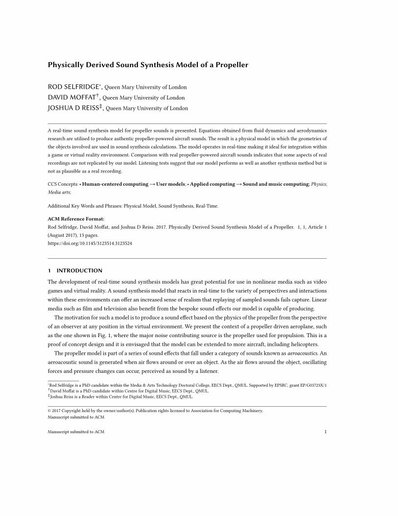
Physically Derived Sound Synthesis Model of a Propeller
ROD SELFRIDGE∗, Queen Mary University of London
DAVID MOFFAT†, Queen Mary University of London
JOSHUA D REISS‡, Queen Mary University of London
A real-time sound synthesis model for propeller sounds is presented. Equations obtained from fluid dynamics and aerodynamicsresearch are utilised to produce authentic propeller-powered aircraft sounds. The result is a physical model in which the geometries ofthe objects involved are used in sound synthesis calculations. The model operates in real-time making it ideal for integration withina game or virtual reality environment. Comparison with real propeller-powered aircraft sounds indicates that some aspects of realrecordings are not replicated by our model. Listening tests suggest that our model performs as well as another synthesis method but isnot as plausible as a real recording.
CCS Concepts: •Human-centered computing→Usermodels; •Applied computing→ Sound andmusic computing; Physics;Media arts;
Additional Key Words and Phrases: Physical Model, Sound Synthesis, Real-Time.
ACM Reference Format:Rod Selfridge, David Moffat, and Joshua D Reiss. 2017. Physically Derived Sound Synthesis Model of a Propeller. 1, 1, Article 1(August 2017), 13 pages.https://doi.org/10.1145/3123514.3123524
1 INTRODUCTION
The development of real-time sound synthesis models has great potential for use in nonlinear media such as videogames and virtual reality. A sound synthesis model that reacts in real-time to the variety of perspectives and interactionswithin these environments can offer an increased sense of realism that replaying of sampled sounds fails capture. Linearmedia such as film and television also benefit from the bespoke sound effects our model is capable of producing.
The motivation for such a model is to produce a sound effect based on the physics of the propeller from the perspectiveof an observer at any position in the virtual environment. We present the context of a propeller driven aeroplane, suchas the one shown in Fig. 1, where the major noise contributing source is the propeller used for propulsion. This is aproof of concept design and it is envisaged that the model can be extended to more aircraft, including helicopters.
The propeller model is part of a series of sound effects that fall under a category of sounds known as aeroacoustics. Anaeroacoustic sound is generated when air flows around or over an object. As the air flows around the object, oscillatingforces and pressure changes can occur, perceived as sound by a listener.
∗Rod Selfridge is a PhD candidate within the Media & Arts Technology Doctoral College, EECS Dept., QMUL. Supported by EPSRC, grant EP/G03723X/1†David Moffat is a PhD candidate within Centre for Digital Music, EECS Dept., QMUL.‡Joshua Reiss is a Reader within Centre for Digital Music, EECS Dept., QMUL.
© 2017 Copyright held by the owner/author(s). Publication rights licensed to Association for Computing Machinery.Manuscript submitted to ACM
Manuscript submitted to ACM 1
2 Rod Selfridge et. al.
Fig. 1. Example of a four bladed propeller driven aircraft - North American P51 Mustang
For a 100 years or more, vehicle design has improved and the speeds reached by aircraft, cars, trains, etc. has greatlyincreased. Research into aeroacoustic noise has found it is one of the main sources of discomfort for passengers, apotential cause for structural damage [1] and limits the operation of some high speed trains [2].
Semi-empirical equations are ones where an assumption or generalisation has been made to simplify the calculationor yield results in accordance with observations. They are used by aeroacoustic engineers to diminish complexcomputations yet provide accurate acoustic results. Relevant equations from this field have been identified based ontangible parameters, allowing us to build a physical model sound effect.
2 STATE OF THE ART
One of themain techniques for solving fluid dynamic problems and calculating aeroacoustic noise is to use ComputationalFluid Dynamics (CFD) software. Software packages are complicated, requiring the fluid domain to be modelled usinga mesh. The fundamental fluid dynamics equations (Navier-Stokes equations) can then be solved using techniqueslike the finite volume method. These calculations can take from hours to weeks to obtain a solution, depending ontechniques employed and level of detail required.
Physical modelling synthesis was presented in [3] where a number of models are presented, including a clarinetand a Helmholtz resonator. These are implemented using delay lines and filters based on the physical geometry of theobjects.
The use of High Performance Computing (HPC) platforms can accelerate the computational processes to obtainreal time operation. In [4] a Field Programmable Gate Array (FPGA) was employed to solve finite difference equationsrepresenting the physical model of an 5 string banjo.
Real-time examples of fan and rotor sound synthesis were presented in [5] where an appreciation of the physicsbehind the sound generating process has informed each model. The fan sounds are generated by varying the speed ofpulses as the speed of the blades varies. A similar frequency is calculated in our implementation but used as the centrefrequency of a bandpass filter. We also calculate harmonics, propagation characteristics and vortex sounds.
A physically derived model of a compact sound source representing the Aeolian tone was presented in [6]. Thisis then extended in [7], where a number of sources are used to replicate the sound of a sword, bat or club. The sameManuscript submitted to ACM
Physically Derived Sound Synthesis Model of a Propeller 3
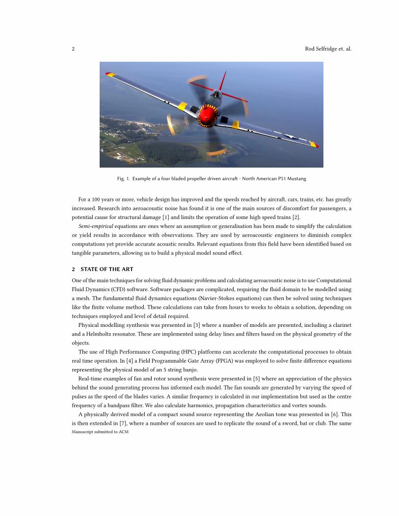
Fig. 2. Different sources of aeroacoustic noise associated with propellers, rotors and lift fans. Adapted from [12].
compact sound source was used in a portion of our propeller model, described in Section 4.3. A real-time physical modelof an aeroacoustic musical instrument was presented in [8] using similar techniques along with mechanical propertiesof a string.
A different approach was taken in [9] where sounds are synthesised to represent the interior of aircraft for designersto evaluate noise pollution. An analysis of recorded sounds are evaluated in the Fourier domain and then re-synthesisedin real time. Jet aeroplane noise is synthesised in [10]. This identifies that some of the tonal sounds are generated bywheel well cavities when the landing gear is extended. An analysis approach is used to identify tonal components inaircraft noise which are then synthesised by use of a sine wave with time-varying amplitude and frequency. Perceptualtests revealed that tonal noise above 4000 Hz was annoying. Therefore prediction of this, along with simultaneousbroadband aircraft noise, are useful for designers.
An extension of the Kirchhoff integral to produce a multipole expansion (monopole, dipole and quadrupole) of theaeroacoustic sound of a propeller was given in [11]. The purpose of an analytical derivation of the sound produced inthe far field is to allow propeller designers to apply reverse engineering. By setting the far field noise to acceptablelevels at specific observer positions, selective propeller parameters can be ascertained.
Our requirements for a propeller sound effect is to produce a model that captures many of the characteristics ofthe aeroacoustic sounds based on the physics of the interactions while operating in real-time. The model should haverelevant parameters allowing real-time interaction by a sound designer or game engine. Much of this research exploitstechniques and semi-empirical equations developed by aircraft engineers before the computational power required tosolve the fundamental equations was available.
3 METHOD
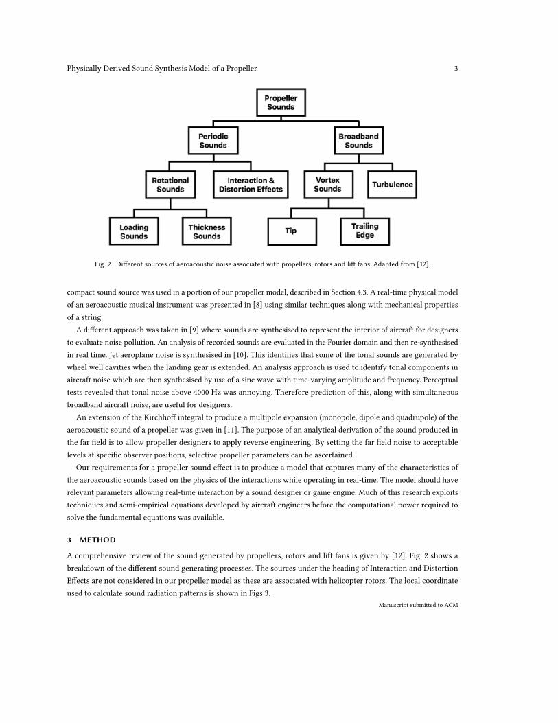
A comprehensive review of the sound generated by propellers, rotors and lift fans is given by [12]. Fig. 2 shows abreakdown of the different sound generating processes. The sources under the heading of Interaction and DistortionEffects are not considered in our propeller model as these are associated with helicopter rotors. The local coordinateused to calculate sound radiation patterns is shown in Figs 3.
Manuscript submitted to ACM
4 Rod Selfridge et. al.
Fig. 3. Local coordinates of spinning propeller
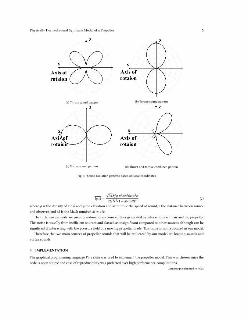
A main sources of aeroacoustic sound is from loading sounds. Sounds are generated by air pressure surrounding apropeller blade as air passes over it. There is a thrust component which is a pressure force normal to the plane of rotationof the propeller and a torque component which is a pressure component within the propeller plane. Under uniformconditions the two forces will be steady with respect to the blade. When viewed from a stationary reference point inthe disc of a rotating propeller, the pressure will pulsate as the blade passes this point. This generates a harmonic soundsource at the blade passing frequency. The separate and combined sound radiation patterns for thrust and torque areshown in Figs. 4a, 4b and 4d.
Thickness noise is the sound generated as the blade moves the air aside when passing. This sound is found to besmall when blades are moving at the speed of sound, 343 m/s, (known as a speed of Mach 1), and is not considered inour model [12].
The dominant broadband sources are vortex sounds which are created as each blade cuts through the air. A significantbody of research has been carried out in relation to vortices being shed as objects move through the air and the soundsgenerated are known as Aeolian tones. The vortices are generated at a given frequency as the propeller blade cutsthough the air and depends on the speed of air over the object. The radiation pattern for the vortex sounds is shown inFig 4c. An equation giving the frequency of vortex shedding fst is given in Eqn. 1.
fst =Stu
d(1)
where u is the airspeed, d the diameter and a value known as the Strouhal number St . Since the speed u is highest at thetip and slower towards the centre a wide band of sound is generated. The mean acoustic intensity, Il (t ), of the soundgenerated is proportional to u6 as given in Eqn. 2, (simplified from [13]).
Manuscript submitted to ACM
Physically Derived Sound Synthesis Model of a Propeller 5
(a) Thrust sound pattern (b) Torque sound pattern
(c) Vortex sound pattern (d) Thrust and torque combined pattern
Fig. 4. Sound radiation patterns based on local coordinates
Il (t ) ∼
√2πS2t ρ u
6sin2θcos2φ
32c3r2 (1 −Mcosθ )4(2)
where ρ is the density of air, θ and φ the elevation and azimuth, c the speed of sound, r the distance between sourceand observer, andM is the Mach number,M = u/c .
The turbulence sounds are pseudorandom noises from vortices generated by interactions with air and the propeller.This noise is usually from inefficient sources and classed as insignificant compared to other sources although can besignificant if interacting with the pressure field of a moving propeller blade. This noise is not replicated in our model.
Therefore the two main sources of propeller sounds that will be replicated by our model are loading sounds andvortex sounds.
4 IMPLEMENTATION
The graphical programming language Pure Data was used to implement the propeller model. This was chosen since thecode is open source and ease of reproducibility was preferred over high performance computations.
Manuscript submitted to ACM
6 Rod Selfridge et. al.
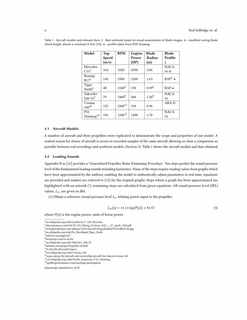
Table 1. Aircraft models and relevant data. ‡ - Best estimate based on visual examination of blade images. ⊕ - modified noting bladechord length almost a constiant 0.47m [14]. ⋆ - profile taken from RAF drawing
Model TopSpeed(m/s)
RPM EnginePower(HP)
BladeRadius(m)
BladeProfile‡
HerculesC131 164 1020 4590 2.06
NACA16 ⊕
BoeingB172 144 2500 1200 1.63 RAF3 ⋆TigerMoth4 48 21005 130 0.996 RAF ⋆
YakovlevYak-527 79 18608 360 1.209
NACA16
Cessna34010 125 250011 310 0.96
ARA-D
P51Mustang12 193 128013 1490 1.70
NACA16
4.1 Aircraft Models
A number of aircraft and their propellers were replicated to demonstrate the scope and properties of our model. Acentral reason for choice of aircraft is access to recorded samples of the same aircraft allowing as close a comparison aspossible between real recordings and synthesis models, (Section 5). Table 1 shows the aircraft models and data obtained.
4.2 Loading Sounds
Appendix B in [12] provides a ‘Generalized Propeller-Noise Estimating Procedure’. Ten steps predict the sound pressurelevel of the fundamental loading sounds including harmonics.Many of the steps require reading values from graphswhichhave been approximated by the authors, enabling the model to authentically adjust parameters in real time; equationsare provided and readers are referred to [12] for the original graphs. Steps where a graph has been approximated arehighlighted with an asterisk (*); remaining steps are calculated from given equations. All sound pressure level (SPL)values, Lx , are given in dBs.
(1) Obtain a reference sound pressure level Lα relating power input to the propeller:
Lα [n] = 15.11 log(P[n]) + 83.57 (3)
where P[n] is the engine power, units of horse power.
1en.wikipedia.org/wiki/Lockheed_C-130_Hercules2alternatewars.com/SAC/B-17G_Flying_Fortress_SAC_-_27_April_1949.pdf3i178.photobucket.com/albums/w252/YavorD/PropellorRAFT5291BE2C2D.jpg4en.wikipedia.org/wiki/De_Havilland_Tiger_Moth5rafjever.org/tigpic0276hercprops.com/in-stock/7en.wikipedia.org/wiki/Yakovlev_Yak-528airbum.com/pireps/PirepYak-52.html976.222.206.206/yak52/specs10en.wikipedia.org/wiki/Cessna_34011aopa.org/go-fly/aircraft-and-ownership/aircraft-fact-sheets/cessna-34012en.wikipedia.org/wiki/North_American_P-51_Mustang13spitfireperformance.com/mustang/mustangtest
Manuscript submitted to ACM
Physically Derived Sound Synthesis Model of a Propeller 7
(2) Correct for the number of blades and blade diameter:
Lβ = 20 log4B+ 40 log
4.72D
(4)
where B is the number of blades and D is the propeller diameter.(3) Obtain correction factor accounting for the speed of propeller rotation and distance between propeller and point
of interest, (stated as 1 foot ≈ 0.305m, [12]):
Lγ [n] = (25.12MT [n] − 33.40) log0.305D
+ (34.37MT [n] − 36.88)(5)
whereMT [n] is the Mach number of the blade tip.(4) Obtain the directional correction factor, taking into account the directional characteristics of a propeller. This
is similar to Gutin’s theory of propeller acoustics illustrated in [13], where the greatest acoustic intensity is given atapproximately 120° to the direction of flight:
Lδ [n] = −5.3x10⁻³θ2[n] + 1.19θ[n] − 62.32 (6)
where θ[n] is the azimuth angle between source and observer. A minimum value of −20dB is set to match measuredplots given in [15].
(5) Correct for spherical attenuation of sound relative to distance between observer and source:
Lϵ [n] = −20 log(3.375r [n] − 1) (7)
where r [n] is the distance between observer and source in metres.(6) Sum all the SPL values to obtain value at the reference point.
Lζ [n] = Lα [n] + Lβ + Lγ [n] + Lδ [n] + Lϵ [n] (8)
(7) Calculate the harmonic distribution of sound up to the 10th harmonic:
HN [n] = 26e−(−0.7MT [n]+0.79)N − 22 (9)
where HN [n] is the gain of each harmonic (dB) and N is the harmonic number.(8) The values obtained for HN [n], with N ∈ [1, 10] are subtracted from Lζ [n] to give individual SPL values for each
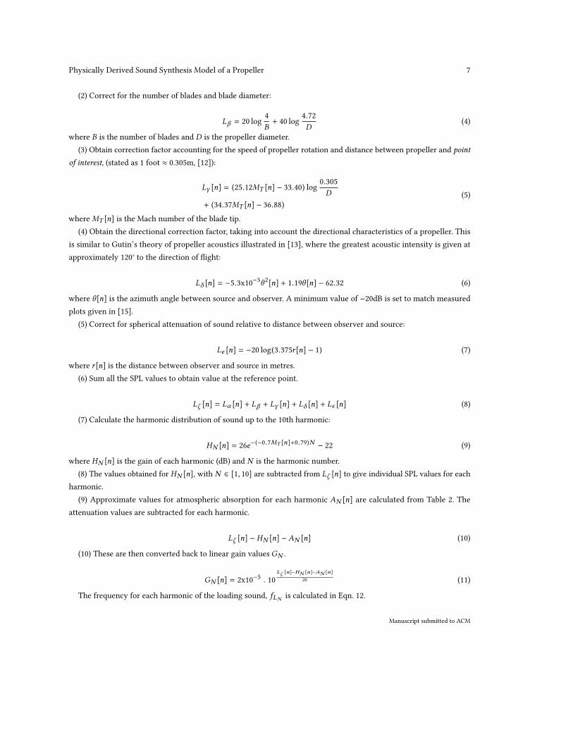
harmonic.(9) Approximate values for atmospheric absorption for each harmonic AN [n] are calculated from Table 2. The
attenuation values are subtracted for each harmonic.
Lζ [n] − HN [n] −AN [n] (10)
(10) These are then converted back to linear gain values GN .
GN [n] = 2x10⁻⁵ . 10Lζ [n]−HN [n]−AN [n]
20 (11)
The frequency for each harmonic of the loading sound, fLN is calculated in Eqn. 12.
Manuscript submitted to ACM
8 Rod Selfridge et. al.
Table 2. Approximate values for atmospheric absorption for each frequency band, † estimate by authors
FrequencyBands (Hz)
Attenuation fromnoise source, AN [n](dB per 1000 feet)
[0, 90) 0[90, 180) 0.2[180, 355) 0.6[355, 710) 1[710, 1400) 1.8[1400, 2800) 3.3[2800, 5600) 6[5600, 11,200) 11.4> 11,200 20†
fLN [n] =NB . RPM[n]
60(12)
where RPM[n] stands for revolutions per minute. Each harmonic is implemented as noise filtered by a variable bandpassfilter where the passband of the filter is centred on the harmonic frequency. The harmonic gain value was set to thevalue calculated in step 10.
4.3 Vortex Sounds
Compact sound source models from [6] are used to synthesise vortex sound. To replicate a propeller blade a numberof these sources are ‘placed’ in a row to represent different points on a propeller blade, similar to [7]. Each blade isrepresented by 7 compact sources.
The main difference found in relation to a propeller blade compared with the cylinder modelled presented in [6] isthat the fundamental frequency of Eqn. 1 was found to correspond to a Strouhal number St = 0.85 [16] as opposed toSt ≈ 0.2 for a cylinder. The diameter used in Eqn. 1 to calculate the frequency becomes the propeller chord length andeach harmonic frequency fstN is shown in Eqn. 13:
fstN [n] =0.85Nu[n]
Chord Length(13)
The different chord lengths and chord positions along the length of the blade were all obtained from a historicalRAF blade profile3. We calculate the speed of each source u[n] using the source radius and RPM[n] value. Two otherpropeller blade profiles were presented in [17]. These are labelled NACA 16 and ARA-D and similar data were obtainedfrom these two profiles and applied to the synthesis model.
The gain is calculated from a discrete implementation of Eqn. 2.
4.4 Motor Sounds
The propeller in an aeroplane is not heard in isolation; the motor is often a major sound source. How loudly we hearthe motor depends on its characteristics, distance and any masking by aeroacoustic sounds. Missing the roughnessassociated with a four stroke propeller motor may have perceptual implications. The fuel supply mixture may alsobe relevant. Depending on era these may be normally aspirated, fuel injected or turbo. It was not the purpose of ourManuscript submitted to ACM
Physically Derived Sound Synthesis Model of a Propeller 9
design to replicate the motor component so a model was adapted from the helicopter sound effect in [5]. A very smallrandom factor was added to the RPM value for each propeller unit to model small differences between the engines.
5 RESULTS
Exact comparisons between recorded samples and our physical models are limited. When examining the output signal ofthe recordings, details of the operating conditions and flight paths were not provided. Therefore aircraft speed, distanceand propeller RPM were unknown. Recordings only provided details of the type of aircraft; propeller dimensions andother properties have been obtained to try and give as fair an evaluation as possible.
5.1 Objective Evaluation
A comparison between a recorded sample and a sample from our physical model was performed. The recorded samplewas of a Cessna, taken from the BBC Sound Effect Library, (AircraftCessna.BBC.EC1A4b.wav). The Cessna is a smalllight propeller powered aircraft but further model details such as the model number are unknown.
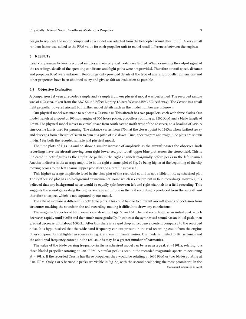
Our physical model was made to replicate a Cessna 340. This aircraft has two propellers, each with three blades. Ourmodel travels at a speed of 100 m/s, engine of 300 horse power, propellers spinning at 2200 RPM and a blade length of0.96m. The physical model moves in virtual space from south east to north west of the observer, on a heading of 319°. Asine-cosine law is used for panning. The distance varies from 370m at the closest point to 1163m when furthest awayand descends from a height of 325m to 50m at a pitch of 7.9° down. Time, spectrogram and magnitude plots are shownin Fig. 5 for both the recorded sample and physical model.
The time plots of Figs. 5a and 5b show a similar increase of amplitude as the aircraft passes the observer. Bothrecordings have the aircraft moving from right lower red plot to left upper blue plot across the stereo field. This isindicated in both figures as the amplitude peaks in the right channels marginally before peaks in the left channel.Another indicator is the average amplitude in the right channel plot of Fig. 5a being higher at the beginning of the clip,moving across to the left channel upper plot after the aircraft has passed.
This higher average amplitude level in the time plot of the recorded sound is not visible in the synthesised plot.The synthesised plot has no background environmental noise which is ever present in field recordings. However, it isbelieved that any background noise would be equally split between left and right channels in a field recording. Thissuggests the sound generating the higher average amplitude in the real recording is produced from the aircraft andtherefore an aspect which is not captured by our model.
The rate of increase is different in both time plots. This could be due to different aircraft speeds or occlusion fromstructures masking the sounds in the real recording, making it difficult to draw any conclusions.
The magnitude spectra of both sounds are shown in Figs. 5c and 5d. The real recording has an initial peak whichdecreases rapidly until 500Hz and then much more gradually. In contrast the synthesised sound has an initial peak, thengradual decrease until about 1000Hz. After this there is a rapid drop in frequency content compared to the recordednoise. It is hypothesised that the wide band frequency content present in the real recording could from the engine,other components highlighted as sources in Fig. 2, and environmental noises. Our model is limited to 10 harmonics andthe additional frequency content in the real sounds may be a greater number of harmonics.
The value of the blade passing frequency in the synthesised model can be seen as a peak at ≈110Hz, relating to athree bladed propeller rotating at 2200 RPM. A similar peak is seen in the recorded magnitude spectrum occurringat ≈ 80Hz. If the recorded Cessna has three propellers they would be rotating at 1600 RPM or two blades rotating at2400 RPM. Only 4 or 5 harmonic peaks are visible in Fig. 5c, with the second peak being the most prominent. In the
Manuscript submitted to ACM
10 Rod Selfridge et. al.
(a) Time plot of recorded propeller plane. (b) Time plot of synthesised propeller plane.
(c) Magnitude plot of recorded propeller plane. (d) Magnitude plot of synthesised propeller plane.
(e) Spectrogram of recorded propeller plane. (f) Spectrogram of synthesised propeller plane.
Fig. 5. Time plots and spectrograms of recorded and synthesised propeller powered aeroplane sounds.
synthesised sound the first peak is the highest and the remaining 9 decrease as calculated by the ten steps described insection 4.
The decrease in harmonic frequencies highlights the Doppler effect created as the aircraft passes the observer, visiblein Figs. 5e and 5f. The frequency content of the recorded sound has the majority of the wide band noise when theaircraft is at its closest, ≈ 6 seconds. As this is not present throughout the clip it is a good indication that this is soundfrom the aircraft not captured by our model.
Manuscript submitted to ACM
Physically Derived Sound Synthesis Model of a Propeller 11
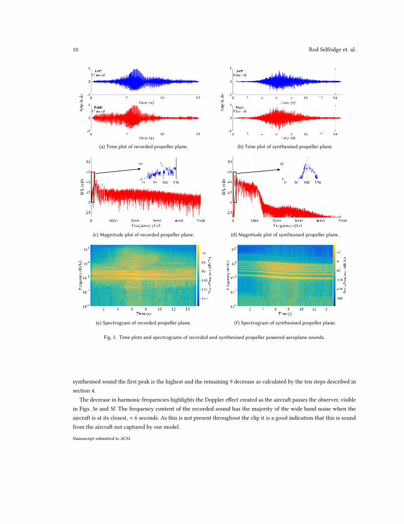
Fig. 6. Mean plausibility rating for different sample types, including 95% confidence intervals. PM = Physical Model.
5.2 Subjective Evaluation
A double blind listening test was carried out to evaluate the effectiveness of our synthesis model. 20 participants, 6female and 14 male, aged between 17 and 70, with a median age of 39, were asked to rate a number of sounds forauthenticity. Each participant was presented with 4 test pages, in which each page contained 2 real samples, 2 samplesfrom our model, 2 samples generated by sinusoidal modelling synthesis (SMS) [18] of a recording, and an anchor, whichwas created by downgrading the quality of our model. The anchors were created from the downgraded synthesis signal,to allow a thorough comparison of how plausible the synthesis method is compared to the recorded sample. It wasexpected that a low pass filtered sample, as used in the MUSHRA standard, would still be considered plausible, whereasa low quality downgraded anchor would encourage the full use of the scale and allow for better understanding as toeffectiveness of the synthesis method.
The Web Audio Evaluation Tool [19] was used to build and run listening tests in the browser. It provides all thesample loudness normalisation, presentation order randomisation and results reporting in an intuitive way. This allowedtest page order and samples on each page to be randomised. All samples were loudness normalised in accordancewith [20].
The mean perceptual rating for all 24 clips is shown in Fig. 6. It can be seen that the real recordings received thehighest mean plausibility rating and the anchor the lowest. There was little difference between the two synthesismethods. We performed one-way ANOVAs to determine the impact of synthesis method on the user authenticityratings. Both synthesised methods were significantly worse than a recorded sample (p < 0.0001) but there was nosignificant difference between the synthesis methods (p < 0.05).
This was not unexpected and it is envisaged our model could be improved with further development and a betterengine sound effect. The advantage of our synthesis method is the real-time operation with parameters based on actualaircraft behaviour and propeller characteristics. SMS techniques offer no method for deterministic parameter control.Common comments relating to our model were “decay too slow”, “echo-like”, “plausible”, “warlike”, “too smooth” and “Iwould expect more stutter”.
Manuscript submitted to ACM
12 Rod Selfridge et. al.
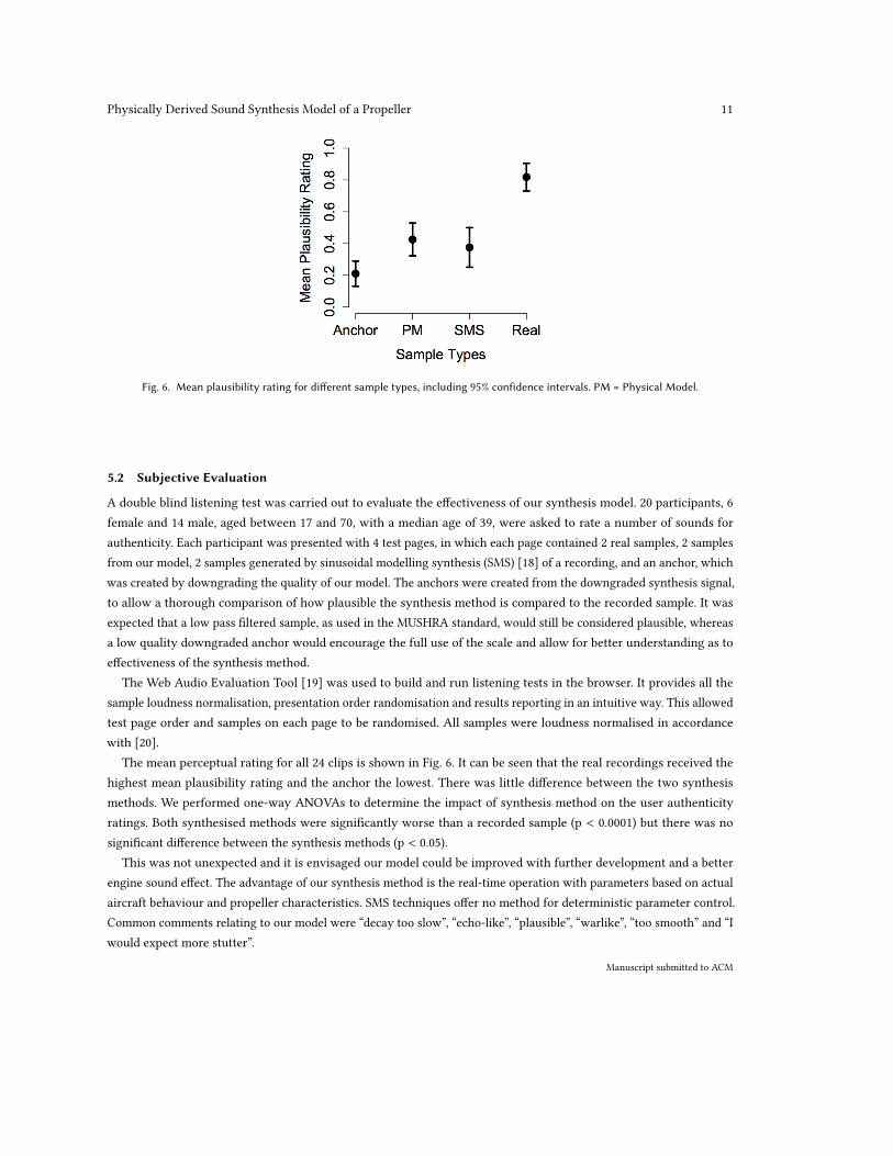
Fig. 7. Pure Data GUI.
6 DISCUSSION
A main challenge of designing the model was evaluating the relative levels of loading sound, vortex sounds and soundfrom the motor. No values were forthcoming from the literature, which is understandable considering the relationshipwill vary with motor type, blade design, and other design factors. Three gain sliders were provided in the model GUI toenable users to set these themselves, Fig. 7. The software is open source and users are able to modify the software tosuit their requirements14.
The motor powering the propellers may have a large influence on the perceived sound, especially when the observeris close to the plane. The engine model taken from [5] was designed to model a modern helicopter motor and hence maynot capture inherent sounds associated with propellered aircraft. A more specific engine model would increase realism.
It is not ideal to compare our model with a recorded sound with limited details available. A more comprehensiveobjective and subjective evaluation of our propeller model would be comparing the sound produced by our model witha known aircraft, flying a known flight path past the observer. This would enable us to replicate the conditions exactlyand perform a direct comparison. It is also noted that an actual recording will include ground reflections and mayinclude compression, reverb and other audio effects, enhancing the sound quality and adding to perceived realism; ourmodel has no such processing.
By implementing more of the sound sources identified in Fig. 2 or increasing the number of harmonics synthesised,further improvementsmay be achieved, enhancing realism. Sounds fromwheels, wheel wells, flaps and other componentswere not replicated and addition of these factors may increase authenticity. Our implementation requires approximatinga number of plots in [12] to calculate the loading sounds. This may cause some details to be absent in our physicalmodel.14A model demo and listening test sound files are available at https://code.soundsoftware.ac.uk/hg/propeller-model
Manuscript submitted to ACM
Physically Derived Sound Synthesis Model of a Propeller 13
The flight path and behaviour was programmed by the authors, an example is given in section 5.1. A futuredevelopment could have parameters automated by attaching it to an aircraft object in a game engine, where the flightpath is determined within gameplay15.
7 CONCLUSION
Presented in this paper is a real-time physical sound effect synthesis model. It is based on semi-empirical equationsidentified from research in fluid dynamics and aerodynamics giving an approximation of the noise generated by apropeller. These equations and procedures were developed in order for design engineers to minimise the noise from theidentified sources.
We have used these equations to produce a sound synthesis model that gives an acceptable approximation to actualsounds without the computational expense of solving the Navier - Stokes equations, common in computationally heavyCFD techniques.
Our interface provides a number of aircraft models. Although specific aircraft have been chosen as an example inour implementation, any propeller can be modelled given the correct dimensions and properties.
REFERENCES[1] HH Heller, DG Holmes, and EE Covert. Flow-induced pressure oscillations in shallow cavities. Journal of Sound and Vibration, 18, 1971.[2] H Fujita. The characteristics of the Aeolian tone radiated from two-dimensional cylinders. Fluid dynamics research, 42, 2010.[3] PR Cook. Real sound synthesis for interactive applications. CRC Press, 2002.[4] F Pfeifle and R Bader. Real-time finite-difference method physical modeling of musical instruments using field-programmable gate array hardware.
Journal of the Audio Engineering Society, 63, 2016.[5] A Farnell. Designing sound. MIT Press Cambridge, 2010.[6] R Selfridge et al. Physically derived synthesis model of Aeolian tones. Best Student Paper Award - 141st Audio Engineering Society Convention, LA,
USA, 29 Sept - 2 Oct 2016.[7] R Selfridge, D Moffat, and JD Reiss. Real-time physical model for synthesis of sword sounds. Sound and Music Computing, Espoo, Finland, 5 - 8 July,
2017.[8] R Selfridge et al. Real-time physical model of an Aeolian harp. 24th International Congress on Sound and Vibration, London, 23-27 July 2017.[9] K Janssens et al. Real-time synthesis and sound quality evaluation of interior aircraft noise. In Proc. Forum Acusticum, Budapest, Hungary, 29 Aug - 2
Sept 2005.[10] D Berckmans et al. Model-based synthesis of aircraft noise to quantify human perception of sound quality and annoyance. Journal of Sound and
Vibration, 311, 2008.[11] LMBC Campos and FJP Lau. On a generalized multipole expansion with application to propeller design synthesis. International Journal of
Aeroacoustics, 13, 2014.[12] JE Marte and DW Kurtz. A review of aerodynamic noise from propellers, rotors, and lift fans. Jet Propulsion Laboratory, California Institute of
Technology, 1970.[13] ME Goldstein. Aeroacoustics. McGraw-Hill International Book Co., 305 p., 1976.[14] R E Donham and D J Osterholt. Utilizing test results to show adding flexibility of propeller blades is more representative than the classical rigid
blade propeller whirl flutter analysis. In Proceedings of International Forum on Aeroelasticity and Structural Dynamics (IFASD), Stockholm, Sweden,18-20 June 2007.
[15] EZ Stowell and AF Deming. Noise from two-blade propellers. NACA Technical Report 526., 1936.[16] D Brown and J B Ollerhead. Propeller noise at low tip speeds. Technical report, DTIC Document, 1971.[17] PJW Block. Analysis of noise measured from a propeller in a wake. NASA Technical Report, 1984.[18] X Amatriain et al. Spectral processing. DAFX: Digital Audio Effects, 2002.[19] N Jillings et al. Web audio evaluation tool: A browser-based listening test environment. Sound and Music Computing, Maynooth, Ireland, 30 July - 1
August 2015.[20] Recommendation ITU-R BS.1534-3. Method for the subjective assessment of intermediate quality level of audio systems. International Telecommuni-
cation Union Radiocommunication Assembly, 2015.
15An example of the sound effect added to a film clip is available at https://www.youtube.com/watch?v=xOclT8EiiU4
Manuscript submitted to ACM