PHYSICAL MODELING OF SMALL-BOAT HARBORS: … · technical report cerc-92-12 physical modeling of...
172
TECHNICAL REPORT CERC-92-12 PHYSICAL MODELING OF SMALL-BOAT HARBORS: ofEniner DESIGN EXPERIENCE, LESSONS LEARNED, AD-A258 700 AND MODELING GUIDELINES lIII1ll lii 111 11 I.1 .. .l1ll11 ll l Ii by Robert R. Bottin, Jr. A " Coastal Engineering Research Center DEPARTMENT OF THE ARMY Waterways Experiment Station, Corps of Engineers 3909 Halls Ferry Road, Vicksburg, Mississippi 39180-6199 DTIO DE0 6 1V99Z September 1992 (_0 Final Report 922 Approved For Public Release; Distribution Is Unlimited 92 12 15 034 Prepared for DEPARTMENT OF THE ARMY US Army Corps of Engineers Washington, DC 20314-1000 A' Under Work Unit "Shallow Draft Coastal Port Design"
-
Upload
nguyenthien -
Category
Documents
-
view
219 -
download
1
Transcript of PHYSICAL MODELING OF SMALL-BOAT HARBORS: … · technical report cerc-92-12 physical modeling of...
TECHNICAL REPORT CERC-92-12
PHYSICAL MODELING OF SMALL-BOAT HARBORS:ofEniner DESIGN EXPERIENCE, LESSONS LEARNED,
AD-A258 700 AND MODELING GUIDELINESlIII1ll lii 111 11 I.1 .. .l1ll11 ll l Ii by
Robert R. Bottin, Jr.
A " Coastal Engineering Research Center
DEPARTMENT OF THE ARMYWaterways Experiment Station, Corps of Engineers
3909 Halls Ferry Road, Vicksburg, Mississippi 39180-6199
DTIODE0 6 1V99Z
September 1992
(_0 Final Report
922 Approved For Public Release; Distribution Is Unlimited
92 12 15 034
Prepared for DEPARTMENT OF THE ARMYUS Army Corps of Engineers
Washington, DC 20314-1000
A' Under Work Unit "Shallow Draft Coastal Port Design"

Destroy this report when no longer needed. Do not returnit to the originator.
The findings in this report are not to be construed as an officialDepartment of the Army position unless so designated
by other authorized documents.
The contents of this report are not to be used for
advertising, publication, or promotional purposes.Citation of trade names does not constitute anofficial endorsement or approval of the use of
such commercial products.

Form ApprovedREPORT DOCUMENTATION PAGE OMB No. 0704-0188
PUbliC repoting burden for this collection of information is estimated to average r hour per response, including the time for reviewing instructiOns. searching existing data sources.
gathering and maintaining the data needed, and completing and reviewing the collection of information. Send comments regarding this burden estimate or any other aspect of thiscollectiOn of information, including suggestions for reducing this burden to Washington Headquarters Services, Directorate for information Operations and Reports, 1215 Jefferson
Davis Highway. Suite 1204, Arlington, VA 22202-4302. and to the Office of Management and Budget, Paperwork Reduction Project (0704-0188). Washington. DC 20503.
1. AGENCY USE ONLY (Leave blank) 2. REPORT DATE 3. REPORT TYPE AND DATES COVEREDI September 1992 Final report
4. TITLE AND SUBTITLE S. FUNDING NUMBERS
Physical Modeling of Small-Boat Harbors:Design Experience, Lessons Learned, andModeling Guidelines
6. AUTHOR(S)
Robert R. Bottin, Jr.
7. PERFORMING ORGANIZATION NAME(S) AND ADORESS(ES) 8. PERFORMING ORGANIZATION
US Army Engineer Waterways Experiment Station REPORT NUMBER
Coastal Engineering Research Center3909 Halls Ferry Road Technical ReportVicksburg, MS 39180-6199 CERC-92-12
9. SPONSORING/ MONITORING AGENCY NAME(S) AND ADDRESS(ES) 10. SPONSORING/ MONITORINGAGENCY REPORT NUMBER
US Army Corps of EngineersWashington, DC 20314-1000
11. SUPPLEMENTARY NOTES
Available from National Technical Information Service, 5285 Port Royal Road,Springfield, VA 22161
12a. DISTRIBUTION /AVAILABILITY STATEMENT 12b. DISTRIBUTION CODE
Approved for public release; distribution is unlimited
13. ABSTRACT (Maximum 200 words)
This report summarizes the knowledge and insight gained on small-boatharbor design through years of physical model investigations conducted at theUS Army Engineer Waterways Experiment Station. An inventory of physicallymodeled, small-boat harbor projects has been complied and reviewed. Small-boat harbors modeled and subsequently constructed in the prototype, also havebeen identified. Site specific performance of these projects has beenreviewed to determine if the designs recommended in the model investigationswere built as recommended and if they have functioned successfully in theprototype. These reviews and study efforts have resulted in a summary oflessons learned through physical modeling of small-boat harbors and site spe-cific performance in the prototype. Types of small-boat harbors and typicalproblems, physical modeling in general, and physical modeling guidelines alsoare included in this report.
14. SUBJECT TERMS 15. NUMBER OF PAGES
See reverse. 170
16. PRICE CODE
17. SECURITY CLASSIFICATION 18. SECURITY CLASSIFICATION 19. SECURITY CLASSIFICATION 20. LIMITATION OF ABSTRACT
OF REPORT OF THIS PAGE OF A3STRACT
UNCLASSIFIED UNCLASSIFIED I II
NSN 7540-01-280-5500 Standard Form 298 (Rev 2-89)Prescribed by ANSi Sitd 19-18298-102

14. (Concluded).
Harbor classification Inlet stability Prototype harbor performanceHarbor design Modeling guidelines Small-boat harborsHarbor shoaling Physical modeling Wave action

PREFACE
A research work unit entitled "Shallow Draft Coastal Port Design" was
initiated to determine the state of knowledge of small-boat harbor design.
Existing design criteria for small craft harbor design is based on "rule-of-
thumb" or "down-sized" deep-draft navigation channel design criteria. This
research will consolidate existing knowledge on small-boat harbor design and
identify research activities needed to fill gaps in existing design criteria.
Upon completion, this research will provide comprehensive US Army Corps of
Engineers guidance for small-boat harbor design which will be published in an
engineer manual.
Overall management of the project is by Headquarters, US Army Corps of
Engineers (HQUSACE). Mr. Glenn Drummond, HQUSACE, served as Technical Moni-
tor. This work was carried out at the Coastal Engineering Research Center
(CERC), US Army Engineer Waterways Experiment Station (WES), under the general
supervision of Dr. James R. Houston and Mr. Charles C. Calhoun, Jr., Director
and Assistant Director of CERC, respectively; Mr. Thomas W. Richardson, Chief,
Engineering Development Division, CERC; Ms. Joan Pope, Chief, Coastal Struc-
tures and Evaluation Branch, CERC; and Mr. Jeff Lillycrop, Principal Investi-
gator, CERC. The work was conducted by and the report prepared by
Mr. Robert R. Bottin, Jr., Physical Scientist, CERC, under the direct guidance
of Mr. C. E. Chatham, Jr., Chief, Wave Dynamics Division, CERC; and Mr. Dennis
G. Markle, Chief, Wave Processes Branch, CERC. This report was typed by
Ms. Debbie S. Fulcher, CERC.
At the time of publication of this report, Director of WES was
Dr. Robert W. Whalin. Commander and Deputy Director was
COL Leonard G. Hassell, EN. Accesion For
NTIS CRA&I
DTIC TABUnannounced iJustification
S.................................
ByDistribution
Availability Codes
Avail a:bd Ior.Dist Special
.. . .

CONTENTS
Page
PREFACE ............................... ................................ 1
CONVERSION FACTORS, NON-SI TO SI (METRIC)UNITS OF MEASUREMENT ....................... ........................ 3
PART I: INTRODUCTION ...................... ........................ 4
General ............................................ 4Types of Small-Boat Harbors and Typical Problems ....... ........ 5Physical Modeling as a Design Tool .............. ............... 8
PART II: PHYSICALLY MODELED HARBORS .......... ................. .. 14
Inventory .................... ............................ .. 14Brief Case Histories ............... ...................... 16Discussions .................... ........................... .. 105
PART III: PHYSICALLY MODELED HARBORS WHICH HAVE BEEN CONSTRUCTED 108
Inventory .................... ............................ 108Site Specific Construction and Performance ..... ........... .. 109Discussions .................... ........................... .. 147
PART IV: SUMMARY OF LESSONS LEARNED ........ ................. .. 149
PART V: FUTURE RESEARCH ACTIVITIES RECOMMENDED . . . ........ 154
PART VI: PHYSICAL MODELING GUIDELINES ........ ................ .. 157
Small-Scale Harbor Models ............ .................... .. 157Design Information Required for Model Investigations ...... .. 158
REFERENCES ....................... .............................. 163
2

CONVERSION FACTORS, NON-SI TO SI (METRIC)UNITS OF MEASUREMENT
Non-SI units of measurement used in this report can be converted to SI(metric) units as follows:
Multiply By To Obtain
acres 4046.856 square metres
cubic feet 0.02831685 cubic metres
degrees (angle) 0.01745329 radians
feet 0.3048 metres
inches 25.4 millimetres
miles (US statute) 1.609344 kilometres
pounds (force) 4.4482224 newtons
tons (2,000 lb, force) 8896.444 kilonewtons
3
PHYSICAL MODELING OF SMALL-BOAT HARBORS:
DESIGN EXPERIENCE. LESSONS LEARNED,
AND MODELING GUIDELINES
PART I: INTRODUCTION
General
1. A research work unit entitled "Shallow Draft Coastal Port Design"
has been initiated to determine the state of knowledge on small-boat harbor
design. Existing state-of-the-art design criteria for small-craft harbors is
based primaiily on "rule-of-thumb" or "down-sized" deep-draft navigation chan-
nel design criteria. The study will consolidate existing knowledge on small-
boat harbor design and identify research activities needed to fill gaps in
existing design criteria. Upon completion, this research will provide com-
prehensive US Army Corps of Engineers guidance for small-craft harbor design.
2. As part of the work unit, this report summarizes the state of knowl-
edge on design experience gained through physical modeling of small-boat har-
bors. An inventory of small-boat harbor projects that have been modeled has
been compiled and reviewed. This review identifies modifications made to the
original project designs as a result of the model investigations. Harbor
modifications are generally made to provide adequate or improve existing wave
protection, alleviate undesirable current conditions or flood flows, reduce
shoaling, or decrease amplification of long period wave energy in the harbor.
Small-boat harbors, that have been modeled and subsequently constructed in the
prototype, also have been identified in this report. Site specific perfor-
mance of these projects has been reviewed to determine if the designs recom-
mended in the model investigations were successful in the prototype.
3. These reviews and study efforts have resulted in a summary of les-
sons learned through physical modeling with respect to small-boat harbor de-
sign. As a result of lessons learned through physical modeling of small-boat
harbors and site specific performance of various projects in the prototype,
physical model usage guidelines have been established. The design engineer
may refer to these guidelines to determine where and how physical model inves-
tigations are used to solve particular coastal engineering problems. This
section will guide planning and design engineers through all stages of
4
physical modeling. Future research activities, which are required to develop
a complete design criteria for small-craft harbor projects, also have been
identified.
Types of Small-Boat Harbors and Typical Problems
4. A harbor is an area of water that is protected from wave action to
the extent that vessels are provided safe anchorage and mooring, loading, and
unloading conditions. Most small-craft harbors are marinas with facilities to
moor and service recreational boats or harbors of refuge designed for boats in
distress and transient boaters. Small-boat harbors usually have entrance
channel depths of 20 ft* or less. A review of over 350 harbor sites with
structural components that are under the jurisdiction of the Corps of
Engineers has been completed, and a small-boat harbor categorization scheme
has been formulated to assist in the development of a comprehensive classifi-
cation scheme for shallow-draft coastal ports. The review revealed that most
harbors are situated within one of three geographical settings which are as
follows:
a. Harbors situated along open coasts. This setting applies toharbors located along the Atlantic, Pacific, and Gulf Coasts,and the coasts of the Great Lakes. With their open exposure tolarge water bodies with long fetches and distant storms, theseharbors are subject to significant wave energy.
b. Harbors situated in the lee of natural land masses. Numerousharbors have been developed in the lee or shadow of natural landmasses, or barrier islands, which provide sheltering from waveenergy from some directions of approach. These harbors may beexposed to wave energy from the open ocean from limited direc-tions of approach. They are occasionally situated in largebodies of water where large locally generated waves may causesignificant damage during periods of storms.
C. Harbors situated in small bodies of water. This setting appliesto harbors located in lagoons, small lakes, bays, channels,canals, and rivers. They are generally not subjected to largewaves, but may experience damage due to locally generated wavesassociated with storm conditions.
5. Regardless of the geographical settings in which small-craft harbors
have been developed, most harbors can be categorized by physical character-
istics relative to their geometry and position along the various shorelines.
SA table of factors for converting non-SI units of measurements to SI(metric) units is presented on page 3.
5

Classification of harbors and typical engineering problems based on the
physical characteristics are discussed in the following subparagraphs.
a. Harbors constructed seaward of the shoreline and protected bybreakwaters. Most small-craft harbors fit into this category.Some are built along a straight shoreline and protected entirelyby breakwaters, while others are constructed in coves or irregu-larities in the shoreline, thus utilizing natural protection forwaves from various directions and minimizing breakwater lengths.Harbors constructed seaward of the shoreline generally requireminimal dredging since their entrances and basins are inrelatively deep water. These greater depths, however, requiremore material for the construction of protective breakwaters.Generally, when breakwaters enclosing a harbor extend to andterminate in relatively deep water, shoaling in the entrance isminimized and maintenance dredging requirements are reduced oreliminated. However, in instances where large volumes of sedi-ment are moving alongshore, material moves around the structuresand deposits in the entrance channel, thus, requiring routinemaintenance dredging. In some cases, structures extending intodeep water may also intercept the movement of sediment. Thismay prevent natural bypassing and result in accretion on theupdrift side and erosion on the down coast side of the harborentrance. Harbors built seaward of the shoreline often aresubjected to large waves in the entrance, which may result innavigation difficulties. Waves propagating directly through theentrance or diffracting through the entrance into the mooringareas may result in undesirable berthing conditions. Waveenergy transmitted through breakwaters and wave overtopping ofstructures may result in adverse conditions in anchorage ormooring areas.
b. Harbors constructed seaward of the shoreline and protected bybreakwaters with inner basins built inland through the shore-line. Many harbors have been developed with structures seawardof the shoreline and protected by breakwaters with the additionof inner basins through the shoreline. The inner basins aredredged through the shoreline or are natural irregularities inthe shoreline. The inner basins are normally used for small-boat mooring, since they are relatively calm. Harbors of thistype may experience the same engineering problems as discussedin paragraph 5a. Also, in some instances, waves propagate intothe inner basins and cause undesirable conditions which candamage vessels and facilities. Harbor oscillation problemsmight occur in inner basins if the frequencies of the modes ofoscillation of the basins are similar to the period of incomingwave energy. These conditions may result in amplification ofwave heights in antinodal areas (normally in the corners of thebasins) and strong horizontal currents in nodal regions, whichcould cause damage to small-craft and harbor facilities.
c. Harbors constructed inland with an entrance through the shore-line. Harbors of this type are located along numerous coast-lines. These harbors normally require more dredging than otherharbor types; however, in many instances a channel may bedredged through the shoreline to an existing lake, embayment,
6

lagoon, etc. and result in minimal dredging. Since the harboris located inland, it is normally more sheltered from storm waveactivity and thus requires smaller breakwaters, constructed inshallower water. Since the breakwaters terminate in relativelyshallow water (in the breaker zone), problems with breakingwaves in the entrance are sometimes experienced as well asstrong cross currents which can create hazardous navigationconditions for small craft. Shoaling of the entrance in shallowwater is more likely than in deep water due to material beingtransported in the breaker zone. Other problems that may beexperienced with harbors of this type are direct wave penetra-tion into the inner basins and long-period harbor oscillationswhich may result in facility and/or small-boat damages. On theGreat Lakes, seiching may occur and create hazardous currentconditions in the harbor entrance.
d. Harbors of the classes in paragraphs'5a. 5b, and 5c with riversentering into them. Numerous harbors constructed along thecoasts as classified by 5a, b, and c have rivers emptying intothem. This may present additional engineering problems. Riverflood flows may cause significant damages to harbor facilitiesand small-craft vessels. Also, sediment carried downstream by
river currents can result in substantial deposits in the harborand could require maintenance dredging. In some cases, riversempty adjacent to harbor entrances or in the nearby vicinity.Flood flows may swell over the river banks and cause damages inadjacent harbors. These rivers may also deposit sediments alongthe coast in the vicinity of the harbor entrance. This mate-rial, moved by tides and wave action, could result in entranceshoaling subsequently requiring increased dredging.
e. Harbors constructed inside river mouths. Many small-boat har-bors have been built inside river mouths along the variouscoastlines. These harbors normally require minimal initialdredging. Small boats usually are sheltered from most largewaves, and similar to harbors built inland, relatively shortbreakwater lengths constructed in shallow water are required toprovide entrance wave protection. Problems with wave breakingin the entrance, cross-currents, and wave-induced shoaling mayoccur similar to that of inland harbors. Flood flows also mayresult in damages in the harbor, and sediment moving downstreamcould result in shoaling deposits in the lower reaches of theriver, thus requirirg dredging. In some areas, the passage ofice downstream may cause harbor damages or may result in flood-ing due to ice jams. River flows opposing incoming waves in theentrance can result in peaked wave crests and treacherous cur-rents and c¢use navigation difficulties in river mouths. Insome cases waves propagate directly up the axis of the river andcause damages to small boats and harbor facilities during stormactivity. Other areas have experienced problems with harboroscillations or surging of basins built adjacent to the riverbank which results in damages in the harbor.
f. Harbors constructed in inlets. Numerous harbors of the variousclassifications have been constructed in inlets along the oceancoasts. These harbors are normally protected from heavy wave
7

action, however, significant problems may result in the inletentrance. In unstabilized inlet openings, shoaling normallyoccurs and the entrance meanders due to longshore sedimenttransport, wave action, and tidal activity. This causes hazard-ous navigation conditions. To stabilize the inlet opering,dredging and/or the construction of jetties are required toprovide protection to the entrance. In some cases, jetties mustbe long enough to extend beyond the ebb tidal delta. Againshoaling problems and adverse wave and current conditions may beencountered in the jettied entrance which could create hazardsto navigation. Tidal exchange between the ocean and embaymentmay create high-velocity flood and ebb currents through theentrance, and sediment moving alongshore due to wave action maybe influenced by these tidal currents and create an unstablemeandering entrance condition. Low-crested weirs are installedin some cases to allow sediment to migrate over the jetty. Inthe lee of the weir a deposition basin is dredged where thesediment falls out and does not come under the influence oftidal currents. Periodic dredging of deposition basins is re-quired to keep them effective or sand bypassing plants may beutilized.
6. In summary, problems normally occur in small-boat harbors in the
entrance, in the outer harbor, and/or the inner harbor. Problems in the en-
trance include shoaling, excessive wave activity, and adverse current condi-
tions. In the outer harbor, anchorage and mooring areas normally encounter
problems with excessive wave action that penetrjtes through the entrance or
wave energy that is transmitted through and/or overtops the breakwaters.
Inner harbor problems normally result due to wave energy penetrating through
the entrance and outer harbor into the basins or due to oscillations in the
basins that are forced by longer-period wave energy. Where rivers enter vari-
ous harbor sites or where harbors are built in river mouths, additional prob-
lems are experienced due to river currents, flood flows, sediment movement,
and in some cases, ice moving downstream. Harbors built within embayments in
tidal inlets may experience the same problems as stated above, however, an
additioril problem may be navigating the inlet entrance where adverse wave
conditions, wave-induced or tidal currents, and/or shoaling may exist.
Physical Modeling as a Design Tool
7. Design of small-craft harbors is very difficult due to the complex-
ity of wave action phenomena and the complicated geometry of most harbors. To
provide adequate protection from wave action the design engineer faces the
following problems.
8
a. Location of the harbor to ensure that maximum wave protectionfrom wave action is obtained.
b. Determination of the location, alignment, height, length, andtype of breakwaters required to provide adequate wave protec-tion, and/or jetties required to maintain entrance channels.
c. Determination of the Lest location, orientation, and dimensionsof navigation openings to provide vessels safe and easy passageinto and out of the harbor without impairing the wave protectioncharacteristics of the harbor works.
d. The positioning of spending beaches and other forms of waveabsorbers inside the harbor area.
When compounded with problems caused by nearby or adjacent rivers, and/or
shoaling problems resulting from littoral transport, and/or harbor oscillation
problems relative to long-period wave energy, the designer encounters diffi-
culty in obtaining adequate answers strictly by analytical means. Thus, the
hydraulic scale model is commonly used as a design tool to aid in the planning
of harbor development and in the design and layout of breakwaters, jetties,
groins, absorbers, etc to obtain optimum harbor protection and verify
suitable project performance.
8. Hydraulic modPI studies of small-boat harbors generally are
conducted to study the following:
a. Determine the most economical breakwater and/or jetty configura-tions that will provide adequate wave protection and navigationchannel control for small craft in the harbor.
b. Quantify wave heights in the harbor.
c. Alleviate undesirable wave and current conditions in the harborentrance.
d. Study proposals to provide for harbor circulation and/orflushing.
e. Provide qualitative information on the effects of structures onthe littoral processes.
f. Study flood and ice flow conditions.
g. Study shoaling conditions at the harbor entrance.
h. Study river flow and sediment movement in rivers that may enterin or adjacent to the harbor.
i. Study long-period oscillations in the harbor.
J. Study tidal currents or seiche-generated currents in the harbor.
k. Stabilize inlet entrances.
1. Develop remedial plans for alleviation of undesirable conditionsas found necessary.
9

m. Determine if design modifications can be made which could sig-nificantly reduce construction costs and still provide adequateharbor protection.
9. To ensure accurate reproduction of short-period wave and current
patterns (i.e. simultaneous reproduction of both wave refraction and wave
diffraction), geometrically undistorted models (i.e., both the vertical and
horizontal scales are the same) are necessary for the study of small-craft
harbors. After selection of the linear scale, hydraulic models are designed
and operated in accordance with Frou 4 e's model law (Stevens et al. 1942).
Scale relations commonly used for design and operation of undistorted physical
models are shown. A scale of 1:100 (model to prototype) is used in the
tabulation for illustrative purposes.
Characteristic Dimension* Scale Relations
Length L Lr = 1:100
Area L2 Ar = Lr 2 = 1:10,000
Volume L3 Vr = Lr 3 = 1:1,000,000
Time T Tr - Lrk 1:10
Velocity L/T Vr = Lrk = 1:10
Roughness (Manning's L1/6 nr = Lr1/6 = 1:2,154
coefficient, n)
Discharge L3/T Qr = Lr5/ 2 = 1:100,000
Force (Fresh water) F Fr = Lr 3r = 1:1,000,000
Force (Salt water) F Fr = LrYr = 1:1,025,641
* Dimensions are in terms of force, length, and time.
10. Small-scale models must be constructed very accurately to reproduce
conditions in the prototype. The reproduction of the most current underwater
contours is critical for the correct transformation of waves as they approach
the harbor. Shoreline details and irregularities also are important to simulate
correct diffraction, runup, and reflective characteristics. The model bed gener-
ally is constructed as smooth as possible to minimize viscous scale effects, ex-
cept in areas such as riverbeds where roughness must be added to correctly simu-
late flow conditions. Adjustments in model armor and underlayer stone sizes are
made, based on previous research and experience, to -produce correct prototype
transmission and reflection characteristics of various structures.
11. Upon completion of model construction, it is essentiai that
representative test conditions be selected. Wave characteristics, direction
10

of approach, and frequency of occurrence are very important. Refraction anal-
yses are normally required to transform deepwater waves to shallow-water val-
ues at the location of the wave geiherator in the model. From this point,
model bathymetry will correctly transform the wave characteristics to the
harbor area. Still-water levels (swl's) are also important test conditions.
Normally more wave energy reaches a harbor with the higher swl's, but lower
swl's may result in more seaward movement of longshore sediment (i.e. around
the head of a jetty), since the breaker zone is farther offshore. Dominant
movement of wave-induced currents and sediment transport patterns are required
for verification of the model as well as river discharge and/or tidal flow
information, if applicable to the study.
12. Three-dimensional wave action model studies have been conducted at
the US Army Engineer Waterways Experiment Station (WES) since the 1940's.
Waves were generated by monochromatic (constant wave period and height) wave
generators, and wave data collected with probes that were connected to oscil-
lograph recorders. The output from the oscillograph recorders was analyzed by
hand to determine wave heights at various locations in the model. In the
1970's, automated data acquisition and control systems (ADACS) were developed
at WES. In these systems, ADACS recorded onto magnetic tapes the electrical
output of parallel-rod, resistance-type wave gages that measured the change in
water surface elevation with respect to time. The magnetic tape output then
was analyzed to obtain accurate wave height data. Currently, ADACS are con-
trolled by MICROVAX computers and capacitance-type wave gages have been devel-
oped to obtain wave height information. Capacitance gages are easier to cali-
brate and more stable than resistance gages since calibration coefficients
fluctuate very little with change in temperature. In the 1980's, electro-
hydraulic, unidirectional spectral (varying wave periods and heights) wave
generators were developed at WES. Waves generated from these machines are
closer to nature than the monechromatic waves previously used. A directional
spectral wave generator capable of reproducing "real world" waves also has
been designed and constructed and currently is being used in both research and
site specific projects. These generators are controlled and operated with
computers.
13. The reproduction of river discharges and steady-state tidal flows
often is required in wave action model studies. These flows generally are
reproduced using circulation systems (i.e., for a river discharge water is
normally withdrawn from the perimeter of the model pit area and discharged in
11
a stilling basin which empties into the upper reaches of the river and flows
downstream in the model). The rate of flow in the past was determined through
the use of Van Leer Weirs, manometers, etc. Currently, discharges are mea-
sured with magnetic flow tubes and transmitters installed in the pipeline
which provide digital readouts. Steady-state flow velocities in hydraulic
models may be obtained by timing the progress of a weighted float over known
distances on the model floor. Electronic current meters, however, are more
commonly used. Wave-induced current velocities are measured by timing the
progress of a dye tracer over a known distance on the model floor. Laser
doppler velocity meters that are responsive enough to obtain the dynamic
velocities in the wave field have been purchased, and operational procedures
are in developmental stages.
14. Reproducing the movement of sediment in small-scale coastal model
investigations is very difficult. Ideally, quantitative, movable-bed models
best determine the effectiveness of various project plans with regard to the
erosion and accretion of sediment. This type investigation, however, is dif-
ficult and expensive to conduct and entails extensive computations and proto-
type data. In view of these complexities an" due to time and funding con-
straints, most models are molded in cement mortar (fixed-bed) and a tracer
material is selected to qualitatively determine the degree of movement and
deposition of sediments in the study area. In past investigations, tracer was
chosen in accordance with the scaling relations of (Noda 1972), which indi-
cates a relation or model law among the four basic scale ratios (i.e. the
horizontal scale, the vertical scale, the sediment size ratio, and the rela-
tive specific weight ratio). These relations were determined experimentally
using a wide range of wave conditions and bottom materials, and they are valid
mainly for the breaker zone. This procedure was initiated in the mid-1970's,
and has been successful in reproducing aspects of prototype sediment movement
as evidenced by the performance of completed projects that have been studied.
Currently, re3earch is being performed to better understand aspects of sedi-
ment movement and improve methods to model it, and scaling relations have been
developed for midscale, two-dimensional model tests (Hughes and Fowler 1990).
15. In summary, the small-scale model has played an increasing role as
a design tool for coastal structures in the United States since the 1940's.
Model techniques and procedures have been developed, instrumentation has
improved, and simulation of more complicated phenomena has become possible
through experience and basic and applied research. Engineering experience and
12
the use of analytical methods are still important factors in the design of
coastal projects. For many complex coastal engineering problems, particularly
those concerning short-period wave effects, the best approach for determining
the optimum plan of improvement with respect to wave action, navigation, sedi-
ment movement, economics, etc. is through the use of a small-scale physical
model. A close alliance between the design engineer and the laboratory
engineer should be maintained.
13

PART II: PHYSICALLY MODELED HARBORS
Inventory
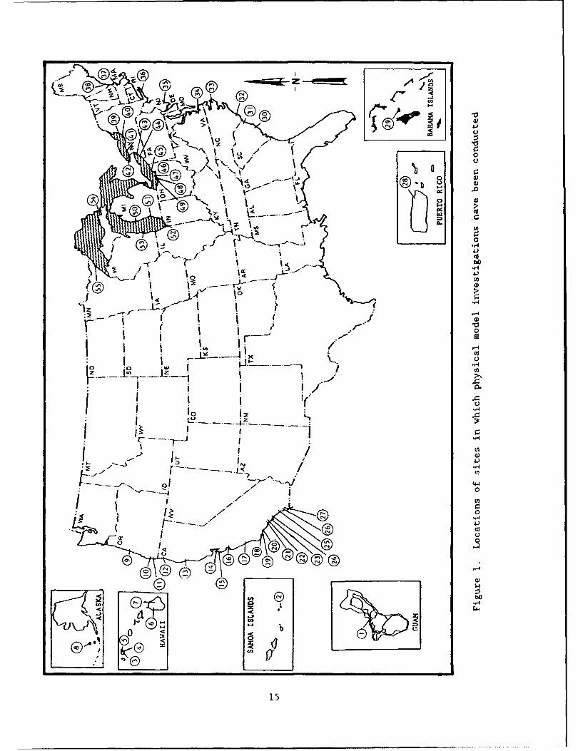
16. Physical model testing of 55 small-boat harbor projects in the
United States and/or its territories has been conducted at WES since the
1940's. These model studies have been conducted for 8 sites in Hawaii, Ameri-
can Samoa, Guam, and Alaska; 19 locations on the Pacific Coast, 1 project in
Puerto Rico, 1 in the Bahamas, 9 sites on the Atlantic Coast, and 17 locations
on the Great Lakes. The locations of these sites are shown in Figure 1.
Numbers on the figure correspond to the locations shown in the following
tabulation.
Number Location
1 Agana Small-Boat Harbor, Territory of Guam
2 Tau Harbor, Island of Tau, American Samoa
3 Waianae Small-Boat Harbor, Oahu, Hawaii
4 Kewalo Basin, Oahu, Hawaii
5 Magic Island Complex, Oahu, Hawaii
6 Kawaihae Harbor, Hawaii
7 Laupahoehoe Point, Hawaii
8 St. Paul Harbor, St. Paul Island, Alaska
9 Siuslaw River, Oregon
10 Port Orford, Oregon
11 Rogue River, Oregon
12 Crescent City Harbor, California
13 Noyo Harbor, California
14 Fisherman's Wharf, San Francisco Bay, California
15 Half Moon Bay Harbor, California
16 Monterey Harbor, California
17 Port San Luis, California
18 Santa Barbara Harbor, California
19 Ventura Harbor, California
20 Port Hueneme, California
21 Marina Del Rey, California
22 Redondo Beach King Harbor, California
23 Fish Harbor, Los Angeles, California
14
-- =a-jj z -- e4 -:
0
3S)
0 d
4-1
0
' .
0 0
GI1 I3 .,4-
A,- 00
tU
150

24 Bolsa Chica Harbor, California
25 Dana Point Harbor, California
26 Oceanside Harbor, California
27 Mission Bay Harbor, California
28 San Juan Harbor, Puerto Rico
29 Nassau Harbor, Bahamas
30 Murrells Inlet, South Carolina
31 Little River Inlet, South Carolina
32 Masonboro Inlet, North Carolina
33 Oregon Inlet, North Carolina
34 Newport News Harbor, Virginia
35 Barnegat Inlet, New Jersey
36 Shrewsbury Inlet, New York
37 Newburyport Harbor, Massachusetts
38 Wells Harbor, Maine
39 Port Ontario Harbor, New York
40 Oswego Harbor, New York
41 Hamlin Beach Harbor, New York
42 Olcott Harbor, New York
43 Cattaraugus Creek Harbor, New York
44 Barcelona Harbor, New York
45 Conneaut Harbor, Ohio
46 Geneva-on-the-Lake Small-Boat Harbor, Ohio
47 Chagrin River, Ohio
48 Edgewater Marina, Ohio
49 Vermilion Harbor, Ohio
50 Ludington Harbor, Michigan
51 New Buffalo Harbor, Michigan
52 Gary Harbor, Indiana
53 Port Washington Harbor, Wisconsin
54 Little Lake Harbor, Michigan
55 Grand Marais Harbor, Minnesota
Brief Case Histories
17. Physically modeled small-boat harbor investigations conducted at
WES are briefly examined in this portion of the report. Harbor design changes
16

resulting from the model studies are highlighted to assist in defining design
experience gained through physical modeling.
Agana Small-Boat Harbor, Territory of Guam
18. Agana Small-Boat Harbor is located on the west coast of the Island
of Guam. A shallow natural channel, created by the flow of Agana River over
the reef, provides access to two small-boat basins. A very sharp reverse bend
in the entrance channel makes navigation difficult. In addition, wave-induced
currents in the channel, particularly at the mouth, have compounded the navi-
gation problem. During the winter, high seas and swells with waves up to
12 ft in height prevent passage both in and out of the harbor.
19. Improvements to the existing harbor were required to minimize ex-
isting hazardous navigational conditions through the entrance channel and to
expand berthing capacity to meet present and future boating needs. A
1:50-scale hydraulic model was constructed and tested to determine the optimum
harbor configuration with respect to wave protection, circulation conditions,
navigation, and cost (Chatham 1975). Test waves with periods ranging from 8
to 18 sec and heights ranging from 3 to 11 ft were generated from four deep-
water directions with swl's of 0.0- and/or +2.4-ft mean lower low water
(mllw).
20. Model tests were conducted for existing conditions and 19 test plan
configurations. The originally proposed harbor design consisted of new berth-
ing areas, a revetted mole, a 350-ft-long west breakwater and a 175-ft-long
east breakwater seaward of the existing harbor. Culvert pipes, 5 ft in
diameter, were provided for harbor circulation. In addition, a sewage treat-
ment plant was proposed adjacent to the mole at two different (seaward and
shoreward) locations. The proposed plan provided wave protection in the
berthing areas, but very confused wave and current patterns existed at the
harbor entrance and circulation in the harbor basins was generally poor. As a
result of the model investigation, the west and east breakwaters were
reoriented and increased in length to 650 ft and 325 ft, respectively. This
plan (Figure 2) provided optimal navigation conditions (i.e., crosscurrents
were eliminated and wave patterns less confused). It also was determined
through the model study that an arrangement of open channels would provide
adequate circulation in the berthing areas of the harbor. Optimal channel
arrangements were developed for both (seaward and shoreward) locations of the
proposed sewage treatment plant.
17

/
Figure 2. Optimal breakwater configuration for Agana Small-Boat Harbor,
Territory of Guam
Tahu Harbor, Island of Tan, American Samoa
21. The Island of Tau' is located in the American Samoa chain. Trans-
portation of cargo and personnel between islands is accomplished by an inter-
island tug and barge network. With barges moored outside the island reefs,
loading and unloading of cargo and passengers is accomplished by means of
smaller longboats, which travel over the reefs through the "surf zone." Over-
turning of these longboats has resulted in drownings and loss of cargo. The
American Samoan government proposed small-boat harbors on each of its major
islands, and the site chosen for Taxi was on the western shore of the island.
22. A 1:50-scale hydraulic model was constructed and tested to deter-
mine the optimum harbor configuration with respect to wave protection, navi-
gation, beach protection, and cost (Crosby 1974). Test waves with periods
ranging from 6 to 18 sec and heights from 4 to 15 ft were generated from three
deepwater directions with a +2.8-ft swl mllw.
23. Model tests were conducted for 12 test plan variations of two basic
harbor designs. Each harbor configuration had a 350- by 250-ft rectangular
basin with a 100-ft-wide entrance channel and a revetted landfill. The first
18
had an entrance channel connecting the southeast corner of the basin with the
ocean, and a breakwater structure and revetted landfill to provide protection.
The second had an entrance channel connecting the southwest corner of the
basin with the ocean with a groin and a breakwater connected to a revetted
landfill providing protection.
24. Tests indicated the first basic harbor configuration ineffective in
achieving the desired wave height criteria and revealed cross currents in the
entrance channel for all test directions. It also was noted that the revetted
landfill was damaged since it was close to the edge of the reef. The second
configuration landfill was, therefore, moved 100 ft shoreward, and the sever-
ity of overtopping of the revetment was reduced. Increases in the length of
the groin resulted in reduced wave heights in the harbor, but significant
reduction of wave heights in the mooring area was not obtained. None of the
plans tested satisfied the sponsor's 3.0-ft wave height criterion in the
berthing area for all test waves. The second harbor configuration (Figure 3)
came closest to meeting the criterion but was acceptable only if recognized
that there would be periods when the harbor would not be usable. Cross cur-
rents and breaking waves were also observed in the entrance for test waves
from various directions.
Waianae Small-Boat Harbor, Oahu, Hawaii
25. Waianae is located on the west coast of the island of Oahu, Hawaii,
about 30 miles from Honolulu. The Waianae coast is an excellent boating area,
and the waters offshore provide some of the best fishing in the Hawaiian
Islands. Pokai Bay Boat Harbor served the site, however, it was frequently
shoaled in due to littoral material being trapped from the north. In addi-
tion, the harbor was severely overcrowded and there was considerable conflict
between swimmers and boaters. A new harbor was recommended at the site and
subsequently authorized by Congress.
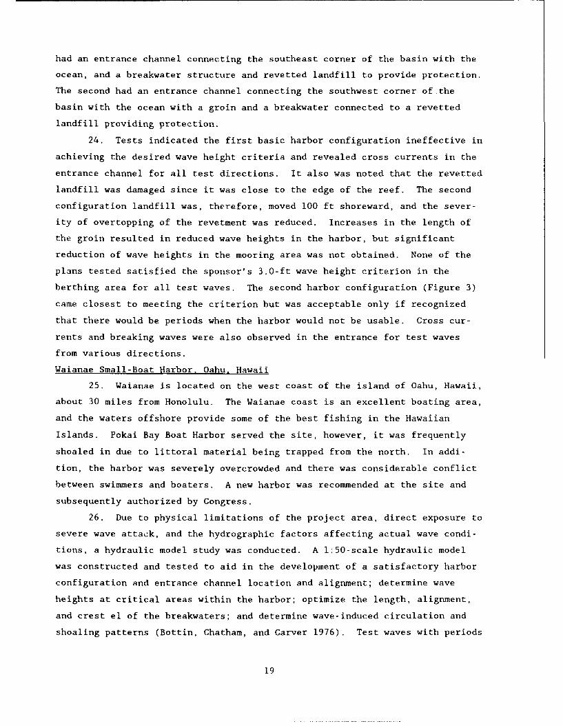
26. Due to physical limitations of the project area, direct exposure to
severe wave attack, and the hydrographic factors affecting actual wave condi-
tions, a hydraulic model study was conducted. A 1:50-scale hydraulic model
was constructed and tested to aid in the development of a satisfactory harbor
configuration and entrance channel location and alignment; determine wave
heights at critical areas within the harbor; optimize the length, alignment,
and crest el of the breakwaters; and determine wave-induced circulation and
shoaling patterns (Bottin, Chatham, and Carver 1976). Test waves with periods
19

Figure 3. Second basic harbor configuration for Tau Harbor,
American Samoa
ranging from 8 to 18 sec and heights from 4 to 12 ft were generated from four
deepwater directions with a +3.0-ft swl mllw.
27. Model tests were conducted for the existing site and 12 test plan
variations of the basic harbor design. The originally proposed harbor design
consisted of a 1,650-ft-long outer breakwater, a 150-ft-long stub breakwater,
an entrance channel, turning basin, two revetted fill areas inside the harbor,
and a boat launching ramp. Results indicated that the design met the spon-
sor's established wave height criterion of 2.0 ft in the harbor berthing
areas. It was noted that most wave energy reaching the harbor interior was
due to diffraction through the entrance rather than overtopping of, or
transmiqsion through, the breakwaters.
28. As a result of the model investigation the seaward end of the outer
breakwater was reoriented and the entire structure's crest width was reduced
from +22 ft to ±15 ft. The stub breakwater was increased in length from
150 ft to 250 ft, but its cross section was significantly reduced (from a
+15-ft crest height to +8.5 ft; from 3- to 5-ton armor stone to 800- to
1,500-1b armor; and from 15-ft crest width to 12-ft crest). Wave conditions
20
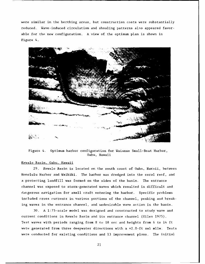
were similar in the berthing areas, but construction costs were substantially
reduced. Wave-induced circulation and shoaling patterns also appeared favor-
able for the new configuration. A view of the optimum plan is shown in
Figure 4.
Figure 4. Optimum harbor configuration for Waianae Small-Boat Harbor,Oahu, Hawaii
Kewalo Basin, Oahu, Hawaii
29. Kewalo Basin is located on the south coast of Oahu, Hawaii, between
Honolulu Harbor and Waikiki. The harbor was dredged into the coral reef, and
a protecting landfill was formed on the sides of the basin. The entrance
channel was exposed to storm-generated waves which resulted in difficult and
dangerous navigation for small craft entering the harbor. Specific problems
included cross currents in various portions of the channel, peaking and break-
ing waves in the entrance channel, and undesirable wave action in the basin.
30. A 1:75-scale model was designed and constructed to study wave and
current conditions in Kewalo Basin and its entrance channel (Giles 1975).
Test waves with periods ranging from 8 to 18 sec and heights from 6 to 14 ft
were generated from three deepwater directions with a +2.0-ft swl mllw. Tests
were conducted for existing conditions and 13 improvement plans. The initial
21
improvement plan consisted of a wave absorber along the shelf bordering the
entrance channel. It was effective in reducing wave heights in the basin but
had little effect on the strong crosscurrent patterns in the entrance.
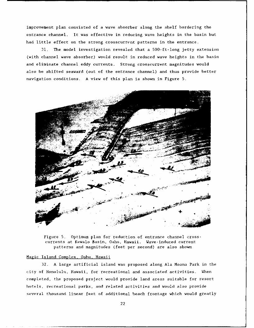
31. The model investigation revealed that a 500-ft-long jetty extension
(with channel wave absorber) would result in reduced wave heights in the basin
and eliminate channel eddy currents. Strong crosscurrent magnitudes would
also be shifted seaward (out of the entrance channel) and thus provide better
navigation conditions. A view of this plan is shown in Figure 5.
44,
Figure 5. Optimum plan for reduction of entrance channel cross-currents at Kewalo Basin, Oahu, Hawaii. Wave-induced current
patterns and magnitudes (feet per second) are also shown
Magic Island Complex, Oahu, Hawaii
32. A large artificial island was proposed along Ala Moana Park in the
city of Honolulu, Hawaii, for recreational and associated activities. When
completed, the proposed project would provide land areas suitable for resort
hotels, recreational parks, and related activities and would also provide
several thousand linear feet of additional beach frontage which would greatly
22

alleviate highly congested conditions presently existing in the Honolulu Beach
areas. The characteristics of waves and currents experienced in the area and
unknown effects of these phenomena on the proposed construction led to the
recommendation of a model investigation.
33. A 1:100-scale hydraulic model was designed and construc-ed to
develop a satisfactory circulation system through the inner lagoon to prevent
stagnation; determine the possibility of pollution in the inner lagoon due to
pollutants from a drainage canal; and study wave action in the adjacent har-
bors of Kewalo Basin and Ala Wai Boat Harbor as a result of the construction
(Brasfeild and Chatham 1967a). Test waves with periods ranging from 8 to
18 sec and heights ranging from 6 to 18 ft were reproduced from five deepwater
directions for swl's of +1.5- and/or +3.5-ft mllw.
34. Model tests were conducted for 17 test plan configurations to
develop satisfactory current conditions in the complex. The original plan
consisted of a proposed artificial island and a peninsula (Kewalo Peninsula)
west of the island. These landfills were positioned to form an inner lagoon
in the lee of the island and circulation channels between the island and the
existing Ala Wai Peninsula and the proposed Kewalo Peninsula on the east and
west sides of the island, respectively.
35. Model tests indicated that ronstruction of the proposed peninsula
would aggravate unfavorable wave conditions already existing in Kewalo Basin.
Absorbers installed along the caannel sides in conjunction with revisions to
the entrance channel (indented wave traps) were not as efficient in reducing
wave heights in the basin as absorbers alone in the entrance channel. The
optimum plan for Kewalo Basin as a result of the Magic Island complex is shown
in Figure 6.
36. The installation of the proposed Magic Island and Kewalo Peninsula
were not considered to influence wave heights in Ala Wai Boat Harbor based on
wave height tests. Model tests were conducted for expansions of the harbor,
however. A revetted mole and two additional basins were proposed. Results
indicated that undesirable wave conditions may exist in the entrances to the
newly formed basins, but can be alleviated by the addition of rubble-mound
wave absorbers at critical locations in the entrance channel (Figure 7).
Kawaihae Harbor, Hawaii
37. Kawaihae Harbor is located in Kawaihae Bay on the northwest coast
of the Island of Hawaii. A 2,650-ft-long rubble-mound breakwater was located
approximately 400 ft seaward of the harbor basin for protection from storm
23
'N. k<t
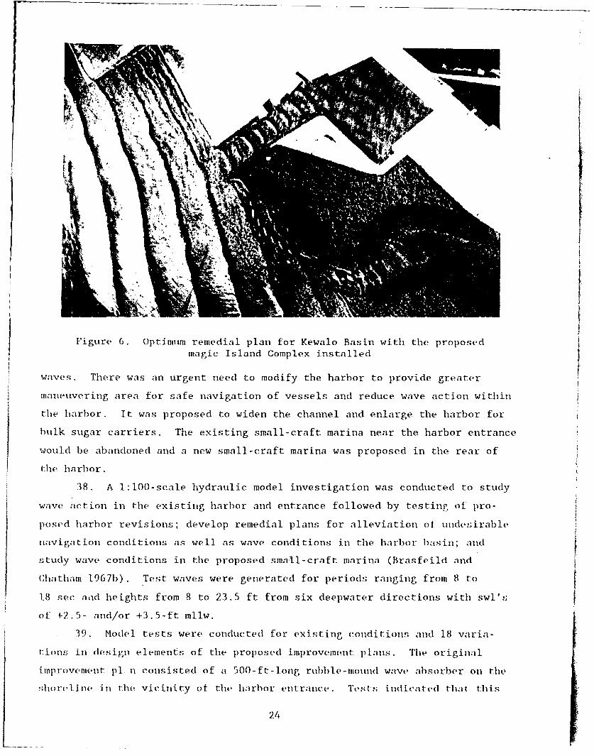
Figure 6. Optimum remedial plan for Kewalo Basin with the proposed
magic Island Complex installed $waves. There was an urgent need to modify the harbor to provide greater
maneuvering area for safe navigation of vessels and reduce wave action within
the harbor. It was proposed to widen the channel and enlarge the harbor for
bulk sugar carriers. The existing small-craft marina near the harbor entrance
would be abandoned and a new small-craft marina was proposed in the rear of
the harbor.
38. A 1:100-scale hydraulic model investigation was conducted to study
wave action in the existing harbor and entrance followed by testing ot pro-
posed harbor revisions; develop remedial plans for alleviation of undesirable
navigation conditions as well as wave conditions in the harbor basin; and fstudy wave conditions in the proposed small-craft marina (Brasfeild and
Chatham 1967b) . Test waves were generated for periods ranging from 8 to
18 sec and heights from 8 to 23.5 ft from six deepwater directions with swl's
of +2.5- and/or +3.5-ft mllw.
39. Model tests were conducted for existing conditions and 18 varia-
tions in design elements of the proposed improvement plans. The original
improvement p1 n consisted of a 500-ft-long rubble-mound wave absorber on the
shorel inm in the vicinity of the harbor entrance. TLest s indicated tihat this
24

Figure 7. Proposed expansion of Ala Wai Boat Basin with absorbersinstalled in entrances of new basins
plan offered no significant improvement over existing conditions with regard
to wave heights in the harbor. Absorber lengths up to 800 ft in conjunction
with a 750-ft-long breakwater extension were required to provide a more favor-
able wave climate in the harbor than was present with existing conditions.
The most satisfactory current conditions in the entrance were achieved, how-
ever, with a 750-ft-long breakwater extension and a new 600-ft-long shore-
connected breakwater.
40. Tests indicated that wave heights in the proposed small-boat harbor
in the rear of the basin, with a proposed 1,075-ft-long offshore structure and
a 300-ft-long shore-connected structure, would be within the sponsor's speci-
fied 1.5-ft criterion for most conditions, although this value may be exceeded
in the small-boat basin entrance. The optimum plan developed during model
study is shown in Figure 8.
Laupahoehoe Point, Hawaii
41. Laupahoehoe Point is on a peninsula on the northeast coast of the
island of Hawaii about 25 miles north-northwest of Hilo. The existing small-
craft launching ramp was unsafe due to wave energy reflecting off the adjacent
rocky shoreline and creating unacceptable conditions at the launching ramp. A
25

Figure 8. Optimum harbor improvements at Kawaihae Harbor, Hawaii
protected boat-launching ramp was needed that would allow commercial fishermen
to take full advantage of the ocean's resources in the immediate area, as well
as allow the launching of rescue boats.
42. A 1:52-scale hydraulic model was designed and constructed to deter-
mine the optimum length, alignment, crest elevations and stability of proposed
structures at the site (Bottin, Markle, and Mize 1987). Test waves (excluding
stability test conditions) with periods ranging from 6 to 14 sec and heights
ranging from 4 to 20 ft were generated from four deepwater directions with a
+2.4-ft swl mllw.
43. Model tests were conducted for 12 test plans. The original im-
provement plan consisted of an entrance channel, a turning basin, a
200-ft-long rubble-mound breakwater (seaward end having a rib cap and armored
with dolosse), and a 60-ft-long rubble wave absorber installed adjacent to the
horeline. This plan resulted in wave heights within the established 2-ft
wave height criterion (for deepwater waves of 6 ft or less) in the turning
basin about 69 percent of the time (based on hindcast data). Tests without
the wave absorber revealed that the breakwater alone was ineffective in reduc-
ing wave heights to the desired criteria. Also the length and alignment of
26
the original absorber was found to be optimum since additional wave absorber
length had little effect on further reducing wave heights in the area. Tests
also indicated that sealing of the breakwater had little effect on wave
heights in the new basin. A 50-ft extension of the proposed breakwater would
provide greater wave protection, however, this plan was cost prohibitive. The
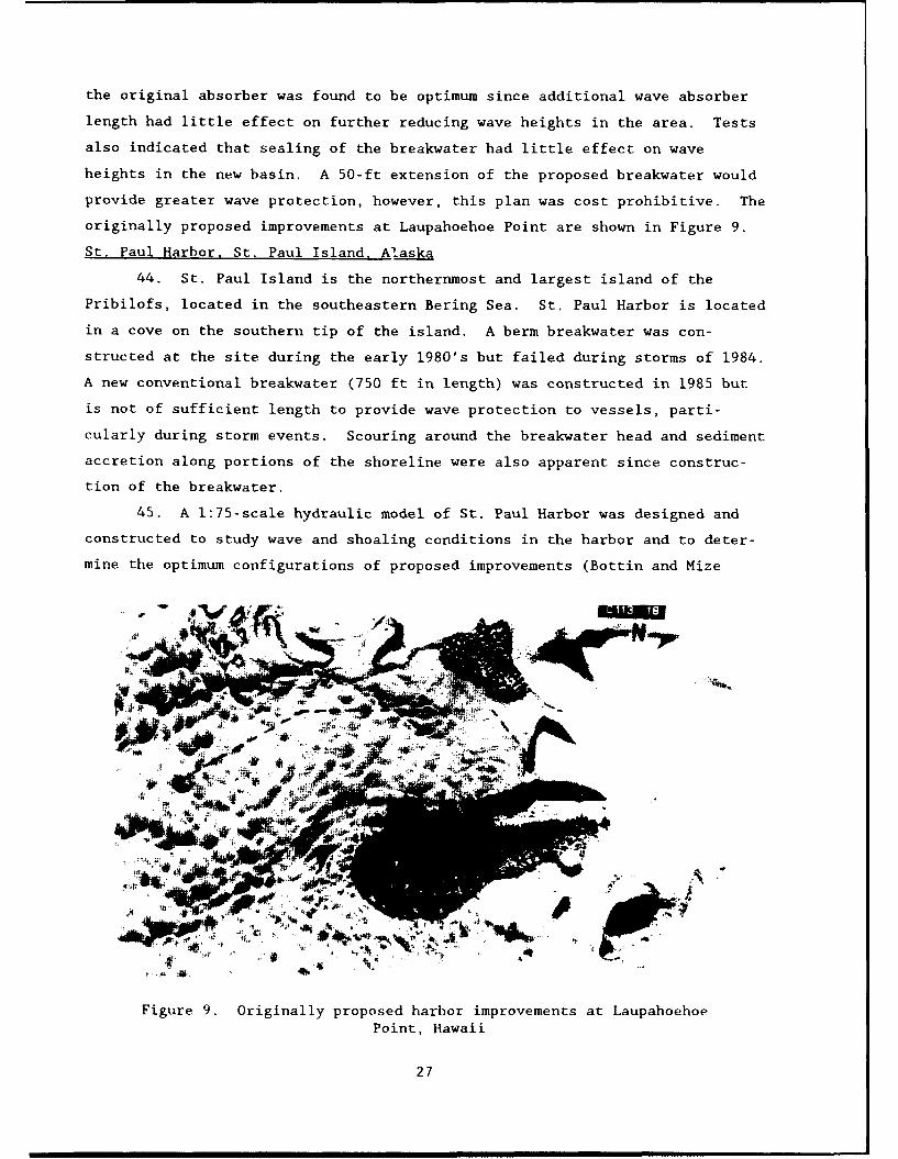
originally proposed improvements at Laupahoehoe Point are shown in Figure 9.
St. Paul Harbor, St. Paul Island, Alaska
44. St. Paul Island is the northernmost and largest island of the
Pribilofs, located in the southeastern Bering Sea. St. Paul Harbor is located
in a cove on the southern tip of the island. A berm breakwater was con-
structed at the site during the early 1980's but failed during storms of 1984.
A new conventional breakwater (750 ft in length) was constructed in 1985 but
is not of sufficient length to provide wave protection to vessels, parti-
cularly during storm events. Scouring around the breakwater head and sediment
accretion along portions of the shoreline were also apparent since construc-
tion of the breakwater.
45. A 1:75-scale hydraulic model of St. Paul Harbor was designed and
constructed to study wave and shoaling conditions in the harbor and to deter-
mine the optimum configurations of proposed improvements (Bottin and Mize
'A
4r4
40. -
Figure 9. Originally proposed harbor improvements at LaupahoehoePoint, Hawaii
27

1988). Irregular waves with periods ranging from 6 to 16 sec and heights
ranging from 7 to 25 ft were generated for test waves from five deepwater
directions with swl's of +3.2- and/or +5.0-ft mllw.
46. Model tests were conducted for existing conditions and 59 test plan
configurations. Variations entailed changes in lengths, alignments, and crest
elevations of breakwater extensions, breakwater spurs, and a secondary break-
water. The originally proposed improvement plan consisted of a 1,050-ft-long
breakwater extension and an 800-ft-long vertical dock extension. Model tests
for the proposed plan revealed wave heights of 6.8 ft along the dock, which
was more than double the sponsor's 2.5-ft wave height criterion. Sediment
tracer tests indicated accretion along the shoreline in the cove and deposits
near the head of the new breakwater. The installation of several spur and/or
secondary breakwater plans also resulted in excessive wave heights (3.5-ft
maximum) along the vertical-wall dock. Some plans reduced wave heights to an
acceptable level, but these plans were ruled unacceptable due to their narrow
entrance channel conditions which would inhibit navigation.
47. Based on the results of the model study, a pile-supported dock,
versus the vertical-wall dock, was recommended. It also was recommended that
the 2.5-ft criterion along the duck be relaxed during the most severe storm
events provided that vessels moved to other locations in the harbor which
provided acceptable wave protection.
48. The optimum improvement plan tested in the model considering wave
protection, navigation, harbor circulation, and costs included the original
1,050-ft-long breakwater extension with a detached 1,100-ft-long secondary
breakwater (Figure 10). The secondary breakwater provided wave heights of
2.5 ft or less in its lee. It was determined that the structures would have
no adverse impact on the sediment movement in the area, nor would shoaling be
induced in the harbor entrance or mooring areas.
Siuslaw River, Oregon
49. The mouth of the Siuslaw River empties into the Pacific Ocean west
of Eugene, OR. The mouth of the river is protected by jetties, however,
shoaling occurs and frequent dredging of the entrance was required. Exten-
sions of the existing jetties were authorized in 1981.
50. A 1:100-scale model study of the Siuslaw River project was con-
ducted to qualitatively determine shoaling conditions at the river mouth for
various test plans (Bottin 1981). Due to limited funds and time for the pro-
ject, testing of the proposed jetty modifications was conducted on an existing
28

4i
U I
Figure 10. Optimum configuration for St. PaulHarbor, Alaska
model of Rogue River, Oregon, which had similar offshore contours. Test waves
with periods ranging from 9 to 13 sec and heights ranging from 7 to 27 ft were
generated from two deepwater directions for swl's of 0.0- and/or +6.7-ft mllw.
Seven improvement plans were tested which included the original jetty exten-
sions and various spur arrangements attached to one or both of the extensions.
51. The original test plan consisted of 1,900- and 2,300-ft extensions
of the existing north and south jetties, respectively. With the jetty exten-
sions in place, model tests indicated that sediment would move into the en-
trance for waves from both northerly and southerly directions. To alleviate
sediment transport into the entrance channel, spurs were installed on the
jetty extensions. Model tests indicated that 400-ft-long spurs installed
900 ft shoreward of the heads of the north and south jetty extensions (Fig-
ure 11) were optimum relative to prevention of shoaling in the entrance.
Port Orford, Oregon
52. Port Orford is situated on the Pacific Coast about 50 miles north
of the Oregon-California border. The original harbor at Port Orford was
located in a natural cove, protected from waves from the North and West.
However, wave action from southwesterly winter storms frequently caused exten-
sive damage to harbor facilities. Local interests constructed a breakwater
29

Figure 11. Optimum location of jetty spurs for prevention of shoalingat Siuslaw River, Oregon
that was only partially effective with respect to wave protection, and an
extension was subsequently constructed. After completion of the breakwater
extension, the harbor area adjacent to the pier began to shoal and extensive
dredging was required.
53. A 1:100-scale hydraulic model of Port Orford Harbor was designed
and constructed to study shoaling conditions in the harbor and to develop
remedial plans to alleviate shoaling at the pier without significantly
increasing wave action at the pier (Giles and Chatham 1974). Waves with
periods ranging from 7 to 17 sec and heights ranging from 3 to 21 ft were
generated from six deepwater directions with swl's of 0.0- and/or +7.3-ft
mllw.
54. Model tests were conducted for prebreakwater conditions, existing
breakwater conditions, and 53 variations to a range of improvement plans.
Tests for prebreakwater conditions indicated wave heights along the pier in
excess of 23 ft but no sedimentation at the pier. The existing breakwater
drastically reduced wave heights at the pier for most d rections, but resulted
in sediment deposits in the harbor area for all directions due to altered
longshore currents and a large eddy in the harbor.
55. Original modifications entailed removing portions of the existing
breakwater which were generally unsuccessful. Wave heights increased at the
pier significantly with only a slight reduction in shoaling. After testing of
30

numerous additional breakwater configurations, an 1,100-ft-long structure
(Figure 12) was determined to prevent shoaling by waves from any direction,
and material already in the harbor remained stable (did not move toward the
pier). In addition, wave heights in the harbor were not increased.
Figure 12. Breakwater configuration developed forPort Orford Harbor, Oregon, for elimination of
shoal ing
Rogue River, Oregon
56. The Rogue River enters the Pacific Ocean on the Oregon coast about
30 miles north of the California border. Two jetties, spaced 1,000 ft apart,
were constructed to provide protection to the river mouth and to improve
natural flushing of the navigation channel. A small-boat basin, protected by
31
a breakwater, was located on the south bank of the river. A persistent
shoaling problem existed between the two jetties, along the inside of the
south jetty, and in the turning basin and harbor access channel. Maintenance
dredging was difficult, and the navigation channel was blocked which
restricted vessel traffic between the ocean and port facilities.
57. A 1:100-scale hydraulic model was designed and constructed (Bottin
1982b, Bottin 1983) to study wave, shoaling, current, and riverflow conditions
in the lower reaches of the Rogue River for existing conditions and numerous
improvement plans. Test waves with periods ranging from 5 to 17 sec and
heights ranging from 11 to 27 ft were generated from four deepwater directions
for swl's of 0.0-, +1.5-, +4.3-, and/or +6.7-ft mllw. Maximum ebb and flood
tidal flow conditions were simulated in the model as well as river discharges
ranging from 50,000 r 350,000 cfs.
58. Model tests were conducted for existing conditions and 59 varia-
tions to several test plans. Improvement plans consisted of dikes installed
within the existing entrance, jetty extensions (existing alignment, toward the
west, and toward the south) with and without spurs, an alternate harbor
entrance south of the river mouth, and reorieatation of the mouth of the river
with a decrease in the width of the entrance.
59. Model tests for existing conditions indicated that shoaling will
occur in the lower reaches of the river for various test waves and swl's for
each wave direction. Generally, material was deposited in the southern por-
tion of the river adjacent to the south jetty and then migrated upstream
across the entrance to the small-boat basin similar to conditions observed in
the prototype. Dikes extending from the south jetty were oriented in a
configuration that would prevent shoaling of the small-boat entrance; however,
this resulted in increased water-surface elevations upstream of the dikes.
Tests revealed that several jetty extension plans (with spurs) would prevent
sediment from entering the river entrance from the north and south shorelines,
but sediment moving down the river would eventually result in a shoal that
would extend upstream to the small-boat basin entrance. The narrower, reori-
ented river entrance resulted in shoals adjacent to the new structures that
could restrict or prohibit navigation and substantial increases in water-
surface elevations in the lower reaches of the creek. Of all the improvement
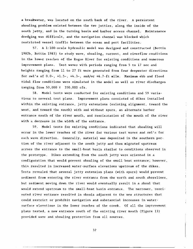
plans tested, a new entrance south of the existing river mouth (Figure 13)
provided wave and shoaling protection from all sources.
32
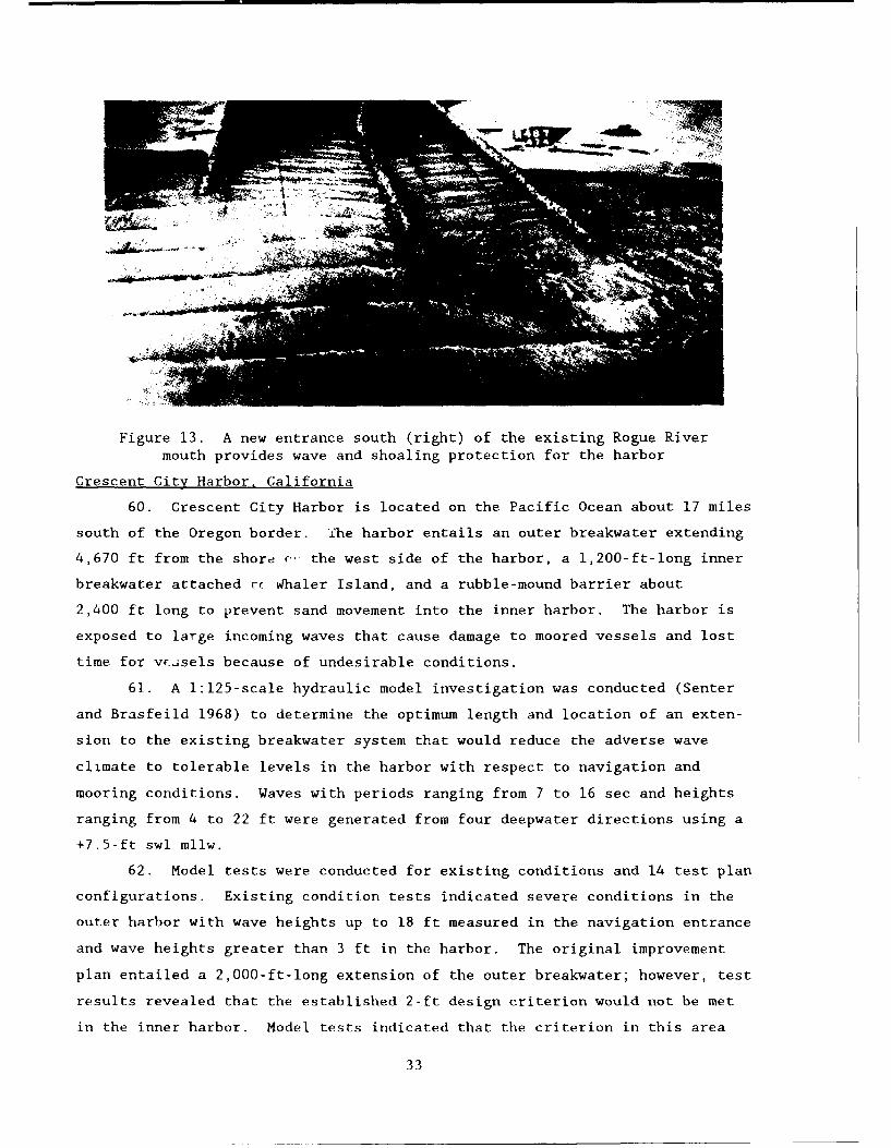
Figure 13. A new entrance south (right) of the existing Rogue Rivermouth provides wave and shoaling protection for the harbor
Crescent City Harbor, California
60. Crescent City Harbor is located on the Pacific Ocean about 17 miles
south of the Oregon border. Che harbor entails an outer breakwater extending
4,670 ft from the shore (- the west side of the harbor, a 1,200-ft-long inner
breakwater attached rc %4haler Island, and a rubble-mound barrier about
2,400 ft long to prevent sand movement into the inner harbor. The harbor is
exposed to large incoming waves that cause damage to moored vessels and lost
time for vF.jsels because of undesirable conditions.
61. A 1:125-scale hydraulic model investigation was conducted (Senter
and Brasfeild 1968) to determine the optimum length and location of an exten-
sion to the existing breakwater system that would reduce the adverse wave
climate to tolerable levels in the harbor with respect to navigation and
mooring conditions. Waves with periods ranging from 7 to 16 sec and heights
ranging from 4 to 22 ft were generated from four deepwater directions using a
+7.5-ft swl mllw.
62. Model tests were conducted for existing conditions and 14 test plan
configurations. Existing condition tests indicated severe conditions in the
outer harbor with wave heights up to 18 ft measured in the navigation entrance
and wave heights greater than 3 ft in the harbor. The original improvement
plan entailed a 2,000-ft-long extension of the outer breakwater; however, test
results revealed that the established 2-ft design criterion would not be met
in the inner harbor. Model tests indicated that the criterion in this area
33

could be met with a 400-ft-long extension of the inner breakwater. Test re-
suits showed that a 1,200-ft-long breakwater extending seaward from Whaler
Island (Figure 14), would offer improved navigation and mooring conditions in
the overall harbor, but there would be periods when the design criterion would
be exceeded. It was also determined that a rubble-mound absorber, installed
parallel to and on the harbor side of the existing outer breakwater, would
provide adequate protection from waves that overtop the present structure.
Figure 14. Breakwater configuration at Crescent City Harbor,California, provides improved overall conditions in the
harborNoyo Harbor. California
63. Noyo Harbor is located on the California coast at the mouth of Noyo
River approximately 135 miles north of San Francisco. The river empties into
Noyo Cove which is exposed to large waves from ocean storms. Waves up to
14 ft high have been observed in the cove, and conditions in the jettied river
entrance are often impassable.
64. A 1:100-scale model was designed and constructed to determine
storm-generated wave conditions along a proposed loading pier for seagoing
lumber barges with the proposed breakwater configurations installed (Wilson
1967). Waves with periods ranging from 11 to 17 sec and heights ranging from
34

14 to 26 ft were generated from four deepwater directions for a +6.9-ft swl
mllw.
65. Tests were conducted for existing conditions and 28 test plan
configurations. Model tests for existing conditions revealed wave heights up
to 17 ft at the proposed pier location during storm wave events. The original
project improvement plan included an 1,100-ft-long south breakwater and a
400-ft-long north structure. Test results, however, indicated inadequate wave
protection throughout the cove for this plan. To obtain adequate wave protec-
tion at the pier (criterion of 2.0 ft established by the sponsor), it was
determined that a 1,900-ft-long south breakwater in conjunction with a
320-ft-long north structure (Figure 15) would provide the desired wave protec-
tion in the cove. It was noted during testing that the use of rubble-wave
absorbers around the entire perimeter of the cove were not economically
justifiable based on the added wave absorption they provided.
66. Another hydraulic model investigation of Noyo River and Harbor was
conducted subsequent to the above mentioned study. A 1:75-scale model was
designed and constructed to determine the most economical breakwater configu-
ration that would provide wave protection to the existing jettied entrance
(Bottin, Acuff, and Markle 1988). Test waves with periods ranging from 7 to
19 sec and heights ranging from 6 to 32 ft were generated from five deepwater
directions with +6.2- and/or +7.0-ft swl's mllw. In addition, long-period
wave tests were conducted to determine the response of the small-boat harbor
(located upstream of the entrance) to wave periods ranging from 60 to 200 sec.
The deposition of riverine sediment in the entrance also was investigated for
river discharges ranging from 7,000 to 41,000 cfs.
67. Model tests were conducted for existing conditions and 46 test plan
configurations which included one or more breakwaters installed in the cove
west of the entrance. Variations consisted of changes in the lengths, align-
ments, and locations of the structures. For a plan to be acceptable, the
sponsor specified that maximum wave heights were not to exceed 6 ft in the
entrance and the wave was to be nonbreaking.
68. Model tests for existing conditions revealed breaking wave heights
in the entrance in excess of 10 ft for test waves from all directions. The
original improvement plan consisted of a 370-ft-long breakwater. It resulted
in wave heights in the entrance in excess of 8.5 ft. Various breakwater con-
figurations, some with up to 1,125 ft in length, were tested, and it was
determined that a 637-ft-long breakwater would result in entrance conditions
35

Figure 15. Optimum breakwater configuration at Noyo Cove, California,for wave protection of a seagoing barge loading pier
that met the established criterion. This configuration (Figure 16) did not
interfere with the passage of riverine sediment through the entrance, and it
resulted in improved long-period surge conditions in the river and harbor.
69. Additional tests were conducted in the 1:75-scale Noyo model to
develop a breakwater plan for 14-ft design waves, as opposed to waves up to
32 ft previously tested (Bottin and Mize 1989). Thirty-one test plan config-
urations were tested with various combinations of inner and outer breakwaters,
both attached and detached. The original test plan consisted of a 500-ft-long
shore-connected outer breakwater and a 400-ft-long detached inner structure
which resulted in wave heights well within the established criterion. Model
tests indicated that a 250-ft-long inner breakwater alone would provide the
required protection in the entrance for 14-ft design wave conditions from all
directions.
Fisherman's Wharf,San Francisco Bay, California
70. Fisherman's Wharf, located in San Francisco Bay near the Golden
Catp, is an area bounded on the east by Pier 45 and on the west by the
Municipal Pier. The area was essentially unprotected from wave damage.
36
Figure 16. Optimum breakwater configuration at entrance of Noý3 Riverand Harbor, California, considering all wave conditions
Wave-energy from the open ocean (entering through Golden Gate) and local
storms (waves generated by winds across the extensive water surface of the
bay) resulted in continual damage to fishing vessels and mooring facilities.
71. A 1:75-scale hydraulic model was designed and constructed (Bottin,
Sargent, and Mize 1985) to determine the most economical breakwater configura-
tion that would provide adequate short period wave protection for small craft
in the area. Test waves with periods ranging from 3.6 to 10 sec and heights
ranging from 2 to 5.8 ft were generated from six directions with swl's of 0.0-
and/or +5.7-ft mllw.
72. Model tests were conducted for existing conditions and 90 test plan
variations which consisted in changes in the lengths, alignments, and loca-
tions of proposed solid, baffled, and/or segmented breakwater structures.
Tests for existing conditions indicated wave heights up to 5.5 ft in the moor-
ing areas of the harbor. Acceptance criteria wave heights, provided by the
sponsor, were not to exceed 1.5 ft in the mooring area of a historic fleet of
vessels (along Hyde Street Pier) and 1.0 ft in the small-craft mooring areas.
73. The originally proposed improvement plan consisted of a
1,450-ft-long solid outer breakwater constructed to form a 200-ft-wide en-
trance into the harbor. This configuration was ineffective with wave heights
in excess of 4 ft measured in the small-craft mooring areas. A plan was de-
veloped that met the wave height criterion in the harbor. It consisted of a
1,585-ft-long outer solid breakwater which formed a 165-ft-wide entrance, and
37

a cu mul atieu85 t le gtPurther e a i a i nO
a f e r a w t rthe~~~~ ~o bnrnedetoo hsPafflediatceoptium reaka rfle tedwav breakwtsi o ir 5
1,58e-fami~ng te onfig rthi o ln en drgcated te ess I ave height. (,.0 ft) in
entran lidue t e l c e wave dene lo ffted baffled stru t r s~ ~ ~ O u e b r e akcn i g t i~ w a se d e v ei c htrance, and se me te r breako
edconater .
leng~ *thl n Of 40 b ea wa er
to form n a 16t'on and6. f (Piure 7). nstaled at Pier 45 withid an
harb tho f area ft Ope ing,~ 1hi ) The segmn te nd struc t Wih a d cumuft Soidv e cw in d w a vo
enisg a l l o w e d t i a
u e h d 2 8 f
harb r ae a.g ht s Plan 'net the wave acceptance no
i th o g h s~e r -wt t h ac k e h g t O f 4 .5 f t i n c i ceai n t h o g t eteentrance d ciez nt ueduring Proso t n ra
'Figure 17. Opt."mum breS kan F ra configf
r Fi h r nHalf Moo B. if harf Are 'S n F anci Igu ati n f r F7alf Hon a l Hrbor ha rf Ar e ia reakBaat Californ i a I h r a20 mialfsut Moon Bay Harbor, iso
h
4,42 -ft_,,glocta ,2 -ted h Pacific Coast about
1/2 'ni e w de It was Protected by as abouftwet brmieak a e
t 'h habrclong anda
access toe ththr or s g
taiga n entrance P o i e
.O uthll f sh n craft' Storm w es a Proah d fro'teruthesout
entered the harborthog th
38

entrance and the transmission of wave energy through the voids of the existing
breakwater frequently caused the berthing areas to be unusable.
75. A 1:100-scale hydraulic model of the harbor was designed and con-
structed to determine the optimum plan for reducing adverse wave action oc-
curring in the harbor (Wilson 1965). Waves with periods ranging from 5 to
15 sec and heights ranging from 6 to 21 ft were generated from six deepwater
directions for a +6.1-ft swl mllw.
76. Model tests were conducted for existing conditions, 11 breakwater
plan configurations consisting of extensions to the heads of both the east and
west structures, and the installation of additional offshore breakwaters.
Tests for existing conditions indicated that wave heights in the inner harbor
in excess of 2 ft would occur up to 20 percent of the time, and waves ranging
from 6 to 7 ft would occur during severe wave attack. The wave height
criterion adopted in the berthing area by the sponsor was not to exceed 2 ft
for more than a few hours per year.
77. The originally proposed improvement plan consisted of a 400-ft-long
extension of the west breakwater, reducing the entrance opening from 600 to
200 ft in width. Wave heights measured in the berthing areas exceeded the
2-ft criterion and little protection was afforded even with the narrowed en-
trance width. Further testing indicated that a 1,050-ft-long extension of the
west breakwater positioned outside the existing harbor (seaward of the en-
trance) was optimum with regard to wave protection provided and economics. A
view of the recommended configuration is shown in Figure 18.
Monterey Harbor, California
78. Monterey Harbor is located at the southern end of Monterey Bay and
is about 100 miles south of San Francisco, CA. Wharfs were originally con-
structed at the site to provide support to the local fishing fleet. Since
they were fully exposed to the weather, a 1,700-ft-long breakwater was
subsequently constructed. This structure did not provide sufficient mooring
area for the large number of boats in the harbor, and waves occasionally
caused damage to vessels and harbor facilities and mooring difficulties for
small craft in exposed areas of the harbor.
79. A 1:120-scale hydraulic model of Monterey Harbor was designed and
constructed (Chatham 1968) to determine whether proposed harbor revisions
would provide adequate protection from both long- and short-period wave and
surge action. Short-period waves with periods ranging from 7 to 17 sec and
heights ranging from 7 to 13 ft were generated from five deepwater directions
39

- -l~em '*- -- •
Zi
I•7..• • -,,- _. - -. • -•, ' - • ' !- ~ ."-•...•1. ••,-,
Figure 18. Optimum breakwater configuration recommended for HalfMoon Bay Harbor, California
with an swl of +5.2-ft mllw. Long-period waves ranging in period from 35 to
255 sec were also reproduced in the model. A maximum wave height criterion of
1.5 ft was established by the sponsor in the inner basin for short-period
tests. It was assumed that the proposed improvement plans would be satis-
factory if long-period wave heights in the existing and proposed basins did
not exceed those that occur in the existing marina.
80. Tests were conducted for existing conditions and two basic harbor
configurations (a double entrance and a single entrance). Reductions in the
length of the offshore structure also were tested for the double-entrance
plan. Short-period wave height tests for existing conditions revealed wave
heights in the berthing areas in excess of 5 ft during storm wave conditions.
It was concluded from test results that both the single-entrance and the
double-entrance plan would provide sufficient protection to the inner basins
for short-period waves, and neither plan appeared to be significantly better
than the other. Reducing the length of the offshore breakwater would have
little effect on wave heights in the basins but would result in significant
increases in wave heights in the east entrance to the harbor. It was deter-
mined from the investigation that long-period wave conditions in the harbor
would be about the same for both proposed configurations, and either plan
40
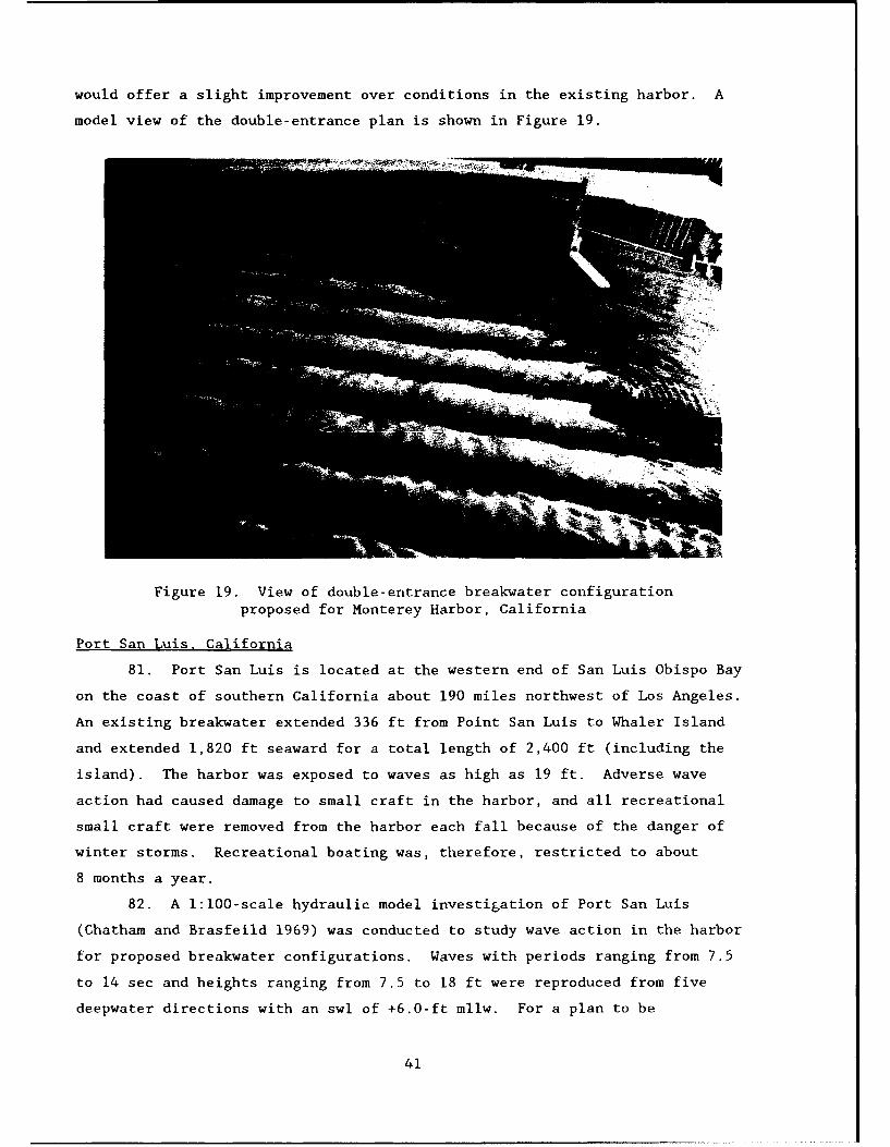
would offer a slight improvement over conditions in the existing harbor. A
model view of the double-entrance plan is shown in Figure 19.
Figure 19. View of double-entrance breakwater configurationproposed for Monterey Harbor, California
Port San Luis, California
81. Port San Luis is located at the western end of San Luis Obispo Bay
on the coast of southern California about 190 miles northwest of Los Angeles.
An existing breakwater extended 336 ft from Point San Luis to Whaler Island
and extended 1,820 ft seaward for a total length of 2,400 ft (including the
island). The harbor was exposed to waves as high as 19 ft. Adverse wave
action had caused damage to small craft in the harbor, and all recreational
small craft were removed from the harbor each fall because of the danger of
winter storms. Recreational boating was, therefore, restricted to about
8 months a year.
82. A 1:100-scale hydraulic model investigation of Port San Luis
(Chatham and Brasfeild 1969) was conducted to study wave action in the harbor
for proposed breakwater configurations. Waves with periods ranging from 7.5
to 14 sec and heights ranging from 7.5 to 18 ft were reproduced from five
deepwater directions with an swl of +6.0-ft mllw. For a plan to be
41
acceptable, it was specified by the sponsor that waves were not to exceed
2.5 ft in the boat mooring area and 1.5 ft in the slip areas.
83. Tests were conducted for existing conditions and 26 test plan con-
figurations. Test results for existing conditions revealed wave heights up to
19 ft in the proposed mooring area, indicating that considerable protection
was needed for suitable anchorage and mooring of small craft. The originally
proposed improvement plan consisted of an 1,150-ft-long south breakwater with
a 370-ft-long wing extending northward from the structure, a 3,515-ft-long
detached breakwater, and a 1,300-ft-long north breakwater that 'was shore-
connected. The plan resulted in significant wave height reductions in the
harbor (up to 85 percent when compared to existing conditions).
84. Numerous modifications were made to the originally proposed break-
water configuration. Tests indicated that the proposed 1,300-ft-long north
breakwater and the 370-ft-long south breakwater wing could be replaced by
revetted fills. The detached breakwater orientation was adequate, but the
crest elevation could be reduced on the southern portion, and the south break-
water was increased to 1,550 ft in length. A view of the optimum improvement
plan is shown in Figure 20. Except for a very small percentage of the time,
wave height acceptance criteria should be met with the recommended plan in
place.
Santa Barbara Harbor, California
85. Santa Barbara Harbor is located on the Southern California coast
about 90 miles northwest of Los Angeles. The harbor is in the lee of an
1,800-ft-long rubble-mound breakwater, covers about 44 acres in area, and
accommodates about 700 small-craft vessels. The harbor is exposed to direct
wave action from several deepwater directions. Sediment migrates along the
existing breakwater and is deposited in the lee of its eastern end and con-
stant dredging is required. Plans were formulated to expand and improve the
small-craft harbor by enclosing the area by a breakwater system.
86. A 1:100-scale hydraulic model was designed and constructed
(Brasfeild and Ball 1967) to investigate wave action in the harbor for the
proposed breakwater configurations. Waves with periods ranging from 8 to
16 sec and heights ranging from 8 to 18 ft were reproduced from four wave
directions using a +6.0-ft swl mllw. For a plan to be acceptable, the sponsor
specified that wave heights were not to exceed 1.5 ft in the small boat basin
mooring areas
42

Figure 20. Optimum breakwater configuration developed for Port SanLuis, California
87. Tests were conducted for 16 test plan variations. The originally
proposed improvement plan consisted of a 500-ft-long extension of the existing
(west) breakwater, a 3,600-ft-long shore-connected east breakwater, a
1,600-ft-long detached breakwater, a sand trap area, and three moles in the
harbor that provided four mooring basins. Variations consisted of changes in
the lengths, alignments, locations, crest elevations, and slopes of the
breakwaters.
88. The wave height criterion was met for the original breakwater con-
figuration; however, based on test results, modifications were made to the
structures that significantly reduced costs. As a result of the study, the
detached breakwater was reduced from 1,600 to 1,400 ft in length, the crest
elevation of the west breakwater extension was reduced from +16 to +12 ft, the
crest elevation of the westward 800-ft length of the detached breakwater was
reduced from +16 to +12 ft, and the seaward slope at the corner of the east
breakwater was flattened to reduce wave runup and eliminate overtopping that
occurred at that location. A view of this plan configuration is shown in
Figure 21. In addition, it was determined that the detached breakwater could
be extended to 1,735 ft in length, with the west end reoriented to provide a
larger sand trap and still provide adequate wave protection in the harbor
basins.
43
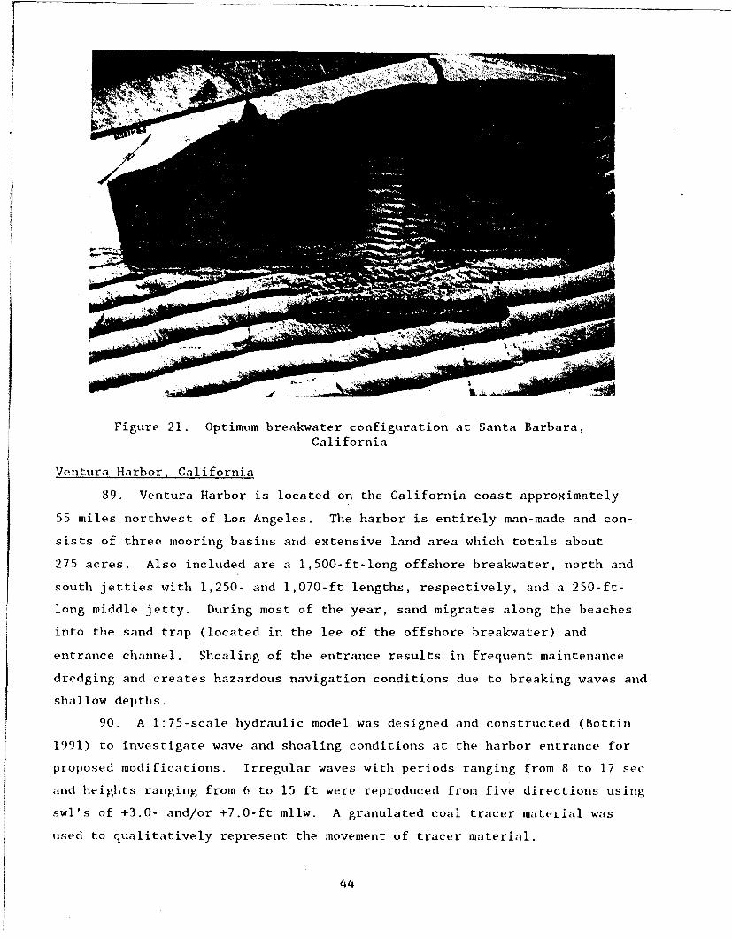
Figure 21. Optimum breakwater configuration at Santa Barbara,California
Ventura Harbor, California
89. Ventura Harbor is located on the California coast approximately
55 miles northwest of Los Angeles. The harbor is entirely man-made and con-
sists of three mooring basins and extensive land area which totals about
275 acres. Also included are a 1,500-ft-long offshore breakwater, north and
south jetties with 1,250- and 1,070-ft lengths, respectively, and a 250-ft-
long middle jetty. During most of the year, sand migrates along the beaches
into the sand trap (located in the lee of the offshore breakwater) and
entrance channel. Shoaling of the entrance results in frequent maintenance
dredging and creates hazardous navigation conditions due to breaking waves and
shallow depths.
90. A 1:75-scale hydraulic model was designed and constructed (Bottin
1991) to investigate wave and shoaling conditions at the harbor entrance for
proposed modifications. Irregular waves with periods ranging from 8 to 17 sec
and heights ranging from 6 to 15 ft were reproduced from five directions using
swl's of +3.0- and/or +7.0-ft mllw. A granulated coal tracer material was
used to qualitatively represent the movement of tracer material.
44
91. Model tests were conducted for existing conditions and 11 test plan
configurations. Improvement plans consisted of an extension of the existing
detached breakwater, a new south beach groin, a spur groin extending from the
existing north jetty, and additional channel dredging. Variations entailed
changes in the length, alignment, and location of the proposed north spur
groin. Testing of existing conditions indicated excessive wave heights in the
entrance channel for waves from westerly direction and very heavy tracer de-
posits in the entrance channel for waves from the northerly and southerly
directions.
92. The originally proposed detached breakwater extension was effective
in reducing wave heights in the entrance to acceptable levels, and the pro-
posed south beach groin provided shoaling protection to the entrance for waves
from the south. The proposed spur groin (250 ft long) attached to the exist-
ing north jetty, however, resulted in heavy deposits in the entrance channel
for waves from northwesterly directions. Model tests revealed that the spur
groin could be reoriented and lengthened (300 ft long) to minimize shoaling of
the entrance channel. The spur groin created eddies over the deposition basin
in the lee of the offshore breakwater in which most of the sediment deposited.
A view of the optimum plan is shown in Figure 22.
Port Hueneme, California
93. The Port of Hueneme is situated on the coast of Southern
California, approximately 65 miles northwest of the Los Angeles-Long Beach
port complex. Harbor dredging and construction of dock facilities were com-
pleted in 1940 and were taken over by the Navy in 1942. In 1961 the original
wharf and adjacent land was sold by the Navy to the Oxnard Harbor District.
The harbor was dredged through the shoreline and had an east and west break-
water which protected the entrance. To accommodate rapid growth, the harbor
commission proposed an expansion to the east basin of the harbor.
94. A 1:100-scale hydraulic model investigation was conducted to
determine the effects of the proposed revision on mooring conditions in the
harbor resulting from long-period waves (Crosby, Durham, and Chatham 1975).
Prototype wave periods ranging from 30 to 230 sec at 5-sec intervals were
generated from one direction (representing several deepwater directions) with
a +5.4-ft swl mllw.
95. Tests were conducted for existing conditions and the proposed basin
expansion which consisted of a 710- by 450-ft-rectangular extension to the
existing east basin. A comparison of test results for existing conditions and
45

" N
Figure 22. Sediment tracer patterns for optimum improvement planat Ventura Harbor, California
the basin extension revealed that the proposed basin will not alter the major
oscillation patterns of the harbor for wave periods less than 130 sec, and for
periods greater than 130 sec, effects should be minimal. Wave heights versus
frequency response in the expanded harbor will generally be equal to or less
than those for the existing harbor. The model also indicated that expansion
of the east basin would not produce significant changes in mooring conditions
encountered in the present harbor. A general view of existing conditions in
the model is shown in Figure 23.
Marina del Rey, California
96. Marina del Rey is a small-craft harbor located in Santa Monica Bay
about 15 miles southwest of Los Angeles, CA. The marina was developed by
dredging a 2-mile-long channel and eight lateral basins off the main channel.
The entrance was protected by two 'jetties extending about 2,000 ft into the
hay. After construction of the harbor, waves entering the wide entrance chan-
nel reflected oft the vertical concrete perimeter walls of the channel and
resulted in intolerable wave conditions in several of the basins.
46
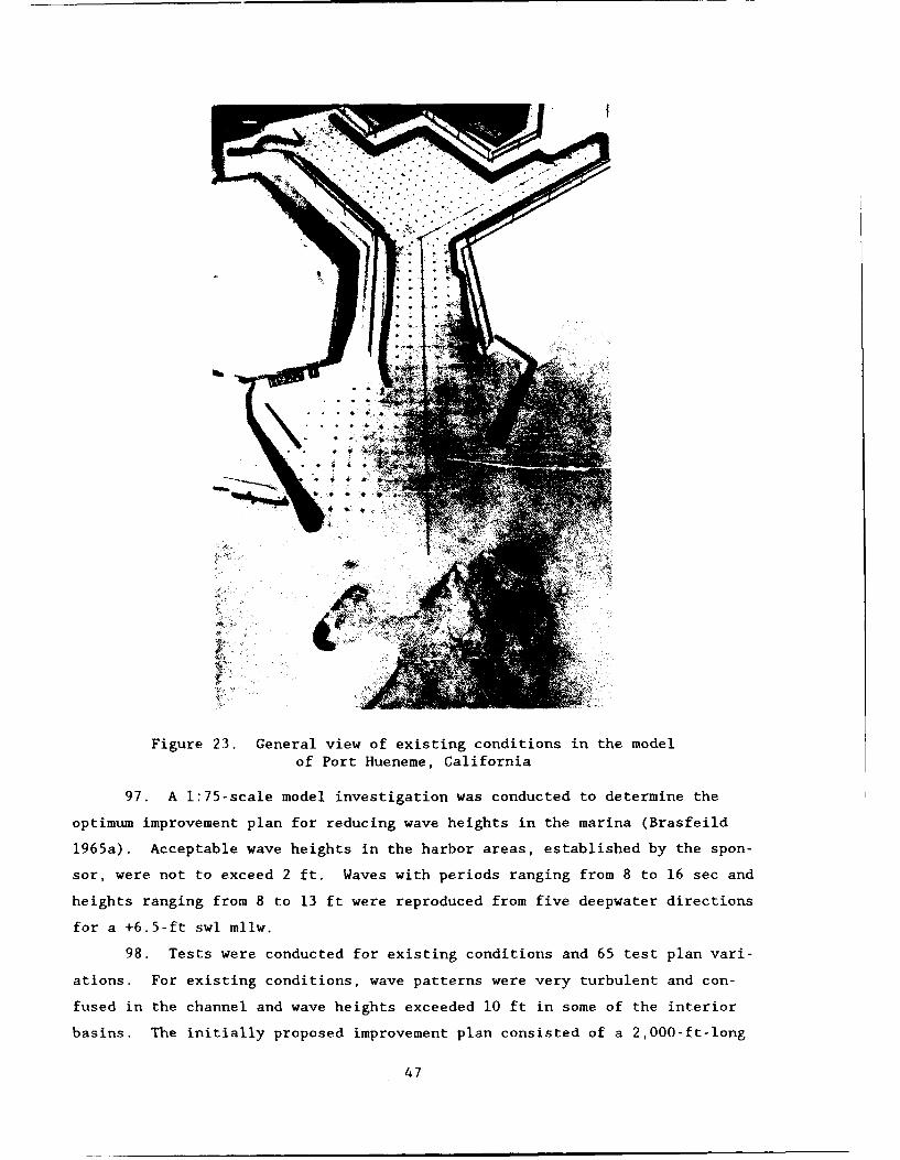
Figure 23. General view of existing conditions in the modelof Port Hueneme, California
97. A 1:75-scale model investigation was conducted to determine the
optimum improvement plan for reducing wave heights in the marina (Brasfeild
1965a). Acceptable wave heights in the harbor areas, established by the spon-
sor, were not to exceed 2 ft. Waves with periods ranging from 8 to 16 sec and
heights ranging from 8 to 13 ft were reproduced from five deepwater directions
for a +6.5-ft swl mllw.
98. Tests were conducted for existing conditions and 65 test plan vari-
ations. For existing conditions, wave patterns were very turbulent and con-
fused in the channel and wave heights exceeded 10 ft in some of the interior
basins. The initially proposed improvement plan consisted of a 2,000-ft-long
47
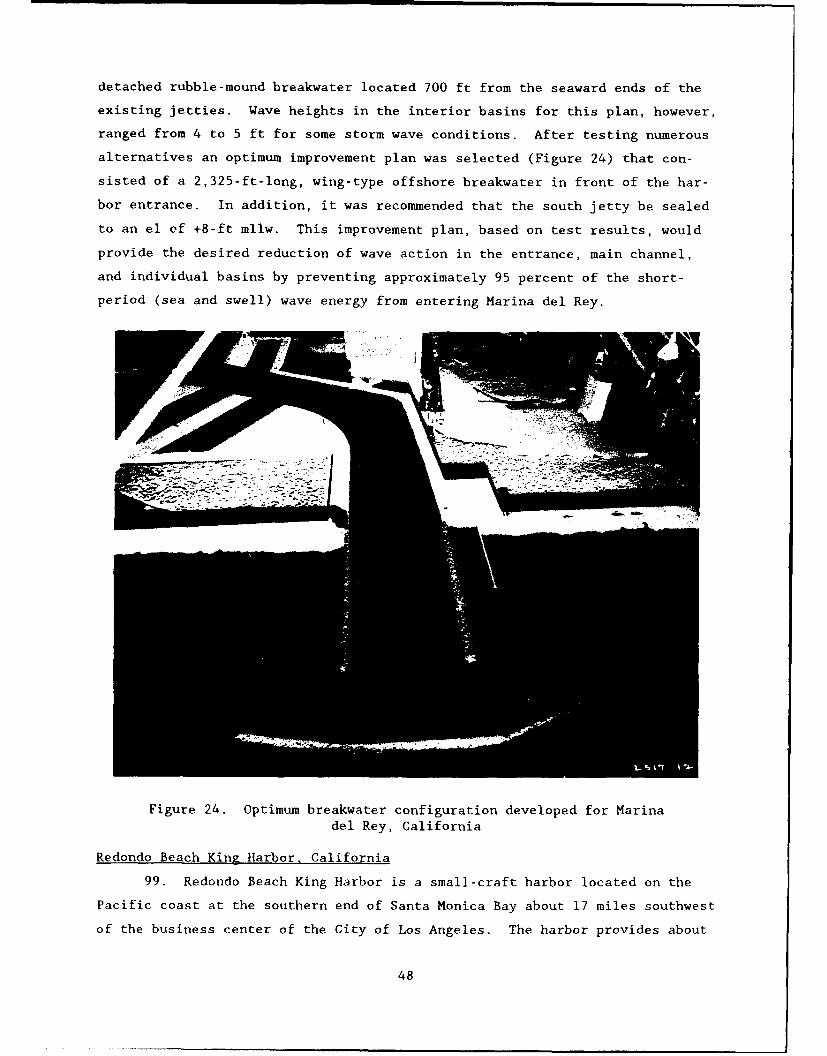
detached rubble-mound breakwater located 700 ft from the seaward ends of the
existing jetties. Wave heights in the interior basins for this plan, however,
ranged from 4 to 5 ft for some storm wave conditions. After testing numerous
alternatives an optimum improvement plan was selected (Figure 24) that con-
sisted of a 2,325-ft-long, wing-type offshore breakwater in front of the har-
bor entrance. In addition, it was recommended that the south jetty be sealed
to an el of +8-ft mllw. This improvement plan, based on test results, would
provide the desired reduction of wave action in the entrance, main channel,
and individual basins by preventing approximately 95 percent of the short-
period (sea and swell) wave energy from entering Marina del Rey.
Figure 24. Optimum breakwater configuration developed for Marinadel Rey, California
Redondo Beach King Harbor, California
99. Redondo Beach King Harbor is a small-craft harbor located on the
Pacific coast at the southern end of Santa Monica Bay about 17 miles southwest
of the business center of the City of Los Angeles. The harbor provides about
48

1,600 boat slips in three basins and is protected by a 4,285-ft-long north
breakwater and a 600-ft-long south structure. The outer 1,600 ft of the north
structure is low-crested (+14-ft mllw) while the remainder of the breakwater
has a +20-ft crest el. During storms, energy of waves overtopping and trans-
mitting through the structures and passing through the harbor entrance results
in adverse conditions in the harbor, particularly in the lee of the low-
crested section.
100. A 1:75-scale hydraulic model investigation was conducted to evalu-
ate the adequacy of proposed improvement plans with regard to desired storm
wave protection levels (Bottin and Mize 1990). Wave height criteria varied in
the harbor for various return periods. Waves with periods ranging from 8 to
20 sec and heights ranging from 8 to 22.4 ft were reproduced by a spectral
wave generator from three directions for swl's of +7.0- and/or +8.0-ft mllw.
101. Tests were conducted for existing conditions and 14 test plan
configurations. Wave heights for existing conditions indicated very rough and
turbulent wave conditions in the harbor with wave heights up to 8 ft along the
moles for 50-year conditions (sponsor acceptance criterion was 3 ft for these
conditions). The originally proposed improvement plan consisted of raising a
1,300-ft-long portion of the low-crested north breakwater to +20 ft and ex-
tending the south breakwater 300 ft. For this improvement plan, wave heights
were in excess of the established criteria seaward of the moles. An optimum
plan was developed which involved raising (to +20 ft) and sealing the
1,300-ft-long portion of the low-crested north breakwater. The structure was
sealed by overlaying the harbor side of the breakwater with 200- to 2,000-lb
stone gradation which was then capped with 11- to 19-ton armor stone. In
addition, the south breakwater was extended 150 ft and a 300-ft-long portion
around the dogleg was raised 4 ft (el +16). The optimum improvement plan is
shown in Figure 25.
102. Additional tests were conducted in the 1:75-scale Redondo Beach
King Harbor model to study wave conditions avd determine the adequacy of pro-
posed improvement plans in the northern portion of the harbor at Mole A
(Bottin and Kent 1990). Test results for existing conditions indicated severe
overtopping of the breakwater and subsequent flooding of Mole A. The original
improvement plan entailed raising a 200-ft-long portion of the breakwater and
flattening the slope of the structure on the sea side of Mole A. Model tests
indicated that additional stone was required on an additional 150-ft-long
portion of the breakwater to minimize overtopping and flooding of the mole.
49

Figure 25. Optimum breakwater plan developed for Redondo Beach
King Harbor, California
Fish Harbor, Los Angeles, California
103. Fish Harbor is located within Los Angeles Harbor, California,
about 2 miles north-northwest of Angel's Gate. Many of the waterfront struc-
tures required replacement due to deterioration and obsolescence, and unfavor-
able wave conditions during storms prevented the expansion of small-boat
moorings. Improvements proposed for the harbor included removing some of the
existing breakwaters, deepening of the basins, excavating portions of land in
the harbor, creating new landfills, and installing new breakwaters to provide
protection for small craft during storm wave events.
104. A 1:60-scale hydraulic model was designed and constructed to de-
termine breakwater modifications required to provide short-period wave protec-
tion for the proposed development project. Test-wave periods and heights
ranging from 4 to 19 sec and 2 to 7 ft, respectively, were generated from two
wave directions using a +5.4-ft swl mllw.
105. Tests were conducted for existing conditions and 18 test plan
variations of the improvement plan. Test results for existing conditions
revealed rough and turbulent wave conditions in the harbor with wave heights
in excess of 4 ft in the mooring areas of the outer harbor and 3 ft in the
inner harbor. For a plan to be acceptable, wave heights were not to exceed
1.5 ft in the commercial fishing basin and 1.0 ft in the recreational boating
area. The original improvement plan resulted in wave heights in excess of
3.0 ft along a vertical-wall portion of the newly developed harbor. Various
channel alignments, spur lengths, and absorbers were tested. After further
50

evaluation, a 200-ft-long breakwater spur attached to the breakwater at a
point 700 ft seaward of the vertical wall (Figure 26) was developed as the
optimal plan. It met the sponsor's established criteria and provided a future
area of expansion for small craft in the lee of the breakwater.
Figure 26. Optimum breakwater configuration for Fish Harbor,Los Angeles, California
Bolsa Chica Harbor, California
106. Bolsa Chica is located on the Pacific coast south of Long Beach,
CA. An ocean entrance project with an associated marina complex was proposed
at Bolsa Bay. Both navigable and nonnavigable ocean entrance concepts were
being considered for construction.
107. A 1:75-scale hydraulic model investigation was conducted (Bottin
and Acuff 1989) to determine wave penetration into the marina basin; to study
circulation and sediment transport paths in the vicinity of the proposed
structures; and to assess the entrance channel and jetty design configurations
for both the navigable and nonnavigable ocean entrance concepts. In addition,
the effects of flood flows entering the marina complex from Wintersburg Chan-
nel were determined. Waves with periods ranging from 5 to 17 sec and heights
ranging from 7 to 15 ft were reproduced by a spectral wave generator for five
51
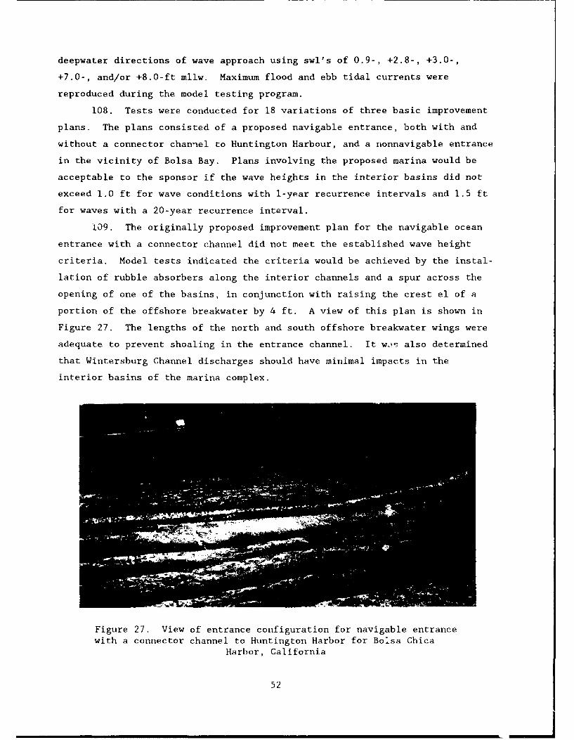
deepwater directions of wave approach using swl's of 0.9-, +2.8-, +3.0-,
+7.0-, and/or +8.0-ft mllw. Maximum flood and ebb tidal currents were
reproduced during the model testing program.
108. Tests were conducted for 18 variations of three basic improvement
plans. The plans consisted of a proposed navigable entrance, both with and
without a connector channel to Huntington Harbour, and a nonnavigable entrance
in the vicinity of Bolsa Bay. Plans involving the proposed marina would be
acceptable to the sponsor if the wave heights in the interior basins did not
exceed 1.0 ft for wave conditions with 1-year recurrence intervals and 1.5 ft
for waves with a 20-year recurrence interval.
109. The originally proposed improvement plan for the navigable ocean
entrance with a connector channel did not meet the established wave height
criteria. Model tests indicated the criteria would be achieved by the instal-
lation of rubble absorbers along the interior channels and a spur across the
opening of one of the basins, in conjunction with raising the crest el of a
portion of the offshore breakwater by 4 ft. A view of this plan is shown in
Figure 27. The lengths of the north and south offshore breakwater wings were
adequate to prevent shoaling in the entrance channel. It w,-t also determined
that Wintersburg Channel discharges should have minimal impacts in the
interior basins of the marina complex.
Figure 27. View of entrance configuration for navigable entrancewith a connector channel to Huntington Harbor for Bolsa Chica
Harbor, California
52

110. The originally proposed improvement plan with the navigable ocean
entrance without a connector channel did not meet the specified criterion in
the interior basins. Variations were tested that made the plan acceptable.
It was determined that removal of 750 ft or more of the north wing or 250 ft
of the south wing of the offshore breakwater would result in sediment deposits
in the entrance to the complex.
111. Tests conducted for the nonnavigable ocean entrance plan indicated
5- to 7-ft waves in the entrance during storm wave conditions. Some sediment
along the shoreline and in the breaker zone will bypass the new entrance, and
some will penetrate into the channel for waves from all directions.
Dana Point Harbor. California
112. Dana Point, California, located on the Southern California coast
about 40 miles southeast of the Los Angeles-Long Beach Harbors, was the site
of a proposed small-boat harbor. The harbor was proposed in a sheltered cove
in the lee of Dana Point. After development, the proposed harbor 7ould en-
close an area of about 210 acres and provide berthing facilities for about
2,150 small boats. The cove is exposed to storm waves from directions ranging
from southwest counterclockwise to south-southeast and to ocean swells from
the south. The proposed harbor would be subjected to damaging wave energy
reaching the berthing areas by entering through the outer navigation entrance
and being transmitted through and/or overtopping the proposed rubble-mound
breakwaters.
113. A 1:100-scale hydraulic model investigation was conducted to de-
termine the optimum breakwater plan and location and size of the navigation
opening that would provide adequate protection for the mooring areas during
storm wave activity (Wilson 1966). Waves with periods ranging from 9 to
18 sec and heights ranging from 8 to 18 ft were generated from eight deepwater
directions using an swl of +6.7-ft mllw. A wave height acceptance criterion
of 1.5 ft was established in the harbor berthing areas by the sponsor and
waves in the fairway were not to exceed 4 to 5 ft.
114. Tests wece conducted for exiscing conditions and 13 test plans.
Results for existing conditions indicated rough and turbulent conditions in
the area even for low-magnitude storm waves. The proposed improvement plan
involved construction of outer breakwaters and inner-harbor development con-
sisting of east and west basin berthing areas partially enclosed by the shore-
line on the north and a mole section on the south, southeast, and southwest
53
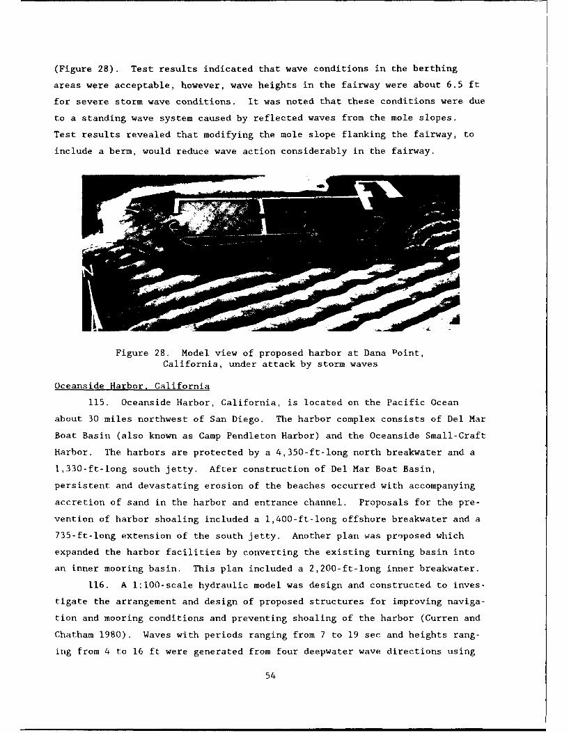
(Figure 28). Test results indicated that wave conditions in the berthing
areas were acceptable, however, wave heights in the fairway were about 6.5 ft
for severe storm wave conditions. It was noted that these conditions were due
to a standing wave system caused by reflected waves from the mole slopes.
Test results revealed that modifying the mole slope flanking the fairway, to
include a berm, would reduce wave action considerably in the fairway.
Figure 28. Model view of proposed harbor at Dana Point,California, under attack by storm waves
Oceanside Harbor, California
115. Oceanside Harbor, California, is located on the Pacific Ocean
about 30 miles northwest of San Diego. The harbor complex consists of Del Mar
Boat Basin (also known as Camp Pendleton Harbor) and the Oceanside Small-Craft
Harbor. The harbors are protected by a 4,350-ft-long north breakwater and a
1,330-ft-long south jetty. After construction of Del Mar Boat Basin,
persistent and devastating erosion of the beaches occurred with accompanying
accretion of sand in the harbor and entrance channel. Proposals for the pre-
vention of harbor shoaling included a 1,400-ft-long offshore breakwater and a
735-ft-long extension of the south jetty. Another plan was proposed which
expanded the harbor facilities by converting the existing turning basin into
an inner mooring basin. This plan included a 2,200-ft-long inner breakwater.
116. A 1:100-scale hydraulic model was design and constructed to inves-
tigate the arrangement and design of proposed structures for improving naviga-
tion and mooring conditions and preventing shoaling of the harbor (Curren and
Chatham 1980). Waves with periods ranging from 7 to 19 sec and heights rang-
ing from 4 to 16 ft were generated from four deepwater wave directions using
54

swl's of 0.0- and +5.4-ft mllw. With regard to wave conditions, wave heights
in the berthing areas of the harbor expansion and in the expansion entrance
were not to exceed 1.5 and 4.0 ft, respectively.
117. Tests were conducted for existing conditions and 88 test plan
variations consisting of changes in the lengths and alignments of the break-
water structures and jetty extensions, changes in the north jetty cross sec-
tion, the addition of an additional small-craft basin, and the construction of
sand traps. Existing conditions revealed rough and turbulent wave conditions
in the entrance channel due to waves breaking on the shoal across the harbor
entrance, diffracting around the jetties, and overtopping the north jetty.
Strong longshore currents were observed which contributed to hazardous en-
trance conditions. Tracer tests indicated that the model accurately
reproduced general sediment patterns observed in the prototype.
118. Test results for the originally proposed improvement plan indicat-
ed that the offshore breakwater was ineffective in trapping sediment outside
the harbor entrance and contributed to the shoaling problem by trapping mate-
rial in the entrance channel. This plan was ineffective in reducing wave
heights in the harbor expansion to the desired levels. Model tests indicated
that stub groins and 500-ft radii sand traps located at strategic locations
adjacent to the north breakwater and south jetty would minimize shoaling in
the entrance for all wave directions and water levels. Extensions of the
north breakwater and south jetty, with a stub groin installed on the south
jetty, would result in wave heights within the established criteria. Typical
wave and shoaling patterns at the harbor entrance are shown in Figure 29.
Mission Bay Harbor, California
119. Mission Bay Harbor is located on the coast of Southern California,
about 10 miles north of San Diego Bay. The harbor entrance, leading to
several coves and basins, was protected by two jetties (designated north and
middle jetty) which extended into the bay about 3,800 and 4,600 ft, respec-
tively. The harbor accommodated about 1,900 small boats, consisting entirely
of recreational and sport fishing craft. The harbor is exposed to wind waves
from deepwater directions, northwest counterclockwise through south. During
storms (with incident waves larger than 10 ft in height) undesirable wave
action and vessel damage occurred in Quivera Basin and Glen Rick Cove (located
inland of the shoreward ends of the jetties).
55

Figure 29. Wave and shoaling patterns at Oceanside Harbor entrance for
improvement plan with waves from south
120. A 1:100-scale hydraulic model investigation was conducted to de-
termine wave effects in the existing harbor and to test and develop improve-
ment plans proposed for reducing wave heights within Quivera Basin and Glen
Rick Cove to satisfactory levels (Ball and Brasfeild 1969). Waves with peri-
ods ranging from 7 to 19 sec and heights of 9 to 19 ft were reproduced from
seven deepwater directions using a +5.4-ft swl mllw.
121. Tests were conducted for existing conditions and eight improvement
plans. For existing conditions, wave heights of 1.7 and 2.9 ft were obtained
in Quivera Basin and Glen Rick Cove, respectively. The originally proposed
improvement plan entailed impervious vertical structures that reduced the
widths of both basins by 50 percent. This plan resulted in only slight wave
height reductions in the basins. Model tests revealed that modifications were
required to the south bank of the entrance channel. The existing curved por-
tion of the bank line was revised to a series of right-angle steps that ex-
tended to the Quivera Basin entrance (Figure 30). This test plan resulted in
an overall reduction in wave heights of approximately 79 percent in Glen Rick
Cove anod 23 perc•ent in Quivera Basin.
56
Mpg.

Figure 30. Optimum development of southern bankline atMission Bay Harbor, California
122. Another hydraulic model investigation of Mission Bay Harbor was
conducted subsequent to the previously mentioned study. A 1:100-scale model
was designed and constructed to investigate the arrangement and design of
proposed structures for improving hazardous entrance conditions and reducing
surge inside the harbor (Curren 1983). Test waves with periods ranging from 7
to 19 sec and heights ranging from 5 to 15 ft were reproduced from three deep-
water directions with swl's of 0.0-, +2.7-, and/or +5.4-ft mllw. In addition,
long-period wave tests were conducted to determine surge conditions in the bay
for wave periods ranging from 30 to 140 sec. Maximum flood and ebb tidal
flows through the bay also were reproduced during the testing program.
123. Model tests were conducted for existing conditions and 30 test
plan configurations which entailed changes in the lengths, alignments, and
cross sections of proposed offshore breakwaters. For an improvement plan to
be acceptable, the sponsor specified that maximum wave heights in the harbor
entrance between the jetties were not to exceed 1.5 ft for deepwater waves of
6 ft or less. The originally proposed improvement plan consisted of a
2,200-fr-long offshore breakwater with a +22.5-ft crest el positioned 900 ft
57

seaward of the harbor entrance. The plan also included the removal of 220 ft
from the end of the existing north jetty. Test results revealed the criterion
in the entrance would not be met with this test plan. After evaluation of
numerous alternatives a plan was developed (Figure 31) which consisted of a
1,600-ft-long offshore breakwater installed 525 ft offshore with a +17.5-ft
crest el and an impervious core to a +7.5-ft el (original core was el
-12.5 ft). Concurrent removal of 230 ft of the north jetty was included.
This plan provided acceptable wave protection in the harbor entrance. In
addition, long-period harbor oscillation tests indicated that the breakwater
effectively reduced long-period energy in the harbor. In most cases, the
selected improvement plan reduced resonant peaks by 50 percent or more when
compared to existing conditions.
Figure 31. View of optimum entrance proteztion plan atMission Bay Harbor, California
124. Additional tests were conducted in the second model for improving
hazardous entrance wave conditions and reducing surge inside t1__ harbor while
minimizing impacts on surfing (Bottin and Acuff 1985). Wave heights in the
entrance were relaxed from 1.5 to 4.0 ft for incident waves of 6 ft or less
for these tests. Model tests were conducted for 10 variations in the design
elements of three basic harbor configurations. The optimum plan, considering
wave protection, ease of navigation, and economics, consisted of a
58
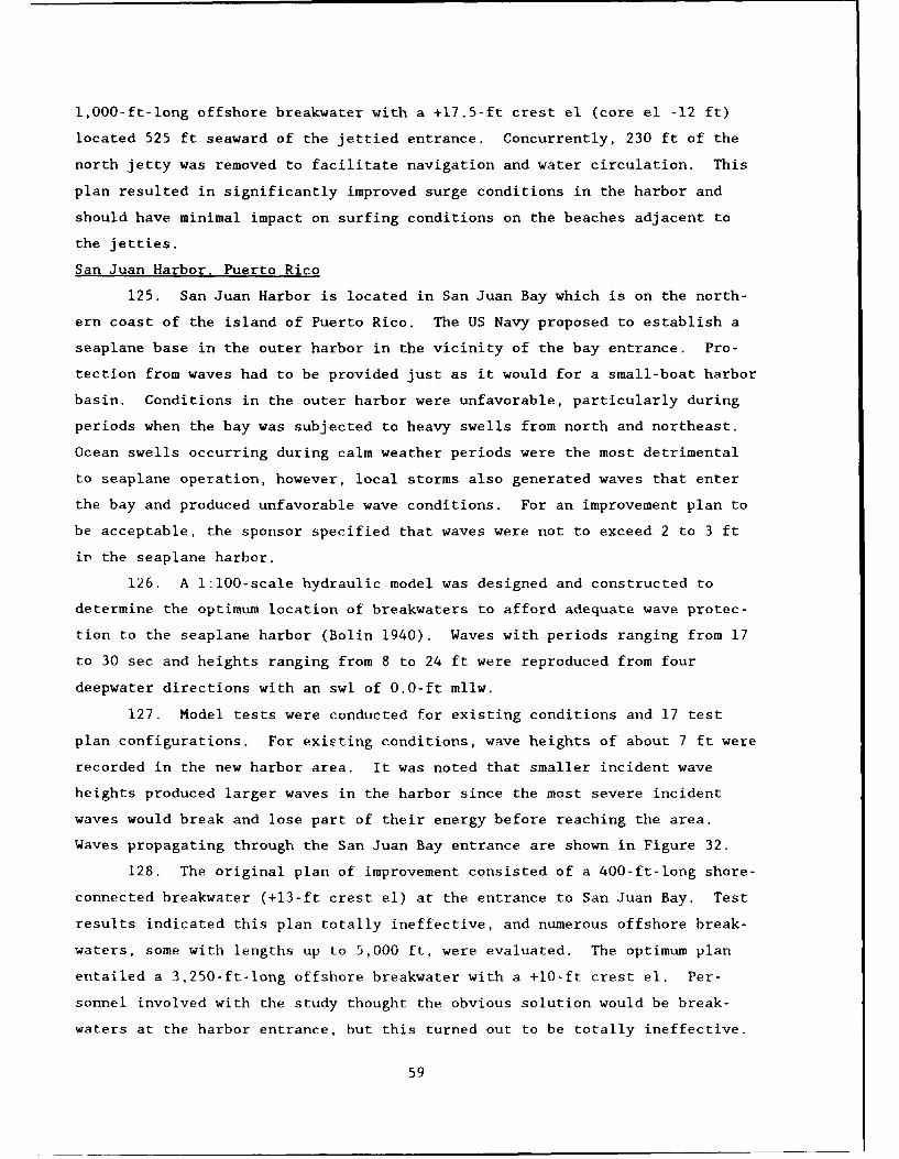
1,000-ft-long offshore breakwater with a +17.5-ft crest el (core el -12 ft)
located 525 ft seaward of the jettied entrance. Concurrently, 230 ft of the
north jetty was removed to facilitate navigation and water circulation. This
plan resulted in significantly improved surge conditions in the harbor and
should have minimal impact on surfing conditions on the beaches adjacent to
the jetties.
San Juan Harbor, Puerto Rico
125. San Juan Harbor is located in San Juan Bay which is on the north-
ern coast of the island of Puerto Rico. The US Navy proposed to establish a
seaplane base in the outer harbor in the vicinity of the bay entrance. Pro-
tection from waves had to be provided just as it would for a small-boat harbor
basin. Conditions in the outer harbor were unfavorable, particularly during
periods when the bay was subjected to heavy swells from north and northeast.
Ocean swells occurring during calm weather periods were the most detrimental
to seaplane operation, however, local storms also generated waves that enter
the bay and produced unfavorable wave conditions. For an improvement plan to
be acceptable, the sponsor specified that waves were not to exceed 2 to 3 ft
in the seaplane harbor.
126. A 1:100-scale hydraulic model was designed and constructed to
determine the optimum location of breakwaters to afford adequate wave protec-
tion to the seaplane harbor (Bolin 1940). Waves with periods ranging from 17
to 30 sec and heights ranging from 8 to 24 ft were reproduced from four
deepwater directions with an swl of 0.0-ft mllw.
127. Model tests were conducted for existing conditions and 17 test
plan configurations. For existing conditions, wave heights of about 7 ft were
recorded in the new harbor area. It was noted that smaller incident wave
heights produced larger waves in the harbor since the most severe incident
waves would break and lose part of their energy before reaching the area.
Waves propagating through the San Juan Bay entrance are shown in Figure 32.
128. The original plan of improvement consisted of a 400-ft-long shore-
connected breakwater (+13-ft crest el) at the entrance to San Juan Bay. Test
results indicated this plan totally ineffective, and numerous offshore break-
waters, some with lengths up to 5,000 ft, were evaluated. The optimum plan
entailed a 3,250-ft-long offshore breakwater with a +10-ft crest el. Per-
sonnel involved with the study thought the obvious solution would be break-
waters at the harbor entrance, but this turned out to be totally ineffective.
59
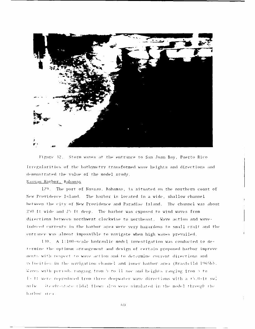
Fi gure 32 . Storm waves at the entrance to San Juan Bay, Puerto Rico
Irrergularit ies of the bathiynietry transformied wave heights and directions and
(lemon1s tra lted thle vI-il e of the model study.
Nassaui Harbor, Bahamas
129. The port of Nassau, Bahamas, is situated on the northern coast of
New Providence Island. The harbor is located in a wide , shallow channel
be tweeni the c~i tv of New Prov idenc e and Paradise Island . The channel was about
2WS ft wide and 2) ft deep . The harbor was expos-d to wind waves from
directions between northwest clockwise to northeast. Wave action and wave-
tindlict-e cuirrents inl the harbor area were very hazardous to small c raft and the
enýlt ranTCe Was almos,ýt impossible to navigate when high waves prevailed.
I M(). A 1 1(00)-scale hvdraul ic model invest igat ion was conducted to de -
t-in i ne the opt inimu airranj.-ement and de sign o t ce r ta in proposed harbor improve -
Intlint; With rteswpc t o walve aicttion anld to detr~imine (litrenit dlirect ions'- anld
VtIc~it ilil i tiek na.vi gat ionl eharifnet 1 and inner-l harbi-or area ( Bralsfe iid Thb
V~vW;it Ii pci 0±;oý rang1ýing t reml ) to !I sec and lie igIit " agn tron] t (I
fw"-We Irt'I) reit eIc ' t roi l tl ieeý (lee)w, t- ter wave d irec t ikoil', with aI+' ±.0)-ft sw I
Ii i lW, ti t idail t ]ew!. il';o WtrIc iml a~t id inl thle ilmodel ti brooch' ttie-
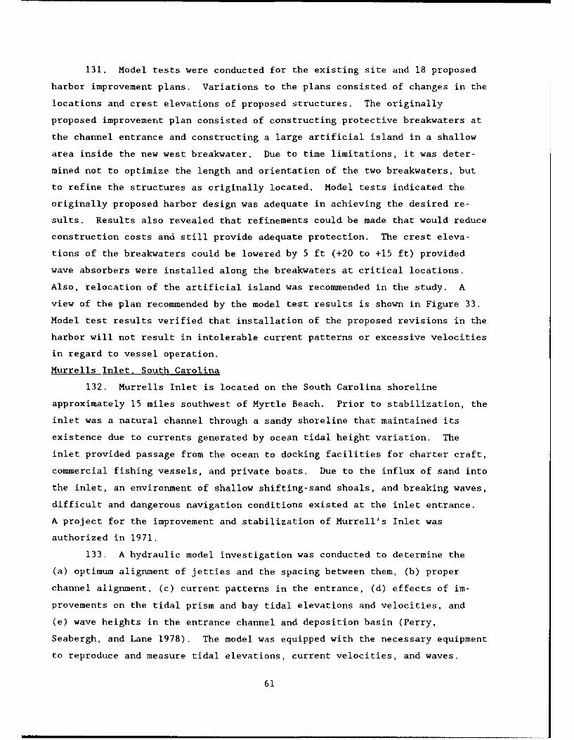
131. Model tests were conducted for the existing site and 18 proposed
harbor improvement plans. Variations to the plans consisted of changes in the
locations and crest elevations of proposed structures. The originally
proposed improvement plan consisted of constructing protective breakwaters at
the channel entrance and constructing a large artificial island in a shallow
area inside the new west breakwater. Due to time limitations, it was deter-
mined not to optimize the length and orientation of the two breakwaters, but
to refine the structures as originally located. Model tests indicated the
originally proposed harbor design was adequate in achieving the desired re-
sults. Results also revealed that refinements could be made that would reduce
construction costs and still provide adequate protection. The crest eleva-
tions of the breakwaters could be lowered by 5 ft (+20 to +15 ft) provided
wave absorbers were installed along the breakwaters at critical locations.
Also, relocation of the artificial island was recommended in the study. A
view of the plan recommended by the model test results is shown in Figure 33.
Model test results verified that installation of the proposed revisions in the
harbor will not result in intolerable current patterns or excessive velocities
in regard to vessel operation.
Murrells Inlet. South Carolina
132. Murrells Inlet is located on the South Carolina shoreline
approximately 15 miles southwest of Myrtle Beach. Prior to stabilization, the
inlet was a natural channel through a sandy shoreline that maintained its
existence due to currents generated by ocean tidal height variation. The
inlet provided passage from the ocean to docking facilities for charter craft,
commercial fishing vessels, and private boats. Due to the influx of sand into
the inlet, an environment of shallow shifting-sand shoals, and breaking waves,
difficult and dangerous navigation conditions existed at the inlet entrance.
A project for the improvement and stabilization of Murrell's Inlet was
authorized in 1971.
133. A hydraulic model investigation was conducted to determine the
(a) optimum alignment of jetties and the spacing between them, (b) proper
channel alignment, (c) current patterns in the entrance, (d) effects of im-
provements on the tidal prism and bay tidal elevations and velocities, and
(e) wave heights in the entrance channel and deposition basin (Perry,
Seabergh, and Lane 1978). The model was equipped with the necessary equipment
to reproduce and measure tidal elevations, current velocities, and waves.
61
Figure 33. Recommended plan of improvement for Nassau Harbor,Bahamas
Prior to testing of improvements, the model tidal elevations and velocities
were verified based on prototype data previously obtained.
134. The originally proposed improvement plan consisted of a
2,800-ft-long north jetty with a 1,300-ft low weir section, a 2,300-ft-long
south jetty, two sand dikes, an entrance channel, an inner channel, and a
deposition basin. Numerous modifications were made in the model and an opti-
mum plan was developed that provided a stable entrance channel while minimiz-
ing other undesirable effects. The optimum plan included a 3,455-ft-long
north jetty with a 1,330-ft low weir section, a 3,330-ft-long south jetty, two
sand dikes, an entrance channel, an inner channel, a deposition basin, and a
training dike. Figure 34 is a photo of the plan showing surface current pat-
terns. Test results revealed that the recommended plan would have no signifi-
cant impacts on tidal conditions and entrance velocity conditions, would be
conducive to a self-maintaining channel, and would have no impact on the tidal
prism.
62

Figure 34. Typical surface current patterns foroptimum plan developed in the Murrells Inlet,
South Carolina, hydraulic model
Little River Inlet, South Carolina
135. Little River Inlet was an unimproved tidal inlet along the state
border of North and South Carolina. The inlet provided passage to the ocean
from a sheltered bay for charter and commercial fishing boats and private
recreational vessels. It also provided access to the Atlantic Intracoastal
Waterway from the ocean. Dynamic charges in the position of the main ebb
channel and inlet shoals were historically experienced within the inlet open-
ing. The narrow navigable channel and shallow-bar regions resulted in
63
difficult and dangerous navigation conditions. Improvements for the inlet
were authorized in 1972.
136. A hydraulic model investigation was conducted to determine the
(a) optimum alignment of jetties and the spacing between them, (b) minimum
length of jetties required, (c) proper channel alignment, (d) characteristics
of the channel with respect to the influx of sediment at the entrance,
(e) effectiveness of weirs on the jetties to pass longshore drift into the
sedimentation basins, (f) effects on tidal prisms and bay tides, (g) effects
on bay salinities, (h) wave heights in the entrance channel and deposition
basin, and (i) location of sediment basins (Seabergh and Lane 1977). The
model was equipped with all necessary appurtenances to reproduce and measure
tidal elevations, current velocities, waves, freshwater inflows, sediments
used in shoaling tests, and salinity. Prior to testing of improvement plans,
the model was verified based on prototype data obtained.
137. The originally proposed improvement plan consisted of two jetties,
sand dikes, a 300-ft-wide entrance channel through the offshore bar, and a
90-ft-wide inner channel. Modifications were made to the originally proposed
configuration which included shortening of the jetty system and the instal-
lation of weirs on each jetty to trap longshore drift. Armoring various areas
of the system also would prevent erosion at specific locations determined in
the model study. Tracer tests indicated that the location, orientation, and
elevations of the weirs and sediment basins were effective in permitting long-
shore sediment transport to pass over the weirs into the basin for the optimum
plan, and the spacing between jetties was adequate to pass tidal flow without
excessively high or undesirably low velocities. The improvement plan also
resulted in no significant change to the salinity regimen of the bay. The
optimum improvement plan is shown in Figure 35.
Masonboro Inlet, North Carolina
138. Masonboro Inlet is a natural inlet through the coastal beach of
North Carolina located 8 miles northeast of Wilmington, NC. The inlet provid-
ed vessel passage from the ocean to the Atlantic Intracoastal Waterway and to
various private and commercial docking facilities. Construction of a
3,679-ft-long jetty on the north side of the inlet with a 1,100-ft-long weir
at a 0-ft el at its shoreward end and a deposition basin was completed in
1965. The plan functioned well until the entrance channel migrated toward the
jetty and cut through the deposition basin, jeopardizing the structural
64
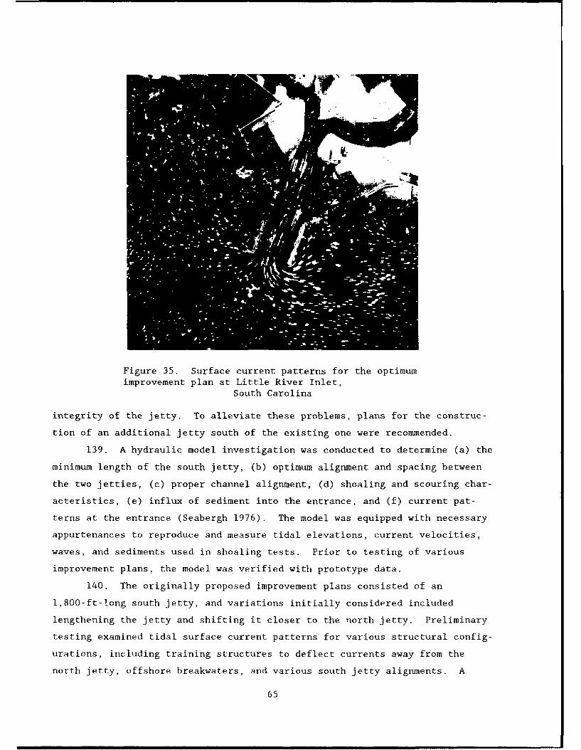
Figure 35. Surface current patterns for the optimumimprovement plan at Little River Inlet,
South Carolina
integrity of the jetty. To alleviate these problems, plans for the construc-
tion of an additional jetty south of the existing one were recommended.
139. A hydraulic model investigation was conducted to determine (a) the
minimum length of the south jetty, (b) optimum alignment and spacing between
the two jetties, (c) proper channel alignment, (d) shoaling and scouring char-
acteristics, (e) influx of sediment into the entrance, and (f) current pat-
terns at the entrance (Seabergh 1976). The model was equipped with necessary
appurtenances to reproduce and measure tidal elevations, current velocities,
waves, and sediments used in shoaling tests. Prior to testing of various
improvement plans, the model was verified with prototype data.
140. The originally proposed improvement plans consisted of an
1,800-ft-long south jetty, and variations initially considered included
lengthening the jetty and shifting it closer to the north jetty. Preliminary
testing examined tidal surface current patterns for various structural config-
urations, including training structures to deflect currents away from the
north jetty, offshore breakwaters, and various south jetty alignments. A
65

3,400-ft-long south jetty was determined to be the best plan tested. It was
noted that the south jetty, about the same length of the north jetty,
prevented a swing of flood currents toward the north structure, and flood
flows showed good alignment at the entrance and through the region between the
jetties (Figure 36), with the flow lines concentrated in the center of the
jetties. With this plan in place, there should be no significant change to
the tidal prism of the inlet, and bay elevations and velocities should remain
very similar to existing conditions for the optimum plan. Tests indicated,
also, that an increase in currents over the weir portion of the north jetty
should occur, resulting in greater littoral movement to the deposition basin.
Figure 36. Optimum jetty configuration developed for Masonboro Inlet,North Carolina
Oregon Inlet, North Carolina
141. Oregon Inlet, the northernmost inlet through North Carolina's
barrier islands, is a natural channel passing tidal flows between the Atlantic
Ocean and extensive open bay sounds. Typical of many natural inlets, naviga-
tion through the inlet can be dangerous due to shallow shifting sand shoals,
as evidenced by numerous occurrences of damage sustained by fishing vessels.
The necessity of co.tinued maintenance dredping and the exposure of commercial
and private craft to shoaling and breaking waves indicated that inlet
stabilization by jetties was desirable.
142. A hydraulic model investigation was -"nducted to determine (a) op-
timum jetty alignment and spacing between jetties, (b) :,inimum length of the
66
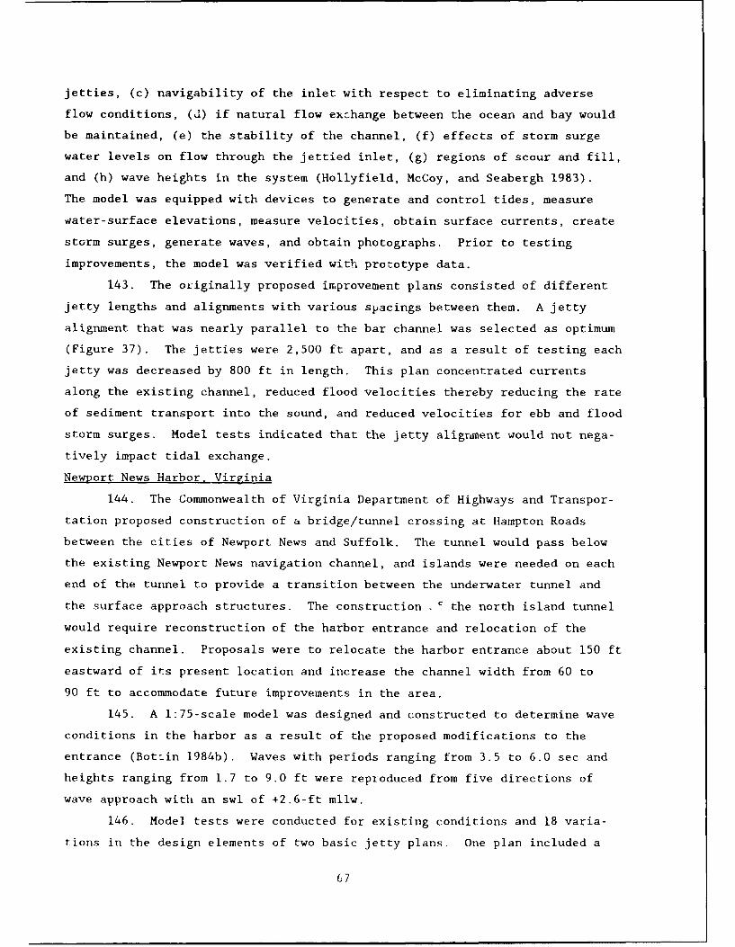
jetties, (c) navigability of the inlet with respect to eliminating adverse
flow conditions, (d) if natural flow exzhange between the ocean and bay would
be maintained, (e) the stability of the channel, (f) effects of storm surge
water levels on flow through the jettied inlet, (g) regions of scour and fill,
and (h) wave heights in the system (Hollyfield, McCoy, and Seabergh 1983).
The model was equipped with devices to generate and control tides, measure
water-surface elevations, measure velocities, obtain surface currents, create
storm surges, generate waves, and obtain photographs. Prior to testing
improvements, the model was verified with prototype data.
143. The originally proposed improvement plans consisted of different
jetty lengths and alignments with various spacings between them. A jetty
alignment that was nearly parallel to the bar channel was selected as optimum
(Figure 37). The jetties were 2,500 ft apart, and as a result of testing each
jetty was decreased by 800 ft in length. This plan concentrated currents
along the existing channel, reduced flood velocities thereby reducing the rate
of sediment transport into the sound, and reduced velocities for ebb and flood
storm surges. Model tests indicated that the jetty alignment would not nega-
tively impact tidal exchange.
Newport News Harbor. Virginia
144. The Commonwealth of Virginia Department of Highways and Transpor-
tation proposed construction of a bridge/tunnel crossing at Hampton Roads
between the cities of Newport News and Suffolk. The tunnel would pass below
the existing Newport News navigation channel, and islands were needed on each
end of the tunnel to provide a transition between the underwater tunnel and
the surface approach structures. The construction ' the north island tunnel
would require reconstruction of the harbor entrance and relocation of the
existing channel. Proposals were to relocate the harbor entrance about 150 ft
eastward of its present location and increase the channel width from 60 to
90 ft to accommodate future improvements in the area.
145. A 1:75-scale model was designed and constructed to determine wave
conditions in the harbor as a result of the proposed modifications to the
entrance (Bot.in 1984b). Waves with periods ranging from 3.5 to 6.0 sec and
heights ranging from 1.7 to 9.0 ft were reproduced from five directions of
wave approach with an swl of +2.6-ft mllw.
146. Model tests were conducted for existing conditions and 18 varia-
tions in the design elements of two basic jetty plans. One plan included a
67

Figure 37. Jetties aligned parallel to the bar channel wereoptimum for Oregon Inlet, North Carolina
rubble-mound jetty and one entailed a concrete pile jetty, and both were con-
structed in conjunction with the north tunnel island bayward of the existing
entrance. Storm waves from various directions produced relatively calm wave
conditions in the existing harbor with wave heights in excess of 1.0 ft only
for the most severe storm waves (50-year recurrence).
147. The first harbor configuration entailed a 1,225-ft-long rubble-
mound jetty with a +12.3-ft crest el. Tests indicated the structure could be
reduced in length by 300 ft and the crest elevation could be reduced by 3 ft
in height (Figure 38) with no adverse effects on wave conditions in the
harbor. The second harbor configuration consisted of a 2,710-ft-long concrete
cylinder-pile (66-in.-diam) breakwater with the piles spac2d 6 in. apart and
the openings sealed with timber from the crest to a -0.7-ft el. This plan
resulted in excessive wave heights in the existing harbor. Test results
68
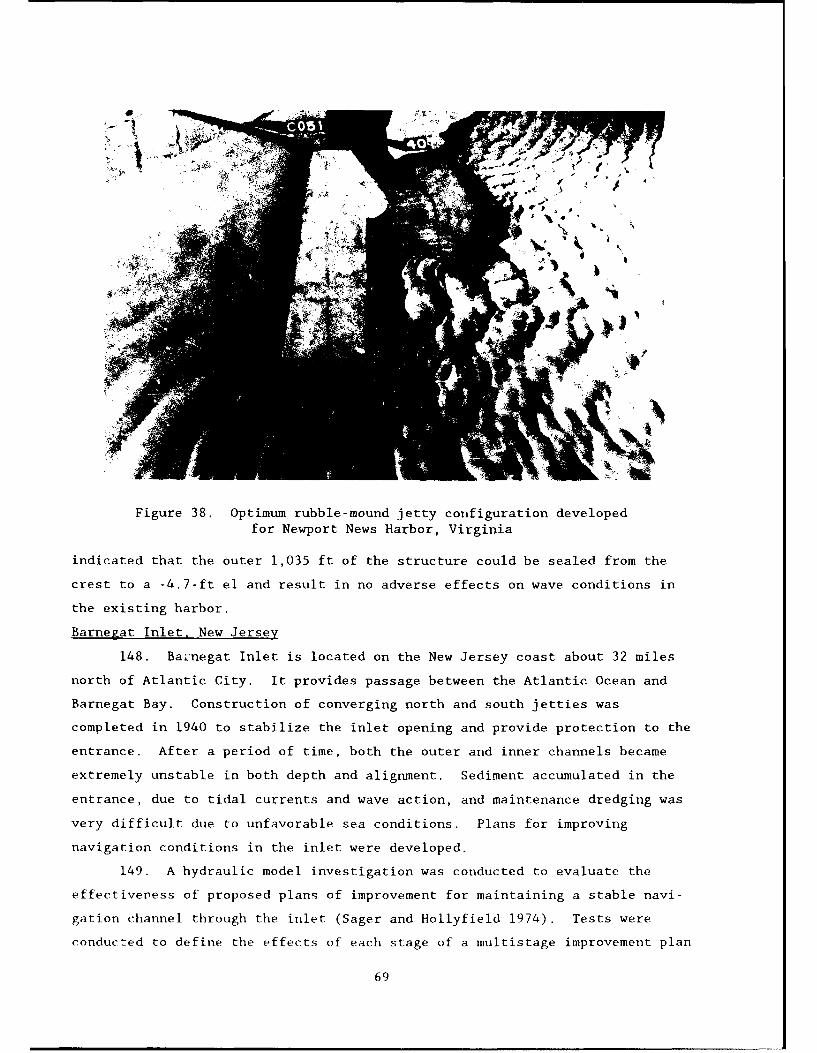
Figure 38. Optimum rubble-mound jetty configuration developedfor Newport News Harbor, Virginia
indicated that the outer 1,035 ft of the structure could be sealed from the
crest to a -4.7-ft el and result in no adverse effects on wave conditions in
the existing harbor.
Barnegat Inlet, New Jersey
148. Ba;negat Inlet is located on the New Jersey coast about 32 miles
north of Atlantic City. It provides passage between the Atlantic Ocean and
Barnegat Bay. Construction of converging north and south jetties was
completed in 1940 to stabilize the inlet opening and provide protection to the
entrance. After a period of time, both the outer and inner channels became
extremely unstable in both depth and alignment. Sediment accumulated in the
entrance, due to tidal currents and wave action, and maintenance dredging was
very difficult due to unfavorable sea conditions. Plans for improving
navigation conditions in the inlet were developed.
149. A hydraulic model investigation was conducted to evaluate the
effectiveness of proposed plans of improvement for maintaining a stable navi-
gation channel through the inlet (Sager and Hollyfield 1974). Tests were
conducted to define the effects of each stage of a multistage improvement plan
69

on the hydraulic characteristics of the inlet. Prior to testing of various
plans of improvement, comprehensive tests were conducted to verify the model
with prototype data. The model was equipped with necessary appurtenances for
generating tides and waves and for measuring tidal heights, velocities, and
bottom e:"yations. In addition, photographic techniques were used to
delineate surface current patterns.
150. The improvement plan developed for Barnegat Inlet entailed con-
struction to be accomplished in seven stages. Model tests, however, indicated
that two additional construction stages should be accomplished to even the
distribution of flow and prevent crosscurrents that existed between the jet-
ties. Analysis of model test results indicated that construction of a new
south jetty was more effective for maintenance of a suitable navigation chan-
nel than raising the north jetty, and priority of construction should be given
to the south jetty (Figure 39). In addition, it was determined that the
parallel jetties would probably eliminate three of the construction stages
bayward of the entrance. The channel dredged initially between the jetties
was inadequate to preserve the tidal discharge and concentrate the flow along
the alignment of the channel. The model study recommended new location,
alignment, and dimensions of the entrance channel.
Shrewsbury Inlet, New York
151. Shrewsbury Inlet is located in New York Harbor south of Sandy Hook
Bay. A small-boat channel was proposed across the base of Sandy Hook
Peninsula for recreational boating and commercial navigation.
152. A 1:100-scale hydraulic model investigation was conducted to de-
termine (a) the optimum location and length of the protection jetties,
(b) transmission of wave energy through the inlet, and (c) detailed current
velocities in critical locations for various flood and ebb discharges through
the proposed small-boat inlet (McNair and Hill 1972). Waves with periods
ranging from 6.6 to 11.2 sec and heights ranging from 2.7 to 10.5 ft were
reproduced from one direction for swl's of 0.0-, +2.3-, and/or +3.9-ft mean
low water (mlw). For some tests, flood and ebb tidal flows were reproduced
through the entrance.
153. Seven improvement plans were tested which involved different chan-
nel alignments and depths and/or various lengths and locations of the jetties.
The model revealed that 800-ft-long jetties spaced 508 ft apart with a channel
extending straight through the jetties and then turning southwesterly to an
70
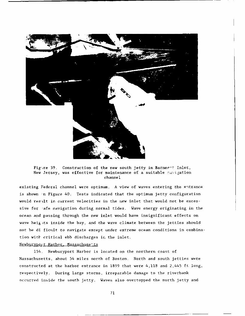
Fig'ure 39. Construction of the new south jetty in Barne,:" Inlet,New Jersey, was effective for maintenance of a suitable navigation
channel
existing Federal channel were optimum. A view of waves entering the entrance
is shown n Figure 40. Tests indicated that the optimum jetty configuration
would res'ilt in current velocities in the new inlet that would not be exces-
sive for 7afe navigation during normal tides. Wave energy originating in the
ocean and passing through the new inlet would have insignificant effects on
wave heig its inside the bay, and the wave climate between the jetties should
not be di ficiilt to navigate except under extreme ocean conditions in combina-
tion witi' critical ebb discharges in the inlet.
Newburypoit Harbor, Massachuse'ts
154. Newburyport Harbor is located on the northern coast of
Massachusetts, about 54 miles north of Boston. North and south jetties were
constructed at the harbor entrance in 1899 that were 4,118 and 2,445 ft long,
respectively. During large storms, irreparable damage to the riverbank
occurred inside the south jetty. Waves also overtopped the north jetty and
71

ShA_
A -A
9-&
Figure 40. Jetty configuration tested in the Shrewsbury Inlet,New York, model
eroded sand in front of a Coast Guard station located there. A revetment was
ins~talled in front o~f the Coast Guard station and the erosion problem was
subsequently tranisferred upriver.
155. A 1:75-scale hydraulic model study was conducted to stuidy wave,
shoalinig, and erosion problems at the site and determine the effects of vari-
ous improvement plans (Curren and Chathanm 1979) . Waves with periods ranging
from 7 to 15) sec and he ighits ranging from 4 to 18 tt were reproduced from
three de-pwater direct ions wi th SWl 's Of 0. 0- , 4-2 . 9- , and/or A-5.3 -ftt mean sealevel (w.s 1) .Maximnumi flood and ebb tidal dischiarges also were reproduced
72

through the entrance in the model. These tidal discharges were combined with
a typical freshwater discharge (8,200 cfs) and the resultant combined
discharges were reproduced in the model.
156. Model tests were conducted for existing conditions and 13 test
plan configurations which consisted of changes in the length and crest eleva-
tion of the north breakwater and the addition of groins at various locations.
Test results for existing conditions revealed rough and turbulent wave condi-
tions in the entrance channel due to waves breaking on a shoal across the
entrance, waves diffracting around the jetty heads, and waves overtopping the
north jetty. Tracer tests indicated that the model accurately reproduced the
general sediment patterns observed in the prototype (as evidenced by visual
observations and aerial photographs).
157. Initially, improvement plans were tested that entailed raising the
crest elevation of the north breakwater from +8.3 ft (existing elevation) to
elevations ranging from +11 to +17 ft. North breakwater extensions to
1,000 ft in length with +8.3 and +11 ft crest el then were tested. In addi-
tion, north and south groins were installed inside the entrance with a +10-ft
el. Model tests revealed that an 850-ft-long south groin in conjunction with
raising the existing north jetty to an +11-ft el (Figure 41) would provide
adequate erosion protection while improving entrance wave conditions. This
plan was considered optimum with regard to the protection provided and con-
struction costs.
Wells Harbor, Maine
158. Wells Harbor, Maine, is a small inlet located at the mouth of the
Webhannet River about 20 miles northeast of Portsmouth Harbor, Maine. It is
primarily a summer resort area for small pleasure boats. Construction of an
840-ft-long north jetty and a 940-ft-long south jetty was completed at the
site in 1962. Excessive shoaling occurred in the harbor entrance after jetty
construction, and in 1967 the north and south jetties were extended by 1,225
and 1,300 ft, respectively. These jetty extensions were unsuccessful in elim-
inating shoaling problems. The entrance channel did not maintain a self-
scouring depth and frequent dredging was required. In addition, little wave
protection was afforded to small boats navigating the channel during periods
of storm wave activity.
159. A 1:50-scale hydraulic model was designed and constructed to study
wave and current conditions in the Wells H.irbor entrance channel both with and
73
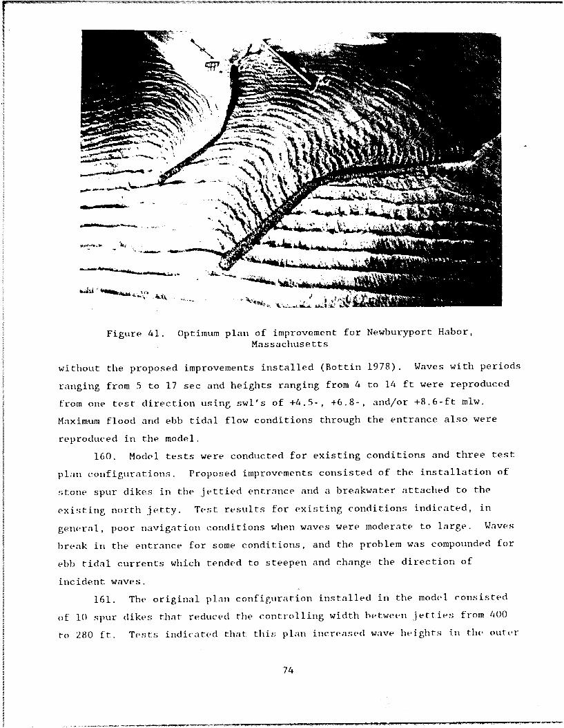
JI le
Figure 41. Optimum plan of improvement for Newburyport Habor,Massachusetts
without the proposed improvements installed (Bottin 1978). Waves with periods
ranging from 5 to 17 sec and heights ranging from 4 to 14 ft were reproduced
from one test direction using swi's of +4.5-, +6.8-, and/or +8.6-ft miw.
Maximum flood and ebb tidal flow conditions through the entrance also were
reproduced in the model.
160. Model tests were conducted for existing conditions and three test
plan configurations. Proposed improvements consisted of the installation of
stone spur dikes in the jettied entrance and a breakwater attached to the
existing north jetty. Test results for existing conditions indicated, in
general, poor navigation conditions when waves were moderate to large. Waves
break in the entrance for some conditions, and the problem was compounded for
ebb tidal currents which tended to steepen and change the direction of
incident waves.
161. The original plan configuration installed in the model consisted
of 10 spur (likes that reduced the controlling width between jetties from 400
to 280 ft. Tests indicated that this plan increased wave heights in the outer
74
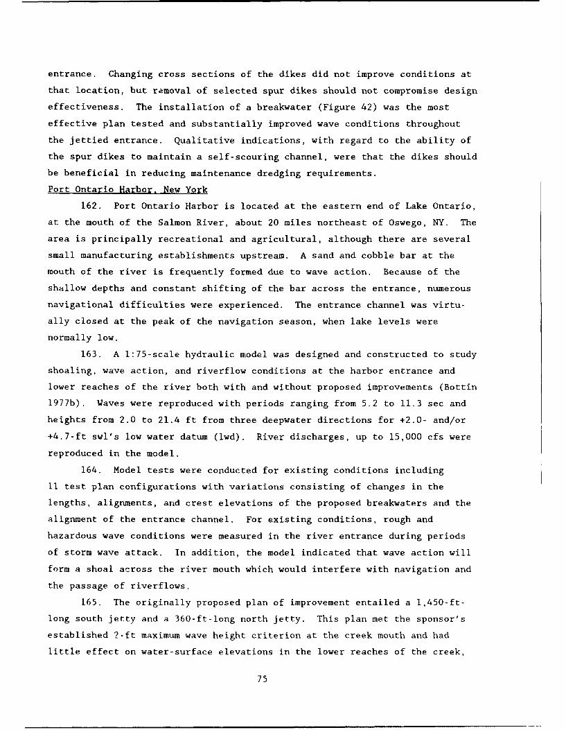
entrance. Changing cross sections of the dikes did not improve conditions at
that location, but removal of selected spur dikes should not compromise design
effectiveness. The installation of a breakwater (Figure 42) was the most
effective plan tested and substantially improved wave conditions throughout
the jettied entrance. Qualitative indications, with regard to the ability of
the spur dikes to maintain a self-scouring channel, were that the dikes should
be beneficial in reducing maintenance dredging requirements.
Port Ontario Harbor, New York
162. Port Ontario Harbor is located at the eastern end of Lake Ontario,
at the mouth of the Salmon River, about 20 miles northeast of Oswego, NY. The
area is principally recreational and agricultural, although there are several
small manufacturing establishments upstream. A sand and cobble bar at the
mouth of the river is frequently formed due to wave action. Because of the
shallow depths and constant shifting of the bar across the entrance, numerous
navigational difficulties were experienced. The entrance channel was virtu-
ally closed at the peak of the navigation season, when lake levels were
normally low.
163. A 1:75-scale hydraulic model was designed and constructed to study
shoaling, wave action, and riverflow conditions at the harbor entrance and
lower reaches of the river both with and without proposed improvements (Bottin
1977b). Waves were reproduced with periods ranging from 5.2 to 11.3 sec and
heights from 2.0 to 21.4 ft from three deepwater directions for +2.0- and/or
+4.7-ft swl's low water datum (lwd). River discharges, up to 15,000 cfs were
reproduced in the model.
164. Model tests were conducted for existing conditions including
11 test plan configurations with variations consisting of changes in the
lengths, alignments, and crest elevations of the proposed breakwaters and the
alignment of the entrance channel. For existing conditions, rough and
hazardous wave conditions were measured in the river entrance during periods
of storm wave attack. In addition, the model indicated that wave action will
form a shoal across the river mouth which would interfere with navigation and
the passage of riverflows.
165. The originally proposed plan of improvement entailed a 1,450-ft-
long south jetty and a 360-ft-long north jetty. This plan met the sponsor's
established 2-ft maximum wave height criterion at the creek mouth and had
little effect on water-surface elevations in the lower reaches of the creek,
75

nIlodc' 1
F' un 4 Mstefec ly pnntetel n he i- i HrbrMane

but it was not optimum considering prevention of shoaling. After additional
tests, it was determined that a 460-ft-long north jetty and a 1,450-ft-long
south structure were optimum with respect to shoaling protection. Model test
results indicated that the south breakwater could be reduced in crest eleva-
tion by 2 ft (+12 to +10 ft) and not increase wave heights between the
structures. The optimum improvement plan tested for Port Ontario Harbor is
shown in Figure 43.
j•d
Figure 43. Optimum improvement plan for Port OntarioHarbor, New York
Oswego Harbor, New York
166. Oswego Harbor is located on the southern shore of Lake Ontario,
about 15 miles from its easterly end, at the mouth of the Oswego River. The
harbor was afforded some protection from storm waves by converging rubble-
mound breakwaters which form a 650-ft-wide navigation opening. Storms, how-
ever, from north-northwest to north-northeast propagated through the entrance
and caused considerable damage to harbor facilities. Plans were developed to
protect the navigation opening and improve wave conditions in the harbor.
167. A 1:100-scale hydraulic model study was conducted to determine if
a proposed breakwater was adequate to protect the harbor from storm waves, and
if not, to devise a plan which would afford sufficient protection (Fortson
77

et al. 1949). Waves with periods ranging from 5.2 to 8.2 sec and heights
ranging from 7 to 18 ft were reproduced from four deepwater directions of
approach with +3.5-ft low water datum (lwd).
168. Tests were conducted for existing conditions and eight breakwater
improvement plans. Existing conditions indicated that the most critical
direction of wave approach, with regard to wave action in the harbor, was from
north (Figure 44). Wave heights in excess of 10 ft were measured in the
harbor. The originally proposed improvement plan consisted of removal of
1,030 ft of the shoreward end of the east breakwater with a 4,900-ft-long
extension of this structure extending easterly to shore. A 1,000-ft-long
detached breakwater was included lakeward of the entrance. Test results indi-
cated that this plan would not afford adequate wave protection. The detached
breakwater reflected westerly waves into the harbor. Although numerous plans
were tested, the optimum breakwater alignment with respect to wave protection
and cost entailed moving the detached breakwater 400 ft shoreward and decreas-
ing its length by 350 ft. A spending beach in the corner of one of the basins
also was necessary. Wave he, 6hts were reduced to 2 ft or less in the harbor
for this plan.
Hamlin Beach Harbor. New York
169. Hamlin Beach Harbor was proposed for construction on the south
shore of Lake Ontario, in Hamlin Beach State Park, which is about 17 miles
northwest of Rochester, NY. There was no development at the site, and pro-
posed improvements consisted of breakwaters to protect the harbor entrance, an
entrance channel, and an interior channel adjacent to a berthing area. Storm
waves in this area of the lake ranged up to 10 ft in height and made naviga-
tion difficult and dangerous for small craft near shore and caused serious
damage to moored small boats.
170. A 1:64-scale hydraulic model was designed and constructed to de-
termine the optimum length of the protective structures proposed at the harbor
entrance with respect to economics and wave heights in the basin (Brasfeild
1973). Waves were reproduced from three directions of approach that ranged
from 7 to 8 sec in period and 7.6 to 10.2 ft in height for a +5.0-ft swl. For
a plan to be accepta '_e, the sponsor specified that wave heights were not to
exceed 2.5 ft and 0.5 ft in the entrance and berthing area, respectively.
171. The originally proposed improvements consisted of the installation
of a 950-ft-long west breakwater and a 270-ft-long east breakwater. Test
78

Figure 44. View of wave action from north entering the existingOswego Harbor,New York
results revealed that wave heights were well within the established criterion,
and that 100 ft of the lakeward end of west breakwater could be removed
(Figure 45) and still provide adequate protection to the entrance and harbor.
Test results also revealed that an additional 100-ft reduction in length of
the west breakwater would not seriously impair the protection desired for the
harbor. Wave height criteria should he exceeded slightly during storm wave
attacks from the easterly directions.
Olcott Harbor, New York
172. Olcott Harbor, New York, is located on the southern shore of Lake
Ontario at the mouth of Eighteenmile Creek, situated about 18 miles east of
the mouth of the Niagara River. Concrete-capped, steel sheet pile, vertical,
parallel jetties are located 200 ft apart at the creek mouth. The harbor was
fully developed with boat docks and facilities on both banks of the creek and
had a mooring capacity of 134 vessels. Waves in the entrance were extremely
hazardous during storms when waves reflected off and overtopped the vertical
jetties in the entrance. In addition, waves entering the harbor between the
jetties broke vessels loose from their moorings resulting in vessel and
79
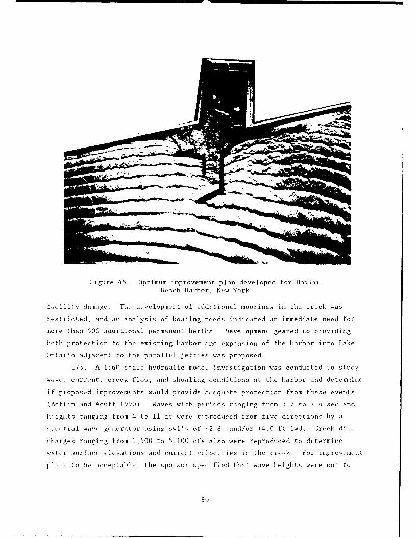
Figure 45. Optimum improvement plan developed for HanlinBeach Harbor, New York
facility damage. The development of additional moorings in the creek was
restricted, and an analysis of boating needs indicated an immediate need for
more than 500 additional permanent berths. Development geared to providing
both protection to the existing harbor and expansion of the harbor into Lake
Ontario adjacent to the parallel jetties was proposed.
173. A 1:60-scale hydraulic model investigation was conducted to study
wave, current, creek flow, and shoaling conditions at the harbor and determine
if proposed improvements would provide adequate protection from these events
(Bottin and Acuff 1990). Waves with periods ranging from 5.7 to 7.4 sec and
V•igi~ts ranging from 4 to 11 ft were reproduced from five directions by a
spectral wave generator using swl's of +2.8- and/or +4.0-ft lwd. Creek dis-
charges ranging from 1,500 to 5,100 cfs also were reproduced to determine
,%-iter surface elevations and current velocities in the c-,(ok. For improvement
pl:ins to be acceptable, the sponsor specified that wave heights were not to
80

exceed 3 ft in the proposed entrance or 1 ft in the proposed mooring areas for
wave conditionr occurring during boating season.
174. Model tests were conducted for the existing harbor configuration
and for 23 test plan variations of two basic harbor configurations. One con-
figuration provided a mooring area to the east of the existing entrance, and
one conriguration provided mooring areas on both the east and west sides of
the existing entrance. Test results for existing conditions revealed rough
wave conditions in the entrance with heights up to 6.5 ft. Confused wave
patterns were observed between the jetties due to reflections from the
vertical-wall structures.
175. The first basic harbor configuration consisted of a 1,110-ft-long
west dogleg breakwater, a 1,650-ft-long detached east breakwater, a 340-ft-
long east spur breakwater, and channel dredging. A mooring area was provided
on the east side of the existing entrance. The second basic harbor configura-
tion provided for mooring areas on both the east and west sides of the exist-
ing entrance. It consisted of detached 1,570-ft-long west dogleg breakwater,
a 270-ft-long west spur breakwater, a 1,650-ft-long detached east breakwater,
and a 340-ft-long east spur breakwater.
176. Test results for both the first and second harbor configurations
revealed that wave heights were well within the established criteria for both
plans. Model tests indicated that the crest elevations of both breakwaters
could be reduced in height and that the east breakwater could be reduced by
125 ft in length for both configurations. In addition, 350 ft could be re-
moved from the west breakwater of the first harbor configuration and 50 ft
could be removed from the west breakwater of the second harbor configuration
and the established 1-ft maximum wave height criterion in the harbor could be
met. Tests also revealed that the construction of either harbor plan would
have minimal impact on water surface elevations and creek current velocities
in the lower reaches of Eighteenmile Creek. A view of the second basic harbor
configuration with optimum improvements is shown in Figure 46. The openings
between tt,- attached and detached breakwaters will provide wave-induced cur-
rent flow through the harbor, however, the opening between the attached and
detached west breakwaters of the second basic harbor configuration may result
in minor shoaling in the mooring area in the western portion of the harbor for
waves from westerly directions. The installation of a sill between the
81

Figure 46. Optimumi plan of improvement for the second basic harbhorconfiguration tested in the Olcott Harbor, New York, model
struict-uref;, an extension of the shore-connected breakwater, or a. spur onl the
!;Iiorecouniee ted structure should alleviate this shoal ing.
1/7. Additional tests were conducted for the second basic harbor conl-
f~iguriationl to determine the effects of the proposed improvements onl creek
Cemperatures and currents at. Eighteenminle Creek as they entered the Lake( Bot tin 1990) . Tests were conduc ted to verify the performance of the miode I
W[IIh pototype- dataZ Ohtajinedl [or existing conditions. A reservoir ot heated
wd t(i tWa!; itSd to0 initIroduct, di scharges5 into( the c*ree(k for the spring and tall
!seasons 11!. The discharge water was dyed so that current patterns could hc
t raced . I t was concluded thmat tihe proposed i improve me n ts should have no ad -
ye r!; e impasc t o11 t eimpertatulre var iations1 or the movemenlt of creek Wa ter inito tile
IlikE, an1d :i 1 oim, thle shiore Iinte . S imin i.a r trends wi t Ii rega; rdl to tcipPatulVe var i -
.'itij.ots wee tE measured in the entrVance aind the Lake , anid moveme(nt oft the (creek
1) ummm i litto the Lake and a long_ the' shore I iW tie vrie'd SI i gh t- ly in a 1.00;ja ii:: c
:m1e :thIle en1tranlce but Was]! similar oil aI regicuma 1fi i or the i mp rovememitt
82

Cattaraugus Creek Harbor, New York
178. Cattaraugus Creek enters the lake on the south shore of Lake Erie
about 24 miles southwest of Buffalo, NY. The harbor consisted of the lower
3/4 mile of the creek where over 400 small boats were permanently based. The
economy of the immediate area was primarily recreational. Flooding occurred
almost every year along the lower reaches of the creek primarily due to the
presence of a restrictive sand and gravel bar at the creek mouth. The bar,
formed by littoral drift due to wave action, at times virtually closed the
outlet and caused navigational difficulties because of shallow depths and the
constant shifting of the bar across the entrance. A plan of improvement was
proposed to provide wave protection to the harbor and prevent the formation of
the sand and gravel bar at the creek mouth.
179. A 1:75-scale hydraulic model investigation was conducted to study
shoaling, wave action, and flood and ice flow conditions at the harbor en-
trance and lower reaches of the creek both with and without proposed improve-
ments (Bottin and Chatham 1975). Waves with periods ranging from 6 to 9 sec
and heights ranging from 4 to 14 ft were reproduced from three directions of
approach for swl's of 0.0- and/or +3.0-ft lwd. Creek discharges ranging from
10,000 to 57,900 cfs were reproduced in the model. Crushed coal was used to
simulate sediment in the model and a low-density polyethylene sheet material
was used to simulate ice.
180. Model tests were conducted for existing conditions and nine test
plan configurations. For existing conditions, the model indicated that wave
action would form a shoal across the creek mouth which would seriously inter-
fere with navigation and the passage of flood flows and ice. During periods
when the shoal was absent (washed out by flood flows) wave heights would be
excessive in the creek mouth and lower reaches of the creek. The originally
proposed improvement plan consisted of a navigation opening and entrance chan-
nel (protected from waves by a sheet-pile breakwater) oriented toward the
west. This plan resulted in excessive shoaling of the entrance. Since the
predominant direction of littoral drift at and near the mouth would shoal the
entrance, the breakwater orientation was not considered feasible.
181. Additional testing indicated that a navigation opening oriented
toward the east with rubble-mound breakwaters aggregating 2,450 ft was the
optimum plan (Figure 47). The plan showed no ice jamming tendencies and
should help prevent the formation of windrowed lake ice at the entrance. Wave
83

//
//7
,I I
Figure 47. Optimum breakwater configuration developed in the modelstudy of Cattaraugus Greek, New York
84

heights in the entrance and lower reaches of the creek were acceptable. A
vertical wall, steel sheet-pile structure was tested which was on the same
alignment as the optimum rubble-mound breakwaters. The rubble-mound structure
proved to be more satisfactory for the passage of flood flows because some
flow can escape through the voids of the breakwater. Also, wave energy re-
flecting off the vertical walls of the sheet-pile breakwaters may adversely
affect small boats using the entrance and may stimulate erosion in the
vicinity of the structures.
Barcelona Harbor, New York
182. Barcelona, located on the southern shore of Lake Erie about
60 miles west of Buffalo, was the site of a proposed harbor. It was exposed
to wind waves reproduced by storms from all directions from west-southwest
clockwise to northeast. There was a shallow-water mooring area which was
protected from westerly storm waves by a short peninsula aligned in a north-
south direction. However, a dredged harbor with protecting breakwaters was
desired to provide protection for recreational, light-draft fishing, and other
vessels for waves from all storm directions.
183. A 1:68-scale hydraulic model study was conducted to determine if a
proposed arrowhead-type breakwater system would provide adequate wave protec-
tion for small craft anchored in the enclosed mooring action (Jackson, Hudson,
and Housley 1959). Waves with periods ranging from 4 to 6 sec and heights
ranging from 3.2 to 8.6 ft were reproduced from five directions of approach
for a +3.7-ft swl lwd.
184. Model tests were conducted for existing conditions, the proposed
plan, and six modifications of the proposed plan. For a plan to be acceptable
to the sponsor, wave heights were not to exceed 2 ft in the proposed mooring
area. Test results obtained for existing conditions indicated wave heights of
4 ft in the mooring area for the selected test conditions. The proposed im-
provement plan consisted of a 794-ft-long west breakwater and an 890-ft-long
east breakwater forming a 200-ft-wide entrance channel. The structures were
concrete-capped cellular sheet pile. Tests indicated wave heights up to 3 ft
in the mooring area for this plan.
185. Through model testing, the study revealed that the width of the
navigation opening should be reduced from 200 ft to 150 ft, an angle in the
west breakwater should be eliminated, and that 200 ft could be removed from
the shoreward end of the east breakwater.
85
186. The breakwaters were subsequently constructed in the prototype,
however, a vertical faced public wharf was later constructed. Waves propa-
gating into the harbor and reflecting off the wharf and vertical cellular
breakwaters resulted in a confused wave climate inside the harbor with stand-
ing and multidirectional waves. Wave heights of 3 to 4 ft were not uncommon
in the harbor.
187. Another model investigation was conducted at a 1:60-scale to de-
velop plans that would provide adequate wave protection (Bottin 1984a). Waves
with periods ranging from 5.7 to 10.1 sec and heights ranging from 2.9 to
14.7 ft were reproduced from four directions for swl's of +3.0-, +4.0-, +5.5-,
and/or +6.5-ft lwd, depending on the season of the year. Note that test con-
ditions were significantly higher in this study as compared to the one
conducted 25 years earlier.
188. Tests were conducted for the existing harbor configuration and
58 test plan variations that consisted of changes in the lengths, alignments,
and cross sections of lakeward breakwater extensions; shoreward extensions of
the east breakwater; absorbers on the harbor sides of the breakwaters; the
installation of a parapet wall on the west breakwater; and an absorber along
the vertical faced city dock. Test results for the existing configuration re-
vealed very confused wave patterns in the harbor with heights exceeding 4.0 ft
in the mooring area. Testing of the originally proposed improvement plans
indicated that absorbers inside the harbor and shoreward extensions of the
east breakwater would not reduce wave heights to acceptable levels. Results
revealed substantial wave energy entering through the arrowhead entrance.
189. The model study revealed that a 250-ft-long lakeward extension of
the west breakwater, with a 790-ft-long absorber along the existing west
breakwater, in conjunction with a 150-ft-long shoreward extension of the east
breakwater, was required to provide adequate wave protection. Additional
testing revealed that four 100-ft-long sections of the west breakwater
absorber could be removed (Figure 48) without significant impact on wave
heights in the mooring areas. Also, if the vertical-wall city dock was re-
moved from the harbor, the 150-ft-long shoreward extension of the east
breakwater could be removed without sacrificing wave protection in the mooring
area.
86

Ut
Figure 48. Optimum improvement plan developed in the 1:60-scale modelof Barcelona Harbor, New York
Conneaut Harbor, Ohio
190. Conneaut Harbor is located on the south shore of Lake Erie at the
mouth of the Conneaut River about 75 miles northeast of Cleveland, OH. The
harbor consisted of a triangular-shape, outer harbor protected by two converg-
ing breakwaters, and a rectangular-shape, inner harbor, which was formed by
the lower portion of the river. East and west piers provided a 200-ft-wide
entrance to the inner harbor. The breakwater system did not provide protec-
tion to the inner harbor for storm waves from the northwesterly directions.
Navigational difficulties were experienced at the mouth of the inner harbor
due to wave and current conditions.
191. A 1:125-scale hydraulic model investigation was conducted to de-
termine improvements that would provide a satisfactory reduction in currents
across the entrance to the inner harbor and reduction of wave conditions in
the inner harbor, as well as protection of the outer navigation entrance
(Hudson and Wilson 1963). Waves with periods ranging from 5 to 7 sec and
heights ranging from 5 to 12 ft were reproduced from seven directions of wave
87
approach for a +2.8-ft swl lwd. A seiche current of 2 fps also was reproduced
in the model.
192. Model tests were conducted for existing conditions and 21 test
plan configurations. Results for existing conditions revealed wave heights up
to 5 ft in the inner entrance and 3 ft in the inner harbor. Crosscurrents of
1.1 fps were measured across the entrance to the inner harbor.
193. At the conclusion of the model testing it was recommended that
(a) the east breakwater be extended to shore, and (b) the navigation entrance
into the inner harbor be increased in width (by removal of the entire east
pier, or a portion of it with a realignment of the remaining portion parallel
to the west pier). To provide the desired degree of wave reduction in the
inner harbor, construction of a 900-ft-long detached breakwater (Figure 49)
also was recommended.
Geneva-on-the-Lake Small-Boat Harbor, Ohio
194. Geneva-on-the-Lake is located on the south shore of Lake Erie
about 17 miles east of Fairport, OH. Bordering the shoreline is the recre-
ational development of Geneva State Park. The Park offered no harbor facili-
ties for boaters desiring to use Lake Erie, so a project was proposed which
would provide for a small boat harbor-of-refuge and recreational fishing
facilities.
195. A 1:60-scale hydraulic model investigation was conducted to deter-
mine the most economical breakwater configuration that would provide adequate
wave protection for small craft in the harbor (Bottin 1982a). Waves with
periods ranging from 5.5 to 9 sec and heights ranging from 4.4 to 10.9 ft were
reproduced from three wave directions with swl's of +0.3-, +0.9-, +4.0-,
+4.4-, and/or +5.3-ft lwd. Discharges of 65 and 800 cfs from an adjacent
wetland area also were reproduced in the model..
196. Wave height tests were conducted for 29 test plan variations of
the basic harbor design. Variations consisted of changes in the lengths,
alignments, crest elevations and/or cross sections of the breakwater struc-
tures. For a plan to be acceptable to the sponsor, wave heights were not to
exceed 4.0 ft in the entrance channel and 1.0 ft in the mooring area. The
original improvement plan consisted of a 400-ft-long rubble-mound east break-
water (crest el +6.6 ft) and a 650-ft-long rubble-mound west breakwater (crest
el +5.9 ft) positioned in an arrowhead configuration. Revetments extended
along the entire western side of the harbor on a levee adjacent to the
88

Figure 49. Optimum improvement plan developed for Conneaut Harbor,Ohio
wetlands and also on the eastern side of the entrance for about 200 ft. Test
results indicated that the wave height criterion would be exceeded in the
entrance channel and mooring areas due to significant overtopping of the
breakwaters.
89

197. Numerous improvements were tested before an optimum plan was
selected. This plan entailed raising the proposed east and west breakwaters
to +8-ft -1 and installing 200-ft extensions to the east and west structures
parallel to the entrance channel. Small spurs were needed at the revetted en-
trance which extended lakeward about 25 ft with +6-ft crest el. This plan
(Figure 50) met the desired wave height criteria in the harbor, and tracer
tests indicated that sediment would not move into the small-boat harbor en-
trance. A remote-controlled model cabin cruiser used in conjunction with the
hydraulic model qualitatively indicated no significant problem in the harbor
with regard to boat-generated standing waves. The initial wake from the boat
did reflect off the walls but tended to dissipate quickly.
S- i
Figure 50. Optimum improvemcnt plan for Geneva-on-the-Lake Small-Boat Harbor, Ohio
Chagrin River, Ohio
198. The Chagrin River is located in northeastern Ohio and flows into
Lake Erie at Eastlake. The lower 1.5 miles of the river was extensively de-
veloped for mooring of small boats. The mouth of the river, however, had many
times been virtually closed by sandbars formed by river currents and littoral
drift due to wave action. Formation of the entrance sandbar contributed to
90
flooding upstream and was restrictive to passage of ice. In addition, diffi-
culty had been experienced in maintaining a navigable channel for small boats.
A plan of improvement was proposed to provide wave protection and prevent
formation of the sandbar in the river mouth.
199. A 1:75-scale hydraulic model was designed and constructed to study
wave action and flood flow conditions in the harbor entrance and lower reaches
of the river with proposed improvements installed (Chatham 1970). Waves with
periods ranging from 5 to 9 sec and heights ranging from 5 to 11 ft were
reproduced from seven directions with swl's of +1.4- and/or +2.8-ft lwd.
River discharges were reproduced for river flows of 20,000 and 27,000 cfs.
200. Tests were conducted for 18 variations in design elements of the
proposed improvement plan. The originally proposed improvement plan consisted
of arrowhead breakwaters aggregating 2,360 ft in length with a 275-ft naviga-
tion opening between the breakwaters and a 230-ft-wide entrance channel. Wave
heights were not to exceed 2.5 ft in the main channel and 1.5 ft in the east
channel and mooring basin entrances. Results of wave height tests for the
originally proposed improvement plan revealed wave heights of 3.2 ft in the
channel, 2.7 ft in the entrance to the east channel, and 1.7 ft in the en-
trances to the boat mooring basins. Current measurements indicated the origi-
nally proposed plan would result in velocities that would exceed the select
criteria.
201. After numerous tests, an optimum plan was selected which entailed
increasing the 1,ngth of the east breakwater by 90 ft, thereby reducing the
navigation opening between jetties to 190 ft. A 330-ft-long rubble-mound wave
absorber was installed between the east and main channels with a 150-ft-long
rubble-mound groin (Figure 51). This plan would meet the specified criteria
with respect to wave protection at all locations in the harbor and the
selected criteria with respect to river current velocities and the passage of
flood fluds. It was concluded that installation of a wave absorber on the
vertical cellular sheet-pile east breakwater along the lakeward face would
effectively reduce heights of reflected waves from the structure. The instal-
lation of groins along the shore east of the east breakwater would cause for-
mation cG eddies in wave-induced current patterns alongshore and should help
to reduce ercsion.
Edgewater Marina, Ohio
202. Edgewater Marina is located on the western boundary of the city of
91

Figure 51. Optimum improvement plan atChagrin River, Ohio
Cleveland adjacent to Cleveland Harbor. The marina basin, essentially rectan-
gular in shape, accommodated mooring of over 600 boats. Harbor protection was
provided by the Cleveland Harbor breakwater on the east and a rubble-mound
breakwater (with sheet pile on the marina side) to the north. Occasional
rough wave conditions in the marina caused damage to harbor structures and
boats moored to the docks, with waves reaching 3 to 4 ft. Proposed improve-
ments at the marina consisted of modifications to the channel entrance with a
jetty extension, marina basin modifications which would entail rubble wave
absorber along vertical walls in the basin, and/or major structural alteration
92

of the entrance which would involve closing the present entrance and entering
through the Cleveland Harbor west breakwater.
203. Model tests were conducted for Edgewater Marina in an existing
1:100-scale model of Cleveland Harbor, Ohio. Tests were conducted to deter-
mine the degree of wave protection afforded the basin as a result of the pro-
posed modifications (Bottin and Acuff 1983). Test waves with periods ranging
from 6 to 9 sec and heights ranging from 4.7 to 13.4 ft were reproduced from
four deepwater directions with swl's of +4.5- and/or +5.6-ft lwd. For an
improvement plan to be acceptable, wave heights were not to exceed 1.0 ft for
wave conditions occurring during boating season.
204. Model tests were conducted for existing conditions and 24 test
plan variations of the three originally proposed marina alternatives. Test
results for existing conditions indicated wave heights of 3 ft in the basin
during boating season. Significant overtopping of the existing structures and
reflections in the entrance and harbor basin were observed. None of the three
basic alternatives were effective with regard to meeting the wave height cri-
terion without modifications. All the alternatives required that a portion of
the existing Edgewater breakwater (adjacent to an existing sheet-pile wall) be
raised or increased in length. Tests indicated that stone absorber would have
to be placed adjacent to most of the vertical structures in the harbor en-
Lrance for a test plan to be effective. Modifications at the entrance for one
of the alternatives are shown in Figure 52.
Vermilion Harbor, Ohio
205. Vermilion Harbor is located on the south shore of Lake Erie at the
mouth of the Vermilion River about 37 miles west of Cleveland, OH. The harbor
included the lower 3,600 ft of the river, numerous artificial lagoeis, and a
channel approach from the lake. The project included two parallel piers, with
an aggregate length of 2,200 ft, spaced 125 ft apart. The harbor entrance was
exposed to storm waves from directions ranging clockwise from west to north-
east. Storm waves broke in the relatively shallow water inside and
immediately outside the entrance piers, making navigation difficult and dan-
gerous during moderate storms and prevented use of the harbor as a harbor of
refuge.
206. A 1:75-scale hydraulic model investigation was conducted to deter-
mine wave action in the harbor for existing conditions and develop an optimum
breakwater plan (Brasfeild 1970). Waves were reproduced with periods ranging
93

Figure 52. Rubble-mound modifications required to meet the wavecriteria at Edgewater Marina for one of the basic alternative
plan configurations
from 5 to 8 sec and heights ranging from 4 to 11 ft for four deepwater direc-
tions using a +3.0-ft swl lwd. For an improvement plan to be acceptable, the
sponsor specified that wave heights were not to exceed 2.5 ft at the entrance
to the harbor or 1.5 ft in the river channel at the entrances to the lagoons.
207. Model tests were conducted for existing conditions and 11 plans of
improvement consisting of variations in the number, length, and orientation of
cellular steel sheet-pile breakwater structures. For existing conditions, it
was confirmed that undesirable wave conditions existed in the entrance channel
and the entrances to the lagoons.
208. The originally proposed improvement plan consisted of arrowhead
breakwaters, with an aggregate length of 950 ft, that formed a 200-ft naviga-
tion entrance. This plan resulted in wave heights up to 5.0 ft in the channel
entrance and excessive wave energy several hundred feet up the channel and
would not provide sufficient protection for full use of the harbor. It was
concluded from test results that an offshore breakwater, approximately
700-ft-long, installed perpendicular to the entrance channel center line and
200 ft from the outer end of the existing east channel pier (Figure 53) was
required. It would provide adequate protection from wave action in the harbor
entrance, in the lower reaches of the river channel, and at the entrances to
the lagoons.
94

Figure 53. Optimum breakwater plan developed in the model forVermilion Harbor, Ohio
Ludington Harbor, Michigan
209. Ludington Harbor is located on the eastern shore of Lake Michigan
about 60 miles north of Muskegon, MI. The harbor consisted of an outer basin
formed by two shore-connected arrowhead breakwaters, an inner harbor which
connected the outer basin with the northern end of Pere Marquette Lake, and
berthing facilities in Pere Marquette Lake. The existing width and depth of
the Ludington Harbor entrance were not adequate to permit safe passage of
large vessels into Pere Marquette Lake. Plans were to remove a 100-ft portion
of the south breakwater, widen the inner entrance channel, and deepen the
channel. Rubble removed from the breakwater would be used to construct a
detached breakwater in front of an existing small-boat launching ramp on the
north side of the outer harbor.
210. Since widening the breakwater opening and widening and deepening
the entrance channel would allow increased wave energy to enter the harbor, a
1:100-scale hydraulic model investigation was conducted to develop optimum
design features of the improvement plan with respect to wave and navigation
conditions (Crosby and Chatham 1975). Waves with periods ranging from 7 to
95
9 sec and heights ranging from 6 to 13 ft were reproduced from five directions
of wave approach using a +3.8-ft swl lwd. For a plan to be acceptable, wave
heights at the inner harbor docks were not to exceed those of the existing
harbor.
211. Tests were conducted for existing conditions and seven improvement
plans. For existing conditions, most wave heights measured along the docks
were 1.5 ft or less. The originally proposed improvement plan resulted in
significaLLtly increased wave heights in the entrance channel and in the vicin-
ity of the docks. A 500-ft-long absorber on the south side and a 900-ft-long
absorber on the north side of the channel sides (Figure 54) effectively re-
duced wave heights in the inner entrance channel and in the vicinity of the
docks (generally lower than in the existing harbor). The improvements did not
significantly change existing current patterns, but magnitudes were slightly
increased in the outer harbor. It also was determined that the new breakwater
lakeward of the small-boat launching ramp in the outer harbor was effective in
reducing wave heights at the ramp to an acceptable level.
New Buffalo Harbor, Michigan
212. New Buffalo, MI, is located at the mouth of the Galien River on
the southeast shore of Lake Michigan, about 35 miles east of Chicago, IL. A
system of breakwaters had been proposed to protect small-boat mooring facil-
ities constructed upstream of the mouth of the river. The area was exposed to
wave action reproduced by storms from directions ranging counterclockwise from
north-northeast through west. In addition to a wave action problem, a signi-
ficant shoaling problem existed due to littoral drift, (the predominant
direction was north to south).
213. A 1:75-scale hydraulic model was designed and constructed to de-
termine if proposed improvement plans would provide adequate protection for
storm wave conditions (Dai and Wilson 1967). Waves with periods ranging from
7 to 11 sec and heights ranging from 7.0 to 10.0 ft were reproduced from seven
directions of wave approach using a +4.5-ft swl lwd. For a plan to be accept-
able to the sponsor, wave heights in the outer harbor basin, between the navi-
gation entrance and the mouth of the Galien River, were not tc exceed
2.5 ft, and wave heights in the area of a boat-launching ramp inside the inner
harbor basin were not to exceed 1.5 ft.
214. Model tests were conducted for 15 test plan configurations. The
originally proposed plan included an 861-ft-long rubble-mound south breakwater
96
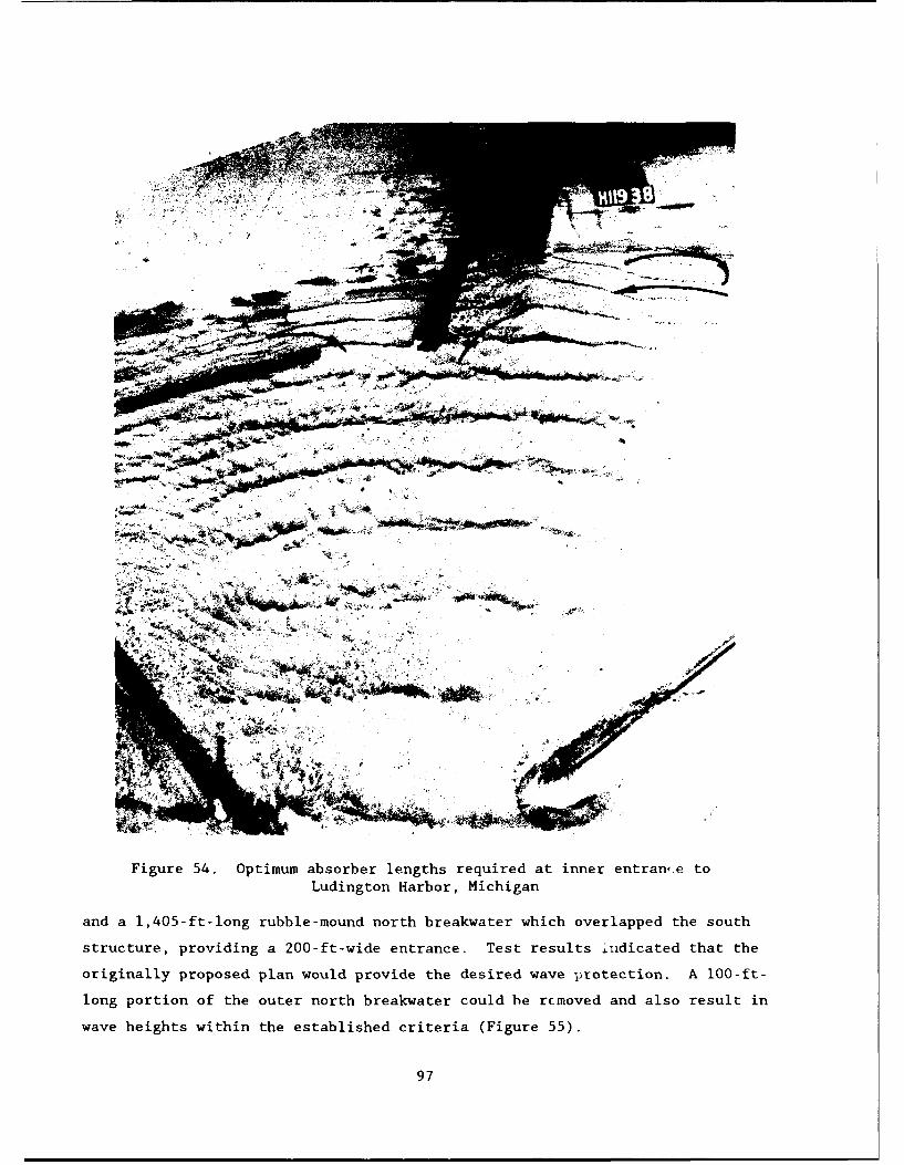
Figure 54. Optimum absorber lengths required at inner entrane toLudington Harbor, Michigan
and a 1,405-ft-long rubble-mound north breakwater which overlapped the south
structure, providing a 200-ft-wide entrance. Test results ±idicated that the
originally proposed plan would provide the desired wave protection. A lO0-ft-
long portion of the outer north breakwater could he rcmoved and also result in
wave heights within the established criteria (Figure 55).
97

Figure 55. Optimum breakwater alignment for wave protection ofNew Buffalo Harbor, Michigan
Additional configurations were tested and optimized. It was determined that
moving the outer arm of the north breakwater shoreward would provide the de-
sired wave protection with less length, however, navigation conditions would
not be as good due to sharper turns the vessels would have to make entering
the channel. A plan with a 250-ft-wide channel was optimized at the harbor
entrance by using the original north breakwater length and reducing the
length, at the lakeward end, of the south breakwater.
(Gary Harbor, Indiana
215. Gary Harbor, Indiana, is located at the southern end of Lake
Michigan, about 20 miles southeast of Chicago. The harbor consisted of a slip
about 5,500 ft long and 250 ft wide, which was partially protected from storm-
wave attack by a caisson-type breakwater extending about 3,200 ft from shore
in a northeasterly direction. A 9,700-ft-long, vertical-wall, steel sheet-
pile bulkhead and landfill were proposed along the lakefront adjacent to the
existing slip.
98

216. A 1:150-scale hydraulic model study was conducted to determine the
effect of the proposed bulkhead on wave and current conditions in the area of
Gary Harbor and to develop remedial plans for the alleviation of undesirable
wave and current effects (Housley 1959). Waves with periods of 7.2 to 9.5 sec
and heights ranging from 12 to 13.5 ft were reproduced from four directions
using a +3.1-ft swl lwd.
217. Tests were conducted for existing conditions and nine test plan
configurations. For existing conditions, wave heights during periods of storm
wave attack were almost 4 ft in the harbor slip. Installation of the verti-
cal-wall bulkhead revealed serious reflection problems with respect to navi-
gation. Tests indicated that a 4,450-ft-long rubble-mound absorber would be
necessary to prevent an increase in wave action in the navigation areas.
Model testing revealed that to significantly reduce wave heights in the slip
area, the existing breakwater would have to be extended by 600 ft and an addi-
tional breakwater would have to be constructed perpendicular to the outer arm
of the existing breakwater (Figure 56). Construction of this configuration
would reduce currents transverse to the harbor slip below those measured for
existing conditions.
Port Washington Harbor, Wisconsin
218. Port Washington Harbor is located on the west shore of Lake
Michigan about 25 miles north of Milwaukee, WI. The harbor was afforded some
protection from storm waves by a system of converging rubble and caisson-type
breakwaters forming a navigation opening 350 ft wide. The breakwater system
was 3,500-ft-long and the harbor covered about 60 acres. Waves, from direc-
tions northeast clockwise through south-southeast, had occasionally caused
considerable damage to harbor facilities. Waves passed through the navigation
opening and traveled along a vertical-wall wharf into the slip areas of the
harbor. Also, wave overtopping of the north caisson breakwater generated
hazardous conditions in the harbor for moored vessels as well as vessels navi-
gating the entrance.
219. A 1:100-scale hydraulic model investigation was conducted to de-
termine the efficiency of proposed improvement plans and develop new plans, if
necessary, to alleviate undesirable wave conditions in the harbor (Fortson
et al. 1951). Waves with periods ranging from 5.5 to 7.5 sec and heights from
10.5 to 14.5 ft were reproduced from eight directions of wave approach for a
+2.0-ft swl lwd.
99

~4 # 41
ta
Al+4? +~±Inm
77W~
Figue 5. Beakwtermodficaion reuire fo wae an curen
Lrotlc o oGr abr nin
220.Tess wee cnduted or xistng ondtion an 29 estpla
co Figuration. Theaorgially propiictonse configratifor consited of theplace-
mfent of wave ab~sorber at vnri-oiis locations in the sl ips and on the lakes ide ot
tHie north and south cais'son Ibrookwa ters. The plan was effective in reducing
breakwat-er overUtopp ing , hloweveri, energy propaga ting through tHec eit ratic e and
mIov ing into the inner has iliv resul ted in inadequiate p rot ec tion to the harbor
For Vstorm11 wave act ion . Numnerous plans were tested wh ic ci nc lidod reinova 1 of
Hthe !;olthl breakwater , in con] imtwtion with ain offshore structuvre, and a lakeward
ctir ved ex teti5 io of the north breakwater . The optimum plan ( Figur~e '-/ ) en -
tvi i led a north breakwa ter extensý ion (1I , 2 80 ft- ) and removal oft a po rt 1011 of' the
!souitb breakwater . This pl an provided -ide(jli~tate wave prott t-i(t1onl ill the inlner
lip 1I'.100

Figure 57. Optimum plan developed in the 1:100-scale model forprotection of the inner slips at Port Washington Harbor,
Wisconsin
221. Subsequent to the 1:100-scale model study, another model investi-
gation was conducted (at a 1:75 scale) to determine improvements required for
a small-boat harbor within the existing outer harbor (Bottin 1977a). Waves
with periods ranging from 5.5 to 9.4 sec and heights ranging from 3.4 to
14.7 ft were reproduced from six directions with a +3.9-ft swl. For a plan to
be acceptable to the sponsor, wave heights in the proposed small-boat harbor
were not to exceed 2.0 ft in the turning basin and 1.0 ft in the mooring
areas.
222. The originally proposed improvement plan included a 1,010-ft-long
west breakwater, a 320-ft-long east breakwater, and a 500-ft-long wave ab-
sorber adjacent to the shoreward side of the existing north breakwater. Test
results indicated that the established wave height criterion would be exceeded
for test waves from all directions. Observations revealed excessive over-
topping of the existing north breakwater (adjacent to the new harbor) and
overtopping of and transmission through the proposed east and west break-
waters. It was determined, by testing of numerous improvement plans, that a
101
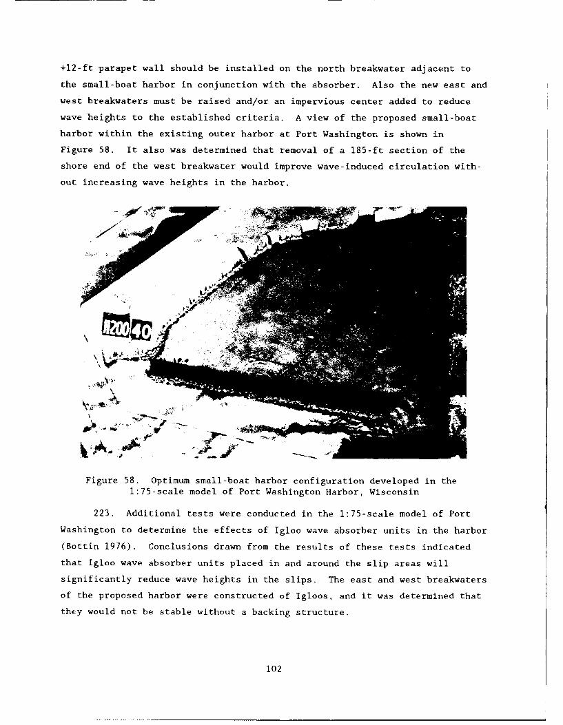
+12-ft parapet wall should be installed on the north breakwater adjacent to
the small-boat harbor in conjunction with the absorber. Also the new east and
west breakwaters must be raised and/or an impervious center added to reduce
wave heights to the established criteria. A view of the proposed small-boat
harbor within the existing outer harbor at Port Washington is shown in
Figure 58. It also was determined that removal of a 185-ft section of the
shore end of the west breakwater would improve wave-induced circulation with-
out increasing wave heights in the harbor.
Figure 58. Optimum small-boat harbor configuration developed in the1:75-scale model of Port Washington Harbor, Wisconsin
223. Additional tests were conducted in the 1:75-scale model of Port
Washington to determine the effects of Igloo wave absorber units in the harbor
(Bottin 1976). Conclusions drawn from the results of these tests indicated
that Igloo wave absorber units placed in and around the slip areas will
significantly reduce wave heights in the slips. The east and west breakwaters
of the proposed harbor were constructed of Igloos, and it was determined that
they would not be stable without a backing structure.
102

Little Lake Harbor, Michigan
224. Little Lake Harbor is a harbor-of-refuge located on Lake Superior
about 30 miles east of Grand Marais, MI. The project consisted of a 1,000-ft-
long dogleg west breakwater and a 270-ft-long east breakwater with an 80-ft-
wide channel dredged between Little Lake and Lake Superior. Severe shoaling
occurred at the harbor entrance that made navigation to the protective harbor
both difficult and dangerous even during relatively mild weather conditions.
Entrance shoaling was caused by wave action moving material alongshore, and
seiche activity in Lake Superior created currents through the entrance and may
have influenced sediment movement.
225. A 1:75-scale hydraulic model investigation was conducted to devel-
op the most economical plan of improvement that would minimize channel shoal-
ing without adversely impacting navigation (Seabergh and McCoy 1982). Waves
with periods ranging from 5 to 9 sec and heights from 4 to 21 ft were repro-
duced from six directions of wave approach with a +1.0-ft swl lwd. Equipment
also was calibrated and utilized to reproduce seiche activity (seiche heights
in Little Lake and seiche currents through the entrance) in the model based on
prototype data obtained.
226. Tests were conducted for existing conditions and 15 test plans
consisting of structural modifications at the entrance. Existing conditions
revealed that shoaling problems existed as a result of the influx of sediment
along the east breakwater and eastern portion of the channel. Sediment was
deposited by wave action from all directions. For waves from north to west,
sediment moved due to the circulation gyre developed in the lee of the west
breakwater, and for other wave directions, the incident longshore conditions
caused the shoal.
227. The originally proposed improvement plan, consisting of a signifi-
cant extension (900 ft) of east breakwater, appeared to have created a sedi-
ment trap inside the jetties and actually increased shoaling when compared to
existing conditions. Plans with structures extending to the bar that bypasses
the harbor would intercept sediment movement and shoaling of the entrance
occurred. It was determined that a 570 ft structure eastward of the east
breakwater would reduce shoaling and provide good bypassing characteristics in
both dirtctions. The plan (Figure 59) also reduced seiche oscillations in the
harbor and velocities in the entrance channel.
103
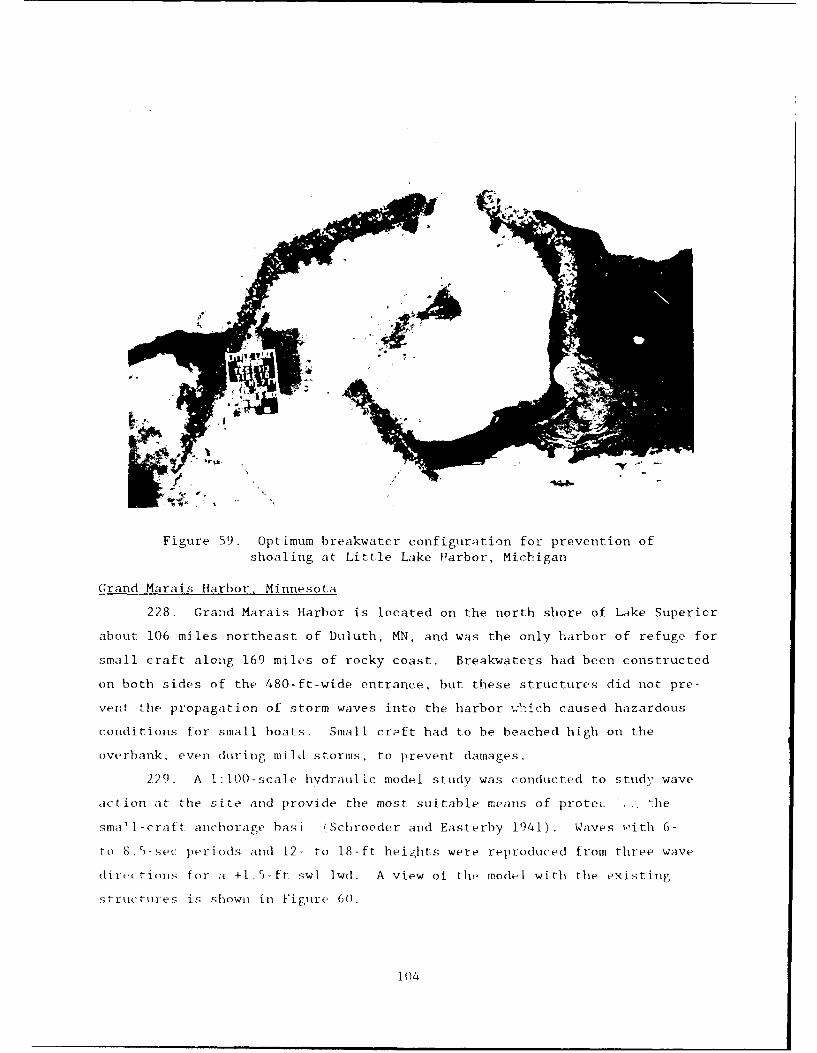
SiP
Figure 59. Optimum breakwater configuration for prevention ofshoaling at Little Lake Harbor, Michigan
Grand Marais Harbor, Minnesota
228. Grand Marais Harbor is located on the north shore of Lake Superior
about 106 miles northeast of Duluth, MN, and was the only harbor of refuge for
small craft along 169 miles of rocky coast. Breakwaters had been constructed
on both sides of the 480-ft-wide entrance, but these structures did not pre-
vent the propagation of storm waves into the harbor '.:hich caused hazardous
conditions for small boats. Small crqft had to be beached high on the
overbank, even during mild storms, to prevent damages.
229. A 1:100-scale hvdraulic model study was conducted to study wave
action at the site and provide the most suitable means of protec -. The
sma11-craft anchorage hasi (Schroeder and Easterby 1941). Waves with 6-
to 8.5-se- periods and 12- to 18-ft heihts were reproduced from three wave
direictions for a +1.5-ft swl lwd. A view of tht, model with the existing
structules is shown in Figure 6(0.
104
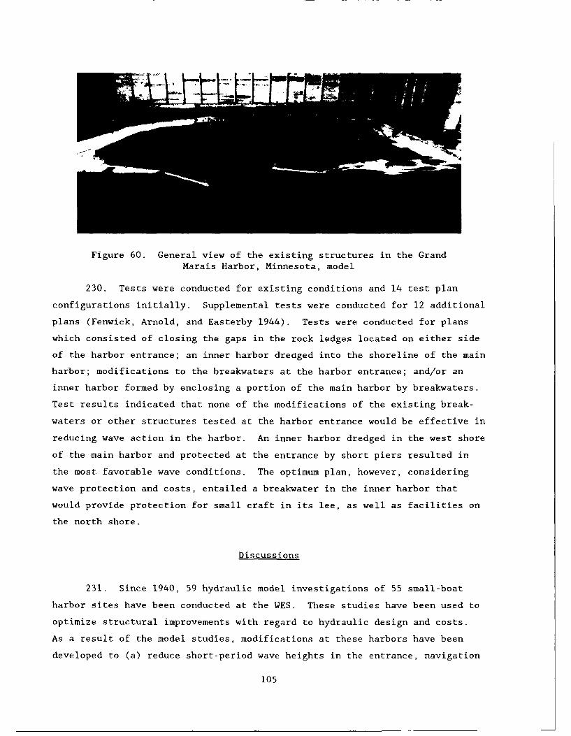
Figure 60. General view of the existing structures in the GrandMarais Harbor, Minnesota, model
230. Tests were conducted for existing conditions and 14 test plan
configurations initially. Supplemental tests were conducted for 12 additional
plans (Fenwick, Arnold, and Easterby 1944). Tests were conducted for plans
which consisted of closing the gaps in the rock ledges located on either side
of the harbor entrance; an inner harbor dreaged into the shoreline of the main
harbor; modifications to the breakwaters at the harbor entrance; and/or an
inner harbor formed by enclosing a portion of the main harbor by breakwaters.
Test results indicated that none of the modifications of the existing break-
waters or other structures tested at the harbor entrance would be effective in
reducing wave action in the harbor. An inner harbor dredged in the west shore
of the main harbor and protected at the entrance by short piers resulted in
the most favorable wave conditions. The optimum plan, however, considering
wave protection and costs, entailed a breakwater in the inner harbor that
would provide protection for small craft in its lee, as well as facilities on
the north shore.
Discussions
231. Since 1940, 59 hydraulic model investigations of 55 small-boat
harbor sites have been conducted at the WES. These studies have been used to
optimize structural improvements with regard to hydraulic design and costs.
As a result of the model studies, modifications at these harbors have been
developed to (a) reduce short-period wave heights in the entrance, navigation
105

channels, and mooring areas; (b) improve long-period wave conditions in moor-
ing areas; (c) reduce standing waves in harbors; (d) reduce crosscurrents
across navigation paths; (e) increase wave-induced circulation inside harbor
areas; (f) minimize or eliminate harbor entrance shoaling due to wave-induced
longshore currents and tidal currents; (g) stabilize harbor inlet openings;
(h) determine locations of deposition basins at inlet entrances; (i) optimize
tidal current flows through inlets; (j) improve flood and ice flows through
the harbors and their entrances; and (k) determine effects of structures on
thermal conditions.
232. Of the 59 model investigations conducted, 17 were conducted for
proposed harbor sites where unimproved conditions existed, and 42 were con-
ducted at existing harbor sites where structures existed. Some of these sites
included expansions of the existing harbor, however, most studies were con-
ducted to develop remedial plans of improvement where problems existed. Test
results for the originally proposed designs for the 59 model studies indicated
that 46 proposed designs were ineffective in achieving the desired results,
and therefore, subsequent modifications were required in the model to make the
design functionally acceptable. Of the 13 originally proposed designs that
met the established criteria, 10 projects were over designed. Model tests for
these 10 harbor sites indicated the original structure lengths could be re-
duced, crest elevations lowered, etc. and still provide the desired protection
required, thus construction costs were reduced. Of the 59 hydraulic model
investigations conducted, only three of the originally proposed designs pro-
vided adequate protection without modification. Model tests verified that
these improvements could be made without sacrificing harbor protection, and
that reductions in structure length, etc., in an effort to reduce costs, could
not be made.
233. In review, most of the earlier model studies, generally, were
conducted at smaller scales than the more current investigations. It also
appears that design conditions of earlier studies were less severe than the
design conditions for present studies in similar geographical areas. Some of
the earlier studies used impervious breakwaters to represent rubble-mound
breakwaters because the transmission of short-period wave energy through these
structures was negligible. Subsequent experience has shown that considerable
energy may pass through rubble-mound structures, and steps are currently
taken, based on scale effect testing conducted at WES, to adjust stone sizes
106

so that correct transmission and reflection characteristics are reproduced.
The earlier studies examined, in most cases, a single problem (i.e. wave
conditions). Model studies today are very comprehensive and test numerous
conditions (i.e. wave conditions; current conditions; flood, ice, and tidal
flows; shoaling conditions; effects of improvements on thermal conditions,
etc.). In summary, the capabilities of physical models have been improved
through the years, and test conditions have become more representative of
prototype conditions through the use of unidirectional and directional spec-
tral wave machines which can produce more realistic wave conditions as com-
pared to old monochromatic wave generating equipment. Also, the use of high-
speed computers to control laboratory equipment and collect and analyze data
permits studies to consider much larger sets of prototype conditions than
could be addressed in model studies prior to the 1970's. Improvements in
laboratory sensors have allowed higher resolution and more reliable laboratory
measurements and with the advent of laser and ultrasonic sensors detailed
measurements of current and velocity fields are now possible where they could
only be defined in approximations in the past. The state of the art for
hydraulic model investigations is constantly improving.
107
PART III: PHYSICALLY MODELED HARBORS WHICH HAVE BEEN CONSTRUCTED
Inventory
234. Physical model investigations of 55 small-boat harbor projects in
the United States and/or its territories have been conducted at WES. Of the
55 projects, 25 have been constructed in the prototype based on model test
results. The physically modeled harbors which have been constructed in the
prototype are listed. The number adjacent to the harbor site corresponds to
the location shown in Figure 1.
1 Agana Small-Boat Harbor, Territory of Guam
2 Taut Harbor, Island of Taui, American Samoa
3 Waianae Small-Boat Harbor, Oahu, Hawaii
7 Laupahoehoe Point, Hawaii
8 St. Paul Harbor, St. Paul Island, Alaska
9 Siuslaw River, Oregon
12 Crescent City Harbor, California
14 Fisherman's Wharf, San Francisco Bay, California
15 Half Moon Bay Harbor, California
21 Marina del Rey, California
25 Dana Point Harbor, California
30 Murrells Inlet, South Carolina
31 Little River Inlet, South Carolina
32 Masonboro Inlet, North Carolina
39 Port Ontario Harbor, New York
40 Oswego Harbor, New York
43 Cattaraugus Creek Harbor, New York
44 Barcelona Harbor, New York
45 Conneaut Harbor, Ohio
46 Geneva-on-the-Lake Small-Boat Harbor, Ohio
49 Vermilion Harbor, Ohio
50 Ludington Harbor, Michigan
51 New Buffalo Harbor, Michigan
53 Port Washington Harbor, Wisconsin
55 Grand Marais Harbor, Minnesota
108

Site Specific Construction and Performance
235. In this portion of the report, the 25 small-boat harbor projects
which have been modeled at WES and subsequently constructed in the prototype
are discussed. A description of the structural features of the prototype
harbor are presented and model test plans are reviewed to determine if the
prototype harbor modifications were, in fact, those tested and recommended in
the model study. Also briefly discussed are the performances of the various
harbor sites since construction. A detailed, in-depth, study of harbor per-
formance was not conducted. Information on harbor performance was obtained
from various Corps of Engineer District personnel familiar with the projects,
the "Monitoring Completed Coastal Projects" (MCCP) program administered by the
Corps of Engineers, and local harbor personnel, harbor users, and newspaper
articles. The information contained herein gives an indication of how the
projects have performed and includes problems that may have been encountered
since construction.
Agana Small-BoatHarbor, Territory of Guam
236. In 1977 the existing Agana Small-Boat Harbor was expanded. A
1,135-ft revetted mole was constructed with provisions for additional berthing
area on its shoreward side. A sewage treatment plant also was constructed
west of the mole. To minimize navigational difficulties, a 525-ft-long west
breakwater and a 200-ft-long east breakwater were installed at the entrance.
In addition, a 250-ft-long rubble-wave absorber was constructed inside the
harbor entrance to dampen wave energy that may otherwise propagate, or be
reflected, into the proposed mooring areas. A view of the completed harbor is
shown in Figure 61. Prior to the expansion, Agana was experiencing naviga-
tional problems due to a sharp reverse bend in the entrance channel and
wave-induced crosscurrents.
237. A review of the model investigation of Agana Small-Boat Harbor
(Chatham 1975) indicated that a 650-ft-long west breakwater and a 325-ft-long
east breakwater were recommended to minimize crosscurrents and confused wave
patterns in the entrance. The lengths of each of these structures were 125 ft
longer than those built in the prototype. The alignment of the breakwaters
constructed at the site, however, were the same as recommended in the model.
109

Figure 61. Agana Small-Boat Harbor, Agana,Guam
Also, the model was tested with a 500-ft-long wave absorber inside the
entrance as opposed to the 250-ft-long structure constructed in the prototype.
An arrangement of open channels was determined in the model to provide ade-
quate circulation in the berthing areas of the harbor. Circulation channels
were constructed in the prototype; however, the proposed new mooring areas
tested in the model have not yet been developed at the site. The sewage
treatment plant constructed at the site (west of the mole) was the same as
tested at a seaward location in the model. A shoreward location was also
tested.
238. An assessment of post construction performance of wave conditions
in the proposed mooring areas cannot be made since this development has not
vet been constructed. No berthing problems have been encountered in the ex-
isting small boat mooring area; however, this area is well protected from
waves by the new breakwaters and mole section. Even though the breakwater
lengths constructed in the prototype were shorter than those tested in the
model, the breakwaters are very effective in minimizing crosscurrents and
improving navigation conditions in the new entrance. The breakwaters tend to
110

deflect wave-induced currents moving along the reef in a seaward direction,
thus preventing crosscurrents in the channel. The small craft using the
existing berthing areas at Agana are not experiencing navigation problems at
the entrance. Current conditions in the harbor entrance appear to be reacting
as predicted by the model. It has also been noted that the channels con-
structed at the site are very effective in providing circulation in the
proposed berthing areas.
Tau Harbor, Island
of Tai. American Samoa
239. Construction of Ta'i Harbor was completed in 1981. It consisted of
a rectangular basin enclosed by a revetted landfill and a 290-ft-long break-
water on the east and a 200-ft-long groin on the west (Figure 62). The harbor
was constructed for the loading and unloading of cargo and personnel trans-
ported between the islands by an interisland tug and barge network. No harbor
existed on the island until construction of Tati Harbor.
Figure 62. Tau Small-Boat Harbor, Taui Island, American Samoa
240. A review of the model investigation of Tau Harbor (Crosby 1974)
revealed that the harbor structures were constructed in the prototype based on
111

the plan recommended by the model study. It is noted, however, that the en-
trance channel tested in the model was 100 ft wide, 14 ft deep, with a 12-ft-
deep turning basin. In the prototype, the entrance channel is 130 ft wide and
16 ft deep and the turning basin was dredged to a 14-ft depth. None of the
plans tested in the model satisfied the 3.0-ft wave height criterion in the
berthing area for all test waves; however, the plan that was constructed in
the prototype came closest to meeting the criterion. The harbor was not
designed to be an all-weather harbor and conclusions of the study stated that
the plan would be acceptable only if it was recognized that there would be
periods when the harbor would not be usable. The model also indicated wave-
induced currents in the entrance ranging up to 4.7 fps for 5-ft incident waves
and up to 7.1 fps for 15-ft incident waves. It was also recognized in the
study that when waves are breaking across the entrance or crosscurrents are
present, vessels would not be able to leave or enter the harbor.
241. A review of the performance of Tau' Harbor since construction re-
veals that vessels experience navigation problems in the entrance channel.
Waves approach and break over the reef on both sides of the entrance channel
and spill into it making it difficult for vessel operators to identify the
channel limits. Wave-induced currents, due to waves breaking across the reef,
also present navigational difficulties. The use of the harbor is limited due
to these phenomena. Excessive wave heights in the berthing area also occur at
times, but are not as prohibitive as the undesirable conditions in the en-
trance. The model study indicated that the plan built in the prototype was
the best that was tested, but it also predicted excessive wave heights in the
berthing area at times and periods when navigation conditions would not be
favorable due to breaking waves and crosscurrents in the entrance channel.
For available funds, the best harbor configuration was constructed, but it is
not, nor was it recognized as, an all-weather harbor.
Waianae Small-Boat Harbor, Oahu, Hawaii
242. Construction of a 1,690-ft-long main breakwater and a 220-ft-long
stub breakwater at Waianae were completed in 1979 (Figure 63). The Waianae
coast provides some of the best fishing in the Hawaiian islands and is an
excelient boating area. The new harbor provided much needed small-craft
berthing facilities in this vicinity.
243. A review of the model investigation at Waianae (Bottin, Chatham
and Carver 1976) indicated that the prototype harbor was constructed similar
112

Figure 63. Waianae Small-Boat Harbor, Oahu, Hawaii
to the optimum configuration tested in model, but discrepancies did exist.
The model revealed an optimum outer breakwater length of 1,650 ft and a spur
breakwater length of 250 ft. The outer breakwater constructed at the site was
40 ft longer than recommended in the model, and the stub breakwater was 30 ft
shorter than that recommended. The longer outer breakwater provided more
overlap of the entrance, but the shorter stub structure resulted in an en-
trance opening that was wider than recommended. The breakwater cross sections
and crest elevations recommended in the model were the same as those con-
structed in the prototype. The plan was developed in the model to achieve a
wave height criterion of 2.0 ft in the berthing areas.
244. A review of the performance of Waianae Harbor after construction
reveals complaints relative to the harbor. There are no indications of vessel
or facility damage, but excessive movement of the vessels in the slip areas is
a nuisance and aggravating to boat owners. Complaints have also been received
regarding undesirable wave conditions at the boat ramp located immediately
inside the entrance. The harbor users' complaints are not during periods of
storm conditions but for conditions that occur on a day-to-day basis.
113

Excessive wave energy enters the harbor for normal seas. The wider entrance
channel width constructed in the prototype may contribute to some of the ex-
cess wave energy entering the harbor, however, the selected 2.0-ft wave height
criterion that the harbor was designed for was probably excessive. Currently,
most small-boat harbors are currently designed for a 1.0-ft wave height
criterion in the mooring areas during storm wave conditions. A review of the
model tests indicates that for 4-ft incident test waves (common conditions),
wave heights in the mooring areas could range from 1.1 to 1.6 ft depending on
the wave period and direction of approach. For storm waves (8 to 12 ft in
height), the model met the criterion of 2.0 ft, but for more common conditions
wave heights up to 1.6 ft could occur (greater than the current criteria for
storm conditions in most small-craft harbors). Most Hawaiian small-boat har-
bors also have fixed docks, since the tidal range is relatively small. With
the mooring line configuration at Waianae, vessels are taunt at low tide, but
at high water their lines have slack which allows more freedom for movement.
Small craft in the harbor, therefore, move more in their slips at the higher
water levels as they ride the crests of the incoming waves. The model indi-
cated wave heights ranging from 1.0 to 1.8 ft at the boat launching ramp for
4-ft incident wave conditions from the most predominant wave direction.
Prototype conditions may result in greater heights, however, since the stub
breakwater at the site is shorter than that recommended in the study, which
may allow more wave energy to the ramp location. Excessive wave heights at
Waianae do occur for normal wave conditions, but upon close examination, the
model tests predicted these. The primary problem was that the 2.0-ft design
wave height criterion probably was too high, especially with the slack mooring
line conditions that occur during the tidal cycle due to the fixed, as opposed
to free floating docks. The boat launching ramp also should be in a more
protected area in the harbor than its current location directly inside the
entrance.
Laupahoehoe Point. Hawaii
245. In 1988, improvements were completed at Laupahoehoe Point, Hawaii,
to provide a protected boat-launching ramp. Construction of a 200-ft-long
rubble-mound breakwater (seaward end having a rib cap and armored with
dolosse), a 60-ft-long wave absorber installed adjacent to the shoreline, an
entrance channel, and a turning basin were included. These improvements would
allow local fishermen to take full advantage of the ocean's resources in the
114

immediate area. A view of the completed project is shown in Figure 64. Prior
to improvements, the project was model tested.
* S
Figure 64. Laupahoehoe Boat Launching Facility, Hawaii
246. A review of the model investigation at Laupahoehoe Point (Bottin,
Markle, and Mize 1987) indicated that the proposed project was constructed as
recommended in the model. Wave heights at the boat ramp were not to exceed
2 ft for normal wave conditions (deepwater waves of 6 ft or less). Wave
heights within this criterion were expected to render the launching ramp us-
able approximately 70 percent of the time. Due to year-round rough water
conditions, a facility designed for 100-percent usage was not economically
feasible.
247. The performance of the Laupahoehoe Boat Launching Facility since
construction indicates that the ramp is not usable a large portion of the
time. Laupahoehoe is in an area of relatively high wave energy. Waves with
heights of 4 to 6 ft are normal and occur almost constantly at the site. The
launching facility was designed with a wave height criterion of 2.0 ft for
notmal wave conditions. Observations in the prototype indicate that waves
ranging from 1.5 to 2.0 ft result in breaking conditions on the boat ramp that
115

cause unsafe launching conditions. The model predicted wave heights of 2.0 ft
or less for approximately 70 percent of the time (based on hindcast data).
Since the boat ramp can rarely be used when 2-ft waves are present, due to
breaking conditions, it appears that the established wave height criterion was
excessive. Despite the fact that the boat launching ramp is not usable as
great a percentage of time as expected, local users appear to be content with
the project for the benefits that are derived (mostly fishing benefits).
St. Paul Harbor, St. Paul Island, Alaska
248. A breakwater was constructed at St. Paul Harbor during the early
1980's but subsequently failed during storms of 1984. A new breakwater was
completed at the site in 1985. This breakwater was 750 ft in length. It
functioned well with regard to stability, but was not of sufficient length to
provide wave protection to vessels utilizing a dock, which was adjacent to the
harbor side of the structure. In 1989, construction of a breakwater extension
and a secondary breakwater at St. Paul Harbor was completed. The breakwater
extension was 1,050 ft in length and the detached secondary breakwater was
1,000-ft-long. A view of these structures while under construction is shown
in Figure 65. The 1989 improvements were model tested prior to construction.
Figure 65. St. Paul Harbor structures during construction
116
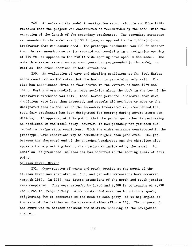
249. A review of the model investigation report (Bottin and Mize 1988)
revealed that the project was constructed as recommended by the model with the
exception of the length of the secondary breakwater. The secondary structure
recommended in the model was 1,100 ft long as opposed to the 1,000-ft-long
breakwater that was constructed. The prototype breakwater was 100 ft shorter
t.ian the recommended one at its seaward end resulting in a navigation opening
of 350 ft, as opposed to the 250-ft-wide opening developed in the model. The
outer breakwater extension was constructed as recommended in the model, as
well as, the cross sections of both structures.
250. An evaluation of wave and shoaling conditions at St. Paul Harbor
since construction indicates that the harbor is performing very well. The
site has experienced three to four storms in the winters of both 1989 and
1990. During storm conditions, wave activity along the dock in the lee of the
breakwater extension was calm. Local harbor personnel indicated that wave
conditions were less than expected, and vessels did not have to move to the
designated area in the lee of the secondary breakwater (an area behind the
secondary breakwater has been designated for mooring during severe storm con-
ditions). It appears, at this point, that the prototype harbor is performing
as predicted in the model study, however, it has probably not yet been sub-
jected to design storm conditions. With the wider entrance constructed in the
prototype, wave conditions may be somewhat higher than predicted. The gap
between the shoreward end of the detached breakwater and the shoreline also
appears to be providing harbor circulation as indicated by the model. In
addition, as predicted, no shoaling has occurred in the mooring areas at this
point.
Siuslaw River, Oregon
251. Construction of north and south jetties at the mouth of the
Siuslaw River was initiated in 1893, and periodic extensions have occurred
through 1985. In 1985, the latest extensions of the north and south jetties
were completed. They were extended by 1,900 and 2,300 ft to lengths of 9,990
and 6,245 ft, respectively. Also constructed were two 400-ft-long spurs,
originating 900 ft shoreward of the head of each jetty, at 45-deg angles to
the axis of the jetties on their seaward sides (Figure 66). The purpose of
the spurs was to deflect sediment and minimize shoaling of the navigation
channel.
117
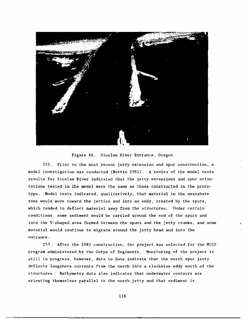
Figure 66. Siuslaw River Entrance, Oregon
252. Prior to the most recent jetty extension and spur construction, a
model investigation was conducted (Bottin 1981). A review of the model tests
results for Siuslaw River indicated that the jetty extensions and spur orien-
tations tested in the model were the same as those constructed in the proto-
type. Model tests indicated, qualitatively, that material in the nearshore
zone would move toward the jetties and into an eddy, created by the spurs,
which tended to deflect material away from the structures. Under certain
conditions, some sediment would be carried around the end of the spurs and
into the V-shaped area formed between the spurs and the jetty trunks, and some
material would continue to migrate around the jetty head and into the
entrance.
253. After the 1985 construction, the project was selected for the MCCP
program administered by the Corps of Engineers. Monitoring of the project is
still in progress, however, data to date indicate that the north spur jetty
deflects longshore currents from the north into a clockwise eddy north of the
structures. Bathymetry data also indicates that underwater contours are
orienting themselves parallel to the north jetty and that sediment is
118
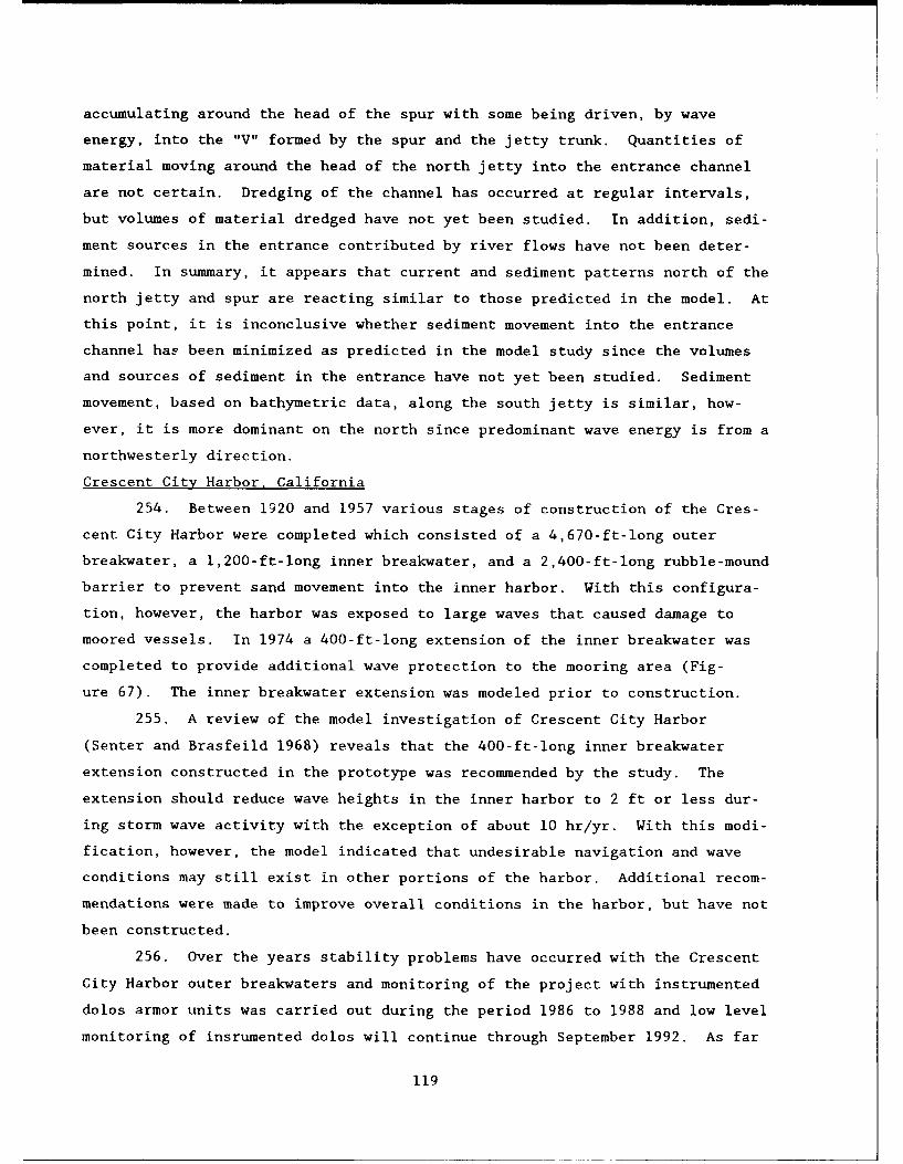
accumulating around the head of the spur with some being driven, by wave
energy, into the "V" formed by the spur and the jetty trunk. Quantities of
material moving around the head of the north jetty into the entrance channel
are not certain. Dredging of the channel has occurred at regular intervals,
but volumes of material dredged have not yet been studied. In addition, sedi-
ment sources in the entrance contributed by river flows have not been deter-
mined. In summary, it appears that current and sediment patterns north of the
north jetty and spur are reacting similar to those predicted in the model. At
this point, it is inconclusive whether sediment movement into the entrance
channel hap been minimized as predicted in the model study since the volumes
and sources of sediment in the entrance have not yet been studied. Sediment
movement, based on bathymetric data, along the south jetty is similar, how-
ever, it is more dominant on the north since predominant wave energy is from a
northwesterly direction.
Crescent City Harbor, California
254. Between 1920 and 1957 various stages of construction of the Cres-
cent City Harbor were completed which consisted of a 4,670-ft-long outer
breakwater, a 1,200-ft-long inner breakwater, and a 2,400-ft-long rubble-mound
barrier to prevent sand movement into the inner harbor. With this configura-
tion, however, the harbor was exposed to large waves that caused damage to
moored vessels. In 1974 a 400-ft-long extension of the inner breakwater was
completed to provide additional wave protection to the mooring area (Fig-
ure 67). The inner breakwater extension was modeled prior to construction.
255. A review of the model investigation of Crescent City Harbor
(Senter and Brasfeild 1968) reveals that the 400-ft-long inner breakwater
extension constructed in the prototype was recommended by the study. The
extension should reduce wave heights in the inner harbor to 2 ft or less dur-
ing storm wave activity with the exception of about 10 hr/yr. With this modi-
fication, however, the model indicated that undesirable navigation and wave
conditions may still exist in other portions of the harbor. Additional recom-
mendations were made to improve overall conditions in the harbor, but have not
been constructed.
256. Over the years stability problems have occurred with the Crescent
City Harbor outer breakwaters and monitoring of the project with instrumented
dolos armor units was carried out during the period 1986 to 1988 and low level
monitoring of insrumented dolos will continue through September 1992. As far
119
- CG1
-Iir
Figure 67. Crescent City Harbor, California
as problems associated with adverse waves and/or vessel damage in the mooring
area, however, none have been reported since construction of the 400-ft-long
inner breakwater extension. The mooring area appears to be quiet during storm
wave activity as predicted by the model study.
Fisherman's Wharf,San Francisco Bay, California
257. Construction of a 1,509-ft-long solid, concrete-pile breakwater
was completed at Fisherman's Wharf in 1986. In addition, two segmented break-
waters (28-ft solid walls with 6-ft openings) were constructed. These latter
two structures were 150 and 258 ft long and were built along Pier 45. The
breakwater system (Figure 68) was constructed to provide wave protection to
the harbor during storm wave conditions. The segmented structures permitted
tidal currents to pass through the harbor for flushing. Prior to construc-
tion, wave energy resulted in continual damage to fishing vessels and mooring
facilities in the area. The harbor configuration was model tested to optimink*
structure designs prior to construction.
120

Figure 68. Fisherman's Wharf Harbor, San Francisco, California
258. A review of the model investigation of Fisherman's Wharf Area
(Bottin, Sargent, and Mize 1985) revealed that the prototype harbor was con-
structed similar to the configuration developed and recommended in the model.
A 1,585-ft-long solid breakwater was recommended in the model study, as op-
posed to the 1,509-ft-long structure constructed in the prototype. The end
points of the prototype harbor breakwater, however, were in the exact relative
locations as those tested in the model. The length difference resulted
because the curved breakwater tested in the model was replaced with short
straight sections in the prototype. The location of the segmented structures
constructed in the prototype were the same as in the model study. Since the
end points of the solid breakwater were in the same relative locations and the
segmented structures were the same, the results from the model study should be
applicable when compared to the prototype.
259. Since construction of the project in the prototype, several storms
have occurred and wave conditions along the historic fleet mooring area and
the inner basins have been relatively calm with no reports of damage. The
project won an engineering design Award of Merit in the 1989 Chief of
121

Engineers Design and Environmental Awards Program. It was stated that the
modeling effort yielded a highly efficient system of three separate break-
waters which minimize physical size and cost, yet provide protection from
storms from several different directions. The project was also selected for
the MCCP program. Monitoring of the project is currently in progress, and
data obtained to date indicate that the completed project is performing as
intended.
Half Moon Bay Harbor, California
260. In 1961, construction of two rubble-mound, shore-connected break-
waters was completed at Half Moon Bay Harbor to protect the harbor during
severe storms. The west breakwater was 2,620 ft long, and the east breakwater
was 4,420 ft long. After construction, however, storm waves frequently caused
the berthing areas to be unusable and indicated the structures did not provide
adequate wave protection. A 1,050-ft-long extension of the west breakwater
was completed in 1967 to alleviate undesirable wave conditions in the harbor
(Figure 69). The breakwater extension was modeled prior to construction.
Figure 69. Half Moon Bay Harbor, California
261. A review of the model investigation of Half Moon Bay Harbor
(Wilson 1965) indicated that the 1,050-ft-long structure was recommended to
122

provide the desired protection in the prototype. The length and orientation
of the breakwater extension was constructed in the prototype as recommended by
the model. The extension was predicted to reduce wave heights to within a
2.0-ft wave height criterion established by the sponsor for storm wave
conditions.
262. After construction of the 1,050-ft-long breakwater extension at
Half Moon Bay Harbor, small boats were provided adequate protection for open
mooring in the harbor. The 2-ft wave height criterion in the harbor, however,
was not adequate for mooring small craft in a marina type environment. Subse-
quent to construction of the breakwater extension, the San Mateo Harbor Dis-
trict developed a marina inside the harbor which was enclosed by rubble-mound
breakwaters. The marina was designed so that maximum wave heights would not
exceed 1.0 ft during storm wave conditions. The model prediction of 2.0-ft
waves in the harbor were correct according to prototype observations during
storm events.
Marina del Rey, California
263. In the early 1960's two parallel jetties about 2,000 ft long were
constructed to provide protection to Marina del Rey, a small-craft harbor
developed by dredging a 2-mile-long channel and eight lateral basins off the
main channel. After construction of the marina, waves entering the entrance
resulted in intolerable wave conditions in several of the basins. Subse-
quently, a 2,330-ft-long detached breakwater was constructed (Figure 70) to
provide the desired wave protection. The detached breakwater was modeled
prior to construction.
264. A review of the model investigation of Marina del Rey (Brasfeild
1965a) revealed that the detached structure built in the prototype was essen-
tially the same as that recommended in the model. The only difference is that
the length of the prototypr structure was 5 ft longer than that recommended
(2,330 versus 2,325 ft). The location, orientation, and wing lengths, etc.
were constructed as recommended. (The additional 5 ft of structure was added
to the southern wing.) The model study did, however, recommend also that the
middle jetty be sealed to an elevation of +8-ft mllw. It was predicted that
these improvements would reduce waves in the harbor areas to heights of less
than 2 ft.
265. A review of the performance of Marina del Rey reveals that the
detached structure has been effective in reducing wave conditions in the
123

J,.
-U
Figure 70. Marina del Rey, California
harbor mooring areas to tolerable levels. Marina del Rey is considered the
world's largest man-made small-craft harbor with approximately 6,000 berthing
slips. Since construction of the detached breakwater, with the exception of
some congestion in the entrance, problems have not been encountered in the
harbor. The harbor has performed as predicted by the physical model study.
Dana Point Harbor, California
266. Construction of Dana Point Harbor was completed in 1968. It con-
sisted of a 5,500-ft-long west breakwater, a 2,250-ft-long east breakwater,
and inner harbor berthing areas partially enclosed by the shoreline and mole
sections (Figure 71). The harbor was constructed in a sheltered cove in the
lee of Dana Point and provides mooring facilities for about 2,150 small boats.
267. Prior to construction of the harbor, a model investigation was
conducted (Wilson 1966). A review of the study reveals that the harbor was
built in accordance with the recommendations of the model. The model pre-
dicted that wave heights in the berthing area5s would not exceed 1.5 ft during
storm wave activity. It was determined in the model tests, however, that at
infrequent intervals, and for short durations, wave heights in the fairway
124

Figure 71. Dana Point Harbor, California
between the west breakwater and the mole could be severe (i.e. about 8 ft) due
to wave overtopping of the breakwater.
268. An assessment of the post construction performance of wave condi-
tions at Dana Point Harbor reveals no wave related problems in the mooring
areas. Construction of the mooring areas shoreward of the moles appears to be
a good harbor design. The outer west breakwater is overtopped by storm waves,
which propagate into the revetted moles. Vessels in the mooring areas in the
lee of the moles remain protected. During periods of storm wave activity,
when other small-boat harbor facilities and small craft in Southern California
have received severe damages, Dana Point has reported none. The project is
performing as predicted by the model investigation.
Murrells Inlet, South Carolina
269. During the period 1977 to 1981, design improvements were made at
Murrells Inlet. They consisted of a north jetty with a low-crested weir sec-
tion, a sclith jetty, and sand dikes composed of dredged material which tied
the structures into the existing dune lines (Figure 72). Prior to improve-
ments, difficult and dangerous navigation conditions existed due to shifting
125

Figure 72. Murrells Inlet, South Carolina
shoals and breaking waves.
270. Before improvements were constructed, a model investigation was
conducted (Perry, Seabergh, and Lane 1978). A review of the study reveals
some discrepancies between the recommended improvements and the structures
actually constructed in the prototype. The model recommended a 3,455-ft-long
north jetty with a 1,330-ft-long low-crested weir section. In the prototype,
a 3,420-ft-long north jetty was constructed with a 1,350-ft-long low-crested
weir section. The elevations of both the north jetty (+9-ft mean low water
(mlw)) and the weir section (+2.2-ft mlw) constructed were the same as recom-
mended in the prototype. The length of the south jetty construction wa"
3,330 ft versus 3,320 ft recommended in the model, both with elevations of
+9-ft mlw. The sand dikes connecting the shoreward ends of the north and
south jetties to the existing dune line were recommended, as well as the
600 ft spacing between the jetties constructed in the prototype. The model
results also recommended a variable height training dike (el +2.3- to
126

+9-ft mlw) approximately 1,500 ft long to prevent the migration of tidal flow
through the deposition basin. The training dike was not constructed in the
prototype. In summary, most of the improvements constructed were similar to
those recommended in the model. The jetty spacing and elevations were the
same, only the lengths are slightly different. The major discrepancy was the
absence of the training dike that was recommended in the model.
271. A review of the prototype performance of the Murrells Inlet's
structures reveals that the channel between the jetties has remained stable.
The channel maintains its authorized depth and no channel dredging in this
area has been required since construction. As intended, sediment from the
north shore moves over the weir section in the jetty with the majority set-
tling into the deposition basin, which is dredged periodically. A problem,
however, has been encountered shoreward of the deposition basin. At higher
tide levels, some material passing over the weir section of the north jetty
migrates shoreward due to wave penetration. The sediment is influenced by
tidal currents in the inlet channel extending northward. A meandering un-
stable channel condition occurs in this location. At times a tip shoal forms
that directs ebb tidal flows toward the south overbank where scouring occurs.
When this condition exists, dredging of the shoal is required. Had the train-
ing dike, recommended in the model study, been installed in the prototype, it
would have prevented the influx of sediment into the problem area. It was
predicted in the study that the training dike also would result in a more
stable channel alignment in the area.
Little River Inlet. South Carolina
272. During the 1981-1983 time frame, navigation improvements were
constructed at Little River Inlet (Figure 73). These improvements consisted
of a 3,300-ft-long east jetty and a 3,800-ft-long west jetty. The jetties
consisted of rubble-mound portions with weirs and sand dikes which connected
the shoreward ends of the jetties to the shoreline. The seaward ends of the
jetties were constructed parallel to each other and situated 1,000 ft apart.
A 300-ft-wide navigation channel also was included between the jetties, and a
sandfill area was constructed adjacent to the sand dike portion of the west
jetty with dredged material. Before construction of the improvements, the
inlet was unstable with a constantly changing configuration. A narrow naviga-
tion channel and shallow bar regions resulted in difficult and dangerous
navigation into the embayment.
127

Figure 73. Little River Inlet, South Carolina
273. Prior to construction of the improvements at Little River, a
hydraulic model investigation (Seabergh and Lane 1977) was conducted. A
review of the study results indicates that the structures built in the proto-
type were in the same approximate locations as those tested in the model, but
some major differences exist between the plan elements constructed and those
tested. In the model, 1,300-ft-long stone weir sections (el -2.3-ft mlw) were
tested on both the east and west jetties. Also, deposition basins (el -20-ft
mlw) were dredged immediately shoreward of each weir section to trap sediment
that may move over the weirs due to wave action. As constructed however, the
1,300-ft-long weirs were modified into 650-ft sand tight sections (el +10 ft
mlw) on their shoreward ends and 650-ft weirs. In addition, the weirs were
subsequently covered with armor stone to an elevation of +8-ft mlw and the
deposition basins were never dredged. It also is noted that the interior
channel alignm6nt in the prototype is slightly different than that tested in
the fixed-bed model.
274. Since the jetties were constructed, the channel has significantly
meandered and migrated relative to the constructed project channel alignment.
128

Scour holes have formed along the inside of the west jetty and at the seaward
tip of the east jetty. An engineering assessment of the channel migration and
jetty scour problems is currently underway. These problems were not predicted
in the fixed-bed model, which examined alignment, length and spacing of the
jetties, weir sections, current patterns and magnitudes, effects on the tidal
prism, and effects on bay salinities. Stone over the weir sections may have
reduced total flows into the basins, which reduce the strong ebb current re-
quired to keep the channel in alignment. Since initial construction, dredging
has only been required once. This dredged material was placed in the scour
hole locations. Sufficient navigable water depths exist in the meandering
channel; however, the stability of the channel location and potential impacts
to the structures are unknown at this point. An analysis also has been con-
ducted to determine shoreline response as a result of the project. This study
determined that the project has not had significant negative impacts on the
adjacent shorelines, and the interruption of longshore trailsport by the
jetties has been minimal.
Masonboro Inlet, North Carolina
275. Construction of a jetty (3,639 ft long) on the northern side of
Masonboro Inlet was completed in 1965. The jetty entailed an 1,100-ft-long
weir section on its shoreward end, and a dredged deposition basin in the lee
of the weir section also was included in the project. After construction,
however, the navigation channel began migrating toward the jetty which created
the potential for scouring and undermining of the structure. In an effort to
stabilize the inlet, construction of a 3,450-ft-long south jetty was completed
in 1980 (Figure 74). Prior to construction of the south jetty, a hydraulic
model investigation (Seabergh 1976) was conducted.
276. A review of the model study results indicated that the structure
constructed in the prototype was similar to that recommended in the model.
The model test results indicated that the structures should be about the same
length to prevent flood tidal currents from swinging toward the north jetty.
A south jetty length of 3,400 ft was recommended and a 3,450-ft-long structure
was built in the prototype. The model and the prototype channel widths were
both 400 ft wide, and the distances between the jetty heads were 1,100 ft for
both. The jetty alignment and elevation were also the same in both the model
and prototype.
129

Figure 74. Masonboro Inlet, North Carolina
27/. An evaluation of the performance of Masonboro Inlet's entrance
since construction of the south jetty reveals that the navigation channel has
remained stable between the jetties. Bathymetric surveys subsequent to con-
struction have verified scouring is occurring along the central zone between
the jetty structures. Basically, the functional purpose of the dual jetty
system has been attained as a result of the south jetty construction. The
project, at its entrance, is performing as indicated by the model tests.
Through observation, there appears to be some accretion in the channel shore-
ward of the throat of the inlet that extends to the south. There is a slight
build( up of sediment in a bend of the channel thtat could not be predicted in
13 C)
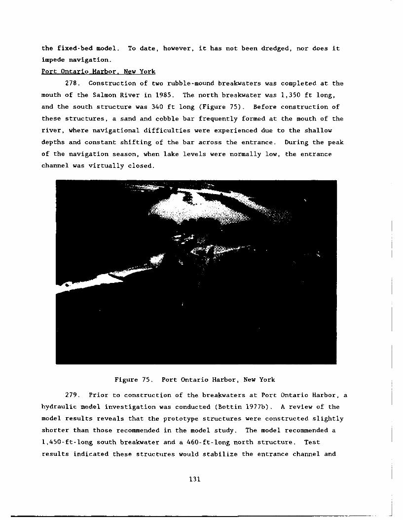
the fixed-bed model. To date, however, it has not been dredged, nor does it
impede navigation.
Port Ontario Harbor. New York
278. Construction of two rubble-mound breakwaters was completed at the
mouth of the Salmon River in 1985. The north breakwater was 1,350 ft long,
and the south structure was 340 ft long (Figure 75). Before construction of
these structures, a sand and cobble bar frequently formed at the mouth of the
river, where navigational difficulties were experienced due to the shallow
depths and constant shifting of the bar across the entrance. During the peak
of the navigation season, when lake levels were normally low, the entrance
channel was virtually closed.
Figure 75. Port Ontario Harbor, New York
279. Prior to construction of the breakwaters at Port Ontario Harbor, a
hydraulic model investigation was conducted (Bottin 1977b). A review of the
model results reveals that the prototype structures were constructed slightly
shorter than those recommended in the model study. The model recommended a
1,450-ft-long south breakwater and a 460-ft-long north structure. Test
results indicated these structures would stabilize the entrance channel and
131

provide wave protection to the lower reaches of Salmon River, without
adversely affecting the passage of river flows. The prototype south break-
water was constructed on the same alignment as the recommended south structure
tested in the model, but it terminated about 100 ft closer to shore. The
north breakwater constructed in the prototype was on the same alignment as the
model structure but was positioned south of the model breakwater location,
which resulted in its reduction in length. In general, the prototype harbor
entrance orientation was similar to that tested in the model and the width be-
tween the structures were approximately the same, however, thi- entire
entrance configuration was about 100 ft shoreward of that tested.
280. An assessment of the performance of the breakwaters at Port
Ontario since construction reveals that it is providing adequate wave protec-
tion to the lower reaches of the river as predicted. On the most part, the
entrance channel has remained stable with regard to shoaling. In 1989, how-
ever, at one point the depth in the entrance channel decreased to about 3 ft.
These depositr were believed to be from the river. Because of an extremely
dry winter, there was not enough runoff and subsequent river flow to move the
river sediment completely into the lake. A rain storm occurred and the depths
in the entrance increased from 3 ft to a range of about 7 to 9 ft (8-ft depth
authorized). With the exception of this one occurrence, the harbor entrance
has remained stable. The structures appear to be performing as predicted with
regard to the prevention of channel shoaling due to sediment moving along the
shoreline.
Oswego Harbor, New York
281. Oswego Harbor was initially developed in 1882 and consisted of a
4,515-ft-long west breakwater. A 2,700-ft-long west arrowhead and a 2,200-ft-
long east arrowhead breakwater were constructed during the period 1931 to
1932. Storm waves propagated through the 650-ft-wide entrance and caused
considerable damage to harbor facilities after breakwater construction. To
protect the navigation opening and improve wave conditions in the harbor, qn
850-ft-long detached rubble-mound breakwater (Figure 76) was completed in
1959. The detached breakwater concept was model tested prior to construction.
282. A review of the modpl test results of Oswego Harbor (Fortson
et al. 1949) indicated that the optimum improvement plan considering wave
protection and costs was a 650-ft-long detached breakwater situated 640 ft
lakeward of the existing navigation opening. Concern was expressed, however,
132
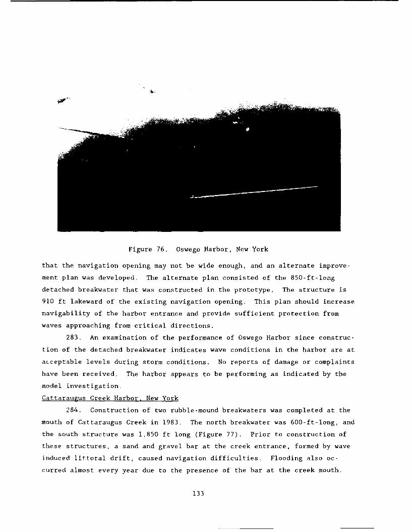
Figure 76. Oswego Harbor, New York
that the navigation opening may not be wide enough, and an alternate improve-
ment plan was developed. The alternate plan consisted of the 850-ft-long
detached breakwater that was constructed in the prototype. The structure is
910 ft lakeward of the existing navigation opening. This plan should increase
navigability of the harbor entrance and provide sufficient protection from
waves approaching from critical directions.
283. An examination of the performance of Oswego Harbor since construc-
tion of the detached breakwater indicates wave conditions in the harbor are at
acceptable levels during storm conditions. No reports of damage or complaints
have been received. The harbor appears to be performing as indicated by the
model investigation.
Cattaraugus Creek Harbor, New York
284. Construction of two rubble-mound breakwaters was completed at the
mouth of Cattaraugus Creek in 1983. The north breakwater was 600-ft-long, and
the south structure was 1,850 ft long (Figure 77). Prior to construction of
these structures, a sand and gravel bar at the creek entrance, formed by wave
induced littoral drift, caused navigation difficulties. Flooding also oc-
curred almost every year due to the presence of the bar at the creek mouth.
133

Figure 77. Cattaraugus Creek Harbor, New York
Approximately 400 small boats are permanently based in the lower reaches of
the creek.
285. Before the breakwaters were constructed, a model investigation was
conducted (Bottin and Chatham 1975). A review of the model report indicates
that the prototype structures were constructed almost the same as the recom-
mended model structures. The only difference was that the south breakwater in
the model had a dogleg, and the breakwater is curved in the prototype. The
ends of the breakwaters were in the same relative locations, and the distance
between the heads of the structures is the same as that tested in the model.
Therefore, with only the minor change in the trunk of the south breakwater,
the results obtained in the model should be applicable to the prototype. The
model predicted that the structures would stabilize the entrance channel,
provide wave protection to the lower reaches of the creek, and provide for the
satisfactory passage of flood and ice flows.
286. The Cattaraugus Creek Harbor project was selected for the MCCP
program. Extensive monitoring of the project was accomplished to determine if
the completed project performed as intended. Preparation of the report is
1334

currently in progress. The monitoring effort indicates that the model did an
excellent job in identifying the best way to eliminate shoaling in the naviga-
tion channel; preventing ice jams, recognizing the limitations of the state of
the art in modeling lake ice; and designing a channel safe for navigation in
high wave conditions. The structures provide wave protection to the lower
reaches of the creek, prevent shoaling of the entrance, and allow for the
passage of flood and ice flows as predicted by the model investigation. In
some instances lake ice has prevented river ice flows from entering the lake
and resulting in inland flooding. The use of ice breaking equipment has
helped to minimize flooding problems.
Barcelona Harbor. New York
287. Construction of a 693-ft-long east breakwater and a 790-ft-long
west breakwater was completed at Barcelona in 1960. The structures were con-
structed with cellular steel sheetpiling. A 174-ft-long steel sheet-pile
shore arm connecting the west breakwater to shore also was included. Subse-
quent to construction of the breakwaters, a vertical faced public wharf was
constructed. Wave energy propagating into the harbor and reflecting off the
wharf and vertical cellular breakwaters resulted in standing and multi-
directional waves up to 4 ft in height. In 1984, construction of a 250-ft-
long, lakeward west breakwater extension, a 150-ft-long shoreward east break-
water extension, and segmented wave absorbers adjacent to the harbor side of
the west breakwater was completed (Figure 78). The modifications were con-
structed of rubble-mound materials. The 1984 modifications were tested in a
model prior to construction.
288. A review of the model investigation of Barcelona Harbor (Bottin
1984a) indicated that the harbor modifications were constructed in the proto-
type as recommended by the model test results. The harbor revisions should
reduce wave heights in the mooring areas to 2 ft or less during periods of
storm wave activity with the exception of summer waves that have a 20-year re-
currence interval. Wave heights for 20-year summer conditions will exceed the
2-ft criterion by 0.2 to 0.3 ft for waves from the west and northeast. A
parapet wall on the west breakwater and a shoreward extension of the east
structure would achieve the desired criterion from these directions, but were
not constructed in the prototype.
289. An examination of the performance of Barcelona Harbor since con-
struction of the 1984 modifications reveals that the harbor is functioning
135

Figure 78. Barcelona Harbor, New York
well during periods of storm wave activity. After construction, in December
1985, a record storm hit the harbor. It performed well with no reports of
damage. Local harbor users are well pleased with the project. What was
almost an unusable harbor, before improvements, is now highly utilized. In
fact, the harbor is at capacity with no room for expansion. The project is
performing as predicted by the model study.
Conneaut Harbor, Ohio
290. Construction of east and west jetties was completed at the mouth
of the Conneaut River in 1894. During the period 1905 to 1936, outer east and
west breakwaters were constructed lakeward of the river mouth. Hydraulic
problems encountered at the harbor after this construction included excessive
wave heights in the outer navigation entrance, and navigational problems in
the inner entrance due to the alignment of the jetties with excessive seiche
currents across the entrance. In 1965, construction of a shore-connected east
breakwater was completed and the east jetty was realigned and shortened
(Figure 79). The 1965 improvemeints were model tested prior to construction.
291. A review of the model investigation (Hudson and Wilson 1963) indi-
cated that an extension of the east breakwater to shore would reduce currents
136

Figure 79. Conneaut Harbor, Ohio
at the entrance to the inner harbor to acceptable levels. The study also
recommended removing or shortening and realigning the east jetty parallel to
the west jetty to provide a satisfactory navigation width without permitting
increased wave action in the inner harbor. In addition, the model investiga-
tion recommended a detached 900-ft-long breakwater situated about 1,600 ft
lakeward of the outer navigation opening to provide additional wave protection
to the outer entrance and inner harbor. The east breakwater shoreward exten-
sion constructed in the prototype was the design recommended in the model. A
100-ft-wide gap between the existing breakwater and extension provided the
passage of light-draft vessels without affecting current velocities at the
inner harbor entrance. The shortening and realigning of the east pier per-
formed in the prototype also was recommended in the model to improve naviga-
bility. The offshore detached breakwater recommended in the model to reduce
wave heights in the outer entrance inner harbor, however, was not constructed
in the prototype.
292. An examination of the performance of the harbor after the 1965
improvements reveals improved navigability into the inner harbor as predicted
137

by the model study. The shoreward extension of the east breakwater eliminated
excessive currents across the entrance to the inner harbor as expected, and
shortening and realignment of the east jetty provided a satisfactory naviga-
tion width. No navigation problems have been reported since construction. An
erosion problem, however, was encountered along the shoreline east of and
adjacent to the east breakwater extension after construction of the structure.
The erosion, due to wave reflection off the vertical-wall breakwater, extends
eastward about 1,000 to 1,500 ft. The area is undeveloped and the shoreline
appears to have reached equilibrium, therefore, no remedial action has been
taken.
Geneva-on-the-Lake Small-Boat Harbor, Ohio
293. Construction of Geneva-on-the-Lake Small-Boat Harbor was completed
in 1987. Included in construction were two rubble-mound breakwaters. The
east structure was 600 ft long and the west breakwater was 850 ft long. The
structures originated as an arrowhead configuration converging toward each
other, but the outer 200 ft of the breakwaters are parallel (Figure 80).
Spurs, about 25 ft long, extend lakeward from a revetted entrance. A
Figure 80. Geneva-on-the-Lake Small-Boat Harbor,Ohio
138

revetment also extends along the west and south sides of the harbor. The
harbor was constructed to provide a small-boat harbor-of-refuge and recre-
ational facilities for boaters in the area. It borders Geneva State Park.
294. Prior to construction of the small-boat harbor, a model investiga-
tion was conducted (Bottin 1982a). A review of the model report indicates
that the harbor was constructed in accordance with recommendations of the
model investigation. Test results indicated this configuration would provide
adequate wave protection to the harbor and prevent shoaling of the entrance
channel.
295. A review of the postconstruction performance of the small-boat
harbor reveals that no complaints have been received relative to wave condi-
tions in the entrance and mooring areas and/or entrance shoaling. The proto-
type harbor is performing as predicted by the model investigation. The break-
water structures are trapping sediment moving from west to east, however, and
beach replenishment, as well as other protective measures, have been imple-
mented on the east side of the harbor. This condition was c::pe'ted since the
model study indicated no natural sand bypassing at the site.
Vermilion Harbor, Ohio
296. Construction of parallel jetties at the mouth of the Vermilion
River was completed during the period 1836 to 1839. In 1874 the east and west
jetties were extended to lengths of 458.5 ft and 1,333.5 ft, respectively.
Storm waves, however, would break inside and immediately outside the entrance
jetties, which made navigation difficult and dangerous, even during moderate
storms. In 1973, an 864-ft-long detached breakwater was completed at Vermil-
ion (Figure 81) to provide wave protection to the entrance. It was con-
structed with cellular steel sheetpiling. The offshore breakwater concept was
model tested.
297. A review of the model study report (Brasfeild 1970) revealed that
a 700-ft-long offshore breakwater situated perpendicular to the entrance chan-
nel about 200 ft from the outer end of the existing east jetty would provide
adequate wave protection. The offshore structure built in the prototype was
164 ft longer than that recommended in the model. In addition, it was located
330 ft from the lakeward end of the east jetty. The model study report did,
however, address the possibility of a longer structure placed further lakeward
to provide more navigation clearance. Even though model tests were not con-
ducted, and it could not be stated categorically, it was believed that the
139
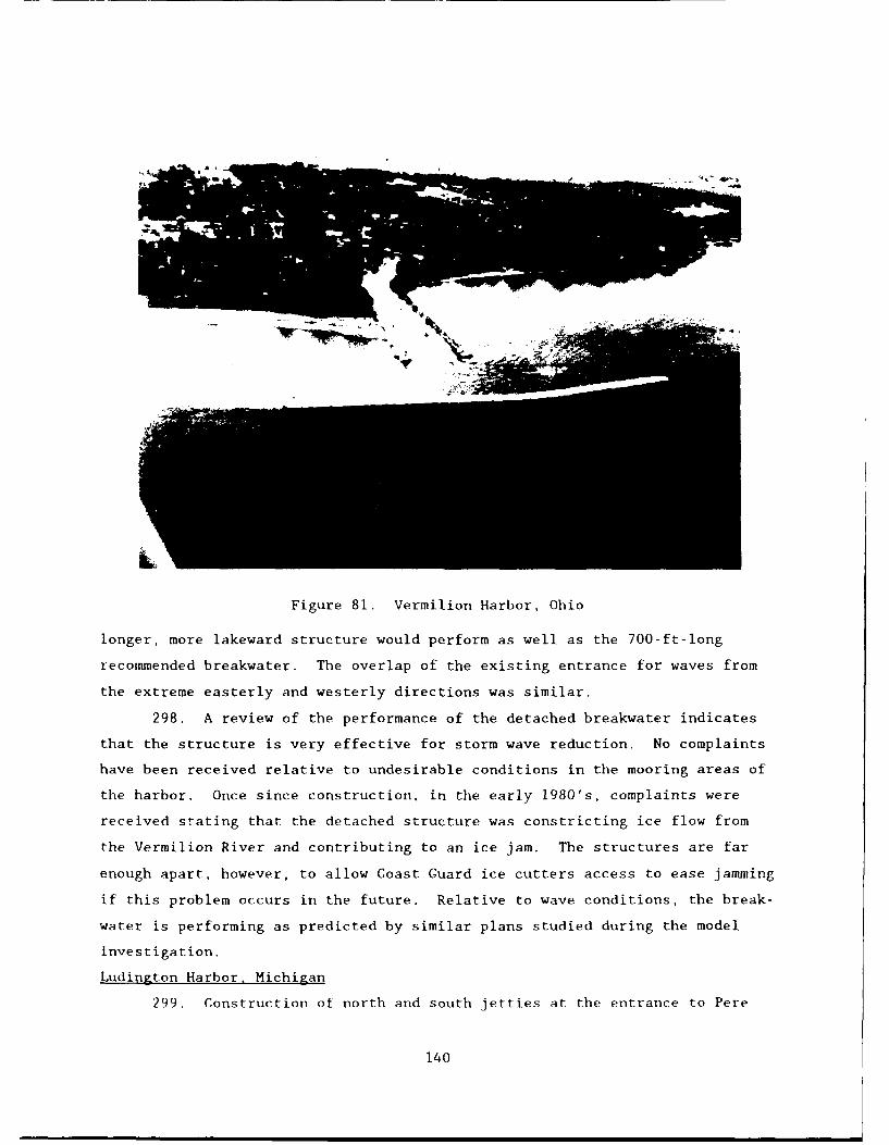
L
Figure 81. Vermilion Harbor, Ohio
longer, more lakeward structure would perform as well as the 700-ft-long
recommended breakwater. The overlap of the existing entrance for waves from
the extreme easterly and westerly directions was similar.
298. A review of the performance of the detached breakwater indicates
that the structure is very effective for storm wave reduction. No complaints
have been received relative to undesirable conditions in the mooring areas of
the harbor. Once since construction, in the early 1980's, complaints were
received stating that the detached structure was constricting ice flow from
the Vermilion River and contributing to an ice jam. The structures are far
enough apart, however, to allow Coast Guard ice cutters access to ease jamming
if this problem occurs in the future. Relative to wave conditions, the break-
water is performing as predicted by similar plans studied during the model
investigation.
Ludington Harbor. Michigan
299. Construction of north and south jetties at the entrance to Pere
140

Marquette Lake at Ludington was completed during the 1866-1874 time frame.
Later the construction of arrowhead breakwaters forming an outer harbor at the
site was completed during the 1907-1914 period (Figure 82). Periodic repairs
and maintenance have been performed on the structures since construction.
From 1977 to 1981, the south jetty was reconstructed using rubble-mound struc-
tures, and a rubble absorber was installed adjacent to the north jetty.
Several improvement plans at the inner entrance were model tested prior to the
construction.
PP
Figure 82. Ludington Harbor, Michigan
300. A review of model test results (Crosby and Chatham 1975) indicates
that a 500-ft-long rubble absorber on the south side and a 900-ft-long rubble
absorber on the north side of the channel would provide the desired level of
protection with respect to wave action in the inner harbor and navigation
conditions in the inner entrance. The lengths of the rubble absorbers in-
stalled in the prototype were 505 and 1,061 ft for the south and north
jetties, respectively.
301. A review of the improvements at Ludington Harbor as a result of
the model study reveals that the absorbers perform quite satisfactorily. Wave
141
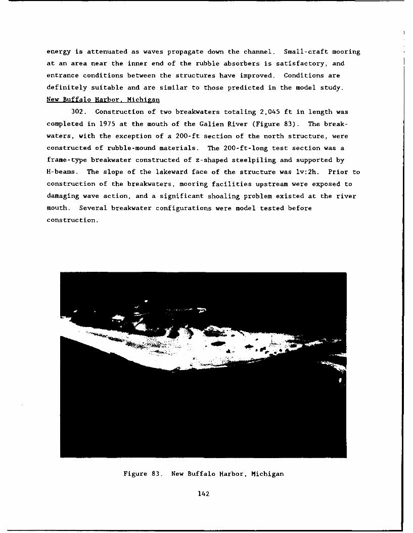
energy is attenuated as waves propagate down the channel. Small-craft mooring
at an area near the inner end of the rubble absorbers is satisfactory, and
entrance conditions between the structures have improved. Conditions are
definitely suitable and are similar to those predicted in the model study.
New Buffalo Harbor, Michigan
302. Construction of two breakwaters totaling 2,045 ft in length was
completed in 1975 at the mouth of the Galien River (Figure 83). The break-
waters, with the exception of a 200-ft section of the north structure, were
constructed of rubble-mound materials. The 200-ft-long test section was a
frame-type breakwater constructed of z-shaped steelpiling and supported by
H-beams. The slope of the lakeward face of the structure was lv:2h. Prior to
construction of the breakwaters, mooring facilities upstream were exposed to
damaging wave action, and a significant shoaling problem existed at the river
mouth. Several breakwater configurations were model tested before
construction.
44
Figure 83. New Buffalo Harbor, Michigan
142
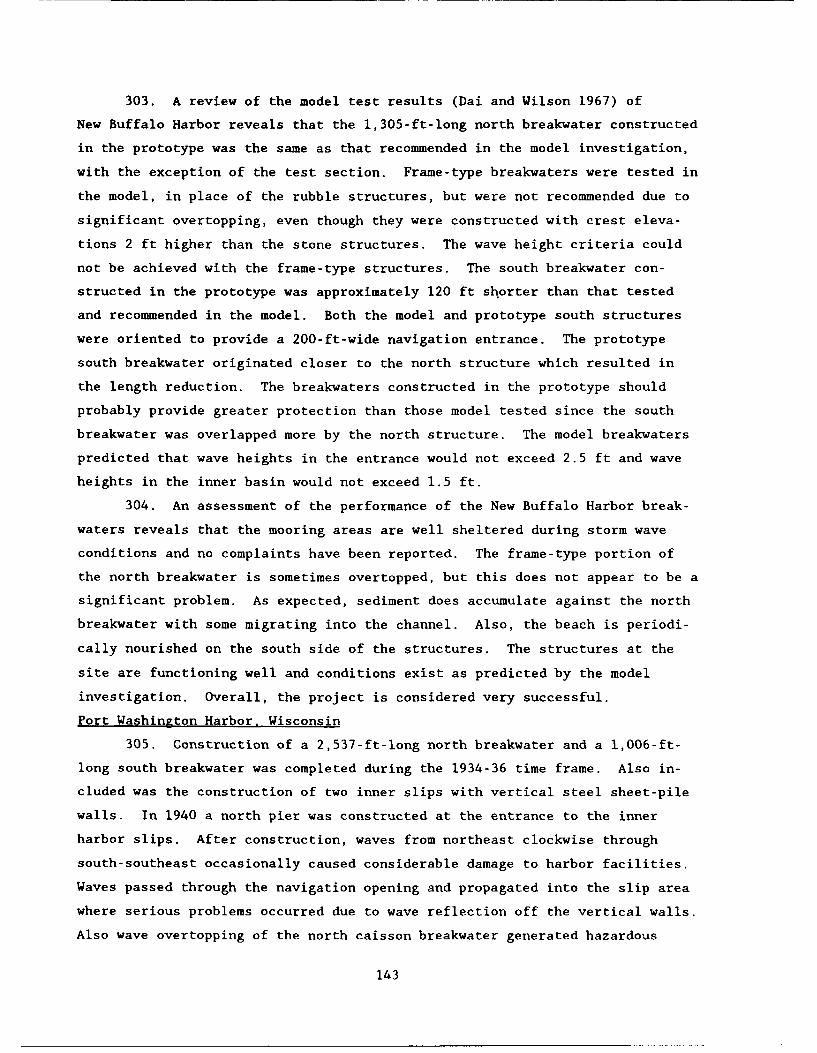
303. A review of the model test results (Dai and Wilson 1967) of
New Buffalo Harbor reveals that the 1,305-ft-long north breakwater constructed
in the prototype was the same as that recommended in the model investigation,
with the exception of the test section. Frame-type breakwaters were tested in
the model, in place of the rubble structures, but were not recommended due to
significant overtopping, even though they were constructed with crest eleva-
tions 2 ft higher than the stone structures. The wave height criteria could
not be achieved with the frame-type structures. The south breakwater con-
structed in the prototype was approximately 120 ft shorter than that tested
and recommended in the model. Both the model and prototype south structures
were oriented to provide a 200-ft-wide navigation entrance. The prototype
south breakwater originated closer to the north structure which resulted in
the length reduction. The breakwaters constructed in the prototype should
probably provide greater protection than those model tested since the south
breakwater was overlapped more by the north structure. The model breakwaters
predicted that wave heights in the entrance would not exceed 2.5 ft and wave
heights in the inner basin would not exceed 1.5 ft.
304. An assessment of the performance of the New Buffalo Harbor break-
waters reveals that the mooring areas are well sheltered during storm wave
conditions and no complaints have been reported. The frame-type portion of
the north breakwater is sometimes overtopped, but this does not appear to be a
significant problem. As expected, sediment does accumulate against the north
breakwater with some migrating into the channel. Also, the beach is periodi-
cally nourished on the south side of the structures. The structures at the
site are functioning well and conditions exist as predicted by the model
investigation. Overall, the project is considered very successful.
Port Washington Harbor. Wisconsin
305. Construction of a 2,537-ft-long north breakwater and a l,006-ft-
long south breakwater was completed during the 1934-36 time frame. Also in-
cluded was the construction of two inner slips with vertical steel sheet-pile
walls. In 1940 a north pier was constructed at the entrance to the inner
harbor slips. After construction, waves from northeast clockwise through
south-southeast occasionally caused considerable damage to harbor facilities.
Waves passed through the navigation opening and propagated into the slip area
where serious problems occurred due to wave reflection off the vertical walls.
Also wave overtopping of the north caisson breakwater generated hazardous
143
conditions in the outer harbor area. In 1982 rubble-mound breakwaters, an
absorber, and a parapet wall were conducted to develop a small-craft harbor in
the existing Port Washington outer harbor (Figure 84). Prior to construction
of the small-craft harbor, improvements were model tested.
306. A review of the model investigation of the small-boat harbor
(Bottin 1977a) revealed that the structures built in the prototype were the
same as recommended in the model investigation. Improvements consisted of a
parapet constructed on a portion of the existing north breakwater in
conjunction with an absorber installed on the shoreward side and adjacent to
that portion of the breakwater, and new east and west rubble-mound breakwaters
enclosing the new harbor. The east breakwater was attached to the existing
north breakwater and the west breakwater was detached to provide for increased
circulation in the harbor as recommended in the model study. Also recommended
in the model, and constructed in the prototype, was steel sheetpiling in the
west breakwater to make the structure impervious, thus preventing transmitted
wave energy from entering the harbor.
Figure 84. Port Washington Harbor, Wisconsin
144

307. Immediately after construction of the new small-boat harbor at
Port Washington, it was subjected to a storm and performed very well. The
Ozaukee Press published an article entitled, "The harbor is finished . . . and
it works." The article stated that . . . "foul fall weather with strong east-
northeasterly winds put Port Washington's new small-boat harbor to the test --
and it passed with flying colors. The harbor was an oasis of calm assaulted
ineffectually by rough seas on three sides. Waves crashing into the old
breakwater were robbed of their power by the new concrete parapet. The two
new overlapping stone breakwaters repelled waves coming through the wide open
outer harbor gap." The article also stated that the storm showed off the
benefits of the new small-boat harbor and was heartening news to the community
and boat owners -- the boats moored there will have a safe haven. Subsequent
storms at Port Washington Harbor have also revealed very calm conditions in
the new harbor. Since construction of the improvements, there have been no
negative reports relative to the small-boat harbor's performance, and it has
reacted as predicted in the model investigation. The harbor is filled to
capacity with small craft.
Grand Marais Harbor. Minnesota
308. Breakwaters were constructed and/or modified at the entrance to
Grand Marais Harbor intermittently between the period 1883 to 1933. After
construction of these structures, however, storm waves continued to propagate
through the entrance into the harbor and cause damage to small boats. Small
craft had to be beached to prevent damage, even for mild storms. In 1959,
construction of a 921-ft-long rubble-mound inner breakwater was completed to
provide protection for small craft in its lee (Figure 85). The inner
breakwater had been model tested.
309. A review of the model investigation of Grand Marais Harbor
(Fenwick, Arnold, Easterby 1944) indicated that the inner breakwater con-
structed in the prototype was similar to the configuration tested, but some
discrepancies did exist. The model structure entailed a 600-ft-long timber
crib breakwater that provided protection to the proposed mooring area with a
290-ft-long rubble-mound portion extending from the western end of the timber
crib at an angle to the shoreline. The model report recommended the construc-
tion of a rubble-mound structure, as opposed to the timber crib, because wave
conditions tested behind the rubble section were less confused and lower in
height. A straight 921-ft-long rubble-mound structure was constructed in the
145

SI
Figure 85. Grand Marais Harbor, Minnesota
prototype that provided protection to the mooring area and the north bank.
The lakeward end of the inner breakwater, however, terminated about 100 ft
westward of that tested in the model, not providing quite as much overlap for
the harbor facilities.
310. A review of the performance of the inner breakwater reveals that
it provides adequate wave protection to small-craft vessels and harbor facili-
ties in its lee. The breakwater does attenuate large waves that propagate
through the outer entrance. The harbor receives heavy usage and is said to be
cramped. The depths in the harbor are too deep for economical extension of
the breakwater and expansion of the small-boat harbor. Wave conditions behind
the Grand Marais Harbor inner breakwater, however, appear to be within the
range predicted by the model study for storm wave conditions.
Discussions
311. Twenty-five small-boat harbors have been constructed in the proto-
ly|p(, s5-:;e(jtent tbo being model tested at WES. All thest, harbors have been
140

reviewed to determine, first, if they were constructed as recommended in the
model investigations and, secondly, to determine if they have performed as
predicted by the model studies. The performances of the projects were ob-
tained from reliable sources, but were not detailed and indepth in most cases.
The data obtained gives an indication of how the projects have performed and
includes any problems encountered since construction.
312. Of the 25 small-boat harbors that have been constructed, nine
projects were constructed exactly as recommended in the model investigation.
An additional 10 projects were constructed with slight modifications. In some
cases, these projects consisted of structures that were curved instead of
having a dog-leg, slightly longer structures than recommended, and/or a
reorientation that would provide the same overlap and should provide equal
protection. These 10 projects appear to be providing the same relative pro-
tection to the harbor as the recommended plans developed from the model stud-
ies. The other six harbor projects were constructed with the same basic con-
figurations as recommended in the models, but they had shorter structures,
wider entrances, deeper depths, and/or may have omitted an element (or struc-
ture) of the design. Variations from the recommended design of these six
projects could reduce their functional efficiency.
313. An assessment of the performance of the prototype harbors reveals
that most perform as predicted by the model studies. Three of the projects
receive complaints of excessive wave action in the mooring area and/or at a
boat ramp. A review of the model investigations, however, indicated that the
established wave height criteria were 2.0 ft or greater at these locations for
storm wave conditions. For the more current model studies, a criteria of
1.0 ft or less is generally established. Model tests for the three studies in
question show wave heights of 1.0 to 1.6 ft during everyday wave conditions.
Model studies predicted the wave conditions correctly; it is just that the
selected wave height criteria for the studies was too high. Other projects
have performed very well during storm wave conditions. Tracer tests were
conducted in the models of several projects to qualitatively assess sediment
deposition and scour patterns. All these prototype projects have been
evaluated with regard to shoaling, and it appears they are performing as pre-
dicted by the model test results. Shoaling of the project entrances or moor-
ing areas has not occurred since construction. Structures have been con-
structed in the prototype for three tidal inlet sites that were model tested.
147

The entrance channels are stable at two of the prototype sites, but at the
other site, the channel has migrated and meandered between the jetties (causes
of the channel migration are currently under investigation). Also, the model
was a fixed-bed study, which makes it extremely difficult to predict a stable
channel. In summary, with the exception of the one tidal inlet study, the
projects constructed in the prototype, that did not vary radically from the
designs recommended for the model studies, are performing as predicted by the
model investigations.
148
PART IV: SUMMARY OF LESSONS LEARNED
314. The interaction of storm wave phenomena at harbor sites (propaga-
tion of wave energy into harbors, diffraction of energy through harbor en-
trances, reflection of energy from structures and facilities, energy reaching
inner harbor areas through waves overtopping and/or being transmitted through
protective structures, wave generated currents, and/or storm surge currents,
etc.) creates very complex hydrodynamic conditions. When river and/or tidal
currents are present, the complexity of the dynamic hydraulic system in-
creases. Also, shoals formed in the entrances may cause breaking waves or may
redirect wave energy, through wave refraction, to other areas in the harbor
(areas that generally may not experience problems). Through the use of physi-
cal modeling, many lessons have been learned, however, optimizing the design
of a project is still a difficult problem which requires the accurate use of
the best design tools available. The physical model has proven itself a reli-
able and economically justified tool.
315. The first step for successful design of a harbor project is to
define up-to-date, realistic design conditions as well as up-to-date
bathymetric and topographic data. The designer should develop a data set
defining storm wave characteristics (period, height, direction, spectral
shape, etc.) at the site. He/she should ensure that tidal conditions (tidal
heights, velocities, prism, etc.), river discharges, ice problems, predominant
direction of sediment movement, as well as volumes, long-period wave condi-
tions, and seiche activity, if applicable, are well defined or will be deter-
mined through the course of the study. Design of a project is very dependent
upon high-quality selection and definition of hydrodynamic design conditions.
The designer should also establish a reasonable performance criterion for the
project that ensures that the design will function satisfactorily relative to
the needs of local harbor users. Prototype performance of various harbors
indicates that acceptable wave height performance criterion was met at several
sites but was too high at other sites, and continual complaints by harbor
users have been received since project construction.
316. Studies have shown that it is generally desirable to prevent wave
energy from entering a harbor as opposed to attempting to dissipate the energy
once inside the harbor. Wave energy entering a harbor can be minimized by
overlapping breakwaters at the entrance, reducing the entrance width if
149
possible, constructing breakwaters that are not easily overtopped by waves,
and using impermeable breakwater cores to the extent possible to reduce wave
transmission. Offshore structures, constructed seaward of the entrance may
also be incorporated into a design. Care must be taken, however, if the har-
bor is at a river mouth. Construction of structures at the entrance opening
may contribute to flooding upstream, due to flow restriction and/or ice jam-
ming in the colder climates.
317. Physical limitations or project costs may prohibit the con-
struction of structures which will allow less wave energy into a harbor.
Studies reveal that it is very difficult to reduce wave energy once it enters
the harbor; however, measures can be taken to absorb some of his energy.
Rubble wave absorbers and/or spending beaches may be constructed at critical
locations (where wave energy is high) in the harbor and effectively absorb
energy and, thus, reduce undesirable wave effects. Also, in areas where
standing waves exist, spending beaches, rubble absorbers, and/or concrete
absorber units (i.e. such as igloos) may be effective in the reduction of wave
energy.
318. Harbor entrance channels should not be aligned parallel to incom-
ing wave crests. In this event, small craft must enter broadside to incoming
waves which is very hazardous. In areas where these conditions currently
exist, breakwater arms or extensions may be constructed seaward and parallel
to the entrance channel. This will provide a calm area in which vessels can
be controlled prior to entering the harbor.
319. Vertical-wall breakwaters and harbor structures are highly reflec-
tive and should be avoided in areas where higher levels of wave energy are
present. Waves reflected off entrance structures result in very confused and
hazardous conditions for navigation. Vertical walls inside harbors where wave
energy is present cause hazardous anchorage and mooring conditions resulting
in more frequent damage to facilities and small boats. Reflected waves from
vertical structures also induce erosion.
320. Model tests have shown that absorbers installed along the slips of
various harbors are essentially ineffective in dissipating long-period wave
energy. In harbors where the mode of oscillation of a basin is excited by the
frequencies of wave energy entering the harbor, the basins will respond and
standing waves may result which could result in damages to both moored vessels
and dock facilities. Changing the geometric configuration of the basin could
150

remedy the condition, but the new configuration may respond to anocher wave
frequency. These problems are very difficult to alleviate, however, model
testing has indicated that long-period wave energy entering a harbor may be
reduced by a structure that overlaps the entrance opening. An offshore struc-
ture seaward of the entrance also may reduce oscillations in the harbor bas-
ins. To be effective, the offshore structure needs to be relatively
impermeable.
321. Harbor facilities and/or boat ramps should not be constructed
adjacent to an entrance opening. Wave energy propagating through and dif-
fracting around entrance structures may impinge upon the facilities and cause
undesirable conditions. In areas where physical limitations exist, harbor
facilities may be protected by interior breakwater structures or revetted
moles. Prototype performance of various harbor sites has shown these improve-
ments to be very effective, however, when inner structures or moles are con-
structed, future expansion is sometimes limited. Inner breakwaters and revet-
ted moles also have been used to protect harbor facilities in the lee of
existing structures where overtopping and/or excessive wave transmission
exist. In other instances, breakwaters have been raised and sealed, or para-
pets have been installed to minimize the amount of wave energy entering the
harbor.
322. Harbor entrances should not be oriented toward the upcoast side in
which sediment is moving alongshore. In most cases, the protective structures
will serve as a trap and sediment may deposit in the entrance channel. It is
very desirable to build structures that will contribute to natural sand by-
passing of the harbor entrance. Tests have shown that structure and entrance
openings oriented toward the downcoast side of the predominant direction of
sediment movement contribute to natural bypassing. An outer curved breakwater
which overlaps a short shore-connected structure allows sediment to move
around the entrance and on downcoast. The shorter downcoast structure assists
in minimizing movement of sediment along the shoreline, due to eddies and
periods of reversal of sediment movement, and into the entrance. Prototype
performance of several harbor sites have validated the qualitative methods of
determining sediment movement used in model investigations as reliable tools.
Improvement plans were developed that would prevent shoaling in the harbor
entrances and/or mooring areas. These plans, after being constructed in the
prototype, proved very effective.
151

323. At some existing harbors, sediment moving alongshore is inter-
cepted by a structure and moves along its axis where it deposits in the
entrance channel. Model tests and prototype performance have indicated that
spurs installed adjacent to the seaward sides of the structures tend to
deflect flow (sediment) away from the entrance. Spurs, in some model tests,
also have been used to deflect undesirable crosscurrents away from harbor
entrances.
324. Model tests and subsequent prototype performance have shown that
segmented breakwaters are effective in providing wave protection while still
allowing tidal circulation through the breakwater openings. They proved more
effective than baffled breakwaters in model tests. Consideration may be given
to using segmented structures in lieu of floating or baffled breakwaters,
where both wave protection and harbor flushing is required. Segmented rubble
absorbers inside a harbor, as opposed to a continuous absorber, also have been
effective in both the model and in the prototype. This alternative may result
in significant cost savings through reduction of stone quantities.
325. Waves breaking across reefs generally result in very strong cur-
rents alongshore. These crosscurrents may be hazardous to small craft enter-
ing and navigating channels cut through the reef and into harbors. Model
tests and subsequent prototype performance have indicated that breakwaters may
be used to deflect these currents offshore away from the entrance, and thus,
alleviate or minimize hazardous crosscurrents. Circulation channels have also
been very effective in providing harbor flushing for harbors situated in reef
areas.
326. In tidal inlets, an even distribution of flow (without excessively
high or undesirably low velocities) is required. Model tests indicate that
the jetties used to stabilize the inlet should in most cases be of equal
length. They should also be parallel or dikes should be installed to divert
or concentrate the flow of tidal currents through the desired channel align-
ment and thus prevent channel meandering and possible undercutting of struc-
tural toes. The width between the jetties is important to a stable inlet and
depends upon the volume included in the tidal prism or the actual tidal flow
exchange through the inlet. Where weir sections and deposition basins are
used to trap sediment moving alongshore, it is important that location of the
weir be properly selected. The weir should also be installed low enough to
152

allow adequate velocities and sediment to move over the structure and into the
deposition basin but high enough to prevent excess wave agitation.
153

PART V: FUTURE RESEARCH ACTIVITIES RECOMMENDED
327. Complete design guidance on conditions required to provide safe
mooring in small-boat harbors has not yet been developed. For the hydraulic
model investigations conducted at WES, wave height criteria established in the
harbor mooring areas have ranged from 0.5 to 2.0 ft. The sponsor of each
model investigation tends to establish a rule-of-thumb wave height criterion
for small-boat harbor mooring. Research should be conducted to establish
Corps of Engineers design guidance on harbor mooring criteria for small-craft
vessels of various sizes (i.e. fishing craft, small commercial craft, and
recreational boats) as well as for various types of docks and mooring systems.
Prototype wave data could be obtained to determine conditions which cause
damage and/or produce problems or hazardous mooring conditions. These data,
among other considerations, could be used as a basis of establishing the
criteria.
328. Navigation of small-craft vessels through a harbor entrance in a
severe wave environment can be very hazardous; however, adequate design crite-
ria have not been established with regard to safe navigation conditions.
Entrance channel wave height criteria varied from 3 to 6 ft in hydraulic model
investigations conducted at WES. Research is needed to establish safe naviga-
tion conditions for various-size vessels and entrance types. Prototype data
should be obtained to establish what level of wave and/or current conditions
produce unsafe entrance conditions foL. various-size vessels. In addition to
wave characteristics, instrumentation could be installed on small craft to
measure vessel response when conditions are approaching an unsafe level.
Vessel response also could be determined by use of scale model small craft
with scaled wave conditions of the prototype in a physical model. Model ves-
sel response relative to a wide range of wave conditions and directions could
be defined to determine entrance channel criteria for safe navigation.
329. In many harbors, it is not feasible to construct offshore break-
waters to prevent wave energy from entering the harbor. Excessive wave energy
and/or standing waves, therefore, exist within the harbor during storm events.
Research should be conducted to determine the most effective and efficient
placement of spending beaches or wave absorbers in harbors and/or harbor bas-
ins. Slopes of the beaches and absorbers, as well as their placement, along
with development of various types of wave absorbers could be investigated in
154
physical models. Test results for rubble-wave absorbers with various slopes
and stone sizes could be compared with concrete absorber units (i.e. such as
igloos), as well as new concepts, to determine the optimum absorber design for
various design wave conditions and harbor geometries.
330. Shoaling of harbor entrances is a major problem and causes diffi-
cult and hazardous navigation conditions. In addition, expensive maintenance
dredging or artificial bypassing is required. Model tracer tests for site
specific projects have indicated that design features of the entrance struc-
tures can be improved to minimize or alleviate channel shoaling. Model tests
also have revealed that spurs installed adjacent to structures can deflect
flow (sediment) away from the entrance channel. Research should be conducted
to determine an optimum design for the layout of harbor entrance structures
with regard to channel shoaling. Based on model tests, the predominant mode
of sediment movement is in the breaker and swash zones along the shoreline.
The angle of a structure relative to the shoreline and relative the angle of
wave approach at the structure appears to be critical. It has been noted that
reflections from some structures prevent sediment accumulations in the en-
trance channel. The angle of deflection of longshore currents by structures,
or spurs, also appears, in some cases, to deflect sediments into deeper water
seaward of the breaker zone. Research also should be conducted to determine
an optimum design for the natural bypassing of sediments around harbor
entrances.
331. Many harbors that provide adequate storm wave protection experi-
ence problems with harbor circulation or flushing. Stagnation causes unde-
sirable water quality. Research should be conducted to improve and/or develop
methods for providing improved harbor flushing. The proper placement of
structures that would redirect wave-generated currents and/or tidal currents
should be studied. Also, the effectiveness of circulation channels and/or
gaps in breakwater structures or baffled and segmented structures, that would
provide for circulation and not increase wave conditions in the harbor, should
be examined.
332. Many harbors on the ocean coasts experience long-period wave prob-
lems which result in significant horizontal water movements in nodal areas and
vertical motions at antinodes of the oscillation. This occurs when the mode
of oscillation of the harbor basin is excited by frequencies of incident wave
energy entering the harbor. Vessels and harbor facilities are frequently
155

damaged when these conditions occur. Minor structural modifications are inef-
fective in alleviating these undesirable conditions. Research should be con-
ducted to determine the most effective solution to this problem. For some
cases that have been model tested, relatively impervious structures seaward of
the entrance show some promise in reducing this wave energy. This alternative
should be subjected to more extensive testing. In addition, other alterna-
tives should be examined. Changes in geometric shapes of harbors (i.e.
rounded basins versus rectangular basins) and the installation of flat slopes
and/or solid barriers in harbor basins to change the oscillations patterns
should be investigated.
333. Numerous problems occur in tidal inlets along the coasts of the
United States and it territories. The interaction of wave-induced currents
and tidal currents, sometimes with freshwater discharges, through an inlet
connecting the ocean with an embayment is very complex. Extensive dredging is
required to maintain adequate depths in navigation channels, and maintenance
of jetties at inlet openings can be a serious problem due to continued scour
and undermining of structures. An undistorted physical inlet model should be
constructed and tested with a range of wave conditions superimposed on simu-
lated tidal conditions. Waves and currents throughout the inlet could be
quantified and a better understanding of the fundamental hydrodynamic pro-
cesses could be realized. Tracer tests could be conducted in the inlet to
give qualitative indicators of sediment patterns resulting from wave-current
interactions. Research then could be conducted with movable-bed areas in an
effort to quantify sediment movement as a result of various test conditions.
After the fundamental processes are better understood, research should be
conducted to develop methods to better stabilize inlet openings, minimize
shoaling, and reduce maintenance costs.
156
PART VI: PHYSICAL MODELING GUIDELINES
334. This part of the report provides guidelines tbit designers of
small-boat harbors can use to determine when and what type physical model
investigation can be used to enhance and optimize the project design. Small-
boat harbor models, in general, are discussed as well as design information
required for a physical model investigation.
Small-Scale Harbor Models
335. Three-dimensional harbor wave action model studies have been con-
ducted at WES since the 1940's. The hydraulic scale model is commonly used as
a design tool to aid in the planning of harbor development and in the design
and layout of breakwaters, jetties, groins, absorbers, etc. to obtain optimum
harbor protection and verify and/or define suitable project performance.
Modeling techniques and procedures as well as methods of data collection have
been maintained at the leading edge of technology, and reproduction in the
model of very complicated hydrodynamic phenomena has become possible through
experience gained during the conduct of reimbursible work and basic and ap-
plied research. The small-scale physical hydraulic model is the most reliable
means of determining an optimum plan for harbor or inlet improvements, parti-
cularly when short-period wave effects are prevalent. The model can reproduce
breaking waves, wave-current interactions, and the simultaneous effects of
wave refraction, diffraction, overtopping, transmission, and reflection.
336. Small-boat harbor design is very difficult due to the complexity
of hydrodynamics and geometry of most harbors. Physical hydraulic models
generally are used to:
a. Determine the optimum location, alignment, height, length, andtype of breakwaters required to provide adequate wave protec-tion in harbor mooring areas and entrance channels and toquantify wave and current characteristics.
b. Determine the location, alignment, and composition of spendingbeaches and/or other energy dissipating structures inside theharbor area. These may be rubble-wave absorbers or concreteabsorber units.
c. Determine the optimum length and/or alignment of breakwater orjetty structures required to minimize shoaling in harbor en-trance channels. Information on the effects of structures on
157

the littoral processes can be gained through the use of modeltracer materials.
d. Determine the optimum length and/or alignment of breakwaters,jetties, or spurs required to alleviate undesirable wave-induced crosscurrents and/or shoaling in harbor entrance chan-nels. Plans to provide for increase wave-induced harbor cir-culation and/or flushing also may be optimized through studiesand quantification of current velocities developed by variousdesign alternatives.
e. Determine the response of various harbor configurations orexpansions to long-period wave energy incident to the site.Nodal and antinodal areas may be identified in the harbor forvarious frequencies and the water velocities and water surfacemotions can be quantified at these locations.
f. Determine river flood and/or ice flow conditions that may en-ter in or adjacent to a harbor, and quantify the impact ofthat structural modification at the harbor will have on theseconditions. In addition, qualitative information on bed loadriver sediment movement may be defined.
&. Study and quantify the effects of harbor modifications onthermal stratification through the use of heated and dyedwater input at designated locations.
h. Determine tidal currents or seiche generated currents in aharbor or its entrance. Tidal currents through an inlet en-trance may be studied and quantified to determine the optimumplacement of structures required to stabilize the inlet andminimize maintenance dredging.
337. During the conduct of model investigations, remedial plans are
developed, as needed, to alleviate undesirable conditions that may exist.
Design modifications also are tested, if feasible, in an effort to reduce
construction costs and still provide highly functional harbor designs.
Design Information Required for Model Investigations
338. It is very important to determine realistic and accurate design
conditions when developing a hydraulic model investigation. The designer
should be sure deepwater wave characteristics (period, height, direction,
spectral shape, recurrence intervals, etc.) have been well defined (measured
or hindcast) offshore of the site. On the open coast, a wave refraction
analysis should be conducted. When waves move into water of gradually
decreasing depth, transformations take place in all wave characteristics
158

except wave period (to the first order of approximation). The most important
are the changes in wave height and direction of travel. Wave refraction and
shoaling coefficients are determined from deep water to the depth of water
simulated at the wave generator in the model. The bathymetry from the wave
generator to the harbor site will correctly refract and shoal the waves as
they propagate over the model. Measured prototype wave data and/or hindcast
data are obtained for the site to determine wave characteristics and recur-
rence intervals, or return periods, needed for the investigation.
339. To ensure proper wave transformation to the harbor site it is
important that current and accurate bathymetric data is provided. The more
detailed the data, the more accurate the model can be constructed. Shoreline
details, irregularities, and overbank elevations also are important so that
correct overtopping, runup, and reflective characteristics are simulated.
340. If existing breakwaters, revetments, groins, absorbers, or other
structures are present, detailed, as-built data is needed on structure cross-
sections, lengths, and alignments. Depending on the required model scale,
adjustments are made to sizing of model construction material to ensure that
correct wave transmission, overtopping, and reflection characteristics are
reproduced in the model.
341. Still-water levels also are important design conditions. They are
selected so that wave-induced phenomena dependent on water depths are accu-
rately reproduced in the model. Normally, more wave energy reaches a harbor
site during periods when higher water stages occur in the prototype. These
may be during the higher water phase of the local tidal cycle or higher lake
levels due to seasonal fluctuations. Also, most storms moving onshore are
characteristically accompanied by a higher water level due to wind tide and
shoreward mass transport. Conversely, however, lower water levels may result
in further offshore movement of longshore sediment (i.e. around the head of a
jetty into an entrance channel) since the breaker zone is further offshore
with lower swl's. Prior to the conduct of a model investigation critical
swl's must be defined.
342. If sediment movement alongshore is a concern at a harbor site, the
design engineer should make ,ure that the direction of predominant sediment
movement is determined prior to a model investigation. The design engineer
also should determine if reversals are probable at the site. Model tests can
be performed to qualitatively determine sediment movement patterns and likely
159
areas of accretion or shoaling. To deter.nine the tracer material to be used,
the median diameter (D5 0 ) of the prototype sediment as well as its specific
gravity is required. Observations or an understanding of prototype movement
patterns is critical to initial validation of the model. Then, tracer mate-
rial can be used in concert with incident wave climates to give qualitative
indications of scour and accretion patterns and directions of predominant
sediment transport.
343. In areas where harbors are constructed in river mouths and a model
study is being developed, river discharge information will be required to
determine the impact that any harbor modification may have on river flow char-
acteristics. A range of river discharges for various return periods should be
tested. In addition, roughness coefficients (Manning's n values) must be
determined so that correct riverbed roughness and overbank roughness is simu-
lated in the model. From these values, roughness can be applied to the model
bed to simulate realistic conditions. Qualitative data on bed-load sediment
movement patterns in rivers can be determined in the model. The specific
gravity and median diameter (D50 ) of river sediments must be determined prior
to conduct of the model study.
344. In areas, such as inlets, where ebb and flood tidal currents in
conjunction with wave energy can move sediment into a navigation opening or
cause meandering of a navigation channel, tidal information will be required
prior to a model investigation. Normally, prototype data are obtained over a
representative tidal cycle to be uied as input in the model study. Tidal
elevations, tidal currents, and salinity data are generally secured during
these periods. In some model investigations, the entire tidal cycle is repro-
duced, and in others, simulation of maximum flood and ebb tidal currents are
all that are deemed necessary. Investigations reproducing the tidal cycle are
difficult and time consuming to conduct but yield very valuable information
concerning the site hydrodynamics. Generally, extensive model validation
tests are required prior to conducting tests to determine the impacts of
various improvement plans.
345. Once design conditions have been established, the model sponsor
must ensure that realistic performance requirements are established against
which improvement plans are judged as functionally acceptable. Performance of
some of the prototype harbors in which model studies have been conducted indi-
cates that the models accurately predicted wave conditions, but the wave
160

height acceptance criterion selected were excessive. This, in turn, results
in many complaints by local harbor users that excessive wave conditions are
occurring in the prototype. And this in turn incorrectly implies that the
model did not accurately define expected wave conditions in the harbor.
346. This part of the report generally discusses model investigations
and design information required for small-boat harbor studies. Although
small-boat harbors may be classified in various classification schemes, each
and every harbor is different. Each harbor has a different configuration as
well as possible different potential problems and design conditions. The
information contained herein is valid in general. For clarification on any
aspect of small-boat harbor modeling, design conditions required for modeling,
or site specific design problems, WES engineers and scientists should be
contacted for assistance and guidance.
161

REFERENCES
Ball, J. W., and Brasfeild, C. W. 1969. "Wave Action in Mission Bay Harbor,California; Hydraulic Model Investigation," Technical Report H-69-8, US ArmyEngineer Waterways Experiment Station, Vicksburg, MS.
Bolin, B. F. 1940. "Model Study of Locations for a Proposed Breakwater inSan Juan Harbor, Puerto Rico," Technical Memorandum No. 173-1, US ArmyEngineer Waterways Experiment Station, Vicksburg, MS.
Bottin, R. R., Jr. 1976. "Igloo Wave Absorber Tests for Port WashingtonHarbor, Wisconsin; Hydraulic Model Investigation," Miscellaneous Paper H-76-22, US Army Engineer Waterways Experiment Station, Vicksburg, MS.
_ 1977a. "Design for Small-Boat Harbor Improvements, Port Wash-ington Harbor, Wisconsin; Hydraulic Model Investigation," Technical ReportH-77-1, US Army Engineer Waterways Experiment Station, Vicksburg, MS.
_ 1977b. "Port Ontario Harbor, New York, Design for Wave Protec-tion and Prevention of Shoaling; Hydraulic Model Investigation," TechnicalReport H-77-20, US Army Engineer Waterways Experiment Station, Vicksburg MS.
. 1978. "Design for Harbor Entrance Improvements, Wells Harbor,Maine; Hydraulic Model Investigation," Technical Report H-78-18, US Army Engi-neer Waterways Experiment Station, Vicksburg, MS.
_ 1981. "Siuslaw River Jetty Extension Study," Letter Report,US Army Engineer Waterways Experiment Station, Vicksburg, MS.
_ 1982a. "Design for Wave Protection and Prevention of Shoaling,Geneva-on-the-Lake Small-Boat Harbor, Ohio; Hydraulic Model Investigation,"Technical Report HL-82-17, US Army Engineer Waterways Experiment Station,Vicksburg, MS.
_ 1982b. "Design for Flood Control, Wave Protection, and Preven-tion of Shoaling, Rogue River, Oregon; Hydraulic Model Investigation," Techni-cal Report HL-82-18, US Army Engineer Waterways Experiment Station, Vicksburg,MS.
1983. "Design for Flood Control, Wave Protection, and Preventionof Shoaling, Rogue River, Oregon, Appendix B: Results of Additional Tests;Hydraulic Model Investigation," Technical Report HL-82-18, US Army EngineerWaterways Experiment Station, Vicksburg, MS.
_ 1984a. "Barcelona Harbor, New York, Design for Harbor Improve-ments; Hydraulic Model Investigation," Technical Report CERC-84-3, US ArmyEngineer Waterways Experiment Station, Vicksburg, MS.
_ 1984b. "Impact of 1-644 Bridge/Tunnel Project on Wave Conditionsat Newport News Harbor, Virginia; Hydraulic Model Investigation," TechnicalReport CERC-84-4, US Army Engineer Waterways Experiment Station, Vicksburg,MS.
162
Bottin, R. R., Jr. 1990. "Current and Temperature Effects at EighteenmileCreek as a Result of Harbor Improvements at Olcott Harbor, New York; HydraulicModel Investigation," Technical Report CERC-90-3, US Army Engineer WaterwaysExperiment Station, Vicksburg, MS.
. 1991. "Ventura Harbor, California, Design for Wave and ShoalingProtection; Coastal Model Investigation," Technical Report CERC-91-3, US ArmyEngineer Waterways Experiment Station, Vicksburg, MS.
Bottin, R. R., Jr., and Acuff, H. F. 1983. "Edgewater Marina, Cleveland,Ohio, Design for Wave Protection; Hydraulic Model Investigation," TechnicalReport HL-83-11, US Army Engineer Waterways Experiment Station, Vicksburg, MS.
. 1985. "Mission Bay Harbor, San Diego County, California, Designfor Wave and Surge Protection; Coastal Model Investigation," Technical ReportCERC-85-11, US Army Engineer Waterways Experiment Station, Vicksburg, MS.
_ 1989. "Bolsa Bay, California, Proposed Ocean Entrance SystemsStudy, Report 4, Physical Model," Miscellaneous Paper CERC-89-17, US ArmyEngineer Waterways Experiment Station, Vicksburg, MS.
_ 1990. "Olcott Harbor, New York, Design for Harbor Improvements;Coastal Model Investigation," Technical Report CERC-90-1, US Army EngineerWaterways Experiment Station, Vicksburg, MS.
Bottin, R. R., Jr., Acuff, H. F., and Markle, D. G. 1988. "Noyo River andHarbor, California, Design for Wave and Surge Protection; Coastal Model Inves-tigation," Technical Report CERC-88-15, US Army Engineer Waterways ExperimentStation, Vicksburg, MS.
Bottin, R. R., Jr., and Chatham, C. E., Jr. 1975. "Design for Wave Protec-tion, Flood Control, and Prevention of Shoaling, Cattaraugus Creek Harbor, NewYork; Hydraulic Model Investigation," Technical Report H-75-18, US ArmyEngineer Waterways Experiment Station, Vicksburg, MS.
Bottin, R. R., Jr., Chatham, C. E., Jr., and Carver, R. D. 1976. "WaianaeSmall-Boat Harbor, Oahu, Hawaii, Design for Wave Protection; Hydraulic ModelInvestigation," Technical Report H-76-8, US Army Engineer Waterways ExperimentStation, Vicksburg, MS.
Bottin, R. R., Jr., and Kent, R. E. 1990. "Redondo Beach King Harbor, Cali-fornia, Development of Design Data for Harbor Improvements; Coastal ModelInvestigation," Technical Report CERC-90-6, US Army Engineer WaterwaysExperiment Station, Vicksburg, MS.
Bottin, R. R., Jr., Markle, D. G., and Mize, M. G. 1987. "Design for Naviga-tion Improvements, Wave Protection, and Breakwater Stability for ProposedBoat-Launching Facility; Laupahoehoe Point, Hawaii; Coastal ModelInvestigation," Technical Report CERC-87-3, US Army Engineer WaterwaysExperiment Station, Vicksburg, MS.
163
Bottin, R. R., Jr. and Mize, M. G. 1988. "St. Paul Harbor, St. Paul Island,Alaska, Design for Wave and Shoaling Protection, Hydraulic ModelInvestigation," Technical Report CERC-88-13, US Army Engineer WaterwaysExperiment Station, Vicksburg, MS.
_ 1989. "Noyo River and Harbor, California, Design for Wave Pro-tection, Supplemental Tests; Coastal Model Investigation," Technical ReportCERC-89-18, US Army Engineer Waterways Experiment Station, Vicksburg, MS.
_ 1990. "Redondo Beach King Harbor, California, Design for WaveProtection; Coastal Model Investigation," Technical Report CERC-90-4, US ArmyEngineer Waterways Experiment Station, Vicksburg, MS.
Bottin, R. R., Jr., Outlaw, D. G., and Seabergh, W. C. 1985. "Effects ofProposed Harbor Modifications on Wave Conditions, Harbor Resonance, and TidalCirculation at Fish Harbor, Los Angeles, California; Physical and NumericalModel Investigations," Technical Report CERC-85-2, US Army Engineer WaterwaysExperiment Station, Vicksburg, MS.
Bottin, R. R., Jr., Sargent, F. E., and Mize, M. G. 1985. "Fisherman's WharfArea, San Francisco Bay, California, Design for Wave Protection; Physical andNumerical Model Investigation," Technical Report CERC-85-7, US Army EngineerWaterways Experiment Station, Vicksburg, MS.
Brasfeild, C. W. 1965a. "Selection of Optimum Plan for Reduction of WaveAction in Marina Del Ray, Venice, California; Hydraulic Model Investigation,"Technical Report No.2-671, US Army Engineer Waterways Experiment Station,Vicksburg, MS.
_ 1965b. "Selection of Optimum Plan for Improvements in NassauHarbor, Nassau, New Providence, Bahamas; Hydraulic Model Investigation," Tech-nical Report No. 2-696, US Army Engineer Waterways Experiment Station, Vicks-burg, MS.
1970. "Wave Action and Breakwater Location, Vermilion Harbor,Ohio; Hydraulic Model Investigation," Technical Report H-70-5, US Army Engi-neer Waterways Experiment Station, Vicksburg, MS.
_ . 1973. "Wave Action and Breakwater Design, Hamlin Beach Harbor,New York; Hydraulic Model Investigation," Technical Report H-73-13, US ArmyEngineer Waterways Experiment Station, Vicksburg, MS.
Brasfeild, C. W. and Ball, J. W. 1967. "Expansion of Santa Barbara Harbor,California; Hydraulic Model Investigation," Technical Report No. 2-805,US Army Engineer Waterways Experiment Station, Vicksburg, MS.
Brasfeild, C. W., and Chatham, C. E., Jr. 1967a. "Magic Island Complex, In-cluding Kewalo Basin and Ala Wai Boat Harbor, Honolulu, Oahu, Hawaii; Hydrau-lic Model Investigation," Technical Report No. 2-767, US Army EngineerWaterways Experiment Station, Vicksburg, MS.
_ 1967b. "Expansion and Revision of Kawaihae Harbor, Hawaii; Hy-draulic Model Investigation," Technical Report No. 2-806, US Army EngineerWaterways Experiment Station, Vicksburg, MS.
164

Chatham, C. E., Jr. 1968. "Wave and Surge Conditions After Proposed Expan-sion of Monterey Harbor, Monterey, California; Hydraulic Model Investigation,"Technical Report H-68-9, US Army Engineer Waterways Experiment Station, CE,Vicksburg, MS.
. 1970. "Design for Flood Control and Wave Protection, ChagrinRiver, Eastlake, Ohio; Hydraulic Model Investigation," Technical Report H-70-11, US Army Engineer Waterways Experiment Station, Vicksburg, MS.
. 1975. "Design of Agana Small-Boat Harbor, Territory of Guam;Hydraulic Model Investigation," Technical Report H-75-1, US Army EngineerWaterways Experiment Station, Vicksburg, MS.
Chatham, C. E., Jr., and Brasfeild, C. W. 1969. "Design for Expansion ofPort San Luis, California; Hydraulic Model Investigation," Technical ReportH-69-6, US Army Engineer Waterways Experiment Station, Vicksburg, MS.
Crosby, L. G. 1974. "Design of an Interisland Barge Harbor for the Island ofTau, American Samoa; Hydraulic Model Investigation," Technical Report H-74-16,US Army Engineer Waterways Experiment Station, Vicksburg, MS.
Crosby, L. G., and Chatham, C. E., Jr. 1975. "Design of Entrance ChannelImprovements for Ludington Harbor, Michigan; Hydraulic Model Investigation,"Technical Report H-75-14, US Army Engineer Waterways Experiment Station,Vicksburg, MS.
Crosby, L. C., Durham, D. L., and Chatham, C. E., Jr. 1975. "Expansion ofPort Hueneme, California; Hydraulic Model Investigation," Technical ReportH-75-8, US Army Engineer Waterways Experiment Station, Vicksburg, MS.
Curren, C. R. 1983. "Mission Bay Harbor, California, Design for Wave andSurge Protection and Flood Control; Hydraulic Model Investigation," TechnicalReport HL-83-17, US Army Engineer Waterways Experiment Station, Vicksburg, MS.
Curren, C. R., and Chatham, C. E., Jr. 1979. "Newburyport Harbor, Massachu-setts, Design for Wave Protection and Erosion Control," Technical Report HL-79-1, US Army Engineer Waterways Experiment Station, Vicksburg, MS.
. 1980. "Oceanside Harbor and Beach, California, Design of Struc-tures for Harbor Improvement and Beach Erosion Control; Hydraulic Model Inves-tigation," Technical Report HL-80-10, US Army Engineer Waterways ExperimentStation, Vicksburg, MS.
Dai, Y. B., and Wilson, H. B. 1967. "Selection of Optimum Alignment, Length,and Height of Breakwaters, New Buffalo Harbor, Michigan; Hydraulic Model In-vestigation," Technical Report No. 2-761, US Army Engineer WaterwaysExperiment Station, Vicksburg, MS.
Fenwick, G. B., Arnold, J. C., and Easterby, J. F. 1944. "Model Study ofPlans for Reduction of Wave Action in Grand Marais Harbor, Minnesota; SecondPhase," Technical Memorandum No. 186-2, US Army Engineer Waterways ExperimentStation, Vicksburg, MS.
165
Fortson, E. P., Jr., Brown, F. R., Hudson, R. Y., and Wilson, H. B. 1949."Wave Action and Breakwater Location, Oswego Harbor, New York; Model Investi-gation," Technical Memorandum No. 2-291, US Army Engineer Waterways ExperimentStation, Vicksburg, MS.
. 1951. "Wave Action and Breakwater Location, Port WashingtonHarbor, Wisconsin; Model Investigation," Technical Memorandum No. 2-334,US Army Engineer Waterways Experiment Station, Vicksburg, MS.
Giles, M. L. 1975. "Wave and Current Conditions for Various Modifications ofKewalo Basin, Honolulu, Oahu, Hawaii; Hydraulic Model Investigation,`zTechnical Report H-75-15, US Army Engineer Waterways Experiment Station,Vicksburg, MS.
Giles, M. L., and Chatham, C. E., Jr. 1974. "Remedial Plans for Preventionof Harbor Shoaling, Port Orford, Oregon; Hydraulic Model Investigation," Tech-nical Report H-74-4, US Army Engineer Waterways Experiment Station, Vicksburg,MS.
Hollyfield, N. W., McCoy, J. W., and Seabergh, W. C. 1983. "FunctionalDesign of Control Structures for Oregon Inlet, North Carolina; Hydraulic ModelInvestigation," Technical Report HL-83-10, US Army Engineer Waterways Experi-ment Station, Vicksburg, MS.
Housley, J. G. 1959. "Location and Design of Wave Absorber, Gary Harbor,Indiana; Hydraulic Model Investigation," Technical Report No. 2-509, US ArmyEngineer Waterways Experiment Station, Vicksburg, MS.
Hudson, R. Y., and Wilson, H. B. 1963. "Improvement of Navigation Condi-tions, Conneaut Harbor, Ohio; Hydraulic Model Investigation," Technical ReportNo. 2-617, US Army Engineer Waterways Experiment Station, Vicksburg, MS.
Hughes, S. A., and Fowler, J. E. 1990. "Midscale Physical Model Validationfor Scour at Coastal Structures," Technical Report CERC-90-8, US Army EngineerWaterways Experiment Station, Vicksburg, MS.
Jackson, R. A., Hudson, R. Y., and Housley, J. G. 1959. "Wave Action andBreakwater Location, Harbor-of-Refuge for Light Draft Vessels, Barcelona,New York; Hydraulic Model Investigation," Technical Report No. 2-523, US ArmyEngineer Waterways Experiment Station, Vicksburg, MS.
McNair, E. C., and Hill, T. C. 1972. "Summary Report; Model Studies ofShrewsbury Inlet," Miscellaneous Paper H-72-2, US Army Engineer WaterwaysExperiment Station, Vicksburg, MS.
Noda, E. K. 1972. "Equilibrium Beach Profile Scale-Model Relationship,"Journal, Waterways, Harbors, and Coastal Engineering Division, AmericanSociety Civil Engineers, New York, NY, Vol 98, No. WW4, pp 511-528.
Perry, F. C., Seabergh, W. C., and Lane, E. F. 1978. "Improvements forMurrells Inlet, South Carolina; Hydraulic Model Investigation," TechnicalReport H-78-4, US Army Engineer Waterways Experiment Station, Vicksburg, MS.
166

Sager, R. A., and Hollyfield, N. W. 1974. "Navigation Channel Improvements,Barnegat Inlet, New Jersey; Hydraulic Model Investigation," Technical ReportH-74-1, US Army Engineer Waterways Experiment Station, Vicksburg, MS.
Schroeder, E. G., Jr. and Easterby, J. F. 1941. "Model Study of Plans forReduction of Wave Action in Grand Marais Harbor, Minnesota," Technical Memo-randum No. 186-1, US Army Engineer Waterways Experiment Station, Vicksburg,MS.
Seabergh, W. C. 1976. "Improvements for Masonboro Inlet, North Carolina;Hydraulic Model Investigation," Technical Report H-76-4, US Army EngineerWaterways Experiment Station, Vicksburg, MS.
Seabergh, W. C., and Lane, E. F. 1977. "Improvements for Little River Inlet,South Carolina; Hydraulic Model Investigation," Technical Report H-77-21,US Army Engineer Waterways Experiment Station, Vicksburg, MS.
Seabergh, W. C., and McCoy, J. W. 1982. "Prevention of Shoaling at LittleLake Harbor, Michigan; Hydraulic Model Investigation," Technical Report HL-82-16, US Army Engineer Waterways Experiment Station, Vicksburg, MS.
Senter, P. K., and Brasfeild, C. W. 1968. "Design for Optimum Wave Condi-tions, Crescent City Harbor, Crescent City, California; Hydraulic Model Inves-tigation," Technical Report H-68-6, US Army Engineer Waterways ExperimentStation, Vicksburg, MS.
Stevens, J. C., Bardsley, C. E., Lane, E. W., Straub, L. G., Wright,Chilton A., Tiffany, Joseph B., and Warnock, Jacob E. 1942. "HydraulicModels," Manuals of Engineering Practice, No. 25, American Society of CivilEngineers, New York, NY.
Wilson, H. B. 1965. "Wave Action and Breakwater Location, Half Moon Bay Har-bor, Half Moon Bay, California; Hydraulic Model Investigation," TechnicalReport No. 2-688, US Army Engineer Waterways Experiment Station, Vicksburg,MS.
1966. "Design for Optimum Wave Conditions, Dana Point Harbor,Dana Point, California; Hydraulic Model Investigation," Technical Report No.2-724, US Army Engineer Waterways Experiment Station, Vicksburg, MS.
. 1967. "Wave Action and Breakwater Location, Noyo Harbor, Cali-fornia; Hydraulic Model Investigation," Technical Report No. 2-799, US ArmyEngineer Waterways Experiment Station, Vicksburg, MS.
167

Waterways Experiment Station Cataloging-in-Publlcation Data
Bottin, Robert R.Physical modeling of small-boat harbors: design experience, lessons
learned, and modeling guidelines / by Robert R. Bottin, Jr., Coastal Engi-neering Research Center ; prepared for Department of the Army, U.S.Army Corps of Engineers.
170 p. : ill. ; 28 cm. - (Technical report ; CERC-92-12)Includes bibliographic references.1. Harbors - Design and construction - Models. 2. Harbors - Hy-
drodynamics - Models. 3. Hydraulic models. I. United States. Army.Corps of Engineers. I1. Coastal Engineering Research Center (U.S.)Ill. U.S. Army Engineer Waterways Experiment Station. IV. Title. V. Se-ries: Technical report (U.S. Army Engineer Waterways Experiment Sta-tion) ; CERC-92-12.TA7 W34m no.CERC-92-12