
Physical configuration and performance modeling of all-dielectric metamaterials
11
Physical configuration and performance modeling of all-dielectric metamaterials Akram Ahmadi and Hossein Mosallaei* Applied Electromagnetics Lab., ECE Department, Northeastern University, Boston, Massachusetts 02115, USA Received 17 April 2007; revised manuscript received 20 September 2007; published 4 January 2008 In this paper, physical concept and performance analysis of all-dielectric metamaterials are presented. Metamaterials with desired material parameters ± ,± are developed by creating electric and magnetic resonant modes. Dielectric disk and spherical particle resonators are considered as the great candidates for establishing the dipole moments metamaterial alphabet. A full wave finite difference time domain technique is applied to comprehensively obtain the physical insights of dielectric resonators. Near-field patterns are plotted to illustrate the development of electric and magnetic dipole fields. Geometric-polarization control of the dipole moments allows and to be tailored to the application of interest. All-dielectric double negative metamaterials are designed. Engineering concerns, such as loss reduction and bandwidth enhancement are investigated. DOI: 10.1103/PhysRevB.77.045104 PACS numbers: 42.70.Qs, 94.20.ws I. INTRODUCTION Metamaterials are receiving increasing attention in the scientific community in recent years due to their exciting physical properties and novel potential applications. 1–5 To achieve a metamaterial with a desired figure of merit, it is required to first create appropriate electric and magnetic di- pole moments in small-size scales utilizing available mate- rials and then tailor their arrangement to the application of interest. Basically, the electric and magnetic dipole moments can be envisioned as the alphabet for making metamaterials. For instance, to achieve an artificial magnetism, the most conventional approach is to implement metallic loops offer- ing magnetic dipole moments. 6 Conductor rods can be used for producing electric dipole moments. 7 Arrangements of these dipole moments can establish required material param- eters, for instance, a double negative DNG metamaterial behavior as depicted in Fig. 1. Most of the metamaterial designs are constructed with the use of metallic elements. The major drawbacks in using me- tallic inclusions are their conduction loss and fabrication dif- ficulties, especially in the optical frequencies. In addition, they show very narrow bandwidth resonant modes. Further, most of the known realizations are highly anisotropic com- posites. Recently, a new paradigm for metamaterial develop- ment was introduced by Holloway et al. in Ref. 8, where they used magnetodielectric spheres for generating required magnetic and electric dipole moments. Later on, Vendik et al. used the same concept and suggested a more practical approach, such that only dielectric spheres are involved. 9 Ba- sically, they proposed two sets of spheres having the same dielectric materials but different radii. The dielectric material of spheres is much larger than the host material, such that the wavelength inside the spheres is comparable to their diam- eters, and at the same time the wavelength outside the spheres is large in comparison to the spheres sizes. The elec- tromagnetic fields inside this composite can be viewed as the superposition of electric and magnetic dipoles and multipoles of the spheres. Since the permittivity of spheres is much larger than the host material, the electric and magnetic dipole fields are dominant. Thus, one set of spheres can offer elec- tric dipole moments, and the other set can provide magnetic dipole moments. Because of the small-size spheres in terms of host wavelength, one can successfully assign the effective material parameters eff , eff to the bulk composite. The constitutive parameters were formulated originally by Lewin in Ref. 10 considering the spheres resonate either in the first or second resonant modes of the Mie series. Then, Jylha et al. improved those formulations by taking into account the electric polarizabilities of spheres operating in the magnetic resonant modes. 11 In Ref. 11, HFSS software was also used to numerically model the periodic configuration where the perfect electric conductor PEC and perfect magnetic con- ductor PMC surfaces were located on the periodic sides of the structure. This method is applicable only if the electric and magnetic fields are polarized normal to the PEC and PMC surfaces, respectively. In a metamaterial, the electric and magnetic fields can, in general, be polarized in complex forms inside the unit cell and applying this technique may not be appropriate. The advantages of only-dielectric metamaterial in com- parison to its metallic counterpart are the better potential for fabrication from RF to optics, and the higher efficiency be- cause of not having the metallic loss. In addition, one can achieve an isotropic metamaterial design utilizing spherical geometry inclusions. Further, the dielectric spheres offer wider bandwidth at the electric and magnetic eigenfrequen- cies due to the larger fraction of unit-cell volume that they can occupy. It is worth noting that if the goal is to achieve a DNG medium at optical frequencies, one can use only one set of (a) (b) L eff (ω) C eff (ω) FIG. 1. Color online DNG metamaterial constructed from me- tallic loops and rods. a The geometry, and b its equivalent circuit model. PHYSICAL REVIEW B 77, 045104 2008 1098-0121/2008/774/04510411 ©2008 The American Physical Society 045104-1
Transcript of Physical configuration and performance modeling of all-dielectric metamaterials
Physical configuration and performance modeling of all-dielectric metamaterials
Akram Ahmadi and Hossein Mosallaei*Applied Electromagnetics Lab., ECE Department, Northeastern University, Boston, Massachusetts 02115, USA
�Received 17 April 2007; revised manuscript received 20 September 2007; published 4 January 2008�
In this paper, physical concept and performance analysis of all-dielectric metamaterials are presented.Metamaterials with desired material parameters �±� , ±�� are developed by creating electric and magneticresonant modes. Dielectric disk and spherical particle resonators are considered as the great candidates forestablishing the dipole moments �metamaterial alphabet�. A full wave finite difference time domain techniqueis applied to comprehensively obtain the physical insights of dielectric resonators. Near-field patterns areplotted to illustrate the development of electric and magnetic dipole fields. Geometric-polarization control ofthe dipole moments allows � and � to be tailored to the application of interest. All-dielectric double negativemetamaterials are designed. Engineering concerns, such as loss reduction and bandwidth enhancement areinvestigated.
DOI: 10.1103/PhysRevB.77.045104 PACS number�s�: 42.70.Qs, 94.20.ws
I. INTRODUCTION
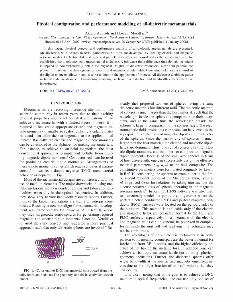
Metamaterials are receiving increasing attention in thescientific community in recent years due to their excitingphysical properties and novel potential applications.1–5 Toachieve a metamaterial with a desired figure of merit, it isrequired to first create appropriate electric and magnetic di-pole moments �in small-size scales� utilizing available mate-rials and then tailor their arrangement to the application ofinterest. Basically, the electric and magnetic dipole momentscan be envisioned as the alphabet for making metamaterials.For instance, to achieve an artificial magnetism, the mostconventional approach is to implement metallic loops offer-ing magnetic dipole moments.6 Conductor rods can be usedfor producing electric dipole moments.7 Arrangements ofthese dipole moments can establish required material param-eters, for instance, a double negative �DNG� metamaterialbehavior as depicted in Fig. 1.
Most of the metamaterial designs are constructed with theuse of metallic elements. The major drawbacks in using me-tallic inclusions are their conduction loss and fabrication dif-ficulties, especially in the optical frequencies. In addition,they show very narrow bandwidth resonant modes. Further,most of the known realizations are highly anisotropic com-posites. Recently, a new paradigm for metamaterial develop-ment was introduced by Holloway et al. in Ref. 8, wherethey used magnetodielectric spheres for generating requiredmagnetic and electric dipole moments. Later on, Vendik etal. used the same concept and suggested a more practicalapproach, such that only dielectric spheres are involved.9 Ba-
sically, they proposed two sets of spheres having the samedielectric materials but different radii. The dielectric materialof spheres is much larger than the host material, such that thewavelength inside the spheres is comparable to their diam-eters, and at the same time the wavelength outside thespheres is large in comparison to the spheres sizes. The elec-tromagnetic fields inside this composite can be viewed as thesuperposition of electric and magnetic dipoles and multipolesof the spheres. Since the permittivity of spheres is muchlarger than the host material, the electric and magnetic dipolefields are dominant. Thus, one set of spheres can offer elec-tric dipole moments, and the other set can provide magneticdipole moments. Because of the small-size spheres in termsof host wavelength, one can successfully assign the effectivematerial parameters ��ef f ,�ef f� to the bulk composite. Theconstitutive parameters were formulated originally by Lewinin Ref. 10 considering the spheres resonate either in the firstor second resonant modes of the Mie series. Then, Jylha etal. improved those formulations by taking into account theelectric polarizabilities of spheres operating in the magneticresonant modes.11 In Ref. 11, HFSS software was also usedto numerically model the periodic configuration where theperfect electric conductor �PEC� and perfect magnetic con-ductor �PMC� surfaces were located on the periodic sides ofthe structure. This method is applicable only if the electricand magnetic fields are polarized normal to the PEC andPMC surfaces, respectively. In a metamaterial, the electricand magnetic fields can, in general, be polarized in complexforms inside the unit cell and applying this technique maynot be appropriate.
The advantages of only-dielectric metamaterial in com-parison to its metallic counterpart are the better potential forfabrication from RF to optics, and the higher efficiency be-cause of not having the metallic loss. In addition, one canachieve an isotropic metamaterial design utilizing sphericalgeometry inclusions. Further, the dielectric spheres offerwider bandwidth at the electric and magnetic eigenfrequen-cies due to the larger fraction of unit-cell volume that theycan occupy.
It is worth noting that if the goal is to achieve a DNGmedium at optical frequencies, one can use only one set of
(a) (b)
Leff(ω)
Ceff(ω)
FIG. 1. �Color online� DNG metamaterial constructed from me-tallic loops and rods. �a� The geometry, and �b� its equivalent circuitmodel.
PHYSICAL REVIEW B 77, 045104 �2008�
1098-0121/2008/77�4�/045104�11� ©2008 The American Physical Society045104-1

spheres �magnetic resonant mode�, and embed them inside anegative permittivity plasmonic host material, such as metalsor semiconductors. This idea was first proposed by Seo et al.in Ref. 12. The obtained structure shows more robust char-acteristics over the double-spheres lattice design in terms offabrication tolerance and bandwidth, although the loss of thehost plasmonic medium �the metal� can be an issue.
The goal of the present work is to provide a comprehen-sive investigation of dielectric metamaterials. The physicalinsights and engineering concerns are addressed. We startwith the periodic photonic band-gap �PBG� crystals, anddemonstrate how the band-gap region is obtained as the re-sult of periodicity along the propagation direction and dif-fraction phenomena between the unit cells. The near-fieldpatterns before and after the gap region are plotted to betterunderstand the PBG behavior. Then, we modify the geometryof the PBG crystal by considering finite size disks instead ofthe infinite rods. The performance is analyzed, and transmis-sion coefficient and near-field patterns are determined. It isillustrated that the dielectric disks can interestingly createelectric and magnetic dipole moments at their resonantmodes, which can be successfully used for the metamaterialdevelopment. This process is basically nothing to do with theperiodicity and unit-cell diffractions along the direction ofpropagation, and allows one to accomplish a metamaterialwith very small-size ingredients. The concept is extended tospherical particles, and effective constitutive parameters�±� , ±�� are presented. A DNG all-dielectric metamaterial isdesigned. The dielectric metamaterial is free of conductionloss and provides a relatively high efficiency. The periodic�or possible random� arrangement of particles also sup-presses the radiation loss that each of the resonators producesindividually. It is shown that by embedding the dielectricparticles close to each other, the couplings between them areincreased, and the bandwidth of a negative permittivity-negative permeability region is effectively enhanced. Thecomplex metamaterial structures designed in this paper aremodeled using an advanced and versatile in-house developedfinite difference time domain �FDTD� technique.13,14
II. PERIODIC PHOTONIC CRYSTALS
Photonic crystals are a novel class of periodic dielectricstructures that by offering engineered dispersion diagrams
effectively manipulate the propagation of EM or opticalwaves.15,16 The discovery of PBG crystals created uniqueopportunities for proposing novel devices in both microwaveand terahertz frequencies.17–19 The main benefit of PBG ma-terials is their construction from all dielectric elements,which increases their feasibility for fabrication from RF tooptics. Although in the beginning the focus was on the utili-zation of the stop-band region of PBG for controlling thewaves, recently, other applications such as directive emis-sion, negative refraction, superlensing, etc., with the use ofother parts of the PBG dispersion diagram have beenhighlighted.20,21 One fact that must be carefully considered isthat the novel behaviors of the PBG are derived from theunit-cell interactions and periodic dielectric contrasts alongthe propagation direction, and one needs a specific unit-cellsize to achieve the required diffractions for accomplishingthe performance of interest. The problem is now twofold:first, the unit cell cannot be as small as one is interested in,and second, the diffraction phenomenon degrades the perfor-mance of the PBG in some specific applications such as di-rective emission or superlensing devices.
To show the effects of the unit-cell size and structure pe-riodicity on the PBG performance, a periodic configurationof dielectric rods with a diameter of d=1 cm, permittivity of�r=10.2, and a lattice constant of a=1.5 cm is depicted inFig. 2�a�. The rods are infinite along the z direction, andperiodic along the y direction. Five layers are considered inthe x direction. The FDTD is applied to obtain the transmis-sion coefficient for a plane wave with Ez−Hy polarization,propagating through the PBG structure �along the x direc-
(a) (b)
0
0.2
0.4
0.6
0.8
1
1.2
Ez
x-y plane
0
0.2
0.4
0.6
0.8
1
1.2
Ez
x-y plane
FIG. 3. �Color online� Near-field patterns forEz in the x-y plane �one unit cell� for five-layerrods; �a� before band gap �f1=2.80 GHz�, and �b�after band gap �f2=6.60 GHz�. Note the confine-ment of dielectric and air modes inside the dielec-tric and air regions, respectively.
(a) (b)
2.0 3.0 4.0 5.0 6.0 7.0Frequency (GHz)
−40
−35
−30
−25
−20
−15
−10
−5
0
Mag
nitu
deof
Tra
nsm
issi
onC
oeff
icie
nt(d
B)
5−layer Structure1−layer Structure
xy
z
εr=10.2a=1.5 cm
r=0.5 cm
Λ=1.5cm
FIG. 2. �Color online� Periodic structure of dielectric rods. �a�The geometry, and �b� its transmission coefficient. Note that onelayer of dielectric rods does not generate any band-gap region.
AKRAM AHMADI AND HOSSEIN MOSALLAEI PHYSICAL REVIEW B 77, 045104 �2008�
045104-2

tion�. The result is plotted in Fig. 2�b�. The periodicity ofstructure along the x direction opens up a stop-band regionbetween the dielectric and air modes for 0.19�a /�0�0.29�−10 dB transmission level� for the electromagnetic �EM�wave. The size of the unit cell dominantly determines thefrequency range of stop-band performance. The characteris-tic of the one-layer PBG �along the x� is also shown in Fig.2�b�. Because of the lack of periodicity and unit-cell diffrac-tions, no band-gap region in the frequency of interest is ob-served.
The Ez near-field patterns of five-layer PBG before andafter the band-gap region �at f1=2.80 GHz and f2=6.60 GHz� are shown in Fig. 3. It is observed that at fre-quencies before the band gap the electric field is concen-trated inside the dielectric region, giving it a lower fre-quency, while the mode just above the gap has most of itspower in the air region, so its frequency is raised a bit. Thissatisfies the electromagnetic variational theory applied to un-derstand the PBG concept.16 For the one-layer PBG near-field behaviors at f1 and f2 are obtained in Fig. 4, and onecannot observe the similar phenomena as what was obtainedfor the five-layer case.
Therefore, to achieve a desired performance utilizing thePBG concept �periodic dielectric contrast�, having periodic-ity and a relatively large size unit cell are essential. Onemight be able to reduce the size of the unit cell by increasingthe permittivity of the dielectric rod; however, this will in-
crease the interactions between the unit cells causing morediffractions along the propagation direction, which might notbe suitable for some applications. In the following sections,we will address how an engineered dispersion diagram maybe successfully tailored using a different concept that isbased on the creation of dipole modes inside the dielectricresonators. This will introduce a unique paradigm for thedevelopment of functional metamaterials.
III. DIELECTRIC DISKS: ELECTRIC AND MAGNETICDIPOLE CREATION
In this section, we introduce the concept of electric andmagnetic dipole moments, and address their potential appli-cations for metamaterial realization. To begin, let us considerthe five-layer PBG structure depicted in the previous sectionand modify the geometry by considering finite size diskswith thickness L=0.5 cm. The geometry is shown in Fig.5�a�. The FDTD is applied to characterize the structure andobtain the transmission coefficient. The result is plotted inFig. 5�b�. No band-gap region is observed. Now, we increasethe permittivity of dielectric disks to �r=60 such that a stop-band performance in the frequency range of 4.75� f�GHz��5.10 can be determined. Interesting enough, that even onelayer of this design can also provide the band-gap phenom-enon around the same center frequency �f =4.94 GHz�, hav-ing of course a narrower bandwidth, as shown in Fig. 5�c�.
(a) (b)
0
0.2
0.4
0.6
0.8
1
1.2
Ez
x-y plane
0
0.2
0.4
0.6
0.8
1
1.2
Ez
x-y plane
FIG. 4. �Color online� Near-field patterns forEz in the x-y plane �one unit cell� for one-layerrods at �a� f1=2.80 GHz, and �b� f2=6.60 GHz.
(a) (b) (c)
4.5 5.0 5.5 6.0 6.5Frequency (GHz)
−40
−35
−30
−25
−20
−15
−10
−5
0
Mag
nitu
deof
Tra
nsm
issi
onC
oeff
icie
nt(d
B)
εr=60
0.5 cm
Λy
Λz
Λx
4.5 5.0 5.5 6.0 6.5Frequency (GHz)
−40
−35
−30
−25
−20
−15
−10
−5
0
5
Mag
nitu
deof
Tra
nsm
issi
onC
oeff
icie
nt(d
B)
εr=10.2εr=60
FIG. 5. �Color online� Array of all-dielectric disks. �a� The geometry ��x=�y =�z=1.5 cm�, and transmission coefficients for �b�five-layer structure, and �c� one-layer structure.
PHYSICAL CONFIGURATION AND PERFORMANCE… PHYSICAL REVIEW B 77, 045104 �2008�
045104-3

To provide a physical understanding of this phenomenon,the electric and magnetic field patterns inside one unit cell ofthe one-layer disks array at f1=4.94 GHz are plotted in Fig.6 �snapshot in time�. One can observe that the near-fieldpatterns of the dielectric disk are very similar to those of amagnetic dipole oriented along the y direction. The near-fieldpatterns at the second and third resonant frequencies f2=5.97 GHz and f3=6.08 GHz are also plotted in Figs. 7 and8, respectively. The disk at the second resonant frequency isalmost equivalent to an electric dipole located along the zaxis. The third mode has a resonant frequency very close tothe second mode, and its magnetic field pattern in the equa-torial plane exhibits an octupole characteristic, consisting oftwo linear quadrupoles rotated by 90° with respect to eachother. Higher order resonant modes can also be generated bythe dielectric disks utilizing the mutipole modes.
Because of the very large permittivity material of the di-electric disk, one can consider the structure as a resonatorwhere most of the fields are localized inside the medium.Kejfez et al. have performed a comprehensive study of di-electric resonators in Ref. 22, and clearly illustrated the po-tential of dielectric cylindrical resonators for providing elec-tric and magnetic dipole moments. Semouchkina et al. havealso noticed the differences between the field patterns of in-finite rods PBG and finite-size cylinders.23 Peng et al. have
also recently illustrated the electric and magnetic mode de-velopment inside the very high permittivity rods.24 Consid-ering the polarization of the plane wave excitation, the threeresonant frequencies obtained in Fig. 5�c� can be attributedto HEM11�, TM01�, and HEM21� resonant modes,respectively.22 The near-field patterns for an isolated finite-size cylinder for the above resonant modes have been plottedin Ref. 22, and they closely resemble what has been demon-strated here for the periodic array of the disks. Hence, thestop-band regions in Fig. 5�c� are derived from the resonantmodes of the isolated disks, and thus even one layer of thestructure can provide the band-gap property of interest.
The HEM11� mode is sometimes called unconfined mode,because in the limit, as �r→�, its magnetic field does notvanished on the surfaces of the cavity resonator. This can berevealed from Fig. 6, where the magnetic field is normal tothe magnetic wall boundary of the cavity and cannot be zeroin the limiting case. In contrast, the TM01� mode is of theconfined type, since its magnetic field is tangent to theboundary of the cavity, and in the limit, as �r→�, it must bezero along the surface �see Fig. 7�. The mode confinementbehavior can also be readily seen by looking at the transmis-sion coefficient plot in Fig. 5�c�, where the HEM11� mode�magnetic dipole� presents a lower Q than the TM01� mode�electric dipole�. The octupole performance of the HEM21�
mode represents an inefficient radiator and consequently, itsQ factor is very large. It is worth noting that although each ofthe disk resonators individually has some radiation loss,when we arrange them in the periodic fashion, the couplingsbetween them are increased and the radiation loss is consid-erably suppressed.
Tailoring the dielectric disks allows one to successfullycontrol the physical performance of the design. For example,as mentioned earlier, the resonant frequency of the HEM21�
mode is very close to the electric dipole mode �TM01��, andif the TM01� mode is the desired mode of operation, theHEM21� mode may create an undesirable nearby resonanceeffect, and one might be interested in suppressing it. This canbe simply accomplished by placing a thin wire loop on theend face of the disk resonator where the electric field has astrong � component, or, for instance, since the TM01� modehas a relatively strong electric field along the axis of rotation,it is possible to tune this mode by removing the cylindrical
(a) (b)
E-Field
x-z plane
H-Field
y-x plane
FIG. 6. �Color online� Field distributions inside one unit cell ofthe one-layer disks array at f1=4.94 GHz �HEM11� mode�. �a� E inthe x-z plane, and �b� H in the y-x plane. Near fields are similar tothose of a magnetic dipole oriented along the y direction.
(a) (b)
E-Field
y-z plane
H-Field
y-x plane
FIG. 7. �Color online� Field distributions inside one unit cell ofthe one-layer disks array at f1=5.97 GHz �TM01� mode�. �a� E inthe y-z plane, and �b� H in the y-x plane. Near fields are similar tothose of an electric dipole oriented along the z direction.
(a) (b)
E-Field
y-x plane
H-Field
y-x plane
FIG. 8. �Color online� Field distributions inside one unit cell ofthe one-layer disks array at f3=6.08 GHz �HEM21� octupole mode�.�a� E and �b� H in the y-x plane.
AKRAM AHMADI AND HOSSEIN MOSALLAEI PHYSICAL REVIEW B 77, 045104 �2008�
045104-4

center section �leaving a doughnut shape� and replacing it bya movable dielectric rod.
In summary, the important conclusion of this section isthe fact that dielectric resonators can successfully provideelectric and magnetic dipole modes. The dipole moments canbe considered as the alphabet for making metamaterials. Forinstance, using an array structure of the magnetic dipoledisks �one layer� one can effectively provide a band-gap me-dium. The major advantage compared to the PBG concept isthat the unit-cell interaction along the propagation directionsis not required for achieving the functionality of interest.Basically, each of the disks itself provides the required reso-nant behavior. In general, by tailoring the electric and mag-netic dipole moments in one unit cell one can make abuilding-block cell with the figure of merit of interest. Then,by making a material from these small-size cells, one canclaim a metamaterial design with the homogeneous effectiveconstitutive parameters ��ef f ,�ef f�. This will be described inmore detail in the next section.
IV. METAMATERIAL REALIZATION
The materials presented in the previous section are veryhelpful in providing a physical understanding of the dipolemodes generation utilizing dielectric resonators. In this sec-tion, we apply this concept to design spherical particle-basedmetamaterials. Figure 9�a� shows a periodic array of dielec-tric spheres having high permittivity �p embedded inside thenonmagnetic host matrix �h. The structure has an isotropicunit cell. Using Mie theory, one can express the EM wavesof each sphere as an infinite series of spherical vector func-tions Mn and Nn. Applying the field transformation betweenthe nonconcentric spheres, and using the boundary condi-tions, the array of spheres can be solved analytically.10,25 It isassumed that the size of the spheres is comparable to theirmaterial wavelength, and small in terms of host materialwavelength, so that the effective material parameters can beaccurately defined for the structure. As demonstrated earlier,the dielectric resonators can offer electric and magnetic di-pole moments, and higher order modes. Indeed, from theMie series, it clears that the dominant modes �n=1� are TE�magnetic dipole� and TM �electric dipole� waves. Around
the eigenfrequencies of these modes one can assume the ex-istence of only the electric and magnetic modes and obtainthe effective material parameters ��ef f ,�ef f� for the periodicspheres as8
�ef f = �h�1 +3 f
�pF�� + 2�h
�pF�� − �h− f� , �1a�
�ef f = �0�1 +3 f
F�� + 2
F�� − 1− f� , �1b�
where f is volume fraction of the spheres, and function F��is
F�� =2�sin − cos �
�2 − 1�sin + cos , �2�
with
4.0 4.5 5.0 5.5 6.0 6.5 7.0 7.5Frequency (GHz)
−40
−35
−30
−25
−20
−15
−10
−5
0
Mag
nitu
deof
Tra
nsm
issi
onC
oeff
icie
nt(d
B)
FIG. 10. Transmission coefficient for the all-dielectric spheresdepicted in Fig. 9�a�. The first and second resonances representmagnetic and electric resonant modes, respectively.
(a) (b)
4 4.5 5 5.5 6 6.5 7−10
−8
−6
−4
−2
0
2
4
6
8
10
Frequency (GHz)
Eff
ecti
veC
on
stit
uti
veP
aram
eter
s
εeff,r
µeff,r
εr=40
Λy
Λz
FIG. 9. �Color online� Array ofone-layer all-dielectric spheres.�a� The geometry ��y =�z
=2.5 cm�, and �b� its effectiveconstitutive parameters.
PHYSICAL CONFIGURATION AND PERFORMANCE… PHYSICAL REVIEW B 77, 045104 �2008�
045104-5

= k0r��p,r, �3�
where r is the radius of spheres. It is interesting to emphasizethat the nonmagnetic spheres can create magnetism due tothe magnetic dipole polarization.
The effective constitutive parameters of the periodicspheres depicted in Fig. 9�a�, having dielectric constant �p,r=40, radius r=0.5 cm, and unit-cell size �x=1.5 cm, �y=�z=2.5 cm, are plotted in Fig. 9�b�. The first resonant fre-quency at fm=4.72 GHz is associated with the magneticmode and the second resonance at fe=6.61 GHz representsthe electric mode. As described earlier, the magnetic mode isan unconfined mode and provides a wider bandwidth. Thiscan be seen from Fig. 9�b� and Eq. �1�, where one can find alarger bandwidth for the TE resonance in comparison to theTM resonance by a factor of about �p /�h. It is worth notingthat above the resonant frequencies of magnetic and electricmodes, negative permeability and negative permittivity ma-terials are established, respectively. This will be used later inthis section for the metamaterial realization of DNG behav-ior.
The FDTD is applied to characterize the structure andobtain the transmission coefficient for a plane wave propa-gating through the medium �one layer along x�. The resultis shown in Fig. 10. Comparing Fig. 9�b� with Fig. 10, one
can observe that the analytical formulations �1� closely esti-mate the first two resonant frequencies determined throughthe FDTD full wave analysis �less than 1% error�. However,as expected, the third resonant frequency at f =6.73 GHzcannot be predicted based on Eq. �1�. In practice, the thirdresonant frequency can set an upper limit on the frequencyband of the second mode where the effective permittivity isdefined. It is interesting to note that the transmission coeffi-cient behavior of the dielectric spheres is very similar tothat of the dielectric disks �see Fig. 5�c��. The near-field dis-tributions are plotted in Fig. 11 for the first two resonantfrequencies �fm=4.73 GHz and fe=6.55 GHz� and clearlyvalidate the existence of magnetic and electric dipole polar-izations.
Thus far, we have described how one can successfullyrealize a metamaterial with both electric and magnetic pa-rameters utilizing only-dielectric resonators, fulfilling de-sired effective constitutive parameters. The next step is toinvestigate the possibility of increasing the bandwidth of theresonant modes. But, first let us clear one issue. Consider, forinstance, the magnetic resonant mode of the one-layer peri-odic spheres �Fig. 9�a��, having −10 dB bandwidth of aboutBW=1.2%. It is well understood that each of the cavity reso-nators can be considered as a parallel LC circuit. Cascadingthe LC resonant circuits can increase the transmission coef-ficient bandwidth. In fact, increasing the number of layers
(a) (b)
4.0 4.5 5.0 5.5 6.0 6.5 7.0 7.5Frequency (GHz)
−40
−35
−30
−25
−20
−15
−10
−5
0
Mag
nitu
deof
Tra
nsm
issi
onC
oeff
icie
nt(d
B)
Λx
FIG. 12. �Color online� Arrayof three-layer dielectric spheres��x=1.5 cm�. �a� The geometry,and �b� its transmissioncoefficient.
(a) (b)
x-z plane
E-Field
y-x plane
H-Field
y-z plane
E-Field
y-x plane
H-Field
FIG. 11. �Color online� Field distributions inside one unit cell of the spheres array. �a� E in the x-z plane and H in the y-x plane atfm=4.73 GHz, representing the magnetic dipole moment, and �b� E in the y-z plane and H in the y-x plane at fe=6.55 GHz, representing theelectric dipole moment. �1.5 cm�1.5 cm of the unit cell in the y-z directions is plotted�.
AKRAM AHMADI AND HOSSEIN MOSALLAEI PHYSICAL REVIEW B 77, 045104 �2008�
045104-6

�parallel LC circuits� increases the transmission coefficientbandwidth. However, it should be noticed that this is nothingto do with the bandwidth of the metamaterial. The perfor-mance of three layers of the spheres designed in Fig. 9�a� isshown in Fig. 12. The transmission bandwidth is increasedfrom 1.2% to about 4.6%; but, both one-layer and three-layerstructures have almost the same �ef f given by Eq. �1b�, andof course the similar permeability bandwidth. Increasing thenumber of layers will simply increase the thickness of thestructure.
In this work, a very unique approach for the bandwidthenhancement of metamaterials is presented. Recently, Mos-allaei et al. demonstrated how the bandwidth of the negativepermeability medium realized utilizing metallic embedded-loop circuits can be improved by increasing the couplingsbetween the loop elements.26 In fact, based on their circuitmodel analogy it is shown that the bandwidth of the negativepermeability medium depends strongly on the coupling co-efficient � between the loops, and can be estimated from thefollowing equation:
�
�p=
1�1 − �2
− 1, �4�
where �p is the resonant frequency of the loops, and ��1.The higher the coupling coefficient � the larger the band-width. This concept is applied here to the all-dielectricmetamaterial design. Basically, we increase the couplings be-tween the spheres shown in Fig. 9�a�, by bringing themcloser to each other along the z direction, namely, assuming�z=1.5 cm �Fig. 13�a��. Transmission coefficient for themagnetic mode is plotted in Fig. 13�b� illustrating a band-width enhancement of more than 100% compared to theoriginal design ��z=2.5 cm�. An almost similar observationfor the electric mode resonance is illustrated in Fig. 13�c��bandwidth is increased from 0.5% to 1.3%�. Basically, whenwe make the spheres closer to each other, the mode radiationthrough the spheres is increased causing the reduction inthe Q factor of each of the spheres, resulting in the band-width enhancement of the resonant modes. Slight shifts in
(a) (b) (c)
6.3 6.4 6.5 6.6 6.7Frequency (GHz)
−40
−35
−30
−25
−20
−15
−10
−5
0
Mag
nitu
deof
Tra
nsm
issi
onC
oeff
icie
nt(d
B)
Λz=1.5 cmΛz=2.5 cm
Λy
Λz
4.6 4.7 4.8 4.9 5.0Frequency (GHz)
−40
−35
−30
−25
−20
−15
−10
−5
0
Mag
nitu
deof
Tra
nsm
issi
onC
oeff
icie
nt(d
B)
Λz=1.5 cmΛz=2.5 cm
FIG. 13. �Color online� Bandwidth enhancement of metamaterial by increasing couplings between the elements �smaller unit-cell size�,�a� the geometry, �b� transmission coefficient at the magnetic resonance, and �c� transmission coefficient at the electric resonance. The morethe couplings the wider the bandwidth.
(a) (b)
6.1 6.2 6.3 6.4 6.5 6.6 6.7 6.8 6.9Frequency (GHz)
−40
−35
−30
−25
−20
−15
−10
−5
0
Mag
nitu
deof
Tra
nsm
issi
onC
oeff
icie
nt(d
B)
εr=23.8εr=40Double−sphere Struc.Loss Tangent=.001
εr=40
εr=23.8
Λy
Λz
Lh
Ch
C1
L1
L2C2
FIG. 14. �Color online� DNG metamaterial constructed from all-dielectric spheres, �a� the geometry ��y =2.5 cm,�z=1.5 cm�, and itsequivalent circuit model, and �b� transmission coefficient.
PHYSICAL CONFIGURATION AND PERFORMANCE… PHYSICAL REVIEW B 77, 045104 �2008�
045104-7

the resonant frequencies due to the coupling effects are alsonoted.
We will now investigate the development of double nega-tive metamaterials using dielectric resonators. As highlightedearlier, and can be seen from Fig. 9�b�, the periodic array ofdielectric spheres can generate both negative effective per-meability and permittivity, however, at different resonant fre-quencies �fm=4.72 GHz, fe=6.61 GHz�. To obtain a DNGbehavior around the same resonant frequency, a building-block unit cell constructed from two spheres having the samesize but different dielectric constants �p1,r=40 and �p2,r=23.8, is optimized in Fig. 14�a�. The set of spheres with�p1,r=40 creates negative effective permittivity about fe=6.50 GHz, and the set of spheres with �p2,r=23.8 generatesnegative effective permeability about fm=6.29 GHz. Figure14�b� presents transmission coefficients of both sets, wherestop-band regions are determined in the negative materialfrequency ranges. It must be mentioned that in the con-structed lattice of both spheres �Fig. 14�a��, the electric modehas a higher Q compared to the magnetic mode, and hence,the coupling effect of the sphere with dielectric �p2,r=23.8on the electric resonance should be larger than that of thesphere with dielectric �p1,r=40 on the magnetic resonance.This phenomenon is carefully explained from another pointof view in Ref. 11; as is discussed the electric polarizabilityof the dielectric sphere operating in the magnetic resonancehas an influence on the electric mode sphere, causing theelectric resonance of the double-sphere lattice to be slightlylower than that of the single-sphere lattice �less than 1%shift�. The magnetic resonance stays almost the same �non-magnetic spheres�. Thus, in Fig. 14�b�, the electric resonanceof the single-sphere lattice should be slightly shifted down toenvision the negative permittivity region of the double-sphere lattice. Considering this, a region with both negative �and � is accomplished. Transmission coefficient for thedouble-sphere unit cell is shown in Fig. 14�b�, demonstratingan almost total transmission in the DNG region, around f=6.42 GHz. The phase of the field distribution at f=6.42 GHz inside one layer of the metamaterial is shown inFig. 15. The positive slope for the phase in the central regionof the layer clears the establishment of the DNG medium
�backward wave�. The electric and magnetic field intensitiesinside the unit cell at this frequency are also shown in Fig.16. One can clearly observe the development of electric andmagnetic dipole modes that provide the required effectivematerial parameters. This also validates the existence of thedipolar modes assumption, made in the derivation of Eq. �1�.The effect of the loss is also studied, by considering sphereswith a dielectric loss tangent of tan �=0.001. The result isplotted in Fig. 14�b�, illustrating less than −1 dB transmis-sion loss in the DNG region. Utilizing dielectric materialswith better loss tangents can of course provide a higher effi-ciency.
The same concept can be used to design a DNG metama-terial realized utilizing dielectric disks, which might beeasier for fabrication in some cases. The geometry is de-picted in Fig. 17�a�. Transmission coefficients and field pat-terns at f =5.97 GHz are evaluated in Figs. 17�b� and 18.Similar observations as the spherical particles are accom-plished.
(a) (b) (c)
εr=23.8
E-Field
x-z plane
E-Field
y-z plane
εr=40 εr=23.8H-Field
y-x plane
εr=40 εr=23.8
FIG. 16. �Color online� Field distributions inside one unit cell of the DNG metamaterial �Fig. 14�a�� at f =6.42 GHz. �a� E in the y-zplane, �b� H in the y-x plane, and �c� E in the x-z plane. Note the creation of electric and magnetic dipole moments inside the unit cell ofthe spheres of �r=40 and �r=23.8.
0 2 4 6 8 10-90
-85
-80
-75
-70
-65
-60
-55
-50
-45
-40-40
Distance (mm)
Ph
ase
(deg
ree)
FIG. 15. Phase distribution of the electric field Ez inside thelayer of DNG metamaterial �Fig. 14�a�� at f =6.42 GHz. The planewave propagates from left to the right where the phase is increasedin this direction. The positive slope for the phase in the central partof the layer is a demonstration of the backward wave generation.
AKRAM AHMADI AND HOSSEIN MOSALLAEI PHYSICAL REVIEW B 77, 045104 �2008�
045104-8

V. OPTICAL METAMATERIALS
Realization of metamaterials at terahertz frequencies isalso of great interest due to the possibility of designing novelnanoscale devices in the infrared and visible regimes.27–32
The concept of all-dielectric metamaterials can be extendedto the optical frequencies; however, because of the fabrica-tion limitations one needs to use smaller value dielectric ma-terials for the resonating inclusions. In this case, larger-sizeresonators may be implemented. Figure 19�a� depicts an ar-ray of gallium phosphide �GaP� spheres with permittivity12.25 and a dielectric loss tangent of tan �=0.001. The di-ameter of spheres is 170 nm. Transmission coefficient per-formance is shown in Fig. 19�b�, where the development ofmagnetic and electric resonant modes can be observed. Onemust notice that because of the low dielectric material of thespheres and their relatively large physical size the couplingsbetween the resonators are increased. This will generatesome difficulty in tuning the DNG medium if two sets ofspheres are used. Although the existing coupling may not be
desirable from the fact that the electric and magnetic reso-nances are coupled, it can be beneficial from the point thatone can successfully tailor a backward wave using the stronginteraction between the spheres. Work is currently underprogress in this direction.
Alternative approaches will be to embed one set of dielec-tric spheres inside a plasmonic host medium as obtained bySeo et al.;12 or to use Drude material coated spheres as pro-posed by Wheeler.32 Here, we investigate the former methodby characterizing the performance of the periodic array ofGaP spheres implanted inside cesium �Cs� host material witha measured plasma wavelength �p=0.41 �m and a dampingconstant � of 51�1012,12 shown in Fig. 20�a�. Note that ifone operates close to the plasma frequency, the index of hostmaterial is small, and physically large-size spheres are stillelectrically small in comparison to the host wavelength.Transmission coefficient of the composite structure is shownin Fig. 20�b�. The spheres operate at their magnetic resonantmode and can provide negative effective permeability �seeFig. 19�b��. A combination of this with the negative permit-
(a) (b)
5.8 5.9 6.0 6.1 6.2Frequency (GHz)
−40
−35
−30
−25
−20
−15
−10
−5
0
Mag
nitu
deof
Tra
nsm
issi
onC
oeff
icie
nt(d
B)
εr=43εr=60Double−disc Struc.Loss Tangent=.001
Λy
Λz
εr=60
εr=43
FIG. 17. �Color online� DNG metamaterial constructed from all-dielectric disks, �a� the geometry ��y =2.5 cm,�z=1.5 cm�, and �b� itstransmission coefficient.
(a) (b)E-Field
y-z plane
εr=60 εr=43
H-Field
y-x plane
εr=60 εr=43
FIG. 18. �Color online� Field distributions inside one unit cell of the DNG metamaterial �Fig. 17�a�� at f =5.97 GHz. �a� E in the y-zplane, and �b� H in the y-x plane. Note the creation of electric and magnetic dipole moments inside the unit cell of the disks of �r=60 and�r=43.
PHYSICAL CONFIGURATION AND PERFORMANCE… PHYSICAL REVIEW B 77, 045104 �2008�
045104-9

tivity of cesium below its plasma resonance offers DNG be-havior. In comparison to the double-sphere resonators de-sign, here only one set of resonators is involved and a widerbandwidth can be expected. In addition, the spheres operatein their magnetic mode frequency range, which inherentlyoffers a lower Q than the electric mode. Transmission lossfor this case is about −1.1 dB. The magnetic field pattern atf =529 THz is shown in Fig. 20�c�.
VI. SUMMARY
In this paper, a comprehensive investigation of all-dielectric metamaterials is addressed. The FDTD full waveanalysis is applied to characterize the interactions of EM-optical waves with the periodic array of metamaterials, andtailor required designs. Electric and magnetic near-field pat-terns are established to highlight the physical insights.
Photonic crystals are searched first, and it is describedthat the band-gap phenomenon appears as a result of the
periodic dielectric contrasts along the propagation direction.Then, the concept of electric and magnetic dipole modesgeneration for metamaterial development is presented. Di-electric disk and spherical particle resonators are imple-mented to create required dipole moments. Arrangements ofelectric and magnetic dipole moments in one unit cell tailorthe metamaterial to the application of interest. The beautyof the developed metamaterial is that even one unit cell ofthe structure can provide the figure of merit of interest,and the interactions between the cells is not essential, as wasthe case for the PBG. This will allow for making the small-size unit cell, and defining the effective constitutive param-eters accurately. Further, a random arrangement might havethe potential of offering the similar desired properties, espe-cially in the spherical resonator case where the unit cell isisotropic.
The physics of electric and magnetic dipole moments areexplored. It is shown that the magnetic resonance is an un-confined mode and has a lower Q than the confined electric
(a) (b)
450.0 500.0 550.0 600.0 650.0 700.0 750.0 800.0Frequency (THz)
−40
−35
−30
−25
−20
−15
−10
−5
0
Mag
nitu
deof
Tra
nsm
issi
onC
oeff
icie
nt(d
B)
Λy
Λz
GaP
FIG. 19. �Color online� Metamaterial nanostructured spheres. �a� The geometry ��y =�z=250 nm�, and �b� its transmission coefficient.Note the generation of magnetic and electric resonances.
(a) (b) (c)
475.0 500.0 525.0 550.0 575.0 600.0Frequency (THz)
−30
−25
−20
−15
−10
−5
0
Mag
nitu
deof
Tra
nsm
issi
onC
oeff
icie
nt(d
B)
Plasmonic HostDNG Material
y-z plane
H-Field
GaP
Cs
FIG. 20. �Color online� DNG optical metamaterial constructed from nanostructured dielectric spheres �operating in magnetic mode�embedded in negative permittivity host. �a� The geometry, �b� transmission coefficient, and �c� H field in the y-z plane at f =529 THz.
AKRAM AHMADI AND HOSSEIN MOSALLAEI PHYSICAL REVIEW B 77, 045104 �2008�
045104-10

resonant mode. A unique approach is proposed to increasethe bandwidth of the resonant particles. Basically, by bring-ing the dielectric resonators closer to each other, the radia-tion couplings between them are increased, resulting in low-ering the Q of each of the resonators. This will establishbandwidth enhancement. Dielectric metamaterials are free ofconduction loss and can provide high efficiency perfor-mance.
A DNG metamaterial constructed from two sets ofspheres, having the same size but different materials, is de-veloped. One set of spheres provides negative permittivity,and the other set offers negative permeability, accomplishingthe double negative metamaterial. One can also design adouble-sphere lattice DNG metamaterial using the spheres of
different sizes but having the same materials. Developmentof negative index media at terahertz frequencies using plas-monic materials is also studied.
In general, all-dielectric metamaterials appear very prom-ising for addressing some of the important physical and en-gineering concerns, such as the loss and bandwidth. They arequite feasible for fabrication in both microwave and IR-visible spectrums.
ACKNOWLEDGMENT
This work is supported in part by the U.S. Air Force Of-fice of Scientific Research �AFOSR� Grant No. FA9550-07-1-0133.
*[email protected] J. B. Pendry, Phys. Rev. Lett. 85, 3966 �2000�.2 R. A. Shelby, D. R. Smith, and S. Schultz, Science 292, 77
�2001�.3 N. Engheta and R. W. Ziolkowski, Metamaterials: Physics and
Engineering Explorations �John Wiley & Sons, Inc., New York,2006�.
4 C. Caloz and T. Itoh, Electromagnetic Metamaterials: Transmis-sion Line Theory and Microwave Applications �John Wiley &Sons, Inc., New York, 2006�.
5 G. V. Eleftheriades and K. G. Balmain, Negative-RefractionMetamaterials �John Wiley & Sons, Inc., New York, 2005�.
6 J. B. Pendry, A. J. Holden, D. J. Robbins, and W. J. Stewart,IEEE Trans. Microwave Theory Tech. 47, 2075 �1999�.
7 J. B. Pendry, A. J. Holden, D. J. Robbins, and W. J. Stewart, J.Phys.: Condens. Matter 10, 4785 �1998�.
8 C. L. Holloway, E. F. Kuester, J. Baker-Jarvis, and P. Kabos,IEEE Trans. Antennas Propag. 51, 2596 �2003�.
9 O. G. Vendik, and M. S. Gashinova, in Proceedings of the 34thEuropean Microwave Conference, Amsterdam, Netherlands,2004, pp. 1209–1212.
10 L. Lewin, Proc. Inst. Electr. Eng. 94, 65 �1947�.11 L. Jylha, I. Kolmakov, S. Maslovski, and S. Tretyakov, J. Appl.
Phys. 99, 043102 �2006�.12 B. J. Seo, T. Ueda, T. Itoh, and H. Fetterman, Appl. Phys. Lett.
88, 161122 �2006�.13 H. Mosallaei and Y. Rahmat-Samii, Electromag. J. 23, 135
�2003�.14 A. Taflove and S. C. Hagness, Computational Electrodynamics:
The Finite-Difference Time-Domain Method, 3rd ed. �ArtechHouse, MA, 2005�.
15 E. Yablonovitch, Phys. Rev. Lett. 58, 2059 �1987�.16 J. D. Joannopoulos, R. D. Meade, and J. N. Winn, Photonic Crys-
tals �Princeton University Press, Princeton, NJ, 1995�.17 IEEE Trans. Microwave Theory Tech. 47 �1999�.18 E. Burstein and C. Weisbuchin, in Confined Electrons and Pho-
tons: New Physics and Applications, Proceedings of NATO Ad-
vanced Study Institute of Confined Electrons and Photons: NewPhysics and Applications, Italy, July 13–26, 1993; ConfinedElectrons and Photons: New Physics and Applications see alsoin Series B: Physics �Plenum, New York, 1995�, Vol. 340.
19 Photonic Band Gap Materials, edited by C. M. Soukoulis, Pro-ceedings of NATO Advanced Study Institute Photonic Band GapMaterials, Elounda, Crete, Greece, June 18–30, 1995; PhotonicBand Gap Materials, edited by C. M. Soukoulis see also SeriesE Applied Sciences �Kluwer Academic, Dordrecht, Germany,1966�, Vol. 315.
20 S. Enoch, G. Tayeb, and B. Gralak, IEEE Trans. AntennasPropag. 51, 2659 �2003�.
21 P. V. Parimi, W. T. Lu, P. Vodo, and S. Sridhar, Nature �London�426, 404 �2003�.
22 D. Kajfez and P. Guilllon, Dielectric Resonators �Artech House,Inc., Dedham, MA, 1986�.
23 E. A. Semouchkina, G. B. Semouchkin, M. Lanagan, and C. A.Randall, IEEE Trans. Microwave Theory Tech. 53, 1477 �2005�.
24 L. Peng, L. Ran, H. Chen, H. Zhang, J. A. Kong, and T. M.Grzegorczyk, Phys. Rev. Lett. 98, 157403 �2007�.
25 P. C. Waterman and N. E. Pedersen, J. Appl. Phys. 59, 2609�1986�.
26 H. Mosallaei and K. Sarabandi, IEEE Trans. Antennas Propag.55, 45 �2007�.
27 N. Engheta, A. Salandrino, and A. Alù, Phys. Rev. Lett. 95,095504 �2005�.
28 A. Alu and N. Engheta, J. Opt. Soc. Am. B 23, 571 �2006�.29 A. K. Iyer and G. V. Eleftheriades, J. Opt. Soc. Am. B 23, 553
�2006�.30 V. M. Shalaev, W. Cai, U. K. Chettiar, H. K. Yuan, A. K. Sary-
chev, V. P. Drachev, and A. V. Kildishev, Opt. Lett. 30, 3356�2005�.
31 D. Korobkin, Y. Urzhumov, and G. Shvets, J. Opt. Soc. Am. B23, 468 �2006�.
32 M. S. Wheeler, J. S. Aitchison, and M. Mojahedi, Phys. Rev. B73, 045105 �2006�.
PHYSICAL CONFIGURATION AND PERFORMANCE… PHYSICAL REVIEW B 77, 045104 �2008�
045104-11


![Dielectric Metamaterials with Toroidal Dipolar Responsesoukoulis.physics.iastate.edu/publications/425.pdfthe metamaterial concept [29]. This concept enables us to access to novel and](https://static.fdocuments.us/doc/165x107/5f38760a10d28b7c576aca21/dielectric-metamaterials-with-toroidal-dipolar-the-metamaterial-concept-29-this.jpg)


