Physica B: Condensed Matter
7
Contents lists available at ScienceDirect Physica B: Condensed Matter journal homepage: www.elsevier.com/locate/physb Microstructure and thermodynamic investigation of NieTi system produced by mechanical alloying A. Rostami a , G.A. Bagheri b,∗ , S.K. Sadrnezhaad b a School of Electrical and Computer Engineering, University of Tehran, P.O. Box: 1439957131, Tehran, Iran b Department of Materials Science and Engineering, Sharif University of Technology, Azadi Ave., P.O. Box: 11155-9466, Tehran, Iran ARTICLE INFO Keywords: Amorphous materials Miedema's semi empirical method NiTi intermetallic compound Mechanical alloying ABSTRACT In this study, an equiatomic mixture of Ni and Ti powders has been mechanically milled for 180 h in a planetary mill in order to study the product phase of milling process. Miedema's semi empirical method has been used in order to calculate the energy of solid solution and amorphous phases and the effect of defects like dislocations and grain boundaries have been considered in this thermodynamic approach. The results showed that amor- phous phase is more stable than solid solution after mechanical milling process. It seems these results are in contrast with Mousavi et al. [1] results but there are some points that we should consider in this approach. Applying of common tangent rule and considering the grain boundaries and dislocation energies in this ther- modynamic approach lead to anticipating of amorphous phase as the stable phase after mechanical alloying process while lack of considering these terms in Mousavi et al. study led to different results. The milled powders has been heat treated at 950ᵒC for 20 min and finally, XRD and SEM analysis have been performed in order to evaluate experimental phases and compare experimental and theoretical results. Crystallite size and lattice strain have been calculated using Williamson-Hall equation and XRD patterns. 1. Introduction NiTi intermetallic compound (nitinol) has been found as a proper material for applications in medical and engineering areas due to its particular properties like shape memory effect, super elasticity, bio- compatibility, vibration dumping and good erosion resistance [1–4]. The shape memory effect of this material is due to the transformation between high temperature austenite phase (B2) and low temperature martensite phase (B19′). Different procedures such as casting, powder metallurgy, self-propagating high temperature synthesis and mechan- ical alloying have been used in order to produce NiTi [5]. Conventional methods like melting and casting are energy consuming and hard to control the segregation of elements during solidification. Mechanical alloying is a solid state technique for producing super saturated solid solutions, amorphous materials, metal based nanocomposites and oxide dispersion-strengthened materials in temperatures far below melting temperatures of constituents. In this technique, repeated collisions of balls together leads to energy transferring to the trapped particles be- tween two balls and plastic deformation of powder particles [6]. The density of lattice defects like dislocations and grain boundaries in- creases during milling process, and solid solution or amorphous phase will produce depend on Gibbs free energy of system. Miedema manner is a semi empirical method for calculating the Gibbs free energy of solid solution and amorphous phase of binary or ternary solid systems considering three chemical, structural and elastic terms of enthalpy [7–10]. But original Miedema thermodynamic pro- cedure is not suitable for prediction of mechanical milling product phases because of high amounts of defects especially dislocations and grain boundaries in the lattice of milled samples. Needless to say these defects increase the Gibbs free energy of system while original Miedema manner does not count these energies in the calculation of Gibbs free energy. So, we calculated Gibbs free energy of NieTi system using Miedema approach and then the terms of dislocations and grain boundaries energies have been considered in final Gibbs free energy of system. Finally, the results of thermodynamic approach have been compared with experimental results. 2. Experimental procedure An equiatomic mixture of Ni (99.9% purity and particle size less than 106μ) and Ti (99% purity and particle size less than 20μ) powders was charged into a planetary mill and milling process was performed for 180 h under argon atmosphere in order to prevent undesired reac- tions of powders. The milling speed and ball to powder weight ratio https://doi.org/10.1016/j.physb.2018.10.015 Received 12 September 2018; Received in revised form 2 October 2018; Accepted 8 October 2018 ∗ Corresponding author. E-mail addresses: [email protected] (A. Rostami), [email protected] (G.A. Bagheri), [email protected] (S.K. Sadrnezhaad). Physica B: Condensed Matter 552 (2019) 214–220 Available online 10 October 2018 0921-4526/ © 2018 Elsevier B.V. All rights reserved. T
Transcript of Physica B: Condensed Matter
Contents lists available at ScienceDirect
Physica B: Condensed Matter
journal homepage: www.elsevier.com/locate/physb
Microstructure and thermodynamic investigation of NieTi system producedby mechanical alloying
A. Rostamia, G.A. Bagherib,∗, S.K. Sadrnezhaadb
a School of Electrical and Computer Engineering, University of Tehran, P.O. Box: 1439957131, Tehran, IranbDepartment of Materials Science and Engineering, Sharif University of Technology, Azadi Ave., P.O. Box: 11155-9466, Tehran, Iran
A R T I C L E I N F O
Keywords:Amorphous materialsMiedema's semi empirical methodNiTi intermetallic compoundMechanical alloying
A B S T R A C T
In this study, an equiatomic mixture of Ni and Ti powders has been mechanically milled for 180 h in a planetarymill in order to study the product phase of milling process. Miedema's semi empirical method has been used inorder to calculate the energy of solid solution and amorphous phases and the effect of defects like dislocationsand grain boundaries have been considered in this thermodynamic approach. The results showed that amor-phous phase is more stable than solid solution after mechanical milling process. It seems these results are incontrast with Mousavi et al. [1] results but there are some points that we should consider in this approach.Applying of common tangent rule and considering the grain boundaries and dislocation energies in this ther-modynamic approach lead to anticipating of amorphous phase as the stable phase after mechanical alloyingprocess while lack of considering these terms in Mousavi et al. study led to different results. The milled powdershas been heat treated at 950ᵒC for 20min and finally, XRD and SEM analysis have been performed in order toevaluate experimental phases and compare experimental and theoretical results. Crystallite size and lattice strainhave been calculated using Williamson-Hall equation and XRD patterns.
1. Introduction
NiTi intermetallic compound (nitinol) has been found as a propermaterial for applications in medical and engineering areas due to itsparticular properties like shape memory effect, super elasticity, bio-compatibility, vibration dumping and good erosion resistance [1–4].The shape memory effect of this material is due to the transformationbetween high temperature austenite phase (B2) and low temperaturemartensite phase (B19′). Different procedures such as casting, powdermetallurgy, self-propagating high temperature synthesis and mechan-ical alloying have been used in order to produce NiTi [5]. Conventionalmethods like melting and casting are energy consuming and hard tocontrol the segregation of elements during solidification. Mechanicalalloying is a solid state technique for producing super saturated solidsolutions, amorphous materials, metal based nanocomposites and oxidedispersion-strengthened materials in temperatures far below meltingtemperatures of constituents. In this technique, repeated collisions ofballs together leads to energy transferring to the trapped particles be-tween two balls and plastic deformation of powder particles [6]. Thedensity of lattice defects like dislocations and grain boundaries in-creases during milling process, and solid solution or amorphous phasewill produce depend on Gibbs free energy of system.
Miedema manner is a semi empirical method for calculating theGibbs free energy of solid solution and amorphous phase of binary orternary solid systems considering three chemical, structural and elasticterms of enthalpy [7–10]. But original Miedema thermodynamic pro-cedure is not suitable for prediction of mechanical milling productphases because of high amounts of defects especially dislocations andgrain boundaries in the lattice of milled samples. Needless to say thesedefects increase the Gibbs free energy of system while original Miedemamanner does not count these energies in the calculation of Gibbs freeenergy. So, we calculated Gibbs free energy of NieTi system usingMiedema approach and then the terms of dislocations and grainboundaries energies have been considered in final Gibbs free energy ofsystem. Finally, the results of thermodynamic approach have beencompared with experimental results.
2. Experimental procedure
An equiatomic mixture of Ni (99.9% purity and particle size lessthan 106μ) and Ti (99% purity and particle size less than 20μ) powderswas charged into a planetary mill and milling process was performedfor 180 h under argon atmosphere in order to prevent undesired reac-tions of powders. The milling speed and ball to powder weight ratio
https://doi.org/10.1016/j.physb.2018.10.015Received 12 September 2018; Received in revised form 2 October 2018; Accepted 8 October 2018
∗ Corresponding author.E-mail addresses: [email protected] (A. Rostami), [email protected] (G.A. Bagheri), [email protected] (S.K. Sadrnezhaad).
Physica B: Condensed Matter 552 (2019) 214–220
Available online 10 October 20180921-4526/ © 2018 Elsevier B.V. All rights reserved.
T
have been chosen 180 RPM and 10:1 respectively. 1 wt.% Stearic acidwas used as process control agent (PCA) in order to inhibit agglom-eration of powders and sticking of powders to the wall of the containerand balls. The heat treatment of milled powders has been done at 950ᵒCfor 20min under argon atmosphere.
X-ray diffraction (XRD) analysis of milled powders and heat treatedpowders were performed by X-ray Diffractometer (EQuniox 3000, Inel,France) with CuKα (λ=1.54 Å) radiation. Scanning electron micro-scope (SEM, LEO 1400) with energy dispersive X-ray spectrometer(EDS) and FESEM were used to study the morphology and compositionof the powders after different milling times.
3. Results and discussion
3.1. Thermodynamic analysis
The Gibbs free energy formation of A-B solution can be calculatedby equation (1) [11]:
= −ΔG ΔH TΔSsms s (1)
Where ΔHms and ΔSs are enthalpy and entropy of mixing respec-
tively. T is the temperature of solid solution formation. It is noticeablethat the constituent energies are in the standard state. ΔSs has beenconsidered equal to the entropy of mixing of ideal solution, then it canbe calculated by equation (2) as follows [11]:
= − +ΔS R(x ·lnx x ·lnx )sA A B B (2)
(R) and (x) are universal gas constant and molar fraction of con-stituents respectively.
According to Miedema's semi-empirical method, solid solution en-thalpy of formation consists of three contribution terms [7–10]:
= + +ΔH ΔH ΔH ΔHschemical elastic structural (3)
ΔHchemical is the chemical contribution of enthalpy which is the same forboth solid and liquid solutions. ΔHelastic term is related to size mismatchbetween two or more constituents and finally ΔHstructural contribution isrelated to crystal structures of solvent and solute and the difference inthe number of valence electrons [12,13]. The amount of ΔHchemical in abinary system can be determined by the following equation [7–10]:
=+
+
× − + −− −
ΔH2Pf(C )(x V x V )
(n ) (n )[ (ΔΦ ) Q
P(Δn ) S
P]chemical
SA A
2/3B B
2/3
wsA 1/3
wsB 1/3
* 2ws1/3 2
(4)
where Φ*, nws and (V) are work function, electron density and molarvolume respectively, (P) and (Q) are empirical constants and xA and xBare mole fractions of constituents. f(C )S or concentration function canbe achieved by equations (5) and (6) for solid solutions [7–10]:
=f(C ) C CSAS
BS (5)
=
+
=
+
Cx V
x V x V, and C
x Vx V x VA
S A A2/3
A A2/3
B B2/3 B
S B B2/3
A A2/3
B B2/3 (6)
The elastic term of enthalpy can be calculated by equation (7) [3,7]:
= +ΔH x x (x ΔE x ΔE )elastic A B A A in B B B in A (7)
ΔEA in B is the induced elastic energy due to dissolving of A atoms in Band conversely about ΔEB in A. These amounts can be determined byequation (8) [3,7]:
=
+
=
+
ΔE 2K ·G (ΔV)3K ·V 4G V
, ΔE 2K ·G (ΔV)3K ·V 4G VA in B
A B2
A B B AB in A
B A2
B A A B (8)
(K) and (G) are bulk and shear modulus respectively.The structural term of enthalpy is related to binary alloys of both
transition metals like NieTi which have partly filled d-shells. If weassume that solid solution atoms form a common d-bond, we can esti-mate the structural enthalpy of solid solution using the empirical curve
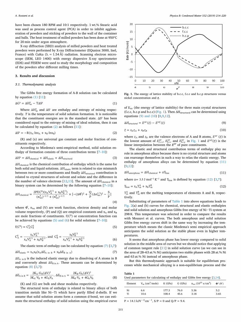
of Estr (the energy of lattice stability) for three main crystal structures(f.c.c, h.c.p and b.c.c) (Fig. 1). Then ΔHstructural can be determined usingequations (9) and (10) [8,9,12].
= −H E z E zΔ (¯) ( ¯)structuralstr ref (9)
= +z x z x z¯ A A B B (10)
where zA and zB are the valence electrons of A and B atoms, Estr (z̄) isthe lowest amount of Ef c c
str. . , Eb c c
str. . and Eh c p
str. . in Fig. 1 and Eref (z̄) is the
linear interpolation between the Estr of pure constituents.The elastic and structural contribution terms of enthalpy play no
role in amorphous alloys because there is no crystal structure and atomscan rearrange themselves in such a way to relax the elastic energy. Theenthalpy of amorphous alloys can be determined by equation (11)[9,12]:
= +ΔH ΔH αTamorphous chemical fuse (11)
where =− −α 3.5 J mol K1 1 and Tfuse is defined by equation (12) [3,7]:
= +T x T x Tfuse A mA
B mB (12)
TmA and Tm
B are the melting temperatures of elements A and B, respec-tively.
Substituting of parameters of Table 1 into above equations leads toFig. 2(a) and (b) curves for chemical, structural and elastic enthalpiesand solid solution and amorphous Gibbs free energy of NieTi system at298 K. This temperature was selected in order to compare the resultswith Mousavi et al. curves. The both amorphous and solid solutionGibbs free energy curves shift in the same way by increasing the tem-perature which means the classic Miedema's semi empirical approachanticipates the solid solution as the stable phase even in higher tem-peratures.
It seems that amorphous phase has lower energy compared to solidsolution in the middle area of curves but we should notice that applyingof common tangent rule [11] in solid solution curve (as we can see inthe area of 28–63 at.% Ni) anticipates two stable phases with 28 at.% Niand 63 at.% Ni instead of amorphous phase.
But this thermodynamic approach is suitable for equilibrium pro-cesses while mechanical alloying is a non-equilibrium process and the
-15
-10
-5
0
5
10
15
20
0 10 20 30 40 50 60 70 80 90 100
Estr
(KJ/
mol
e)
xNi
b.c.cf.c.ch.c.p
Fig. 1. The energy of lattice stability of b.c.c, f.c.c and h.c.p structures versusnickel concentration and z̄.
Table 1Used parameters for calculating of enthalpy and Gibbs free energy [3,14].
Element Vm (cm3/mole) K (GPa) G (GPa) nws (1023 e/cm3) ∗ VΦ ( )
Ni 6.6 177.3 76.0 5.36 5.2Ti 10.6 108.4 45.6 3.18 3.65
P= 14.1 kJV−2 cm−1, S/P= 0 and Q/P=9.4.
A. Rostami et al. Physica B: Condensed Matter 552 (2019) 214–220
215
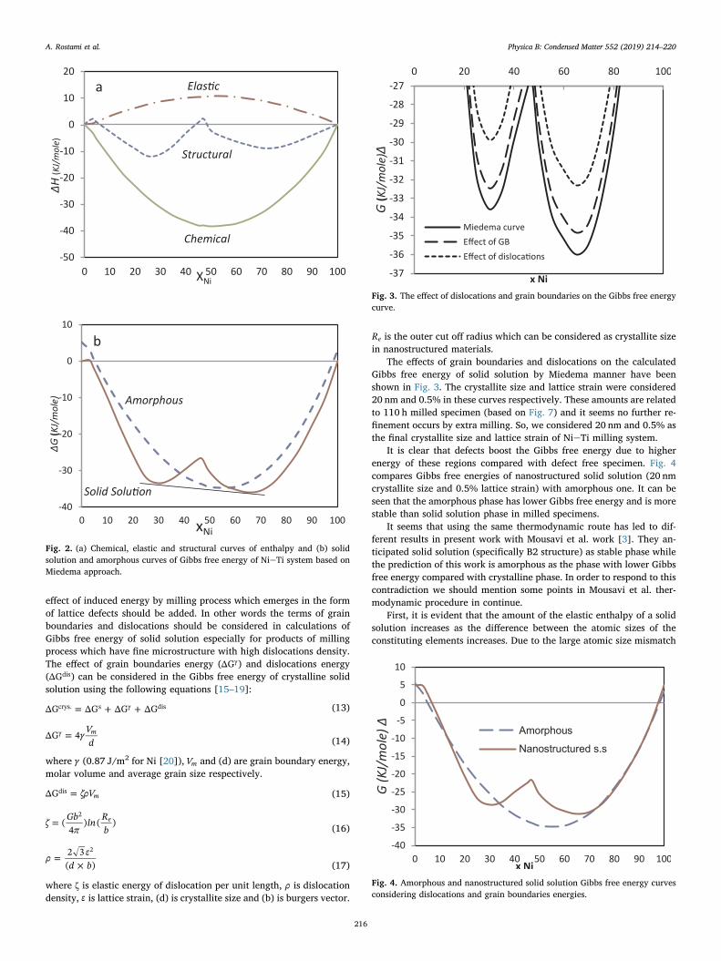
effect of induced energy by milling process which emerges in the formof lattice defects should be added. In other words the terms of grainboundaries and dislocations should be considered in calculations ofGibbs free energy of solid solution especially for products of millingprocess which have fine microstructure with high dislocations density.The effect of grain boundaries energy (ΔGγ) and dislocations energy(ΔGdis) can be considered in the Gibbs free energy of crystalline solidsolution using the following equations [15–19]:
= + +ΔG ΔG ΔG ΔGcrys. s γ dis (13)
= γ Vd
ΔG 4 mγ(14)
where γ (0.87 J/m2 for Ni [20]), Vm and (d) are grain boundary energy,molar volume and average grain size respectively.
= ζρVΔG mdis (15)
=ζ Gbπ
ln Rb
(4
) ( )e2
(16)
=
×
ρ εd b2 3( )
2
(17)
where ζ is elastic energy of dislocation per unit length, ρ is dislocationdensity, ε is lattice strain, (d) is crystallite size and (b) is burgers vector.
Re is the outer cut off radius which can be considered as crystallite sizein nanostructured materials.
The effects of grain boundaries and dislocations on the calculatedGibbs free energy of solid solution by Miedema manner have beenshown in Fig. 3. The crystallite size and lattice strain were considered20 nm and 0.5% in these curves respectively. These amounts are relatedto 110 h milled specimen (based on Fig. 7) and it seems no further re-finement occurs by extra milling. So, we considered 20 nm and 0.5% asthe final crystallite size and lattice strain of NieTi milling system.
It is clear that defects boost the Gibbs free energy due to higherenergy of these regions compared with defect free specimen. Fig. 4compares Gibbs free energies of nanostructured solid solution (20 nmcrystallite size and 0.5% lattice strain) with amorphous one. It can beseen that the amorphous phase has lower Gibbs free energy and is morestable than solid solution phase in milled specimens.
It seems that using the same thermodynamic route has led to dif-ferent results in present work with Mousavi et al. work [3]. They an-ticipated solid solution (specifically B2 structure) as stable phase whilethe prediction of this work is amorphous as the phase with lower Gibbsfree energy compared with crystalline phase. In order to respond to thiscontradiction we should mention some points in Mousavi et al. ther-modynamic procedure in continue.
First, it is evident that the amount of the elastic enthalpy of a solidsolution increases as the difference between the atomic sizes of theconstituting elements increases. Due to the large atomic size mismatch
-50
-40
-30
-20
-10
0
10
20
0 10 20 30 40 50 60 70 80 90 100
H(K
J/m
ole)
XNi
Chemical
Structural
Elas ca
-40
-30
-20
-10
0
10
0 10 20 30 40 50 60 70 80 90 100
G(K
J/m
ole)
xNi
Amorphous
Solid Solu on
b
Fig. 2. (a) Chemical, elastic and structural curves of enthalpy and (b) solidsolution and amorphous curves of Gibbs free energy of NieTi system based onMiedema approach.
-37
-36
-35
-34
-33
-32
-31
-30
-29
-28
-270 20 40 60 80 100
G(K
J/m
ole)
x Ni
Miedema curveEffect of GBEffect of disloca ons
Fig. 3. The effect of dislocations and grain boundaries on the Gibbs free energycurve.
-40
-35
-30
-25
-20
-15
-10
-5
0
5
10
0 10 20 30 40 50 60 70 80 90 100
G(K
J/m
ole)
x Ni
Amorphous
Nanostructured s.s
Fig. 4. Amorphous and nanostructured solid solution Gibbs free energy curvesconsidering dislocations and grain boundaries energies.
A. Rostami et al. Physica B: Condensed Matter 552 (2019) 214–220
216
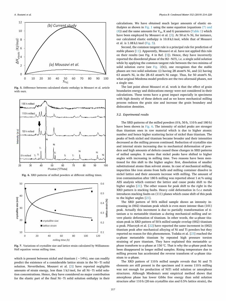
which is present between nickel and titanium (∼14%), one can readilypredict the existence of a considerable lattice strain in the NieTi solidsolution. Nevertheless, Mousavi et al. [3] have reported negligibleamounts of strain energy, less than 1 kJ/mol, for all NieTi solid solu-tion concentrations. Hence, they have considered no major contributionfor the elastic part of the final NieTi solid solution enthalpy in their
calculations. We have obtained much larger amounts of elastic en-thalpies as shown in Fig. 1 using the same equation (equations (7) and(8)) and the same amounts for Vm, K and G parameters (Table 1) whichhave been employed by Mousavi et al. [3]. At 50 at.% Ni, for instance,our calculated elastic enthalpy is 10.8 kJ/mol, while that of Mousaviet al. is 1.08 kJ/mol (Fig. 5).
Second, the common tangent rule is a principal rule for prediction ofstable phases [11]. Apparently, Mousavi et al. have not applied this ruleon their results (see Fig. 4 in Ref. [3]). Hence, they have incorrectlyreported the disordered phase of the B2eNiTi, i.e. a single solid solutionwhile by applying the common tangent rule between the two minima ofsolid solution curve (see Fig. 2(b)), one recognizes that the stablephases are two solid solutions: (i) having 28 atom% Ni, and (ii) having63 atom% Ni, in the 28–63 atom% Ni range. Thus, for 50 atom% Ni,what original Miedema model predicts are the two aforesaid phases, nota single one.
The last point about Mousavi et al. work is that the effect of grainboundaries energy and dislocations energy were not considered in theircalculations. These terms have a great impact especially in specimenswith high density of these defects and as we know mechanical millingprocess reduces the grain size and increase the grain boundary anddislocation densities.
3.2. Experimental results
The XRD patterns of the milled powders (0 h, 50 h, 110 h and 180 h)have been shown in Fig. 6. The intensity of nickel peaks are strongerthan titanium ones in raw material which is due to higher atomicnumber and hence higher scattering factor of nickel than titanium. Thepeaks of both nickel and titanium became broader and their intensitiesdecreased as the milling process continued. Reduction of crystallite sizeand internal strain increasing due to mechanical deformation of pow-ders and high amounts of defects caused these changes in XRD patternsof milled samples. It seems that nickel peaks have shifted to higherangles with increasing in milling time. Two reasons have been men-tioned for this shift to the higher angles: first, dissolution of smallersubstitutional atoms than solvent atoms. In case of mechanical milling,impurities like iron atoms from balls and milling container dissolve innickel lattice and their amounts increase with milling. The amount ofiron contamination after 180 h milling was reported about 1 at.% usingAES analysis which contract the lattice and cause peaks shift to thehigher angles [21]. The other reason for peak shift to the right in theXRD pattern is stacking faults. Heavy cold deformation in f.c.c metalsintroduces stacking faults on (111) planes which cause shift of this peakto the higher angles [21].
The XRD pattern of 50 h milled sample shows an intensity in-creasing in (002) titanium peak which is even more intense than (101)peak. Actually this increment is due to partially transformation of ti-tanium α to metastable titanium ω during mechanical milling and se-vere plastic deformation of titanium. In other words, the ω-phase tita-nium peak in XRD pattern of 50 h milled sample overlap (002) titaniumα peak. Pilarczyk et al. [22] have reported the same increment in (002)titanium peak after mechanical alloying of Ni and Ti powders but theyreported no reason for this phenomenon. Todaka et al. [23] reached theω-phase metastable titanium by repeated high pressure torsionstraining of pure titanium. They have explained this metastable ω-phase transform to α-phase at 150 °C. That is why the ω-phase peak hasbeen disappeared in longer milled samples. Rising temperature due tomilling process has accelerated the reverse transform of ω-phase tita-nium to α-phase.
The XRD pattern of 110 h milled sample reveals that Ni and Tielements are still present in the specimen and it seems 110 h millingwas not enough for production of NiTi solid solution or amorphousstructures. Although Miedema's semi empirical method shows thatamorphous phase has lower Gibbs free energy than solid solutionstructure after 110 h (20 nm crystallite size and 0.5% lattice strain), the
0
2
4
6
8
10
12
0 10 20 30 40 50 60 70 80 90 100
H ela
sc(K
J/m
ol)
xNi
(a) Mousavi et al.
(b) Current study
Fig. 5. Difference between calculated elastic enthalpy in Mousavi et al. articlewith ours.
Fig. 6. XRD patterns of milled powders at different milling times.
0.1
0.2
0.3
0.4
0.5
0.6
10
20
30
40
50
0 20 40 60 80 100 120
la st
rain
(%)
rst
allit
si (n
m)
milling me (h)
crystallite size
la ce strain
Fig. 7. Variations of crystallite size and lattice strain calculated by Williamson-Hall equation versus milling time.
A. Rostami et al. Physica B: Condensed Matter 552 (2019) 214–220
217
XRD pattern introduces only Ti and Ni elements after 110 h milling. Itmeans the energy of milling process after 110 h was not enough toconquer the activation energy of NiTi solid solution or amorphousformation.
After 180 h milling, all peaks of Ni and Ti elements disappeared anda halo pattern formed which indicates formation of an amorphousphase, as the other researchers have reported [6,24–26]. It is clear thatfurther milling up to 180 h, would not lead to formation of solid solu-tion because the lattice defects increase with mechanical milling pro-cess [21]. These results confirm thermodynamic calculations whichintroduced the amorphous phase as the product stable phase of milledNi and Ti powders.
Fig. 7 shows the variations of crystallite size and lattice strain ofnickel milled powders until 110 h using Williamson-Hall equation andXRD patterns of milled samples. It is clear that the crystallite size ofnickel dropped off considerably by increasing in milling time but ittends to a constant value which further refinement will not happen.This crystallite size refinement can be explained by studying of dis-locations in milled samples. There are three main reasons for activationof dislocation locking mechanism and hardness increasing in milledsamples: 1) Arriving of titanium atoms into the nickel lattice and for-mation of solid solution, 2) the dislocation density increment due tohard working effect of mechanical milling and 3) segregation of tita-nium atoms in the stacking faults of nickel. Equation (11) shows thelinear relation between hardness and minimum distance between two
adjacent dislocations in a pile up. In short, mechanical milling increasesdislocation density and hardness and decreases the minimum distancebetween two dislocations in a pile up and this small distances lead tothe formation of low angle grain boundaries and eventually smallercrystals [19,27–29].
= −L Gb π h3 / (1 ϑ)
where (L) is the minimum distance between two dislocations in a pileup, (G) is the shear modulus, (b) is the burgers vector, (ϑ) is the Poissonratio and (h) is the hardness.
The lattice strain of nickel increases during milling process. It is dueto increasing in lattice defects density and specifically dislocationdensity. Dissolution of titanium or iron atoms in nickel and distortion ofnickel lattice is another reason for lattice strain increasing in Fig. 7.
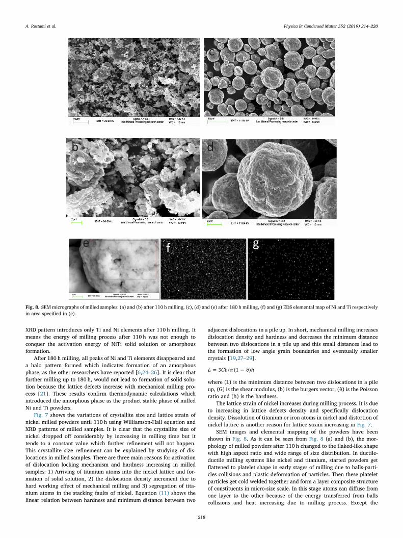
SEM images and elemental mapping of the powders have beenshown in Fig. 8. As it can be seen from Fig. 8 (a) and (b), the mor-phology of milled powders after 110 h changed to the flaked-like shapewith high aspect ratio and wide range of size distribution. In ductile-ductile milling systems like nickel and titanium, started powders getflattened to platelet shape in early stages of milling due to balls-parti-cles collisions and plastic deformation of particles. Then these plateletparticles get cold welded together and form a layer composite structureof constituents in micro-size scale. In this stage atoms can diffuse fromone layer to the other because of the energy transferred from ballscollisions and heat increasing due to milling process. Except the
Fig. 8. SEM micrographs of milled samples: (a) and (b) after 110 h milling, (c), (d) and (e) after 180 h milling, (f) and (g) EDS elemental map of Ni and Ti respectivelyin area specified in (e).
A. Rostami et al. Physica B: Condensed Matter 552 (2019) 214–220
218
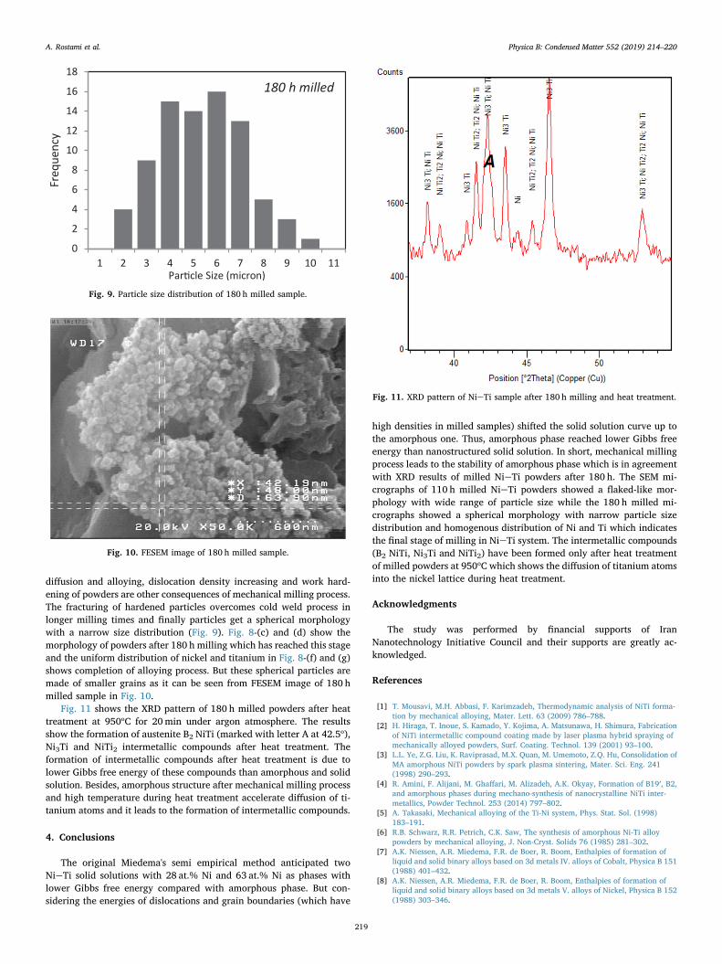
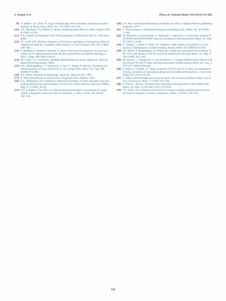
diffusion and alloying, dislocation density increasing and work hard-ening of powders are other consequences of mechanical milling process.The fracturing of hardened particles overcomes cold weld process inlonger milling times and finally particles get a spherical morphologywith a narrow size distribution (Fig. 9). Fig. 8-(c) and (d) show themorphology of powders after 180 h milling which has reached this stageand the uniform distribution of nickel and titanium in Fig. 8-(f) and (g)shows completion of alloying process. But these spherical particles aremade of smaller grains as it can be seen from FESEM image of 180 hmilled sample in Fig. 10.
Fig. 11 shows the XRD pattern of 180 h milled powders after heattreatment at 950ᵒC for 20min under argon atmosphere. The resultsshow the formation of austenite B2 NiTi (marked with letter A at 42.5ᵒ),Ni3Ti and NiTi2 intermetallic compounds after heat treatment. Theformation of intermetallic compounds after heat treatment is due tolower Gibbs free energy of these compounds than amorphous and solidsolution. Besides, amorphous structure after mechanical milling processand high temperature during heat treatment accelerate diffusion of ti-tanium atoms and it leads to the formation of intermetallic compounds.
4. Conclusions
The original Miedema's semi empirical method anticipated twoNieTi solid solutions with 28 at.% Ni and 63 at.% Ni as phases withlower Gibbs free energy compared with amorphous phase. But con-sidering the energies of dislocations and grain boundaries (which have
high densities in milled samples) shifted the solid solution curve up tothe amorphous one. Thus, amorphous phase reached lower Gibbs freeenergy than nanostructured solid solution. In short, mechanical millingprocess leads to the stability of amorphous phase which is in agreementwith XRD results of milled NieTi powders after 180 h. The SEM mi-crographs of 110 h milled NieTi powders showed a flaked-like mor-phology with wide range of particle size while the 180 h milled mi-crographs showed a spherical morphology with narrow particle sizedistribution and homogenous distribution of Ni and Ti which indicatesthe final stage of milling in NieTi system. The intermetallic compounds(B2 NiTi, Ni3Ti and NiTi2) have been formed only after heat treatmentof milled powders at 950ᵒC which shows the diffusion of titanium atomsinto the nickel lattice during heat treatment.
Acknowledgments
The study was performed by financial supports of IranNanotechnology Initiative Council and their supports are greatly ac-knowledged.
References
[1] T. Mousavi, M.H. Abbasi, F. Karimzadeh, Thermodynamic analysis of NiTi forma-tion by mechanical alloying, Mater. Lett. 63 (2009) 786–788.
[2] H. Hiraga, T. Inoue, S. Kamado, Y. Kojima, A. Matsunawa, H. Shimura, Fabricationof NiTi intermetallic compound coating made by laser plasma hybrid spraying ofmechanically alloyed powders, Surf. Coating. Technol. 139 (2001) 93–100.
[3] L.L. Ye, Z.G. Liu, K. Raviprasad, M.X. Quan, M. Umemoto, Z.Q. Hu, Consolidation ofMA amorphous NiTi powders by spark plasma sintering, Mater. Sci. Eng. 241(1998) 290–293.
[4] R. Amini, F. Alijani, M. Ghaffari, M. Alizadeh, A.K. Okyay, Formation of B19′, B2,and amorphous phases during mechano-synthesis of nanocrystalline NiTi inter-metallics, Powder Technol. 253 (2014) 797–802.
[5] A. Takasaki, Mechanical alloying of the Ti-Ni system, Phys. Stat. Sol. (1998)183–191.
[6] R.B. Schwarz, R.R. Petrich, C.K. Saw, The synthesis of amorphous Ni-Ti alloypowders by mechanical alloying, J. Non-Cryst. Solids 76 (1985) 281–302.
[7] A.K. Niessen, A.R. Miedema, F.R. de Boer, R. Boom, Enthalpies of formation ofliquid and solid binary alloys based on 3d metals IV. alloys of Cobalt, Physica B 151(1988) 401–432.
[8] A.K. Niessen, A.R. Miedema, F.R. de Boer, R. Boom, Enthalpies of formation ofliquid and solid binary alloys based on 3d metals V. alloys of Nickel, Physica B 152(1988) 303–346.
0
2
4
6
8
10
12
14
16
18
1 2 3 4 5 6 7 8 9 10 11
Freq
uency
Par cle Size (micron)
180 h milled
Fig. 9. Particle size distribution of 180 h milled sample.
Fig. 10. FESEM image of 180 h milled sample.
Fig. 11. XRD pattern of NieTi sample after 180 h milling and heat treatment.
A. Rostami et al. Physica B: Condensed Matter 552 (2019) 214–220
219
[9] H. Bakker, G.F. Zhou, H. Yang, Mechanically driven disorder and phase transfor-mations in alloys, Prog. Mater. Sci. 39 (1995) 159–241.
[10] A.R. Miedema, F.R. DeBoer, R. Boom, Predicting heat effects in alloys, Physica 103B (1981) 67–81.
[11] D.R. Gaskell, Introduction to the Thermodynamics of Materials, fifth ed., CRC press,2008.
[12] P.I. Loeff, A.W. Weeber, Diagrams of formation enthalpies of amorphous alloys incomparison with the crystalline solid solution, J. Less Common. Met. 140 (1988)299–305.
[13] S. Sheibani, S. Heshmati-Manesh, A. Ataie, Structural investigation on nano-crys-talline Cu–Cr supersaturated solid solution prepared by mechanical alloying, J.Alloy. Comp. 495 (2010) 59–62.
[14] W.F. Gale, T.C. Totemeier, Smithells Metals Reference Book, eighth ed., ElsevierButterworth-Heinemann, 2004.
[15] N.K. Mukhopadhyay, D. Mukherjee, S. Bera, I. Manna, R. Manna, Synthesis andcharacterization of nano-structured Cu–Zn ɣ-brass alloy, Mater. Sci. Eng. 485(2008) 673–680.
[16] G.E. Dieter, Mechanical Metallurgy, third ed., McGraw-Hill, 1976.[17] D. Hull, Introduction to Dislocations, Pergamon Press, Oxford, 1965.[18] G.K. Williamson, R.E. Smallman, Dislocation densities in some annealed and cold
worked metals from measurements on the X-ray Debby-Scherrer spectrum, Philos.Mag. A 1 (1956) 34–46.
[19] G.H.A. Bagheri, The effect of reinforcement percentages on properties of coppermatrix composites reinforced with TiC particles, J. Alloy. Comp. 676 (2016)120–126.
[20] L.E. Murr, Interfacial Phenomena in Metals and Alloys, Addison-Wesley publishingcompany, 1975.
[21] C. Suryanarayana, Mechanical alloying and milling, Prog. Mater. Sci. 46 (2001)1–184.
[22] W. Pilarczyk, R. Nowosielski, A. Pilarczyk, P. Sakiewicz, A production attempt ofNi50Ti50 and Ni52Ti41Nb7 alloys by mechanical alloying method, Mater. Sci. Eng.47 (2011) 19–26.
[23] Y. Todaka, J. Sasaki, T. Moto, M. Umemoto, Bulk submicrocrystalline ω-Ti pro-duced by high-pressure torsion straining, Scripta Mater. 59 (2008) 615–618.
[24] B.S. Murty, S. Ranganathan, M. Mohan Rao, Solid state amorphization in binary Ti-Ni, Ti-Cu and ternary Ti-Ni-Cu system by mechanical alloying, Mater. Sci. Eng. A149 (1992) 231–240.
[25] W. Maziarz, J. Dutkiewicz, J. Van Humbeeck, T. Czeppe, Mechanically alloyed andhot pressed Ni–49.7Ti alloy showing martensitic transformation, Mater. Sci. Eng. A375–377 (2004) 844–848.
[26] J. Eckert, L. Schultz, K. Urban, Synthesis of Ni-Ti and Fe-Ti alloys by mechanicalalloying: formation of amorphous phases and extended solid solutions, J. Non-Cryst.Solids 127 (1991) 90–96.
[27] J. Eckert, Relationships governing the grain size of nanocrystalline metals and al-loys, Nanostruct. Mater. 6 (1995) 413–416.
[28] J. Eckert, I. Borner, Nanostructure formation and properties of ball-milled NiAl,Mater. Sci. Eng. A 239–240 (1997) 619–624.
[29] C.C. Koch, The synthesis and structure of nanocrystalline materials produced bymechanical attrition: a review, Nanostruct. Mater. 2 (1993) 109–129.
A. Rostami et al. Physica B: Condensed Matter 552 (2019) 214–220
220


![Physica B- Condensed Matter Volume 407 Issue 21 2012 [Doi 10.1016%2Fj.physb.2012.06.041] Chen, Song; Cai, Kefeng; Zhao, Wenyu -- The Effect of Te Doping on the Electronic Structure](https://static.fdocuments.us/doc/165x107/55cf9488550346f57ba2aca7/physica-b-condensed-matter-volume-407-issue-21-2012-doi-1010162fjphysb201206041.jpg)